SpInside Macintosh 2.0.2
Table of Contents
Preface
_______________________________________________________________________________
PREFACE
_______________________________________________________________________________
About SpInside Macintosh
Inside Macintosh: The Book
The Languages
What’s in Each Volume
Version Numbers
Compatibility
A Horse of a Different Color
The Structure of a Typical Chapter
Conventions
_______________________________________________________________________________
»ABOUT SPINSIDE MACINTOSH
_______________________________________________________________________________
SpInside Macintosh is an attempt at putting the entire contents of “Inside Macintosh” into a useable electronic format. It has been inspired by developer feedback on the Technical Notes Stack, “Phil & Dave’s Excellent CD”, and by the need for an electronic version of our beloved “Inside Mac.” At this stage, SpInside Macintosh is nothing more than a rough development PROTOTYPE.
It combines “Inside Macintosh” Volumes I-V into a single, sometimes coherent, electronic source. This text has not been rewritten for this format (i.e., we even left the Lisa references), but we did try to correct small things where we could. Information from Volumes IV and V has been inserted where deemed appropriate into the original text; however, some paragraphs may seem out of place. We tried to note machine- or system software-dependent references where the text may not have been clear, and we also incorporated an interim chapter on the Script Manager 2.0 and completely replaced the Sound Manager chapter. Hopefully, we haven’t introduced any new errors to the original text.
The chapters are numbered according to their order in this stack, and other than navigation through this stack, these numbers have neither a correlation to the original chapter numbers nor any other significance.
We’re distributing SpInside Macintosh as a development prototype because we feel it is more important for you to have it to use right now than to wait for us to finish a release-quality version. We also really want your feedback on it, so you, the real users of “Inside Macintosh,” can have a hand in designing your ideal electronic version instead of us telling you how it should be. Tell us what you like and dislike about the format, organization, and usefulness (or lack thereof). It is this feedback, both good and bad, that will ultimately decide the future of SpInside Mac and its derivatives.
Thanks for your support and especially for your patience. Have at it!
_______________________________________________________________________________
»Inside Macintosh: The Book
Inside Macintosh is a five-volume set of manuals that tells you what you need to know to write software for the Macintosh family of computers. Although directed mainly toward programmers writing standard Macintosh applications, Inside Macintosh also contains the information needed to write simple utility programs, desk accessories, device drivers, or any other Macintosh software. It includes:
• the user interface guidelines for applications on the Macintosh
• a complete description of the routines available for your program
to call (both those built into the Macintosh and others on disk),
along with related concepts and background information
• a description of the Macintosh 128K, 512K, and Plus hardware
It does not include information about:
• Programming in general.
• Getting started as a developer. For this, write to:
Developer Programs
Apple Computer, Inc.
20525 Mariani Avenue, M/S 75-2C
Cupertino, CA 95014
(408) 974-4897
• Any specific development system, except where indicated. You’ll
need to have additional documentation for the development system
you’re using.
• The Standard Apple Numerics Environment (SANE), which your program
can access to perform extended-precision floating-point arithmetic
and transcendental functions. This environment is described in the
Apple Numerics Manual.
• A description of Macintosh family hardware since the Macintosh Plus.
Refer to the “Macintosh Family Hardware Reference” for this information.
• A description of card architecture and programming techniques for
slot-based Macintosh systems. Refer to “Designing Cards and Drivers
for the Macintosh II and Macintosh SE” for this information.
You should already be familiar with the basic information that’s in Macintosh, the owner’s guide, and have some experience using a standard Macintosh application (such as MacWrite).
_______________________________________________________________________________
»The Languages
The routines described in this book are written in assembly language, but (with a few exceptions) they’re also accessible from higher-level languages. The first four volumes of Inside Macintosh document the interfaces to these routines on the Lisa Workshop development system. A powerful new development system, the Macintosh Programmers Workshop (MPW), is now available. Volume V documents the MPW Pascal interfaces to the routines and the symbolic identifiers defined for assembly-language programmers using MPW. These identifiers are usually identical to their Lisa Workshop counterparts. If
you’re using a different development system, its documentation should tell you how to apply the information presented here to that system.
Inside Macintosh is intended to serve the needs of both high-level language and assembly-language programmers. Every routine is shown in its Pascal form (if it has one), but assembly-language programmers are told how they can access the routines. Information of interest only to assembly-language programmers is set apart and labeled so that other programmers can conveniently skip it.
Familiarity with MPW Pascal (or a similar high-level language) is recommended for all readers, since it’s used for most examples. MPW Pascal is described in the documentation for the Macintosh Programmer’s Workshop.
_______________________________________________________________________________
»What’s in Each Volume
Inside Macintosh consists of five volumes. Volume I begins with the following information of general interest:
• a “road map” to the software and the rest of the documentation
• the user interface guidelines
• an introduction to memory management (the least you need to know,
with a complete discussion following in Volume II)
• some general information for assembly-language programmers
It then describes the various parts of the User Interface Toolbox, the software in ROM that helps you implement the standard Macintosh user interface in your application. This is followed by descriptions of other, RAM-based software
that’s similar in function to the User Interface Toolbox. (The software overview in the Road Map chapter gives further details.)
Volume II describes the Operating System, the software in ROM that does basic tasks such as input and output, memory management, and interrupt handling. As in Volume I, some functionally similar RAM-based software is then described.
Volume III discusses your program’s interface with the Finder and then describes the Macintosh 128K and 512K hardware. A comprehensive summary of all the software is provided, followed by some useful appendices and a glossary of all terms defined in Inside Macintosh.
Volume IV is a companion to the first three volumes that gives specific information on writing software to take advantage of the features of the Macintosh Plus and the Macintosh 512 enhanced. A familiarity with the material presented in the first three volumes is assumed, since most of the information presented in Volume IV consists of changes and additions to that original material. This volume also introduces four additional chapters—“The System Resource File”, “The List Manager”, “The SCSI Manager”, and “The Time Manager”.
Volume V presents new material specific to the Macintosh SE and Macintosh II computers. Familiarity with the material presented in the first four volumes is assumed, since most of the information presented in Volume V consists of changes and additions to that original material.
_______________________________________________________________________________
»Version Numbers
This edition of SpInside Macintosh describes the following versions of the software:
• version 105 of the ROM in the Macintosh 128K or 512K
• version 112 of the ROM image installed by MacWorks in the Macintosh XL
• version 117 ($75) of the ROM in the Macintosh Plus and
Macintosh 512K enhanced
• version 118 ($76) of the ROM in the Macintosh SE
• version 120 ($78) of the ROM in the Macintosh II
• version 1.1 and 2.0 of the Lisa Pascal interfaces and
the assembly-language definitions
• version 2.0 of the MPW Pascal interfaces and
the assembly-language definitions
Some of the RAM-based software is read from the file named System (usually kept in the System Folder). This manual describes the software in the System file whose creation date is May 2, 1984, System file version 3.2 whose creation date is June 4, 1986, and System file version 4.1. In certain cases, a feature can be found in earlier versions of the System file; these cases are noted in the text.
_______________________________________________________________________________
»Compatibility
Version 117 ($75) of the ROM, also known as the 128K ROM, is provided on the Macintosh 512K enhanced and Macintosh Plus.
Note: A partially upgraded Macintosh 512K is identical to the Macintosh
512K enhanced, while a completely upgraded Macintosh 512K includes
all the features of the Macintosh Plus.
Version 105 ($69) of the ROM (the version described in the first three volumes of Inside Macintosh), also known as the 64K ROM, is provided on the Macintosh 128K and 512K.
Most applications written for the 64K ROM run without modification on machines equipped with the 128K ROM. Applications that use the routines and data structures found in the 128K ROM, however, may not function on machines equipped with the 64K ROM.
Programmers may wish to determine which version of the ROM is installed in order to take advantage of the features of the 128K ROM whenever possible. You can do this by checking the ROM version number returned by the Operating System Utility procedure Environs; if the version number is greater than or equal to 117 ($75), it’s safe to use the routines and data structures described in this volume.
Assembly-language note: A faster way of determining whether the 128K ROM
is present is to examine the global variable Rom85
(a word); it’s positive (that is, the high-order
bit is 0) if the 128K ROM is installed.
_______________________________________________________________________________
»A HORSE OF A DIFFERENT COLOR
_______________________________________________________________________________
On an innovative system like the Macintosh, programs don’t look quite the way they do on other systems. For example, instead of carrying out a sequence of steps in a predetermined order, your program is driven primarily by user actions (such as clicking and typing) whose order cannot be predicted.
You’ll probably find that many of your preconceptions about how to write applications don’t apply here. Because of this, and because of the sheer volume of information in Inside Macintosh, it’s essential that you read the Road Map chapter. It will help you get oriented and figure out where to go next.
_______________________________________________________________________________
»THE STRUCTURE OF A TYPICAL CHAPTER
_______________________________________________________________________________
Most chapters of Inside Macintosh have the same structure, as described below. Reading through this now will save you a lot of time and effort later on. It contains important hints on how to find what you’re looking for within this vast amount of technical documentation.
Every chapter begins with a very brief description of its subject and a list of what you should already know before reading that chapter. Then there’s a section called, for example, “About the Window Manager”, which gives you more information about the subject, telling you what you can do with it in general, elaborating on related user interface guidelines, and introducing terminology that will be used in the chapter. This is followed by a series of sections describing important related concepts and background information; unless
they’re noted to be for advanced programmers only, you’ll have to read them in order to understand how to use the routines described later.
Before the routine descriptions themselves, there’s a section called, for example, “Using the Window Manager”. It introduces you to the routines, telling you how they fit into the general flow of an application program and, most important, giving you an idea of which ones you’ll need to use. Often you’ll need only a few routines out of many to do basic operations; by reading this section, you can save yourself the trouble of learning routines you’ll never use.
Then, for the details about the routines, read on to the next section. It gives the calling sequence for each routine and describes all the parameters, effects, side effects, and so on.
Following the routine descriptions, there may be some sections that won’t be of interest to all readers. Usually these contain information about advanced techniques, or behind the scenes details for the curious.
For review and quick reference, each chapter ends with a summary of the subject matter, including the entire Pascal interface and a separate section for assembly-language programmers.
_______________________________________________________________________________
»CONVENTIONS
_______________________________________________________________________________
The following notations are used in Inside Macintosh to draw your attention to particular items of information:
Reader’s guide: Advice to you, the reader, that will help you decide whether
or not you need to understand the material in a specific
chapter or section.
Note: An item of technical information that you may find interesting or useful.
Warning: A point you need to be cautious about
Assembly-language note: Information of interest to assembly-language
programmers only. For a discussion of Macintosh
assembly-language programming, see the chapter
“Using Assembly Language”.
64K ROM note: A note that points out some difference between the 64K ROM
and 128K ROM.
[Not in ROM] Routines marked with the notation [Not in ROM] are not part of
the Macintosh ROM. Depending on which System file the user has
and on how complete the interfaces are in the development system
you’re using, these routines may or may not be available.
They’re available with Version 4.1 and later of the Macintosh
System file and in programs developed with the Macintosh
Programmer’s Workshop.
[Macintosh II] Routines marked with the name or names of specific models
work only on those machines.
A Road Map
_______________________________________________________________________________
A ROAD MAP
_______________________________________________________________________________
About This Chapter
Overview of the Software
The Toolbox and Other High-Level Software
The Operating System and Other Low-Level Software
A Simple Example Program
Where to Go From Here
_______________________________________________________________________________
»ABOUT THIS CHAPTER
_______________________________________________________________________________
This chapter introduces you to the “inside” of Macintosh: the Operating System and User Interface Toolbox routines that your application program will call. It will help you figure out which software you need to learn more about and how to proceed with the rest of the Inside Macintosh documentation. To orient you to the software, it presents a simple example program.
_______________________________________________________________________________
»OVERVIEW OF THE SOFTWARE
_______________________________________________________________________________
The routines available for use in Macintosh programs are divided according to function, into what are in most cases called “managers” of the feature that they support. As shown in Figure 1, most are part of either the Operating System or the User Interface Toolbox and are in the Macintosh ROM.
The Operating System is at the lowest level; it does basic tasks such as input and output, memory management, and interrupt handling. The User Interface Toolbox is a level above the Operating System; it helps you implement the standard Macintosh user interface in your application. The Toolbox calls the Operating System to do low-level operations, and you’ll also call the Operating System directly yourself.
RAM-based software is available as well. In most cases this software performs specialized operations (such as floating-point arithmetic) that aren’t integral to the user interface but may be useful to some applications.
_______________________________________________________________________________
»The Toolbox and Other High-Level Software
The Macintosh User Interface Toolbox provides a simple means of constructing application programs that conform to the standard Macintosh user interface. By offering a common set of routines that every application calls to implement the user interface, the Toolbox not only ensures familiarity and consistency for the user but also helps reduce the application’s code size and development time. At the same time, it allows a great deal of flexibility: An application can use its own code instead of a Toolbox call wherever appropriate, and can define its own types of windows, menus, controls, and desk accessories.
Figure 2 shows the various parts of the Toolbox in rough order of their relative level. There are many interconnections between these parts; the higher ones often call those at the lower levels. A brief description of each part is given below, to help you figure out which ones you’ll need to learn more about. Details are given in the Inside Macintosh chapter on that part of the Toolbox. The basic Macintosh terms used below are explained in Macintosh, the owner’s guide.
To keep the data of an application separate from its code, making the data easier to modify and easier to share among applications, the Toolbox includes the Resource Manager. The Resource Manager lets you, for example, store menus separately from your code so that they can be edited or translated without requiring recompilation of the code. It also allows you to get standard data, such as the I-beam pointer for inserting text, from a shared system file. When you call other parts of the Toolbox that need access to the data, they call the Resource Manager. Although most applications never need to call the Resource Manager directly, an understanding of the concepts behind it is essential because they’re basic to so many other operations.
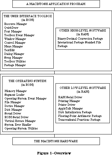 Figure 1–Overview
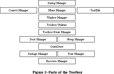 Figure 2–Parts of the Toolbox
Graphics are an important part of every Macintosh application. All graphic operations on the Macintosh are performed by QuickDraw. To draw something on the screen, you’ll often call one of the other parts of the Toolbox, but it will in turn call QuickDraw. You’ll also call QuickDraw directly, usually to draw inside a window, or just to set up constructs like rectangles that you’ll need when making other Toolbox calls. QuickDraw’s underlying concepts, like those of the Resource Manager, are important for you to understand.
Graphics include text as well as pictures. To draw text, QuickDraw calls the Font Manager, which does the background work necessary to make a variety of character fonts available in various sizes and styles. Unless your application includes a font menu, you need to know only a minimal amount about the Font Manager.
An application decides what to do from moment to moment by examining input from the user in the form of mouse and keyboard actions. It learns of such actions by repeatedly calling the Toolbox Event Manager (which in turn calls another, lower-level Event Manager in the Operating System). The Toolbox Event Manager also reports occurrences within the application that may require a response, such as when a window that was overlapped becomes exposed and needs to be redrawn.
All information presented by a standard Macintosh application appears in windows. To create windows, activate them, move them, resize them, or close them, you’ll call the Window Manager. It keeps track of overlapping windows, so you can manipulate windows without concern for how they overlap. For example, the Window Manager tells the Toolbox Event Manager when to inform your application that a window has to be redrawn. Also, when the user presses the mouse button, you call the Window Manager to learn which part of which window it was pressed in, or whether it was pressed in the menu bar or a desk accessory.
Any window may contain controls, such as buttons, check boxes, and scroll bars. You can create and manipulate controls with the Control Manager. When you learn from the Window Manager that the user pressed the mouse button inside a window containing controls, you call the Control Manager to find out which control it was pressed in, if any.
A common place for the user to press the mouse button is, of course, in the menu bar. You set up menus in the menu bar by calling the Menu Manager. When the user gives a command, either from a menu with the mouse or from the keyboard with the Command key, you call the Menu Manager to find out which command was given.
To accept text typed by the user and allow the standard editing capabilities, including cutting and pasting text within a document via the Clipboard, your application can call TextEdit. TextEdit also handles basic formatting such as word wraparound and justification. You can use it just to display text if you like.
When an application needs more information from the user about a command, it presents a dialog box. In case of errors or potentially dangerous situations, it alerts the user with a box containing a message or with sound from the Macintosh’s speaker (or both). To create and present dialogs and alerts, and find out the user’s responses to them, you call the Dialog Manager.
Every Macintosh application should support the use of desk accessories. The user opens desk accessories through the Apple menu, which you set up by calling the Menu Manager. When you learn that the user has pressed the mouse button in a desk accessory, you pass that information on to the accessory by calling the Desk Manager. The Desk Manager also includes routines that you must call to ensure that desk accessories work properly.
As mentioned above, you can use TextEdit to implement the standard text editing capability of cutting and pasting via the Clipboard in your application. To allow the use of the Clipboard for cutting and pasting text or graphics between your application and another application or a desk accessory, you need to call the Scrap Manager.
Some generally useful operations such as fixed-point arithmetic, string manipulation, and logical operations on bits may be performed with the Toolbox Utilities.
The final part of the Toolbox, the Package Manager, lets you use RAM-based software called packages. The Standard File Package will be called by every application whose File menu includes the standard commands for saving and opening documents; it presents the standard user interface for specifying the document. Two of the Macintosh packages can be seen as extensions to the Toolbox Utilities: The Binary-Decimal Conversion Package converts integers to decimal strings and vice versa, and the International Utilities Package gives you access to country-dependent information such as the formats for numbers, currency, dates, and times.
_______________________________________________________________________________
»The Operating System and Other Low-Level Software
The Macintosh Operating System provides the low-level support that applications need in order to use the Macintosh hardware. As the Toolbox is your program’s interface to the user, the Operating System is its interface to the Macintosh.
The Memory Manager dynamically allocates and releases memory for use by applications and by the other parts of the Operating System. Most of the memory that your program uses is in an area called the heap; the code of the program itself occupies space in the heap. Memory space in the heap must be obtained through the Memory Manager.
The Segment Loader is the part of the Operating System that loads application code into memory to be executed. Your application can be loaded all at once, or you can divide it up into dynamically loaded segments to economize on memory usage. The Segment Loader also serves as a bridge between the Finder and your application, letting you know whether the application has to open or print a document on the desktop when it starts up.
Low-level, hardware-related events such as mouse-button presses and keystrokes are reported by the Operating System Event Manager. (The Toolbox Event Manager then passes them to the application, along with higher-level, software-generated events added at the Toolbox level.) Your program will ordinarily deal only with the Toolbox Event Manager and will rarely call the Operating System Event Manager directly.
File I/O is supported by the File Manager, and device I/O by the Device Manager. The task of making the various types of devices present the same interface to the application is performed by specialized device drivers. The Operating System includes three built-in drivers:
• The Disk Driver controls data storage and retrieval on 3 1/2-inch disks.
• The Sound Driver controls sound generation, including music composed
of up to four simultaneous tones.
• The Serial Driver reads and writes asynchronous data through the two
serial ports, providing communication between applications and serial
peripheral devices such as a modem or printer.
The above drivers are all in ROM; other drivers are RAM-based. There’s a Serial Driver in RAM as well as the one in ROM, and there’s a Printer Driver in RAM that enables applications to print information on any variety of printer via the same interface (called the Printing Manager). The AppleTalk Manager is an interface to a pair of RAM drivers that enable programs to send and receive information via an AppleTalk network. More RAM drivers can be added independently or built on the existing drivers (by calling the routines in those drivers). For example, the Printer Driver was built on the Serial Driver, and a music driver could be built on the Sound Driver.
The Macintosh video circuitry generates a vertical retrace interrupt 60 times a second. An application can schedule routines to be executed at regular intervals based on this “heartbeat” of the system. The Vertical Retrace Manager handles the scheduling and execution of tasks during the vertical retrace interrupt.
If a fatal system error occurs while your application is running, the System Error Handler assumes control. The System Error Handler displays a box containing an error message and provides a mechanism for the user to start up the system again or resume execution of the application.
The Operating System Utilities perform miscellaneous operations such as getting the date and time, finding out the user’s preferred speaker volume and other preferences, and doing simple string comparison. (More sophisticated string comparison routines are available in the International Utilities Package.)
Finally, there are three Macintosh packages that perform low-level operations:
the Disk Initialization Package, which the Standard File Package calls to initialize and name disks; the Floating-Point Arithmetic Package, which supports extended-precision arithmetic according to IEEE Standard 754; and the Transcendental Functions Package, which contains trigonometric, logarithmic, exponential, and financial functions, as well as a random number generator.
_______________________________________________________________________________
»A SIMPLE EXAMPLE PROGRAM
_______________________________________________________________________________
To illustrate various commonly used parts of the software, this section presents an extremely simple example of a Macintosh application program. Though too simple to be practical, this example shows the overall structure that every application program will have, and it does many of the basic things every application will do. By looking it over, you can become more familiar with the software and see how your own program code will be structured.
The example program’s source code is shown at the end of this chapter, which begins at the end of this section. A lot of comments are included so that you can see which part of the Toolbox or Operating System is being called and what operation is being performed. These comments, and those that follow below, may contain terms that are unfamiliar to you, but for now just read along to get the general idea. All the terms are explained at length within Inside Macintosh. If you want more information right away, you can look up the terms in the Glossary or the Index.
The application, called Sample, displays a single, fixed-size window in which the user can enter and edit text (see Figure 3). It has three menus: the standard Apple menu, from which desk accessories can be chosen; a File menu, containing only a Quit command; and an Edit menu, containing the standard editing commands Undo, Cut, Copy, Paste, and Clear. The Edit menu also includes the standard keyboard equivalents for Undo, Cut, Copy, and Paste: Command-Z,
X, C, and V, respectively. The Backspace key may be used to delete, and Shift-clicking will extend or shorten a selection. The user can move the document window around the desktop by dragging it by its title bar.
Figure 2–Parts of the Toolbox
Graphics are an important part of every Macintosh application. All graphic operations on the Macintosh are performed by QuickDraw. To draw something on the screen, you’ll often call one of the other parts of the Toolbox, but it will in turn call QuickDraw. You’ll also call QuickDraw directly, usually to draw inside a window, or just to set up constructs like rectangles that you’ll need when making other Toolbox calls. QuickDraw’s underlying concepts, like those of the Resource Manager, are important for you to understand.
Graphics include text as well as pictures. To draw text, QuickDraw calls the Font Manager, which does the background work necessary to make a variety of character fonts available in various sizes and styles. Unless your application includes a font menu, you need to know only a minimal amount about the Font Manager.
An application decides what to do from moment to moment by examining input from the user in the form of mouse and keyboard actions. It learns of such actions by repeatedly calling the Toolbox Event Manager (which in turn calls another, lower-level Event Manager in the Operating System). The Toolbox Event Manager also reports occurrences within the application that may require a response, such as when a window that was overlapped becomes exposed and needs to be redrawn.
All information presented by a standard Macintosh application appears in windows. To create windows, activate them, move them, resize them, or close them, you’ll call the Window Manager. It keeps track of overlapping windows, so you can manipulate windows without concern for how they overlap. For example, the Window Manager tells the Toolbox Event Manager when to inform your application that a window has to be redrawn. Also, when the user presses the mouse button, you call the Window Manager to learn which part of which window it was pressed in, or whether it was pressed in the menu bar or a desk accessory.
Any window may contain controls, such as buttons, check boxes, and scroll bars. You can create and manipulate controls with the Control Manager. When you learn from the Window Manager that the user pressed the mouse button inside a window containing controls, you call the Control Manager to find out which control it was pressed in, if any.
A common place for the user to press the mouse button is, of course, in the menu bar. You set up menus in the menu bar by calling the Menu Manager. When the user gives a command, either from a menu with the mouse or from the keyboard with the Command key, you call the Menu Manager to find out which command was given.
To accept text typed by the user and allow the standard editing capabilities, including cutting and pasting text within a document via the Clipboard, your application can call TextEdit. TextEdit also handles basic formatting such as word wraparound and justification. You can use it just to display text if you like.
When an application needs more information from the user about a command, it presents a dialog box. In case of errors or potentially dangerous situations, it alerts the user with a box containing a message or with sound from the Macintosh’s speaker (or both). To create and present dialogs and alerts, and find out the user’s responses to them, you call the Dialog Manager.
Every Macintosh application should support the use of desk accessories. The user opens desk accessories through the Apple menu, which you set up by calling the Menu Manager. When you learn that the user has pressed the mouse button in a desk accessory, you pass that information on to the accessory by calling the Desk Manager. The Desk Manager also includes routines that you must call to ensure that desk accessories work properly.
As mentioned above, you can use TextEdit to implement the standard text editing capability of cutting and pasting via the Clipboard in your application. To allow the use of the Clipboard for cutting and pasting text or graphics between your application and another application or a desk accessory, you need to call the Scrap Manager.
Some generally useful operations such as fixed-point arithmetic, string manipulation, and logical operations on bits may be performed with the Toolbox Utilities.
The final part of the Toolbox, the Package Manager, lets you use RAM-based software called packages. The Standard File Package will be called by every application whose File menu includes the standard commands for saving and opening documents; it presents the standard user interface for specifying the document. Two of the Macintosh packages can be seen as extensions to the Toolbox Utilities: The Binary-Decimal Conversion Package converts integers to decimal strings and vice versa, and the International Utilities Package gives you access to country-dependent information such as the formats for numbers, currency, dates, and times.
_______________________________________________________________________________
»The Operating System and Other Low-Level Software
The Macintosh Operating System provides the low-level support that applications need in order to use the Macintosh hardware. As the Toolbox is your program’s interface to the user, the Operating System is its interface to the Macintosh.
The Memory Manager dynamically allocates and releases memory for use by applications and by the other parts of the Operating System. Most of the memory that your program uses is in an area called the heap; the code of the program itself occupies space in the heap. Memory space in the heap must be obtained through the Memory Manager.
The Segment Loader is the part of the Operating System that loads application code into memory to be executed. Your application can be loaded all at once, or you can divide it up into dynamically loaded segments to economize on memory usage. The Segment Loader also serves as a bridge between the Finder and your application, letting you know whether the application has to open or print a document on the desktop when it starts up.
Low-level, hardware-related events such as mouse-button presses and keystrokes are reported by the Operating System Event Manager. (The Toolbox Event Manager then passes them to the application, along with higher-level, software-generated events added at the Toolbox level.) Your program will ordinarily deal only with the Toolbox Event Manager and will rarely call the Operating System Event Manager directly.
File I/O is supported by the File Manager, and device I/O by the Device Manager. The task of making the various types of devices present the same interface to the application is performed by specialized device drivers. The Operating System includes three built-in drivers:
• The Disk Driver controls data storage and retrieval on 3 1/2-inch disks.
• The Sound Driver controls sound generation, including music composed
of up to four simultaneous tones.
• The Serial Driver reads and writes asynchronous data through the two
serial ports, providing communication between applications and serial
peripheral devices such as a modem or printer.
The above drivers are all in ROM; other drivers are RAM-based. There’s a Serial Driver in RAM as well as the one in ROM, and there’s a Printer Driver in RAM that enables applications to print information on any variety of printer via the same interface (called the Printing Manager). The AppleTalk Manager is an interface to a pair of RAM drivers that enable programs to send and receive information via an AppleTalk network. More RAM drivers can be added independently or built on the existing drivers (by calling the routines in those drivers). For example, the Printer Driver was built on the Serial Driver, and a music driver could be built on the Sound Driver.
The Macintosh video circuitry generates a vertical retrace interrupt 60 times a second. An application can schedule routines to be executed at regular intervals based on this “heartbeat” of the system. The Vertical Retrace Manager handles the scheduling and execution of tasks during the vertical retrace interrupt.
If a fatal system error occurs while your application is running, the System Error Handler assumes control. The System Error Handler displays a box containing an error message and provides a mechanism for the user to start up the system again or resume execution of the application.
The Operating System Utilities perform miscellaneous operations such as getting the date and time, finding out the user’s preferred speaker volume and other preferences, and doing simple string comparison. (More sophisticated string comparison routines are available in the International Utilities Package.)
Finally, there are three Macintosh packages that perform low-level operations:
the Disk Initialization Package, which the Standard File Package calls to initialize and name disks; the Floating-Point Arithmetic Package, which supports extended-precision arithmetic according to IEEE Standard 754; and the Transcendental Functions Package, which contains trigonometric, logarithmic, exponential, and financial functions, as well as a random number generator.
_______________________________________________________________________________
»A SIMPLE EXAMPLE PROGRAM
_______________________________________________________________________________
To illustrate various commonly used parts of the software, this section presents an extremely simple example of a Macintosh application program. Though too simple to be practical, this example shows the overall structure that every application program will have, and it does many of the basic things every application will do. By looking it over, you can become more familiar with the software and see how your own program code will be structured.
The example program’s source code is shown at the end of this chapter, which begins at the end of this section. A lot of comments are included so that you can see which part of the Toolbox or Operating System is being called and what operation is being performed. These comments, and those that follow below, may contain terms that are unfamiliar to you, but for now just read along to get the general idea. All the terms are explained at length within Inside Macintosh. If you want more information right away, you can look up the terms in the Glossary or the Index.
The application, called Sample, displays a single, fixed-size window in which the user can enter and edit text (see Figure 3). It has three menus: the standard Apple menu, from which desk accessories can be chosen; a File menu, containing only a Quit command; and an Edit menu, containing the standard editing commands Undo, Cut, Copy, Paste, and Clear. The Edit menu also includes the standard keyboard equivalents for Undo, Cut, Copy, and Paste: Command-Z,
X, C, and V, respectively. The Backspace key may be used to delete, and Shift-clicking will extend or shorten a selection. The user can move the document window around the desktop by dragging it by its title bar.
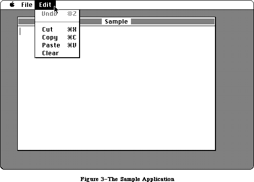 Figure 3–The Sample Application
The Undo command doesn’t work in the application’s document window, but it and all the other editing commands do work in any desk accessories that allow them
(the Note Pad, for example). Some standard features this simple example doesn’t support are as follows:
• Text cannot be cut (or copied) and pasted between the document
and a desk accessory.
• The pointer remains an arrow rather than changing to an I-beam
within the document.
• Except for Undo, editing commands aren’t dimmed when they don’t
apply (for example, Cut or Copy when there’s no text selection).
The document window can’t be closed, scrolled, or resized. Because the File menu contains only a Quit command, the document can’t be saved or printed. Also, the application doesn’t have “About Sample...” as the first command in its Apple menu, or a Hide/Show Clipboard command in its Edit menu (for displaying cut or copied text).
In addition to the code shown at the end of this chapter, the Sample application has a resource file that includes the data listed below. The program uses the numbers in the second column to identify the resources; for example, it makes a Menu Manager call to get menu number 128 from the resource file.
Resource Resource ID Description
Menu 128 Menu with the apple symbol as its title
and no commands in it
Menu 129 File menu with one command, Quit, with
keyboard equivalent Command-Q
Menu 130 Edit menu with the commands Undo (dimmed),
Cut, Copy, Paste, and Clear, in that order,
with the standard keyboard equivalents and
with a dividing line between Undo and Cut
Window 128 Document window without a size box;
template top left corner of (50,40) on QuickDraw’s
coordinate plane, bottom right corner of
(300,450); title “Sample”; no close box
Each menu resource also contains a “menu ID” that’s used to identify the menu when the user chooses a command from it; for all three menus, this ID is the same as the resource ID.
Note: To create a resource file with the above contents, you can use the
Resource Editor or any similar program that may be available on the
development system you’re using.
The program starts with a USES clause that specifies all the necessary Pascal interface files. (The names shown are for the Lisa Workshop development system, and may be different for other systems.) This is followed by declarations of some useful constants, to make the source code more readable. Then there are a number of variable declarations, some having simple Pascal data types and others with data types defined in the interface files (like Rect and WindowPtr). Variables used in the program that aren’t declared here are global variables defined in the interface to QuickDraw.
The variable declarations are followed by two procedure declarations: SetUpMenus and DoCommand. You can understand them better after looking at the main program and seeing where they’re called.
The program begins with a standard initialization sequence. Every application will need to do this same initialization (in the order shown), or something close to it.
Additional initialization needed by the program follows. This includes setting up the menus and the menu bar (by calling SetUpMenus) and creating the application’s document window (reading its description from the resource file and displaying it on the screen).
The heart of every application program is its main event loop, which repeatedly calls the Toolbox Event Manager to get events and then responds to them as appropriate. The most common event is a press of the mouse button; depending on where it was pressed, as reported by the Window Manager, the sample program may execute a command, move the document window, make the window active, or pass the event on to a desk accessory. The DoCommand procedure takes care of executing a command; it looks at information received by the Menu Manager to determine which command to execute.
Besides events resulting directly from user actions such as pressing the mouse button or a key on the keyboard, events are detected by the Window Manager as a side effect of those actions. For example, when a window changes from active to inactive or vice versa, the Window Manager tells the Toolbox Event Manager to report it to the application program. A similar process happens when all or part of a window needs to be updated (redrawn). The internal mechanism in each case is invisible to the program, which simply responds to the event when notified.
The main event loop terminates when the user takes some action to leave the program—in this case, when the Quit command is chosen.
That’s it! Of course, the program structure and level of detail will get more complicated as the application becomes more complex, and every actual application will be more complex than this one. But each will be based on the structure illustrated here.
PROGRAM Sample;
{ Sample -- A small sample application written by Macintosh User }
{ Education. It displays a single, fixed-size window in which the }
{ user can enter and edit text. }
{ The following two compiler commands are required }
{ for the Lisa Workshop. }
{$X-} {turn off automatic stack expansion}
{$U-} {turn off Lisa libraries}
{ The USES clause brings in the units containing the Pascal interfaces. }
{ The $U expression tells the compiler what file to look in for the }
{ specified unit. }
USES {$U Obj/MemTypes } MemTypes, {basic Memory Manager data types}
{$U Obj/QuickDraw} QuickDraw, {interface to QuickDraw}
{$U Obj/OSIntf } OSIntf, {interface to the Operating System}
{$U Obj/ToolIntf } ToolIntf; {interface to the Toolbox}
CONST
appleID = 128; {resource IDs/menu IDs for Apple, File, and Edit menus}
fileID = 129;
editID = 130;
appleM = l; {index for each menu in myMenus (array of menu handles)}
fileM = 2;
editM = 3;
menuCount = 3; {total number of menus}
windowID = 128; {resource ID for application's window}
undoCommand = l; {menu item numbers identifying commands in Edit menu}
cutCommand = 3;
copyCommand = 4;
pasteCommand = 5;
clearCommand = 6;
VAR
myMenus: ARRAY [l..menuCount] OF MenuHandle; {array of handles to the menus}
dragRect: Rect; {rectangle used to mark boundaries for}
{dragging window}
txRect: Rect; {rectangle for text in application window}
textH: TEHandle; {handle to information about the text}
theChar: CHAR; {character typed on the keyboard or keypad}
extended: BOOLEAN; {TRUE if user is Shift-clicking}
doneFlag: BOOLEAN; {TRUE if user has chosen Quit command}
myEvent: EventRecord; {information about an event}
wRecord: WindowRecord; {information about the application window}
myWindow: WindowPtr; {pointer to wRecord}
whichWindow: WindowPtr; {pointer to window in which mouse button}
{was pressed}
PROCEDURE SetUpMenus;
{ Set up menus and menu bar }
VAR
i: INTEGER;
BEGIN
{ Read menu descriptions from resource file into memory and store handles }
{ in myMenus array }
myMenus[appleM] := GetMenu(appleID); {read Apple menu from resource file}
AddResMenu(myMenus[appleM], 'DRVR'); {add desk accessory names to}
{Apple menu}
myMenus[fileM] := GetMenu(fileID); {read File menu from resource file}
myMenus[editM] := GetMenu(editID); {read Edit menu from resource file}
FOR i := l TO menuCount DO InsertMenu(myMenus[i], O); {install menus in}
{menu bar }
DrawMenuBar; {and draw menu bar}
END; {of SetUpMenu}
PROCEDURE DoCommand(mResult: LONGINT);
{ Execute command specified by mResult, the result of MenuSelect }
VAR
theItem: INTEGER; {menu item number from mResult low-order word)
theMenu: INTEGER; {menu number from mResult high-order word}
name: Str255; {desk accessory name}
temp: INTEGER;
BEGIN
theItem := LoWord(mResult); {call Toolbox Utility routines to set }
theMenu := HiWord(mResult); { menu item number and menu number}
CASE theMenu OF {case on menu ID}
appleID:
BEGIN {call Menu Manager to get desk accessory }
GetItem(myMenus[appleM], theItem, name); { name, and call Desk }
{ Manager to open }
temp := OpenDeskAcc(name); { accessory (OpenDeskAcc
{ result not used)}
SetPort(myWindow); {call QuickDraw to restore application }
END; {of appleID} { window as grafPort to draw in (may have }
{ been changed during OpenDeskAccc) }
fileID: doneFlag := TRUE; {quit (main loop repeats until}
{doneFlag is TRUE)}
editID:
BEGIN {call Desk Manager to handle editing}
{command if desk accessory window is}
IF NOT SystemEdit(theItem - 1) { the active window}
THEN {application window is the active window}
CASE theItem OF {case on menu item (command) number}
cutCommand: TECut(textH); {call TextEdit to handle command}
copyCommand: TECopy(textH);
pasteCommand: TEPaste(textH);
clearCommand: TEDelete(textH);
END; {of item case}
END; {of editID}
END; {of menu case} {to indicate completion of command, call }
HiliteMenu(O); { Menu Manager to unhighlight menu title }
{ (highlighted by MenuSelect) }
END; {of DoCommand}
BEGIN {main program}
{ Initialization }
InitGraf(@thePort); {initialize QuickDraw}
InitFonts; {initialize Font Manager}
FlushEvents(everyEvent, O); {call OS Event Manager to discard}
{ any previous events}
InitWindows; {initialize Window Manager}
InitMenus; {initialize Menu Manager}
TEInit; {initialize TextEdit}
InitDialogs(NIL); {initialize Dialog Manager}
InitCursor; {call QuickDraw to make cursor (pointer)}
{ an arrow}
SetUpMenus; {set up menus and menu bar}
WITH screenBits.bounds DO {call QuickDraw to set dragging boundaries;}
{ ensure at least 4 by 4 pixels will remain}
SetRect(dragRect, 4, 24, right - 4, bottom - 4); { visible}
doneFlag := FALSE; {flag to detect when Quit command is chosen}
myWindow := GetNewWindow(windowID, @wRecord, POINTER( - l)); {put up }
{application}
{window}
SetPort(myWindow); {call QuickDraw to set current grafPort }
{ to this window rectangle for text in}
txRect := thePort^.portRect; { window; call QuickDraw to bring }
InsetRect(txRect, 4, 0); { it in 4 pixels from left and right }
{ edges of window }
textH := TENew(txRect, txRect); {call TextEdit to prepare for }
{ receiving text}
{ Main event loop }
REPEAT {call Desk Manager to perform any periodic ) SystemTask;
{ actions defined for desk accessories}
TEIdle(textH); {call TextEdit to make vertical bar blink}
IF GetNextEvent(everyEvent, myEvent)
{call Toolbox Event Manager to get the next }
THEN { event that the application should handle}
CASE myEvent.what OF {case on event type}
mouseDown: {mouse button down: call Window Manager}
{ to learn where}
CASE FindWindow(myEvent.where, whichWindow) OF
inSysWindow: {desk accessory window: call Desk Manager}
{to handle it}
SystemClick {myEvent,whichWindow); inMenuBar:
{menu bar: call Menu Manager to learn }
{ which command, then execute it }
DoCommand(MenuSelect(myEvent.where));
inDrag: {title bar: call Window Manager to drag}
DragWindow(whichWindow, myEvent.where, dragRect);
inContent: {body of application window: }
BEGIN { call Window Manager to check whether }
IF whichWindow <> FrontWindow
{ it's the active window and make it }
THEN
SelectWindow(whichWindow) { active if not}
ELSE
BEGIN {it's already active: call QuickDraw to }
{ convert to window coordinates for }
{ TEClick, use Toolbox Utility BitAnd to}
{ test for Shift }
GlobalToLocal(myEvent.where);
extended := BitAnd(myEvent.modifiers, shiftKey) <> O;
TEClick(myEvent.where, extended, textH);
{ key down, and call TextEdit}
END; { to process the event}
END; {of inContent}
END; {of mouseDown}
keyDown, autoKey: {key pressed once or held down to repeat}
BEGIN
theChar := CHR(BitAnd(myEvent.message, charCodeMask));
{get the character}
IF BitAnd(myEvent.modifiers, cmdKey) <> 0
THEN {if Command key down, call Menu }
DoCommand(MenuKey(theChar)) { Manager to learn which command,}
ELSE { then execute it; else pass }
TEKey(theChar, textH); { character to TextEdit}
END;
activateEvt:
BEGIN
IF BitAnd(myEvent.modifiers, activeFlag) <> 0 THEN
{application window is becoming active:}
BEGIN { call TextEdit to highlight selection}
TEActivate(textH);
{ or display blinking vertical bar, and call}
DisableItem(myMenus[editM], undoCommand);
{ Menu Manager to disable Undo}
END {(since application doesn't support Undo)}
ELSE
BEGIN {application window is becoming inactive: }
TEDeactivate(textH);
{ unhighlight selection or remove blinking}
{ vertical bar, and enable Undo (since desk}
{ accessory may support it)}
EnableItem(myMenus[editM], undoCommand);
END;
END; {of activateEvt}
updateEvt: {window appearance needs updating}
BEGIN
BeginUpdate(WindowPtr(myEvent.message));
{call Window Manager to begin update}
EraseRect(thePort^.portRect);
{Call QuickDraw to erase text area}
TEUpdate(thePort^.portRect, textH);
{call TextEdit to update the text}
EndUpdate(WindowPtr(myEvent.message));
{call Window Manager to end update}
END; {of updateEvt}
END; {of event case}
UNTIL doneFlag;
END.
_______________________________________________________________________________
»WHERE TO GO FROM HERE
_______________________________________________________________________________
This section contains important directions for every reader of Inside Macintosh. It will help you figure out which chapters to read next.
The Inside Macintosh chapters are ordered in such a way that you can follow it if you read through it sequentially. Forward references are given wherever necessary to any additional information that you’ll need in order to fully understand what’s being discussed. Special-purpose information that can possibly be skipped is indicated as such. Most likely you won’t need to read everything in each chapter and can even skip entire chapters.
You should begin by reading the following chapters:
1. The Macintosh User Interface Guidelines. All Macintosh
applications should follow these guidelines to ensure that the end
user is presented with a consistent, familiar interface.
2. Macintosh Memory Management: An Introduction.
3. Using Assembly Language, if you’re programming in assembly language.
Depending on the debugging tools available on the development
system you’re using, it may also be helpful or necessary for high-level
language programmers to read this chapter. You’ll also have to read it
if you’re creating your own development system and want to know how to
write interfaces to the routines.
4. The chapters describing the parts of the Toolbox that deal with the
fundamental aspects of the user interface: the Resource Manager,
QuickDraw, the Toolbox Event Manager, the Window Manager, and the
Menu Manager.
Read the other chapters if you’re interested in what they discuss, which you should be able to tell from the overviews in this “road map” and from the introductions to the chapters themselves. Each chapter’s introduction will also tell you what you should already know before reading that chapter.
When you’re ready to try something out, refer to the appropriate documentation for the development system you’ll be using.
Figure 3–The Sample Application
The Undo command doesn’t work in the application’s document window, but it and all the other editing commands do work in any desk accessories that allow them
(the Note Pad, for example). Some standard features this simple example doesn’t support are as follows:
• Text cannot be cut (or copied) and pasted between the document
and a desk accessory.
• The pointer remains an arrow rather than changing to an I-beam
within the document.
• Except for Undo, editing commands aren’t dimmed when they don’t
apply (for example, Cut or Copy when there’s no text selection).
The document window can’t be closed, scrolled, or resized. Because the File menu contains only a Quit command, the document can’t be saved or printed. Also, the application doesn’t have “About Sample...” as the first command in its Apple menu, or a Hide/Show Clipboard command in its Edit menu (for displaying cut or copied text).
In addition to the code shown at the end of this chapter, the Sample application has a resource file that includes the data listed below. The program uses the numbers in the second column to identify the resources; for example, it makes a Menu Manager call to get menu number 128 from the resource file.
Resource Resource ID Description
Menu 128 Menu with the apple symbol as its title
and no commands in it
Menu 129 File menu with one command, Quit, with
keyboard equivalent Command-Q
Menu 130 Edit menu with the commands Undo (dimmed),
Cut, Copy, Paste, and Clear, in that order,
with the standard keyboard equivalents and
with a dividing line between Undo and Cut
Window 128 Document window without a size box;
template top left corner of (50,40) on QuickDraw’s
coordinate plane, bottom right corner of
(300,450); title “Sample”; no close box
Each menu resource also contains a “menu ID” that’s used to identify the menu when the user chooses a command from it; for all three menus, this ID is the same as the resource ID.
Note: To create a resource file with the above contents, you can use the
Resource Editor or any similar program that may be available on the
development system you’re using.
The program starts with a USES clause that specifies all the necessary Pascal interface files. (The names shown are for the Lisa Workshop development system, and may be different for other systems.) This is followed by declarations of some useful constants, to make the source code more readable. Then there are a number of variable declarations, some having simple Pascal data types and others with data types defined in the interface files (like Rect and WindowPtr). Variables used in the program that aren’t declared here are global variables defined in the interface to QuickDraw.
The variable declarations are followed by two procedure declarations: SetUpMenus and DoCommand. You can understand them better after looking at the main program and seeing where they’re called.
The program begins with a standard initialization sequence. Every application will need to do this same initialization (in the order shown), or something close to it.
Additional initialization needed by the program follows. This includes setting up the menus and the menu bar (by calling SetUpMenus) and creating the application’s document window (reading its description from the resource file and displaying it on the screen).
The heart of every application program is its main event loop, which repeatedly calls the Toolbox Event Manager to get events and then responds to them as appropriate. The most common event is a press of the mouse button; depending on where it was pressed, as reported by the Window Manager, the sample program may execute a command, move the document window, make the window active, or pass the event on to a desk accessory. The DoCommand procedure takes care of executing a command; it looks at information received by the Menu Manager to determine which command to execute.
Besides events resulting directly from user actions such as pressing the mouse button or a key on the keyboard, events are detected by the Window Manager as a side effect of those actions. For example, when a window changes from active to inactive or vice versa, the Window Manager tells the Toolbox Event Manager to report it to the application program. A similar process happens when all or part of a window needs to be updated (redrawn). The internal mechanism in each case is invisible to the program, which simply responds to the event when notified.
The main event loop terminates when the user takes some action to leave the program—in this case, when the Quit command is chosen.
That’s it! Of course, the program structure and level of detail will get more complicated as the application becomes more complex, and every actual application will be more complex than this one. But each will be based on the structure illustrated here.
PROGRAM Sample;
{ Sample -- A small sample application written by Macintosh User }
{ Education. It displays a single, fixed-size window in which the }
{ user can enter and edit text. }
{ The following two compiler commands are required }
{ for the Lisa Workshop. }
{$X-} {turn off automatic stack expansion}
{$U-} {turn off Lisa libraries}
{ The USES clause brings in the units containing the Pascal interfaces. }
{ The $U expression tells the compiler what file to look in for the }
{ specified unit. }
USES {$U Obj/MemTypes } MemTypes, {basic Memory Manager data types}
{$U Obj/QuickDraw} QuickDraw, {interface to QuickDraw}
{$U Obj/OSIntf } OSIntf, {interface to the Operating System}
{$U Obj/ToolIntf } ToolIntf; {interface to the Toolbox}
CONST
appleID = 128; {resource IDs/menu IDs for Apple, File, and Edit menus}
fileID = 129;
editID = 130;
appleM = l; {index for each menu in myMenus (array of menu handles)}
fileM = 2;
editM = 3;
menuCount = 3; {total number of menus}
windowID = 128; {resource ID for application's window}
undoCommand = l; {menu item numbers identifying commands in Edit menu}
cutCommand = 3;
copyCommand = 4;
pasteCommand = 5;
clearCommand = 6;
VAR
myMenus: ARRAY [l..menuCount] OF MenuHandle; {array of handles to the menus}
dragRect: Rect; {rectangle used to mark boundaries for}
{dragging window}
txRect: Rect; {rectangle for text in application window}
textH: TEHandle; {handle to information about the text}
theChar: CHAR; {character typed on the keyboard or keypad}
extended: BOOLEAN; {TRUE if user is Shift-clicking}
doneFlag: BOOLEAN; {TRUE if user has chosen Quit command}
myEvent: EventRecord; {information about an event}
wRecord: WindowRecord; {information about the application window}
myWindow: WindowPtr; {pointer to wRecord}
whichWindow: WindowPtr; {pointer to window in which mouse button}
{was pressed}
PROCEDURE SetUpMenus;
{ Set up menus and menu bar }
VAR
i: INTEGER;
BEGIN
{ Read menu descriptions from resource file into memory and store handles }
{ in myMenus array }
myMenus[appleM] := GetMenu(appleID); {read Apple menu from resource file}
AddResMenu(myMenus[appleM], 'DRVR'); {add desk accessory names to}
{Apple menu}
myMenus[fileM] := GetMenu(fileID); {read File menu from resource file}
myMenus[editM] := GetMenu(editID); {read Edit menu from resource file}
FOR i := l TO menuCount DO InsertMenu(myMenus[i], O); {install menus in}
{menu bar }
DrawMenuBar; {and draw menu bar}
END; {of SetUpMenu}
PROCEDURE DoCommand(mResult: LONGINT);
{ Execute command specified by mResult, the result of MenuSelect }
VAR
theItem: INTEGER; {menu item number from mResult low-order word)
theMenu: INTEGER; {menu number from mResult high-order word}
name: Str255; {desk accessory name}
temp: INTEGER;
BEGIN
theItem := LoWord(mResult); {call Toolbox Utility routines to set }
theMenu := HiWord(mResult); { menu item number and menu number}
CASE theMenu OF {case on menu ID}
appleID:
BEGIN {call Menu Manager to get desk accessory }
GetItem(myMenus[appleM], theItem, name); { name, and call Desk }
{ Manager to open }
temp := OpenDeskAcc(name); { accessory (OpenDeskAcc
{ result not used)}
SetPort(myWindow); {call QuickDraw to restore application }
END; {of appleID} { window as grafPort to draw in (may have }
{ been changed during OpenDeskAccc) }
fileID: doneFlag := TRUE; {quit (main loop repeats until}
{doneFlag is TRUE)}
editID:
BEGIN {call Desk Manager to handle editing}
{command if desk accessory window is}
IF NOT SystemEdit(theItem - 1) { the active window}
THEN {application window is the active window}
CASE theItem OF {case on menu item (command) number}
cutCommand: TECut(textH); {call TextEdit to handle command}
copyCommand: TECopy(textH);
pasteCommand: TEPaste(textH);
clearCommand: TEDelete(textH);
END; {of item case}
END; {of editID}
END; {of menu case} {to indicate completion of command, call }
HiliteMenu(O); { Menu Manager to unhighlight menu title }
{ (highlighted by MenuSelect) }
END; {of DoCommand}
BEGIN {main program}
{ Initialization }
InitGraf(@thePort); {initialize QuickDraw}
InitFonts; {initialize Font Manager}
FlushEvents(everyEvent, O); {call OS Event Manager to discard}
{ any previous events}
InitWindows; {initialize Window Manager}
InitMenus; {initialize Menu Manager}
TEInit; {initialize TextEdit}
InitDialogs(NIL); {initialize Dialog Manager}
InitCursor; {call QuickDraw to make cursor (pointer)}
{ an arrow}
SetUpMenus; {set up menus and menu bar}
WITH screenBits.bounds DO {call QuickDraw to set dragging boundaries;}
{ ensure at least 4 by 4 pixels will remain}
SetRect(dragRect, 4, 24, right - 4, bottom - 4); { visible}
doneFlag := FALSE; {flag to detect when Quit command is chosen}
myWindow := GetNewWindow(windowID, @wRecord, POINTER( - l)); {put up }
{application}
{window}
SetPort(myWindow); {call QuickDraw to set current grafPort }
{ to this window rectangle for text in}
txRect := thePort^.portRect; { window; call QuickDraw to bring }
InsetRect(txRect, 4, 0); { it in 4 pixels from left and right }
{ edges of window }
textH := TENew(txRect, txRect); {call TextEdit to prepare for }
{ receiving text}
{ Main event loop }
REPEAT {call Desk Manager to perform any periodic ) SystemTask;
{ actions defined for desk accessories}
TEIdle(textH); {call TextEdit to make vertical bar blink}
IF GetNextEvent(everyEvent, myEvent)
{call Toolbox Event Manager to get the next }
THEN { event that the application should handle}
CASE myEvent.what OF {case on event type}
mouseDown: {mouse button down: call Window Manager}
{ to learn where}
CASE FindWindow(myEvent.where, whichWindow) OF
inSysWindow: {desk accessory window: call Desk Manager}
{to handle it}
SystemClick {myEvent,whichWindow); inMenuBar:
{menu bar: call Menu Manager to learn }
{ which command, then execute it }
DoCommand(MenuSelect(myEvent.where));
inDrag: {title bar: call Window Manager to drag}
DragWindow(whichWindow, myEvent.where, dragRect);
inContent: {body of application window: }
BEGIN { call Window Manager to check whether }
IF whichWindow <> FrontWindow
{ it's the active window and make it }
THEN
SelectWindow(whichWindow) { active if not}
ELSE
BEGIN {it's already active: call QuickDraw to }
{ convert to window coordinates for }
{ TEClick, use Toolbox Utility BitAnd to}
{ test for Shift }
GlobalToLocal(myEvent.where);
extended := BitAnd(myEvent.modifiers, shiftKey) <> O;
TEClick(myEvent.where, extended, textH);
{ key down, and call TextEdit}
END; { to process the event}
END; {of inContent}
END; {of mouseDown}
keyDown, autoKey: {key pressed once or held down to repeat}
BEGIN
theChar := CHR(BitAnd(myEvent.message, charCodeMask));
{get the character}
IF BitAnd(myEvent.modifiers, cmdKey) <> 0
THEN {if Command key down, call Menu }
DoCommand(MenuKey(theChar)) { Manager to learn which command,}
ELSE { then execute it; else pass }
TEKey(theChar, textH); { character to TextEdit}
END;
activateEvt:
BEGIN
IF BitAnd(myEvent.modifiers, activeFlag) <> 0 THEN
{application window is becoming active:}
BEGIN { call TextEdit to highlight selection}
TEActivate(textH);
{ or display blinking vertical bar, and call}
DisableItem(myMenus[editM], undoCommand);
{ Menu Manager to disable Undo}
END {(since application doesn't support Undo)}
ELSE
BEGIN {application window is becoming inactive: }
TEDeactivate(textH);
{ unhighlight selection or remove blinking}
{ vertical bar, and enable Undo (since desk}
{ accessory may support it)}
EnableItem(myMenus[editM], undoCommand);
END;
END; {of activateEvt}
updateEvt: {window appearance needs updating}
BEGIN
BeginUpdate(WindowPtr(myEvent.message));
{call Window Manager to begin update}
EraseRect(thePort^.portRect);
{Call QuickDraw to erase text area}
TEUpdate(thePort^.portRect, textH);
{call TextEdit to update the text}
EndUpdate(WindowPtr(myEvent.message));
{call Window Manager to end update}
END; {of updateEvt}
END; {of event case}
UNTIL doneFlag;
END.
_______________________________________________________________________________
»WHERE TO GO FROM HERE
_______________________________________________________________________________
This section contains important directions for every reader of Inside Macintosh. It will help you figure out which chapters to read next.
The Inside Macintosh chapters are ordered in such a way that you can follow it if you read through it sequentially. Forward references are given wherever necessary to any additional information that you’ll need in order to fully understand what’s being discussed. Special-purpose information that can possibly be skipped is indicated as such. Most likely you won’t need to read everything in each chapter and can even skip entire chapters.
You should begin by reading the following chapters:
1. The Macintosh User Interface Guidelines. All Macintosh
applications should follow these guidelines to ensure that the end
user is presented with a consistent, familiar interface.
2. Macintosh Memory Management: An Introduction.
3. Using Assembly Language, if you’re programming in assembly language.
Depending on the debugging tools available on the development
system you’re using, it may also be helpful or necessary for high-level
language programmers to read this chapter. You’ll also have to read it
if you’re creating your own development system and want to know how to
write interfaces to the routines.
4. The chapters describing the parts of the Toolbox that deal with the
fundamental aspects of the user interface: the Resource Manager,
QuickDraw, the Toolbox Event Manager, the Window Manager, and the
Menu Manager.
Read the other chapters if you’re interested in what they discuss, which you should be able to tell from the overviews in this “road map” and from the introductions to the chapters themselves. Each chapter’s introduction will also tell you what you should already know before reading that chapter.
When you’re ready to try something out, refer to the appropriate documentation for the development system you’ll be using.
Compatibility Guidelines
_______________________________________________________________________________
COMPATIBILITY GUIDELINES
_______________________________________________________________________________
About This Chapter
Compatibility
General Guidelines
Memory
Assembly Language
Hardware
Determining the Features of a Machine
Localization
¿Pero, Se Habla Español?
Non-Roman Writing Systems
Applications in a Shared Environment
Summary of Compatibility Guidelines
_______________________________________________________________________________
»ABOUT THIS CHAPTER
_______________________________________________________________________________
Compatibility is a concern for anyone writing software. For some programmers, it’s a concern because they want to write software that will run, with little or no modification, on all versions of the Macintosh. Other programmers want to take advantage of particular software and hardware features; they need to know where and when these features are available.
This chapter gives guidelines for making it more likely that your program will run on different versions, present and future, of the Macintosh. It also gives tips for writing software that can be easily modified for use in other countries. Finally, it explains how to determine what features are available on a given machine.
_______________________________________________________________________________
»COMPATIBILITY
_______________________________________________________________________________
The key to compatibility is not to depend on things that may change. Inside Macintosh contains hundreds of warnings where information is likely to change; all of these warnings can be summarized by a single rule: use global variable names and system calls, rather than addresses and numeric values.
At the most basic level, all of the software and hardware components of the Macintosh—each line of ROM code, each RAM memory location, each hardware device—are represented by numbers. Symbolic names have been defined for virtually every routine, variable, data structure, memory location, and hardware device that your application will need to use. Use of these names instead of the actual numbers will simplify the process of updating your application when the numbers change.
_______________________________________________________________________________
»General Guidelines
Any field that’s marked in Inside Macintosh as “not used” should be considered
“reserved by Apple” and usually be left 0.
While Inside Macintosh gives the structure of low-level data structures (for instance, file control blocks, volume control blocks, and system queues), it’s best not to access or manipulate these structures directly; whenever possible, use the routines provided for doing this.
You shouldn’t rely on system resources being in RAM; on the Macintosh Plus, Macintosh SE, and Macintosh II, certain system resources are in ROM. Don’t assume, for example, that you can regain RAM space by releasing system resources.
A variety of different keyboards are available for the Macintosh; you should always read ASCII codes rather than key codes.
Don’t count on the alternate (page 2) sound or video buffers. On the Macintosh II, you can determine the number of video pages and switch between them; for details, see the Graphics Devices chapter.
To be compatible with printers connected directly to the Macintosh or via AppleTalk, use either the Printing Manager or the Printer Driver’s control calls for text-streaming and bitmap-printing (as documented in Inside
Macintosh). Don’t send ASCII codes directly to the Printer Driver. In general, you should avoid using printer-specific features and should not access the fields of the print record directly.
_______________________________________________________________________________
»Memory
You shouldn’t depend on either the system or application heap zones starting at certain addresses. Use the global variable ApplZone to find the application heap and the variable SysZone to locate the system heap. You should not count on the application heap zone starting at an address less than 65536; in other words, don’t expect a system heap that’s smaller than 64K in size.
Space in the system heap is extremely limited. In general, avoid using the system heap; if you must, allocate only very small objects (about 32 bytes or less). If you need memory that won’t be reinitialized when your application ends, allocate it with an 'INIT' resource; for details, see the System Resource File chapter.
The high-order byte of a master pointer contains flags used by the Memory Manager. In the future, all 32 bits of the pointer may be needed, in which case the flags byte will have to be moved elsewhere. For this reason, you should never set or clear these flags directly but should instead use the Memory Manager routines HPurge, HNoPurge, HLock, HUnlock, HSetRBit, HClrRBit, HGetState, and HSetState.
You should allow for a variety of RAM memory sizes. While 128K, 512K, 1 MB, and 2 MB are standard sizes, many other RAM configurations are possible.
NIL handles (handles whose value is zero) are common bugs; they typically come from unsuccessful GetResource calls and often result (eventually) in address errors. The 68020 does not give address errors when accessing data, so be sure to test your code for NIL handles and null pointers.
_______________________________________________________________________________
»Assembly Language
In general, you shouldn’t use 68000 instructions that depend on supervisor mode; these include instructions that modify the contents of the Status Register (SR). Programmers typically modify the SR only as a means of changing the Condition Code Register (CCR) half of the register; an instruction that addresses the CCR directly will work fine instead. You should also not use the User Stack Pointer or turn interrupts on and off.
Timing loops that depend on the clock speed of a particular processor will fail when faster processors are introduced. You can use the Operating System Utility procedure Delay for timing, or you can check the contents of the global variable Ticks. For more precise timings, you can use the Time Manager (taking advantage of the VIA timers). Several global variables also contain useful timing information; they're described in the Start Manager chapter.
If you wish to handle your own exceptions (thereby relying on the position of data in the exception’s local stack frame), be aware that exception stack frames vary within the 68000 family.
In particular, don't use the TRAP instruction. Also, the TAS instruction, which uses a special read-modify-write memory cycle, is not supported by the Macintosh SE and Macintosh II hardware.
A memory management unit in the Macintosh II may prevent code from writing to addresses within code segments. Also, the 68020 caches code as it’s encountered. Your data blocks should be allocated on the stack or in heap blocks separate from the code, and your code should not modify itself.
Note: You can determine which microprocessor is installed by calling
the SysEnvirons function; it’s described below.
The Floating-Point Arithmetic and Transcendental Functions Packages have been extended to take advantage of the MC68881 numerics coprocessor; using the routines in these packages will ensure compatibility on all current and future versions of the Macintosh. (For details on these packages, see the Floating-Point Arithmetic and Transcendental Functions Packages chapter.)
Memory locations below the system heap that aren’t documented may not be available for use in future systems. Also, microprocessors in the 68000 family use the exception vectors in locations $0 through $FF in different ways. In general, don’t depend on any global variable that isn’t documented in Inside Macintosh.
Don’t store information in the application parameters area (the 32 bytes between the application globals and the jump table); this space is reserved for use by Apple.
Don’t depend on the format of the trap dispatch table. Use the Operating System Utility routines GetTrapAddress and SetTrapAddress to access the trap dispatch table. You should also not use unassigned entries in the trap table, or any other unused low memory location.
Inside Macintosh documents the values returned by register-based routines;
don’t depend on return values that aren’t documented here.
_______________________________________________________________________________
»Hardware
As a general rule, you should never address hardware directly; whenever possible, use the routines provided by the various device drivers. The addresses of memory-mapped hardware (like the VIA1, VIA2, SCC, and IWM) are always subject to change, and direct access to such hardware may not be possible. For instance, the Macintosh II memory-management unit may prevent access to memory-mapped hardware. If you must access the hardware directly, get the base address of the device from the appropriate global variable; see the Macintosh Family Hardware Reference Manual for details.
Warning: Although there’s a global variable that contains the SCSI base
address, you should use the SCSI Manager; this is especially
important with regard to asynchronous operation.
Note: Copy-protection schemes that rely on particular hardware
characteristics are subject to failure when the hardware changes.
You should avoid writing directly to the screen; use QuickDraw whenever possible. If you must write directly to the screen, don’t “hard code” the screen size and location. The global variable ScreenBits contains a bit map corresponding to the screen being used. ScreenBits.bounds is the size of the screen, ScreenBits.baseAddr is the start of the screen, and ScreenBits.rowBytes gives the offset between rows.
Warning: The screen size can exceed 32K; use long word values in screen
calculations. Also, the screen may be more than one pixel in
depth; see the QuickDraw chapter for details.
There are many sizes of disks for the Macintosh from Apple, and more from
third-party vendors. Use the Standard File Package and File Manager calls to determine the number and size of disk drives.
_______________________________________________________________________________
»DETERMINING THE FEATURES OF A MACHINE
_______________________________________________________________________________
As the Macintosh family grows, applications need a reliable and comprehensive way of determining what software and hardware features are available on a given machine. Although the Operating System Utilities routine Environs indicates the type of machine and ROM version running, it provides no help in distinguishing between the plethora of different software feature sets and hardware configurations that an application may encounter.
A new function, SysEnvirons, provides detailed information about what software functionality (Color QuickDraw, as an example) is available, as well as what hardware devices (processors, peripherals, and so on) are installed or connected.
All of the Toolbox Managers must be initialized before calling SysEnvirons.
In addition, the AppleTalk Manager routine MPPOpen must be called if the driver version information in atDrvrVersNum is desired. SysEnvirons is not intended for use by device drivers, but can be called from desk accessories. (It does not assume that register A5 has been properly set up.)
FUNCTION SysEnvirons (versionReqested: INTEGER;
VAR theWorld: SysEnvRec) : OSErr; [Not in ROM]
X-Ref: Technical Note #129
Trap macro _SysEnvirons
On entry A0: sysEnvRec (pointer)
D0: versReqested (word)
On exit A0: sysEnvRec (pointer)
D0: result code (word)
Result codes noErr No error
envNotPresent SysEnvirons trap not present
envBadVers Nonpositive version number passed
envVersTooBig Requested version of SysEnvirons
call not available
In theWorld, SysEnvirons returns a system environment record describing the features of the machine. Designed to be extendible, SysEnvirons will be updated as new features are added, and the system environment record that’s returned will be expanded. System File 4.1 contains version 1 of SysEnvirons; subsequent versions will be incremented by 1.
The system environment record for version 1 of SysEnvirons contains the following fields:
TYPE SysEnvRec = RECORD
environsVersion: INTEGER;
machineType: INTEGER;
systemVersion: INTEGER;
processor: INTEGER;
hasFPU: BOOLEAN;
hasColorQD: BOOLEAN;
keyBoardType: INTEGER;
atDrvrVersNum: INTEGER;
sysVRefNum: INTEGER
END;
New versions of the call will add fields to this record. To distinguish between different versions of the call, and thereby between the different sizes of records they return, SysEnvirons returns its version number in the environsVersion field. If you request version 2, for instance, but only version 1 is available, the environsVersion field will contain the value 1, and the result code envVersTooBig will be returned. This tells you that only the information for version 1 has been returned in SysEnvRec.
The MPW 2.0 interface files contain code, or “glue”, for System file versions earlier than 4.1, as well as for the 64K and the Macintosh XL ROMs. The glue checks for the existence of the trap at runtime; if the call does not exist, the glue fills in all fields of the record except systemVersion and returns the result code envNotPresent.
Assembly-language note: As with the MoveHHi procedure, assembly-language
programmers using MPW should link with the glue and
execute
JSR SysEnvirons
If you’re using another development system, refer
to its documentation for details.
The machineType field returns one of the following constants:
CONST envMachUnknown = 0; {new version of Macintosh--not covered }
{ by this version of SysEnvirons}
env512KE = 1; {Macintosh 512K enhanced}
envMacPlus = 2; {Macintosh Plus}
envSE = 3; {Macintosh SE}
envMacII = 4; {Macintosh II}
envMacIIx = 5; {Macintosh IIx}
envMacIIcx = 6; {Macintosh IIcx}
envSE30 = 7; {Macintosh SE/30}
envPortable = 8; {Macintosh Portable}
envMacIIci = 9; {Macintosh IIci}
In addition to these, the glue for SysEnvirons may return one of the following:
CONST envMac = –1; {Macintosh with 64K ROM}
envXL = –2; {Macintosh XL}
The systemVersion field returns the version number of the System file represented as two byte-long numbers, separated by a period. (It is not a fixed point number.) For instance, System 4.1 returns $0410 or 04.10 in this field.
(Applications can use this for compare operations.) If SysEnvirons is called while a system earlier than System 4.1 is running, the glue will return a $0 in this field, and the result code envNotPresent will be returned.
The processor field returns one of the following constants:
CONST envCPUUnknown = 0; {new processor--not yet covered by this }
{ version of SysEnvirons}
env68000 = 1; {MC68000 processor}
env68010 = 2; {MC68010 processor}
env68020 = 3; {MC68020 processor}
env68030 = 4; {MC68030 processor}
The hasFPU field tells whether or not a Motorola MC68881 floating-point coprocessor unit is present. (This field does not apply to third-party memory-mapped coprocessor add-ons.)
The hasColorQD field tells whether or not Color QuickDraw is present. It does not indicate whether or not a color screen is present (high-level QuickDraw calls provide this information).
The keyboardType field returns one of the following constants:
CONST envUnknownKbd = 0; {Macintosh Plus keyboard with keypad}
envMacKbd = 1; {Macintosh keyboard}
envMacAndPad = 2; {Macintosh keyboard and keypad}
envMacPlusKbd = 3; {Macintosh Plus keyboard}
envAExtendKbd = 4; {Apple Extended keyboard}
envStandADBKbd = 5; {Apple Standard keyboard}
envPortADBKbd = 6; {Macintosh Portable keyboard}
envPortISOADBKbd = 7; {Macintosh Portable keyboard (ISO)}
envStdISOADBKbd = 8; {Apple Standard keyboard (ISO)}
envExtISOADBKbd = 9; {Apple Extended keyboard (ISO)}
If the Apple Desktop Bus™ is in use, this field returns the keyboard type of the keyboard on which a keystroke was last made.
ATDrvrVersNum returns the version number of AppleTalk, if it’s been loaded
(that is, if MPPOpen has been called); otherwise, 0 is returned in this field.
SysVRefNum returns the working directory reference number (or volume reference number) of the directory that contains the currently open System file.
_______________________________________________________________________________
»LOCALIZATION
_______________________________________________________________________________
Localization is the process of adapting an application to a specific language and country. By making localization relatively painless, you ensure that international markets are available for your product in the future. You also allow English-speaking users in other countries to buy the U.S. English version of your software and use it with their native languages.
The key to easy localization is to store the country-dependent information used by your application as resources (rather than within the application’s code). This means that text seen by the user can be translated without modifying the code. In addition, storing this information in resources means that your application can be adapted for a different country simply by substituting the appropriate resources.
_______________________________________________________________________________
»¿Pero, Se Habla Español?
Not all languages have the same rules for punctuation, word order, and alphabetizing. In Spanish, questions begin with an upside-down question mark. The roles of commas and periods in numbers are sometimes the reverse of what you may be used to; in many countries, for instance, the number 3,546.98 is rendered 3.546,98.
Laws and customs vary between countries. The elements of addresses don’t always appear in the same order. In some countries, the postal zone code precedes the name of the city, while in other countries the reverse is true. Postal zone codes vary in length and can contain letters as well as numbers. The rules for amortizing mortgages and calculating interest rates vary from country to country—even between Canada and the United States.
Units of measure and standard formats for time and date differ from country to country. For example, “lines per inch” is meaningless in the metric world—that is, almost everywhere. In some countries, the 24-hour clock prevails.
Words aren’t the only things that change from country to country. Telephones and mailboxes, to name just two examples often used in telecommunications programs, don’t look the same in all parts of the world. Either make your graphics culturally neutral, or be prepared to create alternate graphics for various cultures.
Mnemonic shortcuts (such as Command-key equivalents for menu items) that are valid in one language may not be valid in others; be sure all such shortcuts are stored as resources.
Keyboards vary from country to country. Keystrokes that are easily performed with one hand in your own country may require two hands in another. In France and Italy, for instance, typing numerals requires pressing the Shift key.
If you rely on properties of the ASCII code table or use data compression codes that assume a certain number of letters in the alphabet, remember that not all alphabets have the same numbers of characters. Don’t rely on strings having a particular length; translation will make most strings longer. (As an example, the length of Apple manuals has been known to increase as much as 30% in translation.) Also, some languages require two bytes instead of one to store characters.
_______________________________________________________________________________
»Non-Roman Writing Systems
The Script Manager contains routines that allow an application to function correctly with non-Roman scripts (or writing systems). It also contains utility routines for text processing and parsing, which are useful for applications that do a lot of text manipulation. General applications don’t need to call Script Manager routines directly, but can be localized for non-Roman alphabets through such script interface systems as Apple’s Kanji Interface System and Arabic Interface System. (Scripts and script interface systems are described in the Script Manager chapter in this volume.)
The International Utilities Package provides routines for sorting, comparing strings, and specifying currency, measurements, dates, and time. It’s better to use the routines in this package instead of the Operating System Utility routines (which aren’t as accurate and can’t be localized).
You should neither change nor depend upon the system font and system font size. Some non-Roman characters demand higher resolution than Roman characters. On Japanese versions of the Macintosh, for instance, the system font must allow for 16-by-16 pixel characters. You can use the global variables SysFontFam and SysFontSize for determining the system font and system font size.
The Menu Manager uses the system font and the system font size in setting up the height of the menu bar and menu items. Because the system font size can vary, the height of the menu bar can also vary. When determining window placement on the screen, don’t assume that the menu bar height is 20 pixels. Use the global variable MBarHeight for determining the height of the menu bar.
Avoid using too many menus; translation into other languages almost always widens menu titles, forcing some far to the right or even off the screen.
Most Roman fonts for the Macintosh have space above all the letters to allow for diacritical marks as with Ä or Ñ. If text is drawn using a standard font immediately below a dark line, for example, it will appear to be separated from the line by at least one row of blank pixels (for all but a few exceptional characters). Pixels in some non-Roman fonts, on the other hand, extend to the top of the font rectangle, and appear to merge with the preceding line. To avoid character display overlap, applications should leave blank space around text (as in dialog editText or statText items ), or add space between lines of text, as well as before the first line and after the last line of text.
The choice of script (Roman, Japanese, Arabic, and so on) is determined by the fonts selected by the user. If an application doesn’t allow the user to change fonts, or allows the user to select only a global font for the whole document, the user is restricted in the choice and mix of scripts.
If text must be displayed in either uppercase or lowercase, you should call the Script Manager Transliterate routine rather than the UprString routine (which doesn’t handle diacritical marks or non-Roman scripts correctly).
_______________________________________________________________________________
»APPLICATIONS IN A SHARED ENVIRONMENT
_______________________________________________________________________________
A number of new products create environments in which users can share information. Network file servers (like AppleShare™), for instance, make it possible for users to share data, applications, and disk storage space. Multitasking operating systems and programs like MultiFinder can also be considered shared environments, allowing data to be shared between applications.
To operate smoothly in a shared environment, you’ll need to be sensitive to issues like multiple file access, access privileges, and multiple launches. For a complete discussion of how to operate in shared environments, see the File Manager chapter.
_______________________________________________________________________________
»SUMMARY OF COMPATIBILITY GUIDELINES
_______________________________________________________________________________
Data Type
TYPE SysEnvRec = RECORD
environsVersion: INTEGER;
machineType: INTEGER;
systemVersion: INTEGER;
processor: INTEGER;
hasFPU: BOOLEAN;
hasColorQD: BOOLEAN;
keyBoardType: INTEGER;
atDrvrVersNum: INTEGER;
sysVRefNum: INTEGER
END;
_______________________________________________________________________________
Routine
FUNCTION SysEnvirons (versionRequested: INTEGER;
VAR theWorld: SysEnvRec) : OSErr; [Not in ROM]
Result Codes
Name Value Meaning
noErr 0 No error
envNotPresent –5500 SysEnvirons trap not present (System File earlier
than version 4.1); glue returns values for all
fields except systemVersion
envBadVers –5501 A nonpositive version number was passed—no
information is returned
envVersTooBig –5502 Requested version of SysEnvirons call was not
available
_______________________________________________________________________________
Assembly-Language Information
Structure of System Environment Record
environsVersion (word)
machineType (word)
systemVersion (word)
processor (word)
hasFPU (byte)
hasColorQD (byte)
keyBoardType (word)
atDrvrVersNum (word)
sysVRefNum (word)
sysEnvRecSize Size of system environment record
Routine
Trap macro On entry On exit
_SysEnvirons A0: sysEnvRecPtr (ptr) A0: sysEnvRecPtr (ptr)
D0: versRequested (word) D0: result code (word)
Variables
ApplZone Address of application heap zone
MBarHeight Height of menu bar (word)
MemTop Address of end of RAM
ScreenBits Bit map of screen in use (bitMapRec bytes)
SysZone Address of system heap zone
Ticks Current number of ticks since system startup (long)
Further Reference:
_______________________________________________________________________________
File Manager
Script Manager
Technical Note #129, _SysEnvirons: System 6.0 and Beyond
Technical Note #176, Macintosh Memory Configurations
Technical Note #180, MultiFinder Miscellanea
Technical Note #208, Setting and Restoring A5
Technical Note #212, The Joy Of Being 32-Bit Clean
Technical Note #227, Toolbox Karma
Technical Note #230, Pertinent Information About the Macintosh SE/30
Technical Note #258, Our Checksum Bounced
The Macintosh User Interface Guidelines
_______________________________________________________________________________
THE MACINTOSH USER INTERFACE GUIDELINES
_______________________________________________________________________________
About This Chapter
Introduction
Avoiding Modes
Avoiding Program Dependencies
Types of Applications
Using Graphics
Icons
Palettes
Components of the Macintosh System
The Keyboard
Character Keys
Modifier Keys: Shift, Caps Lock, Option, and Command
Control and Escape Keys
Function Keys
Typeahead and Auto-Repeat
Versions of the Keyboard
The Numeric Keypad
Arrow Keys
Appropriate Uses for the Arrow Keys
Moving the Insertion Point With Arrow Keys
Moving the Insertion Point in Empty Documents
Modifier Keys With Arrow Keys
Making a Selection With Arrow Keys
Extending or Shrinking a Selection
Collapsing a Selection
The Mouse
Mouse Actions
Multiple-Clicking
Changing Pointer Shapes
Selecting
Selection by Clicking
Range Selection
Extending a Selection
Making a Discontinuous Selection
Selecting Text
Insertion Point
Selecting Words
Selecting a Range of Text
Graphics Selections
Selections in Arrays
Windows
Multiple Windows
Opening and Closing Windows
The Active Window
Moving a Window
Changing the Size of a Window
Window Zooming
Effects of Dragging and Sizing
Scroll Bars
Automatic Scrolling
Splitting a Window
Panels
Commands
The Menu Bar
Choosing a Menu Command
Appearance of Menu Commands
Command Groups
Toggled Commands
Special Visual Features
Reserved Command Key Combinations
Standard Menus
The Apple Menu
The File Menu
New
Open
Close
Save
Save As
Revert to Saved
Page Setup
Print
Quit
The Edit Menu
The Clipboard
Undo
Cut
Copy
Paste
Clear
Select All
Show Clipboard
Font-Related Menus
Font Menu
FontSize Menu
Style Menu
Hierarchical Menus
Pop-Up Menus
Scrolling Menu Indicator
Text Editing
Inserting Text
Backspace
Replacing Text
Intelligent Cut and Paste
Editing Fields
Dialogs and Alerts
Controls
Buttons
Check Boxes and Radio Buttons
Dials
Dialogs
Modal Dialog Boxes
Modeless Dialog Boxes
Standard Close Dialog
Close Box Specifications
Alerts
Color
Standard Uses of Color
Color Coding
General Principles of Color Design
Design in Black and White
Limit Color Use
Contrast and Discrimination
Colors on Grays
Colored Text
Beware of Blue
Small Objects
Specific Recommendations
Color the Black Bits Only
Leave Outlines Black
Highlighting and Selection
Menus
Windows
Dialogs and Alerts
Pointers
Sound
When to Use Sound
Getting Attention
Alerts
Modes
General Guidelines
Don’t Go Overboard
Redundancy
Natural and Unobtrusive
Significant Differences
User Control
Resources
User Testing
Build User Testing Into the Design Process
Test Subjects
Procedures
Do’s and Don’ts of a Friendly User Interface
Bibliography
_______________________________________________________________________________
»ABOUT THIS CHAPTER
_______________________________________________________________________________
This chapter describes the Macintosh user interface, for the benefit of people who want to develop Macintosh applications. More details about many of these features can be found in the "About" sections of the other chapters of Inside Macintosh (for example, "About the Window Manager" ).
Unlike the rest of Inside Macintosh, this chapter describes applications from the outside, not the inside. The terminology used is the terminology users are familiar with, which is not necessarily the same as that used elsewhere in Inside Macintosh.
The Macintosh user interface consists of those features that are generally applicable to a variety of applications. Not all of the features are found in every application. In fact, some features are hypothetical, and may not be found in any current applications.
The best time to familiarize yourself with the user interface is before beginning to design an application. Good application design on the Macintosh happens when a developer has absorbed the spirit as well as the details of the user interface.
Before reading this chapter, you should have some experience using one or more applications, preferably one each of a word processor, spreadsheet or data base, and graphics application. You should also have read Macintosh, the owner's guide, or at least be familiar with the terminology used in that manual.
For more complete information about the Macintosh user interface, see Human Interface Guidelines: The Apple Desktop Interface (available through APDA). These guidelines are significantly extended from the guidelines chapter in the original Inside Macintosh; they include the principles behind the desktop interface used by both the Macintosh and Apple IIgs™, as well as specific guidelines for how interface elements should be used.
For more information about color, see the Color Manager and Color Picker Package chapters. Some reference works on color in the computer/user interface are listed at the end of this chapter. For more information about sound and menus, see the Sound and Menu Manager chapters, respectively.
_______________________________________________________________________________
»INTRODUCTION
_______________________________________________________________________________
The Macintosh is designed to appeal to an audience of nonprogrammers, including people who have previously feared and distrusted computers. To achieve this goal, Macintosh applications should be easy to learn and to use. To help people feel more comfortable with the applications, the applications should build on skills that people already have, not force them to learn new ones. The user should feel in control of the computer, not the other way around. This is achieved in applications that embody three qualities: responsiveness, permissiveness, and consistency.
Responsiveness means that the user's actions tend to have direct results. The user should be able to accomplish what needs to be done spontaneously and intuitively, rather than having to think: "Let's see; to do C, first I have to do A and B and then…". For example, with pull-down menus, the user can choose the desired command directly and instantaneously.
Permissiveness means that the application tends to allow the user to do anything reasonable. The user, not the system, decides what to do next. Also, error messages tend to come up infrequently. If the user is constantly subjected to a barrage of error messages, something is wrong somewhere.
The most important way in which an application is permissive is in avoiding modes. This idea is so important that it's dealt with in a separate section,
"Avoiding Modes", below.
The third and most important principle is consistency. Since Macintosh users usually divide their time among several applications, they would be confused and irritated if they had to learn a completely new interface for each application. The main purpose of this chapter is to describe the shared interface ideas of Macintosh applications, so that developers of new applications can gain leverage from the time spent developing and testing existing applications.
Consistency is easier to achieve on the Macintosh than on many other computers. This is because many of the routines used to implement the user interface are supplied in the Macintosh Operating System and User Interface Toolbox. However, you should be aware that implementing the user interface guidelines in their full glory often requires writing additional code that isn't supplied.
Of course, you shouldn't feel that you're restricted to using existing features. The Macintosh is a growing system, and new ideas are essential. But the bread-and-butter features, the kind that every application has, should certainly work the same way so that the user can easily move back and forth between applications. The best rule to follow is that if your application has a feature that's described in these guidelines, you should implement the feature exactly as the guidelines describe it. It's better to do something completely different than to half-agree with the guidelines.
Illustrations of most of the features described in this chapter can be found in various existing applications. However, there's probably no one application that illustrates these guidelines in every particular. Although it's useful and important for you to get the feeling of the Macintosh user interface by looking at existing applications, the guidelines in this chapter are the ultimate authority. Wherever an application disagrees with the guidelines, follow the guidelines.
_______________________________________________________________________________
»Avoiding Modes
"But, gentlemen, you overdo the mode."
— John Dryden, The Assignation, or Love in a Nunnery, 1672
A mode is a part of an application that the user has to formally enter and leave, and that restricts the operations that can be performed while it's in effect. Since people don't usually operate modally in real life, having to deal with modes in computer software reinforces the idea that computers are unnatural and unfriendly.
Modes are most confusing when you're in the wrong one. Being in a mode makes future actions contingent upon past ones, restricts the behavior of familiar objects and commands, and may make habitual actions cause unexpected results.
It's tempting to use modes in a Macintosh application, since most existing software leans on them heavily. If you yield to the temptation too frequently, however, users will consider spending time with your application a chore rather than a satisfying experience.
This is not to say that modes are never used in Macintosh applications. Sometimes a mode is the best way out of a particular problem. Most of these modes fall into one of the following categories:
• Long-term modes with a procedural basis, such as doing word processing
as opposed to graphics editing. Each application program is a mode in
this sense.
• Short-term "spring-loaded" modes, in which the user is constantly doing
something to perpetuate the mode. Holding down the mouse button or a key
is the most common example of this kind of mode.
• Alert modes, where the user must rectify an unusual situation before
proceeding. These modes should be kept to a minimum.
Other modes are acceptable if they meet one of the following requirements:
• They emulate a familiar real-life model that is itself modal, like
picking up different-sized paintbrushes in a graphics editor. MacPaint™
and other palette-based applications are examples of this use of modes.
• They change only the attributes of something, and not its behavior,
like the boldface and underline modes of text entry.
• They block most other normal operations of the system to emphasize the
modality, as in error conditions incurable through software ("There's
no disk in the disk drive", for example).
If an application uses modes, there must be a clear visual indication of the current mode, and the indication should be near the object being most affected by the mode. It should also be very easy to get into or out of the mode (such as by clicking on a palette symbol).
_______________________________________________________________________________
»Avoiding Program Dependencies
Another important general concept to keep in mind is that your application program should be as country-independent and hardware-independent as possible.
No words that the user sees should be in the program code itself; storing all these words in resources will make it much easier for the application to be translated to other languages. Similarly, there's a mechanism for reading country-dependent information from resources, such as the currency and date formats, so the application will automatically work right in countries where those resources have been properly set up. You should always use mechanisms like this instead of coding such information directly into your program.
The system software provides many variables and routines whose use will ensure independence from the version of the Macintosh being used—whether a Macintosh 128K, 512K, XL, or even a future version. Though you may know a more direct way of getting the information, or a faster way of doing the operation, it's best to use the system-provided features that will ensure hardware independence. You should, for example, access the variable that gives you the current size of the screen rather than use the numbers that match the screen you're using. You can also write your program so that it will print on any printer, regardless of which type of printer happens to be installed on the Macintosh being used.
_______________________________________________________________________________
»TYPES OF APPLICATIONS
_______________________________________________________________________________
Everything on a Macintosh screen is displayed graphically; the Macintosh has no text mode. Nevertheless, it's useful to make a distinction among three types of objects that an application deals with: text, graphics, and arrays. Examples of each of these are shown in Figure 1.
Text can be arranged in a variety of ways on the screen. Some applications, such as word processors, might consist of nothing but text, while others, such as graphics-oriented applications, use text almost incidentally. It's useful to consider all the text appearing together in a particular context as a block of text. The size of the block can range from a single field, as in a dialog box, to the whole document, as in a word processor. Regardless of its size or arrangement, the application sees each block as a one-dimensional string of characters. Text is edited the same way regardless of where it appears.
Graphics are pictures, drawn either by the user or by the application. Graphics in a document tend to consist of discrete objects, which can be selected individually. Graphics are discussed further below, under "Using Graphics".
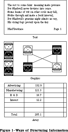 Figure 1–Ways of Structuring Information
Arrays are one- or two-dimensional arrangements of fields. If the array is one-dimensional, it's called a form; if it's two-dimensional it's called a table. Each field, in turn, contains a collection of information, usually text, but conceivably graphics. A table can be readily identified on the screen, since it consists of rows and columns of fields (often called cells), separated by horizontal and vertical lines. A form is something you fill out, like a credit-card application. The fields in a form can be arranged in any appropriate way; nevertheless, the application regards the fields as in a definite linear order.
Each of these three ways of presenting information retains its integrity, regardless of the context in which it appears. For example, a field in an array can contain text. When the user is manipulating the field as a whole, the field is treated as part of the array. When the user wants to change the contents of the field, the contents are edited in the same way as any other text.
_______________________________________________________________________________
»USING GRAPHICS
_______________________________________________________________________________
A key feature of the Macintosh is its high-resolution graphics screen. To use this screen to its best advantage, Macintosh applications use graphics copiously, even in places where other applications use text. As much as possible, all commands, features, and parameters of an application, and all the user's data, appear as graphic objects on the screen. Figure 2 shows some of the ways that applications can use graphics to communicate with the user.
Figure 1–Ways of Structuring Information
Arrays are one- or two-dimensional arrangements of fields. If the array is one-dimensional, it's called a form; if it's two-dimensional it's called a table. Each field, in turn, contains a collection of information, usually text, but conceivably graphics. A table can be readily identified on the screen, since it consists of rows and columns of fields (often called cells), separated by horizontal and vertical lines. A form is something you fill out, like a credit-card application. The fields in a form can be arranged in any appropriate way; nevertheless, the application regards the fields as in a definite linear order.
Each of these three ways of presenting information retains its integrity, regardless of the context in which it appears. For example, a field in an array can contain text. When the user is manipulating the field as a whole, the field is treated as part of the array. When the user wants to change the contents of the field, the contents are edited in the same way as any other text.
_______________________________________________________________________________
»USING GRAPHICS
_______________________________________________________________________________
A key feature of the Macintosh is its high-resolution graphics screen. To use this screen to its best advantage, Macintosh applications use graphics copiously, even in places where other applications use text. As much as possible, all commands, features, and parameters of an application, and all the user's data, appear as graphic objects on the screen. Figure 2 shows some of the ways that applications can use graphics to communicate with the user.
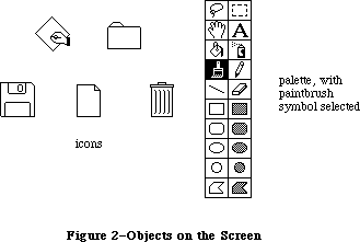 Figure 2–Objects on the Screen
Objects, whenever applicable, resemble the familiar material objects whose functions they emulate. Objects that act like pushbuttons "light up" when pressed; the Trash icon looks like a trash can.
Objects are designed to look good on the screen. Predefined graphics patterns can give objects a shape and texture beyond simple line graphics. Placing a drop-shadow slightly below and to the right of an object can give it a three-dimensional appearance.
Generally, when the user clicks on an object, it's highlighted to distinguish it from its peers. The most common way to show this highlighting is by inverting the object: changing black to white and vice versa. In some situations, other forms of highlighting may be more appropriate. The important thing is that there should always be some sort of feedback, so that the user knows that the click had an effect.
One special aspect of the appearance of a document on the screen is visual fidelity. This principle is also known as "what you see is what you get". It primarily refers to printing: The version of a document shown on the screen should be as close as possible to its printed version, taking into account inevitable differences due to different media.
_______________________________________________________________________________
»Icons
A fundamental object in Macintosh software is the icon, a small graphic object that's usually symbolic of an operation or of a larger entity such as a document.
Icons can contribute greatly to the clarity and attractiveness of an application. The use of icons also makes it much easier to translate programs into other languages. Wherever an explanation or label is needed, consider using an icon instead of text.
_______________________________________________________________________________
»Palettes
Some applications use palettes as a quick way for the user to change from one operation to another. A palette is a collection of small symbols, usually enclosed in rectangles. A symbol can be an icon, a pattern, a character, or just a drawing, that stands for an operation. When the user clicks on one of the symbols (or in its rectangle), it's distinguished from the other symbols, such as by highlighting, and the previous symbol goes back to its normal state.
Typically, the symbol that's selected determines what operations the user can perform. Selecting a palette symbol puts the user into a mode. This use of modes can be justified because changing from one mode to another is almost instantaneous, and the user can always see at a glance which mode is in effect. Like all modal features, palettes should be used only when they're the most natural way to structure an application.
A palette can either be part of a window (as in MacDraw™), or a separate window (as in MacPaint). Each system has its disadvantages. If the palette is part of the window, then parts of the palette might be concealed if the user makes the window smaller. On the other hand, if it's not part of the window, then it takes up extra space on the desktop. If an application supports multiple documents open at the same time, it might be better to put a separate palette in each window, so that a different palette symbol can be in effect in each document.
_______________________________________________________________________________
»COMPONENTS OF THE MACINTOSH SYSTEM
_______________________________________________________________________________
This section explains the relationship among the principal large-scale components of the Macintosh system (from an external point of view).
The main vehicle for the interaction of the user and the system is the application. Only one application is active at a time. When an application is active, it's in control of all communications between the user and the system. The application's menus are in the menu bar, and the application is in charge of all windows as well as the desktop.
To the user, the main unit of information is the document. Each document is a unified collection of information—a single business letter or spreadsheet or chart. A complex application, such as a data base, might require several related documents. Some documents can be processed by more than one application, but each document has a principal application, which is usually the one that created it. The other applications that process the document are called secondary applications.
The only way the user can actually see the document (except by printing it) is through a window. The application puts one or more windows on the screen; each window shows a view of a document or of auxiliary information used in processing the document. The part of the screen underlying all the windows is called the desktop.
The user returns to the Finder to change applications. When the Finder is active, if the user opens either an application a document belonging to an application, the application becomes active and displays the document window.
Internally, applications and documents are both kept in files. However, the user never sees files as such, so they don't really enter into the user interface.
_______________________________________________________________________________
»THE KEYBOARD
_______________________________________________________________________________
The Macintosh keyboard is used primarily for entering text. Since commands are chosen from menus or by clicking somewhere on the screen, the keyboard isn't needed for this function, although it can be used for alternative ways to enter commands.
The keys on the keyboard are arranged in familiar typewriter fashion. The U.S. keyboard on the Macintosh 128K and 512K is shown in Figure 3. The Macintosh XL keyboard looks the same except that the key to the left of the space bar is labeled with an apple symbol.
Figure 2–Objects on the Screen
Objects, whenever applicable, resemble the familiar material objects whose functions they emulate. Objects that act like pushbuttons "light up" when pressed; the Trash icon looks like a trash can.
Objects are designed to look good on the screen. Predefined graphics patterns can give objects a shape and texture beyond simple line graphics. Placing a drop-shadow slightly below and to the right of an object can give it a three-dimensional appearance.
Generally, when the user clicks on an object, it's highlighted to distinguish it from its peers. The most common way to show this highlighting is by inverting the object: changing black to white and vice versa. In some situations, other forms of highlighting may be more appropriate. The important thing is that there should always be some sort of feedback, so that the user knows that the click had an effect.
One special aspect of the appearance of a document on the screen is visual fidelity. This principle is also known as "what you see is what you get". It primarily refers to printing: The version of a document shown on the screen should be as close as possible to its printed version, taking into account inevitable differences due to different media.
_______________________________________________________________________________
»Icons
A fundamental object in Macintosh software is the icon, a small graphic object that's usually symbolic of an operation or of a larger entity such as a document.
Icons can contribute greatly to the clarity and attractiveness of an application. The use of icons also makes it much easier to translate programs into other languages. Wherever an explanation or label is needed, consider using an icon instead of text.
_______________________________________________________________________________
»Palettes
Some applications use palettes as a quick way for the user to change from one operation to another. A palette is a collection of small symbols, usually enclosed in rectangles. A symbol can be an icon, a pattern, a character, or just a drawing, that stands for an operation. When the user clicks on one of the symbols (or in its rectangle), it's distinguished from the other symbols, such as by highlighting, and the previous symbol goes back to its normal state.
Typically, the symbol that's selected determines what operations the user can perform. Selecting a palette symbol puts the user into a mode. This use of modes can be justified because changing from one mode to another is almost instantaneous, and the user can always see at a glance which mode is in effect. Like all modal features, palettes should be used only when they're the most natural way to structure an application.
A palette can either be part of a window (as in MacDraw™), or a separate window (as in MacPaint). Each system has its disadvantages. If the palette is part of the window, then parts of the palette might be concealed if the user makes the window smaller. On the other hand, if it's not part of the window, then it takes up extra space on the desktop. If an application supports multiple documents open at the same time, it might be better to put a separate palette in each window, so that a different palette symbol can be in effect in each document.
_______________________________________________________________________________
»COMPONENTS OF THE MACINTOSH SYSTEM
_______________________________________________________________________________
This section explains the relationship among the principal large-scale components of the Macintosh system (from an external point of view).
The main vehicle for the interaction of the user and the system is the application. Only one application is active at a time. When an application is active, it's in control of all communications between the user and the system. The application's menus are in the menu bar, and the application is in charge of all windows as well as the desktop.
To the user, the main unit of information is the document. Each document is a unified collection of information—a single business letter or spreadsheet or chart. A complex application, such as a data base, might require several related documents. Some documents can be processed by more than one application, but each document has a principal application, which is usually the one that created it. The other applications that process the document are called secondary applications.
The only way the user can actually see the document (except by printing it) is through a window. The application puts one or more windows on the screen; each window shows a view of a document or of auxiliary information used in processing the document. The part of the screen underlying all the windows is called the desktop.
The user returns to the Finder to change applications. When the Finder is active, if the user opens either an application a document belonging to an application, the application becomes active and displays the document window.
Internally, applications and documents are both kept in files. However, the user never sees files as such, so they don't really enter into the user interface.
_______________________________________________________________________________
»THE KEYBOARD
_______________________________________________________________________________
The Macintosh keyboard is used primarily for entering text. Since commands are chosen from menus or by clicking somewhere on the screen, the keyboard isn't needed for this function, although it can be used for alternative ways to enter commands.
The keys on the keyboard are arranged in familiar typewriter fashion. The U.S. keyboard on the Macintosh 128K and 512K is shown in Figure 3. The Macintosh XL keyboard looks the same except that the key to the left of the space bar is labeled with an apple symbol.
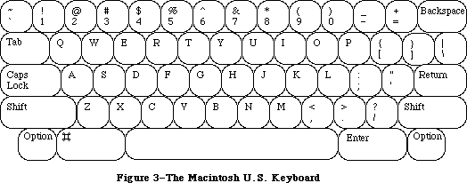 Figure 3–The Macintosh U.S. Keyboard
The standard keyboard for the Macintosh SE and Macintosh II includes a Control key and an Escape key. The optional extended keyboard has in addition 6 dedicated function keys, 15 function keys that are user-definable, and 3 LED indicators for key lock conditions. The Apple Extended Keyboard is shown in Figure 4.
Figure 3–The Macintosh U.S. Keyboard
The standard keyboard for the Macintosh SE and Macintosh II includes a Control key and an Escape key. The optional extended keyboard has in addition 6 dedicated function keys, 15 function keys that are user-definable, and 3 LED indicators for key lock conditions. The Apple Extended Keyboard is shown in Figure 4.
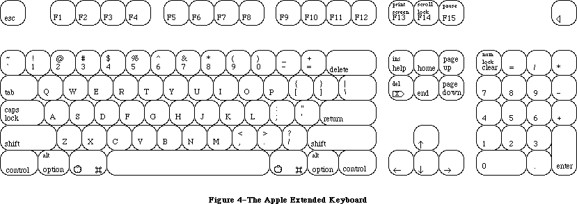 Figure 4–The Apple Extended Keyboard
There are two kinds of keys: character keys and modifier keys. A character key sends characters to the computer; a modifier key alters the meaning of a character key if it's held down while the character key is pressed.
_______________________________________________________________________________
»Character Keys
Character keys include keys for letters, numbers, and symbols, as well as the space bar. If the user presses one of these keys while entering text, the corresponding character is added to the text. Other keys, such as the Enter, Tab, Return, Backspace, and Clear keys, are also considered character keys. However, the result of pressing one of these keys depends on the application and the context.
The Enter key tells the application that the user is through entering information in a particular area of the document, such as a field in an array. Most applications add information to a document as soon as the user types or draws it. However, the application may need to wait until a whole collection of information is available before processing it. In this case, the user presses the Enter key to signal that the information is complete.
The Tab key is a signal to proceed: It signals movement to the next item in a sequence. Tab often implies an Enter operation before the Tab motion is performed.
The Return key is another signal to proceed, but it defines a different type of motion than Tab. A press of the Return key signals movement to the leftmost field one step down (just like a carriage return on a typewriter). Return can also imply an Enter operation before the Return operation.
Note: Return and Enter also dismiss dialog and alert boxes
(see "Dialogs and Alerts").
During entry of text into a document, Tab moves to the next tab stop, Return moves to the beginning of the next line, and Enter is ignored.
Backspace is used to delete text or graphics. The exact use of Backspace in text is described in the "Text Editing" section.
The Clear key on the numeric keypad has the same effect as the Clear command in the Edit menu; that is, it removes the selection from the document without putting it in the Clipboard. This is also explained in the "Text Editing" section. Because the keypad is optional equipment on the Macintosh 128K and 512K, no application should ever require use of the Clear key or any other key on the pad.
_______________________________________________________________________________
»Modifier Keys: Shift, Caps Lock, Option, and Command
There are six keys on the keyboard that change the interpretation of keystrokes: two Shift keys, two Option keys, one Caps Lock key, and one Command key (the key to the left of the space bar). These keys change the interpretation of keystrokes, and sometimes mouse actions. When one of these keys is held down, the effect of the other keys (or the mouse button) may change.
The Shift and Option keys choose among the characters on each character key. Shift gives the upper character on two-character keys, or the uppercase letter on alphabetic keys. The Shift key is also used in conjunction with the mouse for extending a selection; see "Selecting". Option gives an alternate character set interpretation, including international characters, special symbols, and so on. Shift and Option can be used in combination.
Caps Lock latches in the down position when pressed, and releases when pressed again. When down it gives the uppercase letter on alphabetic keys. The operation of Caps Lock on alphabetic keys is parallel to that of the Shift key, but the Caps Lock key has no effect whatsoever on any of the other keys. Caps Lock and Option can be used in combination on alphabetic keys.
Pressing a character key while holding down the Command key usually tells the application to interpret the key as a command, not as a character (see
"Commands").
_______________________________________________________________________________
»Control and Escape Keys
The Control and Esc (Escape) keys should be used for their standard meanings; neither should be used as an additional command-key modifier. Since not all keyboards may have a Control or Esc key, neither should be depended upon.
The main use of the Control key is to generate control characters for terminal emulation programs. (The Command key is used for this purpose on terminals lacking a Control key.) A secondary use that also derives from past practice is calling user-defined functions, or macros. The varying placement of the Control key on different keyboards means that it should not be used for routine entry, as touch-typists may find its position inconvenient.
The Esc key has the general meaning “let me out of here”. In certain contexts its meaning is specific:
• The user can press Esc as a quick way to indicate Cancel in a dialog box.
• The user can press Esc to stop an operation in progress, such as printing.
(Using Esc this way is like pressing Command-period.)
• If an application absolutely requires a series of dialog boxes (a fresh
look at program design usually eliminates such sequences), the user
should be able to use Esc to move backward through the boxes.
Pressing Esc should never cause the user to back out of an operation that would require extensive time or work to reenter, and it should never cause the user to lose valuable information. When the user presses Esc during a lengthy operation, the application should display a confirmation dialog box to be sure Esc wasn’t pressed accidentally.
_______________________________________________________________________________
»Function Keys
There are two types of function keys: dedicated and user-definable. The user-definable keys—labeled F1 through F15—are not to be defined by an application. F1 through F4 represent Undo, Cut, Copy, and Paste, respectively, in any applications that use these commands.
The six dedicated function keys are labeled Help, Del, Home, End, Page Up, and Page Down. These keys are used as follows:
• Help: Pressing the Help key should produce help (it’s equivalent to
pressing Command-?). The sort of help available varies between
applications; if a full, contextual help system is not available,
some sort of useful help screen should be provided.
• Fwd Del: Pressing Fwd Del performs a forward delete: the character
directly to the right of the insertion point is removed, pulling
everything to the right of the removed character toward the insertion
point. The effect is that the insertion point remains stable while
it “vacuums” everything ahead of it.
If Fwd Del is pressed when there is a current selection, it has the
same effect as pressing Delete (Backspace) or choosing Clear from the
Edit menu.
• Home: Pressing the Home key is equivalent to moving the scroll boxes
(elevators) all the way to the top of the vertical scroll bar and to
the left end of the horizontal scroll bar.
• End: The flip-side of Home: it’s equivalent to moving the scroll boxes
(elevators) all the way to the bottom of the vertical scroll bar and to
the right end of the horizontal scroll bar.
• Page Up: Equivalent to clicking the mouse pointer in the upper gray
region of the vertical scroll bar.
• Page Down: Equivalent to clicking the mouse pointer in the lower gray
region of the vertical scroll bar.
Notice that the Home, End, Page Up, and Page Down keys have no effect on the insertion point or on any selected material. These keys change the screen display only, for three reasons:
• The analogy to scrolling means that the keys behave as users expect.
• Users can easily change the insertion point by clicking in the
jumped-to window.
• Window-by-window jumping with a moving insertion point can be done by
Command–arrow key combinations, as described in the “Arrow Keys” section.
Because the keys are visual only, the Page Up and Page Down keys jump relative to the visible window, not relative to the insertion point.
_______________________________________________________________________________
»Typeahead and Auto-Repeat
If the user types when the Macintosh is unable to process the keystrokes immediately, or types more quickly than the Macintosh can handle, the extra keystrokes are queued, to be processed later. This queuing is called typeahead. There's a limit to the number of keystrokes that can be queued, but the limit is usually not a problem unless the user types while the application is performing a lengthy operation.
When a character is held down for a certain amount of time, it starts repeating automatically. The user can set the delay and the rate of repetition with the Control Panel desk accessory. An application can tell whether a series of n keystrokes was generated by auto-repeat or by pressing the same key n times. It can choose to disregard keystrokes generated by auto-repeat; this is usually a good idea for menu commands chosen with the Command key.
Holding down a modifier key has the same effect as pressing it once. However, if the user holds down a modifier key and a character key at the same time, the effect is the same as if the user held down the modifier key while pressing the character key repeatedly.
Auto-repeat does not function during typeahead; it operates only when the application is ready to accept keyboard input.
_______________________________________________________________________________
»Versions of the Keyboard
There are two physical versions of the keyboard: U.S. and international. The international version has one more key than the U.S. version. The standard layout on the international version is designed to conform to the International Standards Organization (ISO) standard; the U.S. key layout mimics that of common American office typewriters. International keyboards have different labels on the keys in different countries, but the overall layout is the same.
Note: An illustration of the international keyboard (with Great Britain
key caps) is given in the Toolbox Event Manager chapter.
_______________________________________________________________________________
»The Numeric Keypad
An optional numeric keypad can be hooked up between the main unit and the standard keyboard on a Macintosh 128K or 512K; on the Macintosh XL, the numeric keypad is built in, next to the keyboard. Figure 5 shows the U.S. keypad. In other countries, the keys may have different labels.
Figure 4–The Apple Extended Keyboard
There are two kinds of keys: character keys and modifier keys. A character key sends characters to the computer; a modifier key alters the meaning of a character key if it's held down while the character key is pressed.
_______________________________________________________________________________
»Character Keys
Character keys include keys for letters, numbers, and symbols, as well as the space bar. If the user presses one of these keys while entering text, the corresponding character is added to the text. Other keys, such as the Enter, Tab, Return, Backspace, and Clear keys, are also considered character keys. However, the result of pressing one of these keys depends on the application and the context.
The Enter key tells the application that the user is through entering information in a particular area of the document, such as a field in an array. Most applications add information to a document as soon as the user types or draws it. However, the application may need to wait until a whole collection of information is available before processing it. In this case, the user presses the Enter key to signal that the information is complete.
The Tab key is a signal to proceed: It signals movement to the next item in a sequence. Tab often implies an Enter operation before the Tab motion is performed.
The Return key is another signal to proceed, but it defines a different type of motion than Tab. A press of the Return key signals movement to the leftmost field one step down (just like a carriage return on a typewriter). Return can also imply an Enter operation before the Return operation.
Note: Return and Enter also dismiss dialog and alert boxes
(see "Dialogs and Alerts").
During entry of text into a document, Tab moves to the next tab stop, Return moves to the beginning of the next line, and Enter is ignored.
Backspace is used to delete text or graphics. The exact use of Backspace in text is described in the "Text Editing" section.
The Clear key on the numeric keypad has the same effect as the Clear command in the Edit menu; that is, it removes the selection from the document without putting it in the Clipboard. This is also explained in the "Text Editing" section. Because the keypad is optional equipment on the Macintosh 128K and 512K, no application should ever require use of the Clear key or any other key on the pad.
_______________________________________________________________________________
»Modifier Keys: Shift, Caps Lock, Option, and Command
There are six keys on the keyboard that change the interpretation of keystrokes: two Shift keys, two Option keys, one Caps Lock key, and one Command key (the key to the left of the space bar). These keys change the interpretation of keystrokes, and sometimes mouse actions. When one of these keys is held down, the effect of the other keys (or the mouse button) may change.
The Shift and Option keys choose among the characters on each character key. Shift gives the upper character on two-character keys, or the uppercase letter on alphabetic keys. The Shift key is also used in conjunction with the mouse for extending a selection; see "Selecting". Option gives an alternate character set interpretation, including international characters, special symbols, and so on. Shift and Option can be used in combination.
Caps Lock latches in the down position when pressed, and releases when pressed again. When down it gives the uppercase letter on alphabetic keys. The operation of Caps Lock on alphabetic keys is parallel to that of the Shift key, but the Caps Lock key has no effect whatsoever on any of the other keys. Caps Lock and Option can be used in combination on alphabetic keys.
Pressing a character key while holding down the Command key usually tells the application to interpret the key as a command, not as a character (see
"Commands").
_______________________________________________________________________________
»Control and Escape Keys
The Control and Esc (Escape) keys should be used for their standard meanings; neither should be used as an additional command-key modifier. Since not all keyboards may have a Control or Esc key, neither should be depended upon.
The main use of the Control key is to generate control characters for terminal emulation programs. (The Command key is used for this purpose on terminals lacking a Control key.) A secondary use that also derives from past practice is calling user-defined functions, or macros. The varying placement of the Control key on different keyboards means that it should not be used for routine entry, as touch-typists may find its position inconvenient.
The Esc key has the general meaning “let me out of here”. In certain contexts its meaning is specific:
• The user can press Esc as a quick way to indicate Cancel in a dialog box.
• The user can press Esc to stop an operation in progress, such as printing.
(Using Esc this way is like pressing Command-period.)
• If an application absolutely requires a series of dialog boxes (a fresh
look at program design usually eliminates such sequences), the user
should be able to use Esc to move backward through the boxes.
Pressing Esc should never cause the user to back out of an operation that would require extensive time or work to reenter, and it should never cause the user to lose valuable information. When the user presses Esc during a lengthy operation, the application should display a confirmation dialog box to be sure Esc wasn’t pressed accidentally.
_______________________________________________________________________________
»Function Keys
There are two types of function keys: dedicated and user-definable. The user-definable keys—labeled F1 through F15—are not to be defined by an application. F1 through F4 represent Undo, Cut, Copy, and Paste, respectively, in any applications that use these commands.
The six dedicated function keys are labeled Help, Del, Home, End, Page Up, and Page Down. These keys are used as follows:
• Help: Pressing the Help key should produce help (it’s equivalent to
pressing Command-?). The sort of help available varies between
applications; if a full, contextual help system is not available,
some sort of useful help screen should be provided.
• Fwd Del: Pressing Fwd Del performs a forward delete: the character
directly to the right of the insertion point is removed, pulling
everything to the right of the removed character toward the insertion
point. The effect is that the insertion point remains stable while
it “vacuums” everything ahead of it.
If Fwd Del is pressed when there is a current selection, it has the
same effect as pressing Delete (Backspace) or choosing Clear from the
Edit menu.
• Home: Pressing the Home key is equivalent to moving the scroll boxes
(elevators) all the way to the top of the vertical scroll bar and to
the left end of the horizontal scroll bar.
• End: The flip-side of Home: it’s equivalent to moving the scroll boxes
(elevators) all the way to the bottom of the vertical scroll bar and to
the right end of the horizontal scroll bar.
• Page Up: Equivalent to clicking the mouse pointer in the upper gray
region of the vertical scroll bar.
• Page Down: Equivalent to clicking the mouse pointer in the lower gray
region of the vertical scroll bar.
Notice that the Home, End, Page Up, and Page Down keys have no effect on the insertion point or on any selected material. These keys change the screen display only, for three reasons:
• The analogy to scrolling means that the keys behave as users expect.
• Users can easily change the insertion point by clicking in the
jumped-to window.
• Window-by-window jumping with a moving insertion point can be done by
Command–arrow key combinations, as described in the “Arrow Keys” section.
Because the keys are visual only, the Page Up and Page Down keys jump relative to the visible window, not relative to the insertion point.
_______________________________________________________________________________
»Typeahead and Auto-Repeat
If the user types when the Macintosh is unable to process the keystrokes immediately, or types more quickly than the Macintosh can handle, the extra keystrokes are queued, to be processed later. This queuing is called typeahead. There's a limit to the number of keystrokes that can be queued, but the limit is usually not a problem unless the user types while the application is performing a lengthy operation.
When a character is held down for a certain amount of time, it starts repeating automatically. The user can set the delay and the rate of repetition with the Control Panel desk accessory. An application can tell whether a series of n keystrokes was generated by auto-repeat or by pressing the same key n times. It can choose to disregard keystrokes generated by auto-repeat; this is usually a good idea for menu commands chosen with the Command key.
Holding down a modifier key has the same effect as pressing it once. However, if the user holds down a modifier key and a character key at the same time, the effect is the same as if the user held down the modifier key while pressing the character key repeatedly.
Auto-repeat does not function during typeahead; it operates only when the application is ready to accept keyboard input.
_______________________________________________________________________________
»Versions of the Keyboard
There are two physical versions of the keyboard: U.S. and international. The international version has one more key than the U.S. version. The standard layout on the international version is designed to conform to the International Standards Organization (ISO) standard; the U.S. key layout mimics that of common American office typewriters. International keyboards have different labels on the keys in different countries, but the overall layout is the same.
Note: An illustration of the international keyboard (with Great Britain
key caps) is given in the Toolbox Event Manager chapter.
_______________________________________________________________________________
»The Numeric Keypad
An optional numeric keypad can be hooked up between the main unit and the standard keyboard on a Macintosh 128K or 512K; on the Macintosh XL, the numeric keypad is built in, next to the keyboard. Figure 5 shows the U.S. keypad. In other countries, the keys may have different labels.
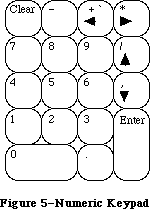 Figure 5–Numeric Keypad
The keypad contains 18 keys, some of which duplicate keys on the main keyboard, and some of which are unique to the keypad. The application can tell whether the keystrokes have come from the main keyboard or the numeric keypad. The keys on the keypad follow the same rules for typeahead and auto-repeat as the keyboard.
Four keys on the keypad are labeled with “field-motion” symbols: small rectangles with arrows pointing in various directions. Some applications may use these keys to select objects in the direction indicated by the key; the most likely use for this feature is in tables. To obtain the characters
(+ * / ,) available on these keys, the user must also hold down the Shift key on the keyboard.
Since the numeric keypad is optional equipment on the Macintosh 128K and 512K, no application should require it or any keys available on it in order to perform standard functions. Specifically, since the Clear key isn’t available on the main keyboard, a Clear function may be implemented with this key only as the equivalent of the Clear command in the Edit menu.
_______________________________________________________________________________
»ARROW KEYS
_______________________________________________________________________________
The Macintosh Plus keyboard includes four arrow keys: Up Arrow, Down Arrow, Left Arrow, and Right Arrow.
Figure 5–Numeric Keypad
The keypad contains 18 keys, some of which duplicate keys on the main keyboard, and some of which are unique to the keypad. The application can tell whether the keystrokes have come from the main keyboard or the numeric keypad. The keys on the keypad follow the same rules for typeahead and auto-repeat as the keyboard.
Four keys on the keypad are labeled with “field-motion” symbols: small rectangles with arrows pointing in various directions. Some applications may use these keys to select objects in the direction indicated by the key; the most likely use for this feature is in tables. To obtain the characters
(+ * / ,) available on these keys, the user must also hold down the Shift key on the keyboard.
Since the numeric keypad is optional equipment on the Macintosh 128K and 512K, no application should require it or any keys available on it in order to perform standard functions. Specifically, since the Clear key isn’t available on the main keyboard, a Clear function may be implemented with this key only as the equivalent of the Clear command in the Edit menu.
_______________________________________________________________________________
»ARROW KEYS
_______________________________________________________________________________
The Macintosh Plus keyboard includes four arrow keys: Up Arrow, Down Arrow, Left Arrow, and Right Arrow.
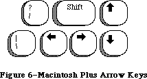 Figure 6–Macintosh Plus Arrow Keys
_______________________________________________________________________________
»Appropriate Uses for the Arrow Keys
The arrow keys do not replace the mouse. They can be used in addition to the mouse as a shortcut for moving the insertion point and (under some circumstances) for making selections. The following rules are the minimum guidelines for the use of arrow keys, leaving application programmers relatively free to expand on them where things are left undefined. Extensions necessary for a particular application should be done in the spirit of the Macintosh user interface.
It’s up to you to decide whether it’s worth the effort to create arrow key shortcuts for mouse functions. Many users find that remembering a key combination on the order of Command–Shift–Left Arrow is more trouble than it’s worth and would rather use a mouse anyway. In other situations, it’s more convenient to use the keyboard. Some people have difficulty using a mouse and appreciate being able to use the keyboard instead.
You should make use of the arrow keys only where it’s appropriate to the application. Applications that deal with text or arrays (word processors, spreadsheets, and data bases, for example) have an insertion point. This insertion point can always be moved by the mouse and, with the new keyboard, with the arrow keys as well.
As a general rule, arrow keys are used to move the insertion point and to expand or shrink selections. Arrow keys are never used to duplicate the function of the scroll bars or to move the pointer. In a graphics application, the arrow keys should not be used to move a selected object.
_______________________________________________________________________________
»Moving the Insertion Point With Arrow Keys
The Left Arrow and Right Arrow keys move the insertion point one character left and right, respectively.
Up Arrow and Down Arrow move the insertion point up and down one line, respectively. The horizontal screen position should be maintained in terms of screen pixels but not necessarily in terms of characters, because the insertion point moves to the nearest character boundary on the new line. (Character boundaries seldom line up vertically when proportional fonts are used.) During successive movements up or down, you should keep track of the original horizontal screen position; otherwise, accumulated round-off errors might cause the insertion point to move a significant distance from the original horizontal position as it moves from line to line.
»Moving the Insertion Point in Empty Documents
Various text-editing programs treat empty documents in different ways. Some assume that an empty document contains no characters, in which case clicking at the bottom of a blank screen causes the insertion point to appear at the top. In this situation, Down Arrow cannot move the insertion point into the blank space (because there are no characters there).
Other applications treat an empty document as a page of space characters, in which case clicking at the bottom of a blank screen puts the insertion point where the user clicked and lets the user type characters there, overwriting the spaces. Down Arrow moves the insertion point straight down through the spaces.
Whichever paradigm you choose for your application, be consistent.
»Modifier Keys With Arrow Keys
Holding down the Command key while pressing an arrow key should move the insertion point to the appropriate edge of the window. If the insertion point is already at the edge of the window, the document should be scrolled one windowful in the appropriate direction and the insertion point should move to the same edge of the new windowful. Command–Up Arrow moves to the top of the window, Command–Down Arrow to the bottom, Command–Left Arrow to the left edge, and Command–Right Arrow to the right edge.
The Option key is reserved as a “semantic modifier” key. The application determines what the semantic units are. For example, in a word processor, where the basic semantic unit is the character and the next larger unit is the word, Option–Left Arrow and Option–Right Arrow might move the insertion point to the beginning and end, respectively, of a word. (Movement of the insertion point by word boundaries should use the same definition of “word” that the application uses for double clicking.) The next larger semantic unit could be defined as the sentence, in which case Option–Left Arrow and Option–Right Arrow would move the insertion point to the beginning or end of a sentence. In a programming language editor, where the basic semantic unit is the token and the next larger one might be the line, Option–Left Arrow and Option–Right Arrow might move the insertion point left and right to the beginning and end of the line, respectively.
In an application (such as a spreadsheet) that represents itself as an array, the basic semantic unit would be the cell. Option–Left Arrow would designate the cell to the left of the currently active cell as the new active cell, and so on. Using modifier keys with arrow keys doesn’t do anything to the data; Option–Left Arrow just moves the selection to the next cell to the left.
Though the use of multiple modifier key combinations (such as Command–Option–Left Arrow) is discouraged, it’s fine to use the Shift key with any one of the other modifier keys for making a selection (see “Making a Selection With Arrow Keys” below). Keep in mind that if multiple keys must be pressed simultaneously, they should be fairly close together—otherwise many people won’t be able to use that combination.
_______________________________________________________________________________
»Making a Selection With Arrow Keys
To use arrow keys to make a selection, the user holds down Shift while pressing an arrow key. Application programs that depend (as TextEdit does) on the numeric keypad should not use these Shift–arrow key combinations because the ASCII codes for the four Shift–arrow key combinations are the same as those for the keypad’s +, *, /, and = keys. If the use of Shift–arrow for making selections is more important to your application than the numeric keypad, the following paragraphs describe how it should work.
After a Shift–arrow key combination has been pressed, the insertion point moves and the range over which it moves becomes selected. If both the Shift key and another modifier key are held down, the insertion point moves (as defined for the particular modifier key) and the range over which the insertion point moves becomes selected. For example, Shift–Left Arrow selects the character to the left of the insertion point, Command–Shift–Left Arrow selects from the insertion point to the left edge of the window, and Option–Shift–Left Arrow selects the whole word that contains the character to the left of the insertion point (just like double clicking on a word).
A selection made using the mouse is no different from one made using arrow keys. A selection started with the mouse can be extended using Shift and Left Arrow or Right Arrow.
The two ends of a selected range have different characteristics and different names. The place where the insertion point was when selection was started is called the anchor point. The place to which the insertion point moves to complete the selection is called the active end. Once selection begins, the anchor point cannot be moved except by beginning a new selection. To extend or shrink a selection, the user moves the active end as specified here. As the active end moves, it can cross over the anchor point.
In a text application, pressing Shift and either Left Arrow or Right Arrow selects a single character. Assuming that Left Arrow key was used, the anchor point of the selection is on the right side of the selection, the active end on the left. Each subsequent Shift–Left Arrow adds another character to the left side of the selection. A Shift–Right Arrow at this point shrinks the selection. Figure 7 summarizes these actions.
Figure 6–Macintosh Plus Arrow Keys
_______________________________________________________________________________
»Appropriate Uses for the Arrow Keys
The arrow keys do not replace the mouse. They can be used in addition to the mouse as a shortcut for moving the insertion point and (under some circumstances) for making selections. The following rules are the minimum guidelines for the use of arrow keys, leaving application programmers relatively free to expand on them where things are left undefined. Extensions necessary for a particular application should be done in the spirit of the Macintosh user interface.
It’s up to you to decide whether it’s worth the effort to create arrow key shortcuts for mouse functions. Many users find that remembering a key combination on the order of Command–Shift–Left Arrow is more trouble than it’s worth and would rather use a mouse anyway. In other situations, it’s more convenient to use the keyboard. Some people have difficulty using a mouse and appreciate being able to use the keyboard instead.
You should make use of the arrow keys only where it’s appropriate to the application. Applications that deal with text or arrays (word processors, spreadsheets, and data bases, for example) have an insertion point. This insertion point can always be moved by the mouse and, with the new keyboard, with the arrow keys as well.
As a general rule, arrow keys are used to move the insertion point and to expand or shrink selections. Arrow keys are never used to duplicate the function of the scroll bars or to move the pointer. In a graphics application, the arrow keys should not be used to move a selected object.
_______________________________________________________________________________
»Moving the Insertion Point With Arrow Keys
The Left Arrow and Right Arrow keys move the insertion point one character left and right, respectively.
Up Arrow and Down Arrow move the insertion point up and down one line, respectively. The horizontal screen position should be maintained in terms of screen pixels but not necessarily in terms of characters, because the insertion point moves to the nearest character boundary on the new line. (Character boundaries seldom line up vertically when proportional fonts are used.) During successive movements up or down, you should keep track of the original horizontal screen position; otherwise, accumulated round-off errors might cause the insertion point to move a significant distance from the original horizontal position as it moves from line to line.
»Moving the Insertion Point in Empty Documents
Various text-editing programs treat empty documents in different ways. Some assume that an empty document contains no characters, in which case clicking at the bottom of a blank screen causes the insertion point to appear at the top. In this situation, Down Arrow cannot move the insertion point into the blank space (because there are no characters there).
Other applications treat an empty document as a page of space characters, in which case clicking at the bottom of a blank screen puts the insertion point where the user clicked and lets the user type characters there, overwriting the spaces. Down Arrow moves the insertion point straight down through the spaces.
Whichever paradigm you choose for your application, be consistent.
»Modifier Keys With Arrow Keys
Holding down the Command key while pressing an arrow key should move the insertion point to the appropriate edge of the window. If the insertion point is already at the edge of the window, the document should be scrolled one windowful in the appropriate direction and the insertion point should move to the same edge of the new windowful. Command–Up Arrow moves to the top of the window, Command–Down Arrow to the bottom, Command–Left Arrow to the left edge, and Command–Right Arrow to the right edge.
The Option key is reserved as a “semantic modifier” key. The application determines what the semantic units are. For example, in a word processor, where the basic semantic unit is the character and the next larger unit is the word, Option–Left Arrow and Option–Right Arrow might move the insertion point to the beginning and end, respectively, of a word. (Movement of the insertion point by word boundaries should use the same definition of “word” that the application uses for double clicking.) The next larger semantic unit could be defined as the sentence, in which case Option–Left Arrow and Option–Right Arrow would move the insertion point to the beginning or end of a sentence. In a programming language editor, where the basic semantic unit is the token and the next larger one might be the line, Option–Left Arrow and Option–Right Arrow might move the insertion point left and right to the beginning and end of the line, respectively.
In an application (such as a spreadsheet) that represents itself as an array, the basic semantic unit would be the cell. Option–Left Arrow would designate the cell to the left of the currently active cell as the new active cell, and so on. Using modifier keys with arrow keys doesn’t do anything to the data; Option–Left Arrow just moves the selection to the next cell to the left.
Though the use of multiple modifier key combinations (such as Command–Option–Left Arrow) is discouraged, it’s fine to use the Shift key with any one of the other modifier keys for making a selection (see “Making a Selection With Arrow Keys” below). Keep in mind that if multiple keys must be pressed simultaneously, they should be fairly close together—otherwise many people won’t be able to use that combination.
_______________________________________________________________________________
»Making a Selection With Arrow Keys
To use arrow keys to make a selection, the user holds down Shift while pressing an arrow key. Application programs that depend (as TextEdit does) on the numeric keypad should not use these Shift–arrow key combinations because the ASCII codes for the four Shift–arrow key combinations are the same as those for the keypad’s +, *, /, and = keys. If the use of Shift–arrow for making selections is more important to your application than the numeric keypad, the following paragraphs describe how it should work.
After a Shift–arrow key combination has been pressed, the insertion point moves and the range over which it moves becomes selected. If both the Shift key and another modifier key are held down, the insertion point moves (as defined for the particular modifier key) and the range over which the insertion point moves becomes selected. For example, Shift–Left Arrow selects the character to the left of the insertion point, Command–Shift–Left Arrow selects from the insertion point to the left edge of the window, and Option–Shift–Left Arrow selects the whole word that contains the character to the left of the insertion point (just like double clicking on a word).
A selection made using the mouse is no different from one made using arrow keys. A selection started with the mouse can be extended using Shift and Left Arrow or Right Arrow.
The two ends of a selected range have different characteristics and different names. The place where the insertion point was when selection was started is called the anchor point. The place to which the insertion point moves to complete the selection is called the active end. Once selection begins, the anchor point cannot be moved except by beginning a new selection. To extend or shrink a selection, the user moves the active end as specified here. As the active end moves, it can cross over the anchor point.
In a text application, pressing Shift and either Left Arrow or Right Arrow selects a single character. Assuming that Left Arrow key was used, the anchor point of the selection is on the right side of the selection, the active end on the left. Each subsequent Shift–Left Arrow adds another character to the left side of the selection. A Shift–Right Arrow at this point shrinks the selection. Figure 7 summarizes these actions.
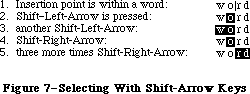 Figure 7–Selecting With Shift–Arrow Keys
In a text application, pressing Option–Shift and either Left Arrow or Right Arrow selects the entire word containing the character to the left of the insertion point. Assuming Left Arrow was used, the anchor point is at the right end of the word, the active end at the left. Each subsequent Option–Shift–Left Arrow adds another word to the left end of the selection, as shown in Figure 8.
Figure 7–Selecting With Shift–Arrow Keys
In a text application, pressing Option–Shift and either Left Arrow or Right Arrow selects the entire word containing the character to the left of the insertion point. Assuming Left Arrow was used, the anchor point is at the right end of the word, the active end at the left. Each subsequent Option–Shift–Left Arrow adds another word to the left end of the selection, as shown in Figure 8.
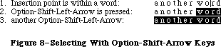 Figure 8–Selecting With Option–Shift–Arrow Keys
Pressing Command–Shift–Left Arrow selects the area from the insertion point to the left edge of the window. The anchor point is at the right end of the selection, the active end is at the left. Each subsequent Command–Shift–Left Arrow moves the document one windowful left and extends the selection to the left edge of the new window.
_______________________________________________________________________________
»Extending or Shrinking a Selection
To use arrow keys to extend or shrink a selection, the user holds down the Shift key (plus any defined modifiers) while pressing an arrow key. The arrow key moves the insertion point at the active end of the selection.
_______________________________________________________________________________
»Collapsing a Selection
When a block of text is selected, pressing either Left Arrow or Right Arrow deselects the range. If Left Arrow is pressed, the insertion point is left at the beginning of the previous selection; if Right Arrow, at the end of the previous selection.
_______________________________________________________________________________
»THE MOUSE
_______________________________________________________________________________
The mouse is a small device the size of a deck of playing cards, connected to the computer by a long, flexible cable. There’s a button on the top of the mouse. The user holds the mouse and rolls it on a flat, smooth surface. A pointer on the screen follows the motion of the mouse.
Simply moving the mouse results only in a corresponding movement of the pointer and no other action. Most actions take place when the user positions the “hot spot” of the pointer over an object on the screen and presses and releases the mouse button. The hot spot should be intuitive, like the point of an arrow or the center of a crossbar.
_______________________________________________________________________________
»Mouse Actions
The three basic mouse actions are:
• clicking: positioning the pointer with the mouse, and briefly
pressing and releasing the mouse button without moving the mouse
• pressing: positioning the pointer with the mouse, and holding
down the mouse button without moving the mouse
• dragging: positioning the pointer with the mouse, holding down
the mouse button, moving the mouse to a new position, and releasing
the button
The system provides “mouse-ahead”; that is, any mouse actions the user performs when the application isn’t ready to process them are saved in a buffer and can be processed at the application’s convenience. Alternatively, the application can choose to ignore saved-up mouse actions, but should do so only to protect the user from possibly damaging consequences.
Clicking something with the mouse performs an instantaneous action, such as selecting a location within a document or activating an object.
For certain kinds of objects, pressing on the object has the same effect as clicking it repeatedly. For example, clicking a scroll arrow causes a document to scroll one line; pressing on a scroll arrow causes the document to scroll repeatedly until the mouse button is released or the end of the document is reached.
Dragging can have different effects, depending on what’s under the pointer when the mouse button is pressed. The uses of dragging include choosing a menu item, selecting a range of objects, moving an object from one place to another, and shrinking or expanding an object.
Some objects, especially graphic objects, can be moved by dragging. In this case, the application attaches a dotted outline of the object to the pointer and moves the outline as the user moves the pointer. When the user releases the mouse button, the application redraws the complete object at the new location.
An object being moved can be restricted to certain boundaries, such as the edges of a window. If the user moves the pointer outside of the boundaries, the application stops drawing the dotted outline of the object. If the user releases the mouse button while the pointer is outside of the boundaries, the object isn’t moved. If, on the other hand, the user moves the pointer back within the boundaries again before releasing the mouse button, the outline is drawn again.
In general, moving the mouse changes nothing except the location, and possibly the shape, of the pointer. Pressing the mouse button indicates the intention to do something, and releasing the button completes the action. Pressing by itself should have no effect except in well-defined areas, such as scroll arrows, where it has the same effect as repeated clicking.
»Multiple-Clicking
A variant of clicking involves performing a second click shortly after the end of an initial click. If the downstroke of the second click follows the upstroke of the first by a short amount of time (as set by the user in the Control
Panel), and if the locations of the two clicks are reasonably close together, the two clicks constitute a double-click. Its most common use is as a faster or easier way to perform an action that can also be performed in another way. For example, clicking twice on an icon is a faster way to open it than selecting it and choosing Open; clicking twice on a word to select it is faster than dragging through it.
To allow the software to distinguish efficiently between single clicks and double-clicks on objects that respond to both, an operation invoked by double-clicking an object must be an enhancement, superset, or extension of the feature invoked by single-clicking that object.
Triple-clicking is also possible; it should similarly represent an extension of a double-click.
_______________________________________________________________________________
»Changing Pointer Shapes
The pointer may change shape to give feedback on the range of activities that make sense in a particular area of the screen, in a current mode, or both:
• The result of any mouse action depends on the item under the pointer
when the mouse button is pressed. To emphasize the differences among
mouse actions, the pointer may assume different appearances in different
areas to indicate the actions possible in each area. This can be
distracting, however, and should be kept to a minimum.
• Where an application uses modes for different functions, the pointer
can be a different shape in each mode. For example, in MacPaint, the
pointer shape always reflects the active palette symbol.
During a particularly lengthy operation, when the user can do nothing but wait until the operation is completed, the pointer may change to indicate this. The standard pointer used for this purpose is a wristwatch.
Figure 9 shows some examples of pointers and their effect. An application can design additional pointers for other contexts.
Figure 8–Selecting With Option–Shift–Arrow Keys
Pressing Command–Shift–Left Arrow selects the area from the insertion point to the left edge of the window. The anchor point is at the right end of the selection, the active end is at the left. Each subsequent Command–Shift–Left Arrow moves the document one windowful left and extends the selection to the left edge of the new window.
_______________________________________________________________________________
»Extending or Shrinking a Selection
To use arrow keys to extend or shrink a selection, the user holds down the Shift key (plus any defined modifiers) while pressing an arrow key. The arrow key moves the insertion point at the active end of the selection.
_______________________________________________________________________________
»Collapsing a Selection
When a block of text is selected, pressing either Left Arrow or Right Arrow deselects the range. If Left Arrow is pressed, the insertion point is left at the beginning of the previous selection; if Right Arrow, at the end of the previous selection.
_______________________________________________________________________________
»THE MOUSE
_______________________________________________________________________________
The mouse is a small device the size of a deck of playing cards, connected to the computer by a long, flexible cable. There’s a button on the top of the mouse. The user holds the mouse and rolls it on a flat, smooth surface. A pointer on the screen follows the motion of the mouse.
Simply moving the mouse results only in a corresponding movement of the pointer and no other action. Most actions take place when the user positions the “hot spot” of the pointer over an object on the screen and presses and releases the mouse button. The hot spot should be intuitive, like the point of an arrow or the center of a crossbar.
_______________________________________________________________________________
»Mouse Actions
The three basic mouse actions are:
• clicking: positioning the pointer with the mouse, and briefly
pressing and releasing the mouse button without moving the mouse
• pressing: positioning the pointer with the mouse, and holding
down the mouse button without moving the mouse
• dragging: positioning the pointer with the mouse, holding down
the mouse button, moving the mouse to a new position, and releasing
the button
The system provides “mouse-ahead”; that is, any mouse actions the user performs when the application isn’t ready to process them are saved in a buffer and can be processed at the application’s convenience. Alternatively, the application can choose to ignore saved-up mouse actions, but should do so only to protect the user from possibly damaging consequences.
Clicking something with the mouse performs an instantaneous action, such as selecting a location within a document or activating an object.
For certain kinds of objects, pressing on the object has the same effect as clicking it repeatedly. For example, clicking a scroll arrow causes a document to scroll one line; pressing on a scroll arrow causes the document to scroll repeatedly until the mouse button is released or the end of the document is reached.
Dragging can have different effects, depending on what’s under the pointer when the mouse button is pressed. The uses of dragging include choosing a menu item, selecting a range of objects, moving an object from one place to another, and shrinking or expanding an object.
Some objects, especially graphic objects, can be moved by dragging. In this case, the application attaches a dotted outline of the object to the pointer and moves the outline as the user moves the pointer. When the user releases the mouse button, the application redraws the complete object at the new location.
An object being moved can be restricted to certain boundaries, such as the edges of a window. If the user moves the pointer outside of the boundaries, the application stops drawing the dotted outline of the object. If the user releases the mouse button while the pointer is outside of the boundaries, the object isn’t moved. If, on the other hand, the user moves the pointer back within the boundaries again before releasing the mouse button, the outline is drawn again.
In general, moving the mouse changes nothing except the location, and possibly the shape, of the pointer. Pressing the mouse button indicates the intention to do something, and releasing the button completes the action. Pressing by itself should have no effect except in well-defined areas, such as scroll arrows, where it has the same effect as repeated clicking.
»Multiple-Clicking
A variant of clicking involves performing a second click shortly after the end of an initial click. If the downstroke of the second click follows the upstroke of the first by a short amount of time (as set by the user in the Control
Panel), and if the locations of the two clicks are reasonably close together, the two clicks constitute a double-click. Its most common use is as a faster or easier way to perform an action that can also be performed in another way. For example, clicking twice on an icon is a faster way to open it than selecting it and choosing Open; clicking twice on a word to select it is faster than dragging through it.
To allow the software to distinguish efficiently between single clicks and double-clicks on objects that respond to both, an operation invoked by double-clicking an object must be an enhancement, superset, or extension of the feature invoked by single-clicking that object.
Triple-clicking is also possible; it should similarly represent an extension of a double-click.
_______________________________________________________________________________
»Changing Pointer Shapes
The pointer may change shape to give feedback on the range of activities that make sense in a particular area of the screen, in a current mode, or both:
• The result of any mouse action depends on the item under the pointer
when the mouse button is pressed. To emphasize the differences among
mouse actions, the pointer may assume different appearances in different
areas to indicate the actions possible in each area. This can be
distracting, however, and should be kept to a minimum.
• Where an application uses modes for different functions, the pointer
can be a different shape in each mode. For example, in MacPaint, the
pointer shape always reflects the active palette symbol.
During a particularly lengthy operation, when the user can do nothing but wait until the operation is completed, the pointer may change to indicate this. The standard pointer used for this purpose is a wristwatch.
Figure 9 shows some examples of pointers and their effect. An application can design additional pointers for other contexts.
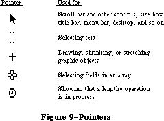 Figure 9–Pointers
_______________________________________________________________________________
»SELECTING
_______________________________________________________________________________
The user selects an object to distinguish it from other objects, just before performing an operation on it. Selecting the object of an operation before identifying the operation is a fundamental characteristic of the Macintosh user interface, since it allows the application to avoid modes.
Selecting an object has no effect on the contents of a document. Making a selection shouldn’t commit the user to anything; there should never be a penalty for making an incorrect selection. The user fixes an incorrect selection by making the correct selection.
Although there’s a variety of ways to select objects, they fall into easily recognizable groups. Users get used to doing specific things to select objects, and applications that use these methods are therefore easier to learn. Some of these methods apply to every type of application, and some only to particular types of applications.
This section discusses first the general methods, and then the specific methods that apply to text applications, graphics applications, and arrays. Figure 10 shows a comparison of some of the general methods.
__________________________________________________________________
»Selection by Clicking
The most straightforward method of selecting an object is by clicking on it once. Most things that can be selected in Macintosh applications can be selected this way.
Figure 9–Pointers
_______________________________________________________________________________
»SELECTING
_______________________________________________________________________________
The user selects an object to distinguish it from other objects, just before performing an operation on it. Selecting the object of an operation before identifying the operation is a fundamental characteristic of the Macintosh user interface, since it allows the application to avoid modes.
Selecting an object has no effect on the contents of a document. Making a selection shouldn’t commit the user to anything; there should never be a penalty for making an incorrect selection. The user fixes an incorrect selection by making the correct selection.
Although there’s a variety of ways to select objects, they fall into easily recognizable groups. Users get used to doing specific things to select objects, and applications that use these methods are therefore easier to learn. Some of these methods apply to every type of application, and some only to particular types of applications.
This section discusses first the general methods, and then the specific methods that apply to text applications, graphics applications, and arrays. Figure 10 shows a comparison of some of the general methods.
__________________________________________________________________
»Selection by Clicking
The most straightforward method of selecting an object is by clicking on it once. Most things that can be selected in Macintosh applications can be selected this way.
 Figure 10–Selection Methods
Some applications support selection by double-clicking and triple-clicking. As always with multiple clicks, the second click extends the effect of the first click, and the third click extends the effect of the second click. In the case of selection, this means that the second click selects the same sort of thing as the first click, only more of them. The same holds true for the third click.
For example, in text, the first click selects an insertion point, whereas the second click selects a whole word. The third click might select a whole block or paragraph of text. In graphics, the first click selects a single object, and double- and triple-clicks might select increasingly larger groups of objects.
_______________________________________________________________________________
»Range Selection
The user selects a range of objects by dragging through them. Although the exact meaning of the selection depends on the type of application, the procedure is always the same:
1. The user positions the pointer at one corner of the range and presses
the mouse button. This position is called the anchor point of the range.
2. The user moves the pointer in any direction. As the pointer is moved,
visual feedback indicates the objects that would be selected if the
mouse button were released. For text and arrays, the selected area is
continually highlighted. For graphics, a dotted rectangle expands or
contracts to show the range that will be selected.
3. When the feedback shows the desired range, the user releases the mouse
button. The point at which the button is released is called the endpoint
of the range.
_______________________________________________________________________________
»Extending a Selection
A user can change the extent of an existing selection by holding down the Shift key and clicking the mouse button. Exactly what happens next depends on the context.
In text or an array, the result of a Shift-click is always a range. The position where the button is clicked becomes the new endpoint or anchor point of the range; the selection can be extended in any direction. If the user clicks within the current range, the new range will be smaller than the old range.
In graphics, a selection is extended by adding objects to it; the added objects do not have to be adjacent to the objects already selected. The user can add either an individual object or a range of objects to the selection by holding down the Shift key before making the additional selection. If the user holds down the Shift key and selects one or more objects that are already highlighted, the objects are deselected.
Extended selections can be made across the panes of a split window. (See
“Splitting Windows”.)
_______________________________________________________________________________
»Making a Discontinuous Selection
In graphics applications, objects aren’t usually considered to be in any particular sequence. Therefore, the user can use Shift-click to extend a selection by a single object, even if that object is nowhere near the current selection. When this happens, the objects between the current selection and the new object are not automatically included in the selection. This kind of selection is called a discontinuous selection. In the case of graphics, all selections are discontinuous selections.
This is not the case with arrays and text, however. In these two kinds of applications, an extended selection made by a Shift-click always includes everything between the old selection and the new endpoint. To provide the possibility of a discontinuous selection in these applications, Command-click is included in the user interface.
To make a discontinuous selection in a text or array application, the user selects the first piece in the normal way, then holds down the Command key before selecting the remaining pieces. Each piece is selected in the same way as if it were the whole selection, but because the Command key is held down, the new pieces are added to the existing selection instead of supplanting it.
If one of the pieces selected is already within an existing part of the selection, then instead of being added to the selection it’s removed from the selection. Figure 11 shows a sequence in which several pieces are selected and deselected.
Not all applications support discontinuous selections, and those that do might restrict the operations that a user can perform on them. For example, a word processor might allow the user to choose a font after making a discontinuous selection, but not to choose Cut.
Figure 10–Selection Methods
Some applications support selection by double-clicking and triple-clicking. As always with multiple clicks, the second click extends the effect of the first click, and the third click extends the effect of the second click. In the case of selection, this means that the second click selects the same sort of thing as the first click, only more of them. The same holds true for the third click.
For example, in text, the first click selects an insertion point, whereas the second click selects a whole word. The third click might select a whole block or paragraph of text. In graphics, the first click selects a single object, and double- and triple-clicks might select increasingly larger groups of objects.
_______________________________________________________________________________
»Range Selection
The user selects a range of objects by dragging through them. Although the exact meaning of the selection depends on the type of application, the procedure is always the same:
1. The user positions the pointer at one corner of the range and presses
the mouse button. This position is called the anchor point of the range.
2. The user moves the pointer in any direction. As the pointer is moved,
visual feedback indicates the objects that would be selected if the
mouse button were released. For text and arrays, the selected area is
continually highlighted. For graphics, a dotted rectangle expands or
contracts to show the range that will be selected.
3. When the feedback shows the desired range, the user releases the mouse
button. The point at which the button is released is called the endpoint
of the range.
_______________________________________________________________________________
»Extending a Selection
A user can change the extent of an existing selection by holding down the Shift key and clicking the mouse button. Exactly what happens next depends on the context.
In text or an array, the result of a Shift-click is always a range. The position where the button is clicked becomes the new endpoint or anchor point of the range; the selection can be extended in any direction. If the user clicks within the current range, the new range will be smaller than the old range.
In graphics, a selection is extended by adding objects to it; the added objects do not have to be adjacent to the objects already selected. The user can add either an individual object or a range of objects to the selection by holding down the Shift key before making the additional selection. If the user holds down the Shift key and selects one or more objects that are already highlighted, the objects are deselected.
Extended selections can be made across the panes of a split window. (See
“Splitting Windows”.)
_______________________________________________________________________________
»Making a Discontinuous Selection
In graphics applications, objects aren’t usually considered to be in any particular sequence. Therefore, the user can use Shift-click to extend a selection by a single object, even if that object is nowhere near the current selection. When this happens, the objects between the current selection and the new object are not automatically included in the selection. This kind of selection is called a discontinuous selection. In the case of graphics, all selections are discontinuous selections.
This is not the case with arrays and text, however. In these two kinds of applications, an extended selection made by a Shift-click always includes everything between the old selection and the new endpoint. To provide the possibility of a discontinuous selection in these applications, Command-click is included in the user interface.
To make a discontinuous selection in a text or array application, the user selects the first piece in the normal way, then holds down the Command key before selecting the remaining pieces. Each piece is selected in the same way as if it were the whole selection, but because the Command key is held down, the new pieces are added to the existing selection instead of supplanting it.
If one of the pieces selected is already within an existing part of the selection, then instead of being added to the selection it’s removed from the selection. Figure 11 shows a sequence in which several pieces are selected and deselected.
Not all applications support discontinuous selections, and those that do might restrict the operations that a user can perform on them. For example, a word processor might allow the user to choose a font after making a discontinuous selection, but not to choose Cut.
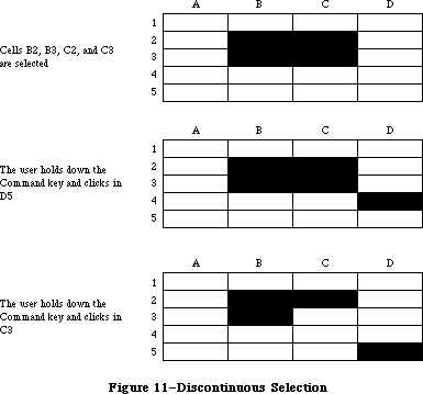 Figure 11–Discontinuous Selection
_______________________________________________________________________________
»Selecting Text
Text is used in most applications; it’s selected and edited in a consistent way, regardless of where it appears.
A block of text is a string of characters. A text selection is a substring of this string, which can have any length from zero characters to the whole block. Each of the text selection methods selects a different kind of substring. Figure 12 shows different kinds of text selections.
Figure 11–Discontinuous Selection
_______________________________________________________________________________
»Selecting Text
Text is used in most applications; it’s selected and edited in a consistent way, regardless of where it appears.
A block of text is a string of characters. A text selection is a substring of this string, which can have any length from zero characters to the whole block. Each of the text selection methods selects a different kind of substring. Figure 12 shows different kinds of text selections.
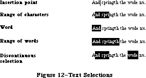 Figure 12–Text Selections
_______________________________________________________________________________
»Insertion Point
The insertion point is a zero-length text selection. The user establishes the location of the insertion point by clicking between two characters. The insertion point then appears at the nearest character boundary. If the user clicks to the right of the last character on a line, the insertion point appears immediately after the last character. The converse is true if the user clicks to the left of the first character in the line.
The insertion point shows where text will be inserted when the user begins typing, or where cut or copied data (the contents of the Clipboard) will be pasted. After each character is typed, the insertion point is relocated to the right of the insertion.
If, between the mouse-down and the mouse-up, the user moves the pointer more than about half the width of a character, the selection is a range selection rather than an insertion point.
_______________________________________________________________________________
»Selecting Words
The user selects a whole word by double-clicking somewhere within that word. If the user begins a double-click sequence, but then drags the mouse between the mouse-down and the mouse-up of the second click, the selection becomes a range of words rather than a single word. As the pointer moves, the application highlights or unhighlights a whole word at a time.
A word, or range of words, can also be selected in the same way as any other range; whether this type of selection is treated as a range of characters or as a range of words depends on the operation. For example, in MacWrite, a range of individual characters that happens to coincide with a range of words is treated like characters for purposes of extending a selection, but is treated like words for purposes of “intelligent” cut and paste (described later in the “Text Editing” section).
A word is defined as any continuous string that contains only the following characters:
• a letter (including letters with diacritical marks)
• a digit
• a nonbreaking space (Option-space)
• a dollar sign, cent sign, English pound symbol, or yen symbol
• a percent sign
• a comma between digits
• a period before a digit
• an apostrophe between letters or digits
• a hyphen, but not a minus sign (Option-hyphen) or a dash
(Option-Shift-hyphen)
This is the definition in the United States and Canada; in other countries, it would have to be changed to reflect local formats for numbers, dates, and currency.
If the user double-clicks over any character not on the list above, that character is selected, but it is not considered a word.
Examples of words:
$123,456.78
shouldn’t
3 1/2 [with a nonbreaking space]
.5%
Examples of nonwords:
7/10/6
blue cheese [with a breaking space]
“Yoicks!” [the quotation marks and exclamation point
aren’t part of the word]
_______________________________________________________________________________
»Selecting a Range of Text
The user selects a range of text by dragging through the range. A range is either a range of words or a range of individual characters, as described under “Selecting Words”, above.
If the user extends the range, the way the range is extended depends on what kind of range it is. If it’s a range of individual characters, it can be extended one character at a time. If it’s a range of words (including a single word), it’s extended only by whole words.
_______________________________________________________________________________
»Graphics Selections
There are several different ways to select graphic objects and to show selection feedback in existing Macintosh applications. MacDraw, MacPaint, and the Finder all illustrate different possibilities. This section describes the MacDraw paradigm, which is the most extensible to other kinds of applications.
A MacDraw document is a collection of individual graphic objects. To select one of these objects, the user clicks once on the object, which is then shown with knobs. (The knobs are used to stretch or shrink the object, and won’t be discussed in these guidelines.) Figure 13 shows some examples of selection.
Figure 12–Text Selections
_______________________________________________________________________________
»Insertion Point
The insertion point is a zero-length text selection. The user establishes the location of the insertion point by clicking between two characters. The insertion point then appears at the nearest character boundary. If the user clicks to the right of the last character on a line, the insertion point appears immediately after the last character. The converse is true if the user clicks to the left of the first character in the line.
The insertion point shows where text will be inserted when the user begins typing, or where cut or copied data (the contents of the Clipboard) will be pasted. After each character is typed, the insertion point is relocated to the right of the insertion.
If, between the mouse-down and the mouse-up, the user moves the pointer more than about half the width of a character, the selection is a range selection rather than an insertion point.
_______________________________________________________________________________
»Selecting Words
The user selects a whole word by double-clicking somewhere within that word. If the user begins a double-click sequence, but then drags the mouse between the mouse-down and the mouse-up of the second click, the selection becomes a range of words rather than a single word. As the pointer moves, the application highlights or unhighlights a whole word at a time.
A word, or range of words, can also be selected in the same way as any other range; whether this type of selection is treated as a range of characters or as a range of words depends on the operation. For example, in MacWrite, a range of individual characters that happens to coincide with a range of words is treated like characters for purposes of extending a selection, but is treated like words for purposes of “intelligent” cut and paste (described later in the “Text Editing” section).
A word is defined as any continuous string that contains only the following characters:
• a letter (including letters with diacritical marks)
• a digit
• a nonbreaking space (Option-space)
• a dollar sign, cent sign, English pound symbol, or yen symbol
• a percent sign
• a comma between digits
• a period before a digit
• an apostrophe between letters or digits
• a hyphen, but not a minus sign (Option-hyphen) or a dash
(Option-Shift-hyphen)
This is the definition in the United States and Canada; in other countries, it would have to be changed to reflect local formats for numbers, dates, and currency.
If the user double-clicks over any character not on the list above, that character is selected, but it is not considered a word.
Examples of words:
$123,456.78
shouldn’t
3 1/2 [with a nonbreaking space]
.5%
Examples of nonwords:
7/10/6
blue cheese [with a breaking space]
“Yoicks!” [the quotation marks and exclamation point
aren’t part of the word]
_______________________________________________________________________________
»Selecting a Range of Text
The user selects a range of text by dragging through the range. A range is either a range of words or a range of individual characters, as described under “Selecting Words”, above.
If the user extends the range, the way the range is extended depends on what kind of range it is. If it’s a range of individual characters, it can be extended one character at a time. If it’s a range of words (including a single word), it’s extended only by whole words.
_______________________________________________________________________________
»Graphics Selections
There are several different ways to select graphic objects and to show selection feedback in existing Macintosh applications. MacDraw, MacPaint, and the Finder all illustrate different possibilities. This section describes the MacDraw paradigm, which is the most extensible to other kinds of applications.
A MacDraw document is a collection of individual graphic objects. To select one of these objects, the user clicks once on the object, which is then shown with knobs. (The knobs are used to stretch or shrink the object, and won’t be discussed in these guidelines.) Figure 13 shows some examples of selection.
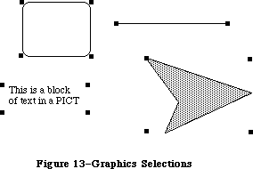 Figure 13–Graphics Selections
To select more than one object, the user can select either a range or a multiple selection. A range selection includes every object completely contained within the dotted rectangle that encloses the range, while an extended selection includes only those objects explicitly selected.
_______________________________________________________________________________
»Selections in Arrays
As described above under “Types of Applications”, an array is a one- or two-dimensional arrangement of fields. If the array is one-dimensional, it’s called a form; if it’s two-dimensional, it’s called a table. The user can select one or more fields, or part of the contents of a field.
To select a single field, the user clicks in the field. The user can also implicitly select a field by moving into it with the Tab or Return key.
The Tab key cycles through the fields in an order determined by the application. From each field, the Tab key selects the “next” field. Typically, the sequence of fields is first from left to right, and then from top to bottom. When the last field in a form is selected, pressing the Tab key selects the first field in the form. In a form, an application might prefer to select the fields in logical, rather than physical, order.
The Return key selects the first field in the next row. If the idea of rows doesn’t make sense in a particular context, then the Return key should have the same effect as the Tab key.
Tables are more likely than forms to support range selections and extended selections. A table can also support selection of rows and columns. The most convenient way for the user to select a column is to click in the column header. To select more than one column, the user drags through several column headers. The same applies to rows.
To select part of the contents of a field, the user must first select the field. The user then clicks again to select the desired part of the field. Since the contents of a field are either text or graphics, this type of selection follows the rules outlined above. Figure 14 shows some selections in an array.
Figure 13–Graphics Selections
To select more than one object, the user can select either a range or a multiple selection. A range selection includes every object completely contained within the dotted rectangle that encloses the range, while an extended selection includes only those objects explicitly selected.
_______________________________________________________________________________
»Selections in Arrays
As described above under “Types of Applications”, an array is a one- or two-dimensional arrangement of fields. If the array is one-dimensional, it’s called a form; if it’s two-dimensional, it’s called a table. The user can select one or more fields, or part of the contents of a field.
To select a single field, the user clicks in the field. The user can also implicitly select a field by moving into it with the Tab or Return key.
The Tab key cycles through the fields in an order determined by the application. From each field, the Tab key selects the “next” field. Typically, the sequence of fields is first from left to right, and then from top to bottom. When the last field in a form is selected, pressing the Tab key selects the first field in the form. In a form, an application might prefer to select the fields in logical, rather than physical, order.
The Return key selects the first field in the next row. If the idea of rows doesn’t make sense in a particular context, then the Return key should have the same effect as the Tab key.
Tables are more likely than forms to support range selections and extended selections. A table can also support selection of rows and columns. The most convenient way for the user to select a column is to click in the column header. To select more than one column, the user drags through several column headers. The same applies to rows.
To select part of the contents of a field, the user must first select the field. The user then clicks again to select the desired part of the field. Since the contents of a field are either text or graphics, this type of selection follows the rules outlined above. Figure 14 shows some selections in an array.
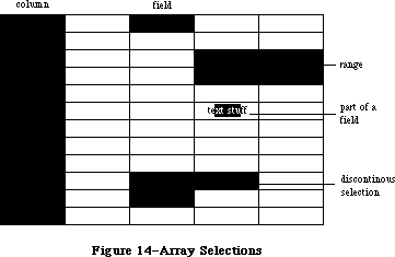 Figure 14–Array Selections
_______________________________________________________________________________
»WINDOWS
_______________________________________________________________________________
The rectangles on the desktop that display information are windows. The most commmon types of windows are document windows, desk accessories, dialog boxes, and alert boxes. (Dialog and alert boxes are discussed under “Dialogs and Alerts”.) Some of the features described in this section are applicable only to document windows. Figure 15 shows a typical active document window and some of its components.
Figure 14–Array Selections
_______________________________________________________________________________
»WINDOWS
_______________________________________________________________________________
The rectangles on the desktop that display information are windows. The most commmon types of windows are document windows, desk accessories, dialog boxes, and alert boxes. (Dialog and alert boxes are discussed under “Dialogs and Alerts”.) Some of the features described in this section are applicable only to document windows. Figure 15 shows a typical active document window and some of its components.
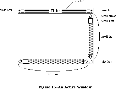 Figure 15–An Active Window
_______________________________________________________________________________
»Multiple Windows
Some applications may be able to keep several windows on the desktop at the same time. Each window is in a different plane. Windows can be moved around on the Macintosh’s desktop much like pieces of paper can be moved around on a real desktop. Each window can overlap those behind it, and can be overlapped by those in front of it. Even when windows don’t overlap, they retain their front-to-back ordering.
Different windows can represent separate documents being viewed or edited simultaneously, or related parts of a logical whole, like the listing, execution, and debugging of a program. Each application may deal with the meaning and creation of multiple windows in its own way.
The advantage of multiple windows is that the user can isolate unrelated chunks of information from each other. The disadvantage is that the desktop can become cluttered, especially if some of the windows can’t be moved. Figure 16 shows multiple windows.
Figure 15–An Active Window
_______________________________________________________________________________
»Multiple Windows
Some applications may be able to keep several windows on the desktop at the same time. Each window is in a different plane. Windows can be moved around on the Macintosh’s desktop much like pieces of paper can be moved around on a real desktop. Each window can overlap those behind it, and can be overlapped by those in front of it. Even when windows don’t overlap, they retain their front-to-back ordering.
Different windows can represent separate documents being viewed or edited simultaneously, or related parts of a logical whole, like the listing, execution, and debugging of a program. Each application may deal with the meaning and creation of multiple windows in its own way.
The advantage of multiple windows is that the user can isolate unrelated chunks of information from each other. The disadvantage is that the desktop can become cluttered, especially if some of the windows can’t be moved. Figure 16 shows multiple windows.
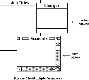 Figure 16–Multiple Windows
_______________________________________________________________________________
»Opening and Closing Windows
Windows come up onto the screen in different ways as appropriate to the purpose of the window. The application controls at least the initial size and placement of its windows.
Most windows have a close box that, when clicked, makes the window go away. The application in control of the window determines what’s done with the window visually and logically when the close box is clicked. Visually, the window can either shrink to a smaller object such as an icon, or leave no trace behind when it closes. Logically, the information in the window is either retained and then restored when the window is reopened (which is the usual case), or else the window is reinitialized each time it’s opened. When a document is closed, the user is given the choice whether to save any changes made to the document since the last time it was saved.
If an application doesn’t support closing a window with a close box, it
shouldn’t include a close box on the window.
_______________________________________________________________________________
»The Active Window
Of all the windows that are open on the desktop, the user can work in only one window at a time. This window is called the active window. All other open windows are inactive. To make a window active, the user clicks in it. Making a window active has two immediate consequences:
• The window changes its appearance: Its title bar is highlighted
and the scroll bars and size box are shown. If the window is being
reactivated, the selection that was in effect when it was deactivated
is rehighlighted.
• The window is moved to the frontmost plane, so that it’s shown in
front of any windows that it overlaps.
Clicking in a window does nothing except activate it. To make a selection in the window, the user must click again. When the user clicks in a window that has been deactivated, the window should be reinstated just the way it was when it was deactivated, with the same position of the scroll box, and the same selection highlighted.
When a window becomes inactive, all the visual changes that took place when it was activated are reversed. The title bar becomes unhighlighted, the scroll bars and size box aren’t shown, and no selection is shown in the window.
_______________________________________________________________________________
»Moving a Window
Each application initially places windows on the screen wherever it wants them. The user can move a window—to make more room on the desktop or to uncover a window it’s overlapping —by dragging it by its title bar. As soon as the user presses in the title bar, that window becomes the active window. A dotted outline of the window follows the pointer until the user releases the mouse button. At the release of the button the full window is drawn in its new location. Moving a window doesn’t affect the appearance of the document within the window.
If the user holds down the Command key while moving the window, the window
isn’t made active; it moves in the same plane.
The application should ensure that a window can never be moved completely off the screen.
_______________________________________________________________________________
»Changing the Size of a Window
If a window has a size box in its bottom right corner, where the scroll bars come together, the user can change the size of the window—enlarging or reducing it to the desired size.
Dragging the size box attaches a dotted outline of the window to the pointer. The outline’s top left corner stays fixed, while the bottom right corner follows the pointer. When the mouse button is released, the entire window is redrawn in the shape of the dotted outline.
Moving windows and sizing them go hand in hand. If a window can be moved, but not sized, then the user ends up constantly moving windows on and off the screen. The reason for this is that if the user moves the window off the right or bottom edge of the screen, the scroll bars are the first thing to disappear. To scroll the window, the user must move the window back onto the screen again. If, on the other hand, the window can be resized, then the user can change its size instead of moving it off the screen, and will still be able to scroll.
Sizing a window doesn’t change the position of the top left corner of the window over the document or the appearance of the part of the view that’s still showing; it changes only how much of the view is visible inside the window. One exception to this rule is a command such as Reduce to Fit in MacDraw, which changes the scaling of the view to fit the size of the window. If, after choosing this command, the user resizes the window, the application changes the scaling of the view.
The application can define a minimum window size. Any attempt to shrink the window below this size is ignored.
_______________________________________________________________________________
»Window Zooming
The more open documents on a desktop, the more difficult it is for the user to locate, select, and resize the one to be worked on. The 128K ROM includes a feature, known as window zooming, that allows users—with a single mouse click—to toggle the active window between its standard size and location and a predefined size and location.
The initial size and placement of a window is known as its standard state. The application program can supply values for the standard state; otherwise the full screen (minus a few border pixels) is assumed (see Figure 17). The standard state should be the most useful size and location for normal operations within the program—usually it’s the full screen.
Figure 16–Multiple Windows
_______________________________________________________________________________
»Opening and Closing Windows
Windows come up onto the screen in different ways as appropriate to the purpose of the window. The application controls at least the initial size and placement of its windows.
Most windows have a close box that, when clicked, makes the window go away. The application in control of the window determines what’s done with the window visually and logically when the close box is clicked. Visually, the window can either shrink to a smaller object such as an icon, or leave no trace behind when it closes. Logically, the information in the window is either retained and then restored when the window is reopened (which is the usual case), or else the window is reinitialized each time it’s opened. When a document is closed, the user is given the choice whether to save any changes made to the document since the last time it was saved.
If an application doesn’t support closing a window with a close box, it
shouldn’t include a close box on the window.
_______________________________________________________________________________
»The Active Window
Of all the windows that are open on the desktop, the user can work in only one window at a time. This window is called the active window. All other open windows are inactive. To make a window active, the user clicks in it. Making a window active has two immediate consequences:
• The window changes its appearance: Its title bar is highlighted
and the scroll bars and size box are shown. If the window is being
reactivated, the selection that was in effect when it was deactivated
is rehighlighted.
• The window is moved to the frontmost plane, so that it’s shown in
front of any windows that it overlaps.
Clicking in a window does nothing except activate it. To make a selection in the window, the user must click again. When the user clicks in a window that has been deactivated, the window should be reinstated just the way it was when it was deactivated, with the same position of the scroll box, and the same selection highlighted.
When a window becomes inactive, all the visual changes that took place when it was activated are reversed. The title bar becomes unhighlighted, the scroll bars and size box aren’t shown, and no selection is shown in the window.
_______________________________________________________________________________
»Moving a Window
Each application initially places windows on the screen wherever it wants them. The user can move a window—to make more room on the desktop or to uncover a window it’s overlapping —by dragging it by its title bar. As soon as the user presses in the title bar, that window becomes the active window. A dotted outline of the window follows the pointer until the user releases the mouse button. At the release of the button the full window is drawn in its new location. Moving a window doesn’t affect the appearance of the document within the window.
If the user holds down the Command key while moving the window, the window
isn’t made active; it moves in the same plane.
The application should ensure that a window can never be moved completely off the screen.
_______________________________________________________________________________
»Changing the Size of a Window
If a window has a size box in its bottom right corner, where the scroll bars come together, the user can change the size of the window—enlarging or reducing it to the desired size.
Dragging the size box attaches a dotted outline of the window to the pointer. The outline’s top left corner stays fixed, while the bottom right corner follows the pointer. When the mouse button is released, the entire window is redrawn in the shape of the dotted outline.
Moving windows and sizing them go hand in hand. If a window can be moved, but not sized, then the user ends up constantly moving windows on and off the screen. The reason for this is that if the user moves the window off the right or bottom edge of the screen, the scroll bars are the first thing to disappear. To scroll the window, the user must move the window back onto the screen again. If, on the other hand, the window can be resized, then the user can change its size instead of moving it off the screen, and will still be able to scroll.
Sizing a window doesn’t change the position of the top left corner of the window over the document or the appearance of the part of the view that’s still showing; it changes only how much of the view is visible inside the window. One exception to this rule is a command such as Reduce to Fit in MacDraw, which changes the scaling of the view to fit the size of the window. If, after choosing this command, the user resizes the window, the application changes the scaling of the view.
The application can define a minimum window size. Any attempt to shrink the window below this size is ignored.
_______________________________________________________________________________
»Window Zooming
The more open documents on a desktop, the more difficult it is for the user to locate, select, and resize the one to be worked on. The 128K ROM includes a feature, known as window zooming, that allows users—with a single mouse click—to toggle the active window between its standard size and location and a predefined size and location.
The initial size and placement of a window is known as its standard state. The application program can supply values for the standard state; otherwise the full screen (minus a few border pixels) is assumed (see Figure 17). The standard state should be the most useful size and location for normal operations within the program—usually it’s the full screen.
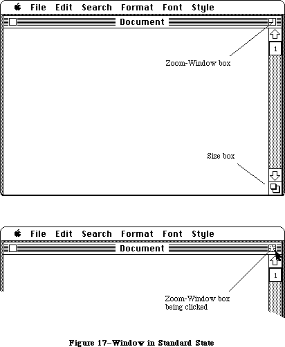 Figure 17–Window in Standard State
The user cannot change the standard state, but the application can change it within context. For example, a word processor might define a size that’s wide enough to display a document whose width is as specified in Page Setup. If the user invokes Page Setup to specify a wider or narrower document, the application might then change the standard state to reflect that change.
Your application can also supply initial values for the second window state, known as the user state. If you don’t supply initial values, the user state is identical to the standard state until the user moves or resizes the window. When the standard state and user state are different (Figure 18 shows a hypothetical user state), clicking in the zoom-window box acts as a toggle between the two states.
Figure 17–Window in Standard State
The user cannot change the standard state, but the application can change it within context. For example, a word processor might define a size that’s wide enough to display a document whose width is as specified in Page Setup. If the user invokes Page Setup to specify a wider or narrower document, the application might then change the standard state to reflect that change.
Your application can also supply initial values for the second window state, known as the user state. If you don’t supply initial values, the user state is identical to the standard state until the user moves or resizes the window. When the standard state and user state are different (Figure 18 shows a hypothetical user state), clicking in the zoom-window box acts as a toggle between the two states.
 Figure 18–Window in User State
Application developers are encouraged to take advantage of the zoom-window feature; details on using this feature are provided in the Window Manager chapter. You should not change the shape of the zoom-window box or change the interpretation of clicking on the the zoom-window box (shown in Figure 19). You should add no other elements to the title bar. Except in the zoom-window box and in the close box, clicking within the title bar should have no effect.
Figure 18–Window in User State
Application developers are encouraged to take advantage of the zoom-window feature; details on using this feature are provided in the Window Manager chapter. You should not change the shape of the zoom-window box or change the interpretation of clicking on the the zoom-window box (shown in Figure 19). You should add no other elements to the title bar. Except in the zoom-window box and in the close box, clicking within the title bar should have no effect.
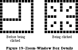 Figure 19–Zoom-Window Box Details
»Effects of Dragging and Sizing
Explicit dragging or resizing of the window is handled in the normal way, regardless of the presence or absence of the zoom-window feature. The effect of dragging or resizing depends on the state of the window and the degree of movement. A change, either in position or size, of seven pixels or less is insignificant. A change of more than seven pixels is a “significant change”.
If dragging or resizing occur when the window is in the standard state, a small change in the size or location of the window does not change the state, nor does it change the application-defined values for the size and location of the standard state. It does, of course, change the size or location of the window. A significant change in the size or location of the window switches the window to the user state and sets the values for the size and location of that state to those of the window.
If dragging or resizing occur when the window is in the user state, a change in size or location that leaves the window within seven pixels of the size and location specified as the standard state changes the state to the standard state, leaving the size and location of the user state unchanged. Any other change in size or location in the user state leaves the window in the user state and sets the values for the size and location of that state to those of the window.
_______________________________________________________________________________
»Scroll Bars
Scroll bars are used to change which part of a document view is shown in a window. Only the active window can be scrolled.
A scroll bar (see Figure 15) is a light gray shaft, capped on each end with square boxes labeled with arrows; inside the shaft is a white rectangle. The shaft represents one dimension of the entire document; the white rectangle
(called the scroll box) represents the location of the portion of the document currently visible inside the window. As the user moves the document under the window, the position of the rectangle in the scroll bar moves correspondingly. If the document is no larger than the window, the scroll bars are inactive (the scrolling apparatus isn’t shown in them). If the document window is inactive, the scroll bars aren’t shown at all.
There are three ways to move the document under the window: by sequential scrolling, by “paging” windowful by windowful through the document, and by directly positioning the scroll box.
Clicking a scroll arrow lets the user see more of the document in the direction of the scroll arrow, so it moves the document in the opposite direction from the arrow. For example, when the user clicks the top scroll arrow, the document moves down, bringing the view closer to the top of the document. The scroll box moves towards the arrow being clicked.
Each click in a scroll arrow causes movement a distance of one unit in the chosen direction, with the unit of distance being appropriate to the application: one line for a word processor, one row or column for a spreadsheet, and so on. Within a document, units should always be the same size, for smooth scrolling. Pressing the scroll arrow causes continuous movement in its direction.
Clicking the mouse anywhere in the gray area of the scroll bar advances the document by windowfuls. The scroll box, and the document view, move toward the place where the user clicked. Clicking below the scroll box, for example, brings the user the next windowful towards the bottom of the document. Pressing in the gray area keeps windowfuls flipping by until the user releases the mouse button, or until the location of the scroll box catches up to the location of the pointer. Each windowful is the height or width of the window, minus one unit overlap (where a unit is the distance the view scrolls when the scroll arrow is clicked once).
In both the above schemes, the user moves the document incrementally until it’s in the proper position under the window; as the document moves, the scroll box moves accordingly. The user can also move the document directly to any position simply by moving the scroll box to the corresponding position in the scroll bar. To move the scroll box, the user drags it along the scroll bar; an outline of the scroll box follows the pointer. When the mouse button is released, the scroll box jumps to the position last held by the outline, and the document jumps to the position corresponding to the new position of the scroll box.
If the user starts dragging the scroll box, and then moves the pointer a certain distance outside the scroll bar, the scroll box detaches itself from the pointer and stops following it; if the user releases the mouse button, the scroll box stays in its original position and the document remains unmoved. But if the user still holds the mouse button and drags the pointer back into the scroll bar, the scroll box reattaches itself to the pointer and can be dragged as usual.
If a document has a fixed size, and the user scrolls to the right or bottom edge of the document, the application displays a gray background between the edge of the document and the window frame.
_______________________________________________________________________________
»Automatic Scrolling
There are several instances when the application, rather than the user, scrolls the document. These instances involve some potentially sticky problems about how to position the document within the window after scrolling.
The first case is when the user moves the pointer out of the window while selecting by dragging. The window keeps up with the selection by scrolling automatically in the direction the pointer has been moved. The rate of scrolling is the same as if the user were pressing on the corresponding scroll arrow or arrows.
The second case is when the selection isn’t currently showing in the window, and the user performs an operation on it. When this happens, it’s usually because the user has scrolled the document after making a selection. In this case, the application scrolls the window so that the selection is showing before performing the operation.
The third case is when the application performs an operation whose side effect is to make a new selection. An example is a search operation, after which the object of the search is selected. If this object isn’t showing in the window, the application must scroll the document so as to show it.
The second and third cases present the same problem: Where should the selection be positioned within the window after scrolling? The primary rule is that the application should avoid unnecessary scrolling; users prefer to retain control over the positioning of a document. The following guidelines should be helpful:
• If part of the new selection is already showing in the window, don’t
scroll at all. An exception to this rule is when the part of the
selection that isn’t showing is more important than the part that is
showing.
• If scrolling in one orientation (horizontal or vertical) is sufficient
to reveal the selection, don’t scroll in both orientations.
• If the selection is smaller than the window, position the selection so
that some of its context is showing on each side. It’s better to put
the selection somewhere near the middle of the window than right up
against the corner.
• Even if the selection is too large to show in the window, it might be
preferable to show some context rather than to try to fit as much as
possible of the selection in the window.
_______________________________________________________________________________
»Splitting a Window
Sometimes it’s desirable to be able to see disjoint parts of a document simultaneously. Applications that accommodate such a capability allow the window to be split into independently scrollable panes.
Applications that support splitting a window into panes place split bars at the top of the vertical scroll bar and to the left of the horizontal one. Pressing a split bar attaches it to the pointer. Dragging the split bar positions it anywhere along the scroll bar; releasing the mouse button moves the split bar to a new position, splits the window at that location, and divides the appropriate scroll bar into separate scroll bars for each pane. Figure 20 shows the ways a window can be split.
Figure 19–Zoom-Window Box Details
»Effects of Dragging and Sizing
Explicit dragging or resizing of the window is handled in the normal way, regardless of the presence or absence of the zoom-window feature. The effect of dragging or resizing depends on the state of the window and the degree of movement. A change, either in position or size, of seven pixels or less is insignificant. A change of more than seven pixels is a “significant change”.
If dragging or resizing occur when the window is in the standard state, a small change in the size or location of the window does not change the state, nor does it change the application-defined values for the size and location of the standard state. It does, of course, change the size or location of the window. A significant change in the size or location of the window switches the window to the user state and sets the values for the size and location of that state to those of the window.
If dragging or resizing occur when the window is in the user state, a change in size or location that leaves the window within seven pixels of the size and location specified as the standard state changes the state to the standard state, leaving the size and location of the user state unchanged. Any other change in size or location in the user state leaves the window in the user state and sets the values for the size and location of that state to those of the window.
_______________________________________________________________________________
»Scroll Bars
Scroll bars are used to change which part of a document view is shown in a window. Only the active window can be scrolled.
A scroll bar (see Figure 15) is a light gray shaft, capped on each end with square boxes labeled with arrows; inside the shaft is a white rectangle. The shaft represents one dimension of the entire document; the white rectangle
(called the scroll box) represents the location of the portion of the document currently visible inside the window. As the user moves the document under the window, the position of the rectangle in the scroll bar moves correspondingly. If the document is no larger than the window, the scroll bars are inactive (the scrolling apparatus isn’t shown in them). If the document window is inactive, the scroll bars aren’t shown at all.
There are three ways to move the document under the window: by sequential scrolling, by “paging” windowful by windowful through the document, and by directly positioning the scroll box.
Clicking a scroll arrow lets the user see more of the document in the direction of the scroll arrow, so it moves the document in the opposite direction from the arrow. For example, when the user clicks the top scroll arrow, the document moves down, bringing the view closer to the top of the document. The scroll box moves towards the arrow being clicked.
Each click in a scroll arrow causes movement a distance of one unit in the chosen direction, with the unit of distance being appropriate to the application: one line for a word processor, one row or column for a spreadsheet, and so on. Within a document, units should always be the same size, for smooth scrolling. Pressing the scroll arrow causes continuous movement in its direction.
Clicking the mouse anywhere in the gray area of the scroll bar advances the document by windowfuls. The scroll box, and the document view, move toward the place where the user clicked. Clicking below the scroll box, for example, brings the user the next windowful towards the bottom of the document. Pressing in the gray area keeps windowfuls flipping by until the user releases the mouse button, or until the location of the scroll box catches up to the location of the pointer. Each windowful is the height or width of the window, minus one unit overlap (where a unit is the distance the view scrolls when the scroll arrow is clicked once).
In both the above schemes, the user moves the document incrementally until it’s in the proper position under the window; as the document moves, the scroll box moves accordingly. The user can also move the document directly to any position simply by moving the scroll box to the corresponding position in the scroll bar. To move the scroll box, the user drags it along the scroll bar; an outline of the scroll box follows the pointer. When the mouse button is released, the scroll box jumps to the position last held by the outline, and the document jumps to the position corresponding to the new position of the scroll box.
If the user starts dragging the scroll box, and then moves the pointer a certain distance outside the scroll bar, the scroll box detaches itself from the pointer and stops following it; if the user releases the mouse button, the scroll box stays in its original position and the document remains unmoved. But if the user still holds the mouse button and drags the pointer back into the scroll bar, the scroll box reattaches itself to the pointer and can be dragged as usual.
If a document has a fixed size, and the user scrolls to the right or bottom edge of the document, the application displays a gray background between the edge of the document and the window frame.
_______________________________________________________________________________
»Automatic Scrolling
There are several instances when the application, rather than the user, scrolls the document. These instances involve some potentially sticky problems about how to position the document within the window after scrolling.
The first case is when the user moves the pointer out of the window while selecting by dragging. The window keeps up with the selection by scrolling automatically in the direction the pointer has been moved. The rate of scrolling is the same as if the user were pressing on the corresponding scroll arrow or arrows.
The second case is when the selection isn’t currently showing in the window, and the user performs an operation on it. When this happens, it’s usually because the user has scrolled the document after making a selection. In this case, the application scrolls the window so that the selection is showing before performing the operation.
The third case is when the application performs an operation whose side effect is to make a new selection. An example is a search operation, after which the object of the search is selected. If this object isn’t showing in the window, the application must scroll the document so as to show it.
The second and third cases present the same problem: Where should the selection be positioned within the window after scrolling? The primary rule is that the application should avoid unnecessary scrolling; users prefer to retain control over the positioning of a document. The following guidelines should be helpful:
• If part of the new selection is already showing in the window, don’t
scroll at all. An exception to this rule is when the part of the
selection that isn’t showing is more important than the part that is
showing.
• If scrolling in one orientation (horizontal or vertical) is sufficient
to reveal the selection, don’t scroll in both orientations.
• If the selection is smaller than the window, position the selection so
that some of its context is showing on each side. It’s better to put
the selection somewhere near the middle of the window than right up
against the corner.
• Even if the selection is too large to show in the window, it might be
preferable to show some context rather than to try to fit as much as
possible of the selection in the window.
_______________________________________________________________________________
»Splitting a Window
Sometimes it’s desirable to be able to see disjoint parts of a document simultaneously. Applications that accommodate such a capability allow the window to be split into independently scrollable panes.
Applications that support splitting a window into panes place split bars at the top of the vertical scroll bar and to the left of the horizontal one. Pressing a split bar attaches it to the pointer. Dragging the split bar positions it anywhere along the scroll bar; releasing the mouse button moves the split bar to a new position, splits the window at that location, and divides the appropriate scroll bar into separate scroll bars for each pane. Figure 20 shows the ways a window can be split.
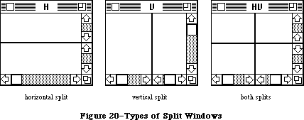 Figure 20–Types of Split Windows
After a split, the document appears the same, except for the split line lying across it. But there are now separate scroll bars for each pane. The panes are still scrolled together in the orientation of the split, but can be scrolled independently in the other orientation. For example, if the split is vertical, then vertical scrolling (using the scroll bar along the right of the window) is still synchronous; horizontal scrolling is controlled separately for each pane, using the two scroll bars along the bottom of the window. This is shown in Figure 21.
Figure 20–Types of Split Windows
After a split, the document appears the same, except for the split line lying across it. But there are now separate scroll bars for each pane. The panes are still scrolled together in the orientation of the split, but can be scrolled independently in the other orientation. For example, if the split is vertical, then vertical scrolling (using the scroll bar along the right of the window) is still synchronous; horizontal scrolling is controlled separately for each pane, using the two scroll bars along the bottom of the window. This is shown in Figure 21.
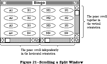 Figure 21–Scrolling a Split Window
To remove a split, the user drags the split bar to either end of the scroll bar.
The number of views in a document doesn’t alter the number of selections per document: that is, one. The selection appears highlighted in all views that show it. If the application has to scroll automatically to show the selection, the pane that should be scrolled is the last one that the user clicked in. If the selection is already showing in one of the panes, no automatic scrolling takes place.
_______________________________________________________________________________
»Panels
If a document window is more or less permanently divided into different areas, each of which has different content, these areas are called panels. Unlike panes, which show different parts of the same document but are functionally identical, panels are functionally different from each other but might show different interpretations of the same part of the document. For example, one panel might show a graphic version of the document while another panel shows a textual version.
Panels can behave much like windows; they can have scroll bars, and can even be split into more than one pane. An example of a panel with scroll bars is the list of files in the Open command’s dialog box.
Whether to use panels instead of separate windows is up to the application. Multiple panels in the same window are more compact than separate windows, but they have to be moved, opened, and closed as a unit.
_______________________________________________________________________________
»COMMANDS
_______________________________________________________________________________
Once information that’s to be operated on has been selected, a command to operate on the information can be chosen from lists of commands called menus.
Macintosh’s pull-down menus have the advantage that they’re not visible until the user wants to see them; at the same time they’re easy for the user to see and choose items from.
Most commands either do something, in which case they’re verbs or verb phrases, or else they specify an attribute of an object, in which case they’re adjectives. They usually apply to the current selection, although some commands apply to the whole document or window.
When you’re designing your application, don’t assume that everything has to be done through menu commands. Sometimes it’s more appropriate for an operation to take place as a result of direct user manipulation of a graphic object on the screen, such as a control or icon. Alternatively, a single command can execute complicated instructions if it brings up a dialog box for the user to fill in.
_______________________________________________________________________________
»The Menu Bar
The menu bar is displayed at the top of the screen. It contains a number of words and phrases: These are the titles of the menus associated with the current application. Each application has its own menu bar. The names of the menus do not change, except when the user accesses a desk accessory that uses different menus.
Only menu titles appear in the menu bar. If all of the commands in a menu are currently disabled (that is, the user can’t choose them), the menu title should be dimmed (drawn in gray). The user can pull down the menu to see the commands, but can’t choose any of them.
_______________________________________________________________________________
»Choosing a Menu Command
To choose a command, the user positions the pointer over the menu title and presses the mouse button. The application highlights the title and displays the menu, as shown in Figure 22.
While holding down the mouse button, the user moves the pointer down the menu. As the pointer moves to each command, the command is highlighted. The command that’s highlighted when the user releases the mouse button is chosen. As soon as the mouse button is released, the command blinks briefly, the menu disappears, and the command is executed. (The user can set the number of times the command blinks in the Control Panel desk accessory.) The menu title in the menu bar remains highlighted until the command has completed execution.
Nothing actually happens until the user chooses the command; the user can look at any of the menus without making a commitment to do anything.
The most frequently used commands should be at the top of a menu; research shows that the easiest item for the user to choose is the second item from the top. The most dangerous commands should be at the bottom of the menu, preferably isolated from the frequently used commands.
Figure 21–Scrolling a Split Window
To remove a split, the user drags the split bar to either end of the scroll bar.
The number of views in a document doesn’t alter the number of selections per document: that is, one. The selection appears highlighted in all views that show it. If the application has to scroll automatically to show the selection, the pane that should be scrolled is the last one that the user clicked in. If the selection is already showing in one of the panes, no automatic scrolling takes place.
_______________________________________________________________________________
»Panels
If a document window is more or less permanently divided into different areas, each of which has different content, these areas are called panels. Unlike panes, which show different parts of the same document but are functionally identical, panels are functionally different from each other but might show different interpretations of the same part of the document. For example, one panel might show a graphic version of the document while another panel shows a textual version.
Panels can behave much like windows; they can have scroll bars, and can even be split into more than one pane. An example of a panel with scroll bars is the list of files in the Open command’s dialog box.
Whether to use panels instead of separate windows is up to the application. Multiple panels in the same window are more compact than separate windows, but they have to be moved, opened, and closed as a unit.
_______________________________________________________________________________
»COMMANDS
_______________________________________________________________________________
Once information that’s to be operated on has been selected, a command to operate on the information can be chosen from lists of commands called menus.
Macintosh’s pull-down menus have the advantage that they’re not visible until the user wants to see them; at the same time they’re easy for the user to see and choose items from.
Most commands either do something, in which case they’re verbs or verb phrases, or else they specify an attribute of an object, in which case they’re adjectives. They usually apply to the current selection, although some commands apply to the whole document or window.
When you’re designing your application, don’t assume that everything has to be done through menu commands. Sometimes it’s more appropriate for an operation to take place as a result of direct user manipulation of a graphic object on the screen, such as a control or icon. Alternatively, a single command can execute complicated instructions if it brings up a dialog box for the user to fill in.
_______________________________________________________________________________
»The Menu Bar
The menu bar is displayed at the top of the screen. It contains a number of words and phrases: These are the titles of the menus associated with the current application. Each application has its own menu bar. The names of the menus do not change, except when the user accesses a desk accessory that uses different menus.
Only menu titles appear in the menu bar. If all of the commands in a menu are currently disabled (that is, the user can’t choose them), the menu title should be dimmed (drawn in gray). The user can pull down the menu to see the commands, but can’t choose any of them.
_______________________________________________________________________________
»Choosing a Menu Command
To choose a command, the user positions the pointer over the menu title and presses the mouse button. The application highlights the title and displays the menu, as shown in Figure 22.
While holding down the mouse button, the user moves the pointer down the menu. As the pointer moves to each command, the command is highlighted. The command that’s highlighted when the user releases the mouse button is chosen. As soon as the mouse button is released, the command blinks briefly, the menu disappears, and the command is executed. (The user can set the number of times the command blinks in the Control Panel desk accessory.) The menu title in the menu bar remains highlighted until the command has completed execution.
Nothing actually happens until the user chooses the command; the user can look at any of the menus without making a commitment to do anything.
The most frequently used commands should be at the top of a menu; research shows that the easiest item for the user to choose is the second item from the top. The most dangerous commands should be at the bottom of the menu, preferably isolated from the frequently used commands.
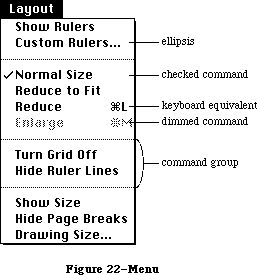 Figure 22–Menu
_______________________________________________________________________________
»Appearance of Menu Commands
The commands in a particular menu should be logically related to the title of the menu. In addition to command names, three features of menus help the user understand what each command does: command groups, toggles, and special visual features.
»Command Groups
As mentioned above, menu commands can be divided into two kinds: verbs and adjectives, or actions and attributes. An important difference between the two kinds of commands is that an attribute stays in effect until it’s canceled, while an action ceases to be relevant after it has been performed. Each of these two kinds can be grouped within a menu. Groups are separated by dotted lines, which are implemented as disabled commands.
The most basic reason to group commands is to break up a menu so it’s easier to read. Commands grouped for this reason are logically related, but independent. Commands that are actions are usually grouped this way, such as Cut, Copy, Paste, and Clear in the Edit menu.
Attribute commands that are interdependent are grouped to show this interdependence. Two kinds of attribute command groups are mutually exclusive groups and accumulating groups.
In a mutually exclusive attribute group, only one command in the group is in effect at any time. The command that’s in effect is preceded by a check mark. If the user chooses a different command in the group, the check mark is moved to the new command. An example is the Font menu in MacWrite; no more than one font can be in effect at a time.
In an accumulating attribute group, any number of attributes can be in effect at the same time. One special command in the group cancels all the other commands. An example is the Style menu in MacWrite: The user can choose any combination of Bold, Italic, Underline, Outline, or Shadow, but Plain Text cancels all the other commands.
»Toggled Commands
Another way to show the presence or absence of an attribute is by a toggled command. In this case, the attribute has two states, and a single command allows the user to toggle between the states. For example, when rulers are showing in MacWrite, a command in the Format menu reads “Hide Rulers”. If the user chooses this command, the rulers are hidden, and the command is changed to read “Show Rulers”. This kind of group should be used only when the wording of the commands makes it obvious that they’re opposites.
»Special Visual Features
In addition to the command names and how they’re grouped, several other features of commands communicate information to the user:
• A check mark indicates whether an at tribute command is currently
in effect.
• An ellipsis (...) after a command name means that choosing that
command brings up a dialog box. The command isn’t actually executed
until the user has finished filling in the dialog box and has clicked
the OK button or its equivalent.
• The application dims a command when the user can’t choose it. If the
user moves the pointer over a dimmed item, it isn’t highlighted.
• If a command can be chosen from the keyboard, it’s followed by the
Command key symbol and the character used to choose it. To choose a
command this way, the user holds down the Command key and then presses
the character key.
_______________________________________________________________________________
»Reserved Command Key Combinations
There are several menu items, particularly in the File and Edit menus, that commonly have keyboard equivalents. For consistency, several of those keyboard equivalents should be used only for the commands listed below and should never be used for any other purpose. Desk accessories, which are accessible from all applications, assume that these Command-key combinations have the meanings listed here.
File Menu
Command-N (New)
Command-O (Open)
Command-S (Save)
Command-Q (Quit)
Note: The keyboard equivalent for the Quit command is useful in case
there’s a mouse malfunction, so the user will still be able to
leave the application in an orderly way (with the opportunity
to save any changes to documents that haven’t yet been saved).
Edit Menu
Command-Z (Undo)
Command-X (Cut)
Command-C (Copy)
Command-V (Paste)
The keyboard equivalents in the Style menu (listed below) are less strictly reserved. Applications that have Style menus shouldn’t use these keyboard equivalents for any other purpose, but applications that have no Style menus can use them for other purposes if needed. Remember that you risk confusing users if a given key combination means different things in different applications.
Style Menu
Command-P (Plain)
Command-B (Bold)
Command-I (Italic)
Command-U (Underline)
One keyboard command doesn’t have a menu equivalent:
Character Command
Period (.) Stop current operation
Several other menu features are also supported:
• A command can be shown in Bold, Italic, Outline, Underline,
or Shadow character style.
• A command can be preceded by an icon.
• The application can draw its own type of menu. An example of
this is the Fill menu in MacDraw.
_______________________________________________________________________________
»STANDARD MENUS
_______________________________________________________________________________
One of the strongest ways in which Macintosh applications can take advantage of the consistency of the user interface is by using standard menus. The operations controlled by these menus occur so frequently that it saves considerable time for users if they always match exactly. Three of these menus, the Apple, File, and Edit menus, appear in almost every application. The Font, FontSize, and Style menus affect the appearance of text, and appear only in applications where they’re relevant.
The Menu Manager now supports two new capabilities: hierarchical and pop-up menus. In addition, scrolling menus, introduced with the Macintosh Plus and Macintosh 512K Enhanced, are made visible with a scrolling menu indicator.
_______________________________________________________________________________
»The Apple Menu
Macintosh doesn't allow two applications to be running at once. Desk accessories, however, are mini-applications that are available while using any application.
At any time the user can issue a command to call up one of several desk accessories; the available accessories are listed in the Apple menu, as shown in Figure 23.
Accessories are disk-based: Only those accessories on an available disk can be used. The list of accessories is expanded or reduced according to what’s available. More than one accessory can be on the desktop at a time.
Figure 22–Menu
_______________________________________________________________________________
»Appearance of Menu Commands
The commands in a particular menu should be logically related to the title of the menu. In addition to command names, three features of menus help the user understand what each command does: command groups, toggles, and special visual features.
»Command Groups
As mentioned above, menu commands can be divided into two kinds: verbs and adjectives, or actions and attributes. An important difference between the two kinds of commands is that an attribute stays in effect until it’s canceled, while an action ceases to be relevant after it has been performed. Each of these two kinds can be grouped within a menu. Groups are separated by dotted lines, which are implemented as disabled commands.
The most basic reason to group commands is to break up a menu so it’s easier to read. Commands grouped for this reason are logically related, but independent. Commands that are actions are usually grouped this way, such as Cut, Copy, Paste, and Clear in the Edit menu.
Attribute commands that are interdependent are grouped to show this interdependence. Two kinds of attribute command groups are mutually exclusive groups and accumulating groups.
In a mutually exclusive attribute group, only one command in the group is in effect at any time. The command that’s in effect is preceded by a check mark. If the user chooses a different command in the group, the check mark is moved to the new command. An example is the Font menu in MacWrite; no more than one font can be in effect at a time.
In an accumulating attribute group, any number of attributes can be in effect at the same time. One special command in the group cancels all the other commands. An example is the Style menu in MacWrite: The user can choose any combination of Bold, Italic, Underline, Outline, or Shadow, but Plain Text cancels all the other commands.
»Toggled Commands
Another way to show the presence or absence of an attribute is by a toggled command. In this case, the attribute has two states, and a single command allows the user to toggle between the states. For example, when rulers are showing in MacWrite, a command in the Format menu reads “Hide Rulers”. If the user chooses this command, the rulers are hidden, and the command is changed to read “Show Rulers”. This kind of group should be used only when the wording of the commands makes it obvious that they’re opposites.
»Special Visual Features
In addition to the command names and how they’re grouped, several other features of commands communicate information to the user:
• A check mark indicates whether an at tribute command is currently
in effect.
• An ellipsis (...) after a command name means that choosing that
command brings up a dialog box. The command isn’t actually executed
until the user has finished filling in the dialog box and has clicked
the OK button or its equivalent.
• The application dims a command when the user can’t choose it. If the
user moves the pointer over a dimmed item, it isn’t highlighted.
• If a command can be chosen from the keyboard, it’s followed by the
Command key symbol and the character used to choose it. To choose a
command this way, the user holds down the Command key and then presses
the character key.
_______________________________________________________________________________
»Reserved Command Key Combinations
There are several menu items, particularly in the File and Edit menus, that commonly have keyboard equivalents. For consistency, several of those keyboard equivalents should be used only for the commands listed below and should never be used for any other purpose. Desk accessories, which are accessible from all applications, assume that these Command-key combinations have the meanings listed here.
File Menu
Command-N (New)
Command-O (Open)
Command-S (Save)
Command-Q (Quit)
Note: The keyboard equivalent for the Quit command is useful in case
there’s a mouse malfunction, so the user will still be able to
leave the application in an orderly way (with the opportunity
to save any changes to documents that haven’t yet been saved).
Edit Menu
Command-Z (Undo)
Command-X (Cut)
Command-C (Copy)
Command-V (Paste)
The keyboard equivalents in the Style menu (listed below) are less strictly reserved. Applications that have Style menus shouldn’t use these keyboard equivalents for any other purpose, but applications that have no Style menus can use them for other purposes if needed. Remember that you risk confusing users if a given key combination means different things in different applications.
Style Menu
Command-P (Plain)
Command-B (Bold)
Command-I (Italic)
Command-U (Underline)
One keyboard command doesn’t have a menu equivalent:
Character Command
Period (.) Stop current operation
Several other menu features are also supported:
• A command can be shown in Bold, Italic, Outline, Underline,
or Shadow character style.
• A command can be preceded by an icon.
• The application can draw its own type of menu. An example of
this is the Fill menu in MacDraw.
_______________________________________________________________________________
»STANDARD MENUS
_______________________________________________________________________________
One of the strongest ways in which Macintosh applications can take advantage of the consistency of the user interface is by using standard menus. The operations controlled by these menus occur so frequently that it saves considerable time for users if they always match exactly. Three of these menus, the Apple, File, and Edit menus, appear in almost every application. The Font, FontSize, and Style menus affect the appearance of text, and appear only in applications where they’re relevant.
The Menu Manager now supports two new capabilities: hierarchical and pop-up menus. In addition, scrolling menus, introduced with the Macintosh Plus and Macintosh 512K Enhanced, are made visible with a scrolling menu indicator.
_______________________________________________________________________________
»The Apple Menu
Macintosh doesn't allow two applications to be running at once. Desk accessories, however, are mini-applications that are available while using any application.
At any time the user can issue a command to call up one of several desk accessories; the available accessories are listed in the Apple menu, as shown in Figure 23.
Accessories are disk-based: Only those accessories on an available disk can be used. The list of accessories is expanded or reduced according to what’s available. More than one accessory can be on the desktop at a time.
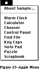 Figure 23–Apple Menu
The Apple menu also contains the “About xxx” menu item, where “xxx” is the name of the application. Choosing this item brings up a dialog box with the name and copyright information for the application, as well as any other information the application wants to display.
_______________________________________________________________________________
»The File Menu
The File menu lets the user perform certain simple filing operations without leaving the application and returning to the Finder. It also contains the commands for printing and for leaving the application. The standard File menu includes the commands shown in Figure 24. All of these commands are described below.
Figure 23–Apple Menu
The Apple menu also contains the “About xxx” menu item, where “xxx” is the name of the application. Choosing this item brings up a dialog box with the name and copyright information for the application, as well as any other information the application wants to display.
_______________________________________________________________________________
»The File Menu
The File menu lets the user perform certain simple filing operations without leaving the application and returning to the Finder. It also contains the commands for printing and for leaving the application. The standard File menu includes the commands shown in Figure 24. All of these commands are described below.
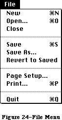 Figure 24–File Menu
»New
New opens a new, untitled document. The user names the document the first time it’s saved. The New command is disabled when the maximum number of documents allowed by the application is already open; however, an application that allows only one document to be open at a time may make an exception to this, as described below for Open.
»Open
Open opens an existing document. To select the document, the user is presented with a dialog box (Figure 25). This dialog box shows a list of all the documents, on the disk whose name is displayed, that can be handled by the current application. The user can scroll this list forward and backward. The dialog box also gives the user the chance to look at documents on another disk, or to eject a disk.
Figure 24–File Menu
»New
New opens a new, untitled document. The user names the document the first time it’s saved. The New command is disabled when the maximum number of documents allowed by the application is already open; however, an application that allows only one document to be open at a time may make an exception to this, as described below for Open.
»Open
Open opens an existing document. To select the document, the user is presented with a dialog box (Figure 25). This dialog box shows a list of all the documents, on the disk whose name is displayed, that can be handled by the current application. The user can scroll this list forward and backward. The dialog box also gives the user the chance to look at documents on another disk, or to eject a disk.
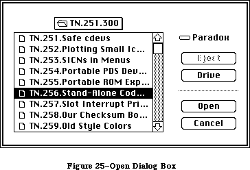 Figure 25–Open Dialog Box
Using the Open command, the user can only open a document that can be processed by the current application. Opening a document that can only be processed by a different application requires leaving the application and returning to the Finder.
The Open command is disabled when the maximum number of documents allowed by the application is already open. An application that allows only one document to be open at a time may make an exception to this, by first closing the open document before opening the new document. In this case, if the user has changed the open document since the last time it was saved, an alert box is presented as when an explicit Close command is given (see below); then the Open dialog box appears. Clicking Cancel in either the Close alert box or the Open dialog box cancels the entire operation.
»Close
Close closes the active window, which may be a document window, a desk accessory, or any other type of window. If it’s a document window and the user has changed the document since the last time it was saved, the command presents an alert box giving the user the opportunity to save the changes.
Clicking in the close box of a window is the same as choosing Close.
»Save
Save makes permanent any changes to the active document since the last time it was saved. It leaves the document open.
If the user chooses Save for a new document that hasn’t been named yet, the application presents the Save As dialog box (see below) to name the document, and then continues with the save. The active document remains active.
If there’s not enough room on the disk to save the document, the application asks if the user wants to save the document on another disk. If the answer is yes, the application goes through the Save As dialog to find out which disk.
»Save As
Save As saves a copy of the active document under a file name provided by the user.
If the document already has a name, Save As closes the old version of the document, creates a copy with the new name, and displays the copy in the window.
If the document is untitled, Save As saves the original document under the specified name. The active document remains active.
»Revert to Saved
Revert to Saved returns the active document to the state it was in the last time it was saved. Before doing so, it puts up an alert box to confirm that this is what the user wants.
»Page Setup
Page Setup lets the user specify printing parameters such as the paper size and printing orientation. These parameters remain with the document.
»Print
Print lets the user specify various parameters such as print quality and number of copies, and then prints the document. The parameters apply only to the current printing operation.
»Quit
Quit leaves the application and returns to the Finder. If any open documents have been changed since the last time they were saved, the application presents the same alert box as for Close, once for each document.
_______________________________________________________________________________
»The Edit Menu
The Edit menu contains the commands that delete, move, and copy objects, as well as commands such as Undo, Select All, and Show Clipboard. This section also discusses the Clipboard, which is controlled by the Edit menu commands. Text editing methods that don’t use menu commands are discussed under “Text Editing”.
If the application supports desk accessories, the order of commands in the Edit menu should be exactly as shown here. This is because, by default, the application passes the numbers, not the names, of the menu commands to the desk accessories. (For details, see the Desk Manager chapter) In particular, your application must provide an Undo command for the benefit of the desk accessories, even if it doesn’t support the command (in which case it can disable the command until a desk accessory is opened).
The standard order of commands in the Edit menu is shown in Figure 26.
Figure 25–Open Dialog Box
Using the Open command, the user can only open a document that can be processed by the current application. Opening a document that can only be processed by a different application requires leaving the application and returning to the Finder.
The Open command is disabled when the maximum number of documents allowed by the application is already open. An application that allows only one document to be open at a time may make an exception to this, by first closing the open document before opening the new document. In this case, if the user has changed the open document since the last time it was saved, an alert box is presented as when an explicit Close command is given (see below); then the Open dialog box appears. Clicking Cancel in either the Close alert box or the Open dialog box cancels the entire operation.
»Close
Close closes the active window, which may be a document window, a desk accessory, or any other type of window. If it’s a document window and the user has changed the document since the last time it was saved, the command presents an alert box giving the user the opportunity to save the changes.
Clicking in the close box of a window is the same as choosing Close.
»Save
Save makes permanent any changes to the active document since the last time it was saved. It leaves the document open.
If the user chooses Save for a new document that hasn’t been named yet, the application presents the Save As dialog box (see below) to name the document, and then continues with the save. The active document remains active.
If there’s not enough room on the disk to save the document, the application asks if the user wants to save the document on another disk. If the answer is yes, the application goes through the Save As dialog to find out which disk.
»Save As
Save As saves a copy of the active document under a file name provided by the user.
If the document already has a name, Save As closes the old version of the document, creates a copy with the new name, and displays the copy in the window.
If the document is untitled, Save As saves the original document under the specified name. The active document remains active.
»Revert to Saved
Revert to Saved returns the active document to the state it was in the last time it was saved. Before doing so, it puts up an alert box to confirm that this is what the user wants.
»Page Setup
Page Setup lets the user specify printing parameters such as the paper size and printing orientation. These parameters remain with the document.
»Print
Print lets the user specify various parameters such as print quality and number of copies, and then prints the document. The parameters apply only to the current printing operation.
»Quit
Quit leaves the application and returns to the Finder. If any open documents have been changed since the last time they were saved, the application presents the same alert box as for Close, once for each document.
_______________________________________________________________________________
»The Edit Menu
The Edit menu contains the commands that delete, move, and copy objects, as well as commands such as Undo, Select All, and Show Clipboard. This section also discusses the Clipboard, which is controlled by the Edit menu commands. Text editing methods that don’t use menu commands are discussed under “Text Editing”.
If the application supports desk accessories, the order of commands in the Edit menu should be exactly as shown here. This is because, by default, the application passes the numbers, not the names, of the menu commands to the desk accessories. (For details, see the Desk Manager chapter) In particular, your application must provide an Undo command for the benefit of the desk accessories, even if it doesn’t support the command (in which case it can disable the command until a desk accessory is opened).
The standard order of commands in the Edit menu is shown in Figure 26.
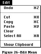 Figure 26–Edit Menu
»The Clipboard
The Clipboard holds whatever is cut or copied from a document. Its contents stay intact when the user changes documents, opens a desk accessory, or leaves the application. An application can show the contents of the Clipboard in a window, and can choose whether to have the Clipboard window open or closed when the application starts up.
The Clipboard window looks like a document window, with a close box but usually without scroll bars or a size box. The user can see its contents but cannot edit them. In most other ways the Clipboard window behaves just like any other window.
Every time the user performs a Cut or Copy on the current selection, a copy of the selection replaces the previous contents of the Clipboard. The previous contents are kept around in case the user chooses Undo.
There’s only one Clipboard, which is present for all applications that support Cut, Copy, and Paste. The user can see the Clipboard window by choosing Show Clipboard from the Edit menu. If the window is already showing, it’s hidden by choosing Hide Clipboard. (Show Clipboard and Hide Clipboard are a single toggled command.)
Because the contents of the Clipboard remain unchanged when applications begin and end, or when the user opens a desk accessory, the Clipboard can be used for transferring data among mutually compatible applications and desk accessories.
»Undo
Undo reverses the effect of the previous operation. Not all operations can be undone; the definition of an undoable operation is somewhat application-dependent. The general rule is that operations that change the contents of the document are undoable, and operations that don’t are not. Most menu items are undoable, and so are typing sequences.
A typing sequence is any sequence of characters typed from the keyboard or numeric keypad, including Backspace, Return, and Tab, but not including keyboard equivalents of commands.
Operations that aren’t undoable include selecting, scrolling, and splitting the window or changing its size or location. None of these operations interrupts a typing sequence. For example, if the user types a few characters and then scrolls the document, the Undo command still undoes the typing. Whenever the location affected by the Undo operation isn’t currently showing on the screen, the application should scroll the document so the user can see the effect of the Undo.
An application should also allow the user to undo any operations that are initiated directly on the screen, without a menu command. This includes operations controlled by setting dials, clicking check boxes, and so on, as well as drawing graphic objects with the mouse.
The actual wording of the Undo command as it appears in the Edit menu is “Undo xxx”, where xxx is the name of the last operation. If the last operation isn’t a menu command, use some suitable term after the word Undo. If the last operation can’t be undone, the command reads “Undo”, but is disabled.
If the last operation was Undo, the menu command is “Redo xxx”, where xxx is the operation that was undone. If this command is chosen, the Undo is undone.
»Cut
The user chooses Cut either to delete the current selection or to move it. A move is eventually completed by choosing Paste.
When the user chooses Cut, the application removes the current selection from the document and puts it in the Clipboard, replacing the Clipboard’s previous contents. The place where the selection used to be becomes the new selection; the visual implications of this vary among applications. For example, in text, the new selection is an insertion point, while in an array, it’s an empty but highlighted cell. If the user chooses Paste immediately after choosing Cut, the document should be just as it was before the cut.
»Copy
Copy is the first stage of a copy operation. Copy puts a copy of the selection in the Clipboard, but the selection also remains in the document. The user completes the copy operation by choosing Paste.
»Paste
Paste is the last stage of a move or copy operation. It pastes the contents of the Clipboard into the document, replacing the current selection. The user can choose Paste several times in a row to paste multiple copies. After a paste, the new selection is the object that was pasted, except in text, where it’s an insertion point immediately after the pasted text. The Clipboard remains unchanged.
»Clear
When the user chooses Clear, or presses the Clear key on the numeric keypad, the application removes the selection, but doesn’t put it in the Clipboard. The new selection is the same as it would be after a Cut.
»Select All
Select All selects every object in the document.
»Show Clipboard
Show Clipboard is a toggled command. When the Clipboard isn’t displayed, the command is “Show Clipboard”. If the user chooses this command, the Clipboard is displayed and the command changes to “Hide Clipboard”.
_______________________________________________________________________________
»Font-Related Menus
Three standard menus affect the appearance of text: Font, which determines the font of a text selection; FontSize, which determines the size of the characters; and Style, which determines aspects of its appearance such as boldface, italics, and so on.
A font is a set of typographical characters created with a consistent design. Things that relate characters in a font include the thickness of vertical and horizontal lines, the degree and position of curves and swirls, and the use of serifs. A font has the same general appearance, regardless of the size of the characters. Most Macintosh fonts are proportional rather than fixed-width; an application can’t make assumptions about exactly how many characters will fit in a given area when these fonts are used.
»Font Menu
The Font menu always lists the fonts that are currently available. Figure 27 shows a Font menu with some of the most common fonts.
Figure 26–Edit Menu
»The Clipboard
The Clipboard holds whatever is cut or copied from a document. Its contents stay intact when the user changes documents, opens a desk accessory, or leaves the application. An application can show the contents of the Clipboard in a window, and can choose whether to have the Clipboard window open or closed when the application starts up.
The Clipboard window looks like a document window, with a close box but usually without scroll bars or a size box. The user can see its contents but cannot edit them. In most other ways the Clipboard window behaves just like any other window.
Every time the user performs a Cut or Copy on the current selection, a copy of the selection replaces the previous contents of the Clipboard. The previous contents are kept around in case the user chooses Undo.
There’s only one Clipboard, which is present for all applications that support Cut, Copy, and Paste. The user can see the Clipboard window by choosing Show Clipboard from the Edit menu. If the window is already showing, it’s hidden by choosing Hide Clipboard. (Show Clipboard and Hide Clipboard are a single toggled command.)
Because the contents of the Clipboard remain unchanged when applications begin and end, or when the user opens a desk accessory, the Clipboard can be used for transferring data among mutually compatible applications and desk accessories.
»Undo
Undo reverses the effect of the previous operation. Not all operations can be undone; the definition of an undoable operation is somewhat application-dependent. The general rule is that operations that change the contents of the document are undoable, and operations that don’t are not. Most menu items are undoable, and so are typing sequences.
A typing sequence is any sequence of characters typed from the keyboard or numeric keypad, including Backspace, Return, and Tab, but not including keyboard equivalents of commands.
Operations that aren’t undoable include selecting, scrolling, and splitting the window or changing its size or location. None of these operations interrupts a typing sequence. For example, if the user types a few characters and then scrolls the document, the Undo command still undoes the typing. Whenever the location affected by the Undo operation isn’t currently showing on the screen, the application should scroll the document so the user can see the effect of the Undo.
An application should also allow the user to undo any operations that are initiated directly on the screen, without a menu command. This includes operations controlled by setting dials, clicking check boxes, and so on, as well as drawing graphic objects with the mouse.
The actual wording of the Undo command as it appears in the Edit menu is “Undo xxx”, where xxx is the name of the last operation. If the last operation isn’t a menu command, use some suitable term after the word Undo. If the last operation can’t be undone, the command reads “Undo”, but is disabled.
If the last operation was Undo, the menu command is “Redo xxx”, where xxx is the operation that was undone. If this command is chosen, the Undo is undone.
»Cut
The user chooses Cut either to delete the current selection or to move it. A move is eventually completed by choosing Paste.
When the user chooses Cut, the application removes the current selection from the document and puts it in the Clipboard, replacing the Clipboard’s previous contents. The place where the selection used to be becomes the new selection; the visual implications of this vary among applications. For example, in text, the new selection is an insertion point, while in an array, it’s an empty but highlighted cell. If the user chooses Paste immediately after choosing Cut, the document should be just as it was before the cut.
»Copy
Copy is the first stage of a copy operation. Copy puts a copy of the selection in the Clipboard, but the selection also remains in the document. The user completes the copy operation by choosing Paste.
»Paste
Paste is the last stage of a move or copy operation. It pastes the contents of the Clipboard into the document, replacing the current selection. The user can choose Paste several times in a row to paste multiple copies. After a paste, the new selection is the object that was pasted, except in text, where it’s an insertion point immediately after the pasted text. The Clipboard remains unchanged.
»Clear
When the user chooses Clear, or presses the Clear key on the numeric keypad, the application removes the selection, but doesn’t put it in the Clipboard. The new selection is the same as it would be after a Cut.
»Select All
Select All selects every object in the document.
»Show Clipboard
Show Clipboard is a toggled command. When the Clipboard isn’t displayed, the command is “Show Clipboard”. If the user chooses this command, the Clipboard is displayed and the command changes to “Hide Clipboard”.
_______________________________________________________________________________
»Font-Related Menus
Three standard menus affect the appearance of text: Font, which determines the font of a text selection; FontSize, which determines the size of the characters; and Style, which determines aspects of its appearance such as boldface, italics, and so on.
A font is a set of typographical characters created with a consistent design. Things that relate characters in a font include the thickness of vertical and horizontal lines, the degree and position of curves and swirls, and the use of serifs. A font has the same general appearance, regardless of the size of the characters. Most Macintosh fonts are proportional rather than fixed-width; an application can’t make assumptions about exactly how many characters will fit in a given area when these fonts are used.
»Font Menu
The Font menu always lists the fonts that are currently available. Figure 27 shows a Font menu with some of the most common fonts.
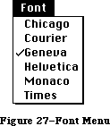 Figure 27–Font Menu
»FontSize Menu
Font sizes are measured in points; a point is about 1/72 of an inch. Each font is available in predefined sizes. The numbers of these sizes for each font are shown outlined in the FontSize menu. The font can also be scaled to other sizes, but it may not look as good. Figure 28 shows a FontSize menu with the standard font sizes.
Figure 27–Font Menu
»FontSize Menu
Font sizes are measured in points; a point is about 1/72 of an inch. Each font is available in predefined sizes. The numbers of these sizes for each font are shown outlined in the FontSize menu. The font can also be scaled to other sizes, but it may not look as good. Figure 28 shows a FontSize menu with the standard font sizes.
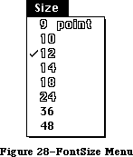 Figure 28–FontSize Menu
If there’s insufficient room in the menu bar for the word FontSize, it can be abbreviated to Size. If there’s insufficient room for both a Font menu and a Size menu, the sizes can be put at the end of the Font or Style menu.
»Style Menu
The commands in the standard Style menu are Plain Text, Bold, Italic, Underline, Outline, and Shadow. All the commands except Plain Text are accumulating attributes; the user can choose any combination. A command that’s in effect for the current selection is preceded by a check mark. Plain Text cancels all the other choices. Figure 29 shows these styles.
Figure 28–FontSize Menu
If there’s insufficient room in the menu bar for the word FontSize, it can be abbreviated to Size. If there’s insufficient room for both a Font menu and a Size menu, the sizes can be put at the end of the Font or Style menu.
»Style Menu
The commands in the standard Style menu are Plain Text, Bold, Italic, Underline, Outline, and Shadow. All the commands except Plain Text are accumulating attributes; the user can choose any combination. A command that’s in effect for the current selection is preceded by a check mark. Plain Text cancels all the other choices. Figure 29 shows these styles.
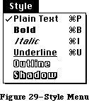 Figure 29–Style Menu
_______________________________________________________________________________
»Hierarchical Menus
Hierarchical menus are a logical extension of the current menu metaphor: another dimension is added to a menu, so that a menu item can be the title of a submenu. When the user drags the pointer through a hierarchical menu item, a submenu appears after a brief delay.
Hierarchical menu items have an indicator (a small black triangle pointing to the right, to indicate “more”) at the edge of the menu, as illustrated in Figure 30.
Figure 29–Style Menu
_______________________________________________________________________________
»Hierarchical Menus
Hierarchical menus are a logical extension of the current menu metaphor: another dimension is added to a menu, so that a menu item can be the title of a submenu. When the user drags the pointer through a hierarchical menu item, a submenu appears after a brief delay.
Hierarchical menu items have an indicator (a small black triangle pointing to the right, to indicate “more”) at the edge of the menu, as illustrated in Figure 30.
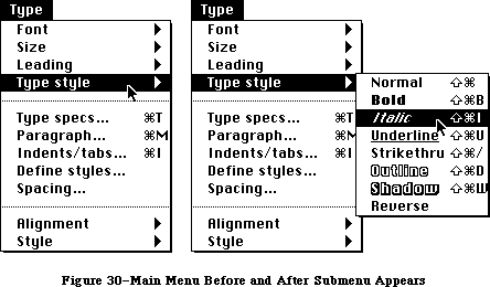 Figure 30–Main Menu Before and After Submenu Appears
One main menu can contain both standard menu items and submenus; both levels can have Command-key equivalents. (The submenu title can’t have a Command-key equivalent, of course, because it’s not a command. Key combinations aren’t used to pull down menus.)
Two delay values enable submenus to function smoothly, without jarring distractions to the user: The submenu delay is the length of time before a submenu appears as the user drags the pointer through a hierarchical menu item. It prevents flashing due to rapid appearance–disappearance of submenus. The drag delay allows the user to drag diagonally from the submenu title into the submenu, briefly crossing part of the main menu, without the submenu disappearing (which would ordinarily happen when the pointer was dragged into another main menu item). See Figure 31.
Figure 30–Main Menu Before and After Submenu Appears
One main menu can contain both standard menu items and submenus; both levels can have Command-key equivalents. (The submenu title can’t have a Command-key equivalent, of course, because it’s not a command. Key combinations aren’t used to pull down menus.)
Two delay values enable submenus to function smoothly, without jarring distractions to the user: The submenu delay is the length of time before a submenu appears as the user drags the pointer through a hierarchical menu item. It prevents flashing due to rapid appearance–disappearance of submenus. The drag delay allows the user to drag diagonally from the submenu title into the submenu, briefly crossing part of the main menu, without the submenu disappearing (which would ordinarily happen when the pointer was dragged into another main menu item). See Figure 31.
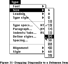 Figure 31–Dragging Diagonally to a Submenu Item
Other aspects of submenus—menu blink for example—behave exactly the same way as in standard menus.
The original Macintosh menus were designed so that the user could drag the mouse across the menu bar and immediately see all of the choices currently available. Although developers have found they need more menu space, and hierarchical menus were designed to meet that need, it’s important that this original capability be maintained as much as possible. To keep this essential simplicity and clarity, follow these guidelines:
• Hierarchical menus should be used only for lists of related items,
such as fonts or font sizes (in this case, the title of the submenu
clearly tells what the submenu contains).
• Only one level of hierarchical menu should be used, although the
capability for more is provided. This one extra layer of menus
potentially increases by an order of magnitude the number of menu
items that can be used; if you need more layers than that, your
application is probably more complex than most users can understand,
and you should rethink your design.
_______________________________________________________________________________
»Pop-Up Menus
A pop-up menu is one that isn’t in the menu bar, but appears somewhere else on the screen (usually in a dialog) when the user presses in a particular place, as shown in Figure 32.
Figure 31–Dragging Diagonally to a Submenu Item
Other aspects of submenus—menu blink for example—behave exactly the same way as in standard menus.
The original Macintosh menus were designed so that the user could drag the mouse across the menu bar and immediately see all of the choices currently available. Although developers have found they need more menu space, and hierarchical menus were designed to meet that need, it’s important that this original capability be maintained as much as possible. To keep this essential simplicity and clarity, follow these guidelines:
• Hierarchical menus should be used only for lists of related items,
such as fonts or font sizes (in this case, the title of the submenu
clearly tells what the submenu contains).
• Only one level of hierarchical menu should be used, although the
capability for more is provided. This one extra layer of menus
potentially increases by an order of magnitude the number of menu
items that can be used; if you need more layers than that, your
application is probably more complex than most users can understand,
and you should rethink your design.
_______________________________________________________________________________
»Pop-Up Menus
A pop-up menu is one that isn’t in the menu bar, but appears somewhere else on the screen (usually in a dialog) when the user presses in a particular place, as shown in Figure 32.
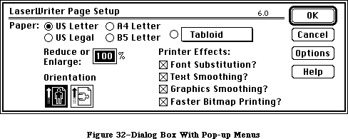 Figure 32–Dialog Box With Pop-Up Menus
Pop-up menus are used for setting values or choosing from lists of related items. The indication that there is a pop-up menu is a box with a one-pixel thick drop shadow, drawn around the current value. When the user presses this box, the pop-up menu appears, with the current value—checked and highlighted—under the pointer, as shown in Figure 33. If the menu has a title, the title is highlighted while the menu is visible.
Figure 32–Dialog Box With Pop-Up Menus
Pop-up menus are used for setting values or choosing from lists of related items. The indication that there is a pop-up menu is a box with a one-pixel thick drop shadow, drawn around the current value. When the user presses this box, the pop-up menu appears, with the current value—checked and highlighted—under the pointer, as shown in Figure 33. If the menu has a title, the title is highlighted while the menu is visible.
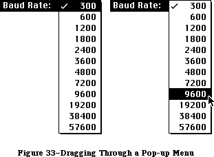 Figure 33–Dragging Through a Pop-up Menu
The pop-up menu acts like other menus: the user can move around in it and choose another item, which then appears in the box, or can move outside it to leave the current value active. If a pop-up menu reaches the top or bottom of the screen, it scrolls like other menus.
When designing an application that uses pop-up menus, keep in mind the following points:
• Pop-up menus should only be used for lists of values or related items
(much like hierarchical menus); they should not be used for commands.
• You must draw the shadowed box indicating that there is a pop-up menu,
so the user knows that it’s there—pop-up menus should never be invisible.
• While the menu is showing, its title should be inverted. If several
pop-up menus are near each other, this lessens ambiguity about which
one is being used.
• The current value should always appear under the pointer when the
menu pops up, so that simply clicking the box doesn’t change the item.
• Hierarchical pop-up menus should not be used.
Always consider whether a pop-up menu is the simplest thing to use in each case. For example, rather than have a pop-up menu choose all paper sizes, icons could represent commonly used sizes, with a pop-up menu for non-standard sizes.
_______________________________________________________________________________
»Scrolling Menu Indicator
Scrolling menus were introduced with the Macintosh Plus and Macintosh 512K Enhanced, but this feature was invisible. When there were more than eighteen items in a menu (which can happen with fonts on a hard disk), the menu scrolled to show more items as the user moved the pointer past the last item; but users didn’t know whether there were any more items in a menu unless they happened to drag past the bottom of it. The scrolling menu feature is now made visible by an indicator (similar to the hierarchical menu indicator), which appears at the bottom of the menu when there are more items, as shown in Figure 34.
Figure 33–Dragging Through a Pop-up Menu
The pop-up menu acts like other menus: the user can move around in it and choose another item, which then appears in the box, or can move outside it to leave the current value active. If a pop-up menu reaches the top or bottom of the screen, it scrolls like other menus.
When designing an application that uses pop-up menus, keep in mind the following points:
• Pop-up menus should only be used for lists of values or related items
(much like hierarchical menus); they should not be used for commands.
• You must draw the shadowed box indicating that there is a pop-up menu,
so the user knows that it’s there—pop-up menus should never be invisible.
• While the menu is showing, its title should be inverted. If several
pop-up menus are near each other, this lessens ambiguity about which
one is being used.
• The current value should always appear under the pointer when the
menu pops up, so that simply clicking the box doesn’t change the item.
• Hierarchical pop-up menus should not be used.
Always consider whether a pop-up menu is the simplest thing to use in each case. For example, rather than have a pop-up menu choose all paper sizes, icons could represent commonly used sizes, with a pop-up menu for non-standard sizes.
_______________________________________________________________________________
»Scrolling Menu Indicator
Scrolling menus were introduced with the Macintosh Plus and Macintosh 512K Enhanced, but this feature was invisible. When there were more than eighteen items in a menu (which can happen with fonts on a hard disk), the menu scrolled to show more items as the user moved the pointer past the last item; but users didn’t know whether there were any more items in a menu unless they happened to drag past the bottom of it. The scrolling menu feature is now made visible by an indicator (similar to the hierarchical menu indicator), which appears at the bottom of the menu when there are more items, as shown in Figure 34.
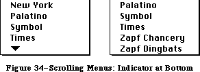 Figure 34–Scrolling Menus: Indicator at Bottom
The indicator area itself doesn’t highlight, but the menu scrolls as the user drags over it. When the last item is shown, the indicator disappears.
As soon as the menu starts scrolling, another indicator appears at the top of the menu to show that some items are now hidden in that direction (see
Figure 35).
Figure 34–Scrolling Menus: Indicator at Bottom
The indicator area itself doesn’t highlight, but the menu scrolls as the user drags over it. When the last item is shown, the indicator disappears.
As soon as the menu starts scrolling, another indicator appears at the top of the menu to show that some items are now hidden in that direction (see
Figure 35).
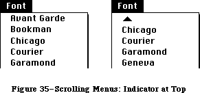 Figure 35–Scrolling Menus: Indicator at Top
If the user drags back up to the top, the menu scrolls back down in the same manner. If the user releases the mouse button or selects another menu, and then selects the menu again, it appears in its original position, with the hidden items and the indicator at the bottom.
_______________________________________________________________________________
»TEXT EDITING
_______________________________________________________________________________
In addition to the operations described under “The Edit Menu” above, there are other ways to edit text that don’t use menu items.
_______________________________________________________________________________
»Inserting Text
To insert text, the user selects an insertion point by clicking where the text is to go, and then starts typing it. As the user types, the application continually moves the insertion point to the right of each new character.
Applications with multiline text blocks should support word wraparound; that is, no word should be broken between lines. The definition of a word is given under “Selecting Words” above.
_______________________________________________________________________________
»Backspace
When the user presses the Backspace key, one of two things happens:
• If the current selection is one or more characters, it’s deleted.
• If the current selection is an insertion point, the previous
character is deleted.
In either case, the insertion point replaces the deleted characters in the document. The deleted characters don’t go into the Clipboard, but the deletion can be undone by immediately choosing Undo.
_______________________________________________________________________________
»Replacing Text
If the user starts typing when the selection is one or more characters, the characters that are typed replace the selection. The deleted characters don’t go into the Clipboard, but the replacement can be undone by immediately choosing Undo.
_______________________________________________________________________________
»Intelligent Cut and Paste
An application that lets the user select a word by double-clicking should also see to it that the user doesn’t regret using this feature. The only way to do this is by providing “intelligent” cut and paste.
To understand why this feature is necessary, consider the following sequence of events in an application that doesn’t provide it:
1. A sentence in the user’s document reads:
Returns are only accepted if the merchandise is damaged.
The user wants to change this to:
Returns are accepted only if the merchandise is damaged.
2. The user selects the word “only” by double-clicking. The letters are
highlighted, but not either of the adjacent spaces.
3. The user chooses Cut, clicks just before the word “if”, and chooses Paste.
4. The sentence now reads:
Returns are accepted onlyif the merchandise is damaged.
To correct the sentence, the user has to remove a space between “are”
and “accepted”, and add one between “only” and “if”. At this point he
or she may be wondering why the Macintosh is supposed to be easier to
use than other computers.
If an application supports intelligent cut and paste, the rules to follow are:
• If the user selects a word or a range of words, highlight the selection,
but not any adjacent spaces.
• When the user chooses Cut, if the character to the left of the selection
is a space, discard it. Otherwise, if the character to the right of the
selection is a space, discard it.
• When the user chooses Paste, if the character to the left or right of the
current selection is part of a word, insert a space before pasting.
If the left or right end of a text selection is a word, follow these rules at that end, regardless of whether there’s a word at the other end.
This feature makes more sense if the application supports the full definition of a word (as detailed above under “Selecting Words”), rather than the definition of a word as anything between two spaces.
These rules apply to any selection that’s one or more whole words, whether it was chosen with a double click or as a range selection.
Figure 36 shows some examples of intelligent cut and paste.
Figure 35–Scrolling Menus: Indicator at Top
If the user drags back up to the top, the menu scrolls back down in the same manner. If the user releases the mouse button or selects another menu, and then selects the menu again, it appears in its original position, with the hidden items and the indicator at the bottom.
_______________________________________________________________________________
»TEXT EDITING
_______________________________________________________________________________
In addition to the operations described under “The Edit Menu” above, there are other ways to edit text that don’t use menu items.
_______________________________________________________________________________
»Inserting Text
To insert text, the user selects an insertion point by clicking where the text is to go, and then starts typing it. As the user types, the application continually moves the insertion point to the right of each new character.
Applications with multiline text blocks should support word wraparound; that is, no word should be broken between lines. The definition of a word is given under “Selecting Words” above.
_______________________________________________________________________________
»Backspace
When the user presses the Backspace key, one of two things happens:
• If the current selection is one or more characters, it’s deleted.
• If the current selection is an insertion point, the previous
character is deleted.
In either case, the insertion point replaces the deleted characters in the document. The deleted characters don’t go into the Clipboard, but the deletion can be undone by immediately choosing Undo.
_______________________________________________________________________________
»Replacing Text
If the user starts typing when the selection is one or more characters, the characters that are typed replace the selection. The deleted characters don’t go into the Clipboard, but the replacement can be undone by immediately choosing Undo.
_______________________________________________________________________________
»Intelligent Cut and Paste
An application that lets the user select a word by double-clicking should also see to it that the user doesn’t regret using this feature. The only way to do this is by providing “intelligent” cut and paste.
To understand why this feature is necessary, consider the following sequence of events in an application that doesn’t provide it:
1. A sentence in the user’s document reads:
Returns are only accepted if the merchandise is damaged.
The user wants to change this to:
Returns are accepted only if the merchandise is damaged.
2. The user selects the word “only” by double-clicking. The letters are
highlighted, but not either of the adjacent spaces.
3. The user chooses Cut, clicks just before the word “if”, and chooses Paste.
4. The sentence now reads:
Returns are accepted onlyif the merchandise is damaged.
To correct the sentence, the user has to remove a space between “are”
and “accepted”, and add one between “only” and “if”. At this point he
or she may be wondering why the Macintosh is supposed to be easier to
use than other computers.
If an application supports intelligent cut and paste, the rules to follow are:
• If the user selects a word or a range of words, highlight the selection,
but not any adjacent spaces.
• When the user chooses Cut, if the character to the left of the selection
is a space, discard it. Otherwise, if the character to the right of the
selection is a space, discard it.
• When the user chooses Paste, if the character to the left or right of the
current selection is part of a word, insert a space before pasting.
If the left or right end of a text selection is a word, follow these rules at that end, regardless of whether there’s a word at the other end.
This feature makes more sense if the application supports the full definition of a word (as detailed above under “Selecting Words”), rather than the definition of a word as anything between two spaces.
These rules apply to any selection that’s one or more whole words, whether it was chosen with a double click or as a range selection.
Figure 36 shows some examples of intelligent cut and paste.
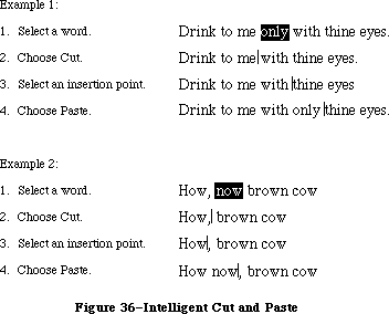 Figure 36–Intelligent Cut and Paste
_______________________________________________________________________________
»Editing Fields
If an application isn’t primarily a text application, but does use text in fields (such as in a dialog box), it may not be able to provide the full text editing capabilities described so far. It’s important, however, that whatever editing capabilities the application provides under these circumstances be upward-compatible with the full text editing capabilities. The following list shows the capabilities that can be provided, from the minimal to the most sophisticated:
• The user can select the whole field and type in a new value.
• The user can backspace.
• The user can select a substring of the field and replace it.
• The user can select a word by double-clicking.
• The user can choose Undo, Cut, Copy, Paste, and Clear, as described
above under “The Edit Menu”. In the most sophisticated version, the
application implements intelligent cut and paste.
An application should also perform appropriate edit checks. For example, if the only legitimate value for a field is a string of digits, the application might issue an alert if the user typed any nondigits. Alternatively, the application could wait until the user is through typing before checking the validity of the field’s contents. In this case, the appropriate time to check the field is when the user clicks anywhere other than within the field.
_______________________________________________________________________________
»DIALOGS AND ALERTS
_______________________________________________________________________________
The “select-then-choose” paradigm is sufficient whenever operations are simple and act on only one object. But occasionally a command will require more than one object, or will need additional parameters before it can be executed. And sometimes a command won’t be able to carry out its normal function, or will be unsure of the user’s real intent. For these special circumstances the Macintosh user interface includes two additional features:
• dialogs, to allow the user to provide additional information before
a command is executed
• alerts, to notify the user whenever an unusual situation occurs
Since both of these features lean heavily on controls, controls are described in this section, even though controls are also used in other places.
_______________________________________________________________________________
»Controls
Friendly systems act by direct cause-and-effect; they do what they’re told. Performing actions on a system in an indirect fashion reduces the sense of direct manipulation. To give Macintosh users the feeling that they’re in control of their machines, many of an application’s features are implemented with controls: graphic objects that, when manipulated with the mouse, cause instant action with visible results. Controls can also change settings to modify future actions.
There are four main types of controls: buttons, check boxes, radio buttons, and dials (see Figure 37). You can also design your own controls, such as a ruler on which tabs can be set.
Figure 36–Intelligent Cut and Paste
_______________________________________________________________________________
»Editing Fields
If an application isn’t primarily a text application, but does use text in fields (such as in a dialog box), it may not be able to provide the full text editing capabilities described so far. It’s important, however, that whatever editing capabilities the application provides under these circumstances be upward-compatible with the full text editing capabilities. The following list shows the capabilities that can be provided, from the minimal to the most sophisticated:
• The user can select the whole field and type in a new value.
• The user can backspace.
• The user can select a substring of the field and replace it.
• The user can select a word by double-clicking.
• The user can choose Undo, Cut, Copy, Paste, and Clear, as described
above under “The Edit Menu”. In the most sophisticated version, the
application implements intelligent cut and paste.
An application should also perform appropriate edit checks. For example, if the only legitimate value for a field is a string of digits, the application might issue an alert if the user typed any nondigits. Alternatively, the application could wait until the user is through typing before checking the validity of the field’s contents. In this case, the appropriate time to check the field is when the user clicks anywhere other than within the field.
_______________________________________________________________________________
»DIALOGS AND ALERTS
_______________________________________________________________________________
The “select-then-choose” paradigm is sufficient whenever operations are simple and act on only one object. But occasionally a command will require more than one object, or will need additional parameters before it can be executed. And sometimes a command won’t be able to carry out its normal function, or will be unsure of the user’s real intent. For these special circumstances the Macintosh user interface includes two additional features:
• dialogs, to allow the user to provide additional information before
a command is executed
• alerts, to notify the user whenever an unusual situation occurs
Since both of these features lean heavily on controls, controls are described in this section, even though controls are also used in other places.
_______________________________________________________________________________
»Controls
Friendly systems act by direct cause-and-effect; they do what they’re told. Performing actions on a system in an indirect fashion reduces the sense of direct manipulation. To give Macintosh users the feeling that they’re in control of their machines, many of an application’s features are implemented with controls: graphic objects that, when manipulated with the mouse, cause instant action with visible results. Controls can also change settings to modify future actions.
There are four main types of controls: buttons, check boxes, radio buttons, and dials (see Figure 37). You can also design your own controls, such as a ruler on which tabs can be set.
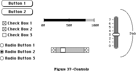 Figure 37–Controls
»Buttons
Buttons are small objects labeled with text. Clicking or pressing a button performs the action described by the button’s label.
Buttons usually perform instantaneous actions, such as completing operations defined by a dialog box or acknowledging error messages. They can also perform continuous actions, in which case the effect of pressing on the button would be the same as the effect of clicking it repeatedly.
Two particular buttons, OK and Cancel, are especially important in dialogs and alerts; they’re discussed under those headings below.
»Check Boxes and Radio Buttons
Whereas buttons perform instantaneous or continuous actions, check boxes and radio buttons let the user choose among alternative values for a parameter.
Check boxes act like toggle switches; they’re used to indicate the state of a parameter that must be either off or on. The parameter is on if the box is checked, otherwise it’s off. The check boxes appearing together in a given context are independent of each other; any number of them can be off or on.
Radio buttons typically occur in groups; they’re round and are filled in with a black circle when on. They’re called radio buttons because they act like the buttons on a car radio. At any given time, exactly one button in the group is on. Clicking one button in a group turns off the button that’s currently on.
Both check boxes and radio buttons are accompanied by text that identifies what each button does.
»Dials
Dials display the value, magnitude, or position of something in the application or system, and optionally allow the user to alter that value. Dials are predominantly analog devices, displaying their values graphically and allowing the user to change the value by dragging an indicator; dials may also have a digital display.
The most common example of a dial is the scroll bar. The indicator of the scroll bar is the scroll box; it represents the position of the window over the length of the document. The user can drag the scroll box to change that position. (See “Scroll Bars” above.)
_______________________________________________________________________________
»»Dialogs
Commands in menus normally act on only one object. If a command needs more information before it can be performed, it presents a dialog box to gather the additional information from the user. The user can tell which commands bring up dialog boxes because they’re followed by an ellipsis (...) in the menu.
A dialog box is a rectangle that may contain text, controls, and icons. There should be some text in the box that indicates which command brought up the dialog box.
The user sets controls and text fields in the dialog box to provide the needed information. When the application puts up the dialog box, it should set the controls to some default setting and fill in the text fields with default values, if possible. One of the text fields (the “first” field) should be highlighted, so that the user can change its value just by typing in the new value. If all the text fields are blank, there should be an insertion point in the first field.
Editing text fields in a dialog box should conform to the guidelines detailed above under “Text Editing”.
When the user is through editing an item:
• Pressing Tab accepts the changes made to the item, and selects the
next item in sequence.
• Clicking in another item accepts the changes made to the previous
item and selects the newly clicked item.
Dialog boxes are either modal or modeless, as described below.
»Modal Dialog Boxes
A modal dialog box is one that the user must explicitly dismiss before doing anything else, such as making a selection outside the dialog box or choosing a command. Figure 38 shows a modal dialog box.
Figure 37–Controls
»Buttons
Buttons are small objects labeled with text. Clicking or pressing a button performs the action described by the button’s label.
Buttons usually perform instantaneous actions, such as completing operations defined by a dialog box or acknowledging error messages. They can also perform continuous actions, in which case the effect of pressing on the button would be the same as the effect of clicking it repeatedly.
Two particular buttons, OK and Cancel, are especially important in dialogs and alerts; they’re discussed under those headings below.
»Check Boxes and Radio Buttons
Whereas buttons perform instantaneous or continuous actions, check boxes and radio buttons let the user choose among alternative values for a parameter.
Check boxes act like toggle switches; they’re used to indicate the state of a parameter that must be either off or on. The parameter is on if the box is checked, otherwise it’s off. The check boxes appearing together in a given context are independent of each other; any number of them can be off or on.
Radio buttons typically occur in groups; they’re round and are filled in with a black circle when on. They’re called radio buttons because they act like the buttons on a car radio. At any given time, exactly one button in the group is on. Clicking one button in a group turns off the button that’s currently on.
Both check boxes and radio buttons are accompanied by text that identifies what each button does.
»Dials
Dials display the value, magnitude, or position of something in the application or system, and optionally allow the user to alter that value. Dials are predominantly analog devices, displaying their values graphically and allowing the user to change the value by dragging an indicator; dials may also have a digital display.
The most common example of a dial is the scroll bar. The indicator of the scroll bar is the scroll box; it represents the position of the window over the length of the document. The user can drag the scroll box to change that position. (See “Scroll Bars” above.)
_______________________________________________________________________________
»»Dialogs
Commands in menus normally act on only one object. If a command needs more information before it can be performed, it presents a dialog box to gather the additional information from the user. The user can tell which commands bring up dialog boxes because they’re followed by an ellipsis (...) in the menu.
A dialog box is a rectangle that may contain text, controls, and icons. There should be some text in the box that indicates which command brought up the dialog box.
The user sets controls and text fields in the dialog box to provide the needed information. When the application puts up the dialog box, it should set the controls to some default setting and fill in the text fields with default values, if possible. One of the text fields (the “first” field) should be highlighted, so that the user can change its value just by typing in the new value. If all the text fields are blank, there should be an insertion point in the first field.
Editing text fields in a dialog box should conform to the guidelines detailed above under “Text Editing”.
When the user is through editing an item:
• Pressing Tab accepts the changes made to the item, and selects the
next item in sequence.
• Clicking in another item accepts the changes made to the previous
item and selects the newly clicked item.
Dialog boxes are either modal or modeless, as described below.
»Modal Dialog Boxes
A modal dialog box is one that the user must explicitly dismiss before doing anything else, such as making a selection outside the dialog box or choosing a command. Figure 38 shows a modal dialog box.
 Figure 38–A Modal Dialog Box
Because it restricts the user’s freedom of action, this type of dialog box should be used sparingly. In particular, the user can’t choose a menu item while a modal dialog box is up, and therefore can only do the simplest kinds of text editing. For these reasons, the main use of a modal dialog box is when
it’s important for the user to complete an operation before doing anything else.
A modal dialog box usually has at least two buttons: OK and Cancel. OK dismisses the dialog box and performs the original command according to the information provided; it can be given a more descriptive name than “OK”. Cancel dismisses the dialog box and cancels the original command; it should always be called “Cancel”.
A dialog box can have other kinds of buttons as well; these may or may not dismiss the dialog box. One of the buttons in the dialog box may be outlined boldly. The outlined button is the default button; if no button is outlined, then the OK button is the default button. The default button should be the safest button in the current situation. Pressing the Return or Enter key has the same effect as clicking the default button. If there’s no default button, Return and Enter have no effect.
A special type of modal dialog box is one with no buttons. This type of box just informs the user of a situation without eliciting any response. Usually, it would describe the progress of an ongoing operation. Since it has no buttons, the user has no way to dismiss it. Therefore, the application must leave it up long enough for the user to read it before taking it down.
»Modeless Dialog Boxes
A modeless dialog box allows the user to perform other operations without dismissing the dialog box. Figure 39 shows a modeless dialog box.
A modeless dialog box is dismissed by clicking in the close box or by choosing Close when the dialog is active. The dialog box is also dismissed implicitly when the user chooses Quit. It’s usually a good idea for the application to remember the contents of the dialog box after it’s dismissed, so that when it’s opened again, it can be restored exactly as it was.
Figure 38–A Modal Dialog Box
Because it restricts the user’s freedom of action, this type of dialog box should be used sparingly. In particular, the user can’t choose a menu item while a modal dialog box is up, and therefore can only do the simplest kinds of text editing. For these reasons, the main use of a modal dialog box is when
it’s important for the user to complete an operation before doing anything else.
A modal dialog box usually has at least two buttons: OK and Cancel. OK dismisses the dialog box and performs the original command according to the information provided; it can be given a more descriptive name than “OK”. Cancel dismisses the dialog box and cancels the original command; it should always be called “Cancel”.
A dialog box can have other kinds of buttons as well; these may or may not dismiss the dialog box. One of the buttons in the dialog box may be outlined boldly. The outlined button is the default button; if no button is outlined, then the OK button is the default button. The default button should be the safest button in the current situation. Pressing the Return or Enter key has the same effect as clicking the default button. If there’s no default button, Return and Enter have no effect.
A special type of modal dialog box is one with no buttons. This type of box just informs the user of a situation without eliciting any response. Usually, it would describe the progress of an ongoing operation. Since it has no buttons, the user has no way to dismiss it. Therefore, the application must leave it up long enough for the user to read it before taking it down.
»Modeless Dialog Boxes
A modeless dialog box allows the user to perform other operations without dismissing the dialog box. Figure 39 shows a modeless dialog box.
A modeless dialog box is dismissed by clicking in the close box or by choosing Close when the dialog is active. The dialog box is also dismissed implicitly when the user chooses Quit. It’s usually a good idea for the application to remember the contents of the dialog box after it’s dismissed, so that when it’s opened again, it can be restored exactly as it was.
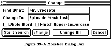 Figure 39–A Modeless Dialog Box
Controls work the same way in modeless dialog boxes as in modal dialog boxes, except that buttons never dismiss the dialog box. In this context, the OK button means “go ahead and perform the operation, but leave the dialog box up”, while Cancel usually terminates an ongoing operation.
A modeless dialog box can also have text fields; since the user can choose menu commands, the full range of editing capabilities can be made available.
»Standard Close Dialog
When a user chooses Close or Quit from the File menu, and the active document has been changed, the Close dialog box appears, asking “Save changes before closing?” A great deal of work can be lost if a user mistakenly clicks the “No” button instead of “Cancel”. This is especially important to MultiFinder users, who often move from one application to another and become less aware of subtle differences between applications. To avoid confusion, all applications should use the same standard Close dialog. As shown in Figure 40, dialogs can have multiple lines of text.
Figure 39–A Modeless Dialog Box
Controls work the same way in modeless dialog boxes as in modal dialog boxes, except that buttons never dismiss the dialog box. In this context, the OK button means “go ahead and perform the operation, but leave the dialog box up”, while Cancel usually terminates an ongoing operation.
A modeless dialog box can also have text fields; since the user can choose menu commands, the full range of editing capabilities can be made available.
»Standard Close Dialog
When a user chooses Close or Quit from the File menu, and the active document has been changed, the Close dialog box appears, asking “Save changes before closing?” A great deal of work can be lost if a user mistakenly clicks the “No” button instead of “Cancel”. This is especially important to MultiFinder users, who often move from one application to another and become less aware of subtle differences between applications. To avoid confusion, all applications should use the same standard Close dialog. As shown in Figure 40, dialogs can have multiple lines of text.
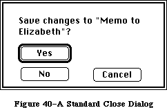 Figure 40–A Standard Close Dialog
»Close Box Specifications
“Yes” and “No”, the two direct responses to the question “Save changes before closing?” are placed together on the left side of the box. “Yes”, the default button, is boldly outlined. “Cancel”, which cancels the close command, is to the right, separate from “Yes” and “No”.
After the user selects Close from the File menu, the text of the question in the Close box is generally “Save changes before closing?” However, if the user sees this dialog after choosing “Quit”, the text would instead be “Save changes before quitting?” If the application supports multiple windows, the text could be “Save changes to [document name] before closing window?” The box should always look the same and appear in the same place on the screen.
The box itself is 120 pixels high by 238 pixels wide. Its standard location is
(100,120)(220,358) but other locations may be appropriate.
Here are the other coordinates for the standard close box (assuming standard location):
the text (12,20)(45,223)
the word “yes” (58,25)(76,99)
the word “no” (86,25)(104,99)
the word “cancel” (86,141)(104,215)
If you must devise a close box different from the one described here, maintain the general arrangement of the buttons and remember that the user’s safest choice should be the default button and that the most dangerous choice should be the most difficult to make happen.
_______________________________________________________________________________
»Alerts
Every user of every application is liable to do something that the application won’t understand or can’t cope with in a normal manner. Alerts give applications a way to respond to errors not only in a consistent manner, but in stages according to the severity of the error, the user’s level of expertise, and the particular history of the error. The two kinds of alerts are beeps and alert boxes.
Beeps are used for errors that are both minor and immediately obvious. For example, if the user tries to backspace past the left boundary of a text field, the application could choose to beep instead of putting up an alert box. A beep can also be part of a staged alert, as described below.
An alert box looks like a modal dialog box, except that it’s somewhat narrower and appears lower on the screen. An alert box is primarily a one way communication from the system to the user; the only way the user can respond is by clicking buttons. Therefore alert boxes might contain dials and buttons, but usually not text fields, radio buttons, or check boxes. Figure 41 shows a typical alert box.
Figure 40–A Standard Close Dialog
»Close Box Specifications
“Yes” and “No”, the two direct responses to the question “Save changes before closing?” are placed together on the left side of the box. “Yes”, the default button, is boldly outlined. “Cancel”, which cancels the close command, is to the right, separate from “Yes” and “No”.
After the user selects Close from the File menu, the text of the question in the Close box is generally “Save changes before closing?” However, if the user sees this dialog after choosing “Quit”, the text would instead be “Save changes before quitting?” If the application supports multiple windows, the text could be “Save changes to [document name] before closing window?” The box should always look the same and appear in the same place on the screen.
The box itself is 120 pixels high by 238 pixels wide. Its standard location is
(100,120)(220,358) but other locations may be appropriate.
Here are the other coordinates for the standard close box (assuming standard location):
the text (12,20)(45,223)
the word “yes” (58,25)(76,99)
the word “no” (86,25)(104,99)
the word “cancel” (86,141)(104,215)
If you must devise a close box different from the one described here, maintain the general arrangement of the buttons and remember that the user’s safest choice should be the default button and that the most dangerous choice should be the most difficult to make happen.
_______________________________________________________________________________
»Alerts
Every user of every application is liable to do something that the application won’t understand or can’t cope with in a normal manner. Alerts give applications a way to respond to errors not only in a consistent manner, but in stages according to the severity of the error, the user’s level of expertise, and the particular history of the error. The two kinds of alerts are beeps and alert boxes.
Beeps are used for errors that are both minor and immediately obvious. For example, if the user tries to backspace past the left boundary of a text field, the application could choose to beep instead of putting up an alert box. A beep can also be part of a staged alert, as described below.
An alert box looks like a modal dialog box, except that it’s somewhat narrower and appears lower on the screen. An alert box is primarily a one way communication from the system to the user; the only way the user can respond is by clicking buttons. Therefore alert boxes might contain dials and buttons, but usually not text fields, radio buttons, or check boxes. Figure 41 shows a typical alert box.
 Figure 41–An Alert Box
There are three types of alert boxes:
• Note: A minor mistake that wouldn’t have any disastrous consequences
if left as is.
• Caution: An operation that may or may not have undesirable results
if it’s allowed to continue. The user is given the choice whether or
not to continue.
• Stop: A serious problem or other situation that requires remedial
action by the user.
An application can define different responses for each of several stages of an alert, so that if the user persists in the same mistake, the application can issue increasingly more helpful (or sterner) messages. A typical sequence is for the first two occurrences of the mistake to result in a beep, and for subsequent occurrences to result in an alert box. This type of sequence is especially appropriate when the mistake is one that has a high probability of being accidental (for example, when the user chooses Cut when there’s no text selection).
How the buttons in an alert box are labeled depends on the nature of the box. If the box presents the user with a situation in which no alternative actions are available, the box has a single button that’s labeled OK. Clicking this button means “I’ve read the alert.” If the user is given alternatives, then typically the alert is phrased as a question that can be answered “yes” or “no”. In this case, buttons labeled Yes and No are appropriate, although some variation such as Save and Don’t Save is also acceptable. OK and Cancel can be used, as long as their meanings aren’t ambiguous.
The preferred (safest) button to use in the current situation is boldly outlined. This is the alert’s default button; its effect occurs if the user presses Return or Enter.
It’s important to phrase messages in alert boxes so that users aren’t left guessing the real meaning. Avoid computer jargon.
Use icons whenever possible. Graphics can better describe some error situations than words, and familiar icons help users distinguish their alternatives better. Icons should be internationally comprehensible; they shouldn’t contain any words, or any symbols that are unique to a particular country.
Generally, it’s better to be polite than abrupt, even if it means lengthening the message. The role of the alert box is to be helpful and make constructive suggestions, not to give orders. But its focus is to help the user solve the problem, not to give an interesting but academic description of the problem itself.
Under no circumstances should an alert message refer the user to external documentation for further clarification. It should provide an adequate description of the information needed by the user to take appropriate action.
The best way to make an alert message understandable is to think carefully through the error condition itself. Can the application handle this without an error? Is the error specific enough so that the user can fix the situation? What are the recommended solutions? Can the exact item causing the error be displayed in the alert message?
_______________________________________________________________________________
»COLOR
_______________________________________________________________________________
Apple’s goal in adding color to the desktop user interface is to add meaning, not just to color things so they “look good”. Color can be a valuable additional channel of information to the user, but must be used carefully; otherwise, it can have the opposite of the effect you were trying for, and can be overwhelming visually (or look game-like).
Color is ultimately the domain of the user, who should be able to modify or remove any coloring imposed by the application. Unless you are implementing a color application such as a paint or draw program, you should consider color only for the data, not the interface.
In order to successfully implement color in an application, you should understand some of the complex issues surrounding its use. Many major theories on the proper use of color are not complete or well defined. The way in which the human eye sees color is not fully understood, nor are color’s subjective effects.
_______________________________________________________________________________
»Standard Uses of Color
In traditional user interface design, color is used to associate or separate objects and information in the following ways:
• discriminate between different areas
• show which things are functionally related
• show relationships between things
• identify crucial features
_______________________________________________________________________________
»Color Coding
Different colors have standard associations in different cultures. “Meanings” of colors usually have nothing to do with the wavelength of the color, but are learned through conditioning within a particular culture. Some of the more universal meanings for colors are
• Red: stop, error, or failure. (For disk drives, red also means
disk access in progress; don’t remove the disk or turn it off.).
• Yellow: warning, caution, or delay.
• Green: go, ready, or power on.
• Warm versus cold: reds, oranges, and yellows are perceived as hot
or exciting colors; blues and greens are cool, calm colors.
Colors often have additional standard meanings within a particular discipline: in the financial world, red means loss and black means gain. To a mapmaker, green means wooded areas, blue means water, yellow means deserts. In an application for a specific field, you can take advantage of these meanings; in a general application, you should allow users to change the colors and to turn off any color-coding that you use as a default.
For attracting the user’s attention, orange and red are more effective than other colors, but usually connote “warning” or “danger”. (Be aware, though, that in some cases, attracting the eye might not be what you want to do; for example, if “dangerous” menu items are colored red, the user’s eye will be attracted to the red items, and the user might be more likely to select the items by mistake.)
Although the screen may be able to display 256 or more colors, the human eye can discriminate only around 128 pure hues. Furthermore, when colors are used to signify information, studies have shown that the mind can only effectively follow four to seven color assignments on a screen at once.
_______________________________________________________________________________
»General Principles of Color Design
Two principles should guide the design of your application: begin the design in black and white, and limit the use of color, especially in the application’s use of the standard interface.
»Design in Black and White
You should design your application first in black and white. Color should be supplementary, providing extra information for those users who have color. Color shouldn’t be the only thing that distinguishes two objects; there should always be other cues, such as shape, location, pattern, or sound. There are several reasons for this:
• Monitors: Most of your users won’t have color. The majority of Macintosh
computers that Apple ships are black and white, and will continue to be
so for some time.
• Printing: Currently, color printing is not very accurate, and even when
high-quality color printing becomes available, there is usually a
significant change in colors between media.
• Colorblindness: A significant percentage of the population is colorblind
to some degree. (In Europe and America, about 8% of males and 0.5% of
females have some sort of defective color vision.) The most common form
of colorblindness is a loss of ability to distinguish red and green from
gray. In another form, yellow, blue, and gray are indistinguishable.
• Lighting: Under dim lighting conditions, colors tend to wash out and
become difficult for the eye to distinguish—the differences between colors
must be greater, and the number of colors fewer, for them to be
discernable. You can’t know the conditions under which your application
may be used.
»Limit Color Use
In the standard interface part of applications (menus, window frames, etc.), color should be used mimimally or not at all; the Macintosh interface is very succesful in black and white. You want the user’s attention focused on the content of the application, rather than distracted by color in the menus or scroll bars. Availability of color in the content area of your application depends on the sort of application:
• Graphics applications, which are concerned with the image itself,
should take full advantage of the color capabilities of Color QuickDraw,
letting the user choose from and modify as many colors as are available.
• Other applications, which deal with the organization of information,
should limit the use of color much more than this. Color-coding should
be allowed or provided to make the information clearer. Providing the
user with a small initial selection of distinct colors—four to seven at
most—with the capability of changing those or adding more, is the best
solution to this.
_______________________________________________________________________________
»Contrast and Discrimination
Color adds another dimension to the array of possible contrasts, and care must be given to maintain good readability and discernment.
»Colors on Grays
Colors look best against a background of neutral gray, like the desktop. Colors within your application will stand out more if the background and surrounding areas (such as the window frame and menus) are black and white or gray.
»Colored Text
Reading and legibility studies in the print (paper) world show that colored text is harder to read than black text on a white background. This also appears to be true in the limited studies that have been done in the computer domain, although almost all these studies have looked at colors on a black background, not the white background used in the Macintosh.
»Beware of Blue
The most illegible color is light blue, which should be avoided for text,
thin lines, and small shapes. Adjacent colors that differ only in the amount of blue should also be avoided. However, for things that you want to go unnoticed, like grid lines, blue is the perfect color (think of graph paper or lined paper).
»Small Objects
People cannot easily discriminate between small areas of color—to be able to tell what color something is, you have to have enough of it. Changes in the color of small objects must be obvious, not subtle.
_______________________________________________________________________________
»Specific Recommendations
Remember that color should never be the only thing that distinguishes objects. Other cues such as shape, location, pattern, or sound, should always be used in addition to color, for the reasons discussed above.
»Color the Black Bits Only
Generally, all interface elements should maintain a white background, using color to replace black pixels as appropriate. Maintaining the white background and only coloring what is already black (if something needs to be colored at all) helps to maintain the clarity and the “look and feel” of the Macintosh interface.
»Leave Outlines Black
Outlines of menus, windows, and alert and dialog boxes should remain in black. Edges formed by color differences alone are hard for the eye to focus on, and these objects may appear against a colored desktop or window.
»Highlighting and Selection
Most things—menu items, icons, buttons, and so forth—should highlight by reversing the white background with the colored or black bits when selected.
(For example, if the item is red on a white background, it should highlight to white on a red background.) However, if multiple colors of text appear together, Color TextEdit allows the user to set the highlighting bar color to something other than black to highlight the text better. The default for the bar color is always black.
»Menus
In general, the only use of color in menus should be in menus used to choose colors. However, color could also be useful for directing the user’s choices in training and tutorial materials: one color can lead the user through a lesson.
»Windows
Since the focus of attention is on the content region of the window, color should be used only in that area. Using color in the scroll bars or title bar can simply distract the user. (A possible exception would be coloring part of a window to match the color of the icon from which it came.)
»Dialogs and Alerts
Except for dialog boxes used to select colors, there’s no reason to color dialog boxes; they should be designed and laid out clearly enough that color isn’t necessary to separate different sections or items. Alert boxes must be as clear as possible; color can add confusion instead of clarity. For example, if you tried to make things clearer by using red to mean “dangerous” and green to mean “safe” in the Erase Disk alert, the OK button (“go”) would be red and the Cancel (“stop”) button would be green. Don’t do this.
»Pointers
Most of the time, when the pointer is being used for selecting and pointing, it should remain black—color might not be visible over potentially different colored backgrounds, and wouldn’t give the user any extra information. However, when the user is drawing or typing in color, the drawing or text-insertion pointer should appear in the color that is being used. Except for multicolored paintbrush pointers, the pointer shouldn’t contain more than one color at once—it’s hard for the eye to discriminate small areas of color.
_______________________________________________________________________________
»SOUND
_______________________________________________________________________________
The high-quality sound capabilities of the Macintosh let sound be integrated into the human interface to give users additional information. This section refers to sound as a part of the interface in standard applications, not to the way sound is used in an application that uses the sound itself as data, such as a music composition application.
_______________________________________________________________________________
»When to Use Sound
There are two general ways that sound can be used in the interface:
• It can be integrated throughout the standard interface to help make
the user aware of the state of the computer or application.
• It can be used to alert the user when something happens unexpectedly,
in the background, or when the user is not looking at the screen.
In general, when you put an indicator on the screen to tell the user something—for example, to tell the user that mail has come in, or to show a particular state—it’s also appropriate to use a sound.
»Getting Attention
If the computer is doing something time-consuming, and the user may have turned away from the screen, sound is a good way to let the user know that the process is finished, or it needs attention. (There should also be an indication on the screen, of course.)
»Alerts
Common alerts can use sounds other than the SysBeep for their first stage or two before bringing up an alert box. For example, when users try to paste when there’s nothing in the Clipboard, or try to backspace past the top of a field, different sounds could alert them.
»Modes
If your application has different states or modes, each one can have a particular sound when the user enters or leaves. This can emphasize the current mode, and prevent confusion.
_______________________________________________________________________________
»General Guidelines
Although the use of sound in the Desktop Interface hasn’t been investigated thoroughly, these are some general guidelines to keep in mind.
»Don’t Go Overboard
Be thoughtful about where and how you use sound in an application. If you overuse sound, it won’t add any meaning to the interface, and will probably be annoying.
»Redundancy
Sound should never be the only indication that something has happened; there should always be a visible indication on the screen, too, especially when the user needs to know what happened. The user may have all sound turned off, may have been out of hearing range of the computer, or may have a hearing impairment.
»Natural and Unobtrusive
Most sounds can be quite subtle and still getting their meaning across. Loud, harsh sounds can be offensive or intimidating. You should always use the sound yourself and test it on users for a significant period of time (a week or two, not twenty minutes) before including it in your application—if you turn it off after a day, chances are other people will, too. You should also avoid using tunes or jingles—more than two or three notes of a tune may become annoying or sound silly if heard very often.
»Significant Differences
Users can learn to recognize and discriminate between sounds, but different sounds should be significantly different. Nonmusicians often can’t tell the difference between two similar notes or chords, especially when the sounds are separated by a space of time.
»User Control
The user can change the volume of sounds, or turn sound off altogether, using the Control Panel desk accessory. Never override this capability.
»Resources
Always store sounds as resources, so users can change sounds and add additional sounds.
_______________________________________________________________________________
»USER TESTING
_______________________________________________________________________________
The primary test of the user interface is its success with users: can people understand what to do and can they accomplish the task at hand easily and efficiently? The best way to answer these questions is to put them to the users.
_______________________________________________________________________________
»Build User Testing Into the Design Process
Users should be involved early in the design process so that changes in the basic concept of the product can still be made, if necessary. Although there’s a natural tendency to wait for a good working prototype before showing the product to anyone, this is too late for the user to have a significant impact on design. In the absence of working code, you can show test subjects alternate designs on paper or storyboards. There are lots of ways that early concepts can be tested on potential users of a product. Then, as the design progresses, the testing can become more refined and can focus on screen designs and specific features of the interface.
_______________________________________________________________________________
»Test Subjects
There is no such thing as a “typical user”. You should, however, be able to identify some people who are familiar with the task your application supports but are unfamiliar with the specific technology you are using. These “naive experts” make good subjects because they don’t have to be taught what the application is for, they are probably already motivated to use it, and they know what is required to accomplish the task.
You don’t need to test a lot of people. The best procedure for formative testing (testing during the design process) is to collect data from a few subjects, analyze the results and apply them as appropriate. Then, identify new questions that arise and questions that still need answers, and begin all over again—it is an iterative process.
_______________________________________________________________________________
»Procedures
Planning and carrying out a true experimental test takes time and expert training. But many of the questions you may have about your design do not require such a rigid approach. Furthermore, the computer and application already provide a controlled setting from which objective data can be gathered quite reliably. The major requirements are
• to make objective observations
• to record the data during the user-product interaction
Objective observations include measures of time, frequencies, error rates, and so forth. The simple and direct recording of what the person does and says while working is also an objective observation, however, and is often very useful to designers. Test subjects can be encouraged to talk as they work, telling what they are doing, trying to do, expect to happen, etc. This record of a person’s thinking aloud is called a protocol by researchers in the fields of cognition and problem-solving, and is a major source of their data.
The process of testing described here involves the application designer and the test subjects in a regular cycle of feedback and revision. Although the test procedures themselves may be informal, user-testing of the concepts and features of the interface becomes a regular, integral part of the design process.
_______________________________________________________________________________
»DO’S AND DON’TS OF A FRIENDLY USER INTERFACE
_______________________________________________________________________________
Do:
• Let the user have as much control as possible over the appearance
of objects on the screen—their arrangement, size, and visibility.
• Use verbs for menu commands that perform actions.
• Make alert messages self-explanatory.
• Use controls and other graphics instead of just menu commands.
• Take the time to use good graphic design; it really helps.
Don’t:
• Overuse modes, including modal dialog boxes.
• Require using the keyboard for an operation that would be easier
with the mouse, or require using the mouse for an operation that
would be easier with the keyboard.
• Change the way the screen looks unexpectedly, especially by scrolling
automatically more than necessary.
• Redraw objects unnecessarily; it causes the screen to flicker annoyingly.
• Make up your own menus and then give them the same names as standard menus.
• Take an old-fashioned prompt-based application originally developed
for another machine and pass it off as a Macintosh application.
_______________________________________________________________________________
»BIBLIOGRAPHY
_______________________________________________________________________________
The following books are recommended reading for those interested in the effective use of color in the user interface.
Favre, J., and A. November. Color and Communication. Zurich, Switzerland: ABC Edition, 1979.
Greenberg, D., A. Marcus, A. Schmidt, and V. Gorter. The Computer Image. Menlo Park, California: Addison-Wesley Publishing Co., 1982.
Itten, J. The Elements of Color, edited by F. Birren. New York: Van Nostrand Reinhold Co., 1970.
Schneiderman, B. Designing the User Interface: Strategies for Effective Human-Computer Interaction. Reading, Massachusetts: Addison-Wesley Publishing Co., 1987.
Figure 41–An Alert Box
There are three types of alert boxes:
• Note: A minor mistake that wouldn’t have any disastrous consequences
if left as is.
• Caution: An operation that may or may not have undesirable results
if it’s allowed to continue. The user is given the choice whether or
not to continue.
• Stop: A serious problem or other situation that requires remedial
action by the user.
An application can define different responses for each of several stages of an alert, so that if the user persists in the same mistake, the application can issue increasingly more helpful (or sterner) messages. A typical sequence is for the first two occurrences of the mistake to result in a beep, and for subsequent occurrences to result in an alert box. This type of sequence is especially appropriate when the mistake is one that has a high probability of being accidental (for example, when the user chooses Cut when there’s no text selection).
How the buttons in an alert box are labeled depends on the nature of the box. If the box presents the user with a situation in which no alternative actions are available, the box has a single button that’s labeled OK. Clicking this button means “I’ve read the alert.” If the user is given alternatives, then typically the alert is phrased as a question that can be answered “yes” or “no”. In this case, buttons labeled Yes and No are appropriate, although some variation such as Save and Don’t Save is also acceptable. OK and Cancel can be used, as long as their meanings aren’t ambiguous.
The preferred (safest) button to use in the current situation is boldly outlined. This is the alert’s default button; its effect occurs if the user presses Return or Enter.
It’s important to phrase messages in alert boxes so that users aren’t left guessing the real meaning. Avoid computer jargon.
Use icons whenever possible. Graphics can better describe some error situations than words, and familiar icons help users distinguish their alternatives better. Icons should be internationally comprehensible; they shouldn’t contain any words, or any symbols that are unique to a particular country.
Generally, it’s better to be polite than abrupt, even if it means lengthening the message. The role of the alert box is to be helpful and make constructive suggestions, not to give orders. But its focus is to help the user solve the problem, not to give an interesting but academic description of the problem itself.
Under no circumstances should an alert message refer the user to external documentation for further clarification. It should provide an adequate description of the information needed by the user to take appropriate action.
The best way to make an alert message understandable is to think carefully through the error condition itself. Can the application handle this without an error? Is the error specific enough so that the user can fix the situation? What are the recommended solutions? Can the exact item causing the error be displayed in the alert message?
_______________________________________________________________________________
»COLOR
_______________________________________________________________________________
Apple’s goal in adding color to the desktop user interface is to add meaning, not just to color things so they “look good”. Color can be a valuable additional channel of information to the user, but must be used carefully; otherwise, it can have the opposite of the effect you were trying for, and can be overwhelming visually (or look game-like).
Color is ultimately the domain of the user, who should be able to modify or remove any coloring imposed by the application. Unless you are implementing a color application such as a paint or draw program, you should consider color only for the data, not the interface.
In order to successfully implement color in an application, you should understand some of the complex issues surrounding its use. Many major theories on the proper use of color are not complete or well defined. The way in which the human eye sees color is not fully understood, nor are color’s subjective effects.
_______________________________________________________________________________
»Standard Uses of Color
In traditional user interface design, color is used to associate or separate objects and information in the following ways:
• discriminate between different areas
• show which things are functionally related
• show relationships between things
• identify crucial features
_______________________________________________________________________________
»Color Coding
Different colors have standard associations in different cultures. “Meanings” of colors usually have nothing to do with the wavelength of the color, but are learned through conditioning within a particular culture. Some of the more universal meanings for colors are
• Red: stop, error, or failure. (For disk drives, red also means
disk access in progress; don’t remove the disk or turn it off.).
• Yellow: warning, caution, or delay.
• Green: go, ready, or power on.
• Warm versus cold: reds, oranges, and yellows are perceived as hot
or exciting colors; blues and greens are cool, calm colors.
Colors often have additional standard meanings within a particular discipline: in the financial world, red means loss and black means gain. To a mapmaker, green means wooded areas, blue means water, yellow means deserts. In an application for a specific field, you can take advantage of these meanings; in a general application, you should allow users to change the colors and to turn off any color-coding that you use as a default.
For attracting the user’s attention, orange and red are more effective than other colors, but usually connote “warning” or “danger”. (Be aware, though, that in some cases, attracting the eye might not be what you want to do; for example, if “dangerous” menu items are colored red, the user’s eye will be attracted to the red items, and the user might be more likely to select the items by mistake.)
Although the screen may be able to display 256 or more colors, the human eye can discriminate only around 128 pure hues. Furthermore, when colors are used to signify information, studies have shown that the mind can only effectively follow four to seven color assignments on a screen at once.
_______________________________________________________________________________
»General Principles of Color Design
Two principles should guide the design of your application: begin the design in black and white, and limit the use of color, especially in the application’s use of the standard interface.
»Design in Black and White
You should design your application first in black and white. Color should be supplementary, providing extra information for those users who have color. Color shouldn’t be the only thing that distinguishes two objects; there should always be other cues, such as shape, location, pattern, or sound. There are several reasons for this:
• Monitors: Most of your users won’t have color. The majority of Macintosh
computers that Apple ships are black and white, and will continue to be
so for some time.
• Printing: Currently, color printing is not very accurate, and even when
high-quality color printing becomes available, there is usually a
significant change in colors between media.
• Colorblindness: A significant percentage of the population is colorblind
to some degree. (In Europe and America, about 8% of males and 0.5% of
females have some sort of defective color vision.) The most common form
of colorblindness is a loss of ability to distinguish red and green from
gray. In another form, yellow, blue, and gray are indistinguishable.
• Lighting: Under dim lighting conditions, colors tend to wash out and
become difficult for the eye to distinguish—the differences between colors
must be greater, and the number of colors fewer, for them to be
discernable. You can’t know the conditions under which your application
may be used.
»Limit Color Use
In the standard interface part of applications (menus, window frames, etc.), color should be used mimimally or not at all; the Macintosh interface is very succesful in black and white. You want the user’s attention focused on the content of the application, rather than distracted by color in the menus or scroll bars. Availability of color in the content area of your application depends on the sort of application:
• Graphics applications, which are concerned with the image itself,
should take full advantage of the color capabilities of Color QuickDraw,
letting the user choose from and modify as many colors as are available.
• Other applications, which deal with the organization of information,
should limit the use of color much more than this. Color-coding should
be allowed or provided to make the information clearer. Providing the
user with a small initial selection of distinct colors—four to seven at
most—with the capability of changing those or adding more, is the best
solution to this.
_______________________________________________________________________________
»Contrast and Discrimination
Color adds another dimension to the array of possible contrasts, and care must be given to maintain good readability and discernment.
»Colors on Grays
Colors look best against a background of neutral gray, like the desktop. Colors within your application will stand out more if the background and surrounding areas (such as the window frame and menus) are black and white or gray.
»Colored Text
Reading and legibility studies in the print (paper) world show that colored text is harder to read than black text on a white background. This also appears to be true in the limited studies that have been done in the computer domain, although almost all these studies have looked at colors on a black background, not the white background used in the Macintosh.
»Beware of Blue
The most illegible color is light blue, which should be avoided for text,
thin lines, and small shapes. Adjacent colors that differ only in the amount of blue should also be avoided. However, for things that you want to go unnoticed, like grid lines, blue is the perfect color (think of graph paper or lined paper).
»Small Objects
People cannot easily discriminate between small areas of color—to be able to tell what color something is, you have to have enough of it. Changes in the color of small objects must be obvious, not subtle.
_______________________________________________________________________________
»Specific Recommendations
Remember that color should never be the only thing that distinguishes objects. Other cues such as shape, location, pattern, or sound, should always be used in addition to color, for the reasons discussed above.
»Color the Black Bits Only
Generally, all interface elements should maintain a white background, using color to replace black pixels as appropriate. Maintaining the white background and only coloring what is already black (if something needs to be colored at all) helps to maintain the clarity and the “look and feel” of the Macintosh interface.
»Leave Outlines Black
Outlines of menus, windows, and alert and dialog boxes should remain in black. Edges formed by color differences alone are hard for the eye to focus on, and these objects may appear against a colored desktop or window.
»Highlighting and Selection
Most things—menu items, icons, buttons, and so forth—should highlight by reversing the white background with the colored or black bits when selected.
(For example, if the item is red on a white background, it should highlight to white on a red background.) However, if multiple colors of text appear together, Color TextEdit allows the user to set the highlighting bar color to something other than black to highlight the text better. The default for the bar color is always black.
»Menus
In general, the only use of color in menus should be in menus used to choose colors. However, color could also be useful for directing the user’s choices in training and tutorial materials: one color can lead the user through a lesson.
»Windows
Since the focus of attention is on the content region of the window, color should be used only in that area. Using color in the scroll bars or title bar can simply distract the user. (A possible exception would be coloring part of a window to match the color of the icon from which it came.)
»Dialogs and Alerts
Except for dialog boxes used to select colors, there’s no reason to color dialog boxes; they should be designed and laid out clearly enough that color isn’t necessary to separate different sections or items. Alert boxes must be as clear as possible; color can add confusion instead of clarity. For example, if you tried to make things clearer by using red to mean “dangerous” and green to mean “safe” in the Erase Disk alert, the OK button (“go”) would be red and the Cancel (“stop”) button would be green. Don’t do this.
»Pointers
Most of the time, when the pointer is being used for selecting and pointing, it should remain black—color might not be visible over potentially different colored backgrounds, and wouldn’t give the user any extra information. However, when the user is drawing or typing in color, the drawing or text-insertion pointer should appear in the color that is being used. Except for multicolored paintbrush pointers, the pointer shouldn’t contain more than one color at once—it’s hard for the eye to discriminate small areas of color.
_______________________________________________________________________________
»SOUND
_______________________________________________________________________________
The high-quality sound capabilities of the Macintosh let sound be integrated into the human interface to give users additional information. This section refers to sound as a part of the interface in standard applications, not to the way sound is used in an application that uses the sound itself as data, such as a music composition application.
_______________________________________________________________________________
»When to Use Sound
There are two general ways that sound can be used in the interface:
• It can be integrated throughout the standard interface to help make
the user aware of the state of the computer or application.
• It can be used to alert the user when something happens unexpectedly,
in the background, or when the user is not looking at the screen.
In general, when you put an indicator on the screen to tell the user something—for example, to tell the user that mail has come in, or to show a particular state—it’s also appropriate to use a sound.
»Getting Attention
If the computer is doing something time-consuming, and the user may have turned away from the screen, sound is a good way to let the user know that the process is finished, or it needs attention. (There should also be an indication on the screen, of course.)
»Alerts
Common alerts can use sounds other than the SysBeep for their first stage or two before bringing up an alert box. For example, when users try to paste when there’s nothing in the Clipboard, or try to backspace past the top of a field, different sounds could alert them.
»Modes
If your application has different states or modes, each one can have a particular sound when the user enters or leaves. This can emphasize the current mode, and prevent confusion.
_______________________________________________________________________________
»General Guidelines
Although the use of sound in the Desktop Interface hasn’t been investigated thoroughly, these are some general guidelines to keep in mind.
»Don’t Go Overboard
Be thoughtful about where and how you use sound in an application. If you overuse sound, it won’t add any meaning to the interface, and will probably be annoying.
»Redundancy
Sound should never be the only indication that something has happened; there should always be a visible indication on the screen, too, especially when the user needs to know what happened. The user may have all sound turned off, may have been out of hearing range of the computer, or may have a hearing impairment.
»Natural and Unobtrusive
Most sounds can be quite subtle and still getting their meaning across. Loud, harsh sounds can be offensive or intimidating. You should always use the sound yourself and test it on users for a significant period of time (a week or two, not twenty minutes) before including it in your application—if you turn it off after a day, chances are other people will, too. You should also avoid using tunes or jingles—more than two or three notes of a tune may become annoying or sound silly if heard very often.
»Significant Differences
Users can learn to recognize and discriminate between sounds, but different sounds should be significantly different. Nonmusicians often can’t tell the difference between two similar notes or chords, especially when the sounds are separated by a space of time.
»User Control
The user can change the volume of sounds, or turn sound off altogether, using the Control Panel desk accessory. Never override this capability.
»Resources
Always store sounds as resources, so users can change sounds and add additional sounds.
_______________________________________________________________________________
»USER TESTING
_______________________________________________________________________________
The primary test of the user interface is its success with users: can people understand what to do and can they accomplish the task at hand easily and efficiently? The best way to answer these questions is to put them to the users.
_______________________________________________________________________________
»Build User Testing Into the Design Process
Users should be involved early in the design process so that changes in the basic concept of the product can still be made, if necessary. Although there’s a natural tendency to wait for a good working prototype before showing the product to anyone, this is too late for the user to have a significant impact on design. In the absence of working code, you can show test subjects alternate designs on paper or storyboards. There are lots of ways that early concepts can be tested on potential users of a product. Then, as the design progresses, the testing can become more refined and can focus on screen designs and specific features of the interface.
_______________________________________________________________________________
»Test Subjects
There is no such thing as a “typical user”. You should, however, be able to identify some people who are familiar with the task your application supports but are unfamiliar with the specific technology you are using. These “naive experts” make good subjects because they don’t have to be taught what the application is for, they are probably already motivated to use it, and they know what is required to accomplish the task.
You don’t need to test a lot of people. The best procedure for formative testing (testing during the design process) is to collect data from a few subjects, analyze the results and apply them as appropriate. Then, identify new questions that arise and questions that still need answers, and begin all over again—it is an iterative process.
_______________________________________________________________________________
»Procedures
Planning and carrying out a true experimental test takes time and expert training. But many of the questions you may have about your design do not require such a rigid approach. Furthermore, the computer and application already provide a controlled setting from which objective data can be gathered quite reliably. The major requirements are
• to make objective observations
• to record the data during the user-product interaction
Objective observations include measures of time, frequencies, error rates, and so forth. The simple and direct recording of what the person does and says while working is also an objective observation, however, and is often very useful to designers. Test subjects can be encouraged to talk as they work, telling what they are doing, trying to do, expect to happen, etc. This record of a person’s thinking aloud is called a protocol by researchers in the fields of cognition and problem-solving, and is a major source of their data.
The process of testing described here involves the application designer and the test subjects in a regular cycle of feedback and revision. Although the test procedures themselves may be informal, user-testing of the concepts and features of the interface becomes a regular, integral part of the design process.
_______________________________________________________________________________
»DO’S AND DON’TS OF A FRIENDLY USER INTERFACE
_______________________________________________________________________________
Do:
• Let the user have as much control as possible over the appearance
of objects on the screen—their arrangement, size, and visibility.
• Use verbs for menu commands that perform actions.
• Make alert messages self-explanatory.
• Use controls and other graphics instead of just menu commands.
• Take the time to use good graphic design; it really helps.
Don’t:
• Overuse modes, including modal dialog boxes.
• Require using the keyboard for an operation that would be easier
with the mouse, or require using the mouse for an operation that
would be easier with the keyboard.
• Change the way the screen looks unexpectedly, especially by scrolling
automatically more than necessary.
• Redraw objects unnecessarily; it causes the screen to flicker annoyingly.
• Make up your own menus and then give them the same names as standard menus.
• Take an old-fashioned prompt-based application originally developed
for another machine and pass it off as a Macintosh application.
_______________________________________________________________________________
»BIBLIOGRAPHY
_______________________________________________________________________________
The following books are recommended reading for those interested in the effective use of color in the user interface.
Favre, J., and A. November. Color and Communication. Zurich, Switzerland: ABC Edition, 1979.
Greenberg, D., A. Marcus, A. Schmidt, and V. Gorter. The Computer Image. Menlo Park, California: Addison-Wesley Publishing Co., 1982.
Itten, J. The Elements of Color, edited by F. Birren. New York: Van Nostrand Reinhold Co., 1970.
Schneiderman, B. Designing the User Interface: Strategies for Effective Human-Computer Interaction. Reading, Massachusetts: Addison-Wesley Publishing Co., 1987.
Macintosh Memory Management - An Introduction
_______________________________________________________________________________
MACINTOSH MEMORY MANAGEMENT: AN INTRODUCTION
_______________________________________________________________________________
About This Chapter
The Stack and the Heap
Pointers and Handles
General-Purpose Data Types
Type Coercion
Summary
_______________________________________________________________________________
»ABOUT THIS CHAPTER
_______________________________________________________________________________
This chapter contains the minimum information you’ll need about memory management on the Macintosh. Memory management is covered in greater detail in the Memory Manager section.
_______________________________________________________________________________
»THE STACK AND THE HEAP
_______________________________________________________________________________
A running program can dynamically allocate and release memory in two places: the stack or the heap. The stack is an area of memory that can grow or shrink at one end while the other end remains fixed, as shown in Figure 1. This means that space on the stack is always allocated and released in LIFO (last-in-first-out) order: The last item allocated is always the first to be released. It also means that the allocated area of the stack is always contiguous. Space is released only at the top of the stack, never in the middle, so there can never be any unallocated “holes” in the stack.
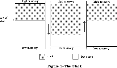 Figure 1–The Stack
By convention, the stack grows from high toward low memory addresses. The end of the stack that grows and shrinks is usually referred to as the “top” of the stack, even though it’s actually at the lower end of the stack in memory.
When programs in high-level languages declare static variables (such as with the Pascal VAR declaration), those variables are allocated on the stack.
The other method of dynamic memory allocation is from the heap. Heap space is allocated and released only at the program’s explicit request, through calls to the Memory Manager.
Space in the heap is allocated in blocks, which may be of any size needed for a particular object. The Memory Manager does all the necessary “housekeeping” to keep track of the blocks as they’re allocated and released. Because these operations can occur in any order, the heap doesn’t grow and shrink in an orderly way like the stack. After a program has been running for a while, the heap tends to become fragmented into a patchwork of allocated and free blocks, as shown in Figure 2.
Figure 1–The Stack
By convention, the stack grows from high toward low memory addresses. The end of the stack that grows and shrinks is usually referred to as the “top” of the stack, even though it’s actually at the lower end of the stack in memory.
When programs in high-level languages declare static variables (such as with the Pascal VAR declaration), those variables are allocated on the stack.
The other method of dynamic memory allocation is from the heap. Heap space is allocated and released only at the program’s explicit request, through calls to the Memory Manager.
Space in the heap is allocated in blocks, which may be of any size needed for a particular object. The Memory Manager does all the necessary “housekeeping” to keep track of the blocks as they’re allocated and released. Because these operations can occur in any order, the heap doesn’t grow and shrink in an orderly way like the stack. After a program has been running for a while, the heap tends to become fragmented into a patchwork of allocated and free blocks, as shown in Figure 2.
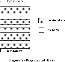 Figure 2–A Fragmented Heap
As a result of heap fragmentation, when the program asks to allocate a new block of a certain size, it may be impossible to satisfy the request even though there’s enough free space available, because the space is broken up into blocks smaller than the requested size. When this happens, the Memory Manager will try to create the needed space by compacting the heap: moving allocated blocks together in order to collect the free space into a single larger block
(see Figure 3).
Figure 2–A Fragmented Heap
As a result of heap fragmentation, when the program asks to allocate a new block of a certain size, it may be impossible to satisfy the request even though there’s enough free space available, because the space is broken up into blocks smaller than the requested size. When this happens, the Memory Manager will try to create the needed space by compacting the heap: moving allocated blocks together in order to collect the free space into a single larger block
(see Figure 3).
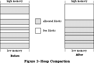 Figure 3–Heap Compaction
There’s a system heap that’s used by the Operating System and an application heap that’s used by the Toolbox and the application program.
_______________________________________________________________________________
»POINTERS AND HANDLES
_______________________________________________________________________________
The Memory Manager contains a few fundamental routines for allocating and releasing heap space. The NewPtr function allocates a block in the heap of a requested size and returns a pointer to the block. You can then make as many copies of the pointer as you need and use them in any way your program requires. When you’re finished with the block, you can release the memory it occupies
(returning it to available free space) with the DisposPtr procedure.
Once you’ve called DisposPtr, any pointers you may have to the block become invalid, since the block they’re supposed to point to no longer exists. You have to be careful not to use such “dangling” pointers. This type of bug can be very difficult to diagnose and correct, since its effects typically aren’t discovered until long after the pointer is left dangling.
Another way a pointer can be left dangling is for its underlying block to be moved to a different location within the heap. To avoid this problem, blocks that are referred to through simple pointers, as in Figure 4, are nonrelocatable. The Memory Manager will never move a nonrelocatable block, so you can rely on all pointers to it to remain correct for as long as the block remains allocated.
Figure 3–Heap Compaction
There’s a system heap that’s used by the Operating System and an application heap that’s used by the Toolbox and the application program.
_______________________________________________________________________________
»POINTERS AND HANDLES
_______________________________________________________________________________
The Memory Manager contains a few fundamental routines for allocating and releasing heap space. The NewPtr function allocates a block in the heap of a requested size and returns a pointer to the block. You can then make as many copies of the pointer as you need and use them in any way your program requires. When you’re finished with the block, you can release the memory it occupies
(returning it to available free space) with the DisposPtr procedure.
Once you’ve called DisposPtr, any pointers you may have to the block become invalid, since the block they’re supposed to point to no longer exists. You have to be careful not to use such “dangling” pointers. This type of bug can be very difficult to diagnose and correct, since its effects typically aren’t discovered until long after the pointer is left dangling.
Another way a pointer can be left dangling is for its underlying block to be moved to a different location within the heap. To avoid this problem, blocks that are referred to through simple pointers, as in Figure 4, are nonrelocatable. The Memory Manager will never move a nonrelocatable block, so you can rely on all pointers to it to remain correct for as long as the block remains allocated.
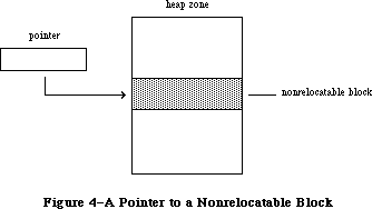 Figure 4–A Pointer to a Nonrelocatable Block
If all blocks in the heap were nonrelocatable, there would be no way to prevent the heap’s free space from becoming fragmented. Since the Memory Manager needs to be able to move blocks around in order to compact the heap, it also uses relocatable blocks. (All the allocated blocks shown above in Figure 3, the illustration of heap compaction, are relocatable.) To keep from creating dangling pointers, the Memory Manager maintains a single master pointer to each relocatable block. Whenever a relocatable block is created, a master pointer is allocated from the heap at the same time and set to point to the block. All references to the block are then made by double indirection, through a pointer to the master pointer, called a handle to the block (see Figure 5). If the Memory Manager needs to move the block during compaction, it has only to update the master pointer to point to the block’s new location; the master pointer itself is never moved. Since all copies of the handle point to this same master pointer, they can be relied on not to dangle, even after the block has been moved.
Figure 4–A Pointer to a Nonrelocatable Block
If all blocks in the heap were nonrelocatable, there would be no way to prevent the heap’s free space from becoming fragmented. Since the Memory Manager needs to be able to move blocks around in order to compact the heap, it also uses relocatable blocks. (All the allocated blocks shown above in Figure 3, the illustration of heap compaction, are relocatable.) To keep from creating dangling pointers, the Memory Manager maintains a single master pointer to each relocatable block. Whenever a relocatable block is created, a master pointer is allocated from the heap at the same time and set to point to the block. All references to the block are then made by double indirection, through a pointer to the master pointer, called a handle to the block (see Figure 5). If the Memory Manager needs to move the block during compaction, it has only to update the master pointer to point to the block’s new location; the master pointer itself is never moved. Since all copies of the handle point to this same master pointer, they can be relied on not to dangle, even after the block has been moved.
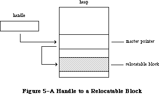 Figure 5–A Handle to a Relocatable Block
Relocatable blocks are moved only by the Memory Manager, and only at well-defined, predictable times. In particular, only the routines listed in Appendix B can cause blocks to move, and these routines can never be called from within an interrupt. If your program doesn’t call these routines, you can rely on blocks not being moved.
The NewHandle function allocates a block in the heap of a requested size and returns a handle to the block. You can then make as many copies of the handle as you need and use them in any way your program requires. When you’re finished with the block, you can free the space it occupies with the DisposHandle procedure.
Note: Toolbox routines that create new objects of various kinds, such as
NewWindow and NewControl, implicitly call the NewPtr and NewHandle
routines to allocate the space they need. There are also analogous
routines for releasing these objects, such as DisposeWindow and
DisposeControl.
If the Memory Manager can’t allocate a block of a requested size even after compacting the entire heap, it can try to free some space by purging blocks from the heap. Purging a block removes it from the heap and frees the space it occupies. The block’s master pointer is set to NIL, but the space occupied by the master pointer itself remains allocated. Any handles to the block now point to a NIL master pointer, and are said to be empty. If your program later needs to refer to the purged block, it can detect that the handle has become empty and ask the Memory Manager to reallocate the block. This operation updates the original master pointer, so that all handles to the block are left referring correctly to its new location (see Figure 6).
Warning: Reallocating a block recovers only the space it occupies, not its
contents. Any information the block contains is lost when the block
is purged. It’s up to your program to reconstitute the block’s
contents after reallocating it.
Relocatable and nonrelocatable are permanent properties of a block that can never be changed once the block is allocated. A relocatable block can also be locked or unlocked, purgeable or unpurgeable; your program can set and change these attributes as necessary. Locking a block temporarily prevents it from being moved, even if the heap is compacted. The block can later be unlocked, again allowing the Memory Manager to move it during compaction. A block can be purged only if it’s relocatable, unlocked, and purgeable. A newly allocated relocatable block is initially unlocked and unpurgeable.
Figure 5–A Handle to a Relocatable Block
Relocatable blocks are moved only by the Memory Manager, and only at well-defined, predictable times. In particular, only the routines listed in Appendix B can cause blocks to move, and these routines can never be called from within an interrupt. If your program doesn’t call these routines, you can rely on blocks not being moved.
The NewHandle function allocates a block in the heap of a requested size and returns a handle to the block. You can then make as many copies of the handle as you need and use them in any way your program requires. When you’re finished with the block, you can free the space it occupies with the DisposHandle procedure.
Note: Toolbox routines that create new objects of various kinds, such as
NewWindow and NewControl, implicitly call the NewPtr and NewHandle
routines to allocate the space they need. There are also analogous
routines for releasing these objects, such as DisposeWindow and
DisposeControl.
If the Memory Manager can’t allocate a block of a requested size even after compacting the entire heap, it can try to free some space by purging blocks from the heap. Purging a block removes it from the heap and frees the space it occupies. The block’s master pointer is set to NIL, but the space occupied by the master pointer itself remains allocated. Any handles to the block now point to a NIL master pointer, and are said to be empty. If your program later needs to refer to the purged block, it can detect that the handle has become empty and ask the Memory Manager to reallocate the block. This operation updates the original master pointer, so that all handles to the block are left referring correctly to its new location (see Figure 6).
Warning: Reallocating a block recovers only the space it occupies, not its
contents. Any information the block contains is lost when the block
is purged. It’s up to your program to reconstitute the block’s
contents after reallocating it.
Relocatable and nonrelocatable are permanent properties of a block that can never be changed once the block is allocated. A relocatable block can also be locked or unlocked, purgeable or unpurgeable; your program can set and change these attributes as necessary. Locking a block temporarily prevents it from being moved, even if the heap is compacted. The block can later be unlocked, again allowing the Memory Manager to move it during compaction. A block can be purged only if it’s relocatable, unlocked, and purgeable. A newly allocated relocatable block is initially unlocked and unpurgeable.
 Figure 6–Purging and Reallocating a Block
_______________________________________________________________________________
»General-Purpose Data Types
_______________________________________________________________________________
The Memory Manager includes a number of type definitions for general-purpose use. For working with pointers and handles, there are the following definitions:
TYPE SignedByte = -128..127;
Byte = 0..255;
Ptr = ^SignedByte;
Handle = ^Ptr;
SignedByte stands for an arbitrary byte in memory, just to give Ptr and Handle something to point to. You can define a buffer of, say, bufSize untyped memory bytes as a PACKED ARRAY[1..bufSize] OF SignedByte. Byte is an alternative definition that treats byte-length data as unsigned rather than signed quantities.
For working with strings, pointers to strings, and handles to strings, the Memory Manager includes the following definitions:
TYPE Str255 = STRING[255];
StringPtr = ^Str255;
StringHandle = ^StringPtr;
For treating procedures and functions as data objects, there’s the ProcPtr data type:
TYPE ProcPtr = Ptr;
For example, after the declarations
VAR aProcPtr: ProcPtr;
. . .
PROCEDURE MyProc;
BEGIN
. . .
END;
you can make aProcPtr point to MyProc by using Lisa Pascal’s @ operator, as follows:
aProcPtr := @MyProc
With the @ operator, you can assign procedures and functions to variables of type ProcPtr, embed them in data structures, and pass them as arguments to other routines. Notice, however, that the data type ProcPtr technically points to an arbitrary byte (SignedByte), not an actual routine. As a result, there’s no way in Pascal to access the underlying routine via this pointer in order to call it. Only routines written in assembly language (such as those in the Operating System and the Toolbox) can actually call the routine designated by a pointer of type ProcPtr.
Warning: You can’t use the @ operator with procedures or functions
whose declarations are nested within other routines.
Finally, for treating long integers as fixed-point numbers, there’s the following data type:
TYPE Fixed = LONGINT;
As illustrated in Figure 7, a fixed-point number is a 32-bit signed quantity containing an integer part in the high-order word and a fractional part in the low-order word. Negative numbers are the two’s complement; they’re formed by treating the fixed-point number as a long integer, inverting each bit, and adding 1 to the least significant bit.
Figure 6–Purging and Reallocating a Block
_______________________________________________________________________________
»General-Purpose Data Types
_______________________________________________________________________________
The Memory Manager includes a number of type definitions for general-purpose use. For working with pointers and handles, there are the following definitions:
TYPE SignedByte = -128..127;
Byte = 0..255;
Ptr = ^SignedByte;
Handle = ^Ptr;
SignedByte stands for an arbitrary byte in memory, just to give Ptr and Handle something to point to. You can define a buffer of, say, bufSize untyped memory bytes as a PACKED ARRAY[1..bufSize] OF SignedByte. Byte is an alternative definition that treats byte-length data as unsigned rather than signed quantities.
For working with strings, pointers to strings, and handles to strings, the Memory Manager includes the following definitions:
TYPE Str255 = STRING[255];
StringPtr = ^Str255;
StringHandle = ^StringPtr;
For treating procedures and functions as data objects, there’s the ProcPtr data type:
TYPE ProcPtr = Ptr;
For example, after the declarations
VAR aProcPtr: ProcPtr;
. . .
PROCEDURE MyProc;
BEGIN
. . .
END;
you can make aProcPtr point to MyProc by using Lisa Pascal’s @ operator, as follows:
aProcPtr := @MyProc
With the @ operator, you can assign procedures and functions to variables of type ProcPtr, embed them in data structures, and pass them as arguments to other routines. Notice, however, that the data type ProcPtr technically points to an arbitrary byte (SignedByte), not an actual routine. As a result, there’s no way in Pascal to access the underlying routine via this pointer in order to call it. Only routines written in assembly language (such as those in the Operating System and the Toolbox) can actually call the routine designated by a pointer of type ProcPtr.
Warning: You can’t use the @ operator with procedures or functions
whose declarations are nested within other routines.
Finally, for treating long integers as fixed-point numbers, there’s the following data type:
TYPE Fixed = LONGINT;
As illustrated in Figure 7, a fixed-point number is a 32-bit signed quantity containing an integer part in the high-order word and a fractional part in the low-order word. Negative numbers are the two’s complement; they’re formed by treating the fixed-point number as a long integer, inverting each bit, and adding 1 to the least significant bit.
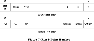 Figure 7–Fixed-Point Number
_______________________________________________________________________________
»Type Coercion
Because of Pascal’s strong typing rules, you can’t directly assign a value of type Ptr to a variable of some other pointer type, or pass it as a parameter of some other pointer type. Instead, you have to coerce the pointer from one type to another. For example, assume the following declarations have been made:
TYPE Thing = RECORD
. . .
END;
ThingPtr = ^Thing;
ThingHandle = ^ThingPtr;
VAR aPtr: Ptr;
aThingPtr: ThingPtr;
aThingHandle: ThingHandle;
In the Lisa Pascal statement
aThingPtr := ThingPtr(NewPtr(SIZEOF(Thing)))
NewPtr allocates heap space for a new record of type Thing and returns a pointer of type Ptr, which is then coerced to type ThingPtr so it can be assigned to aThingPtr. The statement
DisposPtr(Ptr(aThingPtr))
disposes of the record pointed to by aThingPtr, first coercing the pointer to type Ptr (as required by the DisposPtr procedure). Similar calls to NewHandle and DisposHandle would require coercion between the data types Handle and ThingHandle. Given a pointer aPtr of type Ptr, you can make aThingPtr point to the same object as aPtr with the assignment
aThingPtr := ThingPtr(aPtr)
or you can refer to a field of a record of type Thing with the expression
ThingPtr(aPtr)^.field
In fact, you can use this same syntax to equate any two variables of the same length. For example:
VAR aChar: CHAR;
aByte: Byte;
. . .
aByte := Byte(aChar)
You can also use the Lisa Pascal functions ORD, ORD4, and POINTER, to coerce variables of different length from one type to another. For example:
VAR anInteger: INTEGER;
aLongInt: LONGINT;
aPointer: Ptr;
. . .
anInteger := ORD(aLongInt); {two low-order bytes only}
anInteger := ORD(aPointer); {two low-order bytes only}
aLongInt := ORD(anInteger); {packed into high-order bytes}
aLongInt := ORD4(anInteger); {packed into low-order bytes}
aLongInt := ORD(aPointer);
aPointer := POINTER(anInteger);
aPointer := POINTER(aLongInt)
Assembly-language note: Of course, assembly-language programmers needn’t
bother with type coercion.
_______________________________________________________________________________
»SUMMARY
_______________________________________________________________________________
TYPE SignedByte = -128..127;
Byte = 0..255;
Ptr = ^SignedByte;
Handle = ^Ptr;
Str255 = STRING[255];
StringPtr = ^Str255;
StringHandle = ^StringPtr;
ProcPtr = Ptr;
Fixed = LONGINT
Further Reference:
_______________________________________________________________________________
Memory Manager
Technical Note #18, TextEdit Conversion Utility
Technical Note #42, Pascal Routines Passed by Pointer
Figure 7–Fixed-Point Number
_______________________________________________________________________________
»Type Coercion
Because of Pascal’s strong typing rules, you can’t directly assign a value of type Ptr to a variable of some other pointer type, or pass it as a parameter of some other pointer type. Instead, you have to coerce the pointer from one type to another. For example, assume the following declarations have been made:
TYPE Thing = RECORD
. . .
END;
ThingPtr = ^Thing;
ThingHandle = ^ThingPtr;
VAR aPtr: Ptr;
aThingPtr: ThingPtr;
aThingHandle: ThingHandle;
In the Lisa Pascal statement
aThingPtr := ThingPtr(NewPtr(SIZEOF(Thing)))
NewPtr allocates heap space for a new record of type Thing and returns a pointer of type Ptr, which is then coerced to type ThingPtr so it can be assigned to aThingPtr. The statement
DisposPtr(Ptr(aThingPtr))
disposes of the record pointed to by aThingPtr, first coercing the pointer to type Ptr (as required by the DisposPtr procedure). Similar calls to NewHandle and DisposHandle would require coercion between the data types Handle and ThingHandle. Given a pointer aPtr of type Ptr, you can make aThingPtr point to the same object as aPtr with the assignment
aThingPtr := ThingPtr(aPtr)
or you can refer to a field of a record of type Thing with the expression
ThingPtr(aPtr)^.field
In fact, you can use this same syntax to equate any two variables of the same length. For example:
VAR aChar: CHAR;
aByte: Byte;
. . .
aByte := Byte(aChar)
You can also use the Lisa Pascal functions ORD, ORD4, and POINTER, to coerce variables of different length from one type to another. For example:
VAR anInteger: INTEGER;
aLongInt: LONGINT;
aPointer: Ptr;
. . .
anInteger := ORD(aLongInt); {two low-order bytes only}
anInteger := ORD(aPointer); {two low-order bytes only}
aLongInt := ORD(anInteger); {packed into high-order bytes}
aLongInt := ORD4(anInteger); {packed into low-order bytes}
aLongInt := ORD(aPointer);
aPointer := POINTER(anInteger);
aPointer := POINTER(aLongInt)
Assembly-language note: Of course, assembly-language programmers needn’t
bother with type coercion.
_______________________________________________________________________________
»SUMMARY
_______________________________________________________________________________
TYPE SignedByte = -128..127;
Byte = 0..255;
Ptr = ^SignedByte;
Handle = ^Ptr;
Str255 = STRING[255];
StringPtr = ^Str255;
StringHandle = ^StringPtr;
ProcPtr = Ptr;
Fixed = LONGINT
Further Reference:
_______________________________________________________________________________
Memory Manager
Technical Note #18, TextEdit Conversion Utility
Technical Note #42, Pascal Routines Passed by Pointer
Using Assembly Language
_______________________________________________________________________________
USING ASSEMBLY LANGUAGE
_______________________________________________________________________________
About This Chapter
Definition Files
Pascal Data Types
The Trap Dispatch Table
The Trap Mechanism
Format of Trap Words
Trap Macros
Calling Conventions
Stack-Based Routines
Register-Based Routines
Macro Arguments
Result Codes
Register-Saving Conventions
Pascal Interface to the Toolbox and Operating System
Mixing Pascal and Assembly Language
Summary
_______________________________________________________________________________
»ABOUT THIS CHAPTER
_______________________________________________________________________________
This chapter gives you general information that you’ll need to write all or part of your Macintosh application program in assembly language. It assumes you already know how to write assembly-language programs for the Motorola MC68000, the microprocessor in the Macintosh.
_______________________________________________________________________________
»DEFINITION FILES
_______________________________________________________________________________
The primary aids to assembly-language programmers are a set of definition files for symbolic names used in assembly-language programs. The definition files include equate files, which equate symbolic names with values, and macro files, which define the macros used to call Toolbox and Operating System routines from assembly language. The equate files define a variety of symbolic names for various purposes, such as:
• useful numeric quantities
• masks and bit numbers
• offsets into data structures
• addresses of global variables (which in turn often contain addresses)
It’s a good idea to always use the symbolic names defined in an equate file in place of the corresponding numeric values (even if you know them), since some of these values may change. Note that the names of the offsets for a data structure don’t always match the field names in the corresponding Pascal definition. In the documentation, the definitions are normally shown in their Pascal form; the corresponding offset constants for assembly language use are listed in the summary at the end of each chapter.
Some generally useful global variables defined in the equate files are as follows:
Name Contents
OneOne $00010001
MinusOne $FFFFFFFF
Lo3Bytes $00FFFFFF
Scratch20 20-byte scratch area
Scratch8 8-byte scratch area
ToolScratch 8-byte scratch area
ApplScratch 12-byte scratch area reserved for use by applications
Scratch20, Scratch8, and ToolScratch will not be preserved across calls to the routines in the Macintosh ROM. ApplScratch will be preserved; it should be used only by application programs and not by desk accessories or other drivers.
Other global variables are described where relevant in Inside Macintosh. A list of all the variables described is given in Appendix D.
_______________________________________________________________________________
»PASCAL DATA TYPES
_______________________________________________________________________________
Pascal’s strong typing ability lets Pascal programmers write programs without really considering the size of variables. But assembly language programmers must keep track of the size of every variable. The sizes of the standard Pascal data types, and some of the basic types defined in the Memory Manager, are listed below. (See the Apple Numerics Manual for more information about SINGLE, DOUBLE, EXTENDED, and COMP.)
Type Size Contents
INTEGER 2 bytes Two’s complement integer
LONGINT 4 bytes Two’s complement integer
BOOLEAN 1 byte Boolean value in bit 0
CHAR 2 bytes Extended ASCII code in low-order byte
SINGLE (or REAL)
4 bytes IEEE standard single format
DOUBLE 8 bytes IEEE standard double format
EXTENDED 10 bytes IEEE standard extended format
COMP (or COMPUTATIONAL)
8 bytes Two’s complement integer with reserved value
STRING[n] n+1 bytes Byte containing string length (not counting
length byte) followed by bytes containing
ASCII codes of characters in string
SignedByte 1 byte Two’s complement integer
Byte 2 bytes Value in low-order byte
Ptr 4 bytes Address of data
Handle 4 bytes Address of master pointer
Other data types are constructed from these. For some commonly used data types, the size in bytes is available as a predefined constant.
Before allocating space for any variable whose size is greater than one byte, Pascal adds “padding” to the next word boundary, if it isn’t already at a word boundary. It does this not only when allocating variables declared successively in VAR statements, but also within arrays and records. As you would expect, the size of a Pascal array or record is the sum of the sizes of all its elements or fields (which are stored with the first one at the lowest address). For example, the size of the data type
TYPE TestRecord = RECORD
testHandle: Handle;
testBoolA: BOOLEAN;
testBoolB: BOOLEAN;
testChar: CHAR
END;
is eight bytes: four for the handle, one each for the Booleans, and two for the character. If the testBoolB field weren’t there, the size would be the same, because of the byte of padding Pascal would add to make the character begin on a word boundary.
In a packed record or array, type BOOLEAN is stored as a bit, and types CHAR and Byte are stored as bytes. The padding rule described above still applies. For example, if the TestRecord data type shown above were declared as PACKED RECORD, it would occupy only six bytes: four for the handle, one for the Booleans (each stored in a bit), and one for the character. If the last field were INTEGER rather than CHAR, padding before the two byte integer field would cause the size to be eight bytes.
Note: The packing algorithm may not be what you expect. If you need to know
exactly how data is packed, or if you have questions about the size of
a particular data type, the best thing to do is write a test program
in Pascal and look at the results. (You can use the SIZEOF function to
get the size.)
_______________________________________________________________________________
»THE TRAP DISPATCH TABLE
_______________________________________________________________________________
The Toolbox and Operating System reside in ROM. However, to allow flexibility for future development, application code must be kept free of any specific ROM addresses. So all references to Toolbox and Operating System routines are made indirectly through the trap dispatch table in RAM, which contains the addresses of the routines. As long as the location of the trap dispatch table is known, the routines themselves can be moved to different locations in ROM without disturbing the operation of programs that depend on them.
Information about the locations of the various Toolbox and Operating System routines is encoded in compressed form in the ROM itself. When the system starts up, this encoded information is expanded to form the trap dispatch table. Because the trap dispatch table resides in RAM, individual entries can be
“patched” to point to addresses other than the original ROM address. This allows changes to be made in the ROM code by loading corrected versions of individual routines into RAM at system startup and patching the trap dispatch table to point to them. It also allows an application program to replace specific Toolbox and Operating System routines with its own “custom” versions. A pair of utility routines for manipulating the trap dispatch table, GetTrapAddress and SetTrapAddress, are described in the Operating System Utilities chapter.
In the 64K ROM, references to both Toolbox and Operating System routines are made through a single trap dispatch table. For compactness, entries in that table are encoded into one word each. The high-order bit of each entry tells whether the routine resides in ROM (0) or RAM (1). The remaining 15 bits give the offset of the routine relative to a base address. For routines in ROM, this base address is the beginning of the ROM; for routines in RAM, it’s the beginning of the system heap. The two base addresses are kept in a pair of global variables named ROMBase and RAMBase. Using 15-bit unsigned word offsets, the range of locations that the trap dispatch table can address is limited to 64K bytes. Also, the interleaving of Operating System and Toolbox trap numbers limits the total number of traps to 512 and means that no two traps can be represented by the same number.
In the 128K ROM, the Toolbox and Operating System traps have separate dispatch tables. Instead of a packed format, entries in these dispatch tables are stored as full long-word addresses so the dispatcher makes no distinction between ROM and RAM addresses. The Operating System dispatch table consists of 256 long words, from address $400 through $7FF; this replaces the old dispatch table of 512 words. The Toolbox table consists of 512 long words, from address $C00 through $13FF.
Warning: The format of the trap dispatch tables may be different in future
versions of Macintosh system software. If it’s absolutely necessary
that you manipulate the trap dispatch tables, use the Operating
System Utility routines NGetTrapAddress and NSetTrapAddress (or with
the 64K ROM, GetTrapAddress and SetTrapAddress); they’re described
in the Operating System Utilities chapter.
The offset in a trap dispatch table entry is expressed in words instead of bytes, taking advantage of the fact that instructions must always fall on word boundaries (even byte addresses). As illustrated in Figure 1, the system does the following to find the absolute address of the routine:
1. checks the high-order bit of the trap dispatch table entry to find
out which base address to use
2. doubles the offset to convert it from words to bytes (by left shifting
one bit)
3. adds the result to the designated base address
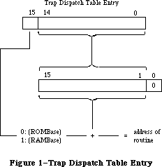 Figure 1–Trap Dispatch Table Entry
Using 15-bit word offsets, the trap dispatch table can address locations within a range of 32K words, or 64K bytes, from the base address. Starting from ROMBase, this range is big enough to cover the entire ROM; but only slightly more than half of the 128K RAM lies within range of RAMBase. RAMBase is set to the beginning of the system heap to maximize the amount of useful space within range; locations below the start of the heap are used to hold global system data and can never contain executable code. If the heap is big enough, however, it’s possible for some of the application’s code to lie beyond the upper end of the trap dispatch table’s range. Any such code is inaccessible through the trap dispatch table.
Note: This problem is particularly acute on the Macintosh 512K and
Macintosh XL. To make sure they lie within range of RAMBase,
patches to Toolbox and Operating System routines are typically
placed in the system heap rather than the application heap.
_______________________________________________________________________________
»THE TRAP MECHANISM
_______________________________________________________________________________
Calls to the Toolbox and Operating System via the trap dispatch table are implemented by means of the MC68000’s “1010 emulator” trap. To issue such a call in assembly language, you use one of the trap macros defined in the macro files. When you assemble your program, the macro generates a trap word in the machine language code. A trap word always begins with the hexadecimal digit $A
(binary 1010); the rest of the word identifies the routine you’re calling, along with some additional information pertaining to the call.
Note: A list of all Macintosh trap words is given in Appendix C.
Instruction words beginning with $A or $F (“A-line” or “F-line” instructions) don’t correspond to any valid machine language instruction, and are known as unimplemented instructions. They’re used to augment the processor’s native instruction set with additional operations that are “emulated” in software instead of being executed directly by the hardware. A-line instructions are reserved for use by Apple; on a Macintosh, they provide access to the Toolbox and Operating System routines. Attempting to execute such an instruction causes a trap to the trap dispatcher, which examines the bit pattern of the trap word to determine what operation it stands for, looks up the address of the corresponding routine in the trap dispatch table, and jumps to the routine.
Note: F-line instructions are reserved by Motorola for use in future
processors.
_______________________________________________________________________________
»Format of Trap Words
As noted above, a trap word always contains $A in bits 12-15. Bit 11 determines how the remainder of the word will be interpreted; usually it’s 0 for Operating System calls and 1 for Toolbox calls, though there are some exceptions.
Figure 2 shows the Toolbox trap word format. Bits 0-8 form the trap number (an index into the trap dispatch table), identifying the particular routine being called. Bit 9 is reserved for future use. Bit 10 is the “auto-pop” bit; this bit is used by language systems that, rather than directly invoking the trap like Lisa Pascal, do a JSR to the trap word followed immediately by a return to the calling routine. In this case, the return addresses for the both the JSR and the trap get pushed onto the stack, in that order. The auto-pop bit causes the trap dispatcher to pop the trap’s return address from the stack and return directly to the calling program.
Figure 1–Trap Dispatch Table Entry
Using 15-bit word offsets, the trap dispatch table can address locations within a range of 32K words, or 64K bytes, from the base address. Starting from ROMBase, this range is big enough to cover the entire ROM; but only slightly more than half of the 128K RAM lies within range of RAMBase. RAMBase is set to the beginning of the system heap to maximize the amount of useful space within range; locations below the start of the heap are used to hold global system data and can never contain executable code. If the heap is big enough, however, it’s possible for some of the application’s code to lie beyond the upper end of the trap dispatch table’s range. Any such code is inaccessible through the trap dispatch table.
Note: This problem is particularly acute on the Macintosh 512K and
Macintosh XL. To make sure they lie within range of RAMBase,
patches to Toolbox and Operating System routines are typically
placed in the system heap rather than the application heap.
_______________________________________________________________________________
»THE TRAP MECHANISM
_______________________________________________________________________________
Calls to the Toolbox and Operating System via the trap dispatch table are implemented by means of the MC68000’s “1010 emulator” trap. To issue such a call in assembly language, you use one of the trap macros defined in the macro files. When you assemble your program, the macro generates a trap word in the machine language code. A trap word always begins with the hexadecimal digit $A
(binary 1010); the rest of the word identifies the routine you’re calling, along with some additional information pertaining to the call.
Note: A list of all Macintosh trap words is given in Appendix C.
Instruction words beginning with $A or $F (“A-line” or “F-line” instructions) don’t correspond to any valid machine language instruction, and are known as unimplemented instructions. They’re used to augment the processor’s native instruction set with additional operations that are “emulated” in software instead of being executed directly by the hardware. A-line instructions are reserved for use by Apple; on a Macintosh, they provide access to the Toolbox and Operating System routines. Attempting to execute such an instruction causes a trap to the trap dispatcher, which examines the bit pattern of the trap word to determine what operation it stands for, looks up the address of the corresponding routine in the trap dispatch table, and jumps to the routine.
Note: F-line instructions are reserved by Motorola for use in future
processors.
_______________________________________________________________________________
»Format of Trap Words
As noted above, a trap word always contains $A in bits 12-15. Bit 11 determines how the remainder of the word will be interpreted; usually it’s 0 for Operating System calls and 1 for Toolbox calls, though there are some exceptions.
Figure 2 shows the Toolbox trap word format. Bits 0-8 form the trap number (an index into the trap dispatch table), identifying the particular routine being called. Bit 9 is reserved for future use. Bit 10 is the “auto-pop” bit; this bit is used by language systems that, rather than directly invoking the trap like Lisa Pascal, do a JSR to the trap word followed immediately by a return to the calling routine. In this case, the return addresses for the both the JSR and the trap get pushed onto the stack, in that order. The auto-pop bit causes the trap dispatcher to pop the trap’s return address from the stack and return directly to the calling program.
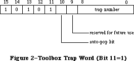 Figure 2–Toolbox Trap Word (Bit 11=1)
For Operating System calls, only the low order eight bits (bits 0-7) are used for the trap number (see Figure 3). Thus of the 512 entries in the trap dispatch table, only the first 256 can be used for Operating System traps. Bit 8 of an Operating System trap has to do with register usage and is discussed below under “Register Saving Conventions”. Bits 9 and 10 have specialized meanings depending on which routine you’re calling, and are covered where relevant in other chapters.
Figure 2–Toolbox Trap Word (Bit 11=1)
For Operating System calls, only the low order eight bits (bits 0-7) are used for the trap number (see Figure 3). Thus of the 512 entries in the trap dispatch table, only the first 256 can be used for Operating System traps. Bit 8 of an Operating System trap has to do with register usage and is discussed below under “Register Saving Conventions”. Bits 9 and 10 have specialized meanings depending on which routine you’re calling, and are covered where relevant in other chapters.
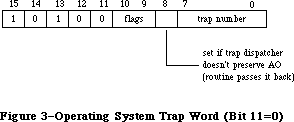 Figure 3–Operating System Trap Word (Bit 11=0)
As described above, a trap word begins with the hexadecimal digit $A (binary 1010); the rest of the word identifies the routine you’re calling, along with additional information pertaining to the call.
In the 64K ROM, an Operating System trap and a Toolbox trap cannot have the same trap number; the GetTrapAddress and SetTrapAddress routines do not distinguish between Toolbox and Operating System traps.
Since each group has its own dispatch table in the 128K ROM, there can be a Toolbox trap and an Operating System trap with the same trap number. Two new routines—NGetTrapAddress and NSetTrapAddress—have been added; they use bits 9 and 10 of their trap word for specifying the group to which a routine belongs.
_______________________________________________________________________________
»Trap Macros
The names of all trap macros begin with the underscore character (_), followed by the name of the corresponding routine. As a rule, the macro name is the same as the name used to call the routine from Pascal, as given in the Toolbox and Operating System documentation. For example, to call the Window Manager routine NewWindow, you would use an instruction with the macro name _NewWindow in the opcode field. There are some exceptions, however, in which the spelling of the macro name differs from the name of the Pascal routine itself; these are noted in the documentation for the individual routines.
Note: The reason for the exceptions is that assembler names must be unique
to eight characters. Since one character is taken up by the underscore,
special macro names must be used for Pascal routines whose names aren’t
unique to seven characters.
Trap macros for Toolbox calls take no arguments; those for Operating System calls may have as many as three optional arguments. The first argument, if present, is used to load a register with a parameter value for the routine
you’re calling, and is discussed below under “Register Based Routines”. The remaining arguments control the settings of the various flag bits in the trap word. The form of these arguments varies with the meanings of the flag bits, and is described in the chapters on the relevant parts of the Operating System.
_______________________________________________________________________________
»CALLING CONVENTIONS
_______________________________________________________________________________
The calling conventions for Toolbox and Operating System routines fall into two categories: stack based and register based. As the terms imply, stack based routines communicate via the stack, following the same conventions used by the Pascal Compiler for routines written in Lisa Pascal, while register based routines receive their parameters and return their results in registers. Before calling any Toolbox or Operating System routine, you have to set up the parameters in the way the routine expects.
Note: As a general rule, Toolbox routines are stack based and Operating
System routines register based, but there are exceptions on both sides.
Throughout Inside Macintosh, register based calling conventions are
given for all routines that have them; if none is shown, then the
routine is stack based.
_______________________________________________________________________________
»Stack-Based Routines
To call a stack based routine from assembly language, you have to set up the parameters on the stack in the same way the compiled object code would if your program were written in Pascal. If the routine you’re calling is a function, its result is returned on the stack. The number and types of parameters, and the type of result returned by a function, depend on the routine being called. The number of bytes each parameter or result occupies on the stack depends on its type:
Type of parameter
or function
result Size Contents
INTEGER 2 bytes Two’s complement integer
LONGINT 4 bytes Two’s complement integer
BOOLEAN 2 bytes Boolean value in bit 0 of high-order byte
CHAR 2 bytes Extended ASCII code in low-order byte
SINGLE (or REAL), DOUBLE, COMP (or COMPUTATIONAL)
4 bytes Pointer to value converted to EXTENDED
EXTENDED 4 bytes Pointer to value
STRING[n] 4 bytes Pointer to string (first byte
pointed to is length byte)
SignedByte 2 bytes Value in low-order byte
Byte 2 bytes Value in low-order byte
Ptr 4 bytes Address of data
Handle 4 bytes Address of master pointer
Record or array 2 or 4 Contents of structure (padded to
bytes word boundary) if <= 4 bytes,
otherwise pointer to structure
VAR parameter 4 bytes Address of variable, regardless of type
The steps to take to call the routine are as follows:
1. If it’s a function, reserve space on the stack for the result.
2. Push the parameters onto the stack in the order they occur in
the routine’s Pascal definition.
3. Call the routine by executing the corresponding trap macro.
The trap pushes the return address onto the stack, along with an extra word of processor status information. The trap dispatcher removes this extra status word, leaving the stack in the state shown in Figure 4 on entry to the routine. The routine itself is responsible for removing its own parameters from the stack before returning. If it’s a function, it leaves its result on top of the stack in the space reserved for it; if it’s a procedure, it restores the stack to the same state it was in before the call.
Figure 3–Operating System Trap Word (Bit 11=0)
As described above, a trap word begins with the hexadecimal digit $A (binary 1010); the rest of the word identifies the routine you’re calling, along with additional information pertaining to the call.
In the 64K ROM, an Operating System trap and a Toolbox trap cannot have the same trap number; the GetTrapAddress and SetTrapAddress routines do not distinguish between Toolbox and Operating System traps.
Since each group has its own dispatch table in the 128K ROM, there can be a Toolbox trap and an Operating System trap with the same trap number. Two new routines—NGetTrapAddress and NSetTrapAddress—have been added; they use bits 9 and 10 of their trap word for specifying the group to which a routine belongs.
_______________________________________________________________________________
»Trap Macros
The names of all trap macros begin with the underscore character (_), followed by the name of the corresponding routine. As a rule, the macro name is the same as the name used to call the routine from Pascal, as given in the Toolbox and Operating System documentation. For example, to call the Window Manager routine NewWindow, you would use an instruction with the macro name _NewWindow in the opcode field. There are some exceptions, however, in which the spelling of the macro name differs from the name of the Pascal routine itself; these are noted in the documentation for the individual routines.
Note: The reason for the exceptions is that assembler names must be unique
to eight characters. Since one character is taken up by the underscore,
special macro names must be used for Pascal routines whose names aren’t
unique to seven characters.
Trap macros for Toolbox calls take no arguments; those for Operating System calls may have as many as three optional arguments. The first argument, if present, is used to load a register with a parameter value for the routine
you’re calling, and is discussed below under “Register Based Routines”. The remaining arguments control the settings of the various flag bits in the trap word. The form of these arguments varies with the meanings of the flag bits, and is described in the chapters on the relevant parts of the Operating System.
_______________________________________________________________________________
»CALLING CONVENTIONS
_______________________________________________________________________________
The calling conventions for Toolbox and Operating System routines fall into two categories: stack based and register based. As the terms imply, stack based routines communicate via the stack, following the same conventions used by the Pascal Compiler for routines written in Lisa Pascal, while register based routines receive their parameters and return their results in registers. Before calling any Toolbox or Operating System routine, you have to set up the parameters in the way the routine expects.
Note: As a general rule, Toolbox routines are stack based and Operating
System routines register based, but there are exceptions on both sides.
Throughout Inside Macintosh, register based calling conventions are
given for all routines that have them; if none is shown, then the
routine is stack based.
_______________________________________________________________________________
»Stack-Based Routines
To call a stack based routine from assembly language, you have to set up the parameters on the stack in the same way the compiled object code would if your program were written in Pascal. If the routine you’re calling is a function, its result is returned on the stack. The number and types of parameters, and the type of result returned by a function, depend on the routine being called. The number of bytes each parameter or result occupies on the stack depends on its type:
Type of parameter
or function
result Size Contents
INTEGER 2 bytes Two’s complement integer
LONGINT 4 bytes Two’s complement integer
BOOLEAN 2 bytes Boolean value in bit 0 of high-order byte
CHAR 2 bytes Extended ASCII code in low-order byte
SINGLE (or REAL), DOUBLE, COMP (or COMPUTATIONAL)
4 bytes Pointer to value converted to EXTENDED
EXTENDED 4 bytes Pointer to value
STRING[n] 4 bytes Pointer to string (first byte
pointed to is length byte)
SignedByte 2 bytes Value in low-order byte
Byte 2 bytes Value in low-order byte
Ptr 4 bytes Address of data
Handle 4 bytes Address of master pointer
Record or array 2 or 4 Contents of structure (padded to
bytes word boundary) if <= 4 bytes,
otherwise pointer to structure
VAR parameter 4 bytes Address of variable, regardless of type
The steps to take to call the routine are as follows:
1. If it’s a function, reserve space on the stack for the result.
2. Push the parameters onto the stack in the order they occur in
the routine’s Pascal definition.
3. Call the routine by executing the corresponding trap macro.
The trap pushes the return address onto the stack, along with an extra word of processor status information. The trap dispatcher removes this extra status word, leaving the stack in the state shown in Figure 4 on entry to the routine. The routine itself is responsible for removing its own parameters from the stack before returning. If it’s a function, it leaves its result on top of the stack in the space reserved for it; if it’s a procedure, it restores the stack to the same state it was in before the call.
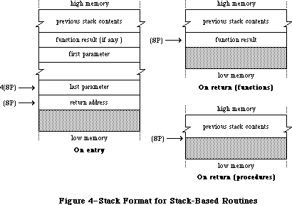 Figure 4–Stack Format for Stack Based Routines
For example, the Window Manager function GrowWindow is defined in Pascal as follows:
FUNCTION GrowWindow (theWindow: WindowPtr; startPt: Point;
sizeRect: Rect) : LONGINT;
To call this function from assembly language, you’d write something like the following:
SUBQ.L #4,SP ;make room for LONGINT result
MOVE.L theWindow,-(SP) ;push window pointer
MOVE.L startPt,-(SP) ;a Point is a 4-byte record,
;so push actual contents
PEA sizeRect ;a Rect is an 8-byte record,
;so push a pointer to it
_GrowWindow ;trap to routine
MOVE.L (SP)+,D3 ;pop result from stack
Although the MC68000 hardware provides for separate user and supervisor stacks, each with its own stack pointer, the Macintosh maintains only one stack. All application programs run in supervisor mode and share the same stack with the system; the user stack pointer isn’t used.
Warning: For compatibility with future versions of the Macintosh, your
program should not rely on capabilities available only in
supervisor mode (such as the instruction RTE).
Remember that the stack pointer must always be aligned on a word boundary. This is why, for example, a Boolean parameter occupies two bytes; it’s actually the Boolean value followed by a byte of padding. Because all Macintosh application code runs in the MC68000’s supervisor mode, an odd stack pointer will cause a
“double bus fault”: an unrecoverable system failure that causes the system to restart.
To keep the stack pointer properly aligned, the MC68000 automatically adjusts the pointer by 2 instead of 1 when you move a byte length value to or from the stack. This happens only when all of the following three conditions are met:
• A one byte value is being transferred.
• Either the source or the destination is specified by
predecrement or postincrement addressing.
• The register being decremented or incremented is the stack pointer (A7).
An extra, unused byte will automatically be added in the low order byte to keep the stack pointer even. (Note that if you need to move a character to or from the stack, you must explicitly use a full word of data, with the character in the low order byte.)
Warning: If you use any other method to manipulate the stack pointer, it’s
your responsibility to make sure the pointer stays properly aligned.
Note: Some Toolbox and Operating System routines accept the address of
one of your own routines as a parameter, and call that routine under
certain circumstances. In these cases, you must set up your routine
to be stack based.
_______________________________________________________________________________
»Register-Based Routines
By convention, register based routines normally use register A0 for passing addresses (such as pointers to data objects) and D0 for other data values (such as integers). Depending on the routine, these registers may be used to pass parameters to the routine, result values back to the calling program, or both. For routines that take more than two parameters (one address and one data
value), the parameters are normally collected in a parameter block in memory and a pointer to the parameter block is passed in A0. However, not all routines obey these conventions; for example, some expect parameters in other registers, such as A1. See the description of each individual routine for details.
Whatever the conventions may be for a particular routine, it’s up to you to set up the parameters in the appropriate registers before calling the routine. For instance, the Memory Manager procedure BlockMove, which copies a block of consecutive bytes from one place to another in memory, expects to find the address of the first source byte in register A0, the address of the first destination location in A1, and the number of bytes to be copied in D0. So you might write something like
LEA src(A5),A0 ;source address in A0
LEA dest(A5),A1 ;destination address in A1
MOVEQ #20,D0 ;byte count in D0
_BlockMove ; trap to routine
»Macro Arguments
The following information applies to the Lisa Workshop Assembler. If you’re using some other assembler, you should check its documentation to find out whether this information applies.
Many register based routines expect to find an address of some sort in register A0. You can specify the contents of that register as an argument to the macro instead of explicitly setting up the register yourself. The first argument you supply to the macro, if any, represents an address to be passed in A0. The macro will load the register with an LEA (Load Effective Address) instruction before trapping to the routine. So, for instance, to perform a Read operation on a file, you could set up the parameter block for the operation and then use the instruction
_Read paramBlock ;trap to routine with pointer to
; parameter block in A0
This feature is purely a convenience, and is optional: If you don’t supply any arguments to a trap macro, or if the first argument is null, the LEA to A0 will be omitted from the macro expansion. Notice that A0 is loaded with the address denoted by the argument, not the contents of that address.
Note: You can use any of the MC68000’s addressing modes to specify this
address, with one exception: You can’t use the two register indexing
mode (“address register indirect with index and displacement”). An
instruction such as
_Read offset(A3,D5)
won’t work properly, because the comma separating the two registers
will be taken as a delimiter marking the end of the macro argument.
»Result Codes
Many register-based routines return a result code in the low order word of register D0 to report successful completion or failure due to some error condition. A result code of 0 indicates that the routine was completed successfully. Just before returning from a register based call, the trap dispatcher tests the low order word of D0 with a TST.W instruction to set the processor’s condition codes. You can then check for an error by branching directly on the condition codes, without any explicit test of your own. For example:
_PurgeMem ;trap to routine
BEQ NoError ;branch if no error
. . . ;handle error
Warning: Not all register based routines return a result code. Some leave
the contents of D0 unchanged; others use the full 32 bits of the
register to return a long word result. See the descriptions of
individual routines for details.
_______________________________________________________________________________
»Register-Saving Conventions
All Toolbox and Operating System routines preserve the contents of all registers except A0, A1, and D0-D2 (and of course A7, which is the stack pointer). In addition, for register based routines, the trap dispatcher saves registers A1, D1, and D2 before dispatching to the routine and restores them before returning to the calling program. A7 and D0 are never restored; whatever the routine leaves in these registers is passed back unchanged to the calling program, allowing the routine to manipulate the stack pointer as appropriate and to return a result code.
Whether the trap dispatcher preserves register A0 for a register based trap depends on the setting of bit 8 of the trap word: If this bit is 0, the trap dispatcher saves and restores A0; if it’s 1, the routine passes back A0 unchanged. Thus bit 8 of the trap word should be set to 1 only for those routines that return a result in A0, and to 0 for all other routines. The trap macros automatically set this bit correctly for each routine, so you never have to worry about it yourself.
Stack based traps preserve only registers A2-A6 and D3-D7. If you want to preserve any of the other registers, you have to save them yourself before trapping to the routine - typically on the stack with a MOVEM (Move Multiple) instruction - and restore them afterward.
Warning: When an application starts up, register A5 is set to point to the
boundary between the application globals and the application
parameters (see the memory map in the Memory Manager chapter for
details). Certain parts of the system rely on finding A5 set up
properly (for instance, the first application parameter is a
pointer to the first QuickDraw global variable), so you have to
be a bit more careful about preserving this register. The safest
policy is never to touch A5 at all. If you must use it for your
own purposes, just saving its contents at the beginning of a
routine and restoring them before returning isn’t enough: You
have to be sure to restore it before any call that might depend
on it. The correct setting of A5 is always available in the global
variable CurrentA5.
Note: Any routine in your application that may be called as the result
of a Toolbox or Operating System call shouldn’t rely on the value
of any register except A5, which shouldn’t change.
_______________________________________________________________________________
»Pascal Interface to the Toolbox and Operating System
When you call a register based Toolbox or Operating System routine from Pascal, you’re actually calling an interface routine that fetches the parameters from the stack where the Pascal calling program left them, puts them in the registers where the routine expects them, and then traps to the routine. On return, it moves the routine’s result, if any, from a register to the stack and then returns to the calling program. (For routines that return a result code, the interface routine may also move the result code to a global variable, where it can later be accessed.)
For stack-based calls, there’s no interface routine; the trap word is inserted directly into the compiled code.
_______________________________________________________________________________
»MIXING PASCAL AND ASSEMBLY LANGUAGE
_______________________________________________________________________________
You can mix Pascal and assembly language freely in your own programs, calling routines written in either language from the other. The Pascal and assembly language portions of the program have to be compiled and assembled separately, then combined with a program such as the Lisa Workshop Linker. For convenience in this discussion, such separately compiled or assembled portions of a program will be called “modules”. You can divide a program into any number of modules, each of which may be written in either Pascal or assembly language.
References in one module to routines defined in another are called external references, and must be resolved by a program like the Linker that matches them up with their definitions in other modules. You have to identify all the external references in each module so they can be resolved properly. For more information, and for details about the actual process of linking the modules together, see the documentation for the development system you’re using.
In addition to being able to call your own Pascal routines from assembly language, you can call certain routines in the Toolbox and Operating System that were created expressly for Lisa Pascal programmers and aren’t part of the Macintosh ROM. (These routines may also be available to users of other development systems, depending on how the interfaces have been set up on those systems.) They’re marked with the notation
[Not in ROM]
in Inside Macintosh. There are no trap macros for these routines (though they may call other routines for which there are trap macros). Some of them were created just to allow Pascal programmers access to assembly language information, and so won’t be useful to assembly language programmers. Others, however, contain code that’s executed before a trap macro is invoked, and you may want to perform the operations they provide.
All calls from one language to the other, in either direction, must obey
Pascal’s stack based calling conventions (see “Stack Based Routines”, above). To call your own Pascal routine from assembly language, or one of the Toolbox or Operating System routines that aren’t in ROM, push the parameters onto the stack before the call and (if the routine is a function) look for the result on the stack on return. In an assembly language routine to be called from Pascal, look for the parameters on the stack on entry and leave the result (if any) on the stack before returning.
Under stack based calling conventions, a convenient way to access a routine’s parameters on the stack is with a frame pointer, using the MC68000’s LINK and UNLK (Unlink) instructions. You can use any address register for the frame pointer (except A7, which is reserved for the stack pointer), but register A6 is conventionally used for this purpose on the Macintosh. The instruction
LINK A6,#-12
at the beginning of a routine saves the previous contents of A6 on the stack and sets A6 to point to it. The second operand specifies the number of bytes of stack space to be reserved for the routine’s local variables: in this case, 12 bytes. The LINK instruction offsets the stack pointer by this amount after copying it into A6.
Warning: The offset is added to the stack pointer, not subtracted from it.
So to allocate stack space for local variables, you have to give
a negative offset; the instruction won’t work properly if the
offset is positive. Also, to keep the stack pointer correctly
aligned, be sure the offset is even. For a routine with no local
variables on the stack, use an offset of #0.
Register A6 now points within the routine’s stack frame; the routine can locate its parameters and local variables by indexing with respect to this register
(see Figure 5). The register itself points to its own saved contents, which are often (but needn’t necessarily be) the frame pointer of the calling routine. The parameters and return address are found at positive offsets from the frame pointer.
Figure 4–Stack Format for Stack Based Routines
For example, the Window Manager function GrowWindow is defined in Pascal as follows:
FUNCTION GrowWindow (theWindow: WindowPtr; startPt: Point;
sizeRect: Rect) : LONGINT;
To call this function from assembly language, you’d write something like the following:
SUBQ.L #4,SP ;make room for LONGINT result
MOVE.L theWindow,-(SP) ;push window pointer
MOVE.L startPt,-(SP) ;a Point is a 4-byte record,
;so push actual contents
PEA sizeRect ;a Rect is an 8-byte record,
;so push a pointer to it
_GrowWindow ;trap to routine
MOVE.L (SP)+,D3 ;pop result from stack
Although the MC68000 hardware provides for separate user and supervisor stacks, each with its own stack pointer, the Macintosh maintains only one stack. All application programs run in supervisor mode and share the same stack with the system; the user stack pointer isn’t used.
Warning: For compatibility with future versions of the Macintosh, your
program should not rely on capabilities available only in
supervisor mode (such as the instruction RTE).
Remember that the stack pointer must always be aligned on a word boundary. This is why, for example, a Boolean parameter occupies two bytes; it’s actually the Boolean value followed by a byte of padding. Because all Macintosh application code runs in the MC68000’s supervisor mode, an odd stack pointer will cause a
“double bus fault”: an unrecoverable system failure that causes the system to restart.
To keep the stack pointer properly aligned, the MC68000 automatically adjusts the pointer by 2 instead of 1 when you move a byte length value to or from the stack. This happens only when all of the following three conditions are met:
• A one byte value is being transferred.
• Either the source or the destination is specified by
predecrement or postincrement addressing.
• The register being decremented or incremented is the stack pointer (A7).
An extra, unused byte will automatically be added in the low order byte to keep the stack pointer even. (Note that if you need to move a character to or from the stack, you must explicitly use a full word of data, with the character in the low order byte.)
Warning: If you use any other method to manipulate the stack pointer, it’s
your responsibility to make sure the pointer stays properly aligned.
Note: Some Toolbox and Operating System routines accept the address of
one of your own routines as a parameter, and call that routine under
certain circumstances. In these cases, you must set up your routine
to be stack based.
_______________________________________________________________________________
»Register-Based Routines
By convention, register based routines normally use register A0 for passing addresses (such as pointers to data objects) and D0 for other data values (such as integers). Depending on the routine, these registers may be used to pass parameters to the routine, result values back to the calling program, or both. For routines that take more than two parameters (one address and one data
value), the parameters are normally collected in a parameter block in memory and a pointer to the parameter block is passed in A0. However, not all routines obey these conventions; for example, some expect parameters in other registers, such as A1. See the description of each individual routine for details.
Whatever the conventions may be for a particular routine, it’s up to you to set up the parameters in the appropriate registers before calling the routine. For instance, the Memory Manager procedure BlockMove, which copies a block of consecutive bytes from one place to another in memory, expects to find the address of the first source byte in register A0, the address of the first destination location in A1, and the number of bytes to be copied in D0. So you might write something like
LEA src(A5),A0 ;source address in A0
LEA dest(A5),A1 ;destination address in A1
MOVEQ #20,D0 ;byte count in D0
_BlockMove ; trap to routine
»Macro Arguments
The following information applies to the Lisa Workshop Assembler. If you’re using some other assembler, you should check its documentation to find out whether this information applies.
Many register based routines expect to find an address of some sort in register A0. You can specify the contents of that register as an argument to the macro instead of explicitly setting up the register yourself. The first argument you supply to the macro, if any, represents an address to be passed in A0. The macro will load the register with an LEA (Load Effective Address) instruction before trapping to the routine. So, for instance, to perform a Read operation on a file, you could set up the parameter block for the operation and then use the instruction
_Read paramBlock ;trap to routine with pointer to
; parameter block in A0
This feature is purely a convenience, and is optional: If you don’t supply any arguments to a trap macro, or if the first argument is null, the LEA to A0 will be omitted from the macro expansion. Notice that A0 is loaded with the address denoted by the argument, not the contents of that address.
Note: You can use any of the MC68000’s addressing modes to specify this
address, with one exception: You can’t use the two register indexing
mode (“address register indirect with index and displacement”). An
instruction such as
_Read offset(A3,D5)
won’t work properly, because the comma separating the two registers
will be taken as a delimiter marking the end of the macro argument.
»Result Codes
Many register-based routines return a result code in the low order word of register D0 to report successful completion or failure due to some error condition. A result code of 0 indicates that the routine was completed successfully. Just before returning from a register based call, the trap dispatcher tests the low order word of D0 with a TST.W instruction to set the processor’s condition codes. You can then check for an error by branching directly on the condition codes, without any explicit test of your own. For example:
_PurgeMem ;trap to routine
BEQ NoError ;branch if no error
. . . ;handle error
Warning: Not all register based routines return a result code. Some leave
the contents of D0 unchanged; others use the full 32 bits of the
register to return a long word result. See the descriptions of
individual routines for details.
_______________________________________________________________________________
»Register-Saving Conventions
All Toolbox and Operating System routines preserve the contents of all registers except A0, A1, and D0-D2 (and of course A7, which is the stack pointer). In addition, for register based routines, the trap dispatcher saves registers A1, D1, and D2 before dispatching to the routine and restores them before returning to the calling program. A7 and D0 are never restored; whatever the routine leaves in these registers is passed back unchanged to the calling program, allowing the routine to manipulate the stack pointer as appropriate and to return a result code.
Whether the trap dispatcher preserves register A0 for a register based trap depends on the setting of bit 8 of the trap word: If this bit is 0, the trap dispatcher saves and restores A0; if it’s 1, the routine passes back A0 unchanged. Thus bit 8 of the trap word should be set to 1 only for those routines that return a result in A0, and to 0 for all other routines. The trap macros automatically set this bit correctly for each routine, so you never have to worry about it yourself.
Stack based traps preserve only registers A2-A6 and D3-D7. If you want to preserve any of the other registers, you have to save them yourself before trapping to the routine - typically on the stack with a MOVEM (Move Multiple) instruction - and restore them afterward.
Warning: When an application starts up, register A5 is set to point to the
boundary between the application globals and the application
parameters (see the memory map in the Memory Manager chapter for
details). Certain parts of the system rely on finding A5 set up
properly (for instance, the first application parameter is a
pointer to the first QuickDraw global variable), so you have to
be a bit more careful about preserving this register. The safest
policy is never to touch A5 at all. If you must use it for your
own purposes, just saving its contents at the beginning of a
routine and restoring them before returning isn’t enough: You
have to be sure to restore it before any call that might depend
on it. The correct setting of A5 is always available in the global
variable CurrentA5.
Note: Any routine in your application that may be called as the result
of a Toolbox or Operating System call shouldn’t rely on the value
of any register except A5, which shouldn’t change.
_______________________________________________________________________________
»Pascal Interface to the Toolbox and Operating System
When you call a register based Toolbox or Operating System routine from Pascal, you’re actually calling an interface routine that fetches the parameters from the stack where the Pascal calling program left them, puts them in the registers where the routine expects them, and then traps to the routine. On return, it moves the routine’s result, if any, from a register to the stack and then returns to the calling program. (For routines that return a result code, the interface routine may also move the result code to a global variable, where it can later be accessed.)
For stack-based calls, there’s no interface routine; the trap word is inserted directly into the compiled code.
_______________________________________________________________________________
»MIXING PASCAL AND ASSEMBLY LANGUAGE
_______________________________________________________________________________
You can mix Pascal and assembly language freely in your own programs, calling routines written in either language from the other. The Pascal and assembly language portions of the program have to be compiled and assembled separately, then combined with a program such as the Lisa Workshop Linker. For convenience in this discussion, such separately compiled or assembled portions of a program will be called “modules”. You can divide a program into any number of modules, each of which may be written in either Pascal or assembly language.
References in one module to routines defined in another are called external references, and must be resolved by a program like the Linker that matches them up with their definitions in other modules. You have to identify all the external references in each module so they can be resolved properly. For more information, and for details about the actual process of linking the modules together, see the documentation for the development system you’re using.
In addition to being able to call your own Pascal routines from assembly language, you can call certain routines in the Toolbox and Operating System that were created expressly for Lisa Pascal programmers and aren’t part of the Macintosh ROM. (These routines may also be available to users of other development systems, depending on how the interfaces have been set up on those systems.) They’re marked with the notation
[Not in ROM]
in Inside Macintosh. There are no trap macros for these routines (though they may call other routines for which there are trap macros). Some of them were created just to allow Pascal programmers access to assembly language information, and so won’t be useful to assembly language programmers. Others, however, contain code that’s executed before a trap macro is invoked, and you may want to perform the operations they provide.
All calls from one language to the other, in either direction, must obey
Pascal’s stack based calling conventions (see “Stack Based Routines”, above). To call your own Pascal routine from assembly language, or one of the Toolbox or Operating System routines that aren’t in ROM, push the parameters onto the stack before the call and (if the routine is a function) look for the result on the stack on return. In an assembly language routine to be called from Pascal, look for the parameters on the stack on entry and leave the result (if any) on the stack before returning.
Under stack based calling conventions, a convenient way to access a routine’s parameters on the stack is with a frame pointer, using the MC68000’s LINK and UNLK (Unlink) instructions. You can use any address register for the frame pointer (except A7, which is reserved for the stack pointer), but register A6 is conventionally used for this purpose on the Macintosh. The instruction
LINK A6,#-12
at the beginning of a routine saves the previous contents of A6 on the stack and sets A6 to point to it. The second operand specifies the number of bytes of stack space to be reserved for the routine’s local variables: in this case, 12 bytes. The LINK instruction offsets the stack pointer by this amount after copying it into A6.
Warning: The offset is added to the stack pointer, not subtracted from it.
So to allocate stack space for local variables, you have to give
a negative offset; the instruction won’t work properly if the
offset is positive. Also, to keep the stack pointer correctly
aligned, be sure the offset is even. For a routine with no local
variables on the stack, use an offset of #0.
Register A6 now points within the routine’s stack frame; the routine can locate its parameters and local variables by indexing with respect to this register
(see Figure 5). The register itself points to its own saved contents, which are often (but needn’t necessarily be) the frame pointer of the calling routine. The parameters and return address are found at positive offsets from the frame pointer.
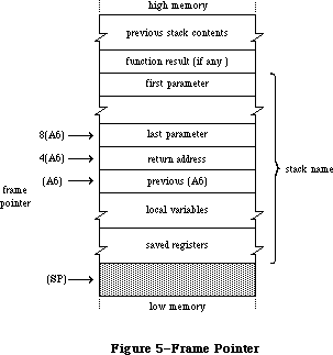 Figure 5–Frame Pointer
Since the saved contents of the frame pointer register occupy a long word (four bytes) on the stack, the return address is located at 4(A6) and the last parameter at 8(A6). This is followed by the rest of the parameters in reverse order, and finally by the space reserved for the function result, if any. The proper offsets for these remaining parameters and for the function result depend on the number and types of the parameters, according to the table above under “Stack Based Routines”. If the LINK instruction allocated stack space for any local variables, they can be accessed at negative offsets from the frame pointer, again depending on their number and types.
At the end of the routine, the instruction
UNLK A6
reverses the process: First it releases the local variables by setting the stack pointer equal to the frame pointer (A6), then it pops the saved contents back into register A6. This restores the register to its original state and leaves the stack pointer pointing to the routine’s return address.
A routine with no parameters can now just return to the caller with an RTS instruction. But if there are any parameters, it’s the routine’s responsibility to pop them from the stack before returning. The usual way of doing this is to pop the return address into an address register, increment the stack pointer to remove the parameters, and then exit with an indirect jump through the register.
Remember that any routine called from Pascal must preserve registers A2-A6 and D3-D7. This is usually done by saving the registers that the routine will be using on the stack with a MOVEM instruction, and then restoring them before returning. Any routine you write that will be accessed via the trap mechanism - for instance, your own version of a Toolbox or Operating System routine that you’ve patched into the trap dispatch table - should observe the same conventions.
Putting all this together, the routine should begin with a sequence like
MyRoutine LINK A6,#-dd ;set up frame pointer--
; dd = number of bytes
; of local variables
MOVEM.L A2-A4/D3-D7,-(SP) ;...or whatever
; registers you use
and end with something like
MOVEM.L (SP)+,A2-A4/D3-D7 ;restore registers
UNLK A6 ;restore frame pointer
MOVE.L (SP)+,A1 ;save return address in an
; available register
ADD.W #pp,SP ;pop parameters--
; pp = number of bytes
; of parameters
JMP (A1) ;return to caller
Notice that A6 doesn’t have to be included in the MOVEM instructions, since
it’s saved and restored by the LINK and UNLK.
_______________________________________________________________________________
»SUMMARY
_______________________________________________________________________________
Variables
OneOne $00010001
MinusOne $FFFFFFFF
Lo3Bytes $00FFFFFF
Scratch20 20-byte scratch area
Scratch8 8-byte scratch area
ToolScratch 8-byte scratch area
ApplScratch 12-byte scratch area reserved for use by applications
ROMBase Base address of ROM
RAMBase Trap dispatch table's base address for routines in RAM
CurrentA5 Address of boundary between application globals
and application parameters
Further Reference:
_______________________________________________________________________________
Technical Note #21, QuickDraw’s Internal Picture Definition
Technical Note #88, Signals
Technical Note #103, MaxApplZone & MoveHHi from Assembly Language
Technical Note #156, Checking for Specific Functionality
Technical Note #164, MPW C Functions: To declare or not to declare…
Figure 5–Frame Pointer
Since the saved contents of the frame pointer register occupy a long word (four bytes) on the stack, the return address is located at 4(A6) and the last parameter at 8(A6). This is followed by the rest of the parameters in reverse order, and finally by the space reserved for the function result, if any. The proper offsets for these remaining parameters and for the function result depend on the number and types of the parameters, according to the table above under “Stack Based Routines”. If the LINK instruction allocated stack space for any local variables, they can be accessed at negative offsets from the frame pointer, again depending on their number and types.
At the end of the routine, the instruction
UNLK A6
reverses the process: First it releases the local variables by setting the stack pointer equal to the frame pointer (A6), then it pops the saved contents back into register A6. This restores the register to its original state and leaves the stack pointer pointing to the routine’s return address.
A routine with no parameters can now just return to the caller with an RTS instruction. But if there are any parameters, it’s the routine’s responsibility to pop them from the stack before returning. The usual way of doing this is to pop the return address into an address register, increment the stack pointer to remove the parameters, and then exit with an indirect jump through the register.
Remember that any routine called from Pascal must preserve registers A2-A6 and D3-D7. This is usually done by saving the registers that the routine will be using on the stack with a MOVEM instruction, and then restoring them before returning. Any routine you write that will be accessed via the trap mechanism - for instance, your own version of a Toolbox or Operating System routine that you’ve patched into the trap dispatch table - should observe the same conventions.
Putting all this together, the routine should begin with a sequence like
MyRoutine LINK A6,#-dd ;set up frame pointer--
; dd = number of bytes
; of local variables
MOVEM.L A2-A4/D3-D7,-(SP) ;...or whatever
; registers you use
and end with something like
MOVEM.L (SP)+,A2-A4/D3-D7 ;restore registers
UNLK A6 ;restore frame pointer
MOVE.L (SP)+,A1 ;save return address in an
; available register
ADD.W #pp,SP ;pop parameters--
; pp = number of bytes
; of parameters
JMP (A1) ;return to caller
Notice that A6 doesn’t have to be included in the MOVEM instructions, since
it’s saved and restored by the LINK and UNLK.
_______________________________________________________________________________
»SUMMARY
_______________________________________________________________________________
Variables
OneOne $00010001
MinusOne $FFFFFFFF
Lo3Bytes $00FFFFFF
Scratch20 20-byte scratch area
Scratch8 8-byte scratch area
ToolScratch 8-byte scratch area
ApplScratch 12-byte scratch area reserved for use by applications
ROMBase Base address of ROM
RAMBase Trap dispatch table's base address for routines in RAM
CurrentA5 Address of boundary between application globals
and application parameters
Further Reference:
_______________________________________________________________________________
Technical Note #21, QuickDraw’s Internal Picture Definition
Technical Note #88, Signals
Technical Note #103, MaxApplZone & MoveHHi from Assembly Language
Technical Note #156, Checking for Specific Functionality
Technical Note #164, MPW C Functions: To declare or not to declare…
QuickDraw
_______________________________________________________________________________
QUICKDRAW
_______________________________________________________________________________
About This Chapter
About QuickDraw
The Mathematical Foundation of QuickDraw
The Coordinate Plane
Points
Rectangles
Regions
Graphic Entities
Bit Images
Bit Maps
Patterns
Cursors
Graphic Entities as Resources
The Drawing Environment: GrafPort
Pen Characteristics
Text Characteristics
Coordinates in GrafPorts
General Discussion of Drawing
Transfer Modes
Drawing in Color
Pictures and Polygons
Pictures
Polygons
Using QuickDraw
QuickDraw Routines
GrafPort Routines
Cursor-Handling Routines
Pen and Line-Drawing Routines
Text-Drawing Routines
Drawing in Color
Calculations with Rectangles
Graphic Operations on Rectangles
Graphic Operations on Ovals
Graphic Operations on Rounded-Corner Rectangles
Graphic Operations on Arcs and Wedges
Calculations with Regions
Graphic Operations on Regions
Bit Map Operations
Pictures
Calculations with Polygons
Graphic Operations on Polygons
Calculations with Points
Miscellaneous Routines
Advanced Routine
Customizing QuickDraw Operations
Summary of QuickDraw
_______________________________________________________________________________
»ABOUT THIS CHAPTER
_______________________________________________________________________________
This chapter describes QuickDraw, the part of the Toolbox that allows Macintosh programmers to perform highly complex graphic operations very easily and very quickly. It describes the data types used by QuickDraw and gives details of the procedures and functions available in QuickDraw.
_______________________________________________________________________________
»ABOUT QUICKDRAW
_______________________________________________________________________________
QuickDraw allows you to draw many different things on the Macintosh screen; some of these are illustrated in Figure 1.
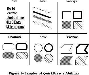 Figure 1–Samples of QuickDraw’s Abilities
You can draw:
• text characters in a number of proportionally-spaced fonts, with
variations that include boldfacing, italicizing, underlining, and
outlining
• straight lines of any length, width, and pattern
• a variety of shapes, including rectangles, rounded-corner rectangles,
circles and ovals, and polygons, all either outlined and hollow or
filled in with a pattern
• arcs of ovals, or wedge-shaped sections filled in with a pattern
• any other arbitrary shape or collection of shapes
• a picture composed of any combination of the above, drawn with just
a single procedure call
QuickDraw also has some other abilities that you won’t find in many other graphics packages. These abilities take care of most of the “housekeeping”—the trivial but time-consuming overhead that’s necessary to keep things in order. They include:
• The ability to define many distinct “ports” on the screen. Each port
has its own complete drawing environment—its own coordinate system,
drawing location, character set, location on the screen, and so on.
You can easily switch from one drawing port to another.
• Full and complete “clipping” to arbitrary areas, so that drawing will
occur only where you want. It’s like an electronic coloring book that
won’t let you color outside the lines. You don’t have to worry about
accidentally drawing over something else on the screen, or drawing off
the screen and destroying memory.
• Off-screen drawing. Anything you can draw on the screen, you can also
draw into an off-screen buffer, so you can prepare an image for an
output device without disturbing the screen, or you can prepare a
picture and move it onto the screen very quickly.
And QuickDraw lives up to its name: It’s very fast. The speed and responsiveness of the Macintosh user interface are due primarily to the speed of QuickDraw. You can do good-quality animation, fast interactive graphics, and complex yet speedy text displays using the full features of QuickDraw. This means you don’t have to bypass the general-purpose QuickDraw routines by writing a lot of special routines to improve speed.
In addition to its routines and data types, QuickDraw provides global variables that you can use from your Pascal program. For example, there’s a variable named thePort that points to the current drawing port.
Assembly-language note: See the discussion of InitGraf in the “QuickDraw
Routines” section for details on how to access the
QuickDraw global variables from assembly language.
In conjunction with the Font Manager, QuickDraw supports font families, fractional character widths, and the disabling of font scaling; these features are described in the Font Manager chapter section.
The 128K ROM version of QuickDraw supports all eight transfer modes for text drawing, instead of just srcOr, srcBic, and scrXor.
The size of a picture is a long word with a range of over four gigabytes. To get the size of a picture, use GetHandleSize instead of looking at the picSize field, which for compatibility contains the low 16 bits of the real size. Old code will work fine for pictures up to 32767 bytes. To check whether you have run out of memory during picture creation, test EmptyRect(picFrame); it returns TRUE if you have.
The following bugs have been fixed in the 128K ROM:
• RectInRgn used to return TRUE occasionally when the rectangle intersected
the region’s enclosing rectangle but not the actual region.
• SectRgn, DiffRgn, UnionRgn, XorRgn, and FrameRgn used to cause a stack
overflow for regions with more than 25 rectangles in one scan line.
• PtToAngle didn’t work correctly when the angle was 90 and the aspect
ratio was a power of two.
• In some cases where the CopyBits source bitmap overlapped its destination,
the transfer would destroy the source bitmap before it was used.
• If you tried to draw a long piece of shadowed text with a tall font,
QuickDraw would cause a stack overflow if there wasn’t enough stack
space for the required off-screen buffer. Now it detects the potential
stack overflow and recurses on the left and right halves of the text.
• DrawText did not work correctly in pictures if the character count
was greater than 255.
The original QuickDraw described in this chapter has been expanded in two significant areas: color capabilities with Color QuickDraw, which gives each pixel color information, and direct RGB colors with 32-Bit QuickDraw, where every pixel can contain a full RGB record with up to eight bits per component. Refer to the Color QuickDraw chapter and the 32-Bit QuickDraw documentation for more details on both of these enhancements to QuickDraw.
_______________________________________________________________________________
»THE MATHEMATICAL FOUNDATION OF QUICKDRAW
_______________________________________________________________________________
To create graphics that are both precise and pretty requires not supercharged features but a firm mathematical foundation for the features you have. If the mathematics that underlie a graphics package are imprecise or fuzzy, the graphics will be, too. QuickDraw defines some clear mathematical constructs that are widely used in its procedures, functions, and data types: the coordinate plane, the point, the rectangle, and the region.
_______________________________________________________________________________
»The Coordinate Plane
All information about location or movement is given to QuickDraw in terms of coordinates on a plane. The coordinate plane is a two-dimensional grid, as illustrated in Figure 2.
Note the following features of the QuickDraw coordinate plane:
• All grid coordinates are integers (in the range –32767 to 32767).
• All grid lines are infinitely thin.
Figure 1–Samples of QuickDraw’s Abilities
You can draw:
• text characters in a number of proportionally-spaced fonts, with
variations that include boldfacing, italicizing, underlining, and
outlining
• straight lines of any length, width, and pattern
• a variety of shapes, including rectangles, rounded-corner rectangles,
circles and ovals, and polygons, all either outlined and hollow or
filled in with a pattern
• arcs of ovals, or wedge-shaped sections filled in with a pattern
• any other arbitrary shape or collection of shapes
• a picture composed of any combination of the above, drawn with just
a single procedure call
QuickDraw also has some other abilities that you won’t find in many other graphics packages. These abilities take care of most of the “housekeeping”—the trivial but time-consuming overhead that’s necessary to keep things in order. They include:
• The ability to define many distinct “ports” on the screen. Each port
has its own complete drawing environment—its own coordinate system,
drawing location, character set, location on the screen, and so on.
You can easily switch from one drawing port to another.
• Full and complete “clipping” to arbitrary areas, so that drawing will
occur only where you want. It’s like an electronic coloring book that
won’t let you color outside the lines. You don’t have to worry about
accidentally drawing over something else on the screen, or drawing off
the screen and destroying memory.
• Off-screen drawing. Anything you can draw on the screen, you can also
draw into an off-screen buffer, so you can prepare an image for an
output device without disturbing the screen, or you can prepare a
picture and move it onto the screen very quickly.
And QuickDraw lives up to its name: It’s very fast. The speed and responsiveness of the Macintosh user interface are due primarily to the speed of QuickDraw. You can do good-quality animation, fast interactive graphics, and complex yet speedy text displays using the full features of QuickDraw. This means you don’t have to bypass the general-purpose QuickDraw routines by writing a lot of special routines to improve speed.
In addition to its routines and data types, QuickDraw provides global variables that you can use from your Pascal program. For example, there’s a variable named thePort that points to the current drawing port.
Assembly-language note: See the discussion of InitGraf in the “QuickDraw
Routines” section for details on how to access the
QuickDraw global variables from assembly language.
In conjunction with the Font Manager, QuickDraw supports font families, fractional character widths, and the disabling of font scaling; these features are described in the Font Manager chapter section.
The 128K ROM version of QuickDraw supports all eight transfer modes for text drawing, instead of just srcOr, srcBic, and scrXor.
The size of a picture is a long word with a range of over four gigabytes. To get the size of a picture, use GetHandleSize instead of looking at the picSize field, which for compatibility contains the low 16 bits of the real size. Old code will work fine for pictures up to 32767 bytes. To check whether you have run out of memory during picture creation, test EmptyRect(picFrame); it returns TRUE if you have.
The following bugs have been fixed in the 128K ROM:
• RectInRgn used to return TRUE occasionally when the rectangle intersected
the region’s enclosing rectangle but not the actual region.
• SectRgn, DiffRgn, UnionRgn, XorRgn, and FrameRgn used to cause a stack
overflow for regions with more than 25 rectangles in one scan line.
• PtToAngle didn’t work correctly when the angle was 90 and the aspect
ratio was a power of two.
• In some cases where the CopyBits source bitmap overlapped its destination,
the transfer would destroy the source bitmap before it was used.
• If you tried to draw a long piece of shadowed text with a tall font,
QuickDraw would cause a stack overflow if there wasn’t enough stack
space for the required off-screen buffer. Now it detects the potential
stack overflow and recurses on the left and right halves of the text.
• DrawText did not work correctly in pictures if the character count
was greater than 255.
The original QuickDraw described in this chapter has been expanded in two significant areas: color capabilities with Color QuickDraw, which gives each pixel color information, and direct RGB colors with 32-Bit QuickDraw, where every pixel can contain a full RGB record with up to eight bits per component. Refer to the Color QuickDraw chapter and the 32-Bit QuickDraw documentation for more details on both of these enhancements to QuickDraw.
_______________________________________________________________________________
»THE MATHEMATICAL FOUNDATION OF QUICKDRAW
_______________________________________________________________________________
To create graphics that are both precise and pretty requires not supercharged features but a firm mathematical foundation for the features you have. If the mathematics that underlie a graphics package are imprecise or fuzzy, the graphics will be, too. QuickDraw defines some clear mathematical constructs that are widely used in its procedures, functions, and data types: the coordinate plane, the point, the rectangle, and the region.
_______________________________________________________________________________
»The Coordinate Plane
All information about location or movement is given to QuickDraw in terms of coordinates on a plane. The coordinate plane is a two-dimensional grid, as illustrated in Figure 2.
Note the following features of the QuickDraw coordinate plane:
• All grid coordinates are integers (in the range –32767 to 32767).
• All grid lines are infinitely thin.
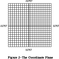 Figure 2–The Coordinate Plane
These concepts are important. First, they mean that the QuickDraw plane is finite, not infinite (although it’s very large). Second, they mean that all elements represented on the coordinate plane are mathematically pure. Mathematical calculations using integer arithmetic will produce intuitively correct results. If you keep in mind that grid lines are infinitely thin,
you’ll never have “endpoint paranoia”—the confusion that results from not knowing whether that last dot is included in the line.
_______________________________________________________________________________
»Points
There are 4,294,836,224 unique points on the coordinate plane. Each point is at the intersection of a horizontal grid line and a vertical grid line. As the grid lines are infinitely thin, so a point is infinitely small. Of course, there are many more points on this grid than there are dots on the Macintosh screen: When using QuickDraw you associate small parts of the grid with areas on the screen, so that you aren’t bound into an arbitrary, limited coordinate system.
The coordinate origin (0,0) is in the middle of the grid. Horizontal coordinates increase as you move from left to right, and vertical coordinates increase as you move from top to bottom. This is the way both a TV screen and a page of English text are scanned: from the top left to the bottom right.
Figure 3 shows the relationship between points, grid lines, and pixels, the physical dots on the screen. (Pixels correspond to bits in memory, as described in the next section.)
You can store the coordinates of a point into a Pascal variable of type Point, defined by QuickDraw as a record of two integers:
TYPE VHSelect = (v,h);
Point = RECORD CASE INTEGER OF
0: (v: INTEGER: {vertical coordinate}
h: INTEGER); {horizontal coordinate}
1: (vh: ARRAY[VHSelect] OF INTEGER)
END;
Figure 2–The Coordinate Plane
These concepts are important. First, they mean that the QuickDraw plane is finite, not infinite (although it’s very large). Second, they mean that all elements represented on the coordinate plane are mathematically pure. Mathematical calculations using integer arithmetic will produce intuitively correct results. If you keep in mind that grid lines are infinitely thin,
you’ll never have “endpoint paranoia”—the confusion that results from not knowing whether that last dot is included in the line.
_______________________________________________________________________________
»Points
There are 4,294,836,224 unique points on the coordinate plane. Each point is at the intersection of a horizontal grid line and a vertical grid line. As the grid lines are infinitely thin, so a point is infinitely small. Of course, there are many more points on this grid than there are dots on the Macintosh screen: When using QuickDraw you associate small parts of the grid with areas on the screen, so that you aren’t bound into an arbitrary, limited coordinate system.
The coordinate origin (0,0) is in the middle of the grid. Horizontal coordinates increase as you move from left to right, and vertical coordinates increase as you move from top to bottom. This is the way both a TV screen and a page of English text are scanned: from the top left to the bottom right.
Figure 3 shows the relationship between points, grid lines, and pixels, the physical dots on the screen. (Pixels correspond to bits in memory, as described in the next section.)
You can store the coordinates of a point into a Pascal variable of type Point, defined by QuickDraw as a record of two integers:
TYPE VHSelect = (v,h);
Point = RECORD CASE INTEGER OF
0: (v: INTEGER: {vertical coordinate}
h: INTEGER); {horizontal coordinate}
1: (vh: ARRAY[VHSelect] OF INTEGER)
END;
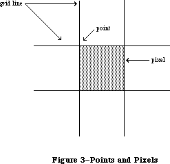 Figure 3–Points and Pixels
The variant part of this record lets you access the vertical and horizontal coordinates of a point either individually or as an array. For example, if the variable goodPt is declared to be of type Point, the following will all refer to the coordinates of the point:
goodPt.v goodPt.h
goodPt.vh[v] goodPt.vh[h]
_______________________________________________________________________________
»Rectangles
Any two points can define the top left and bottom right corners of a rectangle. As these points are infinitely small, the borders of the rectangle are infinitely thin (see Figure 4).
Figure 3–Points and Pixels
The variant part of this record lets you access the vertical and horizontal coordinates of a point either individually or as an array. For example, if the variable goodPt is declared to be of type Point, the following will all refer to the coordinates of the point:
goodPt.v goodPt.h
goodPt.vh[v] goodPt.vh[h]
_______________________________________________________________________________
»Rectangles
Any two points can define the top left and bottom right corners of a rectangle. As these points are infinitely small, the borders of the rectangle are infinitely thin (see Figure 4).
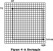 Figure 4–A Rectangle
Rectangles are used to define active areas on the screen, to assign coordinate systems to graphic entities, and to specify the locations and sizes for various drawing commands. QuickDraw also allows you to perform many mathematical calculations on rectangles—changing their sizes, shifting them around, and so on.
Note: Remember that rectangles, like points, are mathematical concepts
that have no direct representation on the screen. The association
between these conceptual elements and their physical representations
is made by the BitMap data type, described in the following section.
The data type for rectangles is called Rect, and consists of four integers or two points:
TYPE Rect = RECORD CASE INTEGER OF
0: (top: INTEGER;
left: INTEGER;
bottom: INTEGER;
right: INTEGER);
1: (topLeft: Point;
botRight: Point)
END;
Again, the record variant allows you to access a variable of type Rect either as four boundary coordinates or as two diagonally opposite corner points. Combined with the record variant for points, all of the following references to the rectangle named aRect are legal:
aRect {type Rect}
aRect.topLeft aRect.botRight {type Point}
aRect.top aRect.left {type INTEGER}
aRect.topLeft.v aRect.topLeft.h {type INTEGER}
aRect.topLeft.vh[v] aRect.topLeft.vh[h] {type INTEGER}
aRect.bottom aRect.right {type INTEGER}
aRect.botRight.v aRect.botRight.h {type INTEGER}
aRect.botRight.vh[v] aRect.botRight.vh[h] {type INTEGER}
Note: If the bottom coordinate of a rectangle is equal to or less than
the top, or the right coordinate is equal to or less than the left,
the rectangle is an empty rectangle (that is, one that contains no bits).
_______________________________________________________________________________
»Regions
Unlike most graphics packages that can manipulate only simple geometric structures (usually rectilinear, at that), QuickDraw has the ability to gather an arbitrary set of spatially coherent points into a structure called a region, and perform complex yet rapid manipulations and calculations on such structures. Regions not only make your programs simpler and faster, but will let you perform operations that would otherwise be nearly impossible.
You define a region by calling routines that draw lines and shapes (even other regions). The outline of a region should be one or more closed loops. A region can be concave or convex, can consist of one area or many disjoint areas, and can even have “holes” in the middle. In Figure 5, the region on the left has a hole in the middle, and the region on the right consists of two disjoint areas.
Figure 4–A Rectangle
Rectangles are used to define active areas on the screen, to assign coordinate systems to graphic entities, and to specify the locations and sizes for various drawing commands. QuickDraw also allows you to perform many mathematical calculations on rectangles—changing their sizes, shifting them around, and so on.
Note: Remember that rectangles, like points, are mathematical concepts
that have no direct representation on the screen. The association
between these conceptual elements and their physical representations
is made by the BitMap data type, described in the following section.
The data type for rectangles is called Rect, and consists of four integers or two points:
TYPE Rect = RECORD CASE INTEGER OF
0: (top: INTEGER;
left: INTEGER;
bottom: INTEGER;
right: INTEGER);
1: (topLeft: Point;
botRight: Point)
END;
Again, the record variant allows you to access a variable of type Rect either as four boundary coordinates or as two diagonally opposite corner points. Combined with the record variant for points, all of the following references to the rectangle named aRect are legal:
aRect {type Rect}
aRect.topLeft aRect.botRight {type Point}
aRect.top aRect.left {type INTEGER}
aRect.topLeft.v aRect.topLeft.h {type INTEGER}
aRect.topLeft.vh[v] aRect.topLeft.vh[h] {type INTEGER}
aRect.bottom aRect.right {type INTEGER}
aRect.botRight.v aRect.botRight.h {type INTEGER}
aRect.botRight.vh[v] aRect.botRight.vh[h] {type INTEGER}
Note: If the bottom coordinate of a rectangle is equal to or less than
the top, or the right coordinate is equal to or less than the left,
the rectangle is an empty rectangle (that is, one that contains no bits).
_______________________________________________________________________________
»Regions
Unlike most graphics packages that can manipulate only simple geometric structures (usually rectilinear, at that), QuickDraw has the ability to gather an arbitrary set of spatially coherent points into a structure called a region, and perform complex yet rapid manipulations and calculations on such structures. Regions not only make your programs simpler and faster, but will let you perform operations that would otherwise be nearly impossible.
You define a region by calling routines that draw lines and shapes (even other regions). The outline of a region should be one or more closed loops. A region can be concave or convex, can consist of one area or many disjoint areas, and can even have “holes” in the middle. In Figure 5, the region on the left has a hole in the middle, and the region on the right consists of two disjoint areas.
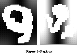 Figure 5–Regions
The data structure for a region consists of two fixed-length fields followed by a variable-length field:
TYPE Region = RECORD
rgnSize: INTEGER; {size in bytes}
rgnBBox: Rect; {enclosing rectangle}
{more data if not rectangular}
END;
The rgnSize field contains the size, in bytes, of the region variable. The maximum size of a region is 32K bytes. The rgnBBox field is a rectangle that completely encloses the region.
The simplest region is a rectangle. In this case, the rgnBBox field defines the entire region, and there’s no optional region data. For rectangular regions (or empty regions), the rgnSize field contains 10.
The region definition data for nonrectangular regions is stored in a compact way that allows for highly efficient access by QuickDraw routines.
All regions are accessed through handles:
TYPE RgnPtr = ^Region;
RgnHandle = ^RgnPtr;
Many calculations can be performed on regions. A region can be “expanded” or
“shrunk” and, given any two regions, QuickDraw can find their union, intersection, difference, and exclusive-OR; it can also determine whether a given point intersects a region, and so on.
_______________________________________________________________________________
»GRAPHIC ENTITIES
_______________________________________________________________________________
Points, rectangles, and regions are all mathematical models rather than actual graphic elements—they’re data types that QuickDraw uses for drawing, but they don’t actually appear on the screen. Some entities that do have a direct graphic interpretation are the bit image, bit map, pattern, and cursor. This section describes these graphic entities and relates them to the mathematical constructs described above.
_______________________________________________________________________________
»Bit Images
A bit image is a collection of bits in memory that have a rectilinear representation. Take a collection of words in memory and lay them end to end so that bit 15 of the lowest-numbered word is on the left and bit 0 of the highest-numbered word is on the far right. Then take this array of bits and divide it, on word boundaries, into a number of equal-size rows. Stack these rows vertically so that the first row is on the top and the last row is on the bottom. The result is a matrix like the one shown in Figure 6—rows and columns of bits, with each row containing the same number of bytes. The number of bytes in each row of the bit image is called the row width of that image. A bit image can be any length that’s a multiple of the row width.
Figure 5–Regions
The data structure for a region consists of two fixed-length fields followed by a variable-length field:
TYPE Region = RECORD
rgnSize: INTEGER; {size in bytes}
rgnBBox: Rect; {enclosing rectangle}
{more data if not rectangular}
END;
The rgnSize field contains the size, in bytes, of the region variable. The maximum size of a region is 32K bytes. The rgnBBox field is a rectangle that completely encloses the region.
The simplest region is a rectangle. In this case, the rgnBBox field defines the entire region, and there’s no optional region data. For rectangular regions (or empty regions), the rgnSize field contains 10.
The region definition data for nonrectangular regions is stored in a compact way that allows for highly efficient access by QuickDraw routines.
All regions are accessed through handles:
TYPE RgnPtr = ^Region;
RgnHandle = ^RgnPtr;
Many calculations can be performed on regions. A region can be “expanded” or
“shrunk” and, given any two regions, QuickDraw can find their union, intersection, difference, and exclusive-OR; it can also determine whether a given point intersects a region, and so on.
_______________________________________________________________________________
»GRAPHIC ENTITIES
_______________________________________________________________________________
Points, rectangles, and regions are all mathematical models rather than actual graphic elements—they’re data types that QuickDraw uses for drawing, but they don’t actually appear on the screen. Some entities that do have a direct graphic interpretation are the bit image, bit map, pattern, and cursor. This section describes these graphic entities and relates them to the mathematical constructs described above.
_______________________________________________________________________________
»Bit Images
A bit image is a collection of bits in memory that have a rectilinear representation. Take a collection of words in memory and lay them end to end so that bit 15 of the lowest-numbered word is on the left and bit 0 of the highest-numbered word is on the far right. Then take this array of bits and divide it, on word boundaries, into a number of equal-size rows. Stack these rows vertically so that the first row is on the top and the last row is on the bottom. The result is a matrix like the one shown in Figure 6—rows and columns of bits, with each row containing the same number of bytes. The number of bytes in each row of the bit image is called the row width of that image. A bit image can be any length that’s a multiple of the row width.
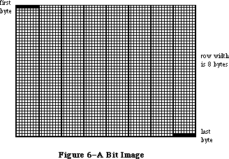 Figure 6–A Bit Image
The screen itself is one large visible bit image. On a Macintosh 128K or 512K, for example, the screen is a 342-by-512 bit image, with a row width of 64 bytes. These 21,888 bytes of memory are displayed as a matrix of 175,104 pixels on the screen, each bit corresponding to one pixel. If a bit’s value is 0, its pixel is white; if the bit’s value is 1, the pixel is black.
Warning: The numbers given here apply only to the Macintosh 128K and 512K
systems. To allow for your application running on any version of
the Macintosh, you should never use explicit numbers for screen
dimensions. The QuickDraw global variable screenBits (a bit map,
described below) gives you access to a rectangle whose dimensions
are those of the main screen, whatever version of the Macintosh is
being used.
On a Macintosh 128K or 512K, each pixel on the screen is square, and there are 72 pixels per inch in each direction. On an unmodified Macintosh XL, each pixel is one and a half times taller than it is wide, meaning a rectangle 30 pixels wide by 20 tall looks square; there are 90 pixels per inch horizontally, and 60 per inch vertically. A Macintosh XL may be modified to have square pixels. You can get the the screen resolution by calling the Toolbox Utility procedure ScreenRes.
Note: The values given for pixels per inch may not be exactly the measurement
on the screen, but they’re the values you should use when calculating
the size of printed output.
Note: Since each pixel on the screen represents one bit in a bit image,
wherever this chapter says “bit”, you can substitute “pixel” if the
bit image is the screen. Likewise, this chapter often refers to pixels
on the screen where the discussion applies equally to bits in an off-
screen bit image.
_______________________________________________________________________________
»Bit Maps
A bit map in QuickDraw is a data structure that defines a physical bit image in terms of the coordinate plane. A bit map has three parts: a pointer to a bit image, the row width of that image, and a boundary rectangle that gives the bit map both its dimensions and a coordinate system.
There can be several bit maps pointing to the same bit image, each imposing a different coordinate system on it. This important feature is explained in
“Coordinates in GrafPorts”, below.
As shown in Figure 7, the structure of a bit map is as follows:
TYPE BitMap = RECORD
baseAddr: Ptr; {pointer to bit image}
rowBytes: INTEGER; {row width}
bounds: Rect {boundary rectangle}
END;
Figure 6–A Bit Image
The screen itself is one large visible bit image. On a Macintosh 128K or 512K, for example, the screen is a 342-by-512 bit image, with a row width of 64 bytes. These 21,888 bytes of memory are displayed as a matrix of 175,104 pixels on the screen, each bit corresponding to one pixel. If a bit’s value is 0, its pixel is white; if the bit’s value is 1, the pixel is black.
Warning: The numbers given here apply only to the Macintosh 128K and 512K
systems. To allow for your application running on any version of
the Macintosh, you should never use explicit numbers for screen
dimensions. The QuickDraw global variable screenBits (a bit map,
described below) gives you access to a rectangle whose dimensions
are those of the main screen, whatever version of the Macintosh is
being used.
On a Macintosh 128K or 512K, each pixel on the screen is square, and there are 72 pixels per inch in each direction. On an unmodified Macintosh XL, each pixel is one and a half times taller than it is wide, meaning a rectangle 30 pixels wide by 20 tall looks square; there are 90 pixels per inch horizontally, and 60 per inch vertically. A Macintosh XL may be modified to have square pixels. You can get the the screen resolution by calling the Toolbox Utility procedure ScreenRes.
Note: The values given for pixels per inch may not be exactly the measurement
on the screen, but they’re the values you should use when calculating
the size of printed output.
Note: Since each pixel on the screen represents one bit in a bit image,
wherever this chapter says “bit”, you can substitute “pixel” if the
bit image is the screen. Likewise, this chapter often refers to pixels
on the screen where the discussion applies equally to bits in an off-
screen bit image.
_______________________________________________________________________________
»Bit Maps
A bit map in QuickDraw is a data structure that defines a physical bit image in terms of the coordinate plane. A bit map has three parts: a pointer to a bit image, the row width of that image, and a boundary rectangle that gives the bit map both its dimensions and a coordinate system.
There can be several bit maps pointing to the same bit image, each imposing a different coordinate system on it. This important feature is explained in
“Coordinates in GrafPorts”, below.
As shown in Figure 7, the structure of a bit map is as follows:
TYPE BitMap = RECORD
baseAddr: Ptr; {pointer to bit image}
rowBytes: INTEGER; {row width}
bounds: Rect {boundary rectangle}
END;
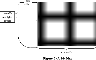 Figure 7–A Bit Map
BaseAddr is a pointer to the beginning of the bit image in memory. RowBytes is the row width in bytes. Both of these must always be even: A bit map must always begin on a word boundary and contain an integral number of words in each row.
The bounds field is the bit map’s boundary rectangle, which both encloses the active area of the bit image and imposes a coordinate system on it. The top left corner of the boundary rectangle is aligned around the first bit in the bit image.
The relationship between the boundary rectangle and the bit image in a bit map is simple yet very important. First, some general rules:
• Bits in a bit image fall between points on the coordinate plane.
• A rectangle that is H points wide and V points tall encloses
exactly (H–1)*(V–1) bits.
The coordinate system assigns integer values to the lines that border and separate bits, not to the bit positions themselves. For example, if a bit map is assigned the boundary rectangle with corners (10,–8) and (34,8), the bottom right bit in the image will be between horizontal coordinates 33 and 34, and between vertical coordinates 7 and 8 (see Figure 8).
Figure 7–A Bit Map
BaseAddr is a pointer to the beginning of the bit image in memory. RowBytes is the row width in bytes. Both of these must always be even: A bit map must always begin on a word boundary and contain an integral number of words in each row.
The bounds field is the bit map’s boundary rectangle, which both encloses the active area of the bit image and imposes a coordinate system on it. The top left corner of the boundary rectangle is aligned around the first bit in the bit image.
The relationship between the boundary rectangle and the bit image in a bit map is simple yet very important. First, some general rules:
• Bits in a bit image fall between points on the coordinate plane.
• A rectangle that is H points wide and V points tall encloses
exactly (H–1)*(V–1) bits.
The coordinate system assigns integer values to the lines that border and separate bits, not to the bit positions themselves. For example, if a bit map is assigned the boundary rectangle with corners (10,–8) and (34,8), the bottom right bit in the image will be between horizontal coordinates 33 and 34, and between vertical coordinates 7 and 8 (see Figure 8).
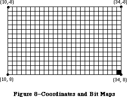 Figure 8–Coordinates and Bit Maps
The width of the boundary rectangle determines how many bits of one row are logically owned by the bit map. This width must not exceed the number of bits in each row of the bit image. The height of the boundary rectangle determines how many rows of the image are logically owned by the bit map. The number of rows enclosed by the boundary rectangle must not exceed the number of rows in the bit image.
Normally, the boundary rectangle completely encloses the bit image. If the rectangle is smaller than the dimensions of the image, the least significant bits in each row, as well as the last rows in the image, aren’t affected by any operations on the bit map.
There’s a QuickDraw global variable, named screenBits, that contains a bit map corresponding to the screen of the Macintosh being used. Wherever your program needs the exact dimensions of the screen, it should get them from the boundary rectangle of this variable.
_______________________________________________________________________________
»Patterns
A pattern is a 64-bit image, organized as an 8-by-8-bit square, that’s used to define a repeating design (such as stripes) or tone (such as gray). Patterns can be used to draw lines and shapes or to fill areas on the screen.
When a pattern is drawn, it’s aligned so that adjacent areas of the same pattern in the same graphics port will blend with it into a continuous, coordinated pattern. QuickDraw provides predefined patterns in global variables named white, black, gray, ltGray, and dkGray. Any other 64-bit variable or constant can also be used as a pattern. The data type definition for a pattern is as follows:
TYPE Pattern = PACKED ARRAY[0..7] OF 0..255;
The row width of a pattern is one byte.
_______________________________________________________________________________
»Cursors
A cursor is a small image that appears on the screen and is controlled by the mouse. (It appears only on the screen, and never in an off-screen bit image.)
Note: Macintosh user manuals call this image a “pointer”, since it points
to a location on the screen. To avoid confusion with other meanings
of “pointer” in Inside Macintosh, we use the alternate term “cursor”.
A cursor is defined as a 256-bit image, a 16-by-16-bit square. The row width of a cursor is two bytes. Figure 9 illustrates four cursors.
Figure 8–Coordinates and Bit Maps
The width of the boundary rectangle determines how many bits of one row are logically owned by the bit map. This width must not exceed the number of bits in each row of the bit image. The height of the boundary rectangle determines how many rows of the image are logically owned by the bit map. The number of rows enclosed by the boundary rectangle must not exceed the number of rows in the bit image.
Normally, the boundary rectangle completely encloses the bit image. If the rectangle is smaller than the dimensions of the image, the least significant bits in each row, as well as the last rows in the image, aren’t affected by any operations on the bit map.
There’s a QuickDraw global variable, named screenBits, that contains a bit map corresponding to the screen of the Macintosh being used. Wherever your program needs the exact dimensions of the screen, it should get them from the boundary rectangle of this variable.
_______________________________________________________________________________
»Patterns
A pattern is a 64-bit image, organized as an 8-by-8-bit square, that’s used to define a repeating design (such as stripes) or tone (such as gray). Patterns can be used to draw lines and shapes or to fill areas on the screen.
When a pattern is drawn, it’s aligned so that adjacent areas of the same pattern in the same graphics port will blend with it into a continuous, coordinated pattern. QuickDraw provides predefined patterns in global variables named white, black, gray, ltGray, and dkGray. Any other 64-bit variable or constant can also be used as a pattern. The data type definition for a pattern is as follows:
TYPE Pattern = PACKED ARRAY[0..7] OF 0..255;
The row width of a pattern is one byte.
_______________________________________________________________________________
»Cursors
A cursor is a small image that appears on the screen and is controlled by the mouse. (It appears only on the screen, and never in an off-screen bit image.)
Note: Macintosh user manuals call this image a “pointer”, since it points
to a location on the screen. To avoid confusion with other meanings
of “pointer” in Inside Macintosh, we use the alternate term “cursor”.
A cursor is defined as a 256-bit image, a 16-by-16-bit square. The row width of a cursor is two bytes. Figure 9 illustrates four cursors.
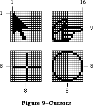 Figure 9–Cursors
A cursor has three fields: a 16-word data field that contains the image itself, a 16-word mask field that contains information about the screen appearance of each bit of the cursor, and a hotSpot point that aligns the cursor with the mouse location.
TYPE Bits16 = ARRAY[0..15] OF INTEGER;
Cursor = RECORD
data: Bits16; {cursor image}
mask: Bits16; {cursor mask}
hotSpot: Point {point aligned with mouse}
END;
The data for the cursor must begin on a word boundary.
The cursor appears on the screen as a 16-by-16-bit square. The appearance of each bit of the square is determined by the corresponding bits in the data and mask and, if the mask bit is 0, by the pixel “under” the cursor (the pixel already on the screen in the same position as this bit of the cursor):
Data Mask Resulting pixel on screen
0 1 White
1 1 Black
0 0 Same as pixel under cursor
1 0 Inverse of pixel under cursor
Notice that if all mask bits are 0, the cursor is completely transparent, in that the image under the cursor can still be viewed: Pixels under the white part of the cursor appear unchanged, while under the black part of the cursor, black pixels show through as white.
The hotSpot aligns a point (not a bit) in the image with the mouse location. Imagine the rectangle with corners (0,0) and (16,16) framing the image, as in each of the examples in Figure 9; the hotSpot is defined in this coordinate system. A hotSpot of (0,0) is at the top left of the image. For the arrow in Figure 9 to point to the mouse location, (1,1) would be its hotSpot. A hotSpot of (8,8) is in the exact center of the image; the center of the plus sign or circle in Figure 9 would coincide with the mouse location if (8,8) were the hotSpot for that cursor. Similarly, the hotSpot for the pointing hand would be
(16,9).
Whenever you move the mouse, the low-level interrupt-driven mouse routines move the cursor’s hotSpot to be aligned with the new mouse location.
QuickDraw supplies a predefined cursor in the global variable named arrow; this is the standard arrow cursor (illustrated in Figure 9).
_______________________________________________________________________________
»Graphic Entities as Resources
You can create cursors and patterns in your program code, but it’s usually simpler and more convenient to store them in a resource file and read them in when you need them. Standard cursors and patterns are available not only through the global variables provided by QuickDraw, but also as system resources stored in the system resource file. QuickDraw itself operates independently of the Resource Manager, so it doesn’t contain routines for accessing graphics-related resources; instead, these routines are included in the Toolbox Utilities (see the Toolbox Utilities chapter for more information).
Besides patterns and cursors, two other graphic entities that may be stored in resource files (and accessed via Toolbox Utility routines) are a QuickDraw picture, described later in this chapter, and an icon, a 32-by-32 bit image that’s used to graphically represent an object, concept, or message.
_______________________________________________________________________________
»THE DRAWING ENVIRONMENT: GRAFPORT
_______________________________________________________________________________
A grafPort is a complete drawing environment that defines where and how graphic operations will take place. You can have many grafPorts open at once, and each one will have its own coordinate system, drawing pattern, background pattern, pen size and location, character font and style, and bit map in which drawing takes place. You can instantly switch from one port to another. GrafPorts are the structures upon which a program builds windows, which are fundamental to the Macintosh “overlapping windows” user interface. Besides being used for windows on the screen, grafPorts are used for printing and for off-screen drawing.
A grafPort is defined as follows:
TYPE GrafPtr = ^GrafPort;
GrafPort = RECORD
device: INTEGER; {device-specific information}
portBits: BitMap; {grafPort's bit map}
portRect: Rect; {grafPort's rectangle}
visRgn: RgnHandle; {visible region}
clipRgn: RgnHandle; {clipping region}
bkPat: Pattern; {background pattern}
fillPat: Pattern; {fill pattern}
pnLoc: Point; {pen location}
pnSize: Point; {pen size}
pnMode: INTEGER; {pen's transfer mode}
pnPat: Pattern; {pen pattern}
pnVis: INTEGER; {pen visibility}
txFont: INTEGER; {font number for text}
txFace: Style; {text's character style}
txMode: INTEGER; {text's transfer mode}
txSize: INTEGER; {font size for text}
spExtra: Fixed; {extra space}
fgColor: LONGINT; {foreground color}
bkColor: LONGINT; {background color}
colrBit: INTEGER; {color bit}
patStretch: INTEGER; {used internally}
picSave: Handle; {picture being saved}
rgnSave: Handle; {region being saved}
polySave: Handle; {polygon being saved}
grafProcs: QDProcsPtr {low-level drawing routines}
END;
Note that picSave is a Handle used internally by QuickDraw while it is saving a picture, and rgnSave and polySave are used by QuickDraw as flags; they are set to “1” when the corresponding action is taking place.
All QuickDraw operations refer to grafPorts via grafPtrs. (For historical reasons, grafPort is one of the few objects in the Macintosh system software that’s referred to by a pointer rather than a handle.)
Warning: You can access all fields and subfields of a grafPort normally,
but you should not store new values directly into them. QuickDraw
has routines for altering all fields of a grafPort, and using
these routines ensures that changing a grafPort produces no
unusual side effects.
The device field of a grafPort contains device-specific information that’s used by the Font Manager to achieve the best possible results when drawing text in the grafPort. There may be physical differences in the same logical font for different output devices, to ensure the highest-quality printing on the device being used. The default value of the device field is 0, for best results on output to the screen. For more information, see the Font Manager chapter.
The portBits field is the bit map that points to the bit image to be used by the grafPort. The default bit map uses the entire screen as its bit image. The bit map may be changed to indicate a different structure in memory: All graphics routines work in exactly the same way regardless of whether their effects are visible on the screen. A program can, for example, prepare an image to be printed on a printer without ever displaying the image on the screen, or develop a picture in an off-screen bit map before transferring it to the screen. The portBits.bounds rectangle determines the coordinate system of the grafPort; all other coordinates in the grafPort are expressed in this system.
The portRect field is a rectangle that defines a subset of the bit map that will be used for drawing: All drawing done by the application occurs inside the portRect. Its coordinates are in the coordinate system defined by the portBits.bounds rectangle. The portRect usually falls within the portBits.bounds rectangle, but it’s not required to do so. The portRect usually defines the “writable” interior area of a window, document, or other object on the screen.
The visRgn field is manipulated by the Window Manager; you will normally never change a grafPort’s visRgn. It indicates the region of the grafPort that’s actually visible on the screen, that is, the part of the window that’s not covered by other windows. For example, if you move one window in front of another, the Window Manager logically removes the area of overlap from the visRgn of the window in back. When you draw into the back window, whatever’s being drawn is clipped to the visRgn so that it doesn’t run over onto the front window. The default visRgn is set to the portRect.
The clipRgn is the grafPort’s clipping region, an arbitrary region that you can use to limit drawing to any region within the portRect. If, for example, you want to draw a half circle on the screen, you can set the clipRgn to half the square that would enclose the whole circle, and then draw the whole circle. Only the half within the clipRgn will actually be drawn in the grafPort. The default clipRgn is set arbitrarily large, you have full control over its setting; as a matter of recommended programming practice, it is advisable to make the default clipRgn rectangle smaller.
Figure 10 illustrates a typical bit map (as defined by portBits), portRect, visRgn, and clipRgn.
Figure 9–Cursors
A cursor has three fields: a 16-word data field that contains the image itself, a 16-word mask field that contains information about the screen appearance of each bit of the cursor, and a hotSpot point that aligns the cursor with the mouse location.
TYPE Bits16 = ARRAY[0..15] OF INTEGER;
Cursor = RECORD
data: Bits16; {cursor image}
mask: Bits16; {cursor mask}
hotSpot: Point {point aligned with mouse}
END;
The data for the cursor must begin on a word boundary.
The cursor appears on the screen as a 16-by-16-bit square. The appearance of each bit of the square is determined by the corresponding bits in the data and mask and, if the mask bit is 0, by the pixel “under” the cursor (the pixel already on the screen in the same position as this bit of the cursor):
Data Mask Resulting pixel on screen
0 1 White
1 1 Black
0 0 Same as pixel under cursor
1 0 Inverse of pixel under cursor
Notice that if all mask bits are 0, the cursor is completely transparent, in that the image under the cursor can still be viewed: Pixels under the white part of the cursor appear unchanged, while under the black part of the cursor, black pixels show through as white.
The hotSpot aligns a point (not a bit) in the image with the mouse location. Imagine the rectangle with corners (0,0) and (16,16) framing the image, as in each of the examples in Figure 9; the hotSpot is defined in this coordinate system. A hotSpot of (0,0) is at the top left of the image. For the arrow in Figure 9 to point to the mouse location, (1,1) would be its hotSpot. A hotSpot of (8,8) is in the exact center of the image; the center of the plus sign or circle in Figure 9 would coincide with the mouse location if (8,8) were the hotSpot for that cursor. Similarly, the hotSpot for the pointing hand would be
(16,9).
Whenever you move the mouse, the low-level interrupt-driven mouse routines move the cursor’s hotSpot to be aligned with the new mouse location.
QuickDraw supplies a predefined cursor in the global variable named arrow; this is the standard arrow cursor (illustrated in Figure 9).
_______________________________________________________________________________
»Graphic Entities as Resources
You can create cursors and patterns in your program code, but it’s usually simpler and more convenient to store them in a resource file and read them in when you need them. Standard cursors and patterns are available not only through the global variables provided by QuickDraw, but also as system resources stored in the system resource file. QuickDraw itself operates independently of the Resource Manager, so it doesn’t contain routines for accessing graphics-related resources; instead, these routines are included in the Toolbox Utilities (see the Toolbox Utilities chapter for more information).
Besides patterns and cursors, two other graphic entities that may be stored in resource files (and accessed via Toolbox Utility routines) are a QuickDraw picture, described later in this chapter, and an icon, a 32-by-32 bit image that’s used to graphically represent an object, concept, or message.
_______________________________________________________________________________
»THE DRAWING ENVIRONMENT: GRAFPORT
_______________________________________________________________________________
A grafPort is a complete drawing environment that defines where and how graphic operations will take place. You can have many grafPorts open at once, and each one will have its own coordinate system, drawing pattern, background pattern, pen size and location, character font and style, and bit map in which drawing takes place. You can instantly switch from one port to another. GrafPorts are the structures upon which a program builds windows, which are fundamental to the Macintosh “overlapping windows” user interface. Besides being used for windows on the screen, grafPorts are used for printing and for off-screen drawing.
A grafPort is defined as follows:
TYPE GrafPtr = ^GrafPort;
GrafPort = RECORD
device: INTEGER; {device-specific information}
portBits: BitMap; {grafPort's bit map}
portRect: Rect; {grafPort's rectangle}
visRgn: RgnHandle; {visible region}
clipRgn: RgnHandle; {clipping region}
bkPat: Pattern; {background pattern}
fillPat: Pattern; {fill pattern}
pnLoc: Point; {pen location}
pnSize: Point; {pen size}
pnMode: INTEGER; {pen's transfer mode}
pnPat: Pattern; {pen pattern}
pnVis: INTEGER; {pen visibility}
txFont: INTEGER; {font number for text}
txFace: Style; {text's character style}
txMode: INTEGER; {text's transfer mode}
txSize: INTEGER; {font size for text}
spExtra: Fixed; {extra space}
fgColor: LONGINT; {foreground color}
bkColor: LONGINT; {background color}
colrBit: INTEGER; {color bit}
patStretch: INTEGER; {used internally}
picSave: Handle; {picture being saved}
rgnSave: Handle; {region being saved}
polySave: Handle; {polygon being saved}
grafProcs: QDProcsPtr {low-level drawing routines}
END;
Note that picSave is a Handle used internally by QuickDraw while it is saving a picture, and rgnSave and polySave are used by QuickDraw as flags; they are set to “1” when the corresponding action is taking place.
All QuickDraw operations refer to grafPorts via grafPtrs. (For historical reasons, grafPort is one of the few objects in the Macintosh system software that’s referred to by a pointer rather than a handle.)
Warning: You can access all fields and subfields of a grafPort normally,
but you should not store new values directly into them. QuickDraw
has routines for altering all fields of a grafPort, and using
these routines ensures that changing a grafPort produces no
unusual side effects.
The device field of a grafPort contains device-specific information that’s used by the Font Manager to achieve the best possible results when drawing text in the grafPort. There may be physical differences in the same logical font for different output devices, to ensure the highest-quality printing on the device being used. The default value of the device field is 0, for best results on output to the screen. For more information, see the Font Manager chapter.
The portBits field is the bit map that points to the bit image to be used by the grafPort. The default bit map uses the entire screen as its bit image. The bit map may be changed to indicate a different structure in memory: All graphics routines work in exactly the same way regardless of whether their effects are visible on the screen. A program can, for example, prepare an image to be printed on a printer without ever displaying the image on the screen, or develop a picture in an off-screen bit map before transferring it to the screen. The portBits.bounds rectangle determines the coordinate system of the grafPort; all other coordinates in the grafPort are expressed in this system.
The portRect field is a rectangle that defines a subset of the bit map that will be used for drawing: All drawing done by the application occurs inside the portRect. Its coordinates are in the coordinate system defined by the portBits.bounds rectangle. The portRect usually falls within the portBits.bounds rectangle, but it’s not required to do so. The portRect usually defines the “writable” interior area of a window, document, or other object on the screen.
The visRgn field is manipulated by the Window Manager; you will normally never change a grafPort’s visRgn. It indicates the region of the grafPort that’s actually visible on the screen, that is, the part of the window that’s not covered by other windows. For example, if you move one window in front of another, the Window Manager logically removes the area of overlap from the visRgn of the window in back. When you draw into the back window, whatever’s being drawn is clipped to the visRgn so that it doesn’t run over onto the front window. The default visRgn is set to the portRect.
The clipRgn is the grafPort’s clipping region, an arbitrary region that you can use to limit drawing to any region within the portRect. If, for example, you want to draw a half circle on the screen, you can set the clipRgn to half the square that would enclose the whole circle, and then draw the whole circle. Only the half within the clipRgn will actually be drawn in the grafPort. The default clipRgn is set arbitrarily large, you have full control over its setting; as a matter of recommended programming practice, it is advisable to make the default clipRgn rectangle smaller.
Figure 10 illustrates a typical bit map (as defined by portBits), portRect, visRgn, and clipRgn.
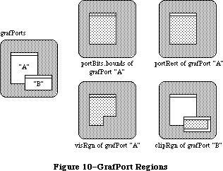 Figure 10–GrafPort Regions
The bkPat and fillPat fields of a grafPort contain patterns used by certain QuickDraw routines. BkPat is the “background” pattern that’s used when an area is erased or when bits are scrolled out of it. When asked to fill an area with a specified pattern, QuickDraw stores the given pattern in the fillPat field and then calls a low-level drawing routine that gets the pattern from that field. The various graphic operations are discussed in detail later in the descriptions of individual QuickDraw routines.
Of the next ten fields, the first five determine characteristics of the graphics pen and the last five determine characteristics of any text that may be drawn; these are described in separate sections below.
The fgColor, bkColor, and colrBit fields contain values related to drawing in color. FgColor is the grafPort’s foreground color and bkColor is its background color. ColrBit tells the color imaging software which plane of the color picture to draw into. For more information, see “Drawing in Color” in the section “General Discussion of Drawing”.
The patStretch field is used during output to a printer to expand patterns if necessary. The application should not change its value.
The picSave, rgnSave, and polySave fields reflect the state of picture, region, and polygon definition, respectively. The application shouldn’t be concerned about exactly what information the handle, if any, leads to; you may, however, save the current value of rgnSave, set the field to NIL to disable the region definition, and later restore it to the saved value to resume the region definition. The picSave and polySave fields work similarly for pictures and polygons.
Finally, the grafProcs field may point to a special data structure that the application stores into if it wants to customize QuickDraw drawing routines or use QuickDraw in other advanced, highly specialized ways (see “Customizing QuickDraw Operations”). If grafProcs is NIL, QuickDraw responds in the standard ways described in this chapter.
_______________________________________________________________________________
»Pen Characteristics
The pnLoc, pnSize, pnMode, pnPat, and pnVis fields of a grafPort deal with the graphics “pen”. Each grafPort has one and only one such pen, which is used for drawing lines, shapes, and text. The pen has four characteristics: a location, a size (height and width), a drawing mode, and a drawing pattern (see Figure
11).
Figure 10–GrafPort Regions
The bkPat and fillPat fields of a grafPort contain patterns used by certain QuickDraw routines. BkPat is the “background” pattern that’s used when an area is erased or when bits are scrolled out of it. When asked to fill an area with a specified pattern, QuickDraw stores the given pattern in the fillPat field and then calls a low-level drawing routine that gets the pattern from that field. The various graphic operations are discussed in detail later in the descriptions of individual QuickDraw routines.
Of the next ten fields, the first five determine characteristics of the graphics pen and the last five determine characteristics of any text that may be drawn; these are described in separate sections below.
The fgColor, bkColor, and colrBit fields contain values related to drawing in color. FgColor is the grafPort’s foreground color and bkColor is its background color. ColrBit tells the color imaging software which plane of the color picture to draw into. For more information, see “Drawing in Color” in the section “General Discussion of Drawing”.
The patStretch field is used during output to a printer to expand patterns if necessary. The application should not change its value.
The picSave, rgnSave, and polySave fields reflect the state of picture, region, and polygon definition, respectively. The application shouldn’t be concerned about exactly what information the handle, if any, leads to; you may, however, save the current value of rgnSave, set the field to NIL to disable the region definition, and later restore it to the saved value to resume the region definition. The picSave and polySave fields work similarly for pictures and polygons.
Finally, the grafProcs field may point to a special data structure that the application stores into if it wants to customize QuickDraw drawing routines or use QuickDraw in other advanced, highly specialized ways (see “Customizing QuickDraw Operations”). If grafProcs is NIL, QuickDraw responds in the standard ways described in this chapter.
_______________________________________________________________________________
»Pen Characteristics
The pnLoc, pnSize, pnMode, pnPat, and pnVis fields of a grafPort deal with the graphics “pen”. Each grafPort has one and only one such pen, which is used for drawing lines, shapes, and text. The pen has four characteristics: a location, a size (height and width), a drawing mode, and a drawing pattern (see Figure
11).
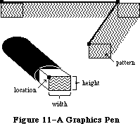 Figure 11–A Graphics Pen
The pnLoc field specifies the point where QuickDraw will begin drawing the next line, shape, or character. It can be anywhere on the coordinate plane: There are no restrictions on the movement or placement of the pen. Remember that the pen location is a point in the grafPort’s coordinate system, not a pixel in a bit image. The top left corner of the pen is at the pen location; the pen hangs below and to the right of this point.
The pen is rectangular in shape, and its width and height are specified by pnSize. The default size is a 1-by-1-bit square; the width and height can range from (0,0) to (30000,30000). If either the pen width or the pen height is less than 1, the pen will not draw.
The pnMode and pnPat fields of a grafPort determine how the bits under the pen are affected when lines or shapes are drawn. The pnPat is a pattern that’s used like the “ink” in the pen. This pattern, like all other patterns drawn in the grafPort, is always aligned with the port’s coordinate system: The top left corner of the pattern is aligned with the top left corner of the portRect, so that adjacent areas of the same pattern will blend into a continuous, coordinated pattern.
The pnMode field determines how the pen pattern is to affect what’s already in the bit image when lines or shapes are drawn. When the pen draws, QuickDraw first determines what bits in the bit image will be affected and finds their corresponding bits in the pattern. It then does a bit-by-bit comparison based on the pen mode, which specifies one of eight Boolean operations to perform. The resulting bit is stored into its proper place in the bit image. The pen modes are described under “Transfer Modes” in the section “General Discussion of Drawing”.
The pnVis field determines the pen’s visibility, that is, whether it draws on the screen. For more information, see the descriptions of HidePen and ShowPen under “Pen and Line-Drawing Routines” in the “QuickDraw Routines” section.
_______________________________________________________________________________
»Text Characteristics
The txFont, txFace, txMode, txSize, and spExtra fields of a grafPort determine how text will be drawn—the font, style, and size of characters and how they will be placed in the bit image. QuickDraw can draw characters as quickly and easily as it draws lines and shapes, and in many prepared fonts. Font means the complete set of characters of one typeface. The characters may be drawn in any size and character style (that is, with stylistic variations such as bold, italic, and underline). Figure 12 shows two characters drawn by QuickDraw and some terms associated with drawing text.
Figure 11–A Graphics Pen
The pnLoc field specifies the point where QuickDraw will begin drawing the next line, shape, or character. It can be anywhere on the coordinate plane: There are no restrictions on the movement or placement of the pen. Remember that the pen location is a point in the grafPort’s coordinate system, not a pixel in a bit image. The top left corner of the pen is at the pen location; the pen hangs below and to the right of this point.
The pen is rectangular in shape, and its width and height are specified by pnSize. The default size is a 1-by-1-bit square; the width and height can range from (0,0) to (30000,30000). If either the pen width or the pen height is less than 1, the pen will not draw.
The pnMode and pnPat fields of a grafPort determine how the bits under the pen are affected when lines or shapes are drawn. The pnPat is a pattern that’s used like the “ink” in the pen. This pattern, like all other patterns drawn in the grafPort, is always aligned with the port’s coordinate system: The top left corner of the pattern is aligned with the top left corner of the portRect, so that adjacent areas of the same pattern will blend into a continuous, coordinated pattern.
The pnMode field determines how the pen pattern is to affect what’s already in the bit image when lines or shapes are drawn. When the pen draws, QuickDraw first determines what bits in the bit image will be affected and finds their corresponding bits in the pattern. It then does a bit-by-bit comparison based on the pen mode, which specifies one of eight Boolean operations to perform. The resulting bit is stored into its proper place in the bit image. The pen modes are described under “Transfer Modes” in the section “General Discussion of Drawing”.
The pnVis field determines the pen’s visibility, that is, whether it draws on the screen. For more information, see the descriptions of HidePen and ShowPen under “Pen and Line-Drawing Routines” in the “QuickDraw Routines” section.
_______________________________________________________________________________
»Text Characteristics
The txFont, txFace, txMode, txSize, and spExtra fields of a grafPort determine how text will be drawn—the font, style, and size of characters and how they will be placed in the bit image. QuickDraw can draw characters as quickly and easily as it draws lines and shapes, and in many prepared fonts. Font means the complete set of characters of one typeface. The characters may be drawn in any size and character style (that is, with stylistic variations such as bold, italic, and underline). Figure 12 shows two characters drawn by QuickDraw and some terms associated with drawing text.
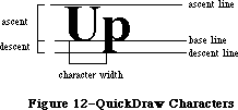 Figure 12–QuickDraw Characters
Text is drawn with the base line positioned at the pen location.
The txFont field is a font number that identifies the character font to be used in the grafPort. The font number 0 represents the system font. For more information about the system font, the other font numbers recognized by the Font Manager, and the construction, layout, and loading of fonts, see the Font Manager chapter.
A character font is defined as a collection of images that make up the individual characters of the font. The characters can be of unequal widths, and they’re not restricted to their “cells”: The lower curl of a lowercase j, for example, can stretch back under the previous character (typographers call this kerning). A font can consist of up to 255 distinct characters, yet not all characters need to be defined in a single font. In addition, each font contains a missing symbol to be drawn in case of a request to draw a character that’s missing from the font.
The txFace field controls the character style of the text with values from the set defined by the Style data type:
TYPE StyleItem = (bold,italic,underline,outline,shadow,condense,extend);
Style = SET OF StyleItem;
Assembly-language note: In assembly language, this set is stored as a word
whose low-order byte contains bits representing the
style. The bit numbers are specified by the following
global constants:
boldBit .EQU 0
italicBit .EQU 1
ulineBit .EQU 2
outlineBit .EQU 3
shadowBit .EQU 5
extendBit .EQU 6
If all bits are 0, it represents the plain character
style.
You can apply stylistic variations either alone or in combination; Figure 13 illustrates some as applied to the Geneva font. Most combinations usually look good only for large font sizes.
Figure 12–QuickDraw Characters
Text is drawn with the base line positioned at the pen location.
The txFont field is a font number that identifies the character font to be used in the grafPort. The font number 0 represents the system font. For more information about the system font, the other font numbers recognized by the Font Manager, and the construction, layout, and loading of fonts, see the Font Manager chapter.
A character font is defined as a collection of images that make up the individual characters of the font. The characters can be of unequal widths, and they’re not restricted to their “cells”: The lower curl of a lowercase j, for example, can stretch back under the previous character (typographers call this kerning). A font can consist of up to 255 distinct characters, yet not all characters need to be defined in a single font. In addition, each font contains a missing symbol to be drawn in case of a request to draw a character that’s missing from the font.
The txFace field controls the character style of the text with values from the set defined by the Style data type:
TYPE StyleItem = (bold,italic,underline,outline,shadow,condense,extend);
Style = SET OF StyleItem;
Assembly-language note: In assembly language, this set is stored as a word
whose low-order byte contains bits representing the
style. The bit numbers are specified by the following
global constants:
boldBit .EQU 0
italicBit .EQU 1
ulineBit .EQU 2
outlineBit .EQU 3
shadowBit .EQU 5
extendBit .EQU 6
If all bits are 0, it represents the plain character
style.
You can apply stylistic variations either alone or in combination; Figure 13 illustrates some as applied to the Geneva font. Most combinations usually look good only for large font sizes.
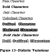 Figure 13–Stylistic Variations
If you specify bold, each character is repeatedly drawn one bit to the right an appropriate number of times for extra thickness.
Italic adds an italic slant to the characters. Character bits above the base line are skewed right; bits below the base line are skewed left.
Underline draws a line below the base line of the characters. If part of a character descends below the base line (as “y” in Figure 13), the underline
isn’t drawn through the pixel on either side of the descending part.
Outline makes a hollow, outlined character rather than a solid one. Shadow also makes an outlined character, but the outline is thickened below and to the right of the character to achieve the effect of a shadow. If you specify bold along with outline or shadow, the hollow part of the character is widened.
Condense and extend affect the horizontal distance between all characters, including spaces. Condense decreases the distance between characters and extend increases it, by an amount that the Font Manager determines is appropriate.
The txMode field controls the way characters are placed in the bit image. It functions much like a pnMode: When a character is drawn, QuickDraw determines which bits in the bit image will be affected, does a bit-by-bit comparison based on the mode, and stores the resulting bits into the bit image. These modes are described under “Transfer Modes” in the section “General Discussion of Drawing”. Only three of them—srcOr, srcXor, and srcBic—should be used for drawing text.
Note: If you use scrCopy, some extra blank space will be appended at the
end of the text.
The txSize field specifies the font size in points (where “point” is a typographical term meaning approximately 1/72 inch). Any size from 1 to 127 points may be specified. If the Font Manager doesn’t have the font in a specified size, it will scale a size it does have as necessary to produce the size desired. A value of 0 in this field represents the system font size (12 points).
Finally, the spExtra field is useful when a line of characters is to be drawn justified such that it’s aligned with both a left and a right margin (sometimes called “full justification”). SpExtra contains a fixed-point number equal to the average number of pixels by which each space character should be widened to fill out the line. The Fixed data type is described in the Macintosh Memory Management: An Introduction chapter.
_______________________________________________________________________________
»COORDINATES IN GRAFPORTS
_______________________________________________________________________________
Each grafPort has its own local coordinate system. All fields in the grafPort are expressed in these coordinates, and all calculations and actions performed in QuickDraw use the local coordinate system of the currently selected port.
Two things are important to remember:
• Each grafPort maps a portion of the coordinate plane into a similarly-
sized portion of a bit image.
• The portBits.bounds rectangle defines the local coordinates for a grafPort.
The top left corner of portBits.bounds is always aligned around the first bit in the bit image; the coordinates of that corner “anchor” a point on the grid to that bit in the bit image. This forms a common reference point for multiple grafPorts that use the same bit image (such as the screen); given a portBits.bounds rectangle for each port, you know that their top left corners coincide.
The relationship between the portBits.bounds and portRect rectangles is very important: The portBits.bounds rectangle establishes a coordinate system for the port, and the portRect rectangle indicates the section of the coordinate plane (and thus the bit image) that will be used for drawing. The portRect usually falls inside the portBits.bounds rectangle, but it’s not required to do so.
When a new grafPort is created, its bit map is set to point to the entire screen, and both the portBits.bounds and the portRect are set to rectangles enclosing the screen. The point (0,0) corresponds to the screen’s top left corner.
You can redefine the local coordinates of the top left corner of the grafPort’s portRect, using the SetOrigin procedure. This offsets the coordinates of the grafPort’s portBits.bounds rectangle, recalculating the coordinates of all points in the grafPort to be relative to the new corner coordinates. For example, consider these procedure calls:
SetPort(gamePort);
SetOrigin(90,80)
The call to SetPort sets the current grafPort to gamePort; the call to SetOrigin changes the local coordinates of the top left corner of that port’s portRect to (90,80) (see Figure 14).
Figure 13–Stylistic Variations
If you specify bold, each character is repeatedly drawn one bit to the right an appropriate number of times for extra thickness.
Italic adds an italic slant to the characters. Character bits above the base line are skewed right; bits below the base line are skewed left.
Underline draws a line below the base line of the characters. If part of a character descends below the base line (as “y” in Figure 13), the underline
isn’t drawn through the pixel on either side of the descending part.
Outline makes a hollow, outlined character rather than a solid one. Shadow also makes an outlined character, but the outline is thickened below and to the right of the character to achieve the effect of a shadow. If you specify bold along with outline or shadow, the hollow part of the character is widened.
Condense and extend affect the horizontal distance between all characters, including spaces. Condense decreases the distance between characters and extend increases it, by an amount that the Font Manager determines is appropriate.
The txMode field controls the way characters are placed in the bit image. It functions much like a pnMode: When a character is drawn, QuickDraw determines which bits in the bit image will be affected, does a bit-by-bit comparison based on the mode, and stores the resulting bits into the bit image. These modes are described under “Transfer Modes” in the section “General Discussion of Drawing”. Only three of them—srcOr, srcXor, and srcBic—should be used for drawing text.
Note: If you use scrCopy, some extra blank space will be appended at the
end of the text.
The txSize field specifies the font size in points (where “point” is a typographical term meaning approximately 1/72 inch). Any size from 1 to 127 points may be specified. If the Font Manager doesn’t have the font in a specified size, it will scale a size it does have as necessary to produce the size desired. A value of 0 in this field represents the system font size (12 points).
Finally, the spExtra field is useful when a line of characters is to be drawn justified such that it’s aligned with both a left and a right margin (sometimes called “full justification”). SpExtra contains a fixed-point number equal to the average number of pixels by which each space character should be widened to fill out the line. The Fixed data type is described in the Macintosh Memory Management: An Introduction chapter.
_______________________________________________________________________________
»COORDINATES IN GRAFPORTS
_______________________________________________________________________________
Each grafPort has its own local coordinate system. All fields in the grafPort are expressed in these coordinates, and all calculations and actions performed in QuickDraw use the local coordinate system of the currently selected port.
Two things are important to remember:
• Each grafPort maps a portion of the coordinate plane into a similarly-
sized portion of a bit image.
• The portBits.bounds rectangle defines the local coordinates for a grafPort.
The top left corner of portBits.bounds is always aligned around the first bit in the bit image; the coordinates of that corner “anchor” a point on the grid to that bit in the bit image. This forms a common reference point for multiple grafPorts that use the same bit image (such as the screen); given a portBits.bounds rectangle for each port, you know that their top left corners coincide.
The relationship between the portBits.bounds and portRect rectangles is very important: The portBits.bounds rectangle establishes a coordinate system for the port, and the portRect rectangle indicates the section of the coordinate plane (and thus the bit image) that will be used for drawing. The portRect usually falls inside the portBits.bounds rectangle, but it’s not required to do so.
When a new grafPort is created, its bit map is set to point to the entire screen, and both the portBits.bounds and the portRect are set to rectangles enclosing the screen. The point (0,0) corresponds to the screen’s top left corner.
You can redefine the local coordinates of the top left corner of the grafPort’s portRect, using the SetOrigin procedure. This offsets the coordinates of the grafPort’s portBits.bounds rectangle, recalculating the coordinates of all points in the grafPort to be relative to the new corner coordinates. For example, consider these procedure calls:
SetPort(gamePort);
SetOrigin(90,80)
The call to SetPort sets the current grafPort to gamePort; the call to SetOrigin changes the local coordinates of the top left corner of that port’s portRect to (90,80) (see Figure 14).
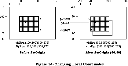 Figure 14–Changing Local Coordinates
This offsets the coordinates of the following elements:
gamePort^.portBits.bounds
gamePort^.portRect
gamePort^.visRgn
These three elements are always kept “in sync”.
Notice that when the local coordinates of a grafPort are offset, the grafPort’s clipRgn and pen location are not offset. A good way to think of it is that the port’s structure “sticks” to the screen, while the document in the grafPort
(along with the pen and clipRgn) “sticks” to the coordinate system. For example, in Figure 14, before SetOrigin, the visRgn and clipRgn are the same as the portRect. After the SetOrigin call, the locations of portBits.bounds, portRect, and visRgn do not change on the screen; their coordinates are simply offset. As always, the top left corner of portBits.bounds remains “anchored” around the first bit in the bit image (the first pixel on the screen); the image on the screen doesn’t move as a result of SetOrigin. However, the pen location and clipRgn do move on the screen; the top left corner of the clipRgn is still
(100,100), but this location has moved down and to the right, and the pen has similarly moved.
If you’re moving, comparing, or otherwise dealing with mathematical items in different grafPorts (for example, finding the intersection of two regions in two different grafPorts), you must adjust to a common coordinate system before you perform the operation. A QuickDraw procedure, LocalToGlobal, lets you convert a point’s local coordinates to a global coordinate system where the top left corner of the bit image is (0,0); by converting the various local coordinates to global coordinates, you can compare and mix them with confidence. For more information, see the description of LocaltoGlobal under “Calculations with Points” in the “QuickDraw Routines” section.
_______________________________________________________________________________
»GENERAL DISCUSSION OF DRAWING
_______________________________________________________________________________
Drawing occurs:
• always inside a grafPort, in the bit image and coordinate system
defined by the grafPort’s bit map
• always within the intersection of the grafPort’s portBits.bounds
and portRect, and clipped to its visRgn and clipRgn
• always at the grafPort’s pen location
• usually with the grafPort’s pen size, pattern, and mode
With QuickDraw routines, you can draw lines, shapes, and text. Shapes include rectangles, ovals, rounded-corner rectangles, wedge-shaped sections of ovals, regions, and polygons.
Lines are defined by two points: the current pen location and a destination location. When drawing a line, QuickDraw moves the top left corner of the pen along the mathematical trajectory from the current location to the destination. The pen hangs below and to the right of the trajectory (see Figure 15).
Figure 14–Changing Local Coordinates
This offsets the coordinates of the following elements:
gamePort^.portBits.bounds
gamePort^.portRect
gamePort^.visRgn
These three elements are always kept “in sync”.
Notice that when the local coordinates of a grafPort are offset, the grafPort’s clipRgn and pen location are not offset. A good way to think of it is that the port’s structure “sticks” to the screen, while the document in the grafPort
(along with the pen and clipRgn) “sticks” to the coordinate system. For example, in Figure 14, before SetOrigin, the visRgn and clipRgn are the same as the portRect. After the SetOrigin call, the locations of portBits.bounds, portRect, and visRgn do not change on the screen; their coordinates are simply offset. As always, the top left corner of portBits.bounds remains “anchored” around the first bit in the bit image (the first pixel on the screen); the image on the screen doesn’t move as a result of SetOrigin. However, the pen location and clipRgn do move on the screen; the top left corner of the clipRgn is still
(100,100), but this location has moved down and to the right, and the pen has similarly moved.
If you’re moving, comparing, or otherwise dealing with mathematical items in different grafPorts (for example, finding the intersection of two regions in two different grafPorts), you must adjust to a common coordinate system before you perform the operation. A QuickDraw procedure, LocalToGlobal, lets you convert a point’s local coordinates to a global coordinate system where the top left corner of the bit image is (0,0); by converting the various local coordinates to global coordinates, you can compare and mix them with confidence. For more information, see the description of LocaltoGlobal under “Calculations with Points” in the “QuickDraw Routines” section.
_______________________________________________________________________________
»GENERAL DISCUSSION OF DRAWING
_______________________________________________________________________________
Drawing occurs:
• always inside a grafPort, in the bit image and coordinate system
defined by the grafPort’s bit map
• always within the intersection of the grafPort’s portBits.bounds
and portRect, and clipped to its visRgn and clipRgn
• always at the grafPort’s pen location
• usually with the grafPort’s pen size, pattern, and mode
With QuickDraw routines, you can draw lines, shapes, and text. Shapes include rectangles, ovals, rounded-corner rectangles, wedge-shaped sections of ovals, regions, and polygons.
Lines are defined by two points: the current pen location and a destination location. When drawing a line, QuickDraw moves the top left corner of the pen along the mathematical trajectory from the current location to the destination. The pen hangs below and to the right of the trajectory (see Figure 15).
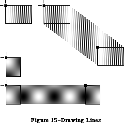 Figure 15–Drawing Lines
Note: No mathematical element (such as the pen location) is ever affected
by clipping; clipping only determines what appears where in the bit
image. If you draw a line to a location outside the intersection of
the portRect, visRgn and clipRgn, the pen location will move there,
but only the portion of the line that’s inside that area will actually
be drawn. This is true for all drawing routines.
Rectangles, ovals, and rounded-corner rectangles are defined by two corner points. The shapes always appear inside the mathematical rectangle defined by the two points. A region is defined in a more complex manner, but also appears only within the rectangle enclosing it. Remember, these enclosing rectangles have infinitely thin borders and are not visible on the screen.
As illustrated in Figure 16, shapes may be drawn either solid (filled in with a pattern) or framed (outlined and hollow).
Figure 15–Drawing Lines
Note: No mathematical element (such as the pen location) is ever affected
by clipping; clipping only determines what appears where in the bit
image. If you draw a line to a location outside the intersection of
the portRect, visRgn and clipRgn, the pen location will move there,
but only the portion of the line that’s inside that area will actually
be drawn. This is true for all drawing routines.
Rectangles, ovals, and rounded-corner rectangles are defined by two corner points. The shapes always appear inside the mathematical rectangle defined by the two points. A region is defined in a more complex manner, but also appears only within the rectangle enclosing it. Remember, these enclosing rectangles have infinitely thin borders and are not visible on the screen.
As illustrated in Figure 16, shapes may be drawn either solid (filled in with a pattern) or framed (outlined and hollow).
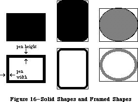 Figure 16–Solid Shapes and Framed Shapes
In the case of framed shapes, the outline appears completely within the enclosing rectangle—with one exception—and the vertical and horizontal thickness of the outline is determined by the pen size. The exception is polygons, as discussed in the section “Pictures and Polygons” below.
The pen pattern is used to fill in the bits that are affected by the drawing operation. The pen mode defines how those bits are to be affected by directing QuickDraw to apply one of eight Boolean operations to the bits in the shape and the corresponding pixels on the screen.
Text drawing doesn’t use the pnSize, pnPat, or pnMode, but it does use the pnLoc. QuickDraw starts drawing each character from the current pen location, with the character’s base line at the pen location. After a character is drawn, the pen moves to the right to the location where it will draw the next character. No wraparound or carriage return is performed automatically. Clipping of text is performed in exactly the same manner as all other clipping in QuickDraw.
_______________________________________________________________________________
»Transfer Modes
When lines or shapes are drawn, the pnMode field of the grafPort determines how the drawing is to appear in the port’s bit image; similarly, the txMode field determines how text is to appear. There’s also a QuickDraw procedure that transfers a bit image from one bit map to another, and this procedure has a mode parameter that determines the appearance of the result. In all these cases, the mode, called a transfer mode, specifies one of eight Boolean operations: For each bit in the item to be drawn, QuickDraw finds the corresponding bit in the destination bit map, performs the Boolean operation on the pair of bits, and stores the resulting bit into the bit image.
There are two types of transfer mode:
• pattern transfer modes, for drawing lines or shapes with a pattern
• source transfer modes, for drawing text or transferring any bit
image between two bit maps
For each type of mode, there are four basic operations—Copy, Or, Xor, and Bic
(“bit clear”). The Copy operation simply replaces the pixels in the destination with the pixels in the pattern or source, “painting” over the destination without regard for what’s already there. The Or, Xor, and Bic operations leave the destination pixels under the white part of the pattern or source unchanged, and differ in how they affect the pixels under the black part: Or replaces those pixels with black pixels, thus “overlaying” the destination with the black part of the pattern or source; Xor inverts the pixels under the black part; and Bic erases them to white.
Each of the basic operations has a variant in which every pixel in the pattern or source is inverted before the operation is performed, giving eight operations in all. Each mode is defined by name as a constant in QuickDraw (see Figure 17).
Figure 16–Solid Shapes and Framed Shapes
In the case of framed shapes, the outline appears completely within the enclosing rectangle—with one exception—and the vertical and horizontal thickness of the outline is determined by the pen size. The exception is polygons, as discussed in the section “Pictures and Polygons” below.
The pen pattern is used to fill in the bits that are affected by the drawing operation. The pen mode defines how those bits are to be affected by directing QuickDraw to apply one of eight Boolean operations to the bits in the shape and the corresponding pixels on the screen.
Text drawing doesn’t use the pnSize, pnPat, or pnMode, but it does use the pnLoc. QuickDraw starts drawing each character from the current pen location, with the character’s base line at the pen location. After a character is drawn, the pen moves to the right to the location where it will draw the next character. No wraparound or carriage return is performed automatically. Clipping of text is performed in exactly the same manner as all other clipping in QuickDraw.
_______________________________________________________________________________
»Transfer Modes
When lines or shapes are drawn, the pnMode field of the grafPort determines how the drawing is to appear in the port’s bit image; similarly, the txMode field determines how text is to appear. There’s also a QuickDraw procedure that transfers a bit image from one bit map to another, and this procedure has a mode parameter that determines the appearance of the result. In all these cases, the mode, called a transfer mode, specifies one of eight Boolean operations: For each bit in the item to be drawn, QuickDraw finds the corresponding bit in the destination bit map, performs the Boolean operation on the pair of bits, and stores the resulting bit into the bit image.
There are two types of transfer mode:
• pattern transfer modes, for drawing lines or shapes with a pattern
• source transfer modes, for drawing text or transferring any bit
image between two bit maps
For each type of mode, there are four basic operations—Copy, Or, Xor, and Bic
(“bit clear”). The Copy operation simply replaces the pixels in the destination with the pixels in the pattern or source, “painting” over the destination without regard for what’s already there. The Or, Xor, and Bic operations leave the destination pixels under the white part of the pattern or source unchanged, and differ in how they affect the pixels under the black part: Or replaces those pixels with black pixels, thus “overlaying” the destination with the black part of the pattern or source; Xor inverts the pixels under the black part; and Bic erases them to white.
Each of the basic operations has a variant in which every pixel in the pattern or source is inverted before the operation is performed, giving eight operations in all. Each mode is defined by name as a constant in QuickDraw (see Figure 17).
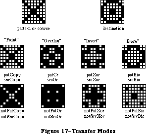 Figure 17–Transfer Modes
Pattern Source Action on each pixel in destination:
transfer transfer If black pixel in If white pixel in
mode mode pattern or source pattern or source
patCopy srcCopy Force black Force white
patOr srcOr Force black Leave alone
patXor srcXor Invert Leave alone
patBic srcBic Force white Leave alone
notPatCopy notSrcCopy Force white Force black
notPatOr notSrcOr Leave alone Force black
notPatXor notSrcXor Leave alone Invert
notPatBic notSrcBic Leave alone Force white
_______________________________________________________________________________
»Drawing in Color
Your application can draw on color output devices by using QuickDraw procedures to set the foreground color and the background color. Eight standard colors may be specified with the following predefined constants:
CONST blackColor = 33;
whiteColor = 30;
redColor = 209;
greenColor = 329;
blueColor = 389;
cyanColor = 269;
magentaColor = 149;
yellowColor = 89;
Initially, the foreground color is blackColor and the background color is whiteColor. If you specify a color other than whiteColor, it will appear as black on a black-and-white output device.
To apply the table in the “Transfer Modes” section above to drawing in color, make the following translation: Where the table shows “Force black”, read
“Force foreground color”, and where it shows “Force white”, read “Force background color”. The effect of inverting a color depends on the device being used.
Note: QuickDraw can support output devices that have up to 32 bits of color
information per pixel. A color picture may be thought of, then, as
having up to 32 planes. At any one time, QuickDraw draws into only
one of these planes. A QuickDraw routine called by the color-imaging
software specifies which plane.
X-Ref: Technical Note #73
_______________________________________________________________________________
»PICTURES AND POLYGONS
_______________________________________________________________________________
QuickDraw lets you save a sequence of drawing commands and “play them back” later with a single procedure call. There are two such mechanisms: one for drawing any picture to scale in a destination rectangle that you specify, and another for drawing polygons in all the ways you can draw other shapes in QuickDraw.
_______________________________________________________________________________
»»Pictures
A picture in QuickDraw is a transcript of calls to routines that draw something—anything—in a bit image. Pictures make it easy for one program to draw something defined in another program, with great flexibility and without knowing the details about what’s being drawn.
For each picture you define, you specify a rectangle that surrounds it; this rectangle is called the picture frame. When you later call the procedure that plays back the saved picture, you supply a destination rectangle, and QuickDraw scales the picture so that its frame is completely aligned with the destination rectangle. Thus, the picture may be expanded or shrunk to fit its destination rectangle. For example, if the picture is a circle inside a square picture frame, and the destination rectangle is not square, the picture will be drawn as an oval.
Since a picture may include any sequence of drawing commands, its data structure is a variable-length entity. It consists of two fixed-length fields followed by a variable-length field:
TYPE Picture = RECORD
picSize: INTEGER; {size in bytes}
picFrame: Rect; {picture frame}
{picture definition data}
END;
The picSize field contains the size, in bytes, of the picture variable. The picFrame field is the picture frame that surrounds the picture and gives a frame of reference for scaling when the picture is played back. The rest of the structure contains a compact representation of the drawing commands that define the picture.
All pictures are accessed through handles:
TYPE PicPtr = ^Picture;
PicHandle = ^PicPtr;
To define a picture, you call a QuickDraw function that returns a picHandle, and then call the drawing routines that define the picture.
QuickDraw also allows you to intersperse picture comments with the definition of a picture. These comments, which do not affect the picture’s appearance, may be used to provide additional information about the picture when it’s played back. This is especially valuable when pictures are transmitted from one application to another. There are two standard types of comments which, like parentheses, serve to group drawing commands together (such as all the commands that draw a particular part of a picture):
CONST picLParen = 0;
picRParen = 1;
The application defining the picture can use these standard comments as well as comments of its own design.
X-Ref: Technical Note #21
X-Ref: Technical Note #91
X-Ref: Technical Note #154
_______________________________________________________________________________
»Polygons
Polygons are similar to pictures in that you define them by a sequence of calls to QuickDraw routines. They’re also similar to other shapes that QuickDraw knows about, since there’s a set of procedures for performing graphic operations and calculations on them.
A polygon is simply any sequence of connected lines (see Figure 18). You define a polygon by moving to the starting point of the polygon and drawing lines from there to the next point, from that point to the next, and so on.
The data structure for a polygon consists of two fixed-length fields followed by a variable-length array:
TYPE Polygon = RECORD
polySize: INTEGER; {size in bytes}
polyBBox: Rect; {enclosing rectangle}
polyPoints: ARRAY[0..0] OF Point
END;
Figure 17–Transfer Modes
Pattern Source Action on each pixel in destination:
transfer transfer If black pixel in If white pixel in
mode mode pattern or source pattern or source
patCopy srcCopy Force black Force white
patOr srcOr Force black Leave alone
patXor srcXor Invert Leave alone
patBic srcBic Force white Leave alone
notPatCopy notSrcCopy Force white Force black
notPatOr notSrcOr Leave alone Force black
notPatXor notSrcXor Leave alone Invert
notPatBic notSrcBic Leave alone Force white
_______________________________________________________________________________
»Drawing in Color
Your application can draw on color output devices by using QuickDraw procedures to set the foreground color and the background color. Eight standard colors may be specified with the following predefined constants:
CONST blackColor = 33;
whiteColor = 30;
redColor = 209;
greenColor = 329;
blueColor = 389;
cyanColor = 269;
magentaColor = 149;
yellowColor = 89;
Initially, the foreground color is blackColor and the background color is whiteColor. If you specify a color other than whiteColor, it will appear as black on a black-and-white output device.
To apply the table in the “Transfer Modes” section above to drawing in color, make the following translation: Where the table shows “Force black”, read
“Force foreground color”, and where it shows “Force white”, read “Force background color”. The effect of inverting a color depends on the device being used.
Note: QuickDraw can support output devices that have up to 32 bits of color
information per pixel. A color picture may be thought of, then, as
having up to 32 planes. At any one time, QuickDraw draws into only
one of these planes. A QuickDraw routine called by the color-imaging
software specifies which plane.
X-Ref: Technical Note #73
_______________________________________________________________________________
»PICTURES AND POLYGONS
_______________________________________________________________________________
QuickDraw lets you save a sequence of drawing commands and “play them back” later with a single procedure call. There are two such mechanisms: one for drawing any picture to scale in a destination rectangle that you specify, and another for drawing polygons in all the ways you can draw other shapes in QuickDraw.
_______________________________________________________________________________
»»Pictures
A picture in QuickDraw is a transcript of calls to routines that draw something—anything—in a bit image. Pictures make it easy for one program to draw something defined in another program, with great flexibility and without knowing the details about what’s being drawn.
For each picture you define, you specify a rectangle that surrounds it; this rectangle is called the picture frame. When you later call the procedure that plays back the saved picture, you supply a destination rectangle, and QuickDraw scales the picture so that its frame is completely aligned with the destination rectangle. Thus, the picture may be expanded or shrunk to fit its destination rectangle. For example, if the picture is a circle inside a square picture frame, and the destination rectangle is not square, the picture will be drawn as an oval.
Since a picture may include any sequence of drawing commands, its data structure is a variable-length entity. It consists of two fixed-length fields followed by a variable-length field:
TYPE Picture = RECORD
picSize: INTEGER; {size in bytes}
picFrame: Rect; {picture frame}
{picture definition data}
END;
The picSize field contains the size, in bytes, of the picture variable. The picFrame field is the picture frame that surrounds the picture and gives a frame of reference for scaling when the picture is played back. The rest of the structure contains a compact representation of the drawing commands that define the picture.
All pictures are accessed through handles:
TYPE PicPtr = ^Picture;
PicHandle = ^PicPtr;
To define a picture, you call a QuickDraw function that returns a picHandle, and then call the drawing routines that define the picture.
QuickDraw also allows you to intersperse picture comments with the definition of a picture. These comments, which do not affect the picture’s appearance, may be used to provide additional information about the picture when it’s played back. This is especially valuable when pictures are transmitted from one application to another. There are two standard types of comments which, like parentheses, serve to group drawing commands together (such as all the commands that draw a particular part of a picture):
CONST picLParen = 0;
picRParen = 1;
The application defining the picture can use these standard comments as well as comments of its own design.
X-Ref: Technical Note #21
X-Ref: Technical Note #91
X-Ref: Technical Note #154
_______________________________________________________________________________
»Polygons
Polygons are similar to pictures in that you define them by a sequence of calls to QuickDraw routines. They’re also similar to other shapes that QuickDraw knows about, since there’s a set of procedures for performing graphic operations and calculations on them.
A polygon is simply any sequence of connected lines (see Figure 18). You define a polygon by moving to the starting point of the polygon and drawing lines from there to the next point, from that point to the next, and so on.
The data structure for a polygon consists of two fixed-length fields followed by a variable-length array:
TYPE Polygon = RECORD
polySize: INTEGER; {size in bytes}
polyBBox: Rect; {enclosing rectangle}
polyPoints: ARRAY[0..0] OF Point
END;
 Figure 18–Polygons
The polySize field contains the size, in bytes, of the polygon variable. The maximum size of a polygon is 32K bytes. The polyBBox field is a rectangle that just encloses the entire polygon. The polyPoints array expands as necessary to contain the points of the polygon—the starting point followed by each successive point to which a line is drawn.
Like pictures and regions, polygons are accessed through handles:
TYPE PolyPtr = ^Polygon;
PolyHandle = ^PolyPtr;
To define a polygon, you call a routine that returns a polyHandle, and then call the line-drawing routines that define the polygon.
Just as for other shapes that QuickDraw knows about, there’s a set of graphic operations to draw polygons on the screen. QuickDraw draws a polygon by moving to the starting point and then drawing lines to the remaining points in succession, just as when the routines were called to define the polygon. In this sense it “plays back” those routine calls. As a result, polygons are not treated exactly the same as other QuickDraw shapes. For example, the procedure that frames a polygon draws outside the actual boundary of the polygon, because QuickDraw line-drawing routines draw below and to the right of the pen location. The procedures that fill a polygon with a pattern, however, stay within the boundary of the polygon; if the polygon’s ending point isn’t the same as its starting point, these procedures add a line between them to complete the shape.
QuickDraw also scales a polygon differently from a similarly-shaped region if it’s being drawn as part of a picture: When stretched, a slanted line is drawn more smoothly if it’s part of a polygon rather than a region. You may find it helpful to keep in mind the conceptual difference between polygons and regions: A polygon is treated more as a continuous shape, a region more as a set of bits.
_______________________________________________________________________________
»USING QUICKDRAW
_______________________________________________________________________________
Call the InitGraf procedure to initialize QuickDraw at the beginning of your program, before initializing any other parts of the Toolbox.
When your application starts up, the cursor will be a wristwatch; the Finder sets it to this to indicate that a lengthy operation is in progress. Call the InitCursor procedure when the application is ready to respond to user input, to change the cursor to the standard arrow. Each time through the main event loop, you should call SetCursor to change the cursor as appropriate for its screen location.
All graphic operations are performed in grafPorts. Before a grafPort can be used, it must be allocated and initialized with the OpenPort procedure. Normally, you don’t call OpenPort yourself—in most cases your application will draw into a window you’ve created with Window Manager routines, and these routines call OpenPort to create the window’s grafPort. Likewise, a grafPort’s regions are disposed of with ClosePort, and the grafPort itself is disposed of with the Memory Manager procedure DisposPtr—but when you call the Window Manager to close or dispose of a window, it calls these routines for you.
In an application that uses multiple windows, each is a separate grafPort. If your application draws into more than one grafPort, you can call SetPort to set the grafPort that you want to draw in. At times you may need to preserve the current grafPort; you can do this by calling GetPort to save the current port, SetPort to set the port you want to draw in, and then SetPort again when you need to restore the previous port.
Each grafPort has its own local coordinate system. Some Toolbox routines return or expect points that are expressed in a common, global coordinate system, while others use local coordinates. For example, when the Event Manager reports an event, it gives the mouse location in global coordinates; but when you call the Control Manager to find out whether the user clicked in a control in one of your windows, you pass the mouse location in local coordinates. The GlobalToLocal procedure lets you convert global coordinates to local coordinates, and the LocalToGlobal procedure lets you do the reverse.
The SetOrigin procedure will adjust a grafPort’s local coordinate system. If your application performs scrolling, you’ll use ScrollRect to shift the bits of the image, and then SetOrigin to readjust the coordinate system after this shift.
You can redefine a grafPort’s clipping region with the SetClip or ClipRect procedure. Just as GetPort and SetPort are used to preserve the current grafPort, GetClip and SetClip are useful for saving the grafPort’s clipRgn while you temporarily perform other clipping functions. This is useful, for example, when you want to reset the clipRgn to redraw the newly displayed portion of a document that’s been scrolled.
When drawing text in a grafPort, you can set the font characteristics with TextFont, TextFace, TextMode, and TextSize. CharWidth, StringWidth, or TextWidth will tell you how much horizontal space the text will require, and GetFontInfo will tell you how much vertical space. You can draw text with DrawChar, DrawString, and DrawText.
The LineTo procedure draws a line from the current pen location to a given point, and the Line procedure draws a line between two given points. You can set the pen location with the MoveTo or Move procedure, and set other pen characteristics with PenSize, PenMode, and PenPat.
In addition to drawing text and lines, you can use QuickDraw to draw a variety of shapes. Most of them are defined simply by a rectangle that encloses the shape. Others require you to call a series of routines to define them:
• To define a region, call the NewRgn function to allocate space for it,
then call OpenRgn, and then specify the outline of the region by calling
routines that draw lines and shapes. End the region definition by calling
CloseRgn. When you’re completely done with the region, call DisposeRgn
to release the memory it occupies.
• To define a polygon, call the OpenPoly function and then form the polygon
by calling procedures that draw lines. Call ClosePoly when you’re finished
defining the polygon, and KillPoly when you’re completely done with it.
You can perform the following graphic operations on rectangles, rounded-corner rectangles, ovals, arcs/wedges, regions, and polygons:
• frame, to outline the shape using the current pen pattern and size
• paint, to fill the shape using the current pen pattern
• erase, to paint the shape using the current background pattern
• invert, to invert the pixels in the shape
• fill, to fill the shape with a specified pattern
QuickDraw pictures let you record and play back complex drawing sequences. To define a picture, call the OpenPicture function and then the drawing routines that form the picture. Call ClosePicture when you’re finished defining the picture. To draw a picture, call DrawPicture. When you’re completely done with a picture, call KillPicture (or the Resource Manager procedure ReleaseResource, if the picture’s a resource).
You’ll use points, rectangles, and regions not only when drawing with QuickDraw, but also when using other parts of the Toolbox and Operating System. At times, you may find it useful to perform calculations on these entities. You can, for example, add and subtract points, and perform a number of calculations on rectangles and regions, such as offsetting them, rescaling them, calculating their union or intersection, and so on.
Note: When performing a calculation on entities in different grafPorts,
you need to adjust to a common coordinate system first, by calling
LocalToGlobal to convert to global coordinates.
To transfer a bit image from one bit map to another, you can use the CopyBits procedure. For example, you can call SetPortBits to change the bit map of the current grafPort to an off-screen buffer, draw into that grafPort, and then call CopyBits to transfer the image from the off-screen buffer onto the screen.
The SeedFill and CalcMask procedures operate on a portion of a bitmap. In both routines, srcPtr and dstPtr point to the beginning of the data to be filled or calculated, not to the beginning of the bitmap; both parameters must point to word boundaries in memory. SrcRow and dstRow specify the row width in bytes (in other words, the rowBytes field of the BitMap record) of the source and destination bitmaps respectively. Height and words determine the number of bits to be filled or calculated; words is the width of the rectangle in words and height is the height of the rectangle in pixels. Figure 19 illustrates the use of these parameters.
Figure 18–Polygons
The polySize field contains the size, in bytes, of the polygon variable. The maximum size of a polygon is 32K bytes. The polyBBox field is a rectangle that just encloses the entire polygon. The polyPoints array expands as necessary to contain the points of the polygon—the starting point followed by each successive point to which a line is drawn.
Like pictures and regions, polygons are accessed through handles:
TYPE PolyPtr = ^Polygon;
PolyHandle = ^PolyPtr;
To define a polygon, you call a routine that returns a polyHandle, and then call the line-drawing routines that define the polygon.
Just as for other shapes that QuickDraw knows about, there’s a set of graphic operations to draw polygons on the screen. QuickDraw draws a polygon by moving to the starting point and then drawing lines to the remaining points in succession, just as when the routines were called to define the polygon. In this sense it “plays back” those routine calls. As a result, polygons are not treated exactly the same as other QuickDraw shapes. For example, the procedure that frames a polygon draws outside the actual boundary of the polygon, because QuickDraw line-drawing routines draw below and to the right of the pen location. The procedures that fill a polygon with a pattern, however, stay within the boundary of the polygon; if the polygon’s ending point isn’t the same as its starting point, these procedures add a line between them to complete the shape.
QuickDraw also scales a polygon differently from a similarly-shaped region if it’s being drawn as part of a picture: When stretched, a slanted line is drawn more smoothly if it’s part of a polygon rather than a region. You may find it helpful to keep in mind the conceptual difference between polygons and regions: A polygon is treated more as a continuous shape, a region more as a set of bits.
_______________________________________________________________________________
»USING QUICKDRAW
_______________________________________________________________________________
Call the InitGraf procedure to initialize QuickDraw at the beginning of your program, before initializing any other parts of the Toolbox.
When your application starts up, the cursor will be a wristwatch; the Finder sets it to this to indicate that a lengthy operation is in progress. Call the InitCursor procedure when the application is ready to respond to user input, to change the cursor to the standard arrow. Each time through the main event loop, you should call SetCursor to change the cursor as appropriate for its screen location.
All graphic operations are performed in grafPorts. Before a grafPort can be used, it must be allocated and initialized with the OpenPort procedure. Normally, you don’t call OpenPort yourself—in most cases your application will draw into a window you’ve created with Window Manager routines, and these routines call OpenPort to create the window’s grafPort. Likewise, a grafPort’s regions are disposed of with ClosePort, and the grafPort itself is disposed of with the Memory Manager procedure DisposPtr—but when you call the Window Manager to close or dispose of a window, it calls these routines for you.
In an application that uses multiple windows, each is a separate grafPort. If your application draws into more than one grafPort, you can call SetPort to set the grafPort that you want to draw in. At times you may need to preserve the current grafPort; you can do this by calling GetPort to save the current port, SetPort to set the port you want to draw in, and then SetPort again when you need to restore the previous port.
Each grafPort has its own local coordinate system. Some Toolbox routines return or expect points that are expressed in a common, global coordinate system, while others use local coordinates. For example, when the Event Manager reports an event, it gives the mouse location in global coordinates; but when you call the Control Manager to find out whether the user clicked in a control in one of your windows, you pass the mouse location in local coordinates. The GlobalToLocal procedure lets you convert global coordinates to local coordinates, and the LocalToGlobal procedure lets you do the reverse.
The SetOrigin procedure will adjust a grafPort’s local coordinate system. If your application performs scrolling, you’ll use ScrollRect to shift the bits of the image, and then SetOrigin to readjust the coordinate system after this shift.
You can redefine a grafPort’s clipping region with the SetClip or ClipRect procedure. Just as GetPort and SetPort are used to preserve the current grafPort, GetClip and SetClip are useful for saving the grafPort’s clipRgn while you temporarily perform other clipping functions. This is useful, for example, when you want to reset the clipRgn to redraw the newly displayed portion of a document that’s been scrolled.
When drawing text in a grafPort, you can set the font characteristics with TextFont, TextFace, TextMode, and TextSize. CharWidth, StringWidth, or TextWidth will tell you how much horizontal space the text will require, and GetFontInfo will tell you how much vertical space. You can draw text with DrawChar, DrawString, and DrawText.
The LineTo procedure draws a line from the current pen location to a given point, and the Line procedure draws a line between two given points. You can set the pen location with the MoveTo or Move procedure, and set other pen characteristics with PenSize, PenMode, and PenPat.
In addition to drawing text and lines, you can use QuickDraw to draw a variety of shapes. Most of them are defined simply by a rectangle that encloses the shape. Others require you to call a series of routines to define them:
• To define a region, call the NewRgn function to allocate space for it,
then call OpenRgn, and then specify the outline of the region by calling
routines that draw lines and shapes. End the region definition by calling
CloseRgn. When you’re completely done with the region, call DisposeRgn
to release the memory it occupies.
• To define a polygon, call the OpenPoly function and then form the polygon
by calling procedures that draw lines. Call ClosePoly when you’re finished
defining the polygon, and KillPoly when you’re completely done with it.
You can perform the following graphic operations on rectangles, rounded-corner rectangles, ovals, arcs/wedges, regions, and polygons:
• frame, to outline the shape using the current pen pattern and size
• paint, to fill the shape using the current pen pattern
• erase, to paint the shape using the current background pattern
• invert, to invert the pixels in the shape
• fill, to fill the shape with a specified pattern
QuickDraw pictures let you record and play back complex drawing sequences. To define a picture, call the OpenPicture function and then the drawing routines that form the picture. Call ClosePicture when you’re finished defining the picture. To draw a picture, call DrawPicture. When you’re completely done with a picture, call KillPicture (or the Resource Manager procedure ReleaseResource, if the picture’s a resource).
You’ll use points, rectangles, and regions not only when drawing with QuickDraw, but also when using other parts of the Toolbox and Operating System. At times, you may find it useful to perform calculations on these entities. You can, for example, add and subtract points, and perform a number of calculations on rectangles and regions, such as offsetting them, rescaling them, calculating their union or intersection, and so on.
Note: When performing a calculation on entities in different grafPorts,
you need to adjust to a common coordinate system first, by calling
LocalToGlobal to convert to global coordinates.
To transfer a bit image from one bit map to another, you can use the CopyBits procedure. For example, you can call SetPortBits to change the bit map of the current grafPort to an off-screen buffer, draw into that grafPort, and then call CopyBits to transfer the image from the off-screen buffer onto the screen.
The SeedFill and CalcMask procedures operate on a portion of a bitmap. In both routines, srcPtr and dstPtr point to the beginning of the data to be filled or calculated, not to the beginning of the bitmap; both parameters must point to word boundaries in memory. SrcRow and dstRow specify the row width in bytes (in other words, the rowBytes field of the BitMap record) of the source and destination bitmaps respectively. Height and words determine the number of bits to be filled or calculated; words is the width of the rectangle in words and height is the height of the rectangle in pixels. Figure 19 illustrates the use of these parameters.
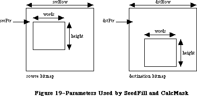 Figure 19–Parameters Used by SeedFill and CalcMask
_______________________________________________________________________________
»QUICKDRAW ROUTINES
_______________________________________________________________________________
»GrafPort Routines
PROCEDURE InitGraf (globalPtr: Ptr);
Call InitGraf once and only once at the beginning of your program to initialize QuickDraw. It initializes the global variables listed below (as well as some private global variables for its own internal use).
Variable Type Initial setting
thePort GrafPtr NIL
white Pattern An all-white pattern
black Pattern An all-black pattern
gray Pattern A 50% gray pattern
ltGray Pattern A 25% gray pattern
dkGray Pattern A 75% gray pattern
arrow Cursor The standard arrow cursor
screenBits BitMap The entire screen
randSeed LONGINT 1
You must pass, in the globalPtr parameter, a pointer to the first QuickDraw global variable, thePort. From Pascal programs, you should always pass @thePort for globalPtr.
Assembly-language note: The QuickDraw global variables are stored in reverse
order, from high to low memory, and require the number
of bytes specified by the global constant grafSize.
Most development systems (including the Lisa Workshop)
preallocate space for these globals immediately below
the location pointed to by register A5. Since thePort
is four bytes, you would pass the globalPtr parameter
as follows:
PEA -4(A5)
_InitGraf
InitGraf stores this pointer to thePort in the
location pointed to by A5. This value is used as a
base address when accessing the other QuickDraw global
variables, which are accessed using negative offsets
(the offsets have the same names as the Pascal global
variables). For example:
MOVE.L (A5),A0 ;point to first
; QuickDraw global
MOVE.L randSeed(A0),A1 ;get global variable
; randSeed
Note: To initialize the cursor, call InitCursor (described under
“Cursor-Handling Routines” below).
PROCEDURE OpenPort (port: GrafPtr);
OpenPort allocates space for the given grafPort’s visRgn and clipRgn, initializes the fields of the grafPort as indicated below, and makes the grafPort the current port (by calling SetPort). OpenPort is called by the Window Manager when you create a window, and you normally won’t call it yourself. If you do call OpenPort, you can create the grafPtr with the Memory Manager procedure NewPtr or reserve the space on the stack (with a variable of type GrafPort).
Field Type Initial setting
device INTEGER 0 (the screen)
portBits BitMap screenBits
portRect Rect screenBits.bounds
visRgn RgnHandle handle to a rectangular region coincident
with screenBits.bounds
clipRgn RgnHandle handle to the rectangular region
(–32767,–32767) (32767,32767)
bkPat Pattern white
fillPat Pattern black
pnLoc Point (0,0)
pnSize Point (1,1)
pnMode INTEGER patCopy
pnPat Pattern black
pnVis INTEGER 0 (visible)
txFont INTEGER 0 (system font)
txFace Style plain
txMode INTEGER srcOr
txSize INTEGER 0 (system font size)
spExtra Fixed 0
fgColor LONGINT blackColor
bkColor LONGINT whiteColor
colrBit INTEGER 0
patStretch INTEGER 0
picSave Handle NIL
rgnSave Handle NIL
polySave Handle NIL
grafProcs QDProcsPtr NIL
PROCEDURE InitPort (port: GrafPtr);
Given a pointer to a grafPort that’s been opened with OpenPort, InitPort reinitializes the fields of the grafPort and makes it the current port. It’s unlikely that you’ll ever have a reason to call this procedure.
Note: InitPort does everything OpenPort does except allocate space for
the visRgn and clipRgn.
PROCEDURE ClosePort (port: GrafPtr);
ClosePort releases the memory occupied by the given grafPort’s visRgn and clipRgn. When you’re completely through with a grafPort, call this procedure and then dispose of the grafPort with the Memory Manager procedure DisposPtr
(if it was allocated with NewPtr). This is normally done for you when you call the Window Manager to close or dispose of a window.
Warning: If ClosePort isn’t called before a grafPort is disposed of, the
memory used by the visRgn and clipRgn will be unrecoverable.
PROCEDURE SetPort (port: GrafPtr);
SetPort makes the specified grafPort the current port.
Note: Only SetPort (and OpenPort and InitPort, which call it) changes the
current port. All the other routines in the Toolbox and Operating
System (even those that call SetPort, OpenPort, or InitPort) leave
the current port set to what it was when they were called.
The global variable thePort always points to the current port. All QuickDraw drawing routines affect the bit map thePort^.portBits and use the local coordinate system of thePort^.
Each port has its own pen and text characteristics, which remain unchanged when the port isn’t selected as the current port.
PROCEDURE GetPort (VAR port: GrafPtr);
GetPort returns a pointer to the current grafPort. This pointer is also available through the global variable thePort, but you may prefer to use GetPort for better readability of your program text. For example, a procedure could do a GetPort(savePort) before setting its own grafPort and a
SetPort(savePort) afterwards to restore the previous port.
PROCEDURE GrafDevice (device: INTEGER);
GrafDevice sets the device field of the current grafPort to the given value, which consists of device-specific information that’s used by the Font Manager to achieve the best possible results when drawing text in the grafPort. The initial value of the device field is 0, for best results on output to the screen. For more information, see the Font Manager chapter.
Note: This field is used for communication between QuickDraw and the Font
Manager; normally you won’t set it yourself.
PROCEDURE SetPortBits (bm: BitMap);
Assembly-language note: The macro you invoke to call SetPortBits from
assembly language is named _SetPBits.
SetPortBits sets the portBits field of the current grafPort to any previously defined bit map. This allows you to perform all normal drawing and calculations on a buffer other than the screen—for example, a small off-screen image for later “stamping” onto the screen (with the CopyBits procedure, described under
“Bit Transfer Operations” below).
Remember to prepare all fields of the bit map before you call SetPortBits.
PROCEDURE PortSize (width,height: INTEGER);
PortSize changes the size of the current grafPort’s portRect. This does not affect the screen; it merely changes the size of the “active area” of the grafPort.
Note: This procedure is normally called only by the Window Manager.
The top left corner of the portRect remains at its same location; the width and height of the portRect are set to the given width and height. In other words, PortSize moves the bottom right corner of the portRect to a position relative to the top left corner.
PortSize doesn’t change the clipRgn or the visRgn, nor does it affect the local coordinate system of the grafPort: It changes only the portRect’s width and height. Remember that all drawing occurs only in the intersection of the portBits.bounds and the portRect, clipped to the visRgn and the clipRgn.
PROCEDURE MovePortTo (leftGlobal,topGlobal: INTEGER);
MovePortTo changes the position of the current grafPort’s portRect. This does not affect the screen; it merely changes the location at which subsequent drawing inside the port will appear.
Note: This procedure is normally called only by the Window Manager
and the System Error Handler.
The leftGlobal and topGlobal parameters set the distance between the top left corner of portBits.bounds and the top left corner of the new portRect.
Like PortSize, MovePortTo doesn’t change the clipRgn or the visRgn, nor does it affect the local coordinate system of the grafPort.
PROCEDURE SetOrigin (h,v: INTEGER);
SetOrigin changes the local coordinate system of the current grafPort. This does not affect the screen; it does, however, affect where subsequent drawing inside the port will appear.
The h and v parameters set the coordinates of the top left corner of the portRect. All other coordinates are calculated from this point; SetOrigin also offsets the coordinates of the portBits.bounds rectangle and the visRgn. Relative distances among elements in the port remain the same; only their absolute local coordinates change. All subsequent drawing and calculation routines use the new coordinate system.
Note: SetOrigin does not offset the coordinates of the clipRgn or the pen;
the pen and clipRgn “stick” to the coordinate system, and therefore
change position on the screen (unlike the portBits.bounds, portRect,
and visRgn, which “stick” to the screen, and don’t change position).
See the “Coordinates in GrafPorts” section for an illustration.
SetOrigin is useful for readjusting the coordinate system after a scrolling operation. (See ScrollRect under “Bit Transfer Operations” below.)
Note: All other routines in the Toolbox and Operating System preserve the
local coordinate system of the current grafPort.
PROCEDURE SetClip (rgn: RgnHandle);
SetClip changes the clipping region of the current grafPort to a region that’s equivalent to the given region. Note that this doesn’t change the region handle, but affects the clipping region itself. Since SetClip makes a copy of the given region, any subsequent changes you make to that region will not affect the clipping region of the port.
You can set the clipping region to any arbitrary region, to aid you in drawing inside the grafPort. The initial clipRgn is an arbitrarily large rectangle.
Note: All routines in the Toolbox and Operating System preserve the
current clipRgn.
PROCEDURE GetClip (rgn: RgnHandle);
GetClip changes the given region to a region that’s equivalent to the clipping region of the current grafPort. This is the reverse of what SetClip does. Like SetClip, it doesn’t change the region handle. GetClip and SetClip are used to preserve the current clipRgn (they’re analogous to GetPort and SetPort).
PROCEDURE ClipRect (r: Rect);
ClipRect changes the clipping region of the current grafPort to a rectangle that’s equivalent to the given rectangle. Note that this doesn’t change the region handle, but affects the clipping region itself.
PROCEDURE BackPat (pat: Pattern);
BackPat sets the background pattern of the current grafPort to the given pattern. The background pattern is used in ScrollRect and in all QuickDraw routines that perform an “erase” operation.
_______________________________________________________________________________
»Cursor-Handling Routines
PROCEDURE InitCursor;
InitCursor sets the current cursor to the standard arrow and sets the cursor level to 0, making the cursor visible. The cursor level keeps track of the number of times the cursor has been hidden to compensate for nested calls to HideCursor and ShowCursor, explained below.
PROCEDURE SetCursor (crsr: Cursor);
SetCursor sets the current cursor to the given cursor. If the cursor is hidden, it remains hidden and will attain the new appearance when it’s uncovered; if the cursor is already visible, it changes to the new appearance immediately.
The cursor image is initialized by InitCursor to the standard arrow, visible on the screen.
Note: You’ll normally get a cursor from a resource file, by calling the
Toolbox Utility function GetCursor, and then doubly dereference the
handle it returns.
PROCEDURE HideCursor;
HideCursor removes the cursor from the screen, restoring the bits under it, and decrements the cursor level (which InitCursor initialized to 0). Every call to HideCursor should be balanced by a subsequent call to ShowCursor.
Note: See also the description of the Toolbox Utility procedure ShieldCursor.
PROCEDURE ShowCursor;
ShowCursor increments the cursor level, which may have been decremented by HideCursor, and displays the cursor on the screen if the level becomes 0. A call to ShowCursor should balance each previous call to HideCursor. The level isn’t incremented beyond 0, so extra calls to ShowCursor have no effect.
The low-level interrupt-driven routines link the cursor with the mouse position, so that if the cursor level is 0 (visible), the cursor automatically follows the mouse. You don’t need to do anything but a ShowCursor to have the cursor track the mouse.
If the cursor has been changed (with SetCursor) while hidden, ShowCursor presents the new cursor.
PROCEDURE ObscureCursor;
ObscureCursor hides the cursor until the next time the mouse is moved. It’s normally called when the user begins to type. Unlike HideCursor, it has no effect on the cursor level and must not be balanced by a call to ShowCursor.
_______________________________________________________________________________
»Pen and Line-Drawing Routines
The pen and line-drawing routines all depend on the coordinate system of the current grafPort. Remember that each grafPort has its own pen; if you draw in one grafPort, change to another, and return to the first, the pen will remain in the same location.
PROCEDURE HidePen;
HidePen decrements the current grafPort’s pnVis field, which is initialized to 0 by OpenPort; whenever pnVis is negative, the pen doesn’t draw on the screen. PnVis keeps track of the number of times the pen has been hidden to compensate for nested calls to HidePen and ShowPen (below). Every call to HidePen should be balanced by a subsequent call to ShowPen. HidePen is called by OpenRgn, OpenPicture, and OpenPoly so that you can define regions, pictures, and polygons without drawing on the screen.
PROCEDURE ShowPen;
ShowPen increments the current grafPort’s pnVis field, which may have been decremented by HidePen; if pnVis becomes 0, QuickDraw resumes drawing on the screen. Extra calls to ShowPen will increment pnVis beyond 0, so every call to ShowPen should be balanced by a call to HidePen. ShowPen is called by CloseRgn, ClosePicture, and ClosePoly.
PROCEDURE GetPen (VAR pt: Point);
GetPen returns the current pen location, in the local coordinates of the current grafPort.
PROCEDURE GetPenState (VAR pnState: PenState);
GetPenState saves the pen location, size, pattern, and mode in pnState, to be restored later with SetPenState. This is useful when calling subroutines that operate in the current port but must change the graphics pen: Each such procedure can save the pen’s state when it’s called, do whatever it needs to do, and restore the previous pen state immediately before returning. The PenState data type is defined as follows:
TYPE PenState = RECORD
pnLoc: Point; {pen location}
pnSize: Point; {pen size}
pnMode: INTEGER; {pen's transfer mode}
pnPat: Pattern {pen pattern}
END;
PROCEDURE SetPenState (pnState: PenState);
SetPenState sets the pen location, size, pattern, and mode in the current grafPort to the values stored in pnState. This is usually called at the end of a procedure that has altered the pen parameters and wants to restore them to their state at the beginning of the procedure. (See GetPenState, above.)
PROCEDURE PenSize (width,height: INTEGER);
PenSize sets the dimensions of the graphics pen in the current grafPort. All subsequent calls to Line, LineTo, and the procedures that draw framed shapes in the current grafPort will use the new pen dimensions.
The pen dimensions can be accessed in the variable thePort^.pnSize, which is of type Point. If either of the pen dimensions is set to a negative value, the pen assumes the dimensions (0,0) and no drawing is performed. For a discussion of how the pen draws, see the “General Discussion of Drawing” section.
PROCEDURE PenMode (mode: INTEGER);
PenMode sets the transfer mode through which the pen pattern is transferred onto the bit map when lines or shapes are drawn in the current grafPort. The mode may be any one of the pattern transfer modes:
patCopy notPatCopy
patOr notPatOr
patXor notPatXor
patBic notPatBic
If the mode is one of the source transfer modes (or negative), no drawing is performed. The current pen mode can be accessed in the variable thePort^.pnMode. The initial pen mode is patCopy, in which the pen pattern is copied directly to the bit map.
PROCEDURE PenPat (pat: Pattern);
PenPat sets the pattern that’s used by the pen in the current grafPort. The standard patterns white, black, gray, ltGray, and dkGray are predefined; the initial pen pattern is black. The current pen pattern can be accessed in the variable thePort^.pnPat, and this value can be assigned to any other variable of type Pattern.
PROCEDURE PenNormal;
PenNormal resets the initial state of the pen in the current grafPort, as follows:
Field Setting
pnSize (1,1)
pnMode patCopy
pnPat black
The pen location is not changed.
PROCEDURE MoveTo (h,v: INTEGER);
MoveTo moves the pen to location (h,v) in the local coordinates of the current grafPort. No drawing is performed.
PROCEDURE Move (dh,dv: INTEGER);
This procedure moves the pen a distance of dh horizontally and dv vertically from its current location; it calls MoveTo(h+dh,v+dv), where (h,v) is the current location. The positive directions are to the right and down. No drawing is performed.
PROCEDURE LineTo (h,v: INTEGER);
LineTo draws a line from the current pen location to the location specified (in local coordinates) by h and v. The new pen location is (h,v) after the line is drawn. See the “General Discussion of Drawing” section.
If a region or polygon is open and being formed, its outline is infinitely thin and is not affected by the pnSize, pnMode, or pnPat. (See OpenRgn and OpenPoly.)
PROCEDURE Line (dh,dv: INTEGER);
This procedure draws a line to the location that’s a distance of dh horizontally and dv vertically from the current pen location; it calls
LineTo(h+dh,v+dv), where (h,v) is the current location. The positive directions are to the right and down. The pen location becomes the coordinates of the end of the line after the line is drawn. See the “General Discussion of Drawing” section.
If a region or polygon is open and being formed, its outline is infinitely thin and is not affected by the pnSize, pnMode, or pnPat. (See OpenRgn and OpenPoly.)
_______________________________________________________________________________
»Text-Drawing Routines
Each grafPort has its own text characteristics, and all these procedures deal with those of the current port.
PROCEDURE TextFont (font: INTEGER);
TextFont sets the current grafPort’s font (thePort^.txFont) to the given font number. The initial font number is 0, which represents the system font.
PROCEDURE TextFace (face: Style);
TextFace sets the current grafPort’s character style (thePort^.txFace). The Style data type allows you to specify a set of one or more of the following predefined constants: bold, italic, underline, outline, shadow, condense, and extend. For example:
TextFace([bold]); {bold}
TextFace([bold,italic]); {bold and italic}
TextFace(thePort^.txFace+[bold]); {whatever it was plus bold}
TextFace(thePort^.txFace-[bold]); {whatever it was but not bold}
TextFace([]); {plain text}
PROCEDURE TextMode (mode: INTEGER);
TextMode sets the current grafPort’s transfer mode for drawing text
(thePort^.txMode). The mode should be srcOr, srcXor, or srcBic. The initial transfer mode for drawing text is srcOr.
PROCEDURE TextSize (size: INTEGER);
TextSize sets the current grafPort’s font size (thePort^.txSize) to the given number of points. Any size may be specified, but the result will look best if the Font Manager has the font in that size (otherwise it will scale a size it does have). The next best result will occur if the given size is an even multiple of a size available for the font. If 0 is specified, the system font size (12 points) will be used. The initial txSize setting is 0.
PROCEDURE SpaceExtra (extra: Fixed);
SpaceExtra sets the current grafPort’s spExtra field, which specifies the average number of pixels by which to widen each space in a line of text. This is useful when text is being fully justified (that is, aligned with both a left and a right margin). The initial spExtra setting is 0.
SpaceExtra will also accept a negative parameter, but be careful not to narrow spaces so much that the text is unreadable.
PROCEDURE DrawChar (ch: CHAR);
DrawChar places the given character to the right of the pen location, with the left end of its base line at the pen’s location, and advances the pen accordingly. If the character isn’t in the font, the font’s missing symbol is drawn.
Note: If you’re drawing a series of characters, it’s faster to make one
DrawString or DrawText call rather than a series of DrawChar calls.
PROCEDURE DrawString (s: Str255);
DrawString calls DrawChar for each character in the given string. The string is placed beginning at the current pen location and extending right. No formatting (such as carriage returns and line feeds) is performed by QuickDraw. The pen location ends up to the right of the last character in the string.
Warning: QuickDraw temporarily stores on the stack all of the text you
ask it to draw, even if the text will be clipped. When drawing
large font sizes or complex style variations, it’s best to draw
only what will be visible on the screen. You can determine how
many characters will actually fit on the screen by calling the
StringWidth function before calling DrawString.
PROCEDURE DrawText (textBuf: Ptr; firstByte,byteCount: INTEGER);
DrawText calls DrawChar for each character in the arbitrary structure in memory specified by textBuf, starting firstByte bytes into the structure and continuing for byteCount bytes (firstByte starts at 0). The text is placed beginning at the current pen location and extending right. No formatting (such as carriage returns and line feeds) is performed by QuickDraw. The pen location ends up to the right of the last character in the string.
Warning: Inside a picture definition, DrawText can’t have a byteCount
greater than 255.
Note: You can determine how many characters will actually fit on the
screen by calling the TextWidth function before calling DrawText.
(See the warning under DrawString above.)
FUNCTION CharWidth (ch: CHAR) : INTEGER;
CharWidth returns the character width of the specified character, that is, the value that will be added to the pen horizontal coordinate if the specified character is drawn. CharWidth includes the effects of the stylistic variations set with TextFace; if you change these after determining the character width but before actually drawing the character, the predetermined width may not be correct. If the character is a space, CharWidth also includes the effect of SpaceExtra.
FUNCTION StringWidth (s: Str255) : INTEGER;
StringWidth returns the width of the given text string, which it calculates by adding the CharWidths of all the characters in the string (see above).
FUNCTION TextWidth (textBuf: Ptr; firstByte,byteCount: INTEGER) : INTEGER;
TextWidth returns the width of the text stored in the arbitrary structure in memory specified by textBuf, starting firstByte bytes into the structure and continuing for byteCount bytes (firstByte starts at 0). TextWidth calculates the width by adding the CharWidths of all the characters in the text. (See CharWidth, above.)
PROCEDURE MeasureText (count: INTEGER; textAddr,charLocs: Ptr);
This procedure is designed to improve performance in specialized applications such as word processors by providing an array version of the TextWidth function; it’s like calling TextWidth repeatedly for a given set of characters. TextAddr points to an arbitrary piece of text in memory, and count specifies how many characters are to be measured.
MeasureText moves along the string and, for each character, computes the distance from TextAddr to the right edge of the character. CharLocs should point to an array of count + 1 integers. Upon return, the first element in the array will always contain 0; the other elements will contain pixel positions on the screen for all of the specified characters.
Note: MeasureText only works with text displayed on the screen; since it
doesn’t go through the QuickDraw procedure StdText, it can’t be used
to measure text to be printed.
PROCEDURE GetFontInfo (VAR info: FontInfo);
GetFontInfo returns the following information about the current grafPort’s character font, taking into consideration the style and size in which the characters will be drawn: the ascent, descent, maximum character width (the greatest distance the pen will move when a character is drawn), and leading
(the vertical distance between the descent line and the ascent line below it), all in pixels. The FontInfo data type is defined as follows:
TYPE FontInfo = RECORD
ascent: INTEGER; {ascent}
descent: INTEGER; {descent}
widMax: INTEGER; {maximum character width}
leading: INTEGER {leading}
END;
The line height (in pixels) can be determined by adding the ascent, descent, and leading.
_______________________________________________________________________________
»Drawing in Color
These routines enable applications to do color drawing on color output devices. All nonwhite colors will appear as black on black-and-white output devices.
PROCEDURE ForeColor (color: LONGINT);
ForeColor sets the foreground color for all drawing in the current grafPort
(thePort^.fgColor) to the given color. The following standard colors are predefined: blackColor, whiteColor, redColor, greenColor, blueColor, cyanColor, magentaColor, and yellowColor. The initial foreground color is blackColor.
PROCEDURE BackColor (color: LONGINT);
BackColor sets the background color for all drawing in the current grafPort
(thePort^.bkColor) to the given color. Eight standard colors are predefined
(see ForeColor above). The initial background color is whiteColor.
PROCEDURE ColorBit (whichBit: INTEGER);
ColorBit is called by printing software for a color printer, or other color-imaging software, to set the current grafPort’s colrBit field to whichBit; this tells QuickDraw which plane of the color picture to draw into. QuickDraw will draw into the plane corresponding to bit number whichBit. Since QuickDraw can support output devices that have up to 32 bits of color information per pixel, the possible range of values for whichBit is 0 through 31. The initial value of the colrBit field is 0.
_______________________________________________________________________________
»Calculations with Rectangles
Calculation routines are independent of the current coordinate system; a calculation will operate the same regardless of which grafPort is active.
Remember that if the parameters to a calculation procedure were defined in different grafPorts, you must first adjust them to global coordinates.
PROCEDURE SetRect (VAR r: Rect; left,top,right,bottom: INTEGER);
SetRect assigns the four boundary coordinates to the given rectangle. The result is a rectangle with coordinates (left,top) (right,bottom).
This procedure is supplied as a utility to help you shorten your program text. If you want a more readable text at the expense of length, you can assign integers (or points) directly into the rectangle’s fields. There’s no significant code size or execution speed advantage to either method.
PROCEDURE OffsetRect (VAR r: Rect; dh,dv: INTEGER);
OffsetRect moves the given rectangle by adding dh to each horizontal coordinate and dv to each vertical coordinate. If dh and dv are positive, the movement is to the right and down; if either is negative, the corresponding movement is in the opposite direction. The rectangle retains its shape and size; it’s merely moved on the coordinate plane. This doesn’t affect the screen unless you subsequently call a routine to draw within the rectangle.
PROCEDURE InsetRect (VAR r: Rect; dh,dv: INTEGER);
InsetRect shrinks or expands the given rectangle. The left and right sides are moved in by the amount specified by dh; the top and bottom are moved toward the center by the amount specified by dv. If dh or dv is negative, the appropriate pair of sides is moved outward instead of inward. The effect is to alter the size by 2*dh horizontally and 2*dv vertically, with the rectangle remaining centered in the same place on the coordinate plane.
If the resulting width or height becomes less than 1, the rectangle is set to the empty rectangle (0,0)(0,0).
FUNCTION SectRect (src1,src2: Rect; VAR dstRect: Rect) : BOOLEAN;
SectRect calculates the rectangle that’s the intersection of the two given rectangles, and returns TRUE if they indeed intersect or FALSE if they don’t. Rectangles that “touch” at a line or a point are not considered intersecting, because their intersection rectangle (actually, in this case, an intersection line or point) doesn’t enclose any bits in the bit image.
If the rectangles don’t intersect, the destination rectangle is set to (0,0)
(0,0). SectRect works correctly even if one of the source rectangles is also the destination.
PROCEDURE UnionRect (src1,src2: Rect; VAR dstRect: Rect);
UnionRect calculates the smallest rectangle that encloses both of the given rectangles. It works correctly even if one of the source rectangles is also the destination.
FUNCTION PtInRect (pt: Point; r: Rect) : BOOLEAN;
PtInRect determines whether the pixel below and to the right of the given coordinate point is enclosed in the specified rectangle, and returns TRUE if so or FALSE if not.
PROCEDURE Pt2Rect (pt1,pt2: Point; VAR dstRect: Rect);
Pt2Rect returns the smallest rectangle that encloses the two given points.
PROCEDURE PtToAngle (r: Rect; pt: Point; VAR angle: INTEGER);
PtToAngle calculates an integer angle between a line from the center of the rectangle to the given point and a line from the center of the rectangle pointing straight up (12 o’clock high). The angle is in degrees from 0 to 359, measured clockwise from 12 o’clock, with 90 degrees at 3 o’clock, 180 at
6 o’clock, and 270 at 9 o’clock. Other angles are measured relative to the rectangle: If the line to the given point goes through the top right corner of the rectangle, the angle returned is 45 degrees, even if the rectangle isn’t square; if it goes through the bottom right corner, the angle is 135 degrees, and so on (see Figure 20).
Figure 19–Parameters Used by SeedFill and CalcMask
_______________________________________________________________________________
»QUICKDRAW ROUTINES
_______________________________________________________________________________
»GrafPort Routines
PROCEDURE InitGraf (globalPtr: Ptr);
Call InitGraf once and only once at the beginning of your program to initialize QuickDraw. It initializes the global variables listed below (as well as some private global variables for its own internal use).
Variable Type Initial setting
thePort GrafPtr NIL
white Pattern An all-white pattern
black Pattern An all-black pattern
gray Pattern A 50% gray pattern
ltGray Pattern A 25% gray pattern
dkGray Pattern A 75% gray pattern
arrow Cursor The standard arrow cursor
screenBits BitMap The entire screen
randSeed LONGINT 1
You must pass, in the globalPtr parameter, a pointer to the first QuickDraw global variable, thePort. From Pascal programs, you should always pass @thePort for globalPtr.
Assembly-language note: The QuickDraw global variables are stored in reverse
order, from high to low memory, and require the number
of bytes specified by the global constant grafSize.
Most development systems (including the Lisa Workshop)
preallocate space for these globals immediately below
the location pointed to by register A5. Since thePort
is four bytes, you would pass the globalPtr parameter
as follows:
PEA -4(A5)
_InitGraf
InitGraf stores this pointer to thePort in the
location pointed to by A5. This value is used as a
base address when accessing the other QuickDraw global
variables, which are accessed using negative offsets
(the offsets have the same names as the Pascal global
variables). For example:
MOVE.L (A5),A0 ;point to first
; QuickDraw global
MOVE.L randSeed(A0),A1 ;get global variable
; randSeed
Note: To initialize the cursor, call InitCursor (described under
“Cursor-Handling Routines” below).
PROCEDURE OpenPort (port: GrafPtr);
OpenPort allocates space for the given grafPort’s visRgn and clipRgn, initializes the fields of the grafPort as indicated below, and makes the grafPort the current port (by calling SetPort). OpenPort is called by the Window Manager when you create a window, and you normally won’t call it yourself. If you do call OpenPort, you can create the grafPtr with the Memory Manager procedure NewPtr or reserve the space on the stack (with a variable of type GrafPort).
Field Type Initial setting
device INTEGER 0 (the screen)
portBits BitMap screenBits
portRect Rect screenBits.bounds
visRgn RgnHandle handle to a rectangular region coincident
with screenBits.bounds
clipRgn RgnHandle handle to the rectangular region
(–32767,–32767) (32767,32767)
bkPat Pattern white
fillPat Pattern black
pnLoc Point (0,0)
pnSize Point (1,1)
pnMode INTEGER patCopy
pnPat Pattern black
pnVis INTEGER 0 (visible)
txFont INTEGER 0 (system font)
txFace Style plain
txMode INTEGER srcOr
txSize INTEGER 0 (system font size)
spExtra Fixed 0
fgColor LONGINT blackColor
bkColor LONGINT whiteColor
colrBit INTEGER 0
patStretch INTEGER 0
picSave Handle NIL
rgnSave Handle NIL
polySave Handle NIL
grafProcs QDProcsPtr NIL
PROCEDURE InitPort (port: GrafPtr);
Given a pointer to a grafPort that’s been opened with OpenPort, InitPort reinitializes the fields of the grafPort and makes it the current port. It’s unlikely that you’ll ever have a reason to call this procedure.
Note: InitPort does everything OpenPort does except allocate space for
the visRgn and clipRgn.
PROCEDURE ClosePort (port: GrafPtr);
ClosePort releases the memory occupied by the given grafPort’s visRgn and clipRgn. When you’re completely through with a grafPort, call this procedure and then dispose of the grafPort with the Memory Manager procedure DisposPtr
(if it was allocated with NewPtr). This is normally done for you when you call the Window Manager to close or dispose of a window.
Warning: If ClosePort isn’t called before a grafPort is disposed of, the
memory used by the visRgn and clipRgn will be unrecoverable.
PROCEDURE SetPort (port: GrafPtr);
SetPort makes the specified grafPort the current port.
Note: Only SetPort (and OpenPort and InitPort, which call it) changes the
current port. All the other routines in the Toolbox and Operating
System (even those that call SetPort, OpenPort, or InitPort) leave
the current port set to what it was when they were called.
The global variable thePort always points to the current port. All QuickDraw drawing routines affect the bit map thePort^.portBits and use the local coordinate system of thePort^.
Each port has its own pen and text characteristics, which remain unchanged when the port isn’t selected as the current port.
PROCEDURE GetPort (VAR port: GrafPtr);
GetPort returns a pointer to the current grafPort. This pointer is also available through the global variable thePort, but you may prefer to use GetPort for better readability of your program text. For example, a procedure could do a GetPort(savePort) before setting its own grafPort and a
SetPort(savePort) afterwards to restore the previous port.
PROCEDURE GrafDevice (device: INTEGER);
GrafDevice sets the device field of the current grafPort to the given value, which consists of device-specific information that’s used by the Font Manager to achieve the best possible results when drawing text in the grafPort. The initial value of the device field is 0, for best results on output to the screen. For more information, see the Font Manager chapter.
Note: This field is used for communication between QuickDraw and the Font
Manager; normally you won’t set it yourself.
PROCEDURE SetPortBits (bm: BitMap);
Assembly-language note: The macro you invoke to call SetPortBits from
assembly language is named _SetPBits.
SetPortBits sets the portBits field of the current grafPort to any previously defined bit map. This allows you to perform all normal drawing and calculations on a buffer other than the screen—for example, a small off-screen image for later “stamping” onto the screen (with the CopyBits procedure, described under
“Bit Transfer Operations” below).
Remember to prepare all fields of the bit map before you call SetPortBits.
PROCEDURE PortSize (width,height: INTEGER);
PortSize changes the size of the current grafPort’s portRect. This does not affect the screen; it merely changes the size of the “active area” of the grafPort.
Note: This procedure is normally called only by the Window Manager.
The top left corner of the portRect remains at its same location; the width and height of the portRect are set to the given width and height. In other words, PortSize moves the bottom right corner of the portRect to a position relative to the top left corner.
PortSize doesn’t change the clipRgn or the visRgn, nor does it affect the local coordinate system of the grafPort: It changes only the portRect’s width and height. Remember that all drawing occurs only in the intersection of the portBits.bounds and the portRect, clipped to the visRgn and the clipRgn.
PROCEDURE MovePortTo (leftGlobal,topGlobal: INTEGER);
MovePortTo changes the position of the current grafPort’s portRect. This does not affect the screen; it merely changes the location at which subsequent drawing inside the port will appear.
Note: This procedure is normally called only by the Window Manager
and the System Error Handler.
The leftGlobal and topGlobal parameters set the distance between the top left corner of portBits.bounds and the top left corner of the new portRect.
Like PortSize, MovePortTo doesn’t change the clipRgn or the visRgn, nor does it affect the local coordinate system of the grafPort.
PROCEDURE SetOrigin (h,v: INTEGER);
SetOrigin changes the local coordinate system of the current grafPort. This does not affect the screen; it does, however, affect where subsequent drawing inside the port will appear.
The h and v parameters set the coordinates of the top left corner of the portRect. All other coordinates are calculated from this point; SetOrigin also offsets the coordinates of the portBits.bounds rectangle and the visRgn. Relative distances among elements in the port remain the same; only their absolute local coordinates change. All subsequent drawing and calculation routines use the new coordinate system.
Note: SetOrigin does not offset the coordinates of the clipRgn or the pen;
the pen and clipRgn “stick” to the coordinate system, and therefore
change position on the screen (unlike the portBits.bounds, portRect,
and visRgn, which “stick” to the screen, and don’t change position).
See the “Coordinates in GrafPorts” section for an illustration.
SetOrigin is useful for readjusting the coordinate system after a scrolling operation. (See ScrollRect under “Bit Transfer Operations” below.)
Note: All other routines in the Toolbox and Operating System preserve the
local coordinate system of the current grafPort.
PROCEDURE SetClip (rgn: RgnHandle);
SetClip changes the clipping region of the current grafPort to a region that’s equivalent to the given region. Note that this doesn’t change the region handle, but affects the clipping region itself. Since SetClip makes a copy of the given region, any subsequent changes you make to that region will not affect the clipping region of the port.
You can set the clipping region to any arbitrary region, to aid you in drawing inside the grafPort. The initial clipRgn is an arbitrarily large rectangle.
Note: All routines in the Toolbox and Operating System preserve the
current clipRgn.
PROCEDURE GetClip (rgn: RgnHandle);
GetClip changes the given region to a region that’s equivalent to the clipping region of the current grafPort. This is the reverse of what SetClip does. Like SetClip, it doesn’t change the region handle. GetClip and SetClip are used to preserve the current clipRgn (they’re analogous to GetPort and SetPort).
PROCEDURE ClipRect (r: Rect);
ClipRect changes the clipping region of the current grafPort to a rectangle that’s equivalent to the given rectangle. Note that this doesn’t change the region handle, but affects the clipping region itself.
PROCEDURE BackPat (pat: Pattern);
BackPat sets the background pattern of the current grafPort to the given pattern. The background pattern is used in ScrollRect and in all QuickDraw routines that perform an “erase” operation.
_______________________________________________________________________________
»Cursor-Handling Routines
PROCEDURE InitCursor;
InitCursor sets the current cursor to the standard arrow and sets the cursor level to 0, making the cursor visible. The cursor level keeps track of the number of times the cursor has been hidden to compensate for nested calls to HideCursor and ShowCursor, explained below.
PROCEDURE SetCursor (crsr: Cursor);
SetCursor sets the current cursor to the given cursor. If the cursor is hidden, it remains hidden and will attain the new appearance when it’s uncovered; if the cursor is already visible, it changes to the new appearance immediately.
The cursor image is initialized by InitCursor to the standard arrow, visible on the screen.
Note: You’ll normally get a cursor from a resource file, by calling the
Toolbox Utility function GetCursor, and then doubly dereference the
handle it returns.
PROCEDURE HideCursor;
HideCursor removes the cursor from the screen, restoring the bits under it, and decrements the cursor level (which InitCursor initialized to 0). Every call to HideCursor should be balanced by a subsequent call to ShowCursor.
Note: See also the description of the Toolbox Utility procedure ShieldCursor.
PROCEDURE ShowCursor;
ShowCursor increments the cursor level, which may have been decremented by HideCursor, and displays the cursor on the screen if the level becomes 0. A call to ShowCursor should balance each previous call to HideCursor. The level isn’t incremented beyond 0, so extra calls to ShowCursor have no effect.
The low-level interrupt-driven routines link the cursor with the mouse position, so that if the cursor level is 0 (visible), the cursor automatically follows the mouse. You don’t need to do anything but a ShowCursor to have the cursor track the mouse.
If the cursor has been changed (with SetCursor) while hidden, ShowCursor presents the new cursor.
PROCEDURE ObscureCursor;
ObscureCursor hides the cursor until the next time the mouse is moved. It’s normally called when the user begins to type. Unlike HideCursor, it has no effect on the cursor level and must not be balanced by a call to ShowCursor.
_______________________________________________________________________________
»Pen and Line-Drawing Routines
The pen and line-drawing routines all depend on the coordinate system of the current grafPort. Remember that each grafPort has its own pen; if you draw in one grafPort, change to another, and return to the first, the pen will remain in the same location.
PROCEDURE HidePen;
HidePen decrements the current grafPort’s pnVis field, which is initialized to 0 by OpenPort; whenever pnVis is negative, the pen doesn’t draw on the screen. PnVis keeps track of the number of times the pen has been hidden to compensate for nested calls to HidePen and ShowPen (below). Every call to HidePen should be balanced by a subsequent call to ShowPen. HidePen is called by OpenRgn, OpenPicture, and OpenPoly so that you can define regions, pictures, and polygons without drawing on the screen.
PROCEDURE ShowPen;
ShowPen increments the current grafPort’s pnVis field, which may have been decremented by HidePen; if pnVis becomes 0, QuickDraw resumes drawing on the screen. Extra calls to ShowPen will increment pnVis beyond 0, so every call to ShowPen should be balanced by a call to HidePen. ShowPen is called by CloseRgn, ClosePicture, and ClosePoly.
PROCEDURE GetPen (VAR pt: Point);
GetPen returns the current pen location, in the local coordinates of the current grafPort.
PROCEDURE GetPenState (VAR pnState: PenState);
GetPenState saves the pen location, size, pattern, and mode in pnState, to be restored later with SetPenState. This is useful when calling subroutines that operate in the current port but must change the graphics pen: Each such procedure can save the pen’s state when it’s called, do whatever it needs to do, and restore the previous pen state immediately before returning. The PenState data type is defined as follows:
TYPE PenState = RECORD
pnLoc: Point; {pen location}
pnSize: Point; {pen size}
pnMode: INTEGER; {pen's transfer mode}
pnPat: Pattern {pen pattern}
END;
PROCEDURE SetPenState (pnState: PenState);
SetPenState sets the pen location, size, pattern, and mode in the current grafPort to the values stored in pnState. This is usually called at the end of a procedure that has altered the pen parameters and wants to restore them to their state at the beginning of the procedure. (See GetPenState, above.)
PROCEDURE PenSize (width,height: INTEGER);
PenSize sets the dimensions of the graphics pen in the current grafPort. All subsequent calls to Line, LineTo, and the procedures that draw framed shapes in the current grafPort will use the new pen dimensions.
The pen dimensions can be accessed in the variable thePort^.pnSize, which is of type Point. If either of the pen dimensions is set to a negative value, the pen assumes the dimensions (0,0) and no drawing is performed. For a discussion of how the pen draws, see the “General Discussion of Drawing” section.
PROCEDURE PenMode (mode: INTEGER);
PenMode sets the transfer mode through which the pen pattern is transferred onto the bit map when lines or shapes are drawn in the current grafPort. The mode may be any one of the pattern transfer modes:
patCopy notPatCopy
patOr notPatOr
patXor notPatXor
patBic notPatBic
If the mode is one of the source transfer modes (or negative), no drawing is performed. The current pen mode can be accessed in the variable thePort^.pnMode. The initial pen mode is patCopy, in which the pen pattern is copied directly to the bit map.
PROCEDURE PenPat (pat: Pattern);
PenPat sets the pattern that’s used by the pen in the current grafPort. The standard patterns white, black, gray, ltGray, and dkGray are predefined; the initial pen pattern is black. The current pen pattern can be accessed in the variable thePort^.pnPat, and this value can be assigned to any other variable of type Pattern.
PROCEDURE PenNormal;
PenNormal resets the initial state of the pen in the current grafPort, as follows:
Field Setting
pnSize (1,1)
pnMode patCopy
pnPat black
The pen location is not changed.
PROCEDURE MoveTo (h,v: INTEGER);
MoveTo moves the pen to location (h,v) in the local coordinates of the current grafPort. No drawing is performed.
PROCEDURE Move (dh,dv: INTEGER);
This procedure moves the pen a distance of dh horizontally and dv vertically from its current location; it calls MoveTo(h+dh,v+dv), where (h,v) is the current location. The positive directions are to the right and down. No drawing is performed.
PROCEDURE LineTo (h,v: INTEGER);
LineTo draws a line from the current pen location to the location specified (in local coordinates) by h and v. The new pen location is (h,v) after the line is drawn. See the “General Discussion of Drawing” section.
If a region or polygon is open and being formed, its outline is infinitely thin and is not affected by the pnSize, pnMode, or pnPat. (See OpenRgn and OpenPoly.)
PROCEDURE Line (dh,dv: INTEGER);
This procedure draws a line to the location that’s a distance of dh horizontally and dv vertically from the current pen location; it calls
LineTo(h+dh,v+dv), where (h,v) is the current location. The positive directions are to the right and down. The pen location becomes the coordinates of the end of the line after the line is drawn. See the “General Discussion of Drawing” section.
If a region or polygon is open and being formed, its outline is infinitely thin and is not affected by the pnSize, pnMode, or pnPat. (See OpenRgn and OpenPoly.)
_______________________________________________________________________________
»Text-Drawing Routines
Each grafPort has its own text characteristics, and all these procedures deal with those of the current port.
PROCEDURE TextFont (font: INTEGER);
TextFont sets the current grafPort’s font (thePort^.txFont) to the given font number. The initial font number is 0, which represents the system font.
PROCEDURE TextFace (face: Style);
TextFace sets the current grafPort’s character style (thePort^.txFace). The Style data type allows you to specify a set of one or more of the following predefined constants: bold, italic, underline, outline, shadow, condense, and extend. For example:
TextFace([bold]); {bold}
TextFace([bold,italic]); {bold and italic}
TextFace(thePort^.txFace+[bold]); {whatever it was plus bold}
TextFace(thePort^.txFace-[bold]); {whatever it was but not bold}
TextFace([]); {plain text}
PROCEDURE TextMode (mode: INTEGER);
TextMode sets the current grafPort’s transfer mode for drawing text
(thePort^.txMode). The mode should be srcOr, srcXor, or srcBic. The initial transfer mode for drawing text is srcOr.
PROCEDURE TextSize (size: INTEGER);
TextSize sets the current grafPort’s font size (thePort^.txSize) to the given number of points. Any size may be specified, but the result will look best if the Font Manager has the font in that size (otherwise it will scale a size it does have). The next best result will occur if the given size is an even multiple of a size available for the font. If 0 is specified, the system font size (12 points) will be used. The initial txSize setting is 0.
PROCEDURE SpaceExtra (extra: Fixed);
SpaceExtra sets the current grafPort’s spExtra field, which specifies the average number of pixels by which to widen each space in a line of text. This is useful when text is being fully justified (that is, aligned with both a left and a right margin). The initial spExtra setting is 0.
SpaceExtra will also accept a negative parameter, but be careful not to narrow spaces so much that the text is unreadable.
PROCEDURE DrawChar (ch: CHAR);
DrawChar places the given character to the right of the pen location, with the left end of its base line at the pen’s location, and advances the pen accordingly. If the character isn’t in the font, the font’s missing symbol is drawn.
Note: If you’re drawing a series of characters, it’s faster to make one
DrawString or DrawText call rather than a series of DrawChar calls.
PROCEDURE DrawString (s: Str255);
DrawString calls DrawChar for each character in the given string. The string is placed beginning at the current pen location and extending right. No formatting (such as carriage returns and line feeds) is performed by QuickDraw. The pen location ends up to the right of the last character in the string.
Warning: QuickDraw temporarily stores on the stack all of the text you
ask it to draw, even if the text will be clipped. When drawing
large font sizes or complex style variations, it’s best to draw
only what will be visible on the screen. You can determine how
many characters will actually fit on the screen by calling the
StringWidth function before calling DrawString.
PROCEDURE DrawText (textBuf: Ptr; firstByte,byteCount: INTEGER);
DrawText calls DrawChar for each character in the arbitrary structure in memory specified by textBuf, starting firstByte bytes into the structure and continuing for byteCount bytes (firstByte starts at 0). The text is placed beginning at the current pen location and extending right. No formatting (such as carriage returns and line feeds) is performed by QuickDraw. The pen location ends up to the right of the last character in the string.
Warning: Inside a picture definition, DrawText can’t have a byteCount
greater than 255.
Note: You can determine how many characters will actually fit on the
screen by calling the TextWidth function before calling DrawText.
(See the warning under DrawString above.)
FUNCTION CharWidth (ch: CHAR) : INTEGER;
CharWidth returns the character width of the specified character, that is, the value that will be added to the pen horizontal coordinate if the specified character is drawn. CharWidth includes the effects of the stylistic variations set with TextFace; if you change these after determining the character width but before actually drawing the character, the predetermined width may not be correct. If the character is a space, CharWidth also includes the effect of SpaceExtra.
FUNCTION StringWidth (s: Str255) : INTEGER;
StringWidth returns the width of the given text string, which it calculates by adding the CharWidths of all the characters in the string (see above).
FUNCTION TextWidth (textBuf: Ptr; firstByte,byteCount: INTEGER) : INTEGER;
TextWidth returns the width of the text stored in the arbitrary structure in memory specified by textBuf, starting firstByte bytes into the structure and continuing for byteCount bytes (firstByte starts at 0). TextWidth calculates the width by adding the CharWidths of all the characters in the text. (See CharWidth, above.)
PROCEDURE MeasureText (count: INTEGER; textAddr,charLocs: Ptr);
This procedure is designed to improve performance in specialized applications such as word processors by providing an array version of the TextWidth function; it’s like calling TextWidth repeatedly for a given set of characters. TextAddr points to an arbitrary piece of text in memory, and count specifies how many characters are to be measured.
MeasureText moves along the string and, for each character, computes the distance from TextAddr to the right edge of the character. CharLocs should point to an array of count + 1 integers. Upon return, the first element in the array will always contain 0; the other elements will contain pixel positions on the screen for all of the specified characters.
Note: MeasureText only works with text displayed on the screen; since it
doesn’t go through the QuickDraw procedure StdText, it can’t be used
to measure text to be printed.
PROCEDURE GetFontInfo (VAR info: FontInfo);
GetFontInfo returns the following information about the current grafPort’s character font, taking into consideration the style and size in which the characters will be drawn: the ascent, descent, maximum character width (the greatest distance the pen will move when a character is drawn), and leading
(the vertical distance between the descent line and the ascent line below it), all in pixels. The FontInfo data type is defined as follows:
TYPE FontInfo = RECORD
ascent: INTEGER; {ascent}
descent: INTEGER; {descent}
widMax: INTEGER; {maximum character width}
leading: INTEGER {leading}
END;
The line height (in pixels) can be determined by adding the ascent, descent, and leading.
_______________________________________________________________________________
»Drawing in Color
These routines enable applications to do color drawing on color output devices. All nonwhite colors will appear as black on black-and-white output devices.
PROCEDURE ForeColor (color: LONGINT);
ForeColor sets the foreground color for all drawing in the current grafPort
(thePort^.fgColor) to the given color. The following standard colors are predefined: blackColor, whiteColor, redColor, greenColor, blueColor, cyanColor, magentaColor, and yellowColor. The initial foreground color is blackColor.
PROCEDURE BackColor (color: LONGINT);
BackColor sets the background color for all drawing in the current grafPort
(thePort^.bkColor) to the given color. Eight standard colors are predefined
(see ForeColor above). The initial background color is whiteColor.
PROCEDURE ColorBit (whichBit: INTEGER);
ColorBit is called by printing software for a color printer, or other color-imaging software, to set the current grafPort’s colrBit field to whichBit; this tells QuickDraw which plane of the color picture to draw into. QuickDraw will draw into the plane corresponding to bit number whichBit. Since QuickDraw can support output devices that have up to 32 bits of color information per pixel, the possible range of values for whichBit is 0 through 31. The initial value of the colrBit field is 0.
_______________________________________________________________________________
»Calculations with Rectangles
Calculation routines are independent of the current coordinate system; a calculation will operate the same regardless of which grafPort is active.
Remember that if the parameters to a calculation procedure were defined in different grafPorts, you must first adjust them to global coordinates.
PROCEDURE SetRect (VAR r: Rect; left,top,right,bottom: INTEGER);
SetRect assigns the four boundary coordinates to the given rectangle. The result is a rectangle with coordinates (left,top) (right,bottom).
This procedure is supplied as a utility to help you shorten your program text. If you want a more readable text at the expense of length, you can assign integers (or points) directly into the rectangle’s fields. There’s no significant code size or execution speed advantage to either method.
PROCEDURE OffsetRect (VAR r: Rect; dh,dv: INTEGER);
OffsetRect moves the given rectangle by adding dh to each horizontal coordinate and dv to each vertical coordinate. If dh and dv are positive, the movement is to the right and down; if either is negative, the corresponding movement is in the opposite direction. The rectangle retains its shape and size; it’s merely moved on the coordinate plane. This doesn’t affect the screen unless you subsequently call a routine to draw within the rectangle.
PROCEDURE InsetRect (VAR r: Rect; dh,dv: INTEGER);
InsetRect shrinks or expands the given rectangle. The left and right sides are moved in by the amount specified by dh; the top and bottom are moved toward the center by the amount specified by dv. If dh or dv is negative, the appropriate pair of sides is moved outward instead of inward. The effect is to alter the size by 2*dh horizontally and 2*dv vertically, with the rectangle remaining centered in the same place on the coordinate plane.
If the resulting width or height becomes less than 1, the rectangle is set to the empty rectangle (0,0)(0,0).
FUNCTION SectRect (src1,src2: Rect; VAR dstRect: Rect) : BOOLEAN;
SectRect calculates the rectangle that’s the intersection of the two given rectangles, and returns TRUE if they indeed intersect or FALSE if they don’t. Rectangles that “touch” at a line or a point are not considered intersecting, because their intersection rectangle (actually, in this case, an intersection line or point) doesn’t enclose any bits in the bit image.
If the rectangles don’t intersect, the destination rectangle is set to (0,0)
(0,0). SectRect works correctly even if one of the source rectangles is also the destination.
PROCEDURE UnionRect (src1,src2: Rect; VAR dstRect: Rect);
UnionRect calculates the smallest rectangle that encloses both of the given rectangles. It works correctly even if one of the source rectangles is also the destination.
FUNCTION PtInRect (pt: Point; r: Rect) : BOOLEAN;
PtInRect determines whether the pixel below and to the right of the given coordinate point is enclosed in the specified rectangle, and returns TRUE if so or FALSE if not.
PROCEDURE Pt2Rect (pt1,pt2: Point; VAR dstRect: Rect);
Pt2Rect returns the smallest rectangle that encloses the two given points.
PROCEDURE PtToAngle (r: Rect; pt: Point; VAR angle: INTEGER);
PtToAngle calculates an integer angle between a line from the center of the rectangle to the given point and a line from the center of the rectangle pointing straight up (12 o’clock high). The angle is in degrees from 0 to 359, measured clockwise from 12 o’clock, with 90 degrees at 3 o’clock, 180 at
6 o’clock, and 270 at 9 o’clock. Other angles are measured relative to the rectangle: If the line to the given point goes through the top right corner of the rectangle, the angle returned is 45 degrees, even if the rectangle isn’t square; if it goes through the bottom right corner, the angle is 135 degrees, and so on (see Figure 20).
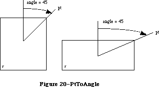 Figure 20–PtToAngle
The angle returned might be used as input to one of the procedures that manipulate arcs and wedges, as described below under “Graphic Operations on Arcs and Wedges”.
FUNCTION EqualRect (rect1,rect2: Rect) : BOOLEAN;
EqualRect compares the two given rectangles and returns TRUE if they’re equal or FALSE if not. The two rectangles must have identical boundary coordinates to be considered equal.
FUNCTION EmptyRect (r: Rect) : BOOLEAN;
EmptyRect returns TRUE if the given rectangle is an empty rectangle or FALSE if not. A rectangle is considered empty if the bottom coordinate is less than or equal to the top or the right coordinate is less than or equal to the left.
_______________________________________________________________________________
»Graphic Operations on Rectangles
See also the ScrollRect procedure under “Bit Transfer Operations”.
PROCEDURE FrameRect (r: Rect);
FrameRect draws an outline just inside the specified rectangle, using the current grafPort’s pen pattern, mode, and size. The outline is as wide as the pen width and as tall as the pen height. It’s drawn with the pnPat, according to the pattern transfer mode specified by pnMode. The pen location is not changed by this procedure.
If a region is open and being formed, the outside outline of the new rectangle is mathematically added to the region’s boundary.
PROCEDURE PaintRect (r: Rect);
PaintRect paints the specified rectangle with the current grafPort’s pen pattern and mode. The rectangle is filled with the pnPat, according to the pattern transfer mode specified by pnMode. The pen location is not changed by this procedure.
PROCEDURE EraseRect (r: Rect);
EraseRect paints the specified rectangle with the current grafPort’s background pattern bkPat (in patCopy mode). The grafPort’s pnPat and pnMode are ignored; the pen location is not changed.
PROCEDURE InvertRect (r: Rect);
Assembly-language note: The macro you invoke to call InvertRect from
assembly language is named _InverRect.
InvertRect inverts the pixels enclosed by the specified rectangle: Every white pixel becomes black and every black pixel becomes white. The grafPort’s pnPat, pnMode, and bkPat are all ignored; the pen location is not changed.
PROCEDURE FillRect (r: Rect; pat: Pattern);
FillRect fills the specified rectangle with the given pattern (in patCopy mode). The grafPort’s pnPat, pnMode, and bkPat are all ignored; the pen location is not changed.
_______________________________________________________________________________
»Graphic Operations on Ovals
Ovals are drawn inside rectangles that you specify. If you specify a square rectangle, QuickDraw draws a circle.
PROCEDURE FrameOval (r: Rect);
FrameOval draws an outline just inside the oval that fits inside the specified rectangle, using the current grafPort’s pen pattern, mode, and size. The outline is as wide as the pen width and as tall as the pen height. It’s drawn with the pnPat, according to the pattern transfer mode specified by pnMode. The pen location is not changed by this procedure.
If a region is open and being formed, the outside outline of the new oval is mathematically added to the region’s boundary.
PROCEDURE PaintOval (r: Rect);
PaintOval paints an oval just inside the specified rectangle with the current grafPort’s pen pattern and mode. The oval is filled with the pnPat, according to the pattern transfer mode specified by pnMode. The pen location is not changed by this procedure.
PROCEDURE EraseOval (r: Rect);
EraseOval paints an oval just inside the specified rectangle with the current grafPort’s background pattern bkPat (in patCopy mode). The grafPort’s pnPat and pnMode are ignored; the pen location is not changed.
PROCEDURE InvertOval (r: Rect);
InvertOval inverts the pixels enclosed by an oval just inside the specified rectangle: Every white pixel becomes black and every black pixel becomes white. The grafPort’s pnPat, pnMode, and bkPat are all ignored; the pen location is not changed.
PROCEDURE FillOval (r: Rect; pat: Pattern);
FillOval fills an oval just inside the specified rectangle with the given pattern (in patCopy mode). The grafPort’s pnPat, pnMode, and bkPat are all ignored; the pen location is not changed.
_______________________________________________________________________________
»Graphic Operations on Rounded-Corner Rectangles
PROCEDURE FrameRoundRect (r: Rect; ovalWidth,ovalHeight: INTEGER);
FrameRoundRect draws an outline just inside the specified rounded-corner rectangle, using the current grafPort’s pen pattern, mode, and size. OvalWidth and ovalHeight specify the diameters of curvature for the corners (see Figure 21). The outline is as wide as the pen width and as tall as the pen height.
It’s drawn with the pnPat, according to the pattern transfer mode specified by pnMode. The pen location is not changed by this procedure.
Figure 20–PtToAngle
The angle returned might be used as input to one of the procedures that manipulate arcs and wedges, as described below under “Graphic Operations on Arcs and Wedges”.
FUNCTION EqualRect (rect1,rect2: Rect) : BOOLEAN;
EqualRect compares the two given rectangles and returns TRUE if they’re equal or FALSE if not. The two rectangles must have identical boundary coordinates to be considered equal.
FUNCTION EmptyRect (r: Rect) : BOOLEAN;
EmptyRect returns TRUE if the given rectangle is an empty rectangle or FALSE if not. A rectangle is considered empty if the bottom coordinate is less than or equal to the top or the right coordinate is less than or equal to the left.
_______________________________________________________________________________
»Graphic Operations on Rectangles
See also the ScrollRect procedure under “Bit Transfer Operations”.
PROCEDURE FrameRect (r: Rect);
FrameRect draws an outline just inside the specified rectangle, using the current grafPort’s pen pattern, mode, and size. The outline is as wide as the pen width and as tall as the pen height. It’s drawn with the pnPat, according to the pattern transfer mode specified by pnMode. The pen location is not changed by this procedure.
If a region is open and being formed, the outside outline of the new rectangle is mathematically added to the region’s boundary.
PROCEDURE PaintRect (r: Rect);
PaintRect paints the specified rectangle with the current grafPort’s pen pattern and mode. The rectangle is filled with the pnPat, according to the pattern transfer mode specified by pnMode. The pen location is not changed by this procedure.
PROCEDURE EraseRect (r: Rect);
EraseRect paints the specified rectangle with the current grafPort’s background pattern bkPat (in patCopy mode). The grafPort’s pnPat and pnMode are ignored; the pen location is not changed.
PROCEDURE InvertRect (r: Rect);
Assembly-language note: The macro you invoke to call InvertRect from
assembly language is named _InverRect.
InvertRect inverts the pixels enclosed by the specified rectangle: Every white pixel becomes black and every black pixel becomes white. The grafPort’s pnPat, pnMode, and bkPat are all ignored; the pen location is not changed.
PROCEDURE FillRect (r: Rect; pat: Pattern);
FillRect fills the specified rectangle with the given pattern (in patCopy mode). The grafPort’s pnPat, pnMode, and bkPat are all ignored; the pen location is not changed.
_______________________________________________________________________________
»Graphic Operations on Ovals
Ovals are drawn inside rectangles that you specify. If you specify a square rectangle, QuickDraw draws a circle.
PROCEDURE FrameOval (r: Rect);
FrameOval draws an outline just inside the oval that fits inside the specified rectangle, using the current grafPort’s pen pattern, mode, and size. The outline is as wide as the pen width and as tall as the pen height. It’s drawn with the pnPat, according to the pattern transfer mode specified by pnMode. The pen location is not changed by this procedure.
If a region is open and being formed, the outside outline of the new oval is mathematically added to the region’s boundary.
PROCEDURE PaintOval (r: Rect);
PaintOval paints an oval just inside the specified rectangle with the current grafPort’s pen pattern and mode. The oval is filled with the pnPat, according to the pattern transfer mode specified by pnMode. The pen location is not changed by this procedure.
PROCEDURE EraseOval (r: Rect);
EraseOval paints an oval just inside the specified rectangle with the current grafPort’s background pattern bkPat (in patCopy mode). The grafPort’s pnPat and pnMode are ignored; the pen location is not changed.
PROCEDURE InvertOval (r: Rect);
InvertOval inverts the pixels enclosed by an oval just inside the specified rectangle: Every white pixel becomes black and every black pixel becomes white. The grafPort’s pnPat, pnMode, and bkPat are all ignored; the pen location is not changed.
PROCEDURE FillOval (r: Rect; pat: Pattern);
FillOval fills an oval just inside the specified rectangle with the given pattern (in patCopy mode). The grafPort’s pnPat, pnMode, and bkPat are all ignored; the pen location is not changed.
_______________________________________________________________________________
»Graphic Operations on Rounded-Corner Rectangles
PROCEDURE FrameRoundRect (r: Rect; ovalWidth,ovalHeight: INTEGER);
FrameRoundRect draws an outline just inside the specified rounded-corner rectangle, using the current grafPort’s pen pattern, mode, and size. OvalWidth and ovalHeight specify the diameters of curvature for the corners (see Figure 21). The outline is as wide as the pen width and as tall as the pen height.
It’s drawn with the pnPat, according to the pattern transfer mode specified by pnMode. The pen location is not changed by this procedure.
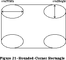 Figure 21–Rounded-Corner Rectangle
If a region is open and being formed, the outside outline of the new rounded-corner rectangle is mathematically added to the region’s boundary.
PROCEDURE PaintRoundRect (r: Rect; ovalWidth,ovalHeight: INTEGER);
PaintRoundRect paints the specified rounded-corner rectangle with the current grafPort’s pen pattern and mode. OvalWidth and ovalHeight specify the diameters of curvature for the corners.
The rounded-corner rectangle is filled with the pnPat, according to the pattern transfer mode specified by pnMode. The pen location is not changed by this procedure.
PROCEDURE EraseRoundRect (r: Rect; ovalWidth,ovalHeight: INTEGER);
EraseRoundRect paints the specified rounded-corner rectangle with the current grafPort’s background pattern bkPat (in patCopy mode).
OvalWidth and ovalHeight specify the diameters of curvature for the corners. The grafPort’s pnPat and pnMode are ignored; the pen location is not changed.
PROCEDURE InvertRoundRect (r: Rect; ovalWidth,ovalHeight: INTEGER);
Assembly-language note: The macro you invoke to call InvertRoundRect from
assembly language is named _InverRoundRect.
InvertRoundRect inverts the pixels enclosed by the specified rounded-corner rectangle: Every white pixel becomes black and every black pixel becomes white. OvalWidth and ovalHeight specify the diameters of curvature for the corners. The grafPort’s pnPat, pnMode, and bkPat are all ignored; the pen location is not changed.
PROCEDURE FillRoundRect (r: Rect; ovalWidth,ovalHeight: INTEGER;
pat: Pattern);
FillRoundRect fills the specified rounded-corner rectangle with the given pattern (in patCopy mode). OvalWidth and ovalHeight specify the diameters of curvature for the corners. The grafPort’s pnPat, pnMode, and bkPat are all ignored; the pen location is not changed.
_______________________________________________________________________________
»Graphic Operations on Arcs and Wedges
These procedures perform graphic operations on arcs and wedge-shaped sections of ovals. See also PtToAngle under “Calculations with Rectangles”.
PROCEDURE FrameArc (r: Rect; startAngle,arcAngle: INTEGER);
FrameArc draws an arc of the oval that fits inside the specified rectangle, using the current grafPort’s pen pattern, mode, and size. StartAngle indicates where the arc begins and is treated MOD 360. ArcAngle defines the extent of the arc. The angles are given in positive or negative degrees; a positive angle goes clockwise, while a negative angle goes counterclockwise. Zero degrees is at 12 o’clock high, 90 (or –270) is at 3 o’clock, 180 (or –180) is at 6 o’clock, and 270 (or –90) is at 9 o’clock. Other angles are measured relative to the enclosing rectangle: A line from the center of the rectangle through its top right corner is at 45 degrees, even if the rectangle isn’t square; a line through the bottom right corner is at 135 degrees, and so on (see Figure 22).
Figure 21–Rounded-Corner Rectangle
If a region is open and being formed, the outside outline of the new rounded-corner rectangle is mathematically added to the region’s boundary.
PROCEDURE PaintRoundRect (r: Rect; ovalWidth,ovalHeight: INTEGER);
PaintRoundRect paints the specified rounded-corner rectangle with the current grafPort’s pen pattern and mode. OvalWidth and ovalHeight specify the diameters of curvature for the corners.
The rounded-corner rectangle is filled with the pnPat, according to the pattern transfer mode specified by pnMode. The pen location is not changed by this procedure.
PROCEDURE EraseRoundRect (r: Rect; ovalWidth,ovalHeight: INTEGER);
EraseRoundRect paints the specified rounded-corner rectangle with the current grafPort’s background pattern bkPat (in patCopy mode).
OvalWidth and ovalHeight specify the diameters of curvature for the corners. The grafPort’s pnPat and pnMode are ignored; the pen location is not changed.
PROCEDURE InvertRoundRect (r: Rect; ovalWidth,ovalHeight: INTEGER);
Assembly-language note: The macro you invoke to call InvertRoundRect from
assembly language is named _InverRoundRect.
InvertRoundRect inverts the pixels enclosed by the specified rounded-corner rectangle: Every white pixel becomes black and every black pixel becomes white. OvalWidth and ovalHeight specify the diameters of curvature for the corners. The grafPort’s pnPat, pnMode, and bkPat are all ignored; the pen location is not changed.
PROCEDURE FillRoundRect (r: Rect; ovalWidth,ovalHeight: INTEGER;
pat: Pattern);
FillRoundRect fills the specified rounded-corner rectangle with the given pattern (in patCopy mode). OvalWidth and ovalHeight specify the diameters of curvature for the corners. The grafPort’s pnPat, pnMode, and bkPat are all ignored; the pen location is not changed.
_______________________________________________________________________________
»Graphic Operations on Arcs and Wedges
These procedures perform graphic operations on arcs and wedge-shaped sections of ovals. See also PtToAngle under “Calculations with Rectangles”.
PROCEDURE FrameArc (r: Rect; startAngle,arcAngle: INTEGER);
FrameArc draws an arc of the oval that fits inside the specified rectangle, using the current grafPort’s pen pattern, mode, and size. StartAngle indicates where the arc begins and is treated MOD 360. ArcAngle defines the extent of the arc. The angles are given in positive or negative degrees; a positive angle goes clockwise, while a negative angle goes counterclockwise. Zero degrees is at 12 o’clock high, 90 (or –270) is at 3 o’clock, 180 (or –180) is at 6 o’clock, and 270 (or –90) is at 9 o’clock. Other angles are measured relative to the enclosing rectangle: A line from the center of the rectangle through its top right corner is at 45 degrees, even if the rectangle isn’t square; a line through the bottom right corner is at 135 degrees, and so on (see Figure 22).
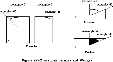 Figure 22–Operations on Arcs and Wedges
The arc is as wide as the pen width and as tall as the pen height. It’s drawn with the pnPat, according to the pattern transfer mode specified by pnMode. The pen location is not changed by this procedure.
Warning: FrameArc differs from other QuickDraw routines that frame shapes
in that the arc is not mathematically added to the boundary of a
region that’s open and being formed.
Note: QuickDraw doesn’t provide a routine for drawing an outlined wedge
of an oval.
PROCEDURE PaintArc (r: Rect; startAngle,arcAngle: INTEGER);
PaintArc paints a wedge of the oval just inside the specified rectangle with the current grafPort’s pen pattern and mode. StartAngle and arcAngle define the arc of the wedge as in FrameArc. The wedge is filled with the pnPat, according to the pattern transfer mode specified by pnMode. The pen location is not changed by this procedure.
PROCEDURE EraseArc (r: Rect; startAngle,arcAngle: INTEGER);
EraseArc paints a wedge of the oval just inside the specified rectangle with the current grafPort’s background pattern bkPat (in patCopy mode). StartAngle and arcAngle define the arc of the wedge as in FrameArc. The grafPort’s pnPat and pnMode are ignored; the pen location is not changed.
PROCEDURE InvertArc (r: Rect; startAngle,arcAngle: INTEGER);
InvertArc inverts the pixels enclosed by a wedge of the oval just inside the specified rectangle: Every white pixel becomes black and every black pixel becomes white. StartAngle and arcAngle define the arc of the wedge as in FrameArc. The grafPort’s pnPat, pnMode, and bkPat are all ignored; the pen location is not changed.
PROCEDURE FillArc (r: Rect; startAngle,arcAngle: INTEGER; pat: Pattern);
FillArc fills a wedge of the oval just inside the specified rectangle with the given pattern (in patCopy mode). StartAngle and arcAngle define the arc of the wedge as in FrameArc. The grafPort’s pnPat, pnMode, and bkPat are all ignored; the pen location is not changed.
_______________________________________________________________________________
»Calculations with Regions
Remember that if the parameters to a calculation procedure were defined in different grafPorts, you must first adjust them to global coordinates.
FUNCTION NewRgn : RgnHandle;
NewRgn allocates space for a new, variable-size region, initializes it to the empty region defined by the rectangle (0,0)(0,0), and returns a handle to the new region.
Warning: Only this function creates new regions; all other routines just
alter the size and shape of existing regions. Before a region’s
handle can be passed to any drawing or calculation routine, space
must already have been allocated for the region.
PROCEDURE OpenRgn;
OpenRgn tells QuickDraw to allocate temporary space and start saving lines and framed shapes for later processing as a region definition. While a region is open, all calls to Line, LineTo, and the procedures that draw framed shapes
(except arcs) affect the outline of the region. Only the line endpoints and shape boundaries affect the region definition; the pen mode, pattern, and size do not affect it. In fact, OpenRgn calls HidePen, so no drawing occurs on the screen while the region is open (unless you called ShowPen just after OpenRgn, or you called ShowPen previously without balancing it by a call to HidePen). Since the pen hangs below and to the right of the pen location, drawing lines with even the smallest pen will change bits that lie outside the region you define.
The outline of a region is mathematically defined and infinitely thin, and separates the bit image into two groups of bits: Those within the region and those outside it. A region should consist of one or more closed loops. Each framed shape itself constitutes a loop. Any lines drawn with Line or LineTo should connect with each other or with a framed shape. Even though the on-screen presentation of a region is clipped, the definition of a region is not; you can define a region anywhere on the coordinate plane with complete disregard for the location of various grafPort entities on that plane.
When a region is open, the current grafPort’s rgnSave field contains a handle to information related to the region definition. If you want to temporarily disable the collection of lines and shapes, you can save the current value of this field, set the field to NIL, and later restore the saved value to resume the region definition. Also, calling SetPort while a region is being formed will discontinue formation of the region until another call to SetPort resets the region’s original grafPort.
Warning: Do not call OpenRgn while another region or polygon is already
open. All open regions but the most recent will behave strangely.
Note: Regions are limited to 32K bytes.
PROCEDURE CloseRgn (dstRgn: RgnHandle);
CloseRgn stops the collection of lines and framed shapes, organizes them into a region definition, and saves the resulting region in the region indicated by dstRgn. CloseRgn does not create the destination region; space must already have been allocated for it. You should perform one and only one CloseRgn for every OpenRgn. CloseRgn calls ShowPen, balancing the HidePen call made by OpenRgn.
Here’s an example of how to create and open a region, define a barbell shape, close the region, draw it, and dispose of it:
barbell := NewRgn; {create a new region}
OpenRgn; {begin collecting stuff}
SetRect(tempRect,20,20,30,50); {form the left weight}
FrameOval(tempRect);
SetRect(tempRect,25,30,85,40); {form the bar}
FrameRect(tempRect);
SetRect(tempRect,80,20,90,50); {form the right weight}
FrameOval(tempRect);
CloseRgn(barbell); {we're done; save in barbell}
FillRgn(barbell,black); {draw it on the screen}
DisposeRgn(barbell) {dispose of the region}
PROCEDURE DisposeRgn (rgn: RgnHandle);
Assembly-language note: The macro you invoke to call DisposeRgn from
assembly language is named _DisposRgn.
DisposeRgn releases the memory occupied by the given region. Use this only after you’re completely through with a temporary region.
PROCEDURE CopyRgn (srcRgn,dstRgn: RgnHandle);
CopyRgn copies the mathematical structure of srcRgn into dstRgn; that is, it makes a duplicate copy of srcRgn. Once this is done, srcRgn may be altered (or even disposed of) without affecting dstRgn. CopyRgn does not create the destination region; space must already have been allocated for it.
PROCEDURE SetEmptyRgn (rgn: RgnHandle);
SetEmptyRgn destroys the previous structure of the given region, then sets the new structure to the empty region defined by the rectangle (0,0)(0,0).
PROCEDURE SetRectRgn (rgn: RgnHandle; left,top,right,bottom: INTEGER);
Assembly-language note: The macro you invoke to call SetRectRgn from
assembly language is named _SetRecRgn.
SetRectRgn destroys the previous structure of the given region, and then sets the new structure to the rectangle specified by left, top, right, and bottom.
If the specified rectangle is empty (that is, right<=left or bottom<=top), the region is set to the empty region defined by the rectangle (0,0)(0,0).
PROCEDURE RectRgn (rgn: RgnHandle; r: Rect);
RectRgn destroys the previous structure of the given region, and then sets the new structure to the rectangle specified by r. This is the same as SetRectRgn, except the given rectangle is defined by a rectangle rather than by four boundary coordinates.
PROCEDURE OffsetRgn (rgn: RgnHandle; dh,dv: INTEGER);
Assembly-language note: The macro you invoke to call OffsetRgn from
assembly language is named _OfsetRgn.
OffsetRgn moves the region on the coordinate plane, a distance of dh horizontally and dv vertically. This doesn’t affect the screen unless you subsequently call a routine to draw the region. If dh and dv are positive, the movement is to the right and down; if either is negative, the corresponding movement is in the opposite direction. The region retains its size and shape.
Note: OffsetRgn is an especially efficient operation, because most of
the data defining a region is stored relative to rgnBBox and so
isn’t actually changed by OffsetRgn.
PROCEDURE InsetRgn (rgn: RgnHandle; dh,dv: INTEGER);
InsetRgn shrinks or expands the region. All points on the region boundary are moved inwards a distance of dv vertically and dh horizontally; if dh or dv is negative, the points are moved outwards in that direction. InsetRgn leaves the region “centered” at the same position, but moves the outline in (for positive values of dh and dv) or out (for negative values of dh and dv). InsetRgn of a rectangular region works just like InsetRect.
Note: InsetRgn temporarily uses heap space that’s twice the size of
the original region.
PROCEDURE SectRgn (srcRgnA,srcRgnB,dstRgn: RgnHandle);
SectRgn calculates the intersection of two regions and places the intersection in a third region. This does not create the destination region; space must already have been allocated for it. The destination region can be one of the source regions, if desired.
If the regions do not intersect, or one of the regions is empty, the destination is set to the empty region defined by the rectangle (0,0)(0,0).
Note: SectRgn may temporarily use heap space that’s twice the size of
the two input regions.
PROCEDURE UnionRgn (srcRgnA,srcRgnB,dstRgn: RgnHandle);
UnionRgn calculates the union of two regions and places the union in a third region. This does not create the destination region; space must already have been allocated for it. The destination region can be one of the source regions, if desired.
If both regions are empty, the destination is set to the empty region defined by the rectangle (0,0)(0,0).
Note: UnionRgn may temporarily use heap space that’s twice the size of
the two input regions.
PROCEDURE DiffRgn (srcRgnA,srcRgnB,dstRgn: RgnHandle);
DiffRgn subtracts srcRgnB from srcRgnA and places the difference in a third region. This does not create the destination region; space must already have been allocated for it. The destination region can be one of the source regions, if desired.
If the first source region is empty, the destination is set to the empty region defined by the rectangle (0,0)(0,0).
Note: DiffRgn may temporarily use heap space that’s twice the size of
the two input regions.
PROCEDURE XorRgn (srcRgnA,srcRgnB,dstRgn: RgnHandle);
XorRgn calculates the difference between the union and the intersection of srcRgnA and srcRgnB and places the result in dstRgn. This does not create the destination region; space must already have been allocated for it. The destination region can be one of the source regions, if desired.
If the regions are coincident, the destination is set to the empty region defined by the rectangle (0,0)(0,0).
Note: XorRgn may temporarily use heap space that’s twice the size of
the two input regions.
FUNCTION PtInRgn (pt: Point; rgn: RgnHandle) : BOOLEAN;
PtInRgn checks whether the pixel below and to the right of the given coordinate point is within the specified region, and returns TRUE if so or FALSE if not.
FUNCTION RectInRgn (r: Rect; rgn: RgnHandle) : BOOLEAN;
RectInRgn checks whether the given rectangle intersects the specified region, and returns TRUE if the intersection encloses at least one bit or FALSE if not.
Note: RectInRgn will sometimes return TRUE when the rectangle merely
intersects the region’s enclosing rectangle. If you need to know
exactly whether a given rectangle intersects the actual region,
you can use RectRgn to set the rectangle to a region, and call
SectRgn to see whether the two regions intersect: If the result
of SectRgn is an empty region, then the rectangle doesn’t intersect
the region.
FUNCTION EqualRgn (rgnA,rgnB: RgnHandle) : BOOLEAN;
EqualRgn compares the two given regions and returns TRUE if they’re equal or FALSE if not. The two regions must have identical sizes, shapes, and locations to be considered equal. Any two empty regions are always equal.
FUNCTION EmptyRgn (rgn: RgnHandle) : BOOLEAN;
EmptyRgn returns TRUE if the region is an empty region or FALSE if not. Some of the circumstances in which an empty region can be created are: a NewRgn call; a CopyRgn of an empty region; a SetRectRgn or RectRgn with an empty rectangle as an argument; CloseRgn without a previous OpenRgn or with no drawing after an OpenRgn; OffsetRgn of an empty region; InsetRgn with an empty region or too large an inset; SectRgn of nonintersecting regions; UnionRgn of two empty regions; and DiffRgn or XorRgn of two identical or nonintersecting regions.
_______________________________________________________________________________
»Graphic Operations on Regions
These routines all depend on the coordinate system of the current grafPort. If a region is drawn in a different grafPort than the one in which it was defined, it may not appear in the proper position in the port.
PROCEDURE FrameRgn (rgn: RgnHandle);
FrameRgn draws an outline just inside the specified region, using the current grafPort’s pen pattern, mode, and size. The outline is as wide as the pen width and as tall as the pen height. It’s drawn with the pnPat, according to the pattern transfer mode specified by pnMode. The outline will never go outside the region boundary. The pen location is not changed by this procedure.
If a region is open and being formed, the outside outline of the region being framed is mathematically added to that region’s boundary.
Note: FrameRgn actually does a CopyRgn, an InsetRgn, and a DiffRgn;
it may temporarily use heap space that’s three times the size
of the original region.
PROCEDURE PaintRgn (rgn: RgnHandle);
PaintRgn paints the specified region with the current grafPort’s pen pattern and pen mode. The region is filled with the pnPat, according to the pattern transfer mode specified by pnMode. The pen location is not changed by this procedure.
PROCEDURE EraseRgn (rgn: RgnHandle);
EraseRgn paints the specified region with the current grafPort’s background pattern bkPat (in patCopy mode). The grafPort’s pnPat and pnMode are ignored; the pen location is not changed.
PROCEDURE InvertRgn (rgn: RgnHandle);
Assembly-language note: The macro you invoke to call InvertRgn from
assembly language is named _InverRgn.
InvertRgn inverts the pixels enclosed by the specified region: Every white pixel becomes black and every black pixel becomes white. The grafPort’s pnPat, pnMode, and bkPat are all ignored; the pen location is not changed.
PROCEDURE FillRgn (rgn: RgnHandle; pat: Pattern);
FillRgn fills the specified region with the given pattern (in patCopy mode). The grafPort’s pnPat, pnMode, and bkPat are all ignored; the pen location is not changed.
_______________________________________________________________________________
»Bit Map Operations
PROCEDURE ScrollRect (r: Rect; dh,dv: INTEGER; updateRgn: RgnHandle);
ScrollRect shifts (“scrolls”) the bits that are inside the intersection of the specified rectangle and the visRgn, clipRgn, portRect, and portBits.bounds of the current grafPort. No other bits are affected. The bits are shifted a distance of dh horizontally and dv vertically. The positive directions are
to the right and down. Bits that are shifted out of the scroll area are
lost—they’re neither placed outside the area nor saved. The space created by the scroll is filled with the grafPort’s background pattern (thePort^.bkPat), and the updateRgn is changed to this filled area (see Figure 23).
Figure 22–Operations on Arcs and Wedges
The arc is as wide as the pen width and as tall as the pen height. It’s drawn with the pnPat, according to the pattern transfer mode specified by pnMode. The pen location is not changed by this procedure.
Warning: FrameArc differs from other QuickDraw routines that frame shapes
in that the arc is not mathematically added to the boundary of a
region that’s open and being formed.
Note: QuickDraw doesn’t provide a routine for drawing an outlined wedge
of an oval.
PROCEDURE PaintArc (r: Rect; startAngle,arcAngle: INTEGER);
PaintArc paints a wedge of the oval just inside the specified rectangle with the current grafPort’s pen pattern and mode. StartAngle and arcAngle define the arc of the wedge as in FrameArc. The wedge is filled with the pnPat, according to the pattern transfer mode specified by pnMode. The pen location is not changed by this procedure.
PROCEDURE EraseArc (r: Rect; startAngle,arcAngle: INTEGER);
EraseArc paints a wedge of the oval just inside the specified rectangle with the current grafPort’s background pattern bkPat (in patCopy mode). StartAngle and arcAngle define the arc of the wedge as in FrameArc. The grafPort’s pnPat and pnMode are ignored; the pen location is not changed.
PROCEDURE InvertArc (r: Rect; startAngle,arcAngle: INTEGER);
InvertArc inverts the pixels enclosed by a wedge of the oval just inside the specified rectangle: Every white pixel becomes black and every black pixel becomes white. StartAngle and arcAngle define the arc of the wedge as in FrameArc. The grafPort’s pnPat, pnMode, and bkPat are all ignored; the pen location is not changed.
PROCEDURE FillArc (r: Rect; startAngle,arcAngle: INTEGER; pat: Pattern);
FillArc fills a wedge of the oval just inside the specified rectangle with the given pattern (in patCopy mode). StartAngle and arcAngle define the arc of the wedge as in FrameArc. The grafPort’s pnPat, pnMode, and bkPat are all ignored; the pen location is not changed.
_______________________________________________________________________________
»Calculations with Regions
Remember that if the parameters to a calculation procedure were defined in different grafPorts, you must first adjust them to global coordinates.
FUNCTION NewRgn : RgnHandle;
NewRgn allocates space for a new, variable-size region, initializes it to the empty region defined by the rectangle (0,0)(0,0), and returns a handle to the new region.
Warning: Only this function creates new regions; all other routines just
alter the size and shape of existing regions. Before a region’s
handle can be passed to any drawing or calculation routine, space
must already have been allocated for the region.
PROCEDURE OpenRgn;
OpenRgn tells QuickDraw to allocate temporary space and start saving lines and framed shapes for later processing as a region definition. While a region is open, all calls to Line, LineTo, and the procedures that draw framed shapes
(except arcs) affect the outline of the region. Only the line endpoints and shape boundaries affect the region definition; the pen mode, pattern, and size do not affect it. In fact, OpenRgn calls HidePen, so no drawing occurs on the screen while the region is open (unless you called ShowPen just after OpenRgn, or you called ShowPen previously without balancing it by a call to HidePen). Since the pen hangs below and to the right of the pen location, drawing lines with even the smallest pen will change bits that lie outside the region you define.
The outline of a region is mathematically defined and infinitely thin, and separates the bit image into two groups of bits: Those within the region and those outside it. A region should consist of one or more closed loops. Each framed shape itself constitutes a loop. Any lines drawn with Line or LineTo should connect with each other or with a framed shape. Even though the on-screen presentation of a region is clipped, the definition of a region is not; you can define a region anywhere on the coordinate plane with complete disregard for the location of various grafPort entities on that plane.
When a region is open, the current grafPort’s rgnSave field contains a handle to information related to the region definition. If you want to temporarily disable the collection of lines and shapes, you can save the current value of this field, set the field to NIL, and later restore the saved value to resume the region definition. Also, calling SetPort while a region is being formed will discontinue formation of the region until another call to SetPort resets the region’s original grafPort.
Warning: Do not call OpenRgn while another region or polygon is already
open. All open regions but the most recent will behave strangely.
Note: Regions are limited to 32K bytes.
PROCEDURE CloseRgn (dstRgn: RgnHandle);
CloseRgn stops the collection of lines and framed shapes, organizes them into a region definition, and saves the resulting region in the region indicated by dstRgn. CloseRgn does not create the destination region; space must already have been allocated for it. You should perform one and only one CloseRgn for every OpenRgn. CloseRgn calls ShowPen, balancing the HidePen call made by OpenRgn.
Here’s an example of how to create and open a region, define a barbell shape, close the region, draw it, and dispose of it:
barbell := NewRgn; {create a new region}
OpenRgn; {begin collecting stuff}
SetRect(tempRect,20,20,30,50); {form the left weight}
FrameOval(tempRect);
SetRect(tempRect,25,30,85,40); {form the bar}
FrameRect(tempRect);
SetRect(tempRect,80,20,90,50); {form the right weight}
FrameOval(tempRect);
CloseRgn(barbell); {we're done; save in barbell}
FillRgn(barbell,black); {draw it on the screen}
DisposeRgn(barbell) {dispose of the region}
PROCEDURE DisposeRgn (rgn: RgnHandle);
Assembly-language note: The macro you invoke to call DisposeRgn from
assembly language is named _DisposRgn.
DisposeRgn releases the memory occupied by the given region. Use this only after you’re completely through with a temporary region.
PROCEDURE CopyRgn (srcRgn,dstRgn: RgnHandle);
CopyRgn copies the mathematical structure of srcRgn into dstRgn; that is, it makes a duplicate copy of srcRgn. Once this is done, srcRgn may be altered (or even disposed of) without affecting dstRgn. CopyRgn does not create the destination region; space must already have been allocated for it.
PROCEDURE SetEmptyRgn (rgn: RgnHandle);
SetEmptyRgn destroys the previous structure of the given region, then sets the new structure to the empty region defined by the rectangle (0,0)(0,0).
PROCEDURE SetRectRgn (rgn: RgnHandle; left,top,right,bottom: INTEGER);
Assembly-language note: The macro you invoke to call SetRectRgn from
assembly language is named _SetRecRgn.
SetRectRgn destroys the previous structure of the given region, and then sets the new structure to the rectangle specified by left, top, right, and bottom.
If the specified rectangle is empty (that is, right<=left or bottom<=top), the region is set to the empty region defined by the rectangle (0,0)(0,0).
PROCEDURE RectRgn (rgn: RgnHandle; r: Rect);
RectRgn destroys the previous structure of the given region, and then sets the new structure to the rectangle specified by r. This is the same as SetRectRgn, except the given rectangle is defined by a rectangle rather than by four boundary coordinates.
PROCEDURE OffsetRgn (rgn: RgnHandle; dh,dv: INTEGER);
Assembly-language note: The macro you invoke to call OffsetRgn from
assembly language is named _OfsetRgn.
OffsetRgn moves the region on the coordinate plane, a distance of dh horizontally and dv vertically. This doesn’t affect the screen unless you subsequently call a routine to draw the region. If dh and dv are positive, the movement is to the right and down; if either is negative, the corresponding movement is in the opposite direction. The region retains its size and shape.
Note: OffsetRgn is an especially efficient operation, because most of
the data defining a region is stored relative to rgnBBox and so
isn’t actually changed by OffsetRgn.
PROCEDURE InsetRgn (rgn: RgnHandle; dh,dv: INTEGER);
InsetRgn shrinks or expands the region. All points on the region boundary are moved inwards a distance of dv vertically and dh horizontally; if dh or dv is negative, the points are moved outwards in that direction. InsetRgn leaves the region “centered” at the same position, but moves the outline in (for positive values of dh and dv) or out (for negative values of dh and dv). InsetRgn of a rectangular region works just like InsetRect.
Note: InsetRgn temporarily uses heap space that’s twice the size of
the original region.
PROCEDURE SectRgn (srcRgnA,srcRgnB,dstRgn: RgnHandle);
SectRgn calculates the intersection of two regions and places the intersection in a third region. This does not create the destination region; space must already have been allocated for it. The destination region can be one of the source regions, if desired.
If the regions do not intersect, or one of the regions is empty, the destination is set to the empty region defined by the rectangle (0,0)(0,0).
Note: SectRgn may temporarily use heap space that’s twice the size of
the two input regions.
PROCEDURE UnionRgn (srcRgnA,srcRgnB,dstRgn: RgnHandle);
UnionRgn calculates the union of two regions and places the union in a third region. This does not create the destination region; space must already have been allocated for it. The destination region can be one of the source regions, if desired.
If both regions are empty, the destination is set to the empty region defined by the rectangle (0,0)(0,0).
Note: UnionRgn may temporarily use heap space that’s twice the size of
the two input regions.
PROCEDURE DiffRgn (srcRgnA,srcRgnB,dstRgn: RgnHandle);
DiffRgn subtracts srcRgnB from srcRgnA and places the difference in a third region. This does not create the destination region; space must already have been allocated for it. The destination region can be one of the source regions, if desired.
If the first source region is empty, the destination is set to the empty region defined by the rectangle (0,0)(0,0).
Note: DiffRgn may temporarily use heap space that’s twice the size of
the two input regions.
PROCEDURE XorRgn (srcRgnA,srcRgnB,dstRgn: RgnHandle);
XorRgn calculates the difference between the union and the intersection of srcRgnA and srcRgnB and places the result in dstRgn. This does not create the destination region; space must already have been allocated for it. The destination region can be one of the source regions, if desired.
If the regions are coincident, the destination is set to the empty region defined by the rectangle (0,0)(0,0).
Note: XorRgn may temporarily use heap space that’s twice the size of
the two input regions.
FUNCTION PtInRgn (pt: Point; rgn: RgnHandle) : BOOLEAN;
PtInRgn checks whether the pixel below and to the right of the given coordinate point is within the specified region, and returns TRUE if so or FALSE if not.
FUNCTION RectInRgn (r: Rect; rgn: RgnHandle) : BOOLEAN;
RectInRgn checks whether the given rectangle intersects the specified region, and returns TRUE if the intersection encloses at least one bit or FALSE if not.
Note: RectInRgn will sometimes return TRUE when the rectangle merely
intersects the region’s enclosing rectangle. If you need to know
exactly whether a given rectangle intersects the actual region,
you can use RectRgn to set the rectangle to a region, and call
SectRgn to see whether the two regions intersect: If the result
of SectRgn is an empty region, then the rectangle doesn’t intersect
the region.
FUNCTION EqualRgn (rgnA,rgnB: RgnHandle) : BOOLEAN;
EqualRgn compares the two given regions and returns TRUE if they’re equal or FALSE if not. The two regions must have identical sizes, shapes, and locations to be considered equal. Any two empty regions are always equal.
FUNCTION EmptyRgn (rgn: RgnHandle) : BOOLEAN;
EmptyRgn returns TRUE if the region is an empty region or FALSE if not. Some of the circumstances in which an empty region can be created are: a NewRgn call; a CopyRgn of an empty region; a SetRectRgn or RectRgn with an empty rectangle as an argument; CloseRgn without a previous OpenRgn or with no drawing after an OpenRgn; OffsetRgn of an empty region; InsetRgn with an empty region or too large an inset; SectRgn of nonintersecting regions; UnionRgn of two empty regions; and DiffRgn or XorRgn of two identical or nonintersecting regions.
_______________________________________________________________________________
»Graphic Operations on Regions
These routines all depend on the coordinate system of the current grafPort. If a region is drawn in a different grafPort than the one in which it was defined, it may not appear in the proper position in the port.
PROCEDURE FrameRgn (rgn: RgnHandle);
FrameRgn draws an outline just inside the specified region, using the current grafPort’s pen pattern, mode, and size. The outline is as wide as the pen width and as tall as the pen height. It’s drawn with the pnPat, according to the pattern transfer mode specified by pnMode. The outline will never go outside the region boundary. The pen location is not changed by this procedure.
If a region is open and being formed, the outside outline of the region being framed is mathematically added to that region’s boundary.
Note: FrameRgn actually does a CopyRgn, an InsetRgn, and a DiffRgn;
it may temporarily use heap space that’s three times the size
of the original region.
PROCEDURE PaintRgn (rgn: RgnHandle);
PaintRgn paints the specified region with the current grafPort’s pen pattern and pen mode. The region is filled with the pnPat, according to the pattern transfer mode specified by pnMode. The pen location is not changed by this procedure.
PROCEDURE EraseRgn (rgn: RgnHandle);
EraseRgn paints the specified region with the current grafPort’s background pattern bkPat (in patCopy mode). The grafPort’s pnPat and pnMode are ignored; the pen location is not changed.
PROCEDURE InvertRgn (rgn: RgnHandle);
Assembly-language note: The macro you invoke to call InvertRgn from
assembly language is named _InverRgn.
InvertRgn inverts the pixels enclosed by the specified region: Every white pixel becomes black and every black pixel becomes white. The grafPort’s pnPat, pnMode, and bkPat are all ignored; the pen location is not changed.
PROCEDURE FillRgn (rgn: RgnHandle; pat: Pattern);
FillRgn fills the specified region with the given pattern (in patCopy mode). The grafPort’s pnPat, pnMode, and bkPat are all ignored; the pen location is not changed.
_______________________________________________________________________________
»Bit Map Operations
PROCEDURE ScrollRect (r: Rect; dh,dv: INTEGER; updateRgn: RgnHandle);
ScrollRect shifts (“scrolls”) the bits that are inside the intersection of the specified rectangle and the visRgn, clipRgn, portRect, and portBits.bounds of the current grafPort. No other bits are affected. The bits are shifted a distance of dh horizontally and dv vertically. The positive directions are
to the right and down. Bits that are shifted out of the scroll area are
lost—they’re neither placed outside the area nor saved. The space created by the scroll is filled with the grafPort’s background pattern (thePort^.bkPat), and the updateRgn is changed to this filled area (see Figure 23).
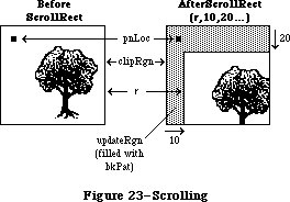 Figure 23–Scrolling
ScrollRect doesn’t change the coordinate system of the grafPort, it simply moves the entire document to different coordinates. Notice that ScrollRect doesn’t move the pen and the clipRgn. However, since the document has moved, they’re in a different position relative to the document.
To restore the coordinates of the document to what they were before the ScrollRect, you can use the SetOrigin procedure. In Figure 23, suppose that before the ScrollRect the top left corner of the document was at coordinates
(100,100). After ScrollRect(r,10,20...), the coordinates of the document are offset by the specified values. You could call SetOrigin(90,80) to offset the coordinate system to compensate for the scroll (see Figure 14 in the
“Coordinates in GrafPorts” section for an illustration). The document itself doesn’t move as a result of SetOrigin, but the pen and clipRgn move down and to the right, and are restored to their original position relative to the document. Notice that updateRgn will still need to be redrawn.
PROCEDURE CopyBits (srcBits,dstBits: BitMap; srcRect,dstRect: Rect;
mode: INTEGER; maskRgn: RgnHandle);
CopyBits transfers a bit image between any two bit maps and clips the result to the area specified by the maskRgn parameter. The transfer may be performed in any of the eight source transfer modes. The result is always clipped to the maskRgn and the boundary rectangle of the destination bit map; if the destination bit map is the current grafPort’s portBits, it’s also clipped to the intersection of the grafPort’s clipRgn and visRgn. If you don’t want to clip to a maskRgn, just pass NIL for the maskRgn parameter. The dstRect and maskRgn coordinates are in terms of the dstBits.bounds coordinate system, and the srcRect coordinates are in terms of the srcBits.bounds coordinates.
Warning: If you perform a CopyBits between two grafPorts that overlap,
you must first convert to global coordinates, and then specify
screenBits for both srcBits and dstBits.
The bits enclosed by the source rectangle are transferred into the destination rectangle according to the rules of the chosen mode. The source transfer modes are as follows:
srcCopy notSrcCopy
srcOr notSrcXor
srcXor notSrcOr
srcBic notSrcBic
The source rectangle is completely aligned with the destination rectangle; if the rectangles are of different sizes, the bit image is expanded or shrunk as necessary to fit the destination rectangle. For example, if the bit image is a circle in a square source rectangle, and the destination rectangle is not square, the bit image appears as an oval in the destination (see Figure 24).
Figure 23–Scrolling
ScrollRect doesn’t change the coordinate system of the grafPort, it simply moves the entire document to different coordinates. Notice that ScrollRect doesn’t move the pen and the clipRgn. However, since the document has moved, they’re in a different position relative to the document.
To restore the coordinates of the document to what they were before the ScrollRect, you can use the SetOrigin procedure. In Figure 23, suppose that before the ScrollRect the top left corner of the document was at coordinates
(100,100). After ScrollRect(r,10,20...), the coordinates of the document are offset by the specified values. You could call SetOrigin(90,80) to offset the coordinate system to compensate for the scroll (see Figure 14 in the
“Coordinates in GrafPorts” section for an illustration). The document itself doesn’t move as a result of SetOrigin, but the pen and clipRgn move down and to the right, and are restored to their original position relative to the document. Notice that updateRgn will still need to be redrawn.
PROCEDURE CopyBits (srcBits,dstBits: BitMap; srcRect,dstRect: Rect;
mode: INTEGER; maskRgn: RgnHandle);
CopyBits transfers a bit image between any two bit maps and clips the result to the area specified by the maskRgn parameter. The transfer may be performed in any of the eight source transfer modes. The result is always clipped to the maskRgn and the boundary rectangle of the destination bit map; if the destination bit map is the current grafPort’s portBits, it’s also clipped to the intersection of the grafPort’s clipRgn and visRgn. If you don’t want to clip to a maskRgn, just pass NIL for the maskRgn parameter. The dstRect and maskRgn coordinates are in terms of the dstBits.bounds coordinate system, and the srcRect coordinates are in terms of the srcBits.bounds coordinates.
Warning: If you perform a CopyBits between two grafPorts that overlap,
you must first convert to global coordinates, and then specify
screenBits for both srcBits and dstBits.
The bits enclosed by the source rectangle are transferred into the destination rectangle according to the rules of the chosen mode. The source transfer modes are as follows:
srcCopy notSrcCopy
srcOr notSrcXor
srcXor notSrcOr
srcBic notSrcBic
The source rectangle is completely aligned with the destination rectangle; if the rectangles are of different sizes, the bit image is expanded or shrunk as necessary to fit the destination rectangle. For example, if the bit image is a circle in a square source rectangle, and the destination rectangle is not square, the bit image appears as an oval in the destination (see Figure 24).
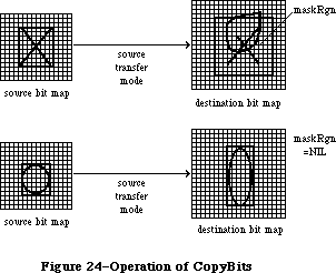 Figure 24–Operation of CopyBits
PROCEDURE SeedFill (srcPtr,dstPtr: Ptr;
srcRow,dstRow,height,words,seedH,seedV: INTEGER);
Given a source bit image, SeedFill computes a destination bit image with 1’s only in the pixels where paint can leak from the starting seed point, like the MacPaint paint-bucket tool. SeedH and seedV specify horizontal and vertical offsets, in pixels, from the beginning of the data pointed to by dstPtr, determining how far into the destination bit image filling should begin. Calls to SeedFill are not clipped to the current port and are not stored into QuickDraw pictures.
PROCEDURE CalcMask (srcPtr,dstPtr: Ptr; srcRow,dstRow,height, words: INTEGER);
Given a source bit image, CalcMask computes a destination bit image with 1’s only in the pixels where paint could not leak from any of the outer edges, like the MacPaint lasso tool. Calls to CalcMask are not clipped to the current port and are not stored into QuickDraw pictures.
PROCEDURE CopyMask (srcBits,maskBits,dstBits: BitMap;
srcRect, maskRect,dstRect: Rect);
CopyMask is a new version of the CopyBits procedure; it transfers a bit image from the source bitmap to the destination bitmap only where the corresponding bit of the mask rectangle is a 1. (Note that the mask is specified as a rectangle instead of as a handle to a region.) It can be used along with CalcMask to implement the lasso copy as in MacPaint; it’s also useful for drawing icons. CopyMask doesn’t check for overlap between the source and destination bitmaps, doesn’t stretch the bit image, and doesn’t store into QuickDraw pictures. CopyMask does, however, respect the current port’s visRgn and clipRgn if dstBits is the portBits of the current grafPort.
_______________________________________________________________________________
»Pictures
FUNCTION OpenPicture (picFrame: Rect) : PicHandle;
OpenPicture returns a handle to a new picture that has the given rectangle as its picture frame, and tells QuickDraw to start saving as the picture definition all calls to drawing routines and all picture comments (if any).
OpenPicture calls HidePen, so no drawing occurs on the screen while the picture is open (unless you call ShowPen just after OpenPicture, or you called ShowPen previously without balancing it by a call to HidePen).
When a picture is open, the current grafPort’s picSave field contains a handle to information related to the picture definition. If you want to temporarily disable the collection of routine calls and picture comments, you can save the current value of this field, set the field to NIL, and later restore the saved value to resume the picture definition.
Warning: Do not call OpenPicture while another picture is already open.
Warning: A grafPort’s clipRgn is initialized to an arbitrarily large
region. You should always change the clipRgn to a smaller
region before calling OpenPicture, or no drawing may occur
when you call DrawPicture.
PROCEDURE ClosePicture;
ClosePicture tells QuickDraw to stop saving routine calls and picture comments as the definition of the currently open picture. You should perform one and only one ClosePicture for every OpenPicture. ClosePicture calls ShowPen, balancing the HidePen call made by OpenPicture.
PROCEDURE PicComment (kind,dataSize: INTEGER; dataHandle: Handle);
PicComment inserts the specified comment into the definition of the currently open picture. The kind parameter identifies the type of comment. DataHandle is a handle to additional data if desired, and dataSize is the size of that data in bytes. If there’s no additional data for the comment, dataHandle should be NIL and dataSize should be 0. An application that processes the comments must include a procedure to do the processing and store a pointer to it in the data structure pointed to by the grafProcs field of the grafPort (see “Customizing QuickDraw Operations”).
Note: The standard low-level procedure for processing picture comments
simply ignores all comments.
PROCEDURE DrawPicture (myPicture: PicHandle; dstRect: Rect);
DrawPicture takes the part of the given picture that’s inside the picture frame and draws it in dstRect, expanding or shrinking it as necessary to align the borders of the picture frame with dstRect. DrawPicture passes any picture comments to a low-level procedure accessed indirectly through the grafProcs field of the grafPort (see PicComment above).
Warning: If you call DrawPicture with the initial, arbitrarily large
clipRgn and the destination rectangle is offset from the
picture frame, you may end up with an empty clipRgn, and no
drawing will take place.
PROCEDURE KillPicture (myPicture: PicHandle);
KillPicture releases the memory occupied by the given picture. Use this only when you’re completely through with a picture (unless the picture is a resource, in which case use the Resource Manager procedure ReleaseResource).
_______________________________________________________________________________
»Calculations with Polygons
FUNCTION OpenPoly : PolyHandle;
OpenPoly returns a handle to a new polygon and tells QuickDraw to start saving the polygon definition as specified by calls to line-drawing routines. While a polygon is open, all calls to Line and LineTo affect the outline of the polygon. Only the line endpoints affect the polygon definition; the pen mode, pattern, and size do not affect it. In fact, OpenPoly calls HidePen, so no drawing occurs on the screen while the polygon is open (unless you call ShowPen just after OpenPoly, or you called ShowPen previously without balancing it by a call to HidePen).
A polygon should consist of a sequence of connected lines. Even though the on-screen presentation of a polygon is clipped, the definition of a polygon is not; you can define a polygon anywhere on the coordinate plane.
When a polygon is open, the current grafPort’s polySave field contains a handle to information related to the polygon definition. If you want to temporarily disable the polygon definition, you can save the current value of this field, set the field to NIL, and later restore the saved value to resume the polygon definition.
Warning: Do not call OpenPoly while a region or another polygon is
already open.
Note: Polygons are limited to 32K bytes; you can determine the polygon
size while it’s being formed by calling the Memory Manager function
GetHandleSize.
PROCEDURE ClosePoly;
Assembly-language note: The macro you invoke to call ClosePoly from
assembly language is named _ClosePgon.
ClosePoly tells QuickDraw to stop saving the definition of the currently open polygon and computes the polyBBox rectangle. You should perform one and only one ClosePoly for every OpenPoly. ClosePoly calls ShowPen, balancing the HidePen call made by OpenPoly.
Here’s an example of how to open a polygon, define it as a triangle, close it, and draw it:
triPoly := OpenPoly; {save handle and begin collecting stuff}
MoveTo(300,100); {move to first point and }
LineTo(400,200); { form }
LineTo(200,200); { the }
LineTo(300,100); { triangle }
ClosePoly; {stop collecting stuff}
FillPoly(triPoly,gray); {draw it on the screen}
KillPoly(triPoly) {we're all done}
PROCEDURE KillPoly (poly: PolyHandle);
KillPoly releases the memory occupied by the given polygon. Use this only when you’re completely through with a polygon.
PROCEDURE OffsetPoly (poly: PolyHandle; dh,dv: INTEGER);
OffsetPoly moves the polygon on the coordinate plane, a distance of dh horizontally and dv vertically. This doesn’t affect the screen unless you subsequently call a routine to draw the polygon. If dh and dv are positive, the movement is to the right and down; if either is negative, the corresponding movement is in the opposite direction. The polygon retains its shape and size.
Note: OffsetPoly is an especially efficient operation, because the data
defining a polygon is stored relative to the first point of the
polygon and so isn’t actually changed by OffsetPoly.
_______________________________________________________________________________
»Graphic Operations on Polygons
Four of the operations described here—PaintPoly, ErasePoly, InvertPoly, and FillPoly—temporarily convert the polygon into a region to perform their operations. The amount of memory required for this temporary region may be far greater than the amount required by the polygon alone. You can estimate the size of this region by scaling down the polygon with MapPoly, converting it into a region, checking the region’s size with the Memory Manager function GetHandleSize, and multiplying that value by the factor by which you scaled down the polygon.
Warning: If any horizontal or vertical line drawn through the polygon
would intersect the polygon’s outline more than 50 times, the
results of these graphic operations are undefined.
PROCEDURE FramePoly (poly: PolyHandle);
FramePoly plays back the line-drawing routine calls that define the given polygon, using the current grafPort’s pen pattern, mode, and size. The pen will hang below and to the right of each point on the boundary of the polygon;
thus, the polygon drawn will extend beyond the right and bottom edges of
poly^^.polyBBox by the pen width and pen height, respectively. All other graphic operations occur strictly within the boundary of the polygon, as for other shapes. You can see this difference in Figure 25, where each of the polygons is shown with its polyBBox.
Figure 24–Operation of CopyBits
PROCEDURE SeedFill (srcPtr,dstPtr: Ptr;
srcRow,dstRow,height,words,seedH,seedV: INTEGER);
Given a source bit image, SeedFill computes a destination bit image with 1’s only in the pixels where paint can leak from the starting seed point, like the MacPaint paint-bucket tool. SeedH and seedV specify horizontal and vertical offsets, in pixels, from the beginning of the data pointed to by dstPtr, determining how far into the destination bit image filling should begin. Calls to SeedFill are not clipped to the current port and are not stored into QuickDraw pictures.
PROCEDURE CalcMask (srcPtr,dstPtr: Ptr; srcRow,dstRow,height, words: INTEGER);
Given a source bit image, CalcMask computes a destination bit image with 1’s only in the pixels where paint could not leak from any of the outer edges, like the MacPaint lasso tool. Calls to CalcMask are not clipped to the current port and are not stored into QuickDraw pictures.
PROCEDURE CopyMask (srcBits,maskBits,dstBits: BitMap;
srcRect, maskRect,dstRect: Rect);
CopyMask is a new version of the CopyBits procedure; it transfers a bit image from the source bitmap to the destination bitmap only where the corresponding bit of the mask rectangle is a 1. (Note that the mask is specified as a rectangle instead of as a handle to a region.) It can be used along with CalcMask to implement the lasso copy as in MacPaint; it’s also useful for drawing icons. CopyMask doesn’t check for overlap between the source and destination bitmaps, doesn’t stretch the bit image, and doesn’t store into QuickDraw pictures. CopyMask does, however, respect the current port’s visRgn and clipRgn if dstBits is the portBits of the current grafPort.
_______________________________________________________________________________
»Pictures
FUNCTION OpenPicture (picFrame: Rect) : PicHandle;
OpenPicture returns a handle to a new picture that has the given rectangle as its picture frame, and tells QuickDraw to start saving as the picture definition all calls to drawing routines and all picture comments (if any).
OpenPicture calls HidePen, so no drawing occurs on the screen while the picture is open (unless you call ShowPen just after OpenPicture, or you called ShowPen previously without balancing it by a call to HidePen).
When a picture is open, the current grafPort’s picSave field contains a handle to information related to the picture definition. If you want to temporarily disable the collection of routine calls and picture comments, you can save the current value of this field, set the field to NIL, and later restore the saved value to resume the picture definition.
Warning: Do not call OpenPicture while another picture is already open.
Warning: A grafPort’s clipRgn is initialized to an arbitrarily large
region. You should always change the clipRgn to a smaller
region before calling OpenPicture, or no drawing may occur
when you call DrawPicture.
PROCEDURE ClosePicture;
ClosePicture tells QuickDraw to stop saving routine calls and picture comments as the definition of the currently open picture. You should perform one and only one ClosePicture for every OpenPicture. ClosePicture calls ShowPen, balancing the HidePen call made by OpenPicture.
PROCEDURE PicComment (kind,dataSize: INTEGER; dataHandle: Handle);
PicComment inserts the specified comment into the definition of the currently open picture. The kind parameter identifies the type of comment. DataHandle is a handle to additional data if desired, and dataSize is the size of that data in bytes. If there’s no additional data for the comment, dataHandle should be NIL and dataSize should be 0. An application that processes the comments must include a procedure to do the processing and store a pointer to it in the data structure pointed to by the grafProcs field of the grafPort (see “Customizing QuickDraw Operations”).
Note: The standard low-level procedure for processing picture comments
simply ignores all comments.
PROCEDURE DrawPicture (myPicture: PicHandle; dstRect: Rect);
DrawPicture takes the part of the given picture that’s inside the picture frame and draws it in dstRect, expanding or shrinking it as necessary to align the borders of the picture frame with dstRect. DrawPicture passes any picture comments to a low-level procedure accessed indirectly through the grafProcs field of the grafPort (see PicComment above).
Warning: If you call DrawPicture with the initial, arbitrarily large
clipRgn and the destination rectangle is offset from the
picture frame, you may end up with an empty clipRgn, and no
drawing will take place.
PROCEDURE KillPicture (myPicture: PicHandle);
KillPicture releases the memory occupied by the given picture. Use this only when you’re completely through with a picture (unless the picture is a resource, in which case use the Resource Manager procedure ReleaseResource).
_______________________________________________________________________________
»Calculations with Polygons
FUNCTION OpenPoly : PolyHandle;
OpenPoly returns a handle to a new polygon and tells QuickDraw to start saving the polygon definition as specified by calls to line-drawing routines. While a polygon is open, all calls to Line and LineTo affect the outline of the polygon. Only the line endpoints affect the polygon definition; the pen mode, pattern, and size do not affect it. In fact, OpenPoly calls HidePen, so no drawing occurs on the screen while the polygon is open (unless you call ShowPen just after OpenPoly, or you called ShowPen previously without balancing it by a call to HidePen).
A polygon should consist of a sequence of connected lines. Even though the on-screen presentation of a polygon is clipped, the definition of a polygon is not; you can define a polygon anywhere on the coordinate plane.
When a polygon is open, the current grafPort’s polySave field contains a handle to information related to the polygon definition. If you want to temporarily disable the polygon definition, you can save the current value of this field, set the field to NIL, and later restore the saved value to resume the polygon definition.
Warning: Do not call OpenPoly while a region or another polygon is
already open.
Note: Polygons are limited to 32K bytes; you can determine the polygon
size while it’s being formed by calling the Memory Manager function
GetHandleSize.
PROCEDURE ClosePoly;
Assembly-language note: The macro you invoke to call ClosePoly from
assembly language is named _ClosePgon.
ClosePoly tells QuickDraw to stop saving the definition of the currently open polygon and computes the polyBBox rectangle. You should perform one and only one ClosePoly for every OpenPoly. ClosePoly calls ShowPen, balancing the HidePen call made by OpenPoly.
Here’s an example of how to open a polygon, define it as a triangle, close it, and draw it:
triPoly := OpenPoly; {save handle and begin collecting stuff}
MoveTo(300,100); {move to first point and }
LineTo(400,200); { form }
LineTo(200,200); { the }
LineTo(300,100); { triangle }
ClosePoly; {stop collecting stuff}
FillPoly(triPoly,gray); {draw it on the screen}
KillPoly(triPoly) {we're all done}
PROCEDURE KillPoly (poly: PolyHandle);
KillPoly releases the memory occupied by the given polygon. Use this only when you’re completely through with a polygon.
PROCEDURE OffsetPoly (poly: PolyHandle; dh,dv: INTEGER);
OffsetPoly moves the polygon on the coordinate plane, a distance of dh horizontally and dv vertically. This doesn’t affect the screen unless you subsequently call a routine to draw the polygon. If dh and dv are positive, the movement is to the right and down; if either is negative, the corresponding movement is in the opposite direction. The polygon retains its shape and size.
Note: OffsetPoly is an especially efficient operation, because the data
defining a polygon is stored relative to the first point of the
polygon and so isn’t actually changed by OffsetPoly.
_______________________________________________________________________________
»Graphic Operations on Polygons
Four of the operations described here—PaintPoly, ErasePoly, InvertPoly, and FillPoly—temporarily convert the polygon into a region to perform their operations. The amount of memory required for this temporary region may be far greater than the amount required by the polygon alone. You can estimate the size of this region by scaling down the polygon with MapPoly, converting it into a region, checking the region’s size with the Memory Manager function GetHandleSize, and multiplying that value by the factor by which you scaled down the polygon.
Warning: If any horizontal or vertical line drawn through the polygon
would intersect the polygon’s outline more than 50 times, the
results of these graphic operations are undefined.
PROCEDURE FramePoly (poly: PolyHandle);
FramePoly plays back the line-drawing routine calls that define the given polygon, using the current grafPort’s pen pattern, mode, and size. The pen will hang below and to the right of each point on the boundary of the polygon;
thus, the polygon drawn will extend beyond the right and bottom edges of
poly^^.polyBBox by the pen width and pen height, respectively. All other graphic operations occur strictly within the boundary of the polygon, as for other shapes. You can see this difference in Figure 25, where each of the polygons is shown with its polyBBox.
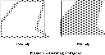 Figure 25–Drawing Polygons
If a polygon is open and being formed, FramePoly affects the outline of the polygon just as if the line-drawing routines themselves had been called. If a region is open and being formed, the outside outline of the polygon being framed is mathematically added to the region’s boundary.
PROCEDURE PaintPoly (poly: PolyHandle);
PaintPoly paints the specified polygon with the current grafPort’s pen pattern and pen mode. The polygon is filled with the pnPat, according to the pattern transfer mode specified by pnMode. The pen location is not changed by this procedure.
PROCEDURE ErasePoly (poly: PolyHandle);
ErasePoly paints the specified polygon with the current grafPort’s background pattern bkPat (in patCopy mode). The pnPat and pnMode are ignored; the pen location is not changed.
PROCEDURE InvertPoly (poly: PolyHandle);
InvertPoly inverts the pixels enclosed by the specified polygon: Every white pixel becomes black and every black pixel becomes white. The grafPort’s pnPat, pnMode, and bkPat are all ignored; the pen location is not changed.
PROCEDURE FillPoly (poly: PolyHandle; pat: Pattern);
FillPoly fills the specified polygon with the given pattern (in patCopy mode). The grafPort’s pnPat, pnMode, and bkPat are all ignored; the pen location is not changed.
_______________________________________________________________________________
»Calculations with Points
PROCEDURE AddPt (srcPt: Point; VAR dstPt: Point);
AddPt adds the coordinates of srcPt to the coordinates of dstPt, and returns the result in dstPt.
PROCEDURE SubPt (srcPt: Point; VAR dstPt: Point);
SubPt subtracts the coordinates of srcPt from the coordinates of dstPt, and returns the result in dstPt.
Note: To get the results of coordinate subtraction returned as a function
result, you can use the Toolbox Utility function DeltaPoint.
PROCEDURE SetPt (VAR pt: Point; h,v: INTEGER);
SetPt assigns the two given coordinates to the point pt.
FUNCTION EqualPt (pt1,pt2: Point) : BOOLEAN;
EqualPt compares the two given points and returns TRUE if they’re equal or FALSE if not.
PROCEDURE LocalToGlobal (VAR pt: Point);
LocalToGlobal converts the given point from the current grafPort’s local coordinate system into a global coordinate system with the origin (0,0) at the top left corner of the port’s bit image (such as the screen). This global point can then be compared to other global points, or be changed into the local coordinates of another grafPort.
Since a rectangle is defined by two points, you can convert a rectangle into global coordinates by performing two LocalToGlobal calls. You can also convert a rectangle, region, or polygon into global coordinates by calling OffsetRect, OffsetRgn, or OffsetPoly. For examples, see GlobalToLocal below.
PROCEDURE GlobalToLocal (VAR pt: Point);
GlobalToLocal takes a point expressed in global coordinates (with the top left corner of the bit image as coordinate (0,0)) and converts it into the local coordinates of the current grafPort. The global point can be obtained with the LocalToGlobal call (see above). For example, suppose a game draws a “ball” within a rectangle named ballRect, defined in the grafPort named gamePort (as illustrated in Figure 26). If you want to draw that ball in the grafPort named selectPort, you can calculate the ball’s selectPort coordinates like this:
SetPort(gamePort); {start in origin port}
selectBall := ballRect; {make a copy to be moved}
LocalToGlobal(selectBall.topLeft); {put both corners into }
LocalToGlobal(selectBall.botRight); { global coordinates}
SetPort(selectPort); {switch to destination port}
GlobalToLocal(selectBall.topLeft); {put both corners into }
GlobalToLocal(selectBall.botRight); { these local coordinates}
FillOval(selectBall,ballColor) {draw the ball}
Figure 25–Drawing Polygons
If a polygon is open and being formed, FramePoly affects the outline of the polygon just as if the line-drawing routines themselves had been called. If a region is open and being formed, the outside outline of the polygon being framed is mathematically added to the region’s boundary.
PROCEDURE PaintPoly (poly: PolyHandle);
PaintPoly paints the specified polygon with the current grafPort’s pen pattern and pen mode. The polygon is filled with the pnPat, according to the pattern transfer mode specified by pnMode. The pen location is not changed by this procedure.
PROCEDURE ErasePoly (poly: PolyHandle);
ErasePoly paints the specified polygon with the current grafPort’s background pattern bkPat (in patCopy mode). The pnPat and pnMode are ignored; the pen location is not changed.
PROCEDURE InvertPoly (poly: PolyHandle);
InvertPoly inverts the pixels enclosed by the specified polygon: Every white pixel becomes black and every black pixel becomes white. The grafPort’s pnPat, pnMode, and bkPat are all ignored; the pen location is not changed.
PROCEDURE FillPoly (poly: PolyHandle; pat: Pattern);
FillPoly fills the specified polygon with the given pattern (in patCopy mode). The grafPort’s pnPat, pnMode, and bkPat are all ignored; the pen location is not changed.
_______________________________________________________________________________
»Calculations with Points
PROCEDURE AddPt (srcPt: Point; VAR dstPt: Point);
AddPt adds the coordinates of srcPt to the coordinates of dstPt, and returns the result in dstPt.
PROCEDURE SubPt (srcPt: Point; VAR dstPt: Point);
SubPt subtracts the coordinates of srcPt from the coordinates of dstPt, and returns the result in dstPt.
Note: To get the results of coordinate subtraction returned as a function
result, you can use the Toolbox Utility function DeltaPoint.
PROCEDURE SetPt (VAR pt: Point; h,v: INTEGER);
SetPt assigns the two given coordinates to the point pt.
FUNCTION EqualPt (pt1,pt2: Point) : BOOLEAN;
EqualPt compares the two given points and returns TRUE if they’re equal or FALSE if not.
PROCEDURE LocalToGlobal (VAR pt: Point);
LocalToGlobal converts the given point from the current grafPort’s local coordinate system into a global coordinate system with the origin (0,0) at the top left corner of the port’s bit image (such as the screen). This global point can then be compared to other global points, or be changed into the local coordinates of another grafPort.
Since a rectangle is defined by two points, you can convert a rectangle into global coordinates by performing two LocalToGlobal calls. You can also convert a rectangle, region, or polygon into global coordinates by calling OffsetRect, OffsetRgn, or OffsetPoly. For examples, see GlobalToLocal below.
PROCEDURE GlobalToLocal (VAR pt: Point);
GlobalToLocal takes a point expressed in global coordinates (with the top left corner of the bit image as coordinate (0,0)) and converts it into the local coordinates of the current grafPort. The global point can be obtained with the LocalToGlobal call (see above). For example, suppose a game draws a “ball” within a rectangle named ballRect, defined in the grafPort named gamePort (as illustrated in Figure 26). If you want to draw that ball in the grafPort named selectPort, you can calculate the ball’s selectPort coordinates like this:
SetPort(gamePort); {start in origin port}
selectBall := ballRect; {make a copy to be moved}
LocalToGlobal(selectBall.topLeft); {put both corners into }
LocalToGlobal(selectBall.botRight); { global coordinates}
SetPort(selectPort); {switch to destination port}
GlobalToLocal(selectBall.topLeft); {put both corners into }
GlobalToLocal(selectBall.botRight); { these local coordinates}
FillOval(selectBall,ballColor) {draw the ball}
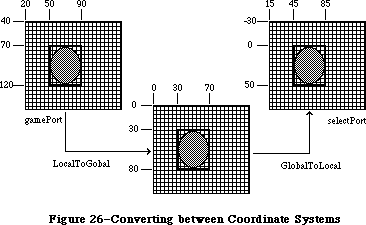 Figure 26–Converting between Coordinate Systems
You can see from Figure 26 that LocalToGlobal and GlobalToLocal simply offset the coordinates of the rectangle by the coordinates of the top left corner of the local grafPort’s portBits.bounds rectangle. You could also do this with OffsetRect. In fact, the way to convert regions and polygons from one coordinate system to another is with OffsetRgn or OffsetPoly rather than LocalToGlobal and GlobalToLocal. For example, if myRgn were a region enclosed by a rectangle having the same coordinates as ballRect in gamePort, you could convert the region to global coordinates with
OffsetRgn(myRgn,-20,-40)
and then convert it to the coordinates of the selectPort grafPort with
OffsetRgn(myRgn,15,-30)
_______________________________________________________________________________
»Miscellaneous Routines
FUNCTION Random : INTEGER;
This function returns a pseudo-random integer, uniformly distributed in the range –32767 through 32767. The value the sequence starts from depends on the global variable randSeed, which InitGraf initializes to 1. To start the sequence over again from where it began, reset randSeed to 1. To start a new sequence each time, you must reset randSeed to a random number.
Note: You can start a new sequence by storing the current date and time
in randSeed; see GetDateTime in the Operating System Utilities chapter.
Assembly-language note: From assembly language, it’s better to start a new
sequence by storing the value of the system global
variable RndSeed in randSeed.
FUNCTION GetPixel (h,v: INTEGER) : BOOLEAN;
GetPixel looks at the pixel associated with the given coordinate point and returns TRUE if it’s black or FALSE if it’s white. The selected pixel is immediately below and to the right of the point whose coordinates are given in h and v, in the local coordinates of the current grafPort. There’s no guarantee that the specified pixel actually belongs to the port, however; it may have been drawn by a port overlapping the current one. To see if the point indeed belongs to the current port, you could call PtInRgn(pt, thePort^.visRgn).
Note: To find out which window’s grafPort a point lies in, you call the
Window Manager function FindWindow, as described in the Window
Manager chapter.
PROCEDURE StuffHex (thingPtr: Ptr; s: Str255);
StuffHex stores bits (expressed as a string of hexadecimal digits) into any data structure. You can easily create a pattern in your program with StuffHex
(though more likely, you’ll store patterns in a resource file). For example,
StuffHex(@stripes,'0102040810204080')
places a striped pattern into the pattern variable named stripes.
Warning: There’s no range checking on the size of the destination variable.
It’s easy to overrun the variable and destroy something if you
don’t know what you’re doing.
PROCEDURE ScalePt (VAR pt: Point; srcRect,dstRect: Rect);
A width and height are passed in pt; the horizontal component of pt is the width, and its vertical component is the height. ScalePt scales these measurements as follows and returns the result in pt: It multiplies the given width by the ratio of dstRect’s width to srcRect’s width, and multiplies the given height by the ratio of dstRect’s height to srcRect’s height.
ScalePt can be used, for example, for scaling the pen dimensions. In Figure 27, where dstRect’s width is twice srcRect’s width and its height is three times srcRect’s height, the pen width is scaled from 3 to 6 and the pen height is scaled from 2 to 6.
Note: The minimum value ScalePt will return is (1,1).
Figure 26–Converting between Coordinate Systems
You can see from Figure 26 that LocalToGlobal and GlobalToLocal simply offset the coordinates of the rectangle by the coordinates of the top left corner of the local grafPort’s portBits.bounds rectangle. You could also do this with OffsetRect. In fact, the way to convert regions and polygons from one coordinate system to another is with OffsetRgn or OffsetPoly rather than LocalToGlobal and GlobalToLocal. For example, if myRgn were a region enclosed by a rectangle having the same coordinates as ballRect in gamePort, you could convert the region to global coordinates with
OffsetRgn(myRgn,-20,-40)
and then convert it to the coordinates of the selectPort grafPort with
OffsetRgn(myRgn,15,-30)
_______________________________________________________________________________
»Miscellaneous Routines
FUNCTION Random : INTEGER;
This function returns a pseudo-random integer, uniformly distributed in the range –32767 through 32767. The value the sequence starts from depends on the global variable randSeed, which InitGraf initializes to 1. To start the sequence over again from where it began, reset randSeed to 1. To start a new sequence each time, you must reset randSeed to a random number.
Note: You can start a new sequence by storing the current date and time
in randSeed; see GetDateTime in the Operating System Utilities chapter.
Assembly-language note: From assembly language, it’s better to start a new
sequence by storing the value of the system global
variable RndSeed in randSeed.
FUNCTION GetPixel (h,v: INTEGER) : BOOLEAN;
GetPixel looks at the pixel associated with the given coordinate point and returns TRUE if it’s black or FALSE if it’s white. The selected pixel is immediately below and to the right of the point whose coordinates are given in h and v, in the local coordinates of the current grafPort. There’s no guarantee that the specified pixel actually belongs to the port, however; it may have been drawn by a port overlapping the current one. To see if the point indeed belongs to the current port, you could call PtInRgn(pt, thePort^.visRgn).
Note: To find out which window’s grafPort a point lies in, you call the
Window Manager function FindWindow, as described in the Window
Manager chapter.
PROCEDURE StuffHex (thingPtr: Ptr; s: Str255);
StuffHex stores bits (expressed as a string of hexadecimal digits) into any data structure. You can easily create a pattern in your program with StuffHex
(though more likely, you’ll store patterns in a resource file). For example,
StuffHex(@stripes,'0102040810204080')
places a striped pattern into the pattern variable named stripes.
Warning: There’s no range checking on the size of the destination variable.
It’s easy to overrun the variable and destroy something if you
don’t know what you’re doing.
PROCEDURE ScalePt (VAR pt: Point; srcRect,dstRect: Rect);
A width and height are passed in pt; the horizontal component of pt is the width, and its vertical component is the height. ScalePt scales these measurements as follows and returns the result in pt: It multiplies the given width by the ratio of dstRect’s width to srcRect’s width, and multiplies the given height by the ratio of dstRect’s height to srcRect’s height.
ScalePt can be used, for example, for scaling the pen dimensions. In Figure 27, where dstRect’s width is twice srcRect’s width and its height is three times srcRect’s height, the pen width is scaled from 3 to 6 and the pen height is scaled from 2 to 6.
Note: The minimum value ScalePt will return is (1,1).
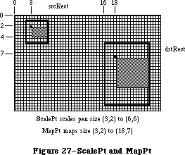 Figure 27–ScalePt and MapPt
PROCEDURE MapPt (VAR pt: Point; srcRect,dstRect: Rect);
Given a point within srcRect, MapPt maps it to a similarly located point within dstRect (that is, to where it would fall if it were part of a drawing being expanded or shrunk to fit dstRect). The result is returned in pt. A corner point of srcRect would be mapped to the corresponding corner point of dstRect, and the center of srcRect to the center of dstRect. In Figure 27, the point
(3,2) in srcRect is mapped to (18,7) in dstRect. SrcRect and dstRect may overlap, and pt need not actually be within srcRect.
Note: Remember, if you’re going to draw inside the destination rectangle,
you’ll probably also want to scale the pen size accordingly with ScalePt.
PROCEDURE MapRect (VAR r: Rect; srcRect,dstRect: Rect);
Given a rectangle within srcRect, MapRect maps it to a similarly located rectangle within dstRect by calling MapPt to map the top left and bottom right corners of the rectangle. The result is returned in r.
PROCEDURE MapRgn (rgn: RgnHandle; srcRect,dstRect: Rect);
Given a region within srcRect, MapRgn maps it to a similarly located region within dstRect by calling MapPt to map all the points in the region.
Note: MapRgn is useful for determining whether a region operation will
exceed available memory: By mapping a large region into a smaller
one and performing the operation (without actually drawing), you
can estimate how much memory will be required by the anticipated
operation.
PROCEDURE MapPoly (poly: PolyHandle; srcRect,dstRect: Rect);
Given a polygon within srcRect, MapPoly maps it to a similarly located polygon within dstRect by calling MapPt to map all the points that define the polygon.
Note: Like MapRgn, MapPoly is useful for determining whether a polygon
operation will succeed.
_______________________________________________________________________________
»Advanced Routine
The function GetMaskTable, accessible only from assembly language, returns in register A0 a pointer to a ROM table containing the following useful masks:
.WORD $0000,$8000,$C000,$E000 ;Table of 16 right masks
.WORD $F000,$F800,$FC00,$FE00
.WORD $FF00,$FF80,$FFC0,$FFE0
.WORD $FFF0,$FFF8,$FFFC,$FFFE
.WORD $FFFF,$7FFF,$3FFF,$1FFF ;Table of 16 left masks
.WORD $0FFF,$07FF,$03FF,$01FF
.WORD $00FF,$007F,$003F,$001F
.WORD $000F,$0007,$0003,$0001
.WORD $8000,$4000,$2000,$1000 ;Table of 16 bit masks
.WORD $0800,$0400,$0200,$0100
.WORD $0080,$0040,$0020,$0010
.WORD $0008,$0004,$0002,$0001
_______________________________________________________________________________
»CUSTOMIZING QUICKDRAW OPERATIONS
_______________________________________________________________________________
For each shape that QuickDraw knows how to draw, there are procedures that perform these basic graphic operations on the shape: frame, paint, erase, invert, and fill. Those procedures in turn call a low-level drawing routine for the shape. For example, the FrameOval, PaintOval, EraseOval, InvertOval, and FillOval procedures all call a low-level routine that draws the oval. For each type of object QuickDraw can draw, including text and lines, there’s a pointer to such a routine. By changing these pointers, you can install your own routines, and either completely override the standard ones or call them after your routines have modified parameters as necessary.
Other low-level routines that you can install in this way are:
• The procedure that does bit transfer and is called by CopyBits.
• The function that measures the width of text and is called by
CharWidth, StringWidth, and TextWidth.
• The procedure that processes picture comments and is called by
DrawPicture. The standard such procedure ignores picture comments.
• The procedure that saves drawing commands as the definition of a
picture, and the one that retrieves them. This enables the application
to draw on remote devices, print to the disk, get picture input from
the disk, and support large pictures.
The grafProcs field of a grafPort determines which low-level routines are called; if it contains NIL, the standard routines are called, so that all operations in that grafPort are done in the standard ways described in this chapter. You can set the grafProcs field to point to a record of pointers to routines. The data type of grafProcs is QDProcsPtr:
TYPE QDProcsPtr = ^QDProcs;
QDProcs = RECORD
textProc: Ptr; {text drawing}
lineProc: Ptr; {line drawing}
rectProc: Ptr; {rectangle drawing}
rRectProc: Ptr; {roundRect drawing}
ovalProc: Ptr; {oval drawing}
arcProc: Ptr; {arc/wedge drawing}
polyProc: Ptr; {polygon drawing}
rgnProc: Ptr; {region drawing}
bitsProc: Ptr; {bit transfer}
commentProc: Ptr; {picture comment processing}
txMeasProc: Ptr; {text width measurement}
getPicProc: Ptr; {picture retrieval}
putPicProc: Ptr {picture saving}
END;
To assist you in setting up a QDProcs record, QuickDraw provides the following procedure:
PROCEDURE SetStdProcs (VAR procs: QDProcs);
This procedure sets all the fields of the given QDProcs record to point to the standard low-level routines. You can then change the ones you wish to point to your own routines. For example, if your procedure that processes picture comments is named MyComments, you’ll store @MyComments in the commentProc field of the QDProcs record.
You can either write your own routines to completely replace the standard ones, or do preprocessing and then call the standard routines. The routines you install must of course have the same calling sequences as the standard routines, which are described below.
Note: These low-level routines should be called only from your
customized routines.
The standard drawing routines tell which graphic operation to perform from a parameter of type GrafVerb:
TYPE GrafVerb = (frame,paint,erase,invert,fill);
When the grafVerb is fill, the pattern to use during filling is passed in the fillPat field of the grafPort.
PROCEDURE StdText (byteCount: INTEGER; textBuf: Ptr; numer,denom: Point);
StdText is the standard low-level routine for drawing text. It draws text from the arbitrary structure in memory specified by textBuf, starting from the first byte and continuing for byteCount bytes. Numer and denom specify the scaling factor: numer.v over denom.v gives the vertical scaling, and numer.h over denom.h gives the horizontal scaling.
PROCEDURE StdLine (newPt: Point);
StdLine is the standard low-level routine for drawing a line. It draws a line from the current pen location to the location specified (in local coordinates) by newPt.
PROCEDURE StdRect (verb: GrafVerb; r: Rect);
StdRect is the standard low-level routine for drawing a rectangle. It draws the given rectangle according to the specified grafVerb.
PROCEDURE StdRRect (verb: GrafVerb; r: Rect; ovalwidth, ovalHeight: INTEGER)
StdRRect is the standard low-level routine for drawing a rounded-corner rectangle. It draws the given rounded-corner rectangle according to the specified grafVerb. OvalWidth and ovalHeight specify the diameters of curvature for the corners.
PROCEDURE StdOval (verb: GrafVerb; r: Rect);
StdOval is the standard low-level routine for drawing an oval. It draws an oval inside the given rectangle according to the specified grafVerb.
PROCEDURE StdArc (verb: GrafVerb; r: Rect; startAngle,arcAngle: INTEGER);
StdArc is the standard low-level routine for drawing an arc or a wedge. It draws an arc or wedge of the oval that fits inside the given rectangle, beginning at startAngle and extending to arcAngle. The grafVerb specifies the graphic operation; if it’s the frame operation, an arc is drawn; otherwise, a wedge is drawn.
PROCEDURE StdPoly (verb: GrafVerb; poly: PolyHandle);
StdPoly is the standard low-level routine for drawing a polygon. It draws the given polygon according to the specified grafVerb.
PROCEDURE StdRgn (verb: GrafVerb; rgn: RgnHandle);
StdRgn is the standard low-level routine for drawing a region. It draws the given region according to the specified grafVerb.
PROCEDURE StdBits (VAR srcBits: BitMap; VAR srcRect,dstRect: Rect;
mode: INTEGER; maskRgn: RgnHandle);
StdBits is the standard low-level routine for doing bit transfer. It transfers a bit image between the given bit map and thePort^.portBits, just as if CopyBits were called with the same parameters and with a destination bit map equal to thePort^.portBits.
PROCEDURE StdComment (kind,dataSize: INTEGER; dataHandle: Handle);
StdComment is the standard low-level routine for processing a picture comment. The kind parameter identifies the type of comment. DataHandle is a handle to additional data, and dataSize is the size of that data in bytes. If there’s no additional data for the comment, dataHandle will be NIL and dataSize will be 0. StdComment simply ignores the comment.
FUNCTION StdTxMeas (byteCount: INTEGER; textAddr: Ptr;
VAR numer, denom: Point; VAR info: FontInfo) : INTEGER;
StdTxMeas is the standard low-level routine for measuring text width. It returns the width of the text stored in the arbitrary structure in memory specified by textAddr, starting with the first byte and continuing for byteCount bytes. Numer and denom specify the scaling as in the StdText procedure; note that StdTxMeas may change them.
PROCEDURE StdGetPic (dataPtr: Ptr; byteCount: INTEGER);
StdGetPic is the standard low-level routine for retrieving information from the definition of a picture. It retrieves the next byteCount bytes from the definition of the currently open picture and stores them in the data structure pointed to by dataPtr.
PROCEDURE StdPutPic (dataPtr: Ptr; byteCount: INTEGER);
StdPutPic is the standard low-level routine for saving information as the definition of a picture. It saves as the definition of the currently open picture the drawing commands stored in the data structure pointed to by dataPtr, starting with the first byte and continuing for the next byteCount bytes.
_______________________________________________________________________________
»SUMMARY OF QUICKDRAW
_______________________________________________________________________________
Constants
CONST
{ Source transfer modes }
srcCopy = 0;
srcOr = 1;
srcXor = 2;
srcBic = 3;
notSrcCopy = 4;
notSrcOr = 5;
notSrcXor = 6;
notSrcBic = 7;
{ Pattern transfer modes }
patCopy = 8;
patOr = 9;
patXor = 10;
patBic = 11;
notPatCopy = 12;
notPatOr = 13;
notPatXor = 14;
notPatBic = 15;
{ Standard colors for ForeColor and BackColor }
blackColor = 33;
whiteColor = 30;
redColor = 209;
greenColor = 329;
blueColor = 389;
cyanColor = 269;
magentaColor = 149;
yellowColor = 89;
{ Standard picture comments }
picLParen = 0;
picRParen = 1;
_______________________________________________________________________________
Data Types
TYPE
StyleItem = (bold,italic,underline,outline,shadow,condense,extend);
Style = SET OF StyleItem;
VHSelect = (v,h);
Point = RECORD CASE INTEGER OF
0: (v: INTEGER; {vertical coordinate}
h: INTEGER); {horizontal coordinate}
1: (vh: ARRAY[VHSelect] OF INTEGER)
END;
Rect = RECORD CASE INTEGER OF
0: (top: INTEGER;
left: INTEGER;
bottom: INTEGER;
right: INTEGER);
1: (topLeft: Point;
botRight: Point)
END;
RgnHandle = ^RgnPtr;
RgnPtr = ^Region;
Region = RECORD
rgnSize: INTEGER; {size in bytes}
rgnBBox: Rect; {enclosing rectangle}
{more data if not rectangular}
END;
BitMap = RECORD
baseAddr: Ptr; {pointer to bit image}
rowBytes: INTEGER; {row width}
bounds: Rect {boundary rectangle}
END;
Pattern = PACKED ARRAY[0..7] OF 0..255;
Bits16 = ARRAY[0..15] OF INTEGER;
Cursor = RECORD
data: Bits16; {cursor image}
mask: Bits16; {cursor mask}
hotSpot: Point {point aligned with mouse}
END;
QDProcsPtr = ^QDProcs;
QDProcs = RECORD
textProc: Ptr; {text drawing}
lineProc: Ptr; {line drawing}
rectProc: Ptr; {rectangle drawing}
rRectProc: Ptr; {roundRect drawing}
ovalProc: Ptr; {oval drawing}
arcProc: Ptr; {arc/wedge drawing}
rgnProc: Ptr; {region drawing}
bitsProc: Ptr; {bit transfer}
commentProc: Ptr; {picture comment processing}
txMeasProc: Ptr; {text width measurement}
getPicProc: Ptr; {picture retrieval}
putPicProc: Ptr {picture saving}
END;
GrafPtr = ^GrafPort;
GrafPort = RECORD
device: INTEGER; {device-specific information}
portBits: BitMap; {grafPort's bit map}
portRect: Rect; {grafPort's rectangle}
visRgn: RgnHandle; {visible region}
clipRgn: RgnHandle; {clipping region}
bkPat: Pattern; {background pattern}
fillPat: Pattern; {fill pattern}
pnLoc: Point; {pen location}
pnSize: Point; {pen size}
pnMode: INTEGER; {pen's transfer mode}
pnPat: Pattern; {pen pattern}
pnVis: INTEGER; {pen visibility}
txFont: INTEGER; {font number for text}
txFace: Style; {text's character style}
txMode: INTEGER; {text's transfer mode}
txSize: INTEGER; {font size for text}
spExtra: Fixed; {extra space}
fgColor: LONGINT; {foreground color}
bkColor: LONGINT; {background color}
colrBit: INTEGER; {color bit}
patStretch: INTEGER; {used internally}
picSave: Handle; {picture being saved}
rgnSave: Handle; {region being saved}
polySave: Handle; {polygon being saved}
grafProcs: QDProcsPtr {low-level drawing routines}
END;
PicHandle = ^PicPtr;
PicPtr = ^Picture;
Picture = RECORD
picSize: INTEGER; {size in bytes}
picFrame: Rect; {picture frame}
{picture definition data}
END;
PolyHandle = ^PolyPtr;
PolyPtr = ^Polygon;
Polygon = RECORD
polySize: INTEGER; {size in bytes}
polyBBox: Rect; {enclosing rectangle}
polyPoints: ARRAY[0..0] OF Point
END;
PenState = RECORD
pnLoc: Point; {pen location}
pnSize: Point; {pen size}
pnMode: INTEGER; {pen's transfer mode}
pnPat: Pattern {pen pattern}
END;
FontInfo = RECORD
ascent: INTEGER; {ascent}
descent: INTEGER; {descent}
widMax: INTEGER; {maximum character width}
leading: INTEGER {leading}
END;
GrafVerb = (frame,paint,erase,invert,fill);
_______________________________________________________________________________
Variables
VAR
thePort: GrafPtr; {pointer to current grafPort}
white: Pattern; {all-white pattern}
black: Pattern; {all-black pattern}
gray: Pattern; {50% gray pattern}
ltGray: Pattern; {25% gray pattern}
dkGray: Pattern; {75% gray pattern}
arrow: Cursor; {standard arrow cursor}
screenBits: BitMap; {the entire screen}
randSeed: LONGINT; {determines where Random sequence begins}
_______________________________________________________________________________
Routines
GrafPort Routines
PROCEDURE InitGraf (globalPtr: Ptr);
PROCEDURE OpenPort (port: GrafPtr);
PROCEDURE InitPort (port: GrafPtr);
PROCEDURE ClosePort (port: GrafPtr);
PROCEDURE SetPort (port: GrafPtr);
PROCEDURE GetPort (VAR port:GrafPtr);
PROCEDURE GrafDevice (device: INTEGER);
PROCEDURE SetPortBits (bm: BitMap);
PROCEDURE PortSize (width,height: INTEGER);
PROCEDURE MovePortTo (leftGlobal,topGlobal: INTEGER);
PROCEDURE SetOrigin (h,v: INTEGER);
PROCEDURE SetClip (rgn: RgnHandle);
PROCEDURE GetClip (rgn: RgnHandle);
PROCEDURE ClipRect (r: Rect);
PROCEDURE BackPat (pat: Pattern);
Cursor Handling
PROCEDURE InitCursor;
PROCEDURE SetCursor (crsr: Cursor);
PROCEDURE HideCursor;
PROCEDURE ShowCursor;
PROCEDURE ObscureCursor;
Pen and Line Drawing
PROCEDURE HidePen;
PROCEDURE ShowPen;
PROCEDURE GetPen (VAR pt: Point);
PROCEDURE GetPenState (VAR pnState: PenState);
PROCEDURE SetPenState (pnState: PenState);
PROCEDURE PenSize (width,height: INTEGER);
PROCEDURE PenMode (mode: INTEGER);
PROCEDURE PenPat (pat: Pattern);
PROCEDURE PenNormal;
PROCEDURE MoveTo (h,v: INTEGER);
PROCEDURE Move (dh,dv: INTEGER);
PROCEDURE LineTo (h,v: INTEGER);
PROCEDURE Line (dh,dv: INTEGER);
Text Drawing
PROCEDURE TextFont (font: INTEGER);
PROCEDURE TextFace (face: Style);
PROCEDURE TextMode (mode: INTEGER);
PROCEDURE TextSize (size: INTEGER);
PROCEDURE SpaceExtra (extra: Fixed);
PROCEDURE DrawChar (ch: CHAR);
PROCEDURE DrawString (s: Str255);
PROCEDURE DrawText (textBuf: Ptr; firstByte,byteCount: INTEGER);
FUNCTION CharWidth (ch: CHAR) : INTEGER;
FUNCTION StringWidth (s: Str255) : INTEGER;
FUNCTION TextWidth (textBuf: Ptr;
firstByte,byteCount: INTEGER) : INTEGER;
PROCEDURE MeasureText (count: INTEGER; textAddr,charLocs: Ptr);
PROCEDURE GetFontInfo (VAR info: FontInfo);
Drawing in Color
PROCEDURE ForeColor (color: LONGINT);
PROCEDURE BackColor (color: LONGINT);
PROCEDURE ColorBit (whichBit: INTEGER);
Calculations with Rectangles
PROCEDURE SetRect (VAR r: Rect; left,top,right,bottom: INTEGER);
PROCEDURE OffsetRect (VAR r: Rect; dh,dv: INTEGER);
PROCEDURE InsetRect (VAR r: Rect; dh,dv: INTEGER);
FUNCTION SectRect (src1,src2: Rect; VAR dstRect: Rect) : BOOLEAN;
PROCEDURE UnionRect (src1,src2: Rect; VAR dstRect: Rect);
FUNCTION PtInRect (pt: Point; r: Rect) : BOOLEAN;
PROCEDURE Pt2Rect (pt1,pt2: Point; VAR dstRect: Rect);
PROCEDURE PtToAngle (r: Rect; pt: Point; VAR angle: INTEGER);
FUNCTION EqualRect (rect1,rect2: Rect) : BOOLEAN;
FUNCTION EmptyRect (r: Rect) : BOOLEAN;
Graphic Operations on Rectangles
PROCEDURE FrameRect (r: Rect);
PROCEDURE PaintRect (r: Rect);
PROCEDURE EraseRect (r: Rect);
PROCEDURE InvertRect (r: Rect);
PROCEDURE FillRect (r: Rect; pat: Pattern);
Graphic Operations on Ovals
PROCEDURE FrameOval (r: Rect);
PROCEDURE PaintOval (r: Rect);
PROCEDURE EraseOval (r: Rect);
PROCEDURE InvertOval (r: Rect);
PROCEDURE FillOval (r: Rect; pat: Pattern);
Graphic Operations on Rounded-Corner Rectangles
PROCEDURE FrameRoundRect (r: Rect; ovalWidth,ovalHeight: INTEGER);
PROCEDURE PaintRoundRect (r: Rect; ovalWidth,ovalHeight: INTEGER);
PROCEDURE EraseRoundRect (r: Rect; ovalWidth,ovalHeight: INTEGER);
PROCEDURE InvertRoundRect (r: Rect; ovalWidth,ovalHeight: INTEGER);
PROCEDURE FillRoundRect (r: Rect; ovalWidth,ovalHeight: INTEGER;
pat: Pattern);
Graphic Operations on Arcs and Wedges
PROCEDURE FrameArc (r: Rect; startAngle,arcAngle: INTEGER);
PROCEDURE PaintArc (r: Rect; startAngle,arcAngle: INTEGER);
PROCEDURE EraseArc (r: Rect; startAngle,arcAngle: INTEGER);
PROCEDURE InvertArc (r: Rect; startAngle,arcAngle: INTEGER);
PROCEDURE FillArc (r: Rect; startAngle,arcAngle: INTEGER; pat: Pattern);
Calculations with Regions
FUNCTION NewRgn : RgnHandle;
PROCEDURE OpenRgn;
PROCEDURE CloseRgn (dstRgn: RgnHandle);
PROCEDURE DisposeRgn (rgn: RgnHandle);
PROCEDURE CopyRgn (srcRgn,dstRgn: RgnHandle);
PROCEDURE SetEmptyRgn (rgn: RgnHandle);
PROCEDURE SetRectRgn (rgn: RgnHandle; left,top,right,bottom: INTEGER);
PROCEDURE RectRgn (rgn: RgnHandle; r: Rect);
PROCEDURE OffsetRgn (rgn: RgnHandle; dh,dv: INTEGER);
PROCEDURE InsetRgn (rgn: RgnHandle; dh,dv: INTEGER);
PROCEDURE SectRgn (srcRgnA,srcRgnB,dstRgn: RgnHandle);
PROCEDURE UnionRgn (srcRgnA,srcRgnB,dstRgn: RgnHandle);
PROCEDURE DiffRgn (srcRgnA,srcRgnB,dstRgn: RgnHandle);
PROCEDURE XorRgn (srcRgnA,srcRgnB,dstRgn: RgnHandle);
FUNCTION PtInRgn (pt: Point; rgn: RgnHandle) : BOOLEAN;
FUNCTION RectInRgn (r: Rect; rgn: RgnHandle) : BOOLEAN;
FUNCTION EqualRgn (rgnA,rgnB: RgnHandle) : BOOLEAN;
FUNCTION EmptyRgn (rgn: RgnHandle) : BOOLEAN;
Graphic Operations on Regions
PROCEDURE FrameRgn (rgn: RgnHandle);
PROCEDURE PaintRgn (rgn: RgnHandle);
PROCEDURE EraseRgn (rgn: RgnHandle);
PROCEDURE InvertRgn (rgn: RgnHandle);
PROCEDURE FillRgn (rgn: RgnHandle; pat: Pattern);
Bit Map Operations
PROCEDURE ScrollRect (r: Rect; dh,dv: INTEGER; updateRgn: RgnHandle);
PROCEDURE CopyBits (srcBits,dstBits: BitMap; srcRect,dstRect: Rect;
mode: INTEGER; maskRgn: RgnHandle);
PROCEDURE SeedFill (srcPtr,dstPtr: Ptr;
srcRow,dstRow,height,words, seedH,seedV: INTEGER);
PROCEDURE CalcMask (srcPtr,dstPtr: Ptr;
srcRow,dstRow,height,words: INTEGER);
PROCEDURE CopyMask (srcBits,maskBits,dstBits: BitMap;
srcRect, maskRect,dstRect: ect);
Pictures
FUNCTION OpenPicture (picFrame: Rect) : PicHandle;
PROCEDURE PicComment (kind,dataSize: INTEGER; dataHandle: Handle);
PROCEDURE ClosePicture;
PROCEDURE DrawPicture (myPicture: PicHandle; dstRect: Rect);
PROCEDURE KillPicture (myPicture: PicHandle);
Calculations with Polygons
FUNCTION OpenPoly : PolyHandle;
PROCEDURE ClosePoly;
PROCEDURE KillPoly (poly: PolyHandle);
PROCEDURE OffsetPoly (poly: PolyHandle; dh,dv: INTEGER);
Graphic Operations on Polygons
PROCEDURE FramePoly (poly: PolyHandle);
PROCEDURE PaintPoly (poly: PolyHandle);
PROCEDURE ErasePoly (poly: PolyHandle);
PROCEDURE InvertPoly (poly: PolyHandle);
PROCEDURE FillPoly (poly: PolyHandle; pat: Pattern);
Calculations with Points
PROCEDURE AddPt (srcPt: Point; VAR dstPt: Point);
PROCEDURE SubPt (srcPt: Point; VAR dstPt: Point);
PROCEDURE SetPt (VAR pt: Point; h,v: INTEGER);
FUNCTION EqualPt (pt1,pt2: Point) : BOOLEAN;
PROCEDURE LocalToGlobal (VAR pt: Point);
PROCEDURE GlobalToLocal (VAR pt: Point);
Miscellaneous Routines
FUNCTION Random : INTEGER;
FUNCTION GetPixel (h,v: INTEGER) : BOOLEAN;
PROCEDURE StuffHex (thingPtr: Ptr; s: Str255);
PROCEDURE ScalePt (VAR pt: Point; srcRect,dstRect: Rect);
PROCEDURE MapPt (VAR pt: Point; srcRect,dstRect: Rect);
PROCEDURE MapRect (VAR r: Rect; srcRect,dstRect: Rect);
PROCEDURE MapRgn (rgn: RgnHandle; srcRect,dstRect: Rect);
PROCEDURE MapPoly (poly: PolyHandle; srcRect,dstRect: Rect);
Customizing QuickDraw Operations
PROCEDURE SetStdProcs (VAR procs: QDProcs);
PROCEDURE StdText (byteCount: INTEGER; textBuf: Ptr;
numer,denom: Point);
PROCEDURE StdLine (newPt: Point);
PROCEDURE StdRect (verb: GrafVerb; r: Rect);
PROCEDURE StdRRect (verb: GrafVerb; r: Rect;
ovalwidth,ovalHeight: INTEGER);
PROCEDURE StdOval (verb: GrafVerb; r: Rect);
PROCEDURE StdArc (verb: GrafVerb; r: Rect;
startAngle,arcAngle: INTEGER);
PROCEDURE StdPoly (verb: GrafVerb; poly: PolyHandle);
PROCEDURE StdRgn (verb: GrafVerb; rgn: RgnHandle);
PROCEDURE StdBits (VAR srcBits: BitMap; VAR srcRect,dstRect: Rect;
mode: INTEGER; maskRgn: RgnHandle);
PROCEDURE StdComment (kind,dataSize: INTEGER; dataHandle: Handle);
FUNCTION StdTxMeas (byteCount: INTEGER; textAddr: Ptr;
VAR numer, denom: Point;
VAR info: FontInfo) : INTEGER;
PROCEDURE StdGetPic (dataPtr: Ptr; byteCount: INTEGER);
PROCEDURE StdPutPic (dataPtr: Ptr; byteCount: INTEGER);
_______________________________________________________________________________
Assembly-Language Information
Constants
; Size in bytes of QuickDraw global variables
grafSize .EQU 206
; Source transfer modes
srcCopy .EQU 0
srcOr .EQU 1
srcXor .EQU 2
srcBic .EQU 3
notSrcCopy .EQU 4
notSrcOr .EQU 5
notSrcXor .EQU 6
notSrcBic .EQU 7
; Pattern transfer modes
patCopy .EQU 8
patOr .EQU 9
patXor .EQU 10
patBic .EQU 11
notPatCopy .EQU 12
notPatOr .EQU 13
notPatXor .EQU 14
notPatBic .EQU 15
; Standard colors for ForeColor and BackColor
blackColor .EQU 33
whiteColor .EQU 30
redColor .EQU 205
greenColor .EQU 341
blueColor .EQU 409
cyanColor .EQU 273
magentaColor .EQU 137
yellowColor .EQU 69
; Standard picture comments
picLParen .EQU 0
picRParen .EQU 1
; Character style
boldBit .EQU 0
italicBit .EQU 1
ulineBit .EQU 2
outlineBit .EQU 3
shadowBit .EQU 4
condenseBit .EQU 5
extendBit .EQU 6
; Graphic operations
frame .EQU 0
paint .EQU 1
erase .EQU 2
invert .EQU 3
fill .EQU 4
Point Data Structure
v Vertical coordinate (word)
h Horizontal coordinate (word)
Rectangle Data Structure
top Vertical coordinate of top left corner (word)
left Horizontal coordinate of top left corner (word)
bottom Vertical coordinate of bottom right corner (word)
right Horizontal coordinate of bottom right corner (word)
topLeft Top left corner (point; long)
botRight Bottom right corner (point; long)
Region Data Structure
rgnSize Size in bytes (word)
rgnBBox Enclosing rectangle (8 bytes)
rgnData More data if not rectangular
Bit Map Data Structure
baseAddr Pointer to bit image
rowBytes Row width (word)
bounds Boundary rectangle (8 bytes)
bitMapRec Size in bytes of bit map data structure
Cursor Data Structure
data Cursor image (32 bytes)
mask Cursor mask (32 bytes)
hotSpot Point aligned with mouse (long)
cursRec Size in bytes of cursor data structure
Structure of QDProcs Record
textProc Address of text-drawing routine
lineProc Address of line-drawing routine
rectProc Address of rectangle-drawing routine
rRectProc Address of roundRect-drawing routine
ovalProc Address of oval-drawing routine
arcProc Address of arc/wedge-drawing routine
polyProc Address of polygon-drawing routine
rgnProc Address of region-drawing routine
bitsProc Address of bit-transfer routine
commentProc Address of routine for processing picture comments
txMeasProc Address of routine for measuring text width
getPicProc Address of picture-retrieval routine
putPicProc Address of picture-saving routine
qdProcsRec Size in bytes of QDProcs record
GrafPort Data Structure
device Font-specific information (word)
portBits GrafPort's bit map (bitMapRec bytes)
portBounds Boundary rectangle of grafPort's bit map (8 bytes)
portRect GrafPort's rectangle (8 bytes)
visRgn Handle to visible region
clipRgn Handle to clipping region
bkPat Background pattern (8 bytes)
fillPat Fill pattern (8 bytes)
pnLoc Pen location (point; long)
pnSize Pen size (point; long)
pnMode Pen's transfer mode (word)
pnPat Pen pattern (8 bytes)
pnVis Pen visibility (word)
txFont Font number for text (word)
txFace Text's character style (word)
txMode Text's transfer mode (word)
txSize Font size for text (word)
spExtra Extra space (long)
fgColor Foreground color (long)
bkColor Background color (long)
colrBit Color bit (word)
picSave Picture being saved
rgnSave Region being saved
polySave Polygon being saved
grafProcs Pointer to QDProcs record
Picture Data Structure
picSize Size in bytes (word)
picFrame Picture frame (rectangle; 8 bytes)
picData Picture definition data
Polygon Data Structure
polySize Size in bytes (word)
polyBBox Enclosing rectangle (8 bytes)
polyPoints Polygon points
Pen State Data Structure
psLoc Pen location (point; long)
psSize Pen size (point; long)
psMode Pen's transfer mode (word)
psPat Pen pattern (8 bytes)
psRec Size in bytes of pen state data structure
Font Information Data Structure
ascent Ascent (word)
descent Descent (word)
widMax Maximum character width (word)
leading Leading (word)
Special Macro Names
Pascal name Macro name
SetPortBits _SetPBits
InvertRect _InverRect
InvertRoundRect _InverRoundRect
DisposeRgn _DisposRgn
SetRectRgn _SetRecRgn
OffsetRgn _OfSetRgn
InvertRgn _InverRgn
ClosePoly _ClosePgon
Variables
RndSeed Random number seed (long)
Routine
Trap macro On entry On exit
_GetMaskTable A0: ptr to mask table in ROM
Further Reference:
_______________________________________________________________________________
Font Manager
Color QuickDraw
Technical Note #21, QuickDraw’s Internal Picture Definition
Technical Note #26, Character vs. String Operations in QuickDraw
Technical Note #41, Drawing Into an Offscreen Bitmap
Technical Note #55, Drawing Icons
Technical Note #59, Pictures and Clip Regions
Technical Note #60, Drawing Characters into a Narrow GrafPort
Technical Note #72, Optimizing for the LaserWriter — Techniques
Technical Note #73, Color Printing
Technical Note #86, MacPaint Document Format
Technical Note #91, Optimizing for the LaserWriter—Picture Comments
Technical Note #92, The Appearance of Text
Technical Note #120, Drawing Into an Off-Screen Pixel Map
Technical Note #154, Displaying Large PICT Files
Technical Note #155, Handles and Pointers—Identity Crisis
Technical Note #163, Adding Color With CopyBits
Technical Note #171, _PackBits Data Format
Technical Note #181, Every Picture [Comment] Tells Its Story, Don’t It?
Technical Note #183, Position-Independent PostScript
Technical Note #193, So Many Bitmaps, So Little Time
Technical Note #194, WMgrPortability
Technical Note #198, Font/DA Mover, Styled Fonts, and 'NFNT's
Technical Note #223, Assembly Language Use of _InitGraf with MPW
Technical Note #244, A Leading Cause of Color Cursor Cursing
Technical Note #252, Plotting Small Icons
Technical Note #259, Old Style Colors
32-Bit QuickDraw Documentation
Figure 27–ScalePt and MapPt
PROCEDURE MapPt (VAR pt: Point; srcRect,dstRect: Rect);
Given a point within srcRect, MapPt maps it to a similarly located point within dstRect (that is, to where it would fall if it were part of a drawing being expanded or shrunk to fit dstRect). The result is returned in pt. A corner point of srcRect would be mapped to the corresponding corner point of dstRect, and the center of srcRect to the center of dstRect. In Figure 27, the point
(3,2) in srcRect is mapped to (18,7) in dstRect. SrcRect and dstRect may overlap, and pt need not actually be within srcRect.
Note: Remember, if you’re going to draw inside the destination rectangle,
you’ll probably also want to scale the pen size accordingly with ScalePt.
PROCEDURE MapRect (VAR r: Rect; srcRect,dstRect: Rect);
Given a rectangle within srcRect, MapRect maps it to a similarly located rectangle within dstRect by calling MapPt to map the top left and bottom right corners of the rectangle. The result is returned in r.
PROCEDURE MapRgn (rgn: RgnHandle; srcRect,dstRect: Rect);
Given a region within srcRect, MapRgn maps it to a similarly located region within dstRect by calling MapPt to map all the points in the region.
Note: MapRgn is useful for determining whether a region operation will
exceed available memory: By mapping a large region into a smaller
one and performing the operation (without actually drawing), you
can estimate how much memory will be required by the anticipated
operation.
PROCEDURE MapPoly (poly: PolyHandle; srcRect,dstRect: Rect);
Given a polygon within srcRect, MapPoly maps it to a similarly located polygon within dstRect by calling MapPt to map all the points that define the polygon.
Note: Like MapRgn, MapPoly is useful for determining whether a polygon
operation will succeed.
_______________________________________________________________________________
»Advanced Routine
The function GetMaskTable, accessible only from assembly language, returns in register A0 a pointer to a ROM table containing the following useful masks:
.WORD $0000,$8000,$C000,$E000 ;Table of 16 right masks
.WORD $F000,$F800,$FC00,$FE00
.WORD $FF00,$FF80,$FFC0,$FFE0
.WORD $FFF0,$FFF8,$FFFC,$FFFE
.WORD $FFFF,$7FFF,$3FFF,$1FFF ;Table of 16 left masks
.WORD $0FFF,$07FF,$03FF,$01FF
.WORD $00FF,$007F,$003F,$001F
.WORD $000F,$0007,$0003,$0001
.WORD $8000,$4000,$2000,$1000 ;Table of 16 bit masks
.WORD $0800,$0400,$0200,$0100
.WORD $0080,$0040,$0020,$0010
.WORD $0008,$0004,$0002,$0001
_______________________________________________________________________________
»CUSTOMIZING QUICKDRAW OPERATIONS
_______________________________________________________________________________
For each shape that QuickDraw knows how to draw, there are procedures that perform these basic graphic operations on the shape: frame, paint, erase, invert, and fill. Those procedures in turn call a low-level drawing routine for the shape. For example, the FrameOval, PaintOval, EraseOval, InvertOval, and FillOval procedures all call a low-level routine that draws the oval. For each type of object QuickDraw can draw, including text and lines, there’s a pointer to such a routine. By changing these pointers, you can install your own routines, and either completely override the standard ones or call them after your routines have modified parameters as necessary.
Other low-level routines that you can install in this way are:
• The procedure that does bit transfer and is called by CopyBits.
• The function that measures the width of text and is called by
CharWidth, StringWidth, and TextWidth.
• The procedure that processes picture comments and is called by
DrawPicture. The standard such procedure ignores picture comments.
• The procedure that saves drawing commands as the definition of a
picture, and the one that retrieves them. This enables the application
to draw on remote devices, print to the disk, get picture input from
the disk, and support large pictures.
The grafProcs field of a grafPort determines which low-level routines are called; if it contains NIL, the standard routines are called, so that all operations in that grafPort are done in the standard ways described in this chapter. You can set the grafProcs field to point to a record of pointers to routines. The data type of grafProcs is QDProcsPtr:
TYPE QDProcsPtr = ^QDProcs;
QDProcs = RECORD
textProc: Ptr; {text drawing}
lineProc: Ptr; {line drawing}
rectProc: Ptr; {rectangle drawing}
rRectProc: Ptr; {roundRect drawing}
ovalProc: Ptr; {oval drawing}
arcProc: Ptr; {arc/wedge drawing}
polyProc: Ptr; {polygon drawing}
rgnProc: Ptr; {region drawing}
bitsProc: Ptr; {bit transfer}
commentProc: Ptr; {picture comment processing}
txMeasProc: Ptr; {text width measurement}
getPicProc: Ptr; {picture retrieval}
putPicProc: Ptr {picture saving}
END;
To assist you in setting up a QDProcs record, QuickDraw provides the following procedure:
PROCEDURE SetStdProcs (VAR procs: QDProcs);
This procedure sets all the fields of the given QDProcs record to point to the standard low-level routines. You can then change the ones you wish to point to your own routines. For example, if your procedure that processes picture comments is named MyComments, you’ll store @MyComments in the commentProc field of the QDProcs record.
You can either write your own routines to completely replace the standard ones, or do preprocessing and then call the standard routines. The routines you install must of course have the same calling sequences as the standard routines, which are described below.
Note: These low-level routines should be called only from your
customized routines.
The standard drawing routines tell which graphic operation to perform from a parameter of type GrafVerb:
TYPE GrafVerb = (frame,paint,erase,invert,fill);
When the grafVerb is fill, the pattern to use during filling is passed in the fillPat field of the grafPort.
PROCEDURE StdText (byteCount: INTEGER; textBuf: Ptr; numer,denom: Point);
StdText is the standard low-level routine for drawing text. It draws text from the arbitrary structure in memory specified by textBuf, starting from the first byte and continuing for byteCount bytes. Numer and denom specify the scaling factor: numer.v over denom.v gives the vertical scaling, and numer.h over denom.h gives the horizontal scaling.
PROCEDURE StdLine (newPt: Point);
StdLine is the standard low-level routine for drawing a line. It draws a line from the current pen location to the location specified (in local coordinates) by newPt.
PROCEDURE StdRect (verb: GrafVerb; r: Rect);
StdRect is the standard low-level routine for drawing a rectangle. It draws the given rectangle according to the specified grafVerb.
PROCEDURE StdRRect (verb: GrafVerb; r: Rect; ovalwidth, ovalHeight: INTEGER)
StdRRect is the standard low-level routine for drawing a rounded-corner rectangle. It draws the given rounded-corner rectangle according to the specified grafVerb. OvalWidth and ovalHeight specify the diameters of curvature for the corners.
PROCEDURE StdOval (verb: GrafVerb; r: Rect);
StdOval is the standard low-level routine for drawing an oval. It draws an oval inside the given rectangle according to the specified grafVerb.
PROCEDURE StdArc (verb: GrafVerb; r: Rect; startAngle,arcAngle: INTEGER);
StdArc is the standard low-level routine for drawing an arc or a wedge. It draws an arc or wedge of the oval that fits inside the given rectangle, beginning at startAngle and extending to arcAngle. The grafVerb specifies the graphic operation; if it’s the frame operation, an arc is drawn; otherwise, a wedge is drawn.
PROCEDURE StdPoly (verb: GrafVerb; poly: PolyHandle);
StdPoly is the standard low-level routine for drawing a polygon. It draws the given polygon according to the specified grafVerb.
PROCEDURE StdRgn (verb: GrafVerb; rgn: RgnHandle);
StdRgn is the standard low-level routine for drawing a region. It draws the given region according to the specified grafVerb.
PROCEDURE StdBits (VAR srcBits: BitMap; VAR srcRect,dstRect: Rect;
mode: INTEGER; maskRgn: RgnHandle);
StdBits is the standard low-level routine for doing bit transfer. It transfers a bit image between the given bit map and thePort^.portBits, just as if CopyBits were called with the same parameters and with a destination bit map equal to thePort^.portBits.
PROCEDURE StdComment (kind,dataSize: INTEGER; dataHandle: Handle);
StdComment is the standard low-level routine for processing a picture comment. The kind parameter identifies the type of comment. DataHandle is a handle to additional data, and dataSize is the size of that data in bytes. If there’s no additional data for the comment, dataHandle will be NIL and dataSize will be 0. StdComment simply ignores the comment.
FUNCTION StdTxMeas (byteCount: INTEGER; textAddr: Ptr;
VAR numer, denom: Point; VAR info: FontInfo) : INTEGER;
StdTxMeas is the standard low-level routine for measuring text width. It returns the width of the text stored in the arbitrary structure in memory specified by textAddr, starting with the first byte and continuing for byteCount bytes. Numer and denom specify the scaling as in the StdText procedure; note that StdTxMeas may change them.
PROCEDURE StdGetPic (dataPtr: Ptr; byteCount: INTEGER);
StdGetPic is the standard low-level routine for retrieving information from the definition of a picture. It retrieves the next byteCount bytes from the definition of the currently open picture and stores them in the data structure pointed to by dataPtr.
PROCEDURE StdPutPic (dataPtr: Ptr; byteCount: INTEGER);
StdPutPic is the standard low-level routine for saving information as the definition of a picture. It saves as the definition of the currently open picture the drawing commands stored in the data structure pointed to by dataPtr, starting with the first byte and continuing for the next byteCount bytes.
_______________________________________________________________________________
»SUMMARY OF QUICKDRAW
_______________________________________________________________________________
Constants
CONST
{ Source transfer modes }
srcCopy = 0;
srcOr = 1;
srcXor = 2;
srcBic = 3;
notSrcCopy = 4;
notSrcOr = 5;
notSrcXor = 6;
notSrcBic = 7;
{ Pattern transfer modes }
patCopy = 8;
patOr = 9;
patXor = 10;
patBic = 11;
notPatCopy = 12;
notPatOr = 13;
notPatXor = 14;
notPatBic = 15;
{ Standard colors for ForeColor and BackColor }
blackColor = 33;
whiteColor = 30;
redColor = 209;
greenColor = 329;
blueColor = 389;
cyanColor = 269;
magentaColor = 149;
yellowColor = 89;
{ Standard picture comments }
picLParen = 0;
picRParen = 1;
_______________________________________________________________________________
Data Types
TYPE
StyleItem = (bold,italic,underline,outline,shadow,condense,extend);
Style = SET OF StyleItem;
VHSelect = (v,h);
Point = RECORD CASE INTEGER OF
0: (v: INTEGER; {vertical coordinate}
h: INTEGER); {horizontal coordinate}
1: (vh: ARRAY[VHSelect] OF INTEGER)
END;
Rect = RECORD CASE INTEGER OF
0: (top: INTEGER;
left: INTEGER;
bottom: INTEGER;
right: INTEGER);
1: (topLeft: Point;
botRight: Point)
END;
RgnHandle = ^RgnPtr;
RgnPtr = ^Region;
Region = RECORD
rgnSize: INTEGER; {size in bytes}
rgnBBox: Rect; {enclosing rectangle}
{more data if not rectangular}
END;
BitMap = RECORD
baseAddr: Ptr; {pointer to bit image}
rowBytes: INTEGER; {row width}
bounds: Rect {boundary rectangle}
END;
Pattern = PACKED ARRAY[0..7] OF 0..255;
Bits16 = ARRAY[0..15] OF INTEGER;
Cursor = RECORD
data: Bits16; {cursor image}
mask: Bits16; {cursor mask}
hotSpot: Point {point aligned with mouse}
END;
QDProcsPtr = ^QDProcs;
QDProcs = RECORD
textProc: Ptr; {text drawing}
lineProc: Ptr; {line drawing}
rectProc: Ptr; {rectangle drawing}
rRectProc: Ptr; {roundRect drawing}
ovalProc: Ptr; {oval drawing}
arcProc: Ptr; {arc/wedge drawing}
rgnProc: Ptr; {region drawing}
bitsProc: Ptr; {bit transfer}
commentProc: Ptr; {picture comment processing}
txMeasProc: Ptr; {text width measurement}
getPicProc: Ptr; {picture retrieval}
putPicProc: Ptr {picture saving}
END;
GrafPtr = ^GrafPort;
GrafPort = RECORD
device: INTEGER; {device-specific information}
portBits: BitMap; {grafPort's bit map}
portRect: Rect; {grafPort's rectangle}
visRgn: RgnHandle; {visible region}
clipRgn: RgnHandle; {clipping region}
bkPat: Pattern; {background pattern}
fillPat: Pattern; {fill pattern}
pnLoc: Point; {pen location}
pnSize: Point; {pen size}
pnMode: INTEGER; {pen's transfer mode}
pnPat: Pattern; {pen pattern}
pnVis: INTEGER; {pen visibility}
txFont: INTEGER; {font number for text}
txFace: Style; {text's character style}
txMode: INTEGER; {text's transfer mode}
txSize: INTEGER; {font size for text}
spExtra: Fixed; {extra space}
fgColor: LONGINT; {foreground color}
bkColor: LONGINT; {background color}
colrBit: INTEGER; {color bit}
patStretch: INTEGER; {used internally}
picSave: Handle; {picture being saved}
rgnSave: Handle; {region being saved}
polySave: Handle; {polygon being saved}
grafProcs: QDProcsPtr {low-level drawing routines}
END;
PicHandle = ^PicPtr;
PicPtr = ^Picture;
Picture = RECORD
picSize: INTEGER; {size in bytes}
picFrame: Rect; {picture frame}
{picture definition data}
END;
PolyHandle = ^PolyPtr;
PolyPtr = ^Polygon;
Polygon = RECORD
polySize: INTEGER; {size in bytes}
polyBBox: Rect; {enclosing rectangle}
polyPoints: ARRAY[0..0] OF Point
END;
PenState = RECORD
pnLoc: Point; {pen location}
pnSize: Point; {pen size}
pnMode: INTEGER; {pen's transfer mode}
pnPat: Pattern {pen pattern}
END;
FontInfo = RECORD
ascent: INTEGER; {ascent}
descent: INTEGER; {descent}
widMax: INTEGER; {maximum character width}
leading: INTEGER {leading}
END;
GrafVerb = (frame,paint,erase,invert,fill);
_______________________________________________________________________________
Variables
VAR
thePort: GrafPtr; {pointer to current grafPort}
white: Pattern; {all-white pattern}
black: Pattern; {all-black pattern}
gray: Pattern; {50% gray pattern}
ltGray: Pattern; {25% gray pattern}
dkGray: Pattern; {75% gray pattern}
arrow: Cursor; {standard arrow cursor}
screenBits: BitMap; {the entire screen}
randSeed: LONGINT; {determines where Random sequence begins}
_______________________________________________________________________________
Routines
GrafPort Routines
PROCEDURE InitGraf (globalPtr: Ptr);
PROCEDURE OpenPort (port: GrafPtr);
PROCEDURE InitPort (port: GrafPtr);
PROCEDURE ClosePort (port: GrafPtr);
PROCEDURE SetPort (port: GrafPtr);
PROCEDURE GetPort (VAR port:GrafPtr);
PROCEDURE GrafDevice (device: INTEGER);
PROCEDURE SetPortBits (bm: BitMap);
PROCEDURE PortSize (width,height: INTEGER);
PROCEDURE MovePortTo (leftGlobal,topGlobal: INTEGER);
PROCEDURE SetOrigin (h,v: INTEGER);
PROCEDURE SetClip (rgn: RgnHandle);
PROCEDURE GetClip (rgn: RgnHandle);
PROCEDURE ClipRect (r: Rect);
PROCEDURE BackPat (pat: Pattern);
Cursor Handling
PROCEDURE InitCursor;
PROCEDURE SetCursor (crsr: Cursor);
PROCEDURE HideCursor;
PROCEDURE ShowCursor;
PROCEDURE ObscureCursor;
Pen and Line Drawing
PROCEDURE HidePen;
PROCEDURE ShowPen;
PROCEDURE GetPen (VAR pt: Point);
PROCEDURE GetPenState (VAR pnState: PenState);
PROCEDURE SetPenState (pnState: PenState);
PROCEDURE PenSize (width,height: INTEGER);
PROCEDURE PenMode (mode: INTEGER);
PROCEDURE PenPat (pat: Pattern);
PROCEDURE PenNormal;
PROCEDURE MoveTo (h,v: INTEGER);
PROCEDURE Move (dh,dv: INTEGER);
PROCEDURE LineTo (h,v: INTEGER);
PROCEDURE Line (dh,dv: INTEGER);
Text Drawing
PROCEDURE TextFont (font: INTEGER);
PROCEDURE TextFace (face: Style);
PROCEDURE TextMode (mode: INTEGER);
PROCEDURE TextSize (size: INTEGER);
PROCEDURE SpaceExtra (extra: Fixed);
PROCEDURE DrawChar (ch: CHAR);
PROCEDURE DrawString (s: Str255);
PROCEDURE DrawText (textBuf: Ptr; firstByte,byteCount: INTEGER);
FUNCTION CharWidth (ch: CHAR) : INTEGER;
FUNCTION StringWidth (s: Str255) : INTEGER;
FUNCTION TextWidth (textBuf: Ptr;
firstByte,byteCount: INTEGER) : INTEGER;
PROCEDURE MeasureText (count: INTEGER; textAddr,charLocs: Ptr);
PROCEDURE GetFontInfo (VAR info: FontInfo);
Drawing in Color
PROCEDURE ForeColor (color: LONGINT);
PROCEDURE BackColor (color: LONGINT);
PROCEDURE ColorBit (whichBit: INTEGER);
Calculations with Rectangles
PROCEDURE SetRect (VAR r: Rect; left,top,right,bottom: INTEGER);
PROCEDURE OffsetRect (VAR r: Rect; dh,dv: INTEGER);
PROCEDURE InsetRect (VAR r: Rect; dh,dv: INTEGER);
FUNCTION SectRect (src1,src2: Rect; VAR dstRect: Rect) : BOOLEAN;
PROCEDURE UnionRect (src1,src2: Rect; VAR dstRect: Rect);
FUNCTION PtInRect (pt: Point; r: Rect) : BOOLEAN;
PROCEDURE Pt2Rect (pt1,pt2: Point; VAR dstRect: Rect);
PROCEDURE PtToAngle (r: Rect; pt: Point; VAR angle: INTEGER);
FUNCTION EqualRect (rect1,rect2: Rect) : BOOLEAN;
FUNCTION EmptyRect (r: Rect) : BOOLEAN;
Graphic Operations on Rectangles
PROCEDURE FrameRect (r: Rect);
PROCEDURE PaintRect (r: Rect);
PROCEDURE EraseRect (r: Rect);
PROCEDURE InvertRect (r: Rect);
PROCEDURE FillRect (r: Rect; pat: Pattern);
Graphic Operations on Ovals
PROCEDURE FrameOval (r: Rect);
PROCEDURE PaintOval (r: Rect);
PROCEDURE EraseOval (r: Rect);
PROCEDURE InvertOval (r: Rect);
PROCEDURE FillOval (r: Rect; pat: Pattern);
Graphic Operations on Rounded-Corner Rectangles
PROCEDURE FrameRoundRect (r: Rect; ovalWidth,ovalHeight: INTEGER);
PROCEDURE PaintRoundRect (r: Rect; ovalWidth,ovalHeight: INTEGER);
PROCEDURE EraseRoundRect (r: Rect; ovalWidth,ovalHeight: INTEGER);
PROCEDURE InvertRoundRect (r: Rect; ovalWidth,ovalHeight: INTEGER);
PROCEDURE FillRoundRect (r: Rect; ovalWidth,ovalHeight: INTEGER;
pat: Pattern);
Graphic Operations on Arcs and Wedges
PROCEDURE FrameArc (r: Rect; startAngle,arcAngle: INTEGER);
PROCEDURE PaintArc (r: Rect; startAngle,arcAngle: INTEGER);
PROCEDURE EraseArc (r: Rect; startAngle,arcAngle: INTEGER);
PROCEDURE InvertArc (r: Rect; startAngle,arcAngle: INTEGER);
PROCEDURE FillArc (r: Rect; startAngle,arcAngle: INTEGER; pat: Pattern);
Calculations with Regions
FUNCTION NewRgn : RgnHandle;
PROCEDURE OpenRgn;
PROCEDURE CloseRgn (dstRgn: RgnHandle);
PROCEDURE DisposeRgn (rgn: RgnHandle);
PROCEDURE CopyRgn (srcRgn,dstRgn: RgnHandle);
PROCEDURE SetEmptyRgn (rgn: RgnHandle);
PROCEDURE SetRectRgn (rgn: RgnHandle; left,top,right,bottom: INTEGER);
PROCEDURE RectRgn (rgn: RgnHandle; r: Rect);
PROCEDURE OffsetRgn (rgn: RgnHandle; dh,dv: INTEGER);
PROCEDURE InsetRgn (rgn: RgnHandle; dh,dv: INTEGER);
PROCEDURE SectRgn (srcRgnA,srcRgnB,dstRgn: RgnHandle);
PROCEDURE UnionRgn (srcRgnA,srcRgnB,dstRgn: RgnHandle);
PROCEDURE DiffRgn (srcRgnA,srcRgnB,dstRgn: RgnHandle);
PROCEDURE XorRgn (srcRgnA,srcRgnB,dstRgn: RgnHandle);
FUNCTION PtInRgn (pt: Point; rgn: RgnHandle) : BOOLEAN;
FUNCTION RectInRgn (r: Rect; rgn: RgnHandle) : BOOLEAN;
FUNCTION EqualRgn (rgnA,rgnB: RgnHandle) : BOOLEAN;
FUNCTION EmptyRgn (rgn: RgnHandle) : BOOLEAN;
Graphic Operations on Regions
PROCEDURE FrameRgn (rgn: RgnHandle);
PROCEDURE PaintRgn (rgn: RgnHandle);
PROCEDURE EraseRgn (rgn: RgnHandle);
PROCEDURE InvertRgn (rgn: RgnHandle);
PROCEDURE FillRgn (rgn: RgnHandle; pat: Pattern);
Bit Map Operations
PROCEDURE ScrollRect (r: Rect; dh,dv: INTEGER; updateRgn: RgnHandle);
PROCEDURE CopyBits (srcBits,dstBits: BitMap; srcRect,dstRect: Rect;
mode: INTEGER; maskRgn: RgnHandle);
PROCEDURE SeedFill (srcPtr,dstPtr: Ptr;
srcRow,dstRow,height,words, seedH,seedV: INTEGER);
PROCEDURE CalcMask (srcPtr,dstPtr: Ptr;
srcRow,dstRow,height,words: INTEGER);
PROCEDURE CopyMask (srcBits,maskBits,dstBits: BitMap;
srcRect, maskRect,dstRect: ect);
Pictures
FUNCTION OpenPicture (picFrame: Rect) : PicHandle;
PROCEDURE PicComment (kind,dataSize: INTEGER; dataHandle: Handle);
PROCEDURE ClosePicture;
PROCEDURE DrawPicture (myPicture: PicHandle; dstRect: Rect);
PROCEDURE KillPicture (myPicture: PicHandle);
Calculations with Polygons
FUNCTION OpenPoly : PolyHandle;
PROCEDURE ClosePoly;
PROCEDURE KillPoly (poly: PolyHandle);
PROCEDURE OffsetPoly (poly: PolyHandle; dh,dv: INTEGER);
Graphic Operations on Polygons
PROCEDURE FramePoly (poly: PolyHandle);
PROCEDURE PaintPoly (poly: PolyHandle);
PROCEDURE ErasePoly (poly: PolyHandle);
PROCEDURE InvertPoly (poly: PolyHandle);
PROCEDURE FillPoly (poly: PolyHandle; pat: Pattern);
Calculations with Points
PROCEDURE AddPt (srcPt: Point; VAR dstPt: Point);
PROCEDURE SubPt (srcPt: Point; VAR dstPt: Point);
PROCEDURE SetPt (VAR pt: Point; h,v: INTEGER);
FUNCTION EqualPt (pt1,pt2: Point) : BOOLEAN;
PROCEDURE LocalToGlobal (VAR pt: Point);
PROCEDURE GlobalToLocal (VAR pt: Point);
Miscellaneous Routines
FUNCTION Random : INTEGER;
FUNCTION GetPixel (h,v: INTEGER) : BOOLEAN;
PROCEDURE StuffHex (thingPtr: Ptr; s: Str255);
PROCEDURE ScalePt (VAR pt: Point; srcRect,dstRect: Rect);
PROCEDURE MapPt (VAR pt: Point; srcRect,dstRect: Rect);
PROCEDURE MapRect (VAR r: Rect; srcRect,dstRect: Rect);
PROCEDURE MapRgn (rgn: RgnHandle; srcRect,dstRect: Rect);
PROCEDURE MapPoly (poly: PolyHandle; srcRect,dstRect: Rect);
Customizing QuickDraw Operations
PROCEDURE SetStdProcs (VAR procs: QDProcs);
PROCEDURE StdText (byteCount: INTEGER; textBuf: Ptr;
numer,denom: Point);
PROCEDURE StdLine (newPt: Point);
PROCEDURE StdRect (verb: GrafVerb; r: Rect);
PROCEDURE StdRRect (verb: GrafVerb; r: Rect;
ovalwidth,ovalHeight: INTEGER);
PROCEDURE StdOval (verb: GrafVerb; r: Rect);
PROCEDURE StdArc (verb: GrafVerb; r: Rect;
startAngle,arcAngle: INTEGER);
PROCEDURE StdPoly (verb: GrafVerb; poly: PolyHandle);
PROCEDURE StdRgn (verb: GrafVerb; rgn: RgnHandle);
PROCEDURE StdBits (VAR srcBits: BitMap; VAR srcRect,dstRect: Rect;
mode: INTEGER; maskRgn: RgnHandle);
PROCEDURE StdComment (kind,dataSize: INTEGER; dataHandle: Handle);
FUNCTION StdTxMeas (byteCount: INTEGER; textAddr: Ptr;
VAR numer, denom: Point;
VAR info: FontInfo) : INTEGER;
PROCEDURE StdGetPic (dataPtr: Ptr; byteCount: INTEGER);
PROCEDURE StdPutPic (dataPtr: Ptr; byteCount: INTEGER);
_______________________________________________________________________________
Assembly-Language Information
Constants
; Size in bytes of QuickDraw global variables
grafSize .EQU 206
; Source transfer modes
srcCopy .EQU 0
srcOr .EQU 1
srcXor .EQU 2
srcBic .EQU 3
notSrcCopy .EQU 4
notSrcOr .EQU 5
notSrcXor .EQU 6
notSrcBic .EQU 7
; Pattern transfer modes
patCopy .EQU 8
patOr .EQU 9
patXor .EQU 10
patBic .EQU 11
notPatCopy .EQU 12
notPatOr .EQU 13
notPatXor .EQU 14
notPatBic .EQU 15
; Standard colors for ForeColor and BackColor
blackColor .EQU 33
whiteColor .EQU 30
redColor .EQU 205
greenColor .EQU 341
blueColor .EQU 409
cyanColor .EQU 273
magentaColor .EQU 137
yellowColor .EQU 69
; Standard picture comments
picLParen .EQU 0
picRParen .EQU 1
; Character style
boldBit .EQU 0
italicBit .EQU 1
ulineBit .EQU 2
outlineBit .EQU 3
shadowBit .EQU 4
condenseBit .EQU 5
extendBit .EQU 6
; Graphic operations
frame .EQU 0
paint .EQU 1
erase .EQU 2
invert .EQU 3
fill .EQU 4
Point Data Structure
v Vertical coordinate (word)
h Horizontal coordinate (word)
Rectangle Data Structure
top Vertical coordinate of top left corner (word)
left Horizontal coordinate of top left corner (word)
bottom Vertical coordinate of bottom right corner (word)
right Horizontal coordinate of bottom right corner (word)
topLeft Top left corner (point; long)
botRight Bottom right corner (point; long)
Region Data Structure
rgnSize Size in bytes (word)
rgnBBox Enclosing rectangle (8 bytes)
rgnData More data if not rectangular
Bit Map Data Structure
baseAddr Pointer to bit image
rowBytes Row width (word)
bounds Boundary rectangle (8 bytes)
bitMapRec Size in bytes of bit map data structure
Cursor Data Structure
data Cursor image (32 bytes)
mask Cursor mask (32 bytes)
hotSpot Point aligned with mouse (long)
cursRec Size in bytes of cursor data structure
Structure of QDProcs Record
textProc Address of text-drawing routine
lineProc Address of line-drawing routine
rectProc Address of rectangle-drawing routine
rRectProc Address of roundRect-drawing routine
ovalProc Address of oval-drawing routine
arcProc Address of arc/wedge-drawing routine
polyProc Address of polygon-drawing routine
rgnProc Address of region-drawing routine
bitsProc Address of bit-transfer routine
commentProc Address of routine for processing picture comments
txMeasProc Address of routine for measuring text width
getPicProc Address of picture-retrieval routine
putPicProc Address of picture-saving routine
qdProcsRec Size in bytes of QDProcs record
GrafPort Data Structure
device Font-specific information (word)
portBits GrafPort's bit map (bitMapRec bytes)
portBounds Boundary rectangle of grafPort's bit map (8 bytes)
portRect GrafPort's rectangle (8 bytes)
visRgn Handle to visible region
clipRgn Handle to clipping region
bkPat Background pattern (8 bytes)
fillPat Fill pattern (8 bytes)
pnLoc Pen location (point; long)
pnSize Pen size (point; long)
pnMode Pen's transfer mode (word)
pnPat Pen pattern (8 bytes)
pnVis Pen visibility (word)
txFont Font number for text (word)
txFace Text's character style (word)
txMode Text's transfer mode (word)
txSize Font size for text (word)
spExtra Extra space (long)
fgColor Foreground color (long)
bkColor Background color (long)
colrBit Color bit (word)
picSave Picture being saved
rgnSave Region being saved
polySave Polygon being saved
grafProcs Pointer to QDProcs record
Picture Data Structure
picSize Size in bytes (word)
picFrame Picture frame (rectangle; 8 bytes)
picData Picture definition data
Polygon Data Structure
polySize Size in bytes (word)
polyBBox Enclosing rectangle (8 bytes)
polyPoints Polygon points
Pen State Data Structure
psLoc Pen location (point; long)
psSize Pen size (point; long)
psMode Pen's transfer mode (word)
psPat Pen pattern (8 bytes)
psRec Size in bytes of pen state data structure
Font Information Data Structure
ascent Ascent (word)
descent Descent (word)
widMax Maximum character width (word)
leading Leading (word)
Special Macro Names
Pascal name Macro name
SetPortBits _SetPBits
InvertRect _InverRect
InvertRoundRect _InverRoundRect
DisposeRgn _DisposRgn
SetRectRgn _SetRecRgn
OffsetRgn _OfSetRgn
InvertRgn _InverRgn
ClosePoly _ClosePgon
Variables
RndSeed Random number seed (long)
Routine
Trap macro On entry On exit
_GetMaskTable A0: ptr to mask table in ROM
Further Reference:
_______________________________________________________________________________
Font Manager
Color QuickDraw
Technical Note #21, QuickDraw’s Internal Picture Definition
Technical Note #26, Character vs. String Operations in QuickDraw
Technical Note #41, Drawing Into an Offscreen Bitmap
Technical Note #55, Drawing Icons
Technical Note #59, Pictures and Clip Regions
Technical Note #60, Drawing Characters into a Narrow GrafPort
Technical Note #72, Optimizing for the LaserWriter — Techniques
Technical Note #73, Color Printing
Technical Note #86, MacPaint Document Format
Technical Note #91, Optimizing for the LaserWriter—Picture Comments
Technical Note #92, The Appearance of Text
Technical Note #120, Drawing Into an Off-Screen Pixel Map
Technical Note #154, Displaying Large PICT Files
Technical Note #155, Handles and Pointers—Identity Crisis
Technical Note #163, Adding Color With CopyBits
Technical Note #171, _PackBits Data Format
Technical Note #181, Every Picture [Comment] Tells Its Story, Don’t It?
Technical Note #183, Position-Independent PostScript
Technical Note #193, So Many Bitmaps, So Little Time
Technical Note #194, WMgrPortability
Technical Note #198, Font/DA Mover, Styled Fonts, and 'NFNT's
Technical Note #223, Assembly Language Use of _InitGraf with MPW
Technical Note #244, A Leading Cause of Color Cursor Cursing
Technical Note #252, Plotting Small Icons
Technical Note #259, Old Style Colors
32-Bit QuickDraw Documentation
Color QuickDraw
_______________________________________________________________________________
COLOR QUICKDRAW
_______________________________________________________________________________
About This Chapter
Color Representation
RGB Space
Other Color Spaces
Using Color on the Macintosh II
From Color to Pixel
About Color QuickDraw
Drawing Color in a GrafPort
Drawing Color in a CGrafPort
The Color Graphics Port
Pixel Images
Pixel Maps
Pixel Patterns
Relative Patterns
Transfer Modes
Arithmetic Drawing Modes
Replace With Transparency
The Hilite Mode
The Color Cursor
Color Icons
Using Color QuickDraw
Color QuickDraw Routines
Operations on CGrafPorts
Setting the Foreground and Background Colors
Color Drawing Operations
Creating Pixel Maps
Operations on Pixel Maps
Operations on Pixel Patterns
Creating a PixPat
Operations on Color Cursors
Operations on Color Icons
Operations on CGrafPort Fields
Operations on Color Tables
Color QuickDraw Resource Formats
'crsr' (Color Cursor)
'ppat' (Pixel Pattern)
'cicn' (Color Icon)
'clut' (Color Table)
Using Text with QuickDraw
Text Mask Mode
Drawing with Multibit Fonts
Fractional Character Positioning
Color Picture Format
Differences between Version 1 and Version 2 Pictures
Drawing with Version 2 Pictures in Old GrafPorts
Picture Representation
Picture Parsing
Picture Record Structure
Picture Spooling
Spooling a Picture From Disk
Spooling a Picture to a File
Drawing to an Offscreen Pixel Map
New GrafProcs Record
Picture Compatibility
Picture Format
Picture Definition: Version 1
Picture Definition: Version 2
PicComments
Sample PICT File
Color Picture Routines
PICT Opcodes
The New Opcodes: Expanded Format
Summary of Color QuickDraw
_______________________________________________________________________________
»ABOUT THIS CHAPTER
_______________________________________________________________________________
Warning: This chapter has not been updated to reflect changes and improvements
that are available on systems using 32-Bit QuickDraw. For further
information on 32-Bit QuickDraw, please refer to the 32-Bit QuickDraw
documentation (available on “Phil & Dave’s Excellent CD: The Release
Version).
A new version of QuickDraw has been created to take advantage of the capabilities of the Macintosh II. Color QuickDraw is able to use a very large number of colors and can take advantage of systems that have one or more screens of any size. This chapter describes the use of color with one screen. The following chapter, “Graphics Devices”, explains what your program should do to support more than one screen.
The features of Color QuickDraw implemented for the Macintosh Plus, the Macintosh SE, and the Macintosh II are
• Text drawing modes are enhanced, and now include a text mask mode,
drawing with multibit fonts, and fractional character positioning.
• The QuickDraw picture format (PICT) has been enhanced, and includes
a number of new opcodes.
Some of the features of Color QuickDraw for the Macintosh II are
• All drawing operations supported by old QuickDraw can now be
performed in color.
• Color QuickDraw supports the use of as many as 2^48 colors; however,
current hardware can only support 2^24 colors, and this assumes the
presence of 32-Bit QuickDraw. In addition, Color QuickDraw’s color
model is hardware-independent, allowing programs to operate
independently of the display device.
• Color QuickDraw includes several new data types: color tables,
color icons, color patterns, and color cursors. These types can
be stored as resources that are easily used by your program.
• A new set of transfer modes has been added. These modes allow colors
to be blended with or added to the colors that are already on the screen.
• Most Toolbox Managers have been enhanced to use color. Thus you can
now add color to windows, menus, controls, dialog boxes, and TextEdit
text. Refer to the appropriate chapters for more information.
• The QuickDraw picture format (PICT) has been extended so that Color
QuickDraw images can be recorded in pictures.
This chapter introduces the basic concepts, terminology, and data structures underlying the Macintosh II approach to graphics. The material presented here assumes familiarity with the QuickDraw concepts described in the QuickDraw chapter, such as bit maps, graphics ports, patterns, cursors, and transfer modes. You should also be familiar with the use of resources, as presented in the Resource Manager chapter.
_______________________________________________________________________________
»COLOR REPRESENTATION
_______________________________________________________________________________
The following sections introduce the basic concepts and terminology used in Color QuickDraw. It’s important to keep in mind that Color QuickDraw is designed to be device-independent. The range of colors available is the result of the system configuration: the screen resolution, the graphics hardware used to produce color, and the software used to select and store color values. Color QuickDraw provides a consistent way of dealing with color, regardless of the characteristics of the video card or display device.
The original QuickDraw represents each dot on the screen (known as a pixel) as a single bit in memory. Each bit can have two values, zero or one. This allows two colors, usually black and white, to be displayed.
To produce color graphics, more than one bit of memory per pixel displayed is needed. If two bits per pixel are available, four colors can be displayed. Four bits per pixel provides a display of 16 colors, and eight bits per pixel provides a display of 256 colors. The bits in a pixel, taken together, form a number known as the pixel value.
The number of possible colors is related to the amount of memory used to store each pixel. Since displayed pixels are stored in RAM on the video card, rather than in the RAM in the Macintosh, the quality of the graphics depends on capabilities of the video card used.
_______________________________________________________________________________
»RGB Space
Color QuickDraw represents colors in RGB space. Each color has a red, a green, and a blue component, hence the name RGB. These components may be visualized as being mapped into a color cube, as shown in Figures 1 and 2. (Figure 1 is a color representation of Figure 2.)
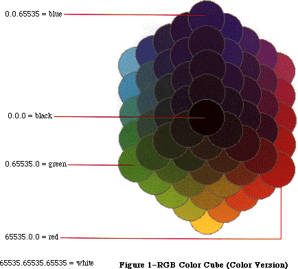 Figure 1–RGB Color Cube (Color Version)
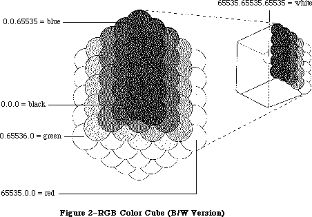 Figure 2–RGB Color Cube (B/W Version)
The data structures used within Color Quickdraw express each RGB component as an unsigned integer value. Each R, G, and B can have a value from $0000 to $FFFF (or 0 to 65,535). RGB color is additive; that is, as the value of a component is increased, the amount of that component in the total color increases. An RGB color is black if all three components are set to 0, or white if each component is set to 65,535. Pixel values between these two extremes can be combined to represent all the possible colors. For instance, pixel values that lie along the diagonal between black and white, and for which R = G = B, are all perceived as shades of gray.
_______________________________________________________________________________
»Other Color Spaces
In addition to RGB, several other color models are commonly used to represent colors. These other models include HSV (hue, saturation, value), HLS (hue, lightness, saturation), and CMY (cyan, magenta, yellow). If you wish to work in a different color space in your program, you can use the conversion routines provided in the Color Picker Package to convert colors to their RGB equivalents before passing them to Color QuickDraw. Please refer to the Color Picker Package chapter for more details.
_______________________________________________________________________________
»USING COLOR ON THE MACINTOSH II
_______________________________________________________________________________
Before you read about the details of how to use Color QuickDraw, it’s useful to understand the various components of the color system and how they interact with each other. This section, through a series of rules and examples, attempts to illustrate these interactions.
Rule 1: The user selects the depth of the screen using the Control Panel.
This rule is mentioned first to convey the fundamental need for device independence. Your application shouldn’t change the depth of the screen, because it must avoid conflicts with desk accessories or other applications that are using the screen at the same time. Let the user decide how many colors should be displayed.
Rule 2: Work with colors in RGB space, not with the colors on the screen.
Whenever possible, your application should assume that it’s drawing to a screen that has 2^48 colors. Let Color QuickDraw determine what colors to actually display on the screen. This lets your program work better when drawing to devices that support more colors.
The easiest way to follow this rule is for a program to call the Color Picker Package to select colors. The Color Picker returns an RGB value, which can then be used as the current color. When Color QuickDraw draws using that color, it selects the color that best matches the specified RGB.
Rule 3: To ensure good color matching, and to avoid conflict with other applications and desk accessories, use the Palette Manager.
If your program requires a very specific set of colors not found in the default selection of colors, for instance 128 levels of gray, then you should use the Palette Manager. The Palette Manager lets you specify the set of colors that is to be used by a particular window. When that window is brought to the front, its set of colors is switched in (with a minimal amount of impact on the rest of the screen).
You should also use the Palette Manager if your application needs to animate colors (that is, to change the colors of pixels that are already displayed).
The Palette Manager is a powerful tool because it makes sure that your application gets the best selection of colors across multiple screen devices and multiple screen depths. You don’t have to worry about interactions with desk accessories or other applications. Please refer to the chapter on the Palette Manager for more information on using the Palette Manager routines.
Rule 4: Be aware that systems may have multiple video devices.
Since the Macintosh II is able to support multiple screen devices, make sure your application takes into account the variable-sized desktop. For instance, a document may have been dragged to an alternate screen on one system, and then copied and used on another system. You should leave the document positioned where it is if it lies within the desktop, but move it to the main screen if it doesn’t. Please refer to the Graphics Devices chapter for more details.
Figure 3 helps to illustrate the relationships between the various parts of the color system.
Figure 2–RGB Color Cube (B/W Version)
The data structures used within Color Quickdraw express each RGB component as an unsigned integer value. Each R, G, and B can have a value from $0000 to $FFFF (or 0 to 65,535). RGB color is additive; that is, as the value of a component is increased, the amount of that component in the total color increases. An RGB color is black if all three components are set to 0, or white if each component is set to 65,535. Pixel values between these two extremes can be combined to represent all the possible colors. For instance, pixel values that lie along the diagonal between black and white, and for which R = G = B, are all perceived as shades of gray.
_______________________________________________________________________________
»Other Color Spaces
In addition to RGB, several other color models are commonly used to represent colors. These other models include HSV (hue, saturation, value), HLS (hue, lightness, saturation), and CMY (cyan, magenta, yellow). If you wish to work in a different color space in your program, you can use the conversion routines provided in the Color Picker Package to convert colors to their RGB equivalents before passing them to Color QuickDraw. Please refer to the Color Picker Package chapter for more details.
_______________________________________________________________________________
»USING COLOR ON THE MACINTOSH II
_______________________________________________________________________________
Before you read about the details of how to use Color QuickDraw, it’s useful to understand the various components of the color system and how they interact with each other. This section, through a series of rules and examples, attempts to illustrate these interactions.
Rule 1: The user selects the depth of the screen using the Control Panel.
This rule is mentioned first to convey the fundamental need for device independence. Your application shouldn’t change the depth of the screen, because it must avoid conflicts with desk accessories or other applications that are using the screen at the same time. Let the user decide how many colors should be displayed.
Rule 2: Work with colors in RGB space, not with the colors on the screen.
Whenever possible, your application should assume that it’s drawing to a screen that has 2^48 colors. Let Color QuickDraw determine what colors to actually display on the screen. This lets your program work better when drawing to devices that support more colors.
The easiest way to follow this rule is for a program to call the Color Picker Package to select colors. The Color Picker returns an RGB value, which can then be used as the current color. When Color QuickDraw draws using that color, it selects the color that best matches the specified RGB.
Rule 3: To ensure good color matching, and to avoid conflict with other applications and desk accessories, use the Palette Manager.
If your program requires a very specific set of colors not found in the default selection of colors, for instance 128 levels of gray, then you should use the Palette Manager. The Palette Manager lets you specify the set of colors that is to be used by a particular window. When that window is brought to the front, its set of colors is switched in (with a minimal amount of impact on the rest of the screen).
You should also use the Palette Manager if your application needs to animate colors (that is, to change the colors of pixels that are already displayed).
The Palette Manager is a powerful tool because it makes sure that your application gets the best selection of colors across multiple screen devices and multiple screen depths. You don’t have to worry about interactions with desk accessories or other applications. Please refer to the chapter on the Palette Manager for more information on using the Palette Manager routines.
Rule 4: Be aware that systems may have multiple video devices.
Since the Macintosh II is able to support multiple screen devices, make sure your application takes into account the variable-sized desktop. For instance, a document may have been dragged to an alternate screen on one system, and then copied and used on another system. You should leave the document positioned where it is if it lies within the desktop, but move it to the main screen if it doesn’t. Please refer to the Graphics Devices chapter for more details.
Figure 3 helps to illustrate the relationships between the various parts of the color system.
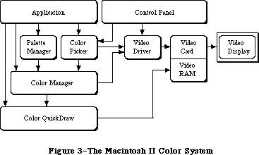 Figure 3–The Macintosh II Color System
_______________________________________________________________________________
»From Color to Pixel
To help illustrate the interconnections of the color system, let’s examine the steps from the specification of a color to the display of that color on the screen. This is an oversimplified explanation that you should use for conceptual understanding only.
First, you specify the color that you want to display. Color QuickDraw stores the RGB components so that it knows the exact color that you specified. Let’s assume that the screen is set to eight bits per pixel. This means that each pixel is able to have 2^8, or 256, different values. Associated with the screen is a structure called a color table, which is a list of all the colors that the screen is currently able to display. So in this case the color table has 256 RGB values in it, one for each possible pixel value. The first entry in the color table specifies the color of all pixels that have value 0, the second entry specifies the color of pixels that have value 1, and so on. Thus the color’s position in the table determines the pixel value that produces that color.
When you use Color QuickDraw to draw something, it retrieves the stored RGB, and asks the Color Manager to return the pixel value that best represents that color. The Color Manager effectively searches through the color table for the RGB that most closely matches your color. The position in the table of the best match determines the pixel value to be placed on the screen. Color QuickDraw then places that pixel value on the screen.
But how does this pixel cause the assigned color to be displayed? Color QuickDraw has placed this pixel into the RAM on the video card. While your Macintosh II is turned on, the video card is continuously redisplaying every pixel that is stored in its RAM (very, very quickly). Internal to the video card is another color table, the Color Look-Up Table (CLUT). It is organized exactly like the first one, but is used the other way around. The video card takes the pixel value and uses it to determine what RGB value that pixel represents. It then uses that RGB to send off three signals (red, green, and blue) to the video monitor, indicating exactly what color the current pixel should be.
Some video cards allow you to change the set of colors displayed at a given time. Although this is normally done transparently through the Palette Manager, it actually happens when both the screen’s color table and the one that is internal to the video card are changed to reflect the new set of colors.
A very slight variation of this is used to support the monochrome mode that you can set from the control panel. When you set monochrome mode, the screen’s color table doesn’t change: from the application’s point of view, the same set of colors is still available. Instead, when the video card is told to use monochrome mode, it replaces each entry in the video card’s internal color table with a level of gray (R=G=B) that matches the luminance of the color it is replacing. Because of this, the switch between color and monochrome modes has no effect on a running program.
_______________________________________________________________________________
»ABOUT COLOR QUICKDRAW
_______________________________________________________________________________
The most fundamental difference between the original QuickDraw and Color QuickDraw is the environment in which drawing takes place. In the original QuickDraw, all drawing is performed in a grafPort, the structure that defines the coordinate system, drawing pattern, background pattern, pen size and location, character font and style, and bit map in which drawing takes place. In Color QuickDraw, drawing takes place in a color grafPort (cGrafPort) instead. As described in later sections, most of the fields in a cGrafPort are the same as fields in a grafPort; however, a few fields have been changed to hold color information.
When you’re using a grafPort in your application, you can specify up to eight colors. When drawing to a color screen or printing, these colors will actually be displayed. When drawing to an offscreen bitmap, the colors will be lost
(since an offscreen bitmap only has one bit for each pixel).
When you’re using a cGrafPort, however, you can specify up to 2^48 colors. The number of colors that are displayed depends on the setting of the screen, the capability of the printer, or the depth of the offscreen pixmap. There is more information about offscreen pixmaps in the “Drawing to Offscreen Devices” section of the next chapter.
Color grafPorts are used by the system in the same way as grafPorts. They are the same size as grafPorts, and they are the structures upon which a program builds color windows. As with a grafPort, you set thePort to be a cGrafPort using the SetPort command.
You can use all old drawing commands when drawing into a cGrafPort, and you can use all new drawing commands when drawing into a grafPort. However, since new drawing commands that are used in a grafPort don’t take advantage of any of the features of Color QuickDraw, it’s not recommended.
_______________________________________________________________________________
»Drawing Color in a GrafPort
Although the QuickDraw graphics routines were designed mainly for monochrome drawing, they also included some rudimentary color capabilities. A pair of fields in the grafPort record, fgColor and bkColor, allow a foreground and background color to be specified. The color values used in these fields are based on a planar model: each bit position corresponds to a different color plane, and the value of each bit indicates whether a particular color plane should be activated. (The term color plane refers to a logical plane, rather than a physical plane.) The individual color planes combine to produce the
full-color image.
The standard QuickDraw color values consist of one bit for normal monochrome drawing (black on white), one bit for inverted monochrome (white on black), three bits for the additive primary colors (red, green, blue) used in video display, and four bits for the subtractive primary colors (cyan, magenta, yellow, black) used in hardcopy printing. The original QuickDraw interface includes a set of predefined constants for the standard colors:
CONST
blackColor = 33;
whiteColor = 30;
redColor = 209;
greenColor = 329;
blueColor = 389;
cyanColor = 269;
magentaColor = 149;
yellowColor = 89;
These are the only colors available in the original QuickDraw. All programs that draw into grafPorts are limited to these eight colors. When these colors are drawn to the screen on the Macintosh II, Color QuickDraw automatically draws them in color, if the screen is set to a color mode.
_______________________________________________________________________________
»Drawing Color in a CGrafPort
Color QuickDraw represents color using the RGBColor record type, which specifies the red, blue, and green components of the color. Three 16-bit unsigned integers give the intensity values for the three additive primary colors:
TYPE
RGBColor = RECORD
red: INTEGER; {red component}
green: INTEGER; {green component}
blue: INTEGER {blue component}
END;
A color of this form is referred to as an RGB value and is the form in which an application specifies the colors it needs. The translation from the RGB value to the pixel value is performed at the time the color is drawn. At times the pixel value is stored in the fgColor or bkColor fields. Refer to the Graphics Devices chapter for more details.
When drawing is actually performed, QuickDraw calls the Color Manager to supply the color that most closely matches the requested color for the current device. As described in the Color Manager chapter, you can replace the method used for color matching if necessary. Normally pixel values are handled entirely by Color QuickDraw and the Color Manager; applications only refer to colors as RGB values.
A set of colors is grouped into a structure called a color table:
TYPE
CTabHandle = ^CTabPtr;
CTabPtr = ^ColorTable;
ColorTable = RECORD
ctSeed: LONGINT; {unique identifier from table}
ctFlags: INTEGER; {contains flags describing the }
{ specArray; clear for a pixMap}
ctSize: INTEGER; {number of entries -1 }
{ in ctTable}
ctTable: cSpecArray
END;
The fields of a color table are fully described in the Color Manager chapter. The ctFlags field contains flags that differentiate between a device color table and an image color table. The ctTable field is composed of a cSpecArray, which contains an array of ColorSpec entries. Notice that each entry in the color table is a ColorSpec, not simply an RGBColor. The type ColorSpec is composed of a value field and an RGB value, as shown below.
TYPE
cSpecArray : ARRAY [0..0] of ColorSpec;
ColorSpec = RECORD
value: INTEGER; {pixel value}
rgb: RGBColor {RGB value}
END;
Color tables are used to represent the set of colors that a device is capable of displaying, and they are used to describe the desired colors in an image. If the color table describes an image’s colors, then a ColorSpec determines the desired RGB for the pixel value stored in the value field. This is the most common usage, and most of the routines described in this chapter work with a ColorSpec in this manner.
If the color table describes a device’s colors, then the value field in a ColorSpec is reserved for use by the Color Manager. In most cases your application won’t change the device color table. If you want to know more about the device color table, refer to the Color Manager chapter for more details.
_______________________________________________________________________________
»THE COLOR GRAPHICS PORT
_______________________________________________________________________________
As described above, programs designed to take advantage of the more powerful new color facilities available on the Macintosh II must use a new form of graphics port, the color graphics port (type cGrafPort). Color grafPorts will generally be created indirectly, as a result of opening a color window with the new routines NewCWindow, GetNewCWindow, and NewCDialog.
In addition, the old routines GetNewWindow, GetNewDialog, Alert, StopAlert, NoteAlert, and CautionAlert will open a color grafPort if certain resources
(types 'wctb', 'dctb', or 'actb') are present. Refer to the chapters on the Window and Dialog Managers for more details.
The new cGrafPort structure is the same size as the old-style grafPort and most of its fields are unchanged. The old portBits field, which formerly held a complete 14-byte BitMap record embedded within the grafPort, has been replaced by a 4-byte PixMapHandle (portPixMap), freeing 10 bytes for other uses. (In particular, the new portVersion field, in the position previously occupied by the bit map’s rowBytes field, always has its two high
bits set; these bits are used to distinguish cGrafPorts from grafPorts, in which the two high bits of rowBytes are always clear. See Figure 4.) Similarly, the old bkPat, pnPat, and fillPat fields, which previously held 8-byte patterns, have been replaced by three 4-byte handles. The resulting 12 bytes of additional space are taken up by two 6-byte RGBColor records.
The structure of the color graphics port is as follows:
CGrafPtr = ^CGrafPort;
CGrafPort = RECORD
device: INTEGER; {device ID for font }
{ selection}
portPixMap: PixMapHandle; {port's pixel map}
portVersion: INTEGER; {highest 2 bits always }
{ set}
grafVars: Handle; {handle to more fields}
chExtra: INTEGER; {extra characters}
pnLocHFrac: INTEGER; {pen fraction}
portRect: Rect; {port rectangle}
visRgn: RgnHandle; {visible region}
clipRgn: RgnHandle; {clipping region}
bkPixPat: PixPatHandle; {background pattern}
rgbFgColor: RGBColor; {requested foreground }
{ color}
rgbBkColor: RGBColor; {requested background }
{ color}
pnLoc: Point; {pen location}
pnSize: Point; {pen size}
pnMode: INTEGER; {pen transfer mode}
pnPixPat: PixPatHandle; {pen pattern}
fillPixPat: PixPatHandle; {fill pattern}
pnVis: INTEGER; {pen visibility}
txFont: INTEGER; {font number for text}
txFace: Style; {text's character style}
txMode: INTEGER; {text's transfer mode}
txSize: INTEGER; {font size for text}
spExtra: Fixed; {extra space}
fgColor: LONGINT; {actual foreground color}
bkColor: LONGINT; {actual background color}
colrBit: INTEGER; {plane being drawn}
patStretch: INTEGER; {used internally}
picSave: Handle; {picture being saved}
rgnSave: Handle; {region being saved}
polySave: Handle; {polygon being saved}
grafProcs: CQDProcsPtr {low-level drawing }
{ routines}
END;
Field descriptions
portPixMap The portPixMap field contains a handle to the port’s pixel
map. This is the structure that describes the cGrafPort’s pixels.
portVersion The two high bits of the portVersion field are always set.
This allows Color QuickDraw to tell the difference between a
grafPort and a cGrafPort. The remainder of the field gives
the version number of Color QuickDraw that created this port.
(Initial release is version 0.)
grafVars The grafVars field contains a handle to additional fields.
chExtra The chExtra field is used in proportional spacing. It specifies
a fixed point number by which to widen every character,
excluding the space character, in a line of text. (The number
is in 4.12 fractional notation: four bits of signed integer
followed by 12 bits of fraction. This number is multiplied by
txSize before it is used.) Default chExtra is 0.
pnLocHFrac The pnLocHFrac field contains the fractional horizontal pen
position used when drawing text. The initial pen fraction is 1/2.
bkPixPat The bkPixPat field contains a handle to the background pixel
pattern.
rgbFgColor The rgbFgColor field contains the requested foreground color.
rgbBkColor The rgbBkColor field contains the requested background color.
pnPixPat The pnPixPat field contains a handle to the pixel pattern for
pen drawing.
fillPixPat The fillPixPat field contains a handle to the pixel pattern for
area fill; for internal use only. Notice that this is not in
the same location as old fillPat.
fgColor The fgColor field contains the pixel value of the foreground
color supplied by the Color Manager. This is the best available
approximation to rgbFgColor.
bkColor The bkColor field contains the pixel value of the background
color supplied by the Color Manager. This is the best available
approximation to rgbBkColor.
colrBit The colrBit field is reserved: not for use by applications.
grafProc The grafProc field used with a cGrafPort contains a CQDProcsPtr,
instead of the QDProcsPtr used with a grafPort.
All remaining fields have the same meanings as in the old-style grafPort.
Figure 3–The Macintosh II Color System
_______________________________________________________________________________
»From Color to Pixel
To help illustrate the interconnections of the color system, let’s examine the steps from the specification of a color to the display of that color on the screen. This is an oversimplified explanation that you should use for conceptual understanding only.
First, you specify the color that you want to display. Color QuickDraw stores the RGB components so that it knows the exact color that you specified. Let’s assume that the screen is set to eight bits per pixel. This means that each pixel is able to have 2^8, or 256, different values. Associated with the screen is a structure called a color table, which is a list of all the colors that the screen is currently able to display. So in this case the color table has 256 RGB values in it, one for each possible pixel value. The first entry in the color table specifies the color of all pixels that have value 0, the second entry specifies the color of pixels that have value 1, and so on. Thus the color’s position in the table determines the pixel value that produces that color.
When you use Color QuickDraw to draw something, it retrieves the stored RGB, and asks the Color Manager to return the pixel value that best represents that color. The Color Manager effectively searches through the color table for the RGB that most closely matches your color. The position in the table of the best match determines the pixel value to be placed on the screen. Color QuickDraw then places that pixel value on the screen.
But how does this pixel cause the assigned color to be displayed? Color QuickDraw has placed this pixel into the RAM on the video card. While your Macintosh II is turned on, the video card is continuously redisplaying every pixel that is stored in its RAM (very, very quickly). Internal to the video card is another color table, the Color Look-Up Table (CLUT). It is organized exactly like the first one, but is used the other way around. The video card takes the pixel value and uses it to determine what RGB value that pixel represents. It then uses that RGB to send off three signals (red, green, and blue) to the video monitor, indicating exactly what color the current pixel should be.
Some video cards allow you to change the set of colors displayed at a given time. Although this is normally done transparently through the Palette Manager, it actually happens when both the screen’s color table and the one that is internal to the video card are changed to reflect the new set of colors.
A very slight variation of this is used to support the monochrome mode that you can set from the control panel. When you set monochrome mode, the screen’s color table doesn’t change: from the application’s point of view, the same set of colors is still available. Instead, when the video card is told to use monochrome mode, it replaces each entry in the video card’s internal color table with a level of gray (R=G=B) that matches the luminance of the color it is replacing. Because of this, the switch between color and monochrome modes has no effect on a running program.
_______________________________________________________________________________
»ABOUT COLOR QUICKDRAW
_______________________________________________________________________________
The most fundamental difference between the original QuickDraw and Color QuickDraw is the environment in which drawing takes place. In the original QuickDraw, all drawing is performed in a grafPort, the structure that defines the coordinate system, drawing pattern, background pattern, pen size and location, character font and style, and bit map in which drawing takes place. In Color QuickDraw, drawing takes place in a color grafPort (cGrafPort) instead. As described in later sections, most of the fields in a cGrafPort are the same as fields in a grafPort; however, a few fields have been changed to hold color information.
When you’re using a grafPort in your application, you can specify up to eight colors. When drawing to a color screen or printing, these colors will actually be displayed. When drawing to an offscreen bitmap, the colors will be lost
(since an offscreen bitmap only has one bit for each pixel).
When you’re using a cGrafPort, however, you can specify up to 2^48 colors. The number of colors that are displayed depends on the setting of the screen, the capability of the printer, or the depth of the offscreen pixmap. There is more information about offscreen pixmaps in the “Drawing to Offscreen Devices” section of the next chapter.
Color grafPorts are used by the system in the same way as grafPorts. They are the same size as grafPorts, and they are the structures upon which a program builds color windows. As with a grafPort, you set thePort to be a cGrafPort using the SetPort command.
You can use all old drawing commands when drawing into a cGrafPort, and you can use all new drawing commands when drawing into a grafPort. However, since new drawing commands that are used in a grafPort don’t take advantage of any of the features of Color QuickDraw, it’s not recommended.
_______________________________________________________________________________
»Drawing Color in a GrafPort
Although the QuickDraw graphics routines were designed mainly for monochrome drawing, they also included some rudimentary color capabilities. A pair of fields in the grafPort record, fgColor and bkColor, allow a foreground and background color to be specified. The color values used in these fields are based on a planar model: each bit position corresponds to a different color plane, and the value of each bit indicates whether a particular color plane should be activated. (The term color plane refers to a logical plane, rather than a physical plane.) The individual color planes combine to produce the
full-color image.
The standard QuickDraw color values consist of one bit for normal monochrome drawing (black on white), one bit for inverted monochrome (white on black), three bits for the additive primary colors (red, green, blue) used in video display, and four bits for the subtractive primary colors (cyan, magenta, yellow, black) used in hardcopy printing. The original QuickDraw interface includes a set of predefined constants for the standard colors:
CONST
blackColor = 33;
whiteColor = 30;
redColor = 209;
greenColor = 329;
blueColor = 389;
cyanColor = 269;
magentaColor = 149;
yellowColor = 89;
These are the only colors available in the original QuickDraw. All programs that draw into grafPorts are limited to these eight colors. When these colors are drawn to the screen on the Macintosh II, Color QuickDraw automatically draws them in color, if the screen is set to a color mode.
_______________________________________________________________________________
»Drawing Color in a CGrafPort
Color QuickDraw represents color using the RGBColor record type, which specifies the red, blue, and green components of the color. Three 16-bit unsigned integers give the intensity values for the three additive primary colors:
TYPE
RGBColor = RECORD
red: INTEGER; {red component}
green: INTEGER; {green component}
blue: INTEGER {blue component}
END;
A color of this form is referred to as an RGB value and is the form in which an application specifies the colors it needs. The translation from the RGB value to the pixel value is performed at the time the color is drawn. At times the pixel value is stored in the fgColor or bkColor fields. Refer to the Graphics Devices chapter for more details.
When drawing is actually performed, QuickDraw calls the Color Manager to supply the color that most closely matches the requested color for the current device. As described in the Color Manager chapter, you can replace the method used for color matching if necessary. Normally pixel values are handled entirely by Color QuickDraw and the Color Manager; applications only refer to colors as RGB values.
A set of colors is grouped into a structure called a color table:
TYPE
CTabHandle = ^CTabPtr;
CTabPtr = ^ColorTable;
ColorTable = RECORD
ctSeed: LONGINT; {unique identifier from table}
ctFlags: INTEGER; {contains flags describing the }
{ specArray; clear for a pixMap}
ctSize: INTEGER; {number of entries -1 }
{ in ctTable}
ctTable: cSpecArray
END;
The fields of a color table are fully described in the Color Manager chapter. The ctFlags field contains flags that differentiate between a device color table and an image color table. The ctTable field is composed of a cSpecArray, which contains an array of ColorSpec entries. Notice that each entry in the color table is a ColorSpec, not simply an RGBColor. The type ColorSpec is composed of a value field and an RGB value, as shown below.
TYPE
cSpecArray : ARRAY [0..0] of ColorSpec;
ColorSpec = RECORD
value: INTEGER; {pixel value}
rgb: RGBColor {RGB value}
END;
Color tables are used to represent the set of colors that a device is capable of displaying, and they are used to describe the desired colors in an image. If the color table describes an image’s colors, then a ColorSpec determines the desired RGB for the pixel value stored in the value field. This is the most common usage, and most of the routines described in this chapter work with a ColorSpec in this manner.
If the color table describes a device’s colors, then the value field in a ColorSpec is reserved for use by the Color Manager. In most cases your application won’t change the device color table. If you want to know more about the device color table, refer to the Color Manager chapter for more details.
_______________________________________________________________________________
»THE COLOR GRAPHICS PORT
_______________________________________________________________________________
As described above, programs designed to take advantage of the more powerful new color facilities available on the Macintosh II must use a new form of graphics port, the color graphics port (type cGrafPort). Color grafPorts will generally be created indirectly, as a result of opening a color window with the new routines NewCWindow, GetNewCWindow, and NewCDialog.
In addition, the old routines GetNewWindow, GetNewDialog, Alert, StopAlert, NoteAlert, and CautionAlert will open a color grafPort if certain resources
(types 'wctb', 'dctb', or 'actb') are present. Refer to the chapters on the Window and Dialog Managers for more details.
The new cGrafPort structure is the same size as the old-style grafPort and most of its fields are unchanged. The old portBits field, which formerly held a complete 14-byte BitMap record embedded within the grafPort, has been replaced by a 4-byte PixMapHandle (portPixMap), freeing 10 bytes for other uses. (In particular, the new portVersion field, in the position previously occupied by the bit map’s rowBytes field, always has its two high
bits set; these bits are used to distinguish cGrafPorts from grafPorts, in which the two high bits of rowBytes are always clear. See Figure 4.) Similarly, the old bkPat, pnPat, and fillPat fields, which previously held 8-byte patterns, have been replaced by three 4-byte handles. The resulting 12 bytes of additional space are taken up by two 6-byte RGBColor records.
The structure of the color graphics port is as follows:
CGrafPtr = ^CGrafPort;
CGrafPort = RECORD
device: INTEGER; {device ID for font }
{ selection}
portPixMap: PixMapHandle; {port's pixel map}
portVersion: INTEGER; {highest 2 bits always }
{ set}
grafVars: Handle; {handle to more fields}
chExtra: INTEGER; {extra characters}
pnLocHFrac: INTEGER; {pen fraction}
portRect: Rect; {port rectangle}
visRgn: RgnHandle; {visible region}
clipRgn: RgnHandle; {clipping region}
bkPixPat: PixPatHandle; {background pattern}
rgbFgColor: RGBColor; {requested foreground }
{ color}
rgbBkColor: RGBColor; {requested background }
{ color}
pnLoc: Point; {pen location}
pnSize: Point; {pen size}
pnMode: INTEGER; {pen transfer mode}
pnPixPat: PixPatHandle; {pen pattern}
fillPixPat: PixPatHandle; {fill pattern}
pnVis: INTEGER; {pen visibility}
txFont: INTEGER; {font number for text}
txFace: Style; {text's character style}
txMode: INTEGER; {text's transfer mode}
txSize: INTEGER; {font size for text}
spExtra: Fixed; {extra space}
fgColor: LONGINT; {actual foreground color}
bkColor: LONGINT; {actual background color}
colrBit: INTEGER; {plane being drawn}
patStretch: INTEGER; {used internally}
picSave: Handle; {picture being saved}
rgnSave: Handle; {region being saved}
polySave: Handle; {polygon being saved}
grafProcs: CQDProcsPtr {low-level drawing }
{ routines}
END;
Field descriptions
portPixMap The portPixMap field contains a handle to the port’s pixel
map. This is the structure that describes the cGrafPort’s pixels.
portVersion The two high bits of the portVersion field are always set.
This allows Color QuickDraw to tell the difference between a
grafPort and a cGrafPort. The remainder of the field gives
the version number of Color QuickDraw that created this port.
(Initial release is version 0.)
grafVars The grafVars field contains a handle to additional fields.
chExtra The chExtra field is used in proportional spacing. It specifies
a fixed point number by which to widen every character,
excluding the space character, in a line of text. (The number
is in 4.12 fractional notation: four bits of signed integer
followed by 12 bits of fraction. This number is multiplied by
txSize before it is used.) Default chExtra is 0.
pnLocHFrac The pnLocHFrac field contains the fractional horizontal pen
position used when drawing text. The initial pen fraction is 1/2.
bkPixPat The bkPixPat field contains a handle to the background pixel
pattern.
rgbFgColor The rgbFgColor field contains the requested foreground color.
rgbBkColor The rgbBkColor field contains the requested background color.
pnPixPat The pnPixPat field contains a handle to the pixel pattern for
pen drawing.
fillPixPat The fillPixPat field contains a handle to the pixel pattern for
area fill; for internal use only. Notice that this is not in
the same location as old fillPat.
fgColor The fgColor field contains the pixel value of the foreground
color supplied by the Color Manager. This is the best available
approximation to rgbFgColor.
bkColor The bkColor field contains the pixel value of the background
color supplied by the Color Manager. This is the best available
approximation to rgbBkColor.
colrBit The colrBit field is reserved: not for use by applications.
grafProc The grafProc field used with a cGrafPort contains a CQDProcsPtr,
instead of the QDProcsPtr used with a grafPort.
All remaining fields have the same meanings as in the old-style grafPort.
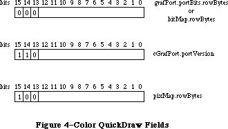 Figure 4–Color QuickDraw Fields
_______________________________________________________________________________
»Pixel Images
The representation of a color image in memory is a pixel image, analogous to the bit image used by the original QuickDraw. The number of bits per pixel is called the depth of the image; a pixel image one bit deep is equivalent to a bit image. On the Macintosh II, the pixel image that appears on a video screen is normally stored on a graphics card rather than in main memory. To increase speed, your program can build additional images in RAM for rapid transfer to the display device. This technique, called drawing to an offscreen bitmap, is described in the Graphics Devices chapter.
There are several possible arrangements of a pixel image in memory. The size and structure of a pixel image is described by the pixel map data structure; this structure and its various forms are discussed below. See Figure 5 for a representation of a pixel image on a system with screen depth set to eight.
_______________________________________________________________________________
»Pixel Maps
Just as the original QuickDraw does all of its drawing in a bit map, Color QuickDraw uses an extended data structure called a pixel map (pixMap). In addition to the dimensions and contents of a pixel image, the pixel map also includes information on the image’s storage format, depth, resolution, and color usage:
TYPE
PixMapHandle = ^PixMapPtr;
PixMapPtr = ^PixMap;
PixMap = RECORD
baseAddr: Ptr; {pointer to pixMap data}
rowBytes: INTEGER; {offset to next row}
bounds: Rect; {boundary rectangle}
pmVersion: INTEGER; {color QuickDraw version }
{ number}
packType: INTEGER; {packing format}
packSize: LONGINT; {size of data in packed }
{ state}
hRes: Fixed; {horizontal resolution}
vRes: Fixed; {vertical resolution}
pixelType: INTEGER; {format of pixel image}
pixelSize: INTEGER; {physical bits per pixel}
cmpCount: INTEGER; {logical components per }
{ pixel}
cmpSize: INTEGER; {logical bits per component}
planeBytes: LONGINT; {offset to next plane}
pmTable: CTabHandle; {absolute colors for this }
{ image}
pmReserved: LONGINT {reserved for future }
{ expansion}
END;
Field descriptions
baseAddr The baseAddr field contains a pointer to first byte of the
pixel image, the same as in a bitMap. For optimal performance
this should be a multiple of four.
rowBytes The rowBytes field contains the offset in bytes from one row of
the image to the next, the same as in a bitMap. As before,
rowBytes must be even. The high three bits of rowBytes are used
as flags. If bit 15 = 1, the data structure is a pixMap;
otherwise it is a bitMap. Bits 14 and 13 are not used and must
be 0.
bounds The bounds field is the boundary rectangle, which defines the
coordinate system and extent of the pixel map; it’s similar to
a bitMap. This rectangle is in pixels, so depth has no effect
on its values.
pmVersion The pmVersion is the version number of Color QuickDraw that
created this pixel map, which is provided for future
compatibility. (Initial release is version 0.)
packType The packType field identifies the packing algorithm used to
compress image data. Color QuickDraw currently supports only
packType = 0, which means no packing.
packSize The packSize field contains the size of the packed image in
bytes. When packType = 0, this field should be set to 0.
hRes The hRes is the horizontal resolution of pixMap data in pixels
per inch.
vRes The vRes is the vertical resolution of pixMap data in pixels
per inch. By default, hRes = vRes = 72 pixels per inch.
pixelType The pixelType field specifies the storage format for a pixel
image. 0 = chunky, 1 = chunky/planar, 2 = planar. Only chunky
is used in the Macintosh II.
pixelSize The pixelSize is the physical bits per pixel; it’s always a
power of 2.
cmpCount The cmpCount is the number of color components per pixel. For
chunky pixel images, this is always 1.
cmpSize The cmpSize field contains the logical bits per RGBColor
component. Note that (cmpCount*cmpSize) doesn’t necessarily
equal pixelSize. For chunky pixel images, cmpSize = pixelSize.
planeBytes The planeBytes field is the offset in bytes from one plane to
the next. If only one plane is used, as is the case with chunky
pixel images, this field is set to 0.
pmTable The pmTable field is a handle to table of colors used in the
pixMap. This may be a device color table or an image color table.
pmReserved The pmReserved field is reserved for future expansion; it must
be set to 0 for future compatibility.
The data in a pixel image can be organized several ways, depending on the characteristics of the device or image. The pixMap data structure supports three pixel image formats: chunky, planar, and chunky/planar.
In a chunky pixel image, all of a pixel’s bits are stored consecutively in memory, all of a row’s pixels are stored consecutively, and rowBytes indicates the offset in memory from one row to the next. This is the only one of the three formats that’s supported by this implementation of Color QuickDraw. The pixel depths that are currently supported are 1, 2, 4, and 8 bits per pixel. In a chunky pixMap cmpCount = 1 and cmpSize = pixelSize. Figure 5 shows a chunky pixel image for a system with screen depth set to eight.
A planar pixel image is a pixel image separated into distinct bit images in memory, one for each color plane. Within the bit image, rowBytes indicates the offset in memory from one row to the next. PlaneBytes indicates the offset in memory from one plane to the next. The planar format isn’t supported by this implementation of Color QuickDraw.
A chunky/planar pixel image is separated into distinct pixel images in memory, typically one for each color component. Within the pixel image, rowBytes indicates the offset in memory from one row to the next. PlaneBytes indicates the offset in memory from one plane to the next. The chunky/planar format isn’t supported by this implementation of Color QuickDraw.
Figure 4–Color QuickDraw Fields
_______________________________________________________________________________
»Pixel Images
The representation of a color image in memory is a pixel image, analogous to the bit image used by the original QuickDraw. The number of bits per pixel is called the depth of the image; a pixel image one bit deep is equivalent to a bit image. On the Macintosh II, the pixel image that appears on a video screen is normally stored on a graphics card rather than in main memory. To increase speed, your program can build additional images in RAM for rapid transfer to the display device. This technique, called drawing to an offscreen bitmap, is described in the Graphics Devices chapter.
There are several possible arrangements of a pixel image in memory. The size and structure of a pixel image is described by the pixel map data structure; this structure and its various forms are discussed below. See Figure 5 for a representation of a pixel image on a system with screen depth set to eight.
_______________________________________________________________________________
»Pixel Maps
Just as the original QuickDraw does all of its drawing in a bit map, Color QuickDraw uses an extended data structure called a pixel map (pixMap). In addition to the dimensions and contents of a pixel image, the pixel map also includes information on the image’s storage format, depth, resolution, and color usage:
TYPE
PixMapHandle = ^PixMapPtr;
PixMapPtr = ^PixMap;
PixMap = RECORD
baseAddr: Ptr; {pointer to pixMap data}
rowBytes: INTEGER; {offset to next row}
bounds: Rect; {boundary rectangle}
pmVersion: INTEGER; {color QuickDraw version }
{ number}
packType: INTEGER; {packing format}
packSize: LONGINT; {size of data in packed }
{ state}
hRes: Fixed; {horizontal resolution}
vRes: Fixed; {vertical resolution}
pixelType: INTEGER; {format of pixel image}
pixelSize: INTEGER; {physical bits per pixel}
cmpCount: INTEGER; {logical components per }
{ pixel}
cmpSize: INTEGER; {logical bits per component}
planeBytes: LONGINT; {offset to next plane}
pmTable: CTabHandle; {absolute colors for this }
{ image}
pmReserved: LONGINT {reserved for future }
{ expansion}
END;
Field descriptions
baseAddr The baseAddr field contains a pointer to first byte of the
pixel image, the same as in a bitMap. For optimal performance
this should be a multiple of four.
rowBytes The rowBytes field contains the offset in bytes from one row of
the image to the next, the same as in a bitMap. As before,
rowBytes must be even. The high three bits of rowBytes are used
as flags. If bit 15 = 1, the data structure is a pixMap;
otherwise it is a bitMap. Bits 14 and 13 are not used and must
be 0.
bounds The bounds field is the boundary rectangle, which defines the
coordinate system and extent of the pixel map; it’s similar to
a bitMap. This rectangle is in pixels, so depth has no effect
on its values.
pmVersion The pmVersion is the version number of Color QuickDraw that
created this pixel map, which is provided for future
compatibility. (Initial release is version 0.)
packType The packType field identifies the packing algorithm used to
compress image data. Color QuickDraw currently supports only
packType = 0, which means no packing.
packSize The packSize field contains the size of the packed image in
bytes. When packType = 0, this field should be set to 0.
hRes The hRes is the horizontal resolution of pixMap data in pixels
per inch.
vRes The vRes is the vertical resolution of pixMap data in pixels
per inch. By default, hRes = vRes = 72 pixels per inch.
pixelType The pixelType field specifies the storage format for a pixel
image. 0 = chunky, 1 = chunky/planar, 2 = planar. Only chunky
is used in the Macintosh II.
pixelSize The pixelSize is the physical bits per pixel; it’s always a
power of 2.
cmpCount The cmpCount is the number of color components per pixel. For
chunky pixel images, this is always 1.
cmpSize The cmpSize field contains the logical bits per RGBColor
component. Note that (cmpCount*cmpSize) doesn’t necessarily
equal pixelSize. For chunky pixel images, cmpSize = pixelSize.
planeBytes The planeBytes field is the offset in bytes from one plane to
the next. If only one plane is used, as is the case with chunky
pixel images, this field is set to 0.
pmTable The pmTable field is a handle to table of colors used in the
pixMap. This may be a device color table or an image color table.
pmReserved The pmReserved field is reserved for future expansion; it must
be set to 0 for future compatibility.
The data in a pixel image can be organized several ways, depending on the characteristics of the device or image. The pixMap data structure supports three pixel image formats: chunky, planar, and chunky/planar.
In a chunky pixel image, all of a pixel’s bits are stored consecutively in memory, all of a row’s pixels are stored consecutively, and rowBytes indicates the offset in memory from one row to the next. This is the only one of the three formats that’s supported by this implementation of Color QuickDraw. The pixel depths that are currently supported are 1, 2, 4, and 8 bits per pixel. In a chunky pixMap cmpCount = 1 and cmpSize = pixelSize. Figure 5 shows a chunky pixel image for a system with screen depth set to eight.
A planar pixel image is a pixel image separated into distinct bit images in memory, one for each color plane. Within the bit image, rowBytes indicates the offset in memory from one row to the next. PlaneBytes indicates the offset in memory from one plane to the next. The planar format isn’t supported by this implementation of Color QuickDraw.
A chunky/planar pixel image is separated into distinct pixel images in memory, typically one for each color component. Within the pixel image, rowBytes indicates the offset in memory from one row to the next. PlaneBytes indicates the offset in memory from one plane to the next. The chunky/planar format isn’t supported by this implementation of Color QuickDraw.
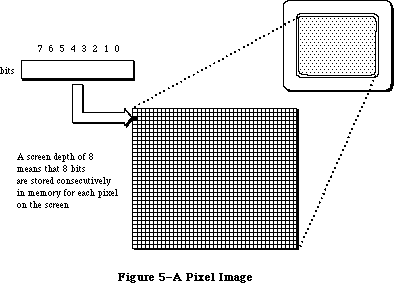 Figure 5–A Pixel Image
_______________________________________________________________________________
»Pixel Patterns
With Color QuickDraw, monochrome patterns are replaced by a new form of pattern structure, the pixel pattern, which offers greater flexibility in the use of color. The three pattern fields in a grafPort—pnPat, bkPat, and fillPat—have been replaced by the pnPixPat, bkPixPat, and fillPixPat fields in a cGrafPort. The format for a pixel pattern is shown below:
TYPE
PixPatHandle = ^PixPatPtr;
PixPatPtr = ^PixPat;
PixPat = RECORD
patType: INTEGER; {pattern type}
patMap: PixMapHandle; {pattern characteristics}
patData: Handle; {pixel image defining }
{ pattern}
patXData: Handle; {expanded pixel image}
patXValid: INTEGER; {flags for expanded }
{ pattern data}
patXMap: Handle; {handle to expanded }
{ pattern data}
pat1Data: Pattern; {old-style pattern/RGB }
{ color}
END;
Field descriptions
patType The patType field specifies the pattern’s type. The possible
values include: 0 = old-style pattern, 1 = full-color pixel
pattern, 2 = RGB pattern.
patMap The patMap field is a handle to the pixel map describing the
pattern’s pixel image.
patData The patData field is a handle to the pattern’s pixel image.
patXData The patXData field is a handle to an expanded pixel image used
internally by Color QuickDraw.
patXValid When the pattern’s data or color table change, you can
invalidate the expanded data by setting the patXValid field to –1.
patXMap The patXMap field is a handle that is reserved for use by Color
QuickDraw.
pat1Data The pat1Data field contains an old-style 8-by-8 pattern to be
used when this pattern is drawn into old grafPort. NewPixPat
sets this field to 50% gray.
Old-style patterns are still supported. When used in a cGrafPort, the QuickDraw routines PenPat and BackPat store the pattern within pnPixPat and bkPixPat, respectively, and set the patType to 0 to indicate that the structure contains old pattern data. Such patterns are limited to the original 8-by-8 dimensions and are always drawn using the values in the cGrafPort’s rgbFgColor and rgbBkColor fields. Similarly, filled drawing operations, such as FillRect, are also supported.
In a pixel pattern (patType = 1), the pattern’s dimensions, depth, resolution
(only 72 pixels per inch is supported), set of colors, and other characteristics are defined by a pixel map, referenced by the patMap handle. Since the pixel map has its own color table, pixel patterns can consist of any number of colors, and don’t usually use the foreground and background colors. The section on relative patterns, below, describes an exception to this rule.
Furthermore, patType = 1 patterns are not limited to a fixed size: their height and width can be any power of 2, as specified by the height and width of
patMap^^.bounds. (Notice that a pattern eight bits wide—the original QuickDraw size—has a row width of just one byte, contrary to the usual rule that the rowBytes field must be even.) This pattern type is generally read into memory using the GetPixPat routine, or set using the PenPixPat or BackPixPat routines.
Although the patMap defines the pattern’s characteristics, its baseAddr field is ignored; for a type1 pattern, the actual pixel image defining the pattern is stored in the handle in the pattern’s patData field. The pattern’s depth need not match that of the pixel map it’s painted into; the depth will be adjusted automatically when the pattern is drawn. Color QuickDraw maintains a private copy of the pattern’s pixel image, expanded to the current screen depth, and aligned to the current grafPort or cGrafPort, in the patXData field.
The third pattern type is RGBPat (patType = 2). Using the MakeRGBPat routine, the application can specify the exact color it wants to use. QuickDraw selects a pattern to approximate that color. In this way, an application can effectively increase the color resolution of the screen. Pixel patterns are particularly useful for dithering: mixing existing colors together to create the illusion of a third color that’s unavailable on a particular device. The MakeRGBPat routine aids in this process by constructing a dithered pattern to approximate a given absolute color. (See the description of MakeRGBPat in the
“Color QuickDraw Routines” section for more details.) In the current implementation of Color QuickDraw, an RGBPat can display 125 different patterns on a 4-bit-deep screen, or 2197 different patterns on an 8-bit-deep screen.
For an RGBPat, the RGB defines the image; there is no image data. An RGBPat has an 8-by-8, 2-bit-deep pattern.
A program that creates a pixMap must initialize the pixMap’s color table to describe the pixels. GetCTable could be used to read such a table from a resource file; you could then dispose of the pixMap’s color table and replace it with the one returned by GetCTable.
»Relative Patterns
Type1 pixel patterns contain color tables that describe the colors they use. Generally such a color table contains one entry for each color used in the pattern. For instance, if your pattern has five colors in it, you would probably create a four-bit-per-pixel pattern that uses pixel values 0–4, and a color table with five entries, numbered 0–4, that contain the RGB specifications for those pixel values.
When the pattern is drawn, each possible pixel value that isn’t specified in the color table is assigned a color. The largest unassigned pixel value becomes the foreground color; the smallest unassigned pixel value is assigned the background color. Remaining unassigned pixel values are given colors that are evenly distributed between the foreground and background.
For instance, in the color table mentioned above, pixel values 5–15 are unused. Assume that the foreground color is black and the background color is white. Pixel value 15 is assigned the foreground color, black; pixel value 5 is assigned the background color, white; the nine pixel values between them are assigned evenly distributed shades of gray. If the pixMap’s color table is set to NIL, all pixel values are determined by blending the foreground and background colors.
_______________________________________________________________________________
»Transfer Modes
A transfer mode is a method of placing information on the display devices. It involves an interaction between what your application is drawing (the source) and what’s already there (the destination). The original QuickDraw offered eight basic transfer modes:
• completely replacing the destination with the source (Copy), and its
inverse (NotCopy)
• combining the destination with the source (Or), and its inverse (NotOr)
• selectively clearing the destination with the source (Bic, for “bit
clear”), and its inverse (NotBic)
• selectively inverting the destination with the source (Xor), and its
inverse (NotXor)
This is how color affects these eight transfer modes when the source pixels are either black (all 1’s) or white (all 0’s):
Copy The Copy mode applies the foreground color to the black part of
the source (the part containing 1’s) and the background color to
the white part of the source (the part containing 0’s), and
replaces the destination with the colored source.
NotCopy The NotCopy mode applies the foreground color to the white part
of the source and the background color to the black part of the
source, and replaces the destination with the colored source. It
thus has the effect of reversing the foreground and background
colors.
Or The Or mode applies the foreground color to the black part of the
source and replaces the destination with the colored source. The
white part of the source isn’t transferred to the destination. If
the foreground is black, the drawing will be faster.
NotOr The NotOr mode applies the foreground color to the white part of
the source and replaces the destination with the colored source.
The black part of the source isn’t transferred to the destination.
If the foreground is black, the drawing will be faster.
Bic The Bic mode applies the background color to the black part of
the source and replaces the destination with the colored source.
The white part of the source isn’t transferred to the destination.
NotBic The NotBic mode applies the background color to the white part
of the source and replaces the destination with the colored source.
The black part of the source isn’t transferred to the destination.
Xor The Xor mode complements the bits in the destination corresponding
to the bits equal to 1 in the source. When used on a colored
destination, the color of the inverted destination isn’t defined.
NotXor The NotXor mode inverts the bits that are 0 in the source. When
used on a colored destination, the color of the inverted
destination isn’t defined.
Pixels of colors other than black and white aren’t all 1’s or all 0’s, so the application of a foreground color or a background color to the pixel produces an undefined result. For this reason, and because a pixPat already contains color, the foreground and background colors are ignored when your application is drawing with a pixPat. When your program draws a pixMap the foreground and background colors are not ignored. Make sure that the foreground is black and the background is white before you call CopyBits or the result will be undefined.
If you intend to draw with pixMaps or pixPats, you will probably want to use the Copy mode or one of the arithmetic modes described in the following section.
To help make color work well on different screen depths, Color QuickDraw does some validity checking of the foreground and background colors. If your application is drawing to a cGrafPort with a depth equal to 1 or 2, and if the RGB values of the foreground and background colors aren’t the same, but both of them map to the same pixel value, then the foreground color is inverted. This ensures that, for instance, red text drawn on a green background doesn’t map to black on black.
_______________________________________________________________________________
»Arithmetic Drawing Modes
Color QuickDraw uses a set of arithmetic drawing modes designed specifically for use with color. These modes change the destination pixels by performing arithmetic operations on the source and destination pixels. These drawing modes are most useful in 8-bit color, but work on 4-bit and 2-bit color as well. If the destination bitmap is one bit deep, the mode reverts to one of the old transfer modes that approximates the arithmetic mode requested.
Each drawing routine converts the source and destination pixels to their RGB components, performs an operation on each pair of components to provide a new RGB value for the destination, and then assigns the destination a pixel value close to the calculated RGB value. The arithmetic modes listed below can be used for all drawing operations; your application can pass them as a parameter to TextMode, PenMode, or CopyBits.
addOver This mode assigns to the destination pixel the color closest to
the sum of the source and destination RGB values. If the sum of
any of the RGB components exceeds the maximum allowable value,
65,535, the RGB value wraps around to the value less 65,536.
AddOver is slightly faster than addPin. If the destination bitmap
is one bit deep, addOver reverts to Xor.
addPin This mode assigns to the destination pixel the color closest to
the sum of the destination RGB values, pinned to a maximum allowable
RGB value. For grafPorts, the pin value is always white. For
cGrafPorts, the pin value is assigned using OpColor. If the
destination bitmap is one bit deep, addPin reverts to Bic.
subOver This mode assigns to the destination pixel the color closest to
the difference of the source and destination RGB values. If the
result is less than 0, the RGB value wraps around to 65,536 less
the result. SubOver is slightly faster than subPin. If the
destination bitmap is one bit deep, subOver reverts to Xor.
subPin This mode assigns to the destination pixel the color closest to
the difference of the sum and the destination RGB values, pinned
to a minimum allowable RGB value. For grafPorts, the pin value is
always black. In a cGrafPort, the pin value is assigned by using
OpColor. If the destination bitmap is one bit deep, subPin reverts
to Or.
adMax (Arithmetic Drawing Max) This mode compares the source and
destination pixels, and replaces the destination pixel with the
color containing the greater saturation of each of the RGB
components. Each RGB component comparison is done independently,
so the resulting color isn’t necessarily either the source or the
destination color. If the destination bitmap is one bit deep,
adMax reverts to Bic.
adMin (Arithmetic Drawing Min) This mode compares the source and
destination pixels, and replaces the destination pixel with
the color containing the lesser saturation of each of the RGB
components. Each RGB component is compared independently, so
the resulting color isn’t necessarily the source or the
destination color. If the destination bitmap is one bit deep,
adMin reverts to Or.
blend This mode replaces the destination pixel with a weighted average
of the colors of the source and destination pixels. The formula
used to calculate the destination is:
dest = source*weight/65,536 + destination*(1-weight/65,536)
where weight is an unsigned value between 1 and 65,535. In a
grafPort, the weight is set to 50% gray, so that equal weights
of the source and destination RGB components are combined to
produce the destination color. In a cGrafPort, the weight is an
RGBColor that individually specifies the weights of the red,
green, and blue components. The weight is assigned using OpColor.
If the destination bitmap is one bit deep, blend reverts to Copy.
Because drawing with the arithmetic modes uses the closest matching pixel values, and not necessarily exact matches, these modes might not produce the results you expect. For instance, suppose srcCopy mode is used to paint a green pixel on the screen in 4-bit mode. Of the 16 colors available, the closest green may contain a small amount of red, as in RGB components of 300 red, 65,535 green, and 0 blue. AddOver is then used to paint a red pixel on top of the green pixel, ideally resulting in a yellow pixel. The red pixel’s RGB components are 65,535 red, 0 green, and 0 blue. Adding the red components together wraps to 300, since the largest representable value is 65,535. In this case, AddOver would cause no visible change at all. Using AddPin with an opColor of white would produce the desired results.
On the Macintosh II the rules for setting the pen mode and the text mode have been relaxed slightly. It’s no longer necessary to specify a pattern mode or a source mode (patCopy as opposed to srcCopy) to perform a particular operation. QuickDraw will choose the correct drawing mode automatically. However, to be compatible with earlier versions of QuickDraw, you application must specify the correct drawing mode. Text and bitmaps should always use a source mode; rectangles, regions, polygons, arcs, ovals, round rectangles, and lines should always use a pattern mode.
The constants used for the arithmetic transfer modes are as follows:
CONST
blend = 32;
addPin = 33;
addOver = 34;
subPin = 35;
adMax = 37;
subOver = 38;
adMin = 39;
Warning: Unlike the rest of QuickDraw, the arithmetic modes don’t call the
Color Manager when mapping a requested RGB value to a pixel value.
If your application replaces the color matching routines, you must
either not use these modes, or you must maintain the inverse table
using the Color Manager routines.
_______________________________________________________________________________
»Replace with Transparency
The transparent mode replaces the destination pixel with the source pixel if the source pixel isn’t equal to the background color. This mode is most useful in 8-bit, 4-bit, or 2-bit color modes. To specify a transparent pattern, use the drawing mode transparent+patCopy. If the destination pixMap is one bit deep, the mode is translated to Or. Transparency can be specified as a parameter to TextMode, PenMode, or CopyBits.
Transparent mode is optimized to handle source bitmaps with large transparent holes, as an alternative to specifying an unusual clipping region or mask parameter to CopyMask. Patterns aren’t optimized, and may not draw as quickly.
The constant used for transparent mode is
CONST
transparent = 36;
_______________________________________________________________________________
»The Hilite Mode
This new method of highlighting exchanges the background color and the highlight color in the destination. This has the visual effect of using a highlighting pen to select the object. For instance, TextEdit uses the hilite mode to select text: if the highlight color is yellow, selected text appears on a yellow background. In general, highlighting should be used in place of inversion when selecting and deselecting objects such as text or graphics.
There are two ways to use hilite mode. The easiest is to call
BitClr (Ptr(HiliteMode,pHiliteBit));
just before calling InvertRect, InvertRgn, InvertArc, InvertRoundRct, or InvertPoly or any drawing using srcXor mode. On a one-bit-deep destination, this will work exactly like inversion, and is compatible with all versions of QuickDraw. Color QuickDraw resets the hilite bit after performing each drawing operation, so the hilite bit should be cleared immediately before calling a routine that is to do highlighting. Routines that formerly used Xor inversion, such as the Invert routines, Paint, Frame, LineTo, text drawing, and CopyBits, will now use hilite mode if the hilite bit is clear.
Assembly language note: You can use
BCLR #hiliteBit, hiliteMode
Do not alter the other bits in HiliteMode.
The second way to use hilite mode is to pass it directly to TextMode, PenMode, or CopyBits as a parameter.
Hilite mode uses the source or pattern to decide which bits to exchange; only bits that are on in the source or pattern can be highlighted in the destination.
A very small inversion should probably not use hilite mode, because a small selection in the hilite color might be too hard to see. TextEdit, for instance, uses hilite mode to select and deselect text, but not to blink the insertion point.
Hilite mode is optimized to look for consecutive pixels in either the hilite or background colors. For example, if the source is an all black pattern, the highlighting will be especially fast, operating internally on a long word at a time instead of a pixel at a time. Highlighting a large area without such consecutive pixels (a gray pattern, for instance) can be slow.
The global variable HiliteRGB is read from parameter RAM when the machine starts. Old grafPorts use the RGB values in the global HiliteRGB as the highlight color. Color grafPorts default to the global HiliteRGB, but can be overridden by the HiliteColor procedure.
The constants used with hilite mode are listed below:
CONST
hilite = 50;
pHiliteBit = 0; {this is the correct value for use when calling }
{ the BitClear trap. BClr must use the assembly }
{ language equate hiliteBit}
_______________________________________________________________________________
»THE COLOR CURSOR
_______________________________________________________________________________
Color QuickDraw supports the use of color cursors. The size of a cursor is still 16-by-16 pixels. The new CCrsr data structure is substantially different from the Cursor data structure used with the original QuickDraw: the CCrsr fields crsr1Data, crsrMask, and crsrHotSpot are the only fields that have counterparts in the Cursor record.
The structure of the color cursor is as follows:
TYPE
CCrsrHandle = ^CCrsrPtr;
CCrsrPtr = ^CCrsr;
CCrsr = RECORD
crsrType: INTEGER; {type of cursor}
crsrMap: PixMapHandle; {the cursor's pixmap}
crsrData: Handle; {cursor's data}
crsrXData: Handle; {expanded cursor data}
crsrXValid: INTEGER; {depth of expanded data}
crsrXHandle: Handle; {Reserved for future }
{ use}
crsr1Data: Bits16; {one-bit cursor}
crsrMask: Bits16; {cursor's mask}
crsrHotSpot: Point; {cursor's hotspot}
crsrXTable: LONGINT; {private}
crsrID: LONGINT; {ctSeed for expanded }
{ cursor}
END;
You will not normally need to manipulate the fields of a color cursor. Your application can load in a color cursor using the GetCCursor routine, and display it using the SetCCursor routine. When the application is finished using a color cursor, it should dispose of it using the DisposCCursor routine. These routines are discussed below in the section “Color QuickDraw Routines”.
Color cursors are stored in resources of type 'crsr'. The format of the 'crsr' resource is given in the section “Color QuickDraw Resource Formats”.
Field descriptions
crsrType The crsrType field specifies the type of cursor. Possible
values are: $8000 = old cursor, $8001 = new cursor.
crsrMap The crsrMap field is a handle to the pixel map defining the
cursor’s characteristics.
crsrData The crsrData field is a handle to the cursor’s pixel data.
crsrXData The crsrXData field is a handle to the expanded pixel image
used internally by Color QuickDraw (private).
crsrXValid The crsrXValid field contains the depth of the expanded cursor
image. If you change the cursor’s data or color table, you
should set this field to 0 to cause the cursor to be reexpanded.
You should never set it to any other values.
crsrXHandle The crsrXHandle field is reserved for future use.
crsr1Data The crsr1Data field contains a 16-by-16 one-bit image to be
displayed when the cursor is on 1-bit or 2-bit per pixel screens.
crsrMask The crsrMask field contains the cursor’s mask data. The same
1-bit-deep mask is used with crsrData and crsr1Data.
crsrHotSpot The crsrHotSpot field contains the cursor’s hot spot.
crsrXTable The crsrXTable field is reserved for future use.
crsrID The crsrID field contains the ctSeed for the cursor.
The first four fields of the CCrsr record are similar to the first four fields of the PixPat record, and are used in the same manner by Color QuickDraw. See the discussion of the patMap field under the section titled “Pixel Patterns” for more information on how the crsrMap is used.
The display of a cursor involves a relationship between a mask, stored in the crsrMask field with the same format used for old cursor masks, and an image. There are two possible sources for a color cursor’s image. When the cursor is on a screen whose depth is one or two bits per pixel, the image for the cursor is taken from Crsr1Data, which contains old-style cursor data. In this case, the relationship between data and mask is exactly as before. When the screen depth is greater than two bits per pixel, the image for the cursor is taken from crsrMap and crsrData; the relationship between mask and data is described in the following paragraph.
The data pixels within the mask replace the destination pixels. The data pixels outside the mask are displayed using an XOR with the destination pixels. If data pixels outside the mask are 0 (white), the destination pixels aren’t changed. If data pixels outside the mask are all 1’s (black), the destination pixels are complemented. All other values outside of the mask cause unpredictable results.
To work properly, a color cursor’s image should contain white pixels
(R = G = B = $FFFF) for the transparent part of the image, and black pixels
(R = G = B = $0000) for the inverting part of the image, in addition to the other colors in the cursor’s image. Thus, to define a cursor that contains two colors, it’s necessary to use a 2-bit-per-pixel cursor image (that is, a four-color image).
If your application changes the value of your cursor data or its color table, it should set the crsrXValid field to 0 to indicate that the cursor’s data needs to be reexpanded, and assign a new unique value to crsrID (unique values can be obtained using the GetCTSeed routine); then it should call SetCCursor to display the changed cursor.
_______________________________________________________________________________
»COLOR ICONS
_______________________________________________________________________________
A new data structure, known as CIcon, supports the use of color icons. The structure of the color icon is as follows:
TYPE
CIconHandle = ^CIconPtr;
CIconPtr = ^CIcon;
CIcon = RECORD
iconPMap: PixMap; {the icon's pixMap}
iconMask: BitMap; {the icon's mask bitmap}
iconBMap: BitMap; {the icon's bitMap}
iconData: Handle; {the icon's data}
iconMaskData: ARRAY[0..0] OF INTEGER;
{icon's mask and bitmap }
{ data}
END;
You won’t normally need to manipulate the fields of color icons. Your application can load a color icon into memory using the routine GetCIcon. To draw a color icon that’s already in memory, use PlotCIcon. When your application is through with a color icon, it can dispose of it using the DisposCIcon routine. These routines are discussed below in the section “Color QuickDraw Routines”.
Color icons are stored in a resource file as resource type 'cicn'. The format of the 'cicn' resource is given in the section “Using Color QuickDraw
Resources”.
Field descriptions
iconPMap The iconPMap field contains the pixel map describing the
icon. Note that pixMap is inline, not a handle.
iconMask The iconMask field contains a bit map for the icon’s mask.
iconBMap The iconBMap field contains a bit map for the icon.
iconData The iconData field contains a handle to the icon’s pixel image.
iconMaskData The iconMaskData field is an array containing the icon’s mask
data followed by the icon’s bitmap data. This is only used
when the icon is stored as a resource.
You can use color icons in menus in the same way that you could use old icons in menus. The menu definition procedure first tries to load in a 'cicn' with the specified resource ID. If it doesn’t find one, then it tries to load in an
'ICON' with that ID. The Dialog Manager will also use a 'cicn' in place of an
'ICON' if there is one with the ID specified in the item list. For more information, see the Menu Manager and Dialog Manager chapters.
_______________________________________________________________________________
»USING COLOR QUICKDRAW
_______________________________________________________________________________
This section gives an overview of routines that you will typically call while using Color QuickDraw. All routines are discussed below in the section “Color QuickDraw Routines”.
Using a color graphics port is much like using an old-style grafPort. The old routines SetPort and GetPort operate on grafPorts or cGrafPorts, and the global variable ThePort points to either to a grafPort or a cGrafPort. Color QuickDraw examines the two high bits of the portBits.rowBytes field (the portVersion field in a cGrafPort). If these bits equal 0, then it is a grafPort; if they are both 1, then it is a cGrafPort. In Pascal, use type coercion to convert between GrafPtr and cGrafPtr. For example:
VAR myPort: CGrafPtr;
SetPort (GrafPtr(myPort));
There’s still a graphics pen for line drawing, with a current size, location, pattern, and transfer mode; all of the old line- and shape-drawing operations, such as Move, LineTo, FrameRect, and PaintPoly, still work just as before. However, colors should be set with the new routines RGBForeColor and RGBBackColor (described below) instead of the old ForeColor and BackColor routines. If your application is using the Palette Manager, use the routines PMForeColor and PMBackColor instead.
PenPat and BackPat are still supported, and will construct a pixel pattern equivalent to the specified bit pattern. The patType field of this pattern is set to 0; thus it will always use the port’s current foreground and background colors at the time of drawing.
To read a multicolored pattern from a resource file, use the GetPixPat routine. Set these patterns using PenPixPat and BackPixPat, or pass them as parameters to Color QuickDraw’s color fill routines (such as FillCRect). These patterns have their own color tables and are generally not affected by the port’s foreground and background colors (refer to the earlier discussion of relative patterns).
Most routines that accept bitMaps as parameters also accept pixMaps (not PixMapHandles). Likewise, any new routine that has a pixMap as a parameter will also accept a bitMap. This allows one set of routines to work for all operations on images; the high bit of the rowBytes field distinguishes whether the parameter is a bitMap or a pixMap.
It’s worth noting here that resources are used slightly differently by Color QuickDraw than they were used by QuickDraw. For instance, with old QuickDraw, your application could call GetCursor before each SetCursor; the same handle would be passed back to the application each time. With Color QuickDraw, the color cursor is a compound structure, more complex than a simple resource handle. Color QuickDraw reads the requested resource, copies it, and then alters the copy before passing it to the application. Each time your application calls GetCCursor, it gets a new copy of the cursor. This means that your program should only call GetCCursor once, even if it does multiple SetCCursor calls. The new resource types should be marked as purgeable if you are concerned about memory space. This discussion holds true for color cursor, color pattern, color icon, and color table resources.
_______________________________________________________________________________
»COLOR QUICKDRAW ROUTINES
_______________________________________________________________________________
Color QuickDraw continues to support all the original QuickDraw calls described in the QuickDraw chapter. The following sections describe in detail the new Color QuickDraw routines, as well as changes to existing routines.
_______________________________________________________________________________
»Operations on CGrafPorts
PROCEDURE OpenCPort (port: CGrafPtr);
The OpenCPort procedure is analogous to OpenPort, except it opens a cGrafPort instead of a grafPort. You will rarely need to use this call, since OpenCPort is called by NewCWindow and GetNewCWindow, as well as by the Dialog Manager when the appropriate color resources are present. OpenCPort allocates storage for all the structures in the cGrafPort, and then calls InitCPort to initialize them. The new structures allocated are the portPixMap, the pnPixPat, the fillPixPat, the bkPixPat, and the grafVars handle. The GrafVars record structure is shown below:
TYPE
GrafVars = RECORD
rgbOpColor: RGBColor; {color for addPin, subPin, and }
{ blend}
rgbHiliteColor: RGBColor; {color for highlighting}
pmFgColor: Handle; {Palette handle for foreground }
{ color}
pmFgIndex: INTEGER; {index value for foreground}
pmBkColor: Handle; {Palette handle for background }
{ color}
pmBkIndex: INTEGER; {index value for background}
pmFlags: INTEGER; {Flags for Palette Manager}
END;
The rgbOpColor field is initialized as black, and the rgbHiliteColor field is initialized as the default HiliteRGB. All the rest of the GrafVars fields are initially zero.
The portPixMap is not allocated a color table of its own. When InitCPort is called, the handle to the current device’s color table is copied into the portPixMap.
PROCEDURE InitCPort (port: CGrafPtr);
The InitCPort procedure does not allocate any storage. It merely initializes all the fields in the cGrafPort to their default values. All old fields are initialized to the same values as a grafPort’s fields. New fields are given the following values:
portPixMap: copied from theGDevice^^.GDPMap
portVersion: $C000
grafVars: opColor initialized to black, rgbHiliteColor
initialized as default HiliteRGB. All other
fields are initialized as 0.
chExtra: 0
pnLocHFrac: 1/2
bkPixPat: white
rgbFgColor: black
rgbBkColor: white
pnPixPat: black
fillPixPat: black
The default portPixMap is set to be the same as the current device’s pixMap. This allows you to create an offscreen port that is identical to the screen’s grafPort or cGrafPort for drawing offscreen. If you want to use a different set of colors for offscreen drawing, you should create a new gDevice, and set it as the current gDevice before opening the cGrafPort. Refer to the section on offscreen bitMaps in the Graphics Devices chapter for more details.
As mentioned above, InitCPort does not copy the data from the current device’s color table to the portPixMap’s color table. It simply replaces whatever is in the pmTable field with a copy of the handle to the current device’s color table.
If you try to initialize a grafPort using InitCPort, it will simply return without doing anything.
PROCEDURE CloseCPort (port: CGrafPtr);
CloseCPort releases the memory allocated to the cGrafPort. It disposes of the visRgn, the clipRgn, the bkPixPat, the pnPixPat, the fillPixPat, and the grafVars handle. It also disposes of the portPixMap, but doesn’t dispose of the portPixMap’s color table (which is really owned by the gDevice). If you have placed your own color table into the portPixMap, either dispose of it before calling CloseCPort, or store another reference to it for other uses.
_______________________________________________________________________________
»Setting the Foreground and Background Colors
PROCEDURE RGBForeColor (color : RGBColor);
PROCEDURE RGBBackColor (color : RGBColor);
These two calls set the foreground and background colors to the best available match for the current device. The only drawing operations that aren’t affected by these colors are PlotCIcon, and drawing using the new color patterns. Before you call CopyBits with a pixMap as the source, you should set the foreground to black and the background to white.
If the current port is a cGrafPort, the specified RGB is placed in the rgbFgColor or rgbBkColor field (and the pixel value most closely matching that color is placed in the fgColor or bkColor field). If the current port is a grafPort, fgColor or bkColor is set to the old QuickDraw color determined by taking the high bit of each of the R, G, and B components, and using that three-bit number to select one of the eight QuickDraw colors. The ordering of the QuickDraw colors is shown in the GetForeColor description.
PROCEDURE GetForeColor (VAR color : RGBColor);
PROCEDURE GetBackColor (VAR color : RGBColor);
These two calls return the RGB components of the foreground and background colors set in the current port. The calls work for both grafPorts and cGrafPorts. If the current port is a cGrafPort, the returned value is taken directly from the rgbFgColor or rgbBkColor field. If the current port is a grafPort, then only eight possible RGB values can be returned. These eight values are determined by the values in a global variable named QDColors, which is a pointer to a color table containing the current QuickDraw colors.
The colors are stored in the following order:
Value Color Red Green Blue
0 black $0000 $0000 $0000
1 yellow $FC00 $F37D $052F
2 magenta $F2D7 $0856 $84EC
3 red $DD6B $08C2 $06A2
4 cyan $0241 $AB54 $EAFF
5 green $0000 $8000 $11B0
6 blue $0000 $0000 $D400
7 white $FFFF $FFFF $FFFF
This is the set of colors that Color QuickDraw uses to determine precisely what colors should be displayed by an old grafPort that is using color. The default set of colors has been adjusted to match the colors produced on the ImageWriter II printer.
_______________________________________________________________________________
»Color Drawing Operations
PROCEDURE FillCRect (r: Rect; ppat: PixPatHandle);
PROCEDURE FillCOval (r: Rect; ppat: PixPatHandle);
PROCEDURE FillCRoundRect (r: Rect; ovWd,ovHt: INTEGER; ppat: PixPatHandle);
PROCEDURE FillCArc (r: Rect; startAngle,arcAngle: INTEGER; ppat: PixPatHandle);
PROCEDURE FillCRgn (rgn: RgnHandle; ppat: PixPatHandle);
PROCEDURE FillCPoly (poly: PolyHandle; ppat: PixPatHandle);
These calls are analogous to their similarly named counterparts in QuickDraw. They allow a multicolored pattern to be used for filling.
PROCEDURE GetCPixel (h,v: INTEGER; VAR cPix: RGBColor);
The GetCPixel function returns the RGB of the pixel at the specified position in the current port.
PROCEDURE SetCPixel (h,v: INTEGER; cPix: RGBColor);
The SetCPixel function sets the pixel at the specified position to the pixel value that most closely matches the specified RGB.
_______________________________________________________________________________
»Creating Pixel Maps
FUNCTION NewPixMap : PixMapHandle;
The NewPixMap function creates a new, initialized pixMap data structure and returns a handle to it. All fields of the pixMap are copied from the current device’s pixMap except the color table. A handle to the color table is allocated but not initialized.
PROCEDURE DisposPixMap (pm: PixMapHandle);
The DisposPixMap procedure releases all storage allocated by NewPixMap. It disposes of the pixMap’s color table, and of the pixMap itself. Be careful not to dispose of a pixMap whose color table is the same as the current device’s color table.
PROCEDURE CopyPixMap (srcPM,dstPM: PixMapHandle);
The CopyPixMap routine is used for duplicating the pixMap data structure. CopyPixMap copies the contents of the source pixMap data structure to the destination pixMap data structure. The contents of the color table are copied, so the destination pixMap has its own copy of the color table. Since the baseAddr field of the pixMap is a pointer, the pointer, but not the image itself, is copied.
_______________________________________________________________________________
»Operations on Pixel Maps
PROCEDURE CopyBits (srcBits,dstBits: BitMap; srcRect, dstRect: Rect;
mode: INTEGER; maskRgn: RgnHandle);
CopyBits now accepts either bitMaps or pixMaps as parameters. For convenience, just as you could pass the current port^.portBits as a parameter to CopyBits, you can now pass GrafPtr(cPort)^.portBits. (Recall that in a cGrafPort the high two bits of the portVersion field are set. This field, in the same position in the port as portBits.rowBytes, indicates to QuickDraw that it has been passed a portPixMap handle.)
This call transfers an image from one bitMap or pixMap to another bitMap or pixMap. The source and destination may be of different depths, of different sizes, and they may have different color tables. Note, however, that the destination pixMap is assumed to use the same color table as the gDevice.
(This is because an inverse table is required for translation to the destination’s color table.)
During a CopyBits call, the foreground and background colors are applied to the image. To avoid unwanted coloring of the image, set the foreground to black and the background to white before calling this routine.
PROCEDURE CopyMask (srcBits,maskBits,dstBits: BitMap;
srcRect,maskRect,dstRect: Rect);
CopyMask is a new version of the CopyBits procedure, introduced in the Macintosh Plus. It transfers an image from the source to the destination only where the corresponding bit of the mask equals 1. The Macintosh II version will accept either a bitMap or pixMap as the srcBits or dstBits parameters. The maskBits parameter must be a bitMap.
Like the Macintosh Plus version, CopyMask doesn’t send any of its drawing commands through grafProc routines; thus CopyMask calls are not recorded in pictures. Unlike the Macintosh Plus version, the Macintosh II version of CopyMask is able to stretch the source and mask to fit the dstRect. The srcRect and maskRect should be the same size. CopyMask uses the same low-level code as CopyBits, so all the same rules regarding depth translation and color table translation apply.
During a CopyMask call, the foreground and background colors are applied to the image. To avoid unwanted coloring, set the foreground to black and the background to white before calling this routine.
PROCEDURE SeedCFill (srcBits, dstBits: BitMap; srcRect, dstRect: Rect;
seedH, seedV: INTEGER; matchProc: ProcPtr;
matchData: LONGINT);
The SeedCFill procedure generates a mask for use with CopyMask or CopyBits, with bits equal to 1 only in those positions where paint can leak from the starting seed point, like the MacPaint® bucket tool.
Given a rectangle within a source bitMap or pixMap (srcBits), SeedCFill returns a mask (dstBits) that contains 1’s in place of all pixels to which paint can leak from the specified seed position (seedH, seedV), expressed in the local coordinate system of the source pixMap. By default, paint can leak to all adjacent pixels whose RGB value exactly match that of the seed. To use this default, set matchProc and matchData to zero.
In generating the mask, SeedCFill performs CopyBits to convert srcBits to a
one-bit mask. It installs a default searchProc into the gDevice that returns 0 if the RGB value matches that of the seed; all other RGB values return 1’s.
If you want to customize SeedCFill, your application can specify a matchProc that is used instead of the default searchProc. It should return 0’s for RGB values that you want to be filled, and 1’s for values that shouldn’t be filled. When the matchProc is called, the GDRefCon field of the current gDevice contains a pointer to a record having the following structure:
MatchRec = RECORD
red: INTEGER;
green: INTEGER;
blue: INTEGER;
matchData: LONGINT
END;
In this record the red, green, and blue fields are the RGB of the pixel at the specified seed location. MatchData is simply whatever value you passed to SeedCFill as a parameter. For instance, your application could pass a handle to a color table whose entries should all be filled, and then, in the matchProc, check to see if the specified RGB matches any of the colors in the table.
No automatic scaling is performed: the source and destination rectangles must be the same size. Calls to SeedCFill are not clipped to the current port and are not stored into QuickDraw pictures.
PROCEDURE CalcCMask (srcBits, dstBits: BitMap; srcRect, dstRect: Rect;
seedRGB: RGBColor; matchProc: ProcPtr; matchData: LONGINT);
This routine generates a mask (dstBits) corresponding to the area in a pixMap
(srcBits) to which paint cannot leak from outside of the srcRect. The size of srcRect must be the same as the size of dstRect. By default, paint can leak to all adjacent pixels whose RGB values don’t match that of the seedRGB. To use this default, set matchProc and matchData to 0.
For instance, if srcBits contains a blue rectangle on a red background, and your application calls CalcCMask with the seedRGB equal to blue, then the returned mask has ones in the positions corresponding to the edges and interior of the rectangle, and zeros outside of the rectangle.
If you want to customize CalcCMask, your application can specify a matchProc that is used instead of the default searchProc. It should return 1’s for RGB values that define the edges of the mask, and 0’s for values that don’t.
When the matchProc is called, the GDRefCon field of the gDevice contains a pointer to a MatchRec record (the structure shown in the SeedCFill description). The red, green, and blue fields are the RGB of the pixel at the specifed seed location. MatchData is simply whatever value your application passed to CalcCMask as a parameter. For instance, your program could pass a handle to a color table whose entries should all be within the mask, and then, in the matchProc, check to see if the specified RGB matches any of the colors in the table.
No automatic scaling is performed: the source and destination rectangles must be the same size. Calls to CalcCMask are not clipped to the current port and are not stored into QuickDraw pictures.
_______________________________________________________________________________
»Operations on Pixel Patterns
FUNCTION NewPixPat: PixPatHandle;
The NewPixPat function creates a new pixPat data structure, and returns a handle to it. It calls NewPixMap to allocate and initialize the pattern’s pixMap to the same settings as theGDevice^^.GDPMap, and it sets the type of the pixPat to be a color pattern. The pat1Data field is initialized to a 50% gray pattern. New handles for data, expanded data, expanded map, and color table are allocated but not initialized. Including the pixPat itself, it allocates a total of six handles. You will generally not need to use this routine since the GetPixPat routine can be used to read in a pattern from a resource file.
The sizes of the pixMap and pixPat handles are the size of their respective data structures (see the type declarations in the “Summary” section). The other three handles are initially small in size. Once the pattern is drawn, the size of the expanded data is proportional to the size of the pattern data, but adjusted to the depth of the screen. The color table size is the size of the record structure plus eight bytes times the number of colors in the table.
»Creating a PixPat
To create a color pattern, use NewPixPat to allocate a new PixPatHandle. Set the rowBytes, bounds, and pixelSize of the pattern’s pixMap to the dimensions of the desired pattern. The rowBytes should be equal to (width of bounds)*pixelSize/8; it need not be even. The width and height of the bounds must be a power of two. Each scanline of the pattern must be at least one byte in length—that is, (width of bounds)*pixelSize must be at least eight. Set the other fields in the pattern’s pixMap as described in the section on the pixMap data structure.
Your application can explicitly specify the color corresponding to each pixel value with the color table. The color table for the pattern must be placed in the pmTable in the pixPat’s pixMap. Patterns may also contain colors that are relative to the foreground and background at the time that they are drawn. Refer to the section on the pixPat data structure for more information on relative patterns.
PROCEDURE DisposPixPat (ppat: PixPatHandle);
The DisposPixPat procedure releases all storage allocated by NewPixPat. It disposes of the pixPat’s data handle, expanded data handle, and pixMap handle.
PROCEDURE CopyPixPat (srcPP,dstPP: PixPatHandle);
The CopyPixPat procedure copies the contents of the source pixPat to the destination pixPat. It entirely copies all fields in the source pixPat, including the contents of the data handle, expanded data handle, expanded map, pixMap handle, and color table.
FUNCTION GetPixPat (patID: INTEGER): PixPatHandle;
The GetPixPat call creates a new pixPat data structure, and then uses the information in the resource of type 'ppat' and the specified ID to initialize the pixPat. The 'ppat' resource format is described in the section “Color QuickDraw Resource Formats”. If the resource with the specified ID is not found, then this routine returns a NIL handle.
PROCEDURE MakeRGBPat (ppat: PixPatHandle; myColor: RGBColor);
The MakeRGBPat procedure is a new call which generates a pixPat that approximates the specified color when drawn. For example, if your application is drawing to a device that has 4 bits per pixel, you will only get 16 colors if you simply set the foreground color and draw. If you use MakeRGBPat to select a pattern, and then draw using that pattern, you will effectively get 125 different colors. More colors are theoretically possible; this implementation opted for a fast pattern selection rather than the best possible pattern selection. If the device has 8 bits per pixel, you will effectively get 2197 colors.
Note that these patterns aren’t usually solid; they provide a wide selection of colors by alternating between colors with up to four colors in a pattern. For this reason lines that are one pixel wide may not look good using these patterns. For an RGB pattern, the patMap^^.bounds always contains (0, 0, 8, 8), and the patMap^^.rowbytes equals 2. Figure 6 shows how these colors are arranged.
When MakeRGBPat creates a color table, it only fills in the last colorSpec field: the other colorSpec values are computed at the time the drawing actually takes place, using the current pixel depth for the system.
Value RGB
0 computed RGB color
1 computed RGB color
2 computed RGB color
3 computed RGB color
4 RGBColor passed to MakeRGBPat routine
Figure 5–A Pixel Image
_______________________________________________________________________________
»Pixel Patterns
With Color QuickDraw, monochrome patterns are replaced by a new form of pattern structure, the pixel pattern, which offers greater flexibility in the use of color. The three pattern fields in a grafPort—pnPat, bkPat, and fillPat—have been replaced by the pnPixPat, bkPixPat, and fillPixPat fields in a cGrafPort. The format for a pixel pattern is shown below:
TYPE
PixPatHandle = ^PixPatPtr;
PixPatPtr = ^PixPat;
PixPat = RECORD
patType: INTEGER; {pattern type}
patMap: PixMapHandle; {pattern characteristics}
patData: Handle; {pixel image defining }
{ pattern}
patXData: Handle; {expanded pixel image}
patXValid: INTEGER; {flags for expanded }
{ pattern data}
patXMap: Handle; {handle to expanded }
{ pattern data}
pat1Data: Pattern; {old-style pattern/RGB }
{ color}
END;
Field descriptions
patType The patType field specifies the pattern’s type. The possible
values include: 0 = old-style pattern, 1 = full-color pixel
pattern, 2 = RGB pattern.
patMap The patMap field is a handle to the pixel map describing the
pattern’s pixel image.
patData The patData field is a handle to the pattern’s pixel image.
patXData The patXData field is a handle to an expanded pixel image used
internally by Color QuickDraw.
patXValid When the pattern’s data or color table change, you can
invalidate the expanded data by setting the patXValid field to –1.
patXMap The patXMap field is a handle that is reserved for use by Color
QuickDraw.
pat1Data The pat1Data field contains an old-style 8-by-8 pattern to be
used when this pattern is drawn into old grafPort. NewPixPat
sets this field to 50% gray.
Old-style patterns are still supported. When used in a cGrafPort, the QuickDraw routines PenPat and BackPat store the pattern within pnPixPat and bkPixPat, respectively, and set the patType to 0 to indicate that the structure contains old pattern data. Such patterns are limited to the original 8-by-8 dimensions and are always drawn using the values in the cGrafPort’s rgbFgColor and rgbBkColor fields. Similarly, filled drawing operations, such as FillRect, are also supported.
In a pixel pattern (patType = 1), the pattern’s dimensions, depth, resolution
(only 72 pixels per inch is supported), set of colors, and other characteristics are defined by a pixel map, referenced by the patMap handle. Since the pixel map has its own color table, pixel patterns can consist of any number of colors, and don’t usually use the foreground and background colors. The section on relative patterns, below, describes an exception to this rule.
Furthermore, patType = 1 patterns are not limited to a fixed size: their height and width can be any power of 2, as specified by the height and width of
patMap^^.bounds. (Notice that a pattern eight bits wide—the original QuickDraw size—has a row width of just one byte, contrary to the usual rule that the rowBytes field must be even.) This pattern type is generally read into memory using the GetPixPat routine, or set using the PenPixPat or BackPixPat routines.
Although the patMap defines the pattern’s characteristics, its baseAddr field is ignored; for a type1 pattern, the actual pixel image defining the pattern is stored in the handle in the pattern’s patData field. The pattern’s depth need not match that of the pixel map it’s painted into; the depth will be adjusted automatically when the pattern is drawn. Color QuickDraw maintains a private copy of the pattern’s pixel image, expanded to the current screen depth, and aligned to the current grafPort or cGrafPort, in the patXData field.
The third pattern type is RGBPat (patType = 2). Using the MakeRGBPat routine, the application can specify the exact color it wants to use. QuickDraw selects a pattern to approximate that color. In this way, an application can effectively increase the color resolution of the screen. Pixel patterns are particularly useful for dithering: mixing existing colors together to create the illusion of a third color that’s unavailable on a particular device. The MakeRGBPat routine aids in this process by constructing a dithered pattern to approximate a given absolute color. (See the description of MakeRGBPat in the
“Color QuickDraw Routines” section for more details.) In the current implementation of Color QuickDraw, an RGBPat can display 125 different patterns on a 4-bit-deep screen, or 2197 different patterns on an 8-bit-deep screen.
For an RGBPat, the RGB defines the image; there is no image data. An RGBPat has an 8-by-8, 2-bit-deep pattern.
A program that creates a pixMap must initialize the pixMap’s color table to describe the pixels. GetCTable could be used to read such a table from a resource file; you could then dispose of the pixMap’s color table and replace it with the one returned by GetCTable.
»Relative Patterns
Type1 pixel patterns contain color tables that describe the colors they use. Generally such a color table contains one entry for each color used in the pattern. For instance, if your pattern has five colors in it, you would probably create a four-bit-per-pixel pattern that uses pixel values 0–4, and a color table with five entries, numbered 0–4, that contain the RGB specifications for those pixel values.
When the pattern is drawn, each possible pixel value that isn’t specified in the color table is assigned a color. The largest unassigned pixel value becomes the foreground color; the smallest unassigned pixel value is assigned the background color. Remaining unassigned pixel values are given colors that are evenly distributed between the foreground and background.
For instance, in the color table mentioned above, pixel values 5–15 are unused. Assume that the foreground color is black and the background color is white. Pixel value 15 is assigned the foreground color, black; pixel value 5 is assigned the background color, white; the nine pixel values between them are assigned evenly distributed shades of gray. If the pixMap’s color table is set to NIL, all pixel values are determined by blending the foreground and background colors.
_______________________________________________________________________________
»Transfer Modes
A transfer mode is a method of placing information on the display devices. It involves an interaction between what your application is drawing (the source) and what’s already there (the destination). The original QuickDraw offered eight basic transfer modes:
• completely replacing the destination with the source (Copy), and its
inverse (NotCopy)
• combining the destination with the source (Or), and its inverse (NotOr)
• selectively clearing the destination with the source (Bic, for “bit
clear”), and its inverse (NotBic)
• selectively inverting the destination with the source (Xor), and its
inverse (NotXor)
This is how color affects these eight transfer modes when the source pixels are either black (all 1’s) or white (all 0’s):
Copy The Copy mode applies the foreground color to the black part of
the source (the part containing 1’s) and the background color to
the white part of the source (the part containing 0’s), and
replaces the destination with the colored source.
NotCopy The NotCopy mode applies the foreground color to the white part
of the source and the background color to the black part of the
source, and replaces the destination with the colored source. It
thus has the effect of reversing the foreground and background
colors.
Or The Or mode applies the foreground color to the black part of the
source and replaces the destination with the colored source. The
white part of the source isn’t transferred to the destination. If
the foreground is black, the drawing will be faster.
NotOr The NotOr mode applies the foreground color to the white part of
the source and replaces the destination with the colored source.
The black part of the source isn’t transferred to the destination.
If the foreground is black, the drawing will be faster.
Bic The Bic mode applies the background color to the black part of
the source and replaces the destination with the colored source.
The white part of the source isn’t transferred to the destination.
NotBic The NotBic mode applies the background color to the white part
of the source and replaces the destination with the colored source.
The black part of the source isn’t transferred to the destination.
Xor The Xor mode complements the bits in the destination corresponding
to the bits equal to 1 in the source. When used on a colored
destination, the color of the inverted destination isn’t defined.
NotXor The NotXor mode inverts the bits that are 0 in the source. When
used on a colored destination, the color of the inverted
destination isn’t defined.
Pixels of colors other than black and white aren’t all 1’s or all 0’s, so the application of a foreground color or a background color to the pixel produces an undefined result. For this reason, and because a pixPat already contains color, the foreground and background colors are ignored when your application is drawing with a pixPat. When your program draws a pixMap the foreground and background colors are not ignored. Make sure that the foreground is black and the background is white before you call CopyBits or the result will be undefined.
If you intend to draw with pixMaps or pixPats, you will probably want to use the Copy mode or one of the arithmetic modes described in the following section.
To help make color work well on different screen depths, Color QuickDraw does some validity checking of the foreground and background colors. If your application is drawing to a cGrafPort with a depth equal to 1 or 2, and if the RGB values of the foreground and background colors aren’t the same, but both of them map to the same pixel value, then the foreground color is inverted. This ensures that, for instance, red text drawn on a green background doesn’t map to black on black.
_______________________________________________________________________________
»Arithmetic Drawing Modes
Color QuickDraw uses a set of arithmetic drawing modes designed specifically for use with color. These modes change the destination pixels by performing arithmetic operations on the source and destination pixels. These drawing modes are most useful in 8-bit color, but work on 4-bit and 2-bit color as well. If the destination bitmap is one bit deep, the mode reverts to one of the old transfer modes that approximates the arithmetic mode requested.
Each drawing routine converts the source and destination pixels to their RGB components, performs an operation on each pair of components to provide a new RGB value for the destination, and then assigns the destination a pixel value close to the calculated RGB value. The arithmetic modes listed below can be used for all drawing operations; your application can pass them as a parameter to TextMode, PenMode, or CopyBits.
addOver This mode assigns to the destination pixel the color closest to
the sum of the source and destination RGB values. If the sum of
any of the RGB components exceeds the maximum allowable value,
65,535, the RGB value wraps around to the value less 65,536.
AddOver is slightly faster than addPin. If the destination bitmap
is one bit deep, addOver reverts to Xor.
addPin This mode assigns to the destination pixel the color closest to
the sum of the destination RGB values, pinned to a maximum allowable
RGB value. For grafPorts, the pin value is always white. For
cGrafPorts, the pin value is assigned using OpColor. If the
destination bitmap is one bit deep, addPin reverts to Bic.
subOver This mode assigns to the destination pixel the color closest to
the difference of the source and destination RGB values. If the
result is less than 0, the RGB value wraps around to 65,536 less
the result. SubOver is slightly faster than subPin. If the
destination bitmap is one bit deep, subOver reverts to Xor.
subPin This mode assigns to the destination pixel the color closest to
the difference of the sum and the destination RGB values, pinned
to a minimum allowable RGB value. For grafPorts, the pin value is
always black. In a cGrafPort, the pin value is assigned by using
OpColor. If the destination bitmap is one bit deep, subPin reverts
to Or.
adMax (Arithmetic Drawing Max) This mode compares the source and
destination pixels, and replaces the destination pixel with the
color containing the greater saturation of each of the RGB
components. Each RGB component comparison is done independently,
so the resulting color isn’t necessarily either the source or the
destination color. If the destination bitmap is one bit deep,
adMax reverts to Bic.
adMin (Arithmetic Drawing Min) This mode compares the source and
destination pixels, and replaces the destination pixel with
the color containing the lesser saturation of each of the RGB
components. Each RGB component is compared independently, so
the resulting color isn’t necessarily the source or the
destination color. If the destination bitmap is one bit deep,
adMin reverts to Or.
blend This mode replaces the destination pixel with a weighted average
of the colors of the source and destination pixels. The formula
used to calculate the destination is:
dest = source*weight/65,536 + destination*(1-weight/65,536)
where weight is an unsigned value between 1 and 65,535. In a
grafPort, the weight is set to 50% gray, so that equal weights
of the source and destination RGB components are combined to
produce the destination color. In a cGrafPort, the weight is an
RGBColor that individually specifies the weights of the red,
green, and blue components. The weight is assigned using OpColor.
If the destination bitmap is one bit deep, blend reverts to Copy.
Because drawing with the arithmetic modes uses the closest matching pixel values, and not necessarily exact matches, these modes might not produce the results you expect. For instance, suppose srcCopy mode is used to paint a green pixel on the screen in 4-bit mode. Of the 16 colors available, the closest green may contain a small amount of red, as in RGB components of 300 red, 65,535 green, and 0 blue. AddOver is then used to paint a red pixel on top of the green pixel, ideally resulting in a yellow pixel. The red pixel’s RGB components are 65,535 red, 0 green, and 0 blue. Adding the red components together wraps to 300, since the largest representable value is 65,535. In this case, AddOver would cause no visible change at all. Using AddPin with an opColor of white would produce the desired results.
On the Macintosh II the rules for setting the pen mode and the text mode have been relaxed slightly. It’s no longer necessary to specify a pattern mode or a source mode (patCopy as opposed to srcCopy) to perform a particular operation. QuickDraw will choose the correct drawing mode automatically. However, to be compatible with earlier versions of QuickDraw, you application must specify the correct drawing mode. Text and bitmaps should always use a source mode; rectangles, regions, polygons, arcs, ovals, round rectangles, and lines should always use a pattern mode.
The constants used for the arithmetic transfer modes are as follows:
CONST
blend = 32;
addPin = 33;
addOver = 34;
subPin = 35;
adMax = 37;
subOver = 38;
adMin = 39;
Warning: Unlike the rest of QuickDraw, the arithmetic modes don’t call the
Color Manager when mapping a requested RGB value to a pixel value.
If your application replaces the color matching routines, you must
either not use these modes, or you must maintain the inverse table
using the Color Manager routines.
_______________________________________________________________________________
»Replace with Transparency
The transparent mode replaces the destination pixel with the source pixel if the source pixel isn’t equal to the background color. This mode is most useful in 8-bit, 4-bit, or 2-bit color modes. To specify a transparent pattern, use the drawing mode transparent+patCopy. If the destination pixMap is one bit deep, the mode is translated to Or. Transparency can be specified as a parameter to TextMode, PenMode, or CopyBits.
Transparent mode is optimized to handle source bitmaps with large transparent holes, as an alternative to specifying an unusual clipping region or mask parameter to CopyMask. Patterns aren’t optimized, and may not draw as quickly.
The constant used for transparent mode is
CONST
transparent = 36;
_______________________________________________________________________________
»The Hilite Mode
This new method of highlighting exchanges the background color and the highlight color in the destination. This has the visual effect of using a highlighting pen to select the object. For instance, TextEdit uses the hilite mode to select text: if the highlight color is yellow, selected text appears on a yellow background. In general, highlighting should be used in place of inversion when selecting and deselecting objects such as text or graphics.
There are two ways to use hilite mode. The easiest is to call
BitClr (Ptr(HiliteMode,pHiliteBit));
just before calling InvertRect, InvertRgn, InvertArc, InvertRoundRct, or InvertPoly or any drawing using srcXor mode. On a one-bit-deep destination, this will work exactly like inversion, and is compatible with all versions of QuickDraw. Color QuickDraw resets the hilite bit after performing each drawing operation, so the hilite bit should be cleared immediately before calling a routine that is to do highlighting. Routines that formerly used Xor inversion, such as the Invert routines, Paint, Frame, LineTo, text drawing, and CopyBits, will now use hilite mode if the hilite bit is clear.
Assembly language note: You can use
BCLR #hiliteBit, hiliteMode
Do not alter the other bits in HiliteMode.
The second way to use hilite mode is to pass it directly to TextMode, PenMode, or CopyBits as a parameter.
Hilite mode uses the source or pattern to decide which bits to exchange; only bits that are on in the source or pattern can be highlighted in the destination.
A very small inversion should probably not use hilite mode, because a small selection in the hilite color might be too hard to see. TextEdit, for instance, uses hilite mode to select and deselect text, but not to blink the insertion point.
Hilite mode is optimized to look for consecutive pixels in either the hilite or background colors. For example, if the source is an all black pattern, the highlighting will be especially fast, operating internally on a long word at a time instead of a pixel at a time. Highlighting a large area without such consecutive pixels (a gray pattern, for instance) can be slow.
The global variable HiliteRGB is read from parameter RAM when the machine starts. Old grafPorts use the RGB values in the global HiliteRGB as the highlight color. Color grafPorts default to the global HiliteRGB, but can be overridden by the HiliteColor procedure.
The constants used with hilite mode are listed below:
CONST
hilite = 50;
pHiliteBit = 0; {this is the correct value for use when calling }
{ the BitClear trap. BClr must use the assembly }
{ language equate hiliteBit}
_______________________________________________________________________________
»THE COLOR CURSOR
_______________________________________________________________________________
Color QuickDraw supports the use of color cursors. The size of a cursor is still 16-by-16 pixels. The new CCrsr data structure is substantially different from the Cursor data structure used with the original QuickDraw: the CCrsr fields crsr1Data, crsrMask, and crsrHotSpot are the only fields that have counterparts in the Cursor record.
The structure of the color cursor is as follows:
TYPE
CCrsrHandle = ^CCrsrPtr;
CCrsrPtr = ^CCrsr;
CCrsr = RECORD
crsrType: INTEGER; {type of cursor}
crsrMap: PixMapHandle; {the cursor's pixmap}
crsrData: Handle; {cursor's data}
crsrXData: Handle; {expanded cursor data}
crsrXValid: INTEGER; {depth of expanded data}
crsrXHandle: Handle; {Reserved for future }
{ use}
crsr1Data: Bits16; {one-bit cursor}
crsrMask: Bits16; {cursor's mask}
crsrHotSpot: Point; {cursor's hotspot}
crsrXTable: LONGINT; {private}
crsrID: LONGINT; {ctSeed for expanded }
{ cursor}
END;
You will not normally need to manipulate the fields of a color cursor. Your application can load in a color cursor using the GetCCursor routine, and display it using the SetCCursor routine. When the application is finished using a color cursor, it should dispose of it using the DisposCCursor routine. These routines are discussed below in the section “Color QuickDraw Routines”.
Color cursors are stored in resources of type 'crsr'. The format of the 'crsr' resource is given in the section “Color QuickDraw Resource Formats”.
Field descriptions
crsrType The crsrType field specifies the type of cursor. Possible
values are: $8000 = old cursor, $8001 = new cursor.
crsrMap The crsrMap field is a handle to the pixel map defining the
cursor’s characteristics.
crsrData The crsrData field is a handle to the cursor’s pixel data.
crsrXData The crsrXData field is a handle to the expanded pixel image
used internally by Color QuickDraw (private).
crsrXValid The crsrXValid field contains the depth of the expanded cursor
image. If you change the cursor’s data or color table, you
should set this field to 0 to cause the cursor to be reexpanded.
You should never set it to any other values.
crsrXHandle The crsrXHandle field is reserved for future use.
crsr1Data The crsr1Data field contains a 16-by-16 one-bit image to be
displayed when the cursor is on 1-bit or 2-bit per pixel screens.
crsrMask The crsrMask field contains the cursor’s mask data. The same
1-bit-deep mask is used with crsrData and crsr1Data.
crsrHotSpot The crsrHotSpot field contains the cursor’s hot spot.
crsrXTable The crsrXTable field is reserved for future use.
crsrID The crsrID field contains the ctSeed for the cursor.
The first four fields of the CCrsr record are similar to the first four fields of the PixPat record, and are used in the same manner by Color QuickDraw. See the discussion of the patMap field under the section titled “Pixel Patterns” for more information on how the crsrMap is used.
The display of a cursor involves a relationship between a mask, stored in the crsrMask field with the same format used for old cursor masks, and an image. There are two possible sources for a color cursor’s image. When the cursor is on a screen whose depth is one or two bits per pixel, the image for the cursor is taken from Crsr1Data, which contains old-style cursor data. In this case, the relationship between data and mask is exactly as before. When the screen depth is greater than two bits per pixel, the image for the cursor is taken from crsrMap and crsrData; the relationship between mask and data is described in the following paragraph.
The data pixels within the mask replace the destination pixels. The data pixels outside the mask are displayed using an XOR with the destination pixels. If data pixels outside the mask are 0 (white), the destination pixels aren’t changed. If data pixels outside the mask are all 1’s (black), the destination pixels are complemented. All other values outside of the mask cause unpredictable results.
To work properly, a color cursor’s image should contain white pixels
(R = G = B = $FFFF) for the transparent part of the image, and black pixels
(R = G = B = $0000) for the inverting part of the image, in addition to the other colors in the cursor’s image. Thus, to define a cursor that contains two colors, it’s necessary to use a 2-bit-per-pixel cursor image (that is, a four-color image).
If your application changes the value of your cursor data or its color table, it should set the crsrXValid field to 0 to indicate that the cursor’s data needs to be reexpanded, and assign a new unique value to crsrID (unique values can be obtained using the GetCTSeed routine); then it should call SetCCursor to display the changed cursor.
_______________________________________________________________________________
»COLOR ICONS
_______________________________________________________________________________
A new data structure, known as CIcon, supports the use of color icons. The structure of the color icon is as follows:
TYPE
CIconHandle = ^CIconPtr;
CIconPtr = ^CIcon;
CIcon = RECORD
iconPMap: PixMap; {the icon's pixMap}
iconMask: BitMap; {the icon's mask bitmap}
iconBMap: BitMap; {the icon's bitMap}
iconData: Handle; {the icon's data}
iconMaskData: ARRAY[0..0] OF INTEGER;
{icon's mask and bitmap }
{ data}
END;
You won’t normally need to manipulate the fields of color icons. Your application can load a color icon into memory using the routine GetCIcon. To draw a color icon that’s already in memory, use PlotCIcon. When your application is through with a color icon, it can dispose of it using the DisposCIcon routine. These routines are discussed below in the section “Color QuickDraw Routines”.
Color icons are stored in a resource file as resource type 'cicn'. The format of the 'cicn' resource is given in the section “Using Color QuickDraw
Resources”.
Field descriptions
iconPMap The iconPMap field contains the pixel map describing the
icon. Note that pixMap is inline, not a handle.
iconMask The iconMask field contains a bit map for the icon’s mask.
iconBMap The iconBMap field contains a bit map for the icon.
iconData The iconData field contains a handle to the icon’s pixel image.
iconMaskData The iconMaskData field is an array containing the icon’s mask
data followed by the icon’s bitmap data. This is only used
when the icon is stored as a resource.
You can use color icons in menus in the same way that you could use old icons in menus. The menu definition procedure first tries to load in a 'cicn' with the specified resource ID. If it doesn’t find one, then it tries to load in an
'ICON' with that ID. The Dialog Manager will also use a 'cicn' in place of an
'ICON' if there is one with the ID specified in the item list. For more information, see the Menu Manager and Dialog Manager chapters.
_______________________________________________________________________________
»USING COLOR QUICKDRAW
_______________________________________________________________________________
This section gives an overview of routines that you will typically call while using Color QuickDraw. All routines are discussed below in the section “Color QuickDraw Routines”.
Using a color graphics port is much like using an old-style grafPort. The old routines SetPort and GetPort operate on grafPorts or cGrafPorts, and the global variable ThePort points to either to a grafPort or a cGrafPort. Color QuickDraw examines the two high bits of the portBits.rowBytes field (the portVersion field in a cGrafPort). If these bits equal 0, then it is a grafPort; if they are both 1, then it is a cGrafPort. In Pascal, use type coercion to convert between GrafPtr and cGrafPtr. For example:
VAR myPort: CGrafPtr;
SetPort (GrafPtr(myPort));
There’s still a graphics pen for line drawing, with a current size, location, pattern, and transfer mode; all of the old line- and shape-drawing operations, such as Move, LineTo, FrameRect, and PaintPoly, still work just as before. However, colors should be set with the new routines RGBForeColor and RGBBackColor (described below) instead of the old ForeColor and BackColor routines. If your application is using the Palette Manager, use the routines PMForeColor and PMBackColor instead.
PenPat and BackPat are still supported, and will construct a pixel pattern equivalent to the specified bit pattern. The patType field of this pattern is set to 0; thus it will always use the port’s current foreground and background colors at the time of drawing.
To read a multicolored pattern from a resource file, use the GetPixPat routine. Set these patterns using PenPixPat and BackPixPat, or pass them as parameters to Color QuickDraw’s color fill routines (such as FillCRect). These patterns have their own color tables and are generally not affected by the port’s foreground and background colors (refer to the earlier discussion of relative patterns).
Most routines that accept bitMaps as parameters also accept pixMaps (not PixMapHandles). Likewise, any new routine that has a pixMap as a parameter will also accept a bitMap. This allows one set of routines to work for all operations on images; the high bit of the rowBytes field distinguishes whether the parameter is a bitMap or a pixMap.
It’s worth noting here that resources are used slightly differently by Color QuickDraw than they were used by QuickDraw. For instance, with old QuickDraw, your application could call GetCursor before each SetCursor; the same handle would be passed back to the application each time. With Color QuickDraw, the color cursor is a compound structure, more complex than a simple resource handle. Color QuickDraw reads the requested resource, copies it, and then alters the copy before passing it to the application. Each time your application calls GetCCursor, it gets a new copy of the cursor. This means that your program should only call GetCCursor once, even if it does multiple SetCCursor calls. The new resource types should be marked as purgeable if you are concerned about memory space. This discussion holds true for color cursor, color pattern, color icon, and color table resources.
_______________________________________________________________________________
»COLOR QUICKDRAW ROUTINES
_______________________________________________________________________________
Color QuickDraw continues to support all the original QuickDraw calls described in the QuickDraw chapter. The following sections describe in detail the new Color QuickDraw routines, as well as changes to existing routines.
_______________________________________________________________________________
»Operations on CGrafPorts
PROCEDURE OpenCPort (port: CGrafPtr);
The OpenCPort procedure is analogous to OpenPort, except it opens a cGrafPort instead of a grafPort. You will rarely need to use this call, since OpenCPort is called by NewCWindow and GetNewCWindow, as well as by the Dialog Manager when the appropriate color resources are present. OpenCPort allocates storage for all the structures in the cGrafPort, and then calls InitCPort to initialize them. The new structures allocated are the portPixMap, the pnPixPat, the fillPixPat, the bkPixPat, and the grafVars handle. The GrafVars record structure is shown below:
TYPE
GrafVars = RECORD
rgbOpColor: RGBColor; {color for addPin, subPin, and }
{ blend}
rgbHiliteColor: RGBColor; {color for highlighting}
pmFgColor: Handle; {Palette handle for foreground }
{ color}
pmFgIndex: INTEGER; {index value for foreground}
pmBkColor: Handle; {Palette handle for background }
{ color}
pmBkIndex: INTEGER; {index value for background}
pmFlags: INTEGER; {Flags for Palette Manager}
END;
The rgbOpColor field is initialized as black, and the rgbHiliteColor field is initialized as the default HiliteRGB. All the rest of the GrafVars fields are initially zero.
The portPixMap is not allocated a color table of its own. When InitCPort is called, the handle to the current device’s color table is copied into the portPixMap.
PROCEDURE InitCPort (port: CGrafPtr);
The InitCPort procedure does not allocate any storage. It merely initializes all the fields in the cGrafPort to their default values. All old fields are initialized to the same values as a grafPort’s fields. New fields are given the following values:
portPixMap: copied from theGDevice^^.GDPMap
portVersion: $C000
grafVars: opColor initialized to black, rgbHiliteColor
initialized as default HiliteRGB. All other
fields are initialized as 0.
chExtra: 0
pnLocHFrac: 1/2
bkPixPat: white
rgbFgColor: black
rgbBkColor: white
pnPixPat: black
fillPixPat: black
The default portPixMap is set to be the same as the current device’s pixMap. This allows you to create an offscreen port that is identical to the screen’s grafPort or cGrafPort for drawing offscreen. If you want to use a different set of colors for offscreen drawing, you should create a new gDevice, and set it as the current gDevice before opening the cGrafPort. Refer to the section on offscreen bitMaps in the Graphics Devices chapter for more details.
As mentioned above, InitCPort does not copy the data from the current device’s color table to the portPixMap’s color table. It simply replaces whatever is in the pmTable field with a copy of the handle to the current device’s color table.
If you try to initialize a grafPort using InitCPort, it will simply return without doing anything.
PROCEDURE CloseCPort (port: CGrafPtr);
CloseCPort releases the memory allocated to the cGrafPort. It disposes of the visRgn, the clipRgn, the bkPixPat, the pnPixPat, the fillPixPat, and the grafVars handle. It also disposes of the portPixMap, but doesn’t dispose of the portPixMap’s color table (which is really owned by the gDevice). If you have placed your own color table into the portPixMap, either dispose of it before calling CloseCPort, or store another reference to it for other uses.
_______________________________________________________________________________
»Setting the Foreground and Background Colors
PROCEDURE RGBForeColor (color : RGBColor);
PROCEDURE RGBBackColor (color : RGBColor);
These two calls set the foreground and background colors to the best available match for the current device. The only drawing operations that aren’t affected by these colors are PlotCIcon, and drawing using the new color patterns. Before you call CopyBits with a pixMap as the source, you should set the foreground to black and the background to white.
If the current port is a cGrafPort, the specified RGB is placed in the rgbFgColor or rgbBkColor field (and the pixel value most closely matching that color is placed in the fgColor or bkColor field). If the current port is a grafPort, fgColor or bkColor is set to the old QuickDraw color determined by taking the high bit of each of the R, G, and B components, and using that three-bit number to select one of the eight QuickDraw colors. The ordering of the QuickDraw colors is shown in the GetForeColor description.
PROCEDURE GetForeColor (VAR color : RGBColor);
PROCEDURE GetBackColor (VAR color : RGBColor);
These two calls return the RGB components of the foreground and background colors set in the current port. The calls work for both grafPorts and cGrafPorts. If the current port is a cGrafPort, the returned value is taken directly from the rgbFgColor or rgbBkColor field. If the current port is a grafPort, then only eight possible RGB values can be returned. These eight values are determined by the values in a global variable named QDColors, which is a pointer to a color table containing the current QuickDraw colors.
The colors are stored in the following order:
Value Color Red Green Blue
0 black $0000 $0000 $0000
1 yellow $FC00 $F37D $052F
2 magenta $F2D7 $0856 $84EC
3 red $DD6B $08C2 $06A2
4 cyan $0241 $AB54 $EAFF
5 green $0000 $8000 $11B0
6 blue $0000 $0000 $D400
7 white $FFFF $FFFF $FFFF
This is the set of colors that Color QuickDraw uses to determine precisely what colors should be displayed by an old grafPort that is using color. The default set of colors has been adjusted to match the colors produced on the ImageWriter II printer.
_______________________________________________________________________________
»Color Drawing Operations
PROCEDURE FillCRect (r: Rect; ppat: PixPatHandle);
PROCEDURE FillCOval (r: Rect; ppat: PixPatHandle);
PROCEDURE FillCRoundRect (r: Rect; ovWd,ovHt: INTEGER; ppat: PixPatHandle);
PROCEDURE FillCArc (r: Rect; startAngle,arcAngle: INTEGER; ppat: PixPatHandle);
PROCEDURE FillCRgn (rgn: RgnHandle; ppat: PixPatHandle);
PROCEDURE FillCPoly (poly: PolyHandle; ppat: PixPatHandle);
These calls are analogous to their similarly named counterparts in QuickDraw. They allow a multicolored pattern to be used for filling.
PROCEDURE GetCPixel (h,v: INTEGER; VAR cPix: RGBColor);
The GetCPixel function returns the RGB of the pixel at the specified position in the current port.
PROCEDURE SetCPixel (h,v: INTEGER; cPix: RGBColor);
The SetCPixel function sets the pixel at the specified position to the pixel value that most closely matches the specified RGB.
_______________________________________________________________________________
»Creating Pixel Maps
FUNCTION NewPixMap : PixMapHandle;
The NewPixMap function creates a new, initialized pixMap data structure and returns a handle to it. All fields of the pixMap are copied from the current device’s pixMap except the color table. A handle to the color table is allocated but not initialized.
PROCEDURE DisposPixMap (pm: PixMapHandle);
The DisposPixMap procedure releases all storage allocated by NewPixMap. It disposes of the pixMap’s color table, and of the pixMap itself. Be careful not to dispose of a pixMap whose color table is the same as the current device’s color table.
PROCEDURE CopyPixMap (srcPM,dstPM: PixMapHandle);
The CopyPixMap routine is used for duplicating the pixMap data structure. CopyPixMap copies the contents of the source pixMap data structure to the destination pixMap data structure. The contents of the color table are copied, so the destination pixMap has its own copy of the color table. Since the baseAddr field of the pixMap is a pointer, the pointer, but not the image itself, is copied.
_______________________________________________________________________________
»Operations on Pixel Maps
PROCEDURE CopyBits (srcBits,dstBits: BitMap; srcRect, dstRect: Rect;
mode: INTEGER; maskRgn: RgnHandle);
CopyBits now accepts either bitMaps or pixMaps as parameters. For convenience, just as you could pass the current port^.portBits as a parameter to CopyBits, you can now pass GrafPtr(cPort)^.portBits. (Recall that in a cGrafPort the high two bits of the portVersion field are set. This field, in the same position in the port as portBits.rowBytes, indicates to QuickDraw that it has been passed a portPixMap handle.)
This call transfers an image from one bitMap or pixMap to another bitMap or pixMap. The source and destination may be of different depths, of different sizes, and they may have different color tables. Note, however, that the destination pixMap is assumed to use the same color table as the gDevice.
(This is because an inverse table is required for translation to the destination’s color table.)
During a CopyBits call, the foreground and background colors are applied to the image. To avoid unwanted coloring of the image, set the foreground to black and the background to white before calling this routine.
PROCEDURE CopyMask (srcBits,maskBits,dstBits: BitMap;
srcRect,maskRect,dstRect: Rect);
CopyMask is a new version of the CopyBits procedure, introduced in the Macintosh Plus. It transfers an image from the source to the destination only where the corresponding bit of the mask equals 1. The Macintosh II version will accept either a bitMap or pixMap as the srcBits or dstBits parameters. The maskBits parameter must be a bitMap.
Like the Macintosh Plus version, CopyMask doesn’t send any of its drawing commands through grafProc routines; thus CopyMask calls are not recorded in pictures. Unlike the Macintosh Plus version, the Macintosh II version of CopyMask is able to stretch the source and mask to fit the dstRect. The srcRect and maskRect should be the same size. CopyMask uses the same low-level code as CopyBits, so all the same rules regarding depth translation and color table translation apply.
During a CopyMask call, the foreground and background colors are applied to the image. To avoid unwanted coloring, set the foreground to black and the background to white before calling this routine.
PROCEDURE SeedCFill (srcBits, dstBits: BitMap; srcRect, dstRect: Rect;
seedH, seedV: INTEGER; matchProc: ProcPtr;
matchData: LONGINT);
The SeedCFill procedure generates a mask for use with CopyMask or CopyBits, with bits equal to 1 only in those positions where paint can leak from the starting seed point, like the MacPaint® bucket tool.
Given a rectangle within a source bitMap or pixMap (srcBits), SeedCFill returns a mask (dstBits) that contains 1’s in place of all pixels to which paint can leak from the specified seed position (seedH, seedV), expressed in the local coordinate system of the source pixMap. By default, paint can leak to all adjacent pixels whose RGB value exactly match that of the seed. To use this default, set matchProc and matchData to zero.
In generating the mask, SeedCFill performs CopyBits to convert srcBits to a
one-bit mask. It installs a default searchProc into the gDevice that returns 0 if the RGB value matches that of the seed; all other RGB values return 1’s.
If you want to customize SeedCFill, your application can specify a matchProc that is used instead of the default searchProc. It should return 0’s for RGB values that you want to be filled, and 1’s for values that shouldn’t be filled. When the matchProc is called, the GDRefCon field of the current gDevice contains a pointer to a record having the following structure:
MatchRec = RECORD
red: INTEGER;
green: INTEGER;
blue: INTEGER;
matchData: LONGINT
END;
In this record the red, green, and blue fields are the RGB of the pixel at the specified seed location. MatchData is simply whatever value you passed to SeedCFill as a parameter. For instance, your application could pass a handle to a color table whose entries should all be filled, and then, in the matchProc, check to see if the specified RGB matches any of the colors in the table.
No automatic scaling is performed: the source and destination rectangles must be the same size. Calls to SeedCFill are not clipped to the current port and are not stored into QuickDraw pictures.
PROCEDURE CalcCMask (srcBits, dstBits: BitMap; srcRect, dstRect: Rect;
seedRGB: RGBColor; matchProc: ProcPtr; matchData: LONGINT);
This routine generates a mask (dstBits) corresponding to the area in a pixMap
(srcBits) to which paint cannot leak from outside of the srcRect. The size of srcRect must be the same as the size of dstRect. By default, paint can leak to all adjacent pixels whose RGB values don’t match that of the seedRGB. To use this default, set matchProc and matchData to 0.
For instance, if srcBits contains a blue rectangle on a red background, and your application calls CalcCMask with the seedRGB equal to blue, then the returned mask has ones in the positions corresponding to the edges and interior of the rectangle, and zeros outside of the rectangle.
If you want to customize CalcCMask, your application can specify a matchProc that is used instead of the default searchProc. It should return 1’s for RGB values that define the edges of the mask, and 0’s for values that don’t.
When the matchProc is called, the GDRefCon field of the gDevice contains a pointer to a MatchRec record (the structure shown in the SeedCFill description). The red, green, and blue fields are the RGB of the pixel at the specifed seed location. MatchData is simply whatever value your application passed to CalcCMask as a parameter. For instance, your program could pass a handle to a color table whose entries should all be within the mask, and then, in the matchProc, check to see if the specified RGB matches any of the colors in the table.
No automatic scaling is performed: the source and destination rectangles must be the same size. Calls to CalcCMask are not clipped to the current port and are not stored into QuickDraw pictures.
_______________________________________________________________________________
»Operations on Pixel Patterns
FUNCTION NewPixPat: PixPatHandle;
The NewPixPat function creates a new pixPat data structure, and returns a handle to it. It calls NewPixMap to allocate and initialize the pattern’s pixMap to the same settings as theGDevice^^.GDPMap, and it sets the type of the pixPat to be a color pattern. The pat1Data field is initialized to a 50% gray pattern. New handles for data, expanded data, expanded map, and color table are allocated but not initialized. Including the pixPat itself, it allocates a total of six handles. You will generally not need to use this routine since the GetPixPat routine can be used to read in a pattern from a resource file.
The sizes of the pixMap and pixPat handles are the size of their respective data structures (see the type declarations in the “Summary” section). The other three handles are initially small in size. Once the pattern is drawn, the size of the expanded data is proportional to the size of the pattern data, but adjusted to the depth of the screen. The color table size is the size of the record structure plus eight bytes times the number of colors in the table.
»Creating a PixPat
To create a color pattern, use NewPixPat to allocate a new PixPatHandle. Set the rowBytes, bounds, and pixelSize of the pattern’s pixMap to the dimensions of the desired pattern. The rowBytes should be equal to (width of bounds)*pixelSize/8; it need not be even. The width and height of the bounds must be a power of two. Each scanline of the pattern must be at least one byte in length—that is, (width of bounds)*pixelSize must be at least eight. Set the other fields in the pattern’s pixMap as described in the section on the pixMap data structure.
Your application can explicitly specify the color corresponding to each pixel value with the color table. The color table for the pattern must be placed in the pmTable in the pixPat’s pixMap. Patterns may also contain colors that are relative to the foreground and background at the time that they are drawn. Refer to the section on the pixPat data structure for more information on relative patterns.
PROCEDURE DisposPixPat (ppat: PixPatHandle);
The DisposPixPat procedure releases all storage allocated by NewPixPat. It disposes of the pixPat’s data handle, expanded data handle, and pixMap handle.
PROCEDURE CopyPixPat (srcPP,dstPP: PixPatHandle);
The CopyPixPat procedure copies the contents of the source pixPat to the destination pixPat. It entirely copies all fields in the source pixPat, including the contents of the data handle, expanded data handle, expanded map, pixMap handle, and color table.
FUNCTION GetPixPat (patID: INTEGER): PixPatHandle;
The GetPixPat call creates a new pixPat data structure, and then uses the information in the resource of type 'ppat' and the specified ID to initialize the pixPat. The 'ppat' resource format is described in the section “Color QuickDraw Resource Formats”. If the resource with the specified ID is not found, then this routine returns a NIL handle.
PROCEDURE MakeRGBPat (ppat: PixPatHandle; myColor: RGBColor);
The MakeRGBPat procedure is a new call which generates a pixPat that approximates the specified color when drawn. For example, if your application is drawing to a device that has 4 bits per pixel, you will only get 16 colors if you simply set the foreground color and draw. If you use MakeRGBPat to select a pattern, and then draw using that pattern, you will effectively get 125 different colors. More colors are theoretically possible; this implementation opted for a fast pattern selection rather than the best possible pattern selection. If the device has 8 bits per pixel, you will effectively get 2197 colors.
Note that these patterns aren’t usually solid; they provide a wide selection of colors by alternating between colors with up to four colors in a pattern. For this reason lines that are one pixel wide may not look good using these patterns. For an RGB pattern, the patMap^^.bounds always contains (0, 0, 8, 8), and the patMap^^.rowbytes equals 2. Figure 6 shows how these colors are arranged.
When MakeRGBPat creates a color table, it only fills in the last colorSpec field: the other colorSpec values are computed at the time the drawing actually takes place, using the current pixel depth for the system.
Value RGB
0 computed RGB color
1 computed RGB color
2 computed RGB color
3 computed RGB color
4 RGBColor passed to MakeRGBPat routine
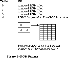 Figure 6–RGB Pattern
PROCEDURE PenPixPat (ppat: PixPatHandle);
PROCEDURE BackPixPat (ppat: PixPatHandle);
The PenPixPat and BackPixPat calls are analogous to PenPat and BackPat, but use multicolor pixel patterns instead of old-style patterns. If you try to use a pixel pattern in a grafPort, the data in the pat1Data field is placed into pnPat, bkPat, or fillPat.
When your application sets a pixel pattern, the handle you provide is actually placed into the grafPort or cGrafPort. In this way, QuickDraw can expand the pattern once (saving it in the patXData field) when the pattern is first set, and won’t have to reexpand it each time you set the pattern.
Since your handle is actually stored in the grafPort or cGrafPort, it’s considered bad form to dispose of a PixPatHandle that is currently set as the pnPixPat or bkPixPat. (Just in case you forget, QuickDraw will remove all references to your pattern from existing grafPorts or cGrafPorts when you dispose of it.)
Using the old calls PenPat and BackPat, you can still set old-style patterns in a cGrafPort. If necessary, it creates a new pixPatHandle in which to store the pattern (because, as described above, pixPatHandles are owned by the application). As in old grafPorts, old-style patterns are drawn using the foreground and background colors at the time of drawing, not at the time the pattern is set.
_______________________________________________________________________________
»Operations on Color Cursors
FUNCTION GetCCursor (crsrID: INTEGER): CCrsrHandle;
The GetCCursor call creates a new CCrsr data structure, then initializes it using the information in the resource of type 'crsr' with the specified ID. The 'crsr' resource format is described in the section “Color QuickDraw Resource Formats”. If the resource with the specified ID isn’t found, then this routine returns a NIL handle.
Since GetCCursor creates a new CCrsr data structure each time it is called, your application shouldn’t call GetCCursor before each call to SetCCursor
(unlike the way GetCursor/SetCursor were normally used). GetCCursor doesn’t dispose or detach the resource, so resources of type 'crsr' should typically be purgeable.
PROCEDURE SetCCursor (cCrsr: CCrsrHandle);
The SetCCursor procedure allows your application to set a multicolor cursor. At the time the cursor is set, it’s expanded to the current screen depth so that it can be drawn rapidly.
If your application has changed the cursor’s data or its color table, it must also invalidate the fields crsrXValid and crsrID (described in the section on the Color Cursor data structure), before calling SetCCursor.
PROCEDURE DisposCCursor(cCrsr: CCrsrHandle);
The DisposCCursor procedure disposes all structures allocated by GetCCursor.
PROCEDURE AllocCursor;
The AllocCursor procedure reallocates cursor memory. Under normal circumstances, you should never need to use this call, since reallocation of cursor memory is only necessary after the depth of one of the screens has been changed.
_______________________________________________________________________________
»Operations on Color Icons
FUNCTION GetCIcon(id: INTEGER): CIconHandle;
The GetCIcon function allocates a CIcon data structure and initializes it using the information in the resource of type 'cicn' with the specified ID. It returns the handle to the icon’s data structure. If the specified resource
isn’t found, a NIL handle is returned.
The format of the 'cicn' resource is described in the section “Color QuickDraw Resource Formats”.
Since GetCIcon creates a new CIcon data structure each time it is called, your application shouldn’t call GetCIcon before each call to PlotCIcon. GetCIcon doesn’t dispose or detach the resource, so resources of type 'cicn' should typically be purgeable.
PROCEDURE DisposCIcon(theIcon: CIconHandle);
The DisposCIcon procedure disposes all structures allocated by GetCIcon.
PROCEDURE PlotCIcon(theRect: Rect; theIcon: CIconHandle);
The PlotCIcon procedure draws the specified icon in the specified rectangle. The iconMask field of the CIcon determines which pixels of the iconPMap are drawn and which are not. Only pixels with 1’s in corresponding positions in the iconMask are drawn; all other pixels don’t affect the destination. If the screen depth is one or two bits per pixel, the iconBMap is used as the source instead of the iconPMap (unless the rowBytes field of iconBMap is 0, indicating that there is no iconBMap.
When the icon is drawn, the boundsRect of the iconPMap is used as the image’s source rectangle. The icon and its mask are both stretched to the destination rectangle. The icon’s pixels are remapped to the current depth and color table, if necessary. The bounds fields of the iconPMap, iconBMap, and iconMask are expected to be equal in size.
PlotCIcon is simply a structured call to CopyMask. As such, it doesn’t send any of its drawing commands through grafProc routines; thus, PlotCIcon calls are not recorded in pictures.
_______________________________________________________________________________
»Operations on CGrafPort Fields
PROCEDURE SetPortPix (pm: PixMapHandle);
The SetPortPix call is analogous to SetPortBits, and should be used instead of SetPortBits for cGrafPorts. It replaces the portPixMap field of the current cGrafPort with the specified handle. SetPortPix has no effect when used with an old grafPort. If SetPortBits is called when the current port is a cGrafPort, it does nothing.
PROCEDURE OpColor (color: RGBColor);
If the current port is a cGrafPort, the OpColor procedure sets the red, green, and blue values used by the AddPin, SubPin, and Blend drawing modes. This information is actually stored in the grafVars handle in the cGrafPort, but you should never need to reference it directly. If the current port is a grafPort, OpColor has no effect.
PROCEDURE HiliteColor (color:RGBColor);
The highlight color is used by all drawing operations that use the highlight transfer mode. When a cGrafPort is created, its highlight color is initialized from the global variable HiliteRGB. The HiliteColor procedure allows you to change the highlighting color used by the current port. This information is actually stored in the grafVars handle in the cGrafPort, but you should never need to reference it directly. If the current port is a grafPort, HiliteColor has no effect.
PROCEDURE CharExtra (extra:Fixed);
The CharExtra procedure sets the cGrafPort’s charExtra field, which specifies the number of pixels by which to widen every character excluding the space character in a line of text. The charExtra field is stored in a compressed format based on the txSize field, so you must set txSize before calling CharExtra. The initial charExtra setting is 0. CharExtra will accept a negative number. CharExtra has no effect on grafPorts.
PROCEDURE SetStdCProcs (VAR cProcs: CQDProcs);
This procedure sets all the fields of the given CQDProcs record to point to the standard low-level routines. You can then change the ones you wish to point to your own routines. For example, if your procedure that processes picture comments is named MyComments, you will store @MyComments in the commentProc field of the CQD Procs record.
When drawing in a cGrafPort, your application must always use SetStdCProcs instead of SetStdProcs.
_______________________________________________________________________________
»Operations on Color Tables
FUNCTION GetCTable (ctID: INTEGER): CTabHandle;
The GetCTable routine allocates a new color table data structure, and initializes it using the information in the resource of type 'clut' having the specified ID. If the specified resource is not found, a NIL handle is returned.
If you place this handle into a pixMap, you should first dispose of the handle that was already there.
The format of the 'clut' resource is given in the section “Color QuickDraw Resource Formats”. Resource ID values 0..127 are reserved for system use. Any
'clut' resources defined by your application should have IDs in the range
128..1023. This value must be in the ctSeed field in the resource, and will be placed in the ctSeed field of the color table (for color table identification). All other possible seed values are used to identify newly created color tables, and color tables that have been modified.
If you modify a color table, you should invalidate it by changing its ctSeed field. You can get a new unique value for ctSeed using the routine GetCTSeed, described in the Color Manager chapter.
PROCEDURE DisposCTable(cTable: CTabHandle);
The DisposCTable procedure disposes the handle allocated for a color table.
_______________________________________________________________________________
»COLOR QUICKDRAW RESOURCE FORMATS
_______________________________________________________________________________
Several new resource types have been defined for use with Color QuickDraw. They are
'crsr' Color cursor resource type
'ppat' Pixel Pattern resource type
'cicn' Color Icon resource type
'clut' Color Look-Up Table resource type
The precise formats of resources of these types are given below.
It is important to note that resources are used somewhat differently by Color QuickDraw. For instance, with old QuickDraw, you could do a GetCursor for each SetCursor, and the same handle would be passed back to the application each time. With Color QuickDraw, the color cursor, icon, and pattern are compound structures, more complex than a simple resource handle. Color QuickDraw reads the requested resource, copies it, and then alters the copy before passing it to the application. Each time you call GetCCursor, you get a new copy of the cursor. This means that you should do one GetCCursor call for a cursor, even if you do multiple SetCCursor calls. These new resource types should be marked as purgeable if you are concerned about memory space.
Here are the resource formats of the resources used by Color QuickDraw. All offsets are measured from the beginning of the resource’s data.
»'crsr' (Color Cursor)
CCrsr {data structure describing cursor}
crsrType: [2 bytes] = $8001
crsrMap: [4 bytes] = offset to pixMap structure
crsrData: [4 bytes] = offset to pixel data
crsrXData: [4 bytes] = 0
crsrXValid: [2 bytes] = 0
crsrXHandle: [4 bytes] = 0
crsr1Data: [32 bytes] = 1 bit image for cursor
crsrMask: [32 bytes] = cursor’s mask
crsrHotSpot: [4 bytes] = cursor’s hotSpot (v,h)
crsrXTable: [4 bytes] = 0
crsrID: [4 bytes] = 0
PixMap {pixMap describing cursor’s pixel image}
baseAddr: [4 bytes] = 0
rowBytes: [2 bytes] = rowBytes of image
bounds: [8 bytes] = boundary rectangle of image
pmVersion: [2 bytes] = 0
packType: [2 bytes] = 0
packSize: [4 bytes] = 0
hRes: [4 bytes] = $00480000
vRes: [4 bytes] = $00480000
pixelType: [2 bytes] = 0 = chunky
pixelSize: [2 bytes] = bits per pixel in image
cmpCount: [2 bytes] = 1
cmpSize: [2 bytes] = pixelsize
planeBytes: [4 bytes] = 0
pmTable: [4 bytes] = offset to color table data
pmReserved: [4 bytes] = 0
pixel data [see below] data for cursor
color table data [see below] data for color table
The crsrMap field of the CCrsr record contains an offset to the pixMap record from the beginning of the resource data. The crsrData field of the CCrsr record contains an offset to the pixel data from the beginning of the resource data. The pmTable field of the pixMap record contains an offset to the color table data from the beginning of the resource data. The size of the pixelData is calculated by subtracting the offset to the pixel data from the offset to the color table data. The color table data consists of a color table record
(ctSeed, ctFlags, ctSize) followed by ctSize+1 color table entries. Each entry in the color table connects a pixel value used in the pixel data to an actual RGB.
»'ppat' (Pixel Pattern)
PixPat record {data structure describing pattern}
patType [2 bytes] = 1 (full color pattern)
patMap [4 bytes] = offset to pixMap record
patData [4 bytes] = offset to pixel data
patXData [4 bytes] = 0
patXValid [2 bytes] = –1
patXMap [4 bytes] = 0
pat1Data [8 bytes] = 1 bit pattern data
PixMap { pixMap describing pattern’s pixel image }
baseAddr [4 bytes] = 0
rowBytes [2 bytes] = rowBytes of image
bounds [8 bytes] = boundary rectangle of image
pmVersion [2 bytes] = 0
packType [2 bytes] = 0
packSize [4 bytes] = 0
hRes [4 bytes] = $00480000
vRes [4 bytes] = $00480000
pixelType [2 bytes] = 0 = chunky
pixelSize [2 bytes] = bits per pixel in image
cmpCount [2 bytes] = 1
cmpSize [2 bytes] = pixelsize
planeBytes [4 bytes] = 0
pmTable [4 bytes] = offset to color table data
pmReserved [4 bytes] = 0
pixel data [see below] data for pattern
color table data [see below] data for color table
The patMap field of the pixPat record contains an offset to the pixMap record from the beginning of the resource data. The patData field of the pixPat record contains an offset to the pixel data from the beginning of the resource data. The pmTable field of the pixMap record contains an offset to the color table data from the beginning of the resource data. The size of the pixelData is calculated by subtracting the offset to the pixel data from the offset to the color table data. The color table data consists of a color table record
(ctSeed, ctFlags, ctSize) followed by ctSize+1 color table entries. Each entry in the color table connects a pixel value used in the pixel data to an actual RGB.
»'cicn' (Color Icon)
IconPMap {pixMap describing icon’s pixel image}
baseAddr [4 bytes] = 0
rowBytes [2 bytes] = rowBytes of image
bounds [8 bytes] = boundary rectangle of image
pmVersion [2 bytes] = 0
packType [2 bytes] = 0
packSize [4 bytes] = 0
hRes [4 bytes] = $00480000
vRes [4 bytes] = $00480000
pixelType [2 bytes] = 0 = chunky
pixelSize [2 bytes] = bits per pixel in image
cmpCount [2 bytes] = 1
cmpSize [2 bytes] = pixelsize
planeBytes [4 bytes] = 0
pmTable [4 bytes] = 0
pmReserved [4 bytes] = 0
IconMask {Mask used when drawing icon}
baseAddr [4 bytes] = 0
rowBytes [2 bytes] = rowBytes of image
bounds [8 bytes] = boundary rectangle of image
IconBMap {Image used when drawing to 1 bit screen}
baseAddr [4 bytes] = 0
rowBytes [2 bytes] = rowBytes of image
bounds [8 bytes] = boundary rectangle of image
IconData {placeholder for image’s handle}
[4 bytes] = 0
MaskData {the icon’s mask data }
[n bytes] n = IconMask.rowBytes*height
BMapData {the icon’s bitMap data }
[n bytes] n = IconBMap.rowBytes*height
PMapCTab {the icon’s color table }
[n bytes] n = 8+(ColorTable.ctSize+1)*CTEntrySize
PMapData {the icon’s image data }
[n bytes] n = IconPMap.rowBytes*height
In the calculations above:
height = IconPMap^^.bounds.bottom–IconPMap^^.bounds.top.
IconPMap is the pixMap describing the data in the IconData field. IconMask is the mask that is to be applied to the data when it is drawn. IconBMap is a bitMap to be drawn when the destination is only one or two pixels deep. If the rowbytes field of IconBMap is 0, then no data is loaded in for the IconBMap, and IconPMap is always used when drawing the icon. MaskData is the mask’s data. It is immediately followed by the bitMap’s data (which may be NIL). Next is the color table describing the IconPMap, as shown below. The final entry in the resource is the pixMap’s data.
»'clut' (Color Table)
ctSeed [4 bytes] = 0
ctFlags [2 bytes] = $0000 if pixMap color table
= $8000 if device color table
ctSize [2 bytes] = #entries – 1
table data [n bytes] n = 8*(ctSize+1)
The 'clut' resource format is an exact duplicate of a color table in memory. Each element in the table data is four integers (eight bytes): a value field followed by red, green, and blue values. If the color table is used to describe a pixMap, then ctFlags should be set to 0, and the value field of each entry contains the pixel value to be associated with the following RGB. If the color table is used to describe a device, then ctFlags should be set to $8000, and the value fields should be set to 0. In this case, the implicit values are based on each entry’s position in the table.
There are several default color tables that are in the Macintosh II ROMs. There is one for each of the standard pixel depths. The resource ID for each table is the same as the depth. For example, the default color table used when you switch your system to 8 bits per pixel mode is stored with resource ID = 8.
There is one other default color table. This color table defines the eight QuickDraw colors, the colors displayed by programs using the old QuickDraw model. This color table has ID = 127. Its values are given in the section
“Setting the Foreground and Background Colors”.
_______________________________________________________________________________
»USING TEXT WITH QUICKDRAW
_______________________________________________________________________________
This section explains those QuickDraw features which provide enhanced text handling for the Macintosh Plus, Macintosh SE, and Macintosh II. The drawing mode recommended for all applications is SrcOr, because it uses the least memory and will draw the entire character in all cases. The SrcOr mode will only affect other parts of existing characters if the characters overlap. In srcOr mode the color of the character is determined by the foreground color, although text drawing is fastest when the foreground color is black.
With QuickDraw, characters can kern to the left and to the right. QuickDraw begins drawing a series of characters at the specified pen position plus the kernMax field (part of the Font record), plus any kerning below the baseline caused by italicizing the font. (The kernMax field denotes the kerning allowed by a given font; since its value is normally negative, most fonts kern to the left. Italicizing also normally moves the pen to the left.) QuickDraw then draws through the ending pen position, plus any kerning above the baseline caused by italicizing the font (normally to the right), plus any space required to handle the outlined or shadowed part of the character.
To draw text in any mode, including the kerned part of the leading and trailing characters, it is best to draw the entire line of text at once. If the line must be drawn in pieces, it is best to end each piece with a space character, so that the succeeding piece can harmlessly kern left, and the last character drawn (a space) will not have any right kerning clipped.
Macintosh Plus and Macintosh SE Note: The Macintosh Plus and Macintosh SE
versions of QuickDraw clip a leading
left-kerning character, and do not take
italicizing into account when
positioning the pen. Also, it adds a
constant of 32 to the width of the
character imaging rectangle, causing
large italicized fonts to have the
rightmost character clipped in drawing
modes other than srcOr.
The outline and shadow styles cause the outline and shadow of the character to be drawn in the foreground color. The inside of the character, if drawn at all, is drawn in the background color. The center of shadowed or outlined text is drawn in a grafPort in scrBic mode if the text mode is srcOr, for compatibility with old applications. This allows black text with a white outline on an arbitrary background. If the text mode is srcBic, the center of shadowed or outlined text is drawn in srcOr.
The style underline draws the underline through the entire text line, from the pen starting position through the ending position, plus any offsets from font or italic kerning, as described above. If the underline is outlined or shadowed, the ends aren’t capped, that is, consecutively drawn pieces of text should maintain a continuous underline.
Macintosh Plus and Macintosh SE Note: QuickDraw clips the right edge of the
underline to the ending pen position,
causing outlined or shadowed underlines
to match imperfectly when text is drawn
in sections.
One of the reasons that SrcOr is recommended is that the maximum stack space required for a text font drawing operation can be considerable. Text drawing uses a minimum amount of stack if the mode is srcOr, the forecolor is black, the visRgn and clipRgn are rectangular (or at least the destination of the text is contained within a rectangular portion of the visRgn), the text is not scaled, and the text does not have to be italicized, boldfaced, outlined, or shadowed by QuickDraw. Otherwise, the amount of stack required to draw all of the text at once depends most on the size and width of the the text and the depth of the destination.
If QuickDraw can’t get enough stack space to draw an entire string at once, it will draw the string in pieces. This can produce disconcerting results in modes other than srcOr or srcBic if some of the characters overlap because of kerning or italicizing. If the mode is srcCopy, overlapping characters will be clipped by the last drawn character. If the mode is srcXor, pixels where the characters overlap are not drawn at all. If the mode is one of the arithmetic modes, the arithmetic rules are followed, ignoring that the destination may include part of the string being drawn.
The stack space required for a drawing operation on the Macintosh II is roughly given by this calculation:
(text width) * (text height) * (font depth) / (8 bits per byte ) + 3K
Font depth normally equals the screen depth. If the amount of stack space available is small (less than 3.5K), QuickDraw instead uses a font depth of 1, which is slow, but uses less stack space.
On the Macintosh Plus, the required stack space is roughly equal to
(text width) * (text height) / (8 bits per byte ) + 2K
_______________________________________________________________________________
»Text Mask Mode
For the Macintosh II, the maskConstant may be added to another drawing mode to cause just the character portion of the text to be applied in the current transfer mode to the destination. If the text font contains more than one color, or if the drawing mode is an arithmetic mode or hilite mode, the mask mode causes only the portion of the characters not equal to the background to be drawn.
The arithmetic drawing modes and hilite mode apply the character’s background to the destination; this can lead to undesirable results if the text is drawn in pieces. The leftmost part of a text piece is drawn on top of a previous text piece if the font kerns to the left. The maskMode supplied in addition to these modes causes only the foreground part of the character to be drawn. The only reasonable way to kern to the right in text mask mode is to use srcOr, or to add trailing characters. This is because the rightmost kern is clipped.
The constant used with maskMode is
CONST
mask = 64;
_______________________________________________________________________________
»Drawing with Multibit Fonts
Multibit fonts may have a specific color. The transfer modes may not produce the desired results with a multibit font. The arithmetic modes, transparent mode, and hilite mode work equally well with single bit and multibit fonts.
Unlike single bit fonts, multibit fonts draw quickly in srcOr only if the foreground is white. Single bit fonts draw quickly in srcOr only if the foreground is black. Grayscale fonts produce a spectrum of colors, rather than just the foreground and background colors.
_______________________________________________________________________________
»Fractional Character Positioning
CGrafPorts maintain the fractional horizontal pen position, so that a series of text drawing calls will accumulate the fractional position. The horizontal pen fraction is initially set to 1/2. InitPort, Move, MoveTo, Line and LineTo reset the pen position to 1/2. For an old grafPort, the pen fraction is hard-coded to 1/2.
_______________________________________________________________________________
»COLOR PICTURE FORMAT
_______________________________________________________________________________
With the introduction of the Macintosh II, the QuickDraw picture structure has been extended to include new color graphics opcodes. The new version 2 pictures and opcodes solve many of the major problems encountered by developers in using PICT files, and enable future expandibility. For example, it is now possible to specify the resolution of bitMap data. Color can also be specified, but only chunky pixels (contiguously stored pixel components) are currently recognized by Color QuickDraw. Your application only needs to generate or recognize the chunky pixel format. This format is indicated by an image or pixMap with a cmpCount = 1.
Most existing applications can use version 2 pictures without modification. On a Macintosh II, version 2 pictures will draw in color (if drawn directly to the screen). Currently, they will print using the old QuickDraw colors. Eventually, new print drivers will be able to take advantage of the new color information.
On a Macintosh 512K enhanced, Macintosh Plus, and Macintosh SE, a patch in the System file beginning with version 4.1 provides QuickDraw with the capability to convert and display version 2 pictures. The original Macintosh and Macintosh 512 can’t display version 2 pictures.
Applications that generate pictures in the QuickDraw picture format are free to use any or all available features to support their particular needs. Some will use only the imaging features. You may wish to include comments in the picture that are pertinent to the needs of your application. In general, put a minimal amount of information in your PICT files and avoid redundancy. It’s reasonable for receiving applications to ignore picture opcodes that aren’t needed.
_______________________________________________________________________________
»Differences Between Version 1 and Version 2 Pictures
The major differences between version 1 and version 2 pictures are listed below.
• Version 1 opcodes are a single byte; version 2 opcodes are 2 bytes in
length. This means that old opcodes in a version 2 picture take up two
bytes, not one.
• Version 1 data may start on byte boundaries; version 2 opcodes and data
are always word-aligned.
• In version 2, the high bit of the rowBytes field is used to indicate a
pixMap instead of a bitMap; pixData then replaces bitData.
• All unused version 2 opcodes, as well as the number of data bytes
associated with each, have been defined. This was done so that picture
parsing code can safely ignore unknown opcodes, enabling future use
of these opcodes in a backward-compatible manner.
_______________________________________________________________________________
»Drawing With Version 2 Pictures in Old GrafPorts
Enhancements to the DrawPicture routine allow pictures created with Color QuickDraw to be used in either a cGrafPort or an old-style grafPort. You can create a picture using the new drawing commands in a cGrafPort, cut it, and then paste it into an application that draws into an old grafPort. The picture will lose some of its detail when transferred in this way, but should be sufficient for most purposes. The following considerations apply to the use of this technique:
• The rgbFgColor and rbgBkColor fields are mapped to the old-style
Quickdraw constant (one of eight) that most closely approximates that
color. For a grafPort with depth greater than one, even old applications
will be able to draw color pictures.
• Patterns created using MakeRGBPat are drawn as old-style patterns having
approximately the same luminance as the original pattern.
• Other new patterns are replaced by the old-style pattern contained
in the pat1Data field of the PixPat data structure. This field is
initialized to 50% gray by the NewPixPat routine, and is initialized
from the resource in a GetPixPat call.
• PixMaps in the picture are drawn without interpretation. The CopyBits
call performs all necessary mapping to the destination screen. If
the picture is drawn on a Macintosh Plus or a Macintosh SE, or if the
BitsProc routine has been replaced by the application, the pixMap is
converted to a bitMap before it’s drawn.
• Changes to the ChExtra and pnLocHFrac fields, and the Hilite color
and OpColor, are ignored.
A new standard opcodeProc, SetStdCProc, is called by QuickDraw when it is playing back a color picture and it sees a new opcode that it doesn’t recognize. The default routine simply reads and ignores all undefined opcodes.
_______________________________________________________________________________
»Picture Representation
The PICT file is a data fork file with a 512-byte header, followed by a picture (see Figure 7). This data fork file contains a QuickDraw (and now, Color QuickDraw) data structure within which a graphic application, using standard QuickDraw calls, places drawing opcodes to represent an object or image graphic data. In the QuickDraw picture format, pictures consist of opcodes followed by picture data.
Figure 6–RGB Pattern
PROCEDURE PenPixPat (ppat: PixPatHandle);
PROCEDURE BackPixPat (ppat: PixPatHandle);
The PenPixPat and BackPixPat calls are analogous to PenPat and BackPat, but use multicolor pixel patterns instead of old-style patterns. If you try to use a pixel pattern in a grafPort, the data in the pat1Data field is placed into pnPat, bkPat, or fillPat.
When your application sets a pixel pattern, the handle you provide is actually placed into the grafPort or cGrafPort. In this way, QuickDraw can expand the pattern once (saving it in the patXData field) when the pattern is first set, and won’t have to reexpand it each time you set the pattern.
Since your handle is actually stored in the grafPort or cGrafPort, it’s considered bad form to dispose of a PixPatHandle that is currently set as the pnPixPat or bkPixPat. (Just in case you forget, QuickDraw will remove all references to your pattern from existing grafPorts or cGrafPorts when you dispose of it.)
Using the old calls PenPat and BackPat, you can still set old-style patterns in a cGrafPort. If necessary, it creates a new pixPatHandle in which to store the pattern (because, as described above, pixPatHandles are owned by the application). As in old grafPorts, old-style patterns are drawn using the foreground and background colors at the time of drawing, not at the time the pattern is set.
_______________________________________________________________________________
»Operations on Color Cursors
FUNCTION GetCCursor (crsrID: INTEGER): CCrsrHandle;
The GetCCursor call creates a new CCrsr data structure, then initializes it using the information in the resource of type 'crsr' with the specified ID. The 'crsr' resource format is described in the section “Color QuickDraw Resource Formats”. If the resource with the specified ID isn’t found, then this routine returns a NIL handle.
Since GetCCursor creates a new CCrsr data structure each time it is called, your application shouldn’t call GetCCursor before each call to SetCCursor
(unlike the way GetCursor/SetCursor were normally used). GetCCursor doesn’t dispose or detach the resource, so resources of type 'crsr' should typically be purgeable.
PROCEDURE SetCCursor (cCrsr: CCrsrHandle);
The SetCCursor procedure allows your application to set a multicolor cursor. At the time the cursor is set, it’s expanded to the current screen depth so that it can be drawn rapidly.
If your application has changed the cursor’s data or its color table, it must also invalidate the fields crsrXValid and crsrID (described in the section on the Color Cursor data structure), before calling SetCCursor.
PROCEDURE DisposCCursor(cCrsr: CCrsrHandle);
The DisposCCursor procedure disposes all structures allocated by GetCCursor.
PROCEDURE AllocCursor;
The AllocCursor procedure reallocates cursor memory. Under normal circumstances, you should never need to use this call, since reallocation of cursor memory is only necessary after the depth of one of the screens has been changed.
_______________________________________________________________________________
»Operations on Color Icons
FUNCTION GetCIcon(id: INTEGER): CIconHandle;
The GetCIcon function allocates a CIcon data structure and initializes it using the information in the resource of type 'cicn' with the specified ID. It returns the handle to the icon’s data structure. If the specified resource
isn’t found, a NIL handle is returned.
The format of the 'cicn' resource is described in the section “Color QuickDraw Resource Formats”.
Since GetCIcon creates a new CIcon data structure each time it is called, your application shouldn’t call GetCIcon before each call to PlotCIcon. GetCIcon doesn’t dispose or detach the resource, so resources of type 'cicn' should typically be purgeable.
PROCEDURE DisposCIcon(theIcon: CIconHandle);
The DisposCIcon procedure disposes all structures allocated by GetCIcon.
PROCEDURE PlotCIcon(theRect: Rect; theIcon: CIconHandle);
The PlotCIcon procedure draws the specified icon in the specified rectangle. The iconMask field of the CIcon determines which pixels of the iconPMap are drawn and which are not. Only pixels with 1’s in corresponding positions in the iconMask are drawn; all other pixels don’t affect the destination. If the screen depth is one or two bits per pixel, the iconBMap is used as the source instead of the iconPMap (unless the rowBytes field of iconBMap is 0, indicating that there is no iconBMap.
When the icon is drawn, the boundsRect of the iconPMap is used as the image’s source rectangle. The icon and its mask are both stretched to the destination rectangle. The icon’s pixels are remapped to the current depth and color table, if necessary. The bounds fields of the iconPMap, iconBMap, and iconMask are expected to be equal in size.
PlotCIcon is simply a structured call to CopyMask. As such, it doesn’t send any of its drawing commands through grafProc routines; thus, PlotCIcon calls are not recorded in pictures.
_______________________________________________________________________________
»Operations on CGrafPort Fields
PROCEDURE SetPortPix (pm: PixMapHandle);
The SetPortPix call is analogous to SetPortBits, and should be used instead of SetPortBits for cGrafPorts. It replaces the portPixMap field of the current cGrafPort with the specified handle. SetPortPix has no effect when used with an old grafPort. If SetPortBits is called when the current port is a cGrafPort, it does nothing.
PROCEDURE OpColor (color: RGBColor);
If the current port is a cGrafPort, the OpColor procedure sets the red, green, and blue values used by the AddPin, SubPin, and Blend drawing modes. This information is actually stored in the grafVars handle in the cGrafPort, but you should never need to reference it directly. If the current port is a grafPort, OpColor has no effect.
PROCEDURE HiliteColor (color:RGBColor);
The highlight color is used by all drawing operations that use the highlight transfer mode. When a cGrafPort is created, its highlight color is initialized from the global variable HiliteRGB. The HiliteColor procedure allows you to change the highlighting color used by the current port. This information is actually stored in the grafVars handle in the cGrafPort, but you should never need to reference it directly. If the current port is a grafPort, HiliteColor has no effect.
PROCEDURE CharExtra (extra:Fixed);
The CharExtra procedure sets the cGrafPort’s charExtra field, which specifies the number of pixels by which to widen every character excluding the space character in a line of text. The charExtra field is stored in a compressed format based on the txSize field, so you must set txSize before calling CharExtra. The initial charExtra setting is 0. CharExtra will accept a negative number. CharExtra has no effect on grafPorts.
PROCEDURE SetStdCProcs (VAR cProcs: CQDProcs);
This procedure sets all the fields of the given CQDProcs record to point to the standard low-level routines. You can then change the ones you wish to point to your own routines. For example, if your procedure that processes picture comments is named MyComments, you will store @MyComments in the commentProc field of the CQD Procs record.
When drawing in a cGrafPort, your application must always use SetStdCProcs instead of SetStdProcs.
_______________________________________________________________________________
»Operations on Color Tables
FUNCTION GetCTable (ctID: INTEGER): CTabHandle;
The GetCTable routine allocates a new color table data structure, and initializes it using the information in the resource of type 'clut' having the specified ID. If the specified resource is not found, a NIL handle is returned.
If you place this handle into a pixMap, you should first dispose of the handle that was already there.
The format of the 'clut' resource is given in the section “Color QuickDraw Resource Formats”. Resource ID values 0..127 are reserved for system use. Any
'clut' resources defined by your application should have IDs in the range
128..1023. This value must be in the ctSeed field in the resource, and will be placed in the ctSeed field of the color table (for color table identification). All other possible seed values are used to identify newly created color tables, and color tables that have been modified.
If you modify a color table, you should invalidate it by changing its ctSeed field. You can get a new unique value for ctSeed using the routine GetCTSeed, described in the Color Manager chapter.
PROCEDURE DisposCTable(cTable: CTabHandle);
The DisposCTable procedure disposes the handle allocated for a color table.
_______________________________________________________________________________
»COLOR QUICKDRAW RESOURCE FORMATS
_______________________________________________________________________________
Several new resource types have been defined for use with Color QuickDraw. They are
'crsr' Color cursor resource type
'ppat' Pixel Pattern resource type
'cicn' Color Icon resource type
'clut' Color Look-Up Table resource type
The precise formats of resources of these types are given below.
It is important to note that resources are used somewhat differently by Color QuickDraw. For instance, with old QuickDraw, you could do a GetCursor for each SetCursor, and the same handle would be passed back to the application each time. With Color QuickDraw, the color cursor, icon, and pattern are compound structures, more complex than a simple resource handle. Color QuickDraw reads the requested resource, copies it, and then alters the copy before passing it to the application. Each time you call GetCCursor, you get a new copy of the cursor. This means that you should do one GetCCursor call for a cursor, even if you do multiple SetCCursor calls. These new resource types should be marked as purgeable if you are concerned about memory space.
Here are the resource formats of the resources used by Color QuickDraw. All offsets are measured from the beginning of the resource’s data.
»'crsr' (Color Cursor)
CCrsr {data structure describing cursor}
crsrType: [2 bytes] = $8001
crsrMap: [4 bytes] = offset to pixMap structure
crsrData: [4 bytes] = offset to pixel data
crsrXData: [4 bytes] = 0
crsrXValid: [2 bytes] = 0
crsrXHandle: [4 bytes] = 0
crsr1Data: [32 bytes] = 1 bit image for cursor
crsrMask: [32 bytes] = cursor’s mask
crsrHotSpot: [4 bytes] = cursor’s hotSpot (v,h)
crsrXTable: [4 bytes] = 0
crsrID: [4 bytes] = 0
PixMap {pixMap describing cursor’s pixel image}
baseAddr: [4 bytes] = 0
rowBytes: [2 bytes] = rowBytes of image
bounds: [8 bytes] = boundary rectangle of image
pmVersion: [2 bytes] = 0
packType: [2 bytes] = 0
packSize: [4 bytes] = 0
hRes: [4 bytes] = $00480000
vRes: [4 bytes] = $00480000
pixelType: [2 bytes] = 0 = chunky
pixelSize: [2 bytes] = bits per pixel in image
cmpCount: [2 bytes] = 1
cmpSize: [2 bytes] = pixelsize
planeBytes: [4 bytes] = 0
pmTable: [4 bytes] = offset to color table data
pmReserved: [4 bytes] = 0
pixel data [see below] data for cursor
color table data [see below] data for color table
The crsrMap field of the CCrsr record contains an offset to the pixMap record from the beginning of the resource data. The crsrData field of the CCrsr record contains an offset to the pixel data from the beginning of the resource data. The pmTable field of the pixMap record contains an offset to the color table data from the beginning of the resource data. The size of the pixelData is calculated by subtracting the offset to the pixel data from the offset to the color table data. The color table data consists of a color table record
(ctSeed, ctFlags, ctSize) followed by ctSize+1 color table entries. Each entry in the color table connects a pixel value used in the pixel data to an actual RGB.
»'ppat' (Pixel Pattern)
PixPat record {data structure describing pattern}
patType [2 bytes] = 1 (full color pattern)
patMap [4 bytes] = offset to pixMap record
patData [4 bytes] = offset to pixel data
patXData [4 bytes] = 0
patXValid [2 bytes] = –1
patXMap [4 bytes] = 0
pat1Data [8 bytes] = 1 bit pattern data
PixMap { pixMap describing pattern’s pixel image }
baseAddr [4 bytes] = 0
rowBytes [2 bytes] = rowBytes of image
bounds [8 bytes] = boundary rectangle of image
pmVersion [2 bytes] = 0
packType [2 bytes] = 0
packSize [4 bytes] = 0
hRes [4 bytes] = $00480000
vRes [4 bytes] = $00480000
pixelType [2 bytes] = 0 = chunky
pixelSize [2 bytes] = bits per pixel in image
cmpCount [2 bytes] = 1
cmpSize [2 bytes] = pixelsize
planeBytes [4 bytes] = 0
pmTable [4 bytes] = offset to color table data
pmReserved [4 bytes] = 0
pixel data [see below] data for pattern
color table data [see below] data for color table
The patMap field of the pixPat record contains an offset to the pixMap record from the beginning of the resource data. The patData field of the pixPat record contains an offset to the pixel data from the beginning of the resource data. The pmTable field of the pixMap record contains an offset to the color table data from the beginning of the resource data. The size of the pixelData is calculated by subtracting the offset to the pixel data from the offset to the color table data. The color table data consists of a color table record
(ctSeed, ctFlags, ctSize) followed by ctSize+1 color table entries. Each entry in the color table connects a pixel value used in the pixel data to an actual RGB.
»'cicn' (Color Icon)
IconPMap {pixMap describing icon’s pixel image}
baseAddr [4 bytes] = 0
rowBytes [2 bytes] = rowBytes of image
bounds [8 bytes] = boundary rectangle of image
pmVersion [2 bytes] = 0
packType [2 bytes] = 0
packSize [4 bytes] = 0
hRes [4 bytes] = $00480000
vRes [4 bytes] = $00480000
pixelType [2 bytes] = 0 = chunky
pixelSize [2 bytes] = bits per pixel in image
cmpCount [2 bytes] = 1
cmpSize [2 bytes] = pixelsize
planeBytes [4 bytes] = 0
pmTable [4 bytes] = 0
pmReserved [4 bytes] = 0
IconMask {Mask used when drawing icon}
baseAddr [4 bytes] = 0
rowBytes [2 bytes] = rowBytes of image
bounds [8 bytes] = boundary rectangle of image
IconBMap {Image used when drawing to 1 bit screen}
baseAddr [4 bytes] = 0
rowBytes [2 bytes] = rowBytes of image
bounds [8 bytes] = boundary rectangle of image
IconData {placeholder for image’s handle}
[4 bytes] = 0
MaskData {the icon’s mask data }
[n bytes] n = IconMask.rowBytes*height
BMapData {the icon’s bitMap data }
[n bytes] n = IconBMap.rowBytes*height
PMapCTab {the icon’s color table }
[n bytes] n = 8+(ColorTable.ctSize+1)*CTEntrySize
PMapData {the icon’s image data }
[n bytes] n = IconPMap.rowBytes*height
In the calculations above:
height = IconPMap^^.bounds.bottom–IconPMap^^.bounds.top.
IconPMap is the pixMap describing the data in the IconData field. IconMask is the mask that is to be applied to the data when it is drawn. IconBMap is a bitMap to be drawn when the destination is only one or two pixels deep. If the rowbytes field of IconBMap is 0, then no data is loaded in for the IconBMap, and IconPMap is always used when drawing the icon. MaskData is the mask’s data. It is immediately followed by the bitMap’s data (which may be NIL). Next is the color table describing the IconPMap, as shown below. The final entry in the resource is the pixMap’s data.
»'clut' (Color Table)
ctSeed [4 bytes] = 0
ctFlags [2 bytes] = $0000 if pixMap color table
= $8000 if device color table
ctSize [2 bytes] = #entries – 1
table data [n bytes] n = 8*(ctSize+1)
The 'clut' resource format is an exact duplicate of a color table in memory. Each element in the table data is four integers (eight bytes): a value field followed by red, green, and blue values. If the color table is used to describe a pixMap, then ctFlags should be set to 0, and the value field of each entry contains the pixel value to be associated with the following RGB. If the color table is used to describe a device, then ctFlags should be set to $8000, and the value fields should be set to 0. In this case, the implicit values are based on each entry’s position in the table.
There are several default color tables that are in the Macintosh II ROMs. There is one for each of the standard pixel depths. The resource ID for each table is the same as the depth. For example, the default color table used when you switch your system to 8 bits per pixel mode is stored with resource ID = 8.
There is one other default color table. This color table defines the eight QuickDraw colors, the colors displayed by programs using the old QuickDraw model. This color table has ID = 127. Its values are given in the section
“Setting the Foreground and Background Colors”.
_______________________________________________________________________________
»USING TEXT WITH QUICKDRAW
_______________________________________________________________________________
This section explains those QuickDraw features which provide enhanced text handling for the Macintosh Plus, Macintosh SE, and Macintosh II. The drawing mode recommended for all applications is SrcOr, because it uses the least memory and will draw the entire character in all cases. The SrcOr mode will only affect other parts of existing characters if the characters overlap. In srcOr mode the color of the character is determined by the foreground color, although text drawing is fastest when the foreground color is black.
With QuickDraw, characters can kern to the left and to the right. QuickDraw begins drawing a series of characters at the specified pen position plus the kernMax field (part of the Font record), plus any kerning below the baseline caused by italicizing the font. (The kernMax field denotes the kerning allowed by a given font; since its value is normally negative, most fonts kern to the left. Italicizing also normally moves the pen to the left.) QuickDraw then draws through the ending pen position, plus any kerning above the baseline caused by italicizing the font (normally to the right), plus any space required to handle the outlined or shadowed part of the character.
To draw text in any mode, including the kerned part of the leading and trailing characters, it is best to draw the entire line of text at once. If the line must be drawn in pieces, it is best to end each piece with a space character, so that the succeeding piece can harmlessly kern left, and the last character drawn (a space) will not have any right kerning clipped.
Macintosh Plus and Macintosh SE Note: The Macintosh Plus and Macintosh SE
versions of QuickDraw clip a leading
left-kerning character, and do not take
italicizing into account when
positioning the pen. Also, it adds a
constant of 32 to the width of the
character imaging rectangle, causing
large italicized fonts to have the
rightmost character clipped in drawing
modes other than srcOr.
The outline and shadow styles cause the outline and shadow of the character to be drawn in the foreground color. The inside of the character, if drawn at all, is drawn in the background color. The center of shadowed or outlined text is drawn in a grafPort in scrBic mode if the text mode is srcOr, for compatibility with old applications. This allows black text with a white outline on an arbitrary background. If the text mode is srcBic, the center of shadowed or outlined text is drawn in srcOr.
The style underline draws the underline through the entire text line, from the pen starting position through the ending position, plus any offsets from font or italic kerning, as described above. If the underline is outlined or shadowed, the ends aren’t capped, that is, consecutively drawn pieces of text should maintain a continuous underline.
Macintosh Plus and Macintosh SE Note: QuickDraw clips the right edge of the
underline to the ending pen position,
causing outlined or shadowed underlines
to match imperfectly when text is drawn
in sections.
One of the reasons that SrcOr is recommended is that the maximum stack space required for a text font drawing operation can be considerable. Text drawing uses a minimum amount of stack if the mode is srcOr, the forecolor is black, the visRgn and clipRgn are rectangular (or at least the destination of the text is contained within a rectangular portion of the visRgn), the text is not scaled, and the text does not have to be italicized, boldfaced, outlined, or shadowed by QuickDraw. Otherwise, the amount of stack required to draw all of the text at once depends most on the size and width of the the text and the depth of the destination.
If QuickDraw can’t get enough stack space to draw an entire string at once, it will draw the string in pieces. This can produce disconcerting results in modes other than srcOr or srcBic if some of the characters overlap because of kerning or italicizing. If the mode is srcCopy, overlapping characters will be clipped by the last drawn character. If the mode is srcXor, pixels where the characters overlap are not drawn at all. If the mode is one of the arithmetic modes, the arithmetic rules are followed, ignoring that the destination may include part of the string being drawn.
The stack space required for a drawing operation on the Macintosh II is roughly given by this calculation:
(text width) * (text height) * (font depth) / (8 bits per byte ) + 3K
Font depth normally equals the screen depth. If the amount of stack space available is small (less than 3.5K), QuickDraw instead uses a font depth of 1, which is slow, but uses less stack space.
On the Macintosh Plus, the required stack space is roughly equal to
(text width) * (text height) / (8 bits per byte ) + 2K
_______________________________________________________________________________
»Text Mask Mode
For the Macintosh II, the maskConstant may be added to another drawing mode to cause just the character portion of the text to be applied in the current transfer mode to the destination. If the text font contains more than one color, or if the drawing mode is an arithmetic mode or hilite mode, the mask mode causes only the portion of the characters not equal to the background to be drawn.
The arithmetic drawing modes and hilite mode apply the character’s background to the destination; this can lead to undesirable results if the text is drawn in pieces. The leftmost part of a text piece is drawn on top of a previous text piece if the font kerns to the left. The maskMode supplied in addition to these modes causes only the foreground part of the character to be drawn. The only reasonable way to kern to the right in text mask mode is to use srcOr, or to add trailing characters. This is because the rightmost kern is clipped.
The constant used with maskMode is
CONST
mask = 64;
_______________________________________________________________________________
»Drawing with Multibit Fonts
Multibit fonts may have a specific color. The transfer modes may not produce the desired results with a multibit font. The arithmetic modes, transparent mode, and hilite mode work equally well with single bit and multibit fonts.
Unlike single bit fonts, multibit fonts draw quickly in srcOr only if the foreground is white. Single bit fonts draw quickly in srcOr only if the foreground is black. Grayscale fonts produce a spectrum of colors, rather than just the foreground and background colors.
_______________________________________________________________________________
»Fractional Character Positioning
CGrafPorts maintain the fractional horizontal pen position, so that a series of text drawing calls will accumulate the fractional position. The horizontal pen fraction is initially set to 1/2. InitPort, Move, MoveTo, Line and LineTo reset the pen position to 1/2. For an old grafPort, the pen fraction is hard-coded to 1/2.
_______________________________________________________________________________
»COLOR PICTURE FORMAT
_______________________________________________________________________________
With the introduction of the Macintosh II, the QuickDraw picture structure has been extended to include new color graphics opcodes. The new version 2 pictures and opcodes solve many of the major problems encountered by developers in using PICT files, and enable future expandibility. For example, it is now possible to specify the resolution of bitMap data. Color can also be specified, but only chunky pixels (contiguously stored pixel components) are currently recognized by Color QuickDraw. Your application only needs to generate or recognize the chunky pixel format. This format is indicated by an image or pixMap with a cmpCount = 1.
Most existing applications can use version 2 pictures without modification. On a Macintosh II, version 2 pictures will draw in color (if drawn directly to the screen). Currently, they will print using the old QuickDraw colors. Eventually, new print drivers will be able to take advantage of the new color information.
On a Macintosh 512K enhanced, Macintosh Plus, and Macintosh SE, a patch in the System file beginning with version 4.1 provides QuickDraw with the capability to convert and display version 2 pictures. The original Macintosh and Macintosh 512 can’t display version 2 pictures.
Applications that generate pictures in the QuickDraw picture format are free to use any or all available features to support their particular needs. Some will use only the imaging features. You may wish to include comments in the picture that are pertinent to the needs of your application. In general, put a minimal amount of information in your PICT files and avoid redundancy. It’s reasonable for receiving applications to ignore picture opcodes that aren’t needed.
_______________________________________________________________________________
»Differences Between Version 1 and Version 2 Pictures
The major differences between version 1 and version 2 pictures are listed below.
• Version 1 opcodes are a single byte; version 2 opcodes are 2 bytes in
length. This means that old opcodes in a version 2 picture take up two
bytes, not one.
• Version 1 data may start on byte boundaries; version 2 opcodes and data
are always word-aligned.
• In version 2, the high bit of the rowBytes field is used to indicate a
pixMap instead of a bitMap; pixData then replaces bitData.
• All unused version 2 opcodes, as well as the number of data bytes
associated with each, have been defined. This was done so that picture
parsing code can safely ignore unknown opcodes, enabling future use
of these opcodes in a backward-compatible manner.
_______________________________________________________________________________
»Drawing With Version 2 Pictures in Old GrafPorts
Enhancements to the DrawPicture routine allow pictures created with Color QuickDraw to be used in either a cGrafPort or an old-style grafPort. You can create a picture using the new drawing commands in a cGrafPort, cut it, and then paste it into an application that draws into an old grafPort. The picture will lose some of its detail when transferred in this way, but should be sufficient for most purposes. The following considerations apply to the use of this technique:
• The rgbFgColor and rbgBkColor fields are mapped to the old-style
Quickdraw constant (one of eight) that most closely approximates that
color. For a grafPort with depth greater than one, even old applications
will be able to draw color pictures.
• Patterns created using MakeRGBPat are drawn as old-style patterns having
approximately the same luminance as the original pattern.
• Other new patterns are replaced by the old-style pattern contained
in the pat1Data field of the PixPat data structure. This field is
initialized to 50% gray by the NewPixPat routine, and is initialized
from the resource in a GetPixPat call.
• PixMaps in the picture are drawn without interpretation. The CopyBits
call performs all necessary mapping to the destination screen. If
the picture is drawn on a Macintosh Plus or a Macintosh SE, or if the
BitsProc routine has been replaced by the application, the pixMap is
converted to a bitMap before it’s drawn.
• Changes to the ChExtra and pnLocHFrac fields, and the Hilite color
and OpColor, are ignored.
A new standard opcodeProc, SetStdCProc, is called by QuickDraw when it is playing back a color picture and it sees a new opcode that it doesn’t recognize. The default routine simply reads and ignores all undefined opcodes.
_______________________________________________________________________________
»Picture Representation
The PICT file is a data fork file with a 512-byte header, followed by a picture (see Figure 7). This data fork file contains a QuickDraw (and now, Color QuickDraw) data structure within which a graphic application, using standard QuickDraw calls, places drawing opcodes to represent an object or image graphic data. In the QuickDraw picture format, pictures consist of opcodes followed by picture data.
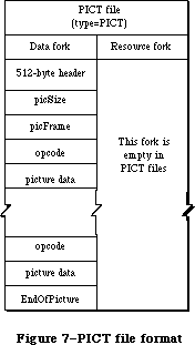 Figure 7–PICT file format.
_______________________________________________________________________________
»Picture Parsing
The first 512 bytes of a PICT data file contain application-specific header information. Each QuickDraw (and Color QuickDraw) picture definition consists of a fixed-size header containing information about the size, scaling, and version of the picture, followed by the opcodes and picture data defining the objects drawn between the OpenPicture and ClosePicture calls.
When the OpenPicture routine is called and the port is an old grafPort, a version 1 picture is opened. When the OpenPicture routine is called and the port is a cGrafPort, then a version 2 picture is opened. If any fields in the grafPort are different than the default entries, those fields that are different get recorded in the picture.
Version 4.1 of the Macintosh System file incorporates a patch to QuickDraw that will enable QuickDraw (on machines with 128K or larger ROMs) to parse a version 2 PICT file, read it completely, attempt to convert all Color QuickDraw color opcodes to a suitable black-and-white representation, and draw the picture in an old grafPort. If you are trying to display a version 2 picture on a Macintosh without the system patch, QuickDraw won’t be able to draw the picture.
_______________________________________________________________________________
»Picture Record Structure
The Pascal record structure of version 1 and version 2 pictures is exactly the same. In both, the picture begins with a picSize, then a picFrame (rect), followed by the picture definition data. Since a picture may include any sequence of drawing commands, its data structure is a variable-length entity. It consists of two fixed-length fields followed by a variable-length field:
TYPE Picture = RECORD
picSize: INTEGER; {low order 16 bits of picture }
{ size}
picFrame: Rect; {picture frame, used as }
{ reference for scaling when }
{ the picture is drawn }
{picture definition data}
END;
To maintain compatibility with the original picture format, the picSize field has not been changed in version 2 pictures. However, the information in this field is only useful if your application supports version 1 pictures not exceeding 32K bytes in size. Because pictures can be much larger than the 32K limit imposed by the 2-byte picSize field, use the GetHandleSize call to determine picture size if the picture is in memory or the file size returned in pBFGetInfo if the picture resides in a file.
The picFrame field is the picture frame that surrounds the picture and gives a frame of reference for scaling when the picture is played back. The rest of the structure contains a compact representation of the image defined by the opcodes. The picture definition data consists of a sequence of the opcodes listed in Table 3 in the Pict Opcodes section, each followed by zero or more bytes of data. Every opcode has an implicit or explicit size associated with it that indicates the number of data bytes following that opcode, ranging from 2 to
2^32 bytes (this maximum number of bytes applies to version 2 pictures only).
_______________________________________________________________________________
»Picture Spooling
In the past, images rarely exceeded the 32K practical limit placed on resources. Today, with the advent of scanners and other image input products, images may easily exceed this size. This increase in image size necessitates a means for handling pictures that are too large to reside entirely in memory. One solution is to place the picture in the data fork of a PICT file, and spool it in as needed. To read the file, an application can simply replace the QuickDraw default getPicProc routine with a procedure (getPICTData) that reads the picture data from a disk file; the disk access would be transparent. Note that this technique applies equally to version 1 (byte-opcode) and version 2
(word-opcode) pictures.
»Spooling a Picture From Disk
In order to display pictures of arbitrary size, an application must be able to import a QuickDraw picture from a file of type PICT. (This is the file type produced by a Save As command from MacDraw® with the PICT option selected.) What follows is a small program fragment that demonstrates how to spool in a picture from the data fork of a PICT file. The picture can be larger than the historical 32K resource size limitation.
{ The following variable and procedure must be at the }
{ main level of the program }
VAR
globalRef: INTEGER;
PROCEDURE GetPICTData(dataPtr: Ptr; byteCount: INTEGER);
{replacement for getPicProc routine}
VAR
err : INTEGER;
longCount: LONGINT;
BEGIN
longCount := byteCount;
{longCount is a Pascal VAR parameter and must be a LONGINT}
err := FSRead(globalRef,longCount,dataPtr);
{ignore errors here since it is unclear how to handle them}
END;
PROCEDURE GetandDrawPICTFile;
{procedure to draw in a picture from a PICT file selected by the user}
VAR
wher: Point; {where to display dialog}
reply: SFReply; {reply record}
myFileTypes: SFTypeList; {more of the Standard File goodies}
NumFileTypes: INTEGER;
err: OSErr;
myProcs: QDProcs; {use CQDProcs for a CGrafPort (a color }
{ window)}
PICTHand: PicHandle; {we need a picture handle for DrawPicture}
longCount: LONGINT;
myPB: ParamBlockRec;
BEGIN
wher.h := 20;
wher.v := 20;
NumFileTypes := 1; {Display PICT files}
myFileTypes[0] := 'PICT';
SFGetFile(wher,'',NIL,NumFileTypes,myFileTypes,NIL,reply);
IF reply.good THEN BEGIN
err := FSOpen(reply.fname,reply.vrefnum,globalRef);
SetStdProcs(myProcs); {use SetStdCProcs for a CGrafPort}
myWindow^.grafProcs := @myProcs;
myProcs.getPicProc := @GetPICTData;
PICTHand := PicHandle(NewHandle(SizeOf(Picture)));
{get one the size of (size word + frame rectangle)}
{skip (so to speak) the MacDraw header block}
err := SetFPos(globalRef,fsFromStart,512);
longCount := SizeOf(Picture);
{read in the (obsolete) size word and the picture frame}
err := FSRead(globalRef,longCount,Ptr(PICTHand^));
DrawPicture(PICTHand,PICTHand^^.picFrame);
{inside of DrawPicture, QD makes repeated calls to }
{ getPicProc to get actual picture opcodes and data. Since }
{ we have intercepted GetPicProc, QD will call myProcs to }
{ get getPicProc, instead of calling the default procedure}
err := FSClose(globalRef);
myWindow^.grafProcs := NIL;
DisposHandle(Handle(PICTHand));
END; {IF reply.good}
END;
»Spooling a Picture to a File
Spooling a picture out to a file is equally straightforward. By replacing the standard putPicProc with your own procedure, you can create a PICT file and spool the picture data out to the file.
Here is a sample of code to use as a guide:
{these variables and PutPICTData must be at the main program level}
VAR PICTcount: LONGINT; {the current size of the picture}
globalRef: INTEGER; {the file system reference number}
newPICThand: PicHandle;
{this is the replacement for the StdPutPic routine}
PROCEDURE PutPICTData(dataPtr: Ptr; byteCount: INTEGER);
VAR longCount: LONGINT;
err: INTEGER;
BEGIN {unfortunately, we don't know what to do with errors}
longCount := byteCount;
PICTCount := PICTCount + byteCount;
err := FSWrite(globalRef, longCount, dataPtr); {ignore error…}
IF newPICTHand <> NIL THEN newPICTHand^^.picSize := PICTCount;
{update so QD can track the size for oddness and pad out to full words}
END;
{Note that this assumes the picture is entirely in memory which wouldn't }
{ always be the case. You could (in effect) be feeding the StdGetPic }
{ procedure at the same time, or simply spooling while drawing.}
PROCEDURE SpoolOutPICTFile(PICTHand: PicHandle {the picture to spool});
VAR err: OSErr;
i: INTEGER;
wher: Point; { where to display dialog }
longCount, Zero: LONGINT;
pframe: Rect;
reply: SFReply; { reply record }
myProcs: QDProcs; {use CQDProcs for a CGrafPort (a color window)}
BEGIN
wher.h := 20;
wher.v := 20;
{get a file to output to}
SFPutFile(wher, 'Save the PICT as:', 'untitled', NIL, reply);
IF reply.good THEN
BEGIN
err := Create(reply.fname, reply.vrefnum, '????', 'PICT');
IF (err = noerr) | (err = dupfnerr) THEN
BEGIN
{now open the target file and prepare to spool to it}
signal(FSOpen(reply.fname, reply.vrefnum, globalRef));
SetStdProcs(myProcs); {use SetStdCProcs for a CGrafPort}
myWindow^.grafProcs := @myProcs;
myProcs.putPicProc := @putPICTdata;
Zero := 0;
longCount := 2;
PICTCount := SizeOf(Picture);
{now write out the 512 byte header and zero (initially) the}
{ Picture structure}
FOR i := 1 TO (512 + SizeOf(Picture)) DIV longCount DO
Signal(FSWrite(globalRef, longCount, @Zero));
{open a new picture and draw the old one to it; this will convert}
{ the old picture to fit the type of GrafPort to which we are}
{ currently set}
pFrame := PICThand^^.picFrame;
newPICTHand := NIL;
newPICTHand := OpenPicture(pFrame);
DrawPicture(PICTHand, pFrame); {draw the picture so the
bottleneck will be used. In real life you could be spooling while
doing drawing commands (you might not use DrawPicture)}
ClosePicture;
Signal(SetFPos(globalRef, fsFromStart, 512));
{skip the MacDraw header}
longCount := SizeOf(Picture);
{write out the correct (low word of the) size and the frame at}
{ the beginning}
Signal(FSWrite(globalRef, longCount, Ptr(newPICTHand^)));
Signal(FSClose(globalRef));
myWindow^.grafProcs := NIL;
KillPicture(newPICTHand);
END
ELSE
Signal(err);
END; {IF reply.good}
END; {OutPICT}
»Drawing to an Offscreen Pixel Map
With the advent of high resolution output devices such as laser printers, it has become necessary to support bitmap images at resolutions higher than those supported by the screen. To speed up the interactive manipulation of high-resolution pixel map images, developers may want to first draw them into an off screen pixel map at screen resolution and retain this screen version as long as the document is open.
Note: You can use the formula shown in the section “Sample PICT file” to
calculate the resolution of the source data. How to draw into an
offscreen pixmap is described in Macintosh Technical Note #120,
“Drawing Into an Off-Screen Pixel Map”; the Graphics Devices chapter
also contains a section describing how to draw to an offscreen device.
_______________________________________________________________________________
»New GrafProcs Record
The entire opcode space has been defined or reserved, as shown in the PICT Opcodes section in Table 3, and a new set of routines has been added to the grafProcs record. These changes provide support for anticipated future enhancements in a way that won’t cause old applications to crash. It works like this: when Color QuickDraw encounters an unused opcode, it calls the new opcodeProc routine to parse the opcode data. By default, this routine simply ignores the data, since no new opcodes are defined (other than HeaderOp, which is also ignored).
Color QuickDraw has replaced the QDProcs record with a CQDProcs record. In a new grafPort, you should never use the SetStdProcs routine. If you do, it will return the old QDProcs record, which won’t contain an entry for the stdOpcodeProc. If you don’t use the new SetStdCProcs routine, the first color picture that you try to display may crash your system.
The CQDProcs record structure is shown below. Only the last seven fields are new; the rest of the fields are the same as those in the QDProcs record.
CQDProcsPtr = ^CQDProcs
CQDProcs = RECORD
textProc: Ptr;
lineProc: Ptr;
rectProc: Ptr;
rRectProc: Ptr;
ovalProc: Ptr;
arcProc: Ptr;
polyProc: Ptr;
rgnProc: Ptr;
bitsProc: Ptr;
commentProc: Ptr;
txMeasProc: Ptr;
getPicProc: Ptr;
putPicProc: Ptr;
opcodeProc: Ptr; {fields added to QDProcs}
newProc1: Ptr; {reserved for future use}
newProc2: Ptr; {reserved for future use}
newProc3: Ptr; {reserved for future use}
newProc4: Ptr; {reserved for future use}
newProc5: Ptr; {reserved for future use}
newProc6: Ptr; {reserved for future use}
END;
_______________________________________________________________________________
»Picture Compatibility
Many applications already support PICT resources larger than 32K. The 128K ROMs (and later) allow pictures as large as memory (or spooling) will accommodate. This was made possible by having QuickDraw ignore the size word and simply read the picture until the end-of-picture opcode is reached.
Note: For maximum safety and convenience, let QuickDraw generate and
interpret your pictures.
While the PICT data formats described in this section allow you to read or write picture data directly, it’s best to let DrawPicture or OpenPicture and ClosePicture process the opcodes.
One reason to read a picture directly by scanning the opcodes is to disassemble it; for example, extracting a Color QuickDraw pixel map to store in a private data structure. This shouldn’t normally be necessary, unless your application is running on a CPU other than the Macintosh. You wouldn’t need to do it, of course, if you were using Color QuickDraw.
If your application does use the picture data, be sure it checks the version information. You may want to include an alert box in your application, indicating to users whether a picture was created using a later version of the picture format than is currently recognized by your application, and letting them know that some elements of the picture can’t be displayed. If the version information indicates a QuickDraw picture version later than the one recognized by your application, your program should skip over the new opcodes and only attempt to parse the opcodes it knows.
As with reading picture data directly, it’s best to use QuickDraw to create data in the PICT format. If you need to create PICT format data directly, it’s essential that you understand and follow the format presented in Table 3 and thoroughly test the data produced on both color and black and white Macintosh machines.
_______________________________________________________________________________
»Picture Format
This section describes the internal structure of the QuickDraw picture, consisting of a fixed-length header (which is different for version 1 and version 2 pictures), followed by variable-sized picture data. Your picture structure must follow the order shown in the examples below.
The two fixed-length fields, picSize and picFrame, are the same for version 1 and version 2 pictures.
picSize: INTEGER; {low-order 16 bits of picture size}
picFrame: RECT; {picture frame, used as scaling reference}
Following these fields is a variable amount of opcode-driven data. Opcodes represent drawing commands and parameters that affect those drawing commands in the picture. The first opcode in any picture must be the version opcode, followed by the version number of the picture.
»Picture Definition: Version 1
In a version 1 picture, the version opcode is $11, which is followed by version number $01. When parsing a version 1 picture, Color QuickDraw (or a patched QuickDraw) assumes it’s reading an old picture, fetching a byte at a time as opcodes. An end-of-picture byte ($FF) after the last opcode or data byte in the file signals the end of the data stream.
Picture Header (fixed size of 2 bytes):
$11 BYTE {version opcode}
$01 BYTE {version number of picture}
Picture Definition Data (variable sized):
opcode BYTE {one drawing command}
data . . .
opcode BYTE {one drawing command}
data . . .
$FF {end-of-picture opcode}
»Picture Definition: Version 2
In a version 2 picture, the first opcode is a two-byte version opcode ($0011). This is followed by a two-byte version number ($02FF). On machines without the 4.1 System file, the first $00 byte is skipped, then the $11 is interpreted as a version opcode. On a Macintosh II (or a Macintosh with System file 4.1 or later), this field identifies the picture as a version 2 picture, and all subsequent opcodes are read as words (which are word-aligned within the
picture). On a Macintosh without the 4.1 System patch, the $02 is read as the version number, then the $FF is read and interpreted as the end-of-picture opcode. For this reason, DrawPicture terminates without drawing anything.
Picture Header (fixed size of 30 bytes):
$0011 WORD {version opcode}
$02FF WORD {version number of new picture}
$0C00 WORD {reserved header opcode}
24 bytes of data {reserved for future Apple use}
Picture Definition Data (variable sized):
opcode WORD {one drawing command}
data . . .
opcode WORD {one drawing command}
data . . .
$00FF WORD {end-of-picture opcode}
For future expandibility, the second opcode in every version 2 picture must be a reserved header opcode, followed by 24 bytes of data that aren’t used by your application.
»PicComments
If your application requires capability beyond that provided by the picture opcodes, the picComment opcode allows data or commands to be passed directly to the output device. PicComments enable MacDraw, for example, to reconstruct graphics primitives not found in QuickDraw (such as rotated text) that are received either from the Clipboard or from another application. PicComments are also used as a means of communicating more effectively with the LaserWriter and with other applications via the scrap or the PICT data file.
Because some operations (like splines and rotated text) can be implemented more efficiently by the LaserWriter, some of the picture comments are designed to be issued along with QuickDraw commands that simulate the commented commands on the Macintosh screen. If the printer you are using has not implemented the comment commands, it ignores them and simulates the operations using the accompanying QuickDraw commands. Otherwise, it uses the comments to implement the desired effect and ignores the appropriate QuickDraw-simulated commands.
If you are going to produce or modify your own picture, the structure and use of these comments must be precise. The comments and the embedded QuickDraw commands must come in the correct sequence in order to work properly.
Note: Apple is currently investigating a method to register picComments.
If you intend to use new picComments in your application, you must
contact Apple’s Developer Technical Support to avoid conflict with
picComment numbers used by other developers.
»Sample PICT File
An example of a version 2 picture data file that can display a single image is shown in Table 1. Applications that generate picture data should set the resolution of the image source data in the hRes and vRes fields of the PICT file. It’s recommended, however, that you calculate the image resolution anyway, using the values for srcRect and dstRect according to the following formulas:
horizontal resolution (hRes) = width of srcRect x 72
________________
width of dstRect
vertical resolution (vRes) = height of srcRect x 72
_________________
height of dstRect
Table 1–PICT file example
_______________________________________________________________________________
Size Name Description
(in bytes)
2 picSize low word of picture size
8 picFrame rectangular bounding box of picture,
at 72 dpi
Picture Definition Data:
2 version op version opcode = $0011
2 version version number = $02FF
2 Header op header opcode = $0C00
4 size total size of picture in bytes
(–1 for version 2 pictures)
16 fBBox fixed-point bounding box
(–1 for version 2 pictures)
4 reserved reserved for future Apple use
(–1 for version 2 pictures)
2 opbitsRect bitMap opcode = $0090
2 rowBytes integer, must have high bit set to
signal pixMap
8 bounds rectangle, bounding rectangle at
source resolution
2 pmVersion integer, pixMap version number
2 packType integer, defines packing format
4 packSize LongInt, length of pixel data
4 hRes fixed, horizontal resolution (dpi) of
source data
4 vRes fixed, vertical resolution (dpi) of
source data
2 pixelType integer, defines pixel type
2 pixelSize integer, number of bits in pixel
2 cmpCount integer, number of components in pixel
2 cmpSize integer, number of bits per component
4 planeBytes LongInt, offset to next plane
pmTable color table = 0
pmReserved reserved = 0
4 ctSeed LongInt, color table seed
2 ctFlags integer, flags for color table
2 ctSize integer, number of entries in ctTable –1
(ctSize+1) * 8 ctTable color lookup table data
8 srcRect rectangle, source rectangle at source
resolution
8 dstRect rectangle, destination rectangle at 72 dpi
resolution
2 mode integer, transfer mode
see Table 5 pixData pixel data
2 endPICT op end-of-picture opcode = $00FF
_______________________________________________________________________________
_______________________________________________________________________________
»Color Picture Routines
FUNCTION OpenPicture (picFrame: Rect) : PicHandle;
The OpenPicture routine has been modified to take advantage of QuickDraw’s new color capabilities. If the current port is a cGrafPort, then OpenPicture automatically opens a version 2 picture, as described in the previous section. As before, you close the picture using ClosePicture and draw the picture using DrawPicture.
_______________________________________________________________________________
»PICT OPCODES
_______________________________________________________________________________
The opcode information in Table 3 is provided for the purpose of debugging application-generated PICT files. Your application should generate and read PICT files only by using standard QuickDraw or Color QuickDraw routines
(OpenPicture, ClosePicture).
The data types listed in Table 2 are used in the Table 3 opcode definitions. Data formats are described in Volume I.
Table 2–Data types
_______________________________________________________________________________
Type Size
v1 opcode 1 byte
v2 opcode 2 bytes
integer 2 bytes
long integer 4 bytes
mode 2 bytes
point 4 bytes
0..255 1 byte
–128..127 1 byte (signed)
rect 8 bytes (top, left, bottom, right: integer)
poly 10+ bytes
region 10+ bytes
fixed-point number 4 bytes
pattern 8 bytes
rowbytes 2 bytes (always an even quantity)
_______________________________________________________________________________
Valid picture opcodes are listed in Table 3. New opcodes or those altered for version 2 picture files are indicated by a leading asterisk (*). The unused opcodes found throughout the table are reserved for Apple use. The length of the data that follows these opcodes is pre-defined, so if they are encountered in pictures, they can simply be skipped. By default, Color QuickDraw reads and then ignores these opcodes.
Table 3–PICT opcodes
_______________________________________________________________________________
Opcode Name Description Data Size
(in bytes)
$0000 NOP nop 0
$0001 Clip clip region size
$0002 BkPat background pattern 8
$0003 TxFont text font (word) 2
$0004 TxFace text face (byte) 1
$0005 TxMode text mode (word) 2
$0006 SpExtra space extra (fixed point) 4
$0007 PnSize pen size (point) 4
$0008 PnMode pen mode (word) 2
$0009 PnPat pen pattern 8
$000A FillPat fill pattern 8
$000B OvSize oval size (point) 4
$000C Origin dh, dv (word) 4
$000D TxSize text size (word) 2
$000E FgColor foreground color (long) 4
$000F BkColor background color (long) 4
$0010 TxRatio numer (point), denom (point) 8
$0011 Version version (byte) 1
$0012 *BkPixPat color background pattern variable:
see Table 4
$0013 *PnPixPat color pen pattern variable:
see Table 4
$0014 *FillPixPat color fill pattern variable:
see Table 4
$0015 *PnLocHFrac fractional pen position 2
$0016 *ChExtra extra for each character 2
$0017 *reserved for Apple use opcode 0
$0018 *reserved for Apple use opcode 0
$0019 *reserved for Apple use opcode 0
$001A *RGBFgCol RGB foreColor variable:
see Table 4
$001B *RGBBkCol RGB backColor variable:
see Table 4
$001C *HiliteMode hilite mode flag 0
$001D *HiliteColor RGB hilite color variable:
see Table 4
$001E *DefHilite Use default hilite color 0
$001F *OpColor RGB OpColor for variable:
arithmetic modes see Table 4
$0020 Line pnLoc (point), newPt (point) 8
$0021 LineFrom newPt (point) 4
$0022 ShortLine pnLoc (point, dh, dv 6
(-128..127)
$0023 ShortLineFrom dh, dv (-128..127) 2
$0024 *reserved for Apple use opcode + 2 bytes data 2+ data
length + data length
$0025 *reserved for Apple use opcode + 2 bytes data 2+ data
length + data length
$0026 *reserved for Apple use opcode + 2 bytes data 2+ data
length + data length
$0027 *reserved for Apple use opcode + 2 bytes data 2+ data
length + data length
$0028 LongText txLoc (point), count 5 + text
(0..255), text
$0029 DHText dh (0..255), count 2 + text
(0..255), text
$002A DVText dv (0..255), count 2 + text
(0..255), text
$002B DHDVText dh, dv (0..255), count 3 + text
(0..255), text
$002C *reserved for Apple use opcode + 2 bytes data 2+ data
length + data length
$002D *reserved for Apple use opcode + 2 bytes data 2+ data
length + data length
$002E *reserved for Apple use opcode + 2 bytes data 2+ data
length + data length
$002F *reserved for Apple use opcode + 2 bytes data 2+ data
length + data length
$0030 frameRect rect 8
$0031 paintRect rect 8
$0032 eraseRect rect 8
$0033 invertRect rect 8
$0034 fillRect rect 8
$0035 *reserved for Apple use opcode + 8 bytes data 8
$0036 *reserved for Apple use opcode + 8 bytes data 8
$0037 *reserved for Apple use opcode + 8 bytes data 8
$0038 frameSameRect rect 0
$0039 paintSameRect rect 0
$003A eraseSameRect rect 0
$003B invertSameRect rect 0
$003C fillSameRect rectangle 0
$003D *reserved for Apple use opcode 0
$003E *reserved for Apple use opcode 0
$003F *reserved for Apple use opcode 0
$0040 frameRRect rect (see Note # 5 ) 8
$0041 paintRRect rect (see Note # 5 ) 8
$0042 eraseRRect rect (see Note # 5 ) 8
$0043 invertRRect rect (see Note # 5 ) 8
$0044 fillRRect rect (see Note # 5 ) 8
$0045 *reserved for Apple use opcode + 8 bytes data 8
$0046 *reserved for Apple use opcode + 8 bytes data 8
$0047 *reserved for Apple use opcode + 8 bytes data 8
$0048 frameSameRRect rect 0
$0049 paintSameRRect rect 0
$004A eraseSameRRect rect 0
$004B invertSameRRect rect 0
$004C fillSameRRect rect 0
$004D *reserved for Apple use opcode 0
$004E *reserved for Apple use opcode 0
$004F *reserved for Apple use opcode 0
$0050 frameOval rect 8
$0051 paintOval rect 8
$0052 eraseOval rect 8
$0053 invertOval rect 8
$0054 fillOval rect 8
$0055 *reserved for Apple use opcode + 8 bytes data 8
$0056 *reserved for Apple use opcode + 8 bytes data 8
$0057 *reserved for Apple use opcode + 8 bytes data 8
$0058 frameSameOval rect 0
$0059 paintSameOval rect 0
$005A eraseSameOval rect 0
$005B invertSameOval rect 0
$005C fillSameOval rect 0
$005D *reserved for Apple use opcode 0
$005E *reserved for Apple use opcode 0
$005F *reserved for Apple use opcode 0
$0060 frameArc rect, startAngle, arcAngle 12
$0061 paintArc rect, startAngle, arcAngle 12
$0062 eraseArc rect, startAngle, arcAngle 12
$0063 invertArc rect, startAngle, arcAngle 12
$0064 fillArc rect, startAngle, arcAngle 12
$0065 *reserved for Apple use opcode + 12 bytes 12
$0066 *reserved for Apple use opcode + 12 bytes 12
$0067 *reserved for Apple use opcode + 12 bytes 12
$0068 frameSameArc rect 4
$0069 paintSameArc rect 4
$006A eraseSameArc rect 4
$006B invertSameArc rect 4
$006C fillSameArc rect 4
$006D *reserved for Apple use opcode + 4 bytes 4
$006E *reserved for Apple use opcode + 4 bytes 4
$006F *reserved for Apple use opcode + 4 bytes 4
size
$0070 framePoly poly polygon
size
$0071 paintPoly poly polygon
size
$0072 erasePoly poly polygon
size
$0073 invertPoly poly polygon
size
$0074 fillPoly poly polygon
size
$0075 *reserved for Apple use opcode + poly
$0076 *reserved for Apple use opcode + poly
$0077 *reserved for Apple use opcode word + poly
$0078 frameSamePoly (not yet implemented: 0
same as 70, etc)
$0079 paintSamePoly (not yet implemented) 0
$007A eraseSamePoly (not yet implemented) 0
$007B invertSamePoly (not yet implemented) 0
$007C fillSamePoly (not yet implemented) 0
$007D *reserved for Apple use opcode 0
$007E *reserved for Apple use opcode 0
$007F *reserved for Apple use opcode 0
$0080 frameRgn rgn region size
$0081 paintRgn rgn region size
$0082 eraseRgn rgn region size
$0083 invertRgn rgn region size
$0084 fillRgn rgn region size
$0085 *reserved for Apple use opcode + rgn region size
$0086 *reserved for Apple use opcode + rgn region size
$0087 *reserved for Apple use opcode + rgn region size
$0088 frameSameRgn (not yet implemented: 0
same as 80, etc.)
$0089 paintSameRgn (not yet implemented) 0
$008A eraseSameRgn (not yet implemented) 0
$008B invertSameRgn (not yet implemented) 0
$008C fillSameRgn (not yet implemented) 0
$008D *reserved for Apple use opcode 0
$008E *reserved for Apple use opcode 0
$008F *reserved for Apple use opcode 0
$0090 *BitsRect copybits, rect clipped variable:
see Table 4
$0091 *BitsRgn copybits, rgn clipped variable:
see Table 4
$0092 *reserved for Apple use opcode + 2 bytes data 2+ data
length + data length
$0093 *reserved for Apple use opcode + 2 bytes data 2+ data
length + data length
$0094 *reserved for Apple use opcode + 2 bytes data 2+ data
length + data length
$0095 *reserved for Apple use opcode + 2 bytes data 2+ data
length + data length
$0096 *reserved for Apple use opcode + 2 bytes data 2+ data
length + data length
$0097 *reserved for Apple use opcode word + 2 bytes 2+ data
data length + data length
$0098 *PackBitsRect packed copybits, rect variable:
clipped see Table 4
$0099 *PackBitsRgn packed copybits, rgn variable:
clipped see Table 4
$009A *reserved for Apple use opcode + 2 bytes data 2+ data
length + data length
$009B *reserved for Apple use opcode + 2 bytes data 2+ data
length + data length
$009C *reserved for Apple use opcode + 2 bytes data 2+ data
length + data length
$009D *reserved for Apple use opcode + 2 bytes data 2+ data
length + data length
$009E *reserved for Apple use opcode + 2 bytes data 2+ data
length + data length
$009F *reserved for Apple use opcode + 2 bytes data 2+ data
length + data length
$00A0 ShortComment kind (word) 2
$00A1 LongComment kind (word), size 4+data
(word), data
$00A2 *reserved for Apple use opcode + 2 bytes data 2+ data
length + data length
: : :
: : :
$00AF *reserved for Apple use opcode + 2 bytes data 2+ data
length + data length
$00B0 *reserved for Apple use opcode 0
: : :
: : :
$00CF *reserved for Apple use opcode 0
$00D0 *reserved for Apple use opcode + 4 bytes data 4+ data
length + data length
: : :
: : :
$00FE *reserved for Apple use opcode + 4 bytes data 4+ data
length + data length
$00FF opEndPic end of picture 2
$0100 *reserved for Apple use opcode + 2 bytes data 2
: : :
: : :
$01FF *reserved for Apple use opcode + 2 bytes data 2
$0200 *reserved for Apple use opcode + 4 bytes data 4
: : :
$0BFF *reserved for Apple use opcode + 4 bytes data 22
$0C00 HeaderOp opcode 24
$0C01 *reserved for Apple use opcode + 4 bytes data 24
: : :
$7F00 *reserved for Apple use opcode + 254 bytes data 254
: : :
$7FFF *reserved for Apple use opcode + 254 bytes data 254
$8000 *reserved for Apple use opcode 0
: : :
$80FF *reserved for Apple use opcode 0
$8100 *reserved for Apple use opcode + 4 bytes data 4+ data
length + data length
: : :
$FFFF *reserved for Apple use opcode + 4 bytes data 4+ data
length + data length
_______________________________________________________________________________
Notes to Table 3
1. The opcode value has been extended to a word for version 2 pictures.
Remember, opcode size = 1 byte for version 1.
2. Because opcodes must be word aligned in version 2 pictures, a byte
of 0 (zero) data is added after odd-size data.
3. The size of reserved opcodes has been defined. They can occur only
in version 2 pictures.
4. All unused opcodes are reserved for future Apple use and should
not be used.
5. For opcodes $0040–$0044: rounded-corner rectangles use the setting
of the ovSize point (refer to opcode $000B)
6. For opcodes $0090 and $0091: data is unpacked. These opcodes can
only be used for rowbytes less than 8.
7. For opcodes $0100–$7FFF: the amount of data for opcode
$nnXX = 2 * nn bytes.
_______________________________________________________________________________
»The New Opcodes: Expanded Format
The expanded format of the version 2 PICT opcodes is shown in Table 4 below.
Table 4–Data Format of Version 2 PICT Opcodes
_______________________________________________________________________________
Opcode Name Description Reference to Notes
$0012 BkPixPat color background pattern See Note 1
$0013 PnPixPat color pen pattern See Note 1
$0014 FillPixPat color fill pattern See Note 1
$0015 PnLocHFrac fractional pen If pnLocHFrac <> 1/2, it
position (word) is always put to the
picture before each
text drawing operation.
$0016 ChExtra extra for each After chExtra changes,
character (word) it is put to picture
before next text
drawing operation.
$001A RGBFgCol RGB foreColor (RBGColor) desired RGB for
foreground
$001B RGBBkCol RGB backColor (RGBColor) desired RGB for
background
$001D HiliteColor RGB hilite color
$001F OpColor RGB OpColor for
arithmetic modes
$001C HiliteMode hilite mode flag No data; this opcode is
sent before a drawing
operation that uses the
hilite mode.
$001E DefHilite Use default hilite No data; set hilite
color to default (from low
memory).
$0090 BitsRect copybits, rect See Note 2,4,5
clipped
$0091 BitsRgn copybits, rgn See Note 3,4,5
clipped
$0098 PackBitsRect packed copybits, See Note 2,4
rect clipped
$0099 PackBitsRgn packed copybits, See Note 3,4
rgn clipped
_______________________________________________________________________________
Notes to Table 4
1. if patType = ditherPat
then
PatType: word; {pattern type = 2}
Pat1Data: Pattern; {old pattern data}
RGB: RGBColor; {desired RGB for pattern}
else
PatType: word; {pattern type = 1}
Pat1Data: Pattern; {old pattern data}
pixMap: {described in Table 5}
colorTable: {described in Table 5}
pixData: {described in Table 5}
end;
2. pixMap: {described in Table 5}
colorTable: {described in Table 5}
srcRect: Rect; {source rectangle}
dstRect: Rect; {destination rectangle}
mode: Word; {transfer mode (may include new transfer }
{ modes)}
PixData: {described in Table 5}
3. pixMap: {described in Table 5 }
colorTable: {described in Table 5 }
srcRect: Rect; {source rectangle}
dstRect: Rect; {destination rectangle}
mode: Word; {transfer mode (may include new transfer }
{ modes)}
maskRgn: Rgn; {region for masking}
PixData: {described in Table 5}
4. These four opcodes ($0090, $0091, $0098, $0099) are modifications of
existing (version 1) opcodes. The first word following the opcode is
the rowBytes. If the high bit of the rowBytes is set, then it is a
pixMap containing multiple bits per pixel; if it is not set, it is a
bitMap containing one bit per pixel. In general, the difference between
version 1 and version 2 formats is that the pixMap replaces the bitMap,
a color table has been added, and pixData replaces the bitData.
5. Opcodes $0090 and $0091 are used only for rowbytes less than 8.
Table 5–Data Types Found Within New PICT Opcodes Listed in Table 4
_______________________________________________________________________________
Data Type Field Definitions Comments
pixMap = baseAddr: long; {unused = 0}
rowBytes: word; {rowBytes w/high byte set}
Bounds: rect; {bounding rectangle}
version: word; {version number = 0}
packType: word; {packing format = 0}
packSize: long; {packed size = 0}
hRes: fixed; {horizontal resolution (default = }
{ $0048.0000)}
vRes: fixed; {vertical resolution (default= }
{ $0048.0000)}
pixelType: word; {chunky format = 0}
pixelSize: word; {# bits per pixel (1,2,4,8)}
cmpCount: word; {# components in pixel = 1}
cmpSize: word; {size of each component = pixelSize }
{ for chunky}
planeBytes: long; {offset to next plane = 0}
pmTable: long; {color table = 0}
pmReserved: long; {reserved = 0}
end;
colorTable = ctSeed: long; {id number for color table = 0}
ctFlags: word; {flags word = 0}
ctSize: word; {number of ctTable entries-1 }
{ ctSize + 1 color table entries }
{ each entry = pixel value, red, }
{ green, blue: word}
end;
pixData: {the following pseudocode describes the pixData data type}
If rowBytes < 8 then data is unpacked
data size = rowBytes*(bounds.bottom-bounds.top);
If rowBytes >= 8 then data is packed.
Image contains (bounds.bottom-bounds.top) packed scanlines.
Packed scanlines are produced by the PackBits routine.
Each scanline consists of [byteCount] [data].
If rowBytes > 250 then byteCount is a word,
else it is a byte.
end;
_______________________________________________________________________________
»SUMMARY OF COLOR QUICKDRAW
_______________________________________________________________________________
Constants
CONST
{ Old-style grafPort colors }
blackColor = 33;
whiteColor = 30;
redColor = 209;
greenColor = 329;
blueColor = 389;
cyanColor = 269;
magentaColor = 149;
yellowColor = 89;
{ Arithmetic transfer modes }
blend = 32;
addPin = 33;
addOver = 34;
subPin = 35;
adMax = 37;
subOver = 38;
adMin = 39;
{ Transparent mode constant }
transparent = 36;
{ Text mask constant }
mask = 64;
{ Highlight constants }
hilite = 50;
pHiliteBit = 0; {this is the correct value for use when }
{ calling the BitClear trap. BClr must use }
{ the assembly language equate hiliteBit}
{ Constant for resource IDs }
defQDColors = 127;
_______________________________________________________________________________
Data Types
TYPE
RGBColor = RECORD
red: INTEGER; {red component}
green: INTEGER; {green component}
blue: INTEGER {blue component}
END;
ColorSpec = RECORD
value: INTEGER; {index or other value}
rgb: RGBColor {true color}
END;
cSpecArray : ARRAY [0..0] of ColorSpec;
CTabHandle = ^CTabPtr;
CTabPtr = ^ColorTable;
ColorTable = RECORD
ctSeed: LONGINT; {unique identifier from table}
ctFlags: INTEGER; {high bit is 1 for device, 0 }
{ for pixMap}
ctSize: INTEGER; {number of entries -1 in }
{ ctTable}
ctTable: cSpecArray
END;
CGrafPtr = ^CGrafPort;
CGrafPort = RECORD
device: INTEGER; {device ID for font selection}
portPixMap: PixMapHandle; {port's pixel map}
portVersion: INTEGER; {highest 2 bits always set}
grafVars: Handle; {handle to more fields}
chExtra: INTEGER; {extra characters placed}
{ on the end of a string}
pnLocHFrac: INTEGER; {pen fraction}
portRect: Rect; {port rectangle}
visRgn: RgnHandle; {visible region}
clipRgn: RgnHandle; {clipping region}
bkPixPat: PixPatHandle; {background pattern}
rgbFgColor: RGBColor; {requested foreground color}
rgbBkColor: RGBColor; {requested background color}
pnLoc: Point; {pen location}
pnSize: Point; {pen size}
pnMode: INTEGER; {pen transfer mode}
pnPixPat: PixPatHandle; {pen pattern}
fillPixPat: PixPatHandle; {fill pattern}
pnVis: INTEGER; {pen visibility}
txFont: INTEGER; {font number for text}
txFace: Style; {text's character style}
txMode: INTEGER; {text's transfer mode}
txSize: INTEGER; {font size for text}
spExtra: Fixed; {extra space}
fgColor: LONGINT; {actual foreground color}
bkColor: LONGINT; {actual background color}
colrBit: INTEGER; {plane being drawn}
patStretch: INTEGER; {used internally}
picSave: Handle; {picture being saved}
rgnSave: Handle; {region being saved}
polySave: Handle; {polygon being saved}
grafProcs: CQDProcsPtr {low-level drawing routines}
END;
GrafVars = RECORD
rgbOpColor: RGBColor; {color for addPin, }
{ subPin, and blend}
rgbHiliteColor: RGBColor; {color for hiliting}
pmFgColor: Handle; {palette handle for }
{ foreground color}
pmFgIndex: INTEGER; {index value for foreground}
pmBkColor: Handle; {palette handle for }
{ background color}
pmBkIndex: INTEGER; {index value for background}
pmFlags: INTEGER; {flags for Palette Manager}
END;
PixMapHandle = ^PixMapPtr;
PixMapPtr = ^PixMap;
PixMap = RECORD
baseAddr: Ptr; {pointer to pixMap data}
rowBytes: INTEGER; {offset to next row}
bounds: Rect; {boundary rectangle}
pmVersion: INTEGER; {color QuickDraw version number}
packType: INTEGER; {packing format}
packSize: LONGINT; {size of data in packed state}
hRes: Fixed; {horizontal resolution}
vRes: Fixed; {vertical resolution}
pixelType: INTEGER; {format of pixel image}
pixelSize: INTEGER; {physical bits per pixel}
cmpCount: INTEGER; {logical components per pixel}
cmpSize: INTEGER; {logical bits per component}
planeBytes: LONGINT; {offset to next plane}
pmTable: CTabHandle; {absolute colors for this image}
pmReserved: LONGINT {reserved for future expansion}
END;
PixPatHandle = ^PixPatPtr;
PixPatPtr = ^PixPat;
PixPat = RECORD
patType: INTEGER; {pattern type}
patMap: PixMapHandle; {pattern characteristics}
patData: Handle; {pixel image defining pattern}
patXData: Handle; {expanded pixel image}
patXValid: INTEGER; {flags for expanded pattern data}
patXMap: Handle; {handle to expanded pattern data}
pat1Data: Pattern; {old-style pattern/RGB color}
END;
CCrsrHandle = ^CCrsrPtr;
CCrsrPtr = ^CCrsr;
CCrsr = RECORD
crsrType: INTEGER; {type of cursor}
crsrMap: PixMapHandle; {the cursor's pixMap}
crsrData: Handle; {cursor's data}
crsrXData: Handle; {expanded cursor data}
crsrXValid: INTEGER; {depth of expanded data}
crsrXHandle: Handle; {reserved for future use}
crsr1Data: Bits16; {one-bit cursor}
crsrMask: Bits16; {cursor's mask}
crsrHotSpot: Point; {cursor's hotspot}
crsrXTable: LONGINT; {private}
crsrID: LONGINT; {ctSeed for expanded cursor}
END;
CIconHandle = ^CIconPtr;
CIconPtr = ^CIcon;
CIcon = RECORD
iconPMap: PixMap; {the icon's pixMap}
iconMask: BitMap; {the icon's mask bitMap}
iconBMap: BitMap; {the icon's bitMap}
iconData: Handle; {the icon's data}
iconMaskData: ARRAY[0..0] OF INTEGER; {icon's }
{ mask and bitMap data}
END;
MatchRec = RECORD
red: INTEGER; {red component}
green: INTEGER; {green component}
blue: INTEGER; {blue component}
matchData: LONGINT;
END;
CQDProcsPtr = ^CQDProcs
CQDProcs = RECORD
textProc: Ptr;
lineProc: Ptr;
rectProc: Ptr;
rRectProc: Ptr;
ovalProc: Ptr;
arcProc: Ptr;
polyProc: Ptr;
rgnProc: Ptr;
bitsProc: Ptr;
commentProc: Ptr;
txMeasProc: Ptr;
getPicProc: Ptr;
putPicProc: Ptr;
opcodeProc: Ptr; {fields added to QDProcs}
newProc1: Ptr; {reserved for future use}
newProc2: Ptr; {reserved for future use}
newProc3: Ptr; {reserved for future use}
newProc4: Ptr; {reserved for future use}
newProc5: Ptr; {reserved for future use}
newProc6: Ptr; {reserved for future use}
END;
_______________________________________________________________________________
Routines
Operations on cGrafPorts
PROCEDURE OpenCPort (port: CGrafPtr);
PROCEDURE InitCPort (port: CGrafPtr);
PROCEDURE CloseCPort (port: CGrafPtr);
Setting the Foreground and Background Colors
PROCEDURE RGBForeColor (color : RGBColor);
PROCEDURE RGBBackColor (color : RGBColor);
PROCEDURE GetForeColor (VAR color : RGBColor);
PROCEDURE GetBackColor (VAR color : RGBColor);
Creating Pixel Maps
FUNCTION NewPixMap : PixMapHandle;
PROCEDURE DisposPixMap (pm: PixMapHandle);
PROCEDURE CopyPixMap (srcPM,dstPM: PixMapHandle);
Operations on Pixel Maps
PROCEDURE CopyBits (srcBits, dstBits: BitMap; srcRect, dstRect: Rect;
mode: INTEGER; maskRgn: RgnHandle);
PROCEDURE CopyMask (srcBits,maskBits,dstBits: BitMap;
srcRect, maskRect, dstRect: Rect);
PROCEDURE SeedCFill (srcBits, dstBits: BitMap; srcRect, dstRect: Rect;
seedH, seedV: INTEGER; matchProc: ProcPtr;
matchData: LONGINT);
PROCEDURE CalcCMask (srcBits, dstBits: BitMap; srcRect, dstRect: Rect;
seedRGB: RGBColor; matchProc: ProcPtr; matchData: LONGINT);
Operations on Pixel Patterns
FUNCTION NewPixPat : PixPatHandle;
PROCEDURE DisposPixPat (ppat: PixPatHandle);
FUNCTION GetPixPat (patID: INTEGER): PixPatHandle;
PROCEDURE CopyPixPat (srcPP,dstPP: PixPatHandle);
PROCEDURE MakeRGBPat (ppat: PixPatHandle; myColor: RGBColor);
PROCEDURE PenPixPat (ppat: PixPatHandle);
PROCEDURE BackPixPat (ppat: PixPatHandle);
Color Drawing Operations
PROCEDURE FillCRect (r: Rect; ppat: PixPatHandle);
PROCEDURE FillCOval (r: Rect; ppat: PixPatHandle);
PROCEDURE FillCRoundRect (r: Rect; ovWd,ovHt: INTEGER; ppat: PixPatHandle);
PROCEDURE FillCArc (r: Rect; startAngle,arcAngle: INTEGER;
ppat: PixPatHandle);
PROCEDURE FillCRgn (rgn: RgnHandle; ppat: PixPatHandle);
PROCEDURE FillCPoly (poly: PolyHandle; ppat: PixPatHandle);
PROCEDURE GetCPixel (h,v: INTEGER; VAR cPix: RGBColor);
PROCEDURE SetCPixel (h,v: INTEGER; cPix: RGBColor);
Operations on Color Cursors
FUNCTION GetCCursor (crsrID: INTEGER): CCrsrHandle;
PROCEDURE SetCCursor (cCrsr: CCrsrHandle);
PROCEDURE DisposCCursor (cCrsr: CCrsrHandle);
PROCEDURE AllocCursor;
Operations on Icons
FUNCTION GetCIcon (id: INTEGER): CIconHandle;
PROCEDURE DisposCIcon (theIcon: CIconHandle);
PROCEDURE PlotCIcon (theRect: Rect; theIcon: CIconHandle);
Operations on cGrafPort Fields
PROCEDURE SetPortPix (pm: PixMapHandle);
PROCEDURE OpColor (color: RGBColor);
PROCEDURE HiliteColor (color:RGBColor);
PROCEDURE CharExtra (extra:Fixed);
PROCEDURE SetStdCProcs (VAR cProcs: CQDProcs);
Operations on Color Tables
FUNCTION GetCTable (ctID: INTEGER): CTabHandle;
PROCEDURE DisposCTable (ctTab: CTabHandle);
Color Picture Operations
FUNCTION OpenPicture (picFrame: Rect) : PicHandle;
_______________________________________________________________________________
Global Variables
HiliteMode {if the hilite mode is set, highlighting is on}
HiliteRGB {default highlight color for the system}
_______________________________________________________________________________
Assembly-Language Interface
HiLite Constant
hiliteBit EQU 7 ;flag bit in HiliteMode
; this is the correct value for use in assembler
; programs
Equates for Resource IDs
defQDColors EQU 127 ;resource ID of clut for default QDColors
RGBColor structure
red EQU $0 ;[word] red channel intensity
green EQU $2 ;[word] green channel intensity
blue EQU $4 ;[word] blue channel intensity
rgbColor EQU $6 ;size of record
ColorSpec structure
value EQU $0 ;[short] value field
rgb EQU $2 ;[rgbColor] rgb values
colorSpecSize EQU $8 ;size of record
Additional Offsets in a cGrafPort
portPixMap EQU portBits ;[long] pixelMap handle
portVersion EQU portPixMap+4 ;[word] port version number
grafVars EQU portVersion+2 ;[long] handle to new fields
chExtra EQU grafVars+4 ;[word] extra characters placed at
; the end of a string
pnLocHFrac EQU chExtra+2 ;[word] pen fraction
bkPixPat EQU bkPat ;[long] handle to bk pattern
rgbFgColor EQU bkPixPat+4 ;[6 bytes] RGB components of fg color
rgbBkColor EQU RGBFgColor+6 ;[6 bytes] RGB components of bk color
pnPixPat EQU $3A ;[long] handle to pen's pattern
fillPixPat EQU pnPixPat+4 ;[long] handle to fill pattern
Offsets Within GrafVars
rgbOpColor EQU 0 ;[6 bytes] color for addPin,
; subPin, and blend
rgbHiliteColor EQU rgbOpColor+6 ;[6 bytes] color for hiliting
pmFgColor EQU rgbHiliteColor+6 ;[4 bytes] Palette handle for
; foreground color
pmFgIndex EQU pmFgColor+4 ;[2 bytes] index value for
; foreground
pmBkColor EQU pmFgIndex+2 ;[4 bytes] Palette handle for
; background color
pmBkIndex EQU pmBkColor+4 ;[2 bytes] index value for
; background
pmFlags EQU pmBkIndex+2 ;[2 bytes] Flags for Palette
; manager
grafVarRec EQU pmFlags+2 ;size of grafVar record
PixMap field offsets
pmBaseAddr EQU $0 ;[long]
pmNewFlag EQU $4 ;[1 bit] upper bit of rowbytes is flag
pmRowBytes EQU $4 ;[word]
pmBounds EQU $6 ;[rect]
pmVersion EQU $E ;[word] pixMap version number
pmPackType EQU $10 ;[word] defines packing format
pmPackSize EQU $12 ;[long] size of pixel data
pmHRes EQU $16 ;[fixed] h. resolution (ppi)
pmVRes EQU $1A ;[fixed] v. resolution (ppi)
pmPixelType EQU $1E ;[word] defines pixel type
pmPixelSize EQU $20 ;[word] # bits in pixel
pmCmpCount EQU $22 ;[word] # components in pixel
pmCmpSize EQU $24 ;[word] # bits per field
pmPlaneBytes EQU $26 ;[long] offset to next plane
pmTable EQU $2A ;[long] color map
pmReserved EQU $2E ;[long] must be 0
pmRec EQU $32 ; size of pixMap record
PixPat field offsets
patType EQU $0 ;[word] type of pattern
patMap EQU $2 ;[long] handle to pixmap
patData EQU $6 ;[long] handle to data
patXData EQU $A ;[long] handle to expanded pattern data
patXValid EQU $E ;[word] flags whether expanded pattern valid
patXMap EQU $10 ;[long] handle to expanded pattern data
pat1Data EQU $14 ;[8 bytes] old-style pattern/RGB color
ppRec EQU $1C ; size of pixPat record
Pattern Types
oldPat EQU 0 ;foreground/background pattern
newPat EQU 1 ;self-contained color pattern
ditherPat EQU 2 ;rgb value to be dithered
oldCrsrPat EQU $8000 ;old-style cursor
CCrsrPat EQU $8001 ;new-style cursor
CCrsr (Color Cursor) field offsets
crsrType EQU 0 ;[word] cursor type
crsrMap EQU crsrType+2 ;[long] handle to cursor's pixmap
crsrData EQU crsrMap+4 ;[long] handle to cursor's color data
crsrXData EQU crsrData+4 ;[long] handle to expanded data
crsrXValid EQU crsrXData+4 ;[word] handle to expanded data (0 if none)
crsrXHandle EQU crsrXValid+2 ;[long] handle for future use
crsr1Data EQU crsrXHandle+4 ;[16 words] one-bit data
crsrMask EQU crsr1Data+32 ;[16 words] one-bit mask
crsrHotSpot EQU crsrMask+32 ;[point] hot-spot for cursor
crsrXTable EQU crsrHotSpot+4 ;[long] private
crsrID EQU crsrXTable+4 ;[long] color table seed for
; expanded cursor
crsrRec EQU crsrID+4 ;size of cursor save area
CIcon (Color Icon) field offsets
iconPMap EQU 0 ;[pixmap] icon's pixMap
iconMask EQU iconPMap+pmRec ;[bitmap] 1-bit version of icon
; 1-bit mask
iconBMap EQU iconMask+bitmapRec ;[bitmap] 1-bit version of icon
iconData EQU iconBMap+bitmapRec ;[long] Handle to pixMap data
; followed by bMap and mask data
iconRec EQU iconData+4 ;size of icon header
Extensions to the QDProcs record
opcodeProc EQU $34 ;[pointer]
newProc1 EQU $38 ;[pointer]
newProc2 EQU $3C ;[pointer]
newProc3 EQU $40 ;[pointer]
newProc4 EQU $44 ;[pointer]
newProc5 EQU $48 ;[pointer]
newProc6 EQU $4C ;[pointer]
cqdProcsRec EQU $50 ; size of QDProcs record
MatchRec structure
red EQU $0 ; [word] defined in RGBColor
green EQU $2 ; [word] defined in RGBColor
blue EQU $4 ; [word] defined in RGBColor
matchData EQU $6 ; [long]
matchRecSize EQU $A ;size of record
Global Variables
HiliteMode EQU $938 ;if the hilite bit is set, highlighting is on
HiliteRGB EQU $DA0 ;default highlight color for the system
Further Reference:
_______________________________________________________________________________
QuickDraw
Graphics Devices
Color Manager
Color Picker Package
Palette Manager
Resource Manager
Technical Note #21, QuickDraw’s Internal Picture Definition
Technical Note #27, MacDraw’s PICT File Format
Technical Note #120, Drawing Into an Off-Screen Pixel Map
Technical Note #163, Adding Color With CopyBits
Technical Note #171, _PackBits Data Format
Technical Note #244, A Leading Cause of Color Cursor Cursing
32-Bit QuickDraw Documentation
Figure 7–PICT file format.
_______________________________________________________________________________
»Picture Parsing
The first 512 bytes of a PICT data file contain application-specific header information. Each QuickDraw (and Color QuickDraw) picture definition consists of a fixed-size header containing information about the size, scaling, and version of the picture, followed by the opcodes and picture data defining the objects drawn between the OpenPicture and ClosePicture calls.
When the OpenPicture routine is called and the port is an old grafPort, a version 1 picture is opened. When the OpenPicture routine is called and the port is a cGrafPort, then a version 2 picture is opened. If any fields in the grafPort are different than the default entries, those fields that are different get recorded in the picture.
Version 4.1 of the Macintosh System file incorporates a patch to QuickDraw that will enable QuickDraw (on machines with 128K or larger ROMs) to parse a version 2 PICT file, read it completely, attempt to convert all Color QuickDraw color opcodes to a suitable black-and-white representation, and draw the picture in an old grafPort. If you are trying to display a version 2 picture on a Macintosh without the system patch, QuickDraw won’t be able to draw the picture.
_______________________________________________________________________________
»Picture Record Structure
The Pascal record structure of version 1 and version 2 pictures is exactly the same. In both, the picture begins with a picSize, then a picFrame (rect), followed by the picture definition data. Since a picture may include any sequence of drawing commands, its data structure is a variable-length entity. It consists of two fixed-length fields followed by a variable-length field:
TYPE Picture = RECORD
picSize: INTEGER; {low order 16 bits of picture }
{ size}
picFrame: Rect; {picture frame, used as }
{ reference for scaling when }
{ the picture is drawn }
{picture definition data}
END;
To maintain compatibility with the original picture format, the picSize field has not been changed in version 2 pictures. However, the information in this field is only useful if your application supports version 1 pictures not exceeding 32K bytes in size. Because pictures can be much larger than the 32K limit imposed by the 2-byte picSize field, use the GetHandleSize call to determine picture size if the picture is in memory or the file size returned in pBFGetInfo if the picture resides in a file.
The picFrame field is the picture frame that surrounds the picture and gives a frame of reference for scaling when the picture is played back. The rest of the structure contains a compact representation of the image defined by the opcodes. The picture definition data consists of a sequence of the opcodes listed in Table 3 in the Pict Opcodes section, each followed by zero or more bytes of data. Every opcode has an implicit or explicit size associated with it that indicates the number of data bytes following that opcode, ranging from 2 to
2^32 bytes (this maximum number of bytes applies to version 2 pictures only).
_______________________________________________________________________________
»Picture Spooling
In the past, images rarely exceeded the 32K practical limit placed on resources. Today, with the advent of scanners and other image input products, images may easily exceed this size. This increase in image size necessitates a means for handling pictures that are too large to reside entirely in memory. One solution is to place the picture in the data fork of a PICT file, and spool it in as needed. To read the file, an application can simply replace the QuickDraw default getPicProc routine with a procedure (getPICTData) that reads the picture data from a disk file; the disk access would be transparent. Note that this technique applies equally to version 1 (byte-opcode) and version 2
(word-opcode) pictures.
»Spooling a Picture From Disk
In order to display pictures of arbitrary size, an application must be able to import a QuickDraw picture from a file of type PICT. (This is the file type produced by a Save As command from MacDraw® with the PICT option selected.) What follows is a small program fragment that demonstrates how to spool in a picture from the data fork of a PICT file. The picture can be larger than the historical 32K resource size limitation.
{ The following variable and procedure must be at the }
{ main level of the program }
VAR
globalRef: INTEGER;
PROCEDURE GetPICTData(dataPtr: Ptr; byteCount: INTEGER);
{replacement for getPicProc routine}
VAR
err : INTEGER;
longCount: LONGINT;
BEGIN
longCount := byteCount;
{longCount is a Pascal VAR parameter and must be a LONGINT}
err := FSRead(globalRef,longCount,dataPtr);
{ignore errors here since it is unclear how to handle them}
END;
PROCEDURE GetandDrawPICTFile;
{procedure to draw in a picture from a PICT file selected by the user}
VAR
wher: Point; {where to display dialog}
reply: SFReply; {reply record}
myFileTypes: SFTypeList; {more of the Standard File goodies}
NumFileTypes: INTEGER;
err: OSErr;
myProcs: QDProcs; {use CQDProcs for a CGrafPort (a color }
{ window)}
PICTHand: PicHandle; {we need a picture handle for DrawPicture}
longCount: LONGINT;
myPB: ParamBlockRec;
BEGIN
wher.h := 20;
wher.v := 20;
NumFileTypes := 1; {Display PICT files}
myFileTypes[0] := 'PICT';
SFGetFile(wher,'',NIL,NumFileTypes,myFileTypes,NIL,reply);
IF reply.good THEN BEGIN
err := FSOpen(reply.fname,reply.vrefnum,globalRef);
SetStdProcs(myProcs); {use SetStdCProcs for a CGrafPort}
myWindow^.grafProcs := @myProcs;
myProcs.getPicProc := @GetPICTData;
PICTHand := PicHandle(NewHandle(SizeOf(Picture)));
{get one the size of (size word + frame rectangle)}
{skip (so to speak) the MacDraw header block}
err := SetFPos(globalRef,fsFromStart,512);
longCount := SizeOf(Picture);
{read in the (obsolete) size word and the picture frame}
err := FSRead(globalRef,longCount,Ptr(PICTHand^));
DrawPicture(PICTHand,PICTHand^^.picFrame);
{inside of DrawPicture, QD makes repeated calls to }
{ getPicProc to get actual picture opcodes and data. Since }
{ we have intercepted GetPicProc, QD will call myProcs to }
{ get getPicProc, instead of calling the default procedure}
err := FSClose(globalRef);
myWindow^.grafProcs := NIL;
DisposHandle(Handle(PICTHand));
END; {IF reply.good}
END;
»Spooling a Picture to a File
Spooling a picture out to a file is equally straightforward. By replacing the standard putPicProc with your own procedure, you can create a PICT file and spool the picture data out to the file.
Here is a sample of code to use as a guide:
{these variables and PutPICTData must be at the main program level}
VAR PICTcount: LONGINT; {the current size of the picture}
globalRef: INTEGER; {the file system reference number}
newPICThand: PicHandle;
{this is the replacement for the StdPutPic routine}
PROCEDURE PutPICTData(dataPtr: Ptr; byteCount: INTEGER);
VAR longCount: LONGINT;
err: INTEGER;
BEGIN {unfortunately, we don't know what to do with errors}
longCount := byteCount;
PICTCount := PICTCount + byteCount;
err := FSWrite(globalRef, longCount, dataPtr); {ignore error…}
IF newPICTHand <> NIL THEN newPICTHand^^.picSize := PICTCount;
{update so QD can track the size for oddness and pad out to full words}
END;
{Note that this assumes the picture is entirely in memory which wouldn't }
{ always be the case. You could (in effect) be feeding the StdGetPic }
{ procedure at the same time, or simply spooling while drawing.}
PROCEDURE SpoolOutPICTFile(PICTHand: PicHandle {the picture to spool});
VAR err: OSErr;
i: INTEGER;
wher: Point; { where to display dialog }
longCount, Zero: LONGINT;
pframe: Rect;
reply: SFReply; { reply record }
myProcs: QDProcs; {use CQDProcs for a CGrafPort (a color window)}
BEGIN
wher.h := 20;
wher.v := 20;
{get a file to output to}
SFPutFile(wher, 'Save the PICT as:', 'untitled', NIL, reply);
IF reply.good THEN
BEGIN
err := Create(reply.fname, reply.vrefnum, '????', 'PICT');
IF (err = noerr) | (err = dupfnerr) THEN
BEGIN
{now open the target file and prepare to spool to it}
signal(FSOpen(reply.fname, reply.vrefnum, globalRef));
SetStdProcs(myProcs); {use SetStdCProcs for a CGrafPort}
myWindow^.grafProcs := @myProcs;
myProcs.putPicProc := @putPICTdata;
Zero := 0;
longCount := 2;
PICTCount := SizeOf(Picture);
{now write out the 512 byte header and zero (initially) the}
{ Picture structure}
FOR i := 1 TO (512 + SizeOf(Picture)) DIV longCount DO
Signal(FSWrite(globalRef, longCount, @Zero));
{open a new picture and draw the old one to it; this will convert}
{ the old picture to fit the type of GrafPort to which we are}
{ currently set}
pFrame := PICThand^^.picFrame;
newPICTHand := NIL;
newPICTHand := OpenPicture(pFrame);
DrawPicture(PICTHand, pFrame); {draw the picture so the
bottleneck will be used. In real life you could be spooling while
doing drawing commands (you might not use DrawPicture)}
ClosePicture;
Signal(SetFPos(globalRef, fsFromStart, 512));
{skip the MacDraw header}
longCount := SizeOf(Picture);
{write out the correct (low word of the) size and the frame at}
{ the beginning}
Signal(FSWrite(globalRef, longCount, Ptr(newPICTHand^)));
Signal(FSClose(globalRef));
myWindow^.grafProcs := NIL;
KillPicture(newPICTHand);
END
ELSE
Signal(err);
END; {IF reply.good}
END; {OutPICT}
»Drawing to an Offscreen Pixel Map
With the advent of high resolution output devices such as laser printers, it has become necessary to support bitmap images at resolutions higher than those supported by the screen. To speed up the interactive manipulation of high-resolution pixel map images, developers may want to first draw them into an off screen pixel map at screen resolution and retain this screen version as long as the document is open.
Note: You can use the formula shown in the section “Sample PICT file” to
calculate the resolution of the source data. How to draw into an
offscreen pixmap is described in Macintosh Technical Note #120,
“Drawing Into an Off-Screen Pixel Map”; the Graphics Devices chapter
also contains a section describing how to draw to an offscreen device.
_______________________________________________________________________________
»New GrafProcs Record
The entire opcode space has been defined or reserved, as shown in the PICT Opcodes section in Table 3, and a new set of routines has been added to the grafProcs record. These changes provide support for anticipated future enhancements in a way that won’t cause old applications to crash. It works like this: when Color QuickDraw encounters an unused opcode, it calls the new opcodeProc routine to parse the opcode data. By default, this routine simply ignores the data, since no new opcodes are defined (other than HeaderOp, which is also ignored).
Color QuickDraw has replaced the QDProcs record with a CQDProcs record. In a new grafPort, you should never use the SetStdProcs routine. If you do, it will return the old QDProcs record, which won’t contain an entry for the stdOpcodeProc. If you don’t use the new SetStdCProcs routine, the first color picture that you try to display may crash your system.
The CQDProcs record structure is shown below. Only the last seven fields are new; the rest of the fields are the same as those in the QDProcs record.
CQDProcsPtr = ^CQDProcs
CQDProcs = RECORD
textProc: Ptr;
lineProc: Ptr;
rectProc: Ptr;
rRectProc: Ptr;
ovalProc: Ptr;
arcProc: Ptr;
polyProc: Ptr;
rgnProc: Ptr;
bitsProc: Ptr;
commentProc: Ptr;
txMeasProc: Ptr;
getPicProc: Ptr;
putPicProc: Ptr;
opcodeProc: Ptr; {fields added to QDProcs}
newProc1: Ptr; {reserved for future use}
newProc2: Ptr; {reserved for future use}
newProc3: Ptr; {reserved for future use}
newProc4: Ptr; {reserved for future use}
newProc5: Ptr; {reserved for future use}
newProc6: Ptr; {reserved for future use}
END;
_______________________________________________________________________________
»Picture Compatibility
Many applications already support PICT resources larger than 32K. The 128K ROMs (and later) allow pictures as large as memory (or spooling) will accommodate. This was made possible by having QuickDraw ignore the size word and simply read the picture until the end-of-picture opcode is reached.
Note: For maximum safety and convenience, let QuickDraw generate and
interpret your pictures.
While the PICT data formats described in this section allow you to read or write picture data directly, it’s best to let DrawPicture or OpenPicture and ClosePicture process the opcodes.
One reason to read a picture directly by scanning the opcodes is to disassemble it; for example, extracting a Color QuickDraw pixel map to store in a private data structure. This shouldn’t normally be necessary, unless your application is running on a CPU other than the Macintosh. You wouldn’t need to do it, of course, if you were using Color QuickDraw.
If your application does use the picture data, be sure it checks the version information. You may want to include an alert box in your application, indicating to users whether a picture was created using a later version of the picture format than is currently recognized by your application, and letting them know that some elements of the picture can’t be displayed. If the version information indicates a QuickDraw picture version later than the one recognized by your application, your program should skip over the new opcodes and only attempt to parse the opcodes it knows.
As with reading picture data directly, it’s best to use QuickDraw to create data in the PICT format. If you need to create PICT format data directly, it’s essential that you understand and follow the format presented in Table 3 and thoroughly test the data produced on both color and black and white Macintosh machines.
_______________________________________________________________________________
»Picture Format
This section describes the internal structure of the QuickDraw picture, consisting of a fixed-length header (which is different for version 1 and version 2 pictures), followed by variable-sized picture data. Your picture structure must follow the order shown in the examples below.
The two fixed-length fields, picSize and picFrame, are the same for version 1 and version 2 pictures.
picSize: INTEGER; {low-order 16 bits of picture size}
picFrame: RECT; {picture frame, used as scaling reference}
Following these fields is a variable amount of opcode-driven data. Opcodes represent drawing commands and parameters that affect those drawing commands in the picture. The first opcode in any picture must be the version opcode, followed by the version number of the picture.
»Picture Definition: Version 1
In a version 1 picture, the version opcode is $11, which is followed by version number $01. When parsing a version 1 picture, Color QuickDraw (or a patched QuickDraw) assumes it’s reading an old picture, fetching a byte at a time as opcodes. An end-of-picture byte ($FF) after the last opcode or data byte in the file signals the end of the data stream.
Picture Header (fixed size of 2 bytes):
$11 BYTE {version opcode}
$01 BYTE {version number of picture}
Picture Definition Data (variable sized):
opcode BYTE {one drawing command}
data . . .
opcode BYTE {one drawing command}
data . . .
$FF {end-of-picture opcode}
»Picture Definition: Version 2
In a version 2 picture, the first opcode is a two-byte version opcode ($0011). This is followed by a two-byte version number ($02FF). On machines without the 4.1 System file, the first $00 byte is skipped, then the $11 is interpreted as a version opcode. On a Macintosh II (or a Macintosh with System file 4.1 or later), this field identifies the picture as a version 2 picture, and all subsequent opcodes are read as words (which are word-aligned within the
picture). On a Macintosh without the 4.1 System patch, the $02 is read as the version number, then the $FF is read and interpreted as the end-of-picture opcode. For this reason, DrawPicture terminates without drawing anything.
Picture Header (fixed size of 30 bytes):
$0011 WORD {version opcode}
$02FF WORD {version number of new picture}
$0C00 WORD {reserved header opcode}
24 bytes of data {reserved for future Apple use}
Picture Definition Data (variable sized):
opcode WORD {one drawing command}
data . . .
opcode WORD {one drawing command}
data . . .
$00FF WORD {end-of-picture opcode}
For future expandibility, the second opcode in every version 2 picture must be a reserved header opcode, followed by 24 bytes of data that aren’t used by your application.
»PicComments
If your application requires capability beyond that provided by the picture opcodes, the picComment opcode allows data or commands to be passed directly to the output device. PicComments enable MacDraw, for example, to reconstruct graphics primitives not found in QuickDraw (such as rotated text) that are received either from the Clipboard or from another application. PicComments are also used as a means of communicating more effectively with the LaserWriter and with other applications via the scrap or the PICT data file.
Because some operations (like splines and rotated text) can be implemented more efficiently by the LaserWriter, some of the picture comments are designed to be issued along with QuickDraw commands that simulate the commented commands on the Macintosh screen. If the printer you are using has not implemented the comment commands, it ignores them and simulates the operations using the accompanying QuickDraw commands. Otherwise, it uses the comments to implement the desired effect and ignores the appropriate QuickDraw-simulated commands.
If you are going to produce or modify your own picture, the structure and use of these comments must be precise. The comments and the embedded QuickDraw commands must come in the correct sequence in order to work properly.
Note: Apple is currently investigating a method to register picComments.
If you intend to use new picComments in your application, you must
contact Apple’s Developer Technical Support to avoid conflict with
picComment numbers used by other developers.
»Sample PICT File
An example of a version 2 picture data file that can display a single image is shown in Table 1. Applications that generate picture data should set the resolution of the image source data in the hRes and vRes fields of the PICT file. It’s recommended, however, that you calculate the image resolution anyway, using the values for srcRect and dstRect according to the following formulas:
horizontal resolution (hRes) = width of srcRect x 72
________________
width of dstRect
vertical resolution (vRes) = height of srcRect x 72
_________________
height of dstRect
Table 1–PICT file example
_______________________________________________________________________________
Size Name Description
(in bytes)
2 picSize low word of picture size
8 picFrame rectangular bounding box of picture,
at 72 dpi
Picture Definition Data:
2 version op version opcode = $0011
2 version version number = $02FF
2 Header op header opcode = $0C00
4 size total size of picture in bytes
(–1 for version 2 pictures)
16 fBBox fixed-point bounding box
(–1 for version 2 pictures)
4 reserved reserved for future Apple use
(–1 for version 2 pictures)
2 opbitsRect bitMap opcode = $0090
2 rowBytes integer, must have high bit set to
signal pixMap
8 bounds rectangle, bounding rectangle at
source resolution
2 pmVersion integer, pixMap version number
2 packType integer, defines packing format
4 packSize LongInt, length of pixel data
4 hRes fixed, horizontal resolution (dpi) of
source data
4 vRes fixed, vertical resolution (dpi) of
source data
2 pixelType integer, defines pixel type
2 pixelSize integer, number of bits in pixel
2 cmpCount integer, number of components in pixel
2 cmpSize integer, number of bits per component
4 planeBytes LongInt, offset to next plane
pmTable color table = 0
pmReserved reserved = 0
4 ctSeed LongInt, color table seed
2 ctFlags integer, flags for color table
2 ctSize integer, number of entries in ctTable –1
(ctSize+1) * 8 ctTable color lookup table data
8 srcRect rectangle, source rectangle at source
resolution
8 dstRect rectangle, destination rectangle at 72 dpi
resolution
2 mode integer, transfer mode
see Table 5 pixData pixel data
2 endPICT op end-of-picture opcode = $00FF
_______________________________________________________________________________
_______________________________________________________________________________
»Color Picture Routines
FUNCTION OpenPicture (picFrame: Rect) : PicHandle;
The OpenPicture routine has been modified to take advantage of QuickDraw’s new color capabilities. If the current port is a cGrafPort, then OpenPicture automatically opens a version 2 picture, as described in the previous section. As before, you close the picture using ClosePicture and draw the picture using DrawPicture.
_______________________________________________________________________________
»PICT OPCODES
_______________________________________________________________________________
The opcode information in Table 3 is provided for the purpose of debugging application-generated PICT files. Your application should generate and read PICT files only by using standard QuickDraw or Color QuickDraw routines
(OpenPicture, ClosePicture).
The data types listed in Table 2 are used in the Table 3 opcode definitions. Data formats are described in Volume I.
Table 2–Data types
_______________________________________________________________________________
Type Size
v1 opcode 1 byte
v2 opcode 2 bytes
integer 2 bytes
long integer 4 bytes
mode 2 bytes
point 4 bytes
0..255 1 byte
–128..127 1 byte (signed)
rect 8 bytes (top, left, bottom, right: integer)
poly 10+ bytes
region 10+ bytes
fixed-point number 4 bytes
pattern 8 bytes
rowbytes 2 bytes (always an even quantity)
_______________________________________________________________________________
Valid picture opcodes are listed in Table 3. New opcodes or those altered for version 2 picture files are indicated by a leading asterisk (*). The unused opcodes found throughout the table are reserved for Apple use. The length of the data that follows these opcodes is pre-defined, so if they are encountered in pictures, they can simply be skipped. By default, Color QuickDraw reads and then ignores these opcodes.
Table 3–PICT opcodes
_______________________________________________________________________________
Opcode Name Description Data Size
(in bytes)
$0000 NOP nop 0
$0001 Clip clip region size
$0002 BkPat background pattern 8
$0003 TxFont text font (word) 2
$0004 TxFace text face (byte) 1
$0005 TxMode text mode (word) 2
$0006 SpExtra space extra (fixed point) 4
$0007 PnSize pen size (point) 4
$0008 PnMode pen mode (word) 2
$0009 PnPat pen pattern 8
$000A FillPat fill pattern 8
$000B OvSize oval size (point) 4
$000C Origin dh, dv (word) 4
$000D TxSize text size (word) 2
$000E FgColor foreground color (long) 4
$000F BkColor background color (long) 4
$0010 TxRatio numer (point), denom (point) 8
$0011 Version version (byte) 1
$0012 *BkPixPat color background pattern variable:
see Table 4
$0013 *PnPixPat color pen pattern variable:
see Table 4
$0014 *FillPixPat color fill pattern variable:
see Table 4
$0015 *PnLocHFrac fractional pen position 2
$0016 *ChExtra extra for each character 2
$0017 *reserved for Apple use opcode 0
$0018 *reserved for Apple use opcode 0
$0019 *reserved for Apple use opcode 0
$001A *RGBFgCol RGB foreColor variable:
see Table 4
$001B *RGBBkCol RGB backColor variable:
see Table 4
$001C *HiliteMode hilite mode flag 0
$001D *HiliteColor RGB hilite color variable:
see Table 4
$001E *DefHilite Use default hilite color 0
$001F *OpColor RGB OpColor for variable:
arithmetic modes see Table 4
$0020 Line pnLoc (point), newPt (point) 8
$0021 LineFrom newPt (point) 4
$0022 ShortLine pnLoc (point, dh, dv 6
(-128..127)
$0023 ShortLineFrom dh, dv (-128..127) 2
$0024 *reserved for Apple use opcode + 2 bytes data 2+ data
length + data length
$0025 *reserved for Apple use opcode + 2 bytes data 2+ data
length + data length
$0026 *reserved for Apple use opcode + 2 bytes data 2+ data
length + data length
$0027 *reserved for Apple use opcode + 2 bytes data 2+ data
length + data length
$0028 LongText txLoc (point), count 5 + text
(0..255), text
$0029 DHText dh (0..255), count 2 + text
(0..255), text
$002A DVText dv (0..255), count 2 + text
(0..255), text
$002B DHDVText dh, dv (0..255), count 3 + text
(0..255), text
$002C *reserved for Apple use opcode + 2 bytes data 2+ data
length + data length
$002D *reserved for Apple use opcode + 2 bytes data 2+ data
length + data length
$002E *reserved for Apple use opcode + 2 bytes data 2+ data
length + data length
$002F *reserved for Apple use opcode + 2 bytes data 2+ data
length + data length
$0030 frameRect rect 8
$0031 paintRect rect 8
$0032 eraseRect rect 8
$0033 invertRect rect 8
$0034 fillRect rect 8
$0035 *reserved for Apple use opcode + 8 bytes data 8
$0036 *reserved for Apple use opcode + 8 bytes data 8
$0037 *reserved for Apple use opcode + 8 bytes data 8
$0038 frameSameRect rect 0
$0039 paintSameRect rect 0
$003A eraseSameRect rect 0
$003B invertSameRect rect 0
$003C fillSameRect rectangle 0
$003D *reserved for Apple use opcode 0
$003E *reserved for Apple use opcode 0
$003F *reserved for Apple use opcode 0
$0040 frameRRect rect (see Note # 5 ) 8
$0041 paintRRect rect (see Note # 5 ) 8
$0042 eraseRRect rect (see Note # 5 ) 8
$0043 invertRRect rect (see Note # 5 ) 8
$0044 fillRRect rect (see Note # 5 ) 8
$0045 *reserved for Apple use opcode + 8 bytes data 8
$0046 *reserved for Apple use opcode + 8 bytes data 8
$0047 *reserved for Apple use opcode + 8 bytes data 8
$0048 frameSameRRect rect 0
$0049 paintSameRRect rect 0
$004A eraseSameRRect rect 0
$004B invertSameRRect rect 0
$004C fillSameRRect rect 0
$004D *reserved for Apple use opcode 0
$004E *reserved for Apple use opcode 0
$004F *reserved for Apple use opcode 0
$0050 frameOval rect 8
$0051 paintOval rect 8
$0052 eraseOval rect 8
$0053 invertOval rect 8
$0054 fillOval rect 8
$0055 *reserved for Apple use opcode + 8 bytes data 8
$0056 *reserved for Apple use opcode + 8 bytes data 8
$0057 *reserved for Apple use opcode + 8 bytes data 8
$0058 frameSameOval rect 0
$0059 paintSameOval rect 0
$005A eraseSameOval rect 0
$005B invertSameOval rect 0
$005C fillSameOval rect 0
$005D *reserved for Apple use opcode 0
$005E *reserved for Apple use opcode 0
$005F *reserved for Apple use opcode 0
$0060 frameArc rect, startAngle, arcAngle 12
$0061 paintArc rect, startAngle, arcAngle 12
$0062 eraseArc rect, startAngle, arcAngle 12
$0063 invertArc rect, startAngle, arcAngle 12
$0064 fillArc rect, startAngle, arcAngle 12
$0065 *reserved for Apple use opcode + 12 bytes 12
$0066 *reserved for Apple use opcode + 12 bytes 12
$0067 *reserved for Apple use opcode + 12 bytes 12
$0068 frameSameArc rect 4
$0069 paintSameArc rect 4
$006A eraseSameArc rect 4
$006B invertSameArc rect 4
$006C fillSameArc rect 4
$006D *reserved for Apple use opcode + 4 bytes 4
$006E *reserved for Apple use opcode + 4 bytes 4
$006F *reserved for Apple use opcode + 4 bytes 4
size
$0070 framePoly poly polygon
size
$0071 paintPoly poly polygon
size
$0072 erasePoly poly polygon
size
$0073 invertPoly poly polygon
size
$0074 fillPoly poly polygon
size
$0075 *reserved for Apple use opcode + poly
$0076 *reserved for Apple use opcode + poly
$0077 *reserved for Apple use opcode word + poly
$0078 frameSamePoly (not yet implemented: 0
same as 70, etc)
$0079 paintSamePoly (not yet implemented) 0
$007A eraseSamePoly (not yet implemented) 0
$007B invertSamePoly (not yet implemented) 0
$007C fillSamePoly (not yet implemented) 0
$007D *reserved for Apple use opcode 0
$007E *reserved for Apple use opcode 0
$007F *reserved for Apple use opcode 0
$0080 frameRgn rgn region size
$0081 paintRgn rgn region size
$0082 eraseRgn rgn region size
$0083 invertRgn rgn region size
$0084 fillRgn rgn region size
$0085 *reserved for Apple use opcode + rgn region size
$0086 *reserved for Apple use opcode + rgn region size
$0087 *reserved for Apple use opcode + rgn region size
$0088 frameSameRgn (not yet implemented: 0
same as 80, etc.)
$0089 paintSameRgn (not yet implemented) 0
$008A eraseSameRgn (not yet implemented) 0
$008B invertSameRgn (not yet implemented) 0
$008C fillSameRgn (not yet implemented) 0
$008D *reserved for Apple use opcode 0
$008E *reserved for Apple use opcode 0
$008F *reserved for Apple use opcode 0
$0090 *BitsRect copybits, rect clipped variable:
see Table 4
$0091 *BitsRgn copybits, rgn clipped variable:
see Table 4
$0092 *reserved for Apple use opcode + 2 bytes data 2+ data
length + data length
$0093 *reserved for Apple use opcode + 2 bytes data 2+ data
length + data length
$0094 *reserved for Apple use opcode + 2 bytes data 2+ data
length + data length
$0095 *reserved for Apple use opcode + 2 bytes data 2+ data
length + data length
$0096 *reserved for Apple use opcode + 2 bytes data 2+ data
length + data length
$0097 *reserved for Apple use opcode word + 2 bytes 2+ data
data length + data length
$0098 *PackBitsRect packed copybits, rect variable:
clipped see Table 4
$0099 *PackBitsRgn packed copybits, rgn variable:
clipped see Table 4
$009A *reserved for Apple use opcode + 2 bytes data 2+ data
length + data length
$009B *reserved for Apple use opcode + 2 bytes data 2+ data
length + data length
$009C *reserved for Apple use opcode + 2 bytes data 2+ data
length + data length
$009D *reserved for Apple use opcode + 2 bytes data 2+ data
length + data length
$009E *reserved for Apple use opcode + 2 bytes data 2+ data
length + data length
$009F *reserved for Apple use opcode + 2 bytes data 2+ data
length + data length
$00A0 ShortComment kind (word) 2
$00A1 LongComment kind (word), size 4+data
(word), data
$00A2 *reserved for Apple use opcode + 2 bytes data 2+ data
length + data length
: : :
: : :
$00AF *reserved for Apple use opcode + 2 bytes data 2+ data
length + data length
$00B0 *reserved for Apple use opcode 0
: : :
: : :
$00CF *reserved for Apple use opcode 0
$00D0 *reserved for Apple use opcode + 4 bytes data 4+ data
length + data length
: : :
: : :
$00FE *reserved for Apple use opcode + 4 bytes data 4+ data
length + data length
$00FF opEndPic end of picture 2
$0100 *reserved for Apple use opcode + 2 bytes data 2
: : :
: : :
$01FF *reserved for Apple use opcode + 2 bytes data 2
$0200 *reserved for Apple use opcode + 4 bytes data 4
: : :
$0BFF *reserved for Apple use opcode + 4 bytes data 22
$0C00 HeaderOp opcode 24
$0C01 *reserved for Apple use opcode + 4 bytes data 24
: : :
$7F00 *reserved for Apple use opcode + 254 bytes data 254
: : :
$7FFF *reserved for Apple use opcode + 254 bytes data 254
$8000 *reserved for Apple use opcode 0
: : :
$80FF *reserved for Apple use opcode 0
$8100 *reserved for Apple use opcode + 4 bytes data 4+ data
length + data length
: : :
$FFFF *reserved for Apple use opcode + 4 bytes data 4+ data
length + data length
_______________________________________________________________________________
Notes to Table 3
1. The opcode value has been extended to a word for version 2 pictures.
Remember, opcode size = 1 byte for version 1.
2. Because opcodes must be word aligned in version 2 pictures, a byte
of 0 (zero) data is added after odd-size data.
3. The size of reserved opcodes has been defined. They can occur only
in version 2 pictures.
4. All unused opcodes are reserved for future Apple use and should
not be used.
5. For opcodes $0040–$0044: rounded-corner rectangles use the setting
of the ovSize point (refer to opcode $000B)
6. For opcodes $0090 and $0091: data is unpacked. These opcodes can
only be used for rowbytes less than 8.
7. For opcodes $0100–$7FFF: the amount of data for opcode
$nnXX = 2 * nn bytes.
_______________________________________________________________________________
»The New Opcodes: Expanded Format
The expanded format of the version 2 PICT opcodes is shown in Table 4 below.
Table 4–Data Format of Version 2 PICT Opcodes
_______________________________________________________________________________
Opcode Name Description Reference to Notes
$0012 BkPixPat color background pattern See Note 1
$0013 PnPixPat color pen pattern See Note 1
$0014 FillPixPat color fill pattern See Note 1
$0015 PnLocHFrac fractional pen If pnLocHFrac <> 1/2, it
position (word) is always put to the
picture before each
text drawing operation.
$0016 ChExtra extra for each After chExtra changes,
character (word) it is put to picture
before next text
drawing operation.
$001A RGBFgCol RGB foreColor (RBGColor) desired RGB for
foreground
$001B RGBBkCol RGB backColor (RGBColor) desired RGB for
background
$001D HiliteColor RGB hilite color
$001F OpColor RGB OpColor for
arithmetic modes
$001C HiliteMode hilite mode flag No data; this opcode is
sent before a drawing
operation that uses the
hilite mode.
$001E DefHilite Use default hilite No data; set hilite
color to default (from low
memory).
$0090 BitsRect copybits, rect See Note 2,4,5
clipped
$0091 BitsRgn copybits, rgn See Note 3,4,5
clipped
$0098 PackBitsRect packed copybits, See Note 2,4
rect clipped
$0099 PackBitsRgn packed copybits, See Note 3,4
rgn clipped
_______________________________________________________________________________
Notes to Table 4
1. if patType = ditherPat
then
PatType: word; {pattern type = 2}
Pat1Data: Pattern; {old pattern data}
RGB: RGBColor; {desired RGB for pattern}
else
PatType: word; {pattern type = 1}
Pat1Data: Pattern; {old pattern data}
pixMap: {described in Table 5}
colorTable: {described in Table 5}
pixData: {described in Table 5}
end;
2. pixMap: {described in Table 5}
colorTable: {described in Table 5}
srcRect: Rect; {source rectangle}
dstRect: Rect; {destination rectangle}
mode: Word; {transfer mode (may include new transfer }
{ modes)}
PixData: {described in Table 5}
3. pixMap: {described in Table 5 }
colorTable: {described in Table 5 }
srcRect: Rect; {source rectangle}
dstRect: Rect; {destination rectangle}
mode: Word; {transfer mode (may include new transfer }
{ modes)}
maskRgn: Rgn; {region for masking}
PixData: {described in Table 5}
4. These four opcodes ($0090, $0091, $0098, $0099) are modifications of
existing (version 1) opcodes. The first word following the opcode is
the rowBytes. If the high bit of the rowBytes is set, then it is a
pixMap containing multiple bits per pixel; if it is not set, it is a
bitMap containing one bit per pixel. In general, the difference between
version 1 and version 2 formats is that the pixMap replaces the bitMap,
a color table has been added, and pixData replaces the bitData.
5. Opcodes $0090 and $0091 are used only for rowbytes less than 8.
Table 5–Data Types Found Within New PICT Opcodes Listed in Table 4
_______________________________________________________________________________
Data Type Field Definitions Comments
pixMap = baseAddr: long; {unused = 0}
rowBytes: word; {rowBytes w/high byte set}
Bounds: rect; {bounding rectangle}
version: word; {version number = 0}
packType: word; {packing format = 0}
packSize: long; {packed size = 0}
hRes: fixed; {horizontal resolution (default = }
{ $0048.0000)}
vRes: fixed; {vertical resolution (default= }
{ $0048.0000)}
pixelType: word; {chunky format = 0}
pixelSize: word; {# bits per pixel (1,2,4,8)}
cmpCount: word; {# components in pixel = 1}
cmpSize: word; {size of each component = pixelSize }
{ for chunky}
planeBytes: long; {offset to next plane = 0}
pmTable: long; {color table = 0}
pmReserved: long; {reserved = 0}
end;
colorTable = ctSeed: long; {id number for color table = 0}
ctFlags: word; {flags word = 0}
ctSize: word; {number of ctTable entries-1 }
{ ctSize + 1 color table entries }
{ each entry = pixel value, red, }
{ green, blue: word}
end;
pixData: {the following pseudocode describes the pixData data type}
If rowBytes < 8 then data is unpacked
data size = rowBytes*(bounds.bottom-bounds.top);
If rowBytes >= 8 then data is packed.
Image contains (bounds.bottom-bounds.top) packed scanlines.
Packed scanlines are produced by the PackBits routine.
Each scanline consists of [byteCount] [data].
If rowBytes > 250 then byteCount is a word,
else it is a byte.
end;
_______________________________________________________________________________
»SUMMARY OF COLOR QUICKDRAW
_______________________________________________________________________________
Constants
CONST
{ Old-style grafPort colors }
blackColor = 33;
whiteColor = 30;
redColor = 209;
greenColor = 329;
blueColor = 389;
cyanColor = 269;
magentaColor = 149;
yellowColor = 89;
{ Arithmetic transfer modes }
blend = 32;
addPin = 33;
addOver = 34;
subPin = 35;
adMax = 37;
subOver = 38;
adMin = 39;
{ Transparent mode constant }
transparent = 36;
{ Text mask constant }
mask = 64;
{ Highlight constants }
hilite = 50;
pHiliteBit = 0; {this is the correct value for use when }
{ calling the BitClear trap. BClr must use }
{ the assembly language equate hiliteBit}
{ Constant for resource IDs }
defQDColors = 127;
_______________________________________________________________________________
Data Types
TYPE
RGBColor = RECORD
red: INTEGER; {red component}
green: INTEGER; {green component}
blue: INTEGER {blue component}
END;
ColorSpec = RECORD
value: INTEGER; {index or other value}
rgb: RGBColor {true color}
END;
cSpecArray : ARRAY [0..0] of ColorSpec;
CTabHandle = ^CTabPtr;
CTabPtr = ^ColorTable;
ColorTable = RECORD
ctSeed: LONGINT; {unique identifier from table}
ctFlags: INTEGER; {high bit is 1 for device, 0 }
{ for pixMap}
ctSize: INTEGER; {number of entries -1 in }
{ ctTable}
ctTable: cSpecArray
END;
CGrafPtr = ^CGrafPort;
CGrafPort = RECORD
device: INTEGER; {device ID for font selection}
portPixMap: PixMapHandle; {port's pixel map}
portVersion: INTEGER; {highest 2 bits always set}
grafVars: Handle; {handle to more fields}
chExtra: INTEGER; {extra characters placed}
{ on the end of a string}
pnLocHFrac: INTEGER; {pen fraction}
portRect: Rect; {port rectangle}
visRgn: RgnHandle; {visible region}
clipRgn: RgnHandle; {clipping region}
bkPixPat: PixPatHandle; {background pattern}
rgbFgColor: RGBColor; {requested foreground color}
rgbBkColor: RGBColor; {requested background color}
pnLoc: Point; {pen location}
pnSize: Point; {pen size}
pnMode: INTEGER; {pen transfer mode}
pnPixPat: PixPatHandle; {pen pattern}
fillPixPat: PixPatHandle; {fill pattern}
pnVis: INTEGER; {pen visibility}
txFont: INTEGER; {font number for text}
txFace: Style; {text's character style}
txMode: INTEGER; {text's transfer mode}
txSize: INTEGER; {font size for text}
spExtra: Fixed; {extra space}
fgColor: LONGINT; {actual foreground color}
bkColor: LONGINT; {actual background color}
colrBit: INTEGER; {plane being drawn}
patStretch: INTEGER; {used internally}
picSave: Handle; {picture being saved}
rgnSave: Handle; {region being saved}
polySave: Handle; {polygon being saved}
grafProcs: CQDProcsPtr {low-level drawing routines}
END;
GrafVars = RECORD
rgbOpColor: RGBColor; {color for addPin, }
{ subPin, and blend}
rgbHiliteColor: RGBColor; {color for hiliting}
pmFgColor: Handle; {palette handle for }
{ foreground color}
pmFgIndex: INTEGER; {index value for foreground}
pmBkColor: Handle; {palette handle for }
{ background color}
pmBkIndex: INTEGER; {index value for background}
pmFlags: INTEGER; {flags for Palette Manager}
END;
PixMapHandle = ^PixMapPtr;
PixMapPtr = ^PixMap;
PixMap = RECORD
baseAddr: Ptr; {pointer to pixMap data}
rowBytes: INTEGER; {offset to next row}
bounds: Rect; {boundary rectangle}
pmVersion: INTEGER; {color QuickDraw version number}
packType: INTEGER; {packing format}
packSize: LONGINT; {size of data in packed state}
hRes: Fixed; {horizontal resolution}
vRes: Fixed; {vertical resolution}
pixelType: INTEGER; {format of pixel image}
pixelSize: INTEGER; {physical bits per pixel}
cmpCount: INTEGER; {logical components per pixel}
cmpSize: INTEGER; {logical bits per component}
planeBytes: LONGINT; {offset to next plane}
pmTable: CTabHandle; {absolute colors for this image}
pmReserved: LONGINT {reserved for future expansion}
END;
PixPatHandle = ^PixPatPtr;
PixPatPtr = ^PixPat;
PixPat = RECORD
patType: INTEGER; {pattern type}
patMap: PixMapHandle; {pattern characteristics}
patData: Handle; {pixel image defining pattern}
patXData: Handle; {expanded pixel image}
patXValid: INTEGER; {flags for expanded pattern data}
patXMap: Handle; {handle to expanded pattern data}
pat1Data: Pattern; {old-style pattern/RGB color}
END;
CCrsrHandle = ^CCrsrPtr;
CCrsrPtr = ^CCrsr;
CCrsr = RECORD
crsrType: INTEGER; {type of cursor}
crsrMap: PixMapHandle; {the cursor's pixMap}
crsrData: Handle; {cursor's data}
crsrXData: Handle; {expanded cursor data}
crsrXValid: INTEGER; {depth of expanded data}
crsrXHandle: Handle; {reserved for future use}
crsr1Data: Bits16; {one-bit cursor}
crsrMask: Bits16; {cursor's mask}
crsrHotSpot: Point; {cursor's hotspot}
crsrXTable: LONGINT; {private}
crsrID: LONGINT; {ctSeed for expanded cursor}
END;
CIconHandle = ^CIconPtr;
CIconPtr = ^CIcon;
CIcon = RECORD
iconPMap: PixMap; {the icon's pixMap}
iconMask: BitMap; {the icon's mask bitMap}
iconBMap: BitMap; {the icon's bitMap}
iconData: Handle; {the icon's data}
iconMaskData: ARRAY[0..0] OF INTEGER; {icon's }
{ mask and bitMap data}
END;
MatchRec = RECORD
red: INTEGER; {red component}
green: INTEGER; {green component}
blue: INTEGER; {blue component}
matchData: LONGINT;
END;
CQDProcsPtr = ^CQDProcs
CQDProcs = RECORD
textProc: Ptr;
lineProc: Ptr;
rectProc: Ptr;
rRectProc: Ptr;
ovalProc: Ptr;
arcProc: Ptr;
polyProc: Ptr;
rgnProc: Ptr;
bitsProc: Ptr;
commentProc: Ptr;
txMeasProc: Ptr;
getPicProc: Ptr;
putPicProc: Ptr;
opcodeProc: Ptr; {fields added to QDProcs}
newProc1: Ptr; {reserved for future use}
newProc2: Ptr; {reserved for future use}
newProc3: Ptr; {reserved for future use}
newProc4: Ptr; {reserved for future use}
newProc5: Ptr; {reserved for future use}
newProc6: Ptr; {reserved for future use}
END;
_______________________________________________________________________________
Routines
Operations on cGrafPorts
PROCEDURE OpenCPort (port: CGrafPtr);
PROCEDURE InitCPort (port: CGrafPtr);
PROCEDURE CloseCPort (port: CGrafPtr);
Setting the Foreground and Background Colors
PROCEDURE RGBForeColor (color : RGBColor);
PROCEDURE RGBBackColor (color : RGBColor);
PROCEDURE GetForeColor (VAR color : RGBColor);
PROCEDURE GetBackColor (VAR color : RGBColor);
Creating Pixel Maps
FUNCTION NewPixMap : PixMapHandle;
PROCEDURE DisposPixMap (pm: PixMapHandle);
PROCEDURE CopyPixMap (srcPM,dstPM: PixMapHandle);
Operations on Pixel Maps
PROCEDURE CopyBits (srcBits, dstBits: BitMap; srcRect, dstRect: Rect;
mode: INTEGER; maskRgn: RgnHandle);
PROCEDURE CopyMask (srcBits,maskBits,dstBits: BitMap;
srcRect, maskRect, dstRect: Rect);
PROCEDURE SeedCFill (srcBits, dstBits: BitMap; srcRect, dstRect: Rect;
seedH, seedV: INTEGER; matchProc: ProcPtr;
matchData: LONGINT);
PROCEDURE CalcCMask (srcBits, dstBits: BitMap; srcRect, dstRect: Rect;
seedRGB: RGBColor; matchProc: ProcPtr; matchData: LONGINT);
Operations on Pixel Patterns
FUNCTION NewPixPat : PixPatHandle;
PROCEDURE DisposPixPat (ppat: PixPatHandle);
FUNCTION GetPixPat (patID: INTEGER): PixPatHandle;
PROCEDURE CopyPixPat (srcPP,dstPP: PixPatHandle);
PROCEDURE MakeRGBPat (ppat: PixPatHandle; myColor: RGBColor);
PROCEDURE PenPixPat (ppat: PixPatHandle);
PROCEDURE BackPixPat (ppat: PixPatHandle);
Color Drawing Operations
PROCEDURE FillCRect (r: Rect; ppat: PixPatHandle);
PROCEDURE FillCOval (r: Rect; ppat: PixPatHandle);
PROCEDURE FillCRoundRect (r: Rect; ovWd,ovHt: INTEGER; ppat: PixPatHandle);
PROCEDURE FillCArc (r: Rect; startAngle,arcAngle: INTEGER;
ppat: PixPatHandle);
PROCEDURE FillCRgn (rgn: RgnHandle; ppat: PixPatHandle);
PROCEDURE FillCPoly (poly: PolyHandle; ppat: PixPatHandle);
PROCEDURE GetCPixel (h,v: INTEGER; VAR cPix: RGBColor);
PROCEDURE SetCPixel (h,v: INTEGER; cPix: RGBColor);
Operations on Color Cursors
FUNCTION GetCCursor (crsrID: INTEGER): CCrsrHandle;
PROCEDURE SetCCursor (cCrsr: CCrsrHandle);
PROCEDURE DisposCCursor (cCrsr: CCrsrHandle);
PROCEDURE AllocCursor;
Operations on Icons
FUNCTION GetCIcon (id: INTEGER): CIconHandle;
PROCEDURE DisposCIcon (theIcon: CIconHandle);
PROCEDURE PlotCIcon (theRect: Rect; theIcon: CIconHandle);
Operations on cGrafPort Fields
PROCEDURE SetPortPix (pm: PixMapHandle);
PROCEDURE OpColor (color: RGBColor);
PROCEDURE HiliteColor (color:RGBColor);
PROCEDURE CharExtra (extra:Fixed);
PROCEDURE SetStdCProcs (VAR cProcs: CQDProcs);
Operations on Color Tables
FUNCTION GetCTable (ctID: INTEGER): CTabHandle;
PROCEDURE DisposCTable (ctTab: CTabHandle);
Color Picture Operations
FUNCTION OpenPicture (picFrame: Rect) : PicHandle;
_______________________________________________________________________________
Global Variables
HiliteMode {if the hilite mode is set, highlighting is on}
HiliteRGB {default highlight color for the system}
_______________________________________________________________________________
Assembly-Language Interface
HiLite Constant
hiliteBit EQU 7 ;flag bit in HiliteMode
; this is the correct value for use in assembler
; programs
Equates for Resource IDs
defQDColors EQU 127 ;resource ID of clut for default QDColors
RGBColor structure
red EQU $0 ;[word] red channel intensity
green EQU $2 ;[word] green channel intensity
blue EQU $4 ;[word] blue channel intensity
rgbColor EQU $6 ;size of record
ColorSpec structure
value EQU $0 ;[short] value field
rgb EQU $2 ;[rgbColor] rgb values
colorSpecSize EQU $8 ;size of record
Additional Offsets in a cGrafPort
portPixMap EQU portBits ;[long] pixelMap handle
portVersion EQU portPixMap+4 ;[word] port version number
grafVars EQU portVersion+2 ;[long] handle to new fields
chExtra EQU grafVars+4 ;[word] extra characters placed at
; the end of a string
pnLocHFrac EQU chExtra+2 ;[word] pen fraction
bkPixPat EQU bkPat ;[long] handle to bk pattern
rgbFgColor EQU bkPixPat+4 ;[6 bytes] RGB components of fg color
rgbBkColor EQU RGBFgColor+6 ;[6 bytes] RGB components of bk color
pnPixPat EQU $3A ;[long] handle to pen's pattern
fillPixPat EQU pnPixPat+4 ;[long] handle to fill pattern
Offsets Within GrafVars
rgbOpColor EQU 0 ;[6 bytes] color for addPin,
; subPin, and blend
rgbHiliteColor EQU rgbOpColor+6 ;[6 bytes] color for hiliting
pmFgColor EQU rgbHiliteColor+6 ;[4 bytes] Palette handle for
; foreground color
pmFgIndex EQU pmFgColor+4 ;[2 bytes] index value for
; foreground
pmBkColor EQU pmFgIndex+2 ;[4 bytes] Palette handle for
; background color
pmBkIndex EQU pmBkColor+4 ;[2 bytes] index value for
; background
pmFlags EQU pmBkIndex+2 ;[2 bytes] Flags for Palette
; manager
grafVarRec EQU pmFlags+2 ;size of grafVar record
PixMap field offsets
pmBaseAddr EQU $0 ;[long]
pmNewFlag EQU $4 ;[1 bit] upper bit of rowbytes is flag
pmRowBytes EQU $4 ;[word]
pmBounds EQU $6 ;[rect]
pmVersion EQU $E ;[word] pixMap version number
pmPackType EQU $10 ;[word] defines packing format
pmPackSize EQU $12 ;[long] size of pixel data
pmHRes EQU $16 ;[fixed] h. resolution (ppi)
pmVRes EQU $1A ;[fixed] v. resolution (ppi)
pmPixelType EQU $1E ;[word] defines pixel type
pmPixelSize EQU $20 ;[word] # bits in pixel
pmCmpCount EQU $22 ;[word] # components in pixel
pmCmpSize EQU $24 ;[word] # bits per field
pmPlaneBytes EQU $26 ;[long] offset to next plane
pmTable EQU $2A ;[long] color map
pmReserved EQU $2E ;[long] must be 0
pmRec EQU $32 ; size of pixMap record
PixPat field offsets
patType EQU $0 ;[word] type of pattern
patMap EQU $2 ;[long] handle to pixmap
patData EQU $6 ;[long] handle to data
patXData EQU $A ;[long] handle to expanded pattern data
patXValid EQU $E ;[word] flags whether expanded pattern valid
patXMap EQU $10 ;[long] handle to expanded pattern data
pat1Data EQU $14 ;[8 bytes] old-style pattern/RGB color
ppRec EQU $1C ; size of pixPat record
Pattern Types
oldPat EQU 0 ;foreground/background pattern
newPat EQU 1 ;self-contained color pattern
ditherPat EQU 2 ;rgb value to be dithered
oldCrsrPat EQU $8000 ;old-style cursor
CCrsrPat EQU $8001 ;new-style cursor
CCrsr (Color Cursor) field offsets
crsrType EQU 0 ;[word] cursor type
crsrMap EQU crsrType+2 ;[long] handle to cursor's pixmap
crsrData EQU crsrMap+4 ;[long] handle to cursor's color data
crsrXData EQU crsrData+4 ;[long] handle to expanded data
crsrXValid EQU crsrXData+4 ;[word] handle to expanded data (0 if none)
crsrXHandle EQU crsrXValid+2 ;[long] handle for future use
crsr1Data EQU crsrXHandle+4 ;[16 words] one-bit data
crsrMask EQU crsr1Data+32 ;[16 words] one-bit mask
crsrHotSpot EQU crsrMask+32 ;[point] hot-spot for cursor
crsrXTable EQU crsrHotSpot+4 ;[long] private
crsrID EQU crsrXTable+4 ;[long] color table seed for
; expanded cursor
crsrRec EQU crsrID+4 ;size of cursor save area
CIcon (Color Icon) field offsets
iconPMap EQU 0 ;[pixmap] icon's pixMap
iconMask EQU iconPMap+pmRec ;[bitmap] 1-bit version of icon
; 1-bit mask
iconBMap EQU iconMask+bitmapRec ;[bitmap] 1-bit version of icon
iconData EQU iconBMap+bitmapRec ;[long] Handle to pixMap data
; followed by bMap and mask data
iconRec EQU iconData+4 ;size of icon header
Extensions to the QDProcs record
opcodeProc EQU $34 ;[pointer]
newProc1 EQU $38 ;[pointer]
newProc2 EQU $3C ;[pointer]
newProc3 EQU $40 ;[pointer]
newProc4 EQU $44 ;[pointer]
newProc5 EQU $48 ;[pointer]
newProc6 EQU $4C ;[pointer]
cqdProcsRec EQU $50 ; size of QDProcs record
MatchRec structure
red EQU $0 ; [word] defined in RGBColor
green EQU $2 ; [word] defined in RGBColor
blue EQU $4 ; [word] defined in RGBColor
matchData EQU $6 ; [long]
matchRecSize EQU $A ;size of record
Global Variables
HiliteMode EQU $938 ;if the hilite bit is set, highlighting is on
HiliteRGB EQU $DA0 ;default highlight color for the system
Further Reference:
_______________________________________________________________________________
QuickDraw
Graphics Devices
Color Manager
Color Picker Package
Palette Manager
Resource Manager
Technical Note #21, QuickDraw’s Internal Picture Definition
Technical Note #27, MacDraw’s PICT File Format
Technical Note #120, Drawing Into an Off-Screen Pixel Map
Technical Note #163, Adding Color With CopyBits
Technical Note #171, _PackBits Data Format
Technical Note #244, A Leading Cause of Color Cursor Cursing
32-Bit QuickDraw Documentation
Graphics Devices
_______________________________________________________________________________
GRAPHICS DEVICES
_______________________________________________________________________________
About This Chapter
About Graphics Devices
Device Records
Multiple Screen Devices
Graphics Device Routines
Drawing to Offscreen Devices
Optimizing Visual Results
Optimizing Speed
Imaging for a Color Printer
Graphics Device Resources
Summary of Graphics Devices
_______________________________________________________________________________
»ABOUT THIS CHAPTER
_______________________________________________________________________________
Warning: This chapter has not been updated to reflect changes and improvements
that are available on systems using 32-Bit QuickDraw. For further
information on 32-Bit QuickDraw, please refer to the 32-Bit QuickDraw
documentation (available on “Phil & Dave’s Excellent CD: The Release
Version).
Because the Macintosh II supports a variable sized screen, different screen depths, and even multiple screens, a new set of data structures and routines has been introduced to support, in a general way, the use of graphics devices
(called gDevices). These data structures and routines are logically a part of Color QuickDraw, but because they are functionally quite independent of QuickDraw, they appear here in a separate chapter.
A graphics device is used to
• associate a driver with a particular graphics output device
• define the size and color capabilities of the device
• define the position of a video screen with respect to other screens
• change the default matching routine used by the Color Manager
• keep track of the cursor for that device
• allocate a set of colors used by an offscreen bitMap
Reader’s guide: Graphics devices are generally used only by the system. You
might need to use the information in this chapter, for example,
if your application needs explicit knowledge of the pixel depth
of the screen(s) it is drawing to, or if it wants to bring up a
window on a particular screen. You might also use the
information in this chapter if you want to allocate and
maintain an offscreen bitMap.
Before reading this chapter you should be familiar with the material in the chapter on Color QuickDraw. Some of the routine descriptions in this chapter also refer to the Color Manager, the Slot Manager, and the Device Manager chapters; you will only need to refer to those chapters if you are using those routines.
_______________________________________________________________________________
»ABOUT GRAPHICS DEVICES
_______________________________________________________________________________
When the system is started up, one handle to a gDevice record (described below) is allocated and initialized for each video card found by the system. These gDevice records are linked together in a linked list, which is called the DeviceList.
By default, the gDevice record corresponding to the first video card found is marked as an active device (a device your program can use for drawing); all other devices in the list are marked as inactive. The ways that other devices become active are described below. When drawing is being performed on a device, that device is stored as theGDevice.
If you want your application to write into an offscreen pixMap whose pixel depth or set of colors is different from that of the screen, your program must allocate a gDevice to describe the format of the offscreen pixMap. Your application could describe the set of colors that a printer can support, or represent an offscreen version of an image that spans multiple screens. More details of this technique are given below.
GDevices that correspond to video devices have drivers associated with them. These drivers are used, for example, to change the mode of the device from monochrome to color, or to change the pixel depth of the device. GDevices that your application creates won’t generally require drivers. The set of calls supported by a video driver is defined and described in “Designing Cards and Drivers for Macintosh II and Macintosh SE.”
_______________________________________________________________________________
»DEVICE RECORDS
_______________________________________________________________________________
All information that is needed to communicate with a graphics device is stored in a handle to a gDevice record, called a gdHandle. This information may describe many types of devices, including video displays, printers, or offscreen drawing environments.
The structure of the gDevice record is as follows:
TYPE
GDHandle = ^GDPtr;
GDPtr = ^GDevice;
GDevice = RECORD
gdRefNum: INTEGER; {reference number of driver}
gdID: INTEGER; {client ID for search procedure}
gdType: INTEGER; {device type}
gdITable: ITabHandle; {inverse table}
gdResPref: INTEGER; {preferred resolution}
gdSearchProc: SProcHndl; {list of search procedures}
gdCompProc: CProcHndl; {list of complement procedures}
gdFlags: INTEGER; {grafDevice flags word}
gdPMap: PixMapHandle; {pixel map for displayed image}
gdRefCon: LONGINT; {reference value}
gdnextGD: GDHandle; {handle of next gDevice}
gdRect: Rect; {device's global bounds}
gdMode: LONGINT; {device's current mode}
gdCCBytes: INTEGER; {rowBytes of expanded cursor data}
gdCCDepth: INTEGER; {rowBytes of expanded cursor data}
gdCCXData: Handle; {handle to cursor's expanded data}
gdCCXMask: Handle; {handle to cursor's expanded mask}
gdReserved: LONGINT {reserved for future expansion}
END;
Field descriptions
gdRefNum The gdRefNum is a reference number of the driver for the
display device associated with this card. For most display
devices, this information is set at system startup time.
gdID The gdID field contains an application-settable ID number
identifying the current client of the port. It is also used
for search and complement procedures (see “The Color Manager:
Search and Complement Procedures”).
gdType The gdType field specifies the general type of device.
Values include:
0 = CLUT device (mapped colors with lookup table)
1 = fixed colors (no lookup table)
2 = direct RGB
These device types are described in the Color Manager chapter.
gdITable The gdITable contains a handle to the inverse table for
color mapping (see “The Color Manager: Inverse Tables”).
gdResPref The gdResPref field contains the preferred resolution for
inverse tables (see “The Color Manager: Inverse Tables”).
gdSearchProc The gdSearchProc field is a pointer to the list of search
procedures (see “The Color Manager: Search and Complement
Procedures”); its value is NIL for a default procedure.
gdCompProc The gdCompProc field is a pointer to a list of complement
procedures (see “The Color Manager: Search and Complement
Procedures”; its value is NIL for a default procedure.
gdFlags The gdFlags field contains the gDevice’s attributes. Do not
set these flags directly; always use the procedures described
in this chapter.
gdPMap The gdPMap field is a handle to a pixel map giving
the dimension of the image buffer, along with the
characteristics of the device (resolution, storage format,
color depth, color table). For gDevices, the high bit of
theGDevice^^.gdPMap^^.pmTable^^.ctFlags is always set.
gdRefCon The gdRefCon is a field used to pass device-related
parameters (see SeedCFill and CalcCMask in the Color
QuickDraw chapter). Since a device is shared, you shouldn’t
store data here.
gdNextGD The gdNextGD field contains a handle to the next device in
the deviceList. If this is the last device in the deviceList,
this is set to zero.
gdRect The gdRect field contains the boundary rectangle of the
gDevice. The screen with the menu bar has topLeft = 0,0.
All other devices are relative to it.
gdMode The gdMode field specifies the current setting for the
device mode. This is the value passed to the driver to
set its pixel depth, etc.
gdCCBytes The gdCCBytes field contains the rowBytes of the expanded
cursor. Applications must not change this field.
gdCCDepth The gdCCDepth field contains the depth of the expanded
cursor. Applications must not change this field.
gdCCXData The gdCCXData field contains a handle to the cursor’s
expanded data. Applications must not change this field.
gdCCXMask The gdCCXMask field contains a handle to the cursor’s
expanded mask. Applications must not change this field.
gdReserved The gdReserved field is reserved for future expansion;
it must be set to zero for future compatibility.
_______________________________________________________________________________
»MULTIPLE SCREEN DEVICES
_______________________________________________________________________________
This section describes how multiple screen devices are supported by the system. It tells how they are initialized, and once initialized, how they’re used.
When the system is started up, one of the display devices is selected as the startup screen, the screen on which the “happy Macintosh” icon appears. If a startup screen has been indicated in parameter RAM, then that screen is used. Otherwise, the screen whose video card is in the lowest numbered slot is used as the startup screen. By default, the menu bar is placed on the startup screen. The screen with the menu bar is called the main screen.
The user can use the Control Panel to set the desired depth of each screen, whether it displays monochrome or color, and the position of that screen relative to the screen with the menu bar. Users can also select which screen should have the menu bar on it. See the Control Panel chapter for more information. All this information is stored in a resource of type 'scrn' (ID=0) in the system file.
When the InitGraf routine is called to initialize QuickDraw, it checks the System file for this resource. If it is found, the screens are organized according to the contents of this resource. If it is not found, then only the startup screen is used. The precise format of a 'scrn' resource is described in the “Graphics Device Resources” section.
When InitWindows is called, it scans through the device list and creates a region that is the union of all the active screen devices (minus the menu bar and the rounded corners on the outermost screens). It saves this region as the global variable GrayRgn, which describes and defines the desktop, the area on which windows can be dragged. Programs that paint the desktop should use FillRgn(GrayRgn,myPattern). Programs that move objects around on the desktop should pin to the GrayRgn, not to screenBits.bounds.
Since the Window Manager allows windows to be dragged anywhere within the GrayRgn, windows can span screen boundaries, or be moved to entirely different screens. Despite this fact, QuickDraw can draw to the window’s port as if it were all on one screen. In general terms, it works like this: when an application opens a window, the window’s port.portBits.baseAddr field is set to be equal to the base address of the main screen. When QuickDraw draws into a grafPort or cGrafPort, it compares the base address of the port to that of the main screen. If they are equal, then QuickDraw might need to draw to multiple screens.
If there are multiple screens, QuickDraw calculates the rectangle, in global coordinates, into which the drawing operation will write. For each active screen device in the device list, QuickDraw intersects the destination rectangle with the device’s rectangle (gdRect). If they intersect, the drawing command is issued to that device, with a new pixel value for the foreground and background colors if necessary. In addition, patterns and other structures may be reexpanded for each device.
_______________________________________________________________________________
»GRAPHICS DEVICE ROUTINES
_______________________________________________________________________________
The following set of routines allows an application to create and examine gDevice records. Since most device and driver information is automatically set at system startup time, these routines are not needed by most applications that simply draw to the screen.
FUNCTION NewGDevice(refNum: INTEGER; mode: LONGINT) GDHandle;
The NewGDevice function allocates a new gDevice data structure and all of its handles, then calls InitGDevice to initialize it for the specified device in the specified mode. If the request is unsuccessful, a NIL handle is returned. The new gDevice and all of its handles are allocated in the system heap. All attributes in the GDFlags word are set to FALSE.
If your application creates a gDevice without a driver, the mode parameter should be set to –1. In this case, InitGDevice is not called to initialize the gDevice. Your application must perform all initialization.
A graphics device’s default mode is defined as 128, as described in the Designing Cards and Drivers manual; this is assumed to be a monochrome mode. If the mode parameter is not the default mode, the gdDevType attribute is set TRUE, to indicate that the device is capable of displaying color (see the SetDeviceAttribute call).
This routine doesn’t automatically insert the gDevice into the device list. In general, your application shouldn’t add devices that it created to the device list.
PROCEDURE InitGDevice(gdRefNum: INTEGER; mode: LONGINT; gdh: GDHandle);
The InitGDevice routine sets the video device whose driver has the specified gdRefNum to the specified mode. It then fills out the gDevice record structure specified by the gdh parameter to contain all information describing that mode. The GDHandle should have been allocated by a call to NewGDevice.
The mode determines the configuration of the device; possible modes for a device can be determined by interrogating the video card’s ROM via calls to the Slot Manager (refer to the Slot Manager chapter and the Designing Cards and Drivers manual). Refer to the Device Manager chapter for more details about the interaction of devices and their drivers.
The information describing the new mode is primarily contained in the video card’s ROM. If the device has a fixed color table, then that table is read directly from the ROM. If the device has a variable color table, then the default color table for that depth is used (the 'clut' resource with ID=depth).
In general, your application should never need to call this routine. All video devices are initialized at start time and their modes are changed by the control panel. If your program is initializing a device without a driver, this call will do nothing; your application must initialize all fields of the gDevice. It is worth noting that after your program initializes the color table for the device, it needs to call MakeITable to build the inverse table for the device.
FUNCTION GetGDevice: GDHandle;
The GetGDevice routine returns a handle to the current gDevice. This is useful for determining the characteristics of the current output device (for instance its pixelSize or color table). Note that since a window can span screen boundaries, this call does not return the device that describes a port.
Assembly-language note: A handle to the currently active device is kept
in the global variable TheGDevice.
PROCEDURE SetGDevice(gdh: GDHandle);
The SetGDevice procedure sets the specified gDevice as the current device. Your application won’t generally need to use this call except to draw to offscreen gDevices.
FUNCTION DisposGDevice: GDHandle;
The DisposGDevice function disposes of the current gDevice and releases the space allocated for it, and all data structures allocated by NewGDevice.
FUNCTION GetDeviceList: GDHandle;
The GetDeviceList function returns a handle to the first device in the DeviceList.
Assembly-language note: A handle to the first element in the device
list is kept in the global variable DeviceList.
FUNCTION GetMainDevice: GDHandle;
The GetMainDevice function returns the handle of the gDevice that has the menu bar on it. Your application can examine this gDevice to determine the size or depth of the main screen.
Assembly-language note: A handle to the current main device is kept
in the global variable MainDevice.
FUNCTION GetNextDevice (gdh: GDHandle): GDHandle;
The GetnextDevice function returns the handle of the next gDevice in the DeviceList. If there are no more devices in the list, it returns NIL.
PROCEDURE SetDeviceAttribute: (gdh: GDHandle; attribute: INTEGER;
value: BOOLEAN);
The SetDeviceAttribute routine can be used to set a device’s attribute bits. The following attributes may be set using this call:
gdDevType = 0; {0 = monochrome, 1 = color}
ramInit = 10; {set if device has been initialized from RAM}
mainScreen = 11; {set if device is main screen}
allInit = 12; {set if devices were initialized from a 'scrn' resource}
screenDevice = 13; {set if device is a screen device}
noDriver = 14; {set if device has no driver}
screenActive = 15; {set if device is active}
FUNCTION TestDeviceAttribute (curDevice: GDHandle;
attribute: INTEGER) : BOOLEAN;
The TestDeviceAttribute function tests a single attribute to see if it is true or not. If your application is scanning through the device list, it would typically use this routine to test if a device is a screen device, and if so, test to see if it’s active. Then your application can draw to any active screen devices.
FUNCTION GetMaxDevice (globalRect: Rect):GDHandle;
The GetMaxDevice routine returns a handle to the deepest device that intersects the specified global rectangle. Your application might use this routine to allocate offscreen pixMaps, as described in the following section.
_______________________________________________________________________________
»DRAWING TO OFFSCREEN DEVICES
_______________________________________________________________________________
It’s sometimes desirable to perform drawing operations offscreen, and then use CopyBits to transfer the complete image to the screen. One reason to do this is to avoid the flicker that can happen when your program is drawing overlapping objects. Another reason might be to control the set of colors used in the drawing (for instance, if your application performs imaging for a printer that has a different set of colors than the screen). For both these examples, your application needs control of the color environment, and thus needs to make use of gDevices.
First, let’s look at the example of drawing a number of objects offscreen, and then transferring the completed image to the screen. In this case, the complicating factor is the possibility that your program may open a window that will span two (or more) screens with different depths. One way to approach the problem is to allocate the offscreen pixMap with a depth that is the same as the deepest screen touched by the window. This allows your program to perform offscreen drawing with the maximum number of colors that is used by any window, giving optimal visual results. Another approach is to allocate the offscreen pixMap with the depth of the screen that contains the largest portion of the window, so that transfers to the screen will be as fast as possible. You might want to alternate between these techniques depending on the position of the window.
_______________________________________________________________________________
»Optimizing Visual Results
When allocating a pixMap for the deepest screen, your application should first allocate an offscreen grafPort that has the depth of the deepest screen the window overlaps. To do this, your application must save the current gDevice
(GetGDevice), get the deepest screen (GetMaxDevice), set that to be the current gDevice (SetGDevice), create a new cGrafPort (OpenCPort), and then restore the saved gDevice (SetGDevice again). Since OpenCPort initializes its pixMap using TheGDevice, the current grafPort is the same as the deepest screen.
Next, your application must allocate storage for the pixels by setting portPixMap^^.bounds to define the height and width of the desired image, and setting rowBytes to ((width*portPixMap^^.pixelSize)+15)DIV 16*2. (Note that rowBytes must be even, and for optimal performance should be a multiple of
four. Your application can adjust portPixMap^^.bounds to achieve this.)
Next, define the interior of portPixMap.bounds to which your application can write by setting portRect. Now that the size of the pixMap is defined, the amount of storage is simply the height*portPixMap^^.rowBytes. It is generally better to allocate the storage as a handle. Before writing to it, your application should lock the handle, and place a pointer to the storage in
portPixMap^^.baseAddr.
All that remains is to draw to the grafPort. Before drawing, your program should save the current gDevice, and then set TheGDevice to be the maximum device (which was determined earlier). Your application can use SetPort to make this port the current port, and then perform all drawing operations. Remember to have your application restore TheGDevice after drawing is complete.
Keep in mind that all this preparation can be invalidated easily. If the user changes the depth of the screen or moves the window, all your carefully allocated storage may no longer be appropriate. Both changing the depth of the screen and moving the window across device boundaries will cause update events. In your application’s update routine, include a test to see if the environment has changed. One good test is to determine whether the color table has changed. Your application can compare the ctSeed field of the new maximum device with that of the old maximum device. (See the Color Manager chapter for more information on this technique.) If ctSeed has changed, your application should check the screen depth, and if it has changed, reallocate the pixMap (possibly repeating the entire process above). If the depth hasn’t changed, but the color table has, then your application can just redraw the objects into the offscreen pixMap.
_______________________________________________________________________________
»Optimizing Speed
If you decide to optimize for speed instead of appearance, then your application should examine each element in the device list to see how much of the window it intersects. Your application can do this by getting the device list (GetDeviceList), intersecting that device’s rectangle with your window’s rectangle, and then repeating the examination for each device by calling GetNextDevice. Before examining a device, your application can ensure that it is an active screen device using GetDeviceAttribute. The procedure for allocating the cGrafPort is the same as described above.
_______________________________________________________________________________
»Imaging for a Color Printer
Finally, let’s look briefly at the example of imaging into an offscreen device that isn’t the same as one of the screen devices, which you might do if you were imaging for a color printer. In this case the process is much the same, but instead of relying on an existing gDevice to define the drawing environment, your application must set up a new one. To do this, simply call NewGDevice to allocate a new gDevice data structure. Your application must initialize all fields of the pixMap and color table, as described in the Color QuickDraw chapter. It should call then MakeITable to build the device’s inverse table, as described in the Color Manager chapter. As with the example above, your application should set its gDevice as the current device before drawing to the offscreen pixMap. This will guarantee that drawing is done using the set of colors defined by your application’s gDevice.
_______________________________________________________________________________
»GRAPHICS DEVICE RESOURCES
_______________________________________________________________________________
A new resource type has been added to describe the setup of graphics devices:
'scrn' Screen resource type
The 'scrn' resource contains all the screen configuration information for a multiple screen system. Only the 'scrn' resource with ID = 0 is used by the system. Normally your application won’t have to alter or examine this resource. It’s created by the control panel, and is used by InitGraf.
The 'scrn' resource consists of a sequence of records, each describing one screen device. In the following description this sequence of records is represented by a Pascal FOR loop that repeats once for each screen device.
'scrn' (Screen configuration)
ScrnCount [word] number of devices in resource
FOR i := 1 to ScrnCount DO
spDrvrHw [word] Slot Manager hardware ID
slot [word] slot number
dCtlDevBase [long] dCtlDevBase from DCE
mode [word] Slot Manager ID for screen’s mode
flagMask [word] = $77FE
flags [word] indicates device state
bit 0 = 0 if monochrome; 1 if color
bit 11 = 1 if device is main screen
bit 15 = 1 if device is active
colorTable [word] resource id of desired 'clut'
gammaTable [word] resource id of desired 'gama'
global Rect [rect] device’s global rectangle
ctlCount [word] number of control calls
FOR j := 1 to ctlCount DO
csCode [word] control code for this call
length [word] number of bytes in param block
param blk [length] data to be passed in control call
END;
END;
The records in the 'scrn' resource must be in the same order as cards in the slots (starting with the lowest slot). InitGraf scans through the video cards in the slots, and compares them with the descriptors in the 'scrn' resource. If the spDrvrHw, slot, and dCtlDevBase fields all match for every screen device in the system, the 'scrn' resource is used to initialize the video devices. Otherwise the 'scrn' resource is simply ignored. Thus if you move a video card, or add or remove one, the 'scrn' resource will become invalid.
SpDrvrHw is a Slot Manager field that identifies the type of hardware on the card. (The spDrvrSw field on the card must identify it as an Apple-compatible video driver.) Slot is the number of the slot containing the card. DCtlDevBase is the beginning of the device’s address space, taken from the device’s DCE.
If all video devices match, the rest of the information in the 'scrn' resource is used to configure the video devices. The mode is actually the slot manager ID designating the descriptor for that mode. This same mode number is passed to the video driver to tell it which mode to use.
The flags bits are used to determine whether the device is active (that is, whether it will be used), whether it’s color or monochrome, and whether it’s the main screen (the one with the menu bar). The flagMask simply tells which bits in the flags word are used.
To use the default color table for a device, set the colorTable field to –1. To use the default gamma table for a device, set the gammaTable field to –1.
(Gamma correction is a technique used to select the appropriate intensities of the colors sent to a display device. The default gamma table is designed for the Macintosh II 13-inch color monitor; other manufacturers’ color monitors might incorporate their own gamma tables.)
The global rect specifies the coordinates of the device relative to other devices. The main device must have topLeft = 0,0. The coordinates of all other devices are specified relative to this device. Devices may not overlap, and must share at least part of an edge with another device. To support future device capabilities, a series of control calls may be specified. These are issued to the driver in the given order.
_______________________________________________________________________________
»SUMMARY OF GRAPHICS DEVICES
_______________________________________________________________________________
Constants
{ Values for GDFlags }
clutType = 0; {0 if lookup table}
fixedType = 1; {1 if fixed table}
directType = 2; {2 if direct values}
{ Bit assignments for GDFlags }
gdDevType = 0; {0 = monochrome, 1 = color}
ramInit = 10; {set if device has been initialized from RAM}
mainScreen = 11; {set if device is main screen}
allInit = 12; {set if devices were initialized from a 'scrn' resource}
screenDevice = 13; {set if device is a screen device}
noDriver = 14; {set if device has no driver}
screenActive = 15; {set if device is active}
_______________________________________________________________________________
Data Types
TYPE
GDHandle = ^GDPtr;
GDPtr = ^GDevice;
GDevice = RECORD
gdRefNum: INTEGER; {reference number of driver}
gdID: INTEGER; {client ID for search procedure}
gdType: INTEGER; {device type}
gdITable: ITabHandle; {inverse table}
gdResPref: INTEGER; {preferred resolution}
gdSearchProc: SProcHndl; {list of search procedures}
gdCompProc: CProcHndl; {list of complement procedures}
gdFlags: INTEGER; {grafDevice flags word}
gdPMap: PixMapHandle; {pixel map for displayed image}
gdRefCon: LONGINT; {reference value}
gdnextGD: GDHandle; {handle of next gDevice}
gdRect: Rect; {device's global bounds}
gdMode: LONGINT; {device's current mode}
gdCCBytes: INTEGER; {rowBytes of expanded cursor data}
gdCCDepth: INTEGER; {rowBytes of expanded cursor data}
gdCCXData: Handle; {handle to cursor's expanded data}
gdCCXMask: Handle; {handle to cursor's expanded mask}
gdReserved: LONGINT {reserved for future expansion}
END;
_______________________________________________________________________________
Routines
FUNCTION NewGDevice (refNum: INTEGER; mode: LONGINT) : GDHandle;
PROCEDURE InitGDevice (gdRefNum: INTEGER; mode: LONGINT; gdh: GDHandle);
FUNCTION GetGDevice: GDHandle;
PROCEDURE SetGDevice (gdh: GDHandle);
PROCEDURE DisposGDevice (gdh: GDHandle);
FUNCTION GetDeviceList: GDHandle;
FUNCTION GetMainDevice: GDHandle;
FUNCTION GetNextDevice (curDevice:GDHandle): GDHandle;
PROCEDURE SetDeviceAttribute (gdh: GDHandle; attribute: INTEGER;
value: BOOLEAN);
FUNCTION TestDeviceAttribute (gdh: GDHandle; attribute: INTEGER): BOOLEAN;
FUNCTION GetMaxDevice (globalRect:Rect): GDHandle;
_______________________________________________________________________________
Global Variables
DeviceList {handle to the first element in the device list}
GrayRgn {contains size and shape of current desktop}
TheGDevice {handle to current active device}
MainDevice {handle to the current main device}
_______________________________________________________________________________
Assembly Language Information
Values for GDTypes
clutType EQU 0 ;0 if lookup table
fixedType EQU 1 ;1 if fixed table
directType EQU 2 ;2 if direct values
Bit Assignments for GDFlags
gdDevType EQU 0 ;0 = monochrome, 1 = color
ramInit EQU 10 ;set if device has been initialized from RAM
mainScreen EQU 11 ;set if device is main screen
allInit EQU 12 ;set if devices were initialized from a
; 'scrn' resource
screenDevice EQU 13 ;set if device is a screen device
noDriver EQU 14 ;set if device has no driver
screenActive EQU 15 ;set if device is active
GDevice field offsets
gdRefNum EQU $0 ;[word] unitNum of driver
gdID EQU $2 ;[word] client ID for search procs
gdType EQU $4 ;[word] fixed/CLUT/direct
gdITable EQU $6 ;[long] handle to inverse table
gdResPref EQU $A ;[word] preferred resolution for inverse tables
gdSearchProc EQU $C ;[long] search proc (list?) pointer
gdCompProc EQU $10 ;[long] complement proc (list?) pointer
gdFlags EQU $14 ;[word] grafDevice flags word
gdPMap EQU $16 ;[long] handle to pixMap describing device
gdRefCon EQU $1A ;[long] reference value
gdNextGD EQU $1E ;handle of next gDevice
gdRect EQU $22 ;device's global bounds
gdMode EQU $2A ;device's current mode
gdCCBytes EQU $2E ;rowBytes of expanded cursor data
gdCCDepth EQU $30 ;handle to cursor’s expanded data
gdCCXData EQU $32 ;depth of expanded cursor data
gdCCXMask EQU $36 ;handle to cursor's expanded mask
gdReserved EQU $3A ;[long] MUST BE 0
gdRec EQU $3E ;size of GrafDevice record
Global Variables
DeviceList EQU $8A8 ;handle to the first element in the device list
GrayRgn EQU $9EE ;contains size and shape of current desktop
TheGDevice EQU $CC8 ;handle to current active device
MainDevice EQU $8A4 ;handle to the current main device
Further Reference:
_______________________________________________________________________________
Color QuickDraw
Color Manager
Slot Manager
Device Manager
32-Bit QuickDraw Documentation
TextEdit
_______________________________________________________________________________
TEXTEDIT
_______________________________________________________________________________
About This Chapter
About TextEdit
Data Structures
The Edit Record
The Destination and View Rectangles
The Selection Range
Justification
The TERec Data Type
The WordBreak Field
The ClikLoop Field
The Style Record
The Style Table
The Line-Height Table
The Null-Style Record
Text Styles
The Style Scrap
Using TextEdit
Cutting and Pasting
TextEdit Routines
Initialization and Allocation
Accessing the Text or Style Information of an Edit Record
Insertion Point and Selection Range
Editing
Text Display and Scrolling
Scrap Handling
Advanced Routines
Summary of TextEdit
_______________________________________________________________________________
»ABOUT THIS CHAPTER
_______________________________________________________________________________
TextEdit is the part of the Toolbox that handles basic text formatting and editing capabilities in a Macintosh application. This chapter describes the TextEdit routines and data types in detail as well as the enhanced version of TextEdit for the Macintosh Plus, the Macintosh SE and Macintosh II. The new TextEdit routines allow text attributes such as font, size, style, and color to vary from one character to another. The changes are backward compatible with earlier Macintosh versions: all existing programs using TextEdit routines should still work. The new TextEdit is also fully compatible with the Script Manager.
You should already be familiar with:
• the basic concepts and structures behind QuickDraw, particularly
points, rectangles, grafPorts, fonts, and character style
• the Toolbox Event Manager the Window Manager, particularly update
and activate events
_______________________________________________________________________________
»ABOUT TEXTEDIT
_______________________________________________________________________________
Note: The extensions to TextEdit described in this chapter were originally
documented in Inside Macintosh, Volumes IV and V. As such, the Volume
IV information refers to the 128K ROM and System file version 3.2 and
later, while the Volume V information refers to the Macintosh SE and
Macintosh II ROMs and System file version 4.1 and later. The sections
of this chapter that cover these extensions are so noted.
TextEdit is a set of routines and data types that provide the basic text editing and formatting capabilities needed in an application. These capabilities include:
• inserting new text
• deleting characters that are backspaced over
• translating mouse activity into text selection
• scrolling text within a window
• deleting selected text and possibly inserting it elsewhere, or
copying text without deleting it
The TextEdit routines follow the Macintosh User Interface Guidelines; using them ensures that your application will present a consistent user interface. The Dialog Manager uses TextEdit for text editing in dialog boxes.
TextEdit supports these standard features:
• Selecting text by clicking and dragging with the mouse, double-clicking
to select words. To TextEdit, a word is any series of printing characters,
excluding spaces (ASCII code $20) but including nonbreaking spaces
(ASCII code $CA).
• Extending or shortening the selection by Shift-clicking.
• Inverse highlighting of the current text selection, or display of a
blinking vertical bar at the insertion point.
• Word wraparound, which prevents a word from being split between lines
when text is drawn.
• Cutting (or copying) and pasting within an application via the
Clipboard. TextEdit puts text you cut or copy into the TextEdit scrap.
Note: The TextEdit scrap is used only by TextEdit; it’s not the same as
the “desk scrap” used by the Scrap Manager. To support cutting and
pasting between applications, or between applications and desk
accessories, you must transfer information between the two scraps.
Although TextEdit is useful for many standard text editing operations, there are some additional features that it doesn’t support. TextEdit does not support:
• the use of more than one font or stylistic variation in a single
block of text
• fully justified text (text aligned with both the left and right margins)
• “intelligent” cut and paste (adjusting spaces between words during
cutting and pasting)
• tabs
TextEdit also provides “hooks” for implementing some features such as automatic scrolling or a more precise definition of a word.
Note: The extensions to TextEdit described in the following paragraphs were
originally documented in Inside Macintosh, Volume IV. As such, this
information refers to the 128K ROMs and System file version 3.2 and
later.
When used with the System file version 3.0 or later, TextEdit also automatically supports the movement of the insertion point with the Macintosh Plus arrow keys; this is described the Macintosh User Interface Guidelines chapter.
Warning: Command–arrow key combinations are not supported by TextEdit
and must be handled by your application. Selection expansion
must also be handled by your application.
_______________________________________________________________________________
»DATA STRUCTURES
_______________________________________________________________________________
Note: The extensions to TextEdit described in the following paragraphs were
originally documented in Inside Macintosh, Volume V. As such, this
information refers to the Macintosh SE and Macintosh II ROMs and System
file version 4.1 and later.
The structure and size of the edit record are unchanged in the enhanced version of TextEdit, but a few of its fields are interpreted in different ways. All records have a 32K maximum size. A new data structure, the style record, has been introduced to carry the style information for the edit record’s text, along with various subsidiary data structures: the style run, the style table and its style elements, the line-height table and its line-height elements, and the null-style record. In addition, there is the text style record for passing style information to and from TextEdit routines, and the style scrap record for writing style information to the desk scrap.
_______________________________________________________________________________
»The Edit Record
Note: The information on the Edit Record described in the following
paragraphs was originally documented in Inside Macintosh, Volume I.
To edit text on the screen, TextEdit needs to know where and how to display the text, where to store the text, and other information related to editing. This display, storage, and editing information is contained in an edit record that defines the complete editing environment. The data type of an edit record is called TERec.
You prepare to edit text by specifying a destination rectangle in which to draw the text and a view rectangle in which the text will be visible. TextEdit incorporates the rectangles and the drawing environment of the current grafPort into an edit record, and returns a handle of type TEHandle to the record:
TYPE TEPtr = ^TERec;
TEHandle = ^TEPtr;
Most of the text editing routines require you to pass this handle as a parameter.
In addition to the two rectangles and a description of the drawing environment, the edit record also contains:
• a handle to the text to be edited
• a pointer to the grafPort in which the text is displayed
• the current selection range, which determines exactly which
characters will be affected by the next editing operation
• the justification of the text, as left, right, or center
The special terms introduced here are described in detail below.
For most operations, you don’t need to know the exact structure of an edit record; TextEdit routines access the record for you. However, to support some operations, such as automatic scrolling, you need to access the fields of the edit record directly. The structure of an edit record is given below.
Note: The extensions to TextEdit described in the following paragraph were
originally documented in Inside Macintosh, Volume IV. As such, this
information refers to the 128K ROMs and System file version 3.2 and
later.
TextEdit now installs a default click loop routine in the edit record that supports automatic scrolling; you still need, however, to update the scroll bars. If automatic scrolling is enabled, this routine checks to see if the mouse has been dragged out of the view rectangle; if it has, the routine scrolls the text using TEPinScroll. The amount by which the text is scrolled, whether horizontally or vertically, is determined by the lineHeight field of the edit record.
»The Destination and View Rectangles
Note: The information on the Destination and View Rectangles described in
the following paragraphs was originally documented in Inside Macintosh,
Volume I.
The destination rectangle is the rectangle in which the text is drawn. The view rectangle is the rectangle within which the text is actually visible. In other words, the view of the text drawn in the destination rectangle is clipped to the view rectangle (see Figure 1).
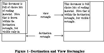 Figure 1–Destination and View Rectangles
You specify both rectangles in the local coordinates of the grafPort. To ensure that the first and last characters in each line are legible in a document window, you may want to inset the destination rectangle at least four pixels from the left and right edges of the grafPort’s portRect (20 pixels from the right edge if there’s a scroll bar or size box).
Edit operations may of course lengthen or shorten the text. If the text becomes too long to be enclosed by the destination rectangle, it’s simply drawn beyond the bottom. In other words, you can think of the destination rectangle as bottomless—its sides determine the beginning and end of each line of text, and its top determines the position of the first line.
Normally, at the right edge of the destination rectangle, the text automatically wraps around to the left edge to begin a new line. A new line also begins where explicitly specified by a Return character in the text. Word wraparound ensures that no word is ever split between lines unless it’s too long to fit entirely on one line, in which case it’s split at the right edge of the destination rectangle.
»The Selection Range
In the text editing environment, a character position is an index into the text, with position 0 corresponding to the first character. The edit record includes fields for character positions that specify the beginning and end of the current selection range, which is the series of characters where the next editing operation will occur. For example, the procedures that cut or copy from the text of an edit record do so to the current selection range.
The selection range, which is inversely highlighted when the window is active, extends from the beginning character position to the end character position. Figure 2 shows a selection range between positions 3 and 8, consisting of five characters (the character at position 8 isn’t included). The end position of a selection range may be 1 greater than the position of the last character of the text, so that the selection range can include the last character.
If the selection range is empty—that is, its beginning and end positions are the same—that position is the text’s insertion point, the position where characters will be inserted. By default, it’s marked with a blinking caret. If, for example, the insertion point is as illustrated in Figure 2 and the inserted characters are “edit ”, the text will read “the edit insertion point”.
Figure 1–Destination and View Rectangles
You specify both rectangles in the local coordinates of the grafPort. To ensure that the first and last characters in each line are legible in a document window, you may want to inset the destination rectangle at least four pixels from the left and right edges of the grafPort’s portRect (20 pixels from the right edge if there’s a scroll bar or size box).
Edit operations may of course lengthen or shorten the text. If the text becomes too long to be enclosed by the destination rectangle, it’s simply drawn beyond the bottom. In other words, you can think of the destination rectangle as bottomless—its sides determine the beginning and end of each line of text, and its top determines the position of the first line.
Normally, at the right edge of the destination rectangle, the text automatically wraps around to the left edge to begin a new line. A new line also begins where explicitly specified by a Return character in the text. Word wraparound ensures that no word is ever split between lines unless it’s too long to fit entirely on one line, in which case it’s split at the right edge of the destination rectangle.
»The Selection Range
In the text editing environment, a character position is an index into the text, with position 0 corresponding to the first character. The edit record includes fields for character positions that specify the beginning and end of the current selection range, which is the series of characters where the next editing operation will occur. For example, the procedures that cut or copy from the text of an edit record do so to the current selection range.
The selection range, which is inversely highlighted when the window is active, extends from the beginning character position to the end character position. Figure 2 shows a selection range between positions 3 and 8, consisting of five characters (the character at position 8 isn’t included). The end position of a selection range may be 1 greater than the position of the last character of the text, so that the selection range can include the last character.
If the selection range is empty—that is, its beginning and end positions are the same—that position is the text’s insertion point, the position where characters will be inserted. By default, it’s marked with a blinking caret. If, for example, the insertion point is as illustrated in Figure 2 and the inserted characters are “edit ”, the text will read “the edit insertion point”.
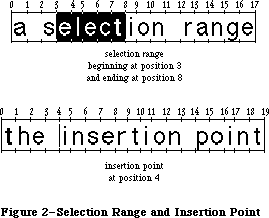 Figure 2–Selection Range and Insertion Point
Note: We use the word caret here generically, to mean a symbol
indicating where something is to be inserted; the specific
symbol is a vertical bar ( | ).
If you call a procedure to insert characters when there’s a selection range of one or more characters rather than an insertion point, the editing procedure automatically deletes the selection range and replaces it with an insertion point before inserting the characters.
»Justification
TextEdit allows you to specify the justification of the lines of text, that is, their horizontal placement with respect to the left and right edges of the destination rectangle. The different types of justification supported by TextEdit are illustrated in Figure 3.
• Left justification aligns the text with the left edge of the
destination rectangle. This is the default type of justification.
• Center justification centers each line of text between the left
and right edges of the destination rectangle.
• Right justification aligns the text with the right edge of the
destination rectangle.
Figure 2–Selection Range and Insertion Point
Note: We use the word caret here generically, to mean a symbol
indicating where something is to be inserted; the specific
symbol is a vertical bar ( | ).
If you call a procedure to insert characters when there’s a selection range of one or more characters rather than an insertion point, the editing procedure automatically deletes the selection range and replaces it with an insertion point before inserting the characters.
»Justification
TextEdit allows you to specify the justification of the lines of text, that is, their horizontal placement with respect to the left and right edges of the destination rectangle. The different types of justification supported by TextEdit are illustrated in Figure 3.
• Left justification aligns the text with the left edge of the
destination rectangle. This is the default type of justification.
• Center justification centers each line of text between the left
and right edges of the destination rectangle.
• Right justification aligns the text with the right edge of the
destination rectangle.
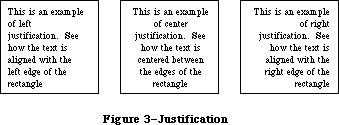 Figure 3–Justification
Note: Trailing spaces on a line are ignored for justification. For
example, “Fred” and “Fred ” will be aligned identically. (Leading
spaces are not ignored.)
TextEdit provides three predefined constants for setting the justification:
CONST teJustLeft = 0;
teJustCenter = 1;
teJustRight = -1;
»The TERec Data Type
The structure of an edit record is given here. Some TextEdit features are available only if you access fields of the edit record directly.
TYPE TERec = RECORD
destRect: Rect; {destination rectangle}
viewRect: Rect; {view rectangle}
selRect: Rect; {used from assembly language}
lineHeight: INTEGER; {for line spacing}
fontAscent: INTEGER; {caret/highlighting position}
selPoint: Point; {used from assembly language}
selStart: INTEGER; {start of selection range}
selEnd: INTEGER; {end of selection range}
active: INTEGER; {used internally}
wordBreak: ProcPtr; {for word break routine}
clikLoop: ProcPtr; {for click loop routine}
clickTime: LONGINT; {used internally}
clickLoc: INTEGER; {used internally}
caretTime: LONGINT; {used internally}
caretState: INTEGER; {used internally}
just: INTEGER; {justification of text}
teLength: INTEGER; {length of text}
hText: Handle; {text to be edited}
recalBack: INTEGER; {used internally}
recalLines: INTEGER; {used internally}
clikStuff: INTEGER; {used internally}
crOnly: INTEGER; {if <0, new line at Return only}
txFont: INTEGER; {text font}
txFace: Style; {character style}
txMode: INTEGER; {pen mode}
txSize: INTEGER; {font size}
inPort: GrafPtr; {grafPort}
highHook: ProcPtr; {used from assembly language}
caretHook: ProcPtr; {used from assembly language}
nLines: INTEGER; {number of lines}
lineStarts: ARRAY[0..16000] OF INTEGER
{positions of line starts}
END;
Warning: Don’t change any of the fields marked “used internally”—these
exist solely for internal use among the TextEdit routines.
The destRect and viewRect fields specify the destination and view rectangles.
The lineHeight and fontAscent fields have to do with the vertical spacing of the lines of text, and where the caret or highlighting of the selection range is drawn relative to the text. The fontAscent field specifies how far above the base line the pen is positioned to begin drawing the caret or highlighting. For single-spaced text, this is the ascent of the text in pixels (the height of the tallest characters in the font from the base line). The lineHeight field specifies the vertical distance from the ascent line of one line of text down to the ascent line of the next. For single-spaced text, this is the same as the font size, but in pixels. The values of the lineHeight and fontAscent fields for single-spaced text are shown in Figure 4. For more information on fonts, see the Font Manager chapter.
Figure 3–Justification
Note: Trailing spaces on a line are ignored for justification. For
example, “Fred” and “Fred ” will be aligned identically. (Leading
spaces are not ignored.)
TextEdit provides three predefined constants for setting the justification:
CONST teJustLeft = 0;
teJustCenter = 1;
teJustRight = -1;
»The TERec Data Type
The structure of an edit record is given here. Some TextEdit features are available only if you access fields of the edit record directly.
TYPE TERec = RECORD
destRect: Rect; {destination rectangle}
viewRect: Rect; {view rectangle}
selRect: Rect; {used from assembly language}
lineHeight: INTEGER; {for line spacing}
fontAscent: INTEGER; {caret/highlighting position}
selPoint: Point; {used from assembly language}
selStart: INTEGER; {start of selection range}
selEnd: INTEGER; {end of selection range}
active: INTEGER; {used internally}
wordBreak: ProcPtr; {for word break routine}
clikLoop: ProcPtr; {for click loop routine}
clickTime: LONGINT; {used internally}
clickLoc: INTEGER; {used internally}
caretTime: LONGINT; {used internally}
caretState: INTEGER; {used internally}
just: INTEGER; {justification of text}
teLength: INTEGER; {length of text}
hText: Handle; {text to be edited}
recalBack: INTEGER; {used internally}
recalLines: INTEGER; {used internally}
clikStuff: INTEGER; {used internally}
crOnly: INTEGER; {if <0, new line at Return only}
txFont: INTEGER; {text font}
txFace: Style; {character style}
txMode: INTEGER; {pen mode}
txSize: INTEGER; {font size}
inPort: GrafPtr; {grafPort}
highHook: ProcPtr; {used from assembly language}
caretHook: ProcPtr; {used from assembly language}
nLines: INTEGER; {number of lines}
lineStarts: ARRAY[0..16000] OF INTEGER
{positions of line starts}
END;
Warning: Don’t change any of the fields marked “used internally”—these
exist solely for internal use among the TextEdit routines.
The destRect and viewRect fields specify the destination and view rectangles.
The lineHeight and fontAscent fields have to do with the vertical spacing of the lines of text, and where the caret or highlighting of the selection range is drawn relative to the text. The fontAscent field specifies how far above the base line the pen is positioned to begin drawing the caret or highlighting. For single-spaced text, this is the ascent of the text in pixels (the height of the tallest characters in the font from the base line). The lineHeight field specifies the vertical distance from the ascent line of one line of text down to the ascent line of the next. For single-spaced text, this is the same as the font size, but in pixels. The values of the lineHeight and fontAscent fields for single-spaced text are shown in Figure 4. For more information on fonts, see the Font Manager chapter.
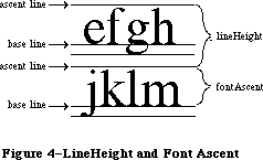 Figure 4–LineHeight and FontAscent
If you want to change the vertical spacing of the text, you should change both the lineHeight and fontAscent fields by the same amount, otherwise the placement of the caret or highlighting of the selection range may not look right. For example, to double the line spacing, add the value of lineHeight to both fields. (This doesn’t change the size of the characters; it affects only the spacing between lines.) If you change the size of the text, you should also change these fields; you can get font measurements you’ll need with the QuickDraw procedure GetFontInfo.
Assembly-language note: The selPoint field (whose assembly-language offset
is named teSelPoint) contains the point selected
with the mouse, in the local coordinates of the
current grafPort. You’ll need this for hit-testing
if you use the routine pointed to by the global
variable TEDoText (see “Advanced Routines” in the
“TextEdit Routines” section).
The selStart and selEnd fields specify the character positions of the beginning and end of the selection range. Remember that character position 0 refers to the first character, and that the end of a selection range can be 1 greater than the position of the last character of the text.
The wordBreak field lets you change TextEdit’s definition of a word, and the clikLoop field lets you implement automatic scrolling. These two fields are described in separate sections below.
The just field specifies the justification of the text. (See “Justification”, above.)
The teLength field contains the number of characters in the text to be edited
(the maximum length is 32K bytes). The hText field is a handle to the text. You can directly change the text of an edit record by changing these two fields.
The crOnly field specifies whether or not text wraps around at the right edge of the destination rectangle, as shown in Figure 5. If crOnly is positive, text does wrap around. If crOnly is negative, text does not wrap around at the edge of the destination rectangle, and new lines are specified explicitly by Return characters only. This is faster than word wraparound, and is useful in an application similar to a programming-language editor, where you may not want a single line of code to be split onto two lines.
Figure 4–LineHeight and FontAscent
If you want to change the vertical spacing of the text, you should change both the lineHeight and fontAscent fields by the same amount, otherwise the placement of the caret or highlighting of the selection range may not look right. For example, to double the line spacing, add the value of lineHeight to both fields. (This doesn’t change the size of the characters; it affects only the spacing between lines.) If you change the size of the text, you should also change these fields; you can get font measurements you’ll need with the QuickDraw procedure GetFontInfo.
Assembly-language note: The selPoint field (whose assembly-language offset
is named teSelPoint) contains the point selected
with the mouse, in the local coordinates of the
current grafPort. You’ll need this for hit-testing
if you use the routine pointed to by the global
variable TEDoText (see “Advanced Routines” in the
“TextEdit Routines” section).
The selStart and selEnd fields specify the character positions of the beginning and end of the selection range. Remember that character position 0 refers to the first character, and that the end of a selection range can be 1 greater than the position of the last character of the text.
The wordBreak field lets you change TextEdit’s definition of a word, and the clikLoop field lets you implement automatic scrolling. These two fields are described in separate sections below.
The just field specifies the justification of the text. (See “Justification”, above.)
The teLength field contains the number of characters in the text to be edited
(the maximum length is 32K bytes). The hText field is a handle to the text. You can directly change the text of an edit record by changing these two fields.
The crOnly field specifies whether or not text wraps around at the right edge of the destination rectangle, as shown in Figure 5. If crOnly is positive, text does wrap around. If crOnly is negative, text does not wrap around at the edge of the destination rectangle, and new lines are specified explicitly by Return characters only. This is faster than word wraparound, and is useful in an application similar to a programming-language editor, where you may not want a single line of code to be split onto two lines.
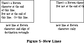 Figure 5–New Lines
The txFont, txFace, txMode, and txSize fields specify the font, character style, pen mode, and font size, respectively, of all the text in the edit record. (See the QuickDraw chapter for details about these characteristics.) If you change one of these values, the entire text of this edit record will have the new characteristics when it’s redrawn. If you change the txSize field, remember to change the lineHeight and fontAscent fields, too.
The inPort field contains a pointer to the grafPort associated with this edit record.
Note: When printing, the inPort field must be set to the Printing Manager’s
grafPort (TPPrPort^.gPort).
Assembly-language note: The highHook and caretHook fields—at the offsets
teHiHook and teCarHook in assembly language—contain
the addresses of routines that deal with text
highlighting and the caret. These routines pass
parameters in registers; the application must save
and restore the registers.
If you store the address of a routine in teHiHook,
that routine will be used instead of the QuickDraw
procedure InvertRect whenever a selection range is
to be highlighted. The routine can destroy the
contents of registers A0, A1, D0, D1, and D2. On
entry, A3 is a pointer to a locked edit record; the
stack contains the rectangle enclosing the text being
highlighted. For example, if you store the address of
the following routine in teHiHook, selection ranges
will be underlined instead of inverted:
UnderHigh
MOVE.L (SP),A0 ;get address of
; rectangle to be
; highlighted
MOVE bottom(A0),top(A0) ;make the top
; coordinate equal
; to the bottom
SUBQ #1,top(A0) ; coordinate - 1
_InverRect ;invert the
; resulting
; rectangle
RTS
The routine whose address is stored in teCarHook acts
exactly the same way as the teHiHook routine, but on
the caret instead of the selection highlighting,
allowing you to change the appearance of the caret.
The routine is called with the stack containing the
rectangle that encloses the caret.
The nLines field contains the number of lines in the text. The lineStarts array contains the character position of the first character in each line. It’s declared to have 16001 elements to comply with Pascal range checking; it’s actually a dynamic data structure having only as many elements as needed. You shouldn’t change the elements of lineStarts.
Note: The extensions to TextEdit described in the following paragraphs were
originally documented in Inside Macintosh, Volume V. As such, this
information refers to the Macintosh SE and Macintosh II ROMs and System
file version 4.1 and later.
In the enhanced version of TextEdit, most fields of the edit record have the same meanings as in the old TextEdit, with the following exceptions:
txSize Used as a flag telling whether the edit record has style
information associated with it:
>0 Old-style edit record; all text set in a single font, size,
and face; all fields (including txSize itself) have their
old, natural meanings.
–1 Edit record has associated style information; the txFont and
txFace fields have new meanings as described below.
txFont, txFace Combine to hold a handle to the associated style record
(see “The Style Record” below). Use new routines
GetStylHandle and SetStylHandle to access or change this
handle in Pascal.
lineHeight Controls whether vertical spacing is fixed or may vary
fontAscent from line to line, depending on specific text styles:
>0 Fixed line height or font ascent, as before.
–1 Line height or font ascent calculated independently for
each line, based on maximum value for any individual style
on that line.
The new routine TEStylNew, which creates a new edit record with style information, sets txSize, lineHeight, and fontAscent to –1, allocates a style record, and stores a handle to the style record in the txFont and txFace fields. The old routine TENew still creates a new edit record without style information, initializing these fields from the current graphics port as before.
»The WordBreak Field
Note: The information on the WordBreak Field described in the following
paragraphs was originally documented in Inside Macintosh, Volume I.
The wordBreak field of an edit record lets you specify the record’s word break routine—the routine that determines the “word” that’s highlighted when the user double-clicks in the text, and the position at which text is wrapped around at the end of a line. The default routine breaks words at any character with an ASCII value of $20 or less (the space character or nonprinting control characters).
The word break routine must have two parameters and return a Boolean value. This is how you would declare one named MyWordBreak:
FUNCTION MyWordBreak (text: Ptr; charPos: INTEGER) : BOOLEAN;
The function should return TRUE to break a word at the character at position charPos in the specified text, or FALSE not to break there. From Pascal, you must call the SetWordBreak procedure to set the wordBreak field so that your routine will be used.
Assembly-language note: You can set this field to point to your own
assembly-language word break routine. The registers
must contain the following:
On entry A0: pointer to text
D0: character position (word)
On exit Z (zero) condition code:
0 to break at specified character
1 not to break there
»The ClikLoop Field
The clikLoop field of an edit record lets you specify a routine that will be called repeatedly (by the TEClick procedure, described below) as long as the mouse button is held down within the text. You can use this to implement the automatic scrolling of text when the user is making a selection and drags the cursor out of the view rectangle.
The click loop routine has no parameters and returns a Boolean value. You could declare a click loop routine named MyClikLoop like this:
FUNCTION MyClikLoop : BOOLEAN;
The function should return TRUE. From Pascal, you must call the SetClikLoop procedure to set the clikLoop field so that TextEdit will call your routine.
Warning: Returning FALSE from your click loop routine tells the TEClick
procedure that the mouse button has been released, which aborts
TEClick.
Assembly-language note: Your routine should set register D0 to 1, and
preserve register D2. (Returning 0 in register
D0 aborts TEClick.)
An automatic scrolling routine might check the mouse location, and call a scrolling routine if the mouse location is outside the view rectangle. (The scrolling routine can be the same routine that the Control Manager function TrackControl calls.) The handle to the current edit record should be kept as a global variable so the scrolling routine can access it.
_______________________________________________________________________________
»The Style Record
Note: The extensions to TextEdit described in the following paragraphs were
originally documented in Inside Macintosh, Volume V. As such, this
information refers to the Macintosh SE and Macintosh II ROMs and System
file version 4.1 and later.
The style record, located via a handle kept in the txFont and txFace fields of the edit record, specifies the styles for the edit record’s text. The text is divided into runs of consecutive characters in the same style, summarized in a table in the runs field of the style record. Each entry in this table gives the starting character position of a run and an index into the style table
(described in the next section). The length of the run is found by subtracting its start position from that of the next entry in the table. A dummy entry at the end of the table delimits the length of the last run; its start position is equal to the overall number of characters in the text, plus 1.
TYPE
TEStyleHandle = ^TEStylePtr;
TEStylePtr = ^TEStyleRec;
TEStyleRec = RECORD
nRuns: INTEGER; {number of style runs}
nStyles: INTEGER; {number of distinct styles }
{ stored in style table}
styleTab: STHandle; {handle to style table}
lhTab: LHHandle; {handle to line-height table}
teRefCon: LONGINT; {reserved for application use}
nullStyle: nullSTHandle; {handle to style set }
{ at null selection}
runs: ARRAY [0..0] OF StyleRun
END;
StyleRun = RECORD
startChar: INTEGER; {starting character position}
styleIndex: INTEGER {index in style table}
END;
Field descriptions
nRuns The nRuns field specifies the number of style runs in the text.
nStyles The nStyles field contains the number of distinct styles used
in the text; this forms the size of the style table.
styleTab The StyleTab field contains a handle to the style table (see
“The Style Table” below).
lhTab The lhTab field contains a handle to the line-height table
(see “The Line-Height Table” below).
teRefCon The teRefCon field is a reference constant for use by applications.
nullStyle The nullStyle field contains a handle to a data structure used
to store the style information for a null selection.
runs The runs field contains an indefinite-length array of style runs.
_______________________________________________________________________________
»The Style Table
The style table contains one entry for each distinct style used in an edit record’s text. The size of the table is given by the nStyles field of the style record. There is no duplication; each style appears exactly once in the table. A reference count tells how many times each style is used within the text.
TYPE
STHandle = ^STPtr;
STPtr = ^TEStyleTable;
TEStyleTable = ARRAY [0..0] OF STElement;
STElement = RECORD
stCount: INTEGER; {number of runs in this style}
stHeight: INTEGER; {line height}
stAscent: INTEGER; {font ascent}
stFont: INTEGER; {font (family) number}
stFace: Style; {character style}
stSize: INTEGER; {size in points}
stColor: RGBColor {absolute (RGB) color}
END;
Field descriptions
stCount The stCount field contains a reference count of character
runs using this style.
stHeight The stHeight field contains the line height for this style,
in points.
stAscent The stAscent field contains the font ascent for this style,
in points.
stFont The stFont field is the font (family) number.
stFace The stFace field is the character style (bold, italic, and
so forth).
stSize The stSize field is the text size in points.
stColor The stColor field is the RGB color; see the Color Manager
chapter for further information.
_______________________________________________________________________________
»The Line-Height Table
The line-height table holds vertical spacing information for an edit record’s text. This table parallels the lineStarts table in the edit record itself. Its length is given by the edit record’s nLines field plus 1 for a dummy entry at the end, just as the line starts array ends with a dummy entry that has the same value as the length of the text. The table’s contents are recalculated whenever the line starts themselves are recalculated with TECalText, or whenever an editing action causes recalibration.
The line-height table is used only if the lineHeight and fontAscent fields in the edit record are negative; positive values in those fields specify fixed vertical spacing, overriding the information in the table.
TYPE
LHHandle = ^LHPtr;
LHPtr = ^LHTable;
LHTable = ARRAY [0..0] OF LHElement;
LHElement = RECORD
lhHeight: INTEGER; {maximum height in line}
lhAscent: INTEGER {maximum ascent in line}
END;
Field descriptions
lhHeight The lhHeight field contains the line height in points;
this is the maximum value for any individual style in a line.
lhAscent The lhAscent field contains the font ascent in points;
this is the maximum value for any individual style in a line.
If you want, you can override TextEdit’s line-height calculation and store your own height and ascent values into the line-height table. Any table entry with the high bit set in the lhHeight field will be used as-is (both height and ascent), overriding whatever values TextEdit would have used. The high bit of lhHeight is masked out to arrive at the true line height, but the high bit of lhAscent is not masked, so you should never set it; the one in lhHeight serves as a flag for both fields. Notice that you can selectively set some lines for yourself and let TextEdit do the rest for you. This technique is intended to be used for static, unchanging text, such as in text boxes; if you use it on text that can change dynamically, be sure to readjust your line-height values whenever the line breaks in the text are recalculated. Otherwise, if new lines are created as a result of a text insertion, their line heights and ascents will be computed by TextEdit.
_______________________________________________________________________________
»The Null-Style Record
The null-style record is used to store the style information for a null selection. If TESetStyle is called when setStart equals setEnd, the input style information is stored in the nullStyle handle. The nStyles field of nullScrap is set to 1, and the style information is stored as the ScrpSTElement. If text is then entered (pasted, inserted, or typed), the style is entered into the runs array, and nStyles is reset to 0. The nStyles field is also reset if the selection offsets are changed (by TEClick, for example).
TYPE
NullSTHandle = ^NullSTPtr;
NullSTPtr = ^NullSTRec;
NullSTRec = RECORD
TEReserved: LONGINT; {reserved for future }
{ expansion}
nullScrap: STScrpHandle {handle to scrap style }
{ table}
END;
Field descriptions
teReserved The teReserved field is reserved for future expansion.
nullScrap The nullScrap field contains a handle to the scrap style table.
_______________________________________________________________________________
»Text Styles
Text style records are used for communicating style information between the application program and the TextEdit routines. They carry the same information as the STElement records in the style table, but without the reference count, line height, and font ascent:
TYPE
TextStyle = RECORD
tsFont: INTEGER; {Font (family) number}
tsFace: Style; {Character style}
tsSize: INTEGER; {Size in points}
tsColor: RGBColor {Absolute (RGB) color}
END;
Field descriptions
tsFont The tsFont field is the font (family) number.
tsFace The tsFace field is the character style (bold, italic, and so forth).
tsSize The tsSize field is the text size in points.
tsColor The tsColor field contains the RGB color; see the Color Manager
chapter for further information.
_______________________________________________________________________________
»The Style Scrap
A new scrap type, 'styl', is used for storing style information in the desk scrap along with the old 'TEXT' scrap. The format of the style scrap is defined by a style scrap record:
TYPE
StScrpHandle = ^StScrpPtr;
StScrpPtr = ^StScrpRec;
StScrpRec = RECORD
scrpNStyles: INTEGER; {number of distinct }
{ styles in scrap}
scrpStyleTab: ScrpSTTable {table of styles for scrap}
END;
Field descriptions
scrpNStyles The scrpNStyles field is the number of distinct styles
used in text; this forms the size of the style table.
scrpSTTable The scrpSTTable is the table of text styles: see the data
structure shown below.
Unlike the main style table for an edit record, the table in the style scrap may contain duplicate elements; the entries in the table correspond one-to-one with the character runs in the text. The scrpStartChar field of each entry gives the starting character position for the run.
The ScrpSTTable is a separate data structure defined for style records in the scrap. Its format is:
TYPE
ScrpSTTable = array [0..0] of ScrpSTElement;
ScrpSTElement = RECORD
scrpStartChar: LONGINT; {offset to start of style}
scrpHeight: INTEGER; {line height}
scrpAscent: INTEGER; {font ascent}
scrpFont: INTEGER; {font (family) number}
scrpFace: Style; {character style}
scrpSize: INTEGER; {size in points}
scrpColor: RGBColor; {absolute (RGB) color}
END;
Field descriptions
scrpStartChar The scrpStartChar field is the offset to the beginning
of a style record in the scrap.
scrpHeight The scrpHeight field contains the line height.
scrpAscent The scrpAscent field contains the font ascent.
scrpFont The scrpFont is the font’s family number.
scrpFace The scrpFace is the character style for the style scrap.
scrpSize The scrpSize field contains the size in points.
scrpColor The scrpColor field contains the RGB color for the style scrap.
_______________________________________________________________________________
»USING TEXTEDIT
_______________________________________________________________________________
Note: The information on Using TextEdit described in the following
paragraphs was originally documented in Inside Macintosh, Volume I.
Before using TextEdit, you must initialize QuickDraw, the Font Manager, and the Window Manager, in that order.
The first TextEdit routine to call is the initialization procedure TEInit. Call TENew to allocate an edit record; it returns a handle to the record. Most of the text editing routines require you to pass this handle as a parameter.
When you’ve finished working with the text of an edit record, you can get a handle to the text as a packed array of characters with the TEGetText function.
Note: To convert text from an edit record to a Pascal string, you can use
the Dialog Manager procedure GetIText, passing it the text handle
from the edit record.
When you’re completely done with an edit record and want to dispose of it, call TEDispose.
To make a blinking caret appear at the insertion point, call the TEIdle procedure as often as possible (at least once each time through the main event loop); if it’s not called often enough, the caret will blink irregularly.
Note: To change the cursor to an I-beam, you can call the Toolbox Utility
function GetCursor and the QuickDraw procedure SetCursor. The resource
ID for the I-beam cursor is defined in the Toolbox Utilities as the
constant iBeamCursor.
When a mouse-down event occurs in the view rectangle (and the window is active) call the TEClick procedure. TEClick controls the placement and highlighting of the selection range, including supporting use of the Shift key to make extended selections.
Key-down, auto-key, and mouse events that pertain to text editing can be handled by several TextEdit procedures:
• TEKey inserts characters and deletes characters backspaced over.
• TECut transfers the selection range to the TextEdit scrap, removing
the selection range from the text.
• TEPaste inserts the contents of the TextEdit scrap. By calling TECut,
changing the insertion point, and then calling TEPaste, you can perform
a “cut and paste” operation, moving text from one place to another.
• TECopy copies the selection range to the TextEdit scrap. By calling
TECopy, changing the insertion point, and then calling TEPaste, you
can make multiple copies of text.
• TEDelete removes the selection range (without transferring it to the
scrap). You can use TEDelete to implement the Clear command.
• TEInsert inserts specified text. You can use this to combine two or
more documents. TEDelete and TEInsert do not modify the scrap, so
they’re useful for implementing the Undo command.
After each editing procedure, TextEdit redraws the text if necessary from the insertion point to the end of the text. You never have to set the selection range or insertion point yourself; TEClick and the editing procedures leave it where it should be. If you want to modify the selection range directly,
however—to highlight an initial default name or value, for example—you can use the TESetSelect procedure.
To implement cutting and pasting of text between different applications, or between applications and desk accessories, you need to transfer the text between the TextEdit scrap (which is a private scrap used only by TextEdit) and the Scrap Manager’s desk scrap. You can do this using the functions TEFromScrap and TEToScrap. (See the Scrap Manager chapter for more information about scrap handling.)
When an update event is reported for a text editing window, call TEUpdate—along with the Window Manager procedures BeginUpdate and EndUpdate—to redraw the text.
Note: After changing any fields of the edit record that affect the
appearance of the text, you should call the Window Manager procedure
InvalRect(hTE^^.viewRect) so that the text will be updated.
The procedures TEActivate and TEDeactivate must be called each time GetNextEvent reports an activate event for a text editing window. TEActivate simply highlights the selection range or displays a caret at the insertion point; TEDeactivate unhighlights the selection range or removes the caret.
To specify the justification of the text, you can use TESetJust. If you change the justification, be sure to call InvalRect so the text will be updated.
To scroll text within the view rectangle, you can use the TEScroll procedure.
Note: The extensions to TextEdit described in the following paragraphs were
originally documented in Inside Macintosh, Volume IV. As such, this
information refers to the 128K ROMs and System file version 3.2 and
later.
Automatic scrolling of text (when the user is making a selection and drags the cursor out of the view rectangle) is now supported by TextEdit.
To enable and disable automatic scrolling, call the procedure TEAutoView. TESelView will, if automatic scrolling is enabled, automatically scroll the selection range into view. TEPinScroll scrolls text within the view rectangle but stops when the last line comes into view.
Note: When enabled, automatic scrolling can occur in response to
TESelView, TEKey, TEPaste, TEDelete, and TESetSelect.
Note: The information on TESetText described in the following
paragraphs was originally documented in Inside Macintosh, Volume I.
The TESetText procedure lets you change the text being edited. For example, if your application has several separate pieces of text that must be edited one at a time, you don’t have to allocate an edit record for each of them. Allocate a single edit record, and then use TESetText to change the text. (This is the method used in dialog boxes.)
Note: TESetText actually makes a copy of the text to be edited. Advanced
programmers can save space by storing a handle to the text in the
hText field of the edit record itself, then calling TECalText to
recalculate the beginning of each line.
If you ever want to draw noneditable text in any given rectangle, you can use the TextBox procedure.
If you’ve written your own word break or click loop routine in Pascal, you must call the SetWordBreak or SetClikLoop procedure to install your routine so TextEdit will use it.
_______________________________________________________________________________
»CUTTING AND PASTING
_______________________________________________________________________________
Note: The extensions to TextEdit described in the following paragraphs were
originally documented in Inside Macintosh, Volume V. As such, this
information refers to the Macintosh SE and Macintosh II ROMs and System
file version 4.1 and later.
For new TextEdit records created using TEStylNew, the routines TECut and TECopy will write both the text and its associated style information directly to the desk scrap, under scrap types 'TEXT' and 'styl', respectively. (For compatibility with existing applications, they also write a handle to the text to the old global TEScrapHandle.) For old TextEdit records, TECopy and TEPaste will work as they did before, copying and pasting via the private TextEdit scrap only.
A new routine, TEStylPaste, reads both text and style back from the desk scrap and pastes them into the document at the current selection range or insertion point. The old TEPaste reads the text only, ignoring any style information found in the scrap; instead it uses the style of the first character in the selection range being replaced, or that of the preceding character if the selection is an insertion point. (TEStylPaste defaults to the same behavior if it doesn’t find a 'styl' entry in the desk scrap.) The old routines TEFromScrap and TEToScrap, for transferring text between the desk and internal scraps, are no longer needed, but are still supported for backward compatibility. The GetStylScrap and TEStylInsert routines can now be used to access the text and style information associated with a given selection without destroying the current contents of the desk scrap.
_______________________________________________________________________________
»TEXTEDIT ROUTINES
_______________________________________________________________________________
Note: The information on TextEdit Routines described in the following
paragraphs was originally documented in Inside Macintosh, Volume I.
Those routines which were added with Styled TextEdit in Volume V
are marked as such.
The Macintosh Plus, Macintosh SE, and Macintosh II versions of TextEdit support all previous TextEdit routines, as well as the new routines described below.
Assembly-language note: All but two of the new routines share a single
trap, _TEDispatch ($A83D). The routines are
distinguished by an integer routine selector
passed on the stack, after the last argument:
TEStylPaste 0
TESetStyle 1
TEReplaceStyle 2
TEGetStyle 3
GetStylHandle 4
SetStylHandle 5
GetStylScrap 6
TEStylInsert 7
TEGetPoint 8
TEGetHeight 9
The Pascal interface supplies the routine selectors
automatically, as do the macros for calling these
routines from assembly language. The remaining two
new TextEdit routines have traps of their own:
_TEStylNew ($A83E) and _TEGetOffset ($A83C).
»Initialization and Allocation
PROCEDURE TEInit;
TEInit initializes TextEdit by allocating a handle for the TextEdit scrap. The scrap is initially empty. Call this procedure once and only once at the beginning of your program.
Note: You should call TEInit even if your application doesn’t use TextEdit,
so that desk accessories and dialog and alert boxes will work correctly.
FUNCTION TENew (destRect,viewRect: Rect) : TEHandle;
TENew allocates a handle for text, creates and initializes an edit record, and returns a handle to the new edit record. DestRect and viewRect are the destination and view rectangles, respectively. Both rectangles are specified in the current grafPort’s coordinates. The destination rectangle must always be at least as wide as the first character drawn (about 20 pixels is a good minimum width). The view rectangle must not be empty (for example, don’t make its right edge less than its left edge if you don’t want any text visible—specify a rectangle off the screen instead).
Call TENew once for every edit record you want allocated. The edit record incorporates the drawing environment of the grafPort, and is initialized for left-justified, single-spaced text with an insertion point at character position 0.
Note: The caret won’t appear until you call TEActivate.
FUNCTION TEStylNew (destRect,viewRect: Rect) : TEHandle; [Styled TextEdit]
The TEStylNew routine creates a new-style edit record with associated style information. It initializes the new record’s txSize, lineHeight, and fontAscent fields to –1; allocates a style record and stores a handle to it in the txFont and txFace fields.
PROCEDURE TEDispose (hTE: TEHandle);
TEDispose releases the memory allocated for the edit record and text specified by hTE. Call this procedure when you’re completely through with an edit record.
_______________________________________________________________________________
»Accessing the Text or Style Information of an Edit Record
PROCEDURE TESetText (text: Ptr; length: LONGINT; hTE: TEHandle);
TESetText incorporates a copy of the specified text into the edit record specified by hTE. The text parameter points to the text, and the length parameter indicates the number of characters in the text. The selection range is set to an insertion point at the end of the text. TESetText doesn’t affect the text drawn in the destination rectangle, so call InvalRect afterward if necessary. TESetText doesn’t dispose of any text currently in the edit record.
FUNCTION TEGetText (hTE: TEHandle) : CharsHandle;
TEGetText returns a handle to the text of the specified edit record. The result is the same as the handle in the hText field of the edit record, but has the CharsHandle data type, which is defined as:
TYPE CharsHandle = ^CharsPtr;
CharsPtr = ^Chars;
Chars = PACKED ARRAY[0..32000] OF CHAR;
You can get the length of the text from the teLength field of the edit record.
PROCEDURE TEGetStyle (offset: INTEGER; VAR theStyle: TextStyle;
VAR lineHeight,fontAscent: INTEGER; hTE: TEHandle);
[Styled TextEdit]
The TEGetStyle procedure returns the style information, including line height and font ascent, associated with a given character in an edit record’s text. For an old-style edit record, it returns the record’s global text characteristics.
PROCEDURE SetStylHandle (theHandle: TEStyleHandle; hTE: TEHandle);
[Styled TextEdit]
The SetStylHandle procedure sets an edit record’s style handle, stored in the txFont and txFace fields. SetStylHandle has no effect on an old-style edit record. Applications should always use SetStylHandle rather than manipulating the fields of the edit record directly.
FUNCTION GetStylHandle (hTE: TEHandle) : TEStyleHandle; [Styled TextEdit]
The GetStylHandle function gets an edit record’s style handle, stored in the txFont and txFace fields. GetStylHandle returns NIL when used with an old-style edit record. Applications should always use this function rather than manipulating the fields of the edit record directly.
Note: See Macintosh Technical Note #207 for information on TEContinuousStyle
and TENumStyles.
X-Ref: Technical Note #207
_______________________________________________________________________________
»Insertion Point and Selection Range
PROCEDURE TEIdle (hTE: TEHandle);
Call TEIdle repeatedly to make a blinking caret appear at the insertion point
(if any) in the text specified by hTE. (The caret appears only when the window containing that text is active, of course.) TextEdit observes a minimum blink interval: No matter how often you call TEIdle, the time between blinks will never be less than the minimum interval.
Note: The initial minimum blink interval setting is 32 ticks. The user
can adjust this setting with the Control Panel desk accessory.
To provide a constant frequency of blinking, you should call TEIdle as often as possible—at least once each time through your main event loop. Call it more than once if your application does an unusually large amount of processing each time through the loop.
Note: You actually need to call TEIdle only when the window containing
the text is active.
PROCEDURE TEClick (pt: Point; extend: BOOLEAN; hTE: TEHandle);
TEClick controls the placement and highlighting of the selection range as determined by mouse events. Call TEClick whenever a mouse-down event occurs in the view rectangle of the edit record specified by hTE, and the window associated with that edit record is active. TEClick keeps control until the mouse button is released. Pt is the mouse location (in local coordinates) at the time the button was pressed, obtainable from the event record.
Note: Use the QuickDraw procedure GlobalToLocal to convert the global
coordinates of the mouse location given in the event record to
the local coordinate system for pt.
Pass TRUE for the extend parameter if the Event Manager indicates that the Shift key was held down at the time of the click (to extend the selection).
TEClick unhighlights the old selection range unless the selection range is being extended. If the mouse moves, meaning that a drag is occurring, TEClick expands or shortens the selection range accordingly. In the case of a double-click, the word under the cursor becomes the selection range; dragging expands or shortens the selection a word at a time.
PROCEDURE TESetSelect (selStart,selEnd: LONGINT; hTE: TEHandle);
TESetSelect sets the selection range to the text between selStart and selEnd in the text specified by hTE. The old selection range is unhighlighted, and the new one is highlighted. If selStart equals selEnd, the selection range is an insertion point, and a caret is displayed.
SelEnd and selStart can range from 0 to 32767. If selEnd is anywhere beyond the last character of the text, the position just past the last character is used.
PROCEDURE TEActivate (hTE: TEHandle);
TEActivate highlights the selection range in the view rectangle of the edit record specified by hTE. If the selection range is an insertion point, it displays a caret there. This procedure should be called every time the Toolbox Event Manager function GetNextEvent reports that the window containing the edit record has become active.
PROCEDURE TEDeactivate (hTE: TEHandle);
TEDeactivate unhighlights the selection range in the view rectangle of the edit record specified by hTE. If the selection range is an insertion point, it removes the caret. This procedure should be called every time the Toolbox Event Manager function GetNextEvent reports that the window containing the edit record has become inactive.
_______________________________________________________________________________
»Editing
PROCEDURE TEKey (key: CHAR; hTE: TEHandle);
TEKey replaces the selection range in the text specified by hTE with the character given by the key parameter, and leaves an insertion point just past the inserted character. If the selection range is an insertion point, TEKey just inserts the character there. If the key parameter contains a Backspace character, the selection range or the character immediately to the left of the insertion point is deleted. TEKey redraws the text as necessary. Call TEKey every time the Toolbox Event Manager function GetNextEvent reports a keyboard event that your application decides should be handled by TextEdit.
Note: TEKey inserts every character passed in the key parameter, so it’s
up to your application to filter out all characters that aren’t
actual text (such as keys typed in conjunction with the Command key).
PROCEDURE TECut (hTE: TEHandle);
TECut removes the selection range from the text specified by hTE and places it in the TextEdit scrap. The text is redrawn as necessary. Anything previously in the scrap is deleted. (See Figure 6.) If the selection range is an insertion point, the scrap is emptied.
Figure 5–New Lines
The txFont, txFace, txMode, and txSize fields specify the font, character style, pen mode, and font size, respectively, of all the text in the edit record. (See the QuickDraw chapter for details about these characteristics.) If you change one of these values, the entire text of this edit record will have the new characteristics when it’s redrawn. If you change the txSize field, remember to change the lineHeight and fontAscent fields, too.
The inPort field contains a pointer to the grafPort associated with this edit record.
Note: When printing, the inPort field must be set to the Printing Manager’s
grafPort (TPPrPort^.gPort).
Assembly-language note: The highHook and caretHook fields—at the offsets
teHiHook and teCarHook in assembly language—contain
the addresses of routines that deal with text
highlighting and the caret. These routines pass
parameters in registers; the application must save
and restore the registers.
If you store the address of a routine in teHiHook,
that routine will be used instead of the QuickDraw
procedure InvertRect whenever a selection range is
to be highlighted. The routine can destroy the
contents of registers A0, A1, D0, D1, and D2. On
entry, A3 is a pointer to a locked edit record; the
stack contains the rectangle enclosing the text being
highlighted. For example, if you store the address of
the following routine in teHiHook, selection ranges
will be underlined instead of inverted:
UnderHigh
MOVE.L (SP),A0 ;get address of
; rectangle to be
; highlighted
MOVE bottom(A0),top(A0) ;make the top
; coordinate equal
; to the bottom
SUBQ #1,top(A0) ; coordinate - 1
_InverRect ;invert the
; resulting
; rectangle
RTS
The routine whose address is stored in teCarHook acts
exactly the same way as the teHiHook routine, but on
the caret instead of the selection highlighting,
allowing you to change the appearance of the caret.
The routine is called with the stack containing the
rectangle that encloses the caret.
The nLines field contains the number of lines in the text. The lineStarts array contains the character position of the first character in each line. It’s declared to have 16001 elements to comply with Pascal range checking; it’s actually a dynamic data structure having only as many elements as needed. You shouldn’t change the elements of lineStarts.
Note: The extensions to TextEdit described in the following paragraphs were
originally documented in Inside Macintosh, Volume V. As such, this
information refers to the Macintosh SE and Macintosh II ROMs and System
file version 4.1 and later.
In the enhanced version of TextEdit, most fields of the edit record have the same meanings as in the old TextEdit, with the following exceptions:
txSize Used as a flag telling whether the edit record has style
information associated with it:
>0 Old-style edit record; all text set in a single font, size,
and face; all fields (including txSize itself) have their
old, natural meanings.
–1 Edit record has associated style information; the txFont and
txFace fields have new meanings as described below.
txFont, txFace Combine to hold a handle to the associated style record
(see “The Style Record” below). Use new routines
GetStylHandle and SetStylHandle to access or change this
handle in Pascal.
lineHeight Controls whether vertical spacing is fixed or may vary
fontAscent from line to line, depending on specific text styles:
>0 Fixed line height or font ascent, as before.
–1 Line height or font ascent calculated independently for
each line, based on maximum value for any individual style
on that line.
The new routine TEStylNew, which creates a new edit record with style information, sets txSize, lineHeight, and fontAscent to –1, allocates a style record, and stores a handle to the style record in the txFont and txFace fields. The old routine TENew still creates a new edit record without style information, initializing these fields from the current graphics port as before.
»The WordBreak Field
Note: The information on the WordBreak Field described in the following
paragraphs was originally documented in Inside Macintosh, Volume I.
The wordBreak field of an edit record lets you specify the record’s word break routine—the routine that determines the “word” that’s highlighted when the user double-clicks in the text, and the position at which text is wrapped around at the end of a line. The default routine breaks words at any character with an ASCII value of $20 or less (the space character or nonprinting control characters).
The word break routine must have two parameters and return a Boolean value. This is how you would declare one named MyWordBreak:
FUNCTION MyWordBreak (text: Ptr; charPos: INTEGER) : BOOLEAN;
The function should return TRUE to break a word at the character at position charPos in the specified text, or FALSE not to break there. From Pascal, you must call the SetWordBreak procedure to set the wordBreak field so that your routine will be used.
Assembly-language note: You can set this field to point to your own
assembly-language word break routine. The registers
must contain the following:
On entry A0: pointer to text
D0: character position (word)
On exit Z (zero) condition code:
0 to break at specified character
1 not to break there
»The ClikLoop Field
The clikLoop field of an edit record lets you specify a routine that will be called repeatedly (by the TEClick procedure, described below) as long as the mouse button is held down within the text. You can use this to implement the automatic scrolling of text when the user is making a selection and drags the cursor out of the view rectangle.
The click loop routine has no parameters and returns a Boolean value. You could declare a click loop routine named MyClikLoop like this:
FUNCTION MyClikLoop : BOOLEAN;
The function should return TRUE. From Pascal, you must call the SetClikLoop procedure to set the clikLoop field so that TextEdit will call your routine.
Warning: Returning FALSE from your click loop routine tells the TEClick
procedure that the mouse button has been released, which aborts
TEClick.
Assembly-language note: Your routine should set register D0 to 1, and
preserve register D2. (Returning 0 in register
D0 aborts TEClick.)
An automatic scrolling routine might check the mouse location, and call a scrolling routine if the mouse location is outside the view rectangle. (The scrolling routine can be the same routine that the Control Manager function TrackControl calls.) The handle to the current edit record should be kept as a global variable so the scrolling routine can access it.
_______________________________________________________________________________
»The Style Record
Note: The extensions to TextEdit described in the following paragraphs were
originally documented in Inside Macintosh, Volume V. As such, this
information refers to the Macintosh SE and Macintosh II ROMs and System
file version 4.1 and later.
The style record, located via a handle kept in the txFont and txFace fields of the edit record, specifies the styles for the edit record’s text. The text is divided into runs of consecutive characters in the same style, summarized in a table in the runs field of the style record. Each entry in this table gives the starting character position of a run and an index into the style table
(described in the next section). The length of the run is found by subtracting its start position from that of the next entry in the table. A dummy entry at the end of the table delimits the length of the last run; its start position is equal to the overall number of characters in the text, plus 1.
TYPE
TEStyleHandle = ^TEStylePtr;
TEStylePtr = ^TEStyleRec;
TEStyleRec = RECORD
nRuns: INTEGER; {number of style runs}
nStyles: INTEGER; {number of distinct styles }
{ stored in style table}
styleTab: STHandle; {handle to style table}
lhTab: LHHandle; {handle to line-height table}
teRefCon: LONGINT; {reserved for application use}
nullStyle: nullSTHandle; {handle to style set }
{ at null selection}
runs: ARRAY [0..0] OF StyleRun
END;
StyleRun = RECORD
startChar: INTEGER; {starting character position}
styleIndex: INTEGER {index in style table}
END;
Field descriptions
nRuns The nRuns field specifies the number of style runs in the text.
nStyles The nStyles field contains the number of distinct styles used
in the text; this forms the size of the style table.
styleTab The StyleTab field contains a handle to the style table (see
“The Style Table” below).
lhTab The lhTab field contains a handle to the line-height table
(see “The Line-Height Table” below).
teRefCon The teRefCon field is a reference constant for use by applications.
nullStyle The nullStyle field contains a handle to a data structure used
to store the style information for a null selection.
runs The runs field contains an indefinite-length array of style runs.
_______________________________________________________________________________
»The Style Table
The style table contains one entry for each distinct style used in an edit record’s text. The size of the table is given by the nStyles field of the style record. There is no duplication; each style appears exactly once in the table. A reference count tells how many times each style is used within the text.
TYPE
STHandle = ^STPtr;
STPtr = ^TEStyleTable;
TEStyleTable = ARRAY [0..0] OF STElement;
STElement = RECORD
stCount: INTEGER; {number of runs in this style}
stHeight: INTEGER; {line height}
stAscent: INTEGER; {font ascent}
stFont: INTEGER; {font (family) number}
stFace: Style; {character style}
stSize: INTEGER; {size in points}
stColor: RGBColor {absolute (RGB) color}
END;
Field descriptions
stCount The stCount field contains a reference count of character
runs using this style.
stHeight The stHeight field contains the line height for this style,
in points.
stAscent The stAscent field contains the font ascent for this style,
in points.
stFont The stFont field is the font (family) number.
stFace The stFace field is the character style (bold, italic, and
so forth).
stSize The stSize field is the text size in points.
stColor The stColor field is the RGB color; see the Color Manager
chapter for further information.
_______________________________________________________________________________
»The Line-Height Table
The line-height table holds vertical spacing information for an edit record’s text. This table parallels the lineStarts table in the edit record itself. Its length is given by the edit record’s nLines field plus 1 for a dummy entry at the end, just as the line starts array ends with a dummy entry that has the same value as the length of the text. The table’s contents are recalculated whenever the line starts themselves are recalculated with TECalText, or whenever an editing action causes recalibration.
The line-height table is used only if the lineHeight and fontAscent fields in the edit record are negative; positive values in those fields specify fixed vertical spacing, overriding the information in the table.
TYPE
LHHandle = ^LHPtr;
LHPtr = ^LHTable;
LHTable = ARRAY [0..0] OF LHElement;
LHElement = RECORD
lhHeight: INTEGER; {maximum height in line}
lhAscent: INTEGER {maximum ascent in line}
END;
Field descriptions
lhHeight The lhHeight field contains the line height in points;
this is the maximum value for any individual style in a line.
lhAscent The lhAscent field contains the font ascent in points;
this is the maximum value for any individual style in a line.
If you want, you can override TextEdit’s line-height calculation and store your own height and ascent values into the line-height table. Any table entry with the high bit set in the lhHeight field will be used as-is (both height and ascent), overriding whatever values TextEdit would have used. The high bit of lhHeight is masked out to arrive at the true line height, but the high bit of lhAscent is not masked, so you should never set it; the one in lhHeight serves as a flag for both fields. Notice that you can selectively set some lines for yourself and let TextEdit do the rest for you. This technique is intended to be used for static, unchanging text, such as in text boxes; if you use it on text that can change dynamically, be sure to readjust your line-height values whenever the line breaks in the text are recalculated. Otherwise, if new lines are created as a result of a text insertion, their line heights and ascents will be computed by TextEdit.
_______________________________________________________________________________
»The Null-Style Record
The null-style record is used to store the style information for a null selection. If TESetStyle is called when setStart equals setEnd, the input style information is stored in the nullStyle handle. The nStyles field of nullScrap is set to 1, and the style information is stored as the ScrpSTElement. If text is then entered (pasted, inserted, or typed), the style is entered into the runs array, and nStyles is reset to 0. The nStyles field is also reset if the selection offsets are changed (by TEClick, for example).
TYPE
NullSTHandle = ^NullSTPtr;
NullSTPtr = ^NullSTRec;
NullSTRec = RECORD
TEReserved: LONGINT; {reserved for future }
{ expansion}
nullScrap: STScrpHandle {handle to scrap style }
{ table}
END;
Field descriptions
teReserved The teReserved field is reserved for future expansion.
nullScrap The nullScrap field contains a handle to the scrap style table.
_______________________________________________________________________________
»Text Styles
Text style records are used for communicating style information between the application program and the TextEdit routines. They carry the same information as the STElement records in the style table, but without the reference count, line height, and font ascent:
TYPE
TextStyle = RECORD
tsFont: INTEGER; {Font (family) number}
tsFace: Style; {Character style}
tsSize: INTEGER; {Size in points}
tsColor: RGBColor {Absolute (RGB) color}
END;
Field descriptions
tsFont The tsFont field is the font (family) number.
tsFace The tsFace field is the character style (bold, italic, and so forth).
tsSize The tsSize field is the text size in points.
tsColor The tsColor field contains the RGB color; see the Color Manager
chapter for further information.
_______________________________________________________________________________
»The Style Scrap
A new scrap type, 'styl', is used for storing style information in the desk scrap along with the old 'TEXT' scrap. The format of the style scrap is defined by a style scrap record:
TYPE
StScrpHandle = ^StScrpPtr;
StScrpPtr = ^StScrpRec;
StScrpRec = RECORD
scrpNStyles: INTEGER; {number of distinct }
{ styles in scrap}
scrpStyleTab: ScrpSTTable {table of styles for scrap}
END;
Field descriptions
scrpNStyles The scrpNStyles field is the number of distinct styles
used in text; this forms the size of the style table.
scrpSTTable The scrpSTTable is the table of text styles: see the data
structure shown below.
Unlike the main style table for an edit record, the table in the style scrap may contain duplicate elements; the entries in the table correspond one-to-one with the character runs in the text. The scrpStartChar field of each entry gives the starting character position for the run.
The ScrpSTTable is a separate data structure defined for style records in the scrap. Its format is:
TYPE
ScrpSTTable = array [0..0] of ScrpSTElement;
ScrpSTElement = RECORD
scrpStartChar: LONGINT; {offset to start of style}
scrpHeight: INTEGER; {line height}
scrpAscent: INTEGER; {font ascent}
scrpFont: INTEGER; {font (family) number}
scrpFace: Style; {character style}
scrpSize: INTEGER; {size in points}
scrpColor: RGBColor; {absolute (RGB) color}
END;
Field descriptions
scrpStartChar The scrpStartChar field is the offset to the beginning
of a style record in the scrap.
scrpHeight The scrpHeight field contains the line height.
scrpAscent The scrpAscent field contains the font ascent.
scrpFont The scrpFont is the font’s family number.
scrpFace The scrpFace is the character style for the style scrap.
scrpSize The scrpSize field contains the size in points.
scrpColor The scrpColor field contains the RGB color for the style scrap.
_______________________________________________________________________________
»USING TEXTEDIT
_______________________________________________________________________________
Note: The information on Using TextEdit described in the following
paragraphs was originally documented in Inside Macintosh, Volume I.
Before using TextEdit, you must initialize QuickDraw, the Font Manager, and the Window Manager, in that order.
The first TextEdit routine to call is the initialization procedure TEInit. Call TENew to allocate an edit record; it returns a handle to the record. Most of the text editing routines require you to pass this handle as a parameter.
When you’ve finished working with the text of an edit record, you can get a handle to the text as a packed array of characters with the TEGetText function.
Note: To convert text from an edit record to a Pascal string, you can use
the Dialog Manager procedure GetIText, passing it the text handle
from the edit record.
When you’re completely done with an edit record and want to dispose of it, call TEDispose.
To make a blinking caret appear at the insertion point, call the TEIdle procedure as often as possible (at least once each time through the main event loop); if it’s not called often enough, the caret will blink irregularly.
Note: To change the cursor to an I-beam, you can call the Toolbox Utility
function GetCursor and the QuickDraw procedure SetCursor. The resource
ID for the I-beam cursor is defined in the Toolbox Utilities as the
constant iBeamCursor.
When a mouse-down event occurs in the view rectangle (and the window is active) call the TEClick procedure. TEClick controls the placement and highlighting of the selection range, including supporting use of the Shift key to make extended selections.
Key-down, auto-key, and mouse events that pertain to text editing can be handled by several TextEdit procedures:
• TEKey inserts characters and deletes characters backspaced over.
• TECut transfers the selection range to the TextEdit scrap, removing
the selection range from the text.
• TEPaste inserts the contents of the TextEdit scrap. By calling TECut,
changing the insertion point, and then calling TEPaste, you can perform
a “cut and paste” operation, moving text from one place to another.
• TECopy copies the selection range to the TextEdit scrap. By calling
TECopy, changing the insertion point, and then calling TEPaste, you
can make multiple copies of text.
• TEDelete removes the selection range (without transferring it to the
scrap). You can use TEDelete to implement the Clear command.
• TEInsert inserts specified text. You can use this to combine two or
more documents. TEDelete and TEInsert do not modify the scrap, so
they’re useful for implementing the Undo command.
After each editing procedure, TextEdit redraws the text if necessary from the insertion point to the end of the text. You never have to set the selection range or insertion point yourself; TEClick and the editing procedures leave it where it should be. If you want to modify the selection range directly,
however—to highlight an initial default name or value, for example—you can use the TESetSelect procedure.
To implement cutting and pasting of text between different applications, or between applications and desk accessories, you need to transfer the text between the TextEdit scrap (which is a private scrap used only by TextEdit) and the Scrap Manager’s desk scrap. You can do this using the functions TEFromScrap and TEToScrap. (See the Scrap Manager chapter for more information about scrap handling.)
When an update event is reported for a text editing window, call TEUpdate—along with the Window Manager procedures BeginUpdate and EndUpdate—to redraw the text.
Note: After changing any fields of the edit record that affect the
appearance of the text, you should call the Window Manager procedure
InvalRect(hTE^^.viewRect) so that the text will be updated.
The procedures TEActivate and TEDeactivate must be called each time GetNextEvent reports an activate event for a text editing window. TEActivate simply highlights the selection range or displays a caret at the insertion point; TEDeactivate unhighlights the selection range or removes the caret.
To specify the justification of the text, you can use TESetJust. If you change the justification, be sure to call InvalRect so the text will be updated.
To scroll text within the view rectangle, you can use the TEScroll procedure.
Note: The extensions to TextEdit described in the following paragraphs were
originally documented in Inside Macintosh, Volume IV. As such, this
information refers to the 128K ROMs and System file version 3.2 and
later.
Automatic scrolling of text (when the user is making a selection and drags the cursor out of the view rectangle) is now supported by TextEdit.
To enable and disable automatic scrolling, call the procedure TEAutoView. TESelView will, if automatic scrolling is enabled, automatically scroll the selection range into view. TEPinScroll scrolls text within the view rectangle but stops when the last line comes into view.
Note: When enabled, automatic scrolling can occur in response to
TESelView, TEKey, TEPaste, TEDelete, and TESetSelect.
Note: The information on TESetText described in the following
paragraphs was originally documented in Inside Macintosh, Volume I.
The TESetText procedure lets you change the text being edited. For example, if your application has several separate pieces of text that must be edited one at a time, you don’t have to allocate an edit record for each of them. Allocate a single edit record, and then use TESetText to change the text. (This is the method used in dialog boxes.)
Note: TESetText actually makes a copy of the text to be edited. Advanced
programmers can save space by storing a handle to the text in the
hText field of the edit record itself, then calling TECalText to
recalculate the beginning of each line.
If you ever want to draw noneditable text in any given rectangle, you can use the TextBox procedure.
If you’ve written your own word break or click loop routine in Pascal, you must call the SetWordBreak or SetClikLoop procedure to install your routine so TextEdit will use it.
_______________________________________________________________________________
»CUTTING AND PASTING
_______________________________________________________________________________
Note: The extensions to TextEdit described in the following paragraphs were
originally documented in Inside Macintosh, Volume V. As such, this
information refers to the Macintosh SE and Macintosh II ROMs and System
file version 4.1 and later.
For new TextEdit records created using TEStylNew, the routines TECut and TECopy will write both the text and its associated style information directly to the desk scrap, under scrap types 'TEXT' and 'styl', respectively. (For compatibility with existing applications, they also write a handle to the text to the old global TEScrapHandle.) For old TextEdit records, TECopy and TEPaste will work as they did before, copying and pasting via the private TextEdit scrap only.
A new routine, TEStylPaste, reads both text and style back from the desk scrap and pastes them into the document at the current selection range or insertion point. The old TEPaste reads the text only, ignoring any style information found in the scrap; instead it uses the style of the first character in the selection range being replaced, or that of the preceding character if the selection is an insertion point. (TEStylPaste defaults to the same behavior if it doesn’t find a 'styl' entry in the desk scrap.) The old routines TEFromScrap and TEToScrap, for transferring text between the desk and internal scraps, are no longer needed, but are still supported for backward compatibility. The GetStylScrap and TEStylInsert routines can now be used to access the text and style information associated with a given selection without destroying the current contents of the desk scrap.
_______________________________________________________________________________
»TEXTEDIT ROUTINES
_______________________________________________________________________________
Note: The information on TextEdit Routines described in the following
paragraphs was originally documented in Inside Macintosh, Volume I.
Those routines which were added with Styled TextEdit in Volume V
are marked as such.
The Macintosh Plus, Macintosh SE, and Macintosh II versions of TextEdit support all previous TextEdit routines, as well as the new routines described below.
Assembly-language note: All but two of the new routines share a single
trap, _TEDispatch ($A83D). The routines are
distinguished by an integer routine selector
passed on the stack, after the last argument:
TEStylPaste 0
TESetStyle 1
TEReplaceStyle 2
TEGetStyle 3
GetStylHandle 4
SetStylHandle 5
GetStylScrap 6
TEStylInsert 7
TEGetPoint 8
TEGetHeight 9
The Pascal interface supplies the routine selectors
automatically, as do the macros for calling these
routines from assembly language. The remaining two
new TextEdit routines have traps of their own:
_TEStylNew ($A83E) and _TEGetOffset ($A83C).
»Initialization and Allocation
PROCEDURE TEInit;
TEInit initializes TextEdit by allocating a handle for the TextEdit scrap. The scrap is initially empty. Call this procedure once and only once at the beginning of your program.
Note: You should call TEInit even if your application doesn’t use TextEdit,
so that desk accessories and dialog and alert boxes will work correctly.
FUNCTION TENew (destRect,viewRect: Rect) : TEHandle;
TENew allocates a handle for text, creates and initializes an edit record, and returns a handle to the new edit record. DestRect and viewRect are the destination and view rectangles, respectively. Both rectangles are specified in the current grafPort’s coordinates. The destination rectangle must always be at least as wide as the first character drawn (about 20 pixels is a good minimum width). The view rectangle must not be empty (for example, don’t make its right edge less than its left edge if you don’t want any text visible—specify a rectangle off the screen instead).
Call TENew once for every edit record you want allocated. The edit record incorporates the drawing environment of the grafPort, and is initialized for left-justified, single-spaced text with an insertion point at character position 0.
Note: The caret won’t appear until you call TEActivate.
FUNCTION TEStylNew (destRect,viewRect: Rect) : TEHandle; [Styled TextEdit]
The TEStylNew routine creates a new-style edit record with associated style information. It initializes the new record’s txSize, lineHeight, and fontAscent fields to –1; allocates a style record and stores a handle to it in the txFont and txFace fields.
PROCEDURE TEDispose (hTE: TEHandle);
TEDispose releases the memory allocated for the edit record and text specified by hTE. Call this procedure when you’re completely through with an edit record.
_______________________________________________________________________________
»Accessing the Text or Style Information of an Edit Record
PROCEDURE TESetText (text: Ptr; length: LONGINT; hTE: TEHandle);
TESetText incorporates a copy of the specified text into the edit record specified by hTE. The text parameter points to the text, and the length parameter indicates the number of characters in the text. The selection range is set to an insertion point at the end of the text. TESetText doesn’t affect the text drawn in the destination rectangle, so call InvalRect afterward if necessary. TESetText doesn’t dispose of any text currently in the edit record.
FUNCTION TEGetText (hTE: TEHandle) : CharsHandle;
TEGetText returns a handle to the text of the specified edit record. The result is the same as the handle in the hText field of the edit record, but has the CharsHandle data type, which is defined as:
TYPE CharsHandle = ^CharsPtr;
CharsPtr = ^Chars;
Chars = PACKED ARRAY[0..32000] OF CHAR;
You can get the length of the text from the teLength field of the edit record.
PROCEDURE TEGetStyle (offset: INTEGER; VAR theStyle: TextStyle;
VAR lineHeight,fontAscent: INTEGER; hTE: TEHandle);
[Styled TextEdit]
The TEGetStyle procedure returns the style information, including line height and font ascent, associated with a given character in an edit record’s text. For an old-style edit record, it returns the record’s global text characteristics.
PROCEDURE SetStylHandle (theHandle: TEStyleHandle; hTE: TEHandle);
[Styled TextEdit]
The SetStylHandle procedure sets an edit record’s style handle, stored in the txFont and txFace fields. SetStylHandle has no effect on an old-style edit record. Applications should always use SetStylHandle rather than manipulating the fields of the edit record directly.
FUNCTION GetStylHandle (hTE: TEHandle) : TEStyleHandle; [Styled TextEdit]
The GetStylHandle function gets an edit record’s style handle, stored in the txFont and txFace fields. GetStylHandle returns NIL when used with an old-style edit record. Applications should always use this function rather than manipulating the fields of the edit record directly.
Note: See Macintosh Technical Note #207 for information on TEContinuousStyle
and TENumStyles.
X-Ref: Technical Note #207
_______________________________________________________________________________
»Insertion Point and Selection Range
PROCEDURE TEIdle (hTE: TEHandle);
Call TEIdle repeatedly to make a blinking caret appear at the insertion point
(if any) in the text specified by hTE. (The caret appears only when the window containing that text is active, of course.) TextEdit observes a minimum blink interval: No matter how often you call TEIdle, the time between blinks will never be less than the minimum interval.
Note: The initial minimum blink interval setting is 32 ticks. The user
can adjust this setting with the Control Panel desk accessory.
To provide a constant frequency of blinking, you should call TEIdle as often as possible—at least once each time through your main event loop. Call it more than once if your application does an unusually large amount of processing each time through the loop.
Note: You actually need to call TEIdle only when the window containing
the text is active.
PROCEDURE TEClick (pt: Point; extend: BOOLEAN; hTE: TEHandle);
TEClick controls the placement and highlighting of the selection range as determined by mouse events. Call TEClick whenever a mouse-down event occurs in the view rectangle of the edit record specified by hTE, and the window associated with that edit record is active. TEClick keeps control until the mouse button is released. Pt is the mouse location (in local coordinates) at the time the button was pressed, obtainable from the event record.
Note: Use the QuickDraw procedure GlobalToLocal to convert the global
coordinates of the mouse location given in the event record to
the local coordinate system for pt.
Pass TRUE for the extend parameter if the Event Manager indicates that the Shift key was held down at the time of the click (to extend the selection).
TEClick unhighlights the old selection range unless the selection range is being extended. If the mouse moves, meaning that a drag is occurring, TEClick expands or shortens the selection range accordingly. In the case of a double-click, the word under the cursor becomes the selection range; dragging expands or shortens the selection a word at a time.
PROCEDURE TESetSelect (selStart,selEnd: LONGINT; hTE: TEHandle);
TESetSelect sets the selection range to the text between selStart and selEnd in the text specified by hTE. The old selection range is unhighlighted, and the new one is highlighted. If selStart equals selEnd, the selection range is an insertion point, and a caret is displayed.
SelEnd and selStart can range from 0 to 32767. If selEnd is anywhere beyond the last character of the text, the position just past the last character is used.
PROCEDURE TEActivate (hTE: TEHandle);
TEActivate highlights the selection range in the view rectangle of the edit record specified by hTE. If the selection range is an insertion point, it displays a caret there. This procedure should be called every time the Toolbox Event Manager function GetNextEvent reports that the window containing the edit record has become active.
PROCEDURE TEDeactivate (hTE: TEHandle);
TEDeactivate unhighlights the selection range in the view rectangle of the edit record specified by hTE. If the selection range is an insertion point, it removes the caret. This procedure should be called every time the Toolbox Event Manager function GetNextEvent reports that the window containing the edit record has become inactive.
_______________________________________________________________________________
»Editing
PROCEDURE TEKey (key: CHAR; hTE: TEHandle);
TEKey replaces the selection range in the text specified by hTE with the character given by the key parameter, and leaves an insertion point just past the inserted character. If the selection range is an insertion point, TEKey just inserts the character there. If the key parameter contains a Backspace character, the selection range or the character immediately to the left of the insertion point is deleted. TEKey redraws the text as necessary. Call TEKey every time the Toolbox Event Manager function GetNextEvent reports a keyboard event that your application decides should be handled by TextEdit.
Note: TEKey inserts every character passed in the key parameter, so it’s
up to your application to filter out all characters that aren’t
actual text (such as keys typed in conjunction with the Command key).
PROCEDURE TECut (hTE: TEHandle);
TECut removes the selection range from the text specified by hTE and places it in the TextEdit scrap. The text is redrawn as necessary. Anything previously in the scrap is deleted. (See Figure 6.) If the selection range is an insertion point, the scrap is emptied.
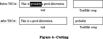 Figure 6–Cutting
PROCEDURE TECopy (hTE: TEHandle);
TECopy copies the selection range from the text specified by hTE into the TextEdit scrap. Anything previously in the scrap is deleted. The selection range is not deleted. If the selection range is an insertion point, the scrap is emptied.
PROCEDURE TEPaste (hTE: TEHandle);
TEPaste replaces the selection range in the text specified by hTE with the contents of the TextEdit scrap, and leaves an insertion point just past the inserted text. (See Figure 7.) The text is redrawn as necessary. If the scrap is empty, the selection range is deleted. If the selection range is an insertion point, TEPaste just inserts the scrap there.
Figure 6–Cutting
PROCEDURE TECopy (hTE: TEHandle);
TECopy copies the selection range from the text specified by hTE into the TextEdit scrap. Anything previously in the scrap is deleted. The selection range is not deleted. If the selection range is an insertion point, the scrap is emptied.
PROCEDURE TEPaste (hTE: TEHandle);
TEPaste replaces the selection range in the text specified by hTE with the contents of the TextEdit scrap, and leaves an insertion point just past the inserted text. (See Figure 7.) The text is redrawn as necessary. If the scrap is empty, the selection range is deleted. If the selection range is an insertion point, TEPaste just inserts the scrap there.
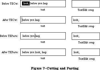 Figure 7–Cutting and Pasting
PROCEDURE TEStylPaste (hTE: TEHandle); [Styled TextEdit]
The TEStylPaste procedure pastes text from the desk scrap into the edit
record’s text at the current insertion point or replaces the current selection. The text is styled according to the style information found in the desk scrap; if there is none, it is given the same style as the first character of the replaced selection (or that of the preceding character if the selection is an insertion point). In an old-style edit record, just the text is pasted without its accompanying style.
PROCEDURE TEDelete (hTE: TEHandle);
TEDelete removes the selection range from the text specified by hTE, and redraws the text as necessary. TEDelete is the same as TECut (above) except that it doesn’t transfer the selection range to the scrap. If the selection range is an insertion point, nothing happens.
PROCEDURE TEInsert (text: Ptr; length: LONGINT; hTE: TEHandle);
TEInsert takes the specified text and inserts it just before the selection range into the text indicated by hTE, redrawing the text as necessary. The text parameter points to the text to be inserted, and the length parameter indicates the number of characters to be inserted. TEInsert doesn’t affect either the current selection range or the scrap.
PROCEDURE TEStylInsert (text: Ptr; length: LONGINT; hST: stScrpHandle;
hTE: TEHandle); [Styled TextEdit]
The TEStylInsert procedure takes the specified text and inserts it just before the selection range into the text indicated by hTE, redrawing the text as necessary. If hST is not NIL and hTE is a TextEdit record created using TEStylNew, the style information indicated by hST will also be inserted to correspond with the inserted text. When hST is NIL and/or hTE has not been created using TEStylNew, there is no difference between this procedure and TEInsert. TEStylInsert does not affect either the current selection range or the scrap.
PROCEDURE TEReplaceStyle (mode: INTEGER; oldStyle,newStyle: TextStyle;
redraw: BOOLEAN; hTE: TEHandle); [Styled TextEdit]
The TEReplaceStyle procedure replaces the style specified by oldStyle with that given by newStyle within the current selection. (It has no effect on an old-style edit record.) The mode parameter takes the same values as TESetStyle
(above), except that addSize has no meaning here. All styles for which the combination of attributes designated by mode have the values given by oldStyle are changed to have the corresponding values from newStyle instead. Style changes are made directly to the style-table elements within the table itself. If mode = doAll, newStyle simply replaces oldStyle outright.
PROCEDURE TESetStyle (mode: INTEGER; newStyle: TextStyle; redraw: BOOLEAN;
hTE: TEHandle); [Styled TextEdit]
The TESetStyle procedure sets the style of the current selection to that specified by newStyle. ( It has no effect on an old-style edit record.) The mode parameter controls which style attributes to set; it may be any additive combination of the following constants:
CONST
doFont = 1; {set font (family) number}
doFace = 2; {set character style}
doSize = 4; {set type size}
doColor = 8; {set color}
doAll = 15; {set all attributes}
addSize = 16; {adjust type size}
In the last case (addSize), the value of newStyle.tsSize is added to all type sizes within the current selection instead of replacing them; this value may be either positive or negative. (If present, addSize overrides doSize.) If redraw = TRUE, the affected text will be redrawn in the new style.
_______________________________________________________________________________
»Text Display and Scrolling
PROCEDURE TESetJust (just: INTEGER, hTE: TEHandle);
TESetJust sets the justification of the text specified by hTE to just. TextEdit provides three predefined constants for setting justification:
CONST teJustLeft = 0;
teJustCenter = 1;
teJustRight = -1;
By default, text is left-justified. If you change the justification, call InvalRect after TESetJust, so the text will be redrawn with the new justification.
PROCEDURE TEUpdate (rUpdate: Rect; hTE: TEHandle);
TEUpdate draws the text specified by hTE within the rectangle specified by rUpdate (given in the coordinates of the current grafPort). Call TEUpdate every time the Toolbox Event Manager function GetNextEvent reports an update event for a text editing window—after you call the Window Manager procedure BeginUpdate, and before you call EndUpdate.
Normally you’ll do the following when an update event occurs:
BeginUpdate(myWindow);
EraseRect(myWindow^.portRect);
TEUpdate(myWindow^.portRect,hTE);
EndUpdate(myWindow)
If you don’t include the EraseRect call, the caret may sometimes remain visible when the window is deactivated.
PROCEDURE TextBox (text: Ptr; length: LONGINT; box: Rect; just: INTEGER);
TextBox draws the specified text in the rectangle indicated by the box parameter, with justification just. (See “Justification” under “Edit Records”.) The text parameter points to the text, and the length parameter indicates the number of characters to draw. The rectangle is specified in local coordinates, and must be at least as wide as the first character drawn (a good rule of thumb is to make it at least 20 pixels wide). TextBox creates its own edit record, which it deletes when it’s finished with it, so the text it draws cannot be edited.
For example:
str := 'String in a box';
SetRect(r,100,100,200,200);
TextBox(POINTER(ORD(@str)+1),LENGTH(str),r,teJustCenter);
FrameRect(r)
Because Pascal strings start with a length byte, you must advance the pointer one position past the beginning of the string to point to the start of the text.
PROCEDURE TEScroll (dh,dv: INTEGER; hTE: TEHandle);
TEScroll scrolls the text within the view rectangle of the specified edit record by the number of pixels specified in the dh and dv parameters. The edit record is specified by the hTE parameter. Positive dh and dv values move the text right and down, respectively, and negative values move the text left and up. For example,
TEScroll(0,-hTE^^.lineHeight,hTE)
scrolls the text up one line. Remember that you scroll text up when the user clicks in the scroll arrow pointing down. The destination rectangle is offset by the amount you scroll.
Note: To implement automatic scrolling, you store the address of a routine
in the clikLoop field of the edit record, as described above under
“The TERec Data Type”.
PROCEDURE TESelView (hTE: TEHandle); [Volume IV addition]
If automatic scrolling has been enabled (by a call to TEAutoView, described below), TESelView makes sure that the selection range is visible, scrolling it into the view rectangle if necessary. If automatic scrolling is disabled, TESelView does nothing.
Note: The top left of the insertion is scrolled into view; if text is
being displayed in a rectangle that’s not tall enough, automatic
scrolling could cause the text to jump up and down at times.
PROCEDURE TEPinScroll (dh,dv: INTEGER; hTE: TEHandle); [Volume IV addition]
TEPinScroll is similar to TEScroll except that it stops scrolling when the last line scrolls into the view rectangle.
PROCEDURE TEAutoView (auto: BOOLEAN; hTE: TEHandle); [Volume IV addition]
TEAutoView enables and disables automatic scrolling of text in the edit record specified by hTe. If the auto parameter is FALSE, automatic scrolling is disabled and calling TESelView has no effect.
_______________________________________________________________________________
»Scrap Handling
The TEFromScrap and TEToScrap functions return a result code of type OSErr
(defined as INTEGER in the Operating System Utilities) indicating whether an error occurred. If no error occurred, they return the result code
CONST noErr = 0; {no error}
Otherwise, they return an Operating System result code indicating an error.
(See Appendix A for a list of all result codes.)
FUNCTION TEFromScrap : OSErr; [Not in ROM]
TEFromScrap copies the desk scrap to the TextEdit scrap. If no error occurs, it returns the result code noErr; otherwise, it returns an appropriate Operating System result code.
Assembly-language note: From assembly language, you can store a handle to
the desk scrap in the global variable TEScrpHandle,
and the size of the desk scrap in the global
variable TEScrpLength; you can get these values
with the Scrap Manager function InfoScrap.
FUNCTION TEToScrap : OSErr; [Not in ROM]
TEToScrap copies the TextEdit scrap to the desk scrap. If no error occurs, it returns the result code noErr; otherwise, it returns an appropriate Operating System result code.
Warning: You must call the Scrap Manager function ZeroScrap to initialize
the desk scrap or clear its previous contents before calling
TEToScrap.
Assembly-language note: From assembly language, you can copy the TextEdit
scrap to the desk scrap by calling the Scrap Manager
function PutScrap; you can get the values you need
from the global variables TEScrpHandle and
TEScrpLength.
FUNCTION TEScrapHandle : Handle; [Not in ROM]
TEScrapHandle returns a handle to the TextEdit scrap.
Assembly-language note: The global variable TEScrpHandle contains a handle
to the TextEdit scrap.
FUNCTION TEGetScrapLen : LONGINT; [Not in ROM]
TEGetScrapLen returns the size of the TextEdit scrap in bytes.
Assembly-language note: The global variable TEScrpLength contains the size
of the TextEdit scrap in bytes.
PROCEDURE TESetScrapLen (length: LONGINT); [Not in ROM]
TESetScrapLen sets the size of the TextEdit scrap to the given number of bytes.
Assembly-language note: From assembly language, you can set the global
variable TEScrpLength.
FUNCTION GetStylScrap (hTE: TEHandle) : StScrpHandle; [Styled TextEdit]
The GetStylScrap routine allocates a block of type StScrpRec and copies the style information associated with the current selection into it. This is the same as TECopy, except that no action is performed on the text, and the handle to the 'styl' scrap is output in this case. Unlike TECopy, the StScrpRec is not copied to the desk scrap.
GetStylScrap will return a NIL value if called with an old style TEHandle, or if the selection is NIL (stylStart equals stylEnd).
Note: See Macintosh Technical Note #207 for information on SetStylScrap.
X-Ref: Technical Note #207
_______________________________________________________________________________
»Advanced Routines
PROCEDURE TECalText (hTE: TEHandle);
TECalText recalculates the beginnings of all lines of text in the edit record specified by hTE, updating elements of the lineStarts array. Call TECalText if you’ve changed the destination rectangle, the hText field, or any other field that affects the number of characters per line.
Note: There are two ways to specify text to be edited. The easiest method
is to use TESetText, which takes an existing edit record, creates a
copy of the specified text, and stores a handle to the copy in the
edit record. You can instead directly change the hText field of the
edit record, and then call TECalText to recalculate the lineStarts
array to match the new text. If you have a lot of text, you can use
the latter method to save space.
Assembly-language note: The global variable TERecal contains the address
of the routine called by TECalText to recalculate
the line starts and set the first and last characters
that need to be redrawn. The registers contain the
following:
On entry A3: pointer to the locked edit record
D7: change in the length of the
record (word)
On exit D2: line start of the line containing
the first character to be
redrawn (word)
D3: position of first character to be
redrawn (word)
D4: position of last character to be
redrawn (word)
Assembly-language note: The global variable TEDoText contains the address
of a multi-purpose text editing routine that advanced
programmers may find useful. It lets you display,
highlight, and hit-test characters, and position the
pen to draw the caret. “Hit-test” means decide where
to place the insertion point when the user clicks the
mouse button; the point selected with the mouse is in
the teSelPoint field. The registers contain the
following:
On entry A3: pointer to the locked edit record
D3: position of first character to be
redrawn (word)
D4: position of last character to be
redrawn (word)
D7: (word) 0 to hit-test a character
1 to highlight the selection
range
–1 to display the text
–2 to position the pen to
draw the caret
On exit A0: pointer to current grafPort
D0: if hit-testing, character position
or –1 for none (word)
FUNCTION TEGetOffset (pt: Point; hTE: TEHandle) : INTEGER; [Styled TextEdit]
The TEGetOffset routine finds the character offset in an edit record’s text corresponding to the given point. TEGetOffset works for both old-style and
new-style edit records.
FUNCTION TEGetPoint (offset: INTEGER; hTE: TEHandle) : POINT; [Styled TextEdit]
The TEGetPoint routine returns the point corresponding to the given offset into the text. The point returned is to the bottom (baseline) left of the character at the specified offset. TEGetPoint works for both old- and new-style edit records.
FUNCTION TEGetHeight (endLine, startLine: LONGINT; hTE: TEHandle) : INTEGER;
[Styled TextEdit]
The TEGetHeight routine returns the total height of all the lines in the text between and including startLine and endLine. TEGetHeight works for both old- and new-style edit records.
PROCEDURE SetWordBreak (wBrkProc: ProcPtr; hTE: TEHandle); [Not in ROM]
SetWordBreak installs in the wordBreak field of the specified edit record a special routine that calls the word break routine pointed to by wBrkProc. The specified word break routine will be called instead of TextEdit’s default routine, as described under “The WordBreak Field” in the “Edit Records” section.
Assembly-language note: From assembly language you don’t need this
procedure; just set the field of the edit record
to point to your word break routine.
PROCEDURE SetClikLoop (clikProc: ProcPtr; hTE: TEHandle); [Not in ROM]
SetClikLoop installs in the clikLoop field of the specified edit record a special routine that calls the click loop routine pointed to by clikProc. The specified click loop routine will be called repeatedly as long as the user holds down the mouse button within the text, as described above under “The ClikLoop Field” in the “Edit Records” section.
Assembly-language note: Like SetWordBreak, this procedure isn’t necessary
from assembly language; just set the field of the
edit record to point to your click loop routine.
Note: See Macintosh Technical Note #207 for information on TECustomHook,
which provides TEEOLHook, TEWidthHook, TEDrawHook, and TEHitTestHook.
X-Ref: Technical Note #207
_______________________________________________________________________________
»SUMMARY OF TEXTEDIT
_______________________________________________________________________________
Constants
CONST
teJustLeft = 0; { Text justification }
teJustCenter = 1;
teJustRight = -1;
{[Styled TextEdit]}
doFont = 1; {set font (family) number}
doFace = 2; {set character style}
doSize = 4; {set type size}
doColor = 8; {set color}
doAll = 15; {set all attributes}
addSize = 16; {adjust type size}
_______________________________________________________________________________
Data Types
TYPE
TEHandle = ^TEPtr;
TEPtr = ^TERec;
TERec = RECORD
destRect: Rect; {destination rectangle}
viewRect: Rect; {view rectangle}
selRect: Rect; {used from assembly language}
lineHeight: INTEGER; {for line spacing}
fontAscent: INTEGER; {caret/highlighting position}
selPoint: Point; {used from assembly language}
selStart: INTEGER; {start of selection range}
selEnd: INTEGER; {end of selection range}
active: INTEGER; {used internally}
wordBreak: ProcPtr; {for word break routine}
clikLoop: ProcPtr; {for click loop routine}
clickTime: LONGINT; {used internally}
clickLoc: INTEGER; {used internally}
caretTime: LONGINT; {used internally}
caretState: INTEGER; {used internally}
just: INTEGER; {justification of text}
teLength: INTEGER; {length of text}
hText: Handle; {text to be edited}
recalBack: INTEGER; {used internally}
recalLines: INTEGER; {used internally}
clikStuff: INTEGER; {used internally}
crOnly: INTEGER; {if <0, new line at Return only}
txFont: INTEGER; {text font}
txFace: Style; {character style}
txMode: INTEGER; {pen mode}
txSize: INTEGER; {font size}
inPort: GrafPtr; {grafPort}
highHook: ProcPtr; {used from assembly language}
caretHook: ProcPtr; {used from assembly language}
nLines: INTEGER; {number of lines}
lineStarts: ARRAY[0..16000] OF INTEGER
{positions of line starts}
END;
CharsHandle = ^CharsPtr;
CharsPtr = ^Chars;
Chars = PACKED ARRAY[0..32000] OF CHAR;
{[Styled TextEdit]}
TEStyleHandle = ^TEStylePtr;
TEStylePtr = ^TEStyleRec;
TEStyleRec = RECORD
nRuns: INTEGER; {number of style runs}
nStyles: INTEGER; {number of distinct styles }
{ stored in style table}
styleTab: STHandle; {handle to style table}
lhTab: LHHandle; {handle to line-height table}
teRefCon: LONGINT; {reserved for application use}
nullStyle: nullSTHandle; {handle to style set }
{ at null selection}
runs: ARRAY [0..0] OF StyleRun
END;
StyleRun = RECORD
startChar: INTEGER; {starting character position}
styleIndex: INTEGER {index in style table}
END;
STHandle = ^STPtr;
STPtr = ^TEStyleTable;
TEStyleTable = ARRAY [0..0] OF STElement;
STElement = RECORD
stCount: INTEGER; {number of runs in this style}
stHeight: INTEGER; {line height}
stAscent: INTEGER; {font ascent}
stFont: INTEGER; {font (family) number}
stFace: Style; {character style}
stSize: INTEGER; {size in points}
stColor: RGBColor {absolute (RGB) color}
END;
LHHandle = ^LHPtr;
LHPtr = ^LHTable;
LHTable = ARRAY [0..0] OF LHElement;
LHElement = RECORD
lhHeight: INTEGER; {maximum height in line}
lhAscent: INTEGER {maximum ascent in line}
END;
NullSTHandle = ^NullSTPtr;
NullSTPtr = ^NullSTRec;
NullSTRec = RECORD
TEReserved: LONGINT; {reserved for future }
{ expansion}
nullScrap: STScrpHandle {handle to scrap style }
{ table}
END;
TextStyle = RECORD
tsFont: INTEGER; {Font (family) number}
tsFace: Style; {Character style}
tsSize: INTEGER; {Size in points}
tsColor: RGBColor {Absolute (RGB) color}
END;
StScrpHandle = ^StScrpPtr;
StScrpPtr = ^StScrpRec;
StScrpRec = RECORD
scrpNStyles: INTEGER; {number of distinct }
{ styles in scrap}
scrpStyleTab: ScrpSTTable {table of styles for scrap}
END;
ScrpSTTable = array [0..0] of ScrpSTElement;
ScrpSTElement = RECORD
scrpStartChar: LONGINT; {offset to start of style}
scrpHeight: INTEGER; {line height}
scrpAscent: INTEGER; {font ascent}
scrpFont: INTEGER; {font (family) number}
scrpFace: Style; {character style}
scrpSize: INTEGER; {size in points}
scrpColor: RGBColor; {absolute (RGB) color}
END;
_______________________________________________________________________________
Routines
Initialization and Allocation
PROCEDURE TEInit;
FUNCTION TENew (destRect,viewRect: Rect) : TEHandle;
FUNCTION TEStylNew (destRect,viewRect: Rect) : TEHandle; [Styled TextEdit]
PROCEDURE TEDispose (hTE: TEHandle);
Accessing the Text or Style Information of an Edit Record
PROCEDURE TESetText (text: Ptr; length: LONGINT; hTE: TEHandle);
FUNCTION TEGetText (hTE: TEHandle) : CharsHandle;
[Styled TextEdit additions]
PROCEDURE TEGetStyle (offset: INTEGER; VAR theStyle: TextStyle;
VAR lineHeight,fontAscent: INTEGER; hTE: TEHandle);
PROCEDURE SetStylHandle (theHandle: TEStyleHandle; hTE: TEHandle);
FUNCTION GetStylHandle (hTE: TEHandle) : TEStyleHandle;
Insertion Point and Selection Range
PROCEDURE TEIdle (hTE: TEHandle);
PROCEDURE TEClick (pt: Point; extend: BOOLEAN; hTE: TEHandle);
PROCEDURE TESetSelect (selStart,selEnd: LONGINT; hTE: TEHandle);
PROCEDURE TEActivate (hTE: TEHandle);
PROCEDURE TEDeactivate (hTE: TEHandle);
Editing
PROCEDURE TEKey (key: CHAR; hTE: TEHandle);
PROCEDURE TECut (hTE: TEHandle);
PROCEDURE TECopy (hTE: TEHandle);
PROCEDURE TEPaste (hTE: TEHandle);
PROCEDURE TEStylPaste (hTE: TEHandle); [Styled TextEdit]
PROCEDURE TEDelete (hTE: TEHandle);
PROCEDURE TEInsert (text: Ptr; length: LONGINT; hTE: TEHandle);
PROCEDURE TEStylInsert (text: Ptr; length: LONGINT; hST: stScrpHandle;
hTE: TEHandle); [Styled TextEdit]
PROCEDURE TEReplaceStyle (mode: INTEGER; oldStyle,newStyle: TextStyle;
redraw: BOOLEAN; hTE: TEHandle); [Styled TextEdit]
PROCEDURE TESetStyle (mode: INTEGER; newStyle: TextStyle; redraw: BOOLEAN;
hTE: TEHandle); [Styled TextEdit]
Text Display and Scrolling
PROCEDURE TESetJust (just: INTEGER; hTE: TEHandle);
PROCEDURE TEUpdate (rUpdate: Rect; hTE: TEHandle);
PROCEDURE TextBox (text: Ptr; length: LONGINT; box: Rect;
just: INTEGER);
PROCEDURE TEScroll (dh,dv: INTEGER; hTE: TEHandle);
[Volume IV additions]
PROCEDURE TESelView (hTE: TEHandle);
PROCEDURE TEPinScroll (dh,dv: INTEGER; hTE: TEHandle);
PROCEDURE TEAutoView (auto: BOOLEAN; hTE: TEHandle);
Scrap Handling [Not in ROM]
FUNCTION TEFromScrap : OSErr;
FUNCTION TEToScrap : OSErr;
FUNCTION TEScrapHandle : Handle;
FUNCTION TEGetScrapLen : LONGINT;
PROCEDURE TESetScrapLen : (length: LONGINT);
FUNCTION GetStylScrap (hTE: TEHandle) : StScrpHandle; [Styled TextEdit]
Advanced Routines
PROCEDURE TECalText (hTE: TEHandle);
FUNCTION TEGetOffset (pt: Point; hTE: TEHandle) : INTEGER; [Styled TextEdit]
FUNCTION TEGetPoint (offset: INTEGER;
hTE: TEHandle) : POINT; [Styled TextEdit]
FUNCTION TEGetHeight (endLine, startLine: LONGINT;
hTE: TEHandle) : INTEGER; [Styled TextEdit]
PROCEDURE SetWordBreak (wBrkProc: ProcPtr; hTE: TEHandle); [Not in ROM]
PROCEDURE SetClikLoop (clikProc: ProcPtr; hTE: TEHandle); [Not in ROM]
_______________________________________________________________________________
Word Break Routine
FUNCTION MyWordBreak (text: Ptr; charPos: INTEGER) : BOOLEAN;
_______________________________________________________________________________
Click Loop Routine
FUNCTION MyClikLoop : BOOLEAN;
_______________________________________________________________________________
Assembly-Language Information
Constants
Text justification
teJustLeft .EQU 0
teJustCenter .EQU 1
teJustRight .EQU –1
[Styled TextEdit additions]
Set/Replace style modes
fontBit EQU 0 ;set font
faceBit EQU 1 ;set face
sizeBit EQU 2 ;set size
clrBit EQU 3 ;set color
addSizeBit EQU 4 ;add size mode
teStylesH EQU teFont ;replaces teFont/teFace
Offsets into TEStyleRec
nRuns EQU 0 ;[integer] # of entries in styleStarts array
nStyles EQU 2 ;[integer] # of distinct styles
styleTab EQU 4 ;[STHandle] handle to distinct styles
lhTab EQU 8 ;[LHHandle] handle to line heights
teRefCon EQU 12 ;[longint] reserved
nullStyle EQU 16 ;[nullSTHandle] Handle to style set at null selection
runs EQU 20 ;array of styles
Offsets into StyleRun array
startChar EQU 0 ;[INTEGER] offset into text to start of style
styleIndex EQU 2 ;[INTEGER] style index
stStartSize EQU 4 ;size of a styleStarts entry
Offsets into STElement
stCount EQU 0 ;[integer] # of times this style is used
stHeight EQU 2 ;[integer] line height
stAscent EQU 4 ;[integer] ascent
stFont EQU 6 ;[integer] font
stFace EQU 8 ;[style] face
stSize EQU 10 ;[integer] size
stColor EQU 12 ;[RGBColor] color
stRecSize EQU 18 ;size of a teStylesRec
Offsets into TextStyle
tsFont EQU 0 ;[integer] font
tsFace EQU 2 ;[style] face
tsSize EQU 4 ;[integer] size
tsColor EQU 6 ;[RGBColor] color
styleSize EQU 12 ;size of a StylRec
Offsets into StScrpRec
scrpNStyles EQU 0 ;[integer] # of styles in scrap
scrpStyleTab EQU 2 ;[ScrpSTTable] start of scrap styles array
Offsets into scrpSTElement
scrpStartChar EQU 0 ;[longint] char where this style starts
scrpHeight EQU 4 ;[integer] line height
scrpAscent EQU 6 ;[integer]ascent
scrpFont EQU 8 ;[integer]font
scrpFace EQU 10 ;[style] face
scrpSize EQU 12 ;[integer]size
scrpColor EQU 14 ;[RGBColor] color
scrpRecSize EQU 20 ;size of a scrap record
Edit Record Data Structure
teDestRect Destination rectangle (8 bytes)
teViewRect View rectangle (8 bytes)
teSelRect Selection rectangle (8 bytes)
teLineHite For line spacing (word)
teAscent Caret/highlighting position (word)
teSelPoint Point selected with mouse (long)
teSelStart Start of selection range (word)
teSelEnd End of selection range (word)
teWordBreak Address of word break routine (see below)
teClikProc Address of click loop routine (see below)
teJust Justification of text (word)
teLength Length of text (word)
teTextH Handle to text
teCROnly If <0, new line at Return only (byte)
teFont Text font (word)
teFace Character style (word)
teMode Pen mode (word)
teSize Font size (word)
teGrafPort Pointer to grafPort
teHiHook Address of text highlighting routine (see below)
teCarHook Address of routine to draw caret (see below)
teNLines Number of lines (word)
teLines Positions of line starts (teNLines*2 bytes)
teRecSize Size in bytes of edit record except teLines field
Word break routine
On entry A0: pointer to text
D0: character position (word)
On exit Z condition code: 0 to break at specified character
1 not to break there
Click loop routine
On exit D0: 1
D2: must be preserved
Text highlighting routine
On entry A3: pointer to locked edit record
Caret drawing routine
On entry A3: pointer to locked edit record
Variables
TEScrpHandle Handle to TextEdit scrap
TEScrpLength Size in bytes of TextEdit scrap (word)
TERecal Address of routine to recalculate line starts (see below)
TEDoText Address of multi-purpose routine (see below)
TERecal routine
On entry A3: pointer to locked edit record
D7: change in length of edit record (word)
On exit D2: line start of line containing first character to be
redrawn (word)
D3: position of first character to be redrawn (word)
D4: position of last character to be redrawn (word)
TEDoText routine
On entry A3: pointer to locked edit record
D3: position of first character to be redrawn (word)
D4: position of last character to be redrawn (word)
D7: (word) 0 to hit-test a character
1 to highlight selection range
–1 to display text
–2 to position pen to draw caret
On exit A0: pointer to current grafPort
D0: if hit-testing, character position or –1 for none (word)
Further Reference:
_______________________________________________________________________________
QuickDraw
Toolbox Event Manager
Window Manager
Font Manager
Script Manager
Technical Note #18, TextEdit Conversion Utility
Technical Note #22, TEScroll Bug
Technical Note #72, Optimizing for the LaserWriter — Techniques
Technical Note #82, TextEdit: Advice & Descent
Technical Note #127, TextEdit EOL Ambiguity
Technical Note #203, Don’t Abuse the Managers
Technical Note #207, Styled TextEdit Changes in System 6.0
Technical Note #237, TextEdit Record Size Limitations Revisited
Figure 7–Cutting and Pasting
PROCEDURE TEStylPaste (hTE: TEHandle); [Styled TextEdit]
The TEStylPaste procedure pastes text from the desk scrap into the edit
record’s text at the current insertion point or replaces the current selection. The text is styled according to the style information found in the desk scrap; if there is none, it is given the same style as the first character of the replaced selection (or that of the preceding character if the selection is an insertion point). In an old-style edit record, just the text is pasted without its accompanying style.
PROCEDURE TEDelete (hTE: TEHandle);
TEDelete removes the selection range from the text specified by hTE, and redraws the text as necessary. TEDelete is the same as TECut (above) except that it doesn’t transfer the selection range to the scrap. If the selection range is an insertion point, nothing happens.
PROCEDURE TEInsert (text: Ptr; length: LONGINT; hTE: TEHandle);
TEInsert takes the specified text and inserts it just before the selection range into the text indicated by hTE, redrawing the text as necessary. The text parameter points to the text to be inserted, and the length parameter indicates the number of characters to be inserted. TEInsert doesn’t affect either the current selection range or the scrap.
PROCEDURE TEStylInsert (text: Ptr; length: LONGINT; hST: stScrpHandle;
hTE: TEHandle); [Styled TextEdit]
The TEStylInsert procedure takes the specified text and inserts it just before the selection range into the text indicated by hTE, redrawing the text as necessary. If hST is not NIL and hTE is a TextEdit record created using TEStylNew, the style information indicated by hST will also be inserted to correspond with the inserted text. When hST is NIL and/or hTE has not been created using TEStylNew, there is no difference between this procedure and TEInsert. TEStylInsert does not affect either the current selection range or the scrap.
PROCEDURE TEReplaceStyle (mode: INTEGER; oldStyle,newStyle: TextStyle;
redraw: BOOLEAN; hTE: TEHandle); [Styled TextEdit]
The TEReplaceStyle procedure replaces the style specified by oldStyle with that given by newStyle within the current selection. (It has no effect on an old-style edit record.) The mode parameter takes the same values as TESetStyle
(above), except that addSize has no meaning here. All styles for which the combination of attributes designated by mode have the values given by oldStyle are changed to have the corresponding values from newStyle instead. Style changes are made directly to the style-table elements within the table itself. If mode = doAll, newStyle simply replaces oldStyle outright.
PROCEDURE TESetStyle (mode: INTEGER; newStyle: TextStyle; redraw: BOOLEAN;
hTE: TEHandle); [Styled TextEdit]
The TESetStyle procedure sets the style of the current selection to that specified by newStyle. ( It has no effect on an old-style edit record.) The mode parameter controls which style attributes to set; it may be any additive combination of the following constants:
CONST
doFont = 1; {set font (family) number}
doFace = 2; {set character style}
doSize = 4; {set type size}
doColor = 8; {set color}
doAll = 15; {set all attributes}
addSize = 16; {adjust type size}
In the last case (addSize), the value of newStyle.tsSize is added to all type sizes within the current selection instead of replacing them; this value may be either positive or negative. (If present, addSize overrides doSize.) If redraw = TRUE, the affected text will be redrawn in the new style.
_______________________________________________________________________________
»Text Display and Scrolling
PROCEDURE TESetJust (just: INTEGER, hTE: TEHandle);
TESetJust sets the justification of the text specified by hTE to just. TextEdit provides three predefined constants for setting justification:
CONST teJustLeft = 0;
teJustCenter = 1;
teJustRight = -1;
By default, text is left-justified. If you change the justification, call InvalRect after TESetJust, so the text will be redrawn with the new justification.
PROCEDURE TEUpdate (rUpdate: Rect; hTE: TEHandle);
TEUpdate draws the text specified by hTE within the rectangle specified by rUpdate (given in the coordinates of the current grafPort). Call TEUpdate every time the Toolbox Event Manager function GetNextEvent reports an update event for a text editing window—after you call the Window Manager procedure BeginUpdate, and before you call EndUpdate.
Normally you’ll do the following when an update event occurs:
BeginUpdate(myWindow);
EraseRect(myWindow^.portRect);
TEUpdate(myWindow^.portRect,hTE);
EndUpdate(myWindow)
If you don’t include the EraseRect call, the caret may sometimes remain visible when the window is deactivated.
PROCEDURE TextBox (text: Ptr; length: LONGINT; box: Rect; just: INTEGER);
TextBox draws the specified text in the rectangle indicated by the box parameter, with justification just. (See “Justification” under “Edit Records”.) The text parameter points to the text, and the length parameter indicates the number of characters to draw. The rectangle is specified in local coordinates, and must be at least as wide as the first character drawn (a good rule of thumb is to make it at least 20 pixels wide). TextBox creates its own edit record, which it deletes when it’s finished with it, so the text it draws cannot be edited.
For example:
str := 'String in a box';
SetRect(r,100,100,200,200);
TextBox(POINTER(ORD(@str)+1),LENGTH(str),r,teJustCenter);
FrameRect(r)
Because Pascal strings start with a length byte, you must advance the pointer one position past the beginning of the string to point to the start of the text.
PROCEDURE TEScroll (dh,dv: INTEGER; hTE: TEHandle);
TEScroll scrolls the text within the view rectangle of the specified edit record by the number of pixels specified in the dh and dv parameters. The edit record is specified by the hTE parameter. Positive dh and dv values move the text right and down, respectively, and negative values move the text left and up. For example,
TEScroll(0,-hTE^^.lineHeight,hTE)
scrolls the text up one line. Remember that you scroll text up when the user clicks in the scroll arrow pointing down. The destination rectangle is offset by the amount you scroll.
Note: To implement automatic scrolling, you store the address of a routine
in the clikLoop field of the edit record, as described above under
“The TERec Data Type”.
PROCEDURE TESelView (hTE: TEHandle); [Volume IV addition]
If automatic scrolling has been enabled (by a call to TEAutoView, described below), TESelView makes sure that the selection range is visible, scrolling it into the view rectangle if necessary. If automatic scrolling is disabled, TESelView does nothing.
Note: The top left of the insertion is scrolled into view; if text is
being displayed in a rectangle that’s not tall enough, automatic
scrolling could cause the text to jump up and down at times.
PROCEDURE TEPinScroll (dh,dv: INTEGER; hTE: TEHandle); [Volume IV addition]
TEPinScroll is similar to TEScroll except that it stops scrolling when the last line scrolls into the view rectangle.
PROCEDURE TEAutoView (auto: BOOLEAN; hTE: TEHandle); [Volume IV addition]
TEAutoView enables and disables automatic scrolling of text in the edit record specified by hTe. If the auto parameter is FALSE, automatic scrolling is disabled and calling TESelView has no effect.
_______________________________________________________________________________
»Scrap Handling
The TEFromScrap and TEToScrap functions return a result code of type OSErr
(defined as INTEGER in the Operating System Utilities) indicating whether an error occurred. If no error occurred, they return the result code
CONST noErr = 0; {no error}
Otherwise, they return an Operating System result code indicating an error.
(See Appendix A for a list of all result codes.)
FUNCTION TEFromScrap : OSErr; [Not in ROM]
TEFromScrap copies the desk scrap to the TextEdit scrap. If no error occurs, it returns the result code noErr; otherwise, it returns an appropriate Operating System result code.
Assembly-language note: From assembly language, you can store a handle to
the desk scrap in the global variable TEScrpHandle,
and the size of the desk scrap in the global
variable TEScrpLength; you can get these values
with the Scrap Manager function InfoScrap.
FUNCTION TEToScrap : OSErr; [Not in ROM]
TEToScrap copies the TextEdit scrap to the desk scrap. If no error occurs, it returns the result code noErr; otherwise, it returns an appropriate Operating System result code.
Warning: You must call the Scrap Manager function ZeroScrap to initialize
the desk scrap or clear its previous contents before calling
TEToScrap.
Assembly-language note: From assembly language, you can copy the TextEdit
scrap to the desk scrap by calling the Scrap Manager
function PutScrap; you can get the values you need
from the global variables TEScrpHandle and
TEScrpLength.
FUNCTION TEScrapHandle : Handle; [Not in ROM]
TEScrapHandle returns a handle to the TextEdit scrap.
Assembly-language note: The global variable TEScrpHandle contains a handle
to the TextEdit scrap.
FUNCTION TEGetScrapLen : LONGINT; [Not in ROM]
TEGetScrapLen returns the size of the TextEdit scrap in bytes.
Assembly-language note: The global variable TEScrpLength contains the size
of the TextEdit scrap in bytes.
PROCEDURE TESetScrapLen (length: LONGINT); [Not in ROM]
TESetScrapLen sets the size of the TextEdit scrap to the given number of bytes.
Assembly-language note: From assembly language, you can set the global
variable TEScrpLength.
FUNCTION GetStylScrap (hTE: TEHandle) : StScrpHandle; [Styled TextEdit]
The GetStylScrap routine allocates a block of type StScrpRec and copies the style information associated with the current selection into it. This is the same as TECopy, except that no action is performed on the text, and the handle to the 'styl' scrap is output in this case. Unlike TECopy, the StScrpRec is not copied to the desk scrap.
GetStylScrap will return a NIL value if called with an old style TEHandle, or if the selection is NIL (stylStart equals stylEnd).
Note: See Macintosh Technical Note #207 for information on SetStylScrap.
X-Ref: Technical Note #207
_______________________________________________________________________________
»Advanced Routines
PROCEDURE TECalText (hTE: TEHandle);
TECalText recalculates the beginnings of all lines of text in the edit record specified by hTE, updating elements of the lineStarts array. Call TECalText if you’ve changed the destination rectangle, the hText field, or any other field that affects the number of characters per line.
Note: There are two ways to specify text to be edited. The easiest method
is to use TESetText, which takes an existing edit record, creates a
copy of the specified text, and stores a handle to the copy in the
edit record. You can instead directly change the hText field of the
edit record, and then call TECalText to recalculate the lineStarts
array to match the new text. If you have a lot of text, you can use
the latter method to save space.
Assembly-language note: The global variable TERecal contains the address
of the routine called by TECalText to recalculate
the line starts and set the first and last characters
that need to be redrawn. The registers contain the
following:
On entry A3: pointer to the locked edit record
D7: change in the length of the
record (word)
On exit D2: line start of the line containing
the first character to be
redrawn (word)
D3: position of first character to be
redrawn (word)
D4: position of last character to be
redrawn (word)
Assembly-language note: The global variable TEDoText contains the address
of a multi-purpose text editing routine that advanced
programmers may find useful. It lets you display,
highlight, and hit-test characters, and position the
pen to draw the caret. “Hit-test” means decide where
to place the insertion point when the user clicks the
mouse button; the point selected with the mouse is in
the teSelPoint field. The registers contain the
following:
On entry A3: pointer to the locked edit record
D3: position of first character to be
redrawn (word)
D4: position of last character to be
redrawn (word)
D7: (word) 0 to hit-test a character
1 to highlight the selection
range
–1 to display the text
–2 to position the pen to
draw the caret
On exit A0: pointer to current grafPort
D0: if hit-testing, character position
or –1 for none (word)
FUNCTION TEGetOffset (pt: Point; hTE: TEHandle) : INTEGER; [Styled TextEdit]
The TEGetOffset routine finds the character offset in an edit record’s text corresponding to the given point. TEGetOffset works for both old-style and
new-style edit records.
FUNCTION TEGetPoint (offset: INTEGER; hTE: TEHandle) : POINT; [Styled TextEdit]
The TEGetPoint routine returns the point corresponding to the given offset into the text. The point returned is to the bottom (baseline) left of the character at the specified offset. TEGetPoint works for both old- and new-style edit records.
FUNCTION TEGetHeight (endLine, startLine: LONGINT; hTE: TEHandle) : INTEGER;
[Styled TextEdit]
The TEGetHeight routine returns the total height of all the lines in the text between and including startLine and endLine. TEGetHeight works for both old- and new-style edit records.
PROCEDURE SetWordBreak (wBrkProc: ProcPtr; hTE: TEHandle); [Not in ROM]
SetWordBreak installs in the wordBreak field of the specified edit record a special routine that calls the word break routine pointed to by wBrkProc. The specified word break routine will be called instead of TextEdit’s default routine, as described under “The WordBreak Field” in the “Edit Records” section.
Assembly-language note: From assembly language you don’t need this
procedure; just set the field of the edit record
to point to your word break routine.
PROCEDURE SetClikLoop (clikProc: ProcPtr; hTE: TEHandle); [Not in ROM]
SetClikLoop installs in the clikLoop field of the specified edit record a special routine that calls the click loop routine pointed to by clikProc. The specified click loop routine will be called repeatedly as long as the user holds down the mouse button within the text, as described above under “The ClikLoop Field” in the “Edit Records” section.
Assembly-language note: Like SetWordBreak, this procedure isn’t necessary
from assembly language; just set the field of the
edit record to point to your click loop routine.
Note: See Macintosh Technical Note #207 for information on TECustomHook,
which provides TEEOLHook, TEWidthHook, TEDrawHook, and TEHitTestHook.
X-Ref: Technical Note #207
_______________________________________________________________________________
»SUMMARY OF TEXTEDIT
_______________________________________________________________________________
Constants
CONST
teJustLeft = 0; { Text justification }
teJustCenter = 1;
teJustRight = -1;
{[Styled TextEdit]}
doFont = 1; {set font (family) number}
doFace = 2; {set character style}
doSize = 4; {set type size}
doColor = 8; {set color}
doAll = 15; {set all attributes}
addSize = 16; {adjust type size}
_______________________________________________________________________________
Data Types
TYPE
TEHandle = ^TEPtr;
TEPtr = ^TERec;
TERec = RECORD
destRect: Rect; {destination rectangle}
viewRect: Rect; {view rectangle}
selRect: Rect; {used from assembly language}
lineHeight: INTEGER; {for line spacing}
fontAscent: INTEGER; {caret/highlighting position}
selPoint: Point; {used from assembly language}
selStart: INTEGER; {start of selection range}
selEnd: INTEGER; {end of selection range}
active: INTEGER; {used internally}
wordBreak: ProcPtr; {for word break routine}
clikLoop: ProcPtr; {for click loop routine}
clickTime: LONGINT; {used internally}
clickLoc: INTEGER; {used internally}
caretTime: LONGINT; {used internally}
caretState: INTEGER; {used internally}
just: INTEGER; {justification of text}
teLength: INTEGER; {length of text}
hText: Handle; {text to be edited}
recalBack: INTEGER; {used internally}
recalLines: INTEGER; {used internally}
clikStuff: INTEGER; {used internally}
crOnly: INTEGER; {if <0, new line at Return only}
txFont: INTEGER; {text font}
txFace: Style; {character style}
txMode: INTEGER; {pen mode}
txSize: INTEGER; {font size}
inPort: GrafPtr; {grafPort}
highHook: ProcPtr; {used from assembly language}
caretHook: ProcPtr; {used from assembly language}
nLines: INTEGER; {number of lines}
lineStarts: ARRAY[0..16000] OF INTEGER
{positions of line starts}
END;
CharsHandle = ^CharsPtr;
CharsPtr = ^Chars;
Chars = PACKED ARRAY[0..32000] OF CHAR;
{[Styled TextEdit]}
TEStyleHandle = ^TEStylePtr;
TEStylePtr = ^TEStyleRec;
TEStyleRec = RECORD
nRuns: INTEGER; {number of style runs}
nStyles: INTEGER; {number of distinct styles }
{ stored in style table}
styleTab: STHandle; {handle to style table}
lhTab: LHHandle; {handle to line-height table}
teRefCon: LONGINT; {reserved for application use}
nullStyle: nullSTHandle; {handle to style set }
{ at null selection}
runs: ARRAY [0..0] OF StyleRun
END;
StyleRun = RECORD
startChar: INTEGER; {starting character position}
styleIndex: INTEGER {index in style table}
END;
STHandle = ^STPtr;
STPtr = ^TEStyleTable;
TEStyleTable = ARRAY [0..0] OF STElement;
STElement = RECORD
stCount: INTEGER; {number of runs in this style}
stHeight: INTEGER; {line height}
stAscent: INTEGER; {font ascent}
stFont: INTEGER; {font (family) number}
stFace: Style; {character style}
stSize: INTEGER; {size in points}
stColor: RGBColor {absolute (RGB) color}
END;
LHHandle = ^LHPtr;
LHPtr = ^LHTable;
LHTable = ARRAY [0..0] OF LHElement;
LHElement = RECORD
lhHeight: INTEGER; {maximum height in line}
lhAscent: INTEGER {maximum ascent in line}
END;
NullSTHandle = ^NullSTPtr;
NullSTPtr = ^NullSTRec;
NullSTRec = RECORD
TEReserved: LONGINT; {reserved for future }
{ expansion}
nullScrap: STScrpHandle {handle to scrap style }
{ table}
END;
TextStyle = RECORD
tsFont: INTEGER; {Font (family) number}
tsFace: Style; {Character style}
tsSize: INTEGER; {Size in points}
tsColor: RGBColor {Absolute (RGB) color}
END;
StScrpHandle = ^StScrpPtr;
StScrpPtr = ^StScrpRec;
StScrpRec = RECORD
scrpNStyles: INTEGER; {number of distinct }
{ styles in scrap}
scrpStyleTab: ScrpSTTable {table of styles for scrap}
END;
ScrpSTTable = array [0..0] of ScrpSTElement;
ScrpSTElement = RECORD
scrpStartChar: LONGINT; {offset to start of style}
scrpHeight: INTEGER; {line height}
scrpAscent: INTEGER; {font ascent}
scrpFont: INTEGER; {font (family) number}
scrpFace: Style; {character style}
scrpSize: INTEGER; {size in points}
scrpColor: RGBColor; {absolute (RGB) color}
END;
_______________________________________________________________________________
Routines
Initialization and Allocation
PROCEDURE TEInit;
FUNCTION TENew (destRect,viewRect: Rect) : TEHandle;
FUNCTION TEStylNew (destRect,viewRect: Rect) : TEHandle; [Styled TextEdit]
PROCEDURE TEDispose (hTE: TEHandle);
Accessing the Text or Style Information of an Edit Record
PROCEDURE TESetText (text: Ptr; length: LONGINT; hTE: TEHandle);
FUNCTION TEGetText (hTE: TEHandle) : CharsHandle;
[Styled TextEdit additions]
PROCEDURE TEGetStyle (offset: INTEGER; VAR theStyle: TextStyle;
VAR lineHeight,fontAscent: INTEGER; hTE: TEHandle);
PROCEDURE SetStylHandle (theHandle: TEStyleHandle; hTE: TEHandle);
FUNCTION GetStylHandle (hTE: TEHandle) : TEStyleHandle;
Insertion Point and Selection Range
PROCEDURE TEIdle (hTE: TEHandle);
PROCEDURE TEClick (pt: Point; extend: BOOLEAN; hTE: TEHandle);
PROCEDURE TESetSelect (selStart,selEnd: LONGINT; hTE: TEHandle);
PROCEDURE TEActivate (hTE: TEHandle);
PROCEDURE TEDeactivate (hTE: TEHandle);
Editing
PROCEDURE TEKey (key: CHAR; hTE: TEHandle);
PROCEDURE TECut (hTE: TEHandle);
PROCEDURE TECopy (hTE: TEHandle);
PROCEDURE TEPaste (hTE: TEHandle);
PROCEDURE TEStylPaste (hTE: TEHandle); [Styled TextEdit]
PROCEDURE TEDelete (hTE: TEHandle);
PROCEDURE TEInsert (text: Ptr; length: LONGINT; hTE: TEHandle);
PROCEDURE TEStylInsert (text: Ptr; length: LONGINT; hST: stScrpHandle;
hTE: TEHandle); [Styled TextEdit]
PROCEDURE TEReplaceStyle (mode: INTEGER; oldStyle,newStyle: TextStyle;
redraw: BOOLEAN; hTE: TEHandle); [Styled TextEdit]
PROCEDURE TESetStyle (mode: INTEGER; newStyle: TextStyle; redraw: BOOLEAN;
hTE: TEHandle); [Styled TextEdit]
Text Display and Scrolling
PROCEDURE TESetJust (just: INTEGER; hTE: TEHandle);
PROCEDURE TEUpdate (rUpdate: Rect; hTE: TEHandle);
PROCEDURE TextBox (text: Ptr; length: LONGINT; box: Rect;
just: INTEGER);
PROCEDURE TEScroll (dh,dv: INTEGER; hTE: TEHandle);
[Volume IV additions]
PROCEDURE TESelView (hTE: TEHandle);
PROCEDURE TEPinScroll (dh,dv: INTEGER; hTE: TEHandle);
PROCEDURE TEAutoView (auto: BOOLEAN; hTE: TEHandle);
Scrap Handling [Not in ROM]
FUNCTION TEFromScrap : OSErr;
FUNCTION TEToScrap : OSErr;
FUNCTION TEScrapHandle : Handle;
FUNCTION TEGetScrapLen : LONGINT;
PROCEDURE TESetScrapLen : (length: LONGINT);
FUNCTION GetStylScrap (hTE: TEHandle) : StScrpHandle; [Styled TextEdit]
Advanced Routines
PROCEDURE TECalText (hTE: TEHandle);
FUNCTION TEGetOffset (pt: Point; hTE: TEHandle) : INTEGER; [Styled TextEdit]
FUNCTION TEGetPoint (offset: INTEGER;
hTE: TEHandle) : POINT; [Styled TextEdit]
FUNCTION TEGetHeight (endLine, startLine: LONGINT;
hTE: TEHandle) : INTEGER; [Styled TextEdit]
PROCEDURE SetWordBreak (wBrkProc: ProcPtr; hTE: TEHandle); [Not in ROM]
PROCEDURE SetClikLoop (clikProc: ProcPtr; hTE: TEHandle); [Not in ROM]
_______________________________________________________________________________
Word Break Routine
FUNCTION MyWordBreak (text: Ptr; charPos: INTEGER) : BOOLEAN;
_______________________________________________________________________________
Click Loop Routine
FUNCTION MyClikLoop : BOOLEAN;
_______________________________________________________________________________
Assembly-Language Information
Constants
Text justification
teJustLeft .EQU 0
teJustCenter .EQU 1
teJustRight .EQU –1
[Styled TextEdit additions]
Set/Replace style modes
fontBit EQU 0 ;set font
faceBit EQU 1 ;set face
sizeBit EQU 2 ;set size
clrBit EQU 3 ;set color
addSizeBit EQU 4 ;add size mode
teStylesH EQU teFont ;replaces teFont/teFace
Offsets into TEStyleRec
nRuns EQU 0 ;[integer] # of entries in styleStarts array
nStyles EQU 2 ;[integer] # of distinct styles
styleTab EQU 4 ;[STHandle] handle to distinct styles
lhTab EQU 8 ;[LHHandle] handle to line heights
teRefCon EQU 12 ;[longint] reserved
nullStyle EQU 16 ;[nullSTHandle] Handle to style set at null selection
runs EQU 20 ;array of styles
Offsets into StyleRun array
startChar EQU 0 ;[INTEGER] offset into text to start of style
styleIndex EQU 2 ;[INTEGER] style index
stStartSize EQU 4 ;size of a styleStarts entry
Offsets into STElement
stCount EQU 0 ;[integer] # of times this style is used
stHeight EQU 2 ;[integer] line height
stAscent EQU 4 ;[integer] ascent
stFont EQU 6 ;[integer] font
stFace EQU 8 ;[style] face
stSize EQU 10 ;[integer] size
stColor EQU 12 ;[RGBColor] color
stRecSize EQU 18 ;size of a teStylesRec
Offsets into TextStyle
tsFont EQU 0 ;[integer] font
tsFace EQU 2 ;[style] face
tsSize EQU 4 ;[integer] size
tsColor EQU 6 ;[RGBColor] color
styleSize EQU 12 ;size of a StylRec
Offsets into StScrpRec
scrpNStyles EQU 0 ;[integer] # of styles in scrap
scrpStyleTab EQU 2 ;[ScrpSTTable] start of scrap styles array
Offsets into scrpSTElement
scrpStartChar EQU 0 ;[longint] char where this style starts
scrpHeight EQU 4 ;[integer] line height
scrpAscent EQU 6 ;[integer]ascent
scrpFont EQU 8 ;[integer]font
scrpFace EQU 10 ;[style] face
scrpSize EQU 12 ;[integer]size
scrpColor EQU 14 ;[RGBColor] color
scrpRecSize EQU 20 ;size of a scrap record
Edit Record Data Structure
teDestRect Destination rectangle (8 bytes)
teViewRect View rectangle (8 bytes)
teSelRect Selection rectangle (8 bytes)
teLineHite For line spacing (word)
teAscent Caret/highlighting position (word)
teSelPoint Point selected with mouse (long)
teSelStart Start of selection range (word)
teSelEnd End of selection range (word)
teWordBreak Address of word break routine (see below)
teClikProc Address of click loop routine (see below)
teJust Justification of text (word)
teLength Length of text (word)
teTextH Handle to text
teCROnly If <0, new line at Return only (byte)
teFont Text font (word)
teFace Character style (word)
teMode Pen mode (word)
teSize Font size (word)
teGrafPort Pointer to grafPort
teHiHook Address of text highlighting routine (see below)
teCarHook Address of routine to draw caret (see below)
teNLines Number of lines (word)
teLines Positions of line starts (teNLines*2 bytes)
teRecSize Size in bytes of edit record except teLines field
Word break routine
On entry A0: pointer to text
D0: character position (word)
On exit Z condition code: 0 to break at specified character
1 not to break there
Click loop routine
On exit D0: 1
D2: must be preserved
Text highlighting routine
On entry A3: pointer to locked edit record
Caret drawing routine
On entry A3: pointer to locked edit record
Variables
TEScrpHandle Handle to TextEdit scrap
TEScrpLength Size in bytes of TextEdit scrap (word)
TERecal Address of routine to recalculate line starts (see below)
TEDoText Address of multi-purpose routine (see below)
TERecal routine
On entry A3: pointer to locked edit record
D7: change in length of edit record (word)
On exit D2: line start of line containing first character to be
redrawn (word)
D3: position of first character to be redrawn (word)
D4: position of last character to be redrawn (word)
TEDoText routine
On entry A3: pointer to locked edit record
D3: position of first character to be redrawn (word)
D4: position of last character to be redrawn (word)
D7: (word) 0 to hit-test a character
1 to highlight selection range
–1 to display text
–2 to position pen to draw caret
On exit A0: pointer to current grafPort
D0: if hit-testing, character position or –1 for none (word)
Further Reference:
_______________________________________________________________________________
QuickDraw
Toolbox Event Manager
Window Manager
Font Manager
Script Manager
Technical Note #18, TextEdit Conversion Utility
Technical Note #22, TEScroll Bug
Technical Note #72, Optimizing for the LaserWriter — Techniques
Technical Note #82, TextEdit: Advice & Descent
Technical Note #127, TextEdit EOL Ambiguity
Technical Note #203, Don’t Abuse the Managers
Technical Note #207, Styled TextEdit Changes in System 6.0
Technical Note #237, TextEdit Record Size Limitations Revisited
The Apple Desktop Bus
_______________________________________________________________________________
THE APPLE DESKTOP BUS
_______________________________________________________________________________
About This Chapter
About the Apple Desktop Bus
Bus Commands
SendReset
Flush
Listen
Talk
Device Registers
Register 0
Register 3
Device Addressing
Standard ADB Device Drivers
ADB Manager Routines
Writing ADB Device Drivers
Installing an ADB Driver
Summary of the ADB Manager
_______________________________________________________________________________
»ABOUT THIS CHAPTER
_______________________________________________________________________________
This chapter tells you how to accomplish low-level communication with peripheral devices that are connected to the Apple Desktop Bus (ADB).
Reader’s guide: The standard mouse and keyboard drivers automatically take
care of all required ADB access functions. When the user
manipulates the mouse or keyboard, the system calls the
appropriate driver and the application never uses the ADB
Manager. Hence you need the information in this chapter only
if you are writing a special driver, such as a driver for a
new user-input device.
The ADB is a simple local-area network that connects low-speed input-only devices to the operating system. In the Macintosh II and Macintosh SE computers, the ADB is used to communicate with one or more keyboards, the mouse, and other user input devices.
Keys located on multiple keyboards are distinguished by the keyboard event message, as described in the Toolbox Event Manager chapter.
Note: An ADB, using the same operating protocols, is also part of the
Apple IIgs computer.
This chapter contains three principal sections:
• a description of the Apple Desktop Bus and how it works
• a description of the ADB Manager. This section of system ROM contains
the routines that a driver must use to access devices connected to the ADB.
• a discussion of the special requirements for drivers that support
devices connected to the ADB
You should already be familiar with
• the hardware interface to the Apple Desktop Bus, described in the
Macintosh Family Hardware Reference
• events generated by ADB keyboard devices (described in the Toolbox
Event Manager chapter) if your driver communicates with one or more
keyboards
_______________________________________________________________________________
»ABOUT THE APPLE DESKTOP BUS
_______________________________________________________________________________
The Apple Desktop Bus connects up to 16 low-speed input-only devices to the Macintosh II or Macintosh SE computer. Each device can maintain up to four variable-size registers, whose contents can be read from or written to by the ADB network. Each register may contain from two to eight bytes. Two of the device registers have an assigned meaning and a standardized format: register 0, used for interrupt information, and register 3, containing the device’s identification number. The other two device registers have no assigned meaning, and may have different meanings for read and write operations.
The system communicates with the Apple Desktop Bus through the system’s Versatile Interface Adapter chip (VIA). The VIA is described in the Macintosh Hardware chapter.
Warning: The ADB does not support connecting a device while the computer
is running. The result may be to reinitialize all devices on the
bus without informing the system.
The system always controls the bus. It issues commands to specific devices on the bus and they respond by accepting data, sending data, or changing their configuration. These commands are discussed below.
Note: Devices connected to the ADB contain their own single-chip
microprocessors, which handle both device routines and the
ADB interface. If the system sends commands to a device with
a duty cycle of more than 50%, the device’s microprocessor
may become overloaded.
_______________________________________________________________________________
»Bus Commands
Each bus command consists of a byte that the system sends to a device connected to the ADB. Applications may place bus commands on the network by calling the routine ADBOp, discussed under “ADB Manager Routines” later in this chapter. There are four bus commands; their bit layouts are shown in Figure 1. All other bit layouts are reserved.
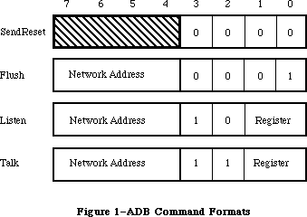 Figure 1–ADB Command Formats
The individual commands are discussed below.
Warning: Values of the low bytes of the ADB command formats other than
those shown in Figure 1 are reserved, and should not be used.
»SendReset
The SendReset command forces a hardware reset of all devices connected to the ADB. Such a reset clears all pending device actions and places the devices in their startup state. All devices are able to accept new ADB commands and user inputs immediately thereafter. All devices ignore the high-order four bits of the SendReset command.
»Flush
The Flush command flushes data from the single device specified by the network address in its high-order four bits. Network addresses are discussed below, under “Device Addressing”. It purges any pending user inputs and make the device ready to accept new commands and input data.
»Listen
The Listen command is used to send instructions to devices connected to the ADB. It transfers data from a buffer in system RAM to a register in the device specified by the network address in its high-order four bits. The device register is specified by the low-order two bits of the Listen command.
»Talk
The Talk command is used to fetch user inputs from devices connected to the ADB. It is the complement of the Listen command. It transfers data from a register in the device specified by the network address in its high-order four bits to a buffer in system RAM. The device register is specified by the low-order two bits of the Talk command.
_______________________________________________________________________________
»Device Registers
Each device connected to the ADB contains four registers, each of which may store from two to eight bytes of data. Each register is identified by the value of the low-order two bits in a Listen or Talk command. Registers 0 and 3 have dedicated functions; registers 1 and 2 are used for purposes specific to each device, and need not be present in a device.
Note: ADB device registers are virtual registers; they need not be
implemented physically. The device firmware must only respond
to register commands as if a register were present.
»Register 0
Device register 0 is reserved for input data. If the device has user-input data to be fetched, it places the data in register 0 and requests service. It continues to request service until the system retrieves its data. The system responds to data-input requests with the following polling sequence:
• It generates a Talk command for register 0 in each device connected
to the ADB.
• If the device has data to send, it responds. The system does not
poll the next device until the data is exhausted.
• If the device has no data to send, or if its data is exhausted, the
VIA generates an interrupt. The system then polls the next device.
• This process continues until no devices request service.
»Register 3
Device register 3 is reserved for device identification data and operating flags. Application programs may set this data with Listen commands and read it with Talk commands. Register 3 stores 16 bits, divided into the fields shown in Figure 2.
Figure 1–ADB Command Formats
The individual commands are discussed below.
Warning: Values of the low bytes of the ADB command formats other than
those shown in Figure 1 are reserved, and should not be used.
»SendReset
The SendReset command forces a hardware reset of all devices connected to the ADB. Such a reset clears all pending device actions and places the devices in their startup state. All devices are able to accept new ADB commands and user inputs immediately thereafter. All devices ignore the high-order four bits of the SendReset command.
»Flush
The Flush command flushes data from the single device specified by the network address in its high-order four bits. Network addresses are discussed below, under “Device Addressing”. It purges any pending user inputs and make the device ready to accept new commands and input data.
»Listen
The Listen command is used to send instructions to devices connected to the ADB. It transfers data from a buffer in system RAM to a register in the device specified by the network address in its high-order four bits. The device register is specified by the low-order two bits of the Listen command.
»Talk
The Talk command is used to fetch user inputs from devices connected to the ADB. It is the complement of the Listen command. It transfers data from a register in the device specified by the network address in its high-order four bits to a buffer in system RAM. The device register is specified by the low-order two bits of the Talk command.
_______________________________________________________________________________
»Device Registers
Each device connected to the ADB contains four registers, each of which may store from two to eight bytes of data. Each register is identified by the value of the low-order two bits in a Listen or Talk command. Registers 0 and 3 have dedicated functions; registers 1 and 2 are used for purposes specific to each device, and need not be present in a device.
Note: ADB device registers are virtual registers; they need not be
implemented physically. The device firmware must only respond
to register commands as if a register were present.
»Register 0
Device register 0 is reserved for input data. If the device has user-input data to be fetched, it places the data in register 0 and requests service. It continues to request service until the system retrieves its data. The system responds to data-input requests with the following polling sequence:
• It generates a Talk command for register 0 in each device connected
to the ADB.
• If the device has data to send, it responds. The system does not
poll the next device until the data is exhausted.
• If the device has no data to send, or if its data is exhausted, the
VIA generates an interrupt. The system then polls the next device.
• This process continues until no devices request service.
»Register 3
Device register 3 is reserved for device identification data and operating flags. Application programs may set this data with Listen commands and read it with Talk commands. Register 3 stores 16 bits, divided into the fields shown in Figure 2.
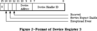 Figure 2–Format of Device Register 3
Except for commands that contain certain reserved device handler ID values
(listed below), every command to register 3 changes the entire register contents. Hence to change part of the register, you should first fetch its current contents with a Talk command and then send it an updated value with Listen. You can change part of the contents of register 3 by using special device handler ID values, as described below.
The device handler ID field indicates the device’s type. With certain devices, an application can change the device’s mode of operation by sending it a new ID value. If the device supports the new mode, it stores the new value in this field.
Warning: You are assigned handler IDs by Apple Software Licensing, so
they do not conflict with the values of other devices that may
be connected to the ADB at the same time.
When certain reserved values are sent to the device handler ID field by a Listen command, they are not stored in the field; instead, they cause specific device actions. Hence these values cannot be used as device ID values. They are the following:
Value Action
$00 Change bits 8–13 of register 3 to match the rest of the command;
leave Device Handler ID value unchanged.
$FD Change Device Address to match bits 8–11 if the device activator
has been depressed; leave Device Handler ID value and flags unchanged.
$FE Change Device Address to match bits 8–11 if the result produces no
address duplication on the bus; leave Device Handler ID value and
flags unchanged.
$FF Initiate device self-test. If self-test succeeds, leave register 3
unchanged; if self-test fails, clear Device Handler ID field to $00.
Other Device Handler ID values may be stored in the field.
Note: Device Handler ID values below $20 are reserved by Apple.
The Device Address field indicates the device’s location within the 16 possible device locations of the ADB. An application may change its value with a Listen command. When this field is interrogated with a Talk command, it returns a random value. This helps you separate multiple devices that have the same ADB address; for further information, see “Device Addressing”, below.
The Service Request Enable bit is set by the device to request an interrupt poll.
_______________________________________________________________________________
»Device Addressing
There are 16 possible direct addresses, $00–$0F, for devices connected to the ADB. However, it is possible to connect more than one device to an address; this might happen, for example, in a system with two alternate keyboards.
When several devices share a single ADB address, but there are free addresses available in the net, the system will automatically reassign addresses until they are all different. It will do this every time the ADB Manager is initialized or reinitialized. To find out a device’s new address, use the calls GetIndADB or GetADBInfo, described later in this chapter.
_______________________________________________________________________________
»Standard ADB Device Drivers
The Macintosh II and Macintosh SE systems contain two standard ADB drivers:
• the mouse driver, which supports the ADB mouse. The Apple mouse
has an original ADB address of 3.
• the universal keyboard driver, which supports all Apple ADB keyboards.
The Apple keyboard has an original ADB address of 2, with a Device
Handler ID of 1 for the Macintosh II keyboard and 2 for the Apple
Extended Keyboard. These keyboards are described in the Toolbox
Event Manager chapter.
These drivers reside in the system ROM. In addition, ADB address 0 is reserved for the ADB chip itself. You can change the ADB addresses of the mouse or keyboard, as described above under “Device Registers,” but Apple does not recommend doing so.
Assembly-language note: The ADB address of the keyboard on which the
last-typed character was entered is now stored
in the global variable KbdLast. The type of the
keyboard on which the last-typed character was
entered is stored in the global variable KbdType.
The value of KbdType is the Device Handler ID
value in Register 3 of the device; values below
$20 are reserved by Apple.
The requirements for writing new ADB device drivers are discussed later in this chapter.
_______________________________________________________________________________
»ADB MANAGER ROUTINES
_______________________________________________________________________________
The ADB Manager consists of six routines located in the 256K ROM. You would use them only if you needed to access bus devices directly or communicate with a special device.
Some of these routines access and update information in the ADB device table, a structure placed in the system heap by ROM code during system startup. It lists for each device the device’s type, its original ADB address, its current ADB address, the address of the routine that services the device, and the address of the area in RAM used for temporary data storage by its driver. The ADB device table is accessible only through ADB Manager routines.
PROCEDURE ADBReInit;
Trap macro _ADBReInit
ADBReInit reinitializes the entire Apple Desktop Bus. It clears the ADB device table to zeros and places a SendReset command on the bus to reset all devices to their original addresses. ADBReInit has no parameters.
Because it does not deallocate ADB resources on the system heap, ADBReInit should not be used for routine bus initialization. Apple strongly recommends against adding devices while the system is running; therefore, you should never call ADBReInit.
ADBReInit also calls a routine pointed to by the low memory global JADBProc
at the beginning and end of its execution. You can insert your own
preprocessing/postprocessing routine by changing the value of JADBProc; ADBReInit conditions it by setting D0 to 0 for preprocessing and to 1 for postprocessing. Your procedure must restore the value of D0 and branch to the original value of JADBProc on exit. JADBProc should be used to de-allocate memory used by the driver (see MacDTS Sample Code “TbltDrvr” for an example), and then it should chain to the procedure originally found in JADBProc.
The complete ADBReInit sequence is therefore the following:
• JSR to JADBProc with D0 set to 0
• reinitialize the Apple Desktop Bus
• clear the ADB device table
• JSR to JADBProc with D0 set to 1
FUNCTION ADBOp (data: Ptr; compRout: ProcPtr; buffer: Ptr;
commandNum: INTEGER) : OSErr;
Trap macro _ADBOp
On entry: A0: pointer to parameter block
D0: commandNum (byte)
Parameter block
--> 0 buffer pointer
--> 4 compRout pointer
--> 8 data pointer
On exit: D0: result code (byte)
The completion routine pointed to by compRout will be passed the following parameters on entry:
D0: commandNum (byte)
A0: pointer to buffer, data stored as a Pascal string (maximum
8 bytes data preceded by one length byte)
A1: pointer to completion routine (compRout)
A2: pointer to optional data area (data)
ADBOp transmits over the bus the command byte whose value is given by commandNum. The structure of the command byte is given earlier in Figure 1. ADBOp executes only when the ADB is otherwise idle; otherwise it is held in a command queue. It returns an error if the command queue is full. The length of the data buffer pointed to by buffer is contained in its first byte, like a Pascal string. The optional data area pointed to by data is for local storage by the completion routine pointed to by compRout. ADBop should be used sparingly; it is not intended for polling a device. The host automatically polls devices with data to deliver.
Result codes noErr No error
–1 Unsuccessful completion
FUNCTION CountADBs: INTEGER;
Trap macro _CountADBs
On exit: D0: number of devices (byte)
CountADBs returns a value representing the number of devices connected to the ADB by counting the number of entries in the device table. It has no arguments and returns no error codes.
FUNCTION GetIndADB (VAR info: ADBDataBlock;
devTableIndex: INTEGER) : ADBAddress;
Trap macro _GetIndADB
On entry: A0: pointer to parameter block
D0: entry index number; range = 1..CountADBs (byte)
Parameter block
<-- 0 device type byte (handler ID)
<-- 1 original ADB address byte
<-- 2 service routine address pointer (compRout)
<-- 6 data area address pointer (data)
On exit: D0: positive value: current ADB address (byte)
negative value: error code (byte)
GetIndADB returns information from the ADB device table entry whose index number is given by devTableIndex. ADBDataBlock has this form:
TYPE ADBDataBlock =
PACKED RECORD
devType: SignedByte; {device type (handler ID)}
origADBAddr: SignedByte; {original ADB address}
dbServiceRtPtr: Ptr; {service routine address (compRout)}
dbDataAreaAddr: Ptr {data area address (data)}
END;
GetIndADB returns the current ADB address of the device. If it is unable to complete execution successfully, GetIndADB returns a negative value.
FUNCTION GetADBInfo (VAR info: ADBDataBlock; ADBAddr: ADBAddress) : OsErr;
Trap macro _GetADBInfo
On entry: A0: pointer to parameter block
D0: ADB address of the device (byte)
Parameter block
<-- 0 device handler ID byte
<-- 1 original ADB address byte
<-- 2 service routine address pointer (compRout)
<-- 6 data area address pointer (data)
On exit: D0: result code (byte)
GetADBInfo returns information from the ADB device table entry of the device whose ADB address is given by ABDAddr. The structure of ADBDataBlock is given above under “GetIndADB”.
Result codes noErr No error
FUNCTION SetADBInfo (VAR info: ADBSetInfoBlock; ADBAddr: ADBAddress) : OsErr;
Trap macro _SetADBInfo
On entry: A0: pointer to parameter block
D0: ADB address of the device (byte)
Parameter block
--> 0 service routine address pointer (compRout)
--> 4 data area address pointer (data)
On exit: D0: result code (byte)
SetADBInfo sets the service routine address and the data area address in the ADB device table entry for the device whose ADB address is given by ABDAddr. ADBSetInfoBlock has this form:
TYPE ADBSetInfoBlock =
RECORD
siServiceRtPtr: Ptr; {service routine address (compRout)}
siDataAreaAddr: Ptr {data area address (data)}
END;
Result codes noErr No error
Warning: You should send a Flush command to the device after calling it
with SetADBInfo, to prevent it sending old data to the new data
area address.
_______________________________________________________________________________
»WRITING ADB DEVICE DRIVERS
_______________________________________________________________________________
Drivers for devices connected to the ADB have the following special requirements:
• Each ADB device driver must reside in a resource of type 'ADBS'.
(An example 'ADBS' resource is available in MacDTS Sample Code
“TbltDrvr.”) This type has two sections: initialization and driver code.
• The initialization section of each ADB device driver must support the
installation procedure described below.
When the system calls an ADB device driver, it passes it the following values:
• Register A0 points to the data buffer, which is formatted as a
Pascal string (buffer).
• Register A1 points to the driver’s completion routine (compRout).
• Register A2 points to the optional data area (data).
• Register D0 contains the ADB command that resulted in the driver
being called (commandNum).
The ADB driver should handle the ADB command passed to it and store any resulting input data by an appropriate action, such as by posting an event or moving the cursor.
Note: Events posted from keyboards connected to the ADB now have an
expanded structure. For more information, see the Toolbox Event
Manager chapter.
_______________________________________________________________________________
»Installing an ADB Driver
The Start Manager (described in this volume) finds all the ADB devices connected to the system and places their device types and ADB addresses in the ADB device table. It then calls the initialization section of each ADB device driver by executing the initialization code in its 'ADBS' resource.
As a minimum, the initialization section of each ADB device driver must do the following:
• The driver must allocate all the memory required by the driver code
in one or more nonrelocatable blocks in the system heap area.
• The driver must install its own preprocessing/postprocessing routine
(if any) as described above under “ADBReInit”.
• Finally, the driver must initialize the service routine address and
data area address of its entry in the ADB device table, using SetADBInfo.
_______________________________________________________________________________
»SUMMARY OF THE ADB MANAGER
_______________________________________________________________________________
Data Types
TYPE
ADBDataBlock =
PACKED RECORD
devType: SignedByte; {Handler ID}
origADBAddr: SignedByte; {original ADB address}
dbServiceRtPtr: Ptr; {service routine address (compRout)}
dbDataAreaAddr: Ptr {data area address (area)}
END;
ADBSetInfoBlock =
RECORD
siServiceRtPtr: Ptr; {service routine address}
siDataAreaAddr: Ptr {data area address}
END;
_______________________________________________________________________________
Routines
Initializing the ADB Manager
PROCEDURE ADBReInit;
Communicating Through the ADB
FUNCTION ADBOp (data: Ptr; compRout: ProcPtr; buffer: Ptr;
commandNum: INTEGER) : OSErr;
Getting ADB Device Information
FUNCTION CountADBs: INTEGER;
FUNCTION GetIndADB (VAR info: ADBDataBlock;
devTableIndex: INTEGER) : ADBAddress;
FUNCTION GetADBInfo (VAR info: ADBDataBlock; ADBAddr: ADBAddress) : OsErr;
Setting ADB Device Information
FUNCTION SetADBInfo (VAR info: ADBSetInfoBlock; ADBAddr: ADBAddress) : OsErr;
_______________________________________________________________________________
Assembly-Language Information
Variables
JADBProc Pointer to ADBReInit preprocessing/postprocessing routine
KbdLast ADB address of the keyboard last used (byte)
KbdType Keyboard type of the keyboard last used (byte)
Routines
Trap macro On entry On Exit
_ADBReInit
_ADBOp A0: pointer to parameter block D0: result code (byte)
buffer (pointer)
compRout (pointer)
data (pointer)
D0: commandNum (byte)
_CountADBs D0: result code (byte)
_GetIndADB A0: pointer to parameter block D0: positive value:
device type (byte) current ADB
original ADB address (byte) address (byte)
service routine address (pointer) negative value:
data area address (pointer) error code (byte)
D0: entry index number;
range = 1..CountADBs (byte)
_GetADBInfo A0: pointer to parameter block D0: result code (byte)
device handler ID (byte)
original ADB address (byte)
service routine address (pointer)
data area address (pointer)
D0: current ADB address of the device (byte)
_SetADBInfo A0: pointer to parameter block D0: result code (byte)
service routine address (pointer)
data area address (pointer)
D0: current ADB address of the device (byte)
Further Reference:
_______________________________________________________________________________
Toolbox Event Manager
Technical Note #143, Don’t Call ADBReInit on the SE with System 4.1
Technical Note #160, Key Mapping
Technical Note #206, Space Aliens Ate My Mouse
“Macintosh Family Hardware Reference”
Figure 2–Format of Device Register 3
Except for commands that contain certain reserved device handler ID values
(listed below), every command to register 3 changes the entire register contents. Hence to change part of the register, you should first fetch its current contents with a Talk command and then send it an updated value with Listen. You can change part of the contents of register 3 by using special device handler ID values, as described below.
The device handler ID field indicates the device’s type. With certain devices, an application can change the device’s mode of operation by sending it a new ID value. If the device supports the new mode, it stores the new value in this field.
Warning: You are assigned handler IDs by Apple Software Licensing, so
they do not conflict with the values of other devices that may
be connected to the ADB at the same time.
When certain reserved values are sent to the device handler ID field by a Listen command, they are not stored in the field; instead, they cause specific device actions. Hence these values cannot be used as device ID values. They are the following:
Value Action
$00 Change bits 8–13 of register 3 to match the rest of the command;
leave Device Handler ID value unchanged.
$FD Change Device Address to match bits 8–11 if the device activator
has been depressed; leave Device Handler ID value and flags unchanged.
$FE Change Device Address to match bits 8–11 if the result produces no
address duplication on the bus; leave Device Handler ID value and
flags unchanged.
$FF Initiate device self-test. If self-test succeeds, leave register 3
unchanged; if self-test fails, clear Device Handler ID field to $00.
Other Device Handler ID values may be stored in the field.
Note: Device Handler ID values below $20 are reserved by Apple.
The Device Address field indicates the device’s location within the 16 possible device locations of the ADB. An application may change its value with a Listen command. When this field is interrogated with a Talk command, it returns a random value. This helps you separate multiple devices that have the same ADB address; for further information, see “Device Addressing”, below.
The Service Request Enable bit is set by the device to request an interrupt poll.
_______________________________________________________________________________
»Device Addressing
There are 16 possible direct addresses, $00–$0F, for devices connected to the ADB. However, it is possible to connect more than one device to an address; this might happen, for example, in a system with two alternate keyboards.
When several devices share a single ADB address, but there are free addresses available in the net, the system will automatically reassign addresses until they are all different. It will do this every time the ADB Manager is initialized or reinitialized. To find out a device’s new address, use the calls GetIndADB or GetADBInfo, described later in this chapter.
_______________________________________________________________________________
»Standard ADB Device Drivers
The Macintosh II and Macintosh SE systems contain two standard ADB drivers:
• the mouse driver, which supports the ADB mouse. The Apple mouse
has an original ADB address of 3.
• the universal keyboard driver, which supports all Apple ADB keyboards.
The Apple keyboard has an original ADB address of 2, with a Device
Handler ID of 1 for the Macintosh II keyboard and 2 for the Apple
Extended Keyboard. These keyboards are described in the Toolbox
Event Manager chapter.
These drivers reside in the system ROM. In addition, ADB address 0 is reserved for the ADB chip itself. You can change the ADB addresses of the mouse or keyboard, as described above under “Device Registers,” but Apple does not recommend doing so.
Assembly-language note: The ADB address of the keyboard on which the
last-typed character was entered is now stored
in the global variable KbdLast. The type of the
keyboard on which the last-typed character was
entered is stored in the global variable KbdType.
The value of KbdType is the Device Handler ID
value in Register 3 of the device; values below
$20 are reserved by Apple.
The requirements for writing new ADB device drivers are discussed later in this chapter.
_______________________________________________________________________________
»ADB MANAGER ROUTINES
_______________________________________________________________________________
The ADB Manager consists of six routines located in the 256K ROM. You would use them only if you needed to access bus devices directly or communicate with a special device.
Some of these routines access and update information in the ADB device table, a structure placed in the system heap by ROM code during system startup. It lists for each device the device’s type, its original ADB address, its current ADB address, the address of the routine that services the device, and the address of the area in RAM used for temporary data storage by its driver. The ADB device table is accessible only through ADB Manager routines.
PROCEDURE ADBReInit;
Trap macro _ADBReInit
ADBReInit reinitializes the entire Apple Desktop Bus. It clears the ADB device table to zeros and places a SendReset command on the bus to reset all devices to their original addresses. ADBReInit has no parameters.
Because it does not deallocate ADB resources on the system heap, ADBReInit should not be used for routine bus initialization. Apple strongly recommends against adding devices while the system is running; therefore, you should never call ADBReInit.
ADBReInit also calls a routine pointed to by the low memory global JADBProc
at the beginning and end of its execution. You can insert your own
preprocessing/postprocessing routine by changing the value of JADBProc; ADBReInit conditions it by setting D0 to 0 for preprocessing and to 1 for postprocessing. Your procedure must restore the value of D0 and branch to the original value of JADBProc on exit. JADBProc should be used to de-allocate memory used by the driver (see MacDTS Sample Code “TbltDrvr” for an example), and then it should chain to the procedure originally found in JADBProc.
The complete ADBReInit sequence is therefore the following:
• JSR to JADBProc with D0 set to 0
• reinitialize the Apple Desktop Bus
• clear the ADB device table
• JSR to JADBProc with D0 set to 1
FUNCTION ADBOp (data: Ptr; compRout: ProcPtr; buffer: Ptr;
commandNum: INTEGER) : OSErr;
Trap macro _ADBOp
On entry: A0: pointer to parameter block
D0: commandNum (byte)
Parameter block
--> 0 buffer pointer
--> 4 compRout pointer
--> 8 data pointer
On exit: D0: result code (byte)
The completion routine pointed to by compRout will be passed the following parameters on entry:
D0: commandNum (byte)
A0: pointer to buffer, data stored as a Pascal string (maximum
8 bytes data preceded by one length byte)
A1: pointer to completion routine (compRout)
A2: pointer to optional data area (data)
ADBOp transmits over the bus the command byte whose value is given by commandNum. The structure of the command byte is given earlier in Figure 1. ADBOp executes only when the ADB is otherwise idle; otherwise it is held in a command queue. It returns an error if the command queue is full. The length of the data buffer pointed to by buffer is contained in its first byte, like a Pascal string. The optional data area pointed to by data is for local storage by the completion routine pointed to by compRout. ADBop should be used sparingly; it is not intended for polling a device. The host automatically polls devices with data to deliver.
Result codes noErr No error
–1 Unsuccessful completion
FUNCTION CountADBs: INTEGER;
Trap macro _CountADBs
On exit: D0: number of devices (byte)
CountADBs returns a value representing the number of devices connected to the ADB by counting the number of entries in the device table. It has no arguments and returns no error codes.
FUNCTION GetIndADB (VAR info: ADBDataBlock;
devTableIndex: INTEGER) : ADBAddress;
Trap macro _GetIndADB
On entry: A0: pointer to parameter block
D0: entry index number; range = 1..CountADBs (byte)
Parameter block
<-- 0 device type byte (handler ID)
<-- 1 original ADB address byte
<-- 2 service routine address pointer (compRout)
<-- 6 data area address pointer (data)
On exit: D0: positive value: current ADB address (byte)
negative value: error code (byte)
GetIndADB returns information from the ADB device table entry whose index number is given by devTableIndex. ADBDataBlock has this form:
TYPE ADBDataBlock =
PACKED RECORD
devType: SignedByte; {device type (handler ID)}
origADBAddr: SignedByte; {original ADB address}
dbServiceRtPtr: Ptr; {service routine address (compRout)}
dbDataAreaAddr: Ptr {data area address (data)}
END;
GetIndADB returns the current ADB address of the device. If it is unable to complete execution successfully, GetIndADB returns a negative value.
FUNCTION GetADBInfo (VAR info: ADBDataBlock; ADBAddr: ADBAddress) : OsErr;
Trap macro _GetADBInfo
On entry: A0: pointer to parameter block
D0: ADB address of the device (byte)
Parameter block
<-- 0 device handler ID byte
<-- 1 original ADB address byte
<-- 2 service routine address pointer (compRout)
<-- 6 data area address pointer (data)
On exit: D0: result code (byte)
GetADBInfo returns information from the ADB device table entry of the device whose ADB address is given by ABDAddr. The structure of ADBDataBlock is given above under “GetIndADB”.
Result codes noErr No error
FUNCTION SetADBInfo (VAR info: ADBSetInfoBlock; ADBAddr: ADBAddress) : OsErr;
Trap macro _SetADBInfo
On entry: A0: pointer to parameter block
D0: ADB address of the device (byte)
Parameter block
--> 0 service routine address pointer (compRout)
--> 4 data area address pointer (data)
On exit: D0: result code (byte)
SetADBInfo sets the service routine address and the data area address in the ADB device table entry for the device whose ADB address is given by ABDAddr. ADBSetInfoBlock has this form:
TYPE ADBSetInfoBlock =
RECORD
siServiceRtPtr: Ptr; {service routine address (compRout)}
siDataAreaAddr: Ptr {data area address (data)}
END;
Result codes noErr No error
Warning: You should send a Flush command to the device after calling it
with SetADBInfo, to prevent it sending old data to the new data
area address.
_______________________________________________________________________________
»WRITING ADB DEVICE DRIVERS
_______________________________________________________________________________
Drivers for devices connected to the ADB have the following special requirements:
• Each ADB device driver must reside in a resource of type 'ADBS'.
(An example 'ADBS' resource is available in MacDTS Sample Code
“TbltDrvr.”) This type has two sections: initialization and driver code.
• The initialization section of each ADB device driver must support the
installation procedure described below.
When the system calls an ADB device driver, it passes it the following values:
• Register A0 points to the data buffer, which is formatted as a
Pascal string (buffer).
• Register A1 points to the driver’s completion routine (compRout).
• Register A2 points to the optional data area (data).
• Register D0 contains the ADB command that resulted in the driver
being called (commandNum).
The ADB driver should handle the ADB command passed to it and store any resulting input data by an appropriate action, such as by posting an event or moving the cursor.
Note: Events posted from keyboards connected to the ADB now have an
expanded structure. For more information, see the Toolbox Event
Manager chapter.
_______________________________________________________________________________
»Installing an ADB Driver
The Start Manager (described in this volume) finds all the ADB devices connected to the system and places their device types and ADB addresses in the ADB device table. It then calls the initialization section of each ADB device driver by executing the initialization code in its 'ADBS' resource.
As a minimum, the initialization section of each ADB device driver must do the following:
• The driver must allocate all the memory required by the driver code
in one or more nonrelocatable blocks in the system heap area.
• The driver must install its own preprocessing/postprocessing routine
(if any) as described above under “ADBReInit”.
• Finally, the driver must initialize the service routine address and
data area address of its entry in the ADB device table, using SetADBInfo.
_______________________________________________________________________________
»SUMMARY OF THE ADB MANAGER
_______________________________________________________________________________
Data Types
TYPE
ADBDataBlock =
PACKED RECORD
devType: SignedByte; {Handler ID}
origADBAddr: SignedByte; {original ADB address}
dbServiceRtPtr: Ptr; {service routine address (compRout)}
dbDataAreaAddr: Ptr {data area address (area)}
END;
ADBSetInfoBlock =
RECORD
siServiceRtPtr: Ptr; {service routine address}
siDataAreaAddr: Ptr {data area address}
END;
_______________________________________________________________________________
Routines
Initializing the ADB Manager
PROCEDURE ADBReInit;
Communicating Through the ADB
FUNCTION ADBOp (data: Ptr; compRout: ProcPtr; buffer: Ptr;
commandNum: INTEGER) : OSErr;
Getting ADB Device Information
FUNCTION CountADBs: INTEGER;
FUNCTION GetIndADB (VAR info: ADBDataBlock;
devTableIndex: INTEGER) : ADBAddress;
FUNCTION GetADBInfo (VAR info: ADBDataBlock; ADBAddr: ADBAddress) : OsErr;
Setting ADB Device Information
FUNCTION SetADBInfo (VAR info: ADBSetInfoBlock; ADBAddr: ADBAddress) : OsErr;
_______________________________________________________________________________
Assembly-Language Information
Variables
JADBProc Pointer to ADBReInit preprocessing/postprocessing routine
KbdLast ADB address of the keyboard last used (byte)
KbdType Keyboard type of the keyboard last used (byte)
Routines
Trap macro On entry On Exit
_ADBReInit
_ADBOp A0: pointer to parameter block D0: result code (byte)
buffer (pointer)
compRout (pointer)
data (pointer)
D0: commandNum (byte)
_CountADBs D0: result code (byte)
_GetIndADB A0: pointer to parameter block D0: positive value:
device type (byte) current ADB
original ADB address (byte) address (byte)
service routine address (pointer) negative value:
data area address (pointer) error code (byte)
D0: entry index number;
range = 1..CountADBs (byte)
_GetADBInfo A0: pointer to parameter block D0: result code (byte)
device handler ID (byte)
original ADB address (byte)
service routine address (pointer)
data area address (pointer)
D0: current ADB address of the device (byte)
_SetADBInfo A0: pointer to parameter block D0: result code (byte)
service routine address (pointer)
data area address (pointer)
D0: current ADB address of the device (byte)
Further Reference:
_______________________________________________________________________________
Toolbox Event Manager
Technical Note #143, Don’t Call ADBReInit on the SE with System 4.1
Technical Note #160, Key Mapping
Technical Note #206, Space Aliens Ate My Mouse
“Macintosh Family Hardware Reference”
The AppleTalk Manager
_______________________________________________________________________________
THE APPLETALK MANAGER
_______________________________________________________________________________
About This Chapter
AppleTalk Protocols
AppleTalk Transaction Protocol
Transactions
Datagram Loss Recovery
About the AppleTalk Manager
Calling the AppleTalk Manager from Pascal
Opening and Closing AppleTalk
AppleTalk Link Access Protocol
Data Structures
Using ALAP
ALAP Routines
Example
Datagram Delivery Protocol
Data Structures
Using DDP
DDP Routines
Example
AppleTalk Transaction Protocol
Data Structures
Using ATP
ATP Routines
Example
Name-Binding Protocol
Data Structures
Using NBP
NBP Routines
Example
Miscellaneous Routines
New AppleTalk Manager Pascal Interface
Using Pascal
MPP Parameter Block
ATP Parameter Block
Building Data Structures
Picking a Node Address in the Server Range
Sending Packets to One’s Own Node
ATP Driver Changes
Sending an ATP Request Through a Specified Socket
Aborting ATP SendRequests
Aborting ATP GetRequests
Name Binding Protocol Changes
Multiple Concurrent NBP Requests
KillNBP function
Variable Resources
Calling the AppleTalk Manager from Assembly Language
Opening AppleTalk
Example
AppleTalk Link Access Protocol
Data Structures
Using ALAP
ALAP Routines
Datagram Delivery Protocol
Data Structures
Using DDP
DDP Routines
AppleTalk Transaction Protocol
Data Structures
Using ATP
ATP Routines
Name-Binding Protocol
Data Structures
Using NBP
NBP Routines
Extended Protocol Package Driver
Version
Error Reporting
.XPP Driver Functions Overview
Using AppleTalk Name Binding Protocol
Opening and Closing Sessions
Session Maintenance
Commands on an Open Session
Getting Server Status Information
Attention Mechanism
The Attention Routine
Calling the .XPP Driver
Using XPP
Allocating Memory
Opening the .XPP Driver
Example
Open Errors
Closing the .XPP Driver
Close Errors
Session Control Block
How to Access the .XPP Driver
General
.XPP Driver Parameter Block Record
AppleTalk Session Protocol Functions
Note on Result Codes
AFP Implementation
Mapping AFP Commands
AFPCall Function
General Command Format
Login Command Format
AFPWrite Command Format
AFPRead Command Format
CCB Sizes
.XPP Driver Result Codes
Protocol Handlers and Socket Listeners
Data Reception in the AppleTalk Manager
Writing Protocol Handlers
Timing Considerations
Writing Socket Listeners
Summary of the AppleTalk Manager
_______________________________________________________________________________
»ABOUT THIS CHAPTER
_______________________________________________________________________________
The AppleTalk Manager is an interface to a pair of RAM device drivers that allow Macintosh programs to send and receive information via an AppleTalk network. This chapter describes the AppleTalk Manager in detail.
The AppleTalk Manager has been enhanced through the implementation of new protocols and an increase in the functionality of the existing interface.
Reader’s guide: The AppleTalk Manager provides services that allow Macintosh
programs to interact with clients in devices connected to an
AppleTalk network. Hence you need the information in this
chapter only if your application uses AppleTalk.
The following is a brief summary of the changes that have been made to the AppleTalk Manager interface.
• New parameter block–style Pascal calls have been added for the entire
AppleTalk Manager. These new calls give the application programmer
better control of AppleTalk operation within an application.
• At open time, the .MPP driver can be told to pick a node number in
the server range. This is a more time consuming but more thorough
operation than is selecting a node number in the workstation range,
and it is required for devices acting as servers.
• Multiple concurrent NBP requests are now supported (just as multiple
concurrent ATP requests have been supported). The KillNBP command
has been implemented to abort an outstanding NBP request.
• ATP requests can now be sent through client-specified sockets, instead
of having ATP pick the socket itself.
• The ability to send packets to one’s own node is supported (although
this functionality is, in the default case, disabled).
• Two new ATP abort calls have been added: KillSendReq and KillGetReq.
KillSendReq is functionally equivalent to RelTCB, although its
arguments are different. KillGetReq is a new call for aborting
outstanding GetRequests.
• Additional machine-dependent resources have been added to support,
for example, more dynamic sockets and more concurrent ATP requests.
• A new protocol called the Echo Protocol (EP) is supported.
• A new driver, .XPP, has been added. The .XPP driver implements the
workstation side of the AppleTalk Session Protocol (ASP) and a small
portion of the AppleTalk Filing Protocol.
To determine if your application is running on a machine that supports these enhanced features, check the version number of the .MPP driver (at offset DCtlQueue+1 in the Device Control Entry). A version number of 48 (NCVersion) or greater indicates the presence of the new drivers.
You should already be familiar with:
• events, as discussed in the Toolbox Event Manager chapter
• interrupts and the use of devices and device drivers, as described in
the Device Manager chapter, if you want to write your own assembly-
language additions to the AppleTalk Manager
• the Inside AppleTalk manual, if you want to understand AppleTalk
protocols in detail
_______________________________________________________________________________
»APPLETALK PROTOCOLS
_______________________________________________________________________________
The AppleTalk Manager provides a variety of services that allow Macintosh programs to interact with programs in devices connected to an AppleTalk network. This interaction, achieved through the exchange of variable-length blocks of data (known as packets) over AppleTalk, follows well-defined sets of rules known as protocols.
Although most programmers using AppleTalk needn’t understand the details of these protocols, they should understand the information in this section—what the services provided by the different protocols are, and how the protocols are interrelated. Detailed information about AppleTalk protocols is available in Inside AppleTalk.
The AppleTalk system architecture consists of a number of protocols arranged in layers. Each protocol in a specific layer provides services to higher-level layers (known as the protocol’s clients) by building on the services provided by lower-level layers. A Macintosh program can use services provided by any of the layers in order to construct more sophisticated or more specialized services. Figure 1 shows the AppleTalk Protocols and their corresponding network layers.
The AppleTalk Manager contains the following protocols:
• AppleTalk Link Access Protocol
• Datagram Delivery Protocol
• Routing Table Maintenance Protocol
• Name-Binding Protocol
• AppleTalk Transaction Protocol
The following protocols have been added to the AppleTalk Manager:
• Echo Protocol
• AppleTalk Session Protocol (workstation side)
• AppleTalk Filing Protocol (small portion of the workstation side)
In Figure 1, the lines indicate the interaction between the protocols. Notice that like the Routing Table Maintenance Protocol, the Echo Protocol is not directly accessible to Macintosh programs.
The details of these protocols are provided in Inside AppleTalk.
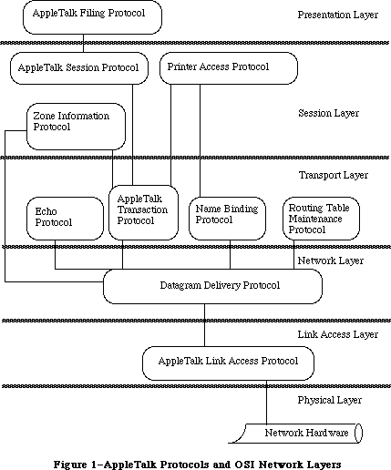 Figure 1–AppleTalk Protocols and OSI Network Layers
Figure 2 illustrates the Macintosh AppleTalk Drivers and the layered structure of the protocols which are accessible through each driver. Note that the Routing Table Maintenance Protocol isn’t directly accessible to Macintosh Programs.
Figure 1–AppleTalk Protocols and OSI Network Layers
Figure 2 illustrates the Macintosh AppleTalk Drivers and the layered structure of the protocols which are accessible through each driver. Note that the Routing Table Maintenance Protocol isn’t directly accessible to Macintosh Programs.
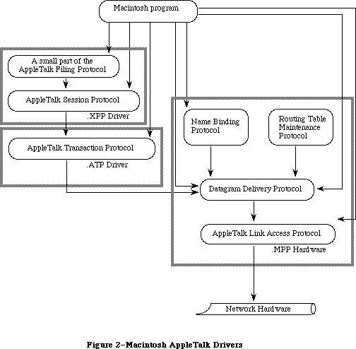 Figure 2–Macintosh AppleTalk Drivers
The AppleTalk Link Access Protocol (ALAP) provides the lowest-level services of the AppleTalk system. Its main function is to control access to the AppleTalk network among various competing devices. Each device connected to an AppleTalk network, known as a node, is assigned an eight-bit node ID number that identifies the node. ALAP ensures that each node on an AppleTalk network has a unique node ID, assigned dynamically when the node is started up.
ALAP provides its clients with node-to-node delivery of data frames on a single AppleTalk network. An ALAP frame is a variable-length packet of data preceded and followed by control information referred to as the ALAP frame header and frame trailer, respectively. The ALAP frame header includes the node IDs of the frame’s destination and source nodes. The AppleTalk hardware uses the destination node ID to deliver the frame. The frame’s source node ID allows a program in the receiving node to determine the identity of the source. A sending node can ask ALAP to send a frame to all nodes on the AppleTalk network; this broadcast service is obtained by specifying a destination node ID of 255.
ALAP can have multiple clients in a single node. When a frame arrives at a node, ALAP determines which client it should be delivered to by reading the frame’s ALAP protocol type. The ALAP protocol type is an eight-bit quantity, contained in the frame’s header, that identifies the ALAP client to whom the frame will be sent. ALAP calls the client’s protocol handler, which is a software process in the node that reads in and then services the frames. The protocol handlers for a node are listed in a protocol handler table.
An ALAP frame trailer contains a 16-bit frame check sequence generated by the AppleTalk hardware. The receiving node uses the frame check sequence to detect transmission errors, and discards frames with errors. In effect, a frame with an error is “lost” in the AppleTalk network, because ALAP doesn’t attempt to recover from errors by requesting the sending node to retransmit such frames. Thus ALAP is said to make a “best effort” to deliver frames, without any guarantee of delivery.
An ALAP frame can contain up to 600 bytes of client data. The first two bytes must be an integer equal to the length of the client data (including the length bytes themselves).
Datagram Delivery Protocol (DDP) provides the next-higher level protocol in the AppleTalk architecture, managing socket-to-socket delivery of datagrams over AppleTalk internets. DDP is an ALAP client, and uses the node-to-node delivery service provided by ALAP to send and receive datagrams. Datagrams are packets of data transmitted by DDP. A DDP datagram can contain up to 586 bytes of client data. Sockets are logical entities within the nodes of a network; each socket within a given node has a unique eight-bit socket number.
On a single AppleTalk network, a socket is uniquely identified by its AppleTalk address—its socket number together with its node ID. To identify a socket in the scope of an AppleTalk internet, the socket’s AppleTalk address and network number are needed. Internets are formed by interconnecting AppleTalk networks via intelligent nodes called bridges. A network number is a 16-bit number that uniquely identifies a network in an internet. A socket’s AppleTalk address together with its network number provide an internet-wide unique socket identifier called an internet address.
Sockets are owned by socket clients, which typically are software processes in the node. Socket clients include code called the socket listener, which receives and services datagrams addressed to that socket. Socket clients must open a socket before datagrams can be sent or received through it. Each node contains a socket table that lists the listener for each open socket.
A datagram is sent from its source socket through a series of AppleTalk networks, being passed on from bridge to bridge, until it reaches its destination network. The ALAP in the destination network then delivers the datagram to the node containing the destination socket. Within that node the datagram is received by ALAP calling the DDP protocol handler, and by the DDP protocol handler in turn calling the destination socket listener, which for most applications will be a higher-level protocol such as the AppleTalk Transaction Protocol.
Bridges on AppleTalk internets use the Routing Table Maintenance Protocol (RTMP) to maintain routing tables for routing datagrams through the internet. In addition, nonbridge nodes use RTMP to determine the number of the network to which they’re connected and the node ID of one bridge on their network. The RTMP code in nonbridge nodes contains only a subset of RTMP (the RTMP stub), and is a DDP client owning socket number 1 (the RTMP socket).
Socket clients are also known as network-visible entities, because they’re the primary accessible entities on an internet. Network-visible entities can choose to identify themselves by an entity name, an identifier of the form
object:type@zone
Each of the three fields of this name is an alphanumeric string of up to 32 characters. The object and type fields are arbitrary identifiers assigned by a socket client, to provide itself with a name and type descriptor (for example, abs:Mailbox). The zone field identifies the zone in which the socket client is located; a zone is an arbitrary subset of AppleTalk networks in an internet. A socket client can identify itself by as many different names as it chooses. These aliases are all treated as independent identifiers for the same socket client.
The Name-Binding Protocol (NBP) maintains a names table in each node that contains the name and internet address of each entity in that node. These name-address pairs are called NBP tuples. The collection of names tables in an internet is known as the names directory.
NBP allows its clients to add or delete their name-address tuples from the
node’s names table. It also allows its clients to obtain the internet addresses of entities from their names. This latter operation, known as name lookup (in the names directory), requires that NBP install itself as a DDP client and broadcast special name-lookup packets to the nodes in a specified zone. These datagrams are sent by NBP to the names information socket—socket number 2 in every node using NBP.
NBP clients can use special meta-characters in place of one or more of the three fields of the name of an entity it wishes to look up. The character “=” in the object or type field signifies “all possible values”. The zone field can be replaced by “*”, which signifies “this zone”—the zone in which the NBP client’s node is located. For example, an NBP client performing a lookup with the name
=:Mailbox@*
will obtain in return the entity names and internet addresses of all mailboxes in the client’s zone (excluding the client’s own names and addresses). The client can specify whether one or all of the matching names should be returned.
NBP clients specify how thorough a name lookup should be by providing NBP with the number of times (retry count) that NBP should broadcast the lookup packets and the time interval (retry interval) between these retries.
As noted above, ALAP and DDP provide “best effort” delivery services with no recovery mechanism when packets are lost or discarded because of errors. Although for many situations such a service suffices, the AppleTalk Transaction Protocol (ATP) provides a reliable loss-free transport service. ATP uses transactions, consisting of a transaction request and a transaction response, to deliver data reliably. Each transaction is assigned a 16-bit transaction ID number to distinguish it from other transactions. A transaction request is retransmitted by ATP until a complete response has been received, thus allowing for recovery from packet-loss situations. The retry interval and retry count are specified by the ATP client sending the request.
Although transaction requests must be contained in a single datagram, transaction responses can consist of as many as eight datagrams. Each datagram in a response is assigned a sequence number from 0 to 7, to indicate its ordering within the response.
ATP is a DDP client, and uses the services provided by DDP to transmit requests and responses. ATP supports both at-least-once and exactly-once transactions. Four of the bytes in an ATP header, called the user bytes, are provided for use by ATP’s clients—they’re ignored by ATP.
ATP’s transaction model and means of recovering from datagram loss are covered in detail below.
The Echo Protocol (EP) provides an echoing service through static socket number 4 known as the echoer socket. The echoer listens for packets received through this socket. Any correctly formed packet sent to the echoer socket on a node will be echoed back to its sender.
This simple protocol can be used for two important purposes:
• EP can be used by any Datagram Delivery Protocol (DDP) client to
determine if a particular node (known to have an echoer) is accessible
over an internet.
• EP is useful in determining the average time it takes for a packet to
travel to a remote node and back. This is very helpful in developing
client-dependent heuristics for estimating the timeouts to be specified
by clients of ATP, ASP, and other protocols.
Programs cannot access EP directly via the AppleTalk Manager. The EP implementation exists solely to respond to EP requests sent by other nodes. EP is a DDP client residing on statically-assigned socket 4, the echoing socket. Clients wishing to send EP requests (and receive EP responses) should use the Datagram Delivery Protocol (DDP) to send the appropriate packet. For more information about the EP packet format, see Inside AppleTalk.
The AppleTalk Session Protocol (ASP) provides for the setting up, maintaining and closing down of a session. A session is a logical relationship between two network entities, a workstation and a server. The workstation tells the server what to do, and the server responds with the appropriate actions. ASP makes sure that the session dialog is maintained in the correct sequence and that both ends of the conversation are properly participating.
ASP will generally be used between two communicating network entities where one is providing a service to the other (for example, a server is providing a service to a workstation) and the service provided is state-dependent. That is, the response to a particular request from an entity is dependent upon other previous requests from that entity. For example, a request to read bytes from a file is dependent upon a previous request to open that file in the first place. However, a request to return the time of day is independent of all such previous requests.
When the service provided is state-dependent, requests must be delivered to the server in the same order as generated by the workstation. ASP guarantees requests are delivered to the server in the order in which they are issued, and that duplicate requests are never delivered (another requirement of state-dependent service).
ASP is an asymmetric protocol, providing one set of services to the workstation and a different set of services to the server.
ASP workstation clients initiate (open) sessions, send requests (commands) on that session, and close sessions down. ASP server clients receive and respond
(through command replies) to these requests. ASP guarantees that these requests are delivered in the same order as they are made, and without duplication. ASP is also responsible for closing down the session if one end fails or becomes unreachable, and will inform its client (either server or workstation) of the action.
ASP also provides various additional services, such as allowing a workstation to obtain server status information without opening a session to a server, writing blocks of data from the workstation to the server end of the session, and providing the ability for a server to send an attention message to the workstation.
ASP assumes that the workstation client has a mechanism for looking up the network address of the server with which it wants to set up a session.
(Generally this is done using the AppleTalk Name Binding Protocol.)
Both ends of the session periodically check to see that the other end of the session is still responsive. If one end fails or becomes unreachable the other end closes the session.
ASP is a client of ATP and calls ATP for transport services.
ASP does not
• ensure that consecutive commands complete in the order in which they
were sent (and delivered) to the server
• understand or interpret the syntax or the semantics of the commands
sent to the server by the workstation
• allow the server to send commands to the workstation (The server
is allowed to alert the workstation through the server’s attention
mechanism only.)
Note: The .XPP driver does implement the workstation side of the
AppleTalk Filing Protocol login command.
The AppleTalk Filing Protocol (AFP) allows a workstation on an AppleTalk network to access files on an AFP file server. AFP specifies a remote filing system that provides user authentication and an access control mechanism that supports volume and folder-level access rights. For details of AFP, refer to Inside AppleTalk.
_______________________________________________________________________________
»APPLETALK TRANSACTION PROTOCOL
_______________________________________________________________________________
This section covers ATP in greater depth, providing more detail about three of its fundamental concepts: transactions, buffer allocation, and recovery of lost datagrams.
_______________________________________________________________________________
»Transactions
A transaction is a interaction between two ATP clients, known as the requester and the responder. The requester calls the .ATP driver in its node to send a transaction request (TReq) to the responder, and then awaits a response. The TReq is received by the .ATP driver in the responder’s node and is delivered to the responder. The responder then calls its .ATP driver to send back a transaction response (TResp), which is received by the requester’s .ATP driver and delivered to the requester. Figure 3 illustrates this process.
Figure 2–Macintosh AppleTalk Drivers
The AppleTalk Link Access Protocol (ALAP) provides the lowest-level services of the AppleTalk system. Its main function is to control access to the AppleTalk network among various competing devices. Each device connected to an AppleTalk network, known as a node, is assigned an eight-bit node ID number that identifies the node. ALAP ensures that each node on an AppleTalk network has a unique node ID, assigned dynamically when the node is started up.
ALAP provides its clients with node-to-node delivery of data frames on a single AppleTalk network. An ALAP frame is a variable-length packet of data preceded and followed by control information referred to as the ALAP frame header and frame trailer, respectively. The ALAP frame header includes the node IDs of the frame’s destination and source nodes. The AppleTalk hardware uses the destination node ID to deliver the frame. The frame’s source node ID allows a program in the receiving node to determine the identity of the source. A sending node can ask ALAP to send a frame to all nodes on the AppleTalk network; this broadcast service is obtained by specifying a destination node ID of 255.
ALAP can have multiple clients in a single node. When a frame arrives at a node, ALAP determines which client it should be delivered to by reading the frame’s ALAP protocol type. The ALAP protocol type is an eight-bit quantity, contained in the frame’s header, that identifies the ALAP client to whom the frame will be sent. ALAP calls the client’s protocol handler, which is a software process in the node that reads in and then services the frames. The protocol handlers for a node are listed in a protocol handler table.
An ALAP frame trailer contains a 16-bit frame check sequence generated by the AppleTalk hardware. The receiving node uses the frame check sequence to detect transmission errors, and discards frames with errors. In effect, a frame with an error is “lost” in the AppleTalk network, because ALAP doesn’t attempt to recover from errors by requesting the sending node to retransmit such frames. Thus ALAP is said to make a “best effort” to deliver frames, without any guarantee of delivery.
An ALAP frame can contain up to 600 bytes of client data. The first two bytes must be an integer equal to the length of the client data (including the length bytes themselves).
Datagram Delivery Protocol (DDP) provides the next-higher level protocol in the AppleTalk architecture, managing socket-to-socket delivery of datagrams over AppleTalk internets. DDP is an ALAP client, and uses the node-to-node delivery service provided by ALAP to send and receive datagrams. Datagrams are packets of data transmitted by DDP. A DDP datagram can contain up to 586 bytes of client data. Sockets are logical entities within the nodes of a network; each socket within a given node has a unique eight-bit socket number.
On a single AppleTalk network, a socket is uniquely identified by its AppleTalk address—its socket number together with its node ID. To identify a socket in the scope of an AppleTalk internet, the socket’s AppleTalk address and network number are needed. Internets are formed by interconnecting AppleTalk networks via intelligent nodes called bridges. A network number is a 16-bit number that uniquely identifies a network in an internet. A socket’s AppleTalk address together with its network number provide an internet-wide unique socket identifier called an internet address.
Sockets are owned by socket clients, which typically are software processes in the node. Socket clients include code called the socket listener, which receives and services datagrams addressed to that socket. Socket clients must open a socket before datagrams can be sent or received through it. Each node contains a socket table that lists the listener for each open socket.
A datagram is sent from its source socket through a series of AppleTalk networks, being passed on from bridge to bridge, until it reaches its destination network. The ALAP in the destination network then delivers the datagram to the node containing the destination socket. Within that node the datagram is received by ALAP calling the DDP protocol handler, and by the DDP protocol handler in turn calling the destination socket listener, which for most applications will be a higher-level protocol such as the AppleTalk Transaction Protocol.
Bridges on AppleTalk internets use the Routing Table Maintenance Protocol (RTMP) to maintain routing tables for routing datagrams through the internet. In addition, nonbridge nodes use RTMP to determine the number of the network to which they’re connected and the node ID of one bridge on their network. The RTMP code in nonbridge nodes contains only a subset of RTMP (the RTMP stub), and is a DDP client owning socket number 1 (the RTMP socket).
Socket clients are also known as network-visible entities, because they’re the primary accessible entities on an internet. Network-visible entities can choose to identify themselves by an entity name, an identifier of the form
object:type@zone
Each of the three fields of this name is an alphanumeric string of up to 32 characters. The object and type fields are arbitrary identifiers assigned by a socket client, to provide itself with a name and type descriptor (for example, abs:Mailbox). The zone field identifies the zone in which the socket client is located; a zone is an arbitrary subset of AppleTalk networks in an internet. A socket client can identify itself by as many different names as it chooses. These aliases are all treated as independent identifiers for the same socket client.
The Name-Binding Protocol (NBP) maintains a names table in each node that contains the name and internet address of each entity in that node. These name-address pairs are called NBP tuples. The collection of names tables in an internet is known as the names directory.
NBP allows its clients to add or delete their name-address tuples from the
node’s names table. It also allows its clients to obtain the internet addresses of entities from their names. This latter operation, known as name lookup (in the names directory), requires that NBP install itself as a DDP client and broadcast special name-lookup packets to the nodes in a specified zone. These datagrams are sent by NBP to the names information socket—socket number 2 in every node using NBP.
NBP clients can use special meta-characters in place of one or more of the three fields of the name of an entity it wishes to look up. The character “=” in the object or type field signifies “all possible values”. The zone field can be replaced by “*”, which signifies “this zone”—the zone in which the NBP client’s node is located. For example, an NBP client performing a lookup with the name
=:Mailbox@*
will obtain in return the entity names and internet addresses of all mailboxes in the client’s zone (excluding the client’s own names and addresses). The client can specify whether one or all of the matching names should be returned.
NBP clients specify how thorough a name lookup should be by providing NBP with the number of times (retry count) that NBP should broadcast the lookup packets and the time interval (retry interval) between these retries.
As noted above, ALAP and DDP provide “best effort” delivery services with no recovery mechanism when packets are lost or discarded because of errors. Although for many situations such a service suffices, the AppleTalk Transaction Protocol (ATP) provides a reliable loss-free transport service. ATP uses transactions, consisting of a transaction request and a transaction response, to deliver data reliably. Each transaction is assigned a 16-bit transaction ID number to distinguish it from other transactions. A transaction request is retransmitted by ATP until a complete response has been received, thus allowing for recovery from packet-loss situations. The retry interval and retry count are specified by the ATP client sending the request.
Although transaction requests must be contained in a single datagram, transaction responses can consist of as many as eight datagrams. Each datagram in a response is assigned a sequence number from 0 to 7, to indicate its ordering within the response.
ATP is a DDP client, and uses the services provided by DDP to transmit requests and responses. ATP supports both at-least-once and exactly-once transactions. Four of the bytes in an ATP header, called the user bytes, are provided for use by ATP’s clients—they’re ignored by ATP.
ATP’s transaction model and means of recovering from datagram loss are covered in detail below.
The Echo Protocol (EP) provides an echoing service through static socket number 4 known as the echoer socket. The echoer listens for packets received through this socket. Any correctly formed packet sent to the echoer socket on a node will be echoed back to its sender.
This simple protocol can be used for two important purposes:
• EP can be used by any Datagram Delivery Protocol (DDP) client to
determine if a particular node (known to have an echoer) is accessible
over an internet.
• EP is useful in determining the average time it takes for a packet to
travel to a remote node and back. This is very helpful in developing
client-dependent heuristics for estimating the timeouts to be specified
by clients of ATP, ASP, and other protocols.
Programs cannot access EP directly via the AppleTalk Manager. The EP implementation exists solely to respond to EP requests sent by other nodes. EP is a DDP client residing on statically-assigned socket 4, the echoing socket. Clients wishing to send EP requests (and receive EP responses) should use the Datagram Delivery Protocol (DDP) to send the appropriate packet. For more information about the EP packet format, see Inside AppleTalk.
The AppleTalk Session Protocol (ASP) provides for the setting up, maintaining and closing down of a session. A session is a logical relationship between two network entities, a workstation and a server. The workstation tells the server what to do, and the server responds with the appropriate actions. ASP makes sure that the session dialog is maintained in the correct sequence and that both ends of the conversation are properly participating.
ASP will generally be used between two communicating network entities where one is providing a service to the other (for example, a server is providing a service to a workstation) and the service provided is state-dependent. That is, the response to a particular request from an entity is dependent upon other previous requests from that entity. For example, a request to read bytes from a file is dependent upon a previous request to open that file in the first place. However, a request to return the time of day is independent of all such previous requests.
When the service provided is state-dependent, requests must be delivered to the server in the same order as generated by the workstation. ASP guarantees requests are delivered to the server in the order in which they are issued, and that duplicate requests are never delivered (another requirement of state-dependent service).
ASP is an asymmetric protocol, providing one set of services to the workstation and a different set of services to the server.
ASP workstation clients initiate (open) sessions, send requests (commands) on that session, and close sessions down. ASP server clients receive and respond
(through command replies) to these requests. ASP guarantees that these requests are delivered in the same order as they are made, and without duplication. ASP is also responsible for closing down the session if one end fails or becomes unreachable, and will inform its client (either server or workstation) of the action.
ASP also provides various additional services, such as allowing a workstation to obtain server status information without opening a session to a server, writing blocks of data from the workstation to the server end of the session, and providing the ability for a server to send an attention message to the workstation.
ASP assumes that the workstation client has a mechanism for looking up the network address of the server with which it wants to set up a session.
(Generally this is done using the AppleTalk Name Binding Protocol.)
Both ends of the session periodically check to see that the other end of the session is still responsive. If one end fails or becomes unreachable the other end closes the session.
ASP is a client of ATP and calls ATP for transport services.
ASP does not
• ensure that consecutive commands complete in the order in which they
were sent (and delivered) to the server
• understand or interpret the syntax or the semantics of the commands
sent to the server by the workstation
• allow the server to send commands to the workstation (The server
is allowed to alert the workstation through the server’s attention
mechanism only.)
Note: The .XPP driver does implement the workstation side of the
AppleTalk Filing Protocol login command.
The AppleTalk Filing Protocol (AFP) allows a workstation on an AppleTalk network to access files on an AFP file server. AFP specifies a remote filing system that provides user authentication and an access control mechanism that supports volume and folder-level access rights. For details of AFP, refer to Inside AppleTalk.
_______________________________________________________________________________
»APPLETALK TRANSACTION PROTOCOL
_______________________________________________________________________________
This section covers ATP in greater depth, providing more detail about three of its fundamental concepts: transactions, buffer allocation, and recovery of lost datagrams.
_______________________________________________________________________________
»Transactions
A transaction is a interaction between two ATP clients, known as the requester and the responder. The requester calls the .ATP driver in its node to send a transaction request (TReq) to the responder, and then awaits a response. The TReq is received by the .ATP driver in the responder’s node and is delivered to the responder. The responder then calls its .ATP driver to send back a transaction response (TResp), which is received by the requester’s .ATP driver and delivered to the requester. Figure 3 illustrates this process.
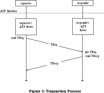 Figure 3–Transaction Process
Simple examples of transactions are:
• read a counter, reset it and send back the value read
• read six sectors of a disk and send back the data read
• write the data sent in the TReq to a printer
A basic assumption of the transaction model is that the amount of ATP data sent in the TReq specifying the operation to be performed is small enough to fit in a single datagram. A TResp, on the other hand, may span several datagrams, as in the second example. Thus, a TReq is a single datagram, while a TResp consists of up to eight datagrams, each of which is assigned a sequence number from 0 to 7 to indicate its position in the response.
The requester must, before calling for a TReq to be sent, set aside enough buffer space to receive the datagram(s) of the TResp. The number of buffers allocated (in other words, the maximum number of datagrams that the responder can send) is indicated in the TReq by an eight-bit bit map. The bits of this bit map are numbered 0 to 7 (the least significant bit being number 0); each bit corresponds to the response datagram with the respective sequence number.
_______________________________________________________________________________
»Datagram Loss Recovery
The way that ATP recovers from datagram loss situations is best explained by an example; see Figure 4. Assume that the requester wants to read six sectors of 512 bytes each from the responder’s disk. The requester puts aside six 512-byte buffers (which may or may not be contiguous) for the response datagrams, and calls ATP to send a TReq. In this TReq the bit map is set to binary 00111111 or decimal 63. The TReq carries a 16-bit transaction ID, generated by the requester’s .ATP driver before sending it. (This example assumes that the requester and responder have already agreed that each buffer can hold 512
bytes.) The TReq is delivered to the responder, which reads the six disk sectors and sends them back, through ATP, in TResp datagrams bearing sequence numbers 0 through 5. Each TResp datagram also carries exactly the same transaction ID as the TReq to which they’re responding.
There are several ways that datagrams may be lost in this case. The original TReq could be lost for one of many reasons. The responding node might be too busy to receive the TReq or might be out of buffers for receiving it, there could be an undetected collision on the network, a bit error in the transmission line, and so on. To recover from such errors, the requester’s .ATP driver maintains an ATP retry timer for each transaction sent. If this timer expires and the complete TResp has not been received, the TReq is retransmitted and the retry timer is restarted.
A second error situation occurs when one or more of the TResp datagrams isn’t received correctly by the requester’s .ATP driver (datagram 1 in Figure 4). Again, the retry timer will expire and the complete TResp will not have been received; this will result in a retransmission of the TReq. However, to avoid unnecessary retransmission of the TResp datagrams already properly received, the bit map of this retransmitted TReq is modified to reflect only those datagrams not yet received. Upon receiving this TReq, the responder retransmits only the missing response datagrams.
Another possible failure is that the responder’s .ATP driver goes down or the responder becomes unreachable through the underlying network system. In this case, retransmission of the TReq could continue indefinitely. To avoid this situation, the requester provides a maximum retry count; if this count is exceeded, the requester’s .ATP driver returns an appropriate error message to the requester.
Figure 3–Transaction Process
Simple examples of transactions are:
• read a counter, reset it and send back the value read
• read six sectors of a disk and send back the data read
• write the data sent in the TReq to a printer
A basic assumption of the transaction model is that the amount of ATP data sent in the TReq specifying the operation to be performed is small enough to fit in a single datagram. A TResp, on the other hand, may span several datagrams, as in the second example. Thus, a TReq is a single datagram, while a TResp consists of up to eight datagrams, each of which is assigned a sequence number from 0 to 7 to indicate its position in the response.
The requester must, before calling for a TReq to be sent, set aside enough buffer space to receive the datagram(s) of the TResp. The number of buffers allocated (in other words, the maximum number of datagrams that the responder can send) is indicated in the TReq by an eight-bit bit map. The bits of this bit map are numbered 0 to 7 (the least significant bit being number 0); each bit corresponds to the response datagram with the respective sequence number.
_______________________________________________________________________________
»Datagram Loss Recovery
The way that ATP recovers from datagram loss situations is best explained by an example; see Figure 4. Assume that the requester wants to read six sectors of 512 bytes each from the responder’s disk. The requester puts aside six 512-byte buffers (which may or may not be contiguous) for the response datagrams, and calls ATP to send a TReq. In this TReq the bit map is set to binary 00111111 or decimal 63. The TReq carries a 16-bit transaction ID, generated by the requester’s .ATP driver before sending it. (This example assumes that the requester and responder have already agreed that each buffer can hold 512
bytes.) The TReq is delivered to the responder, which reads the six disk sectors and sends them back, through ATP, in TResp datagrams bearing sequence numbers 0 through 5. Each TResp datagram also carries exactly the same transaction ID as the TReq to which they’re responding.
There are several ways that datagrams may be lost in this case. The original TReq could be lost for one of many reasons. The responding node might be too busy to receive the TReq or might be out of buffers for receiving it, there could be an undetected collision on the network, a bit error in the transmission line, and so on. To recover from such errors, the requester’s .ATP driver maintains an ATP retry timer for each transaction sent. If this timer expires and the complete TResp has not been received, the TReq is retransmitted and the retry timer is restarted.
A second error situation occurs when one or more of the TResp datagrams isn’t received correctly by the requester’s .ATP driver (datagram 1 in Figure 4). Again, the retry timer will expire and the complete TResp will not have been received; this will result in a retransmission of the TReq. However, to avoid unnecessary retransmission of the TResp datagrams already properly received, the bit map of this retransmitted TReq is modified to reflect only those datagrams not yet received. Upon receiving this TReq, the responder retransmits only the missing response datagrams.
Another possible failure is that the responder’s .ATP driver goes down or the responder becomes unreachable through the underlying network system. In this case, retransmission of the TReq could continue indefinitely. To avoid this situation, the requester provides a maximum retry count; if this count is exceeded, the requester’s .ATP driver returns an appropriate error message to the requester.
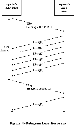 Figure 4–Datagram Loss Recovery
Note: There may be situations where, due to an anticipated delay, you’ll
want a request to be retransmitted more than 255 times; specifying a
retry count of 255 indicates “infinite retries” to ATP and will cause
a message to be retransmitted until the request has either been
serviced, or been cancelled through a specific call.
Finally, in our example, what if the responder is able to provide only four disk sectors (having reached the end of the disk) instead of the six requested? To handle this situation, there’s an end-of-message (EOM) flag in each TResp datagram. In this case, the TResp datagram numbered 3 would come with this flag set. The reception of this datagram informs the requester’s .ATP driver that TResps numbered 4 and 5 will not be sent and should not be expected.
When the transaction completes successfully (all expected TResp datagrams are received or TResp datagrams numbered 0 to n are received with datagram n’s EOM flag set), the requester is informed and can then use the data received in the TResp.
ATP provides two classes of service: at-least-once (ALO) and exactly-once (XO). The TReq datagram contains an XO flag that’s set if XO service is required and cleared if ALO service is adequate. The main difference between the two is in the sequence of events that occurs when the TReq is received by the responder’s .ATP driver.
In the case of ALO service, each time a TReq is received (with the XO flag cleared), it’s delivered to the responder by its .ATP driver; this is true even for retransmitted TReqs of the same transaction. Each time the TReq is delivered, the responder performs the requested operation and sends the necessary TResp datagrams. Thus, the requested operation is performed at least once, and perhaps several times, until the transaction is completed at the requester’s end.
The at-least-once service is satisfactory in a variety of situations—for instance, if the requester wishes to read a clock or a counter being maintained at the responder’s end. However, in other circumstances, repeated execution of the requested operation is unacceptable. This is the case, for instance, if the requester is sending data to be printed at the responding end; exactly-once service is designed for such situations.
The responder’s .ATP driver maintains a transactions list of recently received XO TReqs. Whenever a TReq is received with its XO flag set, the driver goes through this list to see if this is a retransmitted TReq. If it’s the first TReq of a transaction, it’s entered into the list and delivered to the responder. The responder executes the requested operation and calls its driver to send a TResp. Before sending it out, the .ATP driver saves the TResp in the list.
When a retransmitted TReq for the same XO transaction is received, the responder’s .ATP driver will find a corresponding entry in the list. The retransmitted TReq is not delivered to the responder; instead, the driver automatically retransmits the response datagrams that were saved in the list. In this way, the responder never sees the retransmitted TReqs and the requested operation is performed only once.
ATP must include a mechanism for eventually removing XO entries from the responding end’s transaction list; two provisions are made for this. When the requester’s .ATP driver has received all the TResp datagrams of a particular transaction, it sends a datagram known as a transaction release (TRel); this tells the responder’s .ATP driver to remove the transaction from the list. However, the TRel could be lost in the network (or the responding end may die, and so on), leaving the entry in the list forever. To account for this situation, the responder’s .ATP driver maintains a release timer for each transaction. If this timer expires and no activity has occurred for the transaction, its entry is removed from the transactions list.
_______________________________________________________________________________
»ABOUT THE APPLETALK MANAGER
_______________________________________________________________________________
The AppleTalk Manager is divided into three parts (see Figure 5):
• A lower-level driver called “.MPP” that contains code to implement ALAP,
DDP, NBP, and the RTMP stub; this includes separate code resources loaded
in when an NBP name is registered or looked up.
• A higher-level driver called “.ATP” that implements ATP.
• A Pascal interface to these two drivers, which is a set of Pascal data
types and routines to aid Pascal programmers in calling the AppleTalk
Manager.
Figure 4–Datagram Loss Recovery
Note: There may be situations where, due to an anticipated delay, you’ll
want a request to be retransmitted more than 255 times; specifying a
retry count of 255 indicates “infinite retries” to ATP and will cause
a message to be retransmitted until the request has either been
serviced, or been cancelled through a specific call.
Finally, in our example, what if the responder is able to provide only four disk sectors (having reached the end of the disk) instead of the six requested? To handle this situation, there’s an end-of-message (EOM) flag in each TResp datagram. In this case, the TResp datagram numbered 3 would come with this flag set. The reception of this datagram informs the requester’s .ATP driver that TResps numbered 4 and 5 will not be sent and should not be expected.
When the transaction completes successfully (all expected TResp datagrams are received or TResp datagrams numbered 0 to n are received with datagram n’s EOM flag set), the requester is informed and can then use the data received in the TResp.
ATP provides two classes of service: at-least-once (ALO) and exactly-once (XO). The TReq datagram contains an XO flag that’s set if XO service is required and cleared if ALO service is adequate. The main difference between the two is in the sequence of events that occurs when the TReq is received by the responder’s .ATP driver.
In the case of ALO service, each time a TReq is received (with the XO flag cleared), it’s delivered to the responder by its .ATP driver; this is true even for retransmitted TReqs of the same transaction. Each time the TReq is delivered, the responder performs the requested operation and sends the necessary TResp datagrams. Thus, the requested operation is performed at least once, and perhaps several times, until the transaction is completed at the requester’s end.
The at-least-once service is satisfactory in a variety of situations—for instance, if the requester wishes to read a clock or a counter being maintained at the responder’s end. However, in other circumstances, repeated execution of the requested operation is unacceptable. This is the case, for instance, if the requester is sending data to be printed at the responding end; exactly-once service is designed for such situations.
The responder’s .ATP driver maintains a transactions list of recently received XO TReqs. Whenever a TReq is received with its XO flag set, the driver goes through this list to see if this is a retransmitted TReq. If it’s the first TReq of a transaction, it’s entered into the list and delivered to the responder. The responder executes the requested operation and calls its driver to send a TResp. Before sending it out, the .ATP driver saves the TResp in the list.
When a retransmitted TReq for the same XO transaction is received, the responder’s .ATP driver will find a corresponding entry in the list. The retransmitted TReq is not delivered to the responder; instead, the driver automatically retransmits the response datagrams that were saved in the list. In this way, the responder never sees the retransmitted TReqs and the requested operation is performed only once.
ATP must include a mechanism for eventually removing XO entries from the responding end’s transaction list; two provisions are made for this. When the requester’s .ATP driver has received all the TResp datagrams of a particular transaction, it sends a datagram known as a transaction release (TRel); this tells the responder’s .ATP driver to remove the transaction from the list. However, the TRel could be lost in the network (or the responding end may die, and so on), leaving the entry in the list forever. To account for this situation, the responder’s .ATP driver maintains a release timer for each transaction. If this timer expires and no activity has occurred for the transaction, its entry is removed from the transactions list.
_______________________________________________________________________________
»ABOUT THE APPLETALK MANAGER
_______________________________________________________________________________
The AppleTalk Manager is divided into three parts (see Figure 5):
• A lower-level driver called “.MPP” that contains code to implement ALAP,
DDP, NBP, and the RTMP stub; this includes separate code resources loaded
in when an NBP name is registered or looked up.
• A higher-level driver called “.ATP” that implements ATP.
• A Pascal interface to these two drivers, which is a set of Pascal data
types and routines to aid Pascal programmers in calling the AppleTalk
Manager.
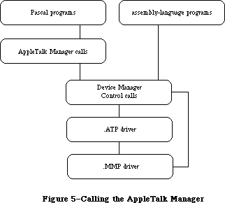 Figure 5–Calling the AppleTalk Manager
The two drivers and the interface to them are not in ROM; your application must link to the appropriate object files.
Pascal programmers make calls to the AppleTalk Manager’s Pascal interface, which in turn makes Device Manager Control calls to the two drivers. Assembly-language programmers make Device Manager Control calls directly to the drivers.
Note: Pascal programmers can, of course, make PBControl calls directly
if they wish.
The AppleTalk Manager provides ALAP routines that allow a program to:
• send a frame to another node
• receive a frame from another node
• add a protocol handler to the protocol handler table
• remove a protocol handler from the protocol handler table
Each node may have up to four protocol handlers in its protocol handler table, two of which are currently used by DDP.
By calling DDP, socket clients can:
• send a datagram via a socket
• receive a datagram via a socket
• open a socket and add a socket listener to the socket table
• close a socket and remove a socket listener from the socket table
Each node may have up to 12 open sockets in its socket table.
Programs cannot access RTMP directly via the AppleTalk Manager; RTMP exists solely for the purpose of providing DDP with routing information.
The NBP code allows a socket client to:
• register the name and socket number of an entity in the node’s names table
• determine the address (and confirm the existence) of an entity
• delete the name of an entity from the node’s names table
The AppleTalk Manager’s .ATP driver allows a socket client to do the following:
• open a responding socket to receive requests
• send a request to another socket and get back a response
• receive a request via a responding socket
• send a response via a responding socket
• close a responding socket
Note: Although the AppleTalk Manager provides four different protocols
for your use, you’re not bound to use all of them. In fact, most
programmers will use only the NBP and ATP protocols.
AppleTalk communicates via channel B of the Serial Communications Controller
(SCC). When the Macintosh is started up with a disk containing the AppleTalk code, the status of serial port B is checked. If port B isn’t being used by another device driver, and is available for use by AppleTalk, the .MPP driver is loaded into the system heap. On a Macintosh 128K, only the MPP code is loaded at system startup; the .ATP driver and NBP code are read into the application heap when the appropriate commands are issued. On a Macintosh 512K or XL, all AppleTalk code is loaded into the system heap at system startup.
After loading the AppleTalk code, the .MPP driver installs its own interrupt handlers, installs a task into the vertical retrace queue, and prepares the SCC for use. It then chooses a node ID for the Macintosh and confirms that the node ID isn’t already being used by another node on the network.
Warning: For this reason it’s imperative that the Macintosh be connected
to the AppleTalk network through serial port B (the printer port)
before being switched on.
The AppleTalk Manager also provides Pascal routines for opening and closing the .MPP and .ATP drivers. The open calls allow a program to load AppleTalk code at times other than system startup. The close calls allow a program to remove the AppleTalk code from the Macintosh; the use of close calls is highly discouraged, since other co-resident programs are then “disconnected” from AppleTalk. Both sets of calls are described in detail under “Calling the AppleTalk Manager from Pascal”.
Warning: If, at system startup, serial port B isn’t available for use by
AppleTalk, the .MPP driver won’t open. However, a driver doesn’t
return an error message when it fails to open. Pascal programmers
must ensure the proper opening of AppleTalk by calling one of the
two routines for opening the AppleTalk drivers (either MPPOpen or
ATPLoad). If AppleTalk was successfully loaded at system startup,
these calls will have no effect; otherwise they’ll check the
availability of port B, attempt to load the AppleTalk code, and
return an appropriate result code.
Assembly-language note: Assembly-language programmers can use the Pascal
routines for opening AppleTalk. They can also check
the availability of port B themselves and then decide
whether to open MPP or ATP. Detailed information on
how to do this is provided in the section “Calling
the AppleTalk Manager from Assembly Language”.
The two AppleTalk device drivers, named .MPP and .ATP, are included in the 128K ROM. The AppleTalk Manager, however (the interface to the drivers), is not in ROM; your application must link to the appropriate object files.
On the Macintosh Plus, you need only open the .MPP driver; this will also load the .ATP driver and NBP code automatically. Since, in the 128K ROM, device drivers return errors, it’s no longer necessary to check whether port B is free and configured for AppleTalk. If port B isn’t available, the .MPP driver won’t open and the result code portInUse or portNotCf will be returned.
Assembly-language note: When called from assembly language, the Datagram
Delivery Protocol (DDP) allows 14 (instead of 12)
open sockets.
The changes to the AppleTalk manager increase functionality and resources. Two interfaces for the AppleTalk Manager calls are discussed: the new or preferred interface and the alternate interface. Picking a node address in the server range, sending packets to one’s own node, multiple concurrent NBP requests, sending ATP requests through a specified socket and two new ATP calls are also discussed in this section. These calls can only be made with the preferred interface.
_______________________________________________________________________________
»CALLING THE APPLETALK MANAGER FROM PASCAL
_______________________________________________________________________________
This section discusses how to use the AppleTalk Manager from Pascal. Equivalent assembly-language information is given in the “Calling the AppleTalk Manager from Assembly Language” section.
You can execute many AppleTalk Manager routines either synchronously (meaning that the application can’t continue until the routine is completed) or asynchronously (meaning that the application is free to perform other tasks while the routine is being executed).
When an application calls an AppleTalk Manager routine asynchronously, an I/O request is placed in the appropriate driver’s I/O queue, and control returns to the calling program—possibly even before the actual I/O is completed. Requests are taken from the queue one at a time, and processed; meanwhile, the calling program is free to work on other things.
The routines that can be executed asynchronously contain a Boolean parameter called async. If async is TRUE, the call is executed asynchronously; otherwise the call is executed synchronously. Every time an asynchronous routine call is completed, the AppleTalk Manager posts a network event. The message field of the event record will contain a handle to the parameter block that was used to make that call.
Most AppleTalk Manager routines return an integer result code of type OSErr. Each routine description lists all of the applicable result codes generated by the AppleTalk Manager, along with a short description of what the result code means. Lengthier explanations of all the result codes can be found in the summary at the end of the chapter. Result codes from other parts of the Operating System may also be returned. (See Appendix A for a list of all result codes.)
Many Pascal calls to the AppleTalk Manager require information passed in a parameter block of type ABusRecord. The exact content of an ABusRecord depends on the protocol being called:
TYPE ABProtoType = (lapProto,ddpProto,nbpProto,atpProto);
ABusRecord = RECORD
abOpcode: ABCallType; {type of call}
abResult: INTEGER; {result code}
abUserReference: LONGINT; {for your use}
CASE ABProtoType OF
lapProto:
. . . {ALAP parameters}
ddpProto:
. . . {DDP parameters}
nbpProto:
. . . {NBP parameters}
atpProto:
. . . {ATP parameters}
END;
END;
ABRecPtr = ^ABusRecord;
ABRecHandle = ^ABRecPtr;
The value of the abOpcode field is inserted by the AppleTalk Manager when the call is made, and is always a member of the following set:
TYPE ABCallType = (tLAPRead,tLAPWrite,tDDPRead,tDDPWrite,tNBPLookup,
tNBPConfirm,tNBPRegister,tATPSndRequest,
tATPGetRequest,tATPSdRsp,tATPAddRsp,tATPRequest,
tATPRespond);
The abUserReference field is available for use by the calling program in any way it wants. This field isn’t used by the AppleTalk Manager routines or drivers.
The size of an ABusRecord data structure in bytes is given by one of the following constants:
CONST lapSize = 20;
ddpSize = 26;
nbpSize = 26;
atpSize = 56;
Variables of type ABusRecord must be allocated in the heap with Memory Manager NewHandle calls. For example:
myABRecord := ABRecHandle(NewHandle(ddpSize))
Warning: These Memory Manager calls can’t be made inside interrupts.
Routines that are executed asynchronously return control to the calling program with the result code noErr as soon as the call is placed in the driver’s I/O queue. This isn’t an indication of successful call completion; it simply indicates that the call was successfully queued to the appropriate driver. To determine when the call is actually completed, you can either check for a network event or poll the abResult field of the call’s ABusRecord. The abResult field, set to 1 when the call is made, receives the actual result code upon completion of the call.
Warning: A data structure of type ABusRecord is often used by the AppleTalk
Manager during an asynchronous call, and so is locked by the
AppleTalk Manager. Don’t attempt to unlock or use such a variable.
Each routine description includes a list of the ABusRecord fields affected by the routine. The arrow next to each field name indicates whether it’s an input, output, or input/output parameter:
Arrow Meaning
--> Parameter is passed to the routine
<-- Parameter is returned by the routine
<-> Parameter is passed to and returned by the routine
_______________________________________________________________________________
»Opening and Closing AppleTalk
X-Ref: Technical Note #224
FUNCTION MPPOpen : OSErr; [Not in ROM]
MPPOpen first checks whether the .MPP driver has already been loaded; if it has, MPPOpen does nothing and returns noErr. If MPP hasn’t been loaded, MPPOpen attempts to load it into the system heap. If it succeeds, it then initializes the driver’s variables and goes through the process of dynamically assigning a node ID to that Macintosh. On a Macintosh 512K or XL, it also loads the .ATP driver and NBP code into the system heap.
If serial port B isn’t configured for AppleTalk, or is already in use, the .MPP driver isn’t loaded and an appropriate result code is returned.
Result codes noErr No error
portInUse Port B is already in use
portNotCf Port B not configured for AppleTalk
FUNCTION MPPClose : OSErr; [Not in ROM]
MPPClose removes the .MPP driver, and any data structures associated with it, from memory. If the .ATP driver or NBP code were also installed, they’re removed as well. MPPClose also returns the use of port B to the Serial Driver.
Warning: Since other co-resident programs may be using AppleTalk, it’s
strongly recommended that you never use this call. MPPClose will
completely disable AppleTalk; the only way to restore AppleTalk
is to call MPPOpen again.
_______________________________________________________________________________
»AppleTalk Link Access Protocol
»Data Structures
ALAP calls use the following ABusRecord fields:
lapProto:
(lapAddress: LAPAdrBlock; {destination or source node ID}
lapReqCount: INTEGER; {length of frame data or buffer size in bytes}
lapActCount: INTEGER; {number of frame data bytes actually received}
lapDataPtr: Ptr); {pointer to frame data or pointer to buffer}
When an ALAP frame is sent, the lapAddress field indicates the ID of the destination node. When an ALAP frame is received, lapAddress returns the ID of the source node. The lapAddress field also indicates the ALAP protocol type of the frame:
TYPE LAPAdrBlock = PACKED RECORD
dstNodeID: Byte; {destination node ID}
srcNodeID: Byte; {source node ID}
lapProtType: ABByte {ALAP protocol type}
END;
When an ALAP frame is sent, lapReqCount indicates the size of the frame data in bytes and lapDataPtr points to a buffer containing the frame data to be sent. When an ALAP frame is received, lapDataPtr points to a buffer in which the incoming data can be stored and lapReqCount indicates the size of the buffer in bytes. The number of bytes actually sent or received is returned in the lapActCount field.
Each ALAP frame contains an eight-bit ALAP protocol type in the header. ALAP protocol types 128 through 255 are reserved for internal use by ALAP, hence the declaration:
TYPE ABByte = 1..127; {ALAP protocol type}
Warning: Don’t use ALAP protocol type values 1 and 2; they’re reserved
for use by DDP. Value 3 through 15 are reserved for internal
use by Apple and also shouldn’t be used.
»Using ALAP
Most programs will never need to call ALAP, because higher-level protocols will automatically call it as necessary. If you do want to send a frame directly via ALAP, call the LAPWrite function. If you want to read ALAP frames, you have two choices:
• Call LAPOpenProtocol with NIL for protoPtr (see below); this installs
the default protocol handler provided by the AppleTalk Manager. Then
call LAPRead to receive frames.
• Write your own protocol handler, and call LAPOpenProtocol to add it
to the node’s protocol handler table. The ALAP code will examine every
incoming frame and send all those with the correct ALAP protocol type
to your protocol handler. See the section “Protocol Handlers and Socket
Listeners” for information on how to write a protocol handler.
When your program no longer wants to receive frames with a particular ALAP protocol type value, it can call LAPCloseProtocol to remove the corresponding protocol handler from the protocol handler table.
»ALAP Routines
FUNCTION LAPOpenProtocol (theLAPType: ABByte;
protoPtr: Ptr) : OSErr; [Not in ROM]
LAPOpenProtocol adds the ALAP protocol type specified by theLAPType to the
node’s protocol table. If you provide a pointer to a protocol handler in protoPtr, ALAP will send each frame with an ALAP protocol type of theLAPType to that protocol handler.
If protoPtr is NIL, the default protocol handler will be used for receiving frames with an ALAP protocol type of theLAPType. In this case, to receive a frame you must call LAPRead to provide the default protocol handler with a buffer for placing the data. If, however, you’ve written your own protocol handler and protoPtr points to it, your protocol handler will have the responsibility for receiving the frame and it’s not necessary to call LAPRead.
Result codes noErr No error
lapProtErr Error attaching protocol type
FUNCTION LAPCloseProtocol (theLAPType: ABByte) : OSErr; [Not in ROM]
LAPCloseProtocol removes from the node’s protocol table the specified ALAP protocol type, as well as its protocol handler.
Warning: Don’t close ALAP protocol type values 1 or 2. If you close these
protocol types, DDP will be disabled; once disabled, the only way
to restore DDP is to restart the system, or to close and then
reopen AppleTalk.
Result codes noErr No error
lapProtErr Error detaching protocol type
FUNCTION LAPWrite (abRecord: ABRecHandle;
async: BOOLEAN) : OSErr; [Not in ROM]
ABusRecord
<-- abOpcode {always tLAPWrite}
<-- abResult {result code}
--> abUserReference {for your use}
--> lapAddress.dstNodeID {destination node ID}
--> lapAddress.lapProtType {ALAP protocol type}
--> lapReqCount {length of frame data}
--> lapDataPtr {pointer to frame data}
LAPWrite sends a frame to another node. LAPReqCount and lapDataPtr specify the length and location of the data to send. The lapAddress.lapProtType field indicates the ALAP protocol type of the frame and the lapAddress.dstNodeID indicates the node ID of the node to which the frame should be sent.
Note: The first two bytes of an ALAP frame’s data must contain the length
in bytes of that data, including the length bytes themselves.
Result codes noErr No error
excessCollsns Unable to contact destination node;
packet not sent
ddpLenErr ALAP data length too big
lapProtErr Invalid ALAP protocol type
FUNCTION LAPRead (abRecord: ABRecHandle;
async: BOOLEAN) : OSErr; [Not in ROM]
ABusRecord
<-- abOpcode {always tLAPRead}
<-- abResult {result code}
--> abUserReference {for your use}
<-- lapAddress.dstNodeID {destination node ID}
<-- lapAddress.srcNodeID {source node ID}
--> lapAddress.lapProtType {ALAP protocol type}
--> lapReqCount {buffer size in bytes}
<-- lapActCount {number of frame data bytes actually received}
--> lapDataPtr {pointer to buffer}
LAPRead receives a frame from another node. LAPReqCount and lapDataPtr specify the size and location of the buffer that will receive the frame data. If the buffer isn’t large enough to hold all of the incoming frame data, the extra bytes will be discarded and buf2SmallErr will be returned. The number of bytes actually received is returned in lapActCount. Only frames with ALAP protocol type equal to lapAddress.lapProtType will be received. The node IDs of the frame’s source and destination nodes are returned in lapAddress.srcNodeID and lapAddress.dstNodeID. You can determine whether the packet was broadcast to you by examining the value of lapAddress.dstNodeID—if the packet was broadcast it’s equal to 255, otherwise it’s equal to your node ID.
Note: You should issue LAPRead calls only for ALAP protocol types that were
opened (via LAPOpenProtocol) to use the default protocol handler.
Warning: If you close a protocol type for which there are still LAPRead
calls pending, the calls will be canceled but the memory occupied
by their ABusRecords will not be released. For this reason, before
closing a protocol type, call LAPRdCancel to cancel any pending
LAPRead calls associated with that protocol type.
Result codes noErr No error
buf2SmallErr Frame too large for buffer
readQErr Invalid protocol type or protocol type not
found in table
FUNCTION LAPRdCancel (abRecord: ABRecHandle) : OSErr; [Not in ROM]
Given the handle to the ABusRecord of a previously made LAPRead call, LAPRdCancel dequeues the LAPRead call, provided that a packet satisfying the LAPRead has not already arrived. LAPRdCancel returns noErr if the LAPRead call is successfully removed from the queue. If LAPRdCancel returns recNotFnd, check the abResult field to verify that the LAPRead has been completed and determine its outcome.
Result codes noErr No error
readQErr Invalid protocol type or protocol type not
found in table
recNotFnd ABRecord not found in queue
»Example
This example sends an ALAP packet synchronously and waits asynchronously for a response. Assume that both nodes are using a known protocol type (in this case, 73) to receive packets, and that the destination node has a node ID of 4.
VAR
myABRecord: ABRecHandle;
myBuffer: PACKED ARRAY [0..599] OF CHAR; {buffer for both send and receive}
myLAPType: Byte;
errCode, index, dataLen: INTEGER;
someText: Str255;
async: BOOLEAN;
BEGIN
errCode := MPPOpen;
IF errCode <> noErr THEN
WRITELN('Error in opening AppleTalk')
{Maybe serial port B isn't available for use by AppleTalk}
ELSE
BEGIN
{Call Memory Manager to allocate ABusRecord}
myABRecord := ABRecHandle(NewHandle(lapSize));
myLAPType := 73;
{Enter myLAPType into protocol handler table and install default handler to }
{ service frames of that ALAP type. No packets of that ALAP type will be }
{ received until we call LAPRead.}
errCode := LAPOpenProtocol(myLAPType, NIL);
IF errCode <> noErr THEN
WRITELN('Error while opening the protocol type')
{Have we opened too many protocol types? Remember that DDP uses two of }
{ them.}
ELSE
BEGIN
{Prepare data to be sent}
someText := 'This data will be in the ALAP data area';
{The .MPP implementation requires that the first two bytes of the ALAP }
{ data field contain the length of the data, including the length bytes }
{ themselves.}
dataLen := LENGTH(someText) + 2;
buffer[0] := CHR(dataLen DIV 256); {high byte of data length}
buffer[1] := CHR(dataLen MOD 256); {low byte of data length}
FOR index := 1 TO dataLen - 2 DO {stuff buffer with packet data}
buffer[index + 1] := someText[index];
async := FALSE;
WITH myABRecord^^ DO {fill parameters in the ABusRecord}
BEGIN
lapAddress.lapProtType := myLAPType;
lapAddress.dstNodeID := 4;
lapReqCount := dataLen;
lapDataPtr := @buffer;
END;
{Send the frame}
errCode := LAPWrite(myABRecord, async);
{In the case of a sync call, errCode and the abResult field of }
{ the myABRecord will contain the same result code. We can also }
{ reuse myABRecord, since we know whether the call has completed.}
IF errCode <> noErr THEN
WRITELN('Error while writing out the packet')
{Maybe the receiving node wasn't on-line}
ELSE
BEGIN
{We have sent out the packet and are now waiting for a response. We }
{ issue an async LAPRead call so that we don't “hang” waiting for a }
{ response that may not come.}
async := TRUE;
WITH myABRecord^^ DO
BEGIN
lapAddress.lapProtType := myLAPType;
{ALAP type we want to receive }
lapReqCount := 600; {our buffer is maximum size}
lapDataPtr := @buffer;
END;
errCode := LAPRead(myABRecord, async); {wait for a packet}
IF errCode <> noErr THEN
WRITELN('Error while trying to queue up a LAPRead')
{Was the protocol handler installed correctly?}
ELSE
BEGIN
{We can either sit here in a loop and poll the abResult }
{ field or just exit our code and use the event }
{ mechanism to flag us when the packet arrives.}
CheckForMyEvent; {your procedure for checking for a network event}
errCode := LAPCloseProtocol(myLAPType);
IF errCode <> noErr THEN
WRITELN('Error while closing the protocol type');
END;
END;
END;
END;
END.
_______________________________________________________________________________
»Datagram Delivery Protocol
»Data Structures
DDP calls use the following ABusRecord fields:
ddpProto:
(ddpType: Byte; {DDP protocol type}
ddpSocket: Byte; {source or listening socket number}
ddpAddress: AddrBlock; {destination or source socket address}
ddpReqCount: INTEGER; {length of datagram data or buffer size in bytes}
ddpActCount: INTEGER; {number of bytes actually received}
ddpDataPtr: Ptr; {pointer to buffer}
ddpNodeID: Byte); {original destination node ID}
When a DDP datagram is sent, ddpReqCount indicates the size of the datagram data in bytes and ddpDataPtr points to a buffer containing the datagram data. DDPSocket specifies the socket from which the datagram should be sent. DDPAddress is the internet address of the socket to which the datagram should be sent:
TYPE AddrBlock = PACKED RECORD
aNet: INTEGER; {network number}
aNode: Byte; {node ID}
aSocket: Byte {socket number}
END;
Note: The network number you specify in ddpAddress.aNet tells MPP whether
to create a long header (for an internet) or a short header (for a
local network only). A short DDP header will be sent if ddpAddress.aNet
is 0 or equal to the network number of the local network.
When a DDP datagram is received, ddpDataPtr points to a buffer in which the incoming data can be stored and ddpReqCount indicates the size of the buffer in bytes. The number of bytes actually sent or received is returned in the ddpActCount field. DDPAddress is the internet address of the socket from which the datagram was sent.
DDPType is the DDP protocol type of the datagram, and ddpSocket specifies the socket that will receive the datagram.
Warning: DDP protocol types 1 through 15 and DDP socket numbers 1 through 63
are reserved by Apple for internal use. Socket numbers 64 through 127
are available for experimental use. Use of these experimental sockets
isn’t recommended for commercial products, since there’s no mechanism
for eliminating conflicting usage by different developers.
»Using DDP
Before it can use a socket, the program must call DDPOpenSocket, which adds a socket and its socket listener to the socket table. When a program is finished using a socket, call DDPCloseSocket, which removes the socket’s entry from the socket table. To send a datagram via DDP, call DDPWrite. To receive datagrams, you have two choices:
• Call DDPOpenSocket with NIL for sktListener (see below); this installs
the default socket listener provided by the AppleTalk Manager. Then call
DDPRead to receive datagrams.
• Write your own socket listener and call DDPOpenSocket to install it. DDP
will call your socket listener for every incoming datagram for that
socket; in this case, you shouldn’t call DDPRead. For information on how
to write a socket listener, see the section “Protocol Handlers and Socket
Listeners”.
To cancel a previously issued DDPRead call (provided it’s still in the queue), call DDPRdCancel.
»DDP Routines
FUNCTION DDPOpenSocket (VAR theSocket: Byte;
sktListener: Ptr) : OSErr; [Not in ROM]
DDPOpenSocket adds a socket and its socket listener to the socket table. If theSocket is nonzero, it must be in the range 64 to 127, and it specifies the socket’s number; if theSocket is 0, DDPOpenSocket dynamically assigns a socket number in the range 128 to 254, and returns it in theSocket. SktListener contains a pointer to the socket listener; if it’s NIL, the default listener will be used.
If you’re using the default socket listener, you must then call DDPRead to receive a datagram (in order to specify buffer space for the default socket listener). If, however, you’ve written your own socket listener and sktListener points to it, your listener will provide buffers for receiving datagrams and you shouldn’t use DDPRead calls.
DDPOpenSocket will return ddpSktErr if you pass the number of an already opened socket, if you pass a socket number greater than 127, or if the socket table is full.
Note: The range of static socket numbers 1 through 63 is reserved by Apple
for internal use. Socket numbers 64 through 127 are available for
unrestricted experimental use.
Result codes noErr No error
ddpSktErr Socket error
FUNCTION DDPCloseSocket (theSocket: Byte) : OSErr; [Not in ROM]
DDPCloseSocket removes the entry of the specified socket from the socket table and cancels all pending DDPRead calls that have been made for that socket. If you pass a socket number of 0, or if you attempt to close a socket that isn’t open, DDPCloseSocket will return ddpSktErr.
Result codes noErr No error
ddpSktErr Socket error
FUNCTION DDPWrite (abRecord: ABRecHandle; doChecksum: BOOLEAN;
async: BOOLEAN) : OSErr; [Not in ROM]
ABusRecord
<-- abOpcode {always tDDPWrite}
<-- abResult {result code}
--> abUserReference {for your use}
--> ddpType {DDP protocol type}
--> ddpSocket {source socket number}
--> ddpAddress {destination socket address}
--> ddpReqCount {length of datagram data}
--> ddpDataPtr {pointer to buffer}
DDPWrite sends a datagram to another socket. DDPReqCount and ddpDataPtr specify the length and location of the data to send. The ddpType field indicates the DDP protocol type of the frame, and ddpAddress is the complete internet address of the socket to which the datagram should be sent. DDPSocket specifies the socket from which the datagram should be sent. Datagrams sent over the internet to a node on an AppleTalk network different from the sending node’s network have an optional software checksum to detect errors that might occur inside the intermediate bridges. If doChecksum is TRUE, DDPWrite will compute this checksum; if it’s FALSE, this software checksum feature is ignored.
Note: The destination socket can’t be in the same node as the program
making the DDPWrite call.
Result codes noErr No error
ddpLenErr Datagram length too big
ddpSktErr Source socket not open
noBridgeErr No bridge found
FUNCTION DDPRead (abRecord: ABRecHandle; retCksumErrs: BOOLEAN;
async: BOOLEAN) : OSErr; [Not in ROM]
ABusRecord
<-- abOpcode {always tDDPRead}
<-- abResult {result code}
--> abUserReference {for your use}
<-- ddpType {DDP protocol type}
--> ddpSocket {listening socket number}
<-- ddpAddress {source socket address}
--> ddpReqCount {buffer size in bytes}
<-- ddpActCount {number of bytes actually received}
--> ddpDataPtr {pointer to buffer}
<-- ddpNodeID {original destination node ID}
DDPRead receives a datagram from another socket. The size and location of the buffer that will receive the data are specified by ddpReqCount and ddpDataPtr. If the buffer isn’t large enough to hold all of the incoming frame data, the extra bytes will be discarded and buf2SmallErr will be returned. The number of bytes actually received is returned in ddpActCount. DDPSocket specifies the socket to receive the datagram (the “listening” socket). The node to which the packet was sent is returned in ddpNodeID; if the packet was broadcast ddpNodeID will contain 255. The address of the socket that sent the packet is returned in ddpAddress. If retCksumErrs is FALSE, DDPRead will discard any packets received with an invalid checksum and inform the caller of the error. If retCksumErrs is TRUE, DDPRead will deliver all packets, whether or not the checksum is valid; it will also notify the caller when there’s a checksum error.
Note: The sender of the datagram must be in a different node from the
receiver. You should issue DDPRead calls only for receiving datagrams
for sockets opened with the default socket listener; see the
description of DDPOpenSocket.
Note: If the buffer provided isn’t large enough to hold all of the incoming
frame data (buf2SmallErr), the checksum can’t be calculated; in this
case, DDPRead will deliver packets even if retCksumErrs is FALSE.
Result codes noErr No error
buf2SmallErr Datagram too large for buffer
cksumErr Checksum error
ddpLenErr Datagram length too big
ddpSktErr Socket error
readQErr Invalid socket or socket not found in table
FUNCTION DDPRdCancel (abRecord: ABRecHandle) : OSErr; [Not in ROM]
Given the handle to the ABusRecord of a previously made DDPRead call, DDPRdCancel dequeues the DDPRead call, provided that a packet satisfying the DDPRead hasn’t already arrived. DDPRdCancel returns noErr if the DDPRead call is successfully removed from the queue. If DDPRdCancel returns recNotFnd, check the abResult field of abRecord to verify that the DDPRead has been completed and determine its outcome.
Result codes noErr No error
readQErr Invalid socket or socket not found in table
recNotFnd ABRecord not found in queue
»Example
This example sends a DDP packet synchronously and waits asynchronously for a response. Assume that both nodes are using a known socket number (in this case, 30) to receive packets. Normally, you would want to use NBP to look up your destination’s socket address.
VAR
myABRecord: ABRecHandle;
myBuffer: PACKED ARRAY [0..599] OF CHAR; {buffer for both send and receive}
mySocket: Byte;
errCode, index, dataLen: INTEGER;
someText: Str255;
async, retCksumErrs, doChecksum: BOOLEAN;
BEGIN
errCode := MPPOpen;
IF errCode <> noErr THEN
WRITELN('Error in opening AppleTalk')
{Maybe serial port B isn't available for use by AppleTalk}
ELSE
BEGIN
{Call Memory Manager to allocate ABusRecord}
myABRecord := ABRecHandle(NewHandle(ddpSize));
mySocket := 30;
{Add mySocket to socket table and install default socket listener to service }
{ datagrams addressed to that socket. No packets addressed to mySocket will be }
{ received until we call DDPRead. }
errCode := DDPOpenSocket(mySocket, NIL);
IF errCode <> noErr THEN
WRITELN('Error while opening the socket')
{Have we opened too many socket listeners? Remember that DDP uses two of }
{ them.}
ELSE
BEGIN
{Prepare data to be sent}
someText := 'This is a sample datagram';
dataLen := LENGTH(someText);
FOR index := 0 TO dataLen - 1 DO {stuff buffer with packet data}
myBuffer[index] := someText[index + 1];
async := FALSE;
WITH myABRecord^^ DO {fill the parameters in the ABusRecord}
BEGIN
ddpType := 5;
ddpAddress.aNet := 0; {send on “our” network}
ddpAddress.aNode := 34;
ddpAddress.aSocket := mySocket;
ddpReqCount := dataLen;
ddpDataPtr := @myBuffer;
END;
doChecksum := FALSE;
{If packet contains a DDP long header, compute checksum and insert it into }
{ the header.}
errCode := DDPWrite(myABRecord, doChecksum, async); {send packet}
{In the case of a sync call, errCode and the abResult field of myABRecord }
{ will contain the same result code. We can also reuse myABRecord, since we }
{ know whether the call has completed.}
IF errCode <> noErr THEN
WRITELN('Error while writing out the packet')
{Maybe the receiving node wasn't on-line}
ELSE
BEGIN
{We have sent out the packet and are now waiting for a response. We }
{ issue an async DDPRead call so that we don't “hang” waiting for a }
{ response that may not come. To cancel the async read call, we must }
{ close the socket associated with the call or call DDPRdCancel.}
async := TRUE;
retCksumErrs := TRUE; {return packets even if }
{ they have a checksum error}
WITH myABRecord^^ DO
BEGIN
ddpSocket := mySocket;
ddpReqCount := 600; {our reception buffer is max size}
ddpDataPtr := @myBuffer;
END;
{Wait for a packet asynchronously}
errCode := DDPRead(myABRecord, retCksumErrs, async);
IF errCode <> noErr THEN
WRITELN('Error while trying to queue up a DDPRead')
{Was the socket listener installed correctly?}
ELSE
BEGIN
{We can either sit here in a loop and poll the }
{ abResult field or just exit our code and use the }
{ event mechanism to flag us when the packet arrives.}
CheckForMyEvent; {your procedure for checking for a }
{ network event}
{If there were no errors, a packet is inside the array }
{ mybuffer, the length is in ddpActCount, and the }
{ address of the sending socket is in ddpAddress. }
{ Process the packet received here and report any errors.}
errCode := DDPCloseSocket(mySocket); {we're done with it}
IF errCode <> noErr THEN
WRITELN('Error while closing the socket');
END;
END;
END;
END;
END.
_______________________________________________________________________________
»AppleTalk Transaction Protocol
»Data Structures
ATP calls use the following ABusRecord fields:
atpProto:
(atpSocket: Byte; {listening or responding socket number}
atpAddress: AddrBlock; {destination or source socket address}
atpReqCount: INTEGER; {request size or buffer size}
atpDataPtr: Ptr; {pointer to buffer}
atpRspBDSPtr: BDSPtr; {pointer to response BDS}
atpBitMap: BitMapType; {transaction bit map}
atpTransID: INTEGER; {transaction ID}
atpActCount: INTEGER; {number of bytes actually received}
atpUserData: LONGINT; {user bytes}
atpXO: BOOLEAN; {exactly-once flag}
atpEOM: BOOLEAN; {end-of-message flag}
atpTimeOut: Byte; {retry timeout interval in seconds}
atpRetries: Byte; {maximum number of retries}
atpNumBufs: Byte; {number of elements in response BDS or number }
{ of response packets sent}
atpNumRsp: Byte; {number of response packets received or }
{ sequence number}
atpBDSSize: Byte; {number of elements in response BDS}
atpRspUData: LONGINT; {user bytes sent or received in transaction }
{ response}
atpRspBuf: Ptr; {pointer to response message buffer}
atpRspSize: INTEGER); {size of response message buffer}
The socket receiving the request or sending the response is identified by atpSocket. ATPAddress is the address of either the destination or the source socket of a transaction, depending on whether the call is sending or receiving data, respectively. ATPDataPtr and atpReqCount specify the location and size
(in bytes) of a buffer that either contains a request or will receive a request. The number of bytes actually received in a request is returned in atpActCount. ATPTransID specifies the transaction ID. The transaction bit map is contained in atpBitMap, in the form:
TYPE BitMapType = PACKED ARRAY[0..7] OF BOOLEAN;
Each bit in the bit map corresponds to one of the eight possible packets in a response. For example, when a request is made for which five response packets are expected, the bit map sent is binary 00011111 or decimal 31. If the second packet in the response is lost, the requesting socket will retransmit the request with a bit map of binary 00000010 or decimal 2.
ATPUserData contains the user bytes of an ATP header. ATPXO is TRUE if the transaction is to be made with exactly-once service. ATPEOM is TRUE if the response packet is the last packet of a transaction. If the number of responses is less than the number that were requested, then ATPEOM must also be TRUE. ATPNumRsp contains either the number of responses received or the sequence number of a response.
The timeout interval in seconds and the maximum number of times that a request should be made are indicated by atpTimeOut and atpRetries, respectively.
Note: Setting atpRetries to 255 will cause the request to be retransmitted
indefinitely, until a full response is received or the call is canceled.
ATP provides a data structure, known as a response buffer data structure
(response BDS), for allocating buffer space to receive the datagram(s) of the response. A response BDS is an array of one to eight elements. Each BDS element defines the size and location of a buffer for receiving one response datagram; they’re numbered 0 to 7 to correspond to the sequence numbers of the response datagrams.
ATP needs a separate buffer for each response datagram expected, since packets may not arrive in the proper sequence. It does not, however, require you to set up and use the BDS data structure to describe the response buffers; if you
don’t, ATP will do it for you. Two sets of calls are provided for both requests and responses; one set requires you to allocate a response BDS and the other doesn’t.
Assembly-language note: The two calls that don’t require you to define a BDS
data structure (ATPRequest and ATPResponse) are
available in Pascal only.
The number of BDS elements allocated (in other words, the maximum number of datagrams that the responder can send) is indicated in the TReq by an eight-bit bit map. The bits of this bit map are numbered 0 to 7 (the least significant bit being number 0); each bit corresponds to the response datagram with the respective sequence number.
ATPRspBDSPtr and atpBDSSize indicate the location and number of elements in the response BDS, which has the following structure:
TYPE BDSElement =
RECORD
buffSize: INTEGER; {buffer size in bytes}
buffPtr: Ptr; {pointer to buffer}
dataSize: INTEGER; {number of bytes actually received}
userBytes: LONGINT {user bytes}
END;
BDSType = ARRAY[0..7] OF BDSElement; {response BDS}
BDSPtr = ^BDSType;
ATPNumBufs indicates the number of elements in the response BDS that contain information. In most cases, you can allocate space for your variables of BDSType statically with a VAR declaration. However, you can allocate only the minimum space required by your ATP calls by doing the following:
VAR myBDSPtr: BDSPtr;
. . .
numOfBDS := 3; {number of elements needed}
myBDSPtr := BDSPtr(NewPtr(SIZEOF(BDSElement) * numOfBDS));
Note: The userBytes field of the BDSElement and the atpUserData field
of the ABusRecord represent the same information in the datagram.
Depending on the ATP call made, one or both of these fields will be used.
»Using ATP
Before you can use ATP on a Macintosh 128K, the .ATP driver must be read from the system resource file via an ATPLoad call. The .ATP driver loads itself into the application heap and installs a task into the vertical retrace queue.
Warning: When another application starts up, the application heap is
reinitialized; on a Macintosh 128K, this means that the ATP
code is lost (and must be reloaded by the next application).
When you’re through using ATP on a Macintosh 128K, call ATPUnload—the system will be returned to the state it was in before the .ATP driver was opened.
On a Macintosh 512K or XL, the .ATP driver will have been loaded into the system heap either at system startup or upon execution of MPPOpen or ATPLoad. ATPUnload has no effect on a Macintosh 512K or XL.
To send a transaction request, call ATPSndRequest or ATPRequest. The .ATP driver will automatically select and open a socket through which the request datagram will be sent, and through which the response datagrams will be received. The requester must specify the full network address (network number, node ID, and socket number) of the socket to which the request is to be sent. This socket is known as the responding socket, and its address must be known in advance by the requester.
At the responder’s end, before a transaction request can be received, a responding socket must be opened, and the appropriate calls be made, to receive a request. To do this, the responder first makes an ATPOpenSocket call which allows the responder to specify the address (or part of it) of the requesters from whom it’s willing to accept transaction requests. Then it issues an ATPGetRequest call to provide ATP with a buffer for receiving a request; when a request is received, ATPGetRequest is completed. The responder can queue up several ATPGetRequest calls, each of which will be completed as requests are received.
Upon receiving a request, the responder performs the requested operation, and then prepares the information to be returned to the requester. It then calls ATPSndRsp (or ATPResponse) to send the response. Actually, the responder can issue the ATPSndRsp call with only part (or none) of the response specified. Additional portions of the response can be sent later by calling ATPAddRsp.
The ATPSndRsp and ATPAddRsp calls provide flexibility in the design (and range of types) of transaction responders. For instance, the responder may, for some reason, be forced to send the responses out of sequence. Also, there might be memory constraints that force sending the complete transaction response in parts. Even though eight response datagrams might need to be sent, the responder might have only enough memory to build one datagram at a time. In this case, it would build the first response datagram and call ATPSndRsp to send it. It would then build the second response datagram in the same buffer and call ATPAddRsp to send it; and so on, for the third through eighth response datagrams.
A responder can close a responding socket by calling ATPCloseSocket. This call cancels all pending ATP calls for that socket, such as ATPGetRequest, ATPSndRsp, and ATPResponse.
For exactly-once transactions, the ATPSndRsp and ATPAddRsp calls don’t terminate until the entire transaction has completed (that is, the responding end receives a release packet, or the release timer has expired).
To cancel a pending, asynchronous ATPSndRequest or ATPRequest call, call ATPReqCancel. To cancel a pending, asynchronous ATPSndRsp or ATPResponse call, call ATPRspCancel. Pending asynchronous ATPGetRequest calls can be canceled only by issuing the ATPCloseSocket call, but that will cancel all outstanding calls for that socket.
X-Ref: Technical Note #250
Warning: You cannot reuse a variable of type ABusRecord passed to an ATP
routine until the entire transaction has either been completed
or canceled.
»ATP Routines
FUNCTION ATPLoad : OSErr; [Not in ROM]
X-Ref: Technical Note #224
ATPLoad first verifies that the .MPP driver is loaded and running. If it isn’t, ATPLoad verifies that port B is configured for AppleTalk and isn’t in use, and then loads MPP into the system heap.
ATPLoad then loads the .ATP driver, unless it’s already in memory. On a Macintosh 128K, ATPLoad reads the .ATP driver from the system resource file into the application heap; on a Macintosh 512K or XL, ATP is read into the system heap.
Note: On a Macintosh 512K or XL, ATPLoad and MPPOpen perform essentially
the same function.
Result codes noErr No error
portInUse Port B is already in use
portNotCf Port B not configured for AppleTalk
FUNCTION ATPUnload : OSErr; [Not in ROM]
ATPUnload makes the .ATP driver purgeable; the space isn’t actually released by the Memory Manager until necessary.
Note: This call applies only to a Macintosh 128K; on a Macintosh 512K
or Macintosh XL, ATPUnload has no effect.
Result codes noErr No error
FUNCTION ATPOpenSocket (addrRcvd: AddrBlock;
VAR atpSocket: Byte) : OSErr; [Not in ROM]
ATPOpenSocket opens a socket for the purpose of receiving requests. ATPSocket contains the socket number of the socket to open; if it’s 0, a number is dynamically assigned and returned in atpSocket. AddrRcvd contains a filter of the sockets from which requests will be accepted. A 0 in the network number, node ID, or socket number field of the addrRcvd record acts as a “wild card”; for instance, a 0 in the socket number field means that requests will be accepted from all sockets in the node(s) specified by the network and node fields.
Result codes noErr No error
tooManySkts Socket table full
noDataArea Too many outstanding ATP calls
Note: If you’re only going to send requests and receive responses to
these requests, you don’t need to open an ATP socket. When you
make the ATPSndRequest or ATPRequest call, ATP automatically
opens a dynamically assigned socket for that purpose.
FUNCTION ATPCloseSocket (atpSocket: Byte) : OSErr; [Not in ROM]
ATPCloseSocket closes the responding socket whose number is specified by atpSocket. It releases the data structures associated with all pending, asynchronous calls involving that socket; these pending calls are completed immediately and return the result code sktClosed.
Result codes noErr No error
noDataArea Too many outstanding ATP calls
FUNCTION ATPSndRequest (abRecord: ABRecHandle;
async: BOOLEAN) : OSErr; [Not in ROM]
ABusRecord
<-- abOpcode {always tATPSndRequest}
<-- abResult {result code}
--> abUserReference {for your use}
--> atpAddress {destination socket address}
--> atpReqCount {request size in bytes}
--> atpDataPtr {pointer to buffer}
--> atpRspBDSPtr {pointer to response BDS}
--> atpUserData {user bytes}
--> atpXO {exactly-once flag}
<-- atpEOM {end-of-message flag}
--> atpTimeOut {retry timeout interval in seconds}
--> atpRetries {maximum number of retries}
--> atpNumBufs {number of elements in response BDS}
<-- atpNumRsp {number of response packets actually received}
ATPSndRequest sends a request to another socket. ATPAddress is the internet address of the socket to which the request should be sent. ATPDataPtr and atpReqCount specify the location and size of a buffer that contains the request information to be sent. ATPUserData contains the user bytes for the ATP header.
ATPSndRequest requires you to allocate a response BDS. ATPRspBDSPtr is a pointer to the response BDS; atpNumBufs indicates the number of elements in the BDS (this is also the maximum number of response datagrams that will be accepted). The number of response datagrams actually received is returned in atpNumRsp; if a nonzero value is returned, you can examine the response BDS to determine which packets of the transaction were actually received. If the number returned is less than requested, one of the following is true:
• Some of the packets have been lost and the retry count has been exceeded.
• ATPEOM is TRUE; this means that the response consisted of fewer packets
than were expected, but that all packets sent were received (the last
packet came with the atpEOM flag set).
ATPTimeOut indicates the length of time that ATPSndRequest should wait for a response before retransmitting the request. ATPRetries indicates the maximum number of retries ATPSndRequest should attempt. ATPXO should be TRUE if you want the request to be part of an exactly-once transaction.
ATPSndRequest completes when either the transaction is completed or the retry count is exceeded.
Result codes noErr No error
reqFailed Retry count exceeded
tooManyReqs Too many concurrent requests
noDataArea Too many outstanding ATP calls
FUNCTION ATPRequest (abRecord: ABRecHandle;
async: BOOLEAN) : OSErr; [Not in ROM]
ABusRecord
<-- abOpcode {always tATPRequest}
<-- abResult {result code}
--> abUserReference {for your use}
--> atpAddress {destination socket address}
--> atpReqCount {request size in bytes}
--> atpDataPtr {pointer to buffer}
<-- atpActCount {number of bytes actually received}
--> atpUserData {user bytes}
--> atpXO {exactly-once flag}
<-- atpEOM {end-of-message flag}
--> atpTimeOut {retry timeout interval in seconds}
--> atpRetries {maximum number of retries}
<-- atpRspUData {user bytes received in transaction response}
--> atpRspBuf {pointer to response message buffer}
--> atpRspSize {size of response message buffer}
ATPRequest is functionally analogous to ATPSndRequest. It sends a request to another socket, but doesn’t require the caller to set up and use the BDS data structure to describe the response buffers. ATPAddress indicates the socket to which the request should be sent. ATPDataPtr and atpReqCount specify the location and size of a buffer that contains the request information to be sent. ATPUserData contains the user bytes to be sent in the request’s ATP header. ATPTimeOut indicates the length of time that ATPRequest should wait for a response before retransmitting the request. ATPRetries indicates the maximum number of retries ATPRequest should attempt.
To use this call, you must have an area of contiguous buffer space that’s large enough to receive all expected datagrams. The various datagrams will be assembled in this buffer and returned to you as a complete message upon completion of the transaction. The location and size of this buffer are passed in atpRspBuf and atpRspSize. Upon completion of the call, the size of the received response message is returned in atpActCount. The user bytes received in the ATP header of the first response packet are returned in atpRspUData. ATPXO should be TRUE if you want the request to be part of an exactly-once transaction.
Although you don’t provide a BDS, ATPRequest in fact creates one and calls the
.ATP driver (as in an ATPSndRequest call). For this reason, the abRecord fields atpRspBDSPtr and atpNumBufs are used by ATPRequest; you should not expect these fields to remain unaltered during or after the function’s execution.
For ATPRequest to receive and correctly deliver the response as a single message, the responding end must, upon receiving the request (with an ATPGetRequest call), generate the complete response as a message in a single buffer and then call ATPResponse.
Note: The responding end could also use ATPSndRsp and ATPAddRsp provided
that each response packet (except the last one) contains exactly 578
ATP data bytes; the last packet in the response can contain less than
578 ATP data bytes. Also, if this method is used, only the ATP user
bytes of the first response packet will be delivered to the requester;
any information in the user bytes of the remaining response packets
will not be delivered.
ATPRequest completes when either the transaction is completed or the retry count is exceeded.
Result codes noErr No error
reqFailed Retry count exceeded
tooManyReqs Too many concurrent requests
sktClosed Socket closed by a cancel call
noDataArea Too many outstanding ATP calls
FUNCTION ATPReqCancel (abRecord: ABRecHandle;
async: BOOLEAN) : OSErr; [Not in ROM]
Given the handle to the ABusRecord of a previously made ATPSndRequest or ATPRequest call, ATPReqCancel dequeues the ATPSndRequest or ATPRequest call, provided that the call hasn’t already completed. ATPReqCancel returns noErr if the ATPSndRequest or ATPRequest call is successfully removed from the queue. If it returns cbNotFound, check the abResult field of abRecord to verify that the ATPSndRequest or ATPRequest call has completed and determine its outcome.
Result codes noErr No error
cbNotFound ATP control block not found
FUNCTION ATPGetRequest (abRecord: ABRecHandle;
async: BOOLEAN) : OSErr; [Not in ROM]
ABusRecord
<-- abOpcode {always tATPGetRequest}
<-- abResult {result code}
--> abUserReference {for your use}
--> atpSocket {listening socket number}
<-- atpAddress {source socket address}
--> atpReqCount {buffer size in bytes}
--> atpDataPtr {pointer to buffer}
<-- atpBitMap {transaction bit map}
<-- atpTransID {transaction ID}
<-- atpActCount {number of bytes actually received}
<-- atpUserData {user bytes}
<-- atpXO {exactly-once flag}
ATPGetRequest sets up the mechanism to receive a request sent by either an ATPSndRequest or an ATPRequest call. ATPSocket contains the socket number of the socket that should listen for a request; this socket must already have been opened by calling ATPOpenSocket. The address of the socket from which the request was sent is returned in atpAddress. ATPDataPtr specifies a buffer to store the incoming request; atpReqCount indicates the size of the buffer in bytes. The number of bytes actually received in the request is returned in atpActCount. ATPUserData contains the user bytes from the ATP header. The transaction bit map is returned in atpBitMap. The transaction ID is returned in atpTransID. ATPXO will be TRUE if the request is part of an exactly-once transaction.
ATPGetRequest completes when a request is received. To cancel an asynchronous ATPGetRequest call, you must call ATPCloseSocket, but this cancels all pending calls involving that socket.
Result codes noErr No error
badATPSkt Bad responding socket
sktClosed Socket closed by a cancel call
FUNCTION ATPSndRsp (abRecord: ABRecHandle;
async: BOOLEAN) : OSErr; [Not in ROM]
ABusRecord
<-- abOpcode {always tATPSdRsp}
<-- abResult {result code}
--> abUserReference {for your use}
--> atpSocket {responding socket number}
--> atpAddress {destination socket address}
--> atpRspBDSPtr {pointer to response BDS}
--> atpTransID {transaction ID}
--> atpEOM {end-of-message flag}
--> atpNumBufs {number of response packets being sent}
--> atpBDSSize {number of elements in response BDS}
ATPSndRsp sends a response to another socket. ATPSocket contains the socket number from which the response should be sent and atpAddress contains the internet address of the socket to which the response should be sent. ATPTransID must contain the transaction ID. ATPEOM is TRUE if the response BDS contains the final packet in a transaction composed of a group of packets and the number of packets in the response is less than expected. ATPRspBDSPtr points to the buffer data structure containing the responses to be sent. ATPBDSSize indicates the number of elements in the response BDS, and must be in the range 1 to 8. ATPNumBufs indicates the number of response packets being sent with this call, and must be in the range 0 to 8.
Note: In some situations, you may want to send only part (or possibly none)
of your response message back immediately. For instance, you might be
requested to send back seven disk blocks, but have only enough internal
memory to store one block. In this case, set atpBDSSize to 7 (total
number of response packets), atpNumBufs to 0 (number of response
packets currently being sent), and call ATPSndRsp. Then as you read
in one block at a time, call ATPAddRsp until all seven response
datagrams have been sent.
During exactly-once transactions, ATPSndRsp won’t complete until the release packet is received or the release timer expires.
Result codes noErr No error
badATPSkt Bad responding socket
noRelErr No release received
sktClosed Socket closed by a cancel call
noDataArea Too many outstanding ATP calls
badBuffNum Bad sequence number
FUNCTION ATPAddRsp (abRecord: ABRecHandle) : OSErr; [Not in ROM]
ABusRecord
<-- abOpcode {always tATPAddRsp}
<-- abResult {result code}
--> abUserReference {for your use}
--> atpSocket {responding socket number}
--> atpAddress {destination socket address}
--> atpReqCount {buffer size in bytes}
--> atpDataPtr {pointer to buffer}
--> atpTransID {transaction ID}
--> atpUserData {user bytes}
--> atpEOM {end-of-message flag}
--> atpNumRsp {sequence number}
ATPAddRsp sends one additional response packet to a socket that has already been sent the initial part of a response via ATPSndRsp. ATPSocket contains the socket number from which the response should be sent and atpAddress contains the internet address of the socket to which the response should be sent. ATPTransID must contain the transaction ID. ATPDataPtr and atpReqCount specify the location and size of a buffer that contains the information to send; atpNumRsp is the sequence number of the response. ATPEOM is TRUE if this response datagram is the final packet in a transaction composed of a group of packets. ATPUserData contains the user bytes to be sent in this response datagram’s ATP header.
Note: No BDS is needed with ATPAddRsp because all pertinent information
is passed within the record.
Result codes noErr No error
badATPSkt Bad responding socket
badBuffNum Bad sequence number
noSendResp ATPAddRsp issued before ATPSndRsp
noDataArea Too many outstanding ATP calls
FUNCTION ATPResponse (abRecord: ABRecHandle;
async: BOOLEAN) : OSErr; [Not in ROM]
ABusRecord
<-- abOpcode {always tATPResponse}
<-- abResult {result code}
--> abUserReference {for your use}
--> atpSocket {responding socket number}
--> atpAddress {destination socket address}
--> atpTransID {transaction ID)
--> atpRspUData {user bytes sent in transaction response}
--> atpRspBuf {pointer to response message buffer}
--> atpRspSize {size of response message buffer}
ATPResponse is functionally analogous to ATPSndRsp. It sends a response to another socket, but doesn’t require the caller to provide a BDS. ATPAddress must contain the complete network address of the socket to which the response should be sent (taken from the data provided by an ATPGetRequest call). ATPTransID must contain the transaction ID. ATPSocket indicates the socket from which the response should be sent (the socket on which the corresponding ATPGetRequest was issued). ATPRspBuf points to the buffer containing the response message; the size of this buffer must be passed in atpRspSize. The four user bytes to be sent in the ATP header of the first response packet are passed in atpRspUData. The last packet of the transaction response is sent with the EOM flag set.
Although you don’t provide a BDS, ATPResponse in fact creates one and calls the .ATP driver (as in an ATPSndRsp call). For this reason, the abRecord fields atpRspBDSPtr and atpNumBufs are used by ATPResponse; you should not expect these fields to remain unaltered during or after the function’s execution.
During exactly-once transactions ATPResponse won’t complete until the release packet is received or the release timer expires.
Warning: The maximum permissible size of the response message is 4624 bytes.
Result codes noErr No error
badATPSkt Bad responding socket
noRelErr No release received
atpLenErr Response too big
sktClosed Socket closed by a cancel call
noDataArea Too many outstanding ATP calls
FUNCTION ATPRspCancel (abRecord: ABRecHandle;
async: BOOLEAN) : OSErr; [Not in ROM]
Given the handle to the ABusRecord of a previously made ATPSndRsp or ATPResponse call, ATPRspCancel dequeues the ATPSndRsp or ATPResponse call, provided that the call hasn’t already completed. ATPRspCancel returns noErr if the ATPSndRsp or ATPResponse call is successfully removed from the queue. If it returns cbNotFound, check the abResult field of abRecord to verify that the ATPSndRsp or ATPResponse call has completed and determine its outcome.
Result codes noErr No error
cbNotFound ATP control block not found
»Example
This example shows the requesting side of an ATP transaction that asks for a 512-byte disk block from the responding end. The block number of the file is a byte and is contained in myBuffer[0].
VAR
myABRecord: ABRecHandle;
myBDSPtr: BDSPtr;
myBuffer: PACKED ARRAY [0..511] OF CHAR;
errCode: INTEGER;
async: BOOLEAN;
BEGIN
errCode := ATPLoad;
IF errCode <> noErr THEN
WRITELN('Error in opening AppleTalk')
{Maybe serial port B isn't available for use by AppleTalk}
ELSE
BEGIN
{Prepare the BDS; allocate space for a one-element BDS}
myBDSPtr := BDSPtr(NewPtr(SIZEOF(BDSElement)));
WITH myBDSPtr^[0] DO
BEGIN
buffSize := 512; {size of our buffer used in reception}
buffPtr := @myBuffer; {pointer to the buffer}
END;
{Prepare the ABusRecord}
myBuffer[0] := CHR(1); {requesting disk block number 1}
myABRecord := ABRecHandle(NewHandle(atpSize));
WITH myABRecord^^ DO
BEGIN
atpAddress.aNet := 0;
atpAddress.aNode := 30; {we probably got this from an NBP call}
atpAddress.aSocket := 15; {socket to send request to}
atpReqCount := 1; {size of request data field (disk block #)}
atpDataPtr := @myBuffer; {ptr to request to be sent}
atpRspBDSPtr := @myBDSPtr;
atpUserData := 0; {for your use}
atpXO := FALSE; {at-least-once service}
atpTimeOut := 5; {5-second timeout}
atpRetries := 3; {3 retries; request will be sent 4 times max}
atpNumBufs := 1; {we're only expecting 1 block to be returned}
END;
async := FALSE;
{Send the request and wait for the response}
errCode := ATPSndRequest(myABRecord, async);
IF errCode <> noErr THEN
WRITELN('An error occurred in the ATPSndRequest call')
ELSE
BEGIN
{The disk block requested is now in myBuffer. We can verify }
{ that atpNumRsp contains 1, meaning one response received.}
. . .
END;
END;
END.
_______________________________________________________________________________
»Name-Binding Protocol
»Data Structures
NBP calls use the following fields:
nbpProto:
(nbpEntityPtr: EntityPtr; {pointer to entity name}
nbpBufPtr: Ptr; {pointer to buffer}
nbpBufSize: INTEGER; {buffer size in bytes}
nbpDataField: INTEGER; {number of addresses or socket number}
nbpAddress: AddrBlock; {socket address}
nbpRetransmitInfo: RetransType); {retransmission information}
When data is sent via NBP, nbpBufSize indicates the size of the data in bytes and nbpBufPtr points to a buffer containing the data. When data is received via NBP, nbpBufPtr points to a buffer in which the incoming data can be stored and nbpBufSize indicates the size of the buffer in bytes. NBPAddress is used in some calls to give the internet address of a named entity. The AddrBlock data type is described above under “Datagram Delivery Protocol”.
NBPEntityPtr points to a variable of type EntityName, which has the following data structure:
TYPE EntityName = RECORD
objStr: Str32; {object}
typeStr: Str32; {type}
zoneStr: Str32 {zone}
END;
EntityPtr = ^EntityName;
Str32 = STRING[32];
NBPRetransmitInfo contains information about the number of times a packet should be transmitted and the interval between retransmissions:
TYPE RetransType = PACKED RECORD
retransInterval: Byte; {retransmit interval in }
{ 8-tick units}
retransCount: Byte {total number of attempts}
END;
RetransCount contains the total number of times a packet should be transmitted, including the first transmission. If retransCount is 0, the packet will be transmitted a total of 255 times.
»Using NBP
On a Macintosh 128K, the AppleTalk Manager’s NBP code is read into the application heap when any one of the NBP (Pascal) routines is called; you can call the NBPLoad function yourself if you want to load the NBP code explicitly. When you’re finished with the NBP code and want to reclaim the space it occupies, call NBPUnload. On a Macintosh 512K or XL, the NBP code is read in when the .MPP driver is loaded.
Note: When another application starts up, the application heap is
reinitialized; on a Macintosh 128K, this means that the NBP
code is lost (and must be reloaded by the next application).
When an entity wants to communicate via an AppleTalk network, it should call NBPRegister to place its name and internet address in the names table. When an entity no longer wants to communicate on the network, or is being shut down, it should call NBPRemove to remove its entry from the names table.
To determine the address of an entity you know only by name, call NBPLookup, which returns a list of all entities with the name you specify. Call NBPExtract to extract entity names from the list.
If you already know the address of an entity, and want only to confirm that it still exists, call NBPConfirm. NBPConfirm is more efficient than NBPLookup in terms of network traffic.
»NBP Routines
FUNCTION NBPRegister (abRecord: ABRecHandle;
async: BOOLEAN) : OSErr; [Not in ROM]
ABusRecord
<-- abOpcode {always tNBPRegister}
<-- abResult {result code}
--> abUserReference {for your use}
--> nbpEntityPtr {pointer to entity name}
--> nbpBufPtr {pointer to buffer}
--> nbpBufSize {buffer size in bytes}
--> nbpAddress.aSocket {socket address}
--> nbpRetransmitInfo {retransmission information}
NBPRegister adds the name and address of an entity to the node’s names table. NBPEntityPtr points to a variable of type EntityName containing the entity’s name. If the name is already registered, NBPRegister returns the result code nbpDuplicate. NBPAddress indicates the socket for which the name should be registered. NBPBufPtr and nbpBufSize specify the location and size of a buffer for NBP to use internally.
While the variable of type EntityName is declared as three 32-byte strings, only the actual characters of the name are placed in the buffer pointed to by nbpBufPtr. For this reason, nbpBufSize needs only to be equal to the actual length of the name, plus an additional 12 bytes for use by NBP.
Warning: This buffer must not be altered or released until the name is
removed from the names table via an NBPRemove call. If you
allocate the buffer through a NewHandle call, you must lock
it as long as the name is registered.
Warning: The zone field of the entity name must be set to the
meta-character “*”.
Result codes noErr No error
nbpDuplicate Duplicate name already exists
FUNCTION NBPLookup (abRecord: ABRecHandle;
async: BOOLEAN) : OSErr; [Not in ROM]
ABusRecord
<-- abOpcode {always tNBPLookup}
<-- abResult {result code}
--> abUserReference {for your use}
--> nbpEntityPtr {pointer to entity name}
--> nbpBufPtr {pointer to buffer}
--> nbpBufSize {buffer size in bytes}
<-> nbpDataField {number of addresses received}
--> nbpRetransmitInfo {retransmission information}
NBPLookup returns the addresses of all entities with a specified name. NBPEntityPtr points to a variable of type EntityName containing the name of the entity whose address should be returned. (Meta-characters are allowed in the entity name.) NBPBufPtr and nbpBufSize contain the location and size of an area of memory in which the entity names and their corresponding addresses should be returned. NBPDataField indicates the maximum number of matching names to find addresses for; the actual number of addresses found is returned in nbpDataField. NBPRetransmitInfo contains the retry interval and the retry count.
When specifying nbpBufSize, for each NBP tuple expected, allow space for the actual characters of the name, the address, and four bytes for use by NBP.
Result codes noErr No error
nbpBuffOvr Buffer overflow
FUNCTION NBPExtract (theBuffer: Ptr; numInBuf: INTEGER; whichOne: INTEGER;
VAR abEntity: EntityName;
VAR address: AddrBlock) : OSErr; [Not in ROM]
NBPExtract returns one address from the list of addresses returned by NBPLookup. TheBuffer and numInBuf indicate the location and number of tuples in the buffer. WhichOne specifies which one of the tuples in the buffer should be returned in the abEntity and address parameters.
Result codes noErr No error
extractErr Can’t find tuple in buffer
FUNCTION NBPConfirm (abRecord: ABRecHandle;
async: BOOLEAN) : OSErr; [Not in ROM]
ABusRecord
<-- abOpcode {always tNBPConfirm}
<-- abResult {result code}
--> abUserReference {for your use}
--> nbpEntityPtr {pointer to entity name}
<-- nbpDataField {socket number}
--> nbpAddress {socket address}
--> nbpRetransmitInfo {retransmission information}
NBPConfirm confirms that an entity known by name and address still exists (is still entered in the names directory). NBPEntityPtr points to a variable of type EntityName that contains the name to confirm, and nbpAddress specifies the address to be confirmed. (No meta-characters are allowed in the entity name.) NBPRetransmitInfo contains the retry interval and the retry count. The socket number of the entity is returned in nbpDataField. NBPConfirm is more efficient than NBPLookup in terms of network traffic.
Result codes noErr No error
nbpConfDiff Name confirmed for different socket
nbpNoConfirm Name not confirmed
FUNCTION NBPRemove (abEntity: EntityPtr) : OSErr; [Not in ROM]
NBPRemove removes an entity name from the names table of the given entity’s node.
Result codes noErr No error
nbpNotFound Name not found
FUNCTION NBPLoad : OSErr; [Not in ROM]
On a Macintosh 128K, NBPLoad reads the NBP code from the system resource file into the application heap. On a Macintosh 512K or XL, NBPLoad has no effect since the NBP code should have already been loaded when the .MPP driver was opened. Normally you’ll never need to call NBPLoad, because the AppleTalk Manager calls it when necessary.
Result codes noErr No error
FUNCTION NBPUnload : OSErr; [Not in ROM]
On a Macintosh 128K, NBPUnload makes the NBP code purgeable; the space isn’t actually released by the Memory Manager until necessary. On a Macintosh 512K or Macintosh XL, NBPUnload has no effect.
Result codes noErr No error
»Example
This example of NBP registers our node as a print spooler, searches for any print spoolers registered on the network, and then extracts the information for the first one found.
CONST
mySocket = 20;
VAR
myABRecord: ABRecHandle;
myEntity: EntityName;
entityAddr: AddrBlock;
nbpNamePtr: Ptr;
myBuffer: PACKED ARRAY [0..999] OF CHAR;
errCode: INTEGER;
async: BOOLEAN;
BEGIN
errCode := MPPOpen;
IF errCode <> noErr THEN
WRITELN('Error in opening AppleTalk')
{Maybe serial port B isn't available for use by AppleTalk}
ELSE
BEGIN
{Call Memory Manager to allocate ABusRecord}
myABRecord := ABRecHandle(NewHandle(nbpSize));
{Set up our entity name to register}
WITH myEntity DO
BEGIN
objStr := 'Gene Station'; {we are called 'Gene Station' }
typeStr := 'PrintSpooler'; { and are of type 'PrintSpooler'}
zoneStr := '*';
{Allocate data space for the entity name (used by NBP)}
nbpNamePtr := NewPtr(LENGTH(objStr) + LENGTH(typeStr) +
LENGTH(zoneStr) + 12);
END;
{Set up the ABusRecord for the NBPRegister call}
WITH myABRecord^^ DO
BEGIN
nbpEntityPtr := @myEntity;
nbpBufPtr := nbpNamePtr; {buffer used by NBP internally}
nbpBufSize := nbpNameBufSize;
nbpAddress.aSocket := mySocket; {socket to register us on}
nbpRetransmitInfo.retransInterval := 8; {retransmit every 64 }
nbpRetransmitInfo.retransCount := 3; { ticks and try 3 times}
END;
async := FALSE;
errCode := NBPRegister(myABRecord, async);
IF errCode <> noErr THEN
WRITELN('Error occurred in the NBPRegister call')
{Maybe the name is already registered somewhere else on the }
{ network.}
ELSE
BEGIN
{Now that we've registered our name, find others of type }
{ 'PrintSpooler'.}
WITH myEntity DO
BEGIN
objStr := '='; {any one of type }
typeStr := 'PrintSpooler'; { “PrintSpooler” }
zoneStr := '*'; { in our zone}
END;
WITH myABRecord^^ DO
BEGIN
nbpEntityPtr := @myEntity;
nbpBufPtr := @myBuffer; {buffer to place responses in}
nbpBufSize := SIZEOF(myBuffer);
{The field nbpDataField, before the NBPLookup call, represents an }
{ approximate number of responses. After the call, nbpDataField }
{ contains the actual number of responses received.}
nbpDataField := 100; {we want about 100 responses back}
END;
errCode := NBPLookup(myABRecord, async); {make sync call}
IF errCode <> noErr THEN
WRITELN('An error occurred in the NBPLookup')
{Did the buffer overflow?}
ELSE
BEGIN
{Get the first reply}
errCode := NBPExtract(@mybuffer, myABRecord^^.nbpDataField, 1,
myEntity, entityAddr);
{The socket address and name of the entity are returned here. If we }
{ want all of them, we'll have to loop for each one in the buffer.}
IF errCode <> noErr THEN WRITELN('Error in NBPExtract');
{Maybe the one we wanted wasn't in the buffer}
END;
END;
END;
END.
_______________________________________________________________________________
»Miscellaneous Routines
FUNCTION GetNodeAddress (VAR myNode,myNet: INTEGER) : OSErr; [Not in ROM]
GetNodeAddress returns the current node ID and network number of the caller. If the .MPP driver isn’t installed, it returns noMPPErr. If myNet contains 0, this means that a bridge hasn’t yet been found.
Result codes noErr No error
noMPPErr MPP driver not installed
FUNCTION IsMPPOpen : BOOLEAN; [Not in ROM]
IsMPPOpen returns TRUE if the .MPP driver is loaded and running.
FUNCTION IsATPOpen : BOOLEAN; [Not in ROM]
IsATPOpen returns TRUE if the .ATP driver is loaded and running.
_______________________________________________________________________________
»NEW APPLETALK MANAGER PASCAL INTERFACE
_______________________________________________________________________________
In addition to the interface documented in the previous section, a new parameter block–style interface to the AppleTalk Manager is now available for Pascal programmers. This new interface, referred to as the preferred interface, is available in addition to the Pascal interface described in the previous section, which is referred to as the alternate interface. All AppleTalk Manager calls, old and new, are supported by the preferred interface.
The alternate interface has not been extended to support the new AppleTalk Manager calls. However, the alternate interface provides the only implementation of LAPRead and DDPRead. These are higher-level calls not directly supported through the assembly-language interface. Developers will wish to use the alternate interface for these calls, and also for compatibility with previous applications. In all other cases, it is recommended that the new preferred interface be used.
_______________________________________________________________________________
»Using Pascal
All AppleTalk Manager calls in the preferred interface are essentially equivalent to the corresponding assembly-language calls. Their form is
FUNCTION MPPCall (pbPtr: Ptr; asyncFlag: BOOLEAN) : OSErr;
where pbPtr points to a device manager parameter block, and asyncFlag is TRUE if the call is to be executed asynchronously. Three parameter block types are provided by the preferred interface (MPP, ATP, and XPP). The MPP parameter block is shown below. The ATP parameter block is shown in the following section, and the XPP parameter block is shown in the “Calling the .XPP Driver” section of this document. The field names in these parameter blocks are the same as the parameter block offset names defined in the assembly-language section (except as documented below). The caller fills in the parameter block with the fields as specified in that section and issues the appropriate call. The interface issues the actual device manager control call.
On asynchronous calls, the caller may pass a completion routine pointer in the parameter block, at offset ioCompletion. This routine will be executed upon completion of the call. It is executed at interrupt level and must not make any memory manager calls. If it uses application globals, it must ensure that register A5 is set up correctly; for details see SetupA5 and RestoreA5 in the Operating System Utilities chapter. If no completion routine is desired, ioCompletion should be set to NIL.
Asynchronous calls return control to the caller with result code of noErr as soon as they are queued to the driver. This isn’t an indication of successful completion. To determine when the call is actually completed, if you don’t want to use a completion routine, you can poll the ioResult field; this field is set to 1 when the call is made, and receives the actual result code upon completion.
Refer to the appropriate sections of this chapter for the parameter blocks used by each MPP and ATP call. As different MPP and ATP calls take different arguments in their parameter block, two Pascal variant records have been defined to account for all the different cases. These parameter blocks are shown in the sections that follow. The first four fields (which are the same for all calls) are automatically filled in by the device manager. The csCode and ioRefnum fields are automatically filled in by the interface, depending on which call is being made, except in XPP where the caller must fill in the ioRefnum. The ioVRefnum field is unused.
There are two fields that at the assembly-language level have more than one name. These two fields have been given only one name in the preferred interface. These are entityPtr and ntqelPtr, which are both referred to as entityPtr, and atpSocket and currBitmap, which are both referred to as atpSocket. These are the only exceptions to the naming convention.
»MPP Parameter Block
MPPParamBlock = PACKED RECORD
qLink: QElemPtr; {next queue entry}
qType: INTEGER; {queue type}
ioTrap: INTEGER; {routine trap}
ioCmdAddr: Ptr; {routine address}
ioCompletion: ProcPtr; {completion routine}
ioResult: OSErr; {result code}
ioNamePtr: StringPtr; {command result (ATP user bytes) [long]}
ioVRefNum: INTEGER; {volume reference or drive number}
ioRefNum: INTEGER; {driver reference number}
csCode: INTEGER; {call command code AUTOMATICALLY SET}
CASE MPPParmType OF
LAPWriteParm:
(filler0:INTEGER;
wdsPointer:Ptr); {->Write Data Structure}
AttachPHParm,DetachPHParm:
(protType:Byte; {ALAP Protocol Type}
filler1:Byte;
handler:Ptr); {->protocol handler routine}
OpenSktParm,CloseSktParm,WriteDDPParm:
(socket:Byte; {socket number}
checksumFlag:Byte; {checksum flag}
listener:Ptr); {->socket listener routine}
RegisterNameParm,LookupNameParm,ConfirmNameParm,RemoveNameParm:
(interval:Byte; {retry interval}
count:Byte; {retry count}
entityPtr:Ptr; {->names table element or }
{ ->entity name}
CASE MPPParmType OF
RegisterNameParm:
(verifyFlag:Byte; {set if verify needed}
filler3:Byte);
LookupNameParm:
(retBuffPtr:Ptr; {->return buffer}
retBuffSize:INTEGER; {return buffer size}
maxToGet:INTEGER; {matches to get}
numGotten:INTEGER); {matched gotten}
ConfirmNameParm:
(confirmAddr:AddrBlock; {->entity}
newSocket:Byte; {socket number}
filler4:Byte));
SetSelfSendParm:
(newSelfFlag:Byte; {self-send toggle flag}
oldSelfFlag:Byte); {previous self-send state}
KillNBPParm:
(nKillQEl:Ptr); {ptr to Q element to cancel}
END;
»ATP Parameter Block
ATPParamBlock = PACKED RECORD
qLink: QElemPtr; {next queue entry}
qType: INTEGER; {queue type}
ioTrap: INTEGER; {routine trap}
ioCmdAddr: Ptr; {routine address}
ioCompletion: ProcPtr; {completion routine}
ioResult: OSErr; {result code}
userData: LONGINT; {ATP user bytes [long]}
reqTID: INTEGER; {request transaction ID}
ioRefNum: INTEGER; {driver reference number
csCode: INTEGER; {Call command code }
{ AUTOMATICALLY SET}
atpSocket: Byte; {currBitMap or socket number}
atpFlags: Byte; {control information}
addrBlock: AddrBlock; {source/dest. socket address}
reqLength: INTEGER; {request/response length}
reqPointer: Ptr; {-> request/response data}
bdsPointer: Ptr; {-> response BDS}
CASE MPPParmType OF
SendRequestParm,NSendRequestParm:
(numOfBuffs:Byte; {numOfBuffs}
timeOutVal:Byte; {timeout interval}
numOfResps:Byte; {number responses actually received}
retryCount:Byte; {number of retries}
intBuff:INTEGER); {used internally for NSendRequest}
SendResponseParm:
(filler0:Byte; {number of responses being sent}
bdsSize:Byte; {number of BDS elements}
transID:INTEGER); {transaction ID}
GetRequestParm:
(bitMap:Byte; {bit map}
filler1:Byte);
AddResponseParm:
(rspNum:Byte; {sequence number}
filler2:Byte);
KillSendReqParm,KillGetReqParm:
(aKillQEl:Ptr); {ptr to Q element to cancel}
END;
The following table is a complete list of all the parameter block calls provided by the preferred interface.
AppleTalk
Manager
Routine Preferred Interface Call
AttachPH Function PAttachPH (thePBptr: MPPPBPtr; async: BOOLEAN) : OSErr;
DetachPH Function PDetachPH (thePBptr: MPPPBPtr; async: BOOLEAN) : OSErr;
WriteLAP Function PWriteLAP (thePBptr: MPPPBPtr; async: BOOLEAN) : OSErr;
OpenSkt Function POpenSkt (thePBptr: MPPPBPtr; async: BOOLEAN) : OSErr;
CloseSkt Function PCloseSkt (thePBptr: MPPPBPtr; async: BOOLEAN) : OSErr;
WriteDDP Function PWriteDDP (thePBptr: MPPPBPtr; async: BOOLEAN) : OSErr;
RegisterName Function PRegisterName (thePBptr: MPPPBPtr;
async: BOOLEAN) : OSErr;
LookupName Function PLookupName (thePBptr: MPPPBPtr; async: BOOLEAN) : OSErr;
ConfirmName Function PConfirmName (thePBptr: MPPPBPtr;
async: BOOLEAN) : OSErr;
RemoveName Function PRemoveName (thePBptr: MPPPBPtr; async: BOOLEAN) : OSErr;
OpenATPSkt Function POpenATPSkt (thePBptr: ATPPBPtr; async: BOOLEAN) : OSErr;
CloseATPSkt Function PCloseATPSkt (thePBptr: ATPPBPtr;
async: BOOLEAN) : OSErr;
SendRequest Function PSendRequest (thePBptr: ATPPBPtr;
async: BOOLEAN) : OSErr;
GetRequest Function PGetRequest (thePBptr: ATPPBPtr; async: BOOLEAN) : OSErr;
SendResponse Function PSendResponse (thePBptr: ATPPBPtr;
async: BOOLEAN) : OSErr;
AddResponse Function PAddResponse(thePBptr: ATPPBPtr; async: BOOLEAN) : OSErr;
ReltCB Function PRelTCB (thePBptr: ATPPBPtr; async: BOOLEAN) : OSErr;
RelRspCB Function PRelRspCB (thePBptr: ATPPBPtr; async: BOOLEAN) : OSErr;
SetSelfSend Function PSetSelfSend (thePBptr: MPPPBPtr;
async: BOOLEAN) : OSErr;
NSendRequest Function PNSendRequest (thePBptr: ATPPBPtr;
async: BOOLEAN) : OSErr;
KillSendReq Function PKillSendReq (thePBptr: ATPPBPtr;
async: BOOLEAN) : OSErr;
KillGetReq Function PKillGetReq (thePBptr: ATPPBPtr; async: BOOLEAN) : OSErr;
KillNBP Function PKillNBP (thePBptr: MPPPBPtr; async: BOOLEAN) : OSErr;
_______________________________________________________________________________
»Building Data Structures
Because it is difficult for Pascal to deal with certain assembly-language structures, the preferred interface provides a number of routines for building these structures. These routines are summarized below.
PROCEDURE BuildLAPwds (wdsPtr,dataPtr: Ptr;
destHost,protoType,frameLen: INTEGER);
This routine builds a single-frame write data structure LAP WDS for use with the PWriteLAP call. Given a buffer of length frameLen pointed to by dataPtr, it fills in the WDS pointed to by wdsPtr and sets the destination node and protocol type as indicated by destHost and protoType, respectively. The WDS indicated must contain at least two elements.
PROCEDURE BuildDDPwds (wdsPtr,headerPtr,dataPtr: Ptr; destAddress: AddrBlock;
DDPType : INTEGER; dataLen: INTEGER);
This routine builds a single-frame write data structure DDP WDS, for use with the PWriteDDP call. Given a header buffer of at least 17 bytes pointed to by headerPtr and a data buffer of length dataLen pointed to by dataPtr, it fills in the WDS pointed to by wdsPtr, and sets the destination address and protocol type as indicated by destaddress and DDPtype, respectively. The WDS indicated must contain at least 3 elements.
PROCEDURE NBPSetEntity (buffer: Ptr; nbpObject,nbpType,nbpZone: Str32);
This routine builds an NBP entity structure, for use with the PLookupNBP and PConfirmName calls. Given a buffer of at least the size of the EntityName data structure (99 bytes) pointed to by buffer, this routine sets the indicated object, type, and zone in that buffer.
PROCEDURE NBPSetNTE (ntePtr: Ptr; nbpObject,nbpType,nbpZone: Str32;
Socket: INTEGER);
This routine builds an NBP names table entry, for use with the PRegisterName call. Given a names table entry of at least the size of the EntityName data structure plus nine bytes (108 bytes) pointed to by ntePtr, this routine sets the indicated object, type, zone, and socket in that names table entry.
FUNCTION NBPExtract (theBuffer: Ptr; numInBuf: INTEGER; whichOne: INTEGER; VAR abEntity: EntityName; VAR address: AddrBlock) : OSErr;
This routine is provided in the alternate interface, but can be used as provided for extracting NBP entity names from a look-up response buffer.
FUNCTION GetBridgeAddress: INTEGER;
This routine returns the current address of a bridge in the low byte, or zero if there is none.
FUNCTION BuildBDS (buffPtr,bdsPtr: Ptr; buffSize: INTEGER) : INTEGER;
This routine builds a BDS, for use with the ATP calls. Given a data buffer of length buffSize pointed to by buffPtr, it fills in the BDS pointed to by bdsPtr. The buffer will be broken up into pieces of maximum size (578 bytes). The user bytes in the BDS are not modified by this routine. This routine is provided only as a convenience; generally the caller will be able to build the BDS completely from Pascal without it.
_______________________________________________________________________________
»PICKING A NODE ADDRESS IN THE SERVER RANGE
_______________________________________________________________________________
Normally upon opening, the node number picked by the AppleTalk manager will be in the node number range ($01–$7F). It is possible to indicate that a node number in the server range ($80–$FE) is desired. Picking a number in the server range is a more time-consuming but more thorough process, and it’s required for server nodes because it greatly decreases the possibility of a node number conflict.
To open AppleTalk with a server node number, an extended open call is used. An extended open call is indicated by having the immediate bit set in the Open trap itself. In the extended open call, the high bit (bit 31) of the extension longword field (ioMix) indicates whether a server or workstation node number should be picked. Set this bit to 1 to request a server node number. The rest of this field should be zero, as should all other unused fields in the queue element. A server node number can only be requested on the first Open call to the .MPP driver.
_______________________________________________________________________________
»SENDING PACKETS TO ONE’S OWN NODE
_______________________________________________________________________________
Upon opening, the ability to send a packet to one’s own node (intranode delivery) is disabled. This feature of the AppleTalk Manager can be manipulated through the SetSelfSend function. Once enabled, it is possible, at all levels, to send packets to entities within one’s own node. An example of where this might be desirable is an application sending data to a print spooler that is actually running in the background on the same node.
Enabling (or disabling) this feature affects the entire node and should be performed with care. For instance, a desk accessory may not expect to receive names from within its own node as a response to an NBP look-up; enabling this feature from an application could break the desk accessory. All future programs should be written with this feature in mind.
FUNCTION PSetSelfSend (thePBptr: MPPPBPtr; async: BOOLEAN) : OSErr;
Parameter Block
--> 26 csCode word Always PSetSelfSend
--> 28 newSelfFlag byte New SelfSend flag
<-- 29 oldSelfFlag byte Old SelfSend flag
PSetSelfSend enables or disables the intranode delivery feature of the AppleTalk Manager. If newSelfFlag is nonzero, the feature will be enabled; otherwise it will be disabled. The previous value of the flag will be returned in oldSelfFlag.
Result Codes noErr No error
_______________________________________________________________________________
»ATP DRIVER CHANGES
_______________________________________________________________________________
Changes to the ATP driver include the ability to send an ATP request through a specific socket rather than having ATP open a new socket, a new call to abort outstanding SendRequest calls, and a new call to abort specific outstanding GetRequest calls.
_______________________________________________________________________________
»Sending an ATP Request Through a Specified Socket
ATP requests can now be sent through client-specified sockets. ATP previously would open a dynamic socket, send the request through it, and close the socket when the request was completed. The client can now choose to send a request through an already-opened socket; this also allows more than one request to be sent per socket. A new call, PNSendRequest, has been added for this purpose. The function of the old SendRequest call itself remains unchanged.
FUNCTION PNSendRequest (thePBptr: ATPBPtr; async: BOOLEAN) : OSErr;
Parameter block
--> 18 userData longword User bytes
<-- 22 reqTID word Transaction ID used in request
--> 26 csCode word Always sendRequest
<-> 28 atpSocket byte Socket to send request on
or current bitmap
<-> 29 atpFlags byte Control information
--> 30 addrBlock longword Destination socket address
--> 34 reqLength word Request size in bytes
--> 36 reqPointer pointer Pointer to request data
--> 40 bdsPointer pointer Pointer to response BDS
--> 44 numOfBuffs byte Number of responses expected
--> 45 timeOutVal byte Timeout interval
<-- 46 numOf Resps byte Number of responses received
<-> 47 retryCount byte Number of retries
<-- 48 intBuff word Used internally
The PNSendRequest call is functionally equivalent to the SendRequest call, however PNSendRequest allows you to specify, in the atpSocket field, the socket through which the request is to be sent. This socket must have been previously opened through an OpenATPSkt request (otherwise a badATPSkt error will be returned). Note that PNSendRequest requires two additional bytes of memory at the end of the parameter block, immediately following the retryCount. These bytes are for the internal use of the AppleTalk Manager and should not be modified while the PNSendRequest call is active.
There is a machine-dependent limit as to the number of concurrent PNSendRequests that can be active on a given socket. If this limit is exceeded, the error tooManyReqs is returned.
One additional difference between SendRequest and PNSendRequest is that a PNSendRequest can only be aborted by a PKillSendReq call (see below), whereas a SendRequest can be aborted by either a RelTCB or KillSendReq call.
Result Codes noErr No error
reqFailed Retry count exceeded
tooManyReqs Too many concurrent requests
noDataArea Too many outstanding ATP calls
reqAborted Request cancelled by user
_______________________________________________________________________________
»Aborting ATP SendRequests
The RelTCB call is still supported, but only for aborting SendRequests. To abort PNSendRequests, a new call, PKillSendReq, has been added. This call will abort both SendRequests and PNSendRequests. PKillSendReq’s only argument is the queue element pointer of the request to be aborted. The queue element pointer is passed at the offset of the PKillSendReq queue element specified by aKillQE1.
FUNCTION PKillSendReq (thePBptr: ATPPBPtr; async: BOOLEAN) : OSErr;
Parameter block
--> 26 csCode word Always PKillSendReq
--> 44 aKillQEl pointer Pointer to queue element
PKillSendReq is functionally equivalent to RelTCB, except that it takes different arguments and will abort both SendRequests and PNSendRequests. To abort one of these calls, place a pointer to the queue element of the call to abort in aKillQEl and issue the PKillSendReq call.
Result Codes noErr No error
cbNotFound aKillQEl does not point to a SendReq
or NSendReq queue element
_______________________________________________________________________________
»Aborting ATP GetRequests
ATP GetRequests can now be aborted through the PKillGetReq call. This call looks and works just like the PKillSendReq call, and is used to abort a specific GetRequest call. Previously it was necessary to close the socket to abort all GetRequest calls on the socket.
FUNCTION PKillGetReq (thePBptr: ATPPBPtr; async: BOOLEAN) : OSErr;
Parameter block
--> 26 csCode word Always PKillGetReq
--> 44 aKillQEl pointer Pointer to queue element
PKillGetReq will abort a specific outstanding GetRequest call (as opposed to closing the socket, which aborts all outstanding GetRequests on that socket). The call will be completed with a reqAborted error. To abort a GetRequest, place a pointer to the queue element of the call to abort in aKillQEl and issue the PKillGetReq call.
Result Codes noErr No error
cbNotFound aKillQEl does not point to a GetReq
queue element
_______________________________________________________________________________
»NAME BINDING PROTOCOL CHANGES
_______________________________________________________________________________
Changes to the Name Binding Protocol include supporting multiple concurrent requests and a means for aborting an active request.
»Multiple Concurrent NBP Requests
NBP now supports multiple concurrent active requests. Specifically, a number of LookupNames, RegisterNames and ConfirmNames can all be active concurrently. The maximum number of concurrent requests is machine dependent; if it is exceeded the error tooManyReqs will be returned. Active requests can be aborted by the PKillNBP call.
»KillNBP function
FUNCTION PKillNBP (thePBptr: ATPPBPtr; async: BOOLEAN) : OSErr;
X-Ref: Technical Note #199
Parameter block
--> 26 csCode word Always PKillNBP
--> 28 aKillQEl pointer Pointer to queue element
PKillNBP is used to abort an outstanding LookupName, RegisterName or ConfirmName request. To abort one of these calls, place a pointer to the queue element of the call to abort in a KillQEl and issue the PKillNBP call. The call will be completed with a ReqAborted error.
Result Codes noErr No error
cbNotFound aKillQEl does not point to a valid
NBP queue element
_______________________________________________________________________________
»VARIABLE RESOURCES
_______________________________________________________________________________
The table below lists machine-dependent resources for the different Macintosh system configurations. The RAM-based resources are available through the AppleShare Server.
Resource Macintosh Plus RAM-Based Macintosh SE Macintosh II
Protocol
Handlers 4 8 8 8
Statically
Assigned
Sockets 14* 12 12 14
Concurrent
ATP SendRequests 6 12 12 12
ATP Sockets 6 32 32 126
Concurrent
ATP Responses 8 16 16 32
Concurrent
NBP Requests 1 6 6 10
Concurrent
ASP Sessions N/A 5 10 20
Concurrent
ATP NSendRequests
Per Socket ** N/A 9 14 62
* Includes dynamic sockets
** Determined dynamically at runtime based on CPU speed.
N/A : Not Applicable
_______________________________________________________________________________
»CALLING THE APPLETALK MANAGER FROM ASSEMBLY LANGUAGE
_______________________________________________________________________________
This section discusses how to use the AppleTalk Manager from assembly language. Equivalent Pascal information is given in the preceding section.
All routines make Device Manager Control calls. The description of each routine includes a list of the fields needed. Some of these fields are part of the parameter block described in the Device Manager chapter; additional fields are provided for the AppleTalk Manager.
The number next to each field name indicates the byte offset of the field from the start of the parameter block pointed to by A0. An arrow next to each parameter name indicates whether it’s an input, output, or input/output parameter:
Arrow Meaning
--> Parameter is passed to the routine
<-- Parameter is returned by the routine
<-> Parameter is passed to and returned by the routine
All Device Manager Control calls return an integer result code of type OSErr in the ioResult field. Each routine description lists all of the applicable result codes generated by the AppleTalk Manager, along with a short description of what the result code means. Lengthier explanations of all the result codes can be found in the summary at the end of this chapter. Result codes from other parts of the Operating System may also be returned. (See Appendix A for a list of all result codes.)
_______________________________________________________________________________
»Opening AppleTalk
X-Ref: Technical Note #224
Two tests are made at system startup to determine whether the .MPP driver should be opened at that time. If port B is already in use, or isn’t configured for AppleTalk, .MPP isn’t opened until explicitly requested by an application; otherwise it’s opened at system startup.
It’s the application’s responsibility to test the availability of port B before opening AppleTalk. Assembly-language programmers can use the Pascal calls MPPOpen and ATPLoad to open the .MPP and .ATP drivers.
The global variable SPConfig is used for configuring the serial ports; it’s copied from a byte in parameter RAM (which is discussed in the Operating System Utilities chapter). The low-order four bits of this variable contain the current configuration of port B. The following use types are provided as global constants for testing or setting the configuration of port B:
useFree .EQU 0 ;unconfigured
useATalk .EQU 1 ;configured for AppleTalk
useAsync .EQU 2 ;configured for the Serial Driver
The application shouldn’t attempt to open AppleTalk unless SPConfig is equal to either useFree or useATalk.
A second test involves the global variable PortBUse; the low-order four bits of this byte are used to monitor the current use of port B. If PortBUse is negative, the program is free to open AppleTalk. If PortBUse is positive, the program should test to see whether port B is already being used by AppleTalk; if it is, the low-order four bits of PortBUse will be equal to the use type useATalk.
The .MPP driver sets PortBUse to the correct value (useATalk) when it’s opened and resets it to $FF when it’s closed. Bits 4-6 of this byte are used for driver-specific information; ATP uses bit 4 to indicate whether it’s currently opened:
atpLoadedBit .EQU 4 ;set if ATP is opened
»Example
The following code illustrates the use of the SPConfig and PortBUse variables.
MOVE #-<atpUnitNum+1>,atpRefNum(A0) ;save known ATP refNum in
; case ATP not opened
OpenAbus SUB #ioQElSize,SP ;allocate queue entry
MOVE.L SP,A0 ;A0 -> queue entry
CLR.B ioPermssn(A0) ;make sure permission's clear
MOVE.B PortBUse,D1 ;is port B in use?
BPL.S @10 ;if so, make sure by AppleTalk
MOVEQ #portNotCf,D0 ;assume port not configured for AppleTalk
MOVE.B SPConfig,D1 ;get configuration data
AND.B #$0F,D1 ;mask it to low 4 bits
SUBQ.B #useATalk,D1 ;unconfigured or configured for AppleTalk
BGT.S @30 ;if not, return error
LEA mppName,A1 ;A1 = address of driver name
MOVE.L A1,ioFileName(A0) ;set in queue entry
_Open ;open MPP
BNE.S @30 ;return error, if it can't load it
BRA.S @20 ;otherwise, go check ATP
@10 MOVEQ #portInUse,D0 ;assume port in use error
AND.B #$0F,D1 ;clear all but use bits
SUBQ.B #useATalk,D1 ;is AppleTalk using it?
BNE.S @30 ;if not, then error
@20 MOVEQ #0,D0 ;assume no error
BTST #atpLoadedBit,PortBUse ;ATP already open?
BNE.S @30 ;just return if so
LEA atpName,A1 ;A1 = address of driver name
MOVE.L A1,ioFileName(A0) ;set in queue entry
_Open ;open ATP
@30 ADD #ioQElSize,SP ;deallocate queue entry
RTS ;and return
mppName .BYTE 4 ;length of .MPP driver name
.ASCII '.MPP' ;name of .MPP driver
atpName .BYTE 4 ;length of .ATP driver name
.ASCII '.ATP' ;name of .ATP driver
_______________________________________________________________________________
»AppleTalk Link Access Protocol
»Data Structures
An ALAP frame is composed of a three-byte header, up to 600 bytes of data, and a two-byte frame check sequence (Figure 6). You can use the following global constants to access the contents of an ALAP header:
lapDstAdr .EQU 0 ;destination node ID
lapSrcAdr .EQU 1 ;source node ID
lapType .EQU 2 ;ALAP protocol type
lapHdSz .EQU 3 ;ALAP header size
Figure 5–Calling the AppleTalk Manager
The two drivers and the interface to them are not in ROM; your application must link to the appropriate object files.
Pascal programmers make calls to the AppleTalk Manager’s Pascal interface, which in turn makes Device Manager Control calls to the two drivers. Assembly-language programmers make Device Manager Control calls directly to the drivers.
Note: Pascal programmers can, of course, make PBControl calls directly
if they wish.
The AppleTalk Manager provides ALAP routines that allow a program to:
• send a frame to another node
• receive a frame from another node
• add a protocol handler to the protocol handler table
• remove a protocol handler from the protocol handler table
Each node may have up to four protocol handlers in its protocol handler table, two of which are currently used by DDP.
By calling DDP, socket clients can:
• send a datagram via a socket
• receive a datagram via a socket
• open a socket and add a socket listener to the socket table
• close a socket and remove a socket listener from the socket table
Each node may have up to 12 open sockets in its socket table.
Programs cannot access RTMP directly via the AppleTalk Manager; RTMP exists solely for the purpose of providing DDP with routing information.
The NBP code allows a socket client to:
• register the name and socket number of an entity in the node’s names table
• determine the address (and confirm the existence) of an entity
• delete the name of an entity from the node’s names table
The AppleTalk Manager’s .ATP driver allows a socket client to do the following:
• open a responding socket to receive requests
• send a request to another socket and get back a response
• receive a request via a responding socket
• send a response via a responding socket
• close a responding socket
Note: Although the AppleTalk Manager provides four different protocols
for your use, you’re not bound to use all of them. In fact, most
programmers will use only the NBP and ATP protocols.
AppleTalk communicates via channel B of the Serial Communications Controller
(SCC). When the Macintosh is started up with a disk containing the AppleTalk code, the status of serial port B is checked. If port B isn’t being used by another device driver, and is available for use by AppleTalk, the .MPP driver is loaded into the system heap. On a Macintosh 128K, only the MPP code is loaded at system startup; the .ATP driver and NBP code are read into the application heap when the appropriate commands are issued. On a Macintosh 512K or XL, all AppleTalk code is loaded into the system heap at system startup.
After loading the AppleTalk code, the .MPP driver installs its own interrupt handlers, installs a task into the vertical retrace queue, and prepares the SCC for use. It then chooses a node ID for the Macintosh and confirms that the node ID isn’t already being used by another node on the network.
Warning: For this reason it’s imperative that the Macintosh be connected
to the AppleTalk network through serial port B (the printer port)
before being switched on.
The AppleTalk Manager also provides Pascal routines for opening and closing the .MPP and .ATP drivers. The open calls allow a program to load AppleTalk code at times other than system startup. The close calls allow a program to remove the AppleTalk code from the Macintosh; the use of close calls is highly discouraged, since other co-resident programs are then “disconnected” from AppleTalk. Both sets of calls are described in detail under “Calling the AppleTalk Manager from Pascal”.
Warning: If, at system startup, serial port B isn’t available for use by
AppleTalk, the .MPP driver won’t open. However, a driver doesn’t
return an error message when it fails to open. Pascal programmers
must ensure the proper opening of AppleTalk by calling one of the
two routines for opening the AppleTalk drivers (either MPPOpen or
ATPLoad). If AppleTalk was successfully loaded at system startup,
these calls will have no effect; otherwise they’ll check the
availability of port B, attempt to load the AppleTalk code, and
return an appropriate result code.
Assembly-language note: Assembly-language programmers can use the Pascal
routines for opening AppleTalk. They can also check
the availability of port B themselves and then decide
whether to open MPP or ATP. Detailed information on
how to do this is provided in the section “Calling
the AppleTalk Manager from Assembly Language”.
The two AppleTalk device drivers, named .MPP and .ATP, are included in the 128K ROM. The AppleTalk Manager, however (the interface to the drivers), is not in ROM; your application must link to the appropriate object files.
On the Macintosh Plus, you need only open the .MPP driver; this will also load the .ATP driver and NBP code automatically. Since, in the 128K ROM, device drivers return errors, it’s no longer necessary to check whether port B is free and configured for AppleTalk. If port B isn’t available, the .MPP driver won’t open and the result code portInUse or portNotCf will be returned.
Assembly-language note: When called from assembly language, the Datagram
Delivery Protocol (DDP) allows 14 (instead of 12)
open sockets.
The changes to the AppleTalk manager increase functionality and resources. Two interfaces for the AppleTalk Manager calls are discussed: the new or preferred interface and the alternate interface. Picking a node address in the server range, sending packets to one’s own node, multiple concurrent NBP requests, sending ATP requests through a specified socket and two new ATP calls are also discussed in this section. These calls can only be made with the preferred interface.
_______________________________________________________________________________
»CALLING THE APPLETALK MANAGER FROM PASCAL
_______________________________________________________________________________
This section discusses how to use the AppleTalk Manager from Pascal. Equivalent assembly-language information is given in the “Calling the AppleTalk Manager from Assembly Language” section.
You can execute many AppleTalk Manager routines either synchronously (meaning that the application can’t continue until the routine is completed) or asynchronously (meaning that the application is free to perform other tasks while the routine is being executed).
When an application calls an AppleTalk Manager routine asynchronously, an I/O request is placed in the appropriate driver’s I/O queue, and control returns to the calling program—possibly even before the actual I/O is completed. Requests are taken from the queue one at a time, and processed; meanwhile, the calling program is free to work on other things.
The routines that can be executed asynchronously contain a Boolean parameter called async. If async is TRUE, the call is executed asynchronously; otherwise the call is executed synchronously. Every time an asynchronous routine call is completed, the AppleTalk Manager posts a network event. The message field of the event record will contain a handle to the parameter block that was used to make that call.
Most AppleTalk Manager routines return an integer result code of type OSErr. Each routine description lists all of the applicable result codes generated by the AppleTalk Manager, along with a short description of what the result code means. Lengthier explanations of all the result codes can be found in the summary at the end of the chapter. Result codes from other parts of the Operating System may also be returned. (See Appendix A for a list of all result codes.)
Many Pascal calls to the AppleTalk Manager require information passed in a parameter block of type ABusRecord. The exact content of an ABusRecord depends on the protocol being called:
TYPE ABProtoType = (lapProto,ddpProto,nbpProto,atpProto);
ABusRecord = RECORD
abOpcode: ABCallType; {type of call}
abResult: INTEGER; {result code}
abUserReference: LONGINT; {for your use}
CASE ABProtoType OF
lapProto:
. . . {ALAP parameters}
ddpProto:
. . . {DDP parameters}
nbpProto:
. . . {NBP parameters}
atpProto:
. . . {ATP parameters}
END;
END;
ABRecPtr = ^ABusRecord;
ABRecHandle = ^ABRecPtr;
The value of the abOpcode field is inserted by the AppleTalk Manager when the call is made, and is always a member of the following set:
TYPE ABCallType = (tLAPRead,tLAPWrite,tDDPRead,tDDPWrite,tNBPLookup,
tNBPConfirm,tNBPRegister,tATPSndRequest,
tATPGetRequest,tATPSdRsp,tATPAddRsp,tATPRequest,
tATPRespond);
The abUserReference field is available for use by the calling program in any way it wants. This field isn’t used by the AppleTalk Manager routines or drivers.
The size of an ABusRecord data structure in bytes is given by one of the following constants:
CONST lapSize = 20;
ddpSize = 26;
nbpSize = 26;
atpSize = 56;
Variables of type ABusRecord must be allocated in the heap with Memory Manager NewHandle calls. For example:
myABRecord := ABRecHandle(NewHandle(ddpSize))
Warning: These Memory Manager calls can’t be made inside interrupts.
Routines that are executed asynchronously return control to the calling program with the result code noErr as soon as the call is placed in the driver’s I/O queue. This isn’t an indication of successful call completion; it simply indicates that the call was successfully queued to the appropriate driver. To determine when the call is actually completed, you can either check for a network event or poll the abResult field of the call’s ABusRecord. The abResult field, set to 1 when the call is made, receives the actual result code upon completion of the call.
Warning: A data structure of type ABusRecord is often used by the AppleTalk
Manager during an asynchronous call, and so is locked by the
AppleTalk Manager. Don’t attempt to unlock or use such a variable.
Each routine description includes a list of the ABusRecord fields affected by the routine. The arrow next to each field name indicates whether it’s an input, output, or input/output parameter:
Arrow Meaning
--> Parameter is passed to the routine
<-- Parameter is returned by the routine
<-> Parameter is passed to and returned by the routine
_______________________________________________________________________________
»Opening and Closing AppleTalk
X-Ref: Technical Note #224
FUNCTION MPPOpen : OSErr; [Not in ROM]
MPPOpen first checks whether the .MPP driver has already been loaded; if it has, MPPOpen does nothing and returns noErr. If MPP hasn’t been loaded, MPPOpen attempts to load it into the system heap. If it succeeds, it then initializes the driver’s variables and goes through the process of dynamically assigning a node ID to that Macintosh. On a Macintosh 512K or XL, it also loads the .ATP driver and NBP code into the system heap.
If serial port B isn’t configured for AppleTalk, or is already in use, the .MPP driver isn’t loaded and an appropriate result code is returned.
Result codes noErr No error
portInUse Port B is already in use
portNotCf Port B not configured for AppleTalk
FUNCTION MPPClose : OSErr; [Not in ROM]
MPPClose removes the .MPP driver, and any data structures associated with it, from memory. If the .ATP driver or NBP code were also installed, they’re removed as well. MPPClose also returns the use of port B to the Serial Driver.
Warning: Since other co-resident programs may be using AppleTalk, it’s
strongly recommended that you never use this call. MPPClose will
completely disable AppleTalk; the only way to restore AppleTalk
is to call MPPOpen again.
_______________________________________________________________________________
»AppleTalk Link Access Protocol
»Data Structures
ALAP calls use the following ABusRecord fields:
lapProto:
(lapAddress: LAPAdrBlock; {destination or source node ID}
lapReqCount: INTEGER; {length of frame data or buffer size in bytes}
lapActCount: INTEGER; {number of frame data bytes actually received}
lapDataPtr: Ptr); {pointer to frame data or pointer to buffer}
When an ALAP frame is sent, the lapAddress field indicates the ID of the destination node. When an ALAP frame is received, lapAddress returns the ID of the source node. The lapAddress field also indicates the ALAP protocol type of the frame:
TYPE LAPAdrBlock = PACKED RECORD
dstNodeID: Byte; {destination node ID}
srcNodeID: Byte; {source node ID}
lapProtType: ABByte {ALAP protocol type}
END;
When an ALAP frame is sent, lapReqCount indicates the size of the frame data in bytes and lapDataPtr points to a buffer containing the frame data to be sent. When an ALAP frame is received, lapDataPtr points to a buffer in which the incoming data can be stored and lapReqCount indicates the size of the buffer in bytes. The number of bytes actually sent or received is returned in the lapActCount field.
Each ALAP frame contains an eight-bit ALAP protocol type in the header. ALAP protocol types 128 through 255 are reserved for internal use by ALAP, hence the declaration:
TYPE ABByte = 1..127; {ALAP protocol type}
Warning: Don’t use ALAP protocol type values 1 and 2; they’re reserved
for use by DDP. Value 3 through 15 are reserved for internal
use by Apple and also shouldn’t be used.
»Using ALAP
Most programs will never need to call ALAP, because higher-level protocols will automatically call it as necessary. If you do want to send a frame directly via ALAP, call the LAPWrite function. If you want to read ALAP frames, you have two choices:
• Call LAPOpenProtocol with NIL for protoPtr (see below); this installs
the default protocol handler provided by the AppleTalk Manager. Then
call LAPRead to receive frames.
• Write your own protocol handler, and call LAPOpenProtocol to add it
to the node’s protocol handler table. The ALAP code will examine every
incoming frame and send all those with the correct ALAP protocol type
to your protocol handler. See the section “Protocol Handlers and Socket
Listeners” for information on how to write a protocol handler.
When your program no longer wants to receive frames with a particular ALAP protocol type value, it can call LAPCloseProtocol to remove the corresponding protocol handler from the protocol handler table.
»ALAP Routines
FUNCTION LAPOpenProtocol (theLAPType: ABByte;
protoPtr: Ptr) : OSErr; [Not in ROM]
LAPOpenProtocol adds the ALAP protocol type specified by theLAPType to the
node’s protocol table. If you provide a pointer to a protocol handler in protoPtr, ALAP will send each frame with an ALAP protocol type of theLAPType to that protocol handler.
If protoPtr is NIL, the default protocol handler will be used for receiving frames with an ALAP protocol type of theLAPType. In this case, to receive a frame you must call LAPRead to provide the default protocol handler with a buffer for placing the data. If, however, you’ve written your own protocol handler and protoPtr points to it, your protocol handler will have the responsibility for receiving the frame and it’s not necessary to call LAPRead.
Result codes noErr No error
lapProtErr Error attaching protocol type
FUNCTION LAPCloseProtocol (theLAPType: ABByte) : OSErr; [Not in ROM]
LAPCloseProtocol removes from the node’s protocol table the specified ALAP protocol type, as well as its protocol handler.
Warning: Don’t close ALAP protocol type values 1 or 2. If you close these
protocol types, DDP will be disabled; once disabled, the only way
to restore DDP is to restart the system, or to close and then
reopen AppleTalk.
Result codes noErr No error
lapProtErr Error detaching protocol type
FUNCTION LAPWrite (abRecord: ABRecHandle;
async: BOOLEAN) : OSErr; [Not in ROM]
ABusRecord
<-- abOpcode {always tLAPWrite}
<-- abResult {result code}
--> abUserReference {for your use}
--> lapAddress.dstNodeID {destination node ID}
--> lapAddress.lapProtType {ALAP protocol type}
--> lapReqCount {length of frame data}
--> lapDataPtr {pointer to frame data}
LAPWrite sends a frame to another node. LAPReqCount and lapDataPtr specify the length and location of the data to send. The lapAddress.lapProtType field indicates the ALAP protocol type of the frame and the lapAddress.dstNodeID indicates the node ID of the node to which the frame should be sent.
Note: The first two bytes of an ALAP frame’s data must contain the length
in bytes of that data, including the length bytes themselves.
Result codes noErr No error
excessCollsns Unable to contact destination node;
packet not sent
ddpLenErr ALAP data length too big
lapProtErr Invalid ALAP protocol type
FUNCTION LAPRead (abRecord: ABRecHandle;
async: BOOLEAN) : OSErr; [Not in ROM]
ABusRecord
<-- abOpcode {always tLAPRead}
<-- abResult {result code}
--> abUserReference {for your use}
<-- lapAddress.dstNodeID {destination node ID}
<-- lapAddress.srcNodeID {source node ID}
--> lapAddress.lapProtType {ALAP protocol type}
--> lapReqCount {buffer size in bytes}
<-- lapActCount {number of frame data bytes actually received}
--> lapDataPtr {pointer to buffer}
LAPRead receives a frame from another node. LAPReqCount and lapDataPtr specify the size and location of the buffer that will receive the frame data. If the buffer isn’t large enough to hold all of the incoming frame data, the extra bytes will be discarded and buf2SmallErr will be returned. The number of bytes actually received is returned in lapActCount. Only frames with ALAP protocol type equal to lapAddress.lapProtType will be received. The node IDs of the frame’s source and destination nodes are returned in lapAddress.srcNodeID and lapAddress.dstNodeID. You can determine whether the packet was broadcast to you by examining the value of lapAddress.dstNodeID—if the packet was broadcast it’s equal to 255, otherwise it’s equal to your node ID.
Note: You should issue LAPRead calls only for ALAP protocol types that were
opened (via LAPOpenProtocol) to use the default protocol handler.
Warning: If you close a protocol type for which there are still LAPRead
calls pending, the calls will be canceled but the memory occupied
by their ABusRecords will not be released. For this reason, before
closing a protocol type, call LAPRdCancel to cancel any pending
LAPRead calls associated with that protocol type.
Result codes noErr No error
buf2SmallErr Frame too large for buffer
readQErr Invalid protocol type or protocol type not
found in table
FUNCTION LAPRdCancel (abRecord: ABRecHandle) : OSErr; [Not in ROM]
Given the handle to the ABusRecord of a previously made LAPRead call, LAPRdCancel dequeues the LAPRead call, provided that a packet satisfying the LAPRead has not already arrived. LAPRdCancel returns noErr if the LAPRead call is successfully removed from the queue. If LAPRdCancel returns recNotFnd, check the abResult field to verify that the LAPRead has been completed and determine its outcome.
Result codes noErr No error
readQErr Invalid protocol type or protocol type not
found in table
recNotFnd ABRecord not found in queue
»Example
This example sends an ALAP packet synchronously and waits asynchronously for a response. Assume that both nodes are using a known protocol type (in this case, 73) to receive packets, and that the destination node has a node ID of 4.
VAR
myABRecord: ABRecHandle;
myBuffer: PACKED ARRAY [0..599] OF CHAR; {buffer for both send and receive}
myLAPType: Byte;
errCode, index, dataLen: INTEGER;
someText: Str255;
async: BOOLEAN;
BEGIN
errCode := MPPOpen;
IF errCode <> noErr THEN
WRITELN('Error in opening AppleTalk')
{Maybe serial port B isn't available for use by AppleTalk}
ELSE
BEGIN
{Call Memory Manager to allocate ABusRecord}
myABRecord := ABRecHandle(NewHandle(lapSize));
myLAPType := 73;
{Enter myLAPType into protocol handler table and install default handler to }
{ service frames of that ALAP type. No packets of that ALAP type will be }
{ received until we call LAPRead.}
errCode := LAPOpenProtocol(myLAPType, NIL);
IF errCode <> noErr THEN
WRITELN('Error while opening the protocol type')
{Have we opened too many protocol types? Remember that DDP uses two of }
{ them.}
ELSE
BEGIN
{Prepare data to be sent}
someText := 'This data will be in the ALAP data area';
{The .MPP implementation requires that the first two bytes of the ALAP }
{ data field contain the length of the data, including the length bytes }
{ themselves.}
dataLen := LENGTH(someText) + 2;
buffer[0] := CHR(dataLen DIV 256); {high byte of data length}
buffer[1] := CHR(dataLen MOD 256); {low byte of data length}
FOR index := 1 TO dataLen - 2 DO {stuff buffer with packet data}
buffer[index + 1] := someText[index];
async := FALSE;
WITH myABRecord^^ DO {fill parameters in the ABusRecord}
BEGIN
lapAddress.lapProtType := myLAPType;
lapAddress.dstNodeID := 4;
lapReqCount := dataLen;
lapDataPtr := @buffer;
END;
{Send the frame}
errCode := LAPWrite(myABRecord, async);
{In the case of a sync call, errCode and the abResult field of }
{ the myABRecord will contain the same result code. We can also }
{ reuse myABRecord, since we know whether the call has completed.}
IF errCode <> noErr THEN
WRITELN('Error while writing out the packet')
{Maybe the receiving node wasn't on-line}
ELSE
BEGIN
{We have sent out the packet and are now waiting for a response. We }
{ issue an async LAPRead call so that we don't “hang” waiting for a }
{ response that may not come.}
async := TRUE;
WITH myABRecord^^ DO
BEGIN
lapAddress.lapProtType := myLAPType;
{ALAP type we want to receive }
lapReqCount := 600; {our buffer is maximum size}
lapDataPtr := @buffer;
END;
errCode := LAPRead(myABRecord, async); {wait for a packet}
IF errCode <> noErr THEN
WRITELN('Error while trying to queue up a LAPRead')
{Was the protocol handler installed correctly?}
ELSE
BEGIN
{We can either sit here in a loop and poll the abResult }
{ field or just exit our code and use the event }
{ mechanism to flag us when the packet arrives.}
CheckForMyEvent; {your procedure for checking for a network event}
errCode := LAPCloseProtocol(myLAPType);
IF errCode <> noErr THEN
WRITELN('Error while closing the protocol type');
END;
END;
END;
END;
END.
_______________________________________________________________________________
»Datagram Delivery Protocol
»Data Structures
DDP calls use the following ABusRecord fields:
ddpProto:
(ddpType: Byte; {DDP protocol type}
ddpSocket: Byte; {source or listening socket number}
ddpAddress: AddrBlock; {destination or source socket address}
ddpReqCount: INTEGER; {length of datagram data or buffer size in bytes}
ddpActCount: INTEGER; {number of bytes actually received}
ddpDataPtr: Ptr; {pointer to buffer}
ddpNodeID: Byte); {original destination node ID}
When a DDP datagram is sent, ddpReqCount indicates the size of the datagram data in bytes and ddpDataPtr points to a buffer containing the datagram data. DDPSocket specifies the socket from which the datagram should be sent. DDPAddress is the internet address of the socket to which the datagram should be sent:
TYPE AddrBlock = PACKED RECORD
aNet: INTEGER; {network number}
aNode: Byte; {node ID}
aSocket: Byte {socket number}
END;
Note: The network number you specify in ddpAddress.aNet tells MPP whether
to create a long header (for an internet) or a short header (for a
local network only). A short DDP header will be sent if ddpAddress.aNet
is 0 or equal to the network number of the local network.
When a DDP datagram is received, ddpDataPtr points to a buffer in which the incoming data can be stored and ddpReqCount indicates the size of the buffer in bytes. The number of bytes actually sent or received is returned in the ddpActCount field. DDPAddress is the internet address of the socket from which the datagram was sent.
DDPType is the DDP protocol type of the datagram, and ddpSocket specifies the socket that will receive the datagram.
Warning: DDP protocol types 1 through 15 and DDP socket numbers 1 through 63
are reserved by Apple for internal use. Socket numbers 64 through 127
are available for experimental use. Use of these experimental sockets
isn’t recommended for commercial products, since there’s no mechanism
for eliminating conflicting usage by different developers.
»Using DDP
Before it can use a socket, the program must call DDPOpenSocket, which adds a socket and its socket listener to the socket table. When a program is finished using a socket, call DDPCloseSocket, which removes the socket’s entry from the socket table. To send a datagram via DDP, call DDPWrite. To receive datagrams, you have two choices:
• Call DDPOpenSocket with NIL for sktListener (see below); this installs
the default socket listener provided by the AppleTalk Manager. Then call
DDPRead to receive datagrams.
• Write your own socket listener and call DDPOpenSocket to install it. DDP
will call your socket listener for every incoming datagram for that
socket; in this case, you shouldn’t call DDPRead. For information on how
to write a socket listener, see the section “Protocol Handlers and Socket
Listeners”.
To cancel a previously issued DDPRead call (provided it’s still in the queue), call DDPRdCancel.
»DDP Routines
FUNCTION DDPOpenSocket (VAR theSocket: Byte;
sktListener: Ptr) : OSErr; [Not in ROM]
DDPOpenSocket adds a socket and its socket listener to the socket table. If theSocket is nonzero, it must be in the range 64 to 127, and it specifies the socket’s number; if theSocket is 0, DDPOpenSocket dynamically assigns a socket number in the range 128 to 254, and returns it in theSocket. SktListener contains a pointer to the socket listener; if it’s NIL, the default listener will be used.
If you’re using the default socket listener, you must then call DDPRead to receive a datagram (in order to specify buffer space for the default socket listener). If, however, you’ve written your own socket listener and sktListener points to it, your listener will provide buffers for receiving datagrams and you shouldn’t use DDPRead calls.
DDPOpenSocket will return ddpSktErr if you pass the number of an already opened socket, if you pass a socket number greater than 127, or if the socket table is full.
Note: The range of static socket numbers 1 through 63 is reserved by Apple
for internal use. Socket numbers 64 through 127 are available for
unrestricted experimental use.
Result codes noErr No error
ddpSktErr Socket error
FUNCTION DDPCloseSocket (theSocket: Byte) : OSErr; [Not in ROM]
DDPCloseSocket removes the entry of the specified socket from the socket table and cancels all pending DDPRead calls that have been made for that socket. If you pass a socket number of 0, or if you attempt to close a socket that isn’t open, DDPCloseSocket will return ddpSktErr.
Result codes noErr No error
ddpSktErr Socket error
FUNCTION DDPWrite (abRecord: ABRecHandle; doChecksum: BOOLEAN;
async: BOOLEAN) : OSErr; [Not in ROM]
ABusRecord
<-- abOpcode {always tDDPWrite}
<-- abResult {result code}
--> abUserReference {for your use}
--> ddpType {DDP protocol type}
--> ddpSocket {source socket number}
--> ddpAddress {destination socket address}
--> ddpReqCount {length of datagram data}
--> ddpDataPtr {pointer to buffer}
DDPWrite sends a datagram to another socket. DDPReqCount and ddpDataPtr specify the length and location of the data to send. The ddpType field indicates the DDP protocol type of the frame, and ddpAddress is the complete internet address of the socket to which the datagram should be sent. DDPSocket specifies the socket from which the datagram should be sent. Datagrams sent over the internet to a node on an AppleTalk network different from the sending node’s network have an optional software checksum to detect errors that might occur inside the intermediate bridges. If doChecksum is TRUE, DDPWrite will compute this checksum; if it’s FALSE, this software checksum feature is ignored.
Note: The destination socket can’t be in the same node as the program
making the DDPWrite call.
Result codes noErr No error
ddpLenErr Datagram length too big
ddpSktErr Source socket not open
noBridgeErr No bridge found
FUNCTION DDPRead (abRecord: ABRecHandle; retCksumErrs: BOOLEAN;
async: BOOLEAN) : OSErr; [Not in ROM]
ABusRecord
<-- abOpcode {always tDDPRead}
<-- abResult {result code}
--> abUserReference {for your use}
<-- ddpType {DDP protocol type}
--> ddpSocket {listening socket number}
<-- ddpAddress {source socket address}
--> ddpReqCount {buffer size in bytes}
<-- ddpActCount {number of bytes actually received}
--> ddpDataPtr {pointer to buffer}
<-- ddpNodeID {original destination node ID}
DDPRead receives a datagram from another socket. The size and location of the buffer that will receive the data are specified by ddpReqCount and ddpDataPtr. If the buffer isn’t large enough to hold all of the incoming frame data, the extra bytes will be discarded and buf2SmallErr will be returned. The number of bytes actually received is returned in ddpActCount. DDPSocket specifies the socket to receive the datagram (the “listening” socket). The node to which the packet was sent is returned in ddpNodeID; if the packet was broadcast ddpNodeID will contain 255. The address of the socket that sent the packet is returned in ddpAddress. If retCksumErrs is FALSE, DDPRead will discard any packets received with an invalid checksum and inform the caller of the error. If retCksumErrs is TRUE, DDPRead will deliver all packets, whether or not the checksum is valid; it will also notify the caller when there’s a checksum error.
Note: The sender of the datagram must be in a different node from the
receiver. You should issue DDPRead calls only for receiving datagrams
for sockets opened with the default socket listener; see the
description of DDPOpenSocket.
Note: If the buffer provided isn’t large enough to hold all of the incoming
frame data (buf2SmallErr), the checksum can’t be calculated; in this
case, DDPRead will deliver packets even if retCksumErrs is FALSE.
Result codes noErr No error
buf2SmallErr Datagram too large for buffer
cksumErr Checksum error
ddpLenErr Datagram length too big
ddpSktErr Socket error
readQErr Invalid socket or socket not found in table
FUNCTION DDPRdCancel (abRecord: ABRecHandle) : OSErr; [Not in ROM]
Given the handle to the ABusRecord of a previously made DDPRead call, DDPRdCancel dequeues the DDPRead call, provided that a packet satisfying the DDPRead hasn’t already arrived. DDPRdCancel returns noErr if the DDPRead call is successfully removed from the queue. If DDPRdCancel returns recNotFnd, check the abResult field of abRecord to verify that the DDPRead has been completed and determine its outcome.
Result codes noErr No error
readQErr Invalid socket or socket not found in table
recNotFnd ABRecord not found in queue
»Example
This example sends a DDP packet synchronously and waits asynchronously for a response. Assume that both nodes are using a known socket number (in this case, 30) to receive packets. Normally, you would want to use NBP to look up your destination’s socket address.
VAR
myABRecord: ABRecHandle;
myBuffer: PACKED ARRAY [0..599] OF CHAR; {buffer for both send and receive}
mySocket: Byte;
errCode, index, dataLen: INTEGER;
someText: Str255;
async, retCksumErrs, doChecksum: BOOLEAN;
BEGIN
errCode := MPPOpen;
IF errCode <> noErr THEN
WRITELN('Error in opening AppleTalk')
{Maybe serial port B isn't available for use by AppleTalk}
ELSE
BEGIN
{Call Memory Manager to allocate ABusRecord}
myABRecord := ABRecHandle(NewHandle(ddpSize));
mySocket := 30;
{Add mySocket to socket table and install default socket listener to service }
{ datagrams addressed to that socket. No packets addressed to mySocket will be }
{ received until we call DDPRead. }
errCode := DDPOpenSocket(mySocket, NIL);
IF errCode <> noErr THEN
WRITELN('Error while opening the socket')
{Have we opened too many socket listeners? Remember that DDP uses two of }
{ them.}
ELSE
BEGIN
{Prepare data to be sent}
someText := 'This is a sample datagram';
dataLen := LENGTH(someText);
FOR index := 0 TO dataLen - 1 DO {stuff buffer with packet data}
myBuffer[index] := someText[index + 1];
async := FALSE;
WITH myABRecord^^ DO {fill the parameters in the ABusRecord}
BEGIN
ddpType := 5;
ddpAddress.aNet := 0; {send on “our” network}
ddpAddress.aNode := 34;
ddpAddress.aSocket := mySocket;
ddpReqCount := dataLen;
ddpDataPtr := @myBuffer;
END;
doChecksum := FALSE;
{If packet contains a DDP long header, compute checksum and insert it into }
{ the header.}
errCode := DDPWrite(myABRecord, doChecksum, async); {send packet}
{In the case of a sync call, errCode and the abResult field of myABRecord }
{ will contain the same result code. We can also reuse myABRecord, since we }
{ know whether the call has completed.}
IF errCode <> noErr THEN
WRITELN('Error while writing out the packet')
{Maybe the receiving node wasn't on-line}
ELSE
BEGIN
{We have sent out the packet and are now waiting for a response. We }
{ issue an async DDPRead call so that we don't “hang” waiting for a }
{ response that may not come. To cancel the async read call, we must }
{ close the socket associated with the call or call DDPRdCancel.}
async := TRUE;
retCksumErrs := TRUE; {return packets even if }
{ they have a checksum error}
WITH myABRecord^^ DO
BEGIN
ddpSocket := mySocket;
ddpReqCount := 600; {our reception buffer is max size}
ddpDataPtr := @myBuffer;
END;
{Wait for a packet asynchronously}
errCode := DDPRead(myABRecord, retCksumErrs, async);
IF errCode <> noErr THEN
WRITELN('Error while trying to queue up a DDPRead')
{Was the socket listener installed correctly?}
ELSE
BEGIN
{We can either sit here in a loop and poll the }
{ abResult field or just exit our code and use the }
{ event mechanism to flag us when the packet arrives.}
CheckForMyEvent; {your procedure for checking for a }
{ network event}
{If there were no errors, a packet is inside the array }
{ mybuffer, the length is in ddpActCount, and the }
{ address of the sending socket is in ddpAddress. }
{ Process the packet received here and report any errors.}
errCode := DDPCloseSocket(mySocket); {we're done with it}
IF errCode <> noErr THEN
WRITELN('Error while closing the socket');
END;
END;
END;
END;
END.
_______________________________________________________________________________
»AppleTalk Transaction Protocol
»Data Structures
ATP calls use the following ABusRecord fields:
atpProto:
(atpSocket: Byte; {listening or responding socket number}
atpAddress: AddrBlock; {destination or source socket address}
atpReqCount: INTEGER; {request size or buffer size}
atpDataPtr: Ptr; {pointer to buffer}
atpRspBDSPtr: BDSPtr; {pointer to response BDS}
atpBitMap: BitMapType; {transaction bit map}
atpTransID: INTEGER; {transaction ID}
atpActCount: INTEGER; {number of bytes actually received}
atpUserData: LONGINT; {user bytes}
atpXO: BOOLEAN; {exactly-once flag}
atpEOM: BOOLEAN; {end-of-message flag}
atpTimeOut: Byte; {retry timeout interval in seconds}
atpRetries: Byte; {maximum number of retries}
atpNumBufs: Byte; {number of elements in response BDS or number }
{ of response packets sent}
atpNumRsp: Byte; {number of response packets received or }
{ sequence number}
atpBDSSize: Byte; {number of elements in response BDS}
atpRspUData: LONGINT; {user bytes sent or received in transaction }
{ response}
atpRspBuf: Ptr; {pointer to response message buffer}
atpRspSize: INTEGER); {size of response message buffer}
The socket receiving the request or sending the response is identified by atpSocket. ATPAddress is the address of either the destination or the source socket of a transaction, depending on whether the call is sending or receiving data, respectively. ATPDataPtr and atpReqCount specify the location and size
(in bytes) of a buffer that either contains a request or will receive a request. The number of bytes actually received in a request is returned in atpActCount. ATPTransID specifies the transaction ID. The transaction bit map is contained in atpBitMap, in the form:
TYPE BitMapType = PACKED ARRAY[0..7] OF BOOLEAN;
Each bit in the bit map corresponds to one of the eight possible packets in a response. For example, when a request is made for which five response packets are expected, the bit map sent is binary 00011111 or decimal 31. If the second packet in the response is lost, the requesting socket will retransmit the request with a bit map of binary 00000010 or decimal 2.
ATPUserData contains the user bytes of an ATP header. ATPXO is TRUE if the transaction is to be made with exactly-once service. ATPEOM is TRUE if the response packet is the last packet of a transaction. If the number of responses is less than the number that were requested, then ATPEOM must also be TRUE. ATPNumRsp contains either the number of responses received or the sequence number of a response.
The timeout interval in seconds and the maximum number of times that a request should be made are indicated by atpTimeOut and atpRetries, respectively.
Note: Setting atpRetries to 255 will cause the request to be retransmitted
indefinitely, until a full response is received or the call is canceled.
ATP provides a data structure, known as a response buffer data structure
(response BDS), for allocating buffer space to receive the datagram(s) of the response. A response BDS is an array of one to eight elements. Each BDS element defines the size and location of a buffer for receiving one response datagram; they’re numbered 0 to 7 to correspond to the sequence numbers of the response datagrams.
ATP needs a separate buffer for each response datagram expected, since packets may not arrive in the proper sequence. It does not, however, require you to set up and use the BDS data structure to describe the response buffers; if you
don’t, ATP will do it for you. Two sets of calls are provided for both requests and responses; one set requires you to allocate a response BDS and the other doesn’t.
Assembly-language note: The two calls that don’t require you to define a BDS
data structure (ATPRequest and ATPResponse) are
available in Pascal only.
The number of BDS elements allocated (in other words, the maximum number of datagrams that the responder can send) is indicated in the TReq by an eight-bit bit map. The bits of this bit map are numbered 0 to 7 (the least significant bit being number 0); each bit corresponds to the response datagram with the respective sequence number.
ATPRspBDSPtr and atpBDSSize indicate the location and number of elements in the response BDS, which has the following structure:
TYPE BDSElement =
RECORD
buffSize: INTEGER; {buffer size in bytes}
buffPtr: Ptr; {pointer to buffer}
dataSize: INTEGER; {number of bytes actually received}
userBytes: LONGINT {user bytes}
END;
BDSType = ARRAY[0..7] OF BDSElement; {response BDS}
BDSPtr = ^BDSType;
ATPNumBufs indicates the number of elements in the response BDS that contain information. In most cases, you can allocate space for your variables of BDSType statically with a VAR declaration. However, you can allocate only the minimum space required by your ATP calls by doing the following:
VAR myBDSPtr: BDSPtr;
. . .
numOfBDS := 3; {number of elements needed}
myBDSPtr := BDSPtr(NewPtr(SIZEOF(BDSElement) * numOfBDS));
Note: The userBytes field of the BDSElement and the atpUserData field
of the ABusRecord represent the same information in the datagram.
Depending on the ATP call made, one or both of these fields will be used.
»Using ATP
Before you can use ATP on a Macintosh 128K, the .ATP driver must be read from the system resource file via an ATPLoad call. The .ATP driver loads itself into the application heap and installs a task into the vertical retrace queue.
Warning: When another application starts up, the application heap is
reinitialized; on a Macintosh 128K, this means that the ATP
code is lost (and must be reloaded by the next application).
When you’re through using ATP on a Macintosh 128K, call ATPUnload—the system will be returned to the state it was in before the .ATP driver was opened.
On a Macintosh 512K or XL, the .ATP driver will have been loaded into the system heap either at system startup or upon execution of MPPOpen or ATPLoad. ATPUnload has no effect on a Macintosh 512K or XL.
To send a transaction request, call ATPSndRequest or ATPRequest. The .ATP driver will automatically select and open a socket through which the request datagram will be sent, and through which the response datagrams will be received. The requester must specify the full network address (network number, node ID, and socket number) of the socket to which the request is to be sent. This socket is known as the responding socket, and its address must be known in advance by the requester.
At the responder’s end, before a transaction request can be received, a responding socket must be opened, and the appropriate calls be made, to receive a request. To do this, the responder first makes an ATPOpenSocket call which allows the responder to specify the address (or part of it) of the requesters from whom it’s willing to accept transaction requests. Then it issues an ATPGetRequest call to provide ATP with a buffer for receiving a request; when a request is received, ATPGetRequest is completed. The responder can queue up several ATPGetRequest calls, each of which will be completed as requests are received.
Upon receiving a request, the responder performs the requested operation, and then prepares the information to be returned to the requester. It then calls ATPSndRsp (or ATPResponse) to send the response. Actually, the responder can issue the ATPSndRsp call with only part (or none) of the response specified. Additional portions of the response can be sent later by calling ATPAddRsp.
The ATPSndRsp and ATPAddRsp calls provide flexibility in the design (and range of types) of transaction responders. For instance, the responder may, for some reason, be forced to send the responses out of sequence. Also, there might be memory constraints that force sending the complete transaction response in parts. Even though eight response datagrams might need to be sent, the responder might have only enough memory to build one datagram at a time. In this case, it would build the first response datagram and call ATPSndRsp to send it. It would then build the second response datagram in the same buffer and call ATPAddRsp to send it; and so on, for the third through eighth response datagrams.
A responder can close a responding socket by calling ATPCloseSocket. This call cancels all pending ATP calls for that socket, such as ATPGetRequest, ATPSndRsp, and ATPResponse.
For exactly-once transactions, the ATPSndRsp and ATPAddRsp calls don’t terminate until the entire transaction has completed (that is, the responding end receives a release packet, or the release timer has expired).
To cancel a pending, asynchronous ATPSndRequest or ATPRequest call, call ATPReqCancel. To cancel a pending, asynchronous ATPSndRsp or ATPResponse call, call ATPRspCancel. Pending asynchronous ATPGetRequest calls can be canceled only by issuing the ATPCloseSocket call, but that will cancel all outstanding calls for that socket.
X-Ref: Technical Note #250
Warning: You cannot reuse a variable of type ABusRecord passed to an ATP
routine until the entire transaction has either been completed
or canceled.
»ATP Routines
FUNCTION ATPLoad : OSErr; [Not in ROM]
X-Ref: Technical Note #224
ATPLoad first verifies that the .MPP driver is loaded and running. If it isn’t, ATPLoad verifies that port B is configured for AppleTalk and isn’t in use, and then loads MPP into the system heap.
ATPLoad then loads the .ATP driver, unless it’s already in memory. On a Macintosh 128K, ATPLoad reads the .ATP driver from the system resource file into the application heap; on a Macintosh 512K or XL, ATP is read into the system heap.
Note: On a Macintosh 512K or XL, ATPLoad and MPPOpen perform essentially
the same function.
Result codes noErr No error
portInUse Port B is already in use
portNotCf Port B not configured for AppleTalk
FUNCTION ATPUnload : OSErr; [Not in ROM]
ATPUnload makes the .ATP driver purgeable; the space isn’t actually released by the Memory Manager until necessary.
Note: This call applies only to a Macintosh 128K; on a Macintosh 512K
or Macintosh XL, ATPUnload has no effect.
Result codes noErr No error
FUNCTION ATPOpenSocket (addrRcvd: AddrBlock;
VAR atpSocket: Byte) : OSErr; [Not in ROM]
ATPOpenSocket opens a socket for the purpose of receiving requests. ATPSocket contains the socket number of the socket to open; if it’s 0, a number is dynamically assigned and returned in atpSocket. AddrRcvd contains a filter of the sockets from which requests will be accepted. A 0 in the network number, node ID, or socket number field of the addrRcvd record acts as a “wild card”; for instance, a 0 in the socket number field means that requests will be accepted from all sockets in the node(s) specified by the network and node fields.
Result codes noErr No error
tooManySkts Socket table full
noDataArea Too many outstanding ATP calls
Note: If you’re only going to send requests and receive responses to
these requests, you don’t need to open an ATP socket. When you
make the ATPSndRequest or ATPRequest call, ATP automatically
opens a dynamically assigned socket for that purpose.
FUNCTION ATPCloseSocket (atpSocket: Byte) : OSErr; [Not in ROM]
ATPCloseSocket closes the responding socket whose number is specified by atpSocket. It releases the data structures associated with all pending, asynchronous calls involving that socket; these pending calls are completed immediately and return the result code sktClosed.
Result codes noErr No error
noDataArea Too many outstanding ATP calls
FUNCTION ATPSndRequest (abRecord: ABRecHandle;
async: BOOLEAN) : OSErr; [Not in ROM]
ABusRecord
<-- abOpcode {always tATPSndRequest}
<-- abResult {result code}
--> abUserReference {for your use}
--> atpAddress {destination socket address}
--> atpReqCount {request size in bytes}
--> atpDataPtr {pointer to buffer}
--> atpRspBDSPtr {pointer to response BDS}
--> atpUserData {user bytes}
--> atpXO {exactly-once flag}
<-- atpEOM {end-of-message flag}
--> atpTimeOut {retry timeout interval in seconds}
--> atpRetries {maximum number of retries}
--> atpNumBufs {number of elements in response BDS}
<-- atpNumRsp {number of response packets actually received}
ATPSndRequest sends a request to another socket. ATPAddress is the internet address of the socket to which the request should be sent. ATPDataPtr and atpReqCount specify the location and size of a buffer that contains the request information to be sent. ATPUserData contains the user bytes for the ATP header.
ATPSndRequest requires you to allocate a response BDS. ATPRspBDSPtr is a pointer to the response BDS; atpNumBufs indicates the number of elements in the BDS (this is also the maximum number of response datagrams that will be accepted). The number of response datagrams actually received is returned in atpNumRsp; if a nonzero value is returned, you can examine the response BDS to determine which packets of the transaction were actually received. If the number returned is less than requested, one of the following is true:
• Some of the packets have been lost and the retry count has been exceeded.
• ATPEOM is TRUE; this means that the response consisted of fewer packets
than were expected, but that all packets sent were received (the last
packet came with the atpEOM flag set).
ATPTimeOut indicates the length of time that ATPSndRequest should wait for a response before retransmitting the request. ATPRetries indicates the maximum number of retries ATPSndRequest should attempt. ATPXO should be TRUE if you want the request to be part of an exactly-once transaction.
ATPSndRequest completes when either the transaction is completed or the retry count is exceeded.
Result codes noErr No error
reqFailed Retry count exceeded
tooManyReqs Too many concurrent requests
noDataArea Too many outstanding ATP calls
FUNCTION ATPRequest (abRecord: ABRecHandle;
async: BOOLEAN) : OSErr; [Not in ROM]
ABusRecord
<-- abOpcode {always tATPRequest}
<-- abResult {result code}
--> abUserReference {for your use}
--> atpAddress {destination socket address}
--> atpReqCount {request size in bytes}
--> atpDataPtr {pointer to buffer}
<-- atpActCount {number of bytes actually received}
--> atpUserData {user bytes}
--> atpXO {exactly-once flag}
<-- atpEOM {end-of-message flag}
--> atpTimeOut {retry timeout interval in seconds}
--> atpRetries {maximum number of retries}
<-- atpRspUData {user bytes received in transaction response}
--> atpRspBuf {pointer to response message buffer}
--> atpRspSize {size of response message buffer}
ATPRequest is functionally analogous to ATPSndRequest. It sends a request to another socket, but doesn’t require the caller to set up and use the BDS data structure to describe the response buffers. ATPAddress indicates the socket to which the request should be sent. ATPDataPtr and atpReqCount specify the location and size of a buffer that contains the request information to be sent. ATPUserData contains the user bytes to be sent in the request’s ATP header. ATPTimeOut indicates the length of time that ATPRequest should wait for a response before retransmitting the request. ATPRetries indicates the maximum number of retries ATPRequest should attempt.
To use this call, you must have an area of contiguous buffer space that’s large enough to receive all expected datagrams. The various datagrams will be assembled in this buffer and returned to you as a complete message upon completion of the transaction. The location and size of this buffer are passed in atpRspBuf and atpRspSize. Upon completion of the call, the size of the received response message is returned in atpActCount. The user bytes received in the ATP header of the first response packet are returned in atpRspUData. ATPXO should be TRUE if you want the request to be part of an exactly-once transaction.
Although you don’t provide a BDS, ATPRequest in fact creates one and calls the
.ATP driver (as in an ATPSndRequest call). For this reason, the abRecord fields atpRspBDSPtr and atpNumBufs are used by ATPRequest; you should not expect these fields to remain unaltered during or after the function’s execution.
For ATPRequest to receive and correctly deliver the response as a single message, the responding end must, upon receiving the request (with an ATPGetRequest call), generate the complete response as a message in a single buffer and then call ATPResponse.
Note: The responding end could also use ATPSndRsp and ATPAddRsp provided
that each response packet (except the last one) contains exactly 578
ATP data bytes; the last packet in the response can contain less than
578 ATP data bytes. Also, if this method is used, only the ATP user
bytes of the first response packet will be delivered to the requester;
any information in the user bytes of the remaining response packets
will not be delivered.
ATPRequest completes when either the transaction is completed or the retry count is exceeded.
Result codes noErr No error
reqFailed Retry count exceeded
tooManyReqs Too many concurrent requests
sktClosed Socket closed by a cancel call
noDataArea Too many outstanding ATP calls
FUNCTION ATPReqCancel (abRecord: ABRecHandle;
async: BOOLEAN) : OSErr; [Not in ROM]
Given the handle to the ABusRecord of a previously made ATPSndRequest or ATPRequest call, ATPReqCancel dequeues the ATPSndRequest or ATPRequest call, provided that the call hasn’t already completed. ATPReqCancel returns noErr if the ATPSndRequest or ATPRequest call is successfully removed from the queue. If it returns cbNotFound, check the abResult field of abRecord to verify that the ATPSndRequest or ATPRequest call has completed and determine its outcome.
Result codes noErr No error
cbNotFound ATP control block not found
FUNCTION ATPGetRequest (abRecord: ABRecHandle;
async: BOOLEAN) : OSErr; [Not in ROM]
ABusRecord
<-- abOpcode {always tATPGetRequest}
<-- abResult {result code}
--> abUserReference {for your use}
--> atpSocket {listening socket number}
<-- atpAddress {source socket address}
--> atpReqCount {buffer size in bytes}
--> atpDataPtr {pointer to buffer}
<-- atpBitMap {transaction bit map}
<-- atpTransID {transaction ID}
<-- atpActCount {number of bytes actually received}
<-- atpUserData {user bytes}
<-- atpXO {exactly-once flag}
ATPGetRequest sets up the mechanism to receive a request sent by either an ATPSndRequest or an ATPRequest call. ATPSocket contains the socket number of the socket that should listen for a request; this socket must already have been opened by calling ATPOpenSocket. The address of the socket from which the request was sent is returned in atpAddress. ATPDataPtr specifies a buffer to store the incoming request; atpReqCount indicates the size of the buffer in bytes. The number of bytes actually received in the request is returned in atpActCount. ATPUserData contains the user bytes from the ATP header. The transaction bit map is returned in atpBitMap. The transaction ID is returned in atpTransID. ATPXO will be TRUE if the request is part of an exactly-once transaction.
ATPGetRequest completes when a request is received. To cancel an asynchronous ATPGetRequest call, you must call ATPCloseSocket, but this cancels all pending calls involving that socket.
Result codes noErr No error
badATPSkt Bad responding socket
sktClosed Socket closed by a cancel call
FUNCTION ATPSndRsp (abRecord: ABRecHandle;
async: BOOLEAN) : OSErr; [Not in ROM]
ABusRecord
<-- abOpcode {always tATPSdRsp}
<-- abResult {result code}
--> abUserReference {for your use}
--> atpSocket {responding socket number}
--> atpAddress {destination socket address}
--> atpRspBDSPtr {pointer to response BDS}
--> atpTransID {transaction ID}
--> atpEOM {end-of-message flag}
--> atpNumBufs {number of response packets being sent}
--> atpBDSSize {number of elements in response BDS}
ATPSndRsp sends a response to another socket. ATPSocket contains the socket number from which the response should be sent and atpAddress contains the internet address of the socket to which the response should be sent. ATPTransID must contain the transaction ID. ATPEOM is TRUE if the response BDS contains the final packet in a transaction composed of a group of packets and the number of packets in the response is less than expected. ATPRspBDSPtr points to the buffer data structure containing the responses to be sent. ATPBDSSize indicates the number of elements in the response BDS, and must be in the range 1 to 8. ATPNumBufs indicates the number of response packets being sent with this call, and must be in the range 0 to 8.
Note: In some situations, you may want to send only part (or possibly none)
of your response message back immediately. For instance, you might be
requested to send back seven disk blocks, but have only enough internal
memory to store one block. In this case, set atpBDSSize to 7 (total
number of response packets), atpNumBufs to 0 (number of response
packets currently being sent), and call ATPSndRsp. Then as you read
in one block at a time, call ATPAddRsp until all seven response
datagrams have been sent.
During exactly-once transactions, ATPSndRsp won’t complete until the release packet is received or the release timer expires.
Result codes noErr No error
badATPSkt Bad responding socket
noRelErr No release received
sktClosed Socket closed by a cancel call
noDataArea Too many outstanding ATP calls
badBuffNum Bad sequence number
FUNCTION ATPAddRsp (abRecord: ABRecHandle) : OSErr; [Not in ROM]
ABusRecord
<-- abOpcode {always tATPAddRsp}
<-- abResult {result code}
--> abUserReference {for your use}
--> atpSocket {responding socket number}
--> atpAddress {destination socket address}
--> atpReqCount {buffer size in bytes}
--> atpDataPtr {pointer to buffer}
--> atpTransID {transaction ID}
--> atpUserData {user bytes}
--> atpEOM {end-of-message flag}
--> atpNumRsp {sequence number}
ATPAddRsp sends one additional response packet to a socket that has already been sent the initial part of a response via ATPSndRsp. ATPSocket contains the socket number from which the response should be sent and atpAddress contains the internet address of the socket to which the response should be sent. ATPTransID must contain the transaction ID. ATPDataPtr and atpReqCount specify the location and size of a buffer that contains the information to send; atpNumRsp is the sequence number of the response. ATPEOM is TRUE if this response datagram is the final packet in a transaction composed of a group of packets. ATPUserData contains the user bytes to be sent in this response datagram’s ATP header.
Note: No BDS is needed with ATPAddRsp because all pertinent information
is passed within the record.
Result codes noErr No error
badATPSkt Bad responding socket
badBuffNum Bad sequence number
noSendResp ATPAddRsp issued before ATPSndRsp
noDataArea Too many outstanding ATP calls
FUNCTION ATPResponse (abRecord: ABRecHandle;
async: BOOLEAN) : OSErr; [Not in ROM]
ABusRecord
<-- abOpcode {always tATPResponse}
<-- abResult {result code}
--> abUserReference {for your use}
--> atpSocket {responding socket number}
--> atpAddress {destination socket address}
--> atpTransID {transaction ID)
--> atpRspUData {user bytes sent in transaction response}
--> atpRspBuf {pointer to response message buffer}
--> atpRspSize {size of response message buffer}
ATPResponse is functionally analogous to ATPSndRsp. It sends a response to another socket, but doesn’t require the caller to provide a BDS. ATPAddress must contain the complete network address of the socket to which the response should be sent (taken from the data provided by an ATPGetRequest call). ATPTransID must contain the transaction ID. ATPSocket indicates the socket from which the response should be sent (the socket on which the corresponding ATPGetRequest was issued). ATPRspBuf points to the buffer containing the response message; the size of this buffer must be passed in atpRspSize. The four user bytes to be sent in the ATP header of the first response packet are passed in atpRspUData. The last packet of the transaction response is sent with the EOM flag set.
Although you don’t provide a BDS, ATPResponse in fact creates one and calls the .ATP driver (as in an ATPSndRsp call). For this reason, the abRecord fields atpRspBDSPtr and atpNumBufs are used by ATPResponse; you should not expect these fields to remain unaltered during or after the function’s execution.
During exactly-once transactions ATPResponse won’t complete until the release packet is received or the release timer expires.
Warning: The maximum permissible size of the response message is 4624 bytes.
Result codes noErr No error
badATPSkt Bad responding socket
noRelErr No release received
atpLenErr Response too big
sktClosed Socket closed by a cancel call
noDataArea Too many outstanding ATP calls
FUNCTION ATPRspCancel (abRecord: ABRecHandle;
async: BOOLEAN) : OSErr; [Not in ROM]
Given the handle to the ABusRecord of a previously made ATPSndRsp or ATPResponse call, ATPRspCancel dequeues the ATPSndRsp or ATPResponse call, provided that the call hasn’t already completed. ATPRspCancel returns noErr if the ATPSndRsp or ATPResponse call is successfully removed from the queue. If it returns cbNotFound, check the abResult field of abRecord to verify that the ATPSndRsp or ATPResponse call has completed and determine its outcome.
Result codes noErr No error
cbNotFound ATP control block not found
»Example
This example shows the requesting side of an ATP transaction that asks for a 512-byte disk block from the responding end. The block number of the file is a byte and is contained in myBuffer[0].
VAR
myABRecord: ABRecHandle;
myBDSPtr: BDSPtr;
myBuffer: PACKED ARRAY [0..511] OF CHAR;
errCode: INTEGER;
async: BOOLEAN;
BEGIN
errCode := ATPLoad;
IF errCode <> noErr THEN
WRITELN('Error in opening AppleTalk')
{Maybe serial port B isn't available for use by AppleTalk}
ELSE
BEGIN
{Prepare the BDS; allocate space for a one-element BDS}
myBDSPtr := BDSPtr(NewPtr(SIZEOF(BDSElement)));
WITH myBDSPtr^[0] DO
BEGIN
buffSize := 512; {size of our buffer used in reception}
buffPtr := @myBuffer; {pointer to the buffer}
END;
{Prepare the ABusRecord}
myBuffer[0] := CHR(1); {requesting disk block number 1}
myABRecord := ABRecHandle(NewHandle(atpSize));
WITH myABRecord^^ DO
BEGIN
atpAddress.aNet := 0;
atpAddress.aNode := 30; {we probably got this from an NBP call}
atpAddress.aSocket := 15; {socket to send request to}
atpReqCount := 1; {size of request data field (disk block #)}
atpDataPtr := @myBuffer; {ptr to request to be sent}
atpRspBDSPtr := @myBDSPtr;
atpUserData := 0; {for your use}
atpXO := FALSE; {at-least-once service}
atpTimeOut := 5; {5-second timeout}
atpRetries := 3; {3 retries; request will be sent 4 times max}
atpNumBufs := 1; {we're only expecting 1 block to be returned}
END;
async := FALSE;
{Send the request and wait for the response}
errCode := ATPSndRequest(myABRecord, async);
IF errCode <> noErr THEN
WRITELN('An error occurred in the ATPSndRequest call')
ELSE
BEGIN
{The disk block requested is now in myBuffer. We can verify }
{ that atpNumRsp contains 1, meaning one response received.}
. . .
END;
END;
END.
_______________________________________________________________________________
»Name-Binding Protocol
»Data Structures
NBP calls use the following fields:
nbpProto:
(nbpEntityPtr: EntityPtr; {pointer to entity name}
nbpBufPtr: Ptr; {pointer to buffer}
nbpBufSize: INTEGER; {buffer size in bytes}
nbpDataField: INTEGER; {number of addresses or socket number}
nbpAddress: AddrBlock; {socket address}
nbpRetransmitInfo: RetransType); {retransmission information}
When data is sent via NBP, nbpBufSize indicates the size of the data in bytes and nbpBufPtr points to a buffer containing the data. When data is received via NBP, nbpBufPtr points to a buffer in which the incoming data can be stored and nbpBufSize indicates the size of the buffer in bytes. NBPAddress is used in some calls to give the internet address of a named entity. The AddrBlock data type is described above under “Datagram Delivery Protocol”.
NBPEntityPtr points to a variable of type EntityName, which has the following data structure:
TYPE EntityName = RECORD
objStr: Str32; {object}
typeStr: Str32; {type}
zoneStr: Str32 {zone}
END;
EntityPtr = ^EntityName;
Str32 = STRING[32];
NBPRetransmitInfo contains information about the number of times a packet should be transmitted and the interval between retransmissions:
TYPE RetransType = PACKED RECORD
retransInterval: Byte; {retransmit interval in }
{ 8-tick units}
retransCount: Byte {total number of attempts}
END;
RetransCount contains the total number of times a packet should be transmitted, including the first transmission. If retransCount is 0, the packet will be transmitted a total of 255 times.
»Using NBP
On a Macintosh 128K, the AppleTalk Manager’s NBP code is read into the application heap when any one of the NBP (Pascal) routines is called; you can call the NBPLoad function yourself if you want to load the NBP code explicitly. When you’re finished with the NBP code and want to reclaim the space it occupies, call NBPUnload. On a Macintosh 512K or XL, the NBP code is read in when the .MPP driver is loaded.
Note: When another application starts up, the application heap is
reinitialized; on a Macintosh 128K, this means that the NBP
code is lost (and must be reloaded by the next application).
When an entity wants to communicate via an AppleTalk network, it should call NBPRegister to place its name and internet address in the names table. When an entity no longer wants to communicate on the network, or is being shut down, it should call NBPRemove to remove its entry from the names table.
To determine the address of an entity you know only by name, call NBPLookup, which returns a list of all entities with the name you specify. Call NBPExtract to extract entity names from the list.
If you already know the address of an entity, and want only to confirm that it still exists, call NBPConfirm. NBPConfirm is more efficient than NBPLookup in terms of network traffic.
»NBP Routines
FUNCTION NBPRegister (abRecord: ABRecHandle;
async: BOOLEAN) : OSErr; [Not in ROM]
ABusRecord
<-- abOpcode {always tNBPRegister}
<-- abResult {result code}
--> abUserReference {for your use}
--> nbpEntityPtr {pointer to entity name}
--> nbpBufPtr {pointer to buffer}
--> nbpBufSize {buffer size in bytes}
--> nbpAddress.aSocket {socket address}
--> nbpRetransmitInfo {retransmission information}
NBPRegister adds the name and address of an entity to the node’s names table. NBPEntityPtr points to a variable of type EntityName containing the entity’s name. If the name is already registered, NBPRegister returns the result code nbpDuplicate. NBPAddress indicates the socket for which the name should be registered. NBPBufPtr and nbpBufSize specify the location and size of a buffer for NBP to use internally.
While the variable of type EntityName is declared as three 32-byte strings, only the actual characters of the name are placed in the buffer pointed to by nbpBufPtr. For this reason, nbpBufSize needs only to be equal to the actual length of the name, plus an additional 12 bytes for use by NBP.
Warning: This buffer must not be altered or released until the name is
removed from the names table via an NBPRemove call. If you
allocate the buffer through a NewHandle call, you must lock
it as long as the name is registered.
Warning: The zone field of the entity name must be set to the
meta-character “*”.
Result codes noErr No error
nbpDuplicate Duplicate name already exists
FUNCTION NBPLookup (abRecord: ABRecHandle;
async: BOOLEAN) : OSErr; [Not in ROM]
ABusRecord
<-- abOpcode {always tNBPLookup}
<-- abResult {result code}
--> abUserReference {for your use}
--> nbpEntityPtr {pointer to entity name}
--> nbpBufPtr {pointer to buffer}
--> nbpBufSize {buffer size in bytes}
<-> nbpDataField {number of addresses received}
--> nbpRetransmitInfo {retransmission information}
NBPLookup returns the addresses of all entities with a specified name. NBPEntityPtr points to a variable of type EntityName containing the name of the entity whose address should be returned. (Meta-characters are allowed in the entity name.) NBPBufPtr and nbpBufSize contain the location and size of an area of memory in which the entity names and their corresponding addresses should be returned. NBPDataField indicates the maximum number of matching names to find addresses for; the actual number of addresses found is returned in nbpDataField. NBPRetransmitInfo contains the retry interval and the retry count.
When specifying nbpBufSize, for each NBP tuple expected, allow space for the actual characters of the name, the address, and four bytes for use by NBP.
Result codes noErr No error
nbpBuffOvr Buffer overflow
FUNCTION NBPExtract (theBuffer: Ptr; numInBuf: INTEGER; whichOne: INTEGER;
VAR abEntity: EntityName;
VAR address: AddrBlock) : OSErr; [Not in ROM]
NBPExtract returns one address from the list of addresses returned by NBPLookup. TheBuffer and numInBuf indicate the location and number of tuples in the buffer. WhichOne specifies which one of the tuples in the buffer should be returned in the abEntity and address parameters.
Result codes noErr No error
extractErr Can’t find tuple in buffer
FUNCTION NBPConfirm (abRecord: ABRecHandle;
async: BOOLEAN) : OSErr; [Not in ROM]
ABusRecord
<-- abOpcode {always tNBPConfirm}
<-- abResult {result code}
--> abUserReference {for your use}
--> nbpEntityPtr {pointer to entity name}
<-- nbpDataField {socket number}
--> nbpAddress {socket address}
--> nbpRetransmitInfo {retransmission information}
NBPConfirm confirms that an entity known by name and address still exists (is still entered in the names directory). NBPEntityPtr points to a variable of type EntityName that contains the name to confirm, and nbpAddress specifies the address to be confirmed. (No meta-characters are allowed in the entity name.) NBPRetransmitInfo contains the retry interval and the retry count. The socket number of the entity is returned in nbpDataField. NBPConfirm is more efficient than NBPLookup in terms of network traffic.
Result codes noErr No error
nbpConfDiff Name confirmed for different socket
nbpNoConfirm Name not confirmed
FUNCTION NBPRemove (abEntity: EntityPtr) : OSErr; [Not in ROM]
NBPRemove removes an entity name from the names table of the given entity’s node.
Result codes noErr No error
nbpNotFound Name not found
FUNCTION NBPLoad : OSErr; [Not in ROM]
On a Macintosh 128K, NBPLoad reads the NBP code from the system resource file into the application heap. On a Macintosh 512K or XL, NBPLoad has no effect since the NBP code should have already been loaded when the .MPP driver was opened. Normally you’ll never need to call NBPLoad, because the AppleTalk Manager calls it when necessary.
Result codes noErr No error
FUNCTION NBPUnload : OSErr; [Not in ROM]
On a Macintosh 128K, NBPUnload makes the NBP code purgeable; the space isn’t actually released by the Memory Manager until necessary. On a Macintosh 512K or Macintosh XL, NBPUnload has no effect.
Result codes noErr No error
»Example
This example of NBP registers our node as a print spooler, searches for any print spoolers registered on the network, and then extracts the information for the first one found.
CONST
mySocket = 20;
VAR
myABRecord: ABRecHandle;
myEntity: EntityName;
entityAddr: AddrBlock;
nbpNamePtr: Ptr;
myBuffer: PACKED ARRAY [0..999] OF CHAR;
errCode: INTEGER;
async: BOOLEAN;
BEGIN
errCode := MPPOpen;
IF errCode <> noErr THEN
WRITELN('Error in opening AppleTalk')
{Maybe serial port B isn't available for use by AppleTalk}
ELSE
BEGIN
{Call Memory Manager to allocate ABusRecord}
myABRecord := ABRecHandle(NewHandle(nbpSize));
{Set up our entity name to register}
WITH myEntity DO
BEGIN
objStr := 'Gene Station'; {we are called 'Gene Station' }
typeStr := 'PrintSpooler'; { and are of type 'PrintSpooler'}
zoneStr := '*';
{Allocate data space for the entity name (used by NBP)}
nbpNamePtr := NewPtr(LENGTH(objStr) + LENGTH(typeStr) +
LENGTH(zoneStr) + 12);
END;
{Set up the ABusRecord for the NBPRegister call}
WITH myABRecord^^ DO
BEGIN
nbpEntityPtr := @myEntity;
nbpBufPtr := nbpNamePtr; {buffer used by NBP internally}
nbpBufSize := nbpNameBufSize;
nbpAddress.aSocket := mySocket; {socket to register us on}
nbpRetransmitInfo.retransInterval := 8; {retransmit every 64 }
nbpRetransmitInfo.retransCount := 3; { ticks and try 3 times}
END;
async := FALSE;
errCode := NBPRegister(myABRecord, async);
IF errCode <> noErr THEN
WRITELN('Error occurred in the NBPRegister call')
{Maybe the name is already registered somewhere else on the }
{ network.}
ELSE
BEGIN
{Now that we've registered our name, find others of type }
{ 'PrintSpooler'.}
WITH myEntity DO
BEGIN
objStr := '='; {any one of type }
typeStr := 'PrintSpooler'; { “PrintSpooler” }
zoneStr := '*'; { in our zone}
END;
WITH myABRecord^^ DO
BEGIN
nbpEntityPtr := @myEntity;
nbpBufPtr := @myBuffer; {buffer to place responses in}
nbpBufSize := SIZEOF(myBuffer);
{The field nbpDataField, before the NBPLookup call, represents an }
{ approximate number of responses. After the call, nbpDataField }
{ contains the actual number of responses received.}
nbpDataField := 100; {we want about 100 responses back}
END;
errCode := NBPLookup(myABRecord, async); {make sync call}
IF errCode <> noErr THEN
WRITELN('An error occurred in the NBPLookup')
{Did the buffer overflow?}
ELSE
BEGIN
{Get the first reply}
errCode := NBPExtract(@mybuffer, myABRecord^^.nbpDataField, 1,
myEntity, entityAddr);
{The socket address and name of the entity are returned here. If we }
{ want all of them, we'll have to loop for each one in the buffer.}
IF errCode <> noErr THEN WRITELN('Error in NBPExtract');
{Maybe the one we wanted wasn't in the buffer}
END;
END;
END;
END.
_______________________________________________________________________________
»Miscellaneous Routines
FUNCTION GetNodeAddress (VAR myNode,myNet: INTEGER) : OSErr; [Not in ROM]
GetNodeAddress returns the current node ID and network number of the caller. If the .MPP driver isn’t installed, it returns noMPPErr. If myNet contains 0, this means that a bridge hasn’t yet been found.
Result codes noErr No error
noMPPErr MPP driver not installed
FUNCTION IsMPPOpen : BOOLEAN; [Not in ROM]
IsMPPOpen returns TRUE if the .MPP driver is loaded and running.
FUNCTION IsATPOpen : BOOLEAN; [Not in ROM]
IsATPOpen returns TRUE if the .ATP driver is loaded and running.
_______________________________________________________________________________
»NEW APPLETALK MANAGER PASCAL INTERFACE
_______________________________________________________________________________
In addition to the interface documented in the previous section, a new parameter block–style interface to the AppleTalk Manager is now available for Pascal programmers. This new interface, referred to as the preferred interface, is available in addition to the Pascal interface described in the previous section, which is referred to as the alternate interface. All AppleTalk Manager calls, old and new, are supported by the preferred interface.
The alternate interface has not been extended to support the new AppleTalk Manager calls. However, the alternate interface provides the only implementation of LAPRead and DDPRead. These are higher-level calls not directly supported through the assembly-language interface. Developers will wish to use the alternate interface for these calls, and also for compatibility with previous applications. In all other cases, it is recommended that the new preferred interface be used.
_______________________________________________________________________________
»Using Pascal
All AppleTalk Manager calls in the preferred interface are essentially equivalent to the corresponding assembly-language calls. Their form is
FUNCTION MPPCall (pbPtr: Ptr; asyncFlag: BOOLEAN) : OSErr;
where pbPtr points to a device manager parameter block, and asyncFlag is TRUE if the call is to be executed asynchronously. Three parameter block types are provided by the preferred interface (MPP, ATP, and XPP). The MPP parameter block is shown below. The ATP parameter block is shown in the following section, and the XPP parameter block is shown in the “Calling the .XPP Driver” section of this document. The field names in these parameter blocks are the same as the parameter block offset names defined in the assembly-language section (except as documented below). The caller fills in the parameter block with the fields as specified in that section and issues the appropriate call. The interface issues the actual device manager control call.
On asynchronous calls, the caller may pass a completion routine pointer in the parameter block, at offset ioCompletion. This routine will be executed upon completion of the call. It is executed at interrupt level and must not make any memory manager calls. If it uses application globals, it must ensure that register A5 is set up correctly; for details see SetupA5 and RestoreA5 in the Operating System Utilities chapter. If no completion routine is desired, ioCompletion should be set to NIL.
Asynchronous calls return control to the caller with result code of noErr as soon as they are queued to the driver. This isn’t an indication of successful completion. To determine when the call is actually completed, if you don’t want to use a completion routine, you can poll the ioResult field; this field is set to 1 when the call is made, and receives the actual result code upon completion.
Refer to the appropriate sections of this chapter for the parameter blocks used by each MPP and ATP call. As different MPP and ATP calls take different arguments in their parameter block, two Pascal variant records have been defined to account for all the different cases. These parameter blocks are shown in the sections that follow. The first four fields (which are the same for all calls) are automatically filled in by the device manager. The csCode and ioRefnum fields are automatically filled in by the interface, depending on which call is being made, except in XPP where the caller must fill in the ioRefnum. The ioVRefnum field is unused.
There are two fields that at the assembly-language level have more than one name. These two fields have been given only one name in the preferred interface. These are entityPtr and ntqelPtr, which are both referred to as entityPtr, and atpSocket and currBitmap, which are both referred to as atpSocket. These are the only exceptions to the naming convention.
»MPP Parameter Block
MPPParamBlock = PACKED RECORD
qLink: QElemPtr; {next queue entry}
qType: INTEGER; {queue type}
ioTrap: INTEGER; {routine trap}
ioCmdAddr: Ptr; {routine address}
ioCompletion: ProcPtr; {completion routine}
ioResult: OSErr; {result code}
ioNamePtr: StringPtr; {command result (ATP user bytes) [long]}
ioVRefNum: INTEGER; {volume reference or drive number}
ioRefNum: INTEGER; {driver reference number}
csCode: INTEGER; {call command code AUTOMATICALLY SET}
CASE MPPParmType OF
LAPWriteParm:
(filler0:INTEGER;
wdsPointer:Ptr); {->Write Data Structure}
AttachPHParm,DetachPHParm:
(protType:Byte; {ALAP Protocol Type}
filler1:Byte;
handler:Ptr); {->protocol handler routine}
OpenSktParm,CloseSktParm,WriteDDPParm:
(socket:Byte; {socket number}
checksumFlag:Byte; {checksum flag}
listener:Ptr); {->socket listener routine}
RegisterNameParm,LookupNameParm,ConfirmNameParm,RemoveNameParm:
(interval:Byte; {retry interval}
count:Byte; {retry count}
entityPtr:Ptr; {->names table element or }
{ ->entity name}
CASE MPPParmType OF
RegisterNameParm:
(verifyFlag:Byte; {set if verify needed}
filler3:Byte);
LookupNameParm:
(retBuffPtr:Ptr; {->return buffer}
retBuffSize:INTEGER; {return buffer size}
maxToGet:INTEGER; {matches to get}
numGotten:INTEGER); {matched gotten}
ConfirmNameParm:
(confirmAddr:AddrBlock; {->entity}
newSocket:Byte; {socket number}
filler4:Byte));
SetSelfSendParm:
(newSelfFlag:Byte; {self-send toggle flag}
oldSelfFlag:Byte); {previous self-send state}
KillNBPParm:
(nKillQEl:Ptr); {ptr to Q element to cancel}
END;
»ATP Parameter Block
ATPParamBlock = PACKED RECORD
qLink: QElemPtr; {next queue entry}
qType: INTEGER; {queue type}
ioTrap: INTEGER; {routine trap}
ioCmdAddr: Ptr; {routine address}
ioCompletion: ProcPtr; {completion routine}
ioResult: OSErr; {result code}
userData: LONGINT; {ATP user bytes [long]}
reqTID: INTEGER; {request transaction ID}
ioRefNum: INTEGER; {driver reference number
csCode: INTEGER; {Call command code }
{ AUTOMATICALLY SET}
atpSocket: Byte; {currBitMap or socket number}
atpFlags: Byte; {control information}
addrBlock: AddrBlock; {source/dest. socket address}
reqLength: INTEGER; {request/response length}
reqPointer: Ptr; {-> request/response data}
bdsPointer: Ptr; {-> response BDS}
CASE MPPParmType OF
SendRequestParm,NSendRequestParm:
(numOfBuffs:Byte; {numOfBuffs}
timeOutVal:Byte; {timeout interval}
numOfResps:Byte; {number responses actually received}
retryCount:Byte; {number of retries}
intBuff:INTEGER); {used internally for NSendRequest}
SendResponseParm:
(filler0:Byte; {number of responses being sent}
bdsSize:Byte; {number of BDS elements}
transID:INTEGER); {transaction ID}
GetRequestParm:
(bitMap:Byte; {bit map}
filler1:Byte);
AddResponseParm:
(rspNum:Byte; {sequence number}
filler2:Byte);
KillSendReqParm,KillGetReqParm:
(aKillQEl:Ptr); {ptr to Q element to cancel}
END;
The following table is a complete list of all the parameter block calls provided by the preferred interface.
AppleTalk
Manager
Routine Preferred Interface Call
AttachPH Function PAttachPH (thePBptr: MPPPBPtr; async: BOOLEAN) : OSErr;
DetachPH Function PDetachPH (thePBptr: MPPPBPtr; async: BOOLEAN) : OSErr;
WriteLAP Function PWriteLAP (thePBptr: MPPPBPtr; async: BOOLEAN) : OSErr;
OpenSkt Function POpenSkt (thePBptr: MPPPBPtr; async: BOOLEAN) : OSErr;
CloseSkt Function PCloseSkt (thePBptr: MPPPBPtr; async: BOOLEAN) : OSErr;
WriteDDP Function PWriteDDP (thePBptr: MPPPBPtr; async: BOOLEAN) : OSErr;
RegisterName Function PRegisterName (thePBptr: MPPPBPtr;
async: BOOLEAN) : OSErr;
LookupName Function PLookupName (thePBptr: MPPPBPtr; async: BOOLEAN) : OSErr;
ConfirmName Function PConfirmName (thePBptr: MPPPBPtr;
async: BOOLEAN) : OSErr;
RemoveName Function PRemoveName (thePBptr: MPPPBPtr; async: BOOLEAN) : OSErr;
OpenATPSkt Function POpenATPSkt (thePBptr: ATPPBPtr; async: BOOLEAN) : OSErr;
CloseATPSkt Function PCloseATPSkt (thePBptr: ATPPBPtr;
async: BOOLEAN) : OSErr;
SendRequest Function PSendRequest (thePBptr: ATPPBPtr;
async: BOOLEAN) : OSErr;
GetRequest Function PGetRequest (thePBptr: ATPPBPtr; async: BOOLEAN) : OSErr;
SendResponse Function PSendResponse (thePBptr: ATPPBPtr;
async: BOOLEAN) : OSErr;
AddResponse Function PAddResponse(thePBptr: ATPPBPtr; async: BOOLEAN) : OSErr;
ReltCB Function PRelTCB (thePBptr: ATPPBPtr; async: BOOLEAN) : OSErr;
RelRspCB Function PRelRspCB (thePBptr: ATPPBPtr; async: BOOLEAN) : OSErr;
SetSelfSend Function PSetSelfSend (thePBptr: MPPPBPtr;
async: BOOLEAN) : OSErr;
NSendRequest Function PNSendRequest (thePBptr: ATPPBPtr;
async: BOOLEAN) : OSErr;
KillSendReq Function PKillSendReq (thePBptr: ATPPBPtr;
async: BOOLEAN) : OSErr;
KillGetReq Function PKillGetReq (thePBptr: ATPPBPtr; async: BOOLEAN) : OSErr;
KillNBP Function PKillNBP (thePBptr: MPPPBPtr; async: BOOLEAN) : OSErr;
_______________________________________________________________________________
»Building Data Structures
Because it is difficult for Pascal to deal with certain assembly-language structures, the preferred interface provides a number of routines for building these structures. These routines are summarized below.
PROCEDURE BuildLAPwds (wdsPtr,dataPtr: Ptr;
destHost,protoType,frameLen: INTEGER);
This routine builds a single-frame write data structure LAP WDS for use with the PWriteLAP call. Given a buffer of length frameLen pointed to by dataPtr, it fills in the WDS pointed to by wdsPtr and sets the destination node and protocol type as indicated by destHost and protoType, respectively. The WDS indicated must contain at least two elements.
PROCEDURE BuildDDPwds (wdsPtr,headerPtr,dataPtr: Ptr; destAddress: AddrBlock;
DDPType : INTEGER; dataLen: INTEGER);
This routine builds a single-frame write data structure DDP WDS, for use with the PWriteDDP call. Given a header buffer of at least 17 bytes pointed to by headerPtr and a data buffer of length dataLen pointed to by dataPtr, it fills in the WDS pointed to by wdsPtr, and sets the destination address and protocol type as indicated by destaddress and DDPtype, respectively. The WDS indicated must contain at least 3 elements.
PROCEDURE NBPSetEntity (buffer: Ptr; nbpObject,nbpType,nbpZone: Str32);
This routine builds an NBP entity structure, for use with the PLookupNBP and PConfirmName calls. Given a buffer of at least the size of the EntityName data structure (99 bytes) pointed to by buffer, this routine sets the indicated object, type, and zone in that buffer.
PROCEDURE NBPSetNTE (ntePtr: Ptr; nbpObject,nbpType,nbpZone: Str32;
Socket: INTEGER);
This routine builds an NBP names table entry, for use with the PRegisterName call. Given a names table entry of at least the size of the EntityName data structure plus nine bytes (108 bytes) pointed to by ntePtr, this routine sets the indicated object, type, zone, and socket in that names table entry.
FUNCTION NBPExtract (theBuffer: Ptr; numInBuf: INTEGER; whichOne: INTEGER; VAR abEntity: EntityName; VAR address: AddrBlock) : OSErr;
This routine is provided in the alternate interface, but can be used as provided for extracting NBP entity names from a look-up response buffer.
FUNCTION GetBridgeAddress: INTEGER;
This routine returns the current address of a bridge in the low byte, or zero if there is none.
FUNCTION BuildBDS (buffPtr,bdsPtr: Ptr; buffSize: INTEGER) : INTEGER;
This routine builds a BDS, for use with the ATP calls. Given a data buffer of length buffSize pointed to by buffPtr, it fills in the BDS pointed to by bdsPtr. The buffer will be broken up into pieces of maximum size (578 bytes). The user bytes in the BDS are not modified by this routine. This routine is provided only as a convenience; generally the caller will be able to build the BDS completely from Pascal without it.
_______________________________________________________________________________
»PICKING A NODE ADDRESS IN THE SERVER RANGE
_______________________________________________________________________________
Normally upon opening, the node number picked by the AppleTalk manager will be in the node number range ($01–$7F). It is possible to indicate that a node number in the server range ($80–$FE) is desired. Picking a number in the server range is a more time-consuming but more thorough process, and it’s required for server nodes because it greatly decreases the possibility of a node number conflict.
To open AppleTalk with a server node number, an extended open call is used. An extended open call is indicated by having the immediate bit set in the Open trap itself. In the extended open call, the high bit (bit 31) of the extension longword field (ioMix) indicates whether a server or workstation node number should be picked. Set this bit to 1 to request a server node number. The rest of this field should be zero, as should all other unused fields in the queue element. A server node number can only be requested on the first Open call to the .MPP driver.
_______________________________________________________________________________
»SENDING PACKETS TO ONE’S OWN NODE
_______________________________________________________________________________
Upon opening, the ability to send a packet to one’s own node (intranode delivery) is disabled. This feature of the AppleTalk Manager can be manipulated through the SetSelfSend function. Once enabled, it is possible, at all levels, to send packets to entities within one’s own node. An example of where this might be desirable is an application sending data to a print spooler that is actually running in the background on the same node.
Enabling (or disabling) this feature affects the entire node and should be performed with care. For instance, a desk accessory may not expect to receive names from within its own node as a response to an NBP look-up; enabling this feature from an application could break the desk accessory. All future programs should be written with this feature in mind.
FUNCTION PSetSelfSend (thePBptr: MPPPBPtr; async: BOOLEAN) : OSErr;
Parameter Block
--> 26 csCode word Always PSetSelfSend
--> 28 newSelfFlag byte New SelfSend flag
<-- 29 oldSelfFlag byte Old SelfSend flag
PSetSelfSend enables or disables the intranode delivery feature of the AppleTalk Manager. If newSelfFlag is nonzero, the feature will be enabled; otherwise it will be disabled. The previous value of the flag will be returned in oldSelfFlag.
Result Codes noErr No error
_______________________________________________________________________________
»ATP DRIVER CHANGES
_______________________________________________________________________________
Changes to the ATP driver include the ability to send an ATP request through a specific socket rather than having ATP open a new socket, a new call to abort outstanding SendRequest calls, and a new call to abort specific outstanding GetRequest calls.
_______________________________________________________________________________
»Sending an ATP Request Through a Specified Socket
ATP requests can now be sent through client-specified sockets. ATP previously would open a dynamic socket, send the request through it, and close the socket when the request was completed. The client can now choose to send a request through an already-opened socket; this also allows more than one request to be sent per socket. A new call, PNSendRequest, has been added for this purpose. The function of the old SendRequest call itself remains unchanged.
FUNCTION PNSendRequest (thePBptr: ATPBPtr; async: BOOLEAN) : OSErr;
Parameter block
--> 18 userData longword User bytes
<-- 22 reqTID word Transaction ID used in request
--> 26 csCode word Always sendRequest
<-> 28 atpSocket byte Socket to send request on
or current bitmap
<-> 29 atpFlags byte Control information
--> 30 addrBlock longword Destination socket address
--> 34 reqLength word Request size in bytes
--> 36 reqPointer pointer Pointer to request data
--> 40 bdsPointer pointer Pointer to response BDS
--> 44 numOfBuffs byte Number of responses expected
--> 45 timeOutVal byte Timeout interval
<-- 46 numOf Resps byte Number of responses received
<-> 47 retryCount byte Number of retries
<-- 48 intBuff word Used internally
The PNSendRequest call is functionally equivalent to the SendRequest call, however PNSendRequest allows you to specify, in the atpSocket field, the socket through which the request is to be sent. This socket must have been previously opened through an OpenATPSkt request (otherwise a badATPSkt error will be returned). Note that PNSendRequest requires two additional bytes of memory at the end of the parameter block, immediately following the retryCount. These bytes are for the internal use of the AppleTalk Manager and should not be modified while the PNSendRequest call is active.
There is a machine-dependent limit as to the number of concurrent PNSendRequests that can be active on a given socket. If this limit is exceeded, the error tooManyReqs is returned.
One additional difference between SendRequest and PNSendRequest is that a PNSendRequest can only be aborted by a PKillSendReq call (see below), whereas a SendRequest can be aborted by either a RelTCB or KillSendReq call.
Result Codes noErr No error
reqFailed Retry count exceeded
tooManyReqs Too many concurrent requests
noDataArea Too many outstanding ATP calls
reqAborted Request cancelled by user
_______________________________________________________________________________
»Aborting ATP SendRequests
The RelTCB call is still supported, but only for aborting SendRequests. To abort PNSendRequests, a new call, PKillSendReq, has been added. This call will abort both SendRequests and PNSendRequests. PKillSendReq’s only argument is the queue element pointer of the request to be aborted. The queue element pointer is passed at the offset of the PKillSendReq queue element specified by aKillQE1.
FUNCTION PKillSendReq (thePBptr: ATPPBPtr; async: BOOLEAN) : OSErr;
Parameter block
--> 26 csCode word Always PKillSendReq
--> 44 aKillQEl pointer Pointer to queue element
PKillSendReq is functionally equivalent to RelTCB, except that it takes different arguments and will abort both SendRequests and PNSendRequests. To abort one of these calls, place a pointer to the queue element of the call to abort in aKillQEl and issue the PKillSendReq call.
Result Codes noErr No error
cbNotFound aKillQEl does not point to a SendReq
or NSendReq queue element
_______________________________________________________________________________
»Aborting ATP GetRequests
ATP GetRequests can now be aborted through the PKillGetReq call. This call looks and works just like the PKillSendReq call, and is used to abort a specific GetRequest call. Previously it was necessary to close the socket to abort all GetRequest calls on the socket.
FUNCTION PKillGetReq (thePBptr: ATPPBPtr; async: BOOLEAN) : OSErr;
Parameter block
--> 26 csCode word Always PKillGetReq
--> 44 aKillQEl pointer Pointer to queue element
PKillGetReq will abort a specific outstanding GetRequest call (as opposed to closing the socket, which aborts all outstanding GetRequests on that socket). The call will be completed with a reqAborted error. To abort a GetRequest, place a pointer to the queue element of the call to abort in aKillQEl and issue the PKillGetReq call.
Result Codes noErr No error
cbNotFound aKillQEl does not point to a GetReq
queue element
_______________________________________________________________________________
»NAME BINDING PROTOCOL CHANGES
_______________________________________________________________________________
Changes to the Name Binding Protocol include supporting multiple concurrent requests and a means for aborting an active request.
»Multiple Concurrent NBP Requests
NBP now supports multiple concurrent active requests. Specifically, a number of LookupNames, RegisterNames and ConfirmNames can all be active concurrently. The maximum number of concurrent requests is machine dependent; if it is exceeded the error tooManyReqs will be returned. Active requests can be aborted by the PKillNBP call.
»KillNBP function
FUNCTION PKillNBP (thePBptr: ATPPBPtr; async: BOOLEAN) : OSErr;
X-Ref: Technical Note #199
Parameter block
--> 26 csCode word Always PKillNBP
--> 28 aKillQEl pointer Pointer to queue element
PKillNBP is used to abort an outstanding LookupName, RegisterName or ConfirmName request. To abort one of these calls, place a pointer to the queue element of the call to abort in a KillQEl and issue the PKillNBP call. The call will be completed with a ReqAborted error.
Result Codes noErr No error
cbNotFound aKillQEl does not point to a valid
NBP queue element
_______________________________________________________________________________
»VARIABLE RESOURCES
_______________________________________________________________________________
The table below lists machine-dependent resources for the different Macintosh system configurations. The RAM-based resources are available through the AppleShare Server.
Resource Macintosh Plus RAM-Based Macintosh SE Macintosh II
Protocol
Handlers 4 8 8 8
Statically
Assigned
Sockets 14* 12 12 14
Concurrent
ATP SendRequests 6 12 12 12
ATP Sockets 6 32 32 126
Concurrent
ATP Responses 8 16 16 32
Concurrent
NBP Requests 1 6 6 10
Concurrent
ASP Sessions N/A 5 10 20
Concurrent
ATP NSendRequests
Per Socket ** N/A 9 14 62
* Includes dynamic sockets
** Determined dynamically at runtime based on CPU speed.
N/A : Not Applicable
_______________________________________________________________________________
»CALLING THE APPLETALK MANAGER FROM ASSEMBLY LANGUAGE
_______________________________________________________________________________
This section discusses how to use the AppleTalk Manager from assembly language. Equivalent Pascal information is given in the preceding section.
All routines make Device Manager Control calls. The description of each routine includes a list of the fields needed. Some of these fields are part of the parameter block described in the Device Manager chapter; additional fields are provided for the AppleTalk Manager.
The number next to each field name indicates the byte offset of the field from the start of the parameter block pointed to by A0. An arrow next to each parameter name indicates whether it’s an input, output, or input/output parameter:
Arrow Meaning
--> Parameter is passed to the routine
<-- Parameter is returned by the routine
<-> Parameter is passed to and returned by the routine
All Device Manager Control calls return an integer result code of type OSErr in the ioResult field. Each routine description lists all of the applicable result codes generated by the AppleTalk Manager, along with a short description of what the result code means. Lengthier explanations of all the result codes can be found in the summary at the end of this chapter. Result codes from other parts of the Operating System may also be returned. (See Appendix A for a list of all result codes.)
_______________________________________________________________________________
»Opening AppleTalk
X-Ref: Technical Note #224
Two tests are made at system startup to determine whether the .MPP driver should be opened at that time. If port B is already in use, or isn’t configured for AppleTalk, .MPP isn’t opened until explicitly requested by an application; otherwise it’s opened at system startup.
It’s the application’s responsibility to test the availability of port B before opening AppleTalk. Assembly-language programmers can use the Pascal calls MPPOpen and ATPLoad to open the .MPP and .ATP drivers.
The global variable SPConfig is used for configuring the serial ports; it’s copied from a byte in parameter RAM (which is discussed in the Operating System Utilities chapter). The low-order four bits of this variable contain the current configuration of port B. The following use types are provided as global constants for testing or setting the configuration of port B:
useFree .EQU 0 ;unconfigured
useATalk .EQU 1 ;configured for AppleTalk
useAsync .EQU 2 ;configured for the Serial Driver
The application shouldn’t attempt to open AppleTalk unless SPConfig is equal to either useFree or useATalk.
A second test involves the global variable PortBUse; the low-order four bits of this byte are used to monitor the current use of port B. If PortBUse is negative, the program is free to open AppleTalk. If PortBUse is positive, the program should test to see whether port B is already being used by AppleTalk; if it is, the low-order four bits of PortBUse will be equal to the use type useATalk.
The .MPP driver sets PortBUse to the correct value (useATalk) when it’s opened and resets it to $FF when it’s closed. Bits 4-6 of this byte are used for driver-specific information; ATP uses bit 4 to indicate whether it’s currently opened:
atpLoadedBit .EQU 4 ;set if ATP is opened
»Example
The following code illustrates the use of the SPConfig and PortBUse variables.
MOVE #-<atpUnitNum+1>,atpRefNum(A0) ;save known ATP refNum in
; case ATP not opened
OpenAbus SUB #ioQElSize,SP ;allocate queue entry
MOVE.L SP,A0 ;A0 -> queue entry
CLR.B ioPermssn(A0) ;make sure permission's clear
MOVE.B PortBUse,D1 ;is port B in use?
BPL.S @10 ;if so, make sure by AppleTalk
MOVEQ #portNotCf,D0 ;assume port not configured for AppleTalk
MOVE.B SPConfig,D1 ;get configuration data
AND.B #$0F,D1 ;mask it to low 4 bits
SUBQ.B #useATalk,D1 ;unconfigured or configured for AppleTalk
BGT.S @30 ;if not, return error
LEA mppName,A1 ;A1 = address of driver name
MOVE.L A1,ioFileName(A0) ;set in queue entry
_Open ;open MPP
BNE.S @30 ;return error, if it can't load it
BRA.S @20 ;otherwise, go check ATP
@10 MOVEQ #portInUse,D0 ;assume port in use error
AND.B #$0F,D1 ;clear all but use bits
SUBQ.B #useATalk,D1 ;is AppleTalk using it?
BNE.S @30 ;if not, then error
@20 MOVEQ #0,D0 ;assume no error
BTST #atpLoadedBit,PortBUse ;ATP already open?
BNE.S @30 ;just return if so
LEA atpName,A1 ;A1 = address of driver name
MOVE.L A1,ioFileName(A0) ;set in queue entry
_Open ;open ATP
@30 ADD #ioQElSize,SP ;deallocate queue entry
RTS ;and return
mppName .BYTE 4 ;length of .MPP driver name
.ASCII '.MPP' ;name of .MPP driver
atpName .BYTE 4 ;length of .ATP driver name
.ASCII '.ATP' ;name of .ATP driver
_______________________________________________________________________________
»AppleTalk Link Access Protocol
»Data Structures
An ALAP frame is composed of a three-byte header, up to 600 bytes of data, and a two-byte frame check sequence (Figure 6). You can use the following global constants to access the contents of an ALAP header:
lapDstAdr .EQU 0 ;destination node ID
lapSrcAdr .EQU 1 ;source node ID
lapType .EQU 2 ;ALAP protocol type
lapHdSz .EQU 3 ;ALAP header size
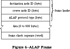 Figure 6–ALAP Frame
Two of the protocol handlers in every node are used by DDP. These protocol handlers service frames with ALAP protocol types equal to the following global constants:
shortDDP .EQU 1 ;short DDP header
longDDP .EQU 2 ;long DDP header
When you call ALAP to send a frame, you pass it information about the frame in a write data structure, which has the format shown in Figure 7.
Figure 6–ALAP Frame
Two of the protocol handlers in every node are used by DDP. These protocol handlers service frames with ALAP protocol types equal to the following global constants:
shortDDP .EQU 1 ;short DDP header
longDDP .EQU 2 ;long DDP header
When you call ALAP to send a frame, you pass it information about the frame in a write data structure, which has the format shown in Figure 7.
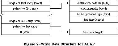 Figure 7–Write Data Structure for ALAP
If you specify a destination node ID of 255, the frame will be broadcast to all nodes. The byte that’s “used internally” is used by the AppleTalk Manager to store the address of the node sending the frame.
»Using ALAP
Most programs will never need to call ALAP, because higher-level protocols will automatically call ALAP as necessary. If you do want to send a frame directly via an ALAP, call the WriteLAP function. There’s no ReadLAP function in assembly language; if you want to read ALAP frames, you must call AttachPH to add your protocol handler to the node’s protocol handler table. The ALAP module will examine every incoming frame and call your protocol handler for each frame received with the correct ALAP protocol. When your program no longer wants to receive frames with a particular ALAP protocol type value, it can call DetachPH to remove the corresponding protocol handler from the protocol handler table.
See the “Protocol Handlers and Socket Listeners” section for information on how to write a protocol handler.
»ALAP Routines
WriteLAP function
Parameter block
--> 26 csCode word ;always writeLAP
--> 30 wdsPointer pointer ;write data structure
WriteLAP sends a frame to another node. The frame data and destination of the frame are described by the write data structure pointed to by wdsPointer. The first two data bytes of an ALAP frame sent to another computer using the AppleTalk Manager must indicate the length of the frame in bytes. The ALAP protocol type byte must be in the range 1 to 127.
Result codes noErr No error
excessCollsns No CTS received after 32 RTS’s
ddpLengthErr Packet length exceeds maximum
lapProtErr Invalid ALAP protocol type
AttachPH function
Parameter block
--> 26 csCode word ;always attachPH
--> 28 protType byte ;ALAP protocol type
--> 30 handler pointer ;protocol handler
AttachPH adds the protocol handler pointed to by handler to the node’s protocol table. ProtType specifies what kind of frame the protocol handler can service. After AttachPH is called, the protocol handler is called for each incoming frame whose ALAP protocol type equals protType.
Result codes noErr No error
lapProtErr Error attaching protocol type
DetachPH function
Parameter block
--> 26 csCode word ;always detachPH
--> 28 protType byte ;ALAP protocol type
DetachPH removes from the node’s protocol table the specified ALAP protocol type and corresponding protocol handler.
Result codes noErr No error
lapProtErr Error detaching protocol type
_______________________________________________________________________________
»Datagram Delivery Protocol
»Data Structures
A DDP datagram consists of a header followed by up to 586 bytes of actual data
(Figure 8). The headers can be of two different lengths; they’re identified by the following ALAP protocol types:
shortDDP .EQU 1 ;short DDP header
longDDP .EQU 2 ;long DDP header
Figure 7–Write Data Structure for ALAP
If you specify a destination node ID of 255, the frame will be broadcast to all nodes. The byte that’s “used internally” is used by the AppleTalk Manager to store the address of the node sending the frame.
»Using ALAP
Most programs will never need to call ALAP, because higher-level protocols will automatically call ALAP as necessary. If you do want to send a frame directly via an ALAP, call the WriteLAP function. There’s no ReadLAP function in assembly language; if you want to read ALAP frames, you must call AttachPH to add your protocol handler to the node’s protocol handler table. The ALAP module will examine every incoming frame and call your protocol handler for each frame received with the correct ALAP protocol. When your program no longer wants to receive frames with a particular ALAP protocol type value, it can call DetachPH to remove the corresponding protocol handler from the protocol handler table.
See the “Protocol Handlers and Socket Listeners” section for information on how to write a protocol handler.
»ALAP Routines
WriteLAP function
Parameter block
--> 26 csCode word ;always writeLAP
--> 30 wdsPointer pointer ;write data structure
WriteLAP sends a frame to another node. The frame data and destination of the frame are described by the write data structure pointed to by wdsPointer. The first two data bytes of an ALAP frame sent to another computer using the AppleTalk Manager must indicate the length of the frame in bytes. The ALAP protocol type byte must be in the range 1 to 127.
Result codes noErr No error
excessCollsns No CTS received after 32 RTS’s
ddpLengthErr Packet length exceeds maximum
lapProtErr Invalid ALAP protocol type
AttachPH function
Parameter block
--> 26 csCode word ;always attachPH
--> 28 protType byte ;ALAP protocol type
--> 30 handler pointer ;protocol handler
AttachPH adds the protocol handler pointed to by handler to the node’s protocol table. ProtType specifies what kind of frame the protocol handler can service. After AttachPH is called, the protocol handler is called for each incoming frame whose ALAP protocol type equals protType.
Result codes noErr No error
lapProtErr Error attaching protocol type
DetachPH function
Parameter block
--> 26 csCode word ;always detachPH
--> 28 protType byte ;ALAP protocol type
DetachPH removes from the node’s protocol table the specified ALAP protocol type and corresponding protocol handler.
Result codes noErr No error
lapProtErr Error detaching protocol type
_______________________________________________________________________________
»Datagram Delivery Protocol
»Data Structures
A DDP datagram consists of a header followed by up to 586 bytes of actual data
(Figure 8). The headers can be of two different lengths; they’re identified by the following ALAP protocol types:
shortDDP .EQU 1 ;short DDP header
longDDP .EQU 2 ;long DDP header
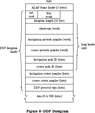 Figure 8–DDP Datagram
Long DDP headers (13 bytes) are used for sending datagrams between two or more different AppleTalk networks. You can use the following global constants to access the contents of a long DDP header:
ddpHopCnt .EQU 0 ;count of bridges passed (4 bits)
ddpLength .EQU 0 ;datagram length (10 bits)
ddpChecksum .EQU 2 ;checksum
ddpDstNet .EQU 4 ;destination network number
ddpSrcNet .EQU 6 ;source network number
ddpDstNode .EQU 8 ;destination node ID
ddpSrcNode .EQU 9 ;source node ID
ddpDstSkt .EQU 10 ;destination socket number
ddpSrcSkt .EQU 11 ;source socket number
ddpType .EQU 12 ;DDP protocol type
The size of a DDP long header is given by the following constant:
ddpHSzLong .EQU ddpType+1
The short headers (five bytes) are used for datagrams sent to sockets within the same network as the source socket. You can use the following global constants to access the contents of a short DDP header:
ddpLength .EQU 0 ;datagram length
sDDPDstSkt .EQU ddpChecksum ;destination socket number
sDDPSrcSkt .EQU sDDPDstSkt+1 ;source socket number
sDDPType .EQU sDDPSrcSkt+1 ;DDP protocol type
The size of a DDP short header is given by the following constant:
ddpHSzShort .EQU sDDPType+1
The datagram length is a ten-bit field. You can use the following global constant as a mask for these bits:
ddpLenMask .EQU $03FF
The following constant indicates the maximum length of a DDP datagram:
ddpMaxData .EQU 586
When you call DDP to send a datagram, you pass it information about the datagram in a write data structure with the format shown in Figure 9.
Figure 8–DDP Datagram
Long DDP headers (13 bytes) are used for sending datagrams between two or more different AppleTalk networks. You can use the following global constants to access the contents of a long DDP header:
ddpHopCnt .EQU 0 ;count of bridges passed (4 bits)
ddpLength .EQU 0 ;datagram length (10 bits)
ddpChecksum .EQU 2 ;checksum
ddpDstNet .EQU 4 ;destination network number
ddpSrcNet .EQU 6 ;source network number
ddpDstNode .EQU 8 ;destination node ID
ddpSrcNode .EQU 9 ;source node ID
ddpDstSkt .EQU 10 ;destination socket number
ddpSrcSkt .EQU 11 ;source socket number
ddpType .EQU 12 ;DDP protocol type
The size of a DDP long header is given by the following constant:
ddpHSzLong .EQU ddpType+1
The short headers (five bytes) are used for datagrams sent to sockets within the same network as the source socket. You can use the following global constants to access the contents of a short DDP header:
ddpLength .EQU 0 ;datagram length
sDDPDstSkt .EQU ddpChecksum ;destination socket number
sDDPSrcSkt .EQU sDDPDstSkt+1 ;source socket number
sDDPType .EQU sDDPSrcSkt+1 ;DDP protocol type
The size of a DDP short header is given by the following constant:
ddpHSzShort .EQU sDDPType+1
The datagram length is a ten-bit field. You can use the following global constant as a mask for these bits:
ddpLenMask .EQU $03FF
The following constant indicates the maximum length of a DDP datagram:
ddpMaxData .EQU 586
When you call DDP to send a datagram, you pass it information about the datagram in a write data structure with the format shown in Figure 9.
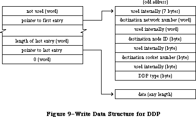 Figure 9–Write Data Structure for DDP
The first seven bytes are used internally for the ALAP header and the DDP datagram length and checksum. The other bytes used internally store the network number, node ID, and socket number of the socket client sending the datagram.
Warning: The first entry in a DDP write data structure must begin at
an odd address.
If you specify a node ID of 255, the datagram will be broadcast to all nodes within the destination network. A network number of 0 means the local network to which the node is connected.
Warning: DDP always destroys the high-order byte of the destination
network number when it sends a datagram with a short header.
Therefore, if you want to reuse the first entry of a DDP write
data structure entry, you must restore the destination network number.
»Using DDP
Before it can use a socket, the program must call OpenSkt, which adds a socket and its socket listener to the socket table. When a client is finished using a socket, call CloseSkt, which removes the socket’s entry from the socket table. To send a datagram via DDP, call WriteDDP. If you want to read DDP datagrams, you must write your own socket listener. DDP will send every incoming datagram for that socket to your socket listener.
See the “Protocol Handlers and Socket Listeners” section for information on how to write a socket listener.
»DDP Routines
OpenSkt function
Parameter block
--> 26 csCode word ;always openSkt
<-> 28 socket byte ;socket number
--> 30 listener pointer ;socket listener
OpenSkt adds a socket and its socket listener to the socket table. If the socket parameter is nonzero, it must be in the range 64 to 127, and it specifies the socket’s number; if socket is 0, OpenSkt opens a socket with a socket number in the range 128 to 254, and returns it in the socket parameter. Listener contains a pointer to the socket listener.
OpenSkt will return ddpSktErr if you pass the number of an already opened socket, if you pass a socket number greater than 127, or if the socket table is full (the socket table can hold a maximum of 12 sockets).
Result codes noErr No error
ddpSktErr Socket error
CloseSkt function
Parameter block
--> 26 csCode word ;always closeSkt
--> 28 socket byte ;socket number
CloseSkt removes the entry of the specified socket from the socket table. If you pass a socket number of 0, or if you attempt to close a socket that isn’t open, CloseSkt will return ddpSktErr.
Result codes noErr No error
ddpSktErr Socket error
WriteDDP function
Parameter block
--> 26 csCode word ;always writeDDP
--> 28 socket byte ;socket number
--> 29 checksumFlag byte ;checksum flag
--> 30 wdsPointer pointer ;write data structure
WriteDDP sends a datagram to another socket. WDSPointer points to a write data structure containing the datagram and the address of the destination socket. If checksumFlag is TRUE, WriteDDP will compute the checksum for all datagrams requiring long headers.
Result codes noErr No error
ddpLenErr Datagram length too big
ddpSktErr Socket error
noBridgeErr No bridge found
_______________________________________________________________________________
»AppleTalk Transaction Protocol
»Data Structures
An ATP packet consists of an ALAP header, DDP header, and ATP header, followed by actual data (Figure 10). You can use the following global constants to access the contents of an ATP header:
atpControl .EQU 0 ;control information
atpBitMap .EQU 1 ;bit map
atpRespNo .EQU 1 ;sequence number
atpTransID .EQU 2 ;transaction ID
atpUserData .EQU 4 ;user bytes
The size of an ATP header is given by the following constant:
atpHdSz .EQU 8
Figure 9–Write Data Structure for DDP
The first seven bytes are used internally for the ALAP header and the DDP datagram length and checksum. The other bytes used internally store the network number, node ID, and socket number of the socket client sending the datagram.
Warning: The first entry in a DDP write data structure must begin at
an odd address.
If you specify a node ID of 255, the datagram will be broadcast to all nodes within the destination network. A network number of 0 means the local network to which the node is connected.
Warning: DDP always destroys the high-order byte of the destination
network number when it sends a datagram with a short header.
Therefore, if you want to reuse the first entry of a DDP write
data structure entry, you must restore the destination network number.
»Using DDP
Before it can use a socket, the program must call OpenSkt, which adds a socket and its socket listener to the socket table. When a client is finished using a socket, call CloseSkt, which removes the socket’s entry from the socket table. To send a datagram via DDP, call WriteDDP. If you want to read DDP datagrams, you must write your own socket listener. DDP will send every incoming datagram for that socket to your socket listener.
See the “Protocol Handlers and Socket Listeners” section for information on how to write a socket listener.
»DDP Routines
OpenSkt function
Parameter block
--> 26 csCode word ;always openSkt
<-> 28 socket byte ;socket number
--> 30 listener pointer ;socket listener
OpenSkt adds a socket and its socket listener to the socket table. If the socket parameter is nonzero, it must be in the range 64 to 127, and it specifies the socket’s number; if socket is 0, OpenSkt opens a socket with a socket number in the range 128 to 254, and returns it in the socket parameter. Listener contains a pointer to the socket listener.
OpenSkt will return ddpSktErr if you pass the number of an already opened socket, if you pass a socket number greater than 127, or if the socket table is full (the socket table can hold a maximum of 12 sockets).
Result codes noErr No error
ddpSktErr Socket error
CloseSkt function
Parameter block
--> 26 csCode word ;always closeSkt
--> 28 socket byte ;socket number
CloseSkt removes the entry of the specified socket from the socket table. If you pass a socket number of 0, or if you attempt to close a socket that isn’t open, CloseSkt will return ddpSktErr.
Result codes noErr No error
ddpSktErr Socket error
WriteDDP function
Parameter block
--> 26 csCode word ;always writeDDP
--> 28 socket byte ;socket number
--> 29 checksumFlag byte ;checksum flag
--> 30 wdsPointer pointer ;write data structure
WriteDDP sends a datagram to another socket. WDSPointer points to a write data structure containing the datagram and the address of the destination socket. If checksumFlag is TRUE, WriteDDP will compute the checksum for all datagrams requiring long headers.
Result codes noErr No error
ddpLenErr Datagram length too big
ddpSktErr Socket error
noBridgeErr No bridge found
_______________________________________________________________________________
»AppleTalk Transaction Protocol
»Data Structures
An ATP packet consists of an ALAP header, DDP header, and ATP header, followed by actual data (Figure 10). You can use the following global constants to access the contents of an ATP header:
atpControl .EQU 0 ;control information
atpBitMap .EQU 1 ;bit map
atpRespNo .EQU 1 ;sequence number
atpTransID .EQU 2 ;transaction ID
atpUserData .EQU 4 ;user bytes
The size of an ATP header is given by the following constant:
atpHdSz .EQU 8
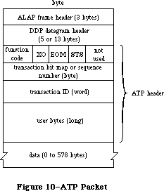 Figure 10–ATP Packet
ATP packets are identified by the following DDP protocol type:
atp .EQU 3
The control information contains a function code and various control bits. The function code identifies either a TReq, TResp, or TRel packet with one of the following global constants:
atpReqCode .EQU $40 ;TReq packet
atpRspCode .EQU $80 ;TResp packet
atpRelCode .EQU $C0 ;TRel packet
The send-transmission-status, end-of-message, and exactly-once bits in the control information are accessed via the following global constants:
atpSTSBit .EQU 3 ;send-transmission-status bit
atpEOMBit .EQU 4 ;end-of-message bit
atpXOBit .EQU 5 ;exactly-once bit
Many ATP calls require a field called atpFlags (Figure 11), which contains the above three bits plus the following two bits:
sendChk .EQU 0 ;send-checksum bit
tidValid .EQU 1 ;transaction ID validity bit
Figure 10–ATP Packet
ATP packets are identified by the following DDP protocol type:
atp .EQU 3
The control information contains a function code and various control bits. The function code identifies either a TReq, TResp, or TRel packet with one of the following global constants:
atpReqCode .EQU $40 ;TReq packet
atpRspCode .EQU $80 ;TResp packet
atpRelCode .EQU $C0 ;TRel packet
The send-transmission-status, end-of-message, and exactly-once bits in the control information are accessed via the following global constants:
atpSTSBit .EQU 3 ;send-transmission-status bit
atpEOMBit .EQU 4 ;end-of-message bit
atpXOBit .EQU 5 ;exactly-once bit
Many ATP calls require a field called atpFlags (Figure 11), which contains the above three bits plus the following two bits:
sendChk .EQU 0 ;send-checksum bit
tidValid .EQU 1 ;transaction ID validity bit
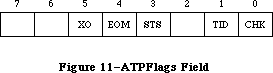 Figure 11–ATPFlags Field
The maximum number of response packets in an ATP transaction is given by the following global constant:
atpMaxNum .EQU 8
When you call ATP to send responses, you pass the responses in a response BDS, which is a list of up to eight elements, each of which contains the following:
bdsBuffSz .EQU 0 ;size of data to send
bdsBuffAddr .EQU 2 ;pointer to data
bdsUserData .EQU 8 ;user bytes
When you call ATP to receive responses, you pass it a response BDS with up to eight elements, each in the following format:
bdsBuffSz .EQU 0 ;buffer size in bytes
bdsBuffAddr .EQU 2 ;pointer to buffer
bdsDataSz .EQU 6 ;number of bytes actually received
bdsUserData .EQU 8 ;user bytes
The size of a BDS element is given by the following constant:
bdsEntrySz .EQU 12
ATP clients are identified by internet addresses in the form shown in Figure 12.
Figure 11–ATPFlags Field
The maximum number of response packets in an ATP transaction is given by the following global constant:
atpMaxNum .EQU 8
When you call ATP to send responses, you pass the responses in a response BDS, which is a list of up to eight elements, each of which contains the following:
bdsBuffSz .EQU 0 ;size of data to send
bdsBuffAddr .EQU 2 ;pointer to data
bdsUserData .EQU 8 ;user bytes
When you call ATP to receive responses, you pass it a response BDS with up to eight elements, each in the following format:
bdsBuffSz .EQU 0 ;buffer size in bytes
bdsBuffAddr .EQU 2 ;pointer to buffer
bdsDataSz .EQU 6 ;number of bytes actually received
bdsUserData .EQU 8 ;user bytes
The size of a BDS element is given by the following constant:
bdsEntrySz .EQU 12
ATP clients are identified by internet addresses in the form shown in Figure 12.
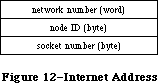 Figure 12–Internet Address
»Using ATP
Before you can use ATP on a Macintosh 128K, the .ATP driver must be read from the system resource file via a Device Manager Open call. The name of the .ATP driver is '.ATP' and its reference number is –11. When the .ATP driver is opened, it reads its ATP code into the application heap and installs a task into the vertical retrace queue.
Warning: When another application starts up, the application heap is
reinitialized; on a Macintosh 128K, this means that the ATP
code is lost (and must be reloaded by the next application).
When you’re through using ATP on a Macintosh 128K, call the Device Manager Close routine—the system will be returned to the state it was in before the
.ATP driver was opened.
On a Macintosh 512K or XL, the .ATP driver will have been loaded into the system heap either at system startup or upon execution of a Device Manager Open call loading MPP. You shouldn’t close the .ATP driver on a Macintosh 512K or XL; AppleTalk expects it to remain open on these systems.
To send a request to another socket and get a response, call SendRequest. The call terminates when either an entire response is received or a specified retry timeout interval elapses. To open a socket for the purpose of responding to requests, call OpenATPSkt. Then call GetRequest to receive a request; when a request is received, the call is completed. After receiving and servicing a request, call SendResponse to return response information. If you cannot or do not want to send the entire response all at once, make a SendResponse call to send some of the response, and then call AddResponse later to send the remainder of the response. To close a socket opened for the purpose of sending responses, call CloseATPSkt.
During exactly-once transactions, SendResponse doesn’t terminate until the transaction is completed via a TRel packet, or the retry count is exceeded.
Warning: Don’t modify the parameter block passed to an ATP call until
the call is completed.
»ATP Routines
OpenATPSkt function
Parameter block
--> 26 csCode word ;always openATPSkt
<-> 28 atpSocket byte ;socket number
--> 30 addrBlock long word ;socket request specification
OpenATPSkt opens a socket for the purpose of receiving requests. ATPSocket contains the socket number of the socket to open. If it’s 0, a number is dynamically assigned and returned in atpSocket. AddrBlock contains a specification of the socket addresses from which requests will be accepted. A 0 in the network number, node ID, or socket number field of addrBlock means that requests will be accepted from every network, node, or socket, respectively.
Result codes noErr No error
tooManySkts Too many responding sockets
noDataArea Too many outstanding ATP calls
CloseATPSkt function
Parameter block
--> 26 csCode word ;always closeATPSkt
--> 28 atpSocket byte ;socket number
CloseATPSkt closes the socket whose number is specified by atpSocket, for the purpose of receiving requests.
Result codes noErr No error
noDataArea Too many outstanding ATP calls
SendRequest function
Parameter block
--> 18 userData long word ;user bytes
<-- 22 reqTID word ;transaction ID used in request
--> 26 csCode word ;always sendRequest
<-- 28 currBitMap byte ;bit map
<-> 29 atpFlags byte ;control information
--> 30 addrBlock long word ;destination socket address
--> 34 reqLength word ;request size in bytes
--> 36 reqPointer pointer ;pointer to request data
--> 40 bdsPointer pointer ;pointer to response BDS
--> 44 numOfBuffs byte ;number of responses expected
--> 45 timeOutVal byte ;timeout interval
<-- 46 numOfResps byte ;number of responses received
<-> 47 retryCount byte ;number of retries
SendRequest sends a request to another socket and waits for a response. UserData contains the four user bytes. AddrBlock indicates the socket to which the request should be sent. ReqLength and reqPointer contain the size and location of the request to send. BDSPointer points to a response BDS where the responses are to be returned; numOfBuffs indicates the number of responses requested. The number of responses received is returned in numOfResps. If a nonzero value is returned in numOfResps, you can examine currBitMap to determine which packets of the transaction were actually received and to detect pieces for higher-level recovery, if desired.
TimeOutVal indicates the number of seconds that SendRequest should wait for a response before resending the request. RetryCount indicates the maximum number of retries SendRequest should attempt. The end-of-message flag of atpFlags will be set if the EOM bit is set in the last packet received in a valid response sequence. The exactly-once flag should be set if you want the request to be part of an exactly-once transaction.
To cancel a SendRequest call, you need the transaction ID; it’s returned in reqTID. You can examine reqTID before the completion of the call, but its contents are valid only after the tidValid bit of atpFlags has been set.
SendRequest completes when either an entire response is received or the retry count is exceeded.
Note: The value provided in retryCount will be modified during SendRequest
if any retries are made. This field is used to monitor the number of
retries; for each retry, it’s decremented by 1.
Result codes noErr No error
reqFailed Retry count exceeded
tooManyReqs Too many concurrent requests
noDataArea Too many outstanding ATP calls
reqAborted Request canceled by user
GetRequest function
Parameter block
<-- 18 userData long word ;user bytes
--> 26 csCode word ;always getRequest
--> 28 atpSocket byte ;socket number
<-- 29 atpFlags byte ;control information
<-- 30 addrBlock long word ;source of request
<-> 34 reqLength word ;request buffer size
--> 36 reqPointer pointer ;pointer to request buffer
<-- 44 bitMap byte ;bit map
<-- 46 transID word ;transaction ID
GetRequest sets up the mechanism to receive a request sent by a SendRequest call. UserData returns the four user bytes from the request. ATPSocket contains the socket number of the socket that should listen for a request. The internet address of the socket from which the request was sent is returned in addrBlock. ReqLength and reqPointer indicate the size (in bytes) and location of a buffer to store the incoming request. The actual size of the request is returned in reqLength. The transaction bit map and transaction ID will be returned in bitMap and transID. The exactly-once flag in atpFlags will be set if the request is part of an exactly-once transaction.
GetRequest completes when a request is received.
Result codes noErr No error
badATPSkt Bad responding socket
SendResponse function
Parameter block
<-- 18 userData long word ;user bytes from TRel
<-- 22 reqTID word ;transaction ID used in request
--> 26 csCode word ;always sendResponse
--> 28 atpSocket byte ;socket number
--> 29 atpFlags byte ;control information
--> 30 addrBlock long word ;response destination
--> 40 bdsPointer pointer ;pointer to response BDS
--> 44 numOfBuffs byte ;number of response packets being sent
--> 45 bdsSize byte ;BDS size in elements
--> 46 transID word ;transaction ID
SendResponse sends a response to a socket. If the response was part of an exactly-once transaction, userData will contain the user bytes from the TRel packet. ATPSocket contains the socket number from which the response should be sent. The end-of-message flag in atpFlags should be set if the response contains the final packet in a transaction composed of a group of packets and the number of responses is less than requested. AddrBlock indicates the address of the socket to which the response should be sent. BDSPointer points to a response BDS containing room for the maximum number of responses to be sent; bdsSize contains this maximum number. NumOfBuffs contains the number of response packets to be sent in this call; you may wish to make AddResponse calls to complete the response. TransID indicates the transaction ID of the associated request.
During exactly-once transactions, SendResponse doesn’t complete until either a TRel packet is received from the socket that made the request, or the retry count is exceeded.
Result codes noErr No error
badATPSkt Bad responding socket
noRelErr No release received
noDataArea Too many outstanding ATP calls
badBuffNum Sequence number out of range
AddResponse function
Parameter block
--> 18 userData long word ;user bytes
--> 26 csCode word ;always addResponse
--> 28 atpSocket byte ;socket number
--> 29 atpFlags byte ;control information
--> 30 addrBlock long word ;response destination
--> 34 reqLength word ;response size
--> 36 reqPointer pointer ;pointer to response
--> 44 rspNum byte ;sequence number
--> 46 transID word ;transaction ID
AddResponse sends an additional response packet to a socket that has already been sent the initial part of a response via SendResponse. UserData contains the four user bytes. ATPSocket contains the socket number from which the response should be sent. The end-of-message flag in atpFlags should be set if this response packet is the final packet in a transaction composed of a group of packets and the number of responses is less than requested. AddrBlock indicates the socket to which the response should be sent. ReqLength and reqPointer contain the size (in bytes) and location of the response to send; rspNum indicates the sequence number of the response (in the range 0 to 7). TransID must contain the transaction ID.
Warning: If the transaction is part of an exactly-once transaction, the
buffer used in the AddResponse call must not be altered or
released until the corresponding SendResponse call has completed.
Result codes noErr No error
badATPSkt Bad responding socket
noSendResp AddResponse issued before SendResponse
badBuffNum Sequence number out of range
noDataArea Too many outstanding ATP calls
RelTCB function
Parameter block
--> 26 csCode word ;always relTCB
--> 30 addrBlock long word ;destination of request
--> 46 transID word ;transaction ID of request
RelTCB dequeues the specified SendRequest call and returns the result code reqAborted for the aborted call. The transaction ID can be obtained from the reqTID field of the SendRequest queue entry; see the description of SendRequest for details.
Result codes noErr No error
cbNotFound ATP control block not found
noDataArea Too many outstanding ATP calls
RelRspCB function
Parameter block
--> 26 csCode word ;always relRspCB
--> 28 atpSocket byte ;socket number that request was received on
--> 30 addrBlock long word ;source of request
--> 46 transID word ;transaction ID of request
In an exactly-once transaction, RelRspCB cancels the specified SendResponse, without waiting for the release timer to expire or a TRel packet to be received. No error is returned for the SendResponse call. Whan called to cancel a transaction that isn’t using exactly-once service, RelRspCB returns cbNotFound. The transaction ID can be obtained from the reqTID field of the SendResponse queue entry; see the description of SendResponse for details.
Result codes noErr No error
cbNotFound ATP control block not found
_______________________________________________________________________________
»Name-Binding Protocol
»Data Structures
The first two bytes in the NBP header (Figure 13) indicate the type of the packet, the number of tuples in the packet, and an NBP packet identifier. You can use the following global constants to access these bytes:
nbpControl .EQU 0 ;packet type
nbpTCount .EQU 0 ;tuple count
nbpID .EQU 1 ;packet identifier
nbpTuple .EQU 2 ;start of first tuple
Figure 12–Internet Address
»Using ATP
Before you can use ATP on a Macintosh 128K, the .ATP driver must be read from the system resource file via a Device Manager Open call. The name of the .ATP driver is '.ATP' and its reference number is –11. When the .ATP driver is opened, it reads its ATP code into the application heap and installs a task into the vertical retrace queue.
Warning: When another application starts up, the application heap is
reinitialized; on a Macintosh 128K, this means that the ATP
code is lost (and must be reloaded by the next application).
When you’re through using ATP on a Macintosh 128K, call the Device Manager Close routine—the system will be returned to the state it was in before the
.ATP driver was opened.
On a Macintosh 512K or XL, the .ATP driver will have been loaded into the system heap either at system startup or upon execution of a Device Manager Open call loading MPP. You shouldn’t close the .ATP driver on a Macintosh 512K or XL; AppleTalk expects it to remain open on these systems.
To send a request to another socket and get a response, call SendRequest. The call terminates when either an entire response is received or a specified retry timeout interval elapses. To open a socket for the purpose of responding to requests, call OpenATPSkt. Then call GetRequest to receive a request; when a request is received, the call is completed. After receiving and servicing a request, call SendResponse to return response information. If you cannot or do not want to send the entire response all at once, make a SendResponse call to send some of the response, and then call AddResponse later to send the remainder of the response. To close a socket opened for the purpose of sending responses, call CloseATPSkt.
During exactly-once transactions, SendResponse doesn’t terminate until the transaction is completed via a TRel packet, or the retry count is exceeded.
Warning: Don’t modify the parameter block passed to an ATP call until
the call is completed.
»ATP Routines
OpenATPSkt function
Parameter block
--> 26 csCode word ;always openATPSkt
<-> 28 atpSocket byte ;socket number
--> 30 addrBlock long word ;socket request specification
OpenATPSkt opens a socket for the purpose of receiving requests. ATPSocket contains the socket number of the socket to open. If it’s 0, a number is dynamically assigned and returned in atpSocket. AddrBlock contains a specification of the socket addresses from which requests will be accepted. A 0 in the network number, node ID, or socket number field of addrBlock means that requests will be accepted from every network, node, or socket, respectively.
Result codes noErr No error
tooManySkts Too many responding sockets
noDataArea Too many outstanding ATP calls
CloseATPSkt function
Parameter block
--> 26 csCode word ;always closeATPSkt
--> 28 atpSocket byte ;socket number
CloseATPSkt closes the socket whose number is specified by atpSocket, for the purpose of receiving requests.
Result codes noErr No error
noDataArea Too many outstanding ATP calls
SendRequest function
Parameter block
--> 18 userData long word ;user bytes
<-- 22 reqTID word ;transaction ID used in request
--> 26 csCode word ;always sendRequest
<-- 28 currBitMap byte ;bit map
<-> 29 atpFlags byte ;control information
--> 30 addrBlock long word ;destination socket address
--> 34 reqLength word ;request size in bytes
--> 36 reqPointer pointer ;pointer to request data
--> 40 bdsPointer pointer ;pointer to response BDS
--> 44 numOfBuffs byte ;number of responses expected
--> 45 timeOutVal byte ;timeout interval
<-- 46 numOfResps byte ;number of responses received
<-> 47 retryCount byte ;number of retries
SendRequest sends a request to another socket and waits for a response. UserData contains the four user bytes. AddrBlock indicates the socket to which the request should be sent. ReqLength and reqPointer contain the size and location of the request to send. BDSPointer points to a response BDS where the responses are to be returned; numOfBuffs indicates the number of responses requested. The number of responses received is returned in numOfResps. If a nonzero value is returned in numOfResps, you can examine currBitMap to determine which packets of the transaction were actually received and to detect pieces for higher-level recovery, if desired.
TimeOutVal indicates the number of seconds that SendRequest should wait for a response before resending the request. RetryCount indicates the maximum number of retries SendRequest should attempt. The end-of-message flag of atpFlags will be set if the EOM bit is set in the last packet received in a valid response sequence. The exactly-once flag should be set if you want the request to be part of an exactly-once transaction.
To cancel a SendRequest call, you need the transaction ID; it’s returned in reqTID. You can examine reqTID before the completion of the call, but its contents are valid only after the tidValid bit of atpFlags has been set.
SendRequest completes when either an entire response is received or the retry count is exceeded.
Note: The value provided in retryCount will be modified during SendRequest
if any retries are made. This field is used to monitor the number of
retries; for each retry, it’s decremented by 1.
Result codes noErr No error
reqFailed Retry count exceeded
tooManyReqs Too many concurrent requests
noDataArea Too many outstanding ATP calls
reqAborted Request canceled by user
GetRequest function
Parameter block
<-- 18 userData long word ;user bytes
--> 26 csCode word ;always getRequest
--> 28 atpSocket byte ;socket number
<-- 29 atpFlags byte ;control information
<-- 30 addrBlock long word ;source of request
<-> 34 reqLength word ;request buffer size
--> 36 reqPointer pointer ;pointer to request buffer
<-- 44 bitMap byte ;bit map
<-- 46 transID word ;transaction ID
GetRequest sets up the mechanism to receive a request sent by a SendRequest call. UserData returns the four user bytes from the request. ATPSocket contains the socket number of the socket that should listen for a request. The internet address of the socket from which the request was sent is returned in addrBlock. ReqLength and reqPointer indicate the size (in bytes) and location of a buffer to store the incoming request. The actual size of the request is returned in reqLength. The transaction bit map and transaction ID will be returned in bitMap and transID. The exactly-once flag in atpFlags will be set if the request is part of an exactly-once transaction.
GetRequest completes when a request is received.
Result codes noErr No error
badATPSkt Bad responding socket
SendResponse function
Parameter block
<-- 18 userData long word ;user bytes from TRel
<-- 22 reqTID word ;transaction ID used in request
--> 26 csCode word ;always sendResponse
--> 28 atpSocket byte ;socket number
--> 29 atpFlags byte ;control information
--> 30 addrBlock long word ;response destination
--> 40 bdsPointer pointer ;pointer to response BDS
--> 44 numOfBuffs byte ;number of response packets being sent
--> 45 bdsSize byte ;BDS size in elements
--> 46 transID word ;transaction ID
SendResponse sends a response to a socket. If the response was part of an exactly-once transaction, userData will contain the user bytes from the TRel packet. ATPSocket contains the socket number from which the response should be sent. The end-of-message flag in atpFlags should be set if the response contains the final packet in a transaction composed of a group of packets and the number of responses is less than requested. AddrBlock indicates the address of the socket to which the response should be sent. BDSPointer points to a response BDS containing room for the maximum number of responses to be sent; bdsSize contains this maximum number. NumOfBuffs contains the number of response packets to be sent in this call; you may wish to make AddResponse calls to complete the response. TransID indicates the transaction ID of the associated request.
During exactly-once transactions, SendResponse doesn’t complete until either a TRel packet is received from the socket that made the request, or the retry count is exceeded.
Result codes noErr No error
badATPSkt Bad responding socket
noRelErr No release received
noDataArea Too many outstanding ATP calls
badBuffNum Sequence number out of range
AddResponse function
Parameter block
--> 18 userData long word ;user bytes
--> 26 csCode word ;always addResponse
--> 28 atpSocket byte ;socket number
--> 29 atpFlags byte ;control information
--> 30 addrBlock long word ;response destination
--> 34 reqLength word ;response size
--> 36 reqPointer pointer ;pointer to response
--> 44 rspNum byte ;sequence number
--> 46 transID word ;transaction ID
AddResponse sends an additional response packet to a socket that has already been sent the initial part of a response via SendResponse. UserData contains the four user bytes. ATPSocket contains the socket number from which the response should be sent. The end-of-message flag in atpFlags should be set if this response packet is the final packet in a transaction composed of a group of packets and the number of responses is less than requested. AddrBlock indicates the socket to which the response should be sent. ReqLength and reqPointer contain the size (in bytes) and location of the response to send; rspNum indicates the sequence number of the response (in the range 0 to 7). TransID must contain the transaction ID.
Warning: If the transaction is part of an exactly-once transaction, the
buffer used in the AddResponse call must not be altered or
released until the corresponding SendResponse call has completed.
Result codes noErr No error
badATPSkt Bad responding socket
noSendResp AddResponse issued before SendResponse
badBuffNum Sequence number out of range
noDataArea Too many outstanding ATP calls
RelTCB function
Parameter block
--> 26 csCode word ;always relTCB
--> 30 addrBlock long word ;destination of request
--> 46 transID word ;transaction ID of request
RelTCB dequeues the specified SendRequest call and returns the result code reqAborted for the aborted call. The transaction ID can be obtained from the reqTID field of the SendRequest queue entry; see the description of SendRequest for details.
Result codes noErr No error
cbNotFound ATP control block not found
noDataArea Too many outstanding ATP calls
RelRspCB function
Parameter block
--> 26 csCode word ;always relRspCB
--> 28 atpSocket byte ;socket number that request was received on
--> 30 addrBlock long word ;source of request
--> 46 transID word ;transaction ID of request
In an exactly-once transaction, RelRspCB cancels the specified SendResponse, without waiting for the release timer to expire or a TRel packet to be received. No error is returned for the SendResponse call. Whan called to cancel a transaction that isn’t using exactly-once service, RelRspCB returns cbNotFound. The transaction ID can be obtained from the reqTID field of the SendResponse queue entry; see the description of SendResponse for details.
Result codes noErr No error
cbNotFound ATP control block not found
_______________________________________________________________________________
»Name-Binding Protocol
»Data Structures
The first two bytes in the NBP header (Figure 13) indicate the type of the packet, the number of tuples in the packet, and an NBP packet identifier. You can use the following global constants to access these bytes:
nbpControl .EQU 0 ;packet type
nbpTCount .EQU 0 ;tuple count
nbpID .EQU 1 ;packet identifier
nbpTuple .EQU 2 ;start of first tuple
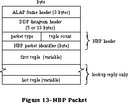 Figure 13–NBP Packet
NBP packets are identified by the following DDP protocol type:
nbp .EQU 2
NBP uses the following global constants in the nbpControl field to identify NBP packets:
brRq .EQU 1 ;broadcast request
lkUp .EQU 2 ;lookup request
lkUpReply .EQU 3 ;lookup reply
NBP entities are identified by internet address in the form shown in Figure 14 below. Entities are also identified by tuples, which include both an internet address and an entity name. You can use the following global constants to access information in tuples:
tupleNet .EQU 0 ;network number
tupleNode .EQU 2 ;node ID
tupleSkt .EQU 3 ;socket number
tupleEnum .EQU 4 ;used internally
tupleName .EQU 5 ;entity name
The meta-characters in an entity name can be identified with the following global constants:
equals .EQU '=' ;“wild-card” meta-character
star .EQU '*' ;“this zone” meta-character
Figure 13–NBP Packet
NBP packets are identified by the following DDP protocol type:
nbp .EQU 2
NBP uses the following global constants in the nbpControl field to identify NBP packets:
brRq .EQU 1 ;broadcast request
lkUp .EQU 2 ;lookup request
lkUpReply .EQU 3 ;lookup reply
NBP entities are identified by internet address in the form shown in Figure 14 below. Entities are also identified by tuples, which include both an internet address and an entity name. You can use the following global constants to access information in tuples:
tupleNet .EQU 0 ;network number
tupleNode .EQU 2 ;node ID
tupleSkt .EQU 3 ;socket number
tupleEnum .EQU 4 ;used internally
tupleName .EQU 5 ;entity name
The meta-characters in an entity name can be identified with the following global constants:
equals .EQU '=' ;“wild-card” meta-character
star .EQU '*' ;“this zone” meta-character
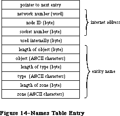 Figure 14–Names Table Entry
The maximum number of tuples in an NBP packet is given by the following global constant:
tupleMax .EQU 15
Entity names are mapped to sockets via the names table. Each entry in the names table has the structure shown in Figure 14.
You can use the following global constants to access some of the elements of a names table entry:
ntLink .EQU 0 ;pointer to next entry
ntTuple .EQU 4 ;tuple
ntSocket .EQU 7 ;socket number
ntEntity .EQU 9 ;entity name
The socket number of the names information socket is given by the following global constant:
nis .EQU 2
»Using NBP
On a Macintosh 128K, before calling any other NBP routines, call the LoadNBP function, which reads the NBP code from the system resource file into the application heap. (The NBP code is part of the .MPP driver, which has a driver reference number of –10.) When you’re finished with NBP and want to reclaim the space its code occupies, call UnloadNBP. On a Macintosh 512K or XL, the NBP code is read in when the .MPP driver is loaded.
Warning: When an application starts up, the application heap is
reinitialized; on a Macintosh 128K, this means that the
NBP code is lost (and must be reloaded by the next application).
When an entity wants to communicate via an AppleTalk network, it should call RegisterName to place its name and internet address in the names table. When an entity no longer wants to communicate on the network, or is being shut down, it should call RemoveName to remove its entry from the names table.
To determine the address of an entity you know only by name, call LookupName, which returns a list of all entities with the name you specify. If you already know the address of an entity, and want only to confirm that it still exists, call ConfirmName. ConfirmName is more efficient than LookupName in terms of network traffic.
»NBP Routines
RegisterName function
Parameter block
--> 26 csCode word ;always registerName
--> 28 interval byte ;retry interval
<-> 29 count byte ;retry count
--> 30 ntQElPtr pointer ;names table element pointer
--> 34 verifyFlag byte ;set if verify needed
RegisterName adds the name and address of an entity to the node’s names table. NTQElPtr points to a names table entry containing the entity’s name and internet address (in the form shown in Figure 14 above). Meta-characters aren’t allowed in the object and type fields of the entity name; the zone field, however, must contain the meta-character “*”. If verifyFlag is TRUE, RegisterName checks on the network to see if the name is already in use, and returns a result code of nbpDuplicate if so. Interval and count contain the retry interval in eight-tick units and the retry count. When a retry is made, the count field is modified.
X-Ref: Technical Note #225
Warning: The names table entry passed to RegisterName remains the
property of NBP until removed from the names table. Don’t
attempt to remove or modify it. If you’ve allocated memory
using a NewHandle call, you must lock it as long as the name
is registered.
Warning: VerifyFlag should normally be set before calling RegisterName.
Result codes noErr No error
nbpDuplicate Duplicate name already exists
nbpNISErr Error opening names information socket
LookupName function
Parameter block
--> 26 csCode word ;always lookupName
--> 28 interval byte ;retry interval
<-> 29 count byte ;retry count
--> 30 entityPtr pointer ;pointer to entity name
--> 34 retBuffPtr pointer ;pointer to buffer
--> 38 retBuffSize word ;buffer size in bytes
--> 40 maxToGet word ;matches to get
<-- 42 numGotten word ;matches found
LookupName returns the addresses of all entities with a specified name. EntityPtr points to the entity’s name (in the form shown in Figure 14 above). Meta-characters are allowed in the entity name. RetBuffPtr and retBuffSize contain the location and size of an area of memory in which the tuples describing the entity names and their corresponding addresses should be returned. MaxToGet indicates the maximum number of matching names to find addresses for; the actual number of addresses found is returned in numGotten. Interval and count contain the retry interval and the retry count. LookupName completes when either the number of matches is equal to or greater than maxToGet, or the retry count has been exceeded. The count field is decremented for each retransmission.
Note: NumGotten is first set to 0 and then incremented with each match
found. You can test the value in this field, and can start examining
the received addresses in the buffer while the lookup continues.
Result codes noErr No error
nbpBuffOvr Buffer overflow
ConfirmName function
Parameter block
--> 26 csCode word ;always confirmName
--> 28 interval byte ;retry interval
<-> 29 count byte ;retry count
--> 30 entityPtr pointer ;pointer to entity name
--> 34 confirmAddr pointer ;entity address
<-- 38 newSocket byte ;socket number
ConfirmName confirms that an entity known by name and address still exists (is still entered in the names directory). EntityPtr points to the entity’s name
(in the form shown in Figure 14 above). ConfirmAddr specifies the address to confirmed. No meta-characters are allowed in the entity name. Interval and count contain the retry interval and the retry count. The socket number of the entity is returned in newSocket. ConfirmName is more efficient than LookupName in terms of network traffic.
Result codes noErr No error
nbpConfDiff Name confirmed for different socket
nbpNoConfirm Name not confirmed
RemoveName function
Parameter block
--> 26 csCode word ;always removeName
--> 30 entityPtr pointer ;pointer to entity name
RemoveName removes an entity name from the names table of the given entity’s node.
Result codes noErr No error
nbpNotFound Name not found
LoadNBP function
Parameter block
--> 26 csCode word ;always loadNBP
On a Macintosh 128K, LoadNBP reads the NBP code from the system resource file into the application heap; on a Macintosh 512K or XL it has no effect.
Result codes noErr No error
UnloadNBP function
Parameter block
--> 26 csCode word ;always unloadNBP
On a Macintosh 128K, UnloadNBP makes the NBP code purgeable; the space isn’t actually released by the Memory Manager until necessary. On a Macintosh 512K or XL, UnloadNBP has no effect.
Result codes noErr No error
_______________________________________________________________________________
»EXTENDED PROTOCOL PACKAGE DRIVER
_______________________________________________________________________________
The Extended Protocol Package (XPP) driver is intended to implement several AppleTalk communication protocols in the same package for ease of use. The
.XPP driver currently consists of two modules that operate on two levels: the low-level module implements the workstation side of AppleTalk Session Protocol, and the high-level module implements a small portion of the workstation side of the AppleTalk Filing Protocol.
This driver adds functionality to the AppleTalk manager by providing services additional to those provided in the .MPP and .ATP drivers. Figure 2 shows the Macintosh AppleTalk drivers and the protocols accessible through each driver.
The .XPP driver maps an AFP call from the client workstation into one or more ASP calls. .XPP provides one client-level call for AFP.
The implementation of AFP in the .XPP driver is very limited. Most calls are a very simple one-to-one mapping from an AFP call to an ASP command without any interpretation of the syntax of the AFP command by the .XPP driver. Refer to the “Mapping AFP Commands” section of this chapter for further information.
_______________________________________________________________________________
»Version
The .XPP driver supports ASP Version (hex) $100, as described in Inside AppleTalk.
_______________________________________________________________________________
»Error Reporting
Errors are returned by the .XPP driver in the ioResult field of the Device Manager Control calls.
The error conditions reported by the .XPP driver may represent the unsuccessful completion of a routine in more than just one process involved in the interaction of the session. System-level, .XPP driver, AppleTalk, and server errors can all turn up in the ioResult field.
AFP calls return codes indicating the unsuccessful completion of AFP commands in the Command Result field of the parameter block (described below).
An application using the .XPP driver should respond appropriately to error conditions reported from the different parts of the interaction. As shown in Figure 3, the following errors can be returned in the ioResult field:
1. System-level errors
System errors returned by the .XPP driver indicate such conditions
as the driver not being open or a specific system call not being
supported. For a complete list of result codes returned by the
Macintosh system software, refer to Appendix A.
2. XPP errors (for example, “Session not opened”)
The .XPP driver can also return errors resulting from its own
activity (for example, the referenced session isn’t open). The
possible .XPP driver errors returned are listed in the .XPP driver
results codes section with each function that can return the code.
3. AppleTalk Errors (returned from lower-level protocols)
.XPP may also return errors from lower-level protocols (for example,
“Socket not open”). Possible error conditions and codes are described
elsewhere in this chapter.
4. An ASP-specific error could be returned from an ASP server in
response to a failed OpenSession call. Errors of this type, returned
by the server to the workstation, are documented both in Inside
AppleTalk, section 11, “AppleTalk Session Protocol”, and in the .XPP
driver results code section of this chapter.
5. The AppleTalk Filing Protocol defines errors that are returned from
the server to the workstation client. These errors are returned in
the cmdResult field of the parameter block (error type 5 in Figure 15).
This field is valid if no system-level error is returned by the call.
Note that at the ASP level, the cmdResult field is client-defined data
and may not be an error code.
Figure 14–Names Table Entry
The maximum number of tuples in an NBP packet is given by the following global constant:
tupleMax .EQU 15
Entity names are mapped to sockets via the names table. Each entry in the names table has the structure shown in Figure 14.
You can use the following global constants to access some of the elements of a names table entry:
ntLink .EQU 0 ;pointer to next entry
ntTuple .EQU 4 ;tuple
ntSocket .EQU 7 ;socket number
ntEntity .EQU 9 ;entity name
The socket number of the names information socket is given by the following global constant:
nis .EQU 2
»Using NBP
On a Macintosh 128K, before calling any other NBP routines, call the LoadNBP function, which reads the NBP code from the system resource file into the application heap. (The NBP code is part of the .MPP driver, which has a driver reference number of –10.) When you’re finished with NBP and want to reclaim the space its code occupies, call UnloadNBP. On a Macintosh 512K or XL, the NBP code is read in when the .MPP driver is loaded.
Warning: When an application starts up, the application heap is
reinitialized; on a Macintosh 128K, this means that the
NBP code is lost (and must be reloaded by the next application).
When an entity wants to communicate via an AppleTalk network, it should call RegisterName to place its name and internet address in the names table. When an entity no longer wants to communicate on the network, or is being shut down, it should call RemoveName to remove its entry from the names table.
To determine the address of an entity you know only by name, call LookupName, which returns a list of all entities with the name you specify. If you already know the address of an entity, and want only to confirm that it still exists, call ConfirmName. ConfirmName is more efficient than LookupName in terms of network traffic.
»NBP Routines
RegisterName function
Parameter block
--> 26 csCode word ;always registerName
--> 28 interval byte ;retry interval
<-> 29 count byte ;retry count
--> 30 ntQElPtr pointer ;names table element pointer
--> 34 verifyFlag byte ;set if verify needed
RegisterName adds the name and address of an entity to the node’s names table. NTQElPtr points to a names table entry containing the entity’s name and internet address (in the form shown in Figure 14 above). Meta-characters aren’t allowed in the object and type fields of the entity name; the zone field, however, must contain the meta-character “*”. If verifyFlag is TRUE, RegisterName checks on the network to see if the name is already in use, and returns a result code of nbpDuplicate if so. Interval and count contain the retry interval in eight-tick units and the retry count. When a retry is made, the count field is modified.
X-Ref: Technical Note #225
Warning: The names table entry passed to RegisterName remains the
property of NBP until removed from the names table. Don’t
attempt to remove or modify it. If you’ve allocated memory
using a NewHandle call, you must lock it as long as the name
is registered.
Warning: VerifyFlag should normally be set before calling RegisterName.
Result codes noErr No error
nbpDuplicate Duplicate name already exists
nbpNISErr Error opening names information socket
LookupName function
Parameter block
--> 26 csCode word ;always lookupName
--> 28 interval byte ;retry interval
<-> 29 count byte ;retry count
--> 30 entityPtr pointer ;pointer to entity name
--> 34 retBuffPtr pointer ;pointer to buffer
--> 38 retBuffSize word ;buffer size in bytes
--> 40 maxToGet word ;matches to get
<-- 42 numGotten word ;matches found
LookupName returns the addresses of all entities with a specified name. EntityPtr points to the entity’s name (in the form shown in Figure 14 above). Meta-characters are allowed in the entity name. RetBuffPtr and retBuffSize contain the location and size of an area of memory in which the tuples describing the entity names and their corresponding addresses should be returned. MaxToGet indicates the maximum number of matching names to find addresses for; the actual number of addresses found is returned in numGotten. Interval and count contain the retry interval and the retry count. LookupName completes when either the number of matches is equal to or greater than maxToGet, or the retry count has been exceeded. The count field is decremented for each retransmission.
Note: NumGotten is first set to 0 and then incremented with each match
found. You can test the value in this field, and can start examining
the received addresses in the buffer while the lookup continues.
Result codes noErr No error
nbpBuffOvr Buffer overflow
ConfirmName function
Parameter block
--> 26 csCode word ;always confirmName
--> 28 interval byte ;retry interval
<-> 29 count byte ;retry count
--> 30 entityPtr pointer ;pointer to entity name
--> 34 confirmAddr pointer ;entity address
<-- 38 newSocket byte ;socket number
ConfirmName confirms that an entity known by name and address still exists (is still entered in the names directory). EntityPtr points to the entity’s name
(in the form shown in Figure 14 above). ConfirmAddr specifies the address to confirmed. No meta-characters are allowed in the entity name. Interval and count contain the retry interval and the retry count. The socket number of the entity is returned in newSocket. ConfirmName is more efficient than LookupName in terms of network traffic.
Result codes noErr No error
nbpConfDiff Name confirmed for different socket
nbpNoConfirm Name not confirmed
RemoveName function
Parameter block
--> 26 csCode word ;always removeName
--> 30 entityPtr pointer ;pointer to entity name
RemoveName removes an entity name from the names table of the given entity’s node.
Result codes noErr No error
nbpNotFound Name not found
LoadNBP function
Parameter block
--> 26 csCode word ;always loadNBP
On a Macintosh 128K, LoadNBP reads the NBP code from the system resource file into the application heap; on a Macintosh 512K or XL it has no effect.
Result codes noErr No error
UnloadNBP function
Parameter block
--> 26 csCode word ;always unloadNBP
On a Macintosh 128K, UnloadNBP makes the NBP code purgeable; the space isn’t actually released by the Memory Manager until necessary. On a Macintosh 512K or XL, UnloadNBP has no effect.
Result codes noErr No error
_______________________________________________________________________________
»EXTENDED PROTOCOL PACKAGE DRIVER
_______________________________________________________________________________
The Extended Protocol Package (XPP) driver is intended to implement several AppleTalk communication protocols in the same package for ease of use. The
.XPP driver currently consists of two modules that operate on two levels: the low-level module implements the workstation side of AppleTalk Session Protocol, and the high-level module implements a small portion of the workstation side of the AppleTalk Filing Protocol.
This driver adds functionality to the AppleTalk manager by providing services additional to those provided in the .MPP and .ATP drivers. Figure 2 shows the Macintosh AppleTalk drivers and the protocols accessible through each driver.
The .XPP driver maps an AFP call from the client workstation into one or more ASP calls. .XPP provides one client-level call for AFP.
The implementation of AFP in the .XPP driver is very limited. Most calls are a very simple one-to-one mapping from an AFP call to an ASP command without any interpretation of the syntax of the AFP command by the .XPP driver. Refer to the “Mapping AFP Commands” section of this chapter for further information.
_______________________________________________________________________________
»Version
The .XPP driver supports ASP Version (hex) $100, as described in Inside AppleTalk.
_______________________________________________________________________________
»Error Reporting
Errors are returned by the .XPP driver in the ioResult field of the Device Manager Control calls.
The error conditions reported by the .XPP driver may represent the unsuccessful completion of a routine in more than just one process involved in the interaction of the session. System-level, .XPP driver, AppleTalk, and server errors can all turn up in the ioResult field.
AFP calls return codes indicating the unsuccessful completion of AFP commands in the Command Result field of the parameter block (described below).
An application using the .XPP driver should respond appropriately to error conditions reported from the different parts of the interaction. As shown in Figure 3, the following errors can be returned in the ioResult field:
1. System-level errors
System errors returned by the .XPP driver indicate such conditions
as the driver not being open or a specific system call not being
supported. For a complete list of result codes returned by the
Macintosh system software, refer to Appendix A.
2. XPP errors (for example, “Session not opened”)
The .XPP driver can also return errors resulting from its own
activity (for example, the referenced session isn’t open). The
possible .XPP driver errors returned are listed in the .XPP driver
results codes section with each function that can return the code.
3. AppleTalk Errors (returned from lower-level protocols)
.XPP may also return errors from lower-level protocols (for example,
“Socket not open”). Possible error conditions and codes are described
elsewhere in this chapter.
4. An ASP-specific error could be returned from an ASP server in
response to a failed OpenSession call. Errors of this type, returned
by the server to the workstation, are documented both in Inside
AppleTalk, section 11, “AppleTalk Session Protocol”, and in the .XPP
driver results code section of this chapter.
5. The AppleTalk Filing Protocol defines errors that are returned from
the server to the workstation client. These errors are returned in
the cmdResult field of the parameter block (error type 5 in Figure 15).
This field is valid if no system-level error is returned by the call.
Note that at the ASP level, the cmdResult field is client-defined data
and may not be an error code.
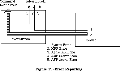 Figure 15–Error Reporting
_______________________________________________________________________________
».XPP Driver Functions Overview
The paragraphs below describe the implementation of ASP in the .XPP driver. For more detailed information about ASP, refer to Inside AppleTalk, Section 11, “AppleTalk Session Protocol (ASP)”.
»Using AppleTalk Name Binding Protocol
A server wishing to advertise its service on the AppleTalk network calls ATP to open an ATP responding socket known as the session listening socket (SLS). The server then calls the Name Binding Protocol (NBP) to register a name on this socket. At this point, the server calls the server side of ASP to pass it the address of the SLS. Then, the server starts listening on the SLS for session opening requests coming over the network.
»Opening and Closing Sessions
When a workstation wishes to access a server, the workstation must call NBP to discover the SLS for that server. Then the workstation calls ASP to open a session with that server.
After determining the SLS (address) of the server, the workstation client issues an OpenSession (or AFPLogin) call to open a session with that server. As a result of this call, ASP sends a special OpenSession packet (an ATP request) to the SLS; this packet carries the address of a workstation socket for use in the session. This socket is referred to as the workstation session socket (WSS). If the server is unable to set up the session, it returns an error. If the request is successful, the server returns no error, and the session is opened. The open session packet also contains a version number so that both ends can verify that they are speaking the same version of ASP.
The AbortOS function can be used to abort an outstanding OpenSession request before it has completed.
The workstation client closes the session by issuing a CloseSession (or AFPLogout). The CloseSession call aborts any calls that are active on the session and closes the session. The session can also be closed by the server or by ASP itself, such as when one end of the session fails. The CloseAll call (which should be used with care) aborts every session that the driver has active.
»Session Maintenance
A session will remain open until it is explicitly terminated by the ASP client at either end or until one of the sessions ends, fails, or becomes unreachable.
»Commands on an Open Session
Once a session has been opened, the workstation client can send a sequence of commands over the session to the server end. The commands are delivered in the same order as they are issued at the workstation end, and replies to the commands are returned to the workstation end.
Three types of commands can be made on an open session. These commands are UserCommand, UserWrite, and AFPCall functions described in the following paragraphs.
UserCommand calls are similar to ATP requests. The workstation client sends a command (included in a variable size command block) to the server client requesting it to perform a particular function and send back a variable size command reply. Examples of such commands vary from a request to open a particular file on a file server, to reading a certain range of bytes from a device. In the first case, a small amount of reply data is returned; in the second case a multiple-packet reply might be generated.
The .XPP driver does not interpret the command block or in any way participate in executing the command’s function. It simply conveys the command block, included in a higher-level format, to the server end of the session, and returns the command reply to the workstation-end client. The command reply consists of a four-byte command result and a variable size command reply block.
UserWrite allows the workstation to convey blocks of data to the server. UserWrite is used to transfer a variable size block of data to the server end of the session and to receive a reply.
The AFPCall function provides a mechanism for passing an AFP command to the server end of an open session and receiving a reply. The first byte of the AFPCall command buffer contains the code for the AFP command that is to be passed to the server for execution. Most AFP calls are implemented through a very simple one-to-one mapping that takes the call and makes an ASP command out of it.
The AFPCall function can have one of four different, but very similar, formats.
»Getting Server Status Information
ASP provides a service to allow its workstation clients to obtain a block of service status information from a server without the need for opening a session. The GetStatus function returns a status block from the server identified by the indicated address. ASP does not impose any structure on the status block. This structure is defined by the protocol above ASP.
»Attention Mechanism
Attentions are defined in ASP as a way for the server to alert the workstation of some event or critical piece of information. The ASP OpenSession and AFPLogin calls include a pointer to an attention routine in their parameter blocks. This attention routine is called by the .XPP driver when it receives an attention from the server and also when the session is closing as described below.
In addition, upon receiving an OpenSession call or AFPLogin call, the .XPP driver sets the first two bytes of the session control block (SCB) to zero. When the .XPP driver receives an attention, the first two bytes of the SCB are set to the attention bytes from the packet (which are always nonzero).
Note: A higher-level language such as Pascal may not wish to have a low-level
attention routine called. A Pascal program can poll the attention bytes,
and if they are ever nonzero, the program will know that an attention
has come in. (It would then set the attention bytes back to zero.)
Of course, two or more attentions could be received between successive
polls, and only the last one would be recorded.
The .XPP driver also calls the attention routine when the session is closed by either the server, workstation, or ASP itself (if the ASP session times out). In these cases, the attention bytes in the SCB are unchanged.
»The Attention Routine
The attention routine is called at interrupt level and must observe interrupt conventions. Specifically, the interrupt routine can change registers A0 through A3 and D0 through D3 and it must not make any Memory Manager calls.
It will be called with
• D0 (word) equal to the SessRefnum for that session (see OpenSession
Function)
• D1 (word) equal to the attention bytes passed by the server (or zero
if the session is closing)
Return with an RTS (return from subroutine) to resume normal execution.
The next section describes the calls that can be made to the .XPP driver.
_______________________________________________________________________________
»CALLING THE .XPP DRIVER
_______________________________________________________________________________
This section describes how to use the .XPP driver and how to call the .XPP driver routines from assembly language and Pascal.
_______________________________________________________________________________
»Using XPP
The .XPP driver implements the workstation side of ASP and provides a mechanism for the workstation to send AppleTalk Filing Protocol (AFP) commands to the server.
»Allocating Memory
Every call to the .XPP driver requires the caller to pass in whatever memory is needed by the driver for the call, generally at the end of the queue element. When a session is opened, the memory required for maintenance of that session
(that is, the Session Control Block) is also passed in.
For standard Device Manager calls, a queue element of a specific size equal to IOQElSize is allocated. When issuing many calls to XPP, it is the caller’s responsibility to allocate a queue element that is large enough to accommodate the .XPP driver’s requirements for executing that call, as defined below. Once allocated, that memory can’t be modified until the call completes.
»Opening the .XPP Driver
To open the .XPP driver, issue a Device Manager Open call. (Refer to the Device Manager chapter.) The name of the .XPP driver is '.XPP'. The original Macintosh ROMs require that .XPP be opened only once. With new ROMs, the .XPP unit number can always be obtained through an Open call. With old ROMs only, the .XPP unit number must be hard coded to XPPUnitNum (40) since only one Open call can be issued to the driver.
The .XPP driver cannot be opened unless AppleTalk is open. The application must ensure that the .MPP and .ATP drivers are opened, as described earlier in this chapter.
The xppLoaded bit (bit 5) in the PortBUse byte in low memory indicates whether or not the .XPP driver is open.
»Example
The following is an example of the procedure an application might use to open the .XPP driver.
; Routine: OpenXPP
;
; Open the .XPP driver and return the driver refNum for it.
;
; Exit: D0 = error code (ccr's set)
; D1 = XPP driver refNum (if no errors)
;
; All other registers preserved
;
xppUnitNum EQU 40 ;default XPP driver number
xppTfRNum EQU -(xppUnitNum+1) ;default XPP driver refNum
OpenXPP
MOVE.L A0-A1/D2,-(SP) ;save registers
MOVE ROM85,D0 ;check ROM type byte
BPL.S @10 ;branch if >=128K ROMs
BTST #xppLoadedBit,PortBUse ;is the XPP driver open already?
BEQ.S @10 ;if not open, then branch to Open code
MOVE #xppTfRNum,D1 ;else use this as driver refnum
MOVEQ #0,D0 ;set noErr
BRA.S @90 ;and exit
;
; XPP driver not open. Make an _Open call to it. If using a 128K
; ROM machine and the driver is already open, we will make another
; Open call to it just so we get the correct driver refNum.
;
@10 SUB #ioQElSize,SP ;allocate temporary param block
MOVE.L SP,A0 ;A0 -> param block
LEA XPPName, A1 ;A1 -> XPP (ASP/AFP) driver name
MOVE.L A1,ioFileName(A0) ;driver name into param block
CLR.B ioPermssn(A0) ;clear permissions byte
_Open
MOVE ioRefNum(A0),D1 ;D1=driver refNum (invalid if error)
ADD #ioQElSize,SP ;deallocate temp param block
@90 MOVE.L (SP)+,A0-A1/D2 ;restore registers
TST D0 ;error? (set ccr's)
RTS
XPPName DC.B 4 ;length of string
DC.B '.XPP' ;driver name
From Pascal, XPP can be opened through the OpenXPP call, which returns the driver’s reference number:
FUNCTION OpenXPP (VAR xppRefnum: INTEGER) : OSErr;
»Open Errors
Errors returned when calling the Device Manager Open routine if the function does not execute properly include the following:
• errors returned by System
• portInUse is returned if the AppleTalk port is in use by a driver
other than AppleTalk or if AppleTalk is not open.
»Closing the .XPP Driver
To close the .XPP driver, call the Device Manager Close routine.
Warning: There is generally no reason to close the driver. Use this
call sparingly, if at all. This call should generally be used
only by system-level applications.
»Close Errors
Errors returned when calling the Device Manager Close routine if the function does not execute properly include the following:
• errors returned by System
• closeErr (new ROMs only) is returned if you try to close the driver
and there are sessions active through that driver. When sessions are
active, closeErr is returned and the driver remains open.
• on old ROMs the driver is closed whether or not sessions are active
and no error is returned. Results are unpredictable if sessions are
still active.
»Session Control Block
The session control block (SCB) is a nonrelocatable block of data passed by the caller to XPP upon session opening. XPP reserves this block for use in maintaining an open session. The SCB size is defined by the constant scbMemSize. The SCB is a locked block, and as long as the session is open, the SCB cannot be modified in any way by the application. There is one SCB for each open session. This block can be reused once a CloseSess call is issued and completed for that session or when the session is indicated as closed.
_______________________________________________________________________________
»How to Access the .XPP Driver
This section contains information for programmers using Pascal and assembly-language routines.
All .XPP driver routines can be executed either synchronously (meaning that the application can’t continue until the routine is completed) or asynchronously
(meaning that the application is free to perform other tasks while the routine is executing).
XPP calls are made from Pascal in the same manner as MPP and ATP calls, with the exception that when making XPP calls the caller must set the XPP driver’s refnum. This refnum is returned in the XPPOpen call’s parameter block.
A Pascal variant record has been defined for all XPP calls. This parameter block is detailed in the “.XPP Driver Parameter Block Record” section below. The first four fields (which are the same for all calls) are automatically filled in by the device manager. The csCode field is automatically filled in by Pascal, depending on which call is being made. The caller must, however, set the ioRefnum field to XPP’s reference number, as returned in the OpenXPP call. The ioVRefnum field is unused.
Note that the parameter block is defined so as to be the maximum size used by any call. Different calls take different size parameter blocks, each call requiring a certain minimum size. Callers are free to abbreviate the parameter block where appropriate.
»General
With each routine, a list of the parameter block fields used by the call is also given. All routines are invoked by Device Manager Control calls with the csCode field equal to the code corresponding to the function being called. The number next to each field name indicates the byte offset of the field from the start of the parameter block pointed to by A0; only assembly-language programmers need to be concerned with it. An arrow next to each parameter name indicates whether it’s an input, output, or input/output parameter:
Arrow Meaning
<-- Parameter is passed
<-- Parameter is returned
<-> Parameter is passed and returned
All Device Manager Control calls return an integer result code in the ioResult field. Each routine description lists all the applicable result codes, along with a short description of what the result code means. Refer to the section
“XPP Driver Result Codes” for an alphabetical list of result codes returned by the .XPP driver.
Each routine description includes a Pascal form of the call. Pascal calls to the .XPP Driver are of the form:
FUNCTION XPPCall (paramBlock: XPPParmBlkPtr,async: BOOLEAN) : OSErr;
XPPCall is the name of the routine.
The parameter paramBlock points to the actual I/O queue element used in the
_Control call, filled in by the caller with the parameters of the routine.
The parameter async indicates whether or not the call should be made asynchronously. If async is TRUE, the call is executed asynchronously; otherwise the call is executed synchronously.
The routine returns a result code of type OSErr.
».XPP Driver Parameter Block Record
XPPParamBlock = PACKED RECORD
qLink: QElemPtr; {next queue entry}
qType: INTEGER; {queue type}
ioTrap: INTEGER; {routine trap}
ioCmdAddr: Ptr; {routine address}
ioCompletion: ProcPtr; {completion routine}
ioResult: OSErr; {result code}
cmdResult: LONGINT; {command result (ATP user bytes) [long]}
ioVRefNum: INTEGER; {volume reference or drive number)
ioRefNum: INTEGER; {driver reference number)
csCode: INTEGER; {Call command code}
CASE XPPPrmBlkType OF
ASPAbortPrm:
(abortSCBPtr: Ptr); {SCB pointer for AbortOS [long]}
ASPSizeBlk:
(aspMaxCmdSize: INTEGER; {for SPGetParms [word]
aspQuantumSize: INTEGER; {for SPGetParms [word]}
numSesss: INTEGER); {for SPGetParms [word]}
XPPPrmBlk:
(sessRefnum: INTEGER; {offset to session refnum [word]}
aspTimeout: Byte; {timeout for ATP [byte]}
aspRetry: Byte; {retry count for ATP [byte]}
CASE XPPSubPrmType OF
ASPOpenPrm:
(serverAddr: AddrBlock; {server address block [longword]}
scbPointer: Ptr; {SCB pointer [longword]}
attnRoutine: Ptr); {attention routine pointer [long]}
ASPSubPrm:
(cbSize: INTEGER; {command block size [word]}
cbPtr: Ptr; {command block pointer [long]}
rbSize: INTEGER; {reply buffer size [word]}
rbPtr: Ptr; {reply buffer pointer [long]}
CASE XPPEndPrmType OF
AFPLoginPrm:
(afpAddrBlock: AddrBlock; {address block in}
{ AFPlogin [long]}
afpSCBPtr: Ptr; {SCB pointer in }
{ AFPlogin [long]}
afpAttnRoutine: Ptr); {attn routine pointer }
{ in AFPlogin}
ASPEndPrm:
(wdSize: INTEGER; {write data size [word]}
wdPtr: Ptr; {write data pointer [long]}
ccbStart: ARRAY[0..295] OF Byte))); {CCB memory }
{ for driver}
{Write max size(CCB) = 296; all other calls = 150}
END;
_______________________________________________________________________________
»AppleTalk Session Protocol Functions
This section contains descriptions of the .XPP driver functions that you can call. Each function description shows the required parameter block fields, their offsets within the parameter block and a brief definition of the field. Possible result codes are also described.
»Note on Result Codes
An important distinction exists between the aspParamErr and aspSessClose result codes that may be returned by the .XPP driver.
When the driver returns aspParamErr to a call that takes as an input a session reference number, the session reference number does not relate to a valid open session. There could be several reasons for this, such as the workstation or server end closed the session or the server end of the session died.
The aspSessClosed result code indicates that even though the session reference number relates to a valid session, that particular session is in the process of closing down (although the session is not yet closed).
FUNCTION ASPOpenSession (xParamBlock: XPPParmBlkPtr; async: BOOLEAN) : OSErr;
Parameter block
--> 26 csCode word Always ASPOpenSess
--> 28 sessRefnum word Session reference number
--> 30 aspTimeout byte Retry interval in seconds
--> 31 aspRetry byte Number of retries
--> 32 serverAddr long word Server socket address
--> 36 scbPointer pointer Pointer to session control block
--> 40 attnRoutine pointer Pointer to attention routine
ASPOpenSession initiates (opens) a session between the workstation and a server. The required parameter block is shown above. A brief definition of the fields follows.
SessRefnum is a unique number identifying the open session between the workstation and the server. The SessRefnum is returned when the function completes successfully and is used in all calls to identify the session.
ASPTimeOut is the interval in seconds between retries of the open session request.
ASPRetry is the number of retries that will be attempted.
ServerAddr is the network identifier or address of the socket on which the server is listening.
SCBPointer points to a nonrelocatable block of data for the session control block (SCB) that the .XPP driver reserves for use in maintaining an open session. The SCB size is defined by the constant scbMemSize. The SCB is a locked block and as long as the session is open, the SCB cannot be modified in any way by the application. There is one SCB for each open session. This block can be reused when a CloseSess call is issued and completed for that session, or when the session is indicated as closed through return of aspParamErr as the result of a call for that session.
AttnRoutine is a pointer to a routine that is invoked if an attention from the server is received, or upon session closing. If this pointer is equal to zero, no attention routine will be invoked.
Result codes aspNoMoreSess Driver cannot support another session
aspParamErr Server returned bad (positive) error code
aspNoServers No servers at that address, or the server
did not respond to the request
reqAborted OpenSess was aborted by an AbortOS
aspBadVersNum Server cannot support the offered
version number
aspServerBusy Server cannot open another session
Note: The number of sessions that the driver is capable of supporting
depends on the machine that the driver is running on.
FUNCTION ASPCloseSession (xParamBlock: XPPParmBlkPtr; async: BOOLEAN) : OSErr;
Parameter block
--> 26 csCode word Always ASPCloseSession
--> 28 sessRefnum word Session reference number
ASPCloseSession closes the session identified by the sessRefnum returned in the ASPOpenSession call. ASPCloseSession aborts any calls that are active on the session, closes the session, and calls the attention routine, if any, with an attention code of zero (zero is invalid as a real attention code).
Result codes aspParamErr Parameter error, indicates an invalid
session reference number
aspSessClosed Session already in process of closing
FUNCTION ASPAbortOS (xParamBlock: XPPParmBlkPtr; async: BOOLEAN) : OSErr;
Parameter block
--> 26 csCode word Always ASPAbortOS
--> 28 abortSCBPointer pointer Pointer to session control block
ASPAbortOS aborts a pending (not yet completed) ASPOpenSession call. The aborted ASPOpenSession call will return a reqAborted error.
AbortSCBPointer points to the original SCB used in the the pending ASPOpenSession call.
Result codes cbNotFound SCB not found, no outstanding open session
to be aborted.
Pointer did not point to an open session SCB.
FUNCTION ASPGetParms (xParamBlock: XPPParmBlkPtr; async: BOOLEAN): OSErr;
Parameter block
--> 26 csCode word Always ASPGetParms
--> 28 aspMaxCmdSize word Maximum size of command block
--> 30 aspQuantumSize word Maximum data size
--> 32 numSesss word Number of sessions
ASPGetParms returns three ASP parameters. This call does not require an open session.
ASPMaxCmdSize is the maximum size of a command that can be sent to the server.
ASPQuantumSize is the maximum size of data that can be transferred to the server in a Write request or from the server in a command reply.
NumSess is the number of concurrent sessions supported by the driver.
FUNCTION ASPCloseAll (xParamBlock: XPPParmBlkPtr; async: BOOLEAN) : OSErr;
Parameter block
--> 26 csCode word Always ASPCloseAll
ASPCloseAll closes every session that the driver has active, aborting all active requests and invoking the attention routines where provided. This call should be used carefully. ASPCloseAll can be used as a system level resource for making sure all sessions are closed prior to closing the driver.
FUNCTION ASPUserWrite (xParamBlock: XPPParmBlkPtr; async: BOOLEAN): OSErr;
Parameter block
--> 18 cmdResult long word ASP command result
--> 26 csCode word Always UserWrite
--> 28 sessRefnum word Session reference number
--> 30 aspTimeout byte Retry interval in seconds
--> 32 cbSize word Command block size
--> 34 cbPtr pointer Command block pointer
<-> 38 rbSize word Reply buffer size and reply size
--> 40 rbPtr pointer Reply buffer pointer
<-> 44 wdSize word Write data size
--> 46 wdPtr pointer Write data pointer
--> 50 ccbStart record Start of memory for CCB
ASPUserWrite transfers data on a session. ASPUserWrite is one of the two main calls that can be used to transfer data on an ASP session. The other call that performs a similar data transfer is ASPUserCommand described below. The ASPUserWrite command returns data in two different places. Four bytes of data are returned in the cmdResult field and a variable size reply buffer is also returned.
CmdResult is four bytes of data returned by the server.
SessRefnum is the session reference number returned in the ASPOpenSession call.
ASPTimeOut is the interval in seconds between retries of the call. Notice that there is no aspRetry field (retries are infinite). The command will be retried at the prescribed interval until completion or the session is closed.
CBSize is the size in bytes of the command data that is to be written on the session. The size of the command block must not exceed the value of aspMaxCmdSize returned by the ASPGetParms call. Note that this buffer is not the data to be written by the command but only the data of the command itself.
CBPtr points to the command data.
RBSize is passed and indicates the size of the reply buffer in bytes expected by the command. RBSize is also returned and indicates the size of the reply that was actually returned.
RBPtr points to the reply buffer.
WDSize is passed and indicates the size of the write data in bytes to be sent by the command. WDSize is also returned and indicates the size of the write data that was actually written.
WDPointer points to the write data buffer.
CCBStart is the start of the memory to be used by the .XPP driver for the command control block. The size of this block is equal to a maximum of 296 bytes. To determine the exact requirement, refer to the CCB Sizes section of this document.
Result codes aspParamErr Invalid session number, session has
been closed
aspSizeErr Command block size is bigger than MaxCmdSize
aspSessClosed Session is closing
aspBufTooSmall Reply is bigger than response buffer;
the buffer will be filled, data will
be truncated
FUNCTION ASPUserCommand (xParamBlock: XPPParmBlkPtr; async: BOOLEAN) : OSErr;
Parameter block
--> 18 cmdResult long word ASP command result
--> 26 csCode word Always ASPUserCommand
--> 28 sessRefnum word Session number
--> 30 aspTimeout byte Retry interval in seconds
--> 32 cbSize word Command block size
--> 34 cbPtr pointer Command block pointer
<-> 38 rbSize word Reply buffer and reply size
--> 40 rbPtr pointer Reply buffer pointer
--> 50 ccbStart record Start of memory for CCB
ASPUserCommand is used to send a command to the server on a session.
SessRefnum is the session reference number returned in the ASPOpenSession call.
ASPTimeOut is the interval in seconds between retries of the call. Notice that there is no aspRetry field (retries are infinite). The command will be retried at the prescribed interval until completion or the session is closed.
CBSize is the size in bytes of the block of data that contains the command to be sent to the server on the session. The size of the command block must not exceed the value of aspMaxCmdSize returned by the ASPGetParms call.
CBPointer points to the block of data containing the command that is to be sent to the server on the session.
RBSize is passed and indicates the size of the reply buffer in bytes expected by the command. RBSize is also returned and indicates the size of the reply that was actually returned.
RBPtr points to the reply buffer.
CCBStart is the start of the memory to be used by the .XPP driver for the command control block. The size of this block is equal to a maximum of 150 bytes. To determine the exact requirement refer to the CCB Sizes section of this document.
Result codes aspParamErr Invalid session number, session has
been closed
aspSizeErr Command block size is bigger than MaxCmdSize
aspSessClosed Session is closing
aspBufTooSmall Reply is bigger than response buffer;
the buffer will be filled, data will
be truncated
FUNCTION ASPGetStatus (xParamBlock: XPPParmBlkPtr; async: BOOLEAN) : OSErr;
Parameter block
--> 26 csCode word Always ASPGetStatus
--> 30 aspTimeout byte Retry interval in seconds
--> 31 aspRetry byte Number of retries
--> 32 serverAddr long word Server socket address
<-> 38 rbSize word Reply buffer and reply size
--> 40 rbPtr pointer Reply buffer pointer
--> 50 ccbStart record Start of memory for CCB
ASPGetStatus returns server status. This call is also used as GetServerInfo at the AFP level. This call is unique in that it transfers data over the network without having a session open. This call does not pass any data but requests that server status be returned.
ASPTimeOut is the interval in seconds between retries of the call.
ASPRetry is the number of retries that will be attempted.
ServerAddr is the network identifier or address of the socket on which the server is listening.
RBSize is passed and indicates the size of the reply buffer in bytes expected by the command. RBSize is also returned and indicates the size of the reply that was actually returned.
RBPtr points to the reply buffer.
CCBStart is the start of the memory to be used by the .XPP driver for the command control block. The size of this block is equal to a maximum of 150 bytes. To determine the exact requirement refer to the CCB Sizes section of this document.
Result codes aspBufTooSmall Reply is bigger than response buffer,
or Replysize is bigger than ReplyBuffsize
aspNoServer No response from server at address used
in call
_______________________________________________________________________________
»AFP Implementation
The AFPCall function (called AFPCommand in Pascal) passes a command to an AFP server. The first byte of the AFPCall command buffer (the AFP command byte) must contain a valid AFP command code.
Note: Server information should be gotten through an ASPGetStatus call
(described above). ASPGetStatus is equivalent to the AFPGetSrvrInfo.
Making an AFP GetSrvrInfo call using AFPCommand results in an error.
»Mapping AFP Commands
Most AFP calls are implemented by XPP through a very simple one-to-one mapping of an AFP call to an ASP call without interpretation or verification of the data.
The .XPP driver maps AFP command codes to ASP commands according to the following conventions:
AFP Command Code Comment
$00 Invalid AFP command
$01–$BE (1–190) Mapped to UserCommand (with the exceptions
listed below)
$BF (191) Mapped to UserCommand (Reserved for developers;
will never be used by Apple)
$C0–$FD (192–253) Mapped to UserWrite
$FE (254) Mapped to UserWrite (will never be used by Apple)
$FF (255) Invalid AFP command
The following AFP calls are exceptions to the above conventions:
AFP Command (Code/Decimal) Comment
getSrvrInfo (15) Mapped to ASPGetStatus (Use ASPGetStatus
to make this call)
login (18) Mapped to appropriate log-in dialog including
ASPOpenSession call
loginCont (19) Mapped to appropriate log-in dialog
logout (20) Mapped to ASPCloseSession
write (33) Mapped to ASPUserWrite
The following AFP calls can pass or return more data than can fit in quantumSize bytes (eight ATP response packets) and may be broken up by XPP into multiple ASP calls.
AFP Command (Code/Decimal) Comment
read (27) Can return up to the number of bytes
indicated in reqCount
write (33) Can pass up to the number of bytes
indicated in reqCount
»AFPCall Function
The AFPCall function can have one of the following command formats.
• General
• Login
• AFPWrite
• AFPRead
»General Command Format
FUNCTION AFPCommand (xParamBlock: XPPParmBlkPtr; async: BOOLEAN) : OSErr;
Parameter block
--> 18 cmdResult long word AFP command result
--> 26 csCode word Always AFPCall
--> 28 sessRefnum word Session reference number
--> 30 aspTimeout byte Retry interval in seconds
--> 32 cbSize word Command buffer size
--> 34 cbPtr pointer Command buffer
<-> 38 rbSize word Reply buffer size and reply size
--> 40 rbPtr pointer Reply buffer pointer
<-> 44 wdSize word Write data size
--> 46 wdPtr pointer Write data pointer
--> 50 ccbStart record Start of memory for CCB
The general command format for the AFPCall function passes an AFP command to the server. This format is used for all AFP calls except AFPLogin, AFPRead, and AFPWrite. Note that from Pascal this call is referred to as AFPCommand.
CmdResult is four bytes of data returned from the server containing an indication of the result of the AFP command.
SessRefnum is the session reference number returned in the AFPLogin call.
ASPTimeOut is the interval in seconds between retries of the call by the driver.
CBSize is the size in bytes of the block of data that contains the command to be sent to the server on the session. The size of the command block must not exceed the value of aspMaxCmdSize returned by the ASPGetParms call.
CBPtr points to start of the block of data (command block) containing the command that is to be sent to the server on the session. The first byte of the command block must contain the AFP command byte. Subsequent bytes in the command buffer contain the parameters associated with the command as defined in the AFP document.
RBSize is passed and indicates the size of the reply buffer in bytes expected by the command. RBSize is also returned and indicates the size of the reply that was actually returned.
RBPtr points to the reply buffer.
WDSize is the size of data to be written to the server (only used if the command is one that is mapped to an ASPUserWrite).
WDPtr points to the write data buffer (only used if the command is one that is mapped to an ASPUserWrite).
CCBStart is the start of the memory to be used by the .XPP driver for the command control block. The size of this block is equal to a maximum of 296 bytes. To determine the exact requirement refer to the CCB Sizes section of this document.
Result codes aspParamErr Invalid session number; session has
been closed
aspSizeErr Command block size is bigger than MaxCmdSize
aspSessClosed Session is closing
aspBufTooSmall Reply is bigger than response buffer or
buffer will be filled, data will be truncated
afpParmError AFP command block size is equal to zero.
This error will also be returned if the
command byte in the command block is equal
to 0 or $FF (255) or GetSrvrStatus (15).
»Login Command Format
The AFP login command executes a series of AFP operations as defined in the AFP Draft Proposal. For further information, refer to the AFP document.
FUNCTION AFPCommand (xParamBlock: XPPParmBlkPtr; async: BOOLEAN): OSErr;
Parameter block
--> 18 cmdResult long word AFP command result
--> 26 csCode word Always AFPCall
--> 28 sessRefnum word Session reference number
--> 30 aspTimeout byte Retry interval in seconds
--> 31 aspRetry byte Number of retries
--> 32 cbSize word Command buffer size
--> 34 cbPtr pointer Command buffer
<-> 38 rbSize word Reply buffer size and reply size
--> 40 rbPtr pointer Reply buffer pointer
--> 44 afpAddrBlock long word Server address block
<-> 48 afpSCBPtr pointer SCB pointer
<-> 52 afpAttnRoutine pointer Attention routine pointer
--> 50 ccbStart record Start of command control block
CmdResult is four bytes of data returned from the server containing an indication of the result of the AFP command.
SessRefnum is the session reference number (returned by the AFPLogin call).
ASPTimeOut is the interval in seconds between retries of the call.
ASPRetry is the number of retries that will be attempted.
CBSize is the size in bytes of the block data that contains the command to be sent to the server on the session. The size of the command block must not exceed the value of aspMaxCmdSize returned by the ASPGetParms call.
CBPtr points to the block of data (command block) containing the AFP login command that is to be sent to the server on the session. The first byte of the command block must be the AFP login command byte. Subsequent bytes in the command buffer contain the parameters associated with the command.
RBSize is passed and indicates the size of the reply buffer in bytes expected by the command. RBSize is also returned and indicates the size of the reply that was actually returned.
RBPtr points to the reply buffer.
AFPServerAddr is the network identifier or address of the socket on which the server is listening.
AFPSCBPointer points to a locked block of data for the session control block
(SCB). The SCB size is defined by scbMemSize. The SCB is a locked block, and as long as the session is open, the SCB cannot be modified in any way by the application. There is one SCB for each open session.
AFPAttnRoutine is a pointer to a routine that is invoked if an attention from the server is received. When afpAttnRoutine is equal to zero, no attention routine will be invoked.
CCBStart is the start of the memory to be used by the .XPP driver for the command control block. The size of this block is equal to a maximum of 150 bytes. To determine the exact requirement refer to the CCB Sizes section later in this chapter.
Note: In the parameter block, the afpSCBPointer and the afpAttnRoutine
fields overlap with the start of the CCB and are modified by the call.
Result codes aspSizeErr Command block size is bigger than MaxCmdSize
aspBufTooSmall Reply is bigger than response buffer or
buffer will be filled, data will be truncated
aspNoServer Server not responding
aspServerBusy Server cannot open another session
aspBadVersNum Server cannot support the offered ASP
version number
aspNoMoreSess Driver cannot support another session.
»AFPWrite Command Format
The AFPWrite and AFPRead command formats allow the calling application to make AFP-level calls that read or write a data block that is larger than a single ASP-level call is capable of reading or writing. The maximum number of bytes of data that can be read or written at the ASP level is equal to quantumSize.
FUNCTION AFPCommand (xParamBlock: XPPParmBlkPtr; async: BOOLEAN) : OSErr;
Parameter block
--> 18 cmdResult long word AFP command result
--> 26 csCode word Always AFPCall
--> 28 sessRefnum word Session number
--> 30 aspTimeout byte Retry interval in seconds
--> 32 cbSize word Command buffer size
--> 34 cbPtr pointer Command buffer
<-> 38 rbSize word Reply buffer size and reply size
--> 40 rbPtr pointer Reply buffer pointer
--> 44 wdSize word (used internally)
<-> 46 wdPtr pointer Write data pointer (updated)
--> 50 ccbStart record Start of memory for CCB
CmdResult is four bytes of data returned from the server containing an indication of the result of the AFP command.
SessRefnum is the session reference number returned in the AFPLogin call.
ASPTimeOut is the interval in seconds between retries of the call.
CBSize is the size in bytes of the block data that contains the command to be sent to the server on the session. The size of the command block must not exceed the value of aspMaxCmdSize returned by the aspGetParms call.
CBPtr points to the block of data (see command block structure below) containing the AFP write command that is to be sent to the server on the session. The first byte of the Command Block must contain the AFP write command byte.
RBSize is passed and indicates the size of the reply buffer in bytes expected by the command. RBSize is also returned and indicates the size of the reply that was actually returned.
RBPtr points to the reply buffer.
WDSize is used internally.
Note: This command does not pass the write data size in the queue element
but in the command buffer. XPP will look for the size in that buffer.
WDPtr is a pointer to the block of data to be written. Note that this field will be updated by XPP as it proceeds and will always point to that section of the data which XPP is currently writing.
CCBStart is the start of the memory to be used by the XPP driver for the command control block. The size of this block is equal to a maximum of 296 bytes. To determine the exact requirement refer to the CCB Sizes section later in this chapter.
Command Block Structure: The AFP write command passes several arguments to XPP in the command buffer itself. The byte offsets are relative to the location pointed to by cbPtr.
--> 0 cmdByte byte AFP call command byte
--> 1 startEndFlag byte Start/end Flag
<-> 4 rwOffset long word Offset within fork to write
<-> 8 reqCount long word Requested count
CmdByte is the AFP call command byte and must contain the AFP write command code.
StartEndFlag is a one-bit flag (the high bit of the byte) indicating whether the rwOffset field is relative to the beginning or the end of the fork (all other bits are zero).
0 = relative to the beginning of the fork
1 = relative to the end of the fork
RWOffset is the byte offset within the fork at which the write is to begin.
ReqCount indicates the size of the data to be written and is returned as the actual size written.
The rwOffset and reqCount fields are modified by XPP as the write proceeds and will always indicate the current value of these fields.
The Pascal structure of the AFP command buffer follows:
AFPCommandBlock = PACKED RECORD
cmdByte: Byte;
startEndFlag: Byte;
forkRefNum: INTEGER; {used by server}
rwOffset: LONGINT;
reqCount: LONGINT;
newLineFlag: Byte; {unused by write}
newLineChar: CHAR; {unused by write}
END;
Result codes aspParamErr Invalid session number
aspSizeErr Command block size is bigger than MaxCmdSize
aspSessClosed Session is closing
aspBufTooSmall Reply is bigger than response buffer
»AFPRead Command Format
The AFPWrite and AFPRead command formats allow the calling application to make AFP-level calls that read or write a data block that is larger than a single ASP-level call is capable of reading or writing. The maximum number of bytes of data that can be read or written at the ASP level is equal to quantumSize.
FUNCTION AFPCommand (xParamBlock: XPPParmBlkPtr; async: BOOLEAN) : OSErr;
Parameter block
--> 18 cmdResult long word ASP command result
--> 26 csCode word Always AFPCall
--> 28 sessRefnum word Session number
--> 30 aspTimeout byte Retry interval in seconds
--> 32 cbSize word Command buffer size
--> 34 cbPtr pointer Command buffer
--> 38 rbSize word Used internally
<-> 40 rbPtr pointer Reply buffer pointer (updated)
--> 50 ccbStart record Start of memory for CCB
CmdResult is four bytes of data returned from the server containing an indication of the result of the AFP command.
SessRefnum is the session reference number returned in the AFPLogin call.
ASPTimeOut is the interval in seconds between retries of the call.
CBSize is the size in bytes of the block data that contains the command to be sent to the server on the session. The size of the command block must not exceed the value of aspMaxCmdSize returned by the GetParms call.
CBPtr points to the block of data (command block) containing the AFP read command that is to be sent to the server on the session. The first byte of the command block must contain the AFP read command byte. The command block structure is shown below.
RBSize is used internally.
Note: This command does not pass the read size in the queue element but
in the command buffer. XPP will look for the size in that buffer.
RBPtr points to the reply buffer. Note that this field will be updated by XPP as it proceeds and will always point to that section of the buffer that XPP is currently reading into.
CCBStart is the start of the memory to be used by the .XPP driver for the command control block. The size of this block is equal to a maximum of 150 bytes. To determine the exact requirement refer to The CCB Sizes section later in this chapter.
Command Block Structure: The AFP read command passes several arguments to XPP in the command buffer itself. The byte offsets are relative to the location pointed to by cbPointer.
--> 0 cmdByte byte AFP call command byte
<-> 4 rwOffset long word Offset within fork to read
<-> 8 reqCount long word Requested count
--> 12 newLineFlag byte Newline Flag
--> 13 newLineChar byte Newline Character
CmdByte is the AFP call command byte and must contain the AFP read command code.
RWOffset is the byte offset within the fork at which the read is to begin.
ReqCount indicates the size of the read data buffer and is returned as the actual size read.
The rwOffset and reqCount fields are modified by XPP as the read proceeds and will always indicate the current value of these fields.
NewLineFlag is a one-bit flag (the high bit of the byte) indicating whether or not the read is to terminate at a specified character (all other bits are zero).
0 = no Newline Character is specified
1 = a Newline Character is specified
NewLineChar is any character from $00 to $FF (inclusive) that, when encountered in reading the fork, causes the read operation to terminate.
The Pascal structure of the AFPCommand follows:
AFPCommandBlock = PACKED RECORD
cmdByte: Byte;
startEndFlag: Byte; {unused for read}
forkRefNum: INTEGER; {used by server}
rwOffset: LONGINT;
reqCount: LONGINT;
newLineFlag: Byte;
newLineChar: CHAR;
END;
Result codes aspParamErr Invalid session number
aspSizeErr Command block size is bigger than MaxCmdSize
aspSessClosed Session is closing
aspBufTooSmall Reply is bigger than response buffer
_______________________________________________________________________________
»CCB Sizes
The .XPP driver uses the memory provided at the end of the UserWrite, UserCommand, and GetStatus functions parameter blocks as an internal command control block (CCB). Using the maximum block sizes specified in the call descriptions will provide adequate space for the call to execute successfully. However, this section is provided for developers who wish to minimize the amount of memory taken up by the CCB in the queue element.
Specifically, this memory is used for building data structures to be used in making calls to the ATP driver. This includes parameter blocks and buffer data structures (BDS). The structure of the BDS is detailed in elsewhere in this chapter. The exact size of this memory depends on the size of the response expected, and, in the case of UserWrite, on the size of data to be written.
In the UserCommand and GetStatus cases (along with all AFP calls which map to UserCommand), a BDS must be set up to hold the response information. The number of entries in this BDS is equal to the size of the response buffer divided by the maximum number of data bytes per ATP response packet (578), rounded up. As described in the ASP chapter in Inside AppleTalk, ASP must ask for an extra response in the case where the response buffer is an exact multiple of 578. Of course, no BDS can be larger than eight elements. XPP also needs bytes for the queue element to call ATP with, so the minimum size of a CCB, as a function of the response buffer size (rbSize) is
bdsSize = MIN (((rbSize DIV 578) + 1),8) * bdsEntrySz
ccbSize = ioQElSize + 4 + bdsSize
With UserWrite (and AFP calls mapping to UserWrite), XPP must create an additional BDS and queue element to use in sending the write data to the server. Therefore the minimum size of a UserWrite CCB, as a function of the response buffer and write data sizes (rbSize and wdSize) is:
wrBDSSize = MIN (((wdSize DIV 578) + 1),8) * bdsEntrySz
wrCCBSize = (2 * ioQElSize) + 4 + bdsSize + wrBDSSize
Note: BDSEntrySz is equal to 12; ioQelSize is equal to 50.
_______________________________________________________________________________
».XPP Driver Result Codes
Result Code Comment Returned by
aspBadVersNum Server cannot support the offered version ASPOpenSession
number. AFPCall (Login)
aspBufTooSmall Reply is bigger than response buffer. ASPUserWrite
Buffer will be filled, data may be ASPUserCommand
truncated. ASPGetStatus
AFPCall
aspNoMoreSess Driver cannot support another session. ASPOpenSessION
AFPCall (Login)
aspNoServers No servers at that address. ASPGetStatus
The server did not respond to the request. ASPOpenSession
AFPCall (Login)
aspParamErr Parameter error, server returned bad ASPOpenSession
(positive) error code. ASPCloseSess
Invalid Session Reference Number. ASPUserWrite
ASPUserCommand
AFPCall
aspServerBusy Server cannot open another session. ASPOpenSession
AFPCall (Login)
aspSessClosed Session already in process of closing. ASPCloseSession
ASPUserWrite
ASPUserCommand
AFPCall
aspSizeErr Command block size is bigger than ASPUserWrite
maxParamSize. ASPUserCommand
AFPCall
cbNotFound SCB not found, no outstanding ASPAbortOS
open session to be aborted. Pointer did
not point to an open session SCB.
afpParmError AFP Command Block size is less than or AFPCall
equal to zero. Command byte in the
Command block is equal to 0 or $FF (255)
or GetSrvrStatus (15).
reqAborted Open session was aborted by an ASPOpenSession
Abort Open Session. AFPCall (Login)
_______________________________________________________________________________
»PROTOCOL HANDLERS AND SOCKET LISTENERS
_______________________________________________________________________________
This section describes how to write your own protocol handlers and socket listeners. If you’re only interested in using the default protocol handlers and socket listeners provided by the Pascal interface, you can skip this section. Protocol handlers and socket listeners must be written in assembly language because they’ll be called by the .MPP driver with parameters in various registers not directly accessible from Pascal.
The .MPP and .ATP drivers have been designed to maximize overall throughput while minimizing code size. Two principal sources of loss of throughput are unnecessary buffer copying and inefficient mechanisms for dispatching (routing) packets between the various layers of the network protocol architecture. The AppleTalk Manager completely eliminates buffer copying by using simple, efficient dispatching mechanisms at two important points of the data reception path: protocol handlers and socket listeners. To write your own, you should understand the flow of control in this path.
_______________________________________________________________________________
»Data Reception in the AppleTalk Manager
When the SCC detects an ALAP frame addressed to the particular node (or a broadcast frame), it interrupts the Macintosh’s MC68000. An interrupt handler built into the .MPP driver gets control and begins servicing the interrupt. Meanwhile, the frame’s ALAP header bytes are coming into the SCC’s data reception buffer; this is a three-byte FIFO buffer. The interrupt handler must remove these bytes from the SCC’s buffer to make room for the bytes right behind; for this purpose, MPP has an internal buffer, known as the Read Header Area (RHA), into which it places these three bytes.
The third byte of the frame contains the ALAP protocol type field. If the most significant bit of this field is set (that is, ALAP protocol types 128 to 255), the frame is an ALAP control frame. Since ALAP control frames are only three bytes long (plus two CRC bytes), for such frames the interrupt handler simply confirms that the CRC bytes indicate an error-free frame and then performs the specified action.
If, however, the frame being received is a data frame (that is, ALAP protocol types 1 to 127), intended for a higher layer of the protocol architecture implemented on that Macintosh, this means that additional data bytes are coming right behind. The interrupt handler must immediately pass control to the protocol handler corresponding to the protocol type specified in the third byte of the ALAP frame for continued reception of the frame. To allow for such a dispatching mechanism, the ALAP code in MPP maintains a protocol table. This consists of a list of currently used ALAP protocol types with the memory addresses of their corresponding protocol handlers. To allow MPP to transfer control to a protocol handler you’ve written, you must make an appropriate entry in the protocol table with a valid ALAP protocol type and the memory address of your code module.
To enter your protocol handler into the protocol table, issue the LAPOpenProtocol call from Pascal or an AttachPH call from assembly language. Thereafter, whenever an ALAP header with your ALAP protocol type is received, MPP will call your protocol handler. When you no longer wish to receive packets of that ALAP protocol type, call LAPCloseProtocol from Pascal or DetachPH from assembly language.
Warning: Remember that ALAP protocol types 1 and 2 are reserved by DDP
for the default protocol handler and that types 128 to 255 are
used by ALAP for its control frames.
A protocol handler is a piece of assembly-language code that controls the reception of AppleTalk packets of a given ALAP protocol type. More specifically, a protocol handler must carry out the reception of the rest of the frame following the ALAP header. The nature of a particular protocol handler depends on the characteristics of the protocol for which it was written. In the simplest case, the protocol handler simply reads the entire packet into an internal buffer. A more sophisticated protocol handler might read in the header of its protocol, and on the basis of information contained in it, decide where to put the rest of the packet’s data. In certain cases, the protocol handler might, after examining the header corresponding to its own protocol, in turn transfer control to a similar piece of code at the next-higher level of the protocol architecture (for example, in the case of DDP, its protocol handler must call the socket listener of the datagram’s destination socket).
In this way, protocol handlers are used to allow “on the fly” decisions regarding the intended recipient of the packets’s data, and thus avoid buffer copying. By using protocol handlers and their counterparts in higher layers
(for instance, socket listeners), data sent over the AppleTalk network is read directly from the network into the destination’s buffer.
_______________________________________________________________________________
»Writing Protocol Handlers
When the .MPP driver calls your protocol handler, it has already read the first five bytes of the packet into the RHA. These are the three-byte ALAP header and the next two bytes of the packet. The two bytes following the header must contain the length in bytes of the data in the packet, including these two bytes themselves, but excluding the ALAP header.
Note: Since ALAP packets can have at most 600 data bytes, only the lower
ten bits of this length value are significant.
After determining how many bytes to read and where to put them, the protocol handler must call one or both of two functions that perform all the low-level manipulation of the SCC required to read bytes from the network. ReadPacket can be called repeatedly to read in the packet piecemeal or ReadRest can be called to read the rest of the packet. Any number of ReadPacket calls can be used, as long as a ReadRest call is made to read the final piece of the packet. This is necessary because ReadRest restores state information and verifies that the hardware-generated CRC is correct. An error will be returned if the protocol handler attempts to use ReadPacket to read more bytes than remain in the packet.
When MPP passes control to your protocol handler, it passes various parameters and pointers in the processor’s registers:
Register(s) Contents
A0-A1 SCC addresses used by MPP
A2 Pointer to MPP’s local variables (discussed below)
A3 Pointer to next free byte in RHA
A4 Pointer to ReadPacket and ReadRest jump table
D1 (word) Number of bytes left to read in packet
These registers, with the exception of A3, must be preserved until ReadRest is called. A3 is used as an input parameter to ReadPacket and ReadRest, so its contents may be changed. D0, D2, and D3 are free for your use. In addition, register A5 has been saved by MPP and may be used by the protocol handler until ReadRest is called. When control returns to the protocol handler from ReadRest, MPP no longer needs the data in these registers. At that point, standard interrupt routine conventions apply and the protocol handler can freely use
A0-A3 and D0-D3 (they’re restored by the interrupt handler).
D1 contains the number of bytes left to be read in the packet as derived from the packet’s length field. A transmission error could corrupt the length field or some bytes in the packet might be lost, but this won’t be discovered until the end of the packet is reached and the CRC checked.
When the protocol handler is first called, the first five bytes of the packet
(ALAP destination node ID, source node ID, ALAP protocol type, and length) can be read from the RHA. Since A3 is pointing to the next free position in the RHA, these bytes can be read using negative offsets from A3. For instance, the ALAP source node ID is at –4(A3), the packet’s data length (given in D1) is also pointed to by –2(A3), and so on. Alternatively, they can be accessed as positive offsets from the top of the RHA. The effective address of the top of the RHA is toRHA(A2), so the following code could be used to obtain the ALAP type field:
LEA toRHA(A2),A5 ;A5 points to top of RHA
MOVE.B lapType(A5),D2 ;load D2 with type field
These methods are valid only as long as SCC interrupts remain locked out (which they are when the protocol handler is first called). If the protocol handler lowers the interrupt level, another packet could arrive over the network and invalidate the contents of the RHA.
X-Ref: Technical Note #201
You can call ReadPacket by jumping through the jump table in the following way:
JSR (A4)
On entry D3: number of bytes to be read (word)
A3: pointer to a buffer to hold the bytes
On exit D0: modified
D1: number of bytes left to read in packet (word)
D2: preserved
D3: = 0 if requested number of bytes were read
<> 0 if error
A0-A2: preserved
A3: pointer to one byte past the last byte read
ReadPacket reads the number of bytes specified in D3 into the buffer pointed to by A3. The number of bytes remaining to be read in the packet is returned in D1. A3 points to the byte following the last byte read.
You can call ReadRest by jumping through the jump table in the following way:
JSR 2(A4)
On entry A3: pointer to a buffer to hold the bytes
D3: size of the buffer (word)
On exit D0-D1: modified
D2: preserved
D3: = 0 if packet was exactly the size of the buffer
< 0 if packet was (–D3) bytes too large to fit in
buffer and was truncated
> 0 if D3 bytes weren't read (packet is smaller
than buffer)
A0-A2: preserved
A3: pointer to one byte past the last byte read
ReadRest reads the remaining bytes of the packet into the buffer whose size is given in D3 and whose location is pointed to by A3. The result of the operation is returned in D3.
ReadRest can be called with D3 set to a buffer size greater than the packet size; ReadPacket cannot (it will return an error).
Warning: Remember to always call ReadRest to read the last part of a
packet; otherwise the system will eventually crash.
If at any point before it has read the last byte of a packet, the protocol handler wants to discard the remaining data, it should terminate by calling ReadRest as follows:
MOVEQ #0,D3 ;byte count of 0
JSR 2(A4) ;call ReadRest
RTS
Or, equivalently:
MOVEQ #0,D3 ;byte count of 0
JMP 2(A4) ;JMP to ReadRest, not JSR
In all other cases, the protocol handler should end with an RTS, even if errors were detected. If MPP returns an error from a ReadPacket call, the protocol handler must quit via an RTS without calling ReadRest at all (in this case it has already been called by MPP).
The Z (Zero) condition code is set upon return from these routines to indicate the presence of errors (CRC, overrun, and so on). Zero bit set means no error was detected; a nonzero condition code implies an error of some kind.
Up to 24 bytes of temporary storage are available in MPP’s RHA. When the protocol handler is called, 19 of these bytes are free for its use. It may read several bytes (at least four are suggested) into this area to empty the SCC’s buffer and buy some time for further processing.
MPP’s globals include some variables that you may find useful. They’re allocated as a block of memory pointed to by the contents of the global variable ABusVars, but a protocol handler can access them by offsets from A2:
Name Contents
sysLAPAddr This node’s node ID (byte)
toRHA Top of the Read Header Area (24 bytes)
sysABridge Node ID of a bridge (byte)
sysNetNum This node’s network number (word)
vSCCEnable Status Register (SR) value to re-enable SCC interrupts (word)
Warning: Under no circumstances should your protocol handler modify
these variables. It can read them to find the node’s ID, its
network number, and the node ID of a bridge on the AppleTalk internet.
If, after reading the entire packet from the network and using the data in the RHA, the protocol handler needs to do extensive post-processing, it can load the value in vSCCEnable into the SR to enable interrupts. To allow your programs to run transparently on any Macintosh, use the value in vSCCEnable rather than directly manipulating the interrupt level by changing specific bits in the SR.
Additional information, such as the driver’s version number or reference number and a pointer (or handle) to the driver itself, may be obtained from MPP’s device control entry. This can be found by dereferencing the handle in the unit table’s entry corresponding to unit number 9; for more information, see the section “The Structure of a Device Driver” in the Device Manager chapter.
»Timing Considerations
Once it’s been called by MPP, your protocol handler has complete responsibility for receiving the rest of the packet. The operation of your protocol handler is time-critical. Since it’s called just after MPP has emptied the SCC’s three-byte buffer, the protocol handler has approximately 95 microseconds (best case) before it must call ReadPacket or ReadRest. Failure to do so will result in an overrun of the SCC’s buffer and loss of packet information. If, within that time, the protocol handler can’t determine where to put the entire incoming packet, it should call ReadPacket to read at least four bytes into some private buffer (possibly the RHA). Doing this will again empty the SCC’s buffer and buy another 95 microseconds. You can do this as often as necessary, as long as the processing time between successive calls to ReadPacket doesn’t exceed 95 microseconds.
_______________________________________________________________________________
»Writing Socket Listeners
A socket listener is a piece of assembly-language code that receives datagrams delivered by the DDP built-in protocol handler and delivers them to the client owning that socket.
When a datagram (a packet with ALAP protocol type 1 or 2) is received by the ALAP, DDP’s built-in protocol handler is called. This handler reads the DDP header into the RHA, examines the destination socket number, and determines whether this socket is open by searching DDP’s socket table. This table lists the socket number and corresponding socket listener address for each open socket. If an entry is found matching the destination socket, the protocol handler immediately transfers control to the appropriate socket listener. (To allow DDP to recognize and branch to a socket listener you’ve written, call DDPOpenSocket from Pascal or OpenSkt from assembly language.)
At this point, the registers are set up as follows:
Register(s) Contents
A0-A1 SCC addresses used by MPP
A2 Pointer to MPP’s local variables (discussed above)
A3 Pointer to next free byte in RHA
A4 Pointer to ReadPacket and ReadRest jump table
D0 This packet’s destination socket number (byte)
D1 Number of bytes left to read in packet (word)
The entire ALAP and DDP headers are in the RHA; these are the only bytes of the packet that have been read in from the SCC’s buffer. The socket listener can get the destination socket number from D0 to select a buffer into which the packet can be read. The listener then calls ReadPacket and ReadRest as described under “Writing Protocol Handlers” above. The timing considerations discussed in that section apply as well, as do the issues related to accessing the MPP local variables.
The socket listener may examine the ALAP and DDP headers to extract the various fields relevant to its particular client’s needs. To do so, it must first examine the ALAP protocol type field (three bytes from the beginning of the RHA) to decide whether a short (ALAP protocol type=1) or long (ALAP protocol type=2) header has been received.
A long DDP header containing a nonzero checksum field implies that the datagram was checksummed at the source. In this case, the listener can recalculate the checksum using the received datagram, and compare it with the checksum value. The following subroutine can be used for this purpose:
DoChksum ;
; D1 (word) = number of bytes to checksum
; D3 (word) = current checksum
; A1 points to the bytes to checksum
;
CLR.W D0 ;clear high byte
SUBQ.W #1,D1 ;decrement count for DBRA
Loop MOVE.B (A1)+,D0 ;read a byte into D0
ADD.W D0,D3 ;accumulate checksum
ROL.W #1,D3 ;rotate left one bit
DBRA D1,Loop ;loop if more bytes
RTS
Note: D0 is modified by DoChksum.
The checksum must be computed for all bytes starting with the DDP header byte following the checksum field up to the last data byte (not including the CRC bytes). The socket listener must start by first computing the checksum for the DDP header fields in the RHA. This is done as follows:
CLR.W D3 ;set checksum to 0
MOVEQ #ddpHSzLong-ddpDstNet,D1
;length of header part to checksum
LEA toRHA+lapHdSz+ddpDstNet(A2),A1
;point to destination network number
JSR DoChksum
; D3 = accumulated checksum of DDP header part
The socket listener must now continue to set up D1 and A1 for each subsequent portion of the datagram, and call DoChksum for each. It must not alter the value in D3.
The situation of the calculated checksum being equal to 0 requires special attention. For such packets, the source sends a value of –1 to distinguish them from unchecksummed packets. At the end of its checksum computation, the socket listener must examine the value in D3 to see if it’s 0. If so, it’s converted to –1 and compared with the received checksum to determine whether there was a checksum error:
TST.W D3 ;is calculated value 0?
BNE.S @1 ;no -- go and use it
SUBQ.W #1,D3 ;it is 0; make it -1
@1 CMP.W toRHA+lapHdSz+ddpChecksum(A2),D3
BNE ChksumError
_______________________________________________________________________________
»SUMMARY OF THE APPLETALK MANAGER
_______________________________________________________________________________
Constants
CONST
lapSize = 20; {ABusRecord size for ALAP}
ddpSize = 26; {ABusRecord size for DDP}
nbpSize = 26; {ABusRecord size for NBP}
atpSize = 56; {ABusRecord size for ATP}
_______________________________________________________________________________
Data Types
TYPE
ABProtoType = (lapProto,ddpProto,nbpProto,atpProto);
ABRecHandle = ^ABRecPtr;
ABRecPtr = ^ABusRecord;
ABusRecord =
RECORD
abOpcode: ABCallType; {type of call}
abResult: INTEGER; {result code}
abUserReference: LONGINT; {for your use}
CASE ABProtoType OF
lapProto:
(lapAddress: LAPAdrBlock; {destination or source node ID}
lapReqCount: INTEGER; {length of frame data or buffer size in }
{ bytes}
lapActCount INTEGER; {number of frame data bytes actually }
{ received}
lapDataPtr: Ptr); {pointer to frame data or pointer to }
{ buffer}
ddpProto:
(ddpType: Byte; {DDP protocol type}
ddpSocket: Byte; {source or listening socket number}
ddpAddress: AddrBlock; {destination or source socket address}
ddpReqCount: INTEGER; {length of datagram data or buffer size }
{ in bytes}
ddpActCount: INTEGER; {number of bytes actually received}
ddpDataPtr: Ptr; {pointer to buffer}
ddpNodeID: Byte); {original destination node ID}
nbpProto:
(nbpEntityPtr: EntityPtr; {pointer to entity name}
nbpBufPtr: Ptr; {pointer to buffer}
nbpBufSize: INTEGER; {buffer size in bytes}
nbpDataField: INTEGER; {number of addresses or socket }
{ number}
nbpAddress: AddrBlock; {socket address}
nbpRetransmitInfo:RetransType); {retransmission information}
atpProto:
(atpSocket: Byte; {listening or responding socket number}
atpAddress: AddrBlock; {destination or source socket address}
atpReqCount: INTEGER; {request size or buffer size}
atpDataPtr Ptr; {pointer to buffer}
atpRspBDSPtr: BDSPtr; {pointer to response BDS}
atpBitMap: BitMapType; {transaction bit map}
atpTransID: INTEGER; {transaction ID}
atpActCount: INTEGER; {number of bytes actually received}
atpUserData: LONGINT; {user bytes}
atpXO: BOOLEAN; {exactly-once flag}
atpEOM: BOOLEAN; {end-of-message flag}
atpTimeOut: Byte; {retry timeout interval in seconds}
atpRetries: Byte; {maximum number of retries}
atpNumBufs: Byte; {number of elements in response BDS or }
{ number of response packets sent}
atpNumRsp: Byte; {number of response packets received or }
{ sequence number}
atpBDSSize: Byte; {number of elements in response BDS}
atpRspUData: LONGINT; {user bytes sent or received in }
{ transaction response}
atpRspBuf: Ptr; {pointer to response message buffer}
atpRspSize: INTEGER); {size of response message buffer}
END;
ABCallType = (tLAPRead,tLAPWrite,tDDPRead,tDDPWrite,tNBPLookup,tNBPConfirm,
tNBPRegister,tATPSndRequest,tATPGetRequest,tATPSdRsp,tATPAddRsp,
tATPRequest,tATPResponse);
LAPAdrBlock = PACKED RECORD
dstNodeID: Byte; {destination node ID}
srcNodeID: Byte; {source node ID}
lapProtType: ABByte {ALAP protocol type}
END;
ABByte = 1..127; {ALAP protocol type}
AddrBlock = PACKED RECORD
aNet: INTEGER; {network number}
aNode: Byte; {node ID}
aSocket: Byte {socket number}
END;
BDSPtr = ^BDSType;
BDSType = ARRAY[0..7] OF BDSElement; {response BDS}
BDSElement = RECORD
buffSize: INTEGER; {buffer size in bytes}
buffPtr: Ptr; {pointer to buffer}
dataSize: INTEGER; {number of bytes actually received}
userBytes: LONGINT {user bytes}
END;
BitMapType = PACKED ARRAY[0..7] OF BOOLEAN;
EntityPtr = ^EntityName;
EntityName = RECORD
objStr: Str32; {object}
typeStr: Str32; {type}
zoneStr: Str32 {zone}
END;
Str32 = STRING[32];
RetransType =
PACKED RECORD
retransInterval: Byte; {retransmit interval in 8-tick units}
retransCount: Byte {total number of attempts}
END;
MPPParamBlock = PACKED RECORD
qLink: QElemPtr; {next queue entry}
qType: INTEGER; {queue type}
ioTrap: INTEGER; {routine trap}
ioCmdAddr: Ptr; {routine address}
ioCompletion: ProcPtr; {completion routine}
ioResult: OSErr; {result code}
ioNamePtr: StringPtr; {command result (ATP user bytes) [long]}
ioVRefNum: INTEGER; {volume reference or drive number}
ioRefNum: INTEGER; {driver reference number}
csCode: INTEGER; {call command code AUTOMATICALLY SET}
CASE MPPParmType OF
LAPWriteParm:
(filler0:INTEGER;
wdsPointer:Ptr); {->Write Data Structure}
AttachPHParm,DetachPHParm:
(protType:Byte; {ALAP Protocol Type}
filler1:Byte;
handler:Ptr); {->protocol handler routine}
OpenSktParm,CloseSktParm,WriteDDPParm:
(socket:Byte; {socket number}
checksumFlag:Byte; {checksum flag}
listener:Ptr); {->socket listener routine}
RegisterNameParm,LookupNameParm,ConfirmNameParm,RemoveNameParm:
(interval:Byte; {retry interval}
count:Byte; {retry count}
entityPtr:Ptr; {->names table element or }
{ ->entity name}
CASE MPPParmType OF
RegisterNameParm:
(verifyFlag:Byte; {set if verify needed}
filler3:Byte);
LookupNameParm:
(retBuffPtr:Ptr; {->return buffer}
retBuffSize:INTEGER; {return buffer size}
maxToGet:INTEGER; {matches to get}
numGotten:INTEGER); {matched gotten}
ConfirmNameParm:
(confirmAddr:AddrBlock; {->entity}
newSocket:Byte; {socket number}
filler4:Byte));
SetSelfSendParm:
(newSelfFlag:Byte; {self-send toggle flag}
oldSelfFlag:Byte); {previous self-send state}
KillNBPParm:
(nKillQEl:Ptr); {ptr to Q element to cancel}
END;
ATPParamBlock = PACKED RECORD
qLink: QElemPtr; {next queue entry}
qType: INTEGER; {queue type}
ioTrap: INTEGER; {routine trap}
ioCmdAddr: Ptr; {routine address}
ioCompletion: ProcPtr; {completion routine}
ioResult: OSErr; {result code}
userData: LONGINT; {ATP user bytes [long]}
reqTID: INTEGER; {request transaction ID}
ioRefNum: INTEGER; {driver reference number
csCode: INTEGER; {Call command code }
{ AUTOMATICALLY SET}
atpSocket: Byte; {currBitMap or socket number}
atpFlags: Byte; {control information}
addrBlock: AddrBlock; {source/dest. socket address}
reqLength: INTEGER; {request/response length}
reqPointer: Ptr; {-> request/response data}
bdsPointer: Ptr; {-> response BDS}
CASE MPPParmType OF
SendRequestParm,NSendRequestParm:
(numOfBuffs:Byte; {numOfBuffs}
timeOutVal:Byte; {timeout interval}
numOfResps:Byte; {number responses actually received}
retryCount:Byte; {number of retries}
intBuff:INTEGER); {used internally for NSendRequest}
SendResponseParm:
(filler0:Byte; {number of responses being sent}
bdsSize:Byte; {number of BDS elements}
transID:INTEGER); {transaction ID}
GetRequestParm:
(bitMap:Byte; {bit map}
filler1:Byte);
AddResponseParm:
(rspNum:Byte; {sequence number}
filler2:Byte);
KillSendReqParm,KillGetReqParm:
(aKillQEl:Ptr); {ptr to Q element to cancel}
END;
XPPParamBlock = PACKED RECORD
qLink: QElemPtr; {next queue entry}
qType: INTEGER; {queue type}
ioTrap: INTEGER; {routine trap}
ioCmdAddr: Ptr; {routine address}
ioCompletion: ProcPtr; {completion routine}
ioResult: OSErr; {result code}
cmdResult: LONGINT; {command result (ATP user bytes) [long]}
ioVRefNum: INTEGER; {volume reference or drive number)
ioRefNum: INTEGER; {driver reference number)
csCode: INTEGER; {Call command code}
CASE XPPPrmBlkType OF
ASPAbortPrm:
(abortSCBPtr: Ptr); {SCB pointer for AbortOS [long]}
ASPSizeBlk:
(aspMaxCmdSize: INTEGER; {for SPGetParms [word]
aspQuantumSize: INTEGER; {for SPGetParms [word]}
numSesss: INTEGER); {for SPGetParms [word]}
XPPPrmBlk:
(sessRefnum: INTEGER; {offset to session refnum [word]}
aspTimeout: Byte; {timeout for ATP [byte]}
aspRetry: Byte; {retry count for ATP [byte]}
CASE XPPSubPrmType OF
ASPOpenPrm:
(serverAddr: AddrBlock; {server address block [longword]}
scbPointer: Ptr; {SCB pointer [longword]}
attnRoutine: Ptr); {attention routine pointer [long]}
ASPSubPrm:
(cbSize: INTEGER; {command block size [word]}
cbPtr: Ptr; {command block pointer [long]}
rbSize: INTEGER; {reply buffer size [word]}
rbPtr: Ptr; {reply buffer pointer [long]}
CASE XPPEndPrmType OF
AFPLoginPrm:
(afpAddrBlock: AddrBlock; {address block in}
{ AFPlogin [long]}
afpSCBPtr: Ptr; {SCB pointer in }
{ AFPlogin [long]}
afpAttnRoutine: Ptr); {attn routine pointer }
{ in AFPlogin}
ASPEndPrm:
(wdSize: INTEGER; {write data size [word]}
wdPtr: Ptr; {write data pointer [long]}
ccbStart: ARRAY[0..295] OF Byte))); {CCB memory }
{ for driver}
{Write max size(CCB) = 296; all other calls = 150}
END;
AFPCommandBlock = PACKED RECORD
cmdByte: Byte;
startEndFlag: Byte;
forkRefNum: INTEGER; {used by server}
rwOffset: LONGINT;
reqCount: LONGINT;
newLineFlag: Byte; {unused by write}
newLineChar: CHAR; {unused by write}
END;
AFPCommandBlock = PACKED RECORD
cmdByte: Byte;
startEndFlag: Byte; {unused for read}
forkRefNum: INTEGER; {used by server}
rwOffset: LONGINT;
reqCount: LONGINT;
newLineFlag: Byte;
newLineChar: CHAR;
END;
_______________________________________________________________________________
Routines
Opening and Closing AppleTalk
FUNCTION MPPOpen : OSErr;
FUNCTION MPPClose : OSErr;
AppleTalk Link Access Protocol
FUNCTION LAPOpenProtocol (theLAPType: ABByte; protoPtr: Ptr) : OSErr;
FUNCTION LAPCloseProtocol (theLAPType: ABByte) : OSErr;
FUNCTION LAPWrite (abRecord: ABRecHandle; async: BOOLEAN) : OSErr;
<-- abOpcode {always tLAPWrite}
<-- abResult {result code}
--> abUserReference {for your use}
--> lapAddress.dstNodeID {destination node ID}
--> lapAddress.lapProtType {ALAP protocol type}
--> lapReqCount {length of frame data}
--> lapDataPtr {pointer to frame data}
FUNCTION LAPRead (abRecord: ABRecHandle; async: BOOLEAN) : OSErr;
<-- abOpcode {always tLAPRead}
<-- abResult {result code}
--> abUserReference {for your use}
<-- lapAddress.dstNodeID {destination node ID}
<-- lapAddress.srcNodeID {source node ID}
--> lapAddress.lapProtType {ALAP protocol type}
--> lapReqCount {buffer size in bytes}
<-- lapActCount {number of frame data bytes actually received}
--> lapDataPtr {pointer to buffer}
FUNCTION LAPRdCancel (abRecord: ABRecHandle) : OSErr;
Datagram Delivery Protocol
FUNCTION DDPOpenSocket (VAR theSocket: Byte; sktListener: Ptr) : OSErr;
FUNCTION DDPCloseSocket (theSocket: Byte) : OSErr;
FUNCTION DDPWrite (abRecord: ABRecHandle; doChecksum: BOOLEAN;
async: BOOLEAN) : OSErr;
<-- abOpcode {always tDDPWrite}
<-- abResult {result code}
--> abUserReference {for your use}
--> ddpType {DDP protocol type}
--> ddpSocket {source socket number}
--> ddpAddress {destination socket address}
--> ddpReqCount {length of datagram data}
--> ddpDataPtr {pointer to buffer}
FUNCTION DDPRead (abRecord: ABRecHandle; retCksumErrs: BOOLEAN;
async: BOOLEAN) : OSErr;
<-- abOpcode {always tDDPRead}
<-- abResult {result code}
--> abUserReference {for your use}
<-- ddpType {DDP protocol type}
--> ddpSocket {listening socket number}
<-- ddpAddress {source socket address}
--> ddpReqCount {buffer size in bytes}
<-- ddpActCount {number of bytes actually received}
--> ddpDataPtr {pointer to buffer}
<-- ddpNodeID {original destination node ID}
FUNCTION DDPRdCancel (abRecord: ABRecHandle) : OSErr;
AppleTalk Transaction Protocol
FUNCTION PNSendRequest (thePBptr: ATPBPtr; async: BOOLEAN) : OSErr;
--> 18 userData longword User bytes
<-- 22 reqTID word Transaction ID used in request
--> 26 csCode word Always sendRequest
<-> 28 atpSocket byte Socket to send request on
or Current bitmap
<-> 29 atpFlags byte Control information
--> 30 addrBlock longword Destination socket address
--> 34 reqLength word Dequest size in bytes
--> 36 reqPointer pointer Pointer to request data
--> 40 bdsPointer pointer Pointer to response BDS
--> 44 numOfBuffs byte Number of responses expected
--> 45 timeOutVal byte Timeout interval
<-- 46 numOf Resps byte Number of responses received
<-> 47 retryCount byte Number of retries
<-- 48 intBuff word Used internally
FUNCTION PKillSendReq (thePBptr: ATPPBPtr; async: BOOLEAN) : OSErr;
--> 26 csCode word Always PKillSendReq
--> 44 aKillQEl pointer Pointer to queue element
FUNCTION PKillGetReq (thePBptr: ATPPBPtr; async: BOOLEAN) : OSErr;
--> 26 csCode word Always PKillGetReq
--> 44 aKillQEl pointer Pointer to queue element
FUNCTION ATPLoad : OSErr;
FUNCTION ATPUnload : OSErr;
FUNCTION ATPOpenSocket (addrRcvd: AddrBlock; VAR atpSocket: Byte) : OSErr;
FUNCTION ATPCloseSocket (atpSocket: Byte) : OSErr;
FUNCTION ATPSndRequest (abRecord: ABRecHandle; async: BOOLEAN) : OSErr;
<-- abOpcode {always tATPSndRequest}
<-- abResult {result code}
--> abUserReference {for your use}
--> atpAddress {destination socket address}
--> atpReqCount {request size in bytes}
--> atpDataPtr {pointer to buffer}
--> atpRspBDSPtr {pointer to response BDS}
--> atpUserData {user bytes}
--> atpXO {exactly-once flag}
<-- atpEOM {end-of-message flag}
--> atpTimeOut {retry timeout interval in seconds}
--> atpRetries {maximum number of retries}
--> atpNumBufs {number of elements in response BDS}
<-- atpNumRsp {number of response packets actually received}
FUNCTION ATPRequest (abRecord: ABRecHandle; async: BOOLEAN) : OSErr;
<-- abOpcode {always tATPRequest}
<-- abResult {result code}
--> abUserReference {for your use}
--> atpAddress {destination socket address}
--> atpReqCount {request size in bytes}
--> atpDataPtr {pointer to buffer}
<-- atpActCount {number of bytes actually received}
--> atpUserData {user bytes}
--> atpXO {exactly-once flag}
<-- atpEOM {end-of-message flag}
--> atpTimeOut {retry timeout interval in seconds}
--> atpRetries {maximum number of retries}
<-- atpRspUData {user bytes received in transaction response}
--> atpRspBuf {pointer to response message buffer}
--> atpRspSize {size of response message buffer}
FUNCTION ATPReqCancel (abRecord: ABRecHandle; async: BOOLEAN) : OSErr;
FUNCTION ATPGetRequest (abRecord: ABRecHandle; async: BOOLEAN) : OSErr;
<-- abOpcode {always tATPGetRequest}
<-- abResult {result code}
--> abUserReference {for your use}
--> atpSocket {listening socket number}
<-- atpAddress {source socket address}
--> atpReqCount {buffer size in bytes}
--> atpDataPtr {pointer to buffer}
<-- atpBitMap {transaction bit map}
<-- atpTransID {transaction ID}
<-- atpActCount {number of bytes actually received}
<-- atpUserData {user bytes}
<-- atpXO {exactly-once flag}
FUNCTION ATPSndRsp (abRecord: ABRecHandle; async: BOOLEAN) : OSErr;
<-- abOpcode {always tATPSdRsp}
<-- abResult {result code}
--> abUserReference {for your use}
--> atpSocket {responding socket number}
--> atpAddress {destination socket address}
--> atpRspBDSPtr {pointer to response BDS}
--> atpTransID {transaction ID}
--> atpEOM {end-of-message flag}
--> atpNumBufs {number of response packets being sent}
--> atpBDSSize {number of elements in response BDS}
FUNCTION ATPAddRsp (abRecord: ABRecHandle) : OSErr;
<-- abOpcode {always tATPAddRsp}
<-- abResult {result code}
--> abUserReference {for your use}
--> atpSocket {responding socket number}
--> atpAddress {destination socket address}
--> atpReqCount {buffer size in bytes}
--> atpDataPtr {pointer to buffer}
--> atpTransID {transaction ID}
--> atpUserData {user bytes}
--> atpEOM {end-of-message flag}
--> atpNumRsp {sequence number}
FUNCTION ATPResponse (abRecord: ABRecHandle; async: BOOLEAN) : OSErr;
<-- abOpcode {always tATPResponse}
<-- abResult {result code}
--> abUserReference {for your use}
--> atpSocket {responding socket number}
--> atpAddress {destination socket address}
--> atpTransID {transaction ID)
--> atpRspUData {user bytes sent in transaction response}
--> atpRspBuf {pointer to response message buffer}
--> atpRspSize {size of response message buffer}
FUNCTION ATPRspCancel (abRecord: ABRecHandle; async: BOOLEAN) : OSErr;
Name-Binding Protocol
FUNCTION PKillNBP (thePBptr: ATPPBPtr; async: BOOLEAN) : OSErr;
--> 26 csCode word Always PKillNBP
--> 28 nKillQEl pointer Pointer to queue element
FUNCTION NBPRegister (abRecord: ABRecHandle; async: BOOLEAN) : OSErr;
<-- abOpcode {always tNBPRegister}
<-- abResult {result code}
--> abUserReference {for your use}
--> nbpEntityPtr {pointer to entity name}
--> nbpBufPtr {pointer to buffer}
--> nbpBufSize {buffer size in bytes}
--> nbpAddress.aSocket {socket address}
--> nbpRetransmitInfo {retransmission information}
FUNCTION NBPLookup (abRecord: ABRecHandle; async: BOOLEAN) : OSErr;
<-- abOpcode {always tNBPLookup}
<-- abResult {result code}
--> abUserReference {for your use}
--> nbpEntityPtr {pointer to entity name}
--> nbpBufPtr {pointer to buffer}
--> nbpBufSize {buffer size in bytes}
<-> nbpDataField {number of addresses received}
--> nbpRetransmitInfo {retransmission information}
FUNCTION NBPExtract (theBuffer: Ptr; numInBuf: INTEGER; whichOne: INTEGER;
VAR abEntity: EntityName; VAR address: AddrBlock) : OSErr;
FUNCTION NBPConfirm (abRecord: ABRecHandle; async: BOOLEAN) : OSErr;
<-- abOpcode {always tNBPConfirm}
<-- abResult {result code}
--> abUserReference {for your use}
--> nbpEntityPtr {pointer to entity name}
<-- nbpDataField {socket number}
--> nbpAddress {socket address}
--> nbpRetransmitInfo {retransmission information}
FUNCTION NBPRemove (abEntity: EntityPtr) : OSErr;
FUNCTION NBPLoad : OSErr;
FUNCTION NBPUnload : OSErr;
AppleTalk Session Protocol
FUNCTION ASPOpenSession (xParamBlock: XPPParmBlkPtr; async: BOOLEAN) : OSErr;
--> 26 csCode word Always ASPOpenSession
<-- 28 sessRefnum word Session reference number
--> 30 aspTimeout byte Retry interval in seconds
--> 31 aspRetry byte Number of retries
--> 32 serverAddr long word Server socket address
--> 36 scbPointer pointer Pointer to session control block
--> 40 attnRoutine pointer Pointer to attention routine
FUNCTION ASPCloseSession (xParamBlock: XPPParmBlkPtr; async: BOOLEAN) : OSErr;
--> 26 csCode word Always ASPCloseSess
--> 28 sessRefnum word Session reference number
FUNCTION ASPAbortOS (xParamBlock: XPPParmBlkPtr; async: BOOLEAN) : OSErr;
--> 26 csCode word Always ASPAbortOS
--> 28 abortSCBPointer pointer Pointer to session control block
FUNCTION ASPGetParms (xParamBlock: XPPParmBlkPtr; async: BOOLEAN) : OSErr;
--> 26 csCode word Always ASPGetParms
<-- 28 aspMaxCmdSize word Maximum size of command block
<-- 30 aspQuantumSize word Maximum data size
<-- 32 numSesss word Number of sessions
FUNCTION ASPCloseAll (xParamBlock: XPPParmBlkPtr; async: BOOLEAN) : OSErr;
--> 26 csCode word Always ASPCloseAll
FUNCTION ASPUserWrite (xParamBlock: XPPParmBlkPtr; async: BOOLEAN) : OSErr;
<-- 18 cmdResult long word ASP command result
--> 26 csCode word Always ASPUserWrite
--> 28 sessRefnum word Session reference number
--> 30 aspTimeout byte Retry interval in seconds
--> 32 cbSize word Command block size
--> 34 cbPtr pointer Command block pointer
<-> 38 rbSize word Reply buffer size and reply size
--> 40 rbPointer pointer Reply buffer pointer
<-> 44 wdSize word Write data size
--> 46 wdPtr pointer Write data pointer
<-- 50 ccbStart record Start of memory for CCB
FUNCTION ASPUserCommand (xParamBlock: XPPParmBlkPtr; async: BOOLEAN) : OSErr;
<-- 18 cmdResult long word ASP command result
<-- 26 csCode word Always ASPUserCommand
<-- 28 sessRefnum word Session number
<-- 30 aspTimeout byte Retry interval in seconds
<-- 32 cbSize word Command block size
<-- 34 cbPtr pointer Command block pointer
<-> 38 rbSize word Reply buffer and reply size
<-- 40 rbPtr pointer Reply buffer pointer
<-- 50 ccbStart record Start of memory for CCB
FUNCTION ASPGetStatus (xParamBlock: XPPParmBlkPtr; async: BOOLEAN) : OSErr;
<-- 26 csCode word Always ASPGetStatus
<-- 30 aspTimeout byte Retry interval in seconds
<-- 31 aspRetry byte Number of retries
<-- 32 serverAddr long word Server socket address
<-> 38 rbSize word Reply buffer and reply size
<-- 40 rbPtr pointer Reply buffer pointer
<-- 50 ccbStart record Start of memory for CCB
General Command Format
FUNCTION AFPCommand (xParamBlock: XPPParmBlkPtr; async: BOOLEAN) : OSErr;
Parameter block
<-- 18 cmdResult long word AFP command result
<-- 26 csCode word Always AFPCall
<-- 28 sessRefnum word Session reference number
<-- 30 aspTimeout byte Retry interval in seconds
<-- 32 cbSize word Command buffer size
<-- 34 cbPtr pointer Command buffer
<-> 38 rbSize word Reply buffer size and reply size
<-- 40 rbPtr pointer Reply buffer pointer
<-> 44 wdSize word Write data size
<-- 46 wdPtr pointer Write data pointer
<-- 50 ccbStart record Start of memory for CCB
Login Command Format
FUNCTION AFPCommand (xParamBlock: XPPParmBlkPtr; async: BOOLEAN) : OSErr;
<-- 18 cmdResult long word AFP command result
<-- 26 csCode word Always AFPCall
<-- 28 sessRefnum word Session reference number
<-- 30 aspTimeout byte Retry interval in seconds
<-- 31 aspRetry byte Number of retries
<-- 32 cbSize word Command buffer size
<-- 34 cbPtr pointer Command buffer
<-> 38 rbSize word Reply buffer size and reply size
<-- 40 rbPtr pointer Reply buffer pointer
<-- 44 afpAddrBlock long word Server address block
<-> 48 afpSCBPtr pointer SCB pointer
<-> 52 afpAttnRoutine pointer Attention routine pointer
<-- 50 ccbStart record Start of command control block
AFPWrite Command Format
FUNCTION AFPCommand (xParamBlock: XPPParmBlkPtr; async: BOOLEAN) : OSErr;
<-- 18 cmdResult long word AFP command result
<-- 26 csCode word Always AFPCall
<-- 28 sessRefnum word Session number
<-- 30 aspTimeout byte Retry interval in seconds
<-- 32 cbSize word Command buffer size
<-- 34 cbPtr pointer Command buffer
<-> 38 rbSize word Reply buffer size and reply size
<-- 40 rbPtr pointer Reply buffer pointer
<-- 44 wdSize word (used internally)
<-> 46 wdPtr pointer Write data pointer (updated)
<-- 50 ccbStart record Start of memory for CCB
Command Block Structure
<-- 0 cmdByte byte AFP call command byte
<-- 1 startEndFlag byte Start/end Flag
<-> 4 rwOffset long word Offset within fork to write
<-> 8 reqCount long word Requested count
AFPRead Command Format
FUNCTION AFPCommand (xParamBlock: XPPParmBlkPtr; async: BOOLEAN): OSErr;
<-- 18 cmdResult long word ASP command result
<-- 26 csCode word Always AFPCall
<-- 28 sessRefnum word Session number
<-- 30 aspTimeout byte Retry interval in seconds
<-- 32 cbSize word Command buffer size
<-- 34 cbPtr pointer Command buffer
<-- 38 rbSize word Used internally
<-> 40 rbPtr pointer Reply buffer pointer (updated)
<-- 50 ccbStart record Start of memory for CCB
Command Block Structure
<-- 0 cmdByte byte AFP call command byte
<-> 4 rwOffset long word Offset within fork to read
<-> 8 reqCount long word Requested count
<-- 12 newLineFlag byte Newline Flag
<-- 13 newLineChar byte Newline Character
Miscellaneous Routines
FUNCTION GetNodeAddress (VAR myNode,myNet: INTEGER) : OSErr;
FUNCTION IsMPPOpen : BOOLEAN;
FUNCTION IsATPOpen : BOOLEAN;
FUNCTION PSetSelfSend (thePBptr: MPPPBPtr; async: BOOLEAN) : OSErr;
--> 26 csCode word Always PSetSelfSend
--> 28 newSelfFlag byte New SelfSend flag
<-- 29 oldSelfFlag byte Old SelfSend flag
_______________________________________________________________________________
Result Codes
Name Value Meaning
atpBadRsp –3107 Bad response from ATPRequest
atpLenErr –3106 ATP response message too large
badATPSkt –1099 ATP bad responding socket
badBuffNum –1100 ATP bad sequence number
buf2SmallErr –3101 ALAP frame too large for buffer DDP datagram
too large for buffer
cbNotFound –1102 ATP control block not found
cksumErr –3103 DDP bad checksum
ddpLenErr –92 DDP datagram or ALAP data length too big
ddpSktErr –91 DDP socket error: socket already active; not a
well-known socket; socket table full; all dynamic
socket numbers in use
excessCollsns –95 ALAP no CTS received after 32 RTS's, or line
sensed in use 32 times (not necessarily caused
by collisions)
extractErr –3104 NBP can't find tuple in buffer
lapProtErr –94 ALAP error attaching/detaching ALAP protocol type:
attach error when ALAP protocol type is negative,
not in range, already in table, or when table is full;
detach error when ALAP protocol type isn't in table
nbpBuffOvr –1024 NBP buffer overflow
nbpConfDiff –1026 NBP name confirmed for different socket
nbpDuplicate –1027 NBP duplicate name already exists
nbpNISErr –1029 NBP names information socket error
nbpNoConfirm –1025 NBP name not confirmed
nbpNotFound –1028 NBP name not found
noBridgeErr –93 No bridge found
noDataArea –1104 Too many outstanding ATP calls
noErr 0 No error
noMPPError –3102 MPP driver not installed
noRelErr –1101 ATP no release received
noSendResp –1103 ATPAddRsp issued before ATPSndRsp
portInUse –97 Driver Open error, port already in use
portNotCf –98 Driver Open error, port not configured
for this connection
readQErr –3105 Socket or protocol type invalid or not found in table
recNotFnd –3108 ABRecord not found
reqAborted –1105 Request aborted
reqFailed –1096 ATPSndRequest failed: retry count exceeded
sktClosedErr –3109 Asynchronous call aborted because socket was
closed before call was completed
tooManyReqs –1097 ATP too many concurrent requests
tooManySkts –1098 ATP too many responding sockets
_______________________________________________________________________________
Assembly-Language Information
Constants
; Serial port use types
useFree .EQU 0 ;unconfigured
useATalk .EQU 1 ;configured for AppleTalk
useASync .EQU 2 ;configured for the Serial Driver
; Bit in PortBUse for .ATP driver status
atpLoadedBit .EQU 4 ;set if .ATP driver is opened
; Unit numbers for AppleTalk drivers
mppUnitNum .EQU 9 ;.MPP driver
atpUnitNum .EQU 10 ;.ATP driver
; csCode values for Control calls (MPP)
writeLAP .EQU 243
detachPH .EQU 244
attachPH .EQU 245
writeDDP .EQU 246
closeSkt .EQU 247
openSkt .EQU 248
loadNBP .EQU 249
confirmName .EQU 250
lookupName .EQU 251
removeName .EQU 252
registerName .EQU 253
killNBP .EQU 254
unloadNBP .EQU 255
; csCode values for Control calls (ATP)
relRspCB .EQU 249
closeATPSkt .EQU 250
addResponse .EQU 251
sendResponse .EQU 252
getRequest .EQU 253
openATPSkt .EQU 254
sendRequest .EQU 255
relTCB .EQU 256
; ALAP header
lapDstAdr .EQU 0 ;destination node ID
lapSrcAdr .EQU 1 ;source node ID
lapType .EQU 2 ;ALAP protocol type
; ALAP header size
lapHdSz .EQU 3
; ALAP protocol type values
shortDDP .EQU 1 ;short DDP header
longDDP .EQU 2 ;long DDP header
; Long DDP header
ddpHopCnt .EQU 0 ;count of bridges passed (4 bits)
ddpLength .EQU 0 ;datagram length (10 bits)
ddpChecksum .EQU 2 ;checksum
ddpDstNet .EQU 4 ;destination network number
ddpSrcNet .EQU 6 ;source network number
ddpDstNode .EQU 8 ;destination node ID
ddpSrcNode .EQU 9 ;source node ID
ddpDstSkt .EQU 10 ;destination socket number
ddpSrcSkt .EQU 11 ;source socket number
ddpType .EQU 12 ;DDP protocol type
; DDP long header size
ddpHSzLong .EQU ddpType+1
; Short DDP header
ddpLength .EQU 0 ;datagram length
sDDPDstSkt .EQU ddpChecksum ;destination socket number
sDDPSrcSkt .EQU sDDPDstSkt+1 ;source socket number
sDDPType .EQU sDDPSrcSkt+1 ;DDP protocol type
; DDP short header size
ddpHSzShort .EQU sDDPType+1
; Mask for datagram length
ddpLenMask .EQU $03FF
; Maximum size of DDP data
ddpMaxData .EQU 586
; ATP header
atpControl .EQU 0 ;control information
atpBitMap .EQU 1 ;bit map
atpRespNo .EQU 1 ;sequence number
atpTransID .EQU 2 ;transaction ID
atpUserData .EQU 4 ;user bytes
; ATP header size
atpHdSz .EQU 8
; DDP protocol type for ATP packets
atp .EQU 3
; ATP function code
atpReqCode .EQU $40 ;TReq packet
atpRspCode .EQU $80 ;TResp packet
atpRelCode .EQU $C0 ;TRel packet
; ATPFlags control information bits
sendChk .EQU 0 ;send-checksum bit
tidValid .EQU 1 ;transaction ID validity bit
atpSTSBit .EQU 3 ;send-transmission-status bit
atpEOMBit .EQU 4 ;end-of-message bit
atpXOBit .EQU 5 ;exactly-once bit
; Maximum number of ATP request packets
atpMaxNum .EQU 8
; ATP buffer data structure
bdsBuffSz .EQU 0 ;size of data to send or buffer size
bdsBuffAddr .EQU 2 ;pointer to data or buffer
bdsDataSz .EQU 6 ;number of bytes actually received
bdsUserData .EQU 8 ;user bytes
; BDS element size
bdsEntrySz .EQU 12
; NBP packet
nbpControl .EQU 0 ;packet type
nbpTCount .EQU 0 ;tuple count
nbpID .EQU 1 ;packet identifier
nbpTuple .EQU 2 ;start of first tuple
; DDP protocol type for NBP packets
nbp .EQU 2
; NBP packet types
brRq .EQU 1 ;broadcast request
lkUp .EQU 2 ;lookup request
lkUpReply .EQU 3 ;lookup reply
; NBP tuple
tupleNet .EQU 0 ;network number
tupleNode .EQU 2 ;node ID
tupleSkt .EQU 3 ;socket number
tupleEnum .EQU 4 ;used internally
tupleName .EQU 5 ;entity name
; Maximum number of tuples in NBP packet
tupleMax .EQU 15
; NBP meta-characters
equals .EQU '=' ;"wild-card" meta-character
star .EQU '*' ;"this zone" meta-character
; NBP names table entry
ntLink .EQU 0 ;pointer to next entry
ntTuple .EQU 4 ;tuple
ntSocket .EQU 7 ;socket number
ntEntity .EQU 9 ;entity name
; NBP names information socket number
nis .EQU 2
Offsets in User Bytes
aspCmdCode EQU 0 ;offset to command field
aspWSSNum EQU 1 ;WSS number in OpenSessions
aspVersNum EQU 2 ;ASP version number in OpenSessions
aspSSSNum EQU 0 ;SSS number in OpenSessReplies
aspSessID EQU 1 ;session ID (requests &OpenSessReply)
aspOpenErr EQU 2 ;OpenSessReply error code
aspSeqNum EQU 2 ;sequence number in requests
aspAttnCode EQU 2 ;attention bytes in attentions
Offsets in ATP data part
aspWrBSize EQU 0 ;offset to write buffer size (WriteData)
aspWrHdrSz EQU ASPWrBSize+2 ;size of data part
ASP command codes
aspCloseSess EQU 1 ;close session
aspCommand EQU 2 ;user-command
aspGetStat EQU 3 ;get status
aspOpenSess EQU 4 ;open session
aspTickle EQU 5 ;tickle
aspWrite EQU 6 ;write
aspDataWrite EQU 7 ;writedata (from server)
aspAttention EQU 8 ;attention (from server)
ASP miscellaneous
aspVersion EQU $0100 ;ASP version number
MaxCmdSize EQU ATPMaxData ;maximum command block size
QuantumSize EQU ATPMaxData*ATPMaxNum ;maximum reply size
XPPLoadedBit EQU ATPLoadedBit+1 ;XPP bit in PortBUse
XPPUnitNum EQU 40 ;unit number for XPP (old ROMs)
ASP errors codes
aspBadVersNum EQU -1066 ;server cannot support this ASP version
aspBufTooSmall EQU -1067 ;buffer too small
aspNoMoreSess EQU -1068 ;no more sessions on server
aspNoServers EQU -1069 ;no servers at that address
aspParamErr EQU -1070 ;parameter error
aspServerBusy EQU -1071 ;server cannot open another session
aspSessClosed EQU -1072 ;session closed
aspSizeErr EQU -1073 ;command block too big
aspTooMany EQU -1074 ;too many clients
aspNoAck EQU -1075 ;no ack on attention Request
Control codes
openSess EQU 255 ;open session
closeSess EQU 254 ;close session
userCommand EQU 253 ;user command
userWrite EQU 252 ;user write
getStatus EQU 251 ;get status
afpCall EQU 250 ;AFP command (buffer has command code)
getParms EQU 249 ;get parameters
abortOS EQU 248 ;abort open session request
closeAll EQU 247 ;close all open sessions
ASP queue element standard structure: arguments passed in the CSParam area
sessRefnum EQU $1C ;offset to session refnum [word]
aspTimeout EQU $1E ;timeout for ATP [byte]
aspRetry EQU $1F ;retry count for ATP [byte]
serverAddr EQU $20 ;server address block [longword]
scbPointer EQU $24 ;SCB pointer [longword]
attnRoutine EQU $28 ;attention routine pointer [long]
cbSize EQU $20 ;command block size [word]
cbPtr EQU $22 ;command block pointer [long]
rbSize EQU $26 ;reply buffer size [word]
rbPtr EQU $28 ;reply buffer pointer [long]
wdSize EQU $2C ;write data size [word]
wdPtr EQU $2E ;write data pointer [long]
ccbStart EQU $32 ;start of memory for CCB
aspMaxCmdSize EQU $1C ;for SPGetParms [word]
aspQuantumSize EQU $1E ;for SPGetParms [word]
abortSCBPtr EQU $1F ;SCB pointer for AbortOS [long]
cmdResult EQU $12 ;command result (ATP user
; bytes)[long]
afpAddrBlock EQU $2C ;address block in AFP login[long]
afpSCBPtr EQU $30 ;SCB pointer in AFP login [long]
afpAttnRoutine EQU $34 ;attn routine pointer in AFP login
scbMemSize EQU $C0 ;size of memory for SCB
AFPCall command codes
afpLogin EQU 18;
afpContLogin EQU 19;
afpLogout EQU 20;
afpRead EQU 27;
afpWrite EQU 33;
Offsets for certain parameters in Read/Write calls
startEndFlag EQU $1 ;write only; offset relative to start or end
rwOffset EQU $4 ;offset at which to start read or write
reqCount EQU $8 ;count of bytes to read or write
newLineFlag EQU $C ;read only; newline character flag
newLineChar EQU $D ;read only; newline character
lastWritten EQU $0 ;write only; last written (returned)
Miscellaneous
afpUseWrite EQU $C0 ;first call in range that maps to an
; ASPWrite
Routines
Preferred Interface Routines
AttachPH Function PAttachPH (thePBptr: MPPPBPtr; async: BOOLEAN) : OSErr;
DetachPH Function PDetachPH (thePBptr: MPPPBPtr; async: BOOLEAN) : OSErr;
WriteLAP Function PWriteLAP (thePBptr: MPPPBPtr; async: BOOLEAN) : OSErr;
OpenSkt Function POpenSkt (thePBptr: MPPPBPtr; async: BOOLEAN) : OSErr;
CloseSkt Function PCloseSkt (thePBptr: MPPPBPtr; async: BOOLEAN) : OSErr;
WriteDDP Function PWriteDDP (thePBptr: MPPPBPtr; async: BOOLEAN) : OSErr;
RegisterName Function PRegisterName(thePBptr: MPPPBPtr; async: BOOLEAN) : OSErr;
LookupName Function PLookupName (thePBptr: MPPPBPtr; async: BOOLEAN) : OSErr;
ConfirmName Function PConfirmName (thePBptr: MPPPBPtr; async: BOOLEAN) : OSErr;
RemoveName Function PRemoveName (thePBptr: MPPPBPtr; async: BOOLEAN) : OSErr;
OpenATPSkt Function POpenATPSkt (thePBptr: ATPPBPtr; async: BOOLEAN) : OSErr;
CloseATPSkt Function PCloseATPSkt (thePBptr: ATPPBPtr; async: BOOLEAN) : OSErr;
SendRequest Function PSendRequest (thePBptr: ATPPBPtr; async: BOOLEAN) : OSErr;
GetRequest Function PGetRequest (thePBptr: ATPPBPtr; async: BOOLEAN) : OSErr;
SendResponse Function PSendResponse(thePBptr: ATPPBPtr; async: BOOLEAN) : OSErr;
AddResponse Function PAddResponse (thePBptr: ATPPBPtr; async: BOOLEAN) : OSErr;
ReLTCB Function PRelTCB (thePBptr: ATPPBPtr; async: BOOLEAN) : OSErr;
RelRspCB Function PRelRspCB (thePBptr: ATPPBPtr; async: BOOLEAN) : OSErr;
SetSelfSend Function PSetSelfSend (thePBptr: MPPPBPtr; async: BOOLEAN) : OSErr;
NSendRequest Function PNSendRequest(thePBptr: ATPPBPtr; async: BOOLEAN) : OSErr;
KillSendReq Function PKillSendReq (thePBptr: ATPPBPtr; async: BOOLEAN) : OSErr;
KillGetReq Function PKillGetReq (thePBptr: ATPPBPtr; async: BOOLEAN) : OSErr;
KillNBP Function PKillNBP (thePBptr: MPPPBPtr; async: BOOLEAN) : OSErr;
PROCEDURE BuildLAPwds (wdsPtr,dataPtr: Ptr;
destHost,protoType,frameLen: INTEGER);
PROCEDURE BuildDDPwds (wdsPtr,headerPtr,dataPtr: Ptr; destAddress: AddrBlock;
DDPType : INTEGER; dataLen: INTEGER);
PROCEDURE NBPSetEntity (buffer: Ptr; nbpObject,nbpType,nbpZone: Str32);
PROCEDURE NBPSetNTE (ntePtr: Ptr; nbpObject,nbpType,nbpZone: Str32;
Socket: INTEGER);
FUNCTION NBPExtract (theBuffer: Ptr; numInBuf: INTEGER; whichOne: INTEGER;
VAR abEntity: EntityName; VAR address: AddrBlock) : OSErr;
FUNCTION GetBridgeAddress: INTEGER;
FUNCTION BuildBDS (buffPtr,bdsPtr: Ptr; buffSize: INTEGER) : INTEGER;
Alternate Interface Routines
Link Access Protocol
WriteLAP function
--> 26 csCode word ;always writeLAP
--> 30 wdsPointer pointer ;write data structure
AttachPH function
--> 26 csCode word ;always attachPH
--> 28 protType byte ;ALAP protocol type
--> 30 handler pointer ;protocol handler
DetachPH function
--> 26 csCode word ;always detachPH
--> 28 protType byte ;ALAP protocol type
Datagram Delivery Protocol
OpenSkt function
--> 26 csCode word ;always openSkt
<-> 28 socket byte ;socket number
--> 30 listener pointer ;socket listener
CloseSkt function
--> 26 csCode word ;always closeSkt
--> 28 socket byte ;socket number
WriteDDP function
--> 26 csCode word ;always writeDDP
--> 28 socket byte ;socket number
--> 29 checksumFlag byte ;checksum flag
--> 30 wdsPointer pointer ;write data structure
AppleTalk Transaction Protocol
OpenATPSkt function
--> 26 csCode word ;always openATPSkt
<-> 28 atpSocket byte ;socket number
--> 30 addrBlock long word ;socket request specification
CloseATPSkt function
--> 26 csCode word ;always closeATPSkt
--> 28 atpSocket byte ;socket number
SendRequest function
--> 18 userData long word ;user bytes
<-- 22 reqTID word ;transaction ID used in request
--> 26 csCode word ;always sendRequest
<-- 28 currBitMap byte ;bit map
<-> 29 atpFlags byte ;control information
--> 30 addrBlock long word ;destination socket address
--> 34 reqLength word ;request size in bytes
--> 36 reqPointer pointer ;pointer to request data
--> 40 bdsPointer pointer ;pointer to response BDS
--> 44 numOfBuffs byte ;number of responses expected
--> 45 timeOutVal byte ;timeout interval
<-- 46 numOfResps byte ;number of responses received
<-> 47 retryCount byte ;number of retries
GetRequest function
<-- 18 userData long word ;user bytes
--> 26 csCode word ;always getRequest
--> 28 atpSocket byte ;socket number
<-- 29 atpFlags byte ;control information
<-- 30 addrBlock long word ;source of request
<-> 34 reqLength word ;request buffer size
--> 36 reqPointer pointer ;pointer to request buffer
<-- 44 bitMap byte ;bit map
<-- 46 transID word ;transaction ID
SendResponse function
<-- 18 userData long word ;user bytes from TRel
--> 26 csCode word ;always sendResponse
--> 28 atpSocket byte ;socket number
--> 29 atpFlags byte ;control information
--> 30 addrBlock long word ;response destination
--> 40 bdsPointer pointer ;pointer to response BDS
--> 44 numOfBuffs byte ;number of response packets being sent
--> 45 bdsSize byte ;BDS size in elements
--> 46 transID word ;transaction ID
AddResponse function
--> 18 userData long word ;user bytes
--> 26 csCode word ;always addResponse
--> 28 atpSocket byte ;socket number
--> 29 atpFlags byte ;control information
--> 30 addrBlock long word ;response destination
--> 34 reqLength word ;response size
--> 36 reqPointer pointer ;pointer to response
--> 44 rspNum byte ;sequence number
--> 46 transID word ;transaction ID
RelTCB function
--> 26 csCode word ;always relTCB
--> 30 addrBlock long word ;destination of request
--> 46 transID word ;transaction ID of request
RelRspCB function
--> 26 csCode word ;always relRspCB
--> 28 atpSocket byte ;socket number that request was
; received on
--> 30 addrBlock long word ;source of request
--> 46 transID word ;transaction ID of request
Name-Binding Protocol
RegisterName function
--> 26 csCode word ;always registerName
--> 28 interval byte ;retry interval
<-> 29 count byte ;retry count
--> 30 ntQElPtr pointer ;names table element pointer
--> 34 verifyFlag byte ;set if verify needed
LookupName function
--> 26 csCode word ;always lookupName
--> 28 interval byte ;retry interval
<-> 29 count byte ;retry count
--> 30 entityPtr pointer ;pointer to entity name
--> 34 retBuffPtr pointer ;pointer to buffer
--> 38 retBuffSize word ;buffer size in bytes
--> 40 maxToGet word ;matches to get
<-- 42 numGotten word ;matches found
ConfirmName function
--> 26 csCode word ;always confirmName
--> 28 interval byte ;retry interval
<-> 29 count byte ;retry count
--> 30 entityPtr pointer ;pointer to entity name
--> 34 confirmAddr pointer ;entity address
<-- 38 newSocket byte ;socket number
RemoveName function
--> 26 csCode word ;always removeName
--> 30 entityPtr pointer ;pointer to entity name
LoadNBP function
--> 26 csCode word ;always loadNBP
UnloadNBP function
--> 26 csCode word ;always unloadNB
Variables
SPConfig Use types for serial ports (byte)
(bits 0-3: current configuration of serial port B
bits 4-6: current configuration of serial port A)
PortBUse Current availability of serial port B (byte)
(bit 7: 1 = not in use, 0 = in use bits
bits 0-3: current use of port bits
bits 4-6: driver-specific)
ABusVars Pointer to AppleTalk variables
Further Reference:
_______________________________________________________________________________
Toolbox Event Manager
Device Manager
Technical Note #9, Will Your AppleTalk Application Support Internets?
Technical Note #20, Data Servers on AppleTalk
Technical Note #121, Using the High-Level AppleTalk Routines
Technical Note #132, AppleTalk Interface Update
Technical Note #142, Avoid Use of Network Events
Technical Note #195, ASP and AFP Description Discrepancies
Technical Note #199, KillNBP Clarification
Technical Note #201, ReadPacket Clarification
Technical Note #224, Opening AppleTalk
Technical Note #225, Using RegisterName
Technical Note #250, AppleTalk Phase 2 on the Macintosh
“Inside AppleTalk”
Figure 15–Error Reporting
_______________________________________________________________________________
».XPP Driver Functions Overview
The paragraphs below describe the implementation of ASP in the .XPP driver. For more detailed information about ASP, refer to Inside AppleTalk, Section 11, “AppleTalk Session Protocol (ASP)”.
»Using AppleTalk Name Binding Protocol
A server wishing to advertise its service on the AppleTalk network calls ATP to open an ATP responding socket known as the session listening socket (SLS). The server then calls the Name Binding Protocol (NBP) to register a name on this socket. At this point, the server calls the server side of ASP to pass it the address of the SLS. Then, the server starts listening on the SLS for session opening requests coming over the network.
»Opening and Closing Sessions
When a workstation wishes to access a server, the workstation must call NBP to discover the SLS for that server. Then the workstation calls ASP to open a session with that server.
After determining the SLS (address) of the server, the workstation client issues an OpenSession (or AFPLogin) call to open a session with that server. As a result of this call, ASP sends a special OpenSession packet (an ATP request) to the SLS; this packet carries the address of a workstation socket for use in the session. This socket is referred to as the workstation session socket (WSS). If the server is unable to set up the session, it returns an error. If the request is successful, the server returns no error, and the session is opened. The open session packet also contains a version number so that both ends can verify that they are speaking the same version of ASP.
The AbortOS function can be used to abort an outstanding OpenSession request before it has completed.
The workstation client closes the session by issuing a CloseSession (or AFPLogout). The CloseSession call aborts any calls that are active on the session and closes the session. The session can also be closed by the server or by ASP itself, such as when one end of the session fails. The CloseAll call (which should be used with care) aborts every session that the driver has active.
»Session Maintenance
A session will remain open until it is explicitly terminated by the ASP client at either end or until one of the sessions ends, fails, or becomes unreachable.
»Commands on an Open Session
Once a session has been opened, the workstation client can send a sequence of commands over the session to the server end. The commands are delivered in the same order as they are issued at the workstation end, and replies to the commands are returned to the workstation end.
Three types of commands can be made on an open session. These commands are UserCommand, UserWrite, and AFPCall functions described in the following paragraphs.
UserCommand calls are similar to ATP requests. The workstation client sends a command (included in a variable size command block) to the server client requesting it to perform a particular function and send back a variable size command reply. Examples of such commands vary from a request to open a particular file on a file server, to reading a certain range of bytes from a device. In the first case, a small amount of reply data is returned; in the second case a multiple-packet reply might be generated.
The .XPP driver does not interpret the command block or in any way participate in executing the command’s function. It simply conveys the command block, included in a higher-level format, to the server end of the session, and returns the command reply to the workstation-end client. The command reply consists of a four-byte command result and a variable size command reply block.
UserWrite allows the workstation to convey blocks of data to the server. UserWrite is used to transfer a variable size block of data to the server end of the session and to receive a reply.
The AFPCall function provides a mechanism for passing an AFP command to the server end of an open session and receiving a reply. The first byte of the AFPCall command buffer contains the code for the AFP command that is to be passed to the server for execution. Most AFP calls are implemented through a very simple one-to-one mapping that takes the call and makes an ASP command out of it.
The AFPCall function can have one of four different, but very similar, formats.
»Getting Server Status Information
ASP provides a service to allow its workstation clients to obtain a block of service status information from a server without the need for opening a session. The GetStatus function returns a status block from the server identified by the indicated address. ASP does not impose any structure on the status block. This structure is defined by the protocol above ASP.
»Attention Mechanism
Attentions are defined in ASP as a way for the server to alert the workstation of some event or critical piece of information. The ASP OpenSession and AFPLogin calls include a pointer to an attention routine in their parameter blocks. This attention routine is called by the .XPP driver when it receives an attention from the server and also when the session is closing as described below.
In addition, upon receiving an OpenSession call or AFPLogin call, the .XPP driver sets the first two bytes of the session control block (SCB) to zero. When the .XPP driver receives an attention, the first two bytes of the SCB are set to the attention bytes from the packet (which are always nonzero).
Note: A higher-level language such as Pascal may not wish to have a low-level
attention routine called. A Pascal program can poll the attention bytes,
and if they are ever nonzero, the program will know that an attention
has come in. (It would then set the attention bytes back to zero.)
Of course, two or more attentions could be received between successive
polls, and only the last one would be recorded.
The .XPP driver also calls the attention routine when the session is closed by either the server, workstation, or ASP itself (if the ASP session times out). In these cases, the attention bytes in the SCB are unchanged.
»The Attention Routine
The attention routine is called at interrupt level and must observe interrupt conventions. Specifically, the interrupt routine can change registers A0 through A3 and D0 through D3 and it must not make any Memory Manager calls.
It will be called with
• D0 (word) equal to the SessRefnum for that session (see OpenSession
Function)
• D1 (word) equal to the attention bytes passed by the server (or zero
if the session is closing)
Return with an RTS (return from subroutine) to resume normal execution.
The next section describes the calls that can be made to the .XPP driver.
_______________________________________________________________________________
»CALLING THE .XPP DRIVER
_______________________________________________________________________________
This section describes how to use the .XPP driver and how to call the .XPP driver routines from assembly language and Pascal.
_______________________________________________________________________________
»Using XPP
The .XPP driver implements the workstation side of ASP and provides a mechanism for the workstation to send AppleTalk Filing Protocol (AFP) commands to the server.
»Allocating Memory
Every call to the .XPP driver requires the caller to pass in whatever memory is needed by the driver for the call, generally at the end of the queue element. When a session is opened, the memory required for maintenance of that session
(that is, the Session Control Block) is also passed in.
For standard Device Manager calls, a queue element of a specific size equal to IOQElSize is allocated. When issuing many calls to XPP, it is the caller’s responsibility to allocate a queue element that is large enough to accommodate the .XPP driver’s requirements for executing that call, as defined below. Once allocated, that memory can’t be modified until the call completes.
»Opening the .XPP Driver
To open the .XPP driver, issue a Device Manager Open call. (Refer to the Device Manager chapter.) The name of the .XPP driver is '.XPP'. The original Macintosh ROMs require that .XPP be opened only once. With new ROMs, the .XPP unit number can always be obtained through an Open call. With old ROMs only, the .XPP unit number must be hard coded to XPPUnitNum (40) since only one Open call can be issued to the driver.
The .XPP driver cannot be opened unless AppleTalk is open. The application must ensure that the .MPP and .ATP drivers are opened, as described earlier in this chapter.
The xppLoaded bit (bit 5) in the PortBUse byte in low memory indicates whether or not the .XPP driver is open.
»Example
The following is an example of the procedure an application might use to open the .XPP driver.
; Routine: OpenXPP
;
; Open the .XPP driver and return the driver refNum for it.
;
; Exit: D0 = error code (ccr's set)
; D1 = XPP driver refNum (if no errors)
;
; All other registers preserved
;
xppUnitNum EQU 40 ;default XPP driver number
xppTfRNum EQU -(xppUnitNum+1) ;default XPP driver refNum
OpenXPP
MOVE.L A0-A1/D2,-(SP) ;save registers
MOVE ROM85,D0 ;check ROM type byte
BPL.S @10 ;branch if >=128K ROMs
BTST #xppLoadedBit,PortBUse ;is the XPP driver open already?
BEQ.S @10 ;if not open, then branch to Open code
MOVE #xppTfRNum,D1 ;else use this as driver refnum
MOVEQ #0,D0 ;set noErr
BRA.S @90 ;and exit
;
; XPP driver not open. Make an _Open call to it. If using a 128K
; ROM machine and the driver is already open, we will make another
; Open call to it just so we get the correct driver refNum.
;
@10 SUB #ioQElSize,SP ;allocate temporary param block
MOVE.L SP,A0 ;A0 -> param block
LEA XPPName, A1 ;A1 -> XPP (ASP/AFP) driver name
MOVE.L A1,ioFileName(A0) ;driver name into param block
CLR.B ioPermssn(A0) ;clear permissions byte
_Open
MOVE ioRefNum(A0),D1 ;D1=driver refNum (invalid if error)
ADD #ioQElSize,SP ;deallocate temp param block
@90 MOVE.L (SP)+,A0-A1/D2 ;restore registers
TST D0 ;error? (set ccr's)
RTS
XPPName DC.B 4 ;length of string
DC.B '.XPP' ;driver name
From Pascal, XPP can be opened through the OpenXPP call, which returns the driver’s reference number:
FUNCTION OpenXPP (VAR xppRefnum: INTEGER) : OSErr;
»Open Errors
Errors returned when calling the Device Manager Open routine if the function does not execute properly include the following:
• errors returned by System
• portInUse is returned if the AppleTalk port is in use by a driver
other than AppleTalk or if AppleTalk is not open.
»Closing the .XPP Driver
To close the .XPP driver, call the Device Manager Close routine.
Warning: There is generally no reason to close the driver. Use this
call sparingly, if at all. This call should generally be used
only by system-level applications.
»Close Errors
Errors returned when calling the Device Manager Close routine if the function does not execute properly include the following:
• errors returned by System
• closeErr (new ROMs only) is returned if you try to close the driver
and there are sessions active through that driver. When sessions are
active, closeErr is returned and the driver remains open.
• on old ROMs the driver is closed whether or not sessions are active
and no error is returned. Results are unpredictable if sessions are
still active.
»Session Control Block
The session control block (SCB) is a nonrelocatable block of data passed by the caller to XPP upon session opening. XPP reserves this block for use in maintaining an open session. The SCB size is defined by the constant scbMemSize. The SCB is a locked block, and as long as the session is open, the SCB cannot be modified in any way by the application. There is one SCB for each open session. This block can be reused once a CloseSess call is issued and completed for that session or when the session is indicated as closed.
_______________________________________________________________________________
»How to Access the .XPP Driver
This section contains information for programmers using Pascal and assembly-language routines.
All .XPP driver routines can be executed either synchronously (meaning that the application can’t continue until the routine is completed) or asynchronously
(meaning that the application is free to perform other tasks while the routine is executing).
XPP calls are made from Pascal in the same manner as MPP and ATP calls, with the exception that when making XPP calls the caller must set the XPP driver’s refnum. This refnum is returned in the XPPOpen call’s parameter block.
A Pascal variant record has been defined for all XPP calls. This parameter block is detailed in the “.XPP Driver Parameter Block Record” section below. The first four fields (which are the same for all calls) are automatically filled in by the device manager. The csCode field is automatically filled in by Pascal, depending on which call is being made. The caller must, however, set the ioRefnum field to XPP’s reference number, as returned in the OpenXPP call. The ioVRefnum field is unused.
Note that the parameter block is defined so as to be the maximum size used by any call. Different calls take different size parameter blocks, each call requiring a certain minimum size. Callers are free to abbreviate the parameter block where appropriate.
»General
With each routine, a list of the parameter block fields used by the call is also given. All routines are invoked by Device Manager Control calls with the csCode field equal to the code corresponding to the function being called. The number next to each field name indicates the byte offset of the field from the start of the parameter block pointed to by A0; only assembly-language programmers need to be concerned with it. An arrow next to each parameter name indicates whether it’s an input, output, or input/output parameter:
Arrow Meaning
<-- Parameter is passed
<-- Parameter is returned
<-> Parameter is passed and returned
All Device Manager Control calls return an integer result code in the ioResult field. Each routine description lists all the applicable result codes, along with a short description of what the result code means. Refer to the section
“XPP Driver Result Codes” for an alphabetical list of result codes returned by the .XPP driver.
Each routine description includes a Pascal form of the call. Pascal calls to the .XPP Driver are of the form:
FUNCTION XPPCall (paramBlock: XPPParmBlkPtr,async: BOOLEAN) : OSErr;
XPPCall is the name of the routine.
The parameter paramBlock points to the actual I/O queue element used in the
_Control call, filled in by the caller with the parameters of the routine.
The parameter async indicates whether or not the call should be made asynchronously. If async is TRUE, the call is executed asynchronously; otherwise the call is executed synchronously.
The routine returns a result code of type OSErr.
».XPP Driver Parameter Block Record
XPPParamBlock = PACKED RECORD
qLink: QElemPtr; {next queue entry}
qType: INTEGER; {queue type}
ioTrap: INTEGER; {routine trap}
ioCmdAddr: Ptr; {routine address}
ioCompletion: ProcPtr; {completion routine}
ioResult: OSErr; {result code}
cmdResult: LONGINT; {command result (ATP user bytes) [long]}
ioVRefNum: INTEGER; {volume reference or drive number)
ioRefNum: INTEGER; {driver reference number)
csCode: INTEGER; {Call command code}
CASE XPPPrmBlkType OF
ASPAbortPrm:
(abortSCBPtr: Ptr); {SCB pointer for AbortOS [long]}
ASPSizeBlk:
(aspMaxCmdSize: INTEGER; {for SPGetParms [word]
aspQuantumSize: INTEGER; {for SPGetParms [word]}
numSesss: INTEGER); {for SPGetParms [word]}
XPPPrmBlk:
(sessRefnum: INTEGER; {offset to session refnum [word]}
aspTimeout: Byte; {timeout for ATP [byte]}
aspRetry: Byte; {retry count for ATP [byte]}
CASE XPPSubPrmType OF
ASPOpenPrm:
(serverAddr: AddrBlock; {server address block [longword]}
scbPointer: Ptr; {SCB pointer [longword]}
attnRoutine: Ptr); {attention routine pointer [long]}
ASPSubPrm:
(cbSize: INTEGER; {command block size [word]}
cbPtr: Ptr; {command block pointer [long]}
rbSize: INTEGER; {reply buffer size [word]}
rbPtr: Ptr; {reply buffer pointer [long]}
CASE XPPEndPrmType OF
AFPLoginPrm:
(afpAddrBlock: AddrBlock; {address block in}
{ AFPlogin [long]}
afpSCBPtr: Ptr; {SCB pointer in }
{ AFPlogin [long]}
afpAttnRoutine: Ptr); {attn routine pointer }
{ in AFPlogin}
ASPEndPrm:
(wdSize: INTEGER; {write data size [word]}
wdPtr: Ptr; {write data pointer [long]}
ccbStart: ARRAY[0..295] OF Byte))); {CCB memory }
{ for driver}
{Write max size(CCB) = 296; all other calls = 150}
END;
_______________________________________________________________________________
»AppleTalk Session Protocol Functions
This section contains descriptions of the .XPP driver functions that you can call. Each function description shows the required parameter block fields, their offsets within the parameter block and a brief definition of the field. Possible result codes are also described.
»Note on Result Codes
An important distinction exists between the aspParamErr and aspSessClose result codes that may be returned by the .XPP driver.
When the driver returns aspParamErr to a call that takes as an input a session reference number, the session reference number does not relate to a valid open session. There could be several reasons for this, such as the workstation or server end closed the session or the server end of the session died.
The aspSessClosed result code indicates that even though the session reference number relates to a valid session, that particular session is in the process of closing down (although the session is not yet closed).
FUNCTION ASPOpenSession (xParamBlock: XPPParmBlkPtr; async: BOOLEAN) : OSErr;
Parameter block
--> 26 csCode word Always ASPOpenSess
--> 28 sessRefnum word Session reference number
--> 30 aspTimeout byte Retry interval in seconds
--> 31 aspRetry byte Number of retries
--> 32 serverAddr long word Server socket address
--> 36 scbPointer pointer Pointer to session control block
--> 40 attnRoutine pointer Pointer to attention routine
ASPOpenSession initiates (opens) a session between the workstation and a server. The required parameter block is shown above. A brief definition of the fields follows.
SessRefnum is a unique number identifying the open session between the workstation and the server. The SessRefnum is returned when the function completes successfully and is used in all calls to identify the session.
ASPTimeOut is the interval in seconds between retries of the open session request.
ASPRetry is the number of retries that will be attempted.
ServerAddr is the network identifier or address of the socket on which the server is listening.
SCBPointer points to a nonrelocatable block of data for the session control block (SCB) that the .XPP driver reserves for use in maintaining an open session. The SCB size is defined by the constant scbMemSize. The SCB is a locked block and as long as the session is open, the SCB cannot be modified in any way by the application. There is one SCB for each open session. This block can be reused when a CloseSess call is issued and completed for that session, or when the session is indicated as closed through return of aspParamErr as the result of a call for that session.
AttnRoutine is a pointer to a routine that is invoked if an attention from the server is received, or upon session closing. If this pointer is equal to zero, no attention routine will be invoked.
Result codes aspNoMoreSess Driver cannot support another session
aspParamErr Server returned bad (positive) error code
aspNoServers No servers at that address, or the server
did not respond to the request
reqAborted OpenSess was aborted by an AbortOS
aspBadVersNum Server cannot support the offered
version number
aspServerBusy Server cannot open another session
Note: The number of sessions that the driver is capable of supporting
depends on the machine that the driver is running on.
FUNCTION ASPCloseSession (xParamBlock: XPPParmBlkPtr; async: BOOLEAN) : OSErr;
Parameter block
--> 26 csCode word Always ASPCloseSession
--> 28 sessRefnum word Session reference number
ASPCloseSession closes the session identified by the sessRefnum returned in the ASPOpenSession call. ASPCloseSession aborts any calls that are active on the session, closes the session, and calls the attention routine, if any, with an attention code of zero (zero is invalid as a real attention code).
Result codes aspParamErr Parameter error, indicates an invalid
session reference number
aspSessClosed Session already in process of closing
FUNCTION ASPAbortOS (xParamBlock: XPPParmBlkPtr; async: BOOLEAN) : OSErr;
Parameter block
--> 26 csCode word Always ASPAbortOS
--> 28 abortSCBPointer pointer Pointer to session control block
ASPAbortOS aborts a pending (not yet completed) ASPOpenSession call. The aborted ASPOpenSession call will return a reqAborted error.
AbortSCBPointer points to the original SCB used in the the pending ASPOpenSession call.
Result codes cbNotFound SCB not found, no outstanding open session
to be aborted.
Pointer did not point to an open session SCB.
FUNCTION ASPGetParms (xParamBlock: XPPParmBlkPtr; async: BOOLEAN): OSErr;
Parameter block
--> 26 csCode word Always ASPGetParms
--> 28 aspMaxCmdSize word Maximum size of command block
--> 30 aspQuantumSize word Maximum data size
--> 32 numSesss word Number of sessions
ASPGetParms returns three ASP parameters. This call does not require an open session.
ASPMaxCmdSize is the maximum size of a command that can be sent to the server.
ASPQuantumSize is the maximum size of data that can be transferred to the server in a Write request or from the server in a command reply.
NumSess is the number of concurrent sessions supported by the driver.
FUNCTION ASPCloseAll (xParamBlock: XPPParmBlkPtr; async: BOOLEAN) : OSErr;
Parameter block
--> 26 csCode word Always ASPCloseAll
ASPCloseAll closes every session that the driver has active, aborting all active requests and invoking the attention routines where provided. This call should be used carefully. ASPCloseAll can be used as a system level resource for making sure all sessions are closed prior to closing the driver.
FUNCTION ASPUserWrite (xParamBlock: XPPParmBlkPtr; async: BOOLEAN): OSErr;
Parameter block
--> 18 cmdResult long word ASP command result
--> 26 csCode word Always UserWrite
--> 28 sessRefnum word Session reference number
--> 30 aspTimeout byte Retry interval in seconds
--> 32 cbSize word Command block size
--> 34 cbPtr pointer Command block pointer
<-> 38 rbSize word Reply buffer size and reply size
--> 40 rbPtr pointer Reply buffer pointer
<-> 44 wdSize word Write data size
--> 46 wdPtr pointer Write data pointer
--> 50 ccbStart record Start of memory for CCB
ASPUserWrite transfers data on a session. ASPUserWrite is one of the two main calls that can be used to transfer data on an ASP session. The other call that performs a similar data transfer is ASPUserCommand described below. The ASPUserWrite command returns data in two different places. Four bytes of data are returned in the cmdResult field and a variable size reply buffer is also returned.
CmdResult is four bytes of data returned by the server.
SessRefnum is the session reference number returned in the ASPOpenSession call.
ASPTimeOut is the interval in seconds between retries of the call. Notice that there is no aspRetry field (retries are infinite). The command will be retried at the prescribed interval until completion or the session is closed.
CBSize is the size in bytes of the command data that is to be written on the session. The size of the command block must not exceed the value of aspMaxCmdSize returned by the ASPGetParms call. Note that this buffer is not the data to be written by the command but only the data of the command itself.
CBPtr points to the command data.
RBSize is passed and indicates the size of the reply buffer in bytes expected by the command. RBSize is also returned and indicates the size of the reply that was actually returned.
RBPtr points to the reply buffer.
WDSize is passed and indicates the size of the write data in bytes to be sent by the command. WDSize is also returned and indicates the size of the write data that was actually written.
WDPointer points to the write data buffer.
CCBStart is the start of the memory to be used by the .XPP driver for the command control block. The size of this block is equal to a maximum of 296 bytes. To determine the exact requirement, refer to the CCB Sizes section of this document.
Result codes aspParamErr Invalid session number, session has
been closed
aspSizeErr Command block size is bigger than MaxCmdSize
aspSessClosed Session is closing
aspBufTooSmall Reply is bigger than response buffer;
the buffer will be filled, data will
be truncated
FUNCTION ASPUserCommand (xParamBlock: XPPParmBlkPtr; async: BOOLEAN) : OSErr;
Parameter block
--> 18 cmdResult long word ASP command result
--> 26 csCode word Always ASPUserCommand
--> 28 sessRefnum word Session number
--> 30 aspTimeout byte Retry interval in seconds
--> 32 cbSize word Command block size
--> 34 cbPtr pointer Command block pointer
<-> 38 rbSize word Reply buffer and reply size
--> 40 rbPtr pointer Reply buffer pointer
--> 50 ccbStart record Start of memory for CCB
ASPUserCommand is used to send a command to the server on a session.
SessRefnum is the session reference number returned in the ASPOpenSession call.
ASPTimeOut is the interval in seconds between retries of the call. Notice that there is no aspRetry field (retries are infinite). The command will be retried at the prescribed interval until completion or the session is closed.
CBSize is the size in bytes of the block of data that contains the command to be sent to the server on the session. The size of the command block must not exceed the value of aspMaxCmdSize returned by the ASPGetParms call.
CBPointer points to the block of data containing the command that is to be sent to the server on the session.
RBSize is passed and indicates the size of the reply buffer in bytes expected by the command. RBSize is also returned and indicates the size of the reply that was actually returned.
RBPtr points to the reply buffer.
CCBStart is the start of the memory to be used by the .XPP driver for the command control block. The size of this block is equal to a maximum of 150 bytes. To determine the exact requirement refer to the CCB Sizes section of this document.
Result codes aspParamErr Invalid session number, session has
been closed
aspSizeErr Command block size is bigger than MaxCmdSize
aspSessClosed Session is closing
aspBufTooSmall Reply is bigger than response buffer;
the buffer will be filled, data will
be truncated
FUNCTION ASPGetStatus (xParamBlock: XPPParmBlkPtr; async: BOOLEAN) : OSErr;
Parameter block
--> 26 csCode word Always ASPGetStatus
--> 30 aspTimeout byte Retry interval in seconds
--> 31 aspRetry byte Number of retries
--> 32 serverAddr long word Server socket address
<-> 38 rbSize word Reply buffer and reply size
--> 40 rbPtr pointer Reply buffer pointer
--> 50 ccbStart record Start of memory for CCB
ASPGetStatus returns server status. This call is also used as GetServerInfo at the AFP level. This call is unique in that it transfers data over the network without having a session open. This call does not pass any data but requests that server status be returned.
ASPTimeOut is the interval in seconds between retries of the call.
ASPRetry is the number of retries that will be attempted.
ServerAddr is the network identifier or address of the socket on which the server is listening.
RBSize is passed and indicates the size of the reply buffer in bytes expected by the command. RBSize is also returned and indicates the size of the reply that was actually returned.
RBPtr points to the reply buffer.
CCBStart is the start of the memory to be used by the .XPP driver for the command control block. The size of this block is equal to a maximum of 150 bytes. To determine the exact requirement refer to the CCB Sizes section of this document.
Result codes aspBufTooSmall Reply is bigger than response buffer,
or Replysize is bigger than ReplyBuffsize
aspNoServer No response from server at address used
in call
_______________________________________________________________________________
»AFP Implementation
The AFPCall function (called AFPCommand in Pascal) passes a command to an AFP server. The first byte of the AFPCall command buffer (the AFP command byte) must contain a valid AFP command code.
Note: Server information should be gotten through an ASPGetStatus call
(described above). ASPGetStatus is equivalent to the AFPGetSrvrInfo.
Making an AFP GetSrvrInfo call using AFPCommand results in an error.
»Mapping AFP Commands
Most AFP calls are implemented by XPP through a very simple one-to-one mapping of an AFP call to an ASP call without interpretation or verification of the data.
The .XPP driver maps AFP command codes to ASP commands according to the following conventions:
AFP Command Code Comment
$00 Invalid AFP command
$01–$BE (1–190) Mapped to UserCommand (with the exceptions
listed below)
$BF (191) Mapped to UserCommand (Reserved for developers;
will never be used by Apple)
$C0–$FD (192–253) Mapped to UserWrite
$FE (254) Mapped to UserWrite (will never be used by Apple)
$FF (255) Invalid AFP command
The following AFP calls are exceptions to the above conventions:
AFP Command (Code/Decimal) Comment
getSrvrInfo (15) Mapped to ASPGetStatus (Use ASPGetStatus
to make this call)
login (18) Mapped to appropriate log-in dialog including
ASPOpenSession call
loginCont (19) Mapped to appropriate log-in dialog
logout (20) Mapped to ASPCloseSession
write (33) Mapped to ASPUserWrite
The following AFP calls can pass or return more data than can fit in quantumSize bytes (eight ATP response packets) and may be broken up by XPP into multiple ASP calls.
AFP Command (Code/Decimal) Comment
read (27) Can return up to the number of bytes
indicated in reqCount
write (33) Can pass up to the number of bytes
indicated in reqCount
»AFPCall Function
The AFPCall function can have one of the following command formats.
• General
• Login
• AFPWrite
• AFPRead
»General Command Format
FUNCTION AFPCommand (xParamBlock: XPPParmBlkPtr; async: BOOLEAN) : OSErr;
Parameter block
--> 18 cmdResult long word AFP command result
--> 26 csCode word Always AFPCall
--> 28 sessRefnum word Session reference number
--> 30 aspTimeout byte Retry interval in seconds
--> 32 cbSize word Command buffer size
--> 34 cbPtr pointer Command buffer
<-> 38 rbSize word Reply buffer size and reply size
--> 40 rbPtr pointer Reply buffer pointer
<-> 44 wdSize word Write data size
--> 46 wdPtr pointer Write data pointer
--> 50 ccbStart record Start of memory for CCB
The general command format for the AFPCall function passes an AFP command to the server. This format is used for all AFP calls except AFPLogin, AFPRead, and AFPWrite. Note that from Pascal this call is referred to as AFPCommand.
CmdResult is four bytes of data returned from the server containing an indication of the result of the AFP command.
SessRefnum is the session reference number returned in the AFPLogin call.
ASPTimeOut is the interval in seconds between retries of the call by the driver.
CBSize is the size in bytes of the block of data that contains the command to be sent to the server on the session. The size of the command block must not exceed the value of aspMaxCmdSize returned by the ASPGetParms call.
CBPtr points to start of the block of data (command block) containing the command that is to be sent to the server on the session. The first byte of the command block must contain the AFP command byte. Subsequent bytes in the command buffer contain the parameters associated with the command as defined in the AFP document.
RBSize is passed and indicates the size of the reply buffer in bytes expected by the command. RBSize is also returned and indicates the size of the reply that was actually returned.
RBPtr points to the reply buffer.
WDSize is the size of data to be written to the server (only used if the command is one that is mapped to an ASPUserWrite).
WDPtr points to the write data buffer (only used if the command is one that is mapped to an ASPUserWrite).
CCBStart is the start of the memory to be used by the .XPP driver for the command control block. The size of this block is equal to a maximum of 296 bytes. To determine the exact requirement refer to the CCB Sizes section of this document.
Result codes aspParamErr Invalid session number; session has
been closed
aspSizeErr Command block size is bigger than MaxCmdSize
aspSessClosed Session is closing
aspBufTooSmall Reply is bigger than response buffer or
buffer will be filled, data will be truncated
afpParmError AFP command block size is equal to zero.
This error will also be returned if the
command byte in the command block is equal
to 0 or $FF (255) or GetSrvrStatus (15).
»Login Command Format
The AFP login command executes a series of AFP operations as defined in the AFP Draft Proposal. For further information, refer to the AFP document.
FUNCTION AFPCommand (xParamBlock: XPPParmBlkPtr; async: BOOLEAN): OSErr;
Parameter block
--> 18 cmdResult long word AFP command result
--> 26 csCode word Always AFPCall
--> 28 sessRefnum word Session reference number
--> 30 aspTimeout byte Retry interval in seconds
--> 31 aspRetry byte Number of retries
--> 32 cbSize word Command buffer size
--> 34 cbPtr pointer Command buffer
<-> 38 rbSize word Reply buffer size and reply size
--> 40 rbPtr pointer Reply buffer pointer
--> 44 afpAddrBlock long word Server address block
<-> 48 afpSCBPtr pointer SCB pointer
<-> 52 afpAttnRoutine pointer Attention routine pointer
--> 50 ccbStart record Start of command control block
CmdResult is four bytes of data returned from the server containing an indication of the result of the AFP command.
SessRefnum is the session reference number (returned by the AFPLogin call).
ASPTimeOut is the interval in seconds between retries of the call.
ASPRetry is the number of retries that will be attempted.
CBSize is the size in bytes of the block data that contains the command to be sent to the server on the session. The size of the command block must not exceed the value of aspMaxCmdSize returned by the ASPGetParms call.
CBPtr points to the block of data (command block) containing the AFP login command that is to be sent to the server on the session. The first byte of the command block must be the AFP login command byte. Subsequent bytes in the command buffer contain the parameters associated with the command.
RBSize is passed and indicates the size of the reply buffer in bytes expected by the command. RBSize is also returned and indicates the size of the reply that was actually returned.
RBPtr points to the reply buffer.
AFPServerAddr is the network identifier or address of the socket on which the server is listening.
AFPSCBPointer points to a locked block of data for the session control block
(SCB). The SCB size is defined by scbMemSize. The SCB is a locked block, and as long as the session is open, the SCB cannot be modified in any way by the application. There is one SCB for each open session.
AFPAttnRoutine is a pointer to a routine that is invoked if an attention from the server is received. When afpAttnRoutine is equal to zero, no attention routine will be invoked.
CCBStart is the start of the memory to be used by the .XPP driver for the command control block. The size of this block is equal to a maximum of 150 bytes. To determine the exact requirement refer to the CCB Sizes section later in this chapter.
Note: In the parameter block, the afpSCBPointer and the afpAttnRoutine
fields overlap with the start of the CCB and are modified by the call.
Result codes aspSizeErr Command block size is bigger than MaxCmdSize
aspBufTooSmall Reply is bigger than response buffer or
buffer will be filled, data will be truncated
aspNoServer Server not responding
aspServerBusy Server cannot open another session
aspBadVersNum Server cannot support the offered ASP
version number
aspNoMoreSess Driver cannot support another session.
»AFPWrite Command Format
The AFPWrite and AFPRead command formats allow the calling application to make AFP-level calls that read or write a data block that is larger than a single ASP-level call is capable of reading or writing. The maximum number of bytes of data that can be read or written at the ASP level is equal to quantumSize.
FUNCTION AFPCommand (xParamBlock: XPPParmBlkPtr; async: BOOLEAN) : OSErr;
Parameter block
--> 18 cmdResult long word AFP command result
--> 26 csCode word Always AFPCall
--> 28 sessRefnum word Session number
--> 30 aspTimeout byte Retry interval in seconds
--> 32 cbSize word Command buffer size
--> 34 cbPtr pointer Command buffer
<-> 38 rbSize word Reply buffer size and reply size
--> 40 rbPtr pointer Reply buffer pointer
--> 44 wdSize word (used internally)
<-> 46 wdPtr pointer Write data pointer (updated)
--> 50 ccbStart record Start of memory for CCB
CmdResult is four bytes of data returned from the server containing an indication of the result of the AFP command.
SessRefnum is the session reference number returned in the AFPLogin call.
ASPTimeOut is the interval in seconds between retries of the call.
CBSize is the size in bytes of the block data that contains the command to be sent to the server on the session. The size of the command block must not exceed the value of aspMaxCmdSize returned by the aspGetParms call.
CBPtr points to the block of data (see command block structure below) containing the AFP write command that is to be sent to the server on the session. The first byte of the Command Block must contain the AFP write command byte.
RBSize is passed and indicates the size of the reply buffer in bytes expected by the command. RBSize is also returned and indicates the size of the reply that was actually returned.
RBPtr points to the reply buffer.
WDSize is used internally.
Note: This command does not pass the write data size in the queue element
but in the command buffer. XPP will look for the size in that buffer.
WDPtr is a pointer to the block of data to be written. Note that this field will be updated by XPP as it proceeds and will always point to that section of the data which XPP is currently writing.
CCBStart is the start of the memory to be used by the XPP driver for the command control block. The size of this block is equal to a maximum of 296 bytes. To determine the exact requirement refer to the CCB Sizes section later in this chapter.
Command Block Structure: The AFP write command passes several arguments to XPP in the command buffer itself. The byte offsets are relative to the location pointed to by cbPtr.
--> 0 cmdByte byte AFP call command byte
--> 1 startEndFlag byte Start/end Flag
<-> 4 rwOffset long word Offset within fork to write
<-> 8 reqCount long word Requested count
CmdByte is the AFP call command byte and must contain the AFP write command code.
StartEndFlag is a one-bit flag (the high bit of the byte) indicating whether the rwOffset field is relative to the beginning or the end of the fork (all other bits are zero).
0 = relative to the beginning of the fork
1 = relative to the end of the fork
RWOffset is the byte offset within the fork at which the write is to begin.
ReqCount indicates the size of the data to be written and is returned as the actual size written.
The rwOffset and reqCount fields are modified by XPP as the write proceeds and will always indicate the current value of these fields.
The Pascal structure of the AFP command buffer follows:
AFPCommandBlock = PACKED RECORD
cmdByte: Byte;
startEndFlag: Byte;
forkRefNum: INTEGER; {used by server}
rwOffset: LONGINT;
reqCount: LONGINT;
newLineFlag: Byte; {unused by write}
newLineChar: CHAR; {unused by write}
END;
Result codes aspParamErr Invalid session number
aspSizeErr Command block size is bigger than MaxCmdSize
aspSessClosed Session is closing
aspBufTooSmall Reply is bigger than response buffer
»AFPRead Command Format
The AFPWrite and AFPRead command formats allow the calling application to make AFP-level calls that read or write a data block that is larger than a single ASP-level call is capable of reading or writing. The maximum number of bytes of data that can be read or written at the ASP level is equal to quantumSize.
FUNCTION AFPCommand (xParamBlock: XPPParmBlkPtr; async: BOOLEAN) : OSErr;
Parameter block
--> 18 cmdResult long word ASP command result
--> 26 csCode word Always AFPCall
--> 28 sessRefnum word Session number
--> 30 aspTimeout byte Retry interval in seconds
--> 32 cbSize word Command buffer size
--> 34 cbPtr pointer Command buffer
--> 38 rbSize word Used internally
<-> 40 rbPtr pointer Reply buffer pointer (updated)
--> 50 ccbStart record Start of memory for CCB
CmdResult is four bytes of data returned from the server containing an indication of the result of the AFP command.
SessRefnum is the session reference number returned in the AFPLogin call.
ASPTimeOut is the interval in seconds between retries of the call.
CBSize is the size in bytes of the block data that contains the command to be sent to the server on the session. The size of the command block must not exceed the value of aspMaxCmdSize returned by the GetParms call.
CBPtr points to the block of data (command block) containing the AFP read command that is to be sent to the server on the session. The first byte of the command block must contain the AFP read command byte. The command block structure is shown below.
RBSize is used internally.
Note: This command does not pass the read size in the queue element but
in the command buffer. XPP will look for the size in that buffer.
RBPtr points to the reply buffer. Note that this field will be updated by XPP as it proceeds and will always point to that section of the buffer that XPP is currently reading into.
CCBStart is the start of the memory to be used by the .XPP driver for the command control block. The size of this block is equal to a maximum of 150 bytes. To determine the exact requirement refer to The CCB Sizes section later in this chapter.
Command Block Structure: The AFP read command passes several arguments to XPP in the command buffer itself. The byte offsets are relative to the location pointed to by cbPointer.
--> 0 cmdByte byte AFP call command byte
<-> 4 rwOffset long word Offset within fork to read
<-> 8 reqCount long word Requested count
--> 12 newLineFlag byte Newline Flag
--> 13 newLineChar byte Newline Character
CmdByte is the AFP call command byte and must contain the AFP read command code.
RWOffset is the byte offset within the fork at which the read is to begin.
ReqCount indicates the size of the read data buffer and is returned as the actual size read.
The rwOffset and reqCount fields are modified by XPP as the read proceeds and will always indicate the current value of these fields.
NewLineFlag is a one-bit flag (the high bit of the byte) indicating whether or not the read is to terminate at a specified character (all other bits are zero).
0 = no Newline Character is specified
1 = a Newline Character is specified
NewLineChar is any character from $00 to $FF (inclusive) that, when encountered in reading the fork, causes the read operation to terminate.
The Pascal structure of the AFPCommand follows:
AFPCommandBlock = PACKED RECORD
cmdByte: Byte;
startEndFlag: Byte; {unused for read}
forkRefNum: INTEGER; {used by server}
rwOffset: LONGINT;
reqCount: LONGINT;
newLineFlag: Byte;
newLineChar: CHAR;
END;
Result codes aspParamErr Invalid session number
aspSizeErr Command block size is bigger than MaxCmdSize
aspSessClosed Session is closing
aspBufTooSmall Reply is bigger than response buffer
_______________________________________________________________________________
»CCB Sizes
The .XPP driver uses the memory provided at the end of the UserWrite, UserCommand, and GetStatus functions parameter blocks as an internal command control block (CCB). Using the maximum block sizes specified in the call descriptions will provide adequate space for the call to execute successfully. However, this section is provided for developers who wish to minimize the amount of memory taken up by the CCB in the queue element.
Specifically, this memory is used for building data structures to be used in making calls to the ATP driver. This includes parameter blocks and buffer data structures (BDS). The structure of the BDS is detailed in elsewhere in this chapter. The exact size of this memory depends on the size of the response expected, and, in the case of UserWrite, on the size of data to be written.
In the UserCommand and GetStatus cases (along with all AFP calls which map to UserCommand), a BDS must be set up to hold the response information. The number of entries in this BDS is equal to the size of the response buffer divided by the maximum number of data bytes per ATP response packet (578), rounded up. As described in the ASP chapter in Inside AppleTalk, ASP must ask for an extra response in the case where the response buffer is an exact multiple of 578. Of course, no BDS can be larger than eight elements. XPP also needs bytes for the queue element to call ATP with, so the minimum size of a CCB, as a function of the response buffer size (rbSize) is
bdsSize = MIN (((rbSize DIV 578) + 1),8) * bdsEntrySz
ccbSize = ioQElSize + 4 + bdsSize
With UserWrite (and AFP calls mapping to UserWrite), XPP must create an additional BDS and queue element to use in sending the write data to the server. Therefore the minimum size of a UserWrite CCB, as a function of the response buffer and write data sizes (rbSize and wdSize) is:
wrBDSSize = MIN (((wdSize DIV 578) + 1),8) * bdsEntrySz
wrCCBSize = (2 * ioQElSize) + 4 + bdsSize + wrBDSSize
Note: BDSEntrySz is equal to 12; ioQelSize is equal to 50.
_______________________________________________________________________________
».XPP Driver Result Codes
Result Code Comment Returned by
aspBadVersNum Server cannot support the offered version ASPOpenSession
number. AFPCall (Login)
aspBufTooSmall Reply is bigger than response buffer. ASPUserWrite
Buffer will be filled, data may be ASPUserCommand
truncated. ASPGetStatus
AFPCall
aspNoMoreSess Driver cannot support another session. ASPOpenSessION
AFPCall (Login)
aspNoServers No servers at that address. ASPGetStatus
The server did not respond to the request. ASPOpenSession
AFPCall (Login)
aspParamErr Parameter error, server returned bad ASPOpenSession
(positive) error code. ASPCloseSess
Invalid Session Reference Number. ASPUserWrite
ASPUserCommand
AFPCall
aspServerBusy Server cannot open another session. ASPOpenSession
AFPCall (Login)
aspSessClosed Session already in process of closing. ASPCloseSession
ASPUserWrite
ASPUserCommand
AFPCall
aspSizeErr Command block size is bigger than ASPUserWrite
maxParamSize. ASPUserCommand
AFPCall
cbNotFound SCB not found, no outstanding ASPAbortOS
open session to be aborted. Pointer did
not point to an open session SCB.
afpParmError AFP Command Block size is less than or AFPCall
equal to zero. Command byte in the
Command block is equal to 0 or $FF (255)
or GetSrvrStatus (15).
reqAborted Open session was aborted by an ASPOpenSession
Abort Open Session. AFPCall (Login)
_______________________________________________________________________________
»PROTOCOL HANDLERS AND SOCKET LISTENERS
_______________________________________________________________________________
This section describes how to write your own protocol handlers and socket listeners. If you’re only interested in using the default protocol handlers and socket listeners provided by the Pascal interface, you can skip this section. Protocol handlers and socket listeners must be written in assembly language because they’ll be called by the .MPP driver with parameters in various registers not directly accessible from Pascal.
The .MPP and .ATP drivers have been designed to maximize overall throughput while minimizing code size. Two principal sources of loss of throughput are unnecessary buffer copying and inefficient mechanisms for dispatching (routing) packets between the various layers of the network protocol architecture. The AppleTalk Manager completely eliminates buffer copying by using simple, efficient dispatching mechanisms at two important points of the data reception path: protocol handlers and socket listeners. To write your own, you should understand the flow of control in this path.
_______________________________________________________________________________
»Data Reception in the AppleTalk Manager
When the SCC detects an ALAP frame addressed to the particular node (or a broadcast frame), it interrupts the Macintosh’s MC68000. An interrupt handler built into the .MPP driver gets control and begins servicing the interrupt. Meanwhile, the frame’s ALAP header bytes are coming into the SCC’s data reception buffer; this is a three-byte FIFO buffer. The interrupt handler must remove these bytes from the SCC’s buffer to make room for the bytes right behind; for this purpose, MPP has an internal buffer, known as the Read Header Area (RHA), into which it places these three bytes.
The third byte of the frame contains the ALAP protocol type field. If the most significant bit of this field is set (that is, ALAP protocol types 128 to 255), the frame is an ALAP control frame. Since ALAP control frames are only three bytes long (plus two CRC bytes), for such frames the interrupt handler simply confirms that the CRC bytes indicate an error-free frame and then performs the specified action.
If, however, the frame being received is a data frame (that is, ALAP protocol types 1 to 127), intended for a higher layer of the protocol architecture implemented on that Macintosh, this means that additional data bytes are coming right behind. The interrupt handler must immediately pass control to the protocol handler corresponding to the protocol type specified in the third byte of the ALAP frame for continued reception of the frame. To allow for such a dispatching mechanism, the ALAP code in MPP maintains a protocol table. This consists of a list of currently used ALAP protocol types with the memory addresses of their corresponding protocol handlers. To allow MPP to transfer control to a protocol handler you’ve written, you must make an appropriate entry in the protocol table with a valid ALAP protocol type and the memory address of your code module.
To enter your protocol handler into the protocol table, issue the LAPOpenProtocol call from Pascal or an AttachPH call from assembly language. Thereafter, whenever an ALAP header with your ALAP protocol type is received, MPP will call your protocol handler. When you no longer wish to receive packets of that ALAP protocol type, call LAPCloseProtocol from Pascal or DetachPH from assembly language.
Warning: Remember that ALAP protocol types 1 and 2 are reserved by DDP
for the default protocol handler and that types 128 to 255 are
used by ALAP for its control frames.
A protocol handler is a piece of assembly-language code that controls the reception of AppleTalk packets of a given ALAP protocol type. More specifically, a protocol handler must carry out the reception of the rest of the frame following the ALAP header. The nature of a particular protocol handler depends on the characteristics of the protocol for which it was written. In the simplest case, the protocol handler simply reads the entire packet into an internal buffer. A more sophisticated protocol handler might read in the header of its protocol, and on the basis of information contained in it, decide where to put the rest of the packet’s data. In certain cases, the protocol handler might, after examining the header corresponding to its own protocol, in turn transfer control to a similar piece of code at the next-higher level of the protocol architecture (for example, in the case of DDP, its protocol handler must call the socket listener of the datagram’s destination socket).
In this way, protocol handlers are used to allow “on the fly” decisions regarding the intended recipient of the packets’s data, and thus avoid buffer copying. By using protocol handlers and their counterparts in higher layers
(for instance, socket listeners), data sent over the AppleTalk network is read directly from the network into the destination’s buffer.
_______________________________________________________________________________
»Writing Protocol Handlers
When the .MPP driver calls your protocol handler, it has already read the first five bytes of the packet into the RHA. These are the three-byte ALAP header and the next two bytes of the packet. The two bytes following the header must contain the length in bytes of the data in the packet, including these two bytes themselves, but excluding the ALAP header.
Note: Since ALAP packets can have at most 600 data bytes, only the lower
ten bits of this length value are significant.
After determining how many bytes to read and where to put them, the protocol handler must call one or both of two functions that perform all the low-level manipulation of the SCC required to read bytes from the network. ReadPacket can be called repeatedly to read in the packet piecemeal or ReadRest can be called to read the rest of the packet. Any number of ReadPacket calls can be used, as long as a ReadRest call is made to read the final piece of the packet. This is necessary because ReadRest restores state information and verifies that the hardware-generated CRC is correct. An error will be returned if the protocol handler attempts to use ReadPacket to read more bytes than remain in the packet.
When MPP passes control to your protocol handler, it passes various parameters and pointers in the processor’s registers:
Register(s) Contents
A0-A1 SCC addresses used by MPP
A2 Pointer to MPP’s local variables (discussed below)
A3 Pointer to next free byte in RHA
A4 Pointer to ReadPacket and ReadRest jump table
D1 (word) Number of bytes left to read in packet
These registers, with the exception of A3, must be preserved until ReadRest is called. A3 is used as an input parameter to ReadPacket and ReadRest, so its contents may be changed. D0, D2, and D3 are free for your use. In addition, register A5 has been saved by MPP and may be used by the protocol handler until ReadRest is called. When control returns to the protocol handler from ReadRest, MPP no longer needs the data in these registers. At that point, standard interrupt routine conventions apply and the protocol handler can freely use
A0-A3 and D0-D3 (they’re restored by the interrupt handler).
D1 contains the number of bytes left to be read in the packet as derived from the packet’s length field. A transmission error could corrupt the length field or some bytes in the packet might be lost, but this won’t be discovered until the end of the packet is reached and the CRC checked.
When the protocol handler is first called, the first five bytes of the packet
(ALAP destination node ID, source node ID, ALAP protocol type, and length) can be read from the RHA. Since A3 is pointing to the next free position in the RHA, these bytes can be read using negative offsets from A3. For instance, the ALAP source node ID is at –4(A3), the packet’s data length (given in D1) is also pointed to by –2(A3), and so on. Alternatively, they can be accessed as positive offsets from the top of the RHA. The effective address of the top of the RHA is toRHA(A2), so the following code could be used to obtain the ALAP type field:
LEA toRHA(A2),A5 ;A5 points to top of RHA
MOVE.B lapType(A5),D2 ;load D2 with type field
These methods are valid only as long as SCC interrupts remain locked out (which they are when the protocol handler is first called). If the protocol handler lowers the interrupt level, another packet could arrive over the network and invalidate the contents of the RHA.
X-Ref: Technical Note #201
You can call ReadPacket by jumping through the jump table in the following way:
JSR (A4)
On entry D3: number of bytes to be read (word)
A3: pointer to a buffer to hold the bytes
On exit D0: modified
D1: number of bytes left to read in packet (word)
D2: preserved
D3: = 0 if requested number of bytes were read
<> 0 if error
A0-A2: preserved
A3: pointer to one byte past the last byte read
ReadPacket reads the number of bytes specified in D3 into the buffer pointed to by A3. The number of bytes remaining to be read in the packet is returned in D1. A3 points to the byte following the last byte read.
You can call ReadRest by jumping through the jump table in the following way:
JSR 2(A4)
On entry A3: pointer to a buffer to hold the bytes
D3: size of the buffer (word)
On exit D0-D1: modified
D2: preserved
D3: = 0 if packet was exactly the size of the buffer
< 0 if packet was (–D3) bytes too large to fit in
buffer and was truncated
> 0 if D3 bytes weren't read (packet is smaller
than buffer)
A0-A2: preserved
A3: pointer to one byte past the last byte read
ReadRest reads the remaining bytes of the packet into the buffer whose size is given in D3 and whose location is pointed to by A3. The result of the operation is returned in D3.
ReadRest can be called with D3 set to a buffer size greater than the packet size; ReadPacket cannot (it will return an error).
Warning: Remember to always call ReadRest to read the last part of a
packet; otherwise the system will eventually crash.
If at any point before it has read the last byte of a packet, the protocol handler wants to discard the remaining data, it should terminate by calling ReadRest as follows:
MOVEQ #0,D3 ;byte count of 0
JSR 2(A4) ;call ReadRest
RTS
Or, equivalently:
MOVEQ #0,D3 ;byte count of 0
JMP 2(A4) ;JMP to ReadRest, not JSR
In all other cases, the protocol handler should end with an RTS, even if errors were detected. If MPP returns an error from a ReadPacket call, the protocol handler must quit via an RTS without calling ReadRest at all (in this case it has already been called by MPP).
The Z (Zero) condition code is set upon return from these routines to indicate the presence of errors (CRC, overrun, and so on). Zero bit set means no error was detected; a nonzero condition code implies an error of some kind.
Up to 24 bytes of temporary storage are available in MPP’s RHA. When the protocol handler is called, 19 of these bytes are free for its use. It may read several bytes (at least four are suggested) into this area to empty the SCC’s buffer and buy some time for further processing.
MPP’s globals include some variables that you may find useful. They’re allocated as a block of memory pointed to by the contents of the global variable ABusVars, but a protocol handler can access them by offsets from A2:
Name Contents
sysLAPAddr This node’s node ID (byte)
toRHA Top of the Read Header Area (24 bytes)
sysABridge Node ID of a bridge (byte)
sysNetNum This node’s network number (word)
vSCCEnable Status Register (SR) value to re-enable SCC interrupts (word)
Warning: Under no circumstances should your protocol handler modify
these variables. It can read them to find the node’s ID, its
network number, and the node ID of a bridge on the AppleTalk internet.
If, after reading the entire packet from the network and using the data in the RHA, the protocol handler needs to do extensive post-processing, it can load the value in vSCCEnable into the SR to enable interrupts. To allow your programs to run transparently on any Macintosh, use the value in vSCCEnable rather than directly manipulating the interrupt level by changing specific bits in the SR.
Additional information, such as the driver’s version number or reference number and a pointer (or handle) to the driver itself, may be obtained from MPP’s device control entry. This can be found by dereferencing the handle in the unit table’s entry corresponding to unit number 9; for more information, see the section “The Structure of a Device Driver” in the Device Manager chapter.
»Timing Considerations
Once it’s been called by MPP, your protocol handler has complete responsibility for receiving the rest of the packet. The operation of your protocol handler is time-critical. Since it’s called just after MPP has emptied the SCC’s three-byte buffer, the protocol handler has approximately 95 microseconds (best case) before it must call ReadPacket or ReadRest. Failure to do so will result in an overrun of the SCC’s buffer and loss of packet information. If, within that time, the protocol handler can’t determine where to put the entire incoming packet, it should call ReadPacket to read at least four bytes into some private buffer (possibly the RHA). Doing this will again empty the SCC’s buffer and buy another 95 microseconds. You can do this as often as necessary, as long as the processing time between successive calls to ReadPacket doesn’t exceed 95 microseconds.
_______________________________________________________________________________
»Writing Socket Listeners
A socket listener is a piece of assembly-language code that receives datagrams delivered by the DDP built-in protocol handler and delivers them to the client owning that socket.
When a datagram (a packet with ALAP protocol type 1 or 2) is received by the ALAP, DDP’s built-in protocol handler is called. This handler reads the DDP header into the RHA, examines the destination socket number, and determines whether this socket is open by searching DDP’s socket table. This table lists the socket number and corresponding socket listener address for each open socket. If an entry is found matching the destination socket, the protocol handler immediately transfers control to the appropriate socket listener. (To allow DDP to recognize and branch to a socket listener you’ve written, call DDPOpenSocket from Pascal or OpenSkt from assembly language.)
At this point, the registers are set up as follows:
Register(s) Contents
A0-A1 SCC addresses used by MPP
A2 Pointer to MPP’s local variables (discussed above)
A3 Pointer to next free byte in RHA
A4 Pointer to ReadPacket and ReadRest jump table
D0 This packet’s destination socket number (byte)
D1 Number of bytes left to read in packet (word)
The entire ALAP and DDP headers are in the RHA; these are the only bytes of the packet that have been read in from the SCC’s buffer. The socket listener can get the destination socket number from D0 to select a buffer into which the packet can be read. The listener then calls ReadPacket and ReadRest as described under “Writing Protocol Handlers” above. The timing considerations discussed in that section apply as well, as do the issues related to accessing the MPP local variables.
The socket listener may examine the ALAP and DDP headers to extract the various fields relevant to its particular client’s needs. To do so, it must first examine the ALAP protocol type field (three bytes from the beginning of the RHA) to decide whether a short (ALAP protocol type=1) or long (ALAP protocol type=2) header has been received.
A long DDP header containing a nonzero checksum field implies that the datagram was checksummed at the source. In this case, the listener can recalculate the checksum using the received datagram, and compare it with the checksum value. The following subroutine can be used for this purpose:
DoChksum ;
; D1 (word) = number of bytes to checksum
; D3 (word) = current checksum
; A1 points to the bytes to checksum
;
CLR.W D0 ;clear high byte
SUBQ.W #1,D1 ;decrement count for DBRA
Loop MOVE.B (A1)+,D0 ;read a byte into D0
ADD.W D0,D3 ;accumulate checksum
ROL.W #1,D3 ;rotate left one bit
DBRA D1,Loop ;loop if more bytes
RTS
Note: D0 is modified by DoChksum.
The checksum must be computed for all bytes starting with the DDP header byte following the checksum field up to the last data byte (not including the CRC bytes). The socket listener must start by first computing the checksum for the DDP header fields in the RHA. This is done as follows:
CLR.W D3 ;set checksum to 0
MOVEQ #ddpHSzLong-ddpDstNet,D1
;length of header part to checksum
LEA toRHA+lapHdSz+ddpDstNet(A2),A1
;point to destination network number
JSR DoChksum
; D3 = accumulated checksum of DDP header part
The socket listener must now continue to set up D1 and A1 for each subsequent portion of the datagram, and call DoChksum for each. It must not alter the value in D3.
The situation of the calculated checksum being equal to 0 requires special attention. For such packets, the source sends a value of –1 to distinguish them from unchecksummed packets. At the end of its checksum computation, the socket listener must examine the value in D3 to see if it’s 0. If so, it’s converted to –1 and compared with the received checksum to determine whether there was a checksum error:
TST.W D3 ;is calculated value 0?
BNE.S @1 ;no -- go and use it
SUBQ.W #1,D3 ;it is 0; make it -1
@1 CMP.W toRHA+lapHdSz+ddpChecksum(A2),D3
BNE ChksumError
_______________________________________________________________________________
»SUMMARY OF THE APPLETALK MANAGER
_______________________________________________________________________________
Constants
CONST
lapSize = 20; {ABusRecord size for ALAP}
ddpSize = 26; {ABusRecord size for DDP}
nbpSize = 26; {ABusRecord size for NBP}
atpSize = 56; {ABusRecord size for ATP}
_______________________________________________________________________________
Data Types
TYPE
ABProtoType = (lapProto,ddpProto,nbpProto,atpProto);
ABRecHandle = ^ABRecPtr;
ABRecPtr = ^ABusRecord;
ABusRecord =
RECORD
abOpcode: ABCallType; {type of call}
abResult: INTEGER; {result code}
abUserReference: LONGINT; {for your use}
CASE ABProtoType OF
lapProto:
(lapAddress: LAPAdrBlock; {destination or source node ID}
lapReqCount: INTEGER; {length of frame data or buffer size in }
{ bytes}
lapActCount INTEGER; {number of frame data bytes actually }
{ received}
lapDataPtr: Ptr); {pointer to frame data or pointer to }
{ buffer}
ddpProto:
(ddpType: Byte; {DDP protocol type}
ddpSocket: Byte; {source or listening socket number}
ddpAddress: AddrBlock; {destination or source socket address}
ddpReqCount: INTEGER; {length of datagram data or buffer size }
{ in bytes}
ddpActCount: INTEGER; {number of bytes actually received}
ddpDataPtr: Ptr; {pointer to buffer}
ddpNodeID: Byte); {original destination node ID}
nbpProto:
(nbpEntityPtr: EntityPtr; {pointer to entity name}
nbpBufPtr: Ptr; {pointer to buffer}
nbpBufSize: INTEGER; {buffer size in bytes}
nbpDataField: INTEGER; {number of addresses or socket }
{ number}
nbpAddress: AddrBlock; {socket address}
nbpRetransmitInfo:RetransType); {retransmission information}
atpProto:
(atpSocket: Byte; {listening or responding socket number}
atpAddress: AddrBlock; {destination or source socket address}
atpReqCount: INTEGER; {request size or buffer size}
atpDataPtr Ptr; {pointer to buffer}
atpRspBDSPtr: BDSPtr; {pointer to response BDS}
atpBitMap: BitMapType; {transaction bit map}
atpTransID: INTEGER; {transaction ID}
atpActCount: INTEGER; {number of bytes actually received}
atpUserData: LONGINT; {user bytes}
atpXO: BOOLEAN; {exactly-once flag}
atpEOM: BOOLEAN; {end-of-message flag}
atpTimeOut: Byte; {retry timeout interval in seconds}
atpRetries: Byte; {maximum number of retries}
atpNumBufs: Byte; {number of elements in response BDS or }
{ number of response packets sent}
atpNumRsp: Byte; {number of response packets received or }
{ sequence number}
atpBDSSize: Byte; {number of elements in response BDS}
atpRspUData: LONGINT; {user bytes sent or received in }
{ transaction response}
atpRspBuf: Ptr; {pointer to response message buffer}
atpRspSize: INTEGER); {size of response message buffer}
END;
ABCallType = (tLAPRead,tLAPWrite,tDDPRead,tDDPWrite,tNBPLookup,tNBPConfirm,
tNBPRegister,tATPSndRequest,tATPGetRequest,tATPSdRsp,tATPAddRsp,
tATPRequest,tATPResponse);
LAPAdrBlock = PACKED RECORD
dstNodeID: Byte; {destination node ID}
srcNodeID: Byte; {source node ID}
lapProtType: ABByte {ALAP protocol type}
END;
ABByte = 1..127; {ALAP protocol type}
AddrBlock = PACKED RECORD
aNet: INTEGER; {network number}
aNode: Byte; {node ID}
aSocket: Byte {socket number}
END;
BDSPtr = ^BDSType;
BDSType = ARRAY[0..7] OF BDSElement; {response BDS}
BDSElement = RECORD
buffSize: INTEGER; {buffer size in bytes}
buffPtr: Ptr; {pointer to buffer}
dataSize: INTEGER; {number of bytes actually received}
userBytes: LONGINT {user bytes}
END;
BitMapType = PACKED ARRAY[0..7] OF BOOLEAN;
EntityPtr = ^EntityName;
EntityName = RECORD
objStr: Str32; {object}
typeStr: Str32; {type}
zoneStr: Str32 {zone}
END;
Str32 = STRING[32];
RetransType =
PACKED RECORD
retransInterval: Byte; {retransmit interval in 8-tick units}
retransCount: Byte {total number of attempts}
END;
MPPParamBlock = PACKED RECORD
qLink: QElemPtr; {next queue entry}
qType: INTEGER; {queue type}
ioTrap: INTEGER; {routine trap}
ioCmdAddr: Ptr; {routine address}
ioCompletion: ProcPtr; {completion routine}
ioResult: OSErr; {result code}
ioNamePtr: StringPtr; {command result (ATP user bytes) [long]}
ioVRefNum: INTEGER; {volume reference or drive number}
ioRefNum: INTEGER; {driver reference number}
csCode: INTEGER; {call command code AUTOMATICALLY SET}
CASE MPPParmType OF
LAPWriteParm:
(filler0:INTEGER;
wdsPointer:Ptr); {->Write Data Structure}
AttachPHParm,DetachPHParm:
(protType:Byte; {ALAP Protocol Type}
filler1:Byte;
handler:Ptr); {->protocol handler routine}
OpenSktParm,CloseSktParm,WriteDDPParm:
(socket:Byte; {socket number}
checksumFlag:Byte; {checksum flag}
listener:Ptr); {->socket listener routine}
RegisterNameParm,LookupNameParm,ConfirmNameParm,RemoveNameParm:
(interval:Byte; {retry interval}
count:Byte; {retry count}
entityPtr:Ptr; {->names table element or }
{ ->entity name}
CASE MPPParmType OF
RegisterNameParm:
(verifyFlag:Byte; {set if verify needed}
filler3:Byte);
LookupNameParm:
(retBuffPtr:Ptr; {->return buffer}
retBuffSize:INTEGER; {return buffer size}
maxToGet:INTEGER; {matches to get}
numGotten:INTEGER); {matched gotten}
ConfirmNameParm:
(confirmAddr:AddrBlock; {->entity}
newSocket:Byte; {socket number}
filler4:Byte));
SetSelfSendParm:
(newSelfFlag:Byte; {self-send toggle flag}
oldSelfFlag:Byte); {previous self-send state}
KillNBPParm:
(nKillQEl:Ptr); {ptr to Q element to cancel}
END;
ATPParamBlock = PACKED RECORD
qLink: QElemPtr; {next queue entry}
qType: INTEGER; {queue type}
ioTrap: INTEGER; {routine trap}
ioCmdAddr: Ptr; {routine address}
ioCompletion: ProcPtr; {completion routine}
ioResult: OSErr; {result code}
userData: LONGINT; {ATP user bytes [long]}
reqTID: INTEGER; {request transaction ID}
ioRefNum: INTEGER; {driver reference number
csCode: INTEGER; {Call command code }
{ AUTOMATICALLY SET}
atpSocket: Byte; {currBitMap or socket number}
atpFlags: Byte; {control information}
addrBlock: AddrBlock; {source/dest. socket address}
reqLength: INTEGER; {request/response length}
reqPointer: Ptr; {-> request/response data}
bdsPointer: Ptr; {-> response BDS}
CASE MPPParmType OF
SendRequestParm,NSendRequestParm:
(numOfBuffs:Byte; {numOfBuffs}
timeOutVal:Byte; {timeout interval}
numOfResps:Byte; {number responses actually received}
retryCount:Byte; {number of retries}
intBuff:INTEGER); {used internally for NSendRequest}
SendResponseParm:
(filler0:Byte; {number of responses being sent}
bdsSize:Byte; {number of BDS elements}
transID:INTEGER); {transaction ID}
GetRequestParm:
(bitMap:Byte; {bit map}
filler1:Byte);
AddResponseParm:
(rspNum:Byte; {sequence number}
filler2:Byte);
KillSendReqParm,KillGetReqParm:
(aKillQEl:Ptr); {ptr to Q element to cancel}
END;
XPPParamBlock = PACKED RECORD
qLink: QElemPtr; {next queue entry}
qType: INTEGER; {queue type}
ioTrap: INTEGER; {routine trap}
ioCmdAddr: Ptr; {routine address}
ioCompletion: ProcPtr; {completion routine}
ioResult: OSErr; {result code}
cmdResult: LONGINT; {command result (ATP user bytes) [long]}
ioVRefNum: INTEGER; {volume reference or drive number)
ioRefNum: INTEGER; {driver reference number)
csCode: INTEGER; {Call command code}
CASE XPPPrmBlkType OF
ASPAbortPrm:
(abortSCBPtr: Ptr); {SCB pointer for AbortOS [long]}
ASPSizeBlk:
(aspMaxCmdSize: INTEGER; {for SPGetParms [word]
aspQuantumSize: INTEGER; {for SPGetParms [word]}
numSesss: INTEGER); {for SPGetParms [word]}
XPPPrmBlk:
(sessRefnum: INTEGER; {offset to session refnum [word]}
aspTimeout: Byte; {timeout for ATP [byte]}
aspRetry: Byte; {retry count for ATP [byte]}
CASE XPPSubPrmType OF
ASPOpenPrm:
(serverAddr: AddrBlock; {server address block [longword]}
scbPointer: Ptr; {SCB pointer [longword]}
attnRoutine: Ptr); {attention routine pointer [long]}
ASPSubPrm:
(cbSize: INTEGER; {command block size [word]}
cbPtr: Ptr; {command block pointer [long]}
rbSize: INTEGER; {reply buffer size [word]}
rbPtr: Ptr; {reply buffer pointer [long]}
CASE XPPEndPrmType OF
AFPLoginPrm:
(afpAddrBlock: AddrBlock; {address block in}
{ AFPlogin [long]}
afpSCBPtr: Ptr; {SCB pointer in }
{ AFPlogin [long]}
afpAttnRoutine: Ptr); {attn routine pointer }
{ in AFPlogin}
ASPEndPrm:
(wdSize: INTEGER; {write data size [word]}
wdPtr: Ptr; {write data pointer [long]}
ccbStart: ARRAY[0..295] OF Byte))); {CCB memory }
{ for driver}
{Write max size(CCB) = 296; all other calls = 150}
END;
AFPCommandBlock = PACKED RECORD
cmdByte: Byte;
startEndFlag: Byte;
forkRefNum: INTEGER; {used by server}
rwOffset: LONGINT;
reqCount: LONGINT;
newLineFlag: Byte; {unused by write}
newLineChar: CHAR; {unused by write}
END;
AFPCommandBlock = PACKED RECORD
cmdByte: Byte;
startEndFlag: Byte; {unused for read}
forkRefNum: INTEGER; {used by server}
rwOffset: LONGINT;
reqCount: LONGINT;
newLineFlag: Byte;
newLineChar: CHAR;
END;
_______________________________________________________________________________
Routines
Opening and Closing AppleTalk
FUNCTION MPPOpen : OSErr;
FUNCTION MPPClose : OSErr;
AppleTalk Link Access Protocol
FUNCTION LAPOpenProtocol (theLAPType: ABByte; protoPtr: Ptr) : OSErr;
FUNCTION LAPCloseProtocol (theLAPType: ABByte) : OSErr;
FUNCTION LAPWrite (abRecord: ABRecHandle; async: BOOLEAN) : OSErr;
<-- abOpcode {always tLAPWrite}
<-- abResult {result code}
--> abUserReference {for your use}
--> lapAddress.dstNodeID {destination node ID}
--> lapAddress.lapProtType {ALAP protocol type}
--> lapReqCount {length of frame data}
--> lapDataPtr {pointer to frame data}
FUNCTION LAPRead (abRecord: ABRecHandle; async: BOOLEAN) : OSErr;
<-- abOpcode {always tLAPRead}
<-- abResult {result code}
--> abUserReference {for your use}
<-- lapAddress.dstNodeID {destination node ID}
<-- lapAddress.srcNodeID {source node ID}
--> lapAddress.lapProtType {ALAP protocol type}
--> lapReqCount {buffer size in bytes}
<-- lapActCount {number of frame data bytes actually received}
--> lapDataPtr {pointer to buffer}
FUNCTION LAPRdCancel (abRecord: ABRecHandle) : OSErr;
Datagram Delivery Protocol
FUNCTION DDPOpenSocket (VAR theSocket: Byte; sktListener: Ptr) : OSErr;
FUNCTION DDPCloseSocket (theSocket: Byte) : OSErr;
FUNCTION DDPWrite (abRecord: ABRecHandle; doChecksum: BOOLEAN;
async: BOOLEAN) : OSErr;
<-- abOpcode {always tDDPWrite}
<-- abResult {result code}
--> abUserReference {for your use}
--> ddpType {DDP protocol type}
--> ddpSocket {source socket number}
--> ddpAddress {destination socket address}
--> ddpReqCount {length of datagram data}
--> ddpDataPtr {pointer to buffer}
FUNCTION DDPRead (abRecord: ABRecHandle; retCksumErrs: BOOLEAN;
async: BOOLEAN) : OSErr;
<-- abOpcode {always tDDPRead}
<-- abResult {result code}
--> abUserReference {for your use}
<-- ddpType {DDP protocol type}
--> ddpSocket {listening socket number}
<-- ddpAddress {source socket address}
--> ddpReqCount {buffer size in bytes}
<-- ddpActCount {number of bytes actually received}
--> ddpDataPtr {pointer to buffer}
<-- ddpNodeID {original destination node ID}
FUNCTION DDPRdCancel (abRecord: ABRecHandle) : OSErr;
AppleTalk Transaction Protocol
FUNCTION PNSendRequest (thePBptr: ATPBPtr; async: BOOLEAN) : OSErr;
--> 18 userData longword User bytes
<-- 22 reqTID word Transaction ID used in request
--> 26 csCode word Always sendRequest
<-> 28 atpSocket byte Socket to send request on
or Current bitmap
<-> 29 atpFlags byte Control information
--> 30 addrBlock longword Destination socket address
--> 34 reqLength word Dequest size in bytes
--> 36 reqPointer pointer Pointer to request data
--> 40 bdsPointer pointer Pointer to response BDS
--> 44 numOfBuffs byte Number of responses expected
--> 45 timeOutVal byte Timeout interval
<-- 46 numOf Resps byte Number of responses received
<-> 47 retryCount byte Number of retries
<-- 48 intBuff word Used internally
FUNCTION PKillSendReq (thePBptr: ATPPBPtr; async: BOOLEAN) : OSErr;
--> 26 csCode word Always PKillSendReq
--> 44 aKillQEl pointer Pointer to queue element
FUNCTION PKillGetReq (thePBptr: ATPPBPtr; async: BOOLEAN) : OSErr;
--> 26 csCode word Always PKillGetReq
--> 44 aKillQEl pointer Pointer to queue element
FUNCTION ATPLoad : OSErr;
FUNCTION ATPUnload : OSErr;
FUNCTION ATPOpenSocket (addrRcvd: AddrBlock; VAR atpSocket: Byte) : OSErr;
FUNCTION ATPCloseSocket (atpSocket: Byte) : OSErr;
FUNCTION ATPSndRequest (abRecord: ABRecHandle; async: BOOLEAN) : OSErr;
<-- abOpcode {always tATPSndRequest}
<-- abResult {result code}
--> abUserReference {for your use}
--> atpAddress {destination socket address}
--> atpReqCount {request size in bytes}
--> atpDataPtr {pointer to buffer}
--> atpRspBDSPtr {pointer to response BDS}
--> atpUserData {user bytes}
--> atpXO {exactly-once flag}
<-- atpEOM {end-of-message flag}
--> atpTimeOut {retry timeout interval in seconds}
--> atpRetries {maximum number of retries}
--> atpNumBufs {number of elements in response BDS}
<-- atpNumRsp {number of response packets actually received}
FUNCTION ATPRequest (abRecord: ABRecHandle; async: BOOLEAN) : OSErr;
<-- abOpcode {always tATPRequest}
<-- abResult {result code}
--> abUserReference {for your use}
--> atpAddress {destination socket address}
--> atpReqCount {request size in bytes}
--> atpDataPtr {pointer to buffer}
<-- atpActCount {number of bytes actually received}
--> atpUserData {user bytes}
--> atpXO {exactly-once flag}
<-- atpEOM {end-of-message flag}
--> atpTimeOut {retry timeout interval in seconds}
--> atpRetries {maximum number of retries}
<-- atpRspUData {user bytes received in transaction response}
--> atpRspBuf {pointer to response message buffer}
--> atpRspSize {size of response message buffer}
FUNCTION ATPReqCancel (abRecord: ABRecHandle; async: BOOLEAN) : OSErr;
FUNCTION ATPGetRequest (abRecord: ABRecHandle; async: BOOLEAN) : OSErr;
<-- abOpcode {always tATPGetRequest}
<-- abResult {result code}
--> abUserReference {for your use}
--> atpSocket {listening socket number}
<-- atpAddress {source socket address}
--> atpReqCount {buffer size in bytes}
--> atpDataPtr {pointer to buffer}
<-- atpBitMap {transaction bit map}
<-- atpTransID {transaction ID}
<-- atpActCount {number of bytes actually received}
<-- atpUserData {user bytes}
<-- atpXO {exactly-once flag}
FUNCTION ATPSndRsp (abRecord: ABRecHandle; async: BOOLEAN) : OSErr;
<-- abOpcode {always tATPSdRsp}
<-- abResult {result code}
--> abUserReference {for your use}
--> atpSocket {responding socket number}
--> atpAddress {destination socket address}
--> atpRspBDSPtr {pointer to response BDS}
--> atpTransID {transaction ID}
--> atpEOM {end-of-message flag}
--> atpNumBufs {number of response packets being sent}
--> atpBDSSize {number of elements in response BDS}
FUNCTION ATPAddRsp (abRecord: ABRecHandle) : OSErr;
<-- abOpcode {always tATPAddRsp}
<-- abResult {result code}
--> abUserReference {for your use}
--> atpSocket {responding socket number}
--> atpAddress {destination socket address}
--> atpReqCount {buffer size in bytes}
--> atpDataPtr {pointer to buffer}
--> atpTransID {transaction ID}
--> atpUserData {user bytes}
--> atpEOM {end-of-message flag}
--> atpNumRsp {sequence number}
FUNCTION ATPResponse (abRecord: ABRecHandle; async: BOOLEAN) : OSErr;
<-- abOpcode {always tATPResponse}
<-- abResult {result code}
--> abUserReference {for your use}
--> atpSocket {responding socket number}
--> atpAddress {destination socket address}
--> atpTransID {transaction ID)
--> atpRspUData {user bytes sent in transaction response}
--> atpRspBuf {pointer to response message buffer}
--> atpRspSize {size of response message buffer}
FUNCTION ATPRspCancel (abRecord: ABRecHandle; async: BOOLEAN) : OSErr;
Name-Binding Protocol
FUNCTION PKillNBP (thePBptr: ATPPBPtr; async: BOOLEAN) : OSErr;
--> 26 csCode word Always PKillNBP
--> 28 nKillQEl pointer Pointer to queue element
FUNCTION NBPRegister (abRecord: ABRecHandle; async: BOOLEAN) : OSErr;
<-- abOpcode {always tNBPRegister}
<-- abResult {result code}
--> abUserReference {for your use}
--> nbpEntityPtr {pointer to entity name}
--> nbpBufPtr {pointer to buffer}
--> nbpBufSize {buffer size in bytes}
--> nbpAddress.aSocket {socket address}
--> nbpRetransmitInfo {retransmission information}
FUNCTION NBPLookup (abRecord: ABRecHandle; async: BOOLEAN) : OSErr;
<-- abOpcode {always tNBPLookup}
<-- abResult {result code}
--> abUserReference {for your use}
--> nbpEntityPtr {pointer to entity name}
--> nbpBufPtr {pointer to buffer}
--> nbpBufSize {buffer size in bytes}
<-> nbpDataField {number of addresses received}
--> nbpRetransmitInfo {retransmission information}
FUNCTION NBPExtract (theBuffer: Ptr; numInBuf: INTEGER; whichOne: INTEGER;
VAR abEntity: EntityName; VAR address: AddrBlock) : OSErr;
FUNCTION NBPConfirm (abRecord: ABRecHandle; async: BOOLEAN) : OSErr;
<-- abOpcode {always tNBPConfirm}
<-- abResult {result code}
--> abUserReference {for your use}
--> nbpEntityPtr {pointer to entity name}
<-- nbpDataField {socket number}
--> nbpAddress {socket address}
--> nbpRetransmitInfo {retransmission information}
FUNCTION NBPRemove (abEntity: EntityPtr) : OSErr;
FUNCTION NBPLoad : OSErr;
FUNCTION NBPUnload : OSErr;
AppleTalk Session Protocol
FUNCTION ASPOpenSession (xParamBlock: XPPParmBlkPtr; async: BOOLEAN) : OSErr;
--> 26 csCode word Always ASPOpenSession
<-- 28 sessRefnum word Session reference number
--> 30 aspTimeout byte Retry interval in seconds
--> 31 aspRetry byte Number of retries
--> 32 serverAddr long word Server socket address
--> 36 scbPointer pointer Pointer to session control block
--> 40 attnRoutine pointer Pointer to attention routine
FUNCTION ASPCloseSession (xParamBlock: XPPParmBlkPtr; async: BOOLEAN) : OSErr;
--> 26 csCode word Always ASPCloseSess
--> 28 sessRefnum word Session reference number
FUNCTION ASPAbortOS (xParamBlock: XPPParmBlkPtr; async: BOOLEAN) : OSErr;
--> 26 csCode word Always ASPAbortOS
--> 28 abortSCBPointer pointer Pointer to session control block
FUNCTION ASPGetParms (xParamBlock: XPPParmBlkPtr; async: BOOLEAN) : OSErr;
--> 26 csCode word Always ASPGetParms
<-- 28 aspMaxCmdSize word Maximum size of command block
<-- 30 aspQuantumSize word Maximum data size
<-- 32 numSesss word Number of sessions
FUNCTION ASPCloseAll (xParamBlock: XPPParmBlkPtr; async: BOOLEAN) : OSErr;
--> 26 csCode word Always ASPCloseAll
FUNCTION ASPUserWrite (xParamBlock: XPPParmBlkPtr; async: BOOLEAN) : OSErr;
<-- 18 cmdResult long word ASP command result
--> 26 csCode word Always ASPUserWrite
--> 28 sessRefnum word Session reference number
--> 30 aspTimeout byte Retry interval in seconds
--> 32 cbSize word Command block size
--> 34 cbPtr pointer Command block pointer
<-> 38 rbSize word Reply buffer size and reply size
--> 40 rbPointer pointer Reply buffer pointer
<-> 44 wdSize word Write data size
--> 46 wdPtr pointer Write data pointer
<-- 50 ccbStart record Start of memory for CCB
FUNCTION ASPUserCommand (xParamBlock: XPPParmBlkPtr; async: BOOLEAN) : OSErr;
<-- 18 cmdResult long word ASP command result
<-- 26 csCode word Always ASPUserCommand
<-- 28 sessRefnum word Session number
<-- 30 aspTimeout byte Retry interval in seconds
<-- 32 cbSize word Command block size
<-- 34 cbPtr pointer Command block pointer
<-> 38 rbSize word Reply buffer and reply size
<-- 40 rbPtr pointer Reply buffer pointer
<-- 50 ccbStart record Start of memory for CCB
FUNCTION ASPGetStatus (xParamBlock: XPPParmBlkPtr; async: BOOLEAN) : OSErr;
<-- 26 csCode word Always ASPGetStatus
<-- 30 aspTimeout byte Retry interval in seconds
<-- 31 aspRetry byte Number of retries
<-- 32 serverAddr long word Server socket address
<-> 38 rbSize word Reply buffer and reply size
<-- 40 rbPtr pointer Reply buffer pointer
<-- 50 ccbStart record Start of memory for CCB
General Command Format
FUNCTION AFPCommand (xParamBlock: XPPParmBlkPtr; async: BOOLEAN) : OSErr;
Parameter block
<-- 18 cmdResult long word AFP command result
<-- 26 csCode word Always AFPCall
<-- 28 sessRefnum word Session reference number
<-- 30 aspTimeout byte Retry interval in seconds
<-- 32 cbSize word Command buffer size
<-- 34 cbPtr pointer Command buffer
<-> 38 rbSize word Reply buffer size and reply size
<-- 40 rbPtr pointer Reply buffer pointer
<-> 44 wdSize word Write data size
<-- 46 wdPtr pointer Write data pointer
<-- 50 ccbStart record Start of memory for CCB
Login Command Format
FUNCTION AFPCommand (xParamBlock: XPPParmBlkPtr; async: BOOLEAN) : OSErr;
<-- 18 cmdResult long word AFP command result
<-- 26 csCode word Always AFPCall
<-- 28 sessRefnum word Session reference number
<-- 30 aspTimeout byte Retry interval in seconds
<-- 31 aspRetry byte Number of retries
<-- 32 cbSize word Command buffer size
<-- 34 cbPtr pointer Command buffer
<-> 38 rbSize word Reply buffer size and reply size
<-- 40 rbPtr pointer Reply buffer pointer
<-- 44 afpAddrBlock long word Server address block
<-> 48 afpSCBPtr pointer SCB pointer
<-> 52 afpAttnRoutine pointer Attention routine pointer
<-- 50 ccbStart record Start of command control block
AFPWrite Command Format
FUNCTION AFPCommand (xParamBlock: XPPParmBlkPtr; async: BOOLEAN) : OSErr;
<-- 18 cmdResult long word AFP command result
<-- 26 csCode word Always AFPCall
<-- 28 sessRefnum word Session number
<-- 30 aspTimeout byte Retry interval in seconds
<-- 32 cbSize word Command buffer size
<-- 34 cbPtr pointer Command buffer
<-> 38 rbSize word Reply buffer size and reply size
<-- 40 rbPtr pointer Reply buffer pointer
<-- 44 wdSize word (used internally)
<-> 46 wdPtr pointer Write data pointer (updated)
<-- 50 ccbStart record Start of memory for CCB
Command Block Structure
<-- 0 cmdByte byte AFP call command byte
<-- 1 startEndFlag byte Start/end Flag
<-> 4 rwOffset long word Offset within fork to write
<-> 8 reqCount long word Requested count
AFPRead Command Format
FUNCTION AFPCommand (xParamBlock: XPPParmBlkPtr; async: BOOLEAN): OSErr;
<-- 18 cmdResult long word ASP command result
<-- 26 csCode word Always AFPCall
<-- 28 sessRefnum word Session number
<-- 30 aspTimeout byte Retry interval in seconds
<-- 32 cbSize word Command buffer size
<-- 34 cbPtr pointer Command buffer
<-- 38 rbSize word Used internally
<-> 40 rbPtr pointer Reply buffer pointer (updated)
<-- 50 ccbStart record Start of memory for CCB
Command Block Structure
<-- 0 cmdByte byte AFP call command byte
<-> 4 rwOffset long word Offset within fork to read
<-> 8 reqCount long word Requested count
<-- 12 newLineFlag byte Newline Flag
<-- 13 newLineChar byte Newline Character
Miscellaneous Routines
FUNCTION GetNodeAddress (VAR myNode,myNet: INTEGER) : OSErr;
FUNCTION IsMPPOpen : BOOLEAN;
FUNCTION IsATPOpen : BOOLEAN;
FUNCTION PSetSelfSend (thePBptr: MPPPBPtr; async: BOOLEAN) : OSErr;
--> 26 csCode word Always PSetSelfSend
--> 28 newSelfFlag byte New SelfSend flag
<-- 29 oldSelfFlag byte Old SelfSend flag
_______________________________________________________________________________
Result Codes
Name Value Meaning
atpBadRsp –3107 Bad response from ATPRequest
atpLenErr –3106 ATP response message too large
badATPSkt –1099 ATP bad responding socket
badBuffNum –1100 ATP bad sequence number
buf2SmallErr –3101 ALAP frame too large for buffer DDP datagram
too large for buffer
cbNotFound –1102 ATP control block not found
cksumErr –3103 DDP bad checksum
ddpLenErr –92 DDP datagram or ALAP data length too big
ddpSktErr –91 DDP socket error: socket already active; not a
well-known socket; socket table full; all dynamic
socket numbers in use
excessCollsns –95 ALAP no CTS received after 32 RTS's, or line
sensed in use 32 times (not necessarily caused
by collisions)
extractErr –3104 NBP can't find tuple in buffer
lapProtErr –94 ALAP error attaching/detaching ALAP protocol type:
attach error when ALAP protocol type is negative,
not in range, already in table, or when table is full;
detach error when ALAP protocol type isn't in table
nbpBuffOvr –1024 NBP buffer overflow
nbpConfDiff –1026 NBP name confirmed for different socket
nbpDuplicate –1027 NBP duplicate name already exists
nbpNISErr –1029 NBP names information socket error
nbpNoConfirm –1025 NBP name not confirmed
nbpNotFound –1028 NBP name not found
noBridgeErr –93 No bridge found
noDataArea –1104 Too many outstanding ATP calls
noErr 0 No error
noMPPError –3102 MPP driver not installed
noRelErr –1101 ATP no release received
noSendResp –1103 ATPAddRsp issued before ATPSndRsp
portInUse –97 Driver Open error, port already in use
portNotCf –98 Driver Open error, port not configured
for this connection
readQErr –3105 Socket or protocol type invalid or not found in table
recNotFnd –3108 ABRecord not found
reqAborted –1105 Request aborted
reqFailed –1096 ATPSndRequest failed: retry count exceeded
sktClosedErr –3109 Asynchronous call aborted because socket was
closed before call was completed
tooManyReqs –1097 ATP too many concurrent requests
tooManySkts –1098 ATP too many responding sockets
_______________________________________________________________________________
Assembly-Language Information
Constants
; Serial port use types
useFree .EQU 0 ;unconfigured
useATalk .EQU 1 ;configured for AppleTalk
useASync .EQU 2 ;configured for the Serial Driver
; Bit in PortBUse for .ATP driver status
atpLoadedBit .EQU 4 ;set if .ATP driver is opened
; Unit numbers for AppleTalk drivers
mppUnitNum .EQU 9 ;.MPP driver
atpUnitNum .EQU 10 ;.ATP driver
; csCode values for Control calls (MPP)
writeLAP .EQU 243
detachPH .EQU 244
attachPH .EQU 245
writeDDP .EQU 246
closeSkt .EQU 247
openSkt .EQU 248
loadNBP .EQU 249
confirmName .EQU 250
lookupName .EQU 251
removeName .EQU 252
registerName .EQU 253
killNBP .EQU 254
unloadNBP .EQU 255
; csCode values for Control calls (ATP)
relRspCB .EQU 249
closeATPSkt .EQU 250
addResponse .EQU 251
sendResponse .EQU 252
getRequest .EQU 253
openATPSkt .EQU 254
sendRequest .EQU 255
relTCB .EQU 256
; ALAP header
lapDstAdr .EQU 0 ;destination node ID
lapSrcAdr .EQU 1 ;source node ID
lapType .EQU 2 ;ALAP protocol type
; ALAP header size
lapHdSz .EQU 3
; ALAP protocol type values
shortDDP .EQU 1 ;short DDP header
longDDP .EQU 2 ;long DDP header
; Long DDP header
ddpHopCnt .EQU 0 ;count of bridges passed (4 bits)
ddpLength .EQU 0 ;datagram length (10 bits)
ddpChecksum .EQU 2 ;checksum
ddpDstNet .EQU 4 ;destination network number
ddpSrcNet .EQU 6 ;source network number
ddpDstNode .EQU 8 ;destination node ID
ddpSrcNode .EQU 9 ;source node ID
ddpDstSkt .EQU 10 ;destination socket number
ddpSrcSkt .EQU 11 ;source socket number
ddpType .EQU 12 ;DDP protocol type
; DDP long header size
ddpHSzLong .EQU ddpType+1
; Short DDP header
ddpLength .EQU 0 ;datagram length
sDDPDstSkt .EQU ddpChecksum ;destination socket number
sDDPSrcSkt .EQU sDDPDstSkt+1 ;source socket number
sDDPType .EQU sDDPSrcSkt+1 ;DDP protocol type
; DDP short header size
ddpHSzShort .EQU sDDPType+1
; Mask for datagram length
ddpLenMask .EQU $03FF
; Maximum size of DDP data
ddpMaxData .EQU 586
; ATP header
atpControl .EQU 0 ;control information
atpBitMap .EQU 1 ;bit map
atpRespNo .EQU 1 ;sequence number
atpTransID .EQU 2 ;transaction ID
atpUserData .EQU 4 ;user bytes
; ATP header size
atpHdSz .EQU 8
; DDP protocol type for ATP packets
atp .EQU 3
; ATP function code
atpReqCode .EQU $40 ;TReq packet
atpRspCode .EQU $80 ;TResp packet
atpRelCode .EQU $C0 ;TRel packet
; ATPFlags control information bits
sendChk .EQU 0 ;send-checksum bit
tidValid .EQU 1 ;transaction ID validity bit
atpSTSBit .EQU 3 ;send-transmission-status bit
atpEOMBit .EQU 4 ;end-of-message bit
atpXOBit .EQU 5 ;exactly-once bit
; Maximum number of ATP request packets
atpMaxNum .EQU 8
; ATP buffer data structure
bdsBuffSz .EQU 0 ;size of data to send or buffer size
bdsBuffAddr .EQU 2 ;pointer to data or buffer
bdsDataSz .EQU 6 ;number of bytes actually received
bdsUserData .EQU 8 ;user bytes
; BDS element size
bdsEntrySz .EQU 12
; NBP packet
nbpControl .EQU 0 ;packet type
nbpTCount .EQU 0 ;tuple count
nbpID .EQU 1 ;packet identifier
nbpTuple .EQU 2 ;start of first tuple
; DDP protocol type for NBP packets
nbp .EQU 2
; NBP packet types
brRq .EQU 1 ;broadcast request
lkUp .EQU 2 ;lookup request
lkUpReply .EQU 3 ;lookup reply
; NBP tuple
tupleNet .EQU 0 ;network number
tupleNode .EQU 2 ;node ID
tupleSkt .EQU 3 ;socket number
tupleEnum .EQU 4 ;used internally
tupleName .EQU 5 ;entity name
; Maximum number of tuples in NBP packet
tupleMax .EQU 15
; NBP meta-characters
equals .EQU '=' ;"wild-card" meta-character
star .EQU '*' ;"this zone" meta-character
; NBP names table entry
ntLink .EQU 0 ;pointer to next entry
ntTuple .EQU 4 ;tuple
ntSocket .EQU 7 ;socket number
ntEntity .EQU 9 ;entity name
; NBP names information socket number
nis .EQU 2
Offsets in User Bytes
aspCmdCode EQU 0 ;offset to command field
aspWSSNum EQU 1 ;WSS number in OpenSessions
aspVersNum EQU 2 ;ASP version number in OpenSessions
aspSSSNum EQU 0 ;SSS number in OpenSessReplies
aspSessID EQU 1 ;session ID (requests &OpenSessReply)
aspOpenErr EQU 2 ;OpenSessReply error code
aspSeqNum EQU 2 ;sequence number in requests
aspAttnCode EQU 2 ;attention bytes in attentions
Offsets in ATP data part
aspWrBSize EQU 0 ;offset to write buffer size (WriteData)
aspWrHdrSz EQU ASPWrBSize+2 ;size of data part
ASP command codes
aspCloseSess EQU 1 ;close session
aspCommand EQU 2 ;user-command
aspGetStat EQU 3 ;get status
aspOpenSess EQU 4 ;open session
aspTickle EQU 5 ;tickle
aspWrite EQU 6 ;write
aspDataWrite EQU 7 ;writedata (from server)
aspAttention EQU 8 ;attention (from server)
ASP miscellaneous
aspVersion EQU $0100 ;ASP version number
MaxCmdSize EQU ATPMaxData ;maximum command block size
QuantumSize EQU ATPMaxData*ATPMaxNum ;maximum reply size
XPPLoadedBit EQU ATPLoadedBit+1 ;XPP bit in PortBUse
XPPUnitNum EQU 40 ;unit number for XPP (old ROMs)
ASP errors codes
aspBadVersNum EQU -1066 ;server cannot support this ASP version
aspBufTooSmall EQU -1067 ;buffer too small
aspNoMoreSess EQU -1068 ;no more sessions on server
aspNoServers EQU -1069 ;no servers at that address
aspParamErr EQU -1070 ;parameter error
aspServerBusy EQU -1071 ;server cannot open another session
aspSessClosed EQU -1072 ;session closed
aspSizeErr EQU -1073 ;command block too big
aspTooMany EQU -1074 ;too many clients
aspNoAck EQU -1075 ;no ack on attention Request
Control codes
openSess EQU 255 ;open session
closeSess EQU 254 ;close session
userCommand EQU 253 ;user command
userWrite EQU 252 ;user write
getStatus EQU 251 ;get status
afpCall EQU 250 ;AFP command (buffer has command code)
getParms EQU 249 ;get parameters
abortOS EQU 248 ;abort open session request
closeAll EQU 247 ;close all open sessions
ASP queue element standard structure: arguments passed in the CSParam area
sessRefnum EQU $1C ;offset to session refnum [word]
aspTimeout EQU $1E ;timeout for ATP [byte]
aspRetry EQU $1F ;retry count for ATP [byte]
serverAddr EQU $20 ;server address block [longword]
scbPointer EQU $24 ;SCB pointer [longword]
attnRoutine EQU $28 ;attention routine pointer [long]
cbSize EQU $20 ;command block size [word]
cbPtr EQU $22 ;command block pointer [long]
rbSize EQU $26 ;reply buffer size [word]
rbPtr EQU $28 ;reply buffer pointer [long]
wdSize EQU $2C ;write data size [word]
wdPtr EQU $2E ;write data pointer [long]
ccbStart EQU $32 ;start of memory for CCB
aspMaxCmdSize EQU $1C ;for SPGetParms [word]
aspQuantumSize EQU $1E ;for SPGetParms [word]
abortSCBPtr EQU $1F ;SCB pointer for AbortOS [long]
cmdResult EQU $12 ;command result (ATP user
; bytes)[long]
afpAddrBlock EQU $2C ;address block in AFP login[long]
afpSCBPtr EQU $30 ;SCB pointer in AFP login [long]
afpAttnRoutine EQU $34 ;attn routine pointer in AFP login
scbMemSize EQU $C0 ;size of memory for SCB
AFPCall command codes
afpLogin EQU 18;
afpContLogin EQU 19;
afpLogout EQU 20;
afpRead EQU 27;
afpWrite EQU 33;
Offsets for certain parameters in Read/Write calls
startEndFlag EQU $1 ;write only; offset relative to start or end
rwOffset EQU $4 ;offset at which to start read or write
reqCount EQU $8 ;count of bytes to read or write
newLineFlag EQU $C ;read only; newline character flag
newLineChar EQU $D ;read only; newline character
lastWritten EQU $0 ;write only; last written (returned)
Miscellaneous
afpUseWrite EQU $C0 ;first call in range that maps to an
; ASPWrite
Routines
Preferred Interface Routines
AttachPH Function PAttachPH (thePBptr: MPPPBPtr; async: BOOLEAN) : OSErr;
DetachPH Function PDetachPH (thePBptr: MPPPBPtr; async: BOOLEAN) : OSErr;
WriteLAP Function PWriteLAP (thePBptr: MPPPBPtr; async: BOOLEAN) : OSErr;
OpenSkt Function POpenSkt (thePBptr: MPPPBPtr; async: BOOLEAN) : OSErr;
CloseSkt Function PCloseSkt (thePBptr: MPPPBPtr; async: BOOLEAN) : OSErr;
WriteDDP Function PWriteDDP (thePBptr: MPPPBPtr; async: BOOLEAN) : OSErr;
RegisterName Function PRegisterName(thePBptr: MPPPBPtr; async: BOOLEAN) : OSErr;
LookupName Function PLookupName (thePBptr: MPPPBPtr; async: BOOLEAN) : OSErr;
ConfirmName Function PConfirmName (thePBptr: MPPPBPtr; async: BOOLEAN) : OSErr;
RemoveName Function PRemoveName (thePBptr: MPPPBPtr; async: BOOLEAN) : OSErr;
OpenATPSkt Function POpenATPSkt (thePBptr: ATPPBPtr; async: BOOLEAN) : OSErr;
CloseATPSkt Function PCloseATPSkt (thePBptr: ATPPBPtr; async: BOOLEAN) : OSErr;
SendRequest Function PSendRequest (thePBptr: ATPPBPtr; async: BOOLEAN) : OSErr;
GetRequest Function PGetRequest (thePBptr: ATPPBPtr; async: BOOLEAN) : OSErr;
SendResponse Function PSendResponse(thePBptr: ATPPBPtr; async: BOOLEAN) : OSErr;
AddResponse Function PAddResponse (thePBptr: ATPPBPtr; async: BOOLEAN) : OSErr;
ReLTCB Function PRelTCB (thePBptr: ATPPBPtr; async: BOOLEAN) : OSErr;
RelRspCB Function PRelRspCB (thePBptr: ATPPBPtr; async: BOOLEAN) : OSErr;
SetSelfSend Function PSetSelfSend (thePBptr: MPPPBPtr; async: BOOLEAN) : OSErr;
NSendRequest Function PNSendRequest(thePBptr: ATPPBPtr; async: BOOLEAN) : OSErr;
KillSendReq Function PKillSendReq (thePBptr: ATPPBPtr; async: BOOLEAN) : OSErr;
KillGetReq Function PKillGetReq (thePBptr: ATPPBPtr; async: BOOLEAN) : OSErr;
KillNBP Function PKillNBP (thePBptr: MPPPBPtr; async: BOOLEAN) : OSErr;
PROCEDURE BuildLAPwds (wdsPtr,dataPtr: Ptr;
destHost,protoType,frameLen: INTEGER);
PROCEDURE BuildDDPwds (wdsPtr,headerPtr,dataPtr: Ptr; destAddress: AddrBlock;
DDPType : INTEGER; dataLen: INTEGER);
PROCEDURE NBPSetEntity (buffer: Ptr; nbpObject,nbpType,nbpZone: Str32);
PROCEDURE NBPSetNTE (ntePtr: Ptr; nbpObject,nbpType,nbpZone: Str32;
Socket: INTEGER);
FUNCTION NBPExtract (theBuffer: Ptr; numInBuf: INTEGER; whichOne: INTEGER;
VAR abEntity: EntityName; VAR address: AddrBlock) : OSErr;
FUNCTION GetBridgeAddress: INTEGER;
FUNCTION BuildBDS (buffPtr,bdsPtr: Ptr; buffSize: INTEGER) : INTEGER;
Alternate Interface Routines
Link Access Protocol
WriteLAP function
--> 26 csCode word ;always writeLAP
--> 30 wdsPointer pointer ;write data structure
AttachPH function
--> 26 csCode word ;always attachPH
--> 28 protType byte ;ALAP protocol type
--> 30 handler pointer ;protocol handler
DetachPH function
--> 26 csCode word ;always detachPH
--> 28 protType byte ;ALAP protocol type
Datagram Delivery Protocol
OpenSkt function
--> 26 csCode word ;always openSkt
<-> 28 socket byte ;socket number
--> 30 listener pointer ;socket listener
CloseSkt function
--> 26 csCode word ;always closeSkt
--> 28 socket byte ;socket number
WriteDDP function
--> 26 csCode word ;always writeDDP
--> 28 socket byte ;socket number
--> 29 checksumFlag byte ;checksum flag
--> 30 wdsPointer pointer ;write data structure
AppleTalk Transaction Protocol
OpenATPSkt function
--> 26 csCode word ;always openATPSkt
<-> 28 atpSocket byte ;socket number
--> 30 addrBlock long word ;socket request specification
CloseATPSkt function
--> 26 csCode word ;always closeATPSkt
--> 28 atpSocket byte ;socket number
SendRequest function
--> 18 userData long word ;user bytes
<-- 22 reqTID word ;transaction ID used in request
--> 26 csCode word ;always sendRequest
<-- 28 currBitMap byte ;bit map
<-> 29 atpFlags byte ;control information
--> 30 addrBlock long word ;destination socket address
--> 34 reqLength word ;request size in bytes
--> 36 reqPointer pointer ;pointer to request data
--> 40 bdsPointer pointer ;pointer to response BDS
--> 44 numOfBuffs byte ;number of responses expected
--> 45 timeOutVal byte ;timeout interval
<-- 46 numOfResps byte ;number of responses received
<-> 47 retryCount byte ;number of retries
GetRequest function
<-- 18 userData long word ;user bytes
--> 26 csCode word ;always getRequest
--> 28 atpSocket byte ;socket number
<-- 29 atpFlags byte ;control information
<-- 30 addrBlock long word ;source of request
<-> 34 reqLength word ;request buffer size
--> 36 reqPointer pointer ;pointer to request buffer
<-- 44 bitMap byte ;bit map
<-- 46 transID word ;transaction ID
SendResponse function
<-- 18 userData long word ;user bytes from TRel
--> 26 csCode word ;always sendResponse
--> 28 atpSocket byte ;socket number
--> 29 atpFlags byte ;control information
--> 30 addrBlock long word ;response destination
--> 40 bdsPointer pointer ;pointer to response BDS
--> 44 numOfBuffs byte ;number of response packets being sent
--> 45 bdsSize byte ;BDS size in elements
--> 46 transID word ;transaction ID
AddResponse function
--> 18 userData long word ;user bytes
--> 26 csCode word ;always addResponse
--> 28 atpSocket byte ;socket number
--> 29 atpFlags byte ;control information
--> 30 addrBlock long word ;response destination
--> 34 reqLength word ;response size
--> 36 reqPointer pointer ;pointer to response
--> 44 rspNum byte ;sequence number
--> 46 transID word ;transaction ID
RelTCB function
--> 26 csCode word ;always relTCB
--> 30 addrBlock long word ;destination of request
--> 46 transID word ;transaction ID of request
RelRspCB function
--> 26 csCode word ;always relRspCB
--> 28 atpSocket byte ;socket number that request was
; received on
--> 30 addrBlock long word ;source of request
--> 46 transID word ;transaction ID of request
Name-Binding Protocol
RegisterName function
--> 26 csCode word ;always registerName
--> 28 interval byte ;retry interval
<-> 29 count byte ;retry count
--> 30 ntQElPtr pointer ;names table element pointer
--> 34 verifyFlag byte ;set if verify needed
LookupName function
--> 26 csCode word ;always lookupName
--> 28 interval byte ;retry interval
<-> 29 count byte ;retry count
--> 30 entityPtr pointer ;pointer to entity name
--> 34 retBuffPtr pointer ;pointer to buffer
--> 38 retBuffSize word ;buffer size in bytes
--> 40 maxToGet word ;matches to get
<-- 42 numGotten word ;matches found
ConfirmName function
--> 26 csCode word ;always confirmName
--> 28 interval byte ;retry interval
<-> 29 count byte ;retry count
--> 30 entityPtr pointer ;pointer to entity name
--> 34 confirmAddr pointer ;entity address
<-- 38 newSocket byte ;socket number
RemoveName function
--> 26 csCode word ;always removeName
--> 30 entityPtr pointer ;pointer to entity name
LoadNBP function
--> 26 csCode word ;always loadNBP
UnloadNBP function
--> 26 csCode word ;always unloadNB
Variables
SPConfig Use types for serial ports (byte)
(bits 0-3: current configuration of serial port B
bits 4-6: current configuration of serial port A)
PortBUse Current availability of serial port B (byte)
(bit 7: 1 = not in use, 0 = in use bits
bits 0-3: current use of port bits
bits 4-6: driver-specific)
ABusVars Pointer to AppleTalk variables
Further Reference:
_______________________________________________________________________________
Toolbox Event Manager
Device Manager
Technical Note #9, Will Your AppleTalk Application Support Internets?
Technical Note #20, Data Servers on AppleTalk
Technical Note #121, Using the High-Level AppleTalk Routines
Technical Note #132, AppleTalk Interface Update
Technical Note #142, Avoid Use of Network Events
Technical Note #195, ASP and AFP Description Discrepancies
Technical Note #199, KillNBP Clarification
Technical Note #201, ReadPacket Clarification
Technical Note #224, Opening AppleTalk
Technical Note #225, Using RegisterName
Technical Note #250, AppleTalk Phase 2 on the Macintosh
“Inside AppleTalk”
The Binary-Decimal Conversion Package
_______________________________________________________________________________
THE BINARY-DECIMAL CONVERSION PACKAGE
_______________________________________________________________________________
About This Chapter
Binary-Decimal Conversion Package Routines
Summary of the Binary-Decimal Conversion Package
_______________________________________________________________________________
»ABOUT THIS CHAPTER
_______________________________________________________________________________
This chapter describes the Binary-Decimal Conversion Package, which contains five routines. One converts an integer from its internal (binary) form to a string that represents its decimal (base 10) value; the other converts a decimal string to the corresponding integer.
Three new routines have been added to the Binary-Decimal Conversion Package for the Macintosh Plus. These routines supplement the Floating-Point Arithmetic and Transcendental Functions Packages in providing the the Standard Apple Numeric Environment (SANE) for the Macintosh.
Detailed documentation for these new routines is included with the rest of the SANE documentation in the Apple Numerics Manual—in particular, see the chapter
“Conversions” in Part I and the three chapters “Conversions”, “Numeric Scanner and Formatter”, and “Examples” in Part III.
The new routines, two numeric scanners and a numeric formatter, are intended for programmers with special needs beyond what their development language provides. For example, developers of programming languages can use these routines to implement the floating-point I/O routines—such as read and write for Pascal or scanf and printf for C—that are appropriate for their particular languages. The scanners can be used for scanning numbers embedded in text and for numbers received character by character. The scanners differ only in that one accepts a pointer to a Pascal strings (with an initial length byte) as input, while the other accepts a pointer to the first character of a character stream.
The scanners convert ASCII string representations of numbers into SANE decimal records. The formatter converts SANE decimal records into ASCII string representations. The Floating-Point Arithmetic Package converts between this decimal record format and the SANE binary data formats.
The three routines handle the usual number representations, like –1.234 and
5e–7, throughout the range and precision of the extended data format. They also handle the special NaN, infinity, and signed-zero representations specified by the IEEE Floating-Point Standard.
You should already be familiar with packages in general, as described in the Package Manager chapter.
_______________________________________________________________________________
»BINARY-DECIMAL CONVERSION PACKAGE ROUTINES
_______________________________________________________________________________
The Binary-Decimal Conversion Package is contained in the ROM, beginning with the 128K ROM. The routines are register-based, so the Pascal form of each is followed by a box containing information needed to use the routine from assembly language.
Assembly-language note: The trap macro for the Binary-Decimal Conversion
Package is _Pack7. The routine selectors are as
follows:
numToString .EQU 0
stringToNum .EQU 1
PROCEDURE NumToString (theNum: LONGINT; VAR theString: Str255);
On entry A0: pointer to theString (preceded by length byte)
D0: theNum (long word)
On exit A0: pointer to theString
NumToString converts theNum to a string that represents its decimal value, and returns the result in theString. If the value is negative, the string begins with a minus sign; otherwise, the sign is omitted. Leading zeroes are suppressed, except that the value 0 produces '0'. For example:
theNum theString
12 '12'
–23 '–23'
0 '0'
PROCEDURE StringToNum (theString: Str255; VAR theNum: LONGINT);
On entry A0: pointer to theString (preceded by length byte)
On exit D0: theNum (long word)
Given a string representing a decimal integer, StringToNum converts it to the corresponding integer and returns the result in theNum. The string may begin with a plus or minus sign. For example:
theString theNum
'12' 12
'–23' –23
'–0' 0
'055' 55
The magnitude of the integer is converted modulo 2^32, and the 32-bit result is negated if the string begins with a minus sign; integer overflow occurs if the magnitude is greater than 2^31–1. (Negation is done by taking the two’s complement—reversing the state of each bit and then adding 1.) For example:
theString theNum
'2147483648' (magnitude is 2^31) –2147483648
'–2147483648' –2147483648
'4294967295' (magnitude is 2^32–1) –1
'–4294967295' 1
StringToNum doesn’t actually check whether the characters in the string are between '0' and '9'; instead, since the ASCII codes for '0' through '9' are $30 through $39, it just masks off the last four bits and uses them as a digit. For example, '2:' is converted to the number 30 because the ASCII code for ':' is $3A. Spaces are treated as zeroes, since the ASCII code for a space is $20. Given that the ASCII codes for 'C', 'A', and 'T' are $43, $41, and $54, respectively, consider the following examples:
theString theNum
'CAT' 314
'+CAT' 314
'–CAT' –314
_______________________________________________________________________________
»SUMMARY OF THE BINARY-DECIMAL CONVERSION PACKAGE
_______________________________________________________________________________
Routines
PROCEDURE NumToString (theNum: LONGINT; VAR theString: Str255);
PROCEDURE StringToNum (theString: Str255; VAR theNum: LONGINT);
_______________________________________________________________________________
Assembly-Language Information
Constants
; Routine selectors
numToString .EQU 0
stringToNum .EQU 1
Routines
Name On entry On exit
NumToString A0: ptr to theString A0: ptr to theString
(preceded by length byte)
D0: theNum (long)
StringToNum A0: ptr to theString D0: theNum (long)
(preceded by length byte)
Trap Macro Name
_Pack7
The Color Manager
_______________________________________________________________________________
THE COLOR MANAGER
_______________________________________________________________________________
About This Chapter
About the Color Manager
Graphics Devices
Color Table Format
Inverse Tables
Using the Color Manager
Color Manager Routines
Color Conversion
Color Table Management
Error Handling
Custom Search and Complement Functions
Operations on Search and Complement Functions
Summary of the Color Manager
_______________________________________________________________________________
»ABOUT THIS CHAPTER
_______________________________________________________________________________
The Color Manager supplies color-selection support for Color QuickDraw on the Macintosh II. The software described in this chapter allows specialized applications to fine-tune the color-matching algorithms, and also provides utility functions that are rarely used by applications.
An understanding of Color QuickDraw concepts, terminology, and data structures is essential when using the material in this chapter. You should be familiar with RGB color, pixel maps, pixel patterns, and other material introduced in the Color QuickDraw chapter. You should also be familiar with the material in the Graphics Devices chapter, since the Color Manager routines work on the device level.
Keep in mind that Color Manager routines are the intermediary between high-level software such as Color QuickDraw, the Palette Manager, and the Color Picker, and the lower-level video devices. The majority of applications will never need to use the Color Manager routines directly.
Reader’s guide: The material in this chapter is largely for informational
purposes only, since Color QuickDraw, the Palette Manager,
and the other color Toolbox routines provide a detailed and
consistent way to add color to Macintosh programs.
_______________________________________________________________________________
»ABOUT THE COLOR MANAGER
_______________________________________________________________________________
The Color Manager is optimized to work with graphics hardware that utilizes a Color Look-up Table (CLUT), a data structure that maps color indices, specified using QuickDraw, into actual color values. The exact color capabilities of the Macintosh II depend on the particular video card used. There are three kinds of devices:
• CLUT devices contain hardware that converts an arbitrary pixel value
stored in the frame buffer to some actual RGB video value, which is
changeable. The pixel value could be the index to any of the colors
in the current color set for the device, and the color set itself
can be changed.
• Fixed devices also convert a pixel value to some actual RGB video
value, but the hardware colors can’t be changed. The pixel value
could be the index to any of the colors in the color set, but the
color set itself always remains the same.
• Direct devices have a direct correlation between the value placed in
the frame buffer and the color you see on the screen. The value placed
in the frame buffer would produce the same color every time. Direct
devices aren’t supported in the initial release of Color QuickDraw.
Applications that limit themselves to a small set of colors can use them simply and easily from QuickDraw, with a minimum of overhead. Color QuickDraw accesses the Color Manager to obtain the best available color matches in the lookup table. Applications such as color painting and animation programs, which need greater control over the precise colors they use, can use the Palette Manager to allocate part of the color table for their own exclusive use. The Palette Manager, described in a later chapter, is useful for most applications that use shared color resources, imaging, or color table animation. The Palette Manager is used whenever color is used for objects within windows, while the Color Manager operates on the device level.
Note: Palette Manager routines operate transparently across multiple
screens, while Color Manager routines do not. Therefore, always
use Palette Manager routines for applications that will run on
multiple screens or in a multitasking environment.
The sections that follow describe how the Color Manager converts the RGB values specified using Color QuickDraw into the actual colors available on a device. The pixel value, specifying the number of bits per pixel, is set using the Control Panel.
_______________________________________________________________________________
»Graphics Devices
As with Color QuickDraw, the Color Manager accesses a particular graphics device through a data structure known as a gDevice record. Each gDevice record stores information about a particular graphics device; after this record is initialized, the device itself is known to the Color Manager and QuickDraw as a gDevice. See the Graphics Devices chapter for more details on gDevice format and on the routines that allow an application to access a given device. Remember that a gDevice is a logical device, which the software treats the same whether it is a video card, a display device, or an offscreen pixel map.
_______________________________________________________________________________
»Color Table Format
The complete set of colors in use at a given time for a particular gDevice is summarized in a color table record. Its format is as follows:
TYPE
CTabHandle = ^CTabPtr;
CTabPtr = ^ColorTable;
ColorTable = RECORD
ctSeed: LONGINT; {unique identifier from table}
ctFlags: INTEGER; {high bit is set for a gDevice, }
{ clear for a pixMap}
ctSize: INTEGER; {Number of entries in table-1}
ctTable: cSpecArray
END;
Field descriptions
ctSeed The ctSeed field is similar to a version identifier number for
a color table. If a color table is created by an application, it
should call GetCTSeed to obtain this identifier. The ctSeed should
be some unique number higher than minSeed, a predefined constant
with a value of 1023. If a color table is created from a resource,
its resource number will be used as the initial ctSeed. For 'CLUT'
resource, the range of resource numbers should be 0–1023.
ctFlags The ctFlags field is significant for gDevices only. It contains
flags that describe the format of the ctTable. Currently, only
the high bit is defined; all others are reserved. Color tables
that are part of the gDevice structure always have this bit set.
Color tables that are part of pixMaps have this bit clear. Each
gDevice has its own pixMap, which has a color table.
ctSize The ctSize field contains the number of entries in the color
table minus one. All counts on color table entries are zero based.
ctTable The ctTable field contains a cSpecArray, which is an array of
ColorSpec entries. Notice that each entry in the color table is
a ColorSpec, not simply an RGBColor. The type ColorSpec is
composed of an integer value and an RGB color, as shown in the
following specification. A color table may include a number of
ColorSpec records.
TYPE
cSpecArray = ARRAY [0..0] OF ColorSpec;
ColorSpec = RECORD
value : INTEGER; {Color representation}
rgb : RGBColor {Color value}
END;
RGBColor = RECORD
red : INTEGER; {Red component}
green : INTEGER; {Green component}
blue : INTEGER {Blue component}
END;
In gDevice color tables, the colorSpec.value field is reserved for use by the Color Manager and Palette Manager. Their interpretation and values are different than the color tables contained in pixMaps.
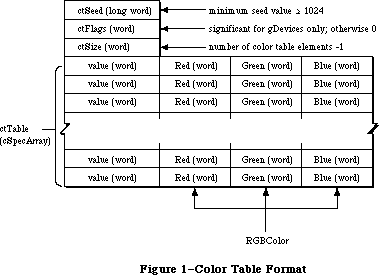 Figure 1–Color Table Format
Note that the colorSpec.value field of the record is only word size (16 bits), even though color index values (as returned by Color2Index) may be long words. The current implementation of Color QuickDraw only supports 16 bits. The components in an RGBColor are left-justified rather than right-justified in a word. Video drivers should respect this convention and extract the appropriate number of bits from the high order side of the component. For example, the Apple Graphics Card uses only the most significant eight bits of each component of the RGBColor record.
_______________________________________________________________________________
»Inverse Tables
Reader’s guide: The material in this section is provided for informational
and debugging purposes, since most programs won’t need to
use inverse tables.
For normal drawing, Color QuickDraw takes all specifications as absolute RGB triples, by means of the RGBColor record. Internally, these absolute specifications are converted to the appropriate values to be written into the video card. For direct devices, the RGB is separated into its red, green, and blue components, and each of these is written to the video card. On CLUT and fixed devices, however, there isn’t always a direct relationship between the specified RGB and the index value written into the frame buffer; in fact, on CLUT devices, the best-match index value may change dynamically as the colors available in the hardware are changed. On these types of devices, Color QuickDraw uses the Color Manager to find the best matches among the colors currently available.
The method used to determine the best available match can be specified by the application or the system on a gDevice by gDevice basis. By default, on CLUT and fixed devices, a special data structure called an inverse table is created. An inverse table is a table arranged in such a manner that, given an arbitrary RGB color, the pixel value can be very rapidly looked up.
In the default case, a certain number of the most significant bits of red, green, and blue are extracted, then concatenated together to form an index into the inverse table. At this location is the “best” match to the specified color. The number of bits per color channel that are used to construct this index is known as the resolution of the inverse table, and can be 3, 4, or 5 bits per channel. As the resolution of the inverse table increases, the number of permutations of possible colors increases, as does the size of the inverse table. Three-bit tables occupy 512 bytes, 4-bit tables (the default) occupy 4K bytes, and 5-bit tables occupy 32K bytes.
A disadvantage of this method is that certain colors that are “close” together can become hidden when they differ only in bits that weren’t used to construct the inverse table index. For example, even if the color table were loaded with 256 levels of gray, a 4-bit inverse table can only discriminate among 16 of the levels. To solve this problem without having to use special-case sets of colors with hidden colors, inverse tables carry additional information about how to find colors that differ only in the less significant bits. As a result, when the Color2Index routine is called, it can find the best match to the full 48-bit resolution available in a colorSpec. Since examining the extra information takes time, certain parts of Color QuickDraw, notably drawing in the arithmetic transfer modes, don’t use this information, and hence won’t find the hidden colors.
In most cases, when setting colors using RGBForeColor and RGBBackColor, and when using CopyBits to transfer pixMaps, inverse tables of four bits are sufficient. When using arithmetic transfer modes with certain color tables that have closely-spaced colors, the screen appearance may be improved by specifying inverse tables at 5-bit resolution. Because the format of inverse tables is subject to change in the future, or may not be present on certain devices, applications should not assume the structure of the data.
The data in inverse tables remains valid as long as the color table from which it was built remains unchanged. When a color table is modified, the inverse table must be rebuilt, and the screen should be redrawn to take advantage of this new information. Rather than being reconstructed when the color table is changed, the inverse table is marked invalid, and is automatically rebuilt when next accessed.
Rather than testing each entry of the color table to see if it has changed, the color-matching code compares the ctSeed of the current gDevice’s colorTable against the iTabSeed of that gDevice’s inverse table. Each routine that modifies the colorTable (with the exception of RestoreEntries) increments the ctSeed field of that colorTable. If the ctSeed and the iTabSeed don’t match, the inverse table is reconstructed for that gDevice.
Note: Under normal circumstances, all invalidations are posted and serviced
transparently to the application. This method of invalidation is the
same as that used to invalidate expanded patterns and cursors elsewhere
in Color QuickDraw.
In certain cases, it may be useful to override the inverse table matching code with custom routines that have special matching rules. See the section titled
“Custom Search and Complement Procedures” for more details.
The Color Manager performs a color table look-up in the following manner:
1. Builds a table of all possible RGB values;
2. For each position in the table, attempts to get the closest match;
3. Reduces the resolution of the lookup to four bits when constructing
the table, but later adds information to get a better resolution.
The Color Manager performs this table-building sequence whenever colors are requested by Color QuickDraw, the Color Picker, or the Palette Manager. This isn’t the only color matching method available; a custom search procedure, for example, may not have an inverse table. (See the section titled “Custom Search and Complement Procedures” for more information.) However, inverse tables are the default method for color matching.
When using an inverse table, the table is indexed by concatenating together the high-order bits of the three desired color components; iTabRes tells how many bits of each component are significant. The format of an inverse table is shown below:
TYPE
ITabHandle = ^ITabPtr;
ITabPtr = ^ITab;
ITab = RECORD
iTabSeed: LONGINT; {copy of color table seed}
iTabRes: INTEGER; {resolution of table}
iTTable: ARRAY[0..0] OF SignedByte {byte color }
{ table index values}
END;
The size of an index table in bytes is 2^3*iTabRes. The table below shows a sample index table:
resolution RGB color inverse-table size
index
4-bit red=$1234,
green=$5678,
blue=$9ABC $0159 2^12 = 4K bytes
5-bit red=$1234,
green=$5678,
blue=$9ABC $0953 2^15 = 32K bytes
MakeITable only supports 3-bit, 4-bit, and 5-bit resolution. Five bits is the maximum possible resolution, since the indices into a 6-bit table would have to be 18 bits long, more than a full word.
_______________________________________________________________________________
»USING THE COLOR MANAGER
_______________________________________________________________________________
In the simplest cases, use of the Color Manager is transparent when invoking the new Color QuickDraw routines. Using RGBForeColor and RGBBackColor, the program requests an RGB color for either the foreground or background. For instance, the following code requests an RGB color of red and sets it in the cGrafPort:
myColor.red:=$FFFF;
myColor.green:=0;
myColor.blue:=0;
RGBForeColor(myColor); {set pen red}
FrameRect(myRect); {draw in red}
Internally the Color Manager finds the best match to a color in TheGdevice’s current color table, and sets up the current cGrafPort to draw in this color. At this point, drawing operations can proceed using the selected colors.
The Color Manager routines described in this chapter are designed to operate on a single gDevice. The Palette Manager can perform most of these operations across multiple gDevices. Since the Palette Manager provides more general and portable functionality, applications should use Palette Manager routines whenever possible.
The SetEntries routine is used to change any part of or all of the entries in a device’s hardware Color Look-Up Table. The SaveEntries and RestoreEntries routines can make temporary changes to the color table under very specialized circumstances (such as a color selection dialog within an application). These routines aren’t needed under normal application circumstances.
SaveEntries allows any combination of colorSpecs to be copied into a special colorTable. RestoreEntries replaces the table created by SaveEntries into the graphics device. Unlike SetEntries, these routines don’t perform invalidations of the device’s colorTable, so they avoid causing invalidations of cached data structures. When these routines are used, the application must take responsibility for rebuilding and restoring auxiliary structures as necessary.
By convention, when using SetEntries or RestoreEntries, white should be located at color table position 0, and black should be stored in the last color table position available, whether it is 1, 3, 15, or 255. The Palette Manager also enforces this convention.
For precise control over color, or for dedicated color table entries, the Color Manager routines maintain special information in device color tables. Using ProtectEntry and ReserveEntry, an entry may be protected, which prevents SetEntries from further changing the entry, or reserved, which makes the entry unavailable to be matched by RGBForeColor and RGBBackColor. Routines that change the device table (SetEntries, ProtectEntry, and ReserveEntry, but not RestoreEntries) will perform the appropriate invalidations of QuickDraw data structures. The application must then redraw where necessary.
To inquire if a color exists in a color table, use RealColor. This tells whether an arbitrary color actually exists in the table for that gDevice.
Color2Index returns the index in the current device’s colorTable that is the best match to the requested color. Index2Color performs the opposite function—it returns the RGB of a particular index value. These routines can be useful when making copies of the screen frame buffer. InvertColor finds the complement of the provided color. GetSubTable performs a group Color2Index on a colorTable.
_______________________________________________________________________________
»COLOR MANAGER ROUTINES
_______________________________________________________________________________
The routines used for color drawing are covered in the chapter “Color
QuickDraw”. The Color Manager includes routines for color conversion, color table management, and error handling.
_______________________________________________________________________________
»Color Conversion
FUNCTION Color2Index (rgb: RGBColor): LONGINT;
The Color2Index routine finds the best available approximation to a given absolute color, using the list of search procedures in the current device record. It returns a longint, which is a pixel value padded with zeros in the high word. Since the colorSpec.value field is only a word, the result returned from Color2Index must be truncated to fit into a colorSpec. In pixMaps the
.value is the low-order word of this index.
Color2Index shouldn’t be called from a custom search procedure.
PROCEDURE Index2Color (index: LONGINT; VAR rgb: RGBColor);
The Index2Color routine finds the RGB color corresponding to a given color table index. The desired pixel value is passed and the corresponding RGB value is returned in RGB. The routine takes a longint, which should be a pixel value padded with zeros in the high word (normally the compiler does this automatically). Normally, the RGB from the current device color table corresponding to the index is returned as the RGBColor. Notice that this is not necessarily the same color that was originally requested via RGBForeColor, RGBBackColor, SetCPixel, or Color2Index. This RGB is read from the current gDevice color table.
PROCEDURE InvertColor (VAR theColor: RGBColor);
The InvertColor routine finds the complement of an absolute color, using the list of complement procedures in the current device record. The default complement procedure uses the 1’s complement of each component of the requested color.
FUNCTION RealColor (color: RGBColor) : BOOLEAN;
The RealColor routine tells whether a given absolute color actually exists in the current device’s color table. This decision is based on the current resolution of the inverse table. For example, if the current iTabRes is four, RealColor returns TRUE if there exists a color that exactly matches the top four bits of red, green, and blue.
PROCEDURE GetSubTable (myColors: CTabHandle; iTabRes:INTEGER;
targetTbl: CTabHandle);
The GetSubTable routine takes a ColorTable pointed at by myColors, and maps each RGB value into its nearest available match for each target table. These best matches are returned in the colorSpec.value fields of myColors. The values returned are best matches to the RGBColor in targetTbl and the returned indices are indices into targetTbl. Best matches are calculated using Color2Index and all applicable rules apply. A temporary inverse table is built, and then discarded. ITabRes controls the resolution of the iTable that is built. If targetTbl is NIL, then the current device’s color table is used, and the
device’s inverse table is used rather than building a new one. To provide a different resolution than the current inverse table, provide an explicit targetTbl parameter; don’t pass a NIL parameter.
Warning: Depending on the requested resolution, building the inverse table
can require large amounts of temporary space in the application
heap: twice the size of the table itself, plus a fixed overhead
for each inverse table resolution of 3–15K bytes.
PROCEDURE MakeITable (colorTab: CTabHandle; inverseTab: ITabHandle;
res: INTEGER);
The MakeITable routine generates an inverse table based on the current contents of the color table pointed to by CTabHandle, with a resolution of res bits per channel. Reserved color table pixel values are not included in the resultant color table. MakeITable tests its input parameters and will return an error in QDError if the resolution is less than three or greater than five. Passing a NIL parameter to CTabHandle or ITabHandle substitutes an appropriate handle from the current gDevice, while passing 0 for res substitutes the current gDevice’s preferred table resolution. These defaults can be used in any combination with explicit values, or with NIL parameters.
This routine allows maximum precision in matching colors, even if colors in the color table differ by less than the resolution of the inverse table. Five-bit inverse tables are not needed when drawing in normal QuickDraw modes. However, the new QuickDraw transfer modes (add, subtract, blend, etc.) may require a
5-bit inverse table for best results with certain color tables. MakeITable returns a QDError if the destination inverse table memory cannot be allocated. The 'mitq' resource governs how much memory is allocated for temporary internal structures; this resource type is for internal use only.
Warning: Depending on the requested resolution, building the inverse table
can require large amounts of temporary space in the application
heap: twice the size of the table itself, plus a fixed overhead
for each inverse table resolution of 3–15K bytes.
_______________________________________________________________________________
»Color Table Management
FUNCTION GetCTSeed : LONGINT;
The GetCTSeed function returns a unique seed value that can be used in the ctSeed field of a color table created by an application. This seed value guarantees that the color table will be recognized as distinct from the destination, and that color table translation will be performed properly. The return value will be greater than the value stored in minSeed.
PROCEDURE ProtectEntry (index: INTEGER; protect: BOOLEAN);
The ProtectEntry procedure protects or removes protection from an entry in the current device’s color table, depending on the value of the protect parameter. A protected entry can’t be changed by other clients. It returns a protection error if it attempts to protect an already protected entry. However, it can remove protection from any entry.
PROCEDURE ReserveEntry (index: INTEGER; reserve: BOOLEAN);
The ReserveEntry procedure reserves or dereserves an entry in the current color table, depending on the value of the reserve parameter. A reserved entry cannot be matched by another client’s search procedure, and will never be returned to another client by Color2Index or other routines that depend on it
(such as RGBForeColor, RGBBackColor, SetCPixel, and so forth). You could use this routine to selectively protect a color for color table animation.
ReserveEntry copies the low byte of gdID into the low byte of ColorSpec.value when reserving an entry, and leaves the high byte alone. It acts like a selective protection, and does not allow any changes if the current gdID is different than the one in the colorSpec.value field of the reserved entry. If a requested match is already reserved, ReserveEntry returns a protection error. Any entry can be dereserved.
PROCEDURE SetEntries(start, count: INTEGER; aTable: CSpecArray);
The SetEntries procedure sets a group of color table entries for the current gDevice, starting at a given position for the specified number of entries. The pointer aTable points into a cSpecArray, not into a color table. The colorSpec.value field of the entries must be in the logical range for the target card’s assigned pixel depth. Thus, with a 4-bit pixel size, the colorSpec.value fields should be in the range 1 to 15. With an 8-bit pixel size the range is 0 to 255. Note that all values are zero-based; for example, to set three entries, pass two in the count parameter.
Note: Palette Manager routines should be used instead of the SetEntries
routine for applications that will run in a multiscreen or
multitasking environment.
The SetEntries positional information works in logical space, rather than in the actual memory space used by the hardware. Requesting a change at position four in the color table may not modify color table entry four in the hardware, but it does correctly change the color on the screen for any pixels with a value of four in the video card. The SetEntries mode characterized by a start position and a length is called sequence mode. In this case, new colors are sequentially loaded into the hardware in the same order as the aTable, the clientID fields for changed entries are copied from the current device’s gdID field, and the colorSpec.value fields are ignored.
The other SetEntries mode is called index mode. It allows the cSpecArray to specify where the data will be installed on an entry-by-entry basis. To use this mode, pass –1 for the start position, with a valid count and a pointer to the cSpecArray. Each entry is installed into the color table at the position specified by the colorSpec.value field of each entry in the cSpecArray. In the current device’s color table, all changed entries’ colorSpec.value fields are assigned the gdID value.
When color table entries are changed, all cached fonts are invalidated, and the seed number is changed so that the next drawing operation will rebuild the inverse table. If any of the requested entries are protected or out of range, a protection error is returned, and nothing happens. If a requested entry is reserved, it can only be changed if the current gdID matches the low byte of the intended ColorSpec.value field.
PROCEDURE SaveEntries (srcTable: CTabHandle; ResultTable: CTabHandle;
VAR selection: ReqListRec);
SaveEntries saves a selection of entries from srcTable into resultTable. The entries to be set are enumerated in the selection parameter, which uses the ReqListRec data structure shown below. (These values are offsets into colorTable, not the contents of the colorSpec.value field.)
TYPE
ReqListRec = RECORD
reqLSize: INTEGER; {request list size –1}
reqLData: ARRAY [0..0] of INTEGER {request list data}
END;
If an entry is not present in srcTable, then that position of the requestList is set to colReqErr, and that position of resultTable has random values returned. If one or more entries are not found, then an error code is posted to QDError; however, for every entry in selection which is not colReqErr, the values in resultTable are valid. Note that srcTable and selection are assumed to have the same number of entries.
SaveEntries optionally allows NIL as its source color table parameter. If NIL is used, the current device’s color table is used as the source. The output of SaveEntries is the same as the input for RestoreEntries, except for the order.
PROCEDURE RestoreEntries (srcTable:CTabHandle;DstTable:CTabHandle;
VAR selection:ReqListRec);
RestoreEntries sets a selection of entries from srcTable into dstTable, but doesn’t rebuild the inverse table. The dstTable entries to be set are enumerated in the selection parameter, which uses the ReqListRec data structure shown in the SetEntries routine description. (These values are offsets into the srcTable, not the contents of the colorSpec.value field.)
If a request is beyond the end of the dstTable, that position of the requestList is set to colReqErr, and an error is returned. Note that srcTable and selection are assumed to have the same number of entries.
If dstTbl is NIL, or points to the device color table, the current device’s color table is updated, and the hardware is updated to these new colors. The seed is not changed, so no invalidation occurs (this may cause RGBForeColor to act strangely). This routine ignores protection and reservation of color table entries.
Generally, the Palette Manager is used to give an application its own set of colors; use of RestoreEntries should be limited to special-purpose applications. RestoreEntries allows you to change the colorTable without changing the ctSeed for the affected colorTable. You can execute the application code and then use RestoreEntries to put the original colors back in. However, in some cases things in the background may appear in the wrong colors, since they were never redrawn. To avoid this, the application must build its own new inverse table and redraw the background. If RestoreEntries were then used, the ctSeed would have to be explicitly changed to clean up correctly.
_______________________________________________________________________________
»Error Handling
FUNCTION QDError: INTEGER;
The QDError routine returns the error result from the last QuickDraw or Color Manager call. This routine is even more useful with 32-Bit QuickDraw. It is important that you check for errors after every QuickDraw call. For more information, see the 32-Bit QuickDraw documentation.
_______________________________________________________________________________
»CUSTOM SEARCH AND COMPLEMENT FUNCTIONS
_______________________________________________________________________________
The custom search function allows an application to override the inverse table matching code. The desired color is specified in the RGBColor field of a ColorSpec record and passed via a pointer on the stack; the procedure returns the corresponding pixel value in the ColorSpec.value field.
A custom search routine can provide its own matching rules. For instance, you might want to map all levels of green to a single green on a monitor. To do this, you could write and install a custom search procedure that is passed the RGB under question by the Color Manager. It can then analyze the color, and if it decides to act on this color, it can return the index of the desired shade of green. Otherwise, it can pass the color back to the Color Manager for matching, using the normal inverse table routine.
Many applications can share the same graphics device, each with its own custom search procedure. The procedures are chain elements in a linked list beginning in the gdSearchProc field of the gDevice port:
TYPE
SProcHndl = ^SProcPtr;
SProcPtr = ^SProcRec;;
SProcRec = RECORD
nxtSrch: SProcHndl; {handle to next sProcRec}
srchProc: ProcPtr {pointer to search procedure}
END;
Any number of search procedures can be installed in a linked list, each element of which will be called sequentially by the Color Manager, and given the chance to act or pass on the color. Since each device is a shared resource, a simple method (the gdID) is provided to identify the caller to the search procedures, as well as routines to add and delete custom procedures from the linked list.
The interface is as follows:
FUNCTION SearchProc (rgb: RGBColor; VAR position: LONGINT): BOOLEAN;
When attempting to approximate a color, the Color Manager calls each search procedure in the list until the boolean value returns as TRUE. The index value of the closest match is returned by the position parameter. If no search procedure installed in the linked list returns TRUE, the Color Manager calls the default search procedure.
The application can also supply a custom complement procedure to find the complement of a specified color. Complement procedures work the same as search procedures, and are kept in a list beginning in the gDevice port’s gdCompProc field.
TYPE
CProcHndl = ^CProcPtr;
CProcPtr = ^CProcRec;
CProcRec = RECORD
nxtComp: CProcHandle; {pointer to next CProcRec}
compProc: ProcPtr {pointer to complement procedure}
END;
The default complement procedure simply uses the 1’s complement of the RGB color components before looking them up in the inverse table. The interface is as follows:
FUNCTION CompProc (VAR rgb: RGBColor) : BOOLEAN;
_______________________________________________________________________________
»Operations on Search and Complement Functions
PROCEDURE AddSearch (searchProc: ProcPtr);
PROCEDURE AddComp (compProc: ProcPtr);
The AddSearch and AddComp routines add a procedure to the head of the current device record’s list of search or complement procedures. These routines allocate an SProcRec or CProcRec.
PROCEDURE DelSearch (searchProc: ProcPtr);
PROCEDURE DelComp (compProc: ProcPtr);
The DelSearch and DelComp procedures remove a custom search or complement procedure from the current device record’s list of search or complement procedures. These routines dispose of the chain element, but do nothing to the procPtr.
PROCEDURE SetClientID (id: INTEGER);
The SetClientID procedure sets the gdID field in the current device record to identify this client program to its search and complement procedures.
_______________________________________________________________________________
»SUMMARY OF THE COLOR MANAGER
_______________________________________________________________________________
Constants
CONST
minSeed = 1023; {minimum seed value for ctSeed}
_______________________________________________________________________________
Data Types
TYPE
ITabHandle = ^ITabPtr;
ITabPtr = ^ITab;
ITab = RECORD
iTabSeed: LONGINT; {copy of color table seed}
iTabRes: INTEGER; {resolution of table}
iTTable: ARRAY[0..0] OF SignedByte {byte color }
{ table index values}
END;
SProcHndl = ^SProcPtr;
SProcPtr = ^SProcRec;;
SProcRec = RECORD
nxtSrch: SProcHndl; {handle to next sProcRec}
srchProc: ProcPtr {pointer to search procedure}
END;
CProcHndl = ^CProcPtr;
CProcPtr = ^CProcRec;
CProcRec = RECORD
nxtComp: CProcHandle; {pointer to next CProcRec}
compProc: ProcPtr {pointer to complement procedure}
END;
ReqListRec = RECORD
reqLSize: INTEGER; {request list size –1}
reqLData: ARRAY [0..0] of INTEGER {request list data}
END;
_______________________________________________________________________________
Routines
Color Conversion
FUNCTION Color2Index (VAR rgb: RGBColor): LONGINT;
PROCEDURE Index2Color (index: LONGINT; VAR rgb: RGBColor);
PROCEDURE InvertColor (VAR theColor: RGBColor);
FUNCTION RealColor (color: RGBColor) : BOOLEAN;
PROCEDURE GetSubTable (myColors: CTabHandle; iTabRes: INTEGER;
targetTbl:CTabHandle);
PROCEDURE MakeITable (colorTab: CTabHandle; inverseTab: ITabHandle;
res: INTEGER);
Color Table Management
FUNCTION GetCTSeed: LONGINT;
PROCEDURE ProtectEntry (index: INTEGER; protect: BOOLEAN);
PROCEDURE ReserveEntry (index: INTEGER; reserve: BOOLEAN);
PROCEDURE SetEntries (start, count: INTEGER; aTable: cSpecArray);
PROCEDURE RestoreEntries (srcTable:CTabHandle;dstTable:CTabHandle;
VAR selection:ReqListRec);
PROCEDURE SaveEntries (srcTable:CTabHandle;resultTable:CTabHandle; VAR selection:ReqListRec)
Operations on Search and Complement Functions
PROCEDURE AddSearch (searchProc: ProcPtr);
PROCEDURE AddComp (compProc: ProcPtr);
PROCEDURE DelSearch (searchProc: ProcPtr);
PROCEDURE DelComp (compProc: ProcPtr);
PROCEDURE SetClientID (id: INTEGER);
Error Handling
FUNCTION QDError: INTEGER;
_______________________________________________________________________________
Assembly Language Information
Constants
minSeed EQU 1023 ;minimum ctSeed value
ITab structure
iTabSeed EQU $0 ;[long] ID of owning color table
iTabRes EQU $4 ;[word] client ID
iTTable EQU $6 ;table of indices starts here
;in this version, entries are BYTE
SProcRec structure
nxtSrch EQU $0 ;[pointer] link to next proc
srchProc EQU $4 ;[pointer] pointer to routine
CProcRec structure
nxtComp EQU $0 ;[pointer] link to next proc
compProc EQU $4 ;[pointer] pointer to routine
Request list structure
reqLSize EQU 0 ;[word] request list size –1
reqLData EQU 2 ;[word] request list data
Further Reference:
_______________________________________________________________________________
Color QuickDraw
Graphics Devices
Palette Manager
Color Picker Package
32-Bit QuickDraw Documentation
Figure 1–Color Table Format
Note that the colorSpec.value field of the record is only word size (16 bits), even though color index values (as returned by Color2Index) may be long words. The current implementation of Color QuickDraw only supports 16 bits. The components in an RGBColor are left-justified rather than right-justified in a word. Video drivers should respect this convention and extract the appropriate number of bits from the high order side of the component. For example, the Apple Graphics Card uses only the most significant eight bits of each component of the RGBColor record.
_______________________________________________________________________________
»Inverse Tables
Reader’s guide: The material in this section is provided for informational
and debugging purposes, since most programs won’t need to
use inverse tables.
For normal drawing, Color QuickDraw takes all specifications as absolute RGB triples, by means of the RGBColor record. Internally, these absolute specifications are converted to the appropriate values to be written into the video card. For direct devices, the RGB is separated into its red, green, and blue components, and each of these is written to the video card. On CLUT and fixed devices, however, there isn’t always a direct relationship between the specified RGB and the index value written into the frame buffer; in fact, on CLUT devices, the best-match index value may change dynamically as the colors available in the hardware are changed. On these types of devices, Color QuickDraw uses the Color Manager to find the best matches among the colors currently available.
The method used to determine the best available match can be specified by the application or the system on a gDevice by gDevice basis. By default, on CLUT and fixed devices, a special data structure called an inverse table is created. An inverse table is a table arranged in such a manner that, given an arbitrary RGB color, the pixel value can be very rapidly looked up.
In the default case, a certain number of the most significant bits of red, green, and blue are extracted, then concatenated together to form an index into the inverse table. At this location is the “best” match to the specified color. The number of bits per color channel that are used to construct this index is known as the resolution of the inverse table, and can be 3, 4, or 5 bits per channel. As the resolution of the inverse table increases, the number of permutations of possible colors increases, as does the size of the inverse table. Three-bit tables occupy 512 bytes, 4-bit tables (the default) occupy 4K bytes, and 5-bit tables occupy 32K bytes.
A disadvantage of this method is that certain colors that are “close” together can become hidden when they differ only in bits that weren’t used to construct the inverse table index. For example, even if the color table were loaded with 256 levels of gray, a 4-bit inverse table can only discriminate among 16 of the levels. To solve this problem without having to use special-case sets of colors with hidden colors, inverse tables carry additional information about how to find colors that differ only in the less significant bits. As a result, when the Color2Index routine is called, it can find the best match to the full 48-bit resolution available in a colorSpec. Since examining the extra information takes time, certain parts of Color QuickDraw, notably drawing in the arithmetic transfer modes, don’t use this information, and hence won’t find the hidden colors.
In most cases, when setting colors using RGBForeColor and RGBBackColor, and when using CopyBits to transfer pixMaps, inverse tables of four bits are sufficient. When using arithmetic transfer modes with certain color tables that have closely-spaced colors, the screen appearance may be improved by specifying inverse tables at 5-bit resolution. Because the format of inverse tables is subject to change in the future, or may not be present on certain devices, applications should not assume the structure of the data.
The data in inverse tables remains valid as long as the color table from which it was built remains unchanged. When a color table is modified, the inverse table must be rebuilt, and the screen should be redrawn to take advantage of this new information. Rather than being reconstructed when the color table is changed, the inverse table is marked invalid, and is automatically rebuilt when next accessed.
Rather than testing each entry of the color table to see if it has changed, the color-matching code compares the ctSeed of the current gDevice’s colorTable against the iTabSeed of that gDevice’s inverse table. Each routine that modifies the colorTable (with the exception of RestoreEntries) increments the ctSeed field of that colorTable. If the ctSeed and the iTabSeed don’t match, the inverse table is reconstructed for that gDevice.
Note: Under normal circumstances, all invalidations are posted and serviced
transparently to the application. This method of invalidation is the
same as that used to invalidate expanded patterns and cursors elsewhere
in Color QuickDraw.
In certain cases, it may be useful to override the inverse table matching code with custom routines that have special matching rules. See the section titled
“Custom Search and Complement Procedures” for more details.
The Color Manager performs a color table look-up in the following manner:
1. Builds a table of all possible RGB values;
2. For each position in the table, attempts to get the closest match;
3. Reduces the resolution of the lookup to four bits when constructing
the table, but later adds information to get a better resolution.
The Color Manager performs this table-building sequence whenever colors are requested by Color QuickDraw, the Color Picker, or the Palette Manager. This isn’t the only color matching method available; a custom search procedure, for example, may not have an inverse table. (See the section titled “Custom Search and Complement Procedures” for more information.) However, inverse tables are the default method for color matching.
When using an inverse table, the table is indexed by concatenating together the high-order bits of the three desired color components; iTabRes tells how many bits of each component are significant. The format of an inverse table is shown below:
TYPE
ITabHandle = ^ITabPtr;
ITabPtr = ^ITab;
ITab = RECORD
iTabSeed: LONGINT; {copy of color table seed}
iTabRes: INTEGER; {resolution of table}
iTTable: ARRAY[0..0] OF SignedByte {byte color }
{ table index values}
END;
The size of an index table in bytes is 2^3*iTabRes. The table below shows a sample index table:
resolution RGB color inverse-table size
index
4-bit red=$1234,
green=$5678,
blue=$9ABC $0159 2^12 = 4K bytes
5-bit red=$1234,
green=$5678,
blue=$9ABC $0953 2^15 = 32K bytes
MakeITable only supports 3-bit, 4-bit, and 5-bit resolution. Five bits is the maximum possible resolution, since the indices into a 6-bit table would have to be 18 bits long, more than a full word.
_______________________________________________________________________________
»USING THE COLOR MANAGER
_______________________________________________________________________________
In the simplest cases, use of the Color Manager is transparent when invoking the new Color QuickDraw routines. Using RGBForeColor and RGBBackColor, the program requests an RGB color for either the foreground or background. For instance, the following code requests an RGB color of red and sets it in the cGrafPort:
myColor.red:=$FFFF;
myColor.green:=0;
myColor.blue:=0;
RGBForeColor(myColor); {set pen red}
FrameRect(myRect); {draw in red}
Internally the Color Manager finds the best match to a color in TheGdevice’s current color table, and sets up the current cGrafPort to draw in this color. At this point, drawing operations can proceed using the selected colors.
The Color Manager routines described in this chapter are designed to operate on a single gDevice. The Palette Manager can perform most of these operations across multiple gDevices. Since the Palette Manager provides more general and portable functionality, applications should use Palette Manager routines whenever possible.
The SetEntries routine is used to change any part of or all of the entries in a device’s hardware Color Look-Up Table. The SaveEntries and RestoreEntries routines can make temporary changes to the color table under very specialized circumstances (such as a color selection dialog within an application). These routines aren’t needed under normal application circumstances.
SaveEntries allows any combination of colorSpecs to be copied into a special colorTable. RestoreEntries replaces the table created by SaveEntries into the graphics device. Unlike SetEntries, these routines don’t perform invalidations of the device’s colorTable, so they avoid causing invalidations of cached data structures. When these routines are used, the application must take responsibility for rebuilding and restoring auxiliary structures as necessary.
By convention, when using SetEntries or RestoreEntries, white should be located at color table position 0, and black should be stored in the last color table position available, whether it is 1, 3, 15, or 255. The Palette Manager also enforces this convention.
For precise control over color, or for dedicated color table entries, the Color Manager routines maintain special information in device color tables. Using ProtectEntry and ReserveEntry, an entry may be protected, which prevents SetEntries from further changing the entry, or reserved, which makes the entry unavailable to be matched by RGBForeColor and RGBBackColor. Routines that change the device table (SetEntries, ProtectEntry, and ReserveEntry, but not RestoreEntries) will perform the appropriate invalidations of QuickDraw data structures. The application must then redraw where necessary.
To inquire if a color exists in a color table, use RealColor. This tells whether an arbitrary color actually exists in the table for that gDevice.
Color2Index returns the index in the current device’s colorTable that is the best match to the requested color. Index2Color performs the opposite function—it returns the RGB of a particular index value. These routines can be useful when making copies of the screen frame buffer. InvertColor finds the complement of the provided color. GetSubTable performs a group Color2Index on a colorTable.
_______________________________________________________________________________
»COLOR MANAGER ROUTINES
_______________________________________________________________________________
The routines used for color drawing are covered in the chapter “Color
QuickDraw”. The Color Manager includes routines for color conversion, color table management, and error handling.
_______________________________________________________________________________
»Color Conversion
FUNCTION Color2Index (rgb: RGBColor): LONGINT;
The Color2Index routine finds the best available approximation to a given absolute color, using the list of search procedures in the current device record. It returns a longint, which is a pixel value padded with zeros in the high word. Since the colorSpec.value field is only a word, the result returned from Color2Index must be truncated to fit into a colorSpec. In pixMaps the
.value is the low-order word of this index.
Color2Index shouldn’t be called from a custom search procedure.
PROCEDURE Index2Color (index: LONGINT; VAR rgb: RGBColor);
The Index2Color routine finds the RGB color corresponding to a given color table index. The desired pixel value is passed and the corresponding RGB value is returned in RGB. The routine takes a longint, which should be a pixel value padded with zeros in the high word (normally the compiler does this automatically). Normally, the RGB from the current device color table corresponding to the index is returned as the RGBColor. Notice that this is not necessarily the same color that was originally requested via RGBForeColor, RGBBackColor, SetCPixel, or Color2Index. This RGB is read from the current gDevice color table.
PROCEDURE InvertColor (VAR theColor: RGBColor);
The InvertColor routine finds the complement of an absolute color, using the list of complement procedures in the current device record. The default complement procedure uses the 1’s complement of each component of the requested color.
FUNCTION RealColor (color: RGBColor) : BOOLEAN;
The RealColor routine tells whether a given absolute color actually exists in the current device’s color table. This decision is based on the current resolution of the inverse table. For example, if the current iTabRes is four, RealColor returns TRUE if there exists a color that exactly matches the top four bits of red, green, and blue.
PROCEDURE GetSubTable (myColors: CTabHandle; iTabRes:INTEGER;
targetTbl: CTabHandle);
The GetSubTable routine takes a ColorTable pointed at by myColors, and maps each RGB value into its nearest available match for each target table. These best matches are returned in the colorSpec.value fields of myColors. The values returned are best matches to the RGBColor in targetTbl and the returned indices are indices into targetTbl. Best matches are calculated using Color2Index and all applicable rules apply. A temporary inverse table is built, and then discarded. ITabRes controls the resolution of the iTable that is built. If targetTbl is NIL, then the current device’s color table is used, and the
device’s inverse table is used rather than building a new one. To provide a different resolution than the current inverse table, provide an explicit targetTbl parameter; don’t pass a NIL parameter.
Warning: Depending on the requested resolution, building the inverse table
can require large amounts of temporary space in the application
heap: twice the size of the table itself, plus a fixed overhead
for each inverse table resolution of 3–15K bytes.
PROCEDURE MakeITable (colorTab: CTabHandle; inverseTab: ITabHandle;
res: INTEGER);
The MakeITable routine generates an inverse table based on the current contents of the color table pointed to by CTabHandle, with a resolution of res bits per channel. Reserved color table pixel values are not included in the resultant color table. MakeITable tests its input parameters and will return an error in QDError if the resolution is less than three or greater than five. Passing a NIL parameter to CTabHandle or ITabHandle substitutes an appropriate handle from the current gDevice, while passing 0 for res substitutes the current gDevice’s preferred table resolution. These defaults can be used in any combination with explicit values, or with NIL parameters.
This routine allows maximum precision in matching colors, even if colors in the color table differ by less than the resolution of the inverse table. Five-bit inverse tables are not needed when drawing in normal QuickDraw modes. However, the new QuickDraw transfer modes (add, subtract, blend, etc.) may require a
5-bit inverse table for best results with certain color tables. MakeITable returns a QDError if the destination inverse table memory cannot be allocated. The 'mitq' resource governs how much memory is allocated for temporary internal structures; this resource type is for internal use only.
Warning: Depending on the requested resolution, building the inverse table
can require large amounts of temporary space in the application
heap: twice the size of the table itself, plus a fixed overhead
for each inverse table resolution of 3–15K bytes.
_______________________________________________________________________________
»Color Table Management
FUNCTION GetCTSeed : LONGINT;
The GetCTSeed function returns a unique seed value that can be used in the ctSeed field of a color table created by an application. This seed value guarantees that the color table will be recognized as distinct from the destination, and that color table translation will be performed properly. The return value will be greater than the value stored in minSeed.
PROCEDURE ProtectEntry (index: INTEGER; protect: BOOLEAN);
The ProtectEntry procedure protects or removes protection from an entry in the current device’s color table, depending on the value of the protect parameter. A protected entry can’t be changed by other clients. It returns a protection error if it attempts to protect an already protected entry. However, it can remove protection from any entry.
PROCEDURE ReserveEntry (index: INTEGER; reserve: BOOLEAN);
The ReserveEntry procedure reserves or dereserves an entry in the current color table, depending on the value of the reserve parameter. A reserved entry cannot be matched by another client’s search procedure, and will never be returned to another client by Color2Index or other routines that depend on it
(such as RGBForeColor, RGBBackColor, SetCPixel, and so forth). You could use this routine to selectively protect a color for color table animation.
ReserveEntry copies the low byte of gdID into the low byte of ColorSpec.value when reserving an entry, and leaves the high byte alone. It acts like a selective protection, and does not allow any changes if the current gdID is different than the one in the colorSpec.value field of the reserved entry. If a requested match is already reserved, ReserveEntry returns a protection error. Any entry can be dereserved.
PROCEDURE SetEntries(start, count: INTEGER; aTable: CSpecArray);
The SetEntries procedure sets a group of color table entries for the current gDevice, starting at a given position for the specified number of entries. The pointer aTable points into a cSpecArray, not into a color table. The colorSpec.value field of the entries must be in the logical range for the target card’s assigned pixel depth. Thus, with a 4-bit pixel size, the colorSpec.value fields should be in the range 1 to 15. With an 8-bit pixel size the range is 0 to 255. Note that all values are zero-based; for example, to set three entries, pass two in the count parameter.
Note: Palette Manager routines should be used instead of the SetEntries
routine for applications that will run in a multiscreen or
multitasking environment.
The SetEntries positional information works in logical space, rather than in the actual memory space used by the hardware. Requesting a change at position four in the color table may not modify color table entry four in the hardware, but it does correctly change the color on the screen for any pixels with a value of four in the video card. The SetEntries mode characterized by a start position and a length is called sequence mode. In this case, new colors are sequentially loaded into the hardware in the same order as the aTable, the clientID fields for changed entries are copied from the current device’s gdID field, and the colorSpec.value fields are ignored.
The other SetEntries mode is called index mode. It allows the cSpecArray to specify where the data will be installed on an entry-by-entry basis. To use this mode, pass –1 for the start position, with a valid count and a pointer to the cSpecArray. Each entry is installed into the color table at the position specified by the colorSpec.value field of each entry in the cSpecArray. In the current device’s color table, all changed entries’ colorSpec.value fields are assigned the gdID value.
When color table entries are changed, all cached fonts are invalidated, and the seed number is changed so that the next drawing operation will rebuild the inverse table. If any of the requested entries are protected or out of range, a protection error is returned, and nothing happens. If a requested entry is reserved, it can only be changed if the current gdID matches the low byte of the intended ColorSpec.value field.
PROCEDURE SaveEntries (srcTable: CTabHandle; ResultTable: CTabHandle;
VAR selection: ReqListRec);
SaveEntries saves a selection of entries from srcTable into resultTable. The entries to be set are enumerated in the selection parameter, which uses the ReqListRec data structure shown below. (These values are offsets into colorTable, not the contents of the colorSpec.value field.)
TYPE
ReqListRec = RECORD
reqLSize: INTEGER; {request list size –1}
reqLData: ARRAY [0..0] of INTEGER {request list data}
END;
If an entry is not present in srcTable, then that position of the requestList is set to colReqErr, and that position of resultTable has random values returned. If one or more entries are not found, then an error code is posted to QDError; however, for every entry in selection which is not colReqErr, the values in resultTable are valid. Note that srcTable and selection are assumed to have the same number of entries.
SaveEntries optionally allows NIL as its source color table parameter. If NIL is used, the current device’s color table is used as the source. The output of SaveEntries is the same as the input for RestoreEntries, except for the order.
PROCEDURE RestoreEntries (srcTable:CTabHandle;DstTable:CTabHandle;
VAR selection:ReqListRec);
RestoreEntries sets a selection of entries from srcTable into dstTable, but doesn’t rebuild the inverse table. The dstTable entries to be set are enumerated in the selection parameter, which uses the ReqListRec data structure shown in the SetEntries routine description. (These values are offsets into the srcTable, not the contents of the colorSpec.value field.)
If a request is beyond the end of the dstTable, that position of the requestList is set to colReqErr, and an error is returned. Note that srcTable and selection are assumed to have the same number of entries.
If dstTbl is NIL, or points to the device color table, the current device’s color table is updated, and the hardware is updated to these new colors. The seed is not changed, so no invalidation occurs (this may cause RGBForeColor to act strangely). This routine ignores protection and reservation of color table entries.
Generally, the Palette Manager is used to give an application its own set of colors; use of RestoreEntries should be limited to special-purpose applications. RestoreEntries allows you to change the colorTable without changing the ctSeed for the affected colorTable. You can execute the application code and then use RestoreEntries to put the original colors back in. However, in some cases things in the background may appear in the wrong colors, since they were never redrawn. To avoid this, the application must build its own new inverse table and redraw the background. If RestoreEntries were then used, the ctSeed would have to be explicitly changed to clean up correctly.
_______________________________________________________________________________
»Error Handling
FUNCTION QDError: INTEGER;
The QDError routine returns the error result from the last QuickDraw or Color Manager call. This routine is even more useful with 32-Bit QuickDraw. It is important that you check for errors after every QuickDraw call. For more information, see the 32-Bit QuickDraw documentation.
_______________________________________________________________________________
»CUSTOM SEARCH AND COMPLEMENT FUNCTIONS
_______________________________________________________________________________
The custom search function allows an application to override the inverse table matching code. The desired color is specified in the RGBColor field of a ColorSpec record and passed via a pointer on the stack; the procedure returns the corresponding pixel value in the ColorSpec.value field.
A custom search routine can provide its own matching rules. For instance, you might want to map all levels of green to a single green on a monitor. To do this, you could write and install a custom search procedure that is passed the RGB under question by the Color Manager. It can then analyze the color, and if it decides to act on this color, it can return the index of the desired shade of green. Otherwise, it can pass the color back to the Color Manager for matching, using the normal inverse table routine.
Many applications can share the same graphics device, each with its own custom search procedure. The procedures are chain elements in a linked list beginning in the gdSearchProc field of the gDevice port:
TYPE
SProcHndl = ^SProcPtr;
SProcPtr = ^SProcRec;;
SProcRec = RECORD
nxtSrch: SProcHndl; {handle to next sProcRec}
srchProc: ProcPtr {pointer to search procedure}
END;
Any number of search procedures can be installed in a linked list, each element of which will be called sequentially by the Color Manager, and given the chance to act or pass on the color. Since each device is a shared resource, a simple method (the gdID) is provided to identify the caller to the search procedures, as well as routines to add and delete custom procedures from the linked list.
The interface is as follows:
FUNCTION SearchProc (rgb: RGBColor; VAR position: LONGINT): BOOLEAN;
When attempting to approximate a color, the Color Manager calls each search procedure in the list until the boolean value returns as TRUE. The index value of the closest match is returned by the position parameter. If no search procedure installed in the linked list returns TRUE, the Color Manager calls the default search procedure.
The application can also supply a custom complement procedure to find the complement of a specified color. Complement procedures work the same as search procedures, and are kept in a list beginning in the gDevice port’s gdCompProc field.
TYPE
CProcHndl = ^CProcPtr;
CProcPtr = ^CProcRec;
CProcRec = RECORD
nxtComp: CProcHandle; {pointer to next CProcRec}
compProc: ProcPtr {pointer to complement procedure}
END;
The default complement procedure simply uses the 1’s complement of the RGB color components before looking them up in the inverse table. The interface is as follows:
FUNCTION CompProc (VAR rgb: RGBColor) : BOOLEAN;
_______________________________________________________________________________
»Operations on Search and Complement Functions
PROCEDURE AddSearch (searchProc: ProcPtr);
PROCEDURE AddComp (compProc: ProcPtr);
The AddSearch and AddComp routines add a procedure to the head of the current device record’s list of search or complement procedures. These routines allocate an SProcRec or CProcRec.
PROCEDURE DelSearch (searchProc: ProcPtr);
PROCEDURE DelComp (compProc: ProcPtr);
The DelSearch and DelComp procedures remove a custom search or complement procedure from the current device record’s list of search or complement procedures. These routines dispose of the chain element, but do nothing to the procPtr.
PROCEDURE SetClientID (id: INTEGER);
The SetClientID procedure sets the gdID field in the current device record to identify this client program to its search and complement procedures.
_______________________________________________________________________________
»SUMMARY OF THE COLOR MANAGER
_______________________________________________________________________________
Constants
CONST
minSeed = 1023; {minimum seed value for ctSeed}
_______________________________________________________________________________
Data Types
TYPE
ITabHandle = ^ITabPtr;
ITabPtr = ^ITab;
ITab = RECORD
iTabSeed: LONGINT; {copy of color table seed}
iTabRes: INTEGER; {resolution of table}
iTTable: ARRAY[0..0] OF SignedByte {byte color }
{ table index values}
END;
SProcHndl = ^SProcPtr;
SProcPtr = ^SProcRec;;
SProcRec = RECORD
nxtSrch: SProcHndl; {handle to next sProcRec}
srchProc: ProcPtr {pointer to search procedure}
END;
CProcHndl = ^CProcPtr;
CProcPtr = ^CProcRec;
CProcRec = RECORD
nxtComp: CProcHandle; {pointer to next CProcRec}
compProc: ProcPtr {pointer to complement procedure}
END;
ReqListRec = RECORD
reqLSize: INTEGER; {request list size –1}
reqLData: ARRAY [0..0] of INTEGER {request list data}
END;
_______________________________________________________________________________
Routines
Color Conversion
FUNCTION Color2Index (VAR rgb: RGBColor): LONGINT;
PROCEDURE Index2Color (index: LONGINT; VAR rgb: RGBColor);
PROCEDURE InvertColor (VAR theColor: RGBColor);
FUNCTION RealColor (color: RGBColor) : BOOLEAN;
PROCEDURE GetSubTable (myColors: CTabHandle; iTabRes: INTEGER;
targetTbl:CTabHandle);
PROCEDURE MakeITable (colorTab: CTabHandle; inverseTab: ITabHandle;
res: INTEGER);
Color Table Management
FUNCTION GetCTSeed: LONGINT;
PROCEDURE ProtectEntry (index: INTEGER; protect: BOOLEAN);
PROCEDURE ReserveEntry (index: INTEGER; reserve: BOOLEAN);
PROCEDURE SetEntries (start, count: INTEGER; aTable: cSpecArray);
PROCEDURE RestoreEntries (srcTable:CTabHandle;dstTable:CTabHandle;
VAR selection:ReqListRec);
PROCEDURE SaveEntries (srcTable:CTabHandle;resultTable:CTabHandle; VAR selection:ReqListRec)
Operations on Search and Complement Functions
PROCEDURE AddSearch (searchProc: ProcPtr);
PROCEDURE AddComp (compProc: ProcPtr);
PROCEDURE DelSearch (searchProc: ProcPtr);
PROCEDURE DelComp (compProc: ProcPtr);
PROCEDURE SetClientID (id: INTEGER);
Error Handling
FUNCTION QDError: INTEGER;
_______________________________________________________________________________
Assembly Language Information
Constants
minSeed EQU 1023 ;minimum ctSeed value
ITab structure
iTabSeed EQU $0 ;[long] ID of owning color table
iTabRes EQU $4 ;[word] client ID
iTTable EQU $6 ;table of indices starts here
;in this version, entries are BYTE
SProcRec structure
nxtSrch EQU $0 ;[pointer] link to next proc
srchProc EQU $4 ;[pointer] pointer to routine
CProcRec structure
nxtComp EQU $0 ;[pointer] link to next proc
compProc EQU $4 ;[pointer] pointer to routine
Request list structure
reqLSize EQU 0 ;[word] request list size –1
reqLData EQU 2 ;[word] request list data
Further Reference:
_______________________________________________________________________________
Color QuickDraw
Graphics Devices
Palette Manager
Color Picker Package
32-Bit QuickDraw Documentation
The Color Picker Package
_______________________________________________________________________________
THE COLOR PICKER PACKAGE
_______________________________________________________________________________
About This Chapter
The Color Picker Package
The Color Picker Dialog Box
Color Picker Package Routines
Conversion Facilities
Summary of the Color Picker Package
_______________________________________________________________________________
»ABOUT THIS CHAPTER
_______________________________________________________________________________
Warning: This chapter has not been updated to reflect changes and improvements
that are available on systems using 32-Bit QuickDraw. For further
information on 32-Bit QuickDraw, please refer to the 32-Bit QuickDraw
documentation (available on “Phil & Dave’s Excellent CD: The Release
Version).
This chapter describes the Color Picker, a package that allows applications to present users with a standard interface for color selection. You should be familiar with color on the Macintosh and graphic devices, as discussed in the Color QuickDraw and Graphic Devices chapters.
_______________________________________________________________________________
»THE COLOR PICKER PACKAGE
_______________________________________________________________________________
The Color Picker Package is a tool that applications can use to present a standard user interface for color selection. It also provides routines for converting color values between several different color systems. The Color Picker Package does not alter the Color Look-Up Table (CLUT), if any, associated with the current graphics device.
Once the user chooses a color, Color Picker returns it to the application, in the form of an RGBColor value, leaving the graphics device in its original state. The application can do what it likes with the color selection, with as much or as little attention to the available graphics hardware as it deems appropriate. On black and white hardware (or in less than 4-bit mode), the display is in black and white; Color Picker returns the value selected, but does not call any color routines.
On direct device hardware the exact color can be used without extra effort, while on fixed CLUT hardware it can only be approximated. On most hardware, such as Apple’s TFB graphics card, which has a variable CLUT, the application decides how faithfully to reproduce the color, because it can replace an entry in the device’s CLUT to show it exactly, or treat the table as fixed and approximate the color. Color Picker itself takes advantage of the hardware on such devices, displaying the exact color by borrowing a color table entry. As result, applications that are content to approximate the color will show users colors that differ somewhat from the ones picked.
_______________________________________________________________________________
»THE COLOR PICKER DIALOG BOX
_______________________________________________________________________________
Developers can present the Color Picker dialog box, shown in Figures 1 & 2
(This illustration is in color in Figure 1 if you are using a color monitor in color mode.), to a user by means of the Color Picker routine, described later in this chapter.
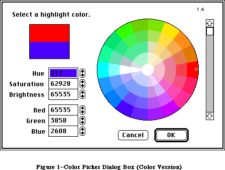 Figure 1–Color Picker Dialog Box (Color Version)
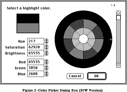 Figure 2–Color Picker Dialog Box (B/W Version)
When called by an application, the Color Picker supplies the prompt text, which appears in the upper-left corner, and the initial color, which appears in the bottom of the two rectangles below the prompt. The color being picked, in the upper rectangle, ranges rapidly over the entire color space, in response to the controls in the rest of the dialog. The calling application also supplies the location of the top-left corner of the dialog window.
The user is allowed to select a single color, from the entire range the hardware can produce. The wheel allows users to select a given hue and saturation simultaneously. The center of the wheel displays zero saturation
(no hue mixed in); the outer boundary is maximum saturation (no gray mixed in); colors on the edge of the wheel are pure hues. The scroll bar at right controls the brightness (value) of the wheel.
The two groups of text fields (Hue/Saturation/Brightness and Red/Green/Blue) show the parameters of the color being picked in two independent color systems. Brightness represents value in the HSV model.
The HSV values are the primary color system, which correspond to the controls in the dialog box. The RGB values are the alternate color system, and the way they vary in response to the dialog controls is not intuitive. Only users who understand both color systems will understand how the RGB values vary in relation to the rest of the dialog. (See the Color Quickdraw chapter for more information.) The alternate color system is intended to make life easier for users accustomed to something other than the HSV model.
The range for all of the component values is 0 to 65,535. Larger values are clipped to the maximum after the user exits the field. When incrementing or decrementing the hue via the arrow controls, 0 wraps around to 65,535, and vice versa, so the user can circumnavigate the wheel unimpeded. The hue value for red is 0; green is 21,845; blue is 43,690.
_______________________________________________________________________________
»COLOR PICKER PACKAGE ROUTINES
_______________________________________________________________________________
FUNCTION GetColor(where: Point; prompt: Str255; inColor: RGBColor;
VAR outColor: RGBColor) : BOOLEAN;
GetColor displays the Color Picker dialog box on the screen, with its top-left corner located at where. (The where Point should be on the main gDevice.) If where = (0,0), the dialog box is positioned neatly on the screen, centered horizontally, and with one third of the empty space above the box, two thirds below, whatever the screen size.
The prompt string is displayed in the upper-left corner of the dialog box. InColor is the starting color, which the user may want for comparison, and is displayed immediately below the current output color (the one the user is picking). OutColor is set to the last color value the user picked, if and only if the user clicks OK. On entry, it is treated as undefined, so the output color sample originally matches the input. While the color being picked may vary widely, the input color sample remains fixed, and clicking in the input sample resets the output color sample to match it.
GetColor returns TRUE if the user exits via the OK button, or FALSE if the user cancels.
Assembly-language note: the trap macro for the Color Picker Package is
_Pack12. The routine selectors are as follows:
Fix2SmallFract .EQU 1
SmallFract2Fix .EQU 2
CMY2RGB .EQU 3
RGB2CMY .EQU 4
HSL2RGB .EQU 5
RGB2HSL .EQU 6
HSV2RGB .EQU 7
RGB2HSV .EQU 8
GetColor .EQU 9
_______________________________________________________________________________
»CONVERSION FACILITIES
_______________________________________________________________________________
The Color Picker provides six procedures for converting color values between CMY and RGB, and between HSL or HSV and RGB. Most developers will not need to use these routines.
PROCEDURE CMY2RGB (cColor: CMYColor; VAR rColor: RGBColor);
PROCEDURE RGB2CMY (rColor: RGBColor; VAR cColor: CMYColor);
PROCEDURE HSL2RGB (hColor: HSLColor; VAR rColor: RGBColor);
PROCEDURE RGB2HSL (rColor: RGBColor; VAR hColor: HSLColor);
PROCEDURE HSV2RGB (hColor: HSVColor; VAR rColor: RGBColor);
PROCEDURE RGB2HSV (rColor: RGBColor; VAR hColor: HSVColor);
For developmental simplicity in switching between the HLS and HSV models, HLS is reordered into HSL. Thus both models start with hue and saturation values; value/lightness/brightness is last.
The CMY, HSL, and HSV structures are defined by ColorPicker with SmallFract values rather than INTEGER values (as in RGBColor). A SmallFract value is the fractional part of a Fixed number, which is the low-order word. The INTEGER values in RGBColor are actually used as unsigned integer-sized values; by using SmallFracts, ColorPicker avoids sign extension problems in the conversion math.
The Color Picker provides two functions for converting between SmallFract and Fixed numbers. Most developers will not need to use these facilities.
FUNCTION Fix2SmallFract(f: Fixed): SmallFract;
FUNCTION SmallFract2Fix(s: SmallFract): Fixed;
A SmallFract can represent a value between 0 and 65,535. They can be assigned directly to and from INTEGERs.
_______________________________________________________________________________
»SUMMARY OF THE COLOR PICKER PACKAGE
_______________________________________________________________________________
Constants
CONST
MaxSmallFract = $0000FFFF; {maximum SmallFract value, as LONGINT}
_______________________________________________________________________________
Data Types
TYPE
SmallFract = INTEGER; {unsigned fraction between 0 and 1}
HSVColor = RECORD
hue: SmallFract; {fraction of circle, red at 0}
saturation: SmallFract; {0-1, 0 is gray, 1 is pure color}
value: SmallFract; {0-1, 0 is black, 1 is max intensity}
END;
HSLColor = RECORD
hue: SmallFract; {fraction of circle, red at 0}
saturation: SmallFract; {0-1, 0 is gray, 1 is pure color}
lightness: SmallFract; {0-1, 0 is black, 1 is white}
END;
CMYColor = RECORD {CMY and RGB are complements}
cyan: SmallFract;
magenta: SmallFract;
yellow: SmallFract;
END;
_______________________________________________________________________________
Routines
FUNCTION GetColor(where: Point; prompt: Str255; inColor: RGBColor;
VAR outColor: RGBColor): BOOLEAN;
Conversion Functions
FUNCTION Fix2SmallFract(f: Fixed): SmallFract;
FUNCTION SmallFract2Fix(s: SmallFract): Fixed;
Color Conversion Procedures
PROCEDURE CMY2RGB(cColor: CMYColor; VAR rColor: RGBColor);
PROCEDURE RGB2CMY(rColor: RGBColor; VAR cColor: CMYColor);
PROCEDURE HSL2RGB(hColor: HSLColor; VAR rColor: RGBColor);
PROCEDURE RGB2HSL(rColor: RGBColor; VAR hColor: HSLColor);
PROCEDURE HSV2RGB(hColor: HSVColor; VAR rColor: RGBColor);
PROCEDURE RGB2HSV(rColor: RGBColor; VAR hColor: HSVColor);
_______________________________________________________________________________
Assembly-Language Information
Constants
Fix2SmallFract .EQU 1
SmallFract2Fix .EQU 2
CMY2RGB .EQU 3
RGB2CMY .EQU 4
HSL2RGB .EQU 5
RGB2HSL .EQU 6
HSV2RGB .EQU 7
RGB2HSV .EQU 8
GetColor .EQU 9
Macro
_PACK12
Further Reference:
_______________________________________________________________________________
Color QuickDraw
Graphics Devices
32-Bit QuickDraw Documentation
Figure 2–Color Picker Dialog Box (B/W Version)
When called by an application, the Color Picker supplies the prompt text, which appears in the upper-left corner, and the initial color, which appears in the bottom of the two rectangles below the prompt. The color being picked, in the upper rectangle, ranges rapidly over the entire color space, in response to the controls in the rest of the dialog. The calling application also supplies the location of the top-left corner of the dialog window.
The user is allowed to select a single color, from the entire range the hardware can produce. The wheel allows users to select a given hue and saturation simultaneously. The center of the wheel displays zero saturation
(no hue mixed in); the outer boundary is maximum saturation (no gray mixed in); colors on the edge of the wheel are pure hues. The scroll bar at right controls the brightness (value) of the wheel.
The two groups of text fields (Hue/Saturation/Brightness and Red/Green/Blue) show the parameters of the color being picked in two independent color systems. Brightness represents value in the HSV model.
The HSV values are the primary color system, which correspond to the controls in the dialog box. The RGB values are the alternate color system, and the way they vary in response to the dialog controls is not intuitive. Only users who understand both color systems will understand how the RGB values vary in relation to the rest of the dialog. (See the Color Quickdraw chapter for more information.) The alternate color system is intended to make life easier for users accustomed to something other than the HSV model.
The range for all of the component values is 0 to 65,535. Larger values are clipped to the maximum after the user exits the field. When incrementing or decrementing the hue via the arrow controls, 0 wraps around to 65,535, and vice versa, so the user can circumnavigate the wheel unimpeded. The hue value for red is 0; green is 21,845; blue is 43,690.
_______________________________________________________________________________
»COLOR PICKER PACKAGE ROUTINES
_______________________________________________________________________________
FUNCTION GetColor(where: Point; prompt: Str255; inColor: RGBColor;
VAR outColor: RGBColor) : BOOLEAN;
GetColor displays the Color Picker dialog box on the screen, with its top-left corner located at where. (The where Point should be on the main gDevice.) If where = (0,0), the dialog box is positioned neatly on the screen, centered horizontally, and with one third of the empty space above the box, two thirds below, whatever the screen size.
The prompt string is displayed in the upper-left corner of the dialog box. InColor is the starting color, which the user may want for comparison, and is displayed immediately below the current output color (the one the user is picking). OutColor is set to the last color value the user picked, if and only if the user clicks OK. On entry, it is treated as undefined, so the output color sample originally matches the input. While the color being picked may vary widely, the input color sample remains fixed, and clicking in the input sample resets the output color sample to match it.
GetColor returns TRUE if the user exits via the OK button, or FALSE if the user cancels.
Assembly-language note: the trap macro for the Color Picker Package is
_Pack12. The routine selectors are as follows:
Fix2SmallFract .EQU 1
SmallFract2Fix .EQU 2
CMY2RGB .EQU 3
RGB2CMY .EQU 4
HSL2RGB .EQU 5
RGB2HSL .EQU 6
HSV2RGB .EQU 7
RGB2HSV .EQU 8
GetColor .EQU 9
_______________________________________________________________________________
»CONVERSION FACILITIES
_______________________________________________________________________________
The Color Picker provides six procedures for converting color values between CMY and RGB, and between HSL or HSV and RGB. Most developers will not need to use these routines.
PROCEDURE CMY2RGB (cColor: CMYColor; VAR rColor: RGBColor);
PROCEDURE RGB2CMY (rColor: RGBColor; VAR cColor: CMYColor);
PROCEDURE HSL2RGB (hColor: HSLColor; VAR rColor: RGBColor);
PROCEDURE RGB2HSL (rColor: RGBColor; VAR hColor: HSLColor);
PROCEDURE HSV2RGB (hColor: HSVColor; VAR rColor: RGBColor);
PROCEDURE RGB2HSV (rColor: RGBColor; VAR hColor: HSVColor);
For developmental simplicity in switching between the HLS and HSV models, HLS is reordered into HSL. Thus both models start with hue and saturation values; value/lightness/brightness is last.
The CMY, HSL, and HSV structures are defined by ColorPicker with SmallFract values rather than INTEGER values (as in RGBColor). A SmallFract value is the fractional part of a Fixed number, which is the low-order word. The INTEGER values in RGBColor are actually used as unsigned integer-sized values; by using SmallFracts, ColorPicker avoids sign extension problems in the conversion math.
The Color Picker provides two functions for converting between SmallFract and Fixed numbers. Most developers will not need to use these facilities.
FUNCTION Fix2SmallFract(f: Fixed): SmallFract;
FUNCTION SmallFract2Fix(s: SmallFract): Fixed;
A SmallFract can represent a value between 0 and 65,535. They can be assigned directly to and from INTEGERs.
_______________________________________________________________________________
»SUMMARY OF THE COLOR PICKER PACKAGE
_______________________________________________________________________________
Constants
CONST
MaxSmallFract = $0000FFFF; {maximum SmallFract value, as LONGINT}
_______________________________________________________________________________
Data Types
TYPE
SmallFract = INTEGER; {unsigned fraction between 0 and 1}
HSVColor = RECORD
hue: SmallFract; {fraction of circle, red at 0}
saturation: SmallFract; {0-1, 0 is gray, 1 is pure color}
value: SmallFract; {0-1, 0 is black, 1 is max intensity}
END;
HSLColor = RECORD
hue: SmallFract; {fraction of circle, red at 0}
saturation: SmallFract; {0-1, 0 is gray, 1 is pure color}
lightness: SmallFract; {0-1, 0 is black, 1 is white}
END;
CMYColor = RECORD {CMY and RGB are complements}
cyan: SmallFract;
magenta: SmallFract;
yellow: SmallFract;
END;
_______________________________________________________________________________
Routines
FUNCTION GetColor(where: Point; prompt: Str255; inColor: RGBColor;
VAR outColor: RGBColor): BOOLEAN;
Conversion Functions
FUNCTION Fix2SmallFract(f: Fixed): SmallFract;
FUNCTION SmallFract2Fix(s: SmallFract): Fixed;
Color Conversion Procedures
PROCEDURE CMY2RGB(cColor: CMYColor; VAR rColor: RGBColor);
PROCEDURE RGB2CMY(rColor: RGBColor; VAR cColor: CMYColor);
PROCEDURE HSL2RGB(hColor: HSLColor; VAR rColor: RGBColor);
PROCEDURE RGB2HSL(rColor: RGBColor; VAR hColor: HSLColor);
PROCEDURE HSV2RGB(hColor: HSVColor; VAR rColor: RGBColor);
PROCEDURE RGB2HSV(rColor: RGBColor; VAR hColor: HSVColor);
_______________________________________________________________________________
Assembly-Language Information
Constants
Fix2SmallFract .EQU 1
SmallFract2Fix .EQU 2
CMY2RGB .EQU 3
RGB2CMY .EQU 4
HSL2RGB .EQU 5
RGB2HSL .EQU 6
HSV2RGB .EQU 7
RGB2HSV .EQU 8
GetColor .EQU 9
Macro
_PACK12
Further Reference:
_______________________________________________________________________________
Color QuickDraw
Graphics Devices
32-Bit QuickDraw Documentation
The Control Manager
_______________________________________________________________________________
THE CONTROL MANAGER
_______________________________________________________________________________
About This Chapter
About the Control Manager
Controls and Windows
Controls and Resources
Part Codes
Control Records
The Control Record Data Type
Auxiliary Control Records
Control Color Tables
The Control Color Table Resource
Using the Control Manager
Using Color Controls
Control Manager Routines
Initialization and Allocation
Control Display
Mouse Location
Control Movement and Sizing
Control Setting and Range
Miscellaneous Routines
Defining Your Own Controls
The Control Definition Function
The Draw Routine
The Test Routine
The Routine to Calculate Regions
The Initialize Routine
The Dispose Routine
The Drag Routine
The Position Routine
The Thumb Routine
The Track Routine
Formats of Resources for Controls
Summary of the Control Manager
_______________________________________________________________________________
»ABOUT THIS CHAPTER
_______________________________________________________________________________
This chapter describes the Control Manager, the part of the Toolbox that deals with controls, such as buttons, check boxes, and scroll bars. Using the Control Manager, your application can create, manipulate, and dispose of controls.
You should already be familiar with:
• resources, as discussed in the Resource Manager chapter
• the basic concepts and structures behind QuickDraw, particularly points,
rectangles, regions, and grafPorts
• the Toolbox Event Manager
• the Window Manager
This chapter also describes the enhancements to the Control Manager provided for the Macintosh Plus, Macintosh SE, and Macintosh II. A new set of Control Manager routines now supports the use of color controls. All handling of color controls is transparent to applications that aren’t using the new features.
The structure and size of a control record are unchanged. A new data structure, the auxiliary control record, has been introduced to carry additional color information for a control, and a new system resource, 'cctb', stores control color table information. Three new routines have been added to support the use of color.
_______________________________________________________________________________
»ABOUT THE CONTROL MANAGER
_______________________________________________________________________________
The Control Manager is the part of the Toolbox that deals with controls. A control is an object on the Macintosh screen with which the user, using the mouse, can cause instant action with visible results or change settings to modify a future action. Using the Control Manager, your application can:
• create and dispose of controls
• display or hide controls
• monitor the user’s operation of a control with the mouse and
respond accordingly
• read or change the setting or other properties of a control
• change the size, location, or appearance of a control
Your application performs these actions by calling the appropriate Control Manager routines. The Control Manager carries out the actual operations, but
it’s up to you to decide when, where, and how.
Controls may be of various types (see Figure 1), each with its own characteristic appearance on the screen and responses to the mouse. Each individual control has its own specific properties— such as its location, size, and setting—but controls of the same type behave in the same general way.
Certain standard types of controls are predefined for you. Your application can easily create and use controls of these standard types, and can also define its own “custom” control types. Among the standard control types are the following:
• Buttons cause an immediate or continuous action when clicked or pressed
with the mouse. They appear on the screen as rounded-corner rectangles
with a title centered inside.
• Check boxes retain and display a setting, either checked (on) or
unchecked (off); clicking with the mouse reverses the setting. On the
screen, a check box appears as a small square with a title alongside it;
the box is either filled in with an “X” (checked) or empty (unchecked).
Check boxes are frequently used to control or modify some future action,
instead of causing an immediate action of their own.
• Radio buttons also retain and display an on-or-off setting. They’re
organized into groups, with the property that only one button in the
group can be on at a time: Clicking one button in a group both turns it
on and turns off the button that was on, like the buttons on a car radio.
Radio buttons are used to offer a choice among several alternatives. On
the screen, they look like round check boxes; the radio button that’s on
is filled in with a small black circle instead of an “X”.
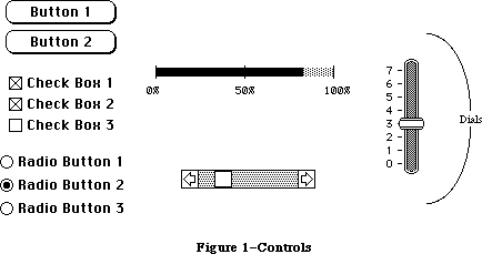 Figure 1–Controls
Note: The Control Manager doesn’t know how radio buttons are grouped,
and doesn’t automatically turn one off when the user clicks another
one on: It’s up to your program to handle this
Another important category of controls is dials. These display the value, magnitude, or position of something, typically in some pseudo-analog form such as the position of a sliding switch, the reading on a thermometer scale, or the angle of a needle on a gauge; the setting may be displayed digitally as well. The control’s moving part that displays the current setting is called the indicator. The user may be able to change a dial’s setting by dragging its indicator with the mouse, or the dial may simply display a value not under the user’s direct control (such as the amount of free space remaining on a disk).
One type of dial is predefined for you: The standard Macintosh scroll bars. Figure 2 shows the five parts of a scroll bar and the terms used by the Control Manager (and this chapter) to refer to them. Notice that the part of the scroll bar that Macintosh users know as the “scroll box” is called the “thumb” here. Also, for simplicity, the terms “up” and “down” are used even when referring to horizontal scroll bars (in which case “up” really means “left” and “down” means “right”).
Figure 1–Controls
Note: The Control Manager doesn’t know how radio buttons are grouped,
and doesn’t automatically turn one off when the user clicks another
one on: It’s up to your program to handle this
Another important category of controls is dials. These display the value, magnitude, or position of something, typically in some pseudo-analog form such as the position of a sliding switch, the reading on a thermometer scale, or the angle of a needle on a gauge; the setting may be displayed digitally as well. The control’s moving part that displays the current setting is called the indicator. The user may be able to change a dial’s setting by dragging its indicator with the mouse, or the dial may simply display a value not under the user’s direct control (such as the amount of free space remaining on a disk).
One type of dial is predefined for you: The standard Macintosh scroll bars. Figure 2 shows the five parts of a scroll bar and the terms used by the Control Manager (and this chapter) to refer to them. Notice that the part of the scroll bar that Macintosh users know as the “scroll box” is called the “thumb” here. Also, for simplicity, the terms “up” and “down” are used even when referring to horizontal scroll bars (in which case “up” really means “left” and “down” means “right”).
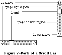 Figure 2–Parts of a Scroll Bar
The up and down arrows scroll the window’s contents a line at a time. The two paging regions scroll a “page” (windowful) at a time. The thumb can be dragged to any position in the scroll bar, to scroll to a corresponding position within the document. Although they may seem to behave like individual controls, these are all parts of a single control, the scroll bar type of dial. You can define other dials of any shape or complexity for yourself if your application needs them.
A control may be active or inactive. Active controls respond to the user’s mouse actions; inactive controls don’t. When an active control is clicked or pressed, it’s usually highlighted (see Figure 3). Standard button controls are inverted, but some control types may use other forms of highlighting, such as making the outline heavier. It’s also possible for just a part of a control to be highlighted: For example, when the user presses the mouse button inside a scroll arrow or the thumb in a scroll bar, the arrow or thumb (not the whole scroll bar) becomes highlighted until the button is released.
Figure 2–Parts of a Scroll Bar
The up and down arrows scroll the window’s contents a line at a time. The two paging regions scroll a “page” (windowful) at a time. The thumb can be dragged to any position in the scroll bar, to scroll to a corresponding position within the document. Although they may seem to behave like individual controls, these are all parts of a single control, the scroll bar type of dial. You can define other dials of any shape or complexity for yourself if your application needs them.
A control may be active or inactive. Active controls respond to the user’s mouse actions; inactive controls don’t. When an active control is clicked or pressed, it’s usually highlighted (see Figure 3). Standard button controls are inverted, but some control types may use other forms of highlighting, such as making the outline heavier. It’s also possible for just a part of a control to be highlighted: For example, when the user presses the mouse button inside a scroll arrow or the thumb in a scroll bar, the arrow or thumb (not the whole scroll bar) becomes highlighted until the button is released.
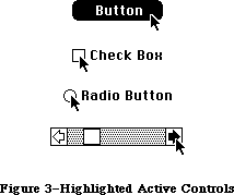 Figure 3–Highlighted Active Controls
A control is made inactive when it has no meaning or effect in the current context, such as an “Open” button when no document has been selected to open, or a scroll bar when there’s currently nothing to scroll to. An inactive control remains visible, but is highlighted in some special way, depending on its control type (see Figure 4). For example, the title of an inactive button, check box, or radio button is dimmed (drawn in gray rather than black).
Figure 3–Highlighted Active Controls
A control is made inactive when it has no meaning or effect in the current context, such as an “Open” button when no document has been selected to open, or a scroll bar when there’s currently nothing to scroll to. An inactive control remains visible, but is highlighted in some special way, depending on its control type (see Figure 4). For example, the title of an inactive button, check box, or radio button is dimmed (drawn in gray rather than black).
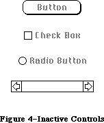 Figure 4–Inactive Controls
_______________________________________________________________________________
»CONTROLS AND WINDOWS
_______________________________________________________________________________
Every control “belongs” to a particular window: When displayed, the control appears within that window’s content region; when manipulated with the mouse, it acts on that window. All coordinates pertaining to the control (such as those describing its location) are given in its window’s local coordinate system.
Warning: In order for the Control Manager to draw a control properly, the
control’s window must have the top left corner of its grafPort’s
portRect at coordinates (0,0). If you change a window’s local
coordinate system for any reason (with the QuickDraw procedure
SetOrigin), be sure to change it back—so that the top left corner
is again at (0,0)—before drawing any of its controls. Since almost
all of the Control Manager routines can (at least potentially)
redraw a control, the safest policy is simply to change the
coordinate system back before calling any Control Manager routine.
Normally you’ll include buttons and check boxes in dialog or alert windows only. You create such windows with the Dialog Manager, and the Dialog Manager takes care of drawing the controls and letting you know whether the user clicked one of them. See the Dialog Manager chapter for details.
_______________________________________________________________________________
»CONTROLS AND RESOURCES
_______________________________________________________________________________
The relationship between controls and resources is analogous to the relationship between windows and resources: Just as there are window definition functions and window templates, there are control definition functions and control templates.
Each type of control has a control definition function that determines how controls of that type look and behave. The Control Manager calls the control definition function whenever it needs to perform a type-dependent action, such as drawing the control on the screen. Control definition functions are stored as resources and accessed through the Resource Manager. The system resource file includes definition functions for the standard control types (buttons, check boxes, radio buttons, and scroll bars). If you want to define your own, nonstandard control types, you’ll have to write control definition functions for them, as described later in the section “Defining Your Own Controls”.
When you create a control, you specify its type with a control definition ID, which tells the Control Manager the resource ID of the definition function for that control type. The Control Manager provides the following predefined constants for the definition IDs of the standard control types:
CONST pushButProc = 0; {simple button}
checkBoxProc = 1; {check box}
radioButProc = 2; {radio button}
scrollBarProc = 16; {scroll bar}
Note: The control definition function for scroll bars figures out whether
a scroll bar is vertical or horizontal from a rectangle you specify
when you create the control.
The title of a button, check box, or radio button normally appears in the system font, but you can add the following constant to the definition ID to specify that you instead want to use the font currently associated with the window’s grafPort:
CONST useWFont = 8; {use window's font}
To create a control, the Control Manager needs to know not only the control definition ID but also other information specific to this control, such as its title (if any), the window it belongs to, and its location within the window. You can supply all the needed information in individual parameters to a Control Manager routine, or you can store it in a control template in a resource file and just pass the template’s resource ID. Using templates is highly recommended, since it simplifies the process of creating controls and isolates the control descriptions from your application’s code.
_______________________________________________________________________________
»PART CODES
_______________________________________________________________________________
Some controls, such as buttons, are simple and straightforward. Others can be complex objects with many parts: For example, a scroll bar has two scroll arrows, two paging regions, and a thumb (see Figure 2 above). To allow different parts of a control to respond to the mouse in different ways, many of the Control Manager routines accept a part code as a parameter or return one as a result.
A part code is an integer between 1 and 253 that stands for a particular part of a control. Each type of control has its own set of part codes, assigned by the control definition function for that type. A simple control such as a button or check box might have just one “part” that encompasses the entire control; a more complex control such as a scroll bar can have as many parts as are needed to define how the control operates.
Note: The values 254 and 255 aren’t used for part codes—254 is reserved
for future use, and 255 means the entire control is inactive.
The part codes for the standard control types are as follows:
CONST inButton = 10; {simple button}
inCheckBox = 11; {check box or radio button}
inUpButton = 20; {up arrow of a scroll bar}
inDownButton = 21; {down arrow of a scroll bar}
inPageUp = 22; {"page up" region of a scroll bar}
inPageDown = 23; {"page down" region of a scroll bar}
inThumb = 129; {thumb of a scroll bar}
Notice that inCheckBox applies to both check boxes and radio buttons.
Note: For special information about assigning part codes to your own
control types, see “Defining Your Own Controls”.
_______________________________________________________________________________
»CONTROL RECORDS
_______________________________________________________________________________
Every control is represented internally by a control record containing all pertinent information about that control. The control record contains the following:
• A pointer to the window the control belongs to.
• A handle to the next control in the window’s control list.
• A handle to the control definition function.
• The control’s title, if any.
• A rectangle that completely encloses the control, which determines
the control’s size and location within its window. The entire control,
including the title of a check box or radio button, is drawn inside
this rectangle.
• An indication of whether the control is currently active and how it’s
to be highlighted.
• The current setting of the control (if this type of control retains a
setting) and the minimum and maximum values the setting can assume#uFor
check boxes and radio buttons, a setting of 0 means the control is off
and 1 means it’s on.
The control record also contains an indication of whether the control is currently visible or invisible. These terms refer only to whether the control is drawn in its window, not to whether you can see it on the screen. A control may be “visible” and still not appear on the screen, because it’s obscured by overlapping windows or other objects.
There’s a field in the control record for a pointer to the control’s default action procedure. An action procedure defines some action to be performed repeatedly for as long as the user holds down the mouse button inside the control. The default action procedure may be used by the Control Manager function TrackControl if you call it without passing a pointer to an action procedure; this is discussed in detail in the description of TrackControl in the “Control Manager Routines” section.
Finally, the control record includes a 32-bit reference value field, which is reserved for use by your application. You specify an initial reference value when you create a control, and can then read or change the reference value whenever you wish.
The data type for a control record is called ControlRecord. A control record is referred to by a handle:
TYPE ControlPtr = ^ControlRecord;
ControlHandle = ^ControlPtr;
The Control Manager functions for creating a control return a handle to a newly allocated control record; thereafter, your program should normally refer to the control by this handle. Most of the Control Manager routines expect a control handle as their first parameter.
You can store into and access most of a control record’s fields with Control Manager routines, so normally you don’t have to know the exact field names. However, if you want more information about the exact structure of a control record—if you’re defining your own control types, for instance—it’s given below.
_______________________________________________________________________________
»The Control Record Data Type
The ControlRecord data type is defined as follows:
TYPE ControlRecord =
PACKED RECORD
nextControl: ControlHandle; {next control}
contrlOwner: WindowPtr; {control's window}
contrlRect: Rect; {enclosing rectangle}
contrlVis: Byte; {255 if visible}
contrlHilite: Byte; {highlight state}
contrlValue: INTEGER; {control's current setting}
contrlMin: INTEGER; {control's minimum setting}
contrlMax: INTEGER; {control's maximum setting}
contrlDefProc: Handle; {control definition function}
contrlData: Handle; {data used by contrlDefProc}
contrlAction: ProcPtr; {default action procedure}
contrlRfCon: LONGINT; {control's reference value}
contrlTitle: Str255 {control's title}
END;
NextControl is a handle to the next control associated with this control’s window. All the controls belonging to a given window are kept in a linked list, beginning in the controlList field of the window record and chained together through the nextControl fields of the individual control records. The end of the list is marked by a NIL value; as new controls are created, they’re added to the beginning of the list.
ContrlOwner is a pointer to the window that this control belongs to.
ContrlRect is the rectangle that completely encloses the control, in the local coordinates of the control’s window.
When contrlVis is 0, the control is currently invisible; when it’s 255, the control is visible.
ContrlHilite specifies whether and how the control is to be highlighted, indicating whether it’s active or inactive. The HiliteControl procedure lets you set this field; see the description of HiliteControl for more information about the meaning of the field’s value.
ContrlValue is the control’s current setting. For check boxes and radio buttons, 0 means the control is off and 1 means it’s on. For dials, the fields contrlMin and contrlMax define the range of possible settings; contrlValue may take on any value within that range. Other (custom) control types can use these three fields as they see fit.
ContrlDefProc is a handle to the control definition function for this type of control. When you create a control, you identify its type with a control definition ID, which is converted into a handle to the control definition function and stored in the contrlDefProc field. Thereafter, the Control Manager uses this handle to access the definition function; you should never need to refer to this field directly.
Note: When not running in 32-bit mode, the high-order byte of the
contrlDefProc field contains some additional information that
the Control Manager gets from the control definition ID; for
details, see the section “Defining Your Own Controls”.
ContrlData is reserved for use by the control definition function, typically to hold additional information specific to a particular control type. For example, the standard definition function for scroll bars uses this field for a handle to the region containing the scroll bar’s thumb. If no more than four bytes of additional information are needed, the definition function can store the information directly in the contrlData field rather than use a handle.
ContrlAction is a pointer to the control’s default action procedure, if any. The Control Manager function TrackControl may call this procedure to respond to the user’s dragging the mouse inside the control.
ContrlRfCon is the control’s reference value field, which the application may store into and access for any purpose.
ContrlTitle is the control’s title, if any.
_______________________________________________________________________________
»AUXILIARY CONTROL RECORDS
_______________________________________________________________________________
The information needed for drawing controls in color is kept in a linked list of auxiliary control records, beginning in the global variable AuxCtlHead.
(Notice that there is just one global list for all controls in all windows, not a separate one for each window.) Each window record has a handle to the list of controls. Figure 5 shows the auxiliary control list structure.
Figure 4–Inactive Controls
_______________________________________________________________________________
»CONTROLS AND WINDOWS
_______________________________________________________________________________
Every control “belongs” to a particular window: When displayed, the control appears within that window’s content region; when manipulated with the mouse, it acts on that window. All coordinates pertaining to the control (such as those describing its location) are given in its window’s local coordinate system.
Warning: In order for the Control Manager to draw a control properly, the
control’s window must have the top left corner of its grafPort’s
portRect at coordinates (0,0). If you change a window’s local
coordinate system for any reason (with the QuickDraw procedure
SetOrigin), be sure to change it back—so that the top left corner
is again at (0,0)—before drawing any of its controls. Since almost
all of the Control Manager routines can (at least potentially)
redraw a control, the safest policy is simply to change the
coordinate system back before calling any Control Manager routine.
Normally you’ll include buttons and check boxes in dialog or alert windows only. You create such windows with the Dialog Manager, and the Dialog Manager takes care of drawing the controls and letting you know whether the user clicked one of them. See the Dialog Manager chapter for details.
_______________________________________________________________________________
»CONTROLS AND RESOURCES
_______________________________________________________________________________
The relationship between controls and resources is analogous to the relationship between windows and resources: Just as there are window definition functions and window templates, there are control definition functions and control templates.
Each type of control has a control definition function that determines how controls of that type look and behave. The Control Manager calls the control definition function whenever it needs to perform a type-dependent action, such as drawing the control on the screen. Control definition functions are stored as resources and accessed through the Resource Manager. The system resource file includes definition functions for the standard control types (buttons, check boxes, radio buttons, and scroll bars). If you want to define your own, nonstandard control types, you’ll have to write control definition functions for them, as described later in the section “Defining Your Own Controls”.
When you create a control, you specify its type with a control definition ID, which tells the Control Manager the resource ID of the definition function for that control type. The Control Manager provides the following predefined constants for the definition IDs of the standard control types:
CONST pushButProc = 0; {simple button}
checkBoxProc = 1; {check box}
radioButProc = 2; {radio button}
scrollBarProc = 16; {scroll bar}
Note: The control definition function for scroll bars figures out whether
a scroll bar is vertical or horizontal from a rectangle you specify
when you create the control.
The title of a button, check box, or radio button normally appears in the system font, but you can add the following constant to the definition ID to specify that you instead want to use the font currently associated with the window’s grafPort:
CONST useWFont = 8; {use window's font}
To create a control, the Control Manager needs to know not only the control definition ID but also other information specific to this control, such as its title (if any), the window it belongs to, and its location within the window. You can supply all the needed information in individual parameters to a Control Manager routine, or you can store it in a control template in a resource file and just pass the template’s resource ID. Using templates is highly recommended, since it simplifies the process of creating controls and isolates the control descriptions from your application’s code.
_______________________________________________________________________________
»PART CODES
_______________________________________________________________________________
Some controls, such as buttons, are simple and straightforward. Others can be complex objects with many parts: For example, a scroll bar has two scroll arrows, two paging regions, and a thumb (see Figure 2 above). To allow different parts of a control to respond to the mouse in different ways, many of the Control Manager routines accept a part code as a parameter or return one as a result.
A part code is an integer between 1 and 253 that stands for a particular part of a control. Each type of control has its own set of part codes, assigned by the control definition function for that type. A simple control such as a button or check box might have just one “part” that encompasses the entire control; a more complex control such as a scroll bar can have as many parts as are needed to define how the control operates.
Note: The values 254 and 255 aren’t used for part codes—254 is reserved
for future use, and 255 means the entire control is inactive.
The part codes for the standard control types are as follows:
CONST inButton = 10; {simple button}
inCheckBox = 11; {check box or radio button}
inUpButton = 20; {up arrow of a scroll bar}
inDownButton = 21; {down arrow of a scroll bar}
inPageUp = 22; {"page up" region of a scroll bar}
inPageDown = 23; {"page down" region of a scroll bar}
inThumb = 129; {thumb of a scroll bar}
Notice that inCheckBox applies to both check boxes and radio buttons.
Note: For special information about assigning part codes to your own
control types, see “Defining Your Own Controls”.
_______________________________________________________________________________
»CONTROL RECORDS
_______________________________________________________________________________
Every control is represented internally by a control record containing all pertinent information about that control. The control record contains the following:
• A pointer to the window the control belongs to.
• A handle to the next control in the window’s control list.
• A handle to the control definition function.
• The control’s title, if any.
• A rectangle that completely encloses the control, which determines
the control’s size and location within its window. The entire control,
including the title of a check box or radio button, is drawn inside
this rectangle.
• An indication of whether the control is currently active and how it’s
to be highlighted.
• The current setting of the control (if this type of control retains a
setting) and the minimum and maximum values the setting can assume#uFor
check boxes and radio buttons, a setting of 0 means the control is off
and 1 means it’s on.
The control record also contains an indication of whether the control is currently visible or invisible. These terms refer only to whether the control is drawn in its window, not to whether you can see it on the screen. A control may be “visible” and still not appear on the screen, because it’s obscured by overlapping windows or other objects.
There’s a field in the control record for a pointer to the control’s default action procedure. An action procedure defines some action to be performed repeatedly for as long as the user holds down the mouse button inside the control. The default action procedure may be used by the Control Manager function TrackControl if you call it without passing a pointer to an action procedure; this is discussed in detail in the description of TrackControl in the “Control Manager Routines” section.
Finally, the control record includes a 32-bit reference value field, which is reserved for use by your application. You specify an initial reference value when you create a control, and can then read or change the reference value whenever you wish.
The data type for a control record is called ControlRecord. A control record is referred to by a handle:
TYPE ControlPtr = ^ControlRecord;
ControlHandle = ^ControlPtr;
The Control Manager functions for creating a control return a handle to a newly allocated control record; thereafter, your program should normally refer to the control by this handle. Most of the Control Manager routines expect a control handle as their first parameter.
You can store into and access most of a control record’s fields with Control Manager routines, so normally you don’t have to know the exact field names. However, if you want more information about the exact structure of a control record—if you’re defining your own control types, for instance—it’s given below.
_______________________________________________________________________________
»The Control Record Data Type
The ControlRecord data type is defined as follows:
TYPE ControlRecord =
PACKED RECORD
nextControl: ControlHandle; {next control}
contrlOwner: WindowPtr; {control's window}
contrlRect: Rect; {enclosing rectangle}
contrlVis: Byte; {255 if visible}
contrlHilite: Byte; {highlight state}
contrlValue: INTEGER; {control's current setting}
contrlMin: INTEGER; {control's minimum setting}
contrlMax: INTEGER; {control's maximum setting}
contrlDefProc: Handle; {control definition function}
contrlData: Handle; {data used by contrlDefProc}
contrlAction: ProcPtr; {default action procedure}
contrlRfCon: LONGINT; {control's reference value}
contrlTitle: Str255 {control's title}
END;
NextControl is a handle to the next control associated with this control’s window. All the controls belonging to a given window are kept in a linked list, beginning in the controlList field of the window record and chained together through the nextControl fields of the individual control records. The end of the list is marked by a NIL value; as new controls are created, they’re added to the beginning of the list.
ContrlOwner is a pointer to the window that this control belongs to.
ContrlRect is the rectangle that completely encloses the control, in the local coordinates of the control’s window.
When contrlVis is 0, the control is currently invisible; when it’s 255, the control is visible.
ContrlHilite specifies whether and how the control is to be highlighted, indicating whether it’s active or inactive. The HiliteControl procedure lets you set this field; see the description of HiliteControl for more information about the meaning of the field’s value.
ContrlValue is the control’s current setting. For check boxes and radio buttons, 0 means the control is off and 1 means it’s on. For dials, the fields contrlMin and contrlMax define the range of possible settings; contrlValue may take on any value within that range. Other (custom) control types can use these three fields as they see fit.
ContrlDefProc is a handle to the control definition function for this type of control. When you create a control, you identify its type with a control definition ID, which is converted into a handle to the control definition function and stored in the contrlDefProc field. Thereafter, the Control Manager uses this handle to access the definition function; you should never need to refer to this field directly.
Note: When not running in 32-bit mode, the high-order byte of the
contrlDefProc field contains some additional information that
the Control Manager gets from the control definition ID; for
details, see the section “Defining Your Own Controls”.
ContrlData is reserved for use by the control definition function, typically to hold additional information specific to a particular control type. For example, the standard definition function for scroll bars uses this field for a handle to the region containing the scroll bar’s thumb. If no more than four bytes of additional information are needed, the definition function can store the information directly in the contrlData field rather than use a handle.
ContrlAction is a pointer to the control’s default action procedure, if any. The Control Manager function TrackControl may call this procedure to respond to the user’s dragging the mouse inside the control.
ContrlRfCon is the control’s reference value field, which the application may store into and access for any purpose.
ContrlTitle is the control’s title, if any.
_______________________________________________________________________________
»AUXILIARY CONTROL RECORDS
_______________________________________________________________________________
The information needed for drawing controls in color is kept in a linked list of auxiliary control records, beginning in the global variable AuxCtlHead.
(Notice that there is just one global list for all controls in all windows, not a separate one for each window.) Each window record has a handle to the list of controls. Figure 5 shows the auxiliary control list structure.
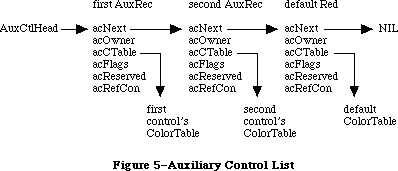 Figure 5–Auxiliary Control List
Each auxiliary control record is a relocatable object residing in the application heap. The most important information it holds is a handle to the control’s individual color table (see the “Control Color Tables” section). The rest of the record consists of a link to the next record in the list, a field that identifies the control’s owner, a 4-byte field reserved for future expansion, and a 4-byte reference constant for use by the application:
TYPE
AuxCtlHandle = ^AuxCtlPtr;
AuxCtlPtr = ^AuxCtlRec;
AuxCtlRec = RECORD
acNext: AuxCtlHandle; {handle to next record in list}
acOwner: ControlHandle; {handle to owning control}
acCTable: CCTabHandle; {handle to control's color }
{ table}
acFlags: INTEGER; {miscellaneous flags; reserved}
acReserved: LONGINT; {reserved for future expansion}
acRefCon: LONGINT {reserved for application use}
END;
Field descriptions
acNext The acNext field contains a handle to the next record in
the auxiliary control list.
acOwner The acOwner field contains the handle of the control to
which this auxiliary record belongs. Used as an ID field.
acCTable The acCTable contains the handle to the control’s color
table (see “Control Color Tables” below).
acFlags The acFlags field contains miscellaneous flags for use by
the Control Manager; this field is reserved.
acReserved The acReserved field is reserved for future expansion;
this must be set to 0 for future compatibility.
acRefCon The acRefCon field is a reference constant for use by
the application.
Not every control needs an auxiliary control record. When an application is started, a resource containing a default color table is loaded from the system resource file; this resource defines a standard set of control colors. Since there is no InitControls routine, this happens when an application calls InitWindows.
Separate auxiliary control records are needed only for controls whose color usage differs from the default. Each such nonstandard control must have its own auxiliary record, even if it uses the same colors as another control. This allows two or more auxiliary records to share the same control color table. If the control color table is a resource, it won’t be deleted by DisposeControl. When using an auxiliary record that is not stored as a resource, the application should not deallocate the color table if another control is still using it.
A control created from scratch will initially have no auxiliary control record. If it is to use nonstandard colors, it must be given an auxiliary record and a color table with SetCtlColor (see the “Control Manager Routines” section). Such a control should normally be made invisible at creation and then displayed with ShowControl after the colors are set. For controls created from a 'CNTL' resource, the color table can be specified as a resource as well. See the section titled “The Control Color Table Resource”.
A/UX systems: When using 32-bit mode. every control has its own auxiliary
record. If there is no specific set of control colors for
this control, the acCTable will point to the default color table.
_______________________________________________________________________________
»CONTROL COLOR TABLES
_______________________________________________________________________________
The contents and meaning of a control’s color table are determined by its control definition function (see “The Control Color Table Resource” section). The CTabHandle parameter used in the Color Control Manager routines provides a handle to the control color table. The components of a control color table are defined as follows:
TYPE
CCTabHandle = ^CCTabPtr;
CCTabPtr = ^CtlCTab;
CtlCTab = RECORD
ccSeed: LONGINT; {not used for controls}
ccRider: INTEGER; {not used for controls}
ctSize: INTEGER; {number of entries in table –1}
ctTable: cSpecArray {array of ColorSpec records}
END;
Field descriptions
ccSeed The ccSeed field is unused in control color tables.
ccRider The ccRider field is unused in control color tables.
ctSize The ctSize field defines the number of elements in the table,
minus one. For controls drawn with the standard definition
procedure, this field is always 3.
ctTable The ctTable field holds an array of colorSpec records. Each
colorSpec is made up of a partIdentifier field and a partRGB
field. The partIdentifier field holds an integer which
associates an RGBColor to a particular part of the control.
The definition procedures attempt to find the appropriate part
identifier when preparing to draw a part. If that part
identifier is not found, the first color in the table is
used to draw the part. The part identifiers can appear in any
order in the table. The partRGB field specifies a standard RGB
color record, indicating what absolute color will be used to
draw the control part found in the partIdentifier field.
A standard control color table is shown in Figure 6.
Figure 5–Auxiliary Control List
Each auxiliary control record is a relocatable object residing in the application heap. The most important information it holds is a handle to the control’s individual color table (see the “Control Color Tables” section). The rest of the record consists of a link to the next record in the list, a field that identifies the control’s owner, a 4-byte field reserved for future expansion, and a 4-byte reference constant for use by the application:
TYPE
AuxCtlHandle = ^AuxCtlPtr;
AuxCtlPtr = ^AuxCtlRec;
AuxCtlRec = RECORD
acNext: AuxCtlHandle; {handle to next record in list}
acOwner: ControlHandle; {handle to owning control}
acCTable: CCTabHandle; {handle to control's color }
{ table}
acFlags: INTEGER; {miscellaneous flags; reserved}
acReserved: LONGINT; {reserved for future expansion}
acRefCon: LONGINT {reserved for application use}
END;
Field descriptions
acNext The acNext field contains a handle to the next record in
the auxiliary control list.
acOwner The acOwner field contains the handle of the control to
which this auxiliary record belongs. Used as an ID field.
acCTable The acCTable contains the handle to the control’s color
table (see “Control Color Tables” below).
acFlags The acFlags field contains miscellaneous flags for use by
the Control Manager; this field is reserved.
acReserved The acReserved field is reserved for future expansion;
this must be set to 0 for future compatibility.
acRefCon The acRefCon field is a reference constant for use by
the application.
Not every control needs an auxiliary control record. When an application is started, a resource containing a default color table is loaded from the system resource file; this resource defines a standard set of control colors. Since there is no InitControls routine, this happens when an application calls InitWindows.
Separate auxiliary control records are needed only for controls whose color usage differs from the default. Each such nonstandard control must have its own auxiliary record, even if it uses the same colors as another control. This allows two or more auxiliary records to share the same control color table. If the control color table is a resource, it won’t be deleted by DisposeControl. When using an auxiliary record that is not stored as a resource, the application should not deallocate the color table if another control is still using it.
A control created from scratch will initially have no auxiliary control record. If it is to use nonstandard colors, it must be given an auxiliary record and a color table with SetCtlColor (see the “Control Manager Routines” section). Such a control should normally be made invisible at creation and then displayed with ShowControl after the colors are set. For controls created from a 'CNTL' resource, the color table can be specified as a resource as well. See the section titled “The Control Color Table Resource”.
A/UX systems: When using 32-bit mode. every control has its own auxiliary
record. If there is no specific set of control colors for
this control, the acCTable will point to the default color table.
_______________________________________________________________________________
»CONTROL COLOR TABLES
_______________________________________________________________________________
The contents and meaning of a control’s color table are determined by its control definition function (see “The Control Color Table Resource” section). The CTabHandle parameter used in the Color Control Manager routines provides a handle to the control color table. The components of a control color table are defined as follows:
TYPE
CCTabHandle = ^CCTabPtr;
CCTabPtr = ^CtlCTab;
CtlCTab = RECORD
ccSeed: LONGINT; {not used for controls}
ccRider: INTEGER; {not used for controls}
ctSize: INTEGER; {number of entries in table –1}
ctTable: cSpecArray {array of ColorSpec records}
END;
Field descriptions
ccSeed The ccSeed field is unused in control color tables.
ccRider The ccRider field is unused in control color tables.
ctSize The ctSize field defines the number of elements in the table,
minus one. For controls drawn with the standard definition
procedure, this field is always 3.
ctTable The ctTable field holds an array of colorSpec records. Each
colorSpec is made up of a partIdentifier field and a partRGB
field. The partIdentifier field holds an integer which
associates an RGBColor to a particular part of the control.
The definition procedures attempt to find the appropriate part
identifier when preparing to draw a part. If that part
identifier is not found, the first color in the table is
used to draw the part. The part identifiers can appear in any
order in the table. The partRGB field specifies a standard RGB
color record, indicating what absolute color will be used to
draw the control part found in the partIdentifier field.
A standard control color table is shown in Figure 6.
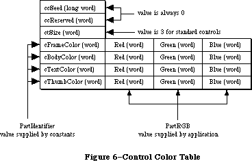 Figure 6–Control Color Table
The 'cctb' resource is an exact image of this control table data structure, and is stored in the same format as 'clut' color table resources.
Standard buttons, check boxes, and radio buttons use a four-element color table with part identifiers as shown below:
cFrameColor (0) Frame color
cBodyColor (1) Fill color for body of control
cTextColor (2) Text color
cThumbColor (3) Unused
When highlighted, plain buttons exchange their body and text colors (colors 1 and 2); check boxes and radio buttons change their appearance without changing colors. All three types indicate deactivation by dimming their text with no change in colors.
Standard scroll bars use a four-element color table with part identifiers as shown below:
cFrameColor (0) Frame color, foreground color for shaft and arrows
cBodyColor (1 Background color for shaft and arrows
cTextColor (2) Unused
cThumbColor (3) Fill color for thumb
When highlighted, the arrows are filled with the foreground color (color 0) within the arrow outline. A deactivated scroll bar shows no indicator, and displays its shaft in solid background color (color 1), with no pattern.
The 'cctb' resource = 0 is read into the application heap when the application starts, and serves as the default control color table. The last record in the auxiliary control list points to the default 'cctb' resource. When drawing a control, the standard control definition function searches the list for an auxiliary control record whose acOwner points to the control being drawn. If it finds such a record, it uses the color table designated by that record; if it doesn’t find one before reaching the default record at the end of the list, it uses the default color table instead. All types of controls share the same default record. The default auxiliary control record is recognized by NIL values in both its acNext and acOwner fields; the application must not change these fields.
A nonstandard control definition function can use color tables of any desired size and define their contents in any way it wishes, except that part indices 1 to 127 are reserved for system definition. Any such nonstandard function should take care to bypass the defaulting mechanism just described, by allocating an explicit auxiliary record for every control it creates.
_______________________________________________________________________________
»THE CONTROL COLOR TABLE RESOURCE
_______________________________________________________________________________
The system default control colors are stored in the System file and ROMResources as 'cctb' resource = 0. By including a 'cctb' resource = 0 in your application, it is possible to change the default colors that will be used for all controls, unless a specific 'cctb' exists for a control defined within the application.
When you use GetNewControl for the control resource 'CNTL', GetNewControl will attempt to load a 'cctb' resource with the same ID as the 'CNTL' resource ID, if one is present. It then executes the SetCtlColor call.
The following part identifiers for control elements should be present in the ColorSpec.value field:
cFrameColor (0) Frame color
cBodyColor (1) Fill color for body of control
cTextColor (2) Text color
cThumbColor (3) Thumb color
These identifiers may be present in any order; for instance, the text or indicator color values may be stored before the fill and frame colors in the ColorSpec record structure. If a part identifier is not found, then the first color in the color table will be used.
_______________________________________________________________________________
»USING THE CONTROL MANAGER
_______________________________________________________________________________
To use the Control Manager, you must have previously called InitGraf to initialize QuickDraw, InitFonts to initialize the Font Manager, and InitWindows to initialize the Window Manager.
Note: For controls in dialogs or alerts, the Dialog Manager makes some
of the basic Control Manager calls for you; see the Dialog Manager
chapter for more information.
Where appropriate in your program, use NewControl or GetNewControl to create any controls you need. NewControl takes descriptive information about the new control from its parameters; GetNewControl gets the information from a control template in a resource file. When you no longer need a control, call DisposeControl to remove it from its window’s control list and release the memory it occupies. To dispose of all of a given window’s controls at once, use KillControls.
Note: The Window Manager procedures DisposeWindow and CloseWindow
automatically dispose of all the controls associated with the
given window.
When the Toolbox Event Manager function GetNextEvent reports that an update event has occurred for a window, the application should call DrawControls to redraw the window’s controls as part of the process of updating the window.
After receiving a mouse-down event from GetNextEvent, do the following:
1. First call FindWindow to determine which part of which window the
mouse button was pressed in.
2. If it was in the content region of the active window, call FindControl
for that window to find out whether it was in an active control, and
if so, in which part of which control.
3. Finally, take whatever action is appropriate when the user presses
the mouse button in that part of the control, using routines such
as TrackControl (to perform some action repeatedly for as long as
the mouse button is down, or to allow the user to drag the control’s
indicator with the mouse), DragControl (to pull an outline of the
control across the screen and move the control to a new location),
and HiliteControl (to change the way the control is highlighted).
For the standard control types, step 3 involves calling TrackControl. TrackControl handles the highlighting of the control and determines whether the mouse is still in the control when the mouse button is released. It also handles the dragging of the thumb in a scroll bar and, via your action procedure, the response to presses or clicks in the other parts of a scroll bar. When TrackControl returns the part code for a button, check box, or radio button, the application must do whatever is appropriate as a response to a click of that control. When TrackControl returns the part code for the thumb of a scroll bar, the application must scroll to the corresponding relative position in the document.
The application’s exact response to mouse activity in a control that retains a setting will depend on the current setting of the control, which is available from the GetCtlValue function. For controls whose values can be set by the user, the SetCtlValue procedure may be called to change the control’s setting and redraw the control accordingly. You’ll call SetCtlValue, for example, when a check box or radio button is clicked, to change the setting and draw or clear the mark inside the control.
Wherever needed in your program, you can call HideControl to make a control invisible or ShowControl to make it visible. Similarly, MoveControl, which simply changes a control’s location without pulling around an outline of it, can be called at any time, as can SizeControl, which changes its size. For example, when the user changes the size of a document window that contains a scroll bar, you’ll call HideControl to remove the old scroll bar, MoveControl and SizeControl to change its location and size, and ShowControl to display it as changed.
Whenever necessary, you can read various attributes of a control with GetCTitle, GetCtlMin, GetCtlMax, GetCRefCon, or GetCtlAction; you can change them with SetCTitle, SetCtlMin, SetCtlMax, SetCRefCon, or SetCtlAction.
_______________________________________________________________________________
»USING COLOR CONTROLS
_______________________________________________________________________________
The following caveats apply to the use of color with controls:
• Controls are drawn in the window port, which by default is an
old-style GrafPort. This limits color matching to the eight old
QuickDraw colors. To achieve full RGB display with controls, the
window must be opened as a cGrafPort, using NewCWindow, GetNewCWindow,
or any other window routine that creates a color window.
Since there is no “InitControls” call, a default AuxCtlRec is created and intialized on the application heap when InitWindows is executed. When a new control is created with the NewControl routine, no entry is added to the AuxList, and the control will use the default colors. If SetCtlColor is used with a different color set of a control, a new AuxList will be allocated and added to the head of the list. The CloseControl routine disposes of the AuxCtlRec.
Often a new control is created from a 'CNTL' resource, using GetNewControl. A new AuxRec is allocated if the resource file contains a 'cctb' resource type with the same resource ID as the 'CNTL' resource. Otherwise, the default colors are used.
The Control Manager supports controls that have color tables with more than four elements. To create a control with more than four colors, you must create a custom 'CDEF' that can access a larger color table.The interpretation of the partIdentifiers is determined by the 'CDEF'. If your application includes a
'CDEF' that recognizes more than four partIdentifiers, it should use partIdentifiers 0–3 in the same way as the standard control defprocs. An application with a custom 'CDEF" should use the _SysEnvirons routine upon entry to the defproc to determine the configuration of the system.
_______________________________________________________________________________
»CONTROL MANAGER ROUTINES
_______________________________________________________________________________
»Initialization and Allocation
FUNCTION NewControl (theWindow: WindowPtr; boundsRect: Rect; title: Str255;
visible: BOOLEAN; value: INTEGER; min,max: INTEGER;
procID: INTEGER; refCon: LONGINT) : ControlHandle;
NewControl creates a control, adds it to the beginning of theWindow’s control list, and returns a handle to the new control. The values passed as parameters are stored in the corresponding fields of the control record, as described below. The field that determines highlighting is set to 0 (no highlighting) and the pointer to the default action procedure is set to NIL (none).
Note: The control definition function may do additional initialization,
including changing any of the fields of the control record. The only
standard control for which additional initialization is done is the
scroll bar; its control definition function allocates space for a
region to hold the thumb and stores the region handle in the
contrlData field of the control record.
TheWindow is the window the new control will belong to. All coordinates pertaining to the control will be interpreted in this window’s local coordinate system.
BoundsRect, given in theWindow’s local coordinates, is the rectangle that encloses the control and thus determines its size and location. Note the following about the enclosing rectangle for the standard controls:
• Simple buttons are drawn to fit the rectangle exactly. (The control
definition function calls the QuickDraw procedure FrameRoundRect.) To
allow for the tallest characters in the system font, there should be
at least a 20-point difference between the top and bottom coordinates
of the rectangle.
• For check boxes and radio buttons, there should be at least a 16-point
difference between the top and bottom coordinates.
• By convention, scroll bars are 16 pixels wide, so there should be a
16-point difference between the left and right (or top and bottom)
coordinates. (If there isn’t, the scroll bar will be scaled to fit
the rectangle.) A standard scroll bar should be at least 48 pixels
long, to allow room for the scroll arrows and thumb.
Title is the control’s title, if any (if none, you can just pass the empty string as the title). Be sure the title will fit in the control’s enclosing rectangle; if it won’t it will be truncated on the right for check boxes and radio buttons, or centered and truncated on both ends for simple buttons.
Note: Some non-Roman systems write text from right-to-left, in which
case radio buttons and check boxes are drawn with their titles
on the left of the control. They are also truncated on the left.
See the Script Manager chapter for more information.
If the visible parameter is TRUE, NewControl draws the control.
Note: It does not use the standard window updating mechanism, but
instead draws the control immediately in the window.
The min and max parameters define the control’s range of possible settings; the value parameter gives the initial setting. For controls that don’t retain a setting, such as buttons, the values you supply for these parameters will be stored in the control record but will never be used. So it doesn’t matter what values you give for those controls—0 for all three parameters will do. For controls that just retain an on-or-off setting, such as check boxes or radio buttons, min should be 0 (meaning the control is off) and max should be 1
(meaning it’s on). For dials, you can specify whatever values are appropriate for min, max, and value.
ProcID is the control definition ID, which leads to the control definition function for this type of control. (The function is read into memory if it
isn’t already in memory.) The control definition IDs for the standard control types are listed above under “Controls and Resources”. Control definition IDs for custom control types are discussed later under “Defining Your Own Controls”.
RefCon is the control’s reference value, set and used only by your application.
FUNCTION GetNewControl (controlID: INTEGER;
theWindow: WindowPtr) : ControlHandle;
GetNewControl creates a control from a control template stored in a resource file, adds it to the beginning of theWindow’s control list, and returns a handle to the new control. ControlID is the resource ID of the template. GetNewControl works exactly the same as NewControl (above), except that it gets the initial values for the new control’s fields from the specified control template instead of accepting them as parameters. If the control template can’t be read from the resource file, GetNewControl returns NIL. It releases the memory occupied by the resource before returning.
PROCEDURE DisposeControl (theControl: ControlHandle);
Assembly-language note: The macro you invoke to call DisposeControl from
assembly language is named _DisposControl.
DisposeControl removes theControl from the screen, deletes it from its window’s control list, and releases the memory occupied by the control record and any data structures associated with the control.
PROCEDURE KillControls (theWindow: WindowPtr);
KillControls disposes of all controls associated with theWindow by calling DisposeControl (above) for each.
Note: Remember that the Window Manager procedures CloseWindow and
DisposeWindow automatically dispose of all controls associated
with the given window.
_______________________________________________________________________________
»Control Display
These procedures affect the appearance of a control but not its size or location.
PROCEDURE SetCTitle (theControl: ControlHandle; title: Str255);
SetCTitle sets theControl’s title to the given string and redraws the control.
PROCEDURE GetCTitle (theControl: ControlHandle; VAR title: Str255);
GetCTitle returns theControl’s title as the value of the title parameter.
PROCEDURE HideControl (theControl: ControlHandle);
HideControl makes theControl invisible. It fills the region the control occupies within its window with the background pattern of the window’s grafPort. It also adds the control’s enclosing rectangle to the window’s update region, so that anything else that was previously obscured by the control will reappear on the screen. If the control is already invisible, HideControl has no effect.
PROCEDURE ShowControl (theControl: ControlHandle);
ShowControl makes theControl visible. The control is drawn in its window but may be completely or partially obscured by overlapping windows or other objects. If the control is already visible, ShowControl has no effect.
PROCEDURE DrawControls (theWindow: WindowPtr);
DrawControls draws all controls currently visible in theWindow. The controls are drawn in reverse order of creation; thus in case of overlap the earliest-created controls appear frontmost in the window.
Note: Window Manager routines such as SelectWindow, ShowWindow, and
BringToFront do not automatically call DrawControls to display
the window’s controls. They just add the appropriate regions to
the window’s update region, generating an update event. Your program
should always call DrawControls explicitly upon receiving an update
event for a window that contains controls.
PROCEDURE Draw1Control (theControl: ControlHandle); [128K ROM]
Draw1Control draws the specified control if it’s visible within the window.
PROCEDURE UpdtControl (theWindow: WindowPtr; updateRgn: RgnHandle); [128K ROM]
UpdtControl is a faster version of the DrawControls procedure. Instead of drawing all of the controls in theWindow, UpdtControl draws only the controls that are in the specified update region. UpdtControl is called in response to an update event, and is usually bracketed by calls to the Window Manager procedures BeginUpdate and EndUpdate. UpdateRgn should be set to the visRgn of theWindow’s port (for more details, see the BeginUpdate procedure in the Window Manager chapter).
Note: In general, controls are in a dialog box and are automatically
drawn by the DrawDialog procedure.
PROCEDURE HiliteControl (theControl: ControlHandle; hiliteState: INTEGER);
HiliteControl changes the way theControl is highlighted. HiliteState has one of the following values:
• The value 0 means no highlighting. (The control is active.)
• A value between 1 and 253 is interpreted as a part code designating
the part of the (active) control to be highlighted.
• The value 255 means that the control is to be made inactive and
highlighted accordingly.
Note: The value 254 should not be used; this value is reserved for future use.
HiliteControl calls the control definition function to redraw the control with its new highlighting.
_______________________________________________________________________________
»Mouse Location
FUNCTION FindControl (thePoint: Point; theWindow: WindowPtr; VAR whichControl: ControlHandle) : INTEGER;
When the Window Manager function FindWindow reports that the mouse button was pressed in the content region of a window, and the window contains controls, the application should call FindControl with theWindow equal to the window pointer and thePoint equal to the point where the mouse button was pressed (in the window’s local coordinates). FindControl tells which of the window’s controls, if any, the mouse button was pressed in:
• If it was pressed in a visible, active control, FindControl sets the
whichControl parameter to the control handle and returns a part code
identifying the part of the control that it was pressed in.
• If it was pressed in an invisible or inactive control, or not in any
control, FindControl sets whichControl to NIL and returns 0 as its result.
Warning: Notice that FindControl expects the mouse point in the window’s
local coordinates, whereas FindWindow expects it in global
coordinates. Always be sure to convert the point to local
coordinates with the QuickDraw procedure GlobalToLocal before
calling FindControl.
Note: FindControl also returns NIL for whichControl and 0 as its result
if the window is invisible or doesn’t contain the given point. In
these cases, however, FindWindow wouldn’t have returned this window
in the first place, so the situation should never arise.
FUNCTION TrackControl (theControl: ControlHandle; startPt: Point;
actionProc: ProcPtr) : INTEGER;
When the mouse button is pressed in a visible, active control, the application should call TrackControl with theControl equal to the control handle and startPt equal to the point where the mouse button was pressed (in the local coordinates of the control’s window). TrackControl follows the movements of the mouse and responds in whatever way is appropriate until the mouse button is released; the exact response depends on the type of control and the part of the control in which the mouse button was pressed. If highlighting is appropriate, TrackControl does the highlighting, and undoes it before returning. When the mouse button is released, TrackControl returns with the part code if the mouse is in the same part of the control that it was originally in, or with 0 if not
(in which case the application should do nothing).
If the mouse button was pressed in an indicator, TrackControl drags a dotted outline of it to follow the mouse. When the mouse button is released, TrackControl calls the control definition function to reposition the control’s indicator. The control definition function for scroll bars responds by redrawing the thumb, calculating the control’s current setting based on the new relative position of the thumb, and storing the current setting in the control record; for example, if the minimum and maximum settings are 0 and 10, and the thumb is in the middle of the scroll bar, 5 is stored as the current setting. The application must then scroll to the corresponding relative position in the document.
TrackControl may take additional actions beyond highlighting the control or dragging the indicator, depending on the value passed in the actionProc parameter, as described below. The following tells you what to pass for the standard control types; for a custom control, what you pass will depend on how the control is defined.
• If actionProc is NIL, TrackControl performs no additional actions. This
is appropriate for simple buttons, check boxes, radio buttons, and the
thumb of a scroll bar.
• ActionProc may be a pointer to an action procedure that defines some
action to be performed repeatedly for as long as the user holds down
the mouse button. (See below for details.)
• If actionProc is POINTER(–1), TrackControl looks in the control record
for a pointer to the control’s default action procedure. If that field
of the control record contains a procedure pointer, TrackControl uses
the action procedure it points to; if the field contains POINTER (–1),
TrackControl calls the control definition function to perform the
necessary action. (If the field contains NIL, TrackControl does nothing.)
The action procedure in the control definition function is described in the section “Defining Your Own Controls”. The following paragraphs describe only the action procedure whose pointer is passed in the actionProc parameter or stored in the control record.
If the mouse button was pressed in an indicator, the action procedure (if any) should have no parameters. This procedure must allow for the fact that the mouse may not be inside the original control part.
If the mouse button was pressed in a control part other than an indicator, the action procedure should be of the form
PROCEDURE MyAction (theControl: ControlHandle; partCode: INTEGER);
In this case, TrackControl passes the control handle and the part code to the action procedure. (It passes 0 in the partCode parameter if the mouse has moved outside the original control part.) As an example of this type of action procedure, consider what should happen when the mouse button is pressed in a scroll arrow or paging region in a scroll bar. For these cases, your action procedure should examine the part code to determine exactly where the mouse button was pressed, scroll up or down a line or page as appropriate, and call SetCtlValue to change the control’s setting and redraw the thumb.
Warning: Since it has a different number of parameters depending on whether
the mouse button was pressed in an indicator or elsewhere, the
action procedure you pass to TrackControl (or whose pointer you
store in the control record) can be set up for only one case or
the other. If you store a pointer to a default action procedure
in a control record, be sure it will be used only when appropriate
for that type of action procedure. The only way to specify actions
in response to all mouse-down events in a control, regardless of
whether they’re in an indicator, is via the control definition
function.
Assembly-language note: If you store a pointer to a procedure in the global
variable DragHook, that procedure will be called
repeatedly (with no parameters) for as long as the
user holds down the mouse button. TrackControl
invokes the Window Manager macro _DragTheRgn,
which calls the DragHook procedure. _DragTheRgn
uses the pattern stored in the global variable
DragPattern for the dragged outline of the indicator.
FUNCTION TestControl (theControl: ControlHandle; thePoint: Point) : INTEGER;
If theControl is visible and active, TestControl tests which part of the control contains thePoint (in the local coordinates of the control’s window); it returns the corresponding part code, or 0 if the point is outside the control. If the control is invisible or inactive, TestControl returns 0. TestControl is called by FindControl and TrackControl; normally you won’t need to call it yourself.
_______________________________________________________________________________
»Control Movement and Sizing
PROCEDURE MoveControl (theControl: ControlHandle; h,v: INTEGER);
MoveControl moves theControl to a new location within its window. The top left corner of the control’s enclosing rectangle is moved to the horizontal and vertical coordinates h and v (given in the local coordinates of the control’s window); the bottom right corner is adjusted accordingly, to keep the size of the rectangle the same as before. If the control is currently visible, it’s hidden and then redrawn at its new location.
PROCEDURE DragControl (theControl: ControlHandle; startPt: Point;
limitRect,slopRect: Rect; axis: INTEGER);
Called with the mouse button down inside theControl, DragControl pulls a dotted outline of the control around the screen, following the movements of the mouse until the button is released. When the mouse button is released, DragControl calls MoveControl to move the control to the location to which it was dragged.
Note: Before beginning to follow the mouse, DragControl calls the control
definition function to allow it to do its own “custom dragging” if
it chooses. If the definition function doesn’t choose to do any
custom dragging, DragControl uses the default method of dragging
described here.
The startPt, limitRect, slopRect, and axis parameters have the same meaning as for the Window Manager function DragGrayRgn. These parameters are reviewed briefly below; see the description of DragGrayRgn in the Window Manager chapter for more details.
• StartPt is assumed to be the point where the mouse button was originally
pressed, in the local coordinates of the control’s window.
• LimitRect limits the travel of the control’s outline, and should normally
coincide with or be contained within the window’s content region.
• SlopRect allows the user some “slop” in moving the mouse; it should
completely enclose limitRect.
• The axis parameter allows you to constrain the control’s motion to
only one axis. It has one of the following values:
CONST noConstraint = 0; {no constraint}
hAxisOnly = 1; {horizontal axis only}
vAxisOnly = 2; {vertical axis only}
Assembly-language note: Like TrackControl, DragControl invokes the
macro _DragTheRgn, so you can use the global
variables DragHook and DragPattern.
PROCEDURE SizeControl (theControl: ControlHandle; w,h: INTEGER);
SizeControl changes the size of theControl’s enclosing rectangle. The bottom right corner of the rectangle is adjusted to set the rectangle’s width and height to the number of pixels specified by w and h; the position of the top left corner is not changed. If the control is currently visible, it’s hidden and then redrawn in its new size.
_______________________________________________________________________________
»Control Setting and Range
PROCEDURE SetCtlValue (theControl: ControlHandle; theValue: INTEGER);
SetCtlValue sets theControl’s current setting to theValue and redraws the control to reflect the new setting. For check boxes and radio buttons, the value 1 fills the control with the appropriate mark, and 0 clears it. For scroll bars, SetCtlValue redraws the thumb where appropriate.
If the specified value is out of range, it’s forced to the nearest endpoint of the current range (that is, if theValue is less than the minimum setting, SetCtlValue sets the current setting to the minimum; if theValue is greater than the maximum setting, it sets the current setting to the maximum).
FUNCTION GetCtlValue (theControl: ControlHandle) : INTEGER;
GetCtlValue returns theControl’s current setting.
PROCEDURE SetCtlMin (theControl: ControlHandle; minValue: INTEGER);
Assembly-language note: The macro you invoke to call SetCtlMin from
assembly language is named _SetMinCtl.
SetCtlMin sets theControl’s minimum setting to minValue and redraws the control to reflect the new range. If the control’s current setting is less than minValue, the setting is changed to the new minimum.
FUNCTION GetCtlMin (theControl: ControlHandle) : INTEGER;
Assembly-language note: The macro you invoke to call GetCtlMin from
assembly language is named _GetMinCtl.
GetCtlMin returns theControl’s minimum setting.
PROCEDURE SetCtlMax (theControl: ControlHandle; maxValue: INTEGER);
Assembly-language note: The macro you invoke to call SetCtlMax from
assembly language is named _SetMaxCtl.
SetCtlMax sets theControl’s maximum setting to maxValue and redraws the control to reflect the new range. If the control’s current setting is greater than maxValue, the setting is changed to the new maximum.
Note: If you set the maximum setting of a scroll bar equal to its minimum
setting, the control definition function will make the scroll bar
inactive.
FUNCTION GetCtlMax (theControl: ControlHandle) : INTEGER;
Assembly-language note: The macro you invoke to call GetCtlMax from
assembly language is named _GetMaxCtl.
GetCtlMax returns theControl’s maximum setting.
_______________________________________________________________________________
»Miscellaneous Routines
PROCEDURE SetCRefCon (theControl: ControlHandle; data: LONGINT);
SetCRefCon sets theControl’s reference value to the given data.
FUNCTION GetCRefCon (theControl: ControlHandle) : LONGINT;
GetCRefCon returns theControl’s current reference value.
PROCEDURE SetCtlAction (theControl: ControlHandle; actionProc: ProcPtr);
SetCtlAction sets theControl’s default action procedure to actionProc.
FUNCTION GetCtlAction (theControl: ControlHandle) : ProcPtr;
GetCtlAction returns a pointer to theControl’s default action procedure, if any. (It returns whatever is in that field of the control record.)
The following new Control Manager routines can be used as noted below for the Macintosh Plus, the Macintosh SE, and the Macintosh II.
FUNCTION GetCVariant (theControl: ControlHandle) : INTEGER;
[Macintosh Plus, Macintosh SE, and Macintosh II]
The GetVariant function returns the variant control value for the control described by theControl. This value was formerly stored in the high four bits of the control defproc handle; for future compatibility, use the GetCVariant routine to access this value.
PROCEDURE SetCtlColor (theControl: ControlHandle; newColorTable: CCTabHandle);
[Macintosh II]
The SetCtlColor procedure sets or modifies a control’s color table. If the control currently has no auxiliary control record, a new one is created with the given color table and added to the head of the auxiliary control list. If there is already an auxiliary record for the control, its color table is replaced by the contents of newColorTable.
If newColorTable has the same contents as the default color table, the
control’s existing auxiliary record and color table are removed from the auxiliary control list and deallocated. If theControl = NIL, the operation modifies the default color table itself. If the control is visible, it will be redrawn by SetCtlColor using the new color table.
FUNCTION GetAuxCtl (theControl: ControlHandle;
VAR acHndl: AuxCtlHandle) : BOOLEAN; [Macintosh II]
The GetAuxCtl function returns a handle to a control’s AuxCtlRec:
• If the given control has its own color table, the function returns TRUE.
• If the control used the default color set, the function returns FALSE.
• If the control asked to receive the default color set (theControl = NIL),
then the function returns TRUE.
_______________________________________________________________________________
»DEFINING YOUR OWN CONTROLS
_______________________________________________________________________________
In addition to the standard, built-in control types (buttons, check boxes, radio buttons, and scroll bars), the Control Manager allows you to define
“custom” control types of your own. Maybe you need a three-way selector switch, a memory-space indicator that looks like a thermometer, or a thruster control for a spacecraft simulator—whatever your application calls for. Controls and their indicators may occupy regions of any shape, in the full generality permitted by QuickDraw.
To define your own type of control, you write a control definition function and store it in a resource file. When you create a control, you provide a control definition ID, which leads to the control definition function. The control definition ID is an integer that contains the resource ID of the control definition function in its upper 12 bits and a variation code in its lower four bits. Thus, for a given resource ID and variation code, the control definition ID is
16 * resource ID + variation code
For example, buttons, check boxes, and radio buttons all use the standard definition function whose resource ID is 0, but they have variation codes of 0, 1, and 2, respectively.
The Control Manager calls the Resource Manager to access the control definition function with the given resource ID. The Resource Manager reads the control definition function into memory and returns a handle to it. The Control Manager stores this handle in the contrlDefProc field of the control record. In 24-bit addressing mode, the variation code is placed in the high-order byte of this field; in 32-bit mode, the variation code is placed in the most significant byte of the acReserved field in the control’s AuxCtlRec. Later, when it needs to perform a type-dependent action on the control, it calls the control definition function and passes it the variation code as a parameter. Figure 7 illustrates this process.
Keep in mind that the calls your application makes to use a control depend heavily on the control definition function. What you pass to the TrackControl function, for example, depends on whether the definition function contains an action procedure for the control. Just as you need to know how to call TrackControl for the standard controls, each custom control type will have a particular calling protocol that must be followed for the control to work properly.
_______________________________________________________________________________
»The Control Definition Function
The control definition function is usually written in assembly language, but may be written in Pascal.
Figure 6–Control Color Table
The 'cctb' resource is an exact image of this control table data structure, and is stored in the same format as 'clut' color table resources.
Standard buttons, check boxes, and radio buttons use a four-element color table with part identifiers as shown below:
cFrameColor (0) Frame color
cBodyColor (1) Fill color for body of control
cTextColor (2) Text color
cThumbColor (3) Unused
When highlighted, plain buttons exchange their body and text colors (colors 1 and 2); check boxes and radio buttons change their appearance without changing colors. All three types indicate deactivation by dimming their text with no change in colors.
Standard scroll bars use a four-element color table with part identifiers as shown below:
cFrameColor (0) Frame color, foreground color for shaft and arrows
cBodyColor (1 Background color for shaft and arrows
cTextColor (2) Unused
cThumbColor (3) Fill color for thumb
When highlighted, the arrows are filled with the foreground color (color 0) within the arrow outline. A deactivated scroll bar shows no indicator, and displays its shaft in solid background color (color 1), with no pattern.
The 'cctb' resource = 0 is read into the application heap when the application starts, and serves as the default control color table. The last record in the auxiliary control list points to the default 'cctb' resource. When drawing a control, the standard control definition function searches the list for an auxiliary control record whose acOwner points to the control being drawn. If it finds such a record, it uses the color table designated by that record; if it doesn’t find one before reaching the default record at the end of the list, it uses the default color table instead. All types of controls share the same default record. The default auxiliary control record is recognized by NIL values in both its acNext and acOwner fields; the application must not change these fields.
A nonstandard control definition function can use color tables of any desired size and define their contents in any way it wishes, except that part indices 1 to 127 are reserved for system definition. Any such nonstandard function should take care to bypass the defaulting mechanism just described, by allocating an explicit auxiliary record for every control it creates.
_______________________________________________________________________________
»THE CONTROL COLOR TABLE RESOURCE
_______________________________________________________________________________
The system default control colors are stored in the System file and ROMResources as 'cctb' resource = 0. By including a 'cctb' resource = 0 in your application, it is possible to change the default colors that will be used for all controls, unless a specific 'cctb' exists for a control defined within the application.
When you use GetNewControl for the control resource 'CNTL', GetNewControl will attempt to load a 'cctb' resource with the same ID as the 'CNTL' resource ID, if one is present. It then executes the SetCtlColor call.
The following part identifiers for control elements should be present in the ColorSpec.value field:
cFrameColor (0) Frame color
cBodyColor (1) Fill color for body of control
cTextColor (2) Text color
cThumbColor (3) Thumb color
These identifiers may be present in any order; for instance, the text or indicator color values may be stored before the fill and frame colors in the ColorSpec record structure. If a part identifier is not found, then the first color in the color table will be used.
_______________________________________________________________________________
»USING THE CONTROL MANAGER
_______________________________________________________________________________
To use the Control Manager, you must have previously called InitGraf to initialize QuickDraw, InitFonts to initialize the Font Manager, and InitWindows to initialize the Window Manager.
Note: For controls in dialogs or alerts, the Dialog Manager makes some
of the basic Control Manager calls for you; see the Dialog Manager
chapter for more information.
Where appropriate in your program, use NewControl or GetNewControl to create any controls you need. NewControl takes descriptive information about the new control from its parameters; GetNewControl gets the information from a control template in a resource file. When you no longer need a control, call DisposeControl to remove it from its window’s control list and release the memory it occupies. To dispose of all of a given window’s controls at once, use KillControls.
Note: The Window Manager procedures DisposeWindow and CloseWindow
automatically dispose of all the controls associated with the
given window.
When the Toolbox Event Manager function GetNextEvent reports that an update event has occurred for a window, the application should call DrawControls to redraw the window’s controls as part of the process of updating the window.
After receiving a mouse-down event from GetNextEvent, do the following:
1. First call FindWindow to determine which part of which window the
mouse button was pressed in.
2. If it was in the content region of the active window, call FindControl
for that window to find out whether it was in an active control, and
if so, in which part of which control.
3. Finally, take whatever action is appropriate when the user presses
the mouse button in that part of the control, using routines such
as TrackControl (to perform some action repeatedly for as long as
the mouse button is down, or to allow the user to drag the control’s
indicator with the mouse), DragControl (to pull an outline of the
control across the screen and move the control to a new location),
and HiliteControl (to change the way the control is highlighted).
For the standard control types, step 3 involves calling TrackControl. TrackControl handles the highlighting of the control and determines whether the mouse is still in the control when the mouse button is released. It also handles the dragging of the thumb in a scroll bar and, via your action procedure, the response to presses or clicks in the other parts of a scroll bar. When TrackControl returns the part code for a button, check box, or radio button, the application must do whatever is appropriate as a response to a click of that control. When TrackControl returns the part code for the thumb of a scroll bar, the application must scroll to the corresponding relative position in the document.
The application’s exact response to mouse activity in a control that retains a setting will depend on the current setting of the control, which is available from the GetCtlValue function. For controls whose values can be set by the user, the SetCtlValue procedure may be called to change the control’s setting and redraw the control accordingly. You’ll call SetCtlValue, for example, when a check box or radio button is clicked, to change the setting and draw or clear the mark inside the control.
Wherever needed in your program, you can call HideControl to make a control invisible or ShowControl to make it visible. Similarly, MoveControl, which simply changes a control’s location without pulling around an outline of it, can be called at any time, as can SizeControl, which changes its size. For example, when the user changes the size of a document window that contains a scroll bar, you’ll call HideControl to remove the old scroll bar, MoveControl and SizeControl to change its location and size, and ShowControl to display it as changed.
Whenever necessary, you can read various attributes of a control with GetCTitle, GetCtlMin, GetCtlMax, GetCRefCon, or GetCtlAction; you can change them with SetCTitle, SetCtlMin, SetCtlMax, SetCRefCon, or SetCtlAction.
_______________________________________________________________________________
»USING COLOR CONTROLS
_______________________________________________________________________________
The following caveats apply to the use of color with controls:
• Controls are drawn in the window port, which by default is an
old-style GrafPort. This limits color matching to the eight old
QuickDraw colors. To achieve full RGB display with controls, the
window must be opened as a cGrafPort, using NewCWindow, GetNewCWindow,
or any other window routine that creates a color window.
Since there is no “InitControls” call, a default AuxCtlRec is created and intialized on the application heap when InitWindows is executed. When a new control is created with the NewControl routine, no entry is added to the AuxList, and the control will use the default colors. If SetCtlColor is used with a different color set of a control, a new AuxList will be allocated and added to the head of the list. The CloseControl routine disposes of the AuxCtlRec.
Often a new control is created from a 'CNTL' resource, using GetNewControl. A new AuxRec is allocated if the resource file contains a 'cctb' resource type with the same resource ID as the 'CNTL' resource. Otherwise, the default colors are used.
The Control Manager supports controls that have color tables with more than four elements. To create a control with more than four colors, you must create a custom 'CDEF' that can access a larger color table.The interpretation of the partIdentifiers is determined by the 'CDEF'. If your application includes a
'CDEF' that recognizes more than four partIdentifiers, it should use partIdentifiers 0–3 in the same way as the standard control defprocs. An application with a custom 'CDEF" should use the _SysEnvirons routine upon entry to the defproc to determine the configuration of the system.
_______________________________________________________________________________
»CONTROL MANAGER ROUTINES
_______________________________________________________________________________
»Initialization and Allocation
FUNCTION NewControl (theWindow: WindowPtr; boundsRect: Rect; title: Str255;
visible: BOOLEAN; value: INTEGER; min,max: INTEGER;
procID: INTEGER; refCon: LONGINT) : ControlHandle;
NewControl creates a control, adds it to the beginning of theWindow’s control list, and returns a handle to the new control. The values passed as parameters are stored in the corresponding fields of the control record, as described below. The field that determines highlighting is set to 0 (no highlighting) and the pointer to the default action procedure is set to NIL (none).
Note: The control definition function may do additional initialization,
including changing any of the fields of the control record. The only
standard control for which additional initialization is done is the
scroll bar; its control definition function allocates space for a
region to hold the thumb and stores the region handle in the
contrlData field of the control record.
TheWindow is the window the new control will belong to. All coordinates pertaining to the control will be interpreted in this window’s local coordinate system.
BoundsRect, given in theWindow’s local coordinates, is the rectangle that encloses the control and thus determines its size and location. Note the following about the enclosing rectangle for the standard controls:
• Simple buttons are drawn to fit the rectangle exactly. (The control
definition function calls the QuickDraw procedure FrameRoundRect.) To
allow for the tallest characters in the system font, there should be
at least a 20-point difference between the top and bottom coordinates
of the rectangle.
• For check boxes and radio buttons, there should be at least a 16-point
difference between the top and bottom coordinates.
• By convention, scroll bars are 16 pixels wide, so there should be a
16-point difference between the left and right (or top and bottom)
coordinates. (If there isn’t, the scroll bar will be scaled to fit
the rectangle.) A standard scroll bar should be at least 48 pixels
long, to allow room for the scroll arrows and thumb.
Title is the control’s title, if any (if none, you can just pass the empty string as the title). Be sure the title will fit in the control’s enclosing rectangle; if it won’t it will be truncated on the right for check boxes and radio buttons, or centered and truncated on both ends for simple buttons.
Note: Some non-Roman systems write text from right-to-left, in which
case radio buttons and check boxes are drawn with their titles
on the left of the control. They are also truncated on the left.
See the Script Manager chapter for more information.
If the visible parameter is TRUE, NewControl draws the control.
Note: It does not use the standard window updating mechanism, but
instead draws the control immediately in the window.
The min and max parameters define the control’s range of possible settings; the value parameter gives the initial setting. For controls that don’t retain a setting, such as buttons, the values you supply for these parameters will be stored in the control record but will never be used. So it doesn’t matter what values you give for those controls—0 for all three parameters will do. For controls that just retain an on-or-off setting, such as check boxes or radio buttons, min should be 0 (meaning the control is off) and max should be 1
(meaning it’s on). For dials, you can specify whatever values are appropriate for min, max, and value.
ProcID is the control definition ID, which leads to the control definition function for this type of control. (The function is read into memory if it
isn’t already in memory.) The control definition IDs for the standard control types are listed above under “Controls and Resources”. Control definition IDs for custom control types are discussed later under “Defining Your Own Controls”.
RefCon is the control’s reference value, set and used only by your application.
FUNCTION GetNewControl (controlID: INTEGER;
theWindow: WindowPtr) : ControlHandle;
GetNewControl creates a control from a control template stored in a resource file, adds it to the beginning of theWindow’s control list, and returns a handle to the new control. ControlID is the resource ID of the template. GetNewControl works exactly the same as NewControl (above), except that it gets the initial values for the new control’s fields from the specified control template instead of accepting them as parameters. If the control template can’t be read from the resource file, GetNewControl returns NIL. It releases the memory occupied by the resource before returning.
PROCEDURE DisposeControl (theControl: ControlHandle);
Assembly-language note: The macro you invoke to call DisposeControl from
assembly language is named _DisposControl.
DisposeControl removes theControl from the screen, deletes it from its window’s control list, and releases the memory occupied by the control record and any data structures associated with the control.
PROCEDURE KillControls (theWindow: WindowPtr);
KillControls disposes of all controls associated with theWindow by calling DisposeControl (above) for each.
Note: Remember that the Window Manager procedures CloseWindow and
DisposeWindow automatically dispose of all controls associated
with the given window.
_______________________________________________________________________________
»Control Display
These procedures affect the appearance of a control but not its size or location.
PROCEDURE SetCTitle (theControl: ControlHandle; title: Str255);
SetCTitle sets theControl’s title to the given string and redraws the control.
PROCEDURE GetCTitle (theControl: ControlHandle; VAR title: Str255);
GetCTitle returns theControl’s title as the value of the title parameter.
PROCEDURE HideControl (theControl: ControlHandle);
HideControl makes theControl invisible. It fills the region the control occupies within its window with the background pattern of the window’s grafPort. It also adds the control’s enclosing rectangle to the window’s update region, so that anything else that was previously obscured by the control will reappear on the screen. If the control is already invisible, HideControl has no effect.
PROCEDURE ShowControl (theControl: ControlHandle);
ShowControl makes theControl visible. The control is drawn in its window but may be completely or partially obscured by overlapping windows or other objects. If the control is already visible, ShowControl has no effect.
PROCEDURE DrawControls (theWindow: WindowPtr);
DrawControls draws all controls currently visible in theWindow. The controls are drawn in reverse order of creation; thus in case of overlap the earliest-created controls appear frontmost in the window.
Note: Window Manager routines such as SelectWindow, ShowWindow, and
BringToFront do not automatically call DrawControls to display
the window’s controls. They just add the appropriate regions to
the window’s update region, generating an update event. Your program
should always call DrawControls explicitly upon receiving an update
event for a window that contains controls.
PROCEDURE Draw1Control (theControl: ControlHandle); [128K ROM]
Draw1Control draws the specified control if it’s visible within the window.
PROCEDURE UpdtControl (theWindow: WindowPtr; updateRgn: RgnHandle); [128K ROM]
UpdtControl is a faster version of the DrawControls procedure. Instead of drawing all of the controls in theWindow, UpdtControl draws only the controls that are in the specified update region. UpdtControl is called in response to an update event, and is usually bracketed by calls to the Window Manager procedures BeginUpdate and EndUpdate. UpdateRgn should be set to the visRgn of theWindow’s port (for more details, see the BeginUpdate procedure in the Window Manager chapter).
Note: In general, controls are in a dialog box and are automatically
drawn by the DrawDialog procedure.
PROCEDURE HiliteControl (theControl: ControlHandle; hiliteState: INTEGER);
HiliteControl changes the way theControl is highlighted. HiliteState has one of the following values:
• The value 0 means no highlighting. (The control is active.)
• A value between 1 and 253 is interpreted as a part code designating
the part of the (active) control to be highlighted.
• The value 255 means that the control is to be made inactive and
highlighted accordingly.
Note: The value 254 should not be used; this value is reserved for future use.
HiliteControl calls the control definition function to redraw the control with its new highlighting.
_______________________________________________________________________________
»Mouse Location
FUNCTION FindControl (thePoint: Point; theWindow: WindowPtr; VAR whichControl: ControlHandle) : INTEGER;
When the Window Manager function FindWindow reports that the mouse button was pressed in the content region of a window, and the window contains controls, the application should call FindControl with theWindow equal to the window pointer and thePoint equal to the point where the mouse button was pressed (in the window’s local coordinates). FindControl tells which of the window’s controls, if any, the mouse button was pressed in:
• If it was pressed in a visible, active control, FindControl sets the
whichControl parameter to the control handle and returns a part code
identifying the part of the control that it was pressed in.
• If it was pressed in an invisible or inactive control, or not in any
control, FindControl sets whichControl to NIL and returns 0 as its result.
Warning: Notice that FindControl expects the mouse point in the window’s
local coordinates, whereas FindWindow expects it in global
coordinates. Always be sure to convert the point to local
coordinates with the QuickDraw procedure GlobalToLocal before
calling FindControl.
Note: FindControl also returns NIL for whichControl and 0 as its result
if the window is invisible or doesn’t contain the given point. In
these cases, however, FindWindow wouldn’t have returned this window
in the first place, so the situation should never arise.
FUNCTION TrackControl (theControl: ControlHandle; startPt: Point;
actionProc: ProcPtr) : INTEGER;
When the mouse button is pressed in a visible, active control, the application should call TrackControl with theControl equal to the control handle and startPt equal to the point where the mouse button was pressed (in the local coordinates of the control’s window). TrackControl follows the movements of the mouse and responds in whatever way is appropriate until the mouse button is released; the exact response depends on the type of control and the part of the control in which the mouse button was pressed. If highlighting is appropriate, TrackControl does the highlighting, and undoes it before returning. When the mouse button is released, TrackControl returns with the part code if the mouse is in the same part of the control that it was originally in, or with 0 if not
(in which case the application should do nothing).
If the mouse button was pressed in an indicator, TrackControl drags a dotted outline of it to follow the mouse. When the mouse button is released, TrackControl calls the control definition function to reposition the control’s indicator. The control definition function for scroll bars responds by redrawing the thumb, calculating the control’s current setting based on the new relative position of the thumb, and storing the current setting in the control record; for example, if the minimum and maximum settings are 0 and 10, and the thumb is in the middle of the scroll bar, 5 is stored as the current setting. The application must then scroll to the corresponding relative position in the document.
TrackControl may take additional actions beyond highlighting the control or dragging the indicator, depending on the value passed in the actionProc parameter, as described below. The following tells you what to pass for the standard control types; for a custom control, what you pass will depend on how the control is defined.
• If actionProc is NIL, TrackControl performs no additional actions. This
is appropriate for simple buttons, check boxes, radio buttons, and the
thumb of a scroll bar.
• ActionProc may be a pointer to an action procedure that defines some
action to be performed repeatedly for as long as the user holds down
the mouse button. (See below for details.)
• If actionProc is POINTER(–1), TrackControl looks in the control record
for a pointer to the control’s default action procedure. If that field
of the control record contains a procedure pointer, TrackControl uses
the action procedure it points to; if the field contains POINTER (–1),
TrackControl calls the control definition function to perform the
necessary action. (If the field contains NIL, TrackControl does nothing.)
The action procedure in the control definition function is described in the section “Defining Your Own Controls”. The following paragraphs describe only the action procedure whose pointer is passed in the actionProc parameter or stored in the control record.
If the mouse button was pressed in an indicator, the action procedure (if any) should have no parameters. This procedure must allow for the fact that the mouse may not be inside the original control part.
If the mouse button was pressed in a control part other than an indicator, the action procedure should be of the form
PROCEDURE MyAction (theControl: ControlHandle; partCode: INTEGER);
In this case, TrackControl passes the control handle and the part code to the action procedure. (It passes 0 in the partCode parameter if the mouse has moved outside the original control part.) As an example of this type of action procedure, consider what should happen when the mouse button is pressed in a scroll arrow or paging region in a scroll bar. For these cases, your action procedure should examine the part code to determine exactly where the mouse button was pressed, scroll up or down a line or page as appropriate, and call SetCtlValue to change the control’s setting and redraw the thumb.
Warning: Since it has a different number of parameters depending on whether
the mouse button was pressed in an indicator or elsewhere, the
action procedure you pass to TrackControl (or whose pointer you
store in the control record) can be set up for only one case or
the other. If you store a pointer to a default action procedure
in a control record, be sure it will be used only when appropriate
for that type of action procedure. The only way to specify actions
in response to all mouse-down events in a control, regardless of
whether they’re in an indicator, is via the control definition
function.
Assembly-language note: If you store a pointer to a procedure in the global
variable DragHook, that procedure will be called
repeatedly (with no parameters) for as long as the
user holds down the mouse button. TrackControl
invokes the Window Manager macro _DragTheRgn,
which calls the DragHook procedure. _DragTheRgn
uses the pattern stored in the global variable
DragPattern for the dragged outline of the indicator.
FUNCTION TestControl (theControl: ControlHandle; thePoint: Point) : INTEGER;
If theControl is visible and active, TestControl tests which part of the control contains thePoint (in the local coordinates of the control’s window); it returns the corresponding part code, or 0 if the point is outside the control. If the control is invisible or inactive, TestControl returns 0. TestControl is called by FindControl and TrackControl; normally you won’t need to call it yourself.
_______________________________________________________________________________
»Control Movement and Sizing
PROCEDURE MoveControl (theControl: ControlHandle; h,v: INTEGER);
MoveControl moves theControl to a new location within its window. The top left corner of the control’s enclosing rectangle is moved to the horizontal and vertical coordinates h and v (given in the local coordinates of the control’s window); the bottom right corner is adjusted accordingly, to keep the size of the rectangle the same as before. If the control is currently visible, it’s hidden and then redrawn at its new location.
PROCEDURE DragControl (theControl: ControlHandle; startPt: Point;
limitRect,slopRect: Rect; axis: INTEGER);
Called with the mouse button down inside theControl, DragControl pulls a dotted outline of the control around the screen, following the movements of the mouse until the button is released. When the mouse button is released, DragControl calls MoveControl to move the control to the location to which it was dragged.
Note: Before beginning to follow the mouse, DragControl calls the control
definition function to allow it to do its own “custom dragging” if
it chooses. If the definition function doesn’t choose to do any
custom dragging, DragControl uses the default method of dragging
described here.
The startPt, limitRect, slopRect, and axis parameters have the same meaning as for the Window Manager function DragGrayRgn. These parameters are reviewed briefly below; see the description of DragGrayRgn in the Window Manager chapter for more details.
• StartPt is assumed to be the point where the mouse button was originally
pressed, in the local coordinates of the control’s window.
• LimitRect limits the travel of the control’s outline, and should normally
coincide with or be contained within the window’s content region.
• SlopRect allows the user some “slop” in moving the mouse; it should
completely enclose limitRect.
• The axis parameter allows you to constrain the control’s motion to
only one axis. It has one of the following values:
CONST noConstraint = 0; {no constraint}
hAxisOnly = 1; {horizontal axis only}
vAxisOnly = 2; {vertical axis only}
Assembly-language note: Like TrackControl, DragControl invokes the
macro _DragTheRgn, so you can use the global
variables DragHook and DragPattern.
PROCEDURE SizeControl (theControl: ControlHandle; w,h: INTEGER);
SizeControl changes the size of theControl’s enclosing rectangle. The bottom right corner of the rectangle is adjusted to set the rectangle’s width and height to the number of pixels specified by w and h; the position of the top left corner is not changed. If the control is currently visible, it’s hidden and then redrawn in its new size.
_______________________________________________________________________________
»Control Setting and Range
PROCEDURE SetCtlValue (theControl: ControlHandle; theValue: INTEGER);
SetCtlValue sets theControl’s current setting to theValue and redraws the control to reflect the new setting. For check boxes and radio buttons, the value 1 fills the control with the appropriate mark, and 0 clears it. For scroll bars, SetCtlValue redraws the thumb where appropriate.
If the specified value is out of range, it’s forced to the nearest endpoint of the current range (that is, if theValue is less than the minimum setting, SetCtlValue sets the current setting to the minimum; if theValue is greater than the maximum setting, it sets the current setting to the maximum).
FUNCTION GetCtlValue (theControl: ControlHandle) : INTEGER;
GetCtlValue returns theControl’s current setting.
PROCEDURE SetCtlMin (theControl: ControlHandle; minValue: INTEGER);
Assembly-language note: The macro you invoke to call SetCtlMin from
assembly language is named _SetMinCtl.
SetCtlMin sets theControl’s minimum setting to minValue and redraws the control to reflect the new range. If the control’s current setting is less than minValue, the setting is changed to the new minimum.
FUNCTION GetCtlMin (theControl: ControlHandle) : INTEGER;
Assembly-language note: The macro you invoke to call GetCtlMin from
assembly language is named _GetMinCtl.
GetCtlMin returns theControl’s minimum setting.
PROCEDURE SetCtlMax (theControl: ControlHandle; maxValue: INTEGER);
Assembly-language note: The macro you invoke to call SetCtlMax from
assembly language is named _SetMaxCtl.
SetCtlMax sets theControl’s maximum setting to maxValue and redraws the control to reflect the new range. If the control’s current setting is greater than maxValue, the setting is changed to the new maximum.
Note: If you set the maximum setting of a scroll bar equal to its minimum
setting, the control definition function will make the scroll bar
inactive.
FUNCTION GetCtlMax (theControl: ControlHandle) : INTEGER;
Assembly-language note: The macro you invoke to call GetCtlMax from
assembly language is named _GetMaxCtl.
GetCtlMax returns theControl’s maximum setting.
_______________________________________________________________________________
»Miscellaneous Routines
PROCEDURE SetCRefCon (theControl: ControlHandle; data: LONGINT);
SetCRefCon sets theControl’s reference value to the given data.
FUNCTION GetCRefCon (theControl: ControlHandle) : LONGINT;
GetCRefCon returns theControl’s current reference value.
PROCEDURE SetCtlAction (theControl: ControlHandle; actionProc: ProcPtr);
SetCtlAction sets theControl’s default action procedure to actionProc.
FUNCTION GetCtlAction (theControl: ControlHandle) : ProcPtr;
GetCtlAction returns a pointer to theControl’s default action procedure, if any. (It returns whatever is in that field of the control record.)
The following new Control Manager routines can be used as noted below for the Macintosh Plus, the Macintosh SE, and the Macintosh II.
FUNCTION GetCVariant (theControl: ControlHandle) : INTEGER;
[Macintosh Plus, Macintosh SE, and Macintosh II]
The GetVariant function returns the variant control value for the control described by theControl. This value was formerly stored in the high four bits of the control defproc handle; for future compatibility, use the GetCVariant routine to access this value.
PROCEDURE SetCtlColor (theControl: ControlHandle; newColorTable: CCTabHandle);
[Macintosh II]
The SetCtlColor procedure sets or modifies a control’s color table. If the control currently has no auxiliary control record, a new one is created with the given color table and added to the head of the auxiliary control list. If there is already an auxiliary record for the control, its color table is replaced by the contents of newColorTable.
If newColorTable has the same contents as the default color table, the
control’s existing auxiliary record and color table are removed from the auxiliary control list and deallocated. If theControl = NIL, the operation modifies the default color table itself. If the control is visible, it will be redrawn by SetCtlColor using the new color table.
FUNCTION GetAuxCtl (theControl: ControlHandle;
VAR acHndl: AuxCtlHandle) : BOOLEAN; [Macintosh II]
The GetAuxCtl function returns a handle to a control’s AuxCtlRec:
• If the given control has its own color table, the function returns TRUE.
• If the control used the default color set, the function returns FALSE.
• If the control asked to receive the default color set (theControl = NIL),
then the function returns TRUE.
_______________________________________________________________________________
»DEFINING YOUR OWN CONTROLS
_______________________________________________________________________________
In addition to the standard, built-in control types (buttons, check boxes, radio buttons, and scroll bars), the Control Manager allows you to define
“custom” control types of your own. Maybe you need a three-way selector switch, a memory-space indicator that looks like a thermometer, or a thruster control for a spacecraft simulator—whatever your application calls for. Controls and their indicators may occupy regions of any shape, in the full generality permitted by QuickDraw.
To define your own type of control, you write a control definition function and store it in a resource file. When you create a control, you provide a control definition ID, which leads to the control definition function. The control definition ID is an integer that contains the resource ID of the control definition function in its upper 12 bits and a variation code in its lower four bits. Thus, for a given resource ID and variation code, the control definition ID is
16 * resource ID + variation code
For example, buttons, check boxes, and radio buttons all use the standard definition function whose resource ID is 0, but they have variation codes of 0, 1, and 2, respectively.
The Control Manager calls the Resource Manager to access the control definition function with the given resource ID. The Resource Manager reads the control definition function into memory and returns a handle to it. The Control Manager stores this handle in the contrlDefProc field of the control record. In 24-bit addressing mode, the variation code is placed in the high-order byte of this field; in 32-bit mode, the variation code is placed in the most significant byte of the acReserved field in the control’s AuxCtlRec. Later, when it needs to perform a type-dependent action on the control, it calls the control definition function and passes it the variation code as a parameter. Figure 7 illustrates this process.
Keep in mind that the calls your application makes to use a control depend heavily on the control definition function. What you pass to the TrackControl function, for example, depends on whether the definition function contains an action procedure for the control. Just as you need to know how to call TrackControl for the standard controls, each custom control type will have a particular calling protocol that must be followed for the control to work properly.
_______________________________________________________________________________
»The Control Definition Function
The control definition function is usually written in assembly language, but may be written in Pascal.
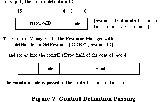 Figure 7–Control Definition Handling
Assembly-language note: The function’s entry point must be at the beginning.
You can give your control definition function any name you like. Here’s how you would declare one named MyControl:
FUNCTION MyControl (varCode: INTEGER; theControl: ControlHandle;
message: INTEGER; param: LONGINT) : LONGINT;
VarCode is the variation code, as described above.
TheControl is a handle to the control that the operation will affect.
The message parameter identifies the desired operation. It has one of the following values:
CONST drawCntl = 0; {draw the control (or control part)}
testCntl = 1; {test where mouse button was pressed}
calcCRgns = 2; {calculate control's region (or indicator's)}
initCntl = 3; {do any additional control initialization}
dispCntl = 4; {take any additional disposal actions}
posCntl = 5; {reposition control's indicator and update it}
thumbCntl = 6; {calculate parameters for dragging indicator}
dragCntl = 7; {drag control (or its indicator)}
autoTrack = 8; {execute control's action procedure}
As described below in the discussions of the routines that perform these operations, the value passed for param, the last parameter of the control definition function, depends on the operation. Where it’s not mentioned below, this parameter is ignored. Similarly, the control definition function is expected to return a function result only where indicated; in other cases, the function should return 0.
In some cases, the value of param or the function result is a part code. The part code 128 is reserved for future use and shouldn’t be used for parts of your controls. Part codes greater than 128 should be used for indicators; however, 129 has special meaning to the control definition function, as described below.
Note: “Routine” here doesn’t necessarily mean a procedure or function.
While it’s a good idea to set these up as subprograms inside the
control definition function, you’re not required to do so.
A new version of the control definition function (version 4 or greater) in the 128K ROM allows buttons, check boxes, and radio buttons to have multiple lines of text in their titles. When specifying the title with either NewControl or SetCTitle, simply separate the lines with the ASCII character code $0D
(carriage return). You can also use a version of the Resource Editor that supports the 128K ROM to specify multiline titles.
Note: This feature will work with the 64K ROM if the new version of
the control definition function is in the system resource file.
If the control is a button, each line is horizontally centered and separated from the neighboring lines by the font’s leading. (Since the height of each line is equal to the ascent plus descent plus leading of the font used, be sure to make the total height of the enclosing rectangle greater than the number of lines times this height.)
If the control is a check box or a radio button, the text is left-justified and the check box or button is vertically centered within the enclosing rectangle, cntrlRect.
Note: The text is right-justified on check boxes and radio buttons if
running under a non-Roman system that draws text from right-to-left.
See the Script Manager chapter for more information.
_______________________________________________________________________________
»The Draw Routine
The message drawCntl asks the control definition function to draw all or part of the control within its enclosing rectangle. The value of param is a part code specifying which part of the control to draw, or 0 for the entire control. If the control is invisible (that is, if its contrlVis field is 0), there’s nothing to do; if it’s visible, the definition function should draw it (or the requested part), taking into account the current values of its contrlHilite and contrlValue fields. The control may be either scaled or clipped to the enclosing rectangle.
If param is the part code of the control’s indicator, the draw routine can assume that the indicator hasn’t moved; it might be called, for example, to highlight the indicator. There’s a special case, though, in which the draw routine has to allow for the fact that the indicator may have moved: This happens when the Control Manager procedures SetCtlValue, SetCtlMin, and SetCtlMax call the control definition function to redraw the indicator after changing the control setting. Since they have no way of knowing what part code you chose for your indicator, they all pass 129 to mean the indicator. The draw routine must detect this part code as a special case, and remove the indicator from its former location before drawing it.
Note: If your control has more than one indicator, 129 should be
interpreted to mean all indicators.
_______________________________________________________________________________
»The Test Routine
The Control Manager function FindControl sends the message testCntl to the control definition function when the mouse button is pressed in a visible control. This message asks in which part of the control, if any, a given point lies. The point is passed as the value of param, in the local coordinates of the control’s window; the vertical coordinate is in the high-order word of the long integer and the horizontal coordinate is in the low-order word. The control definition function should return the part code for the part of the control that contains the point; it should return 0 if the point is outside the control or if the control is inactive.
_______________________________________________________________________________
»The Routine to Calculate Regions
The control definition function should respond to the message calcCRgns by calculating the region the control occupies within its window. Param is a QuickDraw region handle; the definition function should update this region to the region occupied by the control, expressed in the local coordinate system of its window.
If the high-order bit of param is set, the region requested is that of the control’s indicator rather than the control as a whole. The definition function should clear the high bit of the region handle before attempting to update the region.
_______________________________________________________________________________
»The Initialize Routine
After initializing fields as appropriate when creating a new control, the Control Manager sends the message initCntl to the control definition function. This gives the definition function a chance to perform any type-specific initialization it may require. For example, if you implement the control’s action procedure in its control definition function, you’ll set up the initialize routine to store POINTER(–1) in the contrlAction field; TrackControl calls for this control would pass POINTER(–1) in the actionProc parameter.
The control definition function for scroll bars allocates space for a region to hold the scroll bar’s thumb and stores the region handle in the contrlData field of the new control record. The initialize routine for standard buttons, check boxes, and radio buttons does nothing.
_______________________________________________________________________________
»The Dispose Routine
The Control Manager’s DisposeControl procedure sends the message dispCntl to the control definition function, telling it to carry out any additional actions required when disposing of the control. For example, the standard definition function for scroll bars releases the space occupied by the thumb region, whose handle is kept in the control’s contrlData field. The dispose routine for standard buttons, check boxes, and radio buttons does nothing.
_______________________________________________________________________________
»The Drag Routine
The message dragCntl asks the control definition function to drag the control or its indicator around on the screen to follow the mouse until the user releases the mouse button. Param specifies whether to drag the indicator or the whole control: 0 means drag the whole control, while a nonzero value means drag only the indicator.
The control definition function need not implement any form of “custom
dragging”; if it returns a result of 0, the Control Manager will use its own default method of dragging (calling DragControl to drag the control or the Window Manager function DragGrayRgn to drag its indicator). Conversely, if the control definition function chooses to do its own custom dragging, it should signal the Control Manager not to use the default method by returning a nonzero result.
If the whole control is being dragged, the definition function should call MoveControl to reposition the control to its new location after the user releases the mouse button. If just the indicator is being dragged, the definition function should execute its own position routine (see below) to update the control’s setting and redraw it in its window.
_______________________________________________________________________________
»The Position Routine
For controls that don’t use the Control Manager’s default method of dragging the control’s indicator (as performed by DragGrayRgn), the control definition function must include a position routine. When the mouse button is released inside the indicator of such a control, TrackControl calls the control definition function with the message posCntl to reposition the indicator and update the control’s setting accordingly. The value of param is a point giving the vertical and horizontal offset, in pixels, by which the indicator is to be moved relative to its current position. (Typically, this is the offset between the points where the user pressed and released the mouse button while dragging the indicator.) The vertical offset is given in the high-order word of the long integer and the horizontal offset in the low-order word. The definition function should calculate the control’s new setting based on the given offset, update the contrlValue field, and redraw the control within its window to reflect the new setting.
Note: The Control Manager procedures SetCtlValue, SetCtlMin, and SetCtlMax
do not call the control definition function with this message; instead,
they pass the drawCntl message to execute the draw routine (see above).
_______________________________________________________________________________
»The Thumb Routine
Like the position routine, the thumb routine is required only for controls that don’t use the Control Manager’s default method of dragging the control’s indicator. The control definition function for such a control should respond to the message thumbCntl by calculating the limiting rectangle, slop rectangle, and axis constraint for dragging the control’s indicator. Param is a pointer to the following data structure:
RECORD
limitRect,slopRect: Rect;
axis: INTEGER
END;
On entry, param^.limitRect.topLeft contains the point where the mouse button was first pressed. The definition function should store the appropriate values into the fields of the record pointed to by param; they’re analogous to the similarly named parameters to DragGrayRgn.
_______________________________________________________________________________
»The Track Routine
You can design a control to have its action procedure in the control definition function. To do this, set up the control’s initialize routine to store
POINTER(–1) in the contrlAction field of the control record, and pass
POINTER(–1) in the actionProc parameter to TrackControl. TrackControl will respond by calling the control definition function with the message autoTrack. The definition function should respond like an action procedure, as discussed in detail in the description of TrackControl. It can tell which part of the control the mouse button was pressed in from param, which contains the part code. The track routine for each of the standard control types does nothing.
_______________________________________________________________________________
»FORMATS OF RESOURCES FOR CONTROLS
_______________________________________________________________________________
The GetNewControl function takes the resource ID of a control template as a parameter, and gets from that template the same information that the NewControl function gets from eight of its parameters. The resource type for a control template is 'CNTL', and the resource data has the following format:
Number of bytes Contents
8 bytes Same as boundsRect parameter to NewControl
2 bytes Same as value parameter to NewControl
2 bytes Same as visible parameter to NewControl
2 bytes Same as max parameter to NewControl
2 bytes Same as min parameter to NewControl
2 bytes Same as procID parameter to NewControl
4 bytes Same as refCon parameter to NewControl
n bytes Same as title parameter to NewControl
(1-byte length in bytes, followed by the
characters of the title)
The resource type for a control definition function is 'CDEF'. The resource data is simply the compiled or assembled code of the function.
_______________________________________________________________________________
»SUMMARY OF THE CONTROL MANAGER
_______________________________________________________________________________
Constants
CONST
{ Control definition IDs }
pushButProc = 0; {simple button}
checkBoxProc = 1; {check box}
radioButProc = 2; {radio button}
useWFont = 8; {add to above to use window's font}
scrollBarProc = 16; {scroll bar}
{ Part codes }
inButton = 10; {simple button}
inCheckBox = 11; {check box or radio button}
inUpButton = 20; {up arrow of a scroll bar}
inDownButton = 21; {down arrow of a scroll bar}
inPageUp = 22; {"page up" region of a scroll bar}
inPageDown = 23; {"page down" region of a scroll bar}
inThumb = 129; {thumb of a scroll bar}
{ Axis constraints for DragControl }
noConstraint = 0; {no constraint}
hAxisOnly = 1; {horizontal axis only}
vAxisOnly = 2; {vertical axis only}
{ Messages to control definition function }
drawCntl = 0; {draw the control (or control part)}
testCntl = 1; {test where mouse button was pressed}
calcCRgns = 2; {calculate control's region (or indicator's)}
initCntl = 3; {do any additional control initialization}
dispCntl = 4; {take any additional disposal actions}
posCntl = 5; {reposition control's indicator and update it}
thumbCntl = 6; {calculate parameters for dragging indicator}
dragCntl = 7; {drag control (or its indicator)}
autoTrack = 8; {execute control's action procedure}
{ Control part colors }
cFrameColor = 0;
cBodyColor = 1;
cTextColor = 2;
cThumbColor = 3;
_______________________________________________________________________________
Data Types
TYPE
ControlPtr = ^ControlRecord;
ControlHandle = ^ControlPtr;
ControlRecord =
PACKED RECORD
nextControl: ControlHandle; {next control}
contrlOwner: WindowPtr; {control's window}
contrlRect: Rect; {enclosing rectangle}
contrlVis: Byte; {255 if visible}
contrlHilite: Byte; {highlight state}
contrlValue: INTEGER; {control's current setting}
contrlMin: INTEGER; {control's minimum setting}
contrlMax: INTEGER; {control's maximum setting}
contrlDefProc: Handle; {control definition function}
contrlData: Handle; {data used by contrlDefProc}
contrlAction: ProcPtr; {default action procedure}
contrlRfCon: LONGINT; {control's reference value}
contrlTitle: Str255 {control's title}
END;
AuxCtlHandle = ^AuxCtlPtr;
AuxCtlPtr = ^AuxCtlRec;
AuxCtlRec = RECORD
acNext: AuxCtlHandle; {handle to next record in list}
acOwner: ControlHandle; {handle to owning control}
acCTable: CCTabHandle; {handle to control's color }
{ table}
acFlags: INTEGER; {miscellaneous flags; reserved}
acReserved: LONGINT; {reserved for future expansion}
acRefCon: LONGINT {reserved for application use}
END;
CCTabHandle = ^CCTabPtr;
CCTabPtr = ^CtlCTab;
CtlCTab = RECORD
ccSeed: LONGINT; {not used for controls}
ccRider: INTEGER; {not used for controls}
ctSize: INTEGER; {number of entries in table –1}
ctTable: cSpecArray {array of ColorSpec records}
END;
_______________________________________________________________________________
Routines
Initialization and Allocation
FUNCTION NewControl (theWindow: WindowPtr; boundsRect: Rect;
title: Str255; visible: BOOLEAN; value: INTEGER;
min,max: INTEGER; procID: INTEGER;
refCon: LONGINT) : ControlHandle;
FUNCTION GetNewControl (controlID: INTEGER;
theWindow: WindowPtr) : ControlHandle;
PROCEDURE DisposeControl (theControl: ControlHandle);
PROCEDURE KillControls (theWindow: WindowPtr);
Control Display
PROCEDURE SetCTitle (theControl: ControlHandle; title: Str255);
PROCEDURE GetCTitle (theControl: ControlHandle; VAR title: Str255);
PROCEDURE HideControl (theControl: ControlHandle);
PROCEDURE ShowControl (theControl: ControlHandle);
PROCEDURE DrawControls (theWindow: WindowPtr);
PROCEDURE Draw1Control (theControl: ControlHandle); [128K ROM]
PROCEDURE UpdtControl (theWindow: WindowPtr;
updateRgn: RgnHandle); [128K ROM]
PROCEDURE HiliteControl (theControl: ControlHandle; hiliteState: INTEGER);
Mouse Location
FUNCTION FindControl (thePoint: Point; theWindow: WindowPtr;
VAR whichControl: ControlHandle) : INTEGER;
FUNCTION TrackControl (theControl: ControlHandle; startPt: Point;
actionProc: ProcPtr) : INTEGER;
FUNCTION TestControl (theControl: ControlHandle;
thePoint: Point) : INTEGER;
Control Movement and Sizing
PROCEDURE MoveControl (theControl: ControlHandle; h,v: INTEGER);
PROCEDURE DragControl (theControl: ControlHandle; startPt: Point;
limitRect,slopRect: Rect; axis: INTEGER);
PROCEDURE SizeControl (theControl: ControlHandle; w,h: INTEGER);
Control Setting and Range
PROCEDURE SetCtlValue (theControl: ControlHandle; theValue: INTEGER);
FUNCTION GetCtlValue (theControl: ControlHandle) : INTEGER;
PROCEDURE SetCtlMin (theControl: ControlHandle; minValue: INTEGER);
FUNCTION GetCtlMin (theControl: ControlHandle) : INTEGER;
PROCEDURE SetCtlMax (theControl: ControlHandle; maxValue INTEGER);
FUNCTION GetCtlMax (theControl: ControlHandle) : INTEGER;
Miscellaneous Routines
PROCEDURE SetCRefCon (theControl: ControlHandle; data: LONGINT);
FUNCTION GetCRefCon (theControl: ControlHandle) : LONGINT;
PROCEDURE SetCtlAction (theControl: ControlHandle; actionProc ProcPtr);
FUNCTION GetCtlAction (theControl: ControlHandle) : ProcPtr;
PROCEDURE SetCtlColor (theControl: ControlHandle;
newColorTable: CCTabHandle);
FUNCTION GetAuxCtl (theControl: ControlHandle;
VAR acHndl: AuxWinHandle): BOOLEAN;
FUNCTION GetCVariant (theControl: ControlHandle) : INTEGER;
_______________________________________________________________________________
Action Procedure for TrackControl
If an indicator: PROCEDURE MyAction;
If not an indicator: PROCEDURE MyAction (theControl: ControlHandle;
partCode: INTEGER);
_______________________________________________________________________________
Control Definition Function
FUNCTION MyControl (varCode: INTEGER; theControl: ControlHandle;
message: INTEGER; param: LONGINT) : LONGINT;
_______________________________________________________________________________
Global Variables
AuxWinHead Contains a pointer to the linked list of auxiliary
control records.
_______________________________________________________________________________
Assembly-Language Information
Constants
; Control definition IDs
pushButProc .EQU 0 ;simple button
checkBoxProc .EQU 1 ;check box
radioButProc .EQU 2 ;radio button
useWFont .EQU 8 ;add to above to use window's font
scrollBarProc .EQU 16 ;scroll bar
; Part codes
inButton .EQU 10 ;simple button
inCheckBox .EQU 11 ;check box or radio button
inUpButton .EQU 20 ;up arrow of a scroll bar
inDownButton .EQU 21 ;down arrow of a scroll bar
inPageUp .EQU 22 ;"page up" region of a scroll bar
inPageDown .EQU 23 ;"page down" region of a scroll bar
inThumb .EQU 129 ;thumb of a scroll bar
; Axis constraints for DragControl
noConstraint .EQU 0 ;no constraint
hAxisOnly .EQU 1 ;horizontal axis only
vAxisOnly .EQU 2 ;vertical axis only
; Messages to control definition function
drawCtlMsg .EQU 0 ;draw the control (or control part)
hitCtlMsg .EQU 1 ;test where mouse button was pressed
calcCtlMsg .EQU 2 ;calculate control's region (or indicator's)
newCtlMsg .EQU 3 ;do any additional control initialization
dispCtlMsg .EQU 4 ;take any additional disposal actions
posCtlMsg .EQU 5 ;reposition control's indicator and update it
thumbCtlMsg .EQU 6 ;calculate parameters for dragging indicator
dragCtlMsg .EQU 7 ;drag control (or its indicator)
trackCtlMsg .EQU 8 ;execute control's action procedure
;auxCtlRec structure
acnext EQU $0 ;[handle] next in chain
acOwner EQU $4 ;[ControlHandle] owner ID
acCTable EQU $8 ;[CTabHandle] color table
acFlags EQU $C ;[word] miscellaneous flags
acReserved EQU $E ;[LONGINT] for expansion
acRefCon EQU $18 ;[LONGINT] user constant
auxWinSize EQU $1C ;size of record
; Equates for the colors of control parts
cFrameColor EQU 0
cBodyColor EQU 1
cTextColor EQU 2
cThumbColor EQU 3
; Global variable
AuxCtlHead EQU $0CD4 ;Control Aux List head
Control Record Data Structure
nextControl Handle to next control in control list
contrlOwner Pointer to this control’s window
contrlRect Control’s enclosing rectangle (8 bytes)
contrlVis 255 if control is visible (byte)
contrlHilite Highlight state (byte)
contrlValue Control’s current setting (word)
contrlMin Control’s minimum setting (word)
contrlMax Control’s maximum setting (word)
contrlDefHandle Handle to control definition function
contrlData Data used by control definition function (long)
contrlAction Address of default action procedure
contrlRfCon Control’s reference value (long)
contrlTitle Handle to control’s title (preceded by length byte)
contrlSize Size in bytes of control record except contrlTitle field
Special Macro Names
Pascal name Macro name
DisposeControl _DisposControl
GetCtlMax _GetMaxCtl
GetCtlMin _GetMinCtl
SetCtlMax _SetMaxCtl
SetCtlMin _SetMinCtl
Variables
DragHook Address of procedure to execute during TrackControl
and DragControl
DragPattern Pattern of dragged region’s outline (8 bytes)
Further Reference:
_______________________________________________________________________________
Resource Manager
QuickDraw
Toolbox Event Manager
Window Manager
Script Manager
Technical Note #196, 'CDEF' Parameters and Bugs
Technical Note #212, The Joy Of Being 32-Bit Clean
Figure 7–Control Definition Handling
Assembly-language note: The function’s entry point must be at the beginning.
You can give your control definition function any name you like. Here’s how you would declare one named MyControl:
FUNCTION MyControl (varCode: INTEGER; theControl: ControlHandle;
message: INTEGER; param: LONGINT) : LONGINT;
VarCode is the variation code, as described above.
TheControl is a handle to the control that the operation will affect.
The message parameter identifies the desired operation. It has one of the following values:
CONST drawCntl = 0; {draw the control (or control part)}
testCntl = 1; {test where mouse button was pressed}
calcCRgns = 2; {calculate control's region (or indicator's)}
initCntl = 3; {do any additional control initialization}
dispCntl = 4; {take any additional disposal actions}
posCntl = 5; {reposition control's indicator and update it}
thumbCntl = 6; {calculate parameters for dragging indicator}
dragCntl = 7; {drag control (or its indicator)}
autoTrack = 8; {execute control's action procedure}
As described below in the discussions of the routines that perform these operations, the value passed for param, the last parameter of the control definition function, depends on the operation. Where it’s not mentioned below, this parameter is ignored. Similarly, the control definition function is expected to return a function result only where indicated; in other cases, the function should return 0.
In some cases, the value of param or the function result is a part code. The part code 128 is reserved for future use and shouldn’t be used for parts of your controls. Part codes greater than 128 should be used for indicators; however, 129 has special meaning to the control definition function, as described below.
Note: “Routine” here doesn’t necessarily mean a procedure or function.
While it’s a good idea to set these up as subprograms inside the
control definition function, you’re not required to do so.
A new version of the control definition function (version 4 or greater) in the 128K ROM allows buttons, check boxes, and radio buttons to have multiple lines of text in their titles. When specifying the title with either NewControl or SetCTitle, simply separate the lines with the ASCII character code $0D
(carriage return). You can also use a version of the Resource Editor that supports the 128K ROM to specify multiline titles.
Note: This feature will work with the 64K ROM if the new version of
the control definition function is in the system resource file.
If the control is a button, each line is horizontally centered and separated from the neighboring lines by the font’s leading. (Since the height of each line is equal to the ascent plus descent plus leading of the font used, be sure to make the total height of the enclosing rectangle greater than the number of lines times this height.)
If the control is a check box or a radio button, the text is left-justified and the check box or button is vertically centered within the enclosing rectangle, cntrlRect.
Note: The text is right-justified on check boxes and radio buttons if
running under a non-Roman system that draws text from right-to-left.
See the Script Manager chapter for more information.
_______________________________________________________________________________
»The Draw Routine
The message drawCntl asks the control definition function to draw all or part of the control within its enclosing rectangle. The value of param is a part code specifying which part of the control to draw, or 0 for the entire control. If the control is invisible (that is, if its contrlVis field is 0), there’s nothing to do; if it’s visible, the definition function should draw it (or the requested part), taking into account the current values of its contrlHilite and contrlValue fields. The control may be either scaled or clipped to the enclosing rectangle.
If param is the part code of the control’s indicator, the draw routine can assume that the indicator hasn’t moved; it might be called, for example, to highlight the indicator. There’s a special case, though, in which the draw routine has to allow for the fact that the indicator may have moved: This happens when the Control Manager procedures SetCtlValue, SetCtlMin, and SetCtlMax call the control definition function to redraw the indicator after changing the control setting. Since they have no way of knowing what part code you chose for your indicator, they all pass 129 to mean the indicator. The draw routine must detect this part code as a special case, and remove the indicator from its former location before drawing it.
Note: If your control has more than one indicator, 129 should be
interpreted to mean all indicators.
_______________________________________________________________________________
»The Test Routine
The Control Manager function FindControl sends the message testCntl to the control definition function when the mouse button is pressed in a visible control. This message asks in which part of the control, if any, a given point lies. The point is passed as the value of param, in the local coordinates of the control’s window; the vertical coordinate is in the high-order word of the long integer and the horizontal coordinate is in the low-order word. The control definition function should return the part code for the part of the control that contains the point; it should return 0 if the point is outside the control or if the control is inactive.
_______________________________________________________________________________
»The Routine to Calculate Regions
The control definition function should respond to the message calcCRgns by calculating the region the control occupies within its window. Param is a QuickDraw region handle; the definition function should update this region to the region occupied by the control, expressed in the local coordinate system of its window.
If the high-order bit of param is set, the region requested is that of the control’s indicator rather than the control as a whole. The definition function should clear the high bit of the region handle before attempting to update the region.
_______________________________________________________________________________
»The Initialize Routine
After initializing fields as appropriate when creating a new control, the Control Manager sends the message initCntl to the control definition function. This gives the definition function a chance to perform any type-specific initialization it may require. For example, if you implement the control’s action procedure in its control definition function, you’ll set up the initialize routine to store POINTER(–1) in the contrlAction field; TrackControl calls for this control would pass POINTER(–1) in the actionProc parameter.
The control definition function for scroll bars allocates space for a region to hold the scroll bar’s thumb and stores the region handle in the contrlData field of the new control record. The initialize routine for standard buttons, check boxes, and radio buttons does nothing.
_______________________________________________________________________________
»The Dispose Routine
The Control Manager’s DisposeControl procedure sends the message dispCntl to the control definition function, telling it to carry out any additional actions required when disposing of the control. For example, the standard definition function for scroll bars releases the space occupied by the thumb region, whose handle is kept in the control’s contrlData field. The dispose routine for standard buttons, check boxes, and radio buttons does nothing.
_______________________________________________________________________________
»The Drag Routine
The message dragCntl asks the control definition function to drag the control or its indicator around on the screen to follow the mouse until the user releases the mouse button. Param specifies whether to drag the indicator or the whole control: 0 means drag the whole control, while a nonzero value means drag only the indicator.
The control definition function need not implement any form of “custom
dragging”; if it returns a result of 0, the Control Manager will use its own default method of dragging (calling DragControl to drag the control or the Window Manager function DragGrayRgn to drag its indicator). Conversely, if the control definition function chooses to do its own custom dragging, it should signal the Control Manager not to use the default method by returning a nonzero result.
If the whole control is being dragged, the definition function should call MoveControl to reposition the control to its new location after the user releases the mouse button. If just the indicator is being dragged, the definition function should execute its own position routine (see below) to update the control’s setting and redraw it in its window.
_______________________________________________________________________________
»The Position Routine
For controls that don’t use the Control Manager’s default method of dragging the control’s indicator (as performed by DragGrayRgn), the control definition function must include a position routine. When the mouse button is released inside the indicator of such a control, TrackControl calls the control definition function with the message posCntl to reposition the indicator and update the control’s setting accordingly. The value of param is a point giving the vertical and horizontal offset, in pixels, by which the indicator is to be moved relative to its current position. (Typically, this is the offset between the points where the user pressed and released the mouse button while dragging the indicator.) The vertical offset is given in the high-order word of the long integer and the horizontal offset in the low-order word. The definition function should calculate the control’s new setting based on the given offset, update the contrlValue field, and redraw the control within its window to reflect the new setting.
Note: The Control Manager procedures SetCtlValue, SetCtlMin, and SetCtlMax
do not call the control definition function with this message; instead,
they pass the drawCntl message to execute the draw routine (see above).
_______________________________________________________________________________
»The Thumb Routine
Like the position routine, the thumb routine is required only for controls that don’t use the Control Manager’s default method of dragging the control’s indicator. The control definition function for such a control should respond to the message thumbCntl by calculating the limiting rectangle, slop rectangle, and axis constraint for dragging the control’s indicator. Param is a pointer to the following data structure:
RECORD
limitRect,slopRect: Rect;
axis: INTEGER
END;
On entry, param^.limitRect.topLeft contains the point where the mouse button was first pressed. The definition function should store the appropriate values into the fields of the record pointed to by param; they’re analogous to the similarly named parameters to DragGrayRgn.
_______________________________________________________________________________
»The Track Routine
You can design a control to have its action procedure in the control definition function. To do this, set up the control’s initialize routine to store
POINTER(–1) in the contrlAction field of the control record, and pass
POINTER(–1) in the actionProc parameter to TrackControl. TrackControl will respond by calling the control definition function with the message autoTrack. The definition function should respond like an action procedure, as discussed in detail in the description of TrackControl. It can tell which part of the control the mouse button was pressed in from param, which contains the part code. The track routine for each of the standard control types does nothing.
_______________________________________________________________________________
»FORMATS OF RESOURCES FOR CONTROLS
_______________________________________________________________________________
The GetNewControl function takes the resource ID of a control template as a parameter, and gets from that template the same information that the NewControl function gets from eight of its parameters. The resource type for a control template is 'CNTL', and the resource data has the following format:
Number of bytes Contents
8 bytes Same as boundsRect parameter to NewControl
2 bytes Same as value parameter to NewControl
2 bytes Same as visible parameter to NewControl
2 bytes Same as max parameter to NewControl
2 bytes Same as min parameter to NewControl
2 bytes Same as procID parameter to NewControl
4 bytes Same as refCon parameter to NewControl
n bytes Same as title parameter to NewControl
(1-byte length in bytes, followed by the
characters of the title)
The resource type for a control definition function is 'CDEF'. The resource data is simply the compiled or assembled code of the function.
_______________________________________________________________________________
»SUMMARY OF THE CONTROL MANAGER
_______________________________________________________________________________
Constants
CONST
{ Control definition IDs }
pushButProc = 0; {simple button}
checkBoxProc = 1; {check box}
radioButProc = 2; {radio button}
useWFont = 8; {add to above to use window's font}
scrollBarProc = 16; {scroll bar}
{ Part codes }
inButton = 10; {simple button}
inCheckBox = 11; {check box or radio button}
inUpButton = 20; {up arrow of a scroll bar}
inDownButton = 21; {down arrow of a scroll bar}
inPageUp = 22; {"page up" region of a scroll bar}
inPageDown = 23; {"page down" region of a scroll bar}
inThumb = 129; {thumb of a scroll bar}
{ Axis constraints for DragControl }
noConstraint = 0; {no constraint}
hAxisOnly = 1; {horizontal axis only}
vAxisOnly = 2; {vertical axis only}
{ Messages to control definition function }
drawCntl = 0; {draw the control (or control part)}
testCntl = 1; {test where mouse button was pressed}
calcCRgns = 2; {calculate control's region (or indicator's)}
initCntl = 3; {do any additional control initialization}
dispCntl = 4; {take any additional disposal actions}
posCntl = 5; {reposition control's indicator and update it}
thumbCntl = 6; {calculate parameters for dragging indicator}
dragCntl = 7; {drag control (or its indicator)}
autoTrack = 8; {execute control's action procedure}
{ Control part colors }
cFrameColor = 0;
cBodyColor = 1;
cTextColor = 2;
cThumbColor = 3;
_______________________________________________________________________________
Data Types
TYPE
ControlPtr = ^ControlRecord;
ControlHandle = ^ControlPtr;
ControlRecord =
PACKED RECORD
nextControl: ControlHandle; {next control}
contrlOwner: WindowPtr; {control's window}
contrlRect: Rect; {enclosing rectangle}
contrlVis: Byte; {255 if visible}
contrlHilite: Byte; {highlight state}
contrlValue: INTEGER; {control's current setting}
contrlMin: INTEGER; {control's minimum setting}
contrlMax: INTEGER; {control's maximum setting}
contrlDefProc: Handle; {control definition function}
contrlData: Handle; {data used by contrlDefProc}
contrlAction: ProcPtr; {default action procedure}
contrlRfCon: LONGINT; {control's reference value}
contrlTitle: Str255 {control's title}
END;
AuxCtlHandle = ^AuxCtlPtr;
AuxCtlPtr = ^AuxCtlRec;
AuxCtlRec = RECORD
acNext: AuxCtlHandle; {handle to next record in list}
acOwner: ControlHandle; {handle to owning control}
acCTable: CCTabHandle; {handle to control's color }
{ table}
acFlags: INTEGER; {miscellaneous flags; reserved}
acReserved: LONGINT; {reserved for future expansion}
acRefCon: LONGINT {reserved for application use}
END;
CCTabHandle = ^CCTabPtr;
CCTabPtr = ^CtlCTab;
CtlCTab = RECORD
ccSeed: LONGINT; {not used for controls}
ccRider: INTEGER; {not used for controls}
ctSize: INTEGER; {number of entries in table –1}
ctTable: cSpecArray {array of ColorSpec records}
END;
_______________________________________________________________________________
Routines
Initialization and Allocation
FUNCTION NewControl (theWindow: WindowPtr; boundsRect: Rect;
title: Str255; visible: BOOLEAN; value: INTEGER;
min,max: INTEGER; procID: INTEGER;
refCon: LONGINT) : ControlHandle;
FUNCTION GetNewControl (controlID: INTEGER;
theWindow: WindowPtr) : ControlHandle;
PROCEDURE DisposeControl (theControl: ControlHandle);
PROCEDURE KillControls (theWindow: WindowPtr);
Control Display
PROCEDURE SetCTitle (theControl: ControlHandle; title: Str255);
PROCEDURE GetCTitle (theControl: ControlHandle; VAR title: Str255);
PROCEDURE HideControl (theControl: ControlHandle);
PROCEDURE ShowControl (theControl: ControlHandle);
PROCEDURE DrawControls (theWindow: WindowPtr);
PROCEDURE Draw1Control (theControl: ControlHandle); [128K ROM]
PROCEDURE UpdtControl (theWindow: WindowPtr;
updateRgn: RgnHandle); [128K ROM]
PROCEDURE HiliteControl (theControl: ControlHandle; hiliteState: INTEGER);
Mouse Location
FUNCTION FindControl (thePoint: Point; theWindow: WindowPtr;
VAR whichControl: ControlHandle) : INTEGER;
FUNCTION TrackControl (theControl: ControlHandle; startPt: Point;
actionProc: ProcPtr) : INTEGER;
FUNCTION TestControl (theControl: ControlHandle;
thePoint: Point) : INTEGER;
Control Movement and Sizing
PROCEDURE MoveControl (theControl: ControlHandle; h,v: INTEGER);
PROCEDURE DragControl (theControl: ControlHandle; startPt: Point;
limitRect,slopRect: Rect; axis: INTEGER);
PROCEDURE SizeControl (theControl: ControlHandle; w,h: INTEGER);
Control Setting and Range
PROCEDURE SetCtlValue (theControl: ControlHandle; theValue: INTEGER);
FUNCTION GetCtlValue (theControl: ControlHandle) : INTEGER;
PROCEDURE SetCtlMin (theControl: ControlHandle; minValue: INTEGER);
FUNCTION GetCtlMin (theControl: ControlHandle) : INTEGER;
PROCEDURE SetCtlMax (theControl: ControlHandle; maxValue INTEGER);
FUNCTION GetCtlMax (theControl: ControlHandle) : INTEGER;
Miscellaneous Routines
PROCEDURE SetCRefCon (theControl: ControlHandle; data: LONGINT);
FUNCTION GetCRefCon (theControl: ControlHandle) : LONGINT;
PROCEDURE SetCtlAction (theControl: ControlHandle; actionProc ProcPtr);
FUNCTION GetCtlAction (theControl: ControlHandle) : ProcPtr;
PROCEDURE SetCtlColor (theControl: ControlHandle;
newColorTable: CCTabHandle);
FUNCTION GetAuxCtl (theControl: ControlHandle;
VAR acHndl: AuxWinHandle): BOOLEAN;
FUNCTION GetCVariant (theControl: ControlHandle) : INTEGER;
_______________________________________________________________________________
Action Procedure for TrackControl
If an indicator: PROCEDURE MyAction;
If not an indicator: PROCEDURE MyAction (theControl: ControlHandle;
partCode: INTEGER);
_______________________________________________________________________________
Control Definition Function
FUNCTION MyControl (varCode: INTEGER; theControl: ControlHandle;
message: INTEGER; param: LONGINT) : LONGINT;
_______________________________________________________________________________
Global Variables
AuxWinHead Contains a pointer to the linked list of auxiliary
control records.
_______________________________________________________________________________
Assembly-Language Information
Constants
; Control definition IDs
pushButProc .EQU 0 ;simple button
checkBoxProc .EQU 1 ;check box
radioButProc .EQU 2 ;radio button
useWFont .EQU 8 ;add to above to use window's font
scrollBarProc .EQU 16 ;scroll bar
; Part codes
inButton .EQU 10 ;simple button
inCheckBox .EQU 11 ;check box or radio button
inUpButton .EQU 20 ;up arrow of a scroll bar
inDownButton .EQU 21 ;down arrow of a scroll bar
inPageUp .EQU 22 ;"page up" region of a scroll bar
inPageDown .EQU 23 ;"page down" region of a scroll bar
inThumb .EQU 129 ;thumb of a scroll bar
; Axis constraints for DragControl
noConstraint .EQU 0 ;no constraint
hAxisOnly .EQU 1 ;horizontal axis only
vAxisOnly .EQU 2 ;vertical axis only
; Messages to control definition function
drawCtlMsg .EQU 0 ;draw the control (or control part)
hitCtlMsg .EQU 1 ;test where mouse button was pressed
calcCtlMsg .EQU 2 ;calculate control's region (or indicator's)
newCtlMsg .EQU 3 ;do any additional control initialization
dispCtlMsg .EQU 4 ;take any additional disposal actions
posCtlMsg .EQU 5 ;reposition control's indicator and update it
thumbCtlMsg .EQU 6 ;calculate parameters for dragging indicator
dragCtlMsg .EQU 7 ;drag control (or its indicator)
trackCtlMsg .EQU 8 ;execute control's action procedure
;auxCtlRec structure
acnext EQU $0 ;[handle] next in chain
acOwner EQU $4 ;[ControlHandle] owner ID
acCTable EQU $8 ;[CTabHandle] color table
acFlags EQU $C ;[word] miscellaneous flags
acReserved EQU $E ;[LONGINT] for expansion
acRefCon EQU $18 ;[LONGINT] user constant
auxWinSize EQU $1C ;size of record
; Equates for the colors of control parts
cFrameColor EQU 0
cBodyColor EQU 1
cTextColor EQU 2
cThumbColor EQU 3
; Global variable
AuxCtlHead EQU $0CD4 ;Control Aux List head
Control Record Data Structure
nextControl Handle to next control in control list
contrlOwner Pointer to this control’s window
contrlRect Control’s enclosing rectangle (8 bytes)
contrlVis 255 if control is visible (byte)
contrlHilite Highlight state (byte)
contrlValue Control’s current setting (word)
contrlMin Control’s minimum setting (word)
contrlMax Control’s maximum setting (word)
contrlDefHandle Handle to control definition function
contrlData Data used by control definition function (long)
contrlAction Address of default action procedure
contrlRfCon Control’s reference value (long)
contrlTitle Handle to control’s title (preceded by length byte)
contrlSize Size in bytes of control record except contrlTitle field
Special Macro Names
Pascal name Macro name
DisposeControl _DisposControl
GetCtlMax _GetMaxCtl
GetCtlMin _GetMinCtl
SetCtlMax _SetMaxCtl
SetCtlMin _SetMinCtl
Variables
DragHook Address of procedure to execute during TrackControl
and DragControl
DragPattern Pattern of dragged region’s outline (8 bytes)
Further Reference:
_______________________________________________________________________________
Resource Manager
QuickDraw
Toolbox Event Manager
Window Manager
Script Manager
Technical Note #196, 'CDEF' Parameters and Bugs
Technical Note #212, The Joy Of Being 32-Bit Clean
The Control Panel
_______________________________________________________________________________
THE CONTROL PANEL
_______________________________________________________________________________
About This Chapter
The Control Panel
Operation
Contents of Cdev Files
'BNDL', 'ICN#', and 'FREF' Resources
'DITL' Resource
'mach' Resource
'nrct' Resource
'cdev' Code Resource
Cdev Call
Messages
The macDev Message
The initDev Message
The activDev Message
The updateDev Message
The nulDev Message
The hitDev Message
The keyEvtDev Message
The deActivDev Message
The closeDev Message
The standard Edit Menu Messages
Storage in a Cdev
Cdev Error Checking
Sample Cdev
Summary of the Control Panel
_______________________________________________________________________________
»ABOUT THIS CHAPTER
_______________________________________________________________________________
Warning: This chapter has not been updated to reflect changes and improvements
that are available on systems using 32-Bit QuickDraw. For further
information on 32-Bit QuickDraw, please refer to the 32-Bit QuickDraw
documentation (available on “Phil & Dave’s Excellent CD: The Release
Version).
The Control Panel has been made extendible: developers can now supply new user controls for the Control Panel to display.
The new Control Panel presents a scrollable list of control devices, or cdevs, rather than a single panel. Each cdev is self-contained. When the user selects a control device, controls for the previous cdev disappear and most of the Control Panel’s window is turned over to the newly selected one.
This chapter describes how to write a cdev that the new Control Panel will recognize and allow users to access. It concludes with the code for a very simple example cdev. (Several cdevs are standard on the System Disk; they contain all of the functions that were in the old Control Panel, and more.)
_______________________________________________________________________________
»THE CONTROL PANEL
_______________________________________________________________________________
Rather than presenting a fixed set of controllable items displayed in a single, sectioned window, the new Control Panel presents a scrollable list of cdevs in the left quarter of the window. Selecting an icon in the list brings up the controls for that cdev on the right side of the panel. When the Control Panel is opened, it searches the System Folder for cdevs. Since each cdev appears with its own icon in the System Folder, users can easily add or throw away items as they need.
Before going into the details of their construction, you should consider the most basic fact about cdevs: they are parts of the Control Panel, and should perform functions that belong there—primarily the occasional setting and resetting of machine or system preferences. Before designing something as a cdev, you should think carefully about whether it belongs in the Control Panel.
You should also think carefully about the user interface. If the default settings are well chosen, most users will rarely need to use the Control Panel. Because cdevs are not used routinely, designers should make the user interface to their cdevs as straightforward as possible.
Figure 1 shows the new, extendible Control Panel.
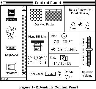 Figure 1–Extendible Control Panel
_______________________________________________________________________________
»OPERATION
_______________________________________________________________________________
When the Control Panel is opened it scans the System Folder for resource files of type cdev. Upon finding a cdev file it takes the file’s icon and name and adds it to the list at the left quarter of the Control Panel window. When the Control Panel has found all the cdev files, it puts General at the top of the list and opens the General cdev.
The factory-issue Control Panel has six cdevs in the scrollable list. The initial cdevs are, in order of appearance:
• General (all Macintoshes)
• Keyboard (all Macintoshes)
• Monitors (Macintosh II only)
• Mouse (all Macintoshes)
• Sound (Macintosh II only)
• Startup device (Macintosh SE and II )
The General cdev is always first, and comes up selected the first time the user opens the Control Panel.
Each cdev is self-contained, with a standard structure and interface that is supported by the Control Panel. The Control Panel handles actions that are common to all cdevs, such as putting up a dialog window and responding to window-related events, displaying dialog items and tracking controls. The cdev itself simply describes what’s in the dialog (except the cdev icon), and contains code for controlling whatever that cdev was designed to do. The division of labor between Control Panel and the individual cdevs follows.
The Control Panel will
• manage the modeless dialog window for the Control Panel as a whole,
and respond to events for the window, such as dragging or closing it
• query cdevs initially, to see if they should be displayed on the
current hardware
• manage the list of cdev icons, and respond to user actions on the
list, such as picking which cdev to run
• track user actions on cdev controls
• if requested by a cdev, draw rectangles within the cdev portion of
the window, and blank out (with light gray) any area of the window
not needed by the current cdev
• if requested by a cdev, display selected error conditions
• draw dialog items belonging to the cdev that’s displayed
• signal the current cdev to do its part in responding to specific events
The cdev should
• supply the standard resources that the Control Panel needs to run
any cdev (described below)
• draw and respond to user items
• be prepared to handle errors, as described later in this chapter
• initialize and shut down when signalled by the Control Panel to do so
• do any updating, activating, deactivating that can’t be done
automatically for dialog items
• respond to user keystrokes and hits on dialog items or controls,
when signalled by the Control Panel
• perform whatever actions that cdev was designed to do
When the user clicks a new control device to select it, the Control Panel signals the current cdev to shut down and removes any items in the dialog that belong it. For the new cdev, the Control Panel then loads its code, splices its dialog items into the dialog’s item list and draws them, signals the cdev to initialize, and begins signalling the new cdev, as needed, in response to user actions.
_______________________________________________________________________________
»Contents of Cdev Files
The cdev interface to the Control Panel has two parts: a standard set of resources that describe the cdev, and are contained in the cdev resource file; second, one of those resources is code, which contains a function that must respond to a well-defined set of messages that may be passed to the cdev by the Control Panel.
To be adopted by the Control Panel, a cdev file must contain at least these seven resources:
1. 'DITL' (ID = –4064)
2. 'mach' (ID = –4064)
3. 'nrct' (ID = –4064)
4. 'ICN#' (ID = –4064)
5. 'BNDL' (ID = –4064)
6. 'FREF' (ID = –4064)
7. 'cdev' (ID = –4064) the code resource
8. 'CURS' (ID = -4064)
These standard resources, and others that are unique to the cdev, fall in two halves of the same resource ID range, –4033 through –4064. IDs that fall in the range –4064 through –4049 are reserved for the resources in the Control Panel’s cdev interface. IDs in the range –4048 through –4033 can be used by individual cdevs. Cdevs that encroach on the Control Panel’s range risk conflicting with future releases of the Control Panel.
The rest of this subsection describes the standard cdev resources and the messages that the cdev can expect from the Control Panel. The sample cdev file at the end of this chapter has examples of the seven resources.
»'BNDL', 'ICN#', and 'FREF' Resources
The 'BNDL', 'ICN#' and 'FREF' resources enable the cdev to appear both in the Finder™ and Control Panel displays. (An owner resource is also needed for the cdev to display its correct icon in the Finder.)
»'DITL' Resource
The 'DITL' is a standard dialog item list, including all of the items in your cdev. When a cdev is opened, the Control Panel concatenates the 'DITL' to its own. The coordinates of a cdev’s dialog items are relative to the entire Control Panel window, not just the cdev portion of the window to the right of the list. To fall in the cdev section of the window, items must be entirely within the rectangle (1, 89, 253, 320).
Figure 1–Extendible Control Panel
_______________________________________________________________________________
»OPERATION
_______________________________________________________________________________
When the Control Panel is opened it scans the System Folder for resource files of type cdev. Upon finding a cdev file it takes the file’s icon and name and adds it to the list at the left quarter of the Control Panel window. When the Control Panel has found all the cdev files, it puts General at the top of the list and opens the General cdev.
The factory-issue Control Panel has six cdevs in the scrollable list. The initial cdevs are, in order of appearance:
• General (all Macintoshes)
• Keyboard (all Macintoshes)
• Monitors (Macintosh II only)
• Mouse (all Macintoshes)
• Sound (Macintosh II only)
• Startup device (Macintosh SE and II )
The General cdev is always first, and comes up selected the first time the user opens the Control Panel.
Each cdev is self-contained, with a standard structure and interface that is supported by the Control Panel. The Control Panel handles actions that are common to all cdevs, such as putting up a dialog window and responding to window-related events, displaying dialog items and tracking controls. The cdev itself simply describes what’s in the dialog (except the cdev icon), and contains code for controlling whatever that cdev was designed to do. The division of labor between Control Panel and the individual cdevs follows.
The Control Panel will
• manage the modeless dialog window for the Control Panel as a whole,
and respond to events for the window, such as dragging or closing it
• query cdevs initially, to see if they should be displayed on the
current hardware
• manage the list of cdev icons, and respond to user actions on the
list, such as picking which cdev to run
• track user actions on cdev controls
• if requested by a cdev, draw rectangles within the cdev portion of
the window, and blank out (with light gray) any area of the window
not needed by the current cdev
• if requested by a cdev, display selected error conditions
• draw dialog items belonging to the cdev that’s displayed
• signal the current cdev to do its part in responding to specific events
The cdev should
• supply the standard resources that the Control Panel needs to run
any cdev (described below)
• draw and respond to user items
• be prepared to handle errors, as described later in this chapter
• initialize and shut down when signalled by the Control Panel to do so
• do any updating, activating, deactivating that can’t be done
automatically for dialog items
• respond to user keystrokes and hits on dialog items or controls,
when signalled by the Control Panel
• perform whatever actions that cdev was designed to do
When the user clicks a new control device to select it, the Control Panel signals the current cdev to shut down and removes any items in the dialog that belong it. For the new cdev, the Control Panel then loads its code, splices its dialog items into the dialog’s item list and draws them, signals the cdev to initialize, and begins signalling the new cdev, as needed, in response to user actions.
_______________________________________________________________________________
»Contents of Cdev Files
The cdev interface to the Control Panel has two parts: a standard set of resources that describe the cdev, and are contained in the cdev resource file; second, one of those resources is code, which contains a function that must respond to a well-defined set of messages that may be passed to the cdev by the Control Panel.
To be adopted by the Control Panel, a cdev file must contain at least these seven resources:
1. 'DITL' (ID = –4064)
2. 'mach' (ID = –4064)
3. 'nrct' (ID = –4064)
4. 'ICN#' (ID = –4064)
5. 'BNDL' (ID = –4064)
6. 'FREF' (ID = –4064)
7. 'cdev' (ID = –4064) the code resource
8. 'CURS' (ID = -4064)
These standard resources, and others that are unique to the cdev, fall in two halves of the same resource ID range, –4033 through –4064. IDs that fall in the range –4064 through –4049 are reserved for the resources in the Control Panel’s cdev interface. IDs in the range –4048 through –4033 can be used by individual cdevs. Cdevs that encroach on the Control Panel’s range risk conflicting with future releases of the Control Panel.
The rest of this subsection describes the standard cdev resources and the messages that the cdev can expect from the Control Panel. The sample cdev file at the end of this chapter has examples of the seven resources.
»'BNDL', 'ICN#', and 'FREF' Resources
The 'BNDL', 'ICN#' and 'FREF' resources enable the cdev to appear both in the Finder™ and Control Panel displays. (An owner resource is also needed for the cdev to display its correct icon in the Finder.)
»'DITL' Resource
The 'DITL' is a standard dialog item list, including all of the items in your cdev. When a cdev is opened, the Control Panel concatenates the 'DITL' to its own. The coordinates of a cdev’s dialog items are relative to the entire Control Panel window, not just the cdev portion of the window to the right of the list. To fall in the cdev section of the window, items must be entirely within the rectangle (1, 89, 253, 320).
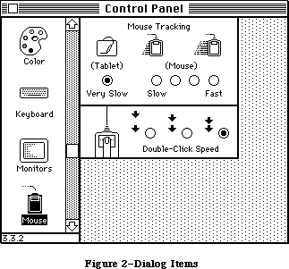 Figure 2–Dialog Items
»'mach' Resource
The 'mach' resource is used by the Control Panel to determine the machines on which this cdev can run. It contains two word-sized masks: the Softmask is compared to the global variable ROM85 to test for toolbox features (such as Color Quickdraw); the Hardmask is compared to the low memory global HwCfgFlgs to determine which hardware features are available. The cdev will show up if every bit that is 0 in the Softmask is 0 in ROM85 and every bit that is 1 in the Hardmask is 1 in HwCfgFlgs. If the Softmask is 0 and the Hardmask is $FFFF then the Control Panel sends the cdev a macDev call (described below), otherwise it does not. Mask examples:
Softmask Hardmask Action
0 $FFFF always call cdev with macDev message
$FFFF $0000 appear on all machines
$7FFF $0400 appear on machines with ADB
$3FFF $0000 appear on Macintosh II only
The 'mach' resource enables the Control Panel to cache information about each cdev. (The user can force a rebuild of the cache by holding down Command-Option while opening the Control Panel.)
»'nrct' Resource
The 'nrct' resource is a list of rectangles. The first word of the resource is the number of rectangles in the list; the rest of the resource contains the rectangle definitions, using eight bytes per rectangle in (top, left, bottom, right) order.
The Control Panel starts out with a light gray background pattern and then uses the rectangles to clear white space for the controls and to draw frames around them. The 'nrct' resource, along with the 'DITL' resource, defines the look of the cdev panel.
Rectangle coordinates are relative to the entire Control Panel window. To use all of the available space in the cdev area, use one rectangle with coordinates (–1, 87, 255, 322). (The coordinates differ from those given in 'DITL' by exactly two pixels, which is the width of the frame Control Panel draws around each rectangle.) To join two panels neatly, overlap their rectangles by one pixel on the side where they meet, so that the rectangle frames overlap too. For example, the two cdev rectangles in Figure 2 have the coordinates (–1, 87, 100, 266) and (98, 87, 159, 266).
If the number or sizes of rectangles you want varies (as in the Macintosh II Monitors cdev), the easiest way to manage it is to define rectangles covering the maximum area, and paint out those you don’t want at run time with the same gray pattern Control Panel uses, or frame them yourself.
»'cdev' Code Resource
The 'cdev' code resource contains all of your code to handle the other part of the cdev interface, the events that are passed to you by Control Panel. The very first piece of code in this resource must be the cdev function, as described below.
X-Ref: Technical Note #215
_______________________________________________________________________________
»CDEV CALL
_______________________________________________________________________________
The cdev function should be the first piece of code in your 'cdev' resource. Its calling sequence is as follows:
FUNCTION cdev(message, Item, numItems, CPanelID: INTEGER;
VAR theEvent: EventRecord; cdevValue: LONGINT; CPDialog:
DialogPtr) : LONGINT;
Field descriptions
message A message number, from the list defined below, that allows the
Control Panel to tell the cdev what event has just taken place.
Item For hitDev messages only: the dialog item number of the item
that was hit. Since the cdev’s DITL is appended to the Control
Panel’s DITL, the number of items preceding the cdev’s must be
subtracted to get a value that is meaningful to the cdev.
(See the hitDev message, described below.)
numItems The number of items in the DITL, belonging to the Control
Panel, that precede the cdev’s dialog items in the item list.
CPanelID The base resource ID of the Control Panel driver. This
value is private to the Control Panel.
theEvent For hit, null, activate, deactivate, and key events: the
event record for the event that caused the message. See
the Toolbox Event Manager for details of the EventRecord
structure.
cdevValue The value the cdev returned the last time it was called by
the Control Panel, or a return message from the Control Panel.
When a cdev is initialized it typically allocates some storage
for state information or other data it needs to run. Since
desk accessories in general and the Control Panel in
particular—and therefore cdevs—cannot have global variables,
the cdevValue, which is passed to the cdev for every message,
is often used for storing data. The cdevValue is also used
by the Control Panel to communicate error handling action to
the cdev. See “Storage in a Cdev” and “Cdev Error Checking”
later in this chapter.
CPDialog The Control Panel DialogPtr. This may be a color dialog on
Macintoshes that support color windows.
The function value returned will be one of three kinds. The Control Panel’s initial call to a cdev will be a macDev call, described below. The cdev responds with a function value that tells the Control Panel whether the cdev should be displayed or not. In subsequent calls the cdev function result may be an error code, or data that needs to be kept until the Control Panel’s next call. The function result is generally passed back to the cdev in the cdevValue parameter at the next cdev function call.
The cdev will be called with the current resource file set to the cdev file, the current grafPort set to the Control Panel’s dialog, and the default volume set to the System Folder of the current startup disk. The cdev must preserve all of these. Also note that the Control Panel sets the cursor to the cross cursor whenever it is above the cdev area of the Control Panel window. Your cdev thus has control of the cursor only during the call; if you change it, the Control Panel will immediately reset it.
Your cdev may be reentered, especially if you put up dialog or alert boxes. The Dialog Manager calls SystemEvent and SystemTask, which may cause a deactivate message to be sent while your cdev is still processing the previous message.
_______________________________________________________________________________
»Messages
The following cdev message values have been defined:
CONST
initDev = 0; {initialization}
hitDev = 1; {user clicked dialog item}
closeDev = 2; {user selected another cdev or CP closed}
nulDev = 3; {desk accessory run}
updateDev = 4; {update event}
activDev = 5; {activate event}
deActivDev = 6; {deactivate event}
keyEvtDev = 7; {key-down or auto-key event}
macDev = 8; {check machine characteristics}
undoDev = 9; {standard Edit menu undo}
cutDev =10; {standard Edit menu cut}
copyDev =11; {standard Edit menu copy}
pasteDev =12; {standard Edit menu paste}
clearDev =13; {standard Edit menu clear}
cursorDev =14; {cursor moved event}
The messages are described below.
Before dispatching to handle a specific message, all cdevs should have some common defensive behavior, for example ensuring that they have enough memory to run. Public-minded cdevs keep a minimum of memory allocated between calls, and memory that was free may be consumed by other applications while Control Panel is inactive, so it is important to check that there is enough memory available on every message.
As part of their memory check, cdevs that depend on various Toolbox packages should ensure that there’s still room to load them. Cdevs should also ignore any messages (except macDev) received before initialization, or after shutdown or an error.
Your cdev, as part of a desk accessory that may move from one invocation to another, cannot use global variables. This in turn means that you cannot set user item procedures for drawing user items in the 'DITL', because the procedure pointers will dangle if the code moves. Instead, you must draw your user items in response to update messages. Also, you must find Quickdraw globals by means of thePort if you need to reference them.
See the sample cdev for examples.
»The macDev Message
If the 'mach' resource has a 0 in Softmask and a –1 ($FFFF) in Hardmask, the first message a cdev will get is a macDev message. This is an opportunity for the cdev to determine whether it can run, and whether it should appear in the Control Panel’s cdev list. The cdev can do its own check to see which machine it is being run on, what hardware is connected, and what is in the slots (if it has slots). The cdev must then return a function result of 1 or 0. If a 0 is returned, the Control Panel will not display the cdev in the icon list. (Note that the Control Panel does not interpret this 0 or 1 as an error message as described under “Cdev Error Checking”.)
The macDev call happens only once, and only when Softmask and Hardmask are 0 and FFFF. It is always the first call made to the cdev.
»The initDev Message
InitDev is an initialization message sent to allow the cdev to allocate its private storage (if any) and do any initial settings to buttons or controls. This message is sent when the user clicks on the cdev’s icon.
Note that the dialog, cdev list, and all of the items in the cdev’s 'DITL' except user items will already have been drawn when the initDev message is sent.
If your cdev doesn’t need any storage it should return the value that was passed to it in cdevValue.
»The activDev Message
An activDev message is sent to the cdev on every activate event. It allows the cdev to reset any items that may have changed while the Control Panel was inactive. It also allows the cdev to send things such as “lists activate” messages.
»The updateDev Message
An updateDev message is sent to the cdev on every update event. It allows the cdev to perform any updating necessary aside from the standard dialog item updating provided by the Dialog Manager. For example, if the cdev resource contains a picture of the sound control bar, it will probably be a user item, and the picture of the control bar and the volume knob should be redrawn in response to update events.
Note that there is no mechanism for determining what to update, as the update region has already been reset. You must redraw all of your user items completely.
»The nulDev Message
A nulDev message is sent to the cdev on every Control Panel run event. This allows the cdev to perform tasks that need to be executed continuously
(insertion point blinking, for example).
A cdev cannot assume any particular timing of calls from applications. Don’t use nulDev to refresh settings; see activDev, above.
»The hitDev Message
A hitDev message is sent when the user has clicked an enabled dialog item that belongs to the cdev. The dialog item number of the item hit is passed in the Item parameter. Remember that the Control Panel’s items precede yours, so
you’ll want (Item – numItems) to determine which of your items was hit. If the Control Panel itself has n items, the first of the cdev’s items will be n+1 in the combined dialog item list. A cdev should not depend on any hardcoded value for numItems, since the number of items in Control Panel’s 'DITL' is likely to change in the future.
Factoring in numItems need not mean an increase in your code size, or passing and adding numItems everywhere, or foregoing the constants that most developers use to identify specific items. You can do it easily, and neatly, as follows:
1. Subtract numItems from Item right away, and refer to your dialog
items with constants as usual throughout the cdev.
2. Write simple envelope routines to enclose Dialog Manager procedures
that require item number arguments. Add numItems only locally,
within those routines and for the Dialog Manager calls only.
This is demonstrated in the sample cdev.
»The keyEvtDev Message
A keyEvtDev message is sent to the cdev on every keyDown event and autoKey event. It allows the cdev to process key events. On return to the Control Panel, the key event will be processed by a call to dialogSelect in the Dialog Manager. A cdev that does not want the Toolbox Event Manager to do any further processing should change the what field of the EventRecord to nullEvent before returning to the Control Panel.
»The deActivDev Message
A deActivDev message is sent to the cdev on every deactivate event. It allows the cdev to send deactivate messages to items such as lists.
»The closeDev Message
A closeDev message is sent to the cdev when either the Control Panel is closed or the user selects another cdev. When a cdev receives a closeDev message it should dispose of any storage it has allocated, including the handle stored in cdevValue, if any.
»The Standard Edit Menu Messages
Values 9 through 13 have been defined in order to provide the standard Edit menu functions of Undo, Cut, Copy, Paste, and Clear for applications that need to implement them.
X-Ref: Technical Note #2
X-Ref: Technical Note #215
X-Ref: Technical Note #251
_______________________________________________________________________________
»STORAGE IN A CDEV
_______________________________________________________________________________
Since normal global storage is not available, the Control Panel, like all desk accessories, uses a special mechanism to store values between calls. The cdevValue parameter in the cdev call extends this storage mechanism to cdevs.
If a cdev needs to store information between calls it should create a handle during the initDev call, and return it as the cdev function result. The Control Panel always returns such handles in the cdevValue parameter at the next call.
If the cdev is called with a closeDev message, or if it needs to shut down because of an error, then this handle and any pointers or handles within the storage area should be disposed of before returning to the Control Panel.
_______________________________________________________________________________
»CDEV ERROR CHECKING
_______________________________________________________________________________
Because a desk accessory may be called into many strange and wonderful situations, careful attention must be paid to error checking. The two most common error conditions are missing resources and lack of memory. Some error reporting and recovery facilities have been provided in the Control Panel to help with errors encountered in a cdev.
Because the Control Panel has no direct information about the cdev, the cdev’s code must be able to detect and recover from error conditions on its own. If the recovery cannot be effected the cdev must dispose of any memory it has allocated, and exit back to the Control Panel with an error code.
Following a shutdown, the Control Panel can help report the error condition to the user and prevent accidental reentry into the cdev that might result from such things as an update event. A cdev can request three different error reporting mechanisms from the Control Panel:
• If a memory error has occured, then, after the cdev has safely shut
itself down, it may request the Control Panel to issue an out-of-memory
error message and gray out (paint over with the background pattern) the
cdev area of the Control Panel window. It will remain grayed until
another cdev is selected. The Control Panel window itself is not
closed since other cdevs may still be able to function in the environment.
• If a resource error is detected, the cdev may request that a
can’t-find-needed-resource error message be issued.
• The cdev may display its own error message and then call on the
Control Panel to gray its area.
The Control Panel uses the cdevValue parameter to send status information to the cdev, and a proper cdev uses its function value to send information back to the Control Panel. In the absence of errors, the same value passes back and forth: the Control Panel puts the last function value it received into cdevValue when it calls the cdev; the cdev returns the value it finds there as the function value. The cdev may want to keep a handle to its own storage, in which case passing it as the function value ensures its availability, since the Control Panel will pass it back in cdevValue at the next call.
Four constants have been defined for this cdev/Control Panel communication:
CONST
cdevUnset = 3; {initial value passed in cdevValue}
cdevGenErr = -1; {generic cdev error}
cdevMemErr = 0; {insufficient memory for cdev execution}
cdevResErr = 1; {missing resource needed by cdev}
After the macDev call, the Control Panel sends cdevUnset in cdevValue, so that until an error occurs or the cdev uses its function value as a handle, cdevUnset is passed back and forth. If the cdev encounters an error, it should dispose of all handles and pointers it has set up, strip the stack back to the same position as a normal exit, and return one of the three error codes as the function result. The Control Panel will respond as follows:
Function Message to Control Panel Action
Result Control Panel
cdevGenErr The cdev has encountered an Gray out the cdev’s area,
error from which it cannot send a 0 in cdevValue in
recover, but do not put up succeeding cdev calls
an error dialog.
cdevMemErr The cdev has determined that Gray out cdev’s area, put
there is not enough memory to up error dialog, send a 0
execute; please put up a in cdevValue in succeeding
memory error dialog. cdev calls.
cdevResErr The cdev can’t find a needed Gray out cdev’s area, put
resource; please put up a up error dialog, send a 0
resource error dialog. in cdevValue in succeeding
cdev calls.
all other values, No error conditions. Send the value back in
either handles cdevValue.
or cdevUnset
The cdev code should check cdevValue at entry. A 0 means that the Control Panel has responded to a cdev error message by shutting down the cdev and displaying an error dialog if one was requested. The cdev should immediately exit.
Once the Control Panel has responded to an error message from a cdev it will no longer respond to any return values until another cdev is launched.
The sample cdev code presented next includes error checking.
_______________________________________________________________________________
»SAMPLE CDEV
_______________________________________________________________________________
Following is a REZ resource file containing resource definitions for a sample cdev. The cdev code resource is provided by the Pascal code that follows. When executed, the cdev puts up a control window that has two buttons, and displays how many messages it has received, as shown in Figure 3.
Figure 2–Dialog Items
»'mach' Resource
The 'mach' resource is used by the Control Panel to determine the machines on which this cdev can run. It contains two word-sized masks: the Softmask is compared to the global variable ROM85 to test for toolbox features (such as Color Quickdraw); the Hardmask is compared to the low memory global HwCfgFlgs to determine which hardware features are available. The cdev will show up if every bit that is 0 in the Softmask is 0 in ROM85 and every bit that is 1 in the Hardmask is 1 in HwCfgFlgs. If the Softmask is 0 and the Hardmask is $FFFF then the Control Panel sends the cdev a macDev call (described below), otherwise it does not. Mask examples:
Softmask Hardmask Action
0 $FFFF always call cdev with macDev message
$FFFF $0000 appear on all machines
$7FFF $0400 appear on machines with ADB
$3FFF $0000 appear on Macintosh II only
The 'mach' resource enables the Control Panel to cache information about each cdev. (The user can force a rebuild of the cache by holding down Command-Option while opening the Control Panel.)
»'nrct' Resource
The 'nrct' resource is a list of rectangles. The first word of the resource is the number of rectangles in the list; the rest of the resource contains the rectangle definitions, using eight bytes per rectangle in (top, left, bottom, right) order.
The Control Panel starts out with a light gray background pattern and then uses the rectangles to clear white space for the controls and to draw frames around them. The 'nrct' resource, along with the 'DITL' resource, defines the look of the cdev panel.
Rectangle coordinates are relative to the entire Control Panel window. To use all of the available space in the cdev area, use one rectangle with coordinates (–1, 87, 255, 322). (The coordinates differ from those given in 'DITL' by exactly two pixels, which is the width of the frame Control Panel draws around each rectangle.) To join two panels neatly, overlap their rectangles by one pixel on the side where they meet, so that the rectangle frames overlap too. For example, the two cdev rectangles in Figure 2 have the coordinates (–1, 87, 100, 266) and (98, 87, 159, 266).
If the number or sizes of rectangles you want varies (as in the Macintosh II Monitors cdev), the easiest way to manage it is to define rectangles covering the maximum area, and paint out those you don’t want at run time with the same gray pattern Control Panel uses, or frame them yourself.
»'cdev' Code Resource
The 'cdev' code resource contains all of your code to handle the other part of the cdev interface, the events that are passed to you by Control Panel. The very first piece of code in this resource must be the cdev function, as described below.
X-Ref: Technical Note #215
_______________________________________________________________________________
»CDEV CALL
_______________________________________________________________________________
The cdev function should be the first piece of code in your 'cdev' resource. Its calling sequence is as follows:
FUNCTION cdev(message, Item, numItems, CPanelID: INTEGER;
VAR theEvent: EventRecord; cdevValue: LONGINT; CPDialog:
DialogPtr) : LONGINT;
Field descriptions
message A message number, from the list defined below, that allows the
Control Panel to tell the cdev what event has just taken place.
Item For hitDev messages only: the dialog item number of the item
that was hit. Since the cdev’s DITL is appended to the Control
Panel’s DITL, the number of items preceding the cdev’s must be
subtracted to get a value that is meaningful to the cdev.
(See the hitDev message, described below.)
numItems The number of items in the DITL, belonging to the Control
Panel, that precede the cdev’s dialog items in the item list.
CPanelID The base resource ID of the Control Panel driver. This
value is private to the Control Panel.
theEvent For hit, null, activate, deactivate, and key events: the
event record for the event that caused the message. See
the Toolbox Event Manager for details of the EventRecord
structure.
cdevValue The value the cdev returned the last time it was called by
the Control Panel, or a return message from the Control Panel.
When a cdev is initialized it typically allocates some storage
for state information or other data it needs to run. Since
desk accessories in general and the Control Panel in
particular—and therefore cdevs—cannot have global variables,
the cdevValue, which is passed to the cdev for every message,
is often used for storing data. The cdevValue is also used
by the Control Panel to communicate error handling action to
the cdev. See “Storage in a Cdev” and “Cdev Error Checking”
later in this chapter.
CPDialog The Control Panel DialogPtr. This may be a color dialog on
Macintoshes that support color windows.
The function value returned will be one of three kinds. The Control Panel’s initial call to a cdev will be a macDev call, described below. The cdev responds with a function value that tells the Control Panel whether the cdev should be displayed or not. In subsequent calls the cdev function result may be an error code, or data that needs to be kept until the Control Panel’s next call. The function result is generally passed back to the cdev in the cdevValue parameter at the next cdev function call.
The cdev will be called with the current resource file set to the cdev file, the current grafPort set to the Control Panel’s dialog, and the default volume set to the System Folder of the current startup disk. The cdev must preserve all of these. Also note that the Control Panel sets the cursor to the cross cursor whenever it is above the cdev area of the Control Panel window. Your cdev thus has control of the cursor only during the call; if you change it, the Control Panel will immediately reset it.
Your cdev may be reentered, especially if you put up dialog or alert boxes. The Dialog Manager calls SystemEvent and SystemTask, which may cause a deactivate message to be sent while your cdev is still processing the previous message.
_______________________________________________________________________________
»Messages
The following cdev message values have been defined:
CONST
initDev = 0; {initialization}
hitDev = 1; {user clicked dialog item}
closeDev = 2; {user selected another cdev or CP closed}
nulDev = 3; {desk accessory run}
updateDev = 4; {update event}
activDev = 5; {activate event}
deActivDev = 6; {deactivate event}
keyEvtDev = 7; {key-down or auto-key event}
macDev = 8; {check machine characteristics}
undoDev = 9; {standard Edit menu undo}
cutDev =10; {standard Edit menu cut}
copyDev =11; {standard Edit menu copy}
pasteDev =12; {standard Edit menu paste}
clearDev =13; {standard Edit menu clear}
cursorDev =14; {cursor moved event}
The messages are described below.
Before dispatching to handle a specific message, all cdevs should have some common defensive behavior, for example ensuring that they have enough memory to run. Public-minded cdevs keep a minimum of memory allocated between calls, and memory that was free may be consumed by other applications while Control Panel is inactive, so it is important to check that there is enough memory available on every message.
As part of their memory check, cdevs that depend on various Toolbox packages should ensure that there’s still room to load them. Cdevs should also ignore any messages (except macDev) received before initialization, or after shutdown or an error.
Your cdev, as part of a desk accessory that may move from one invocation to another, cannot use global variables. This in turn means that you cannot set user item procedures for drawing user items in the 'DITL', because the procedure pointers will dangle if the code moves. Instead, you must draw your user items in response to update messages. Also, you must find Quickdraw globals by means of thePort if you need to reference them.
See the sample cdev for examples.
»The macDev Message
If the 'mach' resource has a 0 in Softmask and a –1 ($FFFF) in Hardmask, the first message a cdev will get is a macDev message. This is an opportunity for the cdev to determine whether it can run, and whether it should appear in the Control Panel’s cdev list. The cdev can do its own check to see which machine it is being run on, what hardware is connected, and what is in the slots (if it has slots). The cdev must then return a function result of 1 or 0. If a 0 is returned, the Control Panel will not display the cdev in the icon list. (Note that the Control Panel does not interpret this 0 or 1 as an error message as described under “Cdev Error Checking”.)
The macDev call happens only once, and only when Softmask and Hardmask are 0 and FFFF. It is always the first call made to the cdev.
»The initDev Message
InitDev is an initialization message sent to allow the cdev to allocate its private storage (if any) and do any initial settings to buttons or controls. This message is sent when the user clicks on the cdev’s icon.
Note that the dialog, cdev list, and all of the items in the cdev’s 'DITL' except user items will already have been drawn when the initDev message is sent.
If your cdev doesn’t need any storage it should return the value that was passed to it in cdevValue.
»The activDev Message
An activDev message is sent to the cdev on every activate event. It allows the cdev to reset any items that may have changed while the Control Panel was inactive. It also allows the cdev to send things such as “lists activate” messages.
»The updateDev Message
An updateDev message is sent to the cdev on every update event. It allows the cdev to perform any updating necessary aside from the standard dialog item updating provided by the Dialog Manager. For example, if the cdev resource contains a picture of the sound control bar, it will probably be a user item, and the picture of the control bar and the volume knob should be redrawn in response to update events.
Note that there is no mechanism for determining what to update, as the update region has already been reset. You must redraw all of your user items completely.
»The nulDev Message
A nulDev message is sent to the cdev on every Control Panel run event. This allows the cdev to perform tasks that need to be executed continuously
(insertion point blinking, for example).
A cdev cannot assume any particular timing of calls from applications. Don’t use nulDev to refresh settings; see activDev, above.
»The hitDev Message
A hitDev message is sent when the user has clicked an enabled dialog item that belongs to the cdev. The dialog item number of the item hit is passed in the Item parameter. Remember that the Control Panel’s items precede yours, so
you’ll want (Item – numItems) to determine which of your items was hit. If the Control Panel itself has n items, the first of the cdev’s items will be n+1 in the combined dialog item list. A cdev should not depend on any hardcoded value for numItems, since the number of items in Control Panel’s 'DITL' is likely to change in the future.
Factoring in numItems need not mean an increase in your code size, or passing and adding numItems everywhere, or foregoing the constants that most developers use to identify specific items. You can do it easily, and neatly, as follows:
1. Subtract numItems from Item right away, and refer to your dialog
items with constants as usual throughout the cdev.
2. Write simple envelope routines to enclose Dialog Manager procedures
that require item number arguments. Add numItems only locally,
within those routines and for the Dialog Manager calls only.
This is demonstrated in the sample cdev.
»The keyEvtDev Message
A keyEvtDev message is sent to the cdev on every keyDown event and autoKey event. It allows the cdev to process key events. On return to the Control Panel, the key event will be processed by a call to dialogSelect in the Dialog Manager. A cdev that does not want the Toolbox Event Manager to do any further processing should change the what field of the EventRecord to nullEvent before returning to the Control Panel.
»The deActivDev Message
A deActivDev message is sent to the cdev on every deactivate event. It allows the cdev to send deactivate messages to items such as lists.
»The closeDev Message
A closeDev message is sent to the cdev when either the Control Panel is closed or the user selects another cdev. When a cdev receives a closeDev message it should dispose of any storage it has allocated, including the handle stored in cdevValue, if any.
»The Standard Edit Menu Messages
Values 9 through 13 have been defined in order to provide the standard Edit menu functions of Undo, Cut, Copy, Paste, and Clear for applications that need to implement them.
X-Ref: Technical Note #2
X-Ref: Technical Note #215
X-Ref: Technical Note #251
_______________________________________________________________________________
»STORAGE IN A CDEV
_______________________________________________________________________________
Since normal global storage is not available, the Control Panel, like all desk accessories, uses a special mechanism to store values between calls. The cdevValue parameter in the cdev call extends this storage mechanism to cdevs.
If a cdev needs to store information between calls it should create a handle during the initDev call, and return it as the cdev function result. The Control Panel always returns such handles in the cdevValue parameter at the next call.
If the cdev is called with a closeDev message, or if it needs to shut down because of an error, then this handle and any pointers or handles within the storage area should be disposed of before returning to the Control Panel.
_______________________________________________________________________________
»CDEV ERROR CHECKING
_______________________________________________________________________________
Because a desk accessory may be called into many strange and wonderful situations, careful attention must be paid to error checking. The two most common error conditions are missing resources and lack of memory. Some error reporting and recovery facilities have been provided in the Control Panel to help with errors encountered in a cdev.
Because the Control Panel has no direct information about the cdev, the cdev’s code must be able to detect and recover from error conditions on its own. If the recovery cannot be effected the cdev must dispose of any memory it has allocated, and exit back to the Control Panel with an error code.
Following a shutdown, the Control Panel can help report the error condition to the user and prevent accidental reentry into the cdev that might result from such things as an update event. A cdev can request three different error reporting mechanisms from the Control Panel:
• If a memory error has occured, then, after the cdev has safely shut
itself down, it may request the Control Panel to issue an out-of-memory
error message and gray out (paint over with the background pattern) the
cdev area of the Control Panel window. It will remain grayed until
another cdev is selected. The Control Panel window itself is not
closed since other cdevs may still be able to function in the environment.
• If a resource error is detected, the cdev may request that a
can’t-find-needed-resource error message be issued.
• The cdev may display its own error message and then call on the
Control Panel to gray its area.
The Control Panel uses the cdevValue parameter to send status information to the cdev, and a proper cdev uses its function value to send information back to the Control Panel. In the absence of errors, the same value passes back and forth: the Control Panel puts the last function value it received into cdevValue when it calls the cdev; the cdev returns the value it finds there as the function value. The cdev may want to keep a handle to its own storage, in which case passing it as the function value ensures its availability, since the Control Panel will pass it back in cdevValue at the next call.
Four constants have been defined for this cdev/Control Panel communication:
CONST
cdevUnset = 3; {initial value passed in cdevValue}
cdevGenErr = -1; {generic cdev error}
cdevMemErr = 0; {insufficient memory for cdev execution}
cdevResErr = 1; {missing resource needed by cdev}
After the macDev call, the Control Panel sends cdevUnset in cdevValue, so that until an error occurs or the cdev uses its function value as a handle, cdevUnset is passed back and forth. If the cdev encounters an error, it should dispose of all handles and pointers it has set up, strip the stack back to the same position as a normal exit, and return one of the three error codes as the function result. The Control Panel will respond as follows:
Function Message to Control Panel Action
Result Control Panel
cdevGenErr The cdev has encountered an Gray out the cdev’s area,
error from which it cannot send a 0 in cdevValue in
recover, but do not put up succeeding cdev calls
an error dialog.
cdevMemErr The cdev has determined that Gray out cdev’s area, put
there is not enough memory to up error dialog, send a 0
execute; please put up a in cdevValue in succeeding
memory error dialog. cdev calls.
cdevResErr The cdev can’t find a needed Gray out cdev’s area, put
resource; please put up a up error dialog, send a 0
resource error dialog. in cdevValue in succeeding
cdev calls.
all other values, No error conditions. Send the value back in
either handles cdevValue.
or cdevUnset
The cdev code should check cdevValue at entry. A 0 means that the Control Panel has responded to a cdev error message by shutting down the cdev and displaying an error dialog if one was requested. The cdev should immediately exit.
Once the Control Panel has responded to an error message from a cdev it will no longer respond to any return values until another cdev is launched.
The sample cdev code presented next includes error checking.
_______________________________________________________________________________
»SAMPLE CDEV
_______________________________________________________________________________
Following is a REZ resource file containing resource definitions for a sample cdev. The cdev code resource is provided by the Pascal code that follows. When executed, the cdev puts up a control window that has two buttons, and displays how many messages it has received, as shown in Figure 3.
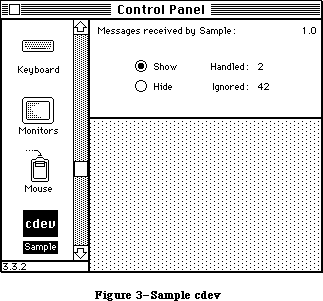 Figure 3–Sample cdev
/*
* File Sample.r
* Copyright © 1986, 1987 Apple Computer, Inc. All rights reserved.
*
* Sample cdev rez file
*/
#include "Types.r"
type 'samp' as 'STR ';
type 'nrct' {
integer = $$CountOf(RectArray);
array RectArray { rect; };
};
type 'mach' {
unsigned hex integer; /* Softmask */
unsigned hex integer; /* Hardmask */
};
/* The owner resource (related to the BNDL below). See Inside
Macintosh Volume IV for more information. */
resource 'samp' (0, purgeable) {
"Sample cdev 1.0d2, June 23, 1987"
};
resource 'BNDL' (-4064, purgeable) {
'samp', 0,
{ 'ICN#', {0, -4064},
'FREF', {0, -4064}
}
};
resource 'ICN#' (-4064, purgeable) {
{ /* array: 2 elements */
/* [1] */
$"FFFF FFFF 8000 0001 8000 0001 8000 0001"
$"800E 0001 800E 0001 800E 0001 800E 0001"
$"800E 0000 78FE 3E33 F9FE 7F33 F9FE 6333"
$"E1CE 7F33 E1CE 7F33 E1CE 603F F9FE 7F1E"
$"F9FE 7F1E 78FE 3F0C 8000 0001 8000 0001"
$"8000 0001 8000 0001 8000 0001 8000 0001"
$"8000 0001 8000 0001 8000 0001 8000 0001"
$"FFFF FFFF 0000 0000 0000 0000 0000 0000",
/* [2] */
$"FFFF FFFF FFFF FFFF FFFF FFFF FFFF FFFF"
$"FFFF FFFF FFFF FFFF FFFF FFFF FFFF FFFF"
$"FFFF FFFE 7FFF FFFF FFFF FFFF FFFF FFFF"
$"FFFF FFFF FFFF FFFF FFFF FFFF FFFF FFFE"
$"FFFF FFFE 7FFF FFFE FFFF FFFF FFFF FFFF"
$"FFFF FFFF FFFF FFFF FFFF FFFF FFFF FFFF"
$"FFFF FFFF FFFF FFFF FFFF FFFF FFFF FFFF"
$"FFFF FFFF 0000 0000 0000 0000 0000 0000"
}
};
resource 'FREF' (-4064, purgeable) {
'cdev', 0, ""
};
resource 'mach' (-4064, purgeable) {
0xFFFF,
0
};
resource 'nrct' (-4064, purgeable) {
{ /* array RectArray: 1 elements */
{-1, 87, 79, 322}
}
};
resource 'DITL' (-4064, purgeable) {
{ /* array DITLarray: 8 elements */
{4, 287, 16, 320}, StaticText {disabled, "1.0d2"};
{4, 92, 16, 280}, StaticText {disabled, "Messages }
{ received by Sample:"};
{26, 122, 43, 170}, Control {enabled, -4048};
{42, 122, 59, 170}, Control {enabled, -4047};
{29, 190, 41, 230}, StaticText {disabled, "Handled:"};
{45, 190, 57, 230}, StaticText {disabled, "Ignored:"};
{29, 240, 39, 300}, UserItem {disabled};
{45, 240, 55, 300}, UserItem {disabled}
}
};
/*=================================================================
* Resources that are private to the Sample cdev (IDs for these
* must fall in the range -4048 to -4033). All those above (-4064
* to -4049) are standard for every cdev, and specified by Control
* Panel. */
resource 'CNTL' (-4048, purgeable) {
{26, 122, 43, 170}, 0, visible, 1, 0, radioButProcUseWFont, 0, }
{ "Show"
};
resource 'CNTL' (-4047, purgeable) {
{42, 122, 59, 170}, 0, visible, 1, 0, radioButProcUseWFont, 0, }
{ "Hide"
};
The Pascal source code for the 'cdev' code resource:
{Copyright © 1986, 1987 Apple Computer, Inc. All rights reserved.}
{Sample: A small cdev code resource for use by Control Panel 3.0. The }
{ cdev has two radio buttons, labeled "Hide" and "Show", which cause }
{ four other items to be visible or invisible. The four }
{ visible/hidden items are the number of messages handled by the cdev, }
{ the number ignored, and titles for those two counts. Note that }
{ Sample violates the prime directive for cdevs, i.e. that it do }
{ something that's really useful in Control Panel…}
{$D+} {turn debugging symbols on}
UNIT cdev;
INTERFACE
USES
MemTypes, QuickDraw, OSIntf, ToolIntf, PackIntf;
FUNCTION Sample (message, item, numItems, CPanelID: INTEGER;
theEvent: EventRecord; cdevValue: LONGINT;
CPDialog: DialogPtr) : LONGINT;
IMPLEMENTATION
CONST
{ Constants for all of Sample's dialog items }
iVersion = 1; {cdev's version number is just staticText}
iTitle = 2; {title for Sample is just staticText}
iShowCounts = 3; {show the events handled/ignored}
iHideCounts = 4; {hide the events handled/ignored}
iTitleHandled = 5; {title for events handled count}
iTitleIgnored = 6; {title for events ignored count}
iHandled = 7; {user item for number of events handled}
iIgnored = 8; {user item for number of events ignored}
TYPE
SampleStorage = RECORD
dlgPtr: DialogPtr;
dlgItems: INTEGER;
countShown: BOOLEAN;
msgHandled: INTEGER;
msgIgnored: INTEGER;
END;
SamplePtr = ^SampleStorage;
SampleHdl = ^SamplePtr;
FUNCTION InitSample (CPDialog: DialogPtr;
numItems: INTEGER): LONGINT; FORWARD;
FUNCTION EnoughRoomToRun (VAR cdevValue: LONGINT) : BOOLEAN; FORWARD;
PROCEDURE CountMessage (ourHandle: SampleHdl; handledIt: BOOLEAN); FORWARD;
PROCEDURE HitSample (ourHandle: SampleHdl; item: INTEGER); FORWARD;
PROCEDURE DrawSampleItem (ourHandle: SampleHdl; item: INTEGER); FORWARD;
FUNCTION IGetCtlHand (ourHandle: SampleHdl;
item: INTEGER): ControlHandle; FORWARD;
PROCEDURE IGetRect (ourHandle: SampleHdl; item: INTEGER;
VAR itemRect: Rect); FORWARD;
PROCEDURE IHide (ourHandle: SampleHdl; item: INTEGER); FORWARD;
PROCEDURE IShow (ourHandle: SampleHdl; item: INTEGER); FORWARD;
PROCEDURE IInvalidate (ourHandle: SampleHdl; item: INTEGER); FORWARD;
{----------------------------------------------------------------------}
{Sample: the cdev dispatch function, as documented above. The cdev }
{ function MUST be the first code in the code resource; Control Panel }
{ jumps to the first location in the 'cdev' code resource to dispatch }
{ messages to the cdev. }
FUNCTION Sample (message, item, numItems, CPanelID: INTEGER;
theEvent: EventRecord; cdevValue: LONGINT;
CPDialog: DialogPtr) : LONGINT;
VAR
i: INTEGER;
handledIt: BOOLEAN;
ourHandle: SampleHdl;
storageExpected: BOOLEAN;
BEGIN
{Do a validity check before trying to handle the message. }
{ cdevValue is initialized to cdevUnset by Control Panel; zero }
{ is the new cdevValue after any error return.}
storageExpected := NOT ((message = initDev)
OR (message = macDev));
IF storageExpected AND ((cdevValue = 0)
OR (cdevValue = cdevUnset))
THEN cdevValue := 0
{Equally important, we must check that there's still enough }
{ memory available for Sample to run, on every message. Memory }
{ can easily be consumed by other apps, etc, between messages, }
{ and (to be neighborly) we don't keep anything around between }
{ messages except the handle in cdevValue.}
ELSE IF storageExpected & NOT EnoughRoomToRun (cdevValue) THEN
BEGIN
{We're past initialization, and have been hit with a memory }
{ squeeze. Escape now, averting mayhem.}
END
ELSE
BEGIN
handledIt := TRUE;
ourHandle := SampleHdl (cdevValue);
CASE message OF
initDev: IF EnoughRoomToRun (cdevValue) THEN
BEGIN
cdevValue := InitSample
(CPDialog, numItems);
ourHandle := SampleHdl
(cdevValue);
END;
closeDev: IF ourHandle <> NIL THEN
BEGIN
DisposHandle (Handle
(ourHandle));
cdevValue := 0;
ourHandle := NIL;
END;
hitDev: HitSample (ourHandle, item - numItems);
updateDev: FOR i := iHandled TO iIgnored DO
DrawSampleItem (ourHandle, i);
OTHERWISE handledIt := FALSE;
END;
IF ourHandle <> NIL THEN
CountMessage(ourHandle, handledIt);
END;
Sample := cdevValue;
END;
{----------------------------------------------------------------------}
{InitSample: Initialize the cdev}
FUNCTION InitSample (CPDialog: DialogPtr; numItems: INTEGER): LONGINT;
VAR
i: INTEGER;
ourHandle: SampleHdl;
BEGIN
ourHandle := SampleHdl (NewHandle (SIZEOF (SampleStorage)));
IF ourHandle <> NIL THEN
BEGIN
WITH ourHandle^^ DO
BEGIN
dlgPtr := CPDialog;
dlgItems := numItems;
msgHandled := 0;
msgIgnored := 0;
countShown := TRUE;
END;
FOR i := iShowCounts TO iHideCounts DO
SetCtlValue (IGetCtlHand (ourHandle, i), ORD (i = iShowCounts));
END;
InitSample := ORD4 (ourHandle);
END;
{----------------------------------------------------------------------}
{EnoughRoomToRun: check that we still have room to run; close up if not }
FUNCTION EnoughRoomToRun (VAR cdevValue: LONGINT) : BOOLEAN;
VAR
error: INTEGER;
packHand: Handle;
BEGIN
{Make sure there is still room for the maximum amount of memory }
{ needed to process any event, AND for any packages or other }
{ resources you need at the same time. If you allocate lots of }
{ storage, you should account for that also if it hasn't been }
{ allocated yet. Sample needs the Binary/Decimal conversion }
{ package to display the event counts. }
{ In the interest of simplicity, this does NOT take into account }
{ the fact that PACK 7 may be in ROM; it really should.}
packHand := GetResource ('PACK', 7);
IF packHand <> NIL THEN
BEGIN
EnoughRoomToRun := TRUE;
EXIT (EnoughRoomToRun);
END
ELSE IF ResError = resNotFound
THEN error := cdevResErr {a needed resource is missing}
ELSE error := cdevMemErr; {assume memFull otherwise}
{There's too little memory to load the package. Try to fail }
{ gracefully, disposing of our storage if it's already been }
{ allocated, because the error code we return to Control Panel }
{ will replace cdevValue.}
IF (cdevValue <> cdevUnset) AND (Handle (cdevValue) <> NIL) THEN
DisposHandle (Handle (cdevValue));
cdevValue := error;
EnoughRoomToRun := FALSE;
END;
{----------------------------------------------------------------------}
{CountMessage: count message from Control Panel as handled/ignored}
PROCEDURE CountMessage (ourHandle: SampleHdl; handledIt: BOOLEAN);
BEGIN
IF ourHandle <> NIL THEN
WITH ourHandle^^ DO
IF handledIt THEN
BEGIN
msgHandled := msgHandled + 1;
DrawSampleItem (ourHandle, iHandled);
END
ELSE
BEGIN
msgIgnored := msgIgnored + 1;
DrawSampleItem (ourHandle, iIgnored);
END
END;
{----------------------------------------------------------------------}
{HitSample: Handle a hit in one of our DITL items}
PROCEDURE HitSample (ourHandle: SampleHdl; item: INTEGER);
VAR
i: INTEGER;
BEGIN
WITH ourHandle^^ DO
IF countShown <> (item = iShowCounts)
THEN countShown := (item = iShowCounts)
ELSE EXIT (HitSample);
FOR i := iShowCounts TO iHideCounts DO
SetCtlValue (IGetCtlHand (ourHandle, i), ORD (i = item));
FOR i := iTitleHandled TO iIgnored DO
BEGIN
IF item = iShowCounts
THEN IShow (ourHandle, i)
ELSE IHide (ourHandle, i);
IInvalidate (ourHandle, i);
END;
END;
{----------------------------------------------------------------------}
{DrawSampleItem: Draw one of our DITL user items}
PROCEDURE DrawSampleItem (ourHandle: SampleHdl; item: INTEGER);
VAR
itemRect: Rect;
s: Str255;
BEGIN
{Note that Sample draws its user items explicitly, rather than }
{ installing a pointer to the draw procedure in the dialog item. }
{ Since the cdev's code may move between messages, the pointer }
{ would become invalid (Control Panel often calls the dialog }
{ manager before the cdev, so there's no chance to refresh the }
{ pointer either).}
IGetRect (ourHandle, item, itemRect);
WITH ourHandle^^ DO
BEGIN
SetPort (dlgPtr);
IF item = iHandled
THEN NumToString (msgHandled, s)
ELSE NumToString (msgIgnored, s);
END;
WITH itemRect DO
MoveTo (left, bottom);
TextMode (srcCopy);
DrawString (s);
TextMode (srcOr);
END;
{----------------------------------------------------------------------}
{Simple routines enclosing the dialog manager functions we need, to}
{ tack on numItems (so we can refer to our items with constants }
{ everywhere else). }
{IGetCtlHand: get control handle for given dialog item}
{IGetRect: get rectangle for given dialog item}
{IHide: hide dialog item}
{IShow: show dialog item}
{IInvalidate: erase & invalidate dialog item}
FUNCTION IGetCtlHand (ourHandle: SampleHdl; item: INTEGER): ControlHandle;
VAR
itemHand: Handle;
itemRect: Rect;
itemType: INTEGER;
BEGIN
WITH ourHandle^^ DO
GetDItem (dlgPtr, item + dlgItems, itemType, itemHand, itemRect);
IGetCtlHand := ControlHandle (itemHand);
END;
PROCEDURE IGetRect (ourHandle: SampleHdl; item: INTEGER; VAR itemRect: Rect);
VAR
itemType: INTEGER;
itemHand: Handle;
BEGIN
WITH ourHandle^^ DO
GetDItem (dlgPtr, item + dlgItems, itemType, itemHand, itemRect);
END;
PROCEDURE IHide (ourHandle: SampleHdl; item: INTEGER);
BEGIN
WITH ourHandle^^ DO
HideDItem (dlgPtr, item + dlgItems);
END;
PROCEDURE IShow (ourHandle: SampleHdl; item: INTEGER);
BEGIN
WITH ourHandle^^ DO
ShowDItem (dlgPtr, item + dlgItems);
END;
PROCEDURE IInvalidate (ourHandle: SampleHdl; item: INTEGER);
VAR
itemRect: Rect;
BEGIN
IGetRect (ourHandle, item, itemRect);
EraseRect (itemRect);
InvalRect (itemRect);
END;
END.
_______________________________________________________________________________
»SUMMARY OF THE CONTROL PANEL
_______________________________________________________________________________
Constants
CONST
{ messages }
initDev = 0; {initialization}
hitDev = 1; {user clicked on dialog item}
closeDev = 2; {user selected another cdev or CP closed}
nulDev = 3; {desk accessory run}
updateDev = 4; {update event}
activDev = 5; {activate event}
deActivDev = 6; {deactivate event}
keyEvtDev = 7; {key down or autokey event}
macDev = 8; {check machine characteristics}
undoDev = 9; {standard Edit menu undo}
cutDev =10; {standard Edit menu cut}
copyDev =11; {standard Edit menu copy}
pasteDev =12; {standard Edit menu paste}
clearDev =13; {standard Edit menu clear}
cursorDev =14; {cursor moved event}
{ Special cdevValue values }
cdevGenErr = -1; {general error; gray cdev w/o alert}
cdevMemErr = 0; {memory shortfall; alert user please}
cdevResErr = 1; {couldn't get a needed resource; alert}
cdevUnset = 3; {cdevValue is initialized to this}
__________________________________________________________________
Routines
FUNCTION cdev(message, Item, numItems, CPanelID : INTEGER;
VAR theEvent : EventRecord; cdevValue : LONGINT;
CPDialog : DialogPtr) : LONGINT;
Further Reference:
_______________________________________________________________________________
Technical Note #215, “New” cdev Messages
Technical Note #251, Safe cdevs
32-Bit QuickDraw Documentation
Figure 3–Sample cdev
/*
* File Sample.r
* Copyright © 1986, 1987 Apple Computer, Inc. All rights reserved.
*
* Sample cdev rez file
*/
#include "Types.r"
type 'samp' as 'STR ';
type 'nrct' {
integer = $$CountOf(RectArray);
array RectArray { rect; };
};
type 'mach' {
unsigned hex integer; /* Softmask */
unsigned hex integer; /* Hardmask */
};
/* The owner resource (related to the BNDL below). See Inside
Macintosh Volume IV for more information. */
resource 'samp' (0, purgeable) {
"Sample cdev 1.0d2, June 23, 1987"
};
resource 'BNDL' (-4064, purgeable) {
'samp', 0,
{ 'ICN#', {0, -4064},
'FREF', {0, -4064}
}
};
resource 'ICN#' (-4064, purgeable) {
{ /* array: 2 elements */
/* [1] */
$"FFFF FFFF 8000 0001 8000 0001 8000 0001"
$"800E 0001 800E 0001 800E 0001 800E 0001"
$"800E 0000 78FE 3E33 F9FE 7F33 F9FE 6333"
$"E1CE 7F33 E1CE 7F33 E1CE 603F F9FE 7F1E"
$"F9FE 7F1E 78FE 3F0C 8000 0001 8000 0001"
$"8000 0001 8000 0001 8000 0001 8000 0001"
$"8000 0001 8000 0001 8000 0001 8000 0001"
$"FFFF FFFF 0000 0000 0000 0000 0000 0000",
/* [2] */
$"FFFF FFFF FFFF FFFF FFFF FFFF FFFF FFFF"
$"FFFF FFFF FFFF FFFF FFFF FFFF FFFF FFFF"
$"FFFF FFFE 7FFF FFFF FFFF FFFF FFFF FFFF"
$"FFFF FFFF FFFF FFFF FFFF FFFF FFFF FFFE"
$"FFFF FFFE 7FFF FFFE FFFF FFFF FFFF FFFF"
$"FFFF FFFF FFFF FFFF FFFF FFFF FFFF FFFF"
$"FFFF FFFF FFFF FFFF FFFF FFFF FFFF FFFF"
$"FFFF FFFF 0000 0000 0000 0000 0000 0000"
}
};
resource 'FREF' (-4064, purgeable) {
'cdev', 0, ""
};
resource 'mach' (-4064, purgeable) {
0xFFFF,
0
};
resource 'nrct' (-4064, purgeable) {
{ /* array RectArray: 1 elements */
{-1, 87, 79, 322}
}
};
resource 'DITL' (-4064, purgeable) {
{ /* array DITLarray: 8 elements */
{4, 287, 16, 320}, StaticText {disabled, "1.0d2"};
{4, 92, 16, 280}, StaticText {disabled, "Messages }
{ received by Sample:"};
{26, 122, 43, 170}, Control {enabled, -4048};
{42, 122, 59, 170}, Control {enabled, -4047};
{29, 190, 41, 230}, StaticText {disabled, "Handled:"};
{45, 190, 57, 230}, StaticText {disabled, "Ignored:"};
{29, 240, 39, 300}, UserItem {disabled};
{45, 240, 55, 300}, UserItem {disabled}
}
};
/*=================================================================
* Resources that are private to the Sample cdev (IDs for these
* must fall in the range -4048 to -4033). All those above (-4064
* to -4049) are standard for every cdev, and specified by Control
* Panel. */
resource 'CNTL' (-4048, purgeable) {
{26, 122, 43, 170}, 0, visible, 1, 0, radioButProcUseWFont, 0, }
{ "Show"
};
resource 'CNTL' (-4047, purgeable) {
{42, 122, 59, 170}, 0, visible, 1, 0, radioButProcUseWFont, 0, }
{ "Hide"
};
The Pascal source code for the 'cdev' code resource:
{Copyright © 1986, 1987 Apple Computer, Inc. All rights reserved.}
{Sample: A small cdev code resource for use by Control Panel 3.0. The }
{ cdev has two radio buttons, labeled "Hide" and "Show", which cause }
{ four other items to be visible or invisible. The four }
{ visible/hidden items are the number of messages handled by the cdev, }
{ the number ignored, and titles for those two counts. Note that }
{ Sample violates the prime directive for cdevs, i.e. that it do }
{ something that's really useful in Control Panel…}
{$D+} {turn debugging symbols on}
UNIT cdev;
INTERFACE
USES
MemTypes, QuickDraw, OSIntf, ToolIntf, PackIntf;
FUNCTION Sample (message, item, numItems, CPanelID: INTEGER;
theEvent: EventRecord; cdevValue: LONGINT;
CPDialog: DialogPtr) : LONGINT;
IMPLEMENTATION
CONST
{ Constants for all of Sample's dialog items }
iVersion = 1; {cdev's version number is just staticText}
iTitle = 2; {title for Sample is just staticText}
iShowCounts = 3; {show the events handled/ignored}
iHideCounts = 4; {hide the events handled/ignored}
iTitleHandled = 5; {title for events handled count}
iTitleIgnored = 6; {title for events ignored count}
iHandled = 7; {user item for number of events handled}
iIgnored = 8; {user item for number of events ignored}
TYPE
SampleStorage = RECORD
dlgPtr: DialogPtr;
dlgItems: INTEGER;
countShown: BOOLEAN;
msgHandled: INTEGER;
msgIgnored: INTEGER;
END;
SamplePtr = ^SampleStorage;
SampleHdl = ^SamplePtr;
FUNCTION InitSample (CPDialog: DialogPtr;
numItems: INTEGER): LONGINT; FORWARD;
FUNCTION EnoughRoomToRun (VAR cdevValue: LONGINT) : BOOLEAN; FORWARD;
PROCEDURE CountMessage (ourHandle: SampleHdl; handledIt: BOOLEAN); FORWARD;
PROCEDURE HitSample (ourHandle: SampleHdl; item: INTEGER); FORWARD;
PROCEDURE DrawSampleItem (ourHandle: SampleHdl; item: INTEGER); FORWARD;
FUNCTION IGetCtlHand (ourHandle: SampleHdl;
item: INTEGER): ControlHandle; FORWARD;
PROCEDURE IGetRect (ourHandle: SampleHdl; item: INTEGER;
VAR itemRect: Rect); FORWARD;
PROCEDURE IHide (ourHandle: SampleHdl; item: INTEGER); FORWARD;
PROCEDURE IShow (ourHandle: SampleHdl; item: INTEGER); FORWARD;
PROCEDURE IInvalidate (ourHandle: SampleHdl; item: INTEGER); FORWARD;
{----------------------------------------------------------------------}
{Sample: the cdev dispatch function, as documented above. The cdev }
{ function MUST be the first code in the code resource; Control Panel }
{ jumps to the first location in the 'cdev' code resource to dispatch }
{ messages to the cdev. }
FUNCTION Sample (message, item, numItems, CPanelID: INTEGER;
theEvent: EventRecord; cdevValue: LONGINT;
CPDialog: DialogPtr) : LONGINT;
VAR
i: INTEGER;
handledIt: BOOLEAN;
ourHandle: SampleHdl;
storageExpected: BOOLEAN;
BEGIN
{Do a validity check before trying to handle the message. }
{ cdevValue is initialized to cdevUnset by Control Panel; zero }
{ is the new cdevValue after any error return.}
storageExpected := NOT ((message = initDev)
OR (message = macDev));
IF storageExpected AND ((cdevValue = 0)
OR (cdevValue = cdevUnset))
THEN cdevValue := 0
{Equally important, we must check that there's still enough }
{ memory available for Sample to run, on every message. Memory }
{ can easily be consumed by other apps, etc, between messages, }
{ and (to be neighborly) we don't keep anything around between }
{ messages except the handle in cdevValue.}
ELSE IF storageExpected & NOT EnoughRoomToRun (cdevValue) THEN
BEGIN
{We're past initialization, and have been hit with a memory }
{ squeeze. Escape now, averting mayhem.}
END
ELSE
BEGIN
handledIt := TRUE;
ourHandle := SampleHdl (cdevValue);
CASE message OF
initDev: IF EnoughRoomToRun (cdevValue) THEN
BEGIN
cdevValue := InitSample
(CPDialog, numItems);
ourHandle := SampleHdl
(cdevValue);
END;
closeDev: IF ourHandle <> NIL THEN
BEGIN
DisposHandle (Handle
(ourHandle));
cdevValue := 0;
ourHandle := NIL;
END;
hitDev: HitSample (ourHandle, item - numItems);
updateDev: FOR i := iHandled TO iIgnored DO
DrawSampleItem (ourHandle, i);
OTHERWISE handledIt := FALSE;
END;
IF ourHandle <> NIL THEN
CountMessage(ourHandle, handledIt);
END;
Sample := cdevValue;
END;
{----------------------------------------------------------------------}
{InitSample: Initialize the cdev}
FUNCTION InitSample (CPDialog: DialogPtr; numItems: INTEGER): LONGINT;
VAR
i: INTEGER;
ourHandle: SampleHdl;
BEGIN
ourHandle := SampleHdl (NewHandle (SIZEOF (SampleStorage)));
IF ourHandle <> NIL THEN
BEGIN
WITH ourHandle^^ DO
BEGIN
dlgPtr := CPDialog;
dlgItems := numItems;
msgHandled := 0;
msgIgnored := 0;
countShown := TRUE;
END;
FOR i := iShowCounts TO iHideCounts DO
SetCtlValue (IGetCtlHand (ourHandle, i), ORD (i = iShowCounts));
END;
InitSample := ORD4 (ourHandle);
END;
{----------------------------------------------------------------------}
{EnoughRoomToRun: check that we still have room to run; close up if not }
FUNCTION EnoughRoomToRun (VAR cdevValue: LONGINT) : BOOLEAN;
VAR
error: INTEGER;
packHand: Handle;
BEGIN
{Make sure there is still room for the maximum amount of memory }
{ needed to process any event, AND for any packages or other }
{ resources you need at the same time. If you allocate lots of }
{ storage, you should account for that also if it hasn't been }
{ allocated yet. Sample needs the Binary/Decimal conversion }
{ package to display the event counts. }
{ In the interest of simplicity, this does NOT take into account }
{ the fact that PACK 7 may be in ROM; it really should.}
packHand := GetResource ('PACK', 7);
IF packHand <> NIL THEN
BEGIN
EnoughRoomToRun := TRUE;
EXIT (EnoughRoomToRun);
END
ELSE IF ResError = resNotFound
THEN error := cdevResErr {a needed resource is missing}
ELSE error := cdevMemErr; {assume memFull otherwise}
{There's too little memory to load the package. Try to fail }
{ gracefully, disposing of our storage if it's already been }
{ allocated, because the error code we return to Control Panel }
{ will replace cdevValue.}
IF (cdevValue <> cdevUnset) AND (Handle (cdevValue) <> NIL) THEN
DisposHandle (Handle (cdevValue));
cdevValue := error;
EnoughRoomToRun := FALSE;
END;
{----------------------------------------------------------------------}
{CountMessage: count message from Control Panel as handled/ignored}
PROCEDURE CountMessage (ourHandle: SampleHdl; handledIt: BOOLEAN);
BEGIN
IF ourHandle <> NIL THEN
WITH ourHandle^^ DO
IF handledIt THEN
BEGIN
msgHandled := msgHandled + 1;
DrawSampleItem (ourHandle, iHandled);
END
ELSE
BEGIN
msgIgnored := msgIgnored + 1;
DrawSampleItem (ourHandle, iIgnored);
END
END;
{----------------------------------------------------------------------}
{HitSample: Handle a hit in one of our DITL items}
PROCEDURE HitSample (ourHandle: SampleHdl; item: INTEGER);
VAR
i: INTEGER;
BEGIN
WITH ourHandle^^ DO
IF countShown <> (item = iShowCounts)
THEN countShown := (item = iShowCounts)
ELSE EXIT (HitSample);
FOR i := iShowCounts TO iHideCounts DO
SetCtlValue (IGetCtlHand (ourHandle, i), ORD (i = item));
FOR i := iTitleHandled TO iIgnored DO
BEGIN
IF item = iShowCounts
THEN IShow (ourHandle, i)
ELSE IHide (ourHandle, i);
IInvalidate (ourHandle, i);
END;
END;
{----------------------------------------------------------------------}
{DrawSampleItem: Draw one of our DITL user items}
PROCEDURE DrawSampleItem (ourHandle: SampleHdl; item: INTEGER);
VAR
itemRect: Rect;
s: Str255;
BEGIN
{Note that Sample draws its user items explicitly, rather than }
{ installing a pointer to the draw procedure in the dialog item. }
{ Since the cdev's code may move between messages, the pointer }
{ would become invalid (Control Panel often calls the dialog }
{ manager before the cdev, so there's no chance to refresh the }
{ pointer either).}
IGetRect (ourHandle, item, itemRect);
WITH ourHandle^^ DO
BEGIN
SetPort (dlgPtr);
IF item = iHandled
THEN NumToString (msgHandled, s)
ELSE NumToString (msgIgnored, s);
END;
WITH itemRect DO
MoveTo (left, bottom);
TextMode (srcCopy);
DrawString (s);
TextMode (srcOr);
END;
{----------------------------------------------------------------------}
{Simple routines enclosing the dialog manager functions we need, to}
{ tack on numItems (so we can refer to our items with constants }
{ everywhere else). }
{IGetCtlHand: get control handle for given dialog item}
{IGetRect: get rectangle for given dialog item}
{IHide: hide dialog item}
{IShow: show dialog item}
{IInvalidate: erase & invalidate dialog item}
FUNCTION IGetCtlHand (ourHandle: SampleHdl; item: INTEGER): ControlHandle;
VAR
itemHand: Handle;
itemRect: Rect;
itemType: INTEGER;
BEGIN
WITH ourHandle^^ DO
GetDItem (dlgPtr, item + dlgItems, itemType, itemHand, itemRect);
IGetCtlHand := ControlHandle (itemHand);
END;
PROCEDURE IGetRect (ourHandle: SampleHdl; item: INTEGER; VAR itemRect: Rect);
VAR
itemType: INTEGER;
itemHand: Handle;
BEGIN
WITH ourHandle^^ DO
GetDItem (dlgPtr, item + dlgItems, itemType, itemHand, itemRect);
END;
PROCEDURE IHide (ourHandle: SampleHdl; item: INTEGER);
BEGIN
WITH ourHandle^^ DO
HideDItem (dlgPtr, item + dlgItems);
END;
PROCEDURE IShow (ourHandle: SampleHdl; item: INTEGER);
BEGIN
WITH ourHandle^^ DO
ShowDItem (dlgPtr, item + dlgItems);
END;
PROCEDURE IInvalidate (ourHandle: SampleHdl; item: INTEGER);
VAR
itemRect: Rect;
BEGIN
IGetRect (ourHandle, item, itemRect);
EraseRect (itemRect);
InvalRect (itemRect);
END;
END.
_______________________________________________________________________________
»SUMMARY OF THE CONTROL PANEL
_______________________________________________________________________________
Constants
CONST
{ messages }
initDev = 0; {initialization}
hitDev = 1; {user clicked on dialog item}
closeDev = 2; {user selected another cdev or CP closed}
nulDev = 3; {desk accessory run}
updateDev = 4; {update event}
activDev = 5; {activate event}
deActivDev = 6; {deactivate event}
keyEvtDev = 7; {key down or autokey event}
macDev = 8; {check machine characteristics}
undoDev = 9; {standard Edit menu undo}
cutDev =10; {standard Edit menu cut}
copyDev =11; {standard Edit menu copy}
pasteDev =12; {standard Edit menu paste}
clearDev =13; {standard Edit menu clear}
cursorDev =14; {cursor moved event}
{ Special cdevValue values }
cdevGenErr = -1; {general error; gray cdev w/o alert}
cdevMemErr = 0; {memory shortfall; alert user please}
cdevResErr = 1; {couldn't get a needed resource; alert}
cdevUnset = 3; {cdevValue is initialized to this}
__________________________________________________________________
Routines
FUNCTION cdev(message, Item, numItems, CPanelID : INTEGER;
VAR theEvent : EventRecord; cdevValue : LONGINT;
CPDialog : DialogPtr) : LONGINT;
Further Reference:
_______________________________________________________________________________
Technical Note #215, “New” cdev Messages
Technical Note #251, Safe cdevs
32-Bit QuickDraw Documentation
The Deferred Task Manager
_______________________________________________________________________________
THE DEFERRED TASK MANAGER
_______________________________________________________________________________
About This Chapter
About the Deferred Task Manager
Deferred Task Manager Routines
Summary of the Deferred Task Manager
_______________________________________________________________________________
»ABOUT THIS CHAPTER
_______________________________________________________________________________
This chapter describes the Deferred Task Manager, which provides improved interrupt handling by allowing lengthy tasks to be deferred.
Reader’s guide: Lengthy tasks are usually initiated by slot cards. Hence you
normally need the information in this chapter only if your
program deals with slot card interrupts.
_______________________________________________________________________________
»ABOUT THE DEFERRED TASK MANAGER
_______________________________________________________________________________
The Deferred Task Manager provides a way to defer the execution of interrupt tasks until interrupts have been reenabled (processor priority level 0). It maintains a deferred task queue; instead of performing a task immediately, you can place the information describing the task into the queue by calling the DTInstall procedure. All system interrupt handlers check this queue just before returning. If there are tasks in the queue and interrupts are about to be reenabled, the tasks are removed and then executed with all interrupts enabled.
While useful for all types of interrupt tasks, the Deferred Task Manager is especially handy for slot interrupts. Interrupts from NuBus slot devices are received and decoded by the VIA2, a second Versatile Interface Adapter
(Rockwell 6522) chip on the Macintosh II. The VIA2 generates level-2 interrupts and, due to the way the VIA chip works, interrupts must be serviced before the processor priority level can be lowered (otherwise, a system error will occur). During this period (which could be quite long depending on the slot device) other level-2 interrupts such as those for sound, as well as all level-1 interrupts, are blocked. By using the Deferred Task Manager, the processing of slot interrupts can be deferred until all the slots are scanned; just before returning, the slot interrupt handler dispatches to any tasks in the deferred task queue.
The deferred task queue is a standard Macintosh Operating System queue, as described in the Operating System Utilities chapter. Each entry in the deferred task queue has the following structure:
TYPE DeferredTask = RECORD
qLink: QElemPtr; {next queue entry}
qType: INTEGER; {queue type}
dtFlags: INTEGER; {reserved}
dtAddr: ProcPtr; {pointer to task}
dtParm: LONGINT; {optional parameter}
dtReserved: LONGINT {reserved--should be 0}
END;
QLink points to the next entry in the queue, and qType indicates the queue type, which must always be ORD(dtQType).
DTAddr contains a pointer to the task. DTParm is useful only from assembly language.
Assembly-language note: DTParm lets you pass an optional parameter
to be loaded into register A1 just before
the task is executed.
_______________________________________________________________________________
»DEFERRED TASK MANAGER ROUTINES
_______________________________________________________________________________
FUNCTION DTInstall (dtTaskPtr: QElemPtr) : OSErr;
Trap macro _DTInstall
On entry A0: dtTaskPtr (pointer)
On exit D0: result code (word)
Note: To reduce overhead at interrupt time, instead of executing
the _DTInstall trap you can load the jump vector jDTInstall
into an address register other than A0 and execute a JSR
instruction using that register.
DTInstall adds the specified task to the deferred task queue. Your application must fill in all fields of the task except qLink. DTInstall returns one of the result codes listed below.
Result codes noErr No error
vTypErr Invalid queue element
_______________________________________________________________________________
»SUMMARY OF THE DEFERRED TASK MANAGER
_______________________________________________________________________________
Data Types
TYPE
DeferredTask = RECORD
qLink: QElemPtr; {next queue entry}
qType: INTEGER; {queue type}
dtFlags: INTEGER; {reserved}
dtAddr: ProcPtr; {pointer to task}
dtParm: LONGINT; {optional parameter}
dtReserved: LONGINT {reserved--should be 0}
END;
_______________________________________________________________________________
Routines
FUNCTION DTInstall (dtTaskPtr: QElemPtr) : OSErr;
_______________________________________________________________________________
Assembly-Language Information
Routines
Trap macro On entry On exit
_DTInstall A0: dtTaskPtr (ptr) D0: result code (word)
Structure of Deferred Task Manager Queue Entry
qLink Pointer to next queue entry
qType Queue type (word)
dtFlags Reserved (word)
dtAddr Address of task
dtParm Optional parameter (long)
dtResrvd Reserved—should be 0 (long)
dtQElSize Size in bytes of queue element
Variables
DTQueue Deferred task queue header (10 bytes)
JDTInstall Jump vector for DTInstall routine
The Desk Manager
_______________________________________________________________________________
THE DESK MANAGER
_______________________________________________________________________________
About This Chapter
About the Desk Manager
Using the Desk Manager
Desk Manager Routines
Opening and Closing Desk Accessories
Handling Events in Desk Accessories
Performing Periodic Actions
Advanced Routines
Writing Your Own Desk Accessories
The Driver Routines
Summary of the Desk Manager
_______________________________________________________________________________
»ABOUT THIS CHAPTER
_______________________________________________________________________________
This chapter describes the Desk Manager, the part of the Toolbox that supports the use of desk accessories from an application; the Calculator, for example, is a standard desk accessory available to any application. You’ll learn how to use the Desk Manager routines and how to write your own accessories.
You should already be familiar with:
• the basic concepts behind the Resource Manager and QuickDraw
• the Toolbox Event Manager, the Window Manager, the Menu Manager,
and the Dialog Manager
• device drivers, as discussed in the Device Manager chapter, if
you want to write your own desk accessories
_______________________________________________________________________________
»ABOUT THE DESK MANAGER
_______________________________________________________________________________
The Desk Manager enables your application to support desk accessories, which are “mini-applications” that can be run at the same time as a Macintosh application. There are a number of standard desk accessories, such as the Calculator shown in Figure 1. You can also write your own desk accessories if you wish.
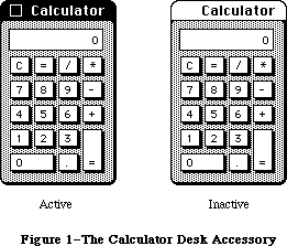 Figure 1–The Calculator Desk Accessory
The Macintosh user opens desk accessories by choosing them from the standard Apple menu (whose title is an apple symbol), which by convention is the first menu in the menu bar. When a desk accessory is chosen from this menu, it’s usually displayed in a window on the desktop, and that window becomes the active window (see Figure 2).
Figure 1–The Calculator Desk Accessory
The Macintosh user opens desk accessories by choosing them from the standard Apple menu (whose title is an apple symbol), which by convention is the first menu in the menu bar. When a desk accessory is chosen from this menu, it’s usually displayed in a window on the desktop, and that window becomes the active window (see Figure 2).
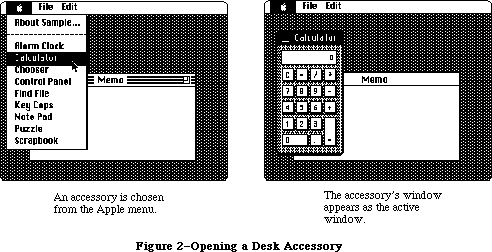 Figure 2–Opening a Desk Accessory
After being opened, the accessory may be used as long as it’s active. The user can activate other windows and then reactivate the desk accessory by clicking inside it. Whenever a standard desk accessory is active, it has a close box in its title bar. Clicking the close box (or choosing Close from the File menu) makes the accessory disappear, and the window that’s then frontmost becomes active.
X-Ref: Technical Note #5
The window associated with a desk accessory is usually a rounded-corner window
(as shown in Figure 1) or a standard document window, although it can be any type of window. It may even look and behave like a dialog window; the accessory can call on the Dialog Manager to create the window and then use Dialog Manager routines to operate on it. In any case, the window will be a system window, as indicated by the fact that its windowKind field contains a negative value.
The Desk Manager provides a mechanism that lets standard commands chosen from the Edit menu be applied to a desk accessory when it’s active. Even if the commands aren’t particularly useful for editing within the accessory, they may be useful for cutting and pasting between the accessory and the application or even another accessory. For example, the result of a calculation made with the Calculator can be copied and pasted into a document prepared in MacWrite.
A desk accessory may also have its own menu. When the accessory becomes active, the title of its menu is added to the menu bar and menu items may be chosen from it. Any of the application’s menus or menu items that no longer apply are disabled. A desk accessory can even have an entire menu bar full of its own menus, which will completely replace the menus already in the menu bar. When an accessory that has its own menu or menus becomes inactive, the menu bar is restored to normal.
Although desk accessories are usually displayed in windows (one per accessory); it’s possible for an accessory to have only a menu (or menus) and not a window. In this case, the menu includes a command to close the accessory. Also, a desk accessory that’s displayed in a window may create any number of additional windows while it’s open.
A desk accessory is actually a special type of device driver—special in that it may have its own windows and menus for interacting with the user. The value in the windowKind field of a desk accessory’s window is a reference number that uniquely identifies the driver, returned by the Device Manager when the driver was opened. Desk accessories and other RAM drivers used by Macintosh applications are stored in resource files.
_______________________________________________________________________________
»USING THE DESK MANAGER
_______________________________________________________________________________
To allow access to desk accessories, your application must do the following:
• Initialize TextEdit and the Dialog Manager, in case any desk
accessories are displayed in windows created by the Dialog Manager
(which uses TextEdit).
• Set up the Apple menu as the first menu in the menu bar. You can put
the names of all currently available desk accessories in a menu by
using the Menu Manager procedure AddResMenu.
• Set up an Edit menu that includes the standard commands Undo, Cut,
Copy, Paste, and Clear (in that order, with a dividing line between
Undo and Cut), even if your application itself doesn’t support any
of these commands.
Note: Applications should leave enough space in the menu bar for a
desk accessory’s menu to be added.
When the user chooses a desk accessory from the Apple menu, call the Menu Manager procedure GetItem to get the name of the desk accessory, and then the Desk Manager function OpenDeskAcc to open and display the accessory. When a system window is active and the user chooses Close from the File menu, close the desk accessory with the CloseDeskAcc procedure.
Warning: Most open desk accessories allocate nonrelocatable objects
(such as windows) in the heap, resulting in fragmentation of
heap space. Before beginning an operation that requires a large
amount of memory, your application may want to close all open
desk accessories (or allow the user to close some of them).
When the Toolbox Event Manager function GetNextEvent reports that a mouse-down event has occurred, your application should call the Window Manager function FindWindow to find out where the mouse button was pressed. If FindWindow returns the predefined constant inSysWindow, which means that the mouse button was pressed in a system window, call the Desk Manager procedure SystemClick. SystemClick handles mouse-down events in system windows, routing them to desk accessories where appropriate.
Note: The application needn’t be concerned with exactly which desk
accessories are currently open.
When the active window changes from an application window to a system window, the application should disable any of its menus or menu items that don’t apply while an accessory is active, and it should enable the standard editing commands Undo, Cut, Copy, Paste, and Clear, in the Edit menu. An application should disable any editing commands it doesn’t support when one of its own windows becomes active.
When a mouse-down event occurs in the menu bar, and the application determines that one of the five standard editing commands has been invoked, it should call SystemEdit. Only if SystemEdit returns FALSE should the application process the editing command itself; if the active window belongs to a desk accessory, SystemEdit passes the editing command on to that accessory and returns TRUE.
Keyboard equivalents of the standard editing commands are passed on to desk accessories by the Desk Manager, not by your application.
Warning: The standard keyboard equivalents for the commands in the Edit
menu must not be changed or assigned to other commands; the Desk
Manager automatically interprets Command-Z, X, C, and V as Undo,
Cut, Copy, and Paste, respectively.
Certain periodic actions may be defined for desk accessories. To see that
they’re performed, you need to call the SystemTask procedure at least once every time through your main event loop.
The two remaining Desk Manager routines—SystemEvent and SystemMenu—are never called by the application, but are described in this chapter because they reveal inner mechanisms of the Toolbox that may be of interest to advanced programmers.
_______________________________________________________________________________
»DESK MANAGER ROUTINES
_______________________________________________________________________________
»Opening and Closing Desk Accessories
FUNCTION OpenDeskAcc (theAcc: Str255) : INTEGER;
OpenDeskAcc opens the desk accessory having the given name and displays its window (if any) as the active window. The name is the accessory’s resource name, which you get from the Apple menu by calling the Menu Manager procedure GetItem. OpenDeskAcc calls the Resource Manager to read the desk accessory from the resource file into the application heap.
You should ignore the value returned by OpenDeskAcc. If the desk accessory is successfully opened, the function result is its driver reference number. However, if the desk accessory can’t be opened, the function result is undefined; the accessory will have taken care of informing the user of the problem (such as memory full) and won’t display itself.
Warning: Early versions of some desk accessories may set the current
grafPort to the accessory’s port upon return from OpenDeskAcc.
To be safe, you should bracket your call to OpenDeskAcc with
calls to the QuickDraw procedures GetPort and SetPort, to save
and restore the current port.
Note: Programmers concerned about the amount of available memory should
be aware that an open desk accessory uses from 1K to 3K bytes of
heap space in addition to the space needed for the accessory itself.
The desk accessory is responsible for determining whether there is
sufficient memory for it to run; this can be done by calling
SizeResource followed by ResrvMem.
PROCEDURE CloseDeskAcc (refNum: INTEGER);
When a system window is active and the user chooses Close from the File menu, call CloseDeskAcc to close the desk accessory. RefNum is the driver reference number for the desk accessory, which you get from the windowKind field of its window.
The Desk Manager automatically closes a desk accessory if the user clicks its close box. Also, since the application heap is released when the application terminates, every desk accessory goes away at that time.
_______________________________________________________________________________
»Handling Events in Desk Accessories
PROCEDURE SystemClick (theEvent: EventRecord; theWindow: WindowPtr);
When a mouse-down event occurs and the Window Manager function FindWindow reports that the mouse button was pressed in a system window, the application should call SystemClick with the event record and the window pointer. If the given window belongs to a desk accessory, SystemClick sees that the event gets handled properly.
SystemClick determines which part of the desk accessory’s window the mouse button was pressed in, and responds accordingly (similar to the way your application responds to mouse activities in its own windows).
• If the mouse button was pressed in the content region of the window
and the window was active, SystemClick sends the mouse-down event to
the desk accessory, which processes it as appropriate.
• If the mouse button was pressed in the content region and the window
was inactive, SystemClick makes it the active window.
• If the mouse button was pressed in the drag region, SystemClick calls
the Window Manager procedure DragWindow to pull an outline of the window
across the screen and move the window to a new location. If the window
was inactive, DragWindow also makes it the active window (unless the
Command key was pressed along with the mouse button).
• If the mouse button was pressed in the go-away region, SystemClick calls
the Window Manager function TrackGoAway to determine whether the mouse
is still inside the go-away region when the click is completed: If
so, it tells the desk accessory to close itself; otherwise, it does
nothing.
FUNCTION SystemEdit (editCmd: INTEGER) : BOOLEAN;
Assembly-language note: The macro you invoke to call SystemEdit from
assembly language is named _SysEdit.
Call SystemEdit when there’s a mouse-down event in the menu bar and the user chooses one of the five standard editing commands from the Edit menu. Pass one of the following as the value of the editCmd parameter:
editCmd Editing command
0 Undo
2 Cut
3 Copy
4 Paste
5 Clear
If your Edit menu contains these five commands in the standard arrangement (the order listed above, with a dividing line between Undo and Cut), you can simply call
SystemEdit(menuItem-1)
where menuItem is the menu item number.
If the active window doesn’t belong to a desk accessory, SystemEdit returns FALSE; the application should then process the editing command as usual. If the active window does belong to a desk accessory, SystemEdit asks that accessory to process the command and returns TRUE; in this case, the application should ignore the command.
Note: It’s up to the application to make sure desk accessories get
their editing commands that are chosen from the Edit menu. In
particular, make sure your application hasn’t disabled the Edit
menu or any of the five standard commands when a desk accessory
is activated.
_______________________________________________________________________________
»Performing Periodic Actions
PROCEDURE SystemTask;
For each open desk accessory (or other device driver performing periodic actions), SystemTask causes the accessory to perform the periodic action defined for it, if any such action has been defined and if the proper time period has passed since the action was last performed. For example, a clock accessory can be defined such that the second hand is to move once every second; the periodic action for the accessory will be to move the second hand to the next position, and SystemTask will alert the accessory every second to perform that action.
You should call SystemTask as often as possible, usually once every time through your main event loop. Call it more than once if your application does an unusually large amount of processing each time through the loop.
Note: SystemTask should be called at least every sixtieth of a second.
_______________________________________________________________________________
»Advanced Routines
FUNCTION SystemEvent (theEvent: EventRecord) : BOOLEAN;
SystemEvent is called only by the Toolbox Event Manager function GetNextEvent when it receives an event, to determine whether the event should be handled by the application or by the system. If the given event should be handled by the application, SystemEvent returns FALSE; otherwise, it calls the appropriate system code to handle the event and returns TRUE.
In the case of a null or mouse-down event, SystemEvent does nothing but return FALSE. Notice that it responds this way to a mouse-down event even though the event may in fact have occurred in a system window (and therefore may have to be handled by the system). The reason for this is that the check for exactly where the event occurred (via the Window Manager function FindWindow) is made later by the application and so would be made twice if SystemEvent were also to do it. To avoid this duplication, SystemEvent passes the event on to the application and lets it make the sole call to FindWindow. Should FindWindow reveal that the mouse-down event did occur in a system window, the application can then call SystemClick, as described above, to get the system to handle it.
If the given event is a mouse-up or any keyboard event (including keyboard equivalents of commands), SystemEvent checks whether the active window belongs to a desk accessory and whether that accessory can handle this type of event. If so, it sends the event to the desk accessory and returns TRUE; otherwise, it returns FALSE.
If SystemEvent is passed an activate or update event, it checks whether the window the event occurred in is a system window belonging to a desk accessory and whether that accessory can handle this type of event. If so, it sends the event to the desk accessory and returns TRUE; otherwise, it returns FALSE.
Note: It’s unlikely that a desk accessory would not be set up to handle
keyboard, activate, and update events, or that it would handle
mouse-up events.
If the given event is a disk-inserted event, SystemEvent does some
low-level processing (by calling the File Manager function MountVol)
but passes the event on to the application by returning FALSE, in
case the application wants to do further processing. Finally,
SystemEvent returns FALSE for network, device driver, and
application-defined events.
Assembly-language note: Advanced programmers can make SystemEvent
always return FALSE by setting the global
variable SEvtEnb (a byte) to 0.
PROCEDURE SystemMenu (menuResult: LONGINT);
SystemMenu is called only by the Menu Manager functions MenuSelect and MenuKey, when an item in a menu belonging to a desk accessory has been chosen. The menuResult parameter has the same format as the value returned by MenuSelect and MenuKey: the menu ID in the high-order word and the menu item number in the low-order word. (The menu ID will be negative.) SystemMenu directs the desk accessory to perform the appropriate action for the given menu item.
_______________________________________________________________________________
»WRITING YOUR OWN DESK ACCESSORIES
_______________________________________________________________________________
To write your own desk accessory, you must create it as a device driver and include it in a resource file, as described in the Device Manager chapter. Standard or shared desk accessories are stored in the system resource file. Accessories specific to an application are rare; if there are any, they’re stored in the application’s resource file.
The resource type for a device driver is 'DRVR'. The resource ID for a desk accessory is the driver’s unit number and must be between 12 and 31 inclusive.
Note: A desk accessory will often have additional resources (such as
pattern and string resources) that are associated with it. These
resources must observe a special numbering convention, as described
in the Resource Manager chapter.
The resource name should be whatever you want to appear in the Apple menu, but should also include a nonprinting character; by convention, the name should begin with a NUL character (ASCII code 0). The nonprinting character is needed to avoid conflict with file names that are the same as the names of desk accessories.
Device drivers are usually written in assembly language. The structure of a device driver is described in the Device Manager chapter. The rest of this section reviews some of that information and presents additional details pertaining specifically to device drivers that are desk accessories.
As shown in Figure 3, a device driver begins with a few words of flags and other data, followed by offsets to the routines that do the work of the driver, an optional title, and finally the routines themselves.
Figure 2–Opening a Desk Accessory
After being opened, the accessory may be used as long as it’s active. The user can activate other windows and then reactivate the desk accessory by clicking inside it. Whenever a standard desk accessory is active, it has a close box in its title bar. Clicking the close box (or choosing Close from the File menu) makes the accessory disappear, and the window that’s then frontmost becomes active.
X-Ref: Technical Note #5
The window associated with a desk accessory is usually a rounded-corner window
(as shown in Figure 1) or a standard document window, although it can be any type of window. It may even look and behave like a dialog window; the accessory can call on the Dialog Manager to create the window and then use Dialog Manager routines to operate on it. In any case, the window will be a system window, as indicated by the fact that its windowKind field contains a negative value.
The Desk Manager provides a mechanism that lets standard commands chosen from the Edit menu be applied to a desk accessory when it’s active. Even if the commands aren’t particularly useful for editing within the accessory, they may be useful for cutting and pasting between the accessory and the application or even another accessory. For example, the result of a calculation made with the Calculator can be copied and pasted into a document prepared in MacWrite.
A desk accessory may also have its own menu. When the accessory becomes active, the title of its menu is added to the menu bar and menu items may be chosen from it. Any of the application’s menus or menu items that no longer apply are disabled. A desk accessory can even have an entire menu bar full of its own menus, which will completely replace the menus already in the menu bar. When an accessory that has its own menu or menus becomes inactive, the menu bar is restored to normal.
Although desk accessories are usually displayed in windows (one per accessory); it’s possible for an accessory to have only a menu (or menus) and not a window. In this case, the menu includes a command to close the accessory. Also, a desk accessory that’s displayed in a window may create any number of additional windows while it’s open.
A desk accessory is actually a special type of device driver—special in that it may have its own windows and menus for interacting with the user. The value in the windowKind field of a desk accessory’s window is a reference number that uniquely identifies the driver, returned by the Device Manager when the driver was opened. Desk accessories and other RAM drivers used by Macintosh applications are stored in resource files.
_______________________________________________________________________________
»USING THE DESK MANAGER
_______________________________________________________________________________
To allow access to desk accessories, your application must do the following:
• Initialize TextEdit and the Dialog Manager, in case any desk
accessories are displayed in windows created by the Dialog Manager
(which uses TextEdit).
• Set up the Apple menu as the first menu in the menu bar. You can put
the names of all currently available desk accessories in a menu by
using the Menu Manager procedure AddResMenu.
• Set up an Edit menu that includes the standard commands Undo, Cut,
Copy, Paste, and Clear (in that order, with a dividing line between
Undo and Cut), even if your application itself doesn’t support any
of these commands.
Note: Applications should leave enough space in the menu bar for a
desk accessory’s menu to be added.
When the user chooses a desk accessory from the Apple menu, call the Menu Manager procedure GetItem to get the name of the desk accessory, and then the Desk Manager function OpenDeskAcc to open and display the accessory. When a system window is active and the user chooses Close from the File menu, close the desk accessory with the CloseDeskAcc procedure.
Warning: Most open desk accessories allocate nonrelocatable objects
(such as windows) in the heap, resulting in fragmentation of
heap space. Before beginning an operation that requires a large
amount of memory, your application may want to close all open
desk accessories (or allow the user to close some of them).
When the Toolbox Event Manager function GetNextEvent reports that a mouse-down event has occurred, your application should call the Window Manager function FindWindow to find out where the mouse button was pressed. If FindWindow returns the predefined constant inSysWindow, which means that the mouse button was pressed in a system window, call the Desk Manager procedure SystemClick. SystemClick handles mouse-down events in system windows, routing them to desk accessories where appropriate.
Note: The application needn’t be concerned with exactly which desk
accessories are currently open.
When the active window changes from an application window to a system window, the application should disable any of its menus or menu items that don’t apply while an accessory is active, and it should enable the standard editing commands Undo, Cut, Copy, Paste, and Clear, in the Edit menu. An application should disable any editing commands it doesn’t support when one of its own windows becomes active.
When a mouse-down event occurs in the menu bar, and the application determines that one of the five standard editing commands has been invoked, it should call SystemEdit. Only if SystemEdit returns FALSE should the application process the editing command itself; if the active window belongs to a desk accessory, SystemEdit passes the editing command on to that accessory and returns TRUE.
Keyboard equivalents of the standard editing commands are passed on to desk accessories by the Desk Manager, not by your application.
Warning: The standard keyboard equivalents for the commands in the Edit
menu must not be changed or assigned to other commands; the Desk
Manager automatically interprets Command-Z, X, C, and V as Undo,
Cut, Copy, and Paste, respectively.
Certain periodic actions may be defined for desk accessories. To see that
they’re performed, you need to call the SystemTask procedure at least once every time through your main event loop.
The two remaining Desk Manager routines—SystemEvent and SystemMenu—are never called by the application, but are described in this chapter because they reveal inner mechanisms of the Toolbox that may be of interest to advanced programmers.
_______________________________________________________________________________
»DESK MANAGER ROUTINES
_______________________________________________________________________________
»Opening and Closing Desk Accessories
FUNCTION OpenDeskAcc (theAcc: Str255) : INTEGER;
OpenDeskAcc opens the desk accessory having the given name and displays its window (if any) as the active window. The name is the accessory’s resource name, which you get from the Apple menu by calling the Menu Manager procedure GetItem. OpenDeskAcc calls the Resource Manager to read the desk accessory from the resource file into the application heap.
You should ignore the value returned by OpenDeskAcc. If the desk accessory is successfully opened, the function result is its driver reference number. However, if the desk accessory can’t be opened, the function result is undefined; the accessory will have taken care of informing the user of the problem (such as memory full) and won’t display itself.
Warning: Early versions of some desk accessories may set the current
grafPort to the accessory’s port upon return from OpenDeskAcc.
To be safe, you should bracket your call to OpenDeskAcc with
calls to the QuickDraw procedures GetPort and SetPort, to save
and restore the current port.
Note: Programmers concerned about the amount of available memory should
be aware that an open desk accessory uses from 1K to 3K bytes of
heap space in addition to the space needed for the accessory itself.
The desk accessory is responsible for determining whether there is
sufficient memory for it to run; this can be done by calling
SizeResource followed by ResrvMem.
PROCEDURE CloseDeskAcc (refNum: INTEGER);
When a system window is active and the user chooses Close from the File menu, call CloseDeskAcc to close the desk accessory. RefNum is the driver reference number for the desk accessory, which you get from the windowKind field of its window.
The Desk Manager automatically closes a desk accessory if the user clicks its close box. Also, since the application heap is released when the application terminates, every desk accessory goes away at that time.
_______________________________________________________________________________
»Handling Events in Desk Accessories
PROCEDURE SystemClick (theEvent: EventRecord; theWindow: WindowPtr);
When a mouse-down event occurs and the Window Manager function FindWindow reports that the mouse button was pressed in a system window, the application should call SystemClick with the event record and the window pointer. If the given window belongs to a desk accessory, SystemClick sees that the event gets handled properly.
SystemClick determines which part of the desk accessory’s window the mouse button was pressed in, and responds accordingly (similar to the way your application responds to mouse activities in its own windows).
• If the mouse button was pressed in the content region of the window
and the window was active, SystemClick sends the mouse-down event to
the desk accessory, which processes it as appropriate.
• If the mouse button was pressed in the content region and the window
was inactive, SystemClick makes it the active window.
• If the mouse button was pressed in the drag region, SystemClick calls
the Window Manager procedure DragWindow to pull an outline of the window
across the screen and move the window to a new location. If the window
was inactive, DragWindow also makes it the active window (unless the
Command key was pressed along with the mouse button).
• If the mouse button was pressed in the go-away region, SystemClick calls
the Window Manager function TrackGoAway to determine whether the mouse
is still inside the go-away region when the click is completed: If
so, it tells the desk accessory to close itself; otherwise, it does
nothing.
FUNCTION SystemEdit (editCmd: INTEGER) : BOOLEAN;
Assembly-language note: The macro you invoke to call SystemEdit from
assembly language is named _SysEdit.
Call SystemEdit when there’s a mouse-down event in the menu bar and the user chooses one of the five standard editing commands from the Edit menu. Pass one of the following as the value of the editCmd parameter:
editCmd Editing command
0 Undo
2 Cut
3 Copy
4 Paste
5 Clear
If your Edit menu contains these five commands in the standard arrangement (the order listed above, with a dividing line between Undo and Cut), you can simply call
SystemEdit(menuItem-1)
where menuItem is the menu item number.
If the active window doesn’t belong to a desk accessory, SystemEdit returns FALSE; the application should then process the editing command as usual. If the active window does belong to a desk accessory, SystemEdit asks that accessory to process the command and returns TRUE; in this case, the application should ignore the command.
Note: It’s up to the application to make sure desk accessories get
their editing commands that are chosen from the Edit menu. In
particular, make sure your application hasn’t disabled the Edit
menu or any of the five standard commands when a desk accessory
is activated.
_______________________________________________________________________________
»Performing Periodic Actions
PROCEDURE SystemTask;
For each open desk accessory (or other device driver performing periodic actions), SystemTask causes the accessory to perform the periodic action defined for it, if any such action has been defined and if the proper time period has passed since the action was last performed. For example, a clock accessory can be defined such that the second hand is to move once every second; the periodic action for the accessory will be to move the second hand to the next position, and SystemTask will alert the accessory every second to perform that action.
You should call SystemTask as often as possible, usually once every time through your main event loop. Call it more than once if your application does an unusually large amount of processing each time through the loop.
Note: SystemTask should be called at least every sixtieth of a second.
_______________________________________________________________________________
»Advanced Routines
FUNCTION SystemEvent (theEvent: EventRecord) : BOOLEAN;
SystemEvent is called only by the Toolbox Event Manager function GetNextEvent when it receives an event, to determine whether the event should be handled by the application or by the system. If the given event should be handled by the application, SystemEvent returns FALSE; otherwise, it calls the appropriate system code to handle the event and returns TRUE.
In the case of a null or mouse-down event, SystemEvent does nothing but return FALSE. Notice that it responds this way to a mouse-down event even though the event may in fact have occurred in a system window (and therefore may have to be handled by the system). The reason for this is that the check for exactly where the event occurred (via the Window Manager function FindWindow) is made later by the application and so would be made twice if SystemEvent were also to do it. To avoid this duplication, SystemEvent passes the event on to the application and lets it make the sole call to FindWindow. Should FindWindow reveal that the mouse-down event did occur in a system window, the application can then call SystemClick, as described above, to get the system to handle it.
If the given event is a mouse-up or any keyboard event (including keyboard equivalents of commands), SystemEvent checks whether the active window belongs to a desk accessory and whether that accessory can handle this type of event. If so, it sends the event to the desk accessory and returns TRUE; otherwise, it returns FALSE.
If SystemEvent is passed an activate or update event, it checks whether the window the event occurred in is a system window belonging to a desk accessory and whether that accessory can handle this type of event. If so, it sends the event to the desk accessory and returns TRUE; otherwise, it returns FALSE.
Note: It’s unlikely that a desk accessory would not be set up to handle
keyboard, activate, and update events, or that it would handle
mouse-up events.
If the given event is a disk-inserted event, SystemEvent does some
low-level processing (by calling the File Manager function MountVol)
but passes the event on to the application by returning FALSE, in
case the application wants to do further processing. Finally,
SystemEvent returns FALSE for network, device driver, and
application-defined events.
Assembly-language note: Advanced programmers can make SystemEvent
always return FALSE by setting the global
variable SEvtEnb (a byte) to 0.
PROCEDURE SystemMenu (menuResult: LONGINT);
SystemMenu is called only by the Menu Manager functions MenuSelect and MenuKey, when an item in a menu belonging to a desk accessory has been chosen. The menuResult parameter has the same format as the value returned by MenuSelect and MenuKey: the menu ID in the high-order word and the menu item number in the low-order word. (The menu ID will be negative.) SystemMenu directs the desk accessory to perform the appropriate action for the given menu item.
_______________________________________________________________________________
»WRITING YOUR OWN DESK ACCESSORIES
_______________________________________________________________________________
To write your own desk accessory, you must create it as a device driver and include it in a resource file, as described in the Device Manager chapter. Standard or shared desk accessories are stored in the system resource file. Accessories specific to an application are rare; if there are any, they’re stored in the application’s resource file.
The resource type for a device driver is 'DRVR'. The resource ID for a desk accessory is the driver’s unit number and must be between 12 and 31 inclusive.
Note: A desk accessory will often have additional resources (such as
pattern and string resources) that are associated with it. These
resources must observe a special numbering convention, as described
in the Resource Manager chapter.
The resource name should be whatever you want to appear in the Apple menu, but should also include a nonprinting character; by convention, the name should begin with a NUL character (ASCII code 0). The nonprinting character is needed to avoid conflict with file names that are the same as the names of desk accessories.
Device drivers are usually written in assembly language. The structure of a device driver is described in the Device Manager chapter. The rest of this section reviews some of that information and presents additional details pertaining specifically to device drivers that are desk accessories.
As shown in Figure 3, a device driver begins with a few words of flags and other data, followed by offsets to the routines that do the work of the driver, an optional title, and finally the routines themselves.
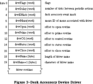 Figure 3–Desk Accessory Device Driver
One bit in the high-order byte of the drvrFlags word is frequently used by desk accessories:
dNeedTime .EQU 5 ; set if driver needs time for performing
; a periodic action
Desk accessories may need to perform predefined actions periodically. For example, a clock desk accessory may want to change the time it displays every second. If the dNeedTime flag is set, the desk accessory does need to perform a periodic action, and the drvrDelay word contains a tick count indicating how often the periodic action should occur. Whether the action actually occurs as frequently as specified depends on how often the application calls the Desk Manager procedure SystemTask. SystemTask calls the desk accessory’s control routine (if the time indicated by drvrDelay has elapsed), and the control routine must perform whatever predefined action is desired.
Note: A desk accessory cannot rely on SystemTask being called regularly
or frequently by an application. If it needs precise timing it
should install a task to be executed during the vertical retrace
interrupt. There are, however, certain restrictions on tasks
performed during interrupts, such as not being able to make calls
to the Memory Manager. For more information on these restrictions,
see the Vertical Retrace Manager chapter. Periodic actions performed
in response to SystemTask calls are not performed via an interrupt
and so don’t have these restrictions.
The drvrEMask word contains an event mask specifying which events the desk accessory can handle. If the accessory has a window, the mask should include keyboard, activate, update, and mouse-down events, but must not include mouse-up events.
Note: The accessory may not be interested in keyboard input, but it
should still respond to key-down and auto-key events, at least
with a beep.
When an event occurs, the Toolbox Event Manager calls SystemEvent. SystemEvent checks the drvrEMask word to determine whether the desk accessory can handle the type of event, and if so, calls the desk accessory’s control routine. The control routine must perform whatever action is desired.
If the desk accessory has its own menu (or menus), the drvrMenu word contains the menu ID of the menu (or of any one of the menus); otherwise, it contains 0. The menu ID for a desk accessory menu must be negative, and it must be different from the menu ID stored in other desk accessories.
Following these four words are the offsets to the driver routines and, optionally, a title for the desk accessory (preceded by its length in bytes). You can use the title in the driver as the title of the accessory’s window, or just as a way of identifying the driver in memory.
Note: A practical size limit for desk accessories is about 8K bytes.
_______________________________________________________________________________
»The Driver Routines
Of the five possible driver routines, only three need to exist for desk accessories: the open, close, and control routines. The other routines (prime and status) may be used if desired for a particular accessory.
The open routine opens the desk accessory:
• It creates the window to be displayed when the accessory is opened,
if any, specifying that it be invisible (since OpenDeskAcc will
display it). The window can be created with the Dialog Manager
function GetNewDialog (or NewDialog) if desired; the accessory
will look and respond like a dialog box, and subsequent operations
may be performed on it with Dialog Manager routines. In any case,
the open routine sets the windowKind field of the window record to
the driver reference number for the desk accessory, which it gets
from the device control entry. (The reference number will be negative.)
It also stores the window pointer in the device control entry.
• If the driver has any private storage, it allocates the storage,
stores a handle to it in the device control entry, and initializes
any local variables. It might, for example, create a menu or menus
for the accessory.
If the open routine is unable to complete all of the above tasks (if it runs out of memory, for example), it must do the following:
• Open only the minimum of data structures needed to run the desk accessory.
• Modify the code of every routine (except the close routine) so that
the routine just returns (or beeps) when called.
• Modify the code of the close routine so that it disposes of only the
minimum data structures that were opened.
• Display an alert indicating failure, such as “The Note Pad is not
available”.
The close routine closes the desk accessory, disposing of its window (if any) and all the data structures associated with it and replacing the window pointer in the device control entry with NIL. If the driver has any private storage, the close routine also disposes of that storage.
Warning: A driver’s private storage shouldn’t be in the system heap,
because the application heap is reinitialized when an application
terminates, and the driver is lost before it can dispose of its
storage.
The action taken by the control routine depends on information passed in the parameter block pointed to by register A0. A message is passed in the csCode parameter; this message is simply a number that tells the routine what action to take. There are nine such messages:
accEvent .EQU 64 ;handle a given event
accRun .EQU 65 ;take the periodic action, if any,
; for this desk accessory
accCursor .EQU 66 ;change cursor shape if appropriate; generate
; null event if window was created by Dialog Manager
accMenu .EQU 67 ;handle a given menu item
accUndo .EQU 68 ;handle the Undo command
accCut .EQU 70 ;handle the Cut command
accCopy .EQU 71 ;handle the Copy command
accPaste .EQU 72 ;handle the Paste command
accClear .EQU 73 ;handle the Clear command
Note: As described in the Device Manager chapter, the control routine
may also receive the message goodBye in the csCode parameter telling
it when the heap is about to be reinitialized.
Along with the accEvent message, the control routine receives in the csParam field a pointer to an event record. The control routine must respond by handling the given event in whatever way is appropriate for this desk accessory. SystemClick and SystemEvent call the control routine with this message to send the driver an event that it should handle—for example, an activate event that makes the desk accessory active or inactive. When a desk accessory becomes active, its control routine might install a menu in the menu bar. If the accessory becoming active has more than one menu, the control routine should respond as follows:
• Store the accessory’s unique menu ID in the global variable
MBarEnable. (This is the negative menu ID in the device driver
and the device control entry.)
• Call the Menu Manager routines GetMenuBar to save the current
menu list and ClearMenuBar to clear the menu bar.
• Install the accessory’s own menus in the menu bar.
Then, when the desk accessory becomes inactive, the control routine should call SetMenuBar to restore the former menu list, call DrawMenuBar to draw the menu bar, and set MBarEnable to 0.
The accRun message tells the control routine to perform the periodic action for this desk accessory. For every open driver that has the dNeedTime flag set, the SystemTask procedure calls the control routine with this message if the proper time period has passed since the action was last performed.
The accCursor message makes it possible to change the shape of the cursor when it’s inside an active desk accessory. SystemTask calls the control routine with this message as long as the desk accessory is active. The control routine should respond by checking whether the mouse location is in the desk
accessory’s window; if it is, it should set it to the standard arrow cursor (by calling the QuickDraw procedure InitCursor), just in case the application has changed the cursor and failed to reset it. Or, if desired, your accessory may give the cursor a special shape (by calling the QuickDraw procedure SetCursor).
If the desk accessory is displayed in a window created by the Dialog Manager, the control routine should respond to the accCursor message by generating a null event (storing the event code for a null event in an event record) and passing it to DialogSelect. This enables the Dialog Manager to blink the caret in editText items. In assembly language, the code might look like this:
CLR.L -(SP) ;event code for null event is 0
PEA 2(SP) ;pass null event
CLR.L -(SP) ;pass NIL dialog pointer
CLR.L -(SP) ;pass NIL pointer
_DialogSelect ;invoke DialogSelect
ADDQ.L #4,SP ;pop off result and null event
When the accMenu message is sent to the control routine, the following information is passed in the parameter block: csParam contains the menu ID of the desk accessory’s menu and csParam+2 contains the menu item number. The control routine should take the appropriate action for when the given menu item is chosen from the menu, and then make the Menu Manager call HiliteMenu(0) to remove the highlighting from the menu bar.
Finally, the control routine should respond to one of the last five messages—accUndo through accClear—by processing the corresponding editing command in the desk accessory window if appropriate. SystemEdit calls the control routine with these messages. For information on cutting and pasting between a desk accessory and the application, or between two desk accessories, see the Scrap Manager chapter.
Warning: If the accessory opens a resource file, or otherwise changes
which file is the current resource file, it should save and
restore the previous current resource file, using the Resource
Manager routines CurResFile and UseResFile. Similarly, the
accessory should save and restore the port that was the current
grafPort, using the QuickDraw routines GetPort and SetPort.
_______________________________________________________________________________
»SUMMARY OF THE DESK MANAGER
_______________________________________________________________________________
Routines
Opening and Closing Desk Accessories
FUNCTION OpenDeskAcc (theAcc: Str255) : INTEGER;
PROCEDURE CloseDeskAcc (refNum: INTEGER);
Handling Events in Desk Accessories
PROCEDURE SystemClick (theEvent: EventRecord; theWindow: WindowPtr);
FUNCTION SystemEdit (editCmd: INTEGER) : BOOLEAN;
Performing Periodic Actions
PROCEDURE SystemTask;
Advanced Routines
FUNCTION SystemEvent (theEvent: EventRecord) : BOOLEAN;
PROCEDURE SystemMenu (menuResult: LONGINT);
_______________________________________________________________________________
Assembly-Language Information
Constants
; Desk accessory flag
dNeedTime .EQU 5 ; set if driver needs time for performing
; a periodic action
; Control routine messages
accEvent .EQU 64 ;handle a given event
accRun .EQU 65 ;take the periodic action, if any,
; for this desk accessory
accCursor .EQU 66 ;change cursor shape if appropriate; generate
; null event if window was created by Dialog Manager
accMenu .EQU 67 ;handle a given menu item
accUndo .EQU 68 ;handle the Undo command
accCut .EQU 70 ;handle the Cut command
accCopy .EQU 71 ;handle the Copy command
accPaste .EQU 72 ;handle the Paste command
accClear .EQU 73 ;handle the Clear command
Special Macro Names
Pascal name Macro name
SystemEdit _SysEdit
Variables
MBarEnable Unique menu ID for active desk accessory, when menu bar
belongs to the accessory (word)
SEvtEnb 0 if SystemEvent should return FALSE (byte)
Further Reference:
_______________________________________________________________________________
Resource Manager
QuickDraw
Toolbox Event Manager
Window Manager
Menu Manager
Device Manager
Technical Note #5, Using Modeless Dialogs from Desk Accessories
Technical Note #85, GetNextEvent; Blinking Apple Menu
Figure 3–Desk Accessory Device Driver
One bit in the high-order byte of the drvrFlags word is frequently used by desk accessories:
dNeedTime .EQU 5 ; set if driver needs time for performing
; a periodic action
Desk accessories may need to perform predefined actions periodically. For example, a clock desk accessory may want to change the time it displays every second. If the dNeedTime flag is set, the desk accessory does need to perform a periodic action, and the drvrDelay word contains a tick count indicating how often the periodic action should occur. Whether the action actually occurs as frequently as specified depends on how often the application calls the Desk Manager procedure SystemTask. SystemTask calls the desk accessory’s control routine (if the time indicated by drvrDelay has elapsed), and the control routine must perform whatever predefined action is desired.
Note: A desk accessory cannot rely on SystemTask being called regularly
or frequently by an application. If it needs precise timing it
should install a task to be executed during the vertical retrace
interrupt. There are, however, certain restrictions on tasks
performed during interrupts, such as not being able to make calls
to the Memory Manager. For more information on these restrictions,
see the Vertical Retrace Manager chapter. Periodic actions performed
in response to SystemTask calls are not performed via an interrupt
and so don’t have these restrictions.
The drvrEMask word contains an event mask specifying which events the desk accessory can handle. If the accessory has a window, the mask should include keyboard, activate, update, and mouse-down events, but must not include mouse-up events.
Note: The accessory may not be interested in keyboard input, but it
should still respond to key-down and auto-key events, at least
with a beep.
When an event occurs, the Toolbox Event Manager calls SystemEvent. SystemEvent checks the drvrEMask word to determine whether the desk accessory can handle the type of event, and if so, calls the desk accessory’s control routine. The control routine must perform whatever action is desired.
If the desk accessory has its own menu (or menus), the drvrMenu word contains the menu ID of the menu (or of any one of the menus); otherwise, it contains 0. The menu ID for a desk accessory menu must be negative, and it must be different from the menu ID stored in other desk accessories.
Following these four words are the offsets to the driver routines and, optionally, a title for the desk accessory (preceded by its length in bytes). You can use the title in the driver as the title of the accessory’s window, or just as a way of identifying the driver in memory.
Note: A practical size limit for desk accessories is about 8K bytes.
_______________________________________________________________________________
»The Driver Routines
Of the five possible driver routines, only three need to exist for desk accessories: the open, close, and control routines. The other routines (prime and status) may be used if desired for a particular accessory.
The open routine opens the desk accessory:
• It creates the window to be displayed when the accessory is opened,
if any, specifying that it be invisible (since OpenDeskAcc will
display it). The window can be created with the Dialog Manager
function GetNewDialog (or NewDialog) if desired; the accessory
will look and respond like a dialog box, and subsequent operations
may be performed on it with Dialog Manager routines. In any case,
the open routine sets the windowKind field of the window record to
the driver reference number for the desk accessory, which it gets
from the device control entry. (The reference number will be negative.)
It also stores the window pointer in the device control entry.
• If the driver has any private storage, it allocates the storage,
stores a handle to it in the device control entry, and initializes
any local variables. It might, for example, create a menu or menus
for the accessory.
If the open routine is unable to complete all of the above tasks (if it runs out of memory, for example), it must do the following:
• Open only the minimum of data structures needed to run the desk accessory.
• Modify the code of every routine (except the close routine) so that
the routine just returns (or beeps) when called.
• Modify the code of the close routine so that it disposes of only the
minimum data structures that were opened.
• Display an alert indicating failure, such as “The Note Pad is not
available”.
The close routine closes the desk accessory, disposing of its window (if any) and all the data structures associated with it and replacing the window pointer in the device control entry with NIL. If the driver has any private storage, the close routine also disposes of that storage.
Warning: A driver’s private storage shouldn’t be in the system heap,
because the application heap is reinitialized when an application
terminates, and the driver is lost before it can dispose of its
storage.
The action taken by the control routine depends on information passed in the parameter block pointed to by register A0. A message is passed in the csCode parameter; this message is simply a number that tells the routine what action to take. There are nine such messages:
accEvent .EQU 64 ;handle a given event
accRun .EQU 65 ;take the periodic action, if any,
; for this desk accessory
accCursor .EQU 66 ;change cursor shape if appropriate; generate
; null event if window was created by Dialog Manager
accMenu .EQU 67 ;handle a given menu item
accUndo .EQU 68 ;handle the Undo command
accCut .EQU 70 ;handle the Cut command
accCopy .EQU 71 ;handle the Copy command
accPaste .EQU 72 ;handle the Paste command
accClear .EQU 73 ;handle the Clear command
Note: As described in the Device Manager chapter, the control routine
may also receive the message goodBye in the csCode parameter telling
it when the heap is about to be reinitialized.
Along with the accEvent message, the control routine receives in the csParam field a pointer to an event record. The control routine must respond by handling the given event in whatever way is appropriate for this desk accessory. SystemClick and SystemEvent call the control routine with this message to send the driver an event that it should handle—for example, an activate event that makes the desk accessory active or inactive. When a desk accessory becomes active, its control routine might install a menu in the menu bar. If the accessory becoming active has more than one menu, the control routine should respond as follows:
• Store the accessory’s unique menu ID in the global variable
MBarEnable. (This is the negative menu ID in the device driver
and the device control entry.)
• Call the Menu Manager routines GetMenuBar to save the current
menu list and ClearMenuBar to clear the menu bar.
• Install the accessory’s own menus in the menu bar.
Then, when the desk accessory becomes inactive, the control routine should call SetMenuBar to restore the former menu list, call DrawMenuBar to draw the menu bar, and set MBarEnable to 0.
The accRun message tells the control routine to perform the periodic action for this desk accessory. For every open driver that has the dNeedTime flag set, the SystemTask procedure calls the control routine with this message if the proper time period has passed since the action was last performed.
The accCursor message makes it possible to change the shape of the cursor when it’s inside an active desk accessory. SystemTask calls the control routine with this message as long as the desk accessory is active. The control routine should respond by checking whether the mouse location is in the desk
accessory’s window; if it is, it should set it to the standard arrow cursor (by calling the QuickDraw procedure InitCursor), just in case the application has changed the cursor and failed to reset it. Or, if desired, your accessory may give the cursor a special shape (by calling the QuickDraw procedure SetCursor).
If the desk accessory is displayed in a window created by the Dialog Manager, the control routine should respond to the accCursor message by generating a null event (storing the event code for a null event in an event record) and passing it to DialogSelect. This enables the Dialog Manager to blink the caret in editText items. In assembly language, the code might look like this:
CLR.L -(SP) ;event code for null event is 0
PEA 2(SP) ;pass null event
CLR.L -(SP) ;pass NIL dialog pointer
CLR.L -(SP) ;pass NIL pointer
_DialogSelect ;invoke DialogSelect
ADDQ.L #4,SP ;pop off result and null event
When the accMenu message is sent to the control routine, the following information is passed in the parameter block: csParam contains the menu ID of the desk accessory’s menu and csParam+2 contains the menu item number. The control routine should take the appropriate action for when the given menu item is chosen from the menu, and then make the Menu Manager call HiliteMenu(0) to remove the highlighting from the menu bar.
Finally, the control routine should respond to one of the last five messages—accUndo through accClear—by processing the corresponding editing command in the desk accessory window if appropriate. SystemEdit calls the control routine with these messages. For information on cutting and pasting between a desk accessory and the application, or between two desk accessories, see the Scrap Manager chapter.
Warning: If the accessory opens a resource file, or otherwise changes
which file is the current resource file, it should save and
restore the previous current resource file, using the Resource
Manager routines CurResFile and UseResFile. Similarly, the
accessory should save and restore the port that was the current
grafPort, using the QuickDraw routines GetPort and SetPort.
_______________________________________________________________________________
»SUMMARY OF THE DESK MANAGER
_______________________________________________________________________________
Routines
Opening and Closing Desk Accessories
FUNCTION OpenDeskAcc (theAcc: Str255) : INTEGER;
PROCEDURE CloseDeskAcc (refNum: INTEGER);
Handling Events in Desk Accessories
PROCEDURE SystemClick (theEvent: EventRecord; theWindow: WindowPtr);
FUNCTION SystemEdit (editCmd: INTEGER) : BOOLEAN;
Performing Periodic Actions
PROCEDURE SystemTask;
Advanced Routines
FUNCTION SystemEvent (theEvent: EventRecord) : BOOLEAN;
PROCEDURE SystemMenu (menuResult: LONGINT);
_______________________________________________________________________________
Assembly-Language Information
Constants
; Desk accessory flag
dNeedTime .EQU 5 ; set if driver needs time for performing
; a periodic action
; Control routine messages
accEvent .EQU 64 ;handle a given event
accRun .EQU 65 ;take the periodic action, if any,
; for this desk accessory
accCursor .EQU 66 ;change cursor shape if appropriate; generate
; null event if window was created by Dialog Manager
accMenu .EQU 67 ;handle a given menu item
accUndo .EQU 68 ;handle the Undo command
accCut .EQU 70 ;handle the Cut command
accCopy .EQU 71 ;handle the Copy command
accPaste .EQU 72 ;handle the Paste command
accClear .EQU 73 ;handle the Clear command
Special Macro Names
Pascal name Macro name
SystemEdit _SysEdit
Variables
MBarEnable Unique menu ID for active desk accessory, when menu bar
belongs to the accessory (word)
SEvtEnb 0 if SystemEvent should return FALSE (byte)
Further Reference:
_______________________________________________________________________________
Resource Manager
QuickDraw
Toolbox Event Manager
Window Manager
Menu Manager
Device Manager
Technical Note #5, Using Modeless Dialogs from Desk Accessories
Technical Note #85, GetNextEvent; Blinking Apple Menu
The Device Manager
_______________________________________________________________________________
THE DEVICE MANAGER
_______________________________________________________________________________
About This Chapter
About the Device Manager
Using the Device Manager
Device Manager Routines
High-Level Device Manager Routines
Low-Level Device Manager Routines
Routine Parameters
Routine Descriptions
The Structure of a Device Driver
Device Control Entry
The Driver I/O Queue
The Unit Table
Writing Your Own Device Drivers
Routines for Writing Drivers
Interrupts
Level-1 (VIA) Interrupts
Level-2 (SCC) Interrupts
Writing Your Own Interrupt Handlers
The Chooser
The Device Package
Communication with the Chooser
The NewSelMsg Parameter
The FillListMsg Parameter
The GetSelMsg Parameter
The SelectMsg Parameter
The DeselectMsg Parameter
The TerminateMsg Parameter
The ButtonMsg Parameter
Operation of the Chooser
Writing a Device Driver to Run Under Chooser
Chooser Changes
Buttons
List Definition Procedure
Page Setup
Device Package Function
The Startup Process
Automatic Driver Installation
Opening Slot Devices
Slot Device Interrupts
New Routines
Summary of the Device Manager
_______________________________________________________________________________
»ABOUT THIS CHAPTER
_______________________________________________________________________________
This chapter describes the Device Manager, the part of the Operating System that controls the exchange of information between a Macintosh application and devices. It gives general information about using and writing device drivers, and also discusses interrupts: how the Macintosh uses them and how you can use them if you’re writing your own device driver.
Note: Specific information about the standard Macintosh drivers is
contained in separate chapters.
You should already be familiar with resources, as discussed in the Resource Manager section.
_______________________________________________________________________________
»ABOUT THE DEVICE MANAGER
_______________________________________________________________________________
Note: The extensions to the Device Manager described in this chapter were
originally documented in Inside Macintosh, Volumes IV and V. As such,
the Volume IV information refers to the 128K ROM and System file
version 3.2 and later, while the Volume V information refers to the
Macintosh SE and Macintosh II ROMs and System file version 4.1 and
later. The sections of this chapter that cover these extensions are
so noted.
The Device Manager is the part of the Operating System that handles communication between applications and devices. A device is a part of the Macintosh, or a piece of external equipment, that can transfer information into or out of the Macintosh. Macintosh devices include disk drives, two serial communications ports, and printers.
Note: The display screen is not a device; drawing on the screen is
handled by QuickDraw.
There are two kinds of devices: character devices and block devices. A character device reads or writes a stream of characters, or bytes, one at a time: It can neither skip bytes nor go back to a previous byte. A character device is used to get information from or send information to the world outside of the Operating System and memory: It can be an input device, an output device, or an input/output device. The serial ports and printers are all character devices.
A block device reads and writes blocks of bytes at a time; it can read or write any accessible block on demand. Block devices are usually used to store and retrieve information; for example, disk drives are block devices.
Applications communicate with devices through the Device Manager—either directly or indirectly (through another part of the Operating System or
Toolbox). For example, an application can communicate with a disk drive directly via the Device Manager, or indirectly via the File Manager (which calls the Device Manager). The Device Manager doesn’t manipulate devices directly; it calls device drivers that do (see Figure 1). Device drivers are programs that take data coming from the Device Manager and convert them into actions of devices, or convert device actions into data for the Device Manager to process.
The Operating System includes three standard device drivers in ROM: the Disk Driver, the Sound Driver, and the ROM Serial Driver. There are also a number of standard RAM drivers, including the Printer Driver, the RAM Serial Driver, the AppleTalk drivers, and desk accessories. RAM drivers are resources, and are read from the system resource file as needed.
You can add other drivers independently or build on top of the existing drivers (for example, the Printer Driver is built on top of the Serial Driver); the section “Writing Your Own Device Drivers” describes how to do this. Desk accessories are a special type of device driver, and are manipulated via the routines of the Desk Manager.
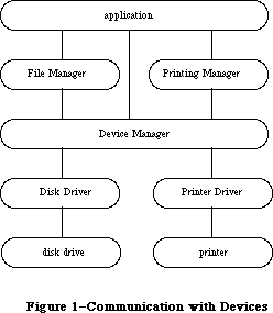 Figure 1–Communication with Devices
Warning: Information about desk accessories covered in the Desk Manager
chapter is not repeated here. Some information in this chapter
may not apply to desk accessories.
A device driver can be either open or closed. The Sound Driver and Disk Driver are opened when the system starts up; the rest of the drivers are opened at the specific request of an application. After a driver has been opened, an application can read data from and write data to it. You can close device drivers that are no longer in use, and recover the memory used by them. Up to 32 device drivers may be open at any one time.
Before it’s opened, you identify a device driver by its driver name; after it’s opened, you identify it by its reference number. A driver name consists of a period (.) followed by any sequence of 1 to 254 printing characters. A RAM driver’s name is the same as its resource name. You can use uppercase and lowercase letters when naming drivers, but the Device Manager ignores case when comparing names (it doesn’t ignore diacritical marks).
Note: Although device driver names can be quite long, there’s little
reason for them to be more than a few characters in length.
The Device Manager assigns each open device driver a driver reference number, from –1 to –32, that’s used instead of its driver name to refer to it.
Most communication between an application and an open device driver occurs by reading and writing data. Data read from a driver is placed in the
application’s data buffer, and data written to a driver is taken from the application’s data buffer. A data buffer is memory allocated by the application for communication with drivers.
In addition to data that’s read from or written to device drivers, drivers may require or provide other information. Information transmitted to a driver by an application is called control information; information provided by a driver is called status information. Control information may select modes of operation, start or stop processes, enable buffers, choose protocols, and so on. Status information may indicate the current mode of operation, the readiness of the device, the occurrence of errors, and so on. Each device driver may respond to a number of different types of control information and may provide a number of different types of status information.
Each of the standard Macintosh drivers includes predefined calls for transmitting control information and receiving status information. Explanations of these calls can be found in the chapters describing the drivers.
Note: The extensions to the Device Manager described in the following
paragraphs were originally documented in Inside Macintosh, Volume IV.
As such, this information refers to the 128K ROMs and System file
version 3.2 and later.
While no new routines have been added to the Device Manager with the Macintosh Plus, the handling of the existing routines has been significantly improved.
When an Open call is made, installed drivers are searched first (before resources) to avoid replacing a current driver; this search is done by name so be sure that your driver’s name is in the driver header. All drivers, exclusive of desk accessories, must have a name that begins with a period; otherwise, the Open call is passed on to the File Manager.
If a driver is already open, Open calls will not be sent to the driver’s open routine, preserving its device control entry. A desk accessory will, however, receive another call (certain desk accessories count on this).
If a driver fails to open because of a resource load problem, the Open call terminates with the appropriate error code instead of being passed on to the File Manager (which would usually return the result code fnfErr). If a driver returns a negative result code in register D0 from an Open call, the result code is passed back and the driver is not opened. If a driver returns the result code closeErr in register D0 from a Close call, this result code is passed back and the driver is not closed.
Open, Close, Read, Write, Control, and Status return all results in the ioResult field as well as in register D0. A KillIO call is passed to the driver only if it’s open and enabled for Control calls.
The number of device control entries in the 128K ROM has been increased from 32 to 48. The unit table is now a 192-byte nonrelocatable block containing 48
four-byte entries; the standard unit table assignments are as follows:
Unit Number Device
0 Reserved
1 Hard disk driver: Macintosh XL internal or Hard Disk 20 external
2 .Print driver
3 .Sound driver
4 .Sony driver
5 Modem port asynchronous driver input (.AIn)
6 Modem port asynchronous driver output (.AOut)
7 Printer port asynchronous driver input (.BIn)
8 Printer port asynchronous driver output (.BOut)
9 AppleTalk .MPP driver
10 AppleTalk .ATP driver
11 Reserved
12–26 Desk accessories in System file
27–31 Desk accessories in application files
32–39 SCSI drivers 0–7
40–47 Reserved
Note: The extensions to the Device Manager described in the following
paragraphs were originally documented in Inside Macintosh, Volume V.
As such, this information refers to the Macintosh SE and Macintosh II
ROMs and System file version 4.1 and later.
New modifications have been made to the Device Manager to support slot devices.
Reader’s guide: You need the information in the slot-related sections of
this chapter only if your application uses a specific card
(other than a standard video card) that plugs into a NuBus™
slot on the Macintosh II.
These slot-related sections cover the following subjects:
• the parts of the system startup procedure that affect slot devices
• how the Open call now handles slot devices
• how interrupts originating in slot devices are processed
• how the new Chooser works with slot devices
You’ll also need to be familiar with
• the Start Manager
• the Slot Manager
• the parts of the book “Designing Cards and Drivers for Macintosh
II and Macintosh SE” that pertain to the device your application uses.
_______________________________________________________________________________
»USING THE DEVICE MANAGER
_______________________________________________________________________________
You can call Device Manager routines via three different methods: high-level Pascal calls, low-level Pascal calls, and assembly language. The high-level Pascal calls are designed for Pascal programmers interested in using the Device Manager in a simple manner; they provide adequate device I/O and don’t require much special knowledge to use. The low-level Pascal and assembly-language calls are designed for advanced Pascal programmers and assembly-language programmers interested in using the Device Manager to its fullest capacity; they require some special knowledge to be used most effectively.
Note: The names used to refer to routines here are actually
assembly-language macro names for the low-level routines,
but the Pascal routine names are very similar.
The Device Manager is automatically initialized each time the system starts up.
Before an application can exchange information with a device driver, the driver must be opened. The Sound Driver and Disk Driver are opened when the system starts up; for other drivers, the application must call Open. The Open routine will return the driver reference number that you’ll use every time you want to refer to that device driver.
An application can send data from its data buffer to an open driver with a Write call, and transfer data from an open driver to its data buffer with Read. An application passes control information to a device driver by calling Control, and receives status information from a driver by calling Status.
Whenever you want to stop a device driver from completing I/O initiated by a Read, Write, Control, or Status call, call KillIO. KillIO halts any current I/O and deletes any pending I/O.
When you’re through using a driver, call Close. Close forces the device driver to complete any pending I/O, and then releases all the memory used by the driver.
_______________________________________________________________________________
»DEVICE MANAGER ROUTINES
_______________________________________________________________________________
This section describes the Device Manager routines used to call drivers. It’s divided into two parts: The first describes all the high-level Pascal routines of the Device Manager, and the second presents information about calling the low-level Pascal and assembly-language routines.
All the Device Manager routines in this section return an integer result code of type OSErr. Each routine description lists all of the applicable result codes, along with a short description of what the result code means. Lengthier explanations of all the result codes can be found in the summary at the end of this chapter.
_______________________________________________________________________________
»High-Level Device Manager Routines
Note: As described in the File Manager chapter, the FSRead and FSWrite
routines are also used to read from and write to files.
FUNCTION OpenDriver (name: Str255; VAR refNum: INTEGER) : OSErr; [Not in ROM]
OpenDriver opens the device driver specified by name and returns its reference number in refNum.
Result codes noErr No error
badUnitErr Bad reference number
dInstErr Couldn’t find driver in resource file
openErr Driver can’t perform the requested
reading or writing
unitEmptyErr Bad reference number
FUNCTION CloseDriver (refNum: INTEGER) : OSErr; [Not in ROM]
CloseDriver closes the device driver having the reference number refNum. Any pending I/O is completed, and the memory used by the driver is released.
Warning: Before using this command to close a particular driver, refer
to the chapter describing the driver for the consequences of
closing it.
Result codes noErr No error
badUnitErr Bad reference number
dRemoveErr Attempt to remove an open driver
unitEmptyErr Bad reference number
FUNCTION FSRead (refNum: INTEGER; VAR count: LONGINT;
buffPtr: Ptr) : OSErr; [Not in ROM]
FSRead attempts to read the number of bytes specified by the count parameter from the open device driver having the reference number refNum, and transfer them to the data buffer pointed to by buffPtr. After the read operation is completed, the number of bytes actually read is returned in the count parameter.
Result codes noErr No error
badUnitErr Bad reference number
notOpenErr Driver isn’t open
unitEmptyErr Bad reference number
readErr Driver can’t respond to Read calls
FUNCTION FSWrite (refNum: INTEGER; VAR count: LONGINT;
buffPtr: Ptr) : OSErr; [Not in ROM]
FSWrite takes the number of bytes specified by the count parameter from the buffer pointed to by buffPtr and attempts to write them to the open device driver having the reference number refNum. After the write operation is completed, the number of bytes actually written is returned in the count parameter.
Result codes noErr No error
badUnitErr Bad reference number
notOpenErr Driver isn’t open
unitEmptyErr Bad reference number
writErr Driver can’t respond to Write calls
FUNCTION Control (refNum: INTEGER; csCode: INTEGER;
csParamPtr: Ptr) : OSErr; [Not in ROM]
Control sends control information to the device driver having the reference number refNum. The type of information sent is specified by csCode, and the information itself is pointed to by csParamPtr. The values passed in csCode and pointed to by csParamPtr depend on the driver being called.
Result codes noErr No error
badUnitErr Bad reference number
notOpenErr Driver isn’t open
unitEmptyErr Bad reference number
controlErr Driver can’t respond to this Control call
FUNCTION Status (refNum: INTEGER; csCode: INTEGER;
csParamPtr: Ptr) : OSErr; [Not in ROM]
Status returns status information about the device driver having the reference number refNum. The type of information returned is specified by csCode, and the information itself is pointed to by csParamPtr. The values passed in csCode and pointed to by csParamPtr depend on the driver being called.
Result codes noErr No error
badUnitErr Bad reference number
notOpenErr Driver isn’t open
unitEmptyErr Bad reference number
statusErr Driver can’t respond to this Status call
FUNCTION KillIO (refNum: INTEGER) : OSErr; [Not in ROM]
KillIO terminates all current and pending I/O with the device driver having the reference number refNum.
Result codes noErr No error
badUnitErr Bad reference number
unitEmptyErr Bad reference number
_______________________________________________________________________________
»Low-Level Device Manager Routines
This section contains special information for programmers using the low-level Pascal or assembly-language routines of the Device Manager, and describes them in detail.
Note: The Device Manager routines for writing device drivers are
described in the section “Writing Your Own Device Drivers”.
All low-level Device Manager routines can be executed either synchronously
(meaning that the application can’t continue until the routine is completed) or asynchronously (meaning that the application is free to perform other tasks while the routine is executing). Some cannot be executed asynchronously, because they use the Memory Manager to allocate and release memory.
When an application calls a Device Manager routine asynchronously, an I/O request is placed in the driver I/O queue, and control returns to the calling program—possibly even before the actual I/O is completed. Requests are taken from the queue one at a time, and processed; meanwhile, the calling program is free to work on other things.
The calling program may specify a completion routine to be executed at the end of an asynchronous operation.
Routine parameters passed by an application to the Device Manager and returned by the Device Manager to an application are contained in a parameter block, which is a data structure in the heap or stack. All low-level Pascal calls to the Device Manager are of the form
FUNCTION PBCallName (paramBlock: ParmBlkPtr; async: BOOLEAN) : OSErr;
PBCallName is the name of the routine. ParamBlock points to the parameter block containing the parameters for the routine. If async is TRUE, the call is executed asynchronously; otherwise the call is executed synchronously. Each call returns an integer result code of type OSErr.
Assembly-language note: When you call a Device Manager routine, A0 must
point to a parameter block containing the
parameters for the routine. If you want the
routine to be executed asynchronously, set bit 10
of the routine trap word. You can do this by
supplying the word ASYNC as the second argument
to the routine macro. For example:
_Read ,ASYNC
You can set or test bit 10 of a trap word by using
the global constant asyncTrpBit.
If you want a routine to be executed immediately
(bypassing the driver I/O queue), set bit 9 of the
routine trap word. This can be accomplished by
supplying the word IMMED as the second argument
to the routine macro. (The driver must be able to
handle immediate calls for this to work.) For example:
_Write ,IMMED
You can set or test bit 9 of a trap word by using
the global constant noQueueBit. You can specify
either ASYNC or IMMED, but not both. (The syntax
shown above applies to the Macintosh Programmers
Workshop Assembler; programmers using another
development system should consult its documentation
for the proper syntax.)
All routines return a result code in D0.
»Routine Parameters
There are two different kinds of parameter blocks you’ll pass to Device Manager routines: one for I/O routines and another for Control and Status calls.
The lengthy, variable-length data structure of a parameter block is given below. The Device Manager and File Manager use this same data structure, but only the parts relevant to the Device Manager are discussed here. Each kind of parameter block contains eight fields of standard information and three to nine fields of additional information:
TYPE ParamBlkType = (ioParam,fileParam,volumeParam,cntrlParam);
ParamBlockRec = RECORD
qLink: QElemPtr; {next queue entry}
qType: INTEGER; {queue type}
ioTrap: INTEGER; {routine trap}
ioCmdAddr: Ptr; {routine address}
ioCompletion: ProcPtr; {completion routine}
ioResult: OSErr; {result code}
ioNamePtr: StringPtr; {driver name}
ioVRefNum: INTEGER; {volume reference or }
{ drive number}
CASE ParamBlkType OF
ioParam:
. . . {I/O routine parameters}
fileParam:
. . . {used by the File Manager}
volumeParam:
. . . {used by the File Manager}
cntrlParam:
. . . {Control and Status call parameters}
END;
ParmBlkPtr = ^ParamBlockRec;
The first four fields in each parameter block are handled entirely by the Device Manager, and most programmers needn’t be concerned with them; programmers who are interested in them should see the section “The Structure of a Device Driver”.
IOCompletion contains a pointer to a completion routine to be executed at the end of an asynchronous call; it should be NIL for asynchronous calls with no completion routine, and is automatically set to NIL for all synchronous calls.
Warning: Completion routines are executed at the interrupt level and must
preserve all registers other than A0, A1, and D0-D2. Your completion
routine must not make any calls to the Memory Manager, directly or
indirectly, and can’t depend on handles to unlocked blocks being
valid. If it uses application globals, it must also ensure that
register A5 contains the address of the boundary between the
application globals and the application parameters; for details,
see SetCurrentA5 and SetA5 in Macintosh Technical Note #208.
X-Ref: Technical Note #208
Assembly-language note: When your completion routine is called, register A0
points to the parameter block of the asynchronous
call and register D0 contains the result code.
Routines that are executed asynchronously return control to the calling program with the result code noErr as soon as the call is placed in the driver I/O queue. This isn’t an indication of successful call completion, but simply indicates that the call was successfully queued. To determine when the call is actually completed, you can poll the ioResult field; this field is set to 1 when the call is made, and receives the actual result code upon completion of the call. Completion routines are executed after the result code is placed in ioResult.
IONamePtr is a pointer to the name of a driver and is used only for calls to the Open function. IOVRefNum is used by the Disk Driver to identify drives.
I/O routines use the following additional fields:
ioParam:
(ioRefNum: INTEGER; {driver reference number}
ioVersNum: SignedByte; {not used}
ioPermssn: SignedByte; {read/write permission}
ioMisc: Ptr; {not used}
ioBuffer: Ptr; {pointer to data buffer}
ioReqCount: LONGINT; {requested number of bytes}
ioActCount: LONGINT; {actual number of bytes}
ioPosMode: INTEGER; {positioning mode}
ioPosOffset: LONGINT); {positioning offset}
IOPermssn requests permission to read from or write to a driver when the driver is opened, and must contain one of the following values:
CONST fsCurPerm = 0; {whatever is currently allowed}
fsRdPerm = 1; {request to read only}
fsWrPerm = 2; {request to write only}
fsRdWrPerm = 3; {request to read and write}
This request is compared with the capabilities of the driver (some drivers are read-only, some are write-only). If the driver is incapable of performing as requested, a result code indicating the error is returned.
IOBuffer points to a data buffer into which data is written by Read calls and from which data is read by Write calls. IOReqCount specifies the requested number of bytes to be read or written. IOActCount contains the number of bytes actually read or written.
IOPosMode and ioPosOffset contain positioning information used for Read and Write calls by drivers of block devices. IOPosMode contains the positioning mode; bits 0 and 1 indicate where an operation should begin relative to the physical beginning of the block-formatted medium (such as a disk). You can use the following predefined constants to test or set the value of these bits:
CONST fsAtMark = 0; {at current position}
fsFromStar = 1; {offset relative to beginning of medium}
fsFromMark = 3; {offset relative to current position}
IOPosOffset specifies the byte offset (either positive or negative), relative to the position specified by the positioning mode, where the operation will be performed (except when the positioning mode is fsAtMark, in which case ioPosOffset is ignored). IOPosOffset must be a 512-byte multiple.
To verify that data written to a block device matches the data in memory, make a Read call right after the Write call. The parameters for a read-verify operation are the same as for a standard Read call, except that the following constant must be added to the positioning mode:
CONST rdVerify = 64; {read-verify mode}
The result code ioErr is returned if any of the data doesn’t match.
Control and Status calls use three additional fields:
cntrlParam:
(ioCRefNum: INTEGER; {driver reference number}
csCode: INTEGER; {type of Control or Status call}
csParam: ARRAY[0..10] OF INTEGER); {control or status information}
IOCRefNum contains the reference number of the device driver. The csCode field contains a number identifying the type of call; this number may be interpreted differently by each driver. The csParam field contains the control or status information for the call; it’s declared as up to 22 bytes of information because its exact contents will vary from one Control or Status call to the next. To store information in this field, you must perform the proper type coercion.
»Routine Descriptions
This section describes the procedures and functions. Each routine description includes the low-level Pascal form of the call and the routine’s assembly-language macro. A list of the fields in the parameter block affected by the call is also given.
Assembly-language note: The field names given in these descriptions are
those of the ParamBlockRec data type; see the
summary at the end of this chapter for the names
of the corresponding assembly-language offsets.
(The names for some offsets differ from their
Pascal equivalents, and in certain cases more than
one name for the same offset is provided.)
The number next to each parameter name indicates the byte offset of the parameter from the start of the parameter block pointed to by register A0; only assembly-language programmers need be concerned with it. An arrow next to each parameter name indicates whether it’s an input, output, or input/output parameter:
Arrow Meaning
--> Parameter is passed to the routine
<-- Parameter is returned by the routine
<-> Parameter is passed to and returned by the routine
Note: As described in the File Manager chapter, the Open and Close
functions are also used to open and close files.
FUNCTION PBOpen (paramBlock: ParmBlkPtr; async: BOOLEAN) : OSErr;
Parameter block
--> 12 ioCompletion pointer
<-- 16 ioResult word
--> 18 ioNamePtr pointer
<-- 24 ioRefNum word
--> 27 ioPermssn byte
PBOpen opens the device driver specified by ioNamePtr, reading it into memory if necessary, and returns its reference number in ioRefNum. IOPermssn specifies the requested read/write permission.
Result codes noErr No error
badUnitErr Bad reference number
dInstErr Couldn’t find driver in resource file
openErr Driver can’t perform the requested
reading or writing
unitEmptyErr Bad reference number
FUNCTION PBClose (paramBlock: ParmBlkPtr; async: BOOLEAN) : OSErr;
Trap macro _Close
Parameter block
--> 12 ioCompletion pointer
<-- 16 ioResult word
--> 24 ioRefNum word
PBClose closes the device driver having the reference number ioRefNum. Any pending I/O is completed, and the memory used by the driver is released.
Result codes noErr No error
badUnitErr Bad reference number
dRemovErr Attempt to remove an open driver
unitEmptyErr Bad reference number
FUNCTION PBRead (paramBlock: ParmBlkPtr; async: BOOLEAN) : OSErr;
Trap macro _Read
X-Ref: Technical Note #187
Parameter block
--> 12 ioCompletion pointer
<-- 16 ioResult word
--> 22 ioVRefNum word
--> 24 ioRefNum word
--> 32 ioBuffer pointer
--> 36 ioReqCount long word
<-- 40 ioActCount long word
--> 44 ioPosMode word
<-> 46 ioPosOffset long word
PBRead attempts to read ioReqCount bytes from the device driver having the reference number ioRefNum, and transfer them to the data buffer pointed to by ioBuffer. The drive number, if any, of the device to be read from is specified by ioVRefNum. After the read is completed, the position is returned in ioPosOffset and the number of bytes actually read is returned in ioActCount.
Result codes noErr No error
badUnitErr Bad reference number
notOpenErr Driver isn’t open
unitEmptyErr Bad reference number
readErr Driver can’t respond to Read calls
FUNCTION PBWrite (paramBlock: ParmBlkPtr; async: BOOLEAN) : OSErr;
Trap macro _Write
X-Ref: Technical Note #187
Parameter block
--> 12 ioCompletion pointer
<-- 16 ioResult word
--> 22 ioVRefNum word
--> 24 ioRefNum word
--> 32 ioBuffer pointer
--> 36 ioReqCount long word
<-- 40 ioActCount long word
--> 44 ioPosMode word
<-> 46 ioPosOffset long word
PBWrite takes ioReqCount bytes from the buffer pointed to by ioBuffer and attempts to write them to the device driver having the reference number ioRefNum. The drive number, if any, of the device to be written to is specified by ioVRefNum. After the write is completed, the position is returned in ioPosOffset and the number of bytes actually written is returned in ioActCount.
Result codes noErr No error
badUnitErr Bad reference number
notOpenErr Driver isn’t open
unitEmptyErr Bad reference number
writErr Driver can’t respond to Write calls
FUNCTION PBControl (paramBlock: ParmBlkPtr; async: BOOLEAN) : OSErr;
Trap macro _Control
Parameter block
--> 12 ioCompletion pointer
<-- 16 ioResult word
--> 22 ioVRefNum word
--> 24 ioRefNum word
--> 26 csCode word
--> 28 csParam record
PBControl sends control information to the device driver having the reference number ioRefNum; the drive number, if any, is specified by ioVRefNum. The type of information sent is specified by csCode, and the information itself begins at csParam. The values passed in csCode and csParam depend on the driver being called.
Result codes noErr No error
badUnitErr Bad reference number
notOpenErr Driver isn’t open
unitEmptyErr Bad reference number
controlErr Driver can’t respond to this Control call
FUNCTION PBStatus (paramBlock: ParmBlkPtr; async: BOOLEAN) : OSErr;
Trap macro _Status
Parameter block
--> 12 ioCompletion pointer
<-- 16 ioResult word
--> 22 ioVRefNum word
--> 24 ioRefNum word
--> 26 csCode word
<-- 28 csParam record
PBStatus returns status information about the device driver having the reference number ioRefNum; the drive number, if any, is specified by ioVRefNum. The type of information returned is specified by csCode, and the information itself begins at csParam. The values passed in csCode and csParam depend on the driver being called.
Result codes noErr No error
badUnitErr Bad reference number
notOpenErr Driver isn’t open
unitEmptyErr Bad reference number
statusErr Driver can’t respond to this Status call
FUNCTION PBKillIO (paramBlock: ParmBlkPtr; async: BOOLEAN) : OSErr;
Trap macro _KillIO
Parameter block
--> 12 ioCompletion pointer
<-- 16 ioResult word
--> 24 ioRefNum word
PBKillIO stops any current I/O request being processed, and removes all pending I/O requests from the I/O queue of the device driver having the reference number ioRefNum. The completion routine of each pending I/O request is called, with the ioResult field of each request equal to the result code abortErr.
Result codes noErr No error
badUnitErr Bad reference number
unitEmptyErr Bad reference number
_______________________________________________________________________________
»THE STRUCTURE OF A DEVICE DRIVER
_______________________________________________________________________________
This section describes the structure of device drivers for programmers interested in writing their own driver or manipulating existing drivers. Some of the information presented here is accessible only through assembly language.
RAM drivers are stored in resource files. The resource type for drivers is
'DRVR'. The resource name is the driver name. The resource ID for a driver is its unit number (explained below) and must be between 0 and 31 inclusive.
Warning: Don’t use the unit number of an existing driver unless you
want the existing driver to be replaced.
As shown in Figure 2, a driver begins with a few words of flags and other data, followed by offsets to the routines that do the work of the driver, an optional title, and finally the routines themselves.
Every driver contains a routine to handle Open and Close calls, and may contain routines to handle Read, Write, Control, Status, and KillIO calls. The driver routines that handle Device Manager calls are as follows:
Device Manager call Driver routine
Open Open
Read Prime
Write Prime
Control Control
KillIO Control
Status Status
Close Close
Figure 1–Communication with Devices
Warning: Information about desk accessories covered in the Desk Manager
chapter is not repeated here. Some information in this chapter
may not apply to desk accessories.
A device driver can be either open or closed. The Sound Driver and Disk Driver are opened when the system starts up; the rest of the drivers are opened at the specific request of an application. After a driver has been opened, an application can read data from and write data to it. You can close device drivers that are no longer in use, and recover the memory used by them. Up to 32 device drivers may be open at any one time.
Before it’s opened, you identify a device driver by its driver name; after it’s opened, you identify it by its reference number. A driver name consists of a period (.) followed by any sequence of 1 to 254 printing characters. A RAM driver’s name is the same as its resource name. You can use uppercase and lowercase letters when naming drivers, but the Device Manager ignores case when comparing names (it doesn’t ignore diacritical marks).
Note: Although device driver names can be quite long, there’s little
reason for them to be more than a few characters in length.
The Device Manager assigns each open device driver a driver reference number, from –1 to –32, that’s used instead of its driver name to refer to it.
Most communication between an application and an open device driver occurs by reading and writing data. Data read from a driver is placed in the
application’s data buffer, and data written to a driver is taken from the application’s data buffer. A data buffer is memory allocated by the application for communication with drivers.
In addition to data that’s read from or written to device drivers, drivers may require or provide other information. Information transmitted to a driver by an application is called control information; information provided by a driver is called status information. Control information may select modes of operation, start or stop processes, enable buffers, choose protocols, and so on. Status information may indicate the current mode of operation, the readiness of the device, the occurrence of errors, and so on. Each device driver may respond to a number of different types of control information and may provide a number of different types of status information.
Each of the standard Macintosh drivers includes predefined calls for transmitting control information and receiving status information. Explanations of these calls can be found in the chapters describing the drivers.
Note: The extensions to the Device Manager described in the following
paragraphs were originally documented in Inside Macintosh, Volume IV.
As such, this information refers to the 128K ROMs and System file
version 3.2 and later.
While no new routines have been added to the Device Manager with the Macintosh Plus, the handling of the existing routines has been significantly improved.
When an Open call is made, installed drivers are searched first (before resources) to avoid replacing a current driver; this search is done by name so be sure that your driver’s name is in the driver header. All drivers, exclusive of desk accessories, must have a name that begins with a period; otherwise, the Open call is passed on to the File Manager.
If a driver is already open, Open calls will not be sent to the driver’s open routine, preserving its device control entry. A desk accessory will, however, receive another call (certain desk accessories count on this).
If a driver fails to open because of a resource load problem, the Open call terminates with the appropriate error code instead of being passed on to the File Manager (which would usually return the result code fnfErr). If a driver returns a negative result code in register D0 from an Open call, the result code is passed back and the driver is not opened. If a driver returns the result code closeErr in register D0 from a Close call, this result code is passed back and the driver is not closed.
Open, Close, Read, Write, Control, and Status return all results in the ioResult field as well as in register D0. A KillIO call is passed to the driver only if it’s open and enabled for Control calls.
The number of device control entries in the 128K ROM has been increased from 32 to 48. The unit table is now a 192-byte nonrelocatable block containing 48
four-byte entries; the standard unit table assignments are as follows:
Unit Number Device
0 Reserved
1 Hard disk driver: Macintosh XL internal or Hard Disk 20 external
2 .Print driver
3 .Sound driver
4 .Sony driver
5 Modem port asynchronous driver input (.AIn)
6 Modem port asynchronous driver output (.AOut)
7 Printer port asynchronous driver input (.BIn)
8 Printer port asynchronous driver output (.BOut)
9 AppleTalk .MPP driver
10 AppleTalk .ATP driver
11 Reserved
12–26 Desk accessories in System file
27–31 Desk accessories in application files
32–39 SCSI drivers 0–7
40–47 Reserved
Note: The extensions to the Device Manager described in the following
paragraphs were originally documented in Inside Macintosh, Volume V.
As such, this information refers to the Macintosh SE and Macintosh II
ROMs and System file version 4.1 and later.
New modifications have been made to the Device Manager to support slot devices.
Reader’s guide: You need the information in the slot-related sections of
this chapter only if your application uses a specific card
(other than a standard video card) that plugs into a NuBus™
slot on the Macintosh II.
These slot-related sections cover the following subjects:
• the parts of the system startup procedure that affect slot devices
• how the Open call now handles slot devices
• how interrupts originating in slot devices are processed
• how the new Chooser works with slot devices
You’ll also need to be familiar with
• the Start Manager
• the Slot Manager
• the parts of the book “Designing Cards and Drivers for Macintosh
II and Macintosh SE” that pertain to the device your application uses.
_______________________________________________________________________________
»USING THE DEVICE MANAGER
_______________________________________________________________________________
You can call Device Manager routines via three different methods: high-level Pascal calls, low-level Pascal calls, and assembly language. The high-level Pascal calls are designed for Pascal programmers interested in using the Device Manager in a simple manner; they provide adequate device I/O and don’t require much special knowledge to use. The low-level Pascal and assembly-language calls are designed for advanced Pascal programmers and assembly-language programmers interested in using the Device Manager to its fullest capacity; they require some special knowledge to be used most effectively.
Note: The names used to refer to routines here are actually
assembly-language macro names for the low-level routines,
but the Pascal routine names are very similar.
The Device Manager is automatically initialized each time the system starts up.
Before an application can exchange information with a device driver, the driver must be opened. The Sound Driver and Disk Driver are opened when the system starts up; for other drivers, the application must call Open. The Open routine will return the driver reference number that you’ll use every time you want to refer to that device driver.
An application can send data from its data buffer to an open driver with a Write call, and transfer data from an open driver to its data buffer with Read. An application passes control information to a device driver by calling Control, and receives status information from a driver by calling Status.
Whenever you want to stop a device driver from completing I/O initiated by a Read, Write, Control, or Status call, call KillIO. KillIO halts any current I/O and deletes any pending I/O.
When you’re through using a driver, call Close. Close forces the device driver to complete any pending I/O, and then releases all the memory used by the driver.
_______________________________________________________________________________
»DEVICE MANAGER ROUTINES
_______________________________________________________________________________
This section describes the Device Manager routines used to call drivers. It’s divided into two parts: The first describes all the high-level Pascal routines of the Device Manager, and the second presents information about calling the low-level Pascal and assembly-language routines.
All the Device Manager routines in this section return an integer result code of type OSErr. Each routine description lists all of the applicable result codes, along with a short description of what the result code means. Lengthier explanations of all the result codes can be found in the summary at the end of this chapter.
_______________________________________________________________________________
»High-Level Device Manager Routines
Note: As described in the File Manager chapter, the FSRead and FSWrite
routines are also used to read from and write to files.
FUNCTION OpenDriver (name: Str255; VAR refNum: INTEGER) : OSErr; [Not in ROM]
OpenDriver opens the device driver specified by name and returns its reference number in refNum.
Result codes noErr No error
badUnitErr Bad reference number
dInstErr Couldn’t find driver in resource file
openErr Driver can’t perform the requested
reading or writing
unitEmptyErr Bad reference number
FUNCTION CloseDriver (refNum: INTEGER) : OSErr; [Not in ROM]
CloseDriver closes the device driver having the reference number refNum. Any pending I/O is completed, and the memory used by the driver is released.
Warning: Before using this command to close a particular driver, refer
to the chapter describing the driver for the consequences of
closing it.
Result codes noErr No error
badUnitErr Bad reference number
dRemoveErr Attempt to remove an open driver
unitEmptyErr Bad reference number
FUNCTION FSRead (refNum: INTEGER; VAR count: LONGINT;
buffPtr: Ptr) : OSErr; [Not in ROM]
FSRead attempts to read the number of bytes specified by the count parameter from the open device driver having the reference number refNum, and transfer them to the data buffer pointed to by buffPtr. After the read operation is completed, the number of bytes actually read is returned in the count parameter.
Result codes noErr No error
badUnitErr Bad reference number
notOpenErr Driver isn’t open
unitEmptyErr Bad reference number
readErr Driver can’t respond to Read calls
FUNCTION FSWrite (refNum: INTEGER; VAR count: LONGINT;
buffPtr: Ptr) : OSErr; [Not in ROM]
FSWrite takes the number of bytes specified by the count parameter from the buffer pointed to by buffPtr and attempts to write them to the open device driver having the reference number refNum. After the write operation is completed, the number of bytes actually written is returned in the count parameter.
Result codes noErr No error
badUnitErr Bad reference number
notOpenErr Driver isn’t open
unitEmptyErr Bad reference number
writErr Driver can’t respond to Write calls
FUNCTION Control (refNum: INTEGER; csCode: INTEGER;
csParamPtr: Ptr) : OSErr; [Not in ROM]
Control sends control information to the device driver having the reference number refNum. The type of information sent is specified by csCode, and the information itself is pointed to by csParamPtr. The values passed in csCode and pointed to by csParamPtr depend on the driver being called.
Result codes noErr No error
badUnitErr Bad reference number
notOpenErr Driver isn’t open
unitEmptyErr Bad reference number
controlErr Driver can’t respond to this Control call
FUNCTION Status (refNum: INTEGER; csCode: INTEGER;
csParamPtr: Ptr) : OSErr; [Not in ROM]
Status returns status information about the device driver having the reference number refNum. The type of information returned is specified by csCode, and the information itself is pointed to by csParamPtr. The values passed in csCode and pointed to by csParamPtr depend on the driver being called.
Result codes noErr No error
badUnitErr Bad reference number
notOpenErr Driver isn’t open
unitEmptyErr Bad reference number
statusErr Driver can’t respond to this Status call
FUNCTION KillIO (refNum: INTEGER) : OSErr; [Not in ROM]
KillIO terminates all current and pending I/O with the device driver having the reference number refNum.
Result codes noErr No error
badUnitErr Bad reference number
unitEmptyErr Bad reference number
_______________________________________________________________________________
»Low-Level Device Manager Routines
This section contains special information for programmers using the low-level Pascal or assembly-language routines of the Device Manager, and describes them in detail.
Note: The Device Manager routines for writing device drivers are
described in the section “Writing Your Own Device Drivers”.
All low-level Device Manager routines can be executed either synchronously
(meaning that the application can’t continue until the routine is completed) or asynchronously (meaning that the application is free to perform other tasks while the routine is executing). Some cannot be executed asynchronously, because they use the Memory Manager to allocate and release memory.
When an application calls a Device Manager routine asynchronously, an I/O request is placed in the driver I/O queue, and control returns to the calling program—possibly even before the actual I/O is completed. Requests are taken from the queue one at a time, and processed; meanwhile, the calling program is free to work on other things.
The calling program may specify a completion routine to be executed at the end of an asynchronous operation.
Routine parameters passed by an application to the Device Manager and returned by the Device Manager to an application are contained in a parameter block, which is a data structure in the heap or stack. All low-level Pascal calls to the Device Manager are of the form
FUNCTION PBCallName (paramBlock: ParmBlkPtr; async: BOOLEAN) : OSErr;
PBCallName is the name of the routine. ParamBlock points to the parameter block containing the parameters for the routine. If async is TRUE, the call is executed asynchronously; otherwise the call is executed synchronously. Each call returns an integer result code of type OSErr.
Assembly-language note: When you call a Device Manager routine, A0 must
point to a parameter block containing the
parameters for the routine. If you want the
routine to be executed asynchronously, set bit 10
of the routine trap word. You can do this by
supplying the word ASYNC as the second argument
to the routine macro. For example:
_Read ,ASYNC
You can set or test bit 10 of a trap word by using
the global constant asyncTrpBit.
If you want a routine to be executed immediately
(bypassing the driver I/O queue), set bit 9 of the
routine trap word. This can be accomplished by
supplying the word IMMED as the second argument
to the routine macro. (The driver must be able to
handle immediate calls for this to work.) For example:
_Write ,IMMED
You can set or test bit 9 of a trap word by using
the global constant noQueueBit. You can specify
either ASYNC or IMMED, but not both. (The syntax
shown above applies to the Macintosh Programmers
Workshop Assembler; programmers using another
development system should consult its documentation
for the proper syntax.)
All routines return a result code in D0.
»Routine Parameters
There are two different kinds of parameter blocks you’ll pass to Device Manager routines: one for I/O routines and another for Control and Status calls.
The lengthy, variable-length data structure of a parameter block is given below. The Device Manager and File Manager use this same data structure, but only the parts relevant to the Device Manager are discussed here. Each kind of parameter block contains eight fields of standard information and three to nine fields of additional information:
TYPE ParamBlkType = (ioParam,fileParam,volumeParam,cntrlParam);
ParamBlockRec = RECORD
qLink: QElemPtr; {next queue entry}
qType: INTEGER; {queue type}
ioTrap: INTEGER; {routine trap}
ioCmdAddr: Ptr; {routine address}
ioCompletion: ProcPtr; {completion routine}
ioResult: OSErr; {result code}
ioNamePtr: StringPtr; {driver name}
ioVRefNum: INTEGER; {volume reference or }
{ drive number}
CASE ParamBlkType OF
ioParam:
. . . {I/O routine parameters}
fileParam:
. . . {used by the File Manager}
volumeParam:
. . . {used by the File Manager}
cntrlParam:
. . . {Control and Status call parameters}
END;
ParmBlkPtr = ^ParamBlockRec;
The first four fields in each parameter block are handled entirely by the Device Manager, and most programmers needn’t be concerned with them; programmers who are interested in them should see the section “The Structure of a Device Driver”.
IOCompletion contains a pointer to a completion routine to be executed at the end of an asynchronous call; it should be NIL for asynchronous calls with no completion routine, and is automatically set to NIL for all synchronous calls.
Warning: Completion routines are executed at the interrupt level and must
preserve all registers other than A0, A1, and D0-D2. Your completion
routine must not make any calls to the Memory Manager, directly or
indirectly, and can’t depend on handles to unlocked blocks being
valid. If it uses application globals, it must also ensure that
register A5 contains the address of the boundary between the
application globals and the application parameters; for details,
see SetCurrentA5 and SetA5 in Macintosh Technical Note #208.
X-Ref: Technical Note #208
Assembly-language note: When your completion routine is called, register A0
points to the parameter block of the asynchronous
call and register D0 contains the result code.
Routines that are executed asynchronously return control to the calling program with the result code noErr as soon as the call is placed in the driver I/O queue. This isn’t an indication of successful call completion, but simply indicates that the call was successfully queued. To determine when the call is actually completed, you can poll the ioResult field; this field is set to 1 when the call is made, and receives the actual result code upon completion of the call. Completion routines are executed after the result code is placed in ioResult.
IONamePtr is a pointer to the name of a driver and is used only for calls to the Open function. IOVRefNum is used by the Disk Driver to identify drives.
I/O routines use the following additional fields:
ioParam:
(ioRefNum: INTEGER; {driver reference number}
ioVersNum: SignedByte; {not used}
ioPermssn: SignedByte; {read/write permission}
ioMisc: Ptr; {not used}
ioBuffer: Ptr; {pointer to data buffer}
ioReqCount: LONGINT; {requested number of bytes}
ioActCount: LONGINT; {actual number of bytes}
ioPosMode: INTEGER; {positioning mode}
ioPosOffset: LONGINT); {positioning offset}
IOPermssn requests permission to read from or write to a driver when the driver is opened, and must contain one of the following values:
CONST fsCurPerm = 0; {whatever is currently allowed}
fsRdPerm = 1; {request to read only}
fsWrPerm = 2; {request to write only}
fsRdWrPerm = 3; {request to read and write}
This request is compared with the capabilities of the driver (some drivers are read-only, some are write-only). If the driver is incapable of performing as requested, a result code indicating the error is returned.
IOBuffer points to a data buffer into which data is written by Read calls and from which data is read by Write calls. IOReqCount specifies the requested number of bytes to be read or written. IOActCount contains the number of bytes actually read or written.
IOPosMode and ioPosOffset contain positioning information used for Read and Write calls by drivers of block devices. IOPosMode contains the positioning mode; bits 0 and 1 indicate where an operation should begin relative to the physical beginning of the block-formatted medium (such as a disk). You can use the following predefined constants to test or set the value of these bits:
CONST fsAtMark = 0; {at current position}
fsFromStar = 1; {offset relative to beginning of medium}
fsFromMark = 3; {offset relative to current position}
IOPosOffset specifies the byte offset (either positive or negative), relative to the position specified by the positioning mode, where the operation will be performed (except when the positioning mode is fsAtMark, in which case ioPosOffset is ignored). IOPosOffset must be a 512-byte multiple.
To verify that data written to a block device matches the data in memory, make a Read call right after the Write call. The parameters for a read-verify operation are the same as for a standard Read call, except that the following constant must be added to the positioning mode:
CONST rdVerify = 64; {read-verify mode}
The result code ioErr is returned if any of the data doesn’t match.
Control and Status calls use three additional fields:
cntrlParam:
(ioCRefNum: INTEGER; {driver reference number}
csCode: INTEGER; {type of Control or Status call}
csParam: ARRAY[0..10] OF INTEGER); {control or status information}
IOCRefNum contains the reference number of the device driver. The csCode field contains a number identifying the type of call; this number may be interpreted differently by each driver. The csParam field contains the control or status information for the call; it’s declared as up to 22 bytes of information because its exact contents will vary from one Control or Status call to the next. To store information in this field, you must perform the proper type coercion.
»Routine Descriptions
This section describes the procedures and functions. Each routine description includes the low-level Pascal form of the call and the routine’s assembly-language macro. A list of the fields in the parameter block affected by the call is also given.
Assembly-language note: The field names given in these descriptions are
those of the ParamBlockRec data type; see the
summary at the end of this chapter for the names
of the corresponding assembly-language offsets.
(The names for some offsets differ from their
Pascal equivalents, and in certain cases more than
one name for the same offset is provided.)
The number next to each parameter name indicates the byte offset of the parameter from the start of the parameter block pointed to by register A0; only assembly-language programmers need be concerned with it. An arrow next to each parameter name indicates whether it’s an input, output, or input/output parameter:
Arrow Meaning
--> Parameter is passed to the routine
<-- Parameter is returned by the routine
<-> Parameter is passed to and returned by the routine
Note: As described in the File Manager chapter, the Open and Close
functions are also used to open and close files.
FUNCTION PBOpen (paramBlock: ParmBlkPtr; async: BOOLEAN) : OSErr;
Parameter block
--> 12 ioCompletion pointer
<-- 16 ioResult word
--> 18 ioNamePtr pointer
<-- 24 ioRefNum word
--> 27 ioPermssn byte
PBOpen opens the device driver specified by ioNamePtr, reading it into memory if necessary, and returns its reference number in ioRefNum. IOPermssn specifies the requested read/write permission.
Result codes noErr No error
badUnitErr Bad reference number
dInstErr Couldn’t find driver in resource file
openErr Driver can’t perform the requested
reading or writing
unitEmptyErr Bad reference number
FUNCTION PBClose (paramBlock: ParmBlkPtr; async: BOOLEAN) : OSErr;
Trap macro _Close
Parameter block
--> 12 ioCompletion pointer
<-- 16 ioResult word
--> 24 ioRefNum word
PBClose closes the device driver having the reference number ioRefNum. Any pending I/O is completed, and the memory used by the driver is released.
Result codes noErr No error
badUnitErr Bad reference number
dRemovErr Attempt to remove an open driver
unitEmptyErr Bad reference number
FUNCTION PBRead (paramBlock: ParmBlkPtr; async: BOOLEAN) : OSErr;
Trap macro _Read
X-Ref: Technical Note #187
Parameter block
--> 12 ioCompletion pointer
<-- 16 ioResult word
--> 22 ioVRefNum word
--> 24 ioRefNum word
--> 32 ioBuffer pointer
--> 36 ioReqCount long word
<-- 40 ioActCount long word
--> 44 ioPosMode word
<-> 46 ioPosOffset long word
PBRead attempts to read ioReqCount bytes from the device driver having the reference number ioRefNum, and transfer them to the data buffer pointed to by ioBuffer. The drive number, if any, of the device to be read from is specified by ioVRefNum. After the read is completed, the position is returned in ioPosOffset and the number of bytes actually read is returned in ioActCount.
Result codes noErr No error
badUnitErr Bad reference number
notOpenErr Driver isn’t open
unitEmptyErr Bad reference number
readErr Driver can’t respond to Read calls
FUNCTION PBWrite (paramBlock: ParmBlkPtr; async: BOOLEAN) : OSErr;
Trap macro _Write
X-Ref: Technical Note #187
Parameter block
--> 12 ioCompletion pointer
<-- 16 ioResult word
--> 22 ioVRefNum word
--> 24 ioRefNum word
--> 32 ioBuffer pointer
--> 36 ioReqCount long word
<-- 40 ioActCount long word
--> 44 ioPosMode word
<-> 46 ioPosOffset long word
PBWrite takes ioReqCount bytes from the buffer pointed to by ioBuffer and attempts to write them to the device driver having the reference number ioRefNum. The drive number, if any, of the device to be written to is specified by ioVRefNum. After the write is completed, the position is returned in ioPosOffset and the number of bytes actually written is returned in ioActCount.
Result codes noErr No error
badUnitErr Bad reference number
notOpenErr Driver isn’t open
unitEmptyErr Bad reference number
writErr Driver can’t respond to Write calls
FUNCTION PBControl (paramBlock: ParmBlkPtr; async: BOOLEAN) : OSErr;
Trap macro _Control
Parameter block
--> 12 ioCompletion pointer
<-- 16 ioResult word
--> 22 ioVRefNum word
--> 24 ioRefNum word
--> 26 csCode word
--> 28 csParam record
PBControl sends control information to the device driver having the reference number ioRefNum; the drive number, if any, is specified by ioVRefNum. The type of information sent is specified by csCode, and the information itself begins at csParam. The values passed in csCode and csParam depend on the driver being called.
Result codes noErr No error
badUnitErr Bad reference number
notOpenErr Driver isn’t open
unitEmptyErr Bad reference number
controlErr Driver can’t respond to this Control call
FUNCTION PBStatus (paramBlock: ParmBlkPtr; async: BOOLEAN) : OSErr;
Trap macro _Status
Parameter block
--> 12 ioCompletion pointer
<-- 16 ioResult word
--> 22 ioVRefNum word
--> 24 ioRefNum word
--> 26 csCode word
<-- 28 csParam record
PBStatus returns status information about the device driver having the reference number ioRefNum; the drive number, if any, is specified by ioVRefNum. The type of information returned is specified by csCode, and the information itself begins at csParam. The values passed in csCode and csParam depend on the driver being called.
Result codes noErr No error
badUnitErr Bad reference number
notOpenErr Driver isn’t open
unitEmptyErr Bad reference number
statusErr Driver can’t respond to this Status call
FUNCTION PBKillIO (paramBlock: ParmBlkPtr; async: BOOLEAN) : OSErr;
Trap macro _KillIO
Parameter block
--> 12 ioCompletion pointer
<-- 16 ioResult word
--> 24 ioRefNum word
PBKillIO stops any current I/O request being processed, and removes all pending I/O requests from the I/O queue of the device driver having the reference number ioRefNum. The completion routine of each pending I/O request is called, with the ioResult field of each request equal to the result code abortErr.
Result codes noErr No error
badUnitErr Bad reference number
unitEmptyErr Bad reference number
_______________________________________________________________________________
»THE STRUCTURE OF A DEVICE DRIVER
_______________________________________________________________________________
This section describes the structure of device drivers for programmers interested in writing their own driver or manipulating existing drivers. Some of the information presented here is accessible only through assembly language.
RAM drivers are stored in resource files. The resource type for drivers is
'DRVR'. The resource name is the driver name. The resource ID for a driver is its unit number (explained below) and must be between 0 and 31 inclusive.
Warning: Don’t use the unit number of an existing driver unless you
want the existing driver to be replaced.
As shown in Figure 2, a driver begins with a few words of flags and other data, followed by offsets to the routines that do the work of the driver, an optional title, and finally the routines themselves.
Every driver contains a routine to handle Open and Close calls, and may contain routines to handle Read, Write, Control, Status, and KillIO calls. The driver routines that handle Device Manager calls are as follows:
Device Manager call Driver routine
Open Open
Read Prime
Write Prime
Control Control
KillIO Control
Status Status
Close Close
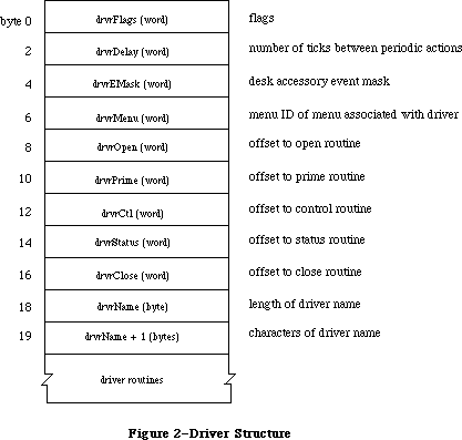 Figure 2–Driver Structure
For example, when a KillIO call is made to a driver, the driver’s control routine must implement the call.
Each bit of the high-order byte of the drvrFlags word contains a flag:
dReadEnable .EQU 0 ;set if driver can respond to Read calls
dWritEnable .EQU 1 ;set if driver can respond to Write calls
dCtlEnable .EQU 2 ;set if driver can respond to Control calls
dStatEnable .EQU 3 ;set if driver can respond to Status calls
dNeedGoodBye .EQU 4 ;set if driver needs to be called before
; the application heap is reinitialized
dNeedTime .EQU 5 ;set if driver needs time for performing
; a periodic action
dNeedLock .EQU 6 ;set if driver will be locked in memory as
; soon as it's opened (always set for ROM drivers)
Bits 8-11 (bits 0-3 of the high-order byte) indicate which Device Manager calls the driver’s routines can respond to.
Unlocked RAM drivers in the application heap will be lost every time the heap is reinitialized (when an application starts up, for example). If dNeedGoodBye is set, the control routine of the device driver will be called before the heap is reinitialized, and the driver can perform any “clean-up” actions it needs to. The driver’s control routine identifies this “good-bye” call by checking the csCode parameter—it will be the global constant
goodBye .EQU -1 ;heap will be reinitialized, clean up if necessary
Device drivers may need to perform predefined actions periodically. For example, a network driver may want to poll its input buffer every ten seconds to see if it has received any messages. If the dNeedTime flag is set, the driver does need to perform a periodic action, and the drvrDelay word contains a tick count indicating how often the periodic action should occur. A tick count of 0 means it should happen as often as possible, 1 means it should happen at most every sixtieth of a second, 2 means at most every thirtieth of a second, and so on. Whether the action actually occurs this frequently depends on how often the application calls the Desk Manager procedure SystemTask. SystemTask calls the driver’s control routine (if the time indicated by drvrDelay has elapsed), and the control routine must perform whatever predefined action is desired. The driver’s control routine identifies the SystemTask call by checking the csCode parameter—it will be the global constant
accRun .EQU 65 ;take the periodic action, if any, for this driver
Note: Some drivers may not want to rely on the application to call
SystemTask. The Vertical Retrace Manager and Time Manager both offer
the ability to perform tasks periodically. Both of these alternatives,
however, perform these tasks at interrupt time, and there are certain
restrictions on tasks performed during interrupts, such as not
being able to make calls to the Memory Manager. For more information
on these restrictions, see the Vertical Retrace Manager, and Time
Manager chapters. Tasks that are time consuming may be able to take
advantage of the Deferred Task Manager, which will allow other
interrupts to be processed. Periodic actions performed in response to
SystemTask calls are not performed via an interrupt and so don’t have
these restrictions.
DrvrEMask and drvrMenu are used only for desk accessories and are discussed in the Desk Manager chapter.
Following drvrMenu are the offsets to the driver routines, a title for the driver (preceded by its length in bytes), and the routines that do the work of the driver.
Note: Each of the driver routines must be aligned on a word boundary.
_______________________________________________________________________________
»Device Control Entry
The first time a driver is opened, information about it is read into a structure in memory called a device control entry. A device control entry contains the header of the driver’s I/O queue, the location of the driver’s routines, and other information. A device control entry is a 40-byte relocatable block located in the system heap. It’s locked while the driver is open, and unlocked while the driver is closed.
Most of the data in the device control entry is stored and accessed only by the Device Manager, but in some cases the driver itself must store into it. The structure of a device control entry is shown below; note that the first four words of the driver are copied into the dCtlFlags, dCtlDelay, dCtlEMask, and dCtlMenu fields.
TYPE DCtlEntry = RECORD
dCtlDriver: Ptr; {pointer to ROM driver or }
{ handle to RAM driver}
dCtlFlags: INTEGER; {flags}
dCtlQHdr: QHdr; {driver I/O queue header}
dCtlPosition: LONGINT; {byte position used by Read }
{ and Write calls}
dCtlStorage: Handle; {handle to RAM driver's }
{ private storage}
dCtlRefNum: INTEGER; {driver reference number}
dCtlCurTicks: LONGINT; {used internally}
dCtlWindow: WindowPtr; {pointer to driver's window}
dCtlDelay: INTEGER; {number of ticks between }
{ periodic actions}
dCtlEMask: INTEGER; {desk accessory event mask}
dCtlMenu: INTEGER {menu ID of menu associated
{ with driver}
END;
DCtlPtr = ^DCtlEntry;
DCtlHandle = ^DCtlPtr;
The low-order byte of the dCtlFlags word contains the following flags:
Bit number Meaning
5 Set if driver is open
6 Set if driver is RAM-based
7 Set if driver is currently executing
Assembly-language note: These flags can be accessed with the global
constants dOpened, dRAMBased, and drvrActive.
The high-order byte of the dCtlFlags word contains flags copied from the drvrFlags word of the driver, as described above.
DCtlQHdr contains the header of the driver’s I/O queue (described below). DCtlPosition is used only by drivers of block devices, and indicates the current source or destination position of a Read or Write call. The position is given as a number of bytes beyond the physical beginning of the medium used by the device. For example, if one logical block of data has just been read from a 3 1/2-inch disk via the Disk Driver, dCtlPosition will be 512.
ROM drivers generally use locations in low memory for their local storage. RAM drivers may reserve memory within their code space, or allocate a relocatable block and keep a handle to it in dCtlStorage (if the block resides in the application heap, its handle will be set to NIL when the heap is reinitialized).
You can get a handle to a driver’s device control entry by calling the Device Manager function GetDCtlEntry.
FUNCTION GetDCtlEntry (refNum: INTEGER) : DCtlHandle; [Not in ROM]
GetDCtlEntry returns a handle to the device control entry of the device driver having the reference number refNum.
Assembly-language note: You can get a handle to a driver’s device control
entry from the unit table, as described below.
_______________________________________________________________________________
»The Driver I/O Queue
Each device driver has a driver I/O queue; this is a standard Operating System queue (described in the Operating System Utilities chapter) that contains the parameter blocks for all asynchronous routines awaiting execution. Each time a routine is called, the driver places an entry in the queue; each time a routine is completed, its entry is removed from the queue. The queue’s header is located in the dCtlQHdr field of the driver’s device control entry. The low-order byte of the queue flags field in the queue header contains the version number of the driver, and can be used for distinguishing between different versions of the same driver.
Each entry in the driver I/O queue consists of a parameter block for the routine that was called. Most of the fields of this parameter block contain information needed by the specific Device Manager routines; these fields are explained above in the section “Low-Level Device Manager Routines”. The first four fields of this parameter block, shown below, are used by the Device Manager in processing the I/O requests in the queue.
TYPE ParamBlockRec = RECORD
qLink: QElemPtr; {next queue entry}
qType: INTEGER; {queue type}
ioTrap: INTEGER; {routine trap}
ioCmdAddr: Ptr; {routine address}
. . . {rest of block}
END;
QLink points to the next entry in the queue, and qType indicates the queue type, which must always be ORD(ioQType). IOTrap and ioCmdAddr contain the trap and address of the Device Manager routine that was called.
_______________________________________________________________________________
»The Unit Table
The location of each device control entry is maintained in a list called the unit table. The unit table is a 128-byte nonrelocatable block containing 32 four-byte entries. Each entry has a number, from 0 to 31, called the unit number, and contains a handle to the device control entry for a driver. The unit number can be used as an index into the unit table to locate the handle to a specific driver’s device control entry; it’s equal to
–1 * (refNum + 1)
where refNum is the driver reference number. For example, the Sound Driver’s reference number is –4 and its unit number is 3.
Figure 3 shows the layout of the unit table with the standard drivers and desk accessories installed.
Figure 2–Driver Structure
For example, when a KillIO call is made to a driver, the driver’s control routine must implement the call.
Each bit of the high-order byte of the drvrFlags word contains a flag:
dReadEnable .EQU 0 ;set if driver can respond to Read calls
dWritEnable .EQU 1 ;set if driver can respond to Write calls
dCtlEnable .EQU 2 ;set if driver can respond to Control calls
dStatEnable .EQU 3 ;set if driver can respond to Status calls
dNeedGoodBye .EQU 4 ;set if driver needs to be called before
; the application heap is reinitialized
dNeedTime .EQU 5 ;set if driver needs time for performing
; a periodic action
dNeedLock .EQU 6 ;set if driver will be locked in memory as
; soon as it's opened (always set for ROM drivers)
Bits 8-11 (bits 0-3 of the high-order byte) indicate which Device Manager calls the driver’s routines can respond to.
Unlocked RAM drivers in the application heap will be lost every time the heap is reinitialized (when an application starts up, for example). If dNeedGoodBye is set, the control routine of the device driver will be called before the heap is reinitialized, and the driver can perform any “clean-up” actions it needs to. The driver’s control routine identifies this “good-bye” call by checking the csCode parameter—it will be the global constant
goodBye .EQU -1 ;heap will be reinitialized, clean up if necessary
Device drivers may need to perform predefined actions periodically. For example, a network driver may want to poll its input buffer every ten seconds to see if it has received any messages. If the dNeedTime flag is set, the driver does need to perform a periodic action, and the drvrDelay word contains a tick count indicating how often the periodic action should occur. A tick count of 0 means it should happen as often as possible, 1 means it should happen at most every sixtieth of a second, 2 means at most every thirtieth of a second, and so on. Whether the action actually occurs this frequently depends on how often the application calls the Desk Manager procedure SystemTask. SystemTask calls the driver’s control routine (if the time indicated by drvrDelay has elapsed), and the control routine must perform whatever predefined action is desired. The driver’s control routine identifies the SystemTask call by checking the csCode parameter—it will be the global constant
accRun .EQU 65 ;take the periodic action, if any, for this driver
Note: Some drivers may not want to rely on the application to call
SystemTask. The Vertical Retrace Manager and Time Manager both offer
the ability to perform tasks periodically. Both of these alternatives,
however, perform these tasks at interrupt time, and there are certain
restrictions on tasks performed during interrupts, such as not
being able to make calls to the Memory Manager. For more information
on these restrictions, see the Vertical Retrace Manager, and Time
Manager chapters. Tasks that are time consuming may be able to take
advantage of the Deferred Task Manager, which will allow other
interrupts to be processed. Periodic actions performed in response to
SystemTask calls are not performed via an interrupt and so don’t have
these restrictions.
DrvrEMask and drvrMenu are used only for desk accessories and are discussed in the Desk Manager chapter.
Following drvrMenu are the offsets to the driver routines, a title for the driver (preceded by its length in bytes), and the routines that do the work of the driver.
Note: Each of the driver routines must be aligned on a word boundary.
_______________________________________________________________________________
»Device Control Entry
The first time a driver is opened, information about it is read into a structure in memory called a device control entry. A device control entry contains the header of the driver’s I/O queue, the location of the driver’s routines, and other information. A device control entry is a 40-byte relocatable block located in the system heap. It’s locked while the driver is open, and unlocked while the driver is closed.
Most of the data in the device control entry is stored and accessed only by the Device Manager, but in some cases the driver itself must store into it. The structure of a device control entry is shown below; note that the first four words of the driver are copied into the dCtlFlags, dCtlDelay, dCtlEMask, and dCtlMenu fields.
TYPE DCtlEntry = RECORD
dCtlDriver: Ptr; {pointer to ROM driver or }
{ handle to RAM driver}
dCtlFlags: INTEGER; {flags}
dCtlQHdr: QHdr; {driver I/O queue header}
dCtlPosition: LONGINT; {byte position used by Read }
{ and Write calls}
dCtlStorage: Handle; {handle to RAM driver's }
{ private storage}
dCtlRefNum: INTEGER; {driver reference number}
dCtlCurTicks: LONGINT; {used internally}
dCtlWindow: WindowPtr; {pointer to driver's window}
dCtlDelay: INTEGER; {number of ticks between }
{ periodic actions}
dCtlEMask: INTEGER; {desk accessory event mask}
dCtlMenu: INTEGER {menu ID of menu associated
{ with driver}
END;
DCtlPtr = ^DCtlEntry;
DCtlHandle = ^DCtlPtr;
The low-order byte of the dCtlFlags word contains the following flags:
Bit number Meaning
5 Set if driver is open
6 Set if driver is RAM-based
7 Set if driver is currently executing
Assembly-language note: These flags can be accessed with the global
constants dOpened, dRAMBased, and drvrActive.
The high-order byte of the dCtlFlags word contains flags copied from the drvrFlags word of the driver, as described above.
DCtlQHdr contains the header of the driver’s I/O queue (described below). DCtlPosition is used only by drivers of block devices, and indicates the current source or destination position of a Read or Write call. The position is given as a number of bytes beyond the physical beginning of the medium used by the device. For example, if one logical block of data has just been read from a 3 1/2-inch disk via the Disk Driver, dCtlPosition will be 512.
ROM drivers generally use locations in low memory for their local storage. RAM drivers may reserve memory within their code space, or allocate a relocatable block and keep a handle to it in dCtlStorage (if the block resides in the application heap, its handle will be set to NIL when the heap is reinitialized).
You can get a handle to a driver’s device control entry by calling the Device Manager function GetDCtlEntry.
FUNCTION GetDCtlEntry (refNum: INTEGER) : DCtlHandle; [Not in ROM]
GetDCtlEntry returns a handle to the device control entry of the device driver having the reference number refNum.
Assembly-language note: You can get a handle to a driver’s device control
entry from the unit table, as described below.
_______________________________________________________________________________
»The Driver I/O Queue
Each device driver has a driver I/O queue; this is a standard Operating System queue (described in the Operating System Utilities chapter) that contains the parameter blocks for all asynchronous routines awaiting execution. Each time a routine is called, the driver places an entry in the queue; each time a routine is completed, its entry is removed from the queue. The queue’s header is located in the dCtlQHdr field of the driver’s device control entry. The low-order byte of the queue flags field in the queue header contains the version number of the driver, and can be used for distinguishing between different versions of the same driver.
Each entry in the driver I/O queue consists of a parameter block for the routine that was called. Most of the fields of this parameter block contain information needed by the specific Device Manager routines; these fields are explained above in the section “Low-Level Device Manager Routines”. The first four fields of this parameter block, shown below, are used by the Device Manager in processing the I/O requests in the queue.
TYPE ParamBlockRec = RECORD
qLink: QElemPtr; {next queue entry}
qType: INTEGER; {queue type}
ioTrap: INTEGER; {routine trap}
ioCmdAddr: Ptr; {routine address}
. . . {rest of block}
END;
QLink points to the next entry in the queue, and qType indicates the queue type, which must always be ORD(ioQType). IOTrap and ioCmdAddr contain the trap and address of the Device Manager routine that was called.
_______________________________________________________________________________
»The Unit Table
The location of each device control entry is maintained in a list called the unit table. The unit table is a 128-byte nonrelocatable block containing 32 four-byte entries. Each entry has a number, from 0 to 31, called the unit number, and contains a handle to the device control entry for a driver. The unit number can be used as an index into the unit table to locate the handle to a specific driver’s device control entry; it’s equal to
–1 * (refNum + 1)
where refNum is the driver reference number. For example, the Sound Driver’s reference number is –4 and its unit number is 3.
Figure 3 shows the layout of the unit table with the standard drivers and desk accessories installed.
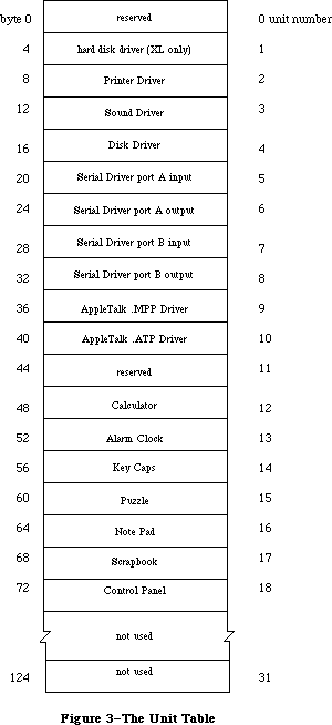 Figure 3–The Unit Table
Warning: Any new drivers contained in resource files should have resource
IDs that don’t conflict with the unit numbers of existing
drivers—unless you want an existing driver to be replaced. Be
sure to check the unit table before installing a new driver;
the base address of the unit table is stored in the global
variable UTableBase.
X-Ref: Technical Note #71
_______________________________________________________________________________
»WRITING YOUR OWN DEVICE DRIVERS
_______________________________________________________________________________
Drivers are usually written in assembly language. The structure of your driver must match that shown in the previous section. The routines that do the work of the driver should be written to operate the device in whatever way you require. Your driver must contain routines to handle Open and Close calls, and may choose to handle Read, Write, Control, Status, and KillIO calls as well.
Warning: A device driver doesn’t “own” the hardware it operates, and has
no way of determining whether another driver is attempting to
use that hardware at the same time. There’s a possiblity of
conflict in situations where two drivers that operate the same
device are installed concurrently.
When the Device Manager executes a driver routine to handle an application call, it passes a pointer to the call’s parameter block in register A0 and a pointer to the driver’s device control entry in register A1. From this information, the driver can determine exactly what operations are required to fulfill the call’s requests, and do them.
Open and close routines must execute synchronously and return via an RTS instruction. They needn’t preserve any registers that they use. Close routines should put a result code in register D0. Since the Device Manager sets D0 to 0 upon return from an Open call, open routines should instead place the result code in the ioResult field of the parameter block.
The open routine must allocate any private storage required by the driver, store a handle to it in the device control entry (in the dCtlStorage field), initialize any local variables, and then be ready to receive a Read, Write, Status, Control, or KillIO call. It might also install interrupt handlers, change interrupt vectors, and store a pointer to the device control entry somewhere in its local storage for its interrupt handlers to use. The close routine must reverse the effects of the open routine, by releasing all used memory, removing interrupt handlers, and replacing changed interrupt vectors. If anything about the operational state of the driver should be saved until the next time the driver is opened, it should be kept in the relocatable block of memory pointed to by dCtlStorage.
Prime, control, and status routines must be able to respond to queued calls and asynchronous calls, and should be interrupt-driven. Asynchronous portions of the routines can use registers A0-A3 and D0-D3, but must preserve any other registers used; synchronous portions can use all registers. Prime, control, and status routines should return a result code in D0. They must return via an RTS if called immediately (with noQueueBit set in the ioTrap field) or if the device couldn’t complete the I/O request right away, or via a JMP to the IODone routine (explained below) if not called immediately and if the device completed the request.
Warning: If the prime, control, and status routines can be called as the
result of an interrupt, they must preserve all registers other
than A0, A1, and D0-D2. They can’t make any calls to the Memory
Manager and cannot depend on unlocked handles being valid. If
they use application globals, they must also ensure that register
A5 contains the address of the boundary between the application
globals and the application parameters; for details, refer to
SetCurrentA5 and SetA5 in Macintosh Technical Note #208.
X-Ref: Technical Note #208
The prime routine implements Read and Write calls made to the driver. It can distinguish between Read and Write calls by comparing the low-order byte of the ioTrap field with the following predefined constants:
aRdCmd .EQU 2 ;Read call
aWrCmd .EQU 3 ;Write call
You may want to use the Fetch and Stash routines (described below) to read and write characters. If the driver is for a block device, it should update the dCtlPosition field of the device control entry after each read or write.
The control routine accepts the control information passed to it, and manipulates the device as requested. The status routine returns requested status information. Since both the control and status routines may be subjected to Control and Status calls sending and requesting a variety of information, they must be prepared to respond correctly to all types. The control routine must handle KillIO calls. The driver identifies KillIO calls by checking the csCode parameter—it will be the global constant
killCode .EQU 1 ;handle the KillIO call
Warning: KillIO calls must return via an RTS, and shouldn’t jump
(via JMP) to the IODone routine.
_______________________________________________________________________________
»Routines for Writing Drivers
The Device Manager includes three routines—Fetch, Stash, and IODone—that provide low-level support for driver routines. These routines can be used only with a pending, asynchronous request; include them in the code of your device driver if they’re useful to you. A pointer to the device control entry is passed to each of these routines in register A1. The device control entry contains the driver I/O queue header, which is used to locate the pending request. If there are no pending requests, these routines generate the system error dsIOCoreErr (see the System Error Handler chapter for more information).
X-Ref: Technical Note #36
X-Ref: Technical Note #108
X-Ref: Technical Note #187
X-Ref: Technical Note #257
X-Ref: Q & A Stack
Fetch, Stash, and IODone are invoked via “jump vectors” (stored in the global variables JFetch, JStash, and JIODone) rather than macros, in the interest of speed. You use a jump vector by moving its address onto the stack. For example:
MOVE.L JIODone,-(SP)
RTS
Fetch and Stash don’t return a result code; if an error occurs, the System Error Handler is invoked. IODone may return a result code.
Fetch function
Jump vector JFetch
On entry A1: pointer to device control entry
On exit D0: character fetched; bit 15=1 if it’s the last
character in data buffer
Fetch gets the next character from the data buffer pointed to by ioBuffer and places it in D0. IOActCount is incremented by 1. If ioActCount equals ioReqCount, bit 15 of D0 is set. After receiving the last byte requested, the driver should call IODone.
Stash function
Jump vector JStash
On entry A1: pointer to device control entry
D0: character to stash
On exit D0: bit 15=1 if it’s the last character requested
Stash places the character in D0 into the data buffer pointed to by ioBuffer, and increments ioActCount by 1. If ioActCount equals ioReqCount, bit 15 of D0 is set. After stashing the last byte requested, the driver should call IODone.
IODone function
Jump vector JIODone
On entry A1: pointer to device control entry
D0: result code (word)
IODone removes the current I/O request from the driver I/O queue, marks the driver inactive, unlocks the driver and its device control entry (if it’s allowed to by the dNeedLock bit of the dCtlFlags word), and executes the completion routine (if there is one). Then it begins executing the next I/O request in the driver I/O queue.
Warning: Due to the way the File Manager does directory lookups, block
device drivers should take care to support asynchronous I/O
operations. If the driver’s prime routine has completed an
asynchronous Read or Write call just prior to calling IODone
and its completion routine starts an additional Read or Write,
large amounts of the stack may be used (potentially causing the
stack to expand into the heap). To avoid this problem, the prime
routine should exit via an RTS instruction and then jump to IODone
via an interrupt.
_______________________________________________________________________________
»INTERRUPTS
_______________________________________________________________________________
This section discusses how interrupts are used on the Macintosh 128K and 512K specifically. The general philosophy applies to all Macintosh computers. Only programmers who want to write interrupt-driven device drivers need read this section.
Warning: Only the Macintosh 128K and 512K are covered in this section.
Much of the information presented here is hardware-dependent;
programmers are encouraged to write code that’s hardware-independent
to ensure compatibility with future versions of the Macintosh.
An interrupt is a form of exception: an error or abnormal condition detected by the processor in the course of program execution. Specifically, an interrupt is an exception that’s signaled to the processor by a device, as distinct from a trap, which arises directly from the execution of an instruction. Interrupts are used by devices to notify the processor of a change in condition of the device, such as the completion of an I/O request. An interrupt causes the processor to suspend normal execution, save the address of the next instruction and the processor’s internal status on the stack, and execute an interrupt handler.
The MC68000 recognizes seven different levels of interrupt, each with its own interrupt handler. The addresses of the various handlers, called interrupt vectors, are kept in a vector table in low memory. Each level of interrupt has its own vector located in the vector table. When an interrupt occurs, the processor fetches the proper vector from the table, uses it to locate the interrupt handler for that level of interrupt, and jumps to the handler. On completion, the handler restores the internal status of the processor from the stack and resumes normal execution from the point of suspension.
There are three devices that can create interrupts: the Synertek SY6522 Versatile Interface Adapter (VIA), the Zilog Z8530 Serial Communications Controller (SCC), and the debugging switch. They send a three-bit number called the interrupt priority level to the processor. This number indicates which device is interrupting, and which interrupt handler should be executed:
Level Interrupting device
0 None
1 VIA
2 SCC
3 VIA and SCC
4-7 Debugging switch
A level-3 interrupt occurs when both the VIA and the SCC interrupt at the same instant; the interrupt handler for a level-3 interrupt is simply an RTE instruction. Debugging interrupts shouldn’t occur during the normal execution of an application.
The interrupt priority level is compared with the processor priority in bits
8-10 of the status register. If the interrupt priority level is greater than the processor priority, the MC68000 acknowledges the interrupt and initiates interrupt processing. The processor priority determines which interrupting devices are ignored, and which are serviced:
Level Services
0 All interrupts
1 SCC and debugging interrupts only
2-6 Debugging interrupts only
7 No interrupts
When an interrupt is acknowledged, the processor priority is set to the interrupt priority level, to prevent additional interrupts of equal or lower priority, until the interrupt handler has finished servicing the interrupt.
The interrupt priority level is used as an index into the primary interrupt vector table. This table contains seven long words beginning at address $64. Each long word contains the starting address of an interrupt handler (see Figure 4).
Execution jumps to the interrupt handler at the address specified in the table. The interrupt handler must identify and service the interrupt. Then it must restore the processor priority, status register, and program counter to the values they contained before the interrupt occurred.
Figure 3–The Unit Table
Warning: Any new drivers contained in resource files should have resource
IDs that don’t conflict with the unit numbers of existing
drivers—unless you want an existing driver to be replaced. Be
sure to check the unit table before installing a new driver;
the base address of the unit table is stored in the global
variable UTableBase.
X-Ref: Technical Note #71
_______________________________________________________________________________
»WRITING YOUR OWN DEVICE DRIVERS
_______________________________________________________________________________
Drivers are usually written in assembly language. The structure of your driver must match that shown in the previous section. The routines that do the work of the driver should be written to operate the device in whatever way you require. Your driver must contain routines to handle Open and Close calls, and may choose to handle Read, Write, Control, Status, and KillIO calls as well.
Warning: A device driver doesn’t “own” the hardware it operates, and has
no way of determining whether another driver is attempting to
use that hardware at the same time. There’s a possiblity of
conflict in situations where two drivers that operate the same
device are installed concurrently.
When the Device Manager executes a driver routine to handle an application call, it passes a pointer to the call’s parameter block in register A0 and a pointer to the driver’s device control entry in register A1. From this information, the driver can determine exactly what operations are required to fulfill the call’s requests, and do them.
Open and close routines must execute synchronously and return via an RTS instruction. They needn’t preserve any registers that they use. Close routines should put a result code in register D0. Since the Device Manager sets D0 to 0 upon return from an Open call, open routines should instead place the result code in the ioResult field of the parameter block.
The open routine must allocate any private storage required by the driver, store a handle to it in the device control entry (in the dCtlStorage field), initialize any local variables, and then be ready to receive a Read, Write, Status, Control, or KillIO call. It might also install interrupt handlers, change interrupt vectors, and store a pointer to the device control entry somewhere in its local storage for its interrupt handlers to use. The close routine must reverse the effects of the open routine, by releasing all used memory, removing interrupt handlers, and replacing changed interrupt vectors. If anything about the operational state of the driver should be saved until the next time the driver is opened, it should be kept in the relocatable block of memory pointed to by dCtlStorage.
Prime, control, and status routines must be able to respond to queued calls and asynchronous calls, and should be interrupt-driven. Asynchronous portions of the routines can use registers A0-A3 and D0-D3, but must preserve any other registers used; synchronous portions can use all registers. Prime, control, and status routines should return a result code in D0. They must return via an RTS if called immediately (with noQueueBit set in the ioTrap field) or if the device couldn’t complete the I/O request right away, or via a JMP to the IODone routine (explained below) if not called immediately and if the device completed the request.
Warning: If the prime, control, and status routines can be called as the
result of an interrupt, they must preserve all registers other
than A0, A1, and D0-D2. They can’t make any calls to the Memory
Manager and cannot depend on unlocked handles being valid. If
they use application globals, they must also ensure that register
A5 contains the address of the boundary between the application
globals and the application parameters; for details, refer to
SetCurrentA5 and SetA5 in Macintosh Technical Note #208.
X-Ref: Technical Note #208
The prime routine implements Read and Write calls made to the driver. It can distinguish between Read and Write calls by comparing the low-order byte of the ioTrap field with the following predefined constants:
aRdCmd .EQU 2 ;Read call
aWrCmd .EQU 3 ;Write call
You may want to use the Fetch and Stash routines (described below) to read and write characters. If the driver is for a block device, it should update the dCtlPosition field of the device control entry after each read or write.
The control routine accepts the control information passed to it, and manipulates the device as requested. The status routine returns requested status information. Since both the control and status routines may be subjected to Control and Status calls sending and requesting a variety of information, they must be prepared to respond correctly to all types. The control routine must handle KillIO calls. The driver identifies KillIO calls by checking the csCode parameter—it will be the global constant
killCode .EQU 1 ;handle the KillIO call
Warning: KillIO calls must return via an RTS, and shouldn’t jump
(via JMP) to the IODone routine.
_______________________________________________________________________________
»Routines for Writing Drivers
The Device Manager includes three routines—Fetch, Stash, and IODone—that provide low-level support for driver routines. These routines can be used only with a pending, asynchronous request; include them in the code of your device driver if they’re useful to you. A pointer to the device control entry is passed to each of these routines in register A1. The device control entry contains the driver I/O queue header, which is used to locate the pending request. If there are no pending requests, these routines generate the system error dsIOCoreErr (see the System Error Handler chapter for more information).
X-Ref: Technical Note #36
X-Ref: Technical Note #108
X-Ref: Technical Note #187
X-Ref: Technical Note #257
X-Ref: Q & A Stack
Fetch, Stash, and IODone are invoked via “jump vectors” (stored in the global variables JFetch, JStash, and JIODone) rather than macros, in the interest of speed. You use a jump vector by moving its address onto the stack. For example:
MOVE.L JIODone,-(SP)
RTS
Fetch and Stash don’t return a result code; if an error occurs, the System Error Handler is invoked. IODone may return a result code.
Fetch function
Jump vector JFetch
On entry A1: pointer to device control entry
On exit D0: character fetched; bit 15=1 if it’s the last
character in data buffer
Fetch gets the next character from the data buffer pointed to by ioBuffer and places it in D0. IOActCount is incremented by 1. If ioActCount equals ioReqCount, bit 15 of D0 is set. After receiving the last byte requested, the driver should call IODone.
Stash function
Jump vector JStash
On entry A1: pointer to device control entry
D0: character to stash
On exit D0: bit 15=1 if it’s the last character requested
Stash places the character in D0 into the data buffer pointed to by ioBuffer, and increments ioActCount by 1. If ioActCount equals ioReqCount, bit 15 of D0 is set. After stashing the last byte requested, the driver should call IODone.
IODone function
Jump vector JIODone
On entry A1: pointer to device control entry
D0: result code (word)
IODone removes the current I/O request from the driver I/O queue, marks the driver inactive, unlocks the driver and its device control entry (if it’s allowed to by the dNeedLock bit of the dCtlFlags word), and executes the completion routine (if there is one). Then it begins executing the next I/O request in the driver I/O queue.
Warning: Due to the way the File Manager does directory lookups, block
device drivers should take care to support asynchronous I/O
operations. If the driver’s prime routine has completed an
asynchronous Read or Write call just prior to calling IODone
and its completion routine starts an additional Read or Write,
large amounts of the stack may be used (potentially causing the
stack to expand into the heap). To avoid this problem, the prime
routine should exit via an RTS instruction and then jump to IODone
via an interrupt.
_______________________________________________________________________________
»INTERRUPTS
_______________________________________________________________________________
This section discusses how interrupts are used on the Macintosh 128K and 512K specifically. The general philosophy applies to all Macintosh computers. Only programmers who want to write interrupt-driven device drivers need read this section.
Warning: Only the Macintosh 128K and 512K are covered in this section.
Much of the information presented here is hardware-dependent;
programmers are encouraged to write code that’s hardware-independent
to ensure compatibility with future versions of the Macintosh.
An interrupt is a form of exception: an error or abnormal condition detected by the processor in the course of program execution. Specifically, an interrupt is an exception that’s signaled to the processor by a device, as distinct from a trap, which arises directly from the execution of an instruction. Interrupts are used by devices to notify the processor of a change in condition of the device, such as the completion of an I/O request. An interrupt causes the processor to suspend normal execution, save the address of the next instruction and the processor’s internal status on the stack, and execute an interrupt handler.
The MC68000 recognizes seven different levels of interrupt, each with its own interrupt handler. The addresses of the various handlers, called interrupt vectors, are kept in a vector table in low memory. Each level of interrupt has its own vector located in the vector table. When an interrupt occurs, the processor fetches the proper vector from the table, uses it to locate the interrupt handler for that level of interrupt, and jumps to the handler. On completion, the handler restores the internal status of the processor from the stack and resumes normal execution from the point of suspension.
There are three devices that can create interrupts: the Synertek SY6522 Versatile Interface Adapter (VIA), the Zilog Z8530 Serial Communications Controller (SCC), and the debugging switch. They send a three-bit number called the interrupt priority level to the processor. This number indicates which device is interrupting, and which interrupt handler should be executed:
Level Interrupting device
0 None
1 VIA
2 SCC
3 VIA and SCC
4-7 Debugging switch
A level-3 interrupt occurs when both the VIA and the SCC interrupt at the same instant; the interrupt handler for a level-3 interrupt is simply an RTE instruction. Debugging interrupts shouldn’t occur during the normal execution of an application.
The interrupt priority level is compared with the processor priority in bits
8-10 of the status register. If the interrupt priority level is greater than the processor priority, the MC68000 acknowledges the interrupt and initiates interrupt processing. The processor priority determines which interrupting devices are ignored, and which are serviced:
Level Services
0 All interrupts
1 SCC and debugging interrupts only
2-6 Debugging interrupts only
7 No interrupts
When an interrupt is acknowledged, the processor priority is set to the interrupt priority level, to prevent additional interrupts of equal or lower priority, until the interrupt handler has finished servicing the interrupt.
The interrupt priority level is used as an index into the primary interrupt vector table. This table contains seven long words beginning at address $64. Each long word contains the starting address of an interrupt handler (see Figure 4).
Execution jumps to the interrupt handler at the address specified in the table. The interrupt handler must identify and service the interrupt. Then it must restore the processor priority, status register, and program counter to the values they contained before the interrupt occurred.
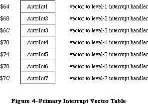 Figure 4–Primary Interrupt Vector Table
_______________________________________________________________________________
»Level-1 (VIA) Interrupts
Level-1 interrupts are generated by the VIA. You’ll need to read the Synertek manual describing the VIA to use most of the information provided in this section. The level-1 interrupt handler determines the source of the interrupt
(via the VIA’s interrupt flag register and interrupt enable register) and then uses a table of secondary vectors in low memory to determine which interrupt handler to call (see Figure 5).
Figure 4–Primary Interrupt Vector Table
_______________________________________________________________________________
»Level-1 (VIA) Interrupts
Level-1 interrupts are generated by the VIA. You’ll need to read the Synertek manual describing the VIA to use most of the information provided in this section. The level-1 interrupt handler determines the source of the interrupt
(via the VIA’s interrupt flag register and interrupt enable register) and then uses a table of secondary vectors in low memory to determine which interrupt handler to call (see Figure 5).
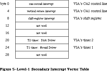 Figure 5–Level-1 Secondary Interrupt Vector Table
The level-1 secondary interrupt vector table is stored in the global variable Lvl1DT. Each vector in the table points to the interrupt handler for a different source of interrupt. The interrupts are handled in order of their entry in the table, and only one interrupt handler is called per level-1 interrupt (even if two or more sources are interrupting). This allows the
level-1 interrupt handler to be reentrant; interrupt handlers should lower the processor priority as soon as possible in order to enable other pending interrupts to be processed.
The one-second interrupt updates the global variable Time (explained in the Operating System Utilities chapter); it’s also used for inverting (“blinking”) the apple symbol in the menu bar when the alarm goes off. Vertical retrace interrupts are generated once every vertical retrace interval; control is passed to the Vertical Retrace Manager, which performs recurrent system tasks
(such as updating the global variable Ticks) and executes tasks installed by the application. (For more information, see the Vertical Retrace Manager chapter.)
If the cumulative elapsed time for all tasks during a vertical retrace interrupt exceeds about 16 milliseconds (one video frame), the vertical retrace interrupt may itself be interrupted by another vertical retrace interrupt. In this case, tasks to be performed during the second vertical retrace interrupt are ignored, with one exception: The global variable Ticks will still be updated.
The shift-register interrupt is used by the keyboard and mouse interrupt handlers. Whenever the Disk Driver or Sound Driver isn’t being used, you can use the T1 and T2 timers for your own needs; there’s no way to tell, however, when they’ll be needed again by the Disk Driver or Sound Driver.
The base address of the VIA (stored in the global variable VIA) is passed to each interrupt handler in register A1.
_______________________________________________________________________________
»Level-2 (SCC) Interrupts
Level-2 interrupts are generated by the SCC. You’ll need to read the Zilog manual describing the SCC to effectively use the information provided in this section. The level-2 interrupt handler determines the source of the interrupt, and then uses a table of secondary vectors in low memory to determine which interrupt handler to call (see Figure 6).
Figure 5–Level-1 Secondary Interrupt Vector Table
The level-1 secondary interrupt vector table is stored in the global variable Lvl1DT. Each vector in the table points to the interrupt handler for a different source of interrupt. The interrupts are handled in order of their entry in the table, and only one interrupt handler is called per level-1 interrupt (even if two or more sources are interrupting). This allows the
level-1 interrupt handler to be reentrant; interrupt handlers should lower the processor priority as soon as possible in order to enable other pending interrupts to be processed.
The one-second interrupt updates the global variable Time (explained in the Operating System Utilities chapter); it’s also used for inverting (“blinking”) the apple symbol in the menu bar when the alarm goes off. Vertical retrace interrupts are generated once every vertical retrace interval; control is passed to the Vertical Retrace Manager, which performs recurrent system tasks
(such as updating the global variable Ticks) and executes tasks installed by the application. (For more information, see the Vertical Retrace Manager chapter.)
If the cumulative elapsed time for all tasks during a vertical retrace interrupt exceeds about 16 milliseconds (one video frame), the vertical retrace interrupt may itself be interrupted by another vertical retrace interrupt. In this case, tasks to be performed during the second vertical retrace interrupt are ignored, with one exception: The global variable Ticks will still be updated.
The shift-register interrupt is used by the keyboard and mouse interrupt handlers. Whenever the Disk Driver or Sound Driver isn’t being used, you can use the T1 and T2 timers for your own needs; there’s no way to tell, however, when they’ll be needed again by the Disk Driver or Sound Driver.
The base address of the VIA (stored in the global variable VIA) is passed to each interrupt handler in register A1.
_______________________________________________________________________________
»Level-2 (SCC) Interrupts
Level-2 interrupts are generated by the SCC. You’ll need to read the Zilog manual describing the SCC to effectively use the information provided in this section. The level-2 interrupt handler determines the source of the interrupt, and then uses a table of secondary vectors in low memory to determine which interrupt handler to call (see Figure 6).
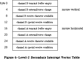 Figure 6–Level-2 Secondary Interrupt Vector Table
The level-2 secondary interrupt vector table is stored in the global variable Lvl2DT. Each vector in the table points to the interrupt handler for a different source of interrupt. The interrupts are handled according to the following fixed priority:
channel A receive character available and special receive
channel A transmit buffer empty
channel A external/status change
channel B receive character available and special receive
channel B transmit buffer empty
channel B external/status change
Only one interrupt handler is called per level-2 interrupt (even if two or more sources are interrupting). This allows the level-2 interrupt handler to be reentrant; interrupt handlers should lower the processor priority as soon as possible in order to enable other pending interrupts to be processed.
External/status interrupts pass through a tertiary vector table in low memory to determine which interrupt handler to call (see Figure 7).
Figure 6–Level-2 Secondary Interrupt Vector Table
The level-2 secondary interrupt vector table is stored in the global variable Lvl2DT. Each vector in the table points to the interrupt handler for a different source of interrupt. The interrupts are handled according to the following fixed priority:
channel A receive character available and special receive
channel A transmit buffer empty
channel A external/status change
channel B receive character available and special receive
channel B transmit buffer empty
channel B external/status change
Only one interrupt handler is called per level-2 interrupt (even if two or more sources are interrupting). This allows the level-2 interrupt handler to be reentrant; interrupt handlers should lower the processor priority as soon as possible in order to enable other pending interrupts to be processed.
External/status interrupts pass through a tertiary vector table in low memory to determine which interrupt handler to call (see Figure 7).
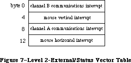 Figure 7–Level-2 External/Status Interrupt Vector Table
The external/status interrupt vector table is stored in the global variable ExtStsDT. Each vector in the table points to the interrupt handler for a different source of interrupt. Communications interrupts (break/abort, for example) are always handled before mouse interrupts.
When a level-2 interrupt handler is called, D0 contains the address of the SCC read register 0 (external/status interrupts only), and D1 contains the bits of read register 0 that have changed since the last external/status interrupt. A0 points to the SCC channel A or channel B control read address and A1 points to SCC channel A or channel B control write address, depending on which channel is interrupting. The SCC’s data read address and data write address are located four bytes beyond A0 and A1, respectively; they’re also contained in the global variables SCCWr and SCCRd. You can use the following predefined constants as offsets from these base addresses to locate the SCC control and data lines:
aData .EQU 6 ;channel A data in or out
aCtl .EQU 2 ;channel A control
bData .EQU 4 ;channel B data in or out
bCtl .EQU 0 ;channel B control
_______________________________________________________________________________
»Writing Your Own Interrupt Handlers
You can write your own interrupt handlers to replace any of the standard interrupt handlers just described. Be sure to place a vector that points to your interrupt handler in one of the vector tables.
Both the level-1 and level-2 interrupt handlers preserve registers A0-A3 and
D0-D3. Every interrupt handler (except for external/status interrupt handlers) is responsible for clearing the source of the interrupt, and for saving and restoring any additional registers used. Interrupt handlers should return directly via an RTS instruction, unless the interrupt is completing an asynchronous call, in which case they should jump (via JMP) to the IODone routine.
_______________________________________________________________________________
»THE CHOOSER
_______________________________________________________________________________
Note: The extensions to the Device Manager described in the following
section were originally documented in Inside Macintosh, Volume IV.
As such, this information refers to the 128K ROMs and System file
version 3.2 and later.
The Chooser is a desk accessory that provides a standard interface to help solicit and accept specific choices from the user. It allows new device drivers to prompt the user for choices such as which serial port to use, which AppleTalk zone to communicate with, and which LaserWriter to use.
The Chooser relies heavily on the List Manager for creating, displaying, and manipulating possible user selections. The List Manager is described in the List Manager chapter.
Under the Chooser, each device is represented by a device resource file in the system folder on the user’s system startup disk. (This is an extension of the concept of printer resource files, described in the Printing Manager chapter.) The Chooser accepts three types of device resource files to identify different kinds of devices:
File type Device type
'PRES' Serial printer
'PRER' Non-serial printer
'RDEV' Other device
The creator of each file is left undefined, allowing each device to have its own icon.
In addition to any actual driver code, each device resource file of type 'PRER' or 'RDEV' contains a set of resources that tell the Chooser how to handle the device. These resources include:
Resource type Resource ID Description
'PACK' –4096 Device package (described below)
'STR ' –4096 Type name for AppleTalk devices
'GNRL' –4096 NBP timeout and retry information
for AppleTalk devices
'STR ' –4093 Left button title
'STR ' –4092 Right button title
'STR ' –4091 String for Chooser to use to label
the list when choosing the device
'BNDL' Icon information
'STR ' –4090 Reserved for use by the Chooser
Warning: You should give your device type a distinctive icon, since this
may be the only way that devices are identified in the Chooser’s
screen display.
Device resource files of type 'PRES' (serial printers) contain only the driver code, without any of the resources listed above. The configuration of such devices is implemented entirely by the Chooser.
_______________________________________________________________________________
»The Device Package
The device package is usually written in assembly language, but may be written partially in Pascal. The assembly-language structure of the 'PACK' –4096 resource is as follows:
Offset (hex) Word
0 BRA.S to offset $10
2 Device ID (word)
4 'PACK' (long word)
8 $F000 (–4096)
A Version (word)
C Flags (long word)
10 Start of driver code
The device ID is an integer that identifies the device. The version word differentiates versions of the driver code. The flags field contains the following information:
Bit Meaning
31 Set if an AppleTalk device
30–29 Reserved (clear to 0)
28 Set if device package can have multiple instances selected at once
27 Set if device package uses left button
26 Set if device package uses right button
25 Set if no saved zone name
24 Set if device package uses actual zone names
23–17 Reserved (clear to 0)
16 Set if device package accepts the newSel message
15 Set if device package accepts the fillList message
14 Set if device package accepts the getSel message
13 Set if device package accepts the select message
12 Set if device package accepts the deselect message
11 Set if device package accepts the terminate message
10–0 Reserved (clear to 0)
_______________________________________________________________________________
»Communication with the Chooser
The Chooser communicates with device packages as if they were the following function:
FUNCTION Device (message,caller: INTEGER; objName,zoneName: StringPtr;
p1,p2: LONGINT) : OSErr;
The message parameter identifies the operation to be performed. It has one of the following values:
CONST newSelMsg = 12; {new user selections have been made}
fillListMsg = 13; {fill the list with choices to be made}
getSelMsg = 14; {mark one or more choices as selected}
selectMsg = 15; {a choice has actually been made}
deselectMsg = 16; {a choice has been cancelled}
terminateMsg = 17; {lets device package clean up}}
buttonMsg = 19; {tells driver a button has been selected}
The device package should always return noErr, except with select and deselect; with these messages, a result code other than noErr prevents selection or deselection from occurring. The device package must ignore any other messages in the range 0..127 and return noErr. If the message is selectMsg or deselectMsg, it may not call the List Manager.
The caller parameter identifies the caller as the Chooser, with a value of 1. Values in the range 0..127 are reserved; values outside this range may be used by applications.
For AppleTalk devices, the zoneName parameter is a pointer to a string of up to 32 characters containing the name of the AppleTalk zone in which the devices can be found. If the Chooser is being used with the local zone and bit 24 of the Flags field of the 'PACK' –4096 resource is clear, the string value is '*'; otherwise it’s the actual zone name.
The p1 parameter is a handle to a List Manager list of choices for a particular device; this device list must be filled by the device package in response to the fillListMsg message.
Other details of the Chooser messages and their parameters are given below.
»The NewSelMsg Parameter
The Chooser sends the newSel message (instead of the select or deselect message) only to device packages that allow multiple selections, when the user changes the selection.
The objName and p2 parameters are not used.
»The FillListMsg Parameter
When the Chooser sends the fillList message, the device package should fill a List Manager list filled with choices for a particular device; the p1 parameter is a handle to this list.
The objName and p2 parameters are not used.
»The GetSelMsg Parameter
When the Chooser sends the getSel message the device package should mark one or more choices in the given list as currently selected, by a call to LSetSelect.
The objName and p2 parameters are not used.
»The SelectMsg Parameter
The Chooser sends the select message whenever a particular choice has become selected, but only to device packages that do not allow multiple selections. The device package may not call the List Manager.
If the device accepts fillList messages, objName is undefined. Otherwise, the objName parameter is a pointer to a string of up to 32 characters containing the name of the device.
If the device accepts fillList messages, p2 gives the row number of the list that has become selected; otherwise (if the device is an AppleTalk device) p2 gives the AddrBlock value for the address of the AppleTalk device that has just become selected.
»The DeselectMsg Parameter
The Chooser sends the deselect message whenever a particular choice has become deselected, but only to device packages that do not allow multiple selections. The device package may not call the List Manager.
If the device accepts fillList messages, objName is undefined. Otherwise, the objName parameter is a pointer to a string of up to 32 characters containing the name of the device.
If the device accepts fillList messages, p2 gives the row number of the list that has become deselected; otherwise (if the device is an AppleTalk device) p2 gives the AddrBlock value for the address of the AppleTalk device that has just become deselected.
»The TerminateMsg Parameter
The Chooser sends the terminate message when the user selects a different device icon, closes the Chooser window, or changes zones. It allows the device package to perform cleanup tasks, if necessary. The device package should not dispose of the device list.
The objName and p2 parameters are not used.
»The ButtonMsg Parameter
The Chooser sends the button message when a button in the Chooser display has been clicked.
The low-order byte of the p2 parameter has a value of 1 if the left button has been clicked and 2 if the right button has been clicked.
The objName parameter is not used.
_______________________________________________________________________________
»Operation of the Chooser
When the Chooser is first selected from the desk accessory menu, it searches the system folder of the startup disk for device resource files—that is, resource files of type 'PRER', 'PRES', or 'RDEV'. For each one that it finds, it opens the file, fetches the device’s icon, fetches the flags long word from the device package, and closes the file. The Chooser then takes the following actions for each device, based on the information just retrieved:
• It displays the device’s icon in the Chooser’s window.
• If the device is an AppleTalk device and AppleTalk is not connected,
the Chooser grays the device’s icon.
When the user selects a device icon that is not grayed, the Chooser reopens the corresponding device resource file. It then does the following:
• If the device is type 'PRER' or 'PRES', it sets the current
printer type to that device.
• It labels the device’s list box with the string in the resource
'STR ' with an ID of –4091.
• If the device is a local printer, the Chooser fills its list box
with the two icons for the printer port and modem port serial drivers.
Later it will record the user’s choice in low memory and parameter RAM.
• If the device accepts fillList messages, the Chooser calls the device
package, which should fill column 0 of the list pointed to by p1 with
the names (without length bytes) of all available devices in the zone.
• If the device is an AppleTalk device that does not accept fillList
messages, the Chooser initiates an asynchronous routine that interrogates
the current AppleTalk zone for all devices of the type specified in the
device’s resource 'STR ' –4096. The NBP retry interval and count are
taken from the 'GNRL' resource –4096; the format of this resource
consists one byte for the interval followed by another byte for the
count. As responses arrive, the Chooser updates the list box.
• To determine which list choices should be currently selected, the
Chooser calls the device with the getSel message. The device code
should respond by inspecting the list and setting the selected/unselected
state of each entry. The Chooser may make this call frequently; for
example, each time a new response to the AppleTalk zone interrogation
arrives. Hence the device should alter only those entries that need
changing. This procedure is not used with serial printers; for them,
the Chooser just accesses low memory.
• The Chooser checks the flag in the 'PACK' –4096 resource that indicates
whether multiple devices can be active at once, and sets List Manager
bits accordingly. Whenever the user selects or deselects a device, the
Chooser will call the device package with the appropriate message (if
it’s accepted). For packages that do not accept multiple active devices,
this is the select or deselect message; otherwise it’s the newSel message.
The device code should implement both mounting and unmounting the device,
if appropriate, and recording the user’s selections on disk, preferably
in the device resource file (which is the current resource file).
When the Chooser is deactivated, it calls the UpdateResFile procedure on the device resource file and flushes the system startup volume.
When the user chooses a different device type icon or closes the Chooser, the Chooser will call the device with the terminate message (if it’s accepted). This allows device packages to clean up, if necessary. After this check, the Chooser closes the device resource file (if the device is not the current printer) and flushes the system startup volume.
_______________________________________________________________________________
»Writing a Device Driver to Run Under Chooser
The code section of a driver running under chooser is contained in the 'PACK'
–4096 resource, as explained earlier. The driver structure remains as described earlier in this chapter.
Device packages initially have no data space allocated. There are two ways to acquire data space for a device package:
• Use the List Manager
• Create a resource
These options are discussed below.
The best method is to call the List Manager. The Chooser uses column 0 of the device list to store the names displayed in the list box. If the device package currently in use does not accept fillList messages, column 1 stores the four-byte AppleTalk internet addresses of the entities in the list. Therefore, the device package can use column 1 and higher (if it accepts fillList) or column 2 and higher to store data private to itself. The standard List Manager calls can be used to add these columns, place data in them, and retrieve data stored there.
X-Ref: Technical Note #250
There are several restrictions on data storage in List Manager cells. The list is disposed whenever :
• the user changes device types.
• the user changes the current zone.
• the device package does not accept fillList messages, and a new
response to the AppleTalk zone interrogation arrives. The device
package will be called with the getSel message immediately afterwards.
When either of the first two situations occurs, the device package is called with the terminate message before the list is disposed.
Another way to get storage space is to create a resource in the device’s file. This file is always the current resource file when the package is called; therefore it can issue GetResource calls to get a handle to its storage.
It is important for most device packages to record which devices have been chosen. To do this, the recommended method is to create a resource in the resource file. This resource can be of any type; it fact, it’s advantageous to provide your own resource type so that no other program will try to access it. If you choose to use a standard resource type, you should use only resource IDs in the range –4080 to –4065.
Note: The extensions to the Device Manager described in the following
paragraphs were originally documented in Inside Macintosh, Volume V.
As such, this information refers to the Macintosh SE and Macintosh II
ROMs and System file version 4.1 and later.
_______________________________________________________________________________
»Chooser Changes
Note: The extensions to the Device Manager described in the following
paragraphs were originally documented in Inside Macintosh, Volume V.
As such, this information refers to the Macintosh SE and Macintosh II
ROMs and System file version 4.1 and later.
Three new facilities for user-written device packages have been added to the Chooser:
• In addition to specifying and setting their names, a device package
can now position one or both buttons.
• A device package can now supply a custom list definition for the
device list. The custom list can include icons, pictures, or small
icons next to the name.
• Applications that do their own housekeeping can now bypass the
warning message brought up whenever a different device is chosen.
Figure 8 shows the new window displayed by the Chooser.
Figure 7–Level-2 External/Status Interrupt Vector Table
The external/status interrupt vector table is stored in the global variable ExtStsDT. Each vector in the table points to the interrupt handler for a different source of interrupt. Communications interrupts (break/abort, for example) are always handled before mouse interrupts.
When a level-2 interrupt handler is called, D0 contains the address of the SCC read register 0 (external/status interrupts only), and D1 contains the bits of read register 0 that have changed since the last external/status interrupt. A0 points to the SCC channel A or channel B control read address and A1 points to SCC channel A or channel B control write address, depending on which channel is interrupting. The SCC’s data read address and data write address are located four bytes beyond A0 and A1, respectively; they’re also contained in the global variables SCCWr and SCCRd. You can use the following predefined constants as offsets from these base addresses to locate the SCC control and data lines:
aData .EQU 6 ;channel A data in or out
aCtl .EQU 2 ;channel A control
bData .EQU 4 ;channel B data in or out
bCtl .EQU 0 ;channel B control
_______________________________________________________________________________
»Writing Your Own Interrupt Handlers
You can write your own interrupt handlers to replace any of the standard interrupt handlers just described. Be sure to place a vector that points to your interrupt handler in one of the vector tables.
Both the level-1 and level-2 interrupt handlers preserve registers A0-A3 and
D0-D3. Every interrupt handler (except for external/status interrupt handlers) is responsible for clearing the source of the interrupt, and for saving and restoring any additional registers used. Interrupt handlers should return directly via an RTS instruction, unless the interrupt is completing an asynchronous call, in which case they should jump (via JMP) to the IODone routine.
_______________________________________________________________________________
»THE CHOOSER
_______________________________________________________________________________
Note: The extensions to the Device Manager described in the following
section were originally documented in Inside Macintosh, Volume IV.
As such, this information refers to the 128K ROMs and System file
version 3.2 and later.
The Chooser is a desk accessory that provides a standard interface to help solicit and accept specific choices from the user. It allows new device drivers to prompt the user for choices such as which serial port to use, which AppleTalk zone to communicate with, and which LaserWriter to use.
The Chooser relies heavily on the List Manager for creating, displaying, and manipulating possible user selections. The List Manager is described in the List Manager chapter.
Under the Chooser, each device is represented by a device resource file in the system folder on the user’s system startup disk. (This is an extension of the concept of printer resource files, described in the Printing Manager chapter.) The Chooser accepts three types of device resource files to identify different kinds of devices:
File type Device type
'PRES' Serial printer
'PRER' Non-serial printer
'RDEV' Other device
The creator of each file is left undefined, allowing each device to have its own icon.
In addition to any actual driver code, each device resource file of type 'PRER' or 'RDEV' contains a set of resources that tell the Chooser how to handle the device. These resources include:
Resource type Resource ID Description
'PACK' –4096 Device package (described below)
'STR ' –4096 Type name for AppleTalk devices
'GNRL' –4096 NBP timeout and retry information
for AppleTalk devices
'STR ' –4093 Left button title
'STR ' –4092 Right button title
'STR ' –4091 String for Chooser to use to label
the list when choosing the device
'BNDL' Icon information
'STR ' –4090 Reserved for use by the Chooser
Warning: You should give your device type a distinctive icon, since this
may be the only way that devices are identified in the Chooser’s
screen display.
Device resource files of type 'PRES' (serial printers) contain only the driver code, without any of the resources listed above. The configuration of such devices is implemented entirely by the Chooser.
_______________________________________________________________________________
»The Device Package
The device package is usually written in assembly language, but may be written partially in Pascal. The assembly-language structure of the 'PACK' –4096 resource is as follows:
Offset (hex) Word
0 BRA.S to offset $10
2 Device ID (word)
4 'PACK' (long word)
8 $F000 (–4096)
A Version (word)
C Flags (long word)
10 Start of driver code
The device ID is an integer that identifies the device. The version word differentiates versions of the driver code. The flags field contains the following information:
Bit Meaning
31 Set if an AppleTalk device
30–29 Reserved (clear to 0)
28 Set if device package can have multiple instances selected at once
27 Set if device package uses left button
26 Set if device package uses right button
25 Set if no saved zone name
24 Set if device package uses actual zone names
23–17 Reserved (clear to 0)
16 Set if device package accepts the newSel message
15 Set if device package accepts the fillList message
14 Set if device package accepts the getSel message
13 Set if device package accepts the select message
12 Set if device package accepts the deselect message
11 Set if device package accepts the terminate message
10–0 Reserved (clear to 0)
_______________________________________________________________________________
»Communication with the Chooser
The Chooser communicates with device packages as if they were the following function:
FUNCTION Device (message,caller: INTEGER; objName,zoneName: StringPtr;
p1,p2: LONGINT) : OSErr;
The message parameter identifies the operation to be performed. It has one of the following values:
CONST newSelMsg = 12; {new user selections have been made}
fillListMsg = 13; {fill the list with choices to be made}
getSelMsg = 14; {mark one or more choices as selected}
selectMsg = 15; {a choice has actually been made}
deselectMsg = 16; {a choice has been cancelled}
terminateMsg = 17; {lets device package clean up}}
buttonMsg = 19; {tells driver a button has been selected}
The device package should always return noErr, except with select and deselect; with these messages, a result code other than noErr prevents selection or deselection from occurring. The device package must ignore any other messages in the range 0..127 and return noErr. If the message is selectMsg or deselectMsg, it may not call the List Manager.
The caller parameter identifies the caller as the Chooser, with a value of 1. Values in the range 0..127 are reserved; values outside this range may be used by applications.
For AppleTalk devices, the zoneName parameter is a pointer to a string of up to 32 characters containing the name of the AppleTalk zone in which the devices can be found. If the Chooser is being used with the local zone and bit 24 of the Flags field of the 'PACK' –4096 resource is clear, the string value is '*'; otherwise it’s the actual zone name.
The p1 parameter is a handle to a List Manager list of choices for a particular device; this device list must be filled by the device package in response to the fillListMsg message.
Other details of the Chooser messages and their parameters are given below.
»The NewSelMsg Parameter
The Chooser sends the newSel message (instead of the select or deselect message) only to device packages that allow multiple selections, when the user changes the selection.
The objName and p2 parameters are not used.
»The FillListMsg Parameter
When the Chooser sends the fillList message, the device package should fill a List Manager list filled with choices for a particular device; the p1 parameter is a handle to this list.
The objName and p2 parameters are not used.
»The GetSelMsg Parameter
When the Chooser sends the getSel message the device package should mark one or more choices in the given list as currently selected, by a call to LSetSelect.
The objName and p2 parameters are not used.
»The SelectMsg Parameter
The Chooser sends the select message whenever a particular choice has become selected, but only to device packages that do not allow multiple selections. The device package may not call the List Manager.
If the device accepts fillList messages, objName is undefined. Otherwise, the objName parameter is a pointer to a string of up to 32 characters containing the name of the device.
If the device accepts fillList messages, p2 gives the row number of the list that has become selected; otherwise (if the device is an AppleTalk device) p2 gives the AddrBlock value for the address of the AppleTalk device that has just become selected.
»The DeselectMsg Parameter
The Chooser sends the deselect message whenever a particular choice has become deselected, but only to device packages that do not allow multiple selections. The device package may not call the List Manager.
If the device accepts fillList messages, objName is undefined. Otherwise, the objName parameter is a pointer to a string of up to 32 characters containing the name of the device.
If the device accepts fillList messages, p2 gives the row number of the list that has become deselected; otherwise (if the device is an AppleTalk device) p2 gives the AddrBlock value for the address of the AppleTalk device that has just become deselected.
»The TerminateMsg Parameter
The Chooser sends the terminate message when the user selects a different device icon, closes the Chooser window, or changes zones. It allows the device package to perform cleanup tasks, if necessary. The device package should not dispose of the device list.
The objName and p2 parameters are not used.
»The ButtonMsg Parameter
The Chooser sends the button message when a button in the Chooser display has been clicked.
The low-order byte of the p2 parameter has a value of 1 if the left button has been clicked and 2 if the right button has been clicked.
The objName parameter is not used.
_______________________________________________________________________________
»Operation of the Chooser
When the Chooser is first selected from the desk accessory menu, it searches the system folder of the startup disk for device resource files—that is, resource files of type 'PRER', 'PRES', or 'RDEV'. For each one that it finds, it opens the file, fetches the device’s icon, fetches the flags long word from the device package, and closes the file. The Chooser then takes the following actions for each device, based on the information just retrieved:
• It displays the device’s icon in the Chooser’s window.
• If the device is an AppleTalk device and AppleTalk is not connected,
the Chooser grays the device’s icon.
When the user selects a device icon that is not grayed, the Chooser reopens the corresponding device resource file. It then does the following:
• If the device is type 'PRER' or 'PRES', it sets the current
printer type to that device.
• It labels the device’s list box with the string in the resource
'STR ' with an ID of –4091.
• If the device is a local printer, the Chooser fills its list box
with the two icons for the printer port and modem port serial drivers.
Later it will record the user’s choice in low memory and parameter RAM.
• If the device accepts fillList messages, the Chooser calls the device
package, which should fill column 0 of the list pointed to by p1 with
the names (without length bytes) of all available devices in the zone.
• If the device is an AppleTalk device that does not accept fillList
messages, the Chooser initiates an asynchronous routine that interrogates
the current AppleTalk zone for all devices of the type specified in the
device’s resource 'STR ' –4096. The NBP retry interval and count are
taken from the 'GNRL' resource –4096; the format of this resource
consists one byte for the interval followed by another byte for the
count. As responses arrive, the Chooser updates the list box.
• To determine which list choices should be currently selected, the
Chooser calls the device with the getSel message. The device code
should respond by inspecting the list and setting the selected/unselected
state of each entry. The Chooser may make this call frequently; for
example, each time a new response to the AppleTalk zone interrogation
arrives. Hence the device should alter only those entries that need
changing. This procedure is not used with serial printers; for them,
the Chooser just accesses low memory.
• The Chooser checks the flag in the 'PACK' –4096 resource that indicates
whether multiple devices can be active at once, and sets List Manager
bits accordingly. Whenever the user selects or deselects a device, the
Chooser will call the device package with the appropriate message (if
it’s accepted). For packages that do not accept multiple active devices,
this is the select or deselect message; otherwise it’s the newSel message.
The device code should implement both mounting and unmounting the device,
if appropriate, and recording the user’s selections on disk, preferably
in the device resource file (which is the current resource file).
When the Chooser is deactivated, it calls the UpdateResFile procedure on the device resource file and flushes the system startup volume.
When the user chooses a different device type icon or closes the Chooser, the Chooser will call the device with the terminate message (if it’s accepted). This allows device packages to clean up, if necessary. After this check, the Chooser closes the device resource file (if the device is not the current printer) and flushes the system startup volume.
_______________________________________________________________________________
»Writing a Device Driver to Run Under Chooser
The code section of a driver running under chooser is contained in the 'PACK'
–4096 resource, as explained earlier. The driver structure remains as described earlier in this chapter.
Device packages initially have no data space allocated. There are two ways to acquire data space for a device package:
• Use the List Manager
• Create a resource
These options are discussed below.
The best method is to call the List Manager. The Chooser uses column 0 of the device list to store the names displayed in the list box. If the device package currently in use does not accept fillList messages, column 1 stores the four-byte AppleTalk internet addresses of the entities in the list. Therefore, the device package can use column 1 and higher (if it accepts fillList) or column 2 and higher to store data private to itself. The standard List Manager calls can be used to add these columns, place data in them, and retrieve data stored there.
X-Ref: Technical Note #250
There are several restrictions on data storage in List Manager cells. The list is disposed whenever :
• the user changes device types.
• the user changes the current zone.
• the device package does not accept fillList messages, and a new
response to the AppleTalk zone interrogation arrives. The device
package will be called with the getSel message immediately afterwards.
When either of the first two situations occurs, the device package is called with the terminate message before the list is disposed.
Another way to get storage space is to create a resource in the device’s file. This file is always the current resource file when the package is called; therefore it can issue GetResource calls to get a handle to its storage.
It is important for most device packages to record which devices have been chosen. To do this, the recommended method is to create a resource in the resource file. This resource can be of any type; it fact, it’s advantageous to provide your own resource type so that no other program will try to access it. If you choose to use a standard resource type, you should use only resource IDs in the range –4080 to –4065.
Note: The extensions to the Device Manager described in the following
paragraphs were originally documented in Inside Macintosh, Volume V.
As such, this information refers to the Macintosh SE and Macintosh II
ROMs and System file version 4.1 and later.
_______________________________________________________________________________
»Chooser Changes
Note: The extensions to the Device Manager described in the following
paragraphs were originally documented in Inside Macintosh, Volume V.
As such, this information refers to the Macintosh SE and Macintosh II
ROMs and System file version 4.1 and later.
Three new facilities for user-written device packages have been added to the Chooser:
• In addition to specifying and setting their names, a device package
can now position one or both buttons.
• A device package can now supply a custom list definition for the
device list. The custom list can include icons, pictures, or small
icons next to the name.
• Applications that do their own housekeeping can now bypass the
warning message brought up whenever a different device is chosen.
Figure 8 shows the new window displayed by the Chooser.
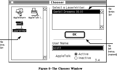 Figure 8–The Chooser Window
As described elsewhere in this chapter, the Chooser can also prompt the user for which AppleTalk network zone to communicate with. See Figure 9.
Figure 8–The Chooser Window
As described elsewhere in this chapter, the Chooser can also prompt the user for which AppleTalk network zone to communicate with. See Figure 9.
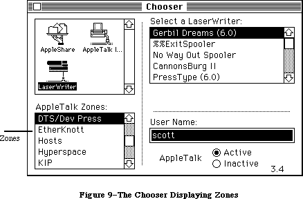 Figure 9–The Chooser Displaying Zones
»Buttons
A device package can choose to have 0, 1, or 2 buttons, as determined by bits 27 and 26 in the flag field of the device ID. The two buttons are not the same. The button set by bit 27 is called the Left Button, and the button set by bit 26 the Right Button, because these are their default positions.
The Left Button has a double border, and if it is highlighted (the title string is dark, not gray), then a Return, Enter, or double click are equivalent to clicking the button. The Left Button is highlighted only when one or more devices are selected in the device list. The Right Button has a single border, never dims its title, and can be activated only by clicking it.
Buttons can be positioned by having a resource type 'nrct' with an ID of –4096 in the device file. The first word of the resource is the number of rectangles in the list, in this case two; the rest of the resource contains the rectangle definitions. The first rectangle is the Left Button, the second is the Right Button.
Each rectangle definition is eight bytes long and contains the rectangle coordinates in the order [top, left, bottom, right] order. The default values are [112, 206, 132, 266] for the Left Button, and [112, 296, 132, 356] for the Right Button. Substituting 'nrct' values of [112, 251, 132, 311], for example, would center a single button.
There’s an additional button-related change: in the ButtonMsg parameter, the low order byte of the P2 parameter has a value of 1 or 2 depending on whether the Left Button or Right Button was clicked. The high order word of P2 now contains modifier bits from the event.
»List Definition Procedure
The Chooser uses the List Manager to produce and display the standard device list. The programmer can now supply a list definition procedure, which could, for example, include pictures or icons. The application should provide an
'LDEF' resource with an ID of –4096.
Also, with Chooser 3.0 and above the device may use the refCon field of the device list for its own purposes. Remember that the list will be disposed of whenever the user changes device types or changes the current zone.
Before the list is disposed of, the device package will be called with the terminate message.
See the List Manager chapter for the mechanics of list construction and the list record data structure.
»Page Setup
The Chooser normally issues a warning message whenever a different printer type is selected:
Be sure to choose Page Setup and confirm the settings so that
the application can format documents correctly for the <printer>.
Since some applications handle the page resetup correctly on their own, the Chooser now offers a way for applications to bypass the message.
FUNCTION SetChooserAlert (f:BOOLEAN) : BOOLEAN;
If f is true, the Chooser will put up the page setup alert; if f is false it won’t. SetChooserAlert returns the original alert state. The application should restore the original alert state when it exits.
Assembly-language note: If the psAlert bit of the low-memory global
HiliteMode is 0 then no page setup alert will be
generated. Applications that set or clear this
bit must be sure not to affect any other bits in
the byte and to restore the bit as they leave.
HiliteMode equ $938
psAlert equ 6
bclr #psAlert,HiliteMode
bset #psAlert,HiliteMode
»Device Package Function
When the device package is called, the device file will be the current resource file, the Chooser’s window will be the current grafPort, and the System Folder of the current startup disk will be the default volume. The device package must preserve all of these.
_______________________________________________________________________________
»THE STARTUP PROCESS
_______________________________________________________________________________
Note: The extensions to the Device Manager described in the following
sections were originally documented in Inside Macintosh, Volume V.
As such, this information refers to the Macintosh SE and Macintosh II
ROMs and System file version 4.1 and later.
The Macintosh II ROM searches for the startup device using an algorithm described in the Start Manager chapter. It will attempt to start from a NuBus card only when certain values are set in its parameter RAM. These values can be accessed by using Start Manager routines.
When the Macintosh starts up from a card in a NuBus slot, it uses startup code found in an sResource in the configuration ROM on the card. Otherwise, the normal Macintosh startup process occurs. Configuration ROMs and sResources are described in the Slot Manager chapter and in the book “Designing Cards and Drivers for Macintosh II and Macintosh SE.”
If parameter RAM specifies a valid sResource ID and slot, and if that sResource has an sBootRecord, it is used for startup. The ROM loads the slot startup code into memory and calls its entry point to execute it. For non-Macintosh operating systems that take over the machine, this code is either the operating system itself or a startup program. For instance, a traditional UNIX® startup process would bring in the secondary startup program, which prompts for a device name or filename to execute. The ROM would never receive control again.
The sBootRecord code is first called early in the ROM-based startup sequence, before any access to the internal drive. It is passed an seBlock pointed to by register A0. If a non-Macintosh operating system is being installed, the sBootRecord can pass control to it. In this case, control never returns to the normal start sequence in the Macintosh ROM.
When the Macintosh operating system is started up, the sBootRecord is called twice. The first time, when the value of seBootState is 0, the startup code tries to load and open at least one driver for the card-based device and install it in the disk drive queue. It returns the refnum of the driver. That driver becomes the initial one used to install the Macintosh operating system. During the second call to the sBootRecord (when the value of seBootState is 1), which happens after system patches have been installed but before 'INIT' resources have been executed, the sBootRec must open any remaining drivers for devices on the card.
The sBootRecord can use the HOpen call to open the driver and install it into the unit table. The HOpen call will either fetch the driver from the sDriver directory, or call the sLoadDriver record if one exists. In any case, the driver’s open code must install the driver into the drive queue. This process is discussed in more detail in the Card Firmware chapter of the book “Designing Cards and Drivers for Macintosh II and Macintosh SE.”
_______________________________________________________________________________
»Automatic Driver Installation
During the startup process the system installs the default video and startup drivers, as described in the Start Manager chapter. Immediately prior to installing the 'INIT' resources, the system searches the NuBus slots looking for other device drivers to install. The sRsrcDir data structure in each
card’s configuration ROM describes all devices on that card. For each device there is a sRsrcList structure which contains the resource name (sRsrcName) and the offset to a table of drivers. These structures are described in the Slot Manager chapter.
For each sResource, the search for drivers during startup takes place in the following steps:
1. The operating system looks for an sRsrc_Flags field in the sResource list.
2. If no sRsrc_Flags field exists, or if an sRsrc_Flags field exists and
the field’s fOpenAtStart bit is set to 1, the operating system searches
for a driver, as described below in steps 3 and 4. If the value of
fOpenAtStart is 0, the operating system does not search for a driver;
it goes on to the next sResource.
3. The system searches the sResource list for a driver load record
(sRsrc_LoadRec)— a routine designed to copy a driver into the Macintosh
system heap. If such a routine exists, the system copies it from the
card’s ROM to the heap and executes it. The system passes this routine
a pointer in A0 to an seBlock; on exit, the routine must return a handle
in the seResult field of the same seBlock to the driver it has loaded.
If the value of the seStatus field is 0, the system then installs the
new driver.
4. If there is no driver load record, the system searches the sResource
list for a driver directory entry (sRsrc_DrvrDir). If there is such
an entry and the directory contains a driver of the type sMacOS68000
or sMacOS68020, the system reads the driver from the card’s ROM and
installs it in the Macintosh system heap.
To install a driver, the Macintosh II ROM first loads it into the system heap and locks it if the dNeedsLock bit in the driver flags (drvrFlags) word is set. It then installs the driver with a DrvrInstall system call and initializes it with an Open call. If the driver returns an error from the Open call, it is marked closed, the refNum field is cleared in the ioParameter block, and the driver is unlocked. Note that this procedure guarantees that driver initialization code will be executed before the system starts executing applications.
The video driver used at the beginning of system startup (the one that makes the “happy Macintosh” appear) must be taken from a video card’s configuration ROM because the System file is not yet accessible. If a system contains multiple video cards, the one used first is determined by parameter RAM or, by default, by selecting the lowest slot number. To override this initial driver, the user must install an 'INIT' 31 resource that explicitly closes the driver from the configuration ROM and loads a new driver from a file.
The unit table data structure has been extended from 48 devices to 64 to accommodate installing slot devices. If more than 64 entries are needed, the table automatically expands up to a maximum of 128 entries.
When a driver serves a device that is plugged into a NuBus slot, it needs to know the slot number, the sResource ID number and the ExtDevID number. These numbers are discussed in the Slot Manager chapter. The Slot Manager provides values for five new entries on the end of the Device Control Entry (DCE) data structure for each sResource. These new entries are
• a byte containing the slot number (dCtlSlot)
• a byte containing the RsrcDir ID number for the sResource (dCtlSlotID)
• a pointer for the driver to use for the device base address (dCtlDevBase)
• a reserved field for future use
• a byte containing the external device ID (dCtlExtDev)
The Device Control Entry now looks like this:
AuxDCE = PACKED RECORD
dCtlDriver: Ptr; {ptr to ROM or handle to RAM driver}
dCtlFlags: INTEGER; {flags}
dCtlQHdr: QHdr; {driver's i/o queue}
dCtlPosition: LONGINT; {byte pos used by read and write calls}
dCtlStorage: Handle; {hndl to RAM drivers private storage}
dCtlRefNum: INTEGER; {driver's reference number}
dCtlCurTicks: LONGINT; {counter for timing system task calls}
dCtlWindow: Ptr; {ptr to driver's window if any}
dCtlDelay: INTEGER; {number of ticks btwn sysTask calls}
dCtlEMask: INTEGER; {desk acessory event mask}
dCtlMenu: INTEGER; {menu ID of menu associated with driver}
dCtlSlot: Byte; {slot}
dCtlSlotId: Byte; {slot ID}
dCtlDevBase: LONGINT; {base address of card for driver}
reserved: LONGINT; {reserved; should be 0}
dCtlExtDev: Byte; {external device ID}
fillByte: Byte; {reserved}
END; {SlotDCE}
AuxDCEPtr = ^AuxDCE;
AuxDCEHandle = ^AuxDCEPtr;
All Device Control Entries are set before the driver’s Open routine is called.
Use of the base address pointer dCtlDevBase in the DCE is optional. On a card with multiple instances of the same device, the driver can use this pointer to distinguish between devices. Because the DCE address is passed to the driver on every call from the Device Manager, the presence of this pointer in the DCE simplifies location of the correct device. This pointer is the address of the base of the card’s slot space plus an optional offset obtained from the MinorBaseOS field of the sResource. This field frees the driver writer from the necessity of locating the hardware for simple slot devices. The system makes no other references to it.
_______________________________________________________________________________
»OPENING SLOT DEVICES
_______________________________________________________________________________
The low-level PBOpen routine has been extended to let you open devices in NuBus slots. A new call has been defined: OpenSlot is the equivalent of PBOpen except that it sets the IMMED bit, which signals an extended parameter block.
FUNCTION OpenSlot(paramBlock: paramBlkPtr; aSync: BOOLEAN) : OsErr;
If the slot sResource serves a single device (for example, a video device), clear all the bits of the ioFlags field and use the following parameter block:
Parameter block
--> 12 ioCompletion pointer
<-- 16 ioResult word
--> 18 ioNamePtr pointer
<-- 22 ioRefNum word
--> 27 ioPermssn byte
--> 28 ioMix pointer
--> 32 ioFlags word
--> 34 ioSlot byte
--> 35 ioId byte
In the extension fields, ioMix is a pointer reserved for use by the driver open routine. The ioSlot parameter contains the slot number of the device being opened, in the range 9..$E; if a built-in device is being opened, ioSlot must be 0. The ioId parameter contains the sResource ID. Slot numbers and sResources are discussed in the Slot Manager.
If the slot sResource serves more than one device (for example, a chain of disk drives), set the fMulti bit in the ioFlags field (clearing all other flags bits to 0) and use the following parameter block:
Parameter block
--> 12 ioCompletion pointer
<-- 16 ioResult word
--> 18 ioNamePtr pointer
<-- 22 ioRefNum word
--> 27 ioPermssn byte
--> 28 ioMix pointer
--> 32 ioFlags word
--> 34 ioSEBlkPtr pointer
Here the new parameter ioSEBlkPtr is a pointer to an external parameter block
(described in the Slot Manager chapter) that is customized for the devices installed in the slot. The pointer value is passed to the driver.
_______________________________________________________________________________
»SLOT DEVICE INTERRUPTS
_______________________________________________________________________________
Slot interrupts enter the system by way of the Macintosh II VIA2 chip, which contains an 8-bit register that has a bit for each slot. This means that there is effectively one interrupt line per card. You can tell almost instantly which card requested the interrupt, but not which device on the card. To locate the interrupt to a device, the Slot Manager provides the polling procedure described below.
The Device Manager maintains an interrupt queue for each slot. The queue elements are ordered by priority and contain pointers to polling routines. Upon receipt of a slot interrupt the Device Manager goes through the slot’s interrupt queue, calling each polling routine, until it gets an indication that the interrupt has been satisfied. If no such indication occurs, a system error dialog is displayed.
The format for a slot interrupt queue element is the following:
SQLink EQU 0 ;link to next element (pointer)
SQType EQU 4 ;queue type ID for validity (word)
SQPrio EQU 6 ;priority (low byte of word)
SQAddr EQU 8 ;interrupt service routine (pointer)
SQParm EQU 12 ;optional A1 parameter (long)
The SQLink field points to the next queue entry; it is maintained by the system. The SQType field identifies the structure as an element of a slot interrupt queue. It should be set to SIQType. The SQPrio field is an unsigned byte that determines the order in which slots are polled and routines are called. Higher value routines are called sooner. Priority values 200–255 are reserved for Apple devices. The SQAddr field points to the interrupt polling routine.
X-Ref: Technical Note #221
X-Ref: Technical Note #257
The SQParm field is a value which is loaded into A1 before calling an interrupt service routine. This could be a handle to the driver’s DCE, for example.
_______________________________________________________________________________
»NEW ROUTINES
_______________________________________________________________________________
The Device Manager provides two new routines to implement the interrupt queue process just described: SIntInstall and SIntRemove. They are described below.
FUNCTION SIntInstall(sIntQElemPtr: SQElemPtr; theSlot: INTEGER) : OsErr;
Trap macro _SIntInstall
On entry D0: slot number (word)
A0: address of slot queue element
On exit D0: error code
SIntInstall adds a new element (pointed to by sIntQElemPtr) to the interrupt queue for the slot whose number is given in theSlot. As explained in the Slot Manager chapter, slots are numbered from 9 to $E.
Assembly-language note: From assembly language, this routine has the
following calling sequence (assuming A0 points
to a slot queue element):
LEA PollRoutine,A1 ;get routine address
MOVE.L A1,SQAddr(A0) ;set address
MOVE.W Prio,SQPrio(A0) ;set priority
MOVE.L A1Parm,SQParm(A0) ;save A1 parameter
MOVE.W Slot,D0 ;set slot number
_SIntInstall ;do installation
This code causes the routine at label PollRoutine to
be called as a result of an interrupt from the
specified slot (9..$E). The Device Manager will
poll the slot which has the highest priority first if
two or more slots request an interrupt simultaneously.
FUNCTION SIntRemove(sIntQElemPtr: SQElemPtr; theSlot: INTEGER) : OsErr;
Trap macro _SIntRemove
On entry D0: slot number (word)
A0: address of slot queue element
On exit D0: error code
SIntRemove removes an element (pointed to by sIntQElemPtr) from the interrupt queue for the slot whose number is given in theSlot. As explained in the Slot Manager chapter, slots are numbered from 9 to $E.
Assembly-language note: From assembly language, this routine has the
following calling sequence (assuming A0 points
to a slot queue element):
LEA MySQEl,A0 ;pointer to queue element
_SIntRemove ;remove it
This routine lets you remove an interrupt handler
from the system without causing a crash.
Your driver polling routine will be called with the following assembly-language code:
MOVE.L A1Parm,A1 ;load A1 Parameter
JSR PollRoutine ;call polling routine
Your polling routine should preserve the contents of all registers except A1 and D0. It should return to the Device Manager with an RTS instruction. D0 should be set to zero to indicate that the polling routine did not service the interrupt, or nonzero to indicate the interrupt has been serviced. The polling routine should not set the processor priority below 2, and should return with the processor priority equal to 2. The Device Manager resets the VIA2 int flag and executes an RTE to the interrrupted task when a polling routine indicates that the interrupt is satisfied; otherwise, it calls the next lower-priority polling routine for that slot. If none exists, a system error results.
_______________________________________________________________________________
»SUMMARY OF THE DEVICE MANAGER
_______________________________________________________________________________
Constants
CONST
{ Values for requesting read/write access }
fsCurPerm = 0; {whatever is currently allowed}
fsRdPerm = 1; {request to read only}
fsWrPerm = 2; {request to write only}
fsRdWrPerm = 3; {request to read and write}
{ Positioning modes }
fsAtMark = 0; {at current position}
fsFromStart = 1; {offset relative to beginning of medium}
fsFromMark = 3; {offset relative to current position}
rdVerify = 64; {add to above for read-verify}
[Volume IV additions]
{Chooser message values}
newSelMsg = 12; {new user selections have been made}
fillListMsg = 13; {fill the list with choices to be made}
getSelMsg = 14; {mark one or more choices as selected}
selectMsg = 15; {a choice has actually been made}
deselectMsg = 16; {a choice has been cancelled}
terminateMsg = 17; {lets device package clean up}
buttonMsg = 19; {tells driver a button has been selected}
{caller values}
chooserID = 1; {caller value for the Chooser}
_______________________________________________________________________________
Data Types
TYPE
ParamBlkType = (ioParam,fileParam,volumeParam,cntrlParam);
ParamBlockRec = RECORD
qLink: QElemPtr; {next queue entry}
qType: INTEGER; {queue type}
ioTrap: INTEGER; {routine trap}
ioCmdAddr: Ptr; {routine address}
ioCompletion: ProcPtr; {completion routine}
ioResult: OSErr; {result code}
ioNamePtr: StringPtr; {driver name}
ioVRefNum: INTEGER; {volume reference or }
{ drive number}
CASE ParamBlkType OF
ioParam:
(ioRefNum: INTEGER; {driver reference number}
ioVersNum: SignedByte; {not used}
ioPermssn: SignedByte; {read/write permission}
ioMisc: Ptr; {not used}
ioBuffer: Ptr; {pointer to data buffer}
ioReqCount: LONGINT; {requested number of bytes}
ioActCount: LONGINT; {actual number of bytes}
ioPosMode: INTEGER; {positioning mode}
ioPosOffset: LONGINT); {positioning offset}
fileParam:
. . . {used by the File Manager}
volumeParam:
. . . {used by the File Manager}
cntrlParam:
(ioCRefNum: INTEGER; {driver reference number}
csCode: INTEGER; {type of Control or Status call}
csParam: ARRAY[0..10] OF INTEGER); {control or status }
{ information}
END;
DCtlHandle = ^DCtlPtr;
DCtlPtr = ^DCtlEntry;
DCtlEntry = RECORD
dCtlDriver: Ptr; {pointer to ROM driver or }
{ handle to RAM driver}
dCtlFlags: INTEGER; {flags}
dCtlQHdr: QHdr; {driver I/O queue header}
dCtlPosition: LONGINT; {byte position used by Read }
{ and Write calls}
dCtlStorage: Handle; {handle to RAM driver's }
{ private storage}
dCtlRefNum: INTEGER; {driver reference number}
dCtlCurTicks: LONGINT; {used internally}
dCtlWindow: WindowPtr; {pointer to driver's window}
dCtlDelay: INTEGER; {number of ticks between }
{ periodic actions}
dCtlEMask: INTEGER; {desk accessory event mask}
dCtlMenu: INTEGER {menu ID of menu associated
{ with driver}
END;
_______________________________________________________________________________
High-Level Routines [Not in ROM]
FUNCTION OpenDriver (name: Str255; VAR refNum: INTEGER) : OSErr;
FUNCTION CloseDriver (refNum: INTEGER) : OSErr;
FUNCTION FSRead (refNum: INTEGER; VAR count: LONGINT;
buffPtr: Ptr) : OSErr;
FUNCTION FSWrite (refNum: INTEGER; VAR count: LONGINT;
buffPtr: Ptr) : OSErr;
FUNCTION Control (refNum: INTEGER; csCode: INTEGER;
csParamPtr: Ptr) : OSErr;
FUNCTION Status (refNum: INTEGER; csCode: INTEGER;
csParamPtr: Ptr) : OSErr;
FUNCTION KillIO (refNum: INTEGER) : OSErr;
[Volume IV addition]
FUNCTION Device (message,caller: INTEGER; objName,zoneName: StringPtr;
p1,p2: LONGINT) : OSErr;
[Volume V additions]
FUNCTION OpenSlot (paramBlock: paramBlkPtr; aSync: BOOLEAN) : OsErr;
FUNCTION SIntInstall (sIntQElemPtr: SQElemPtr; theSlot: INTEGER ) : OsErr;
FUNCTION SIntRemove (sIntQElemPtr: SQElemPtr; theSlot: INTEGER) : OsErr;
_______________________________________________________________________________
Low-Level Routines
FUNCTION PBOpen (paramBlock: ParmBlkPtr; async: BOOLEAN) : OSErr;
--> 12 ioCompletion pointer
<-- 16 ioResult word
--> 18 ioNamePtr pointer
<-- 24 ioRefNum word
--> 27 ioPermssn byte
FUNCTION PBClose (paramBlock: ParmBlkPtr; async: BOOLEAN) : OSErr;
--> 12 ioCompletion pointer
<-- 16 ioResult word
--> 24 ioRefNum word
FUNCTION PBRead (paramBlock: ParmBlkPtr; async: BOOLEAN) : OSErr;
--> 12 ioCompletion pointer
<-- 16 ioResult word
--> 22 ioVRefNum word
--> 24 ioRefNum word
--> 32 ioBuffer pointer
--> 36 ioReqCount long word
<-- 40 ioActCount long word
--> 44 ioPosMode word
<-> 46 ioPosOffset long word
FUNCTION PBWrite (paramBlock: ParmBlkPtr; async: BOOLEAN) : OSErr;
--> 12 ioCompletion pointer
<-- 16 ioResult word
--> 22 ioVRefNum word
--> 24 ioRefNum word
--> 32 ioBuffer pointer
--> 36 ioReqCount long word
<-- 40 ioActCount long word
--> 44 ioPosMode word
<-> 46 ioPosOffset long word
FUNCTION PBControl (paramBlock: ParmBlkPtr; async: BOOLEAN) : OSErr;
--> 12 ioCompletion pointer
<-- 16 ioResult word
--> 22 ioVRefNum word
--> 24 ioRefNum word
--> 26 csCode word
--> 28 csParam record
FUNCTION PBStatus (paramBlock: ParmBlkPtr; async: BOOLEAN) : OSErr;
--> 12 ioCompletion pointer
<-- 16 ioResult word
--> 22 ioVRefNum word
--> 24 ioRefNum word
--> 26 csCode word
<-- 28 csParam record
FUNCTION PBKillIO (paramBlock: ParmBlkPtr; async: BOOLEAN) : OSErr;
--> 12 ioCompletion pointer
<-- 16 ioResult word
--> 24 ioRefNum word
_______________________________________________________________________________
Accessing a Driver’s Device Control Entry
FUNCTION GetDCtlEntry (refNum: INTEGER) : DCtlHandle; [Not in ROM]
_______________________________________________________________________________
Result Codes
Name Value Meaning
abortErr –27 I/O request aborted by KillIO
badUnitErr –21 Driver reference number doesn’t match unit table
controlErr –17 Driver can’t respond to this Control call
dInstErr –26 Couldn’t find driver in resource file
dRemovErr –25 Attempt to remove an open driver
noErr 0 No error
notOpenErr –28 Driver isn’t open
openErr –23 Requested read/write permission doesn’t match
driver’s open permission
readErr –19 Driver can’t respond to Read calls
statusErr –18 Driver can’t respond to this Status call
unitEmptyErr –22 Driver reference number specifies NIL handle in unit table
writErr –20 Driver can’t respond to Write calls
_______________________________________________________________________________
Assembly-Language Information
Constants
; Flags in trap words
asnycTrpBit .EQU 10 ;set for an asynchronous call
noQueueBit .EQU 9 ;set for immediate execution
; Values for requesting read/write access
fsCurPerm .EQU 0 ;whatever is currently allowed
fsRdPerm .EQU 1 ;request to read only
fsWrPerm .EQU 2 ;request to write only
fsRdWrPerm .EQU 3 ;request to read and write
; Positioning modes
fsAtMark .EQU 0 ;at current position
fsFromStart .EQU 1 ;offset relative to beginning of medium
fsFromMark .EQU 3 ;offset relative to current position
rdVerify .EQU 64 ;add to above for read-verify
; Driver flags
dReadEnable .EQU 0 ;set if driver can respond to Read calls
dWritEnable .EQU 1 ;set if driver can respond to Write calls
dCtlEnable .EQU 2 ;set if driver can respond to Control calls
dStatEnable .EQU 3 ;set if driver can respond to Status calls
dNeedGoodBye .EQU 4 ;set if driver needs to be called before the
; application heap is reinitialized
dNeedTime .EQU 5 ;set if driver needs time for performing a
; periodic action
dNeedLock .EQU 6 ;set if driver will be locked in memory as
; soon as it's opened (always set for ROM drivers)
; Device control entry flags
dOpened .EQU 5 ;set if driver is open
dRAMBased .EQU 6 ;set if driver is RAM-based
drvrActive .EQU 7 ;set if driver is currently executing
; csCode values for driver control routine
accRun .EQU 65 ;take the periodic action, if any, for this driver
goodBye .EQU –1 ;heap will be reinitialized, clean up if necessary
killCode .EQU 1 ;handle the KillIO call
; Low-order byte of Device Manager traps
aRdCmd .EQU 2 ;Read call (trap $A002)
aWrCmd .EQU 3 ;Write call (trap $A003)
; Offsets from SCC base addresses
aData .EQU 6 ;channel A data in or out
aCtl .EQU 2 ;channel A control
bData .EQU 4 ;channel B data in or out
bCtl .EQU 0 ;channel B control
[Volume IV additions]
; Chooser message values
newSel .EQU 12 ;new user selections have been made
fillList .EQU 13 ;fill the list with choices to be made
getSel .EQU 14 ;mark one or more choices as selected
select .EQU 15 ;a choice has actually been made
deselect .EQU 16 ;a choice has been cancelled
terminate .EQU 17 ;lets device package clean up
button .EQU 19 ;tells driver a button has been selected
; Caller values
chooserID .EQU 1 ;caller value for the Chooser
[Volume V additions]
; Slot Queue Element
SQLink EQU 0 ;link to next element (pointer)
SQType EQU 4 ;queue type ID for validity (word)
SQPrio EQU 6 ;priority (low byte of word)
SQAddr EQU 8 ;interrupt service routine (pointer)
SQParm EQU 12 ;optional A1 parameter (long)
SIQType EQU 6 ;slot interrupt queue element type
Standard Parameter Block Data Structure
qLink Pointer to next queue entry
qType Queue type (word)
ioTrap Routine trap (word)
ioCmdAddr Routine address
ioCompletion Address of completion routine
ioResult Result code (word)
ioVNPtr Pointer to driver name (preceded by length byte)
ioVRefNum Volume reference number (word)
ioDrvNum Drive number (word)
Control and Status Parameter Block Data Structure
ioRefNum Driver reference number (word)
csCode Type of Control or Status call (word)
csParam Parameters for Control or Status call (22 bytes)
I/O Parameter Block Data Structure
ioRefNum Driver reference number (word)
ioPermssn Open permission (byte)
ioBuffer Pointer to data buffer
ioReqCount Requested number of bytes (long)
ioActCount Actual number of bytes (long)
ioPosMode Positioning mode (word)
ioPosOffset Positioning offset (long)
Device Driver Data Structure
drvrFlags Flags (word)
drvrDelay Number of ticks between periodic actions (word)
drvrEMask Desk accessory event mask (word)
drvrMenu Menu ID of menu associated with driver (word)
drvrOpen Offset to open routine (word)
drvrPrime Offset to prime routine (word)
drvrCtl Offset to control routine (word)
drvrStatus Offset to status routine (word)
drvrClose Offset to close routine (word)
drvrName Driver name (preceded by length byte)
Device Control Entry Data Structure
dCtlDriver Pointer to ROM driver or handle to RAM driver
dCtlFlags Flags (word)
dCtlQueue Queue flags: low-order byte is driver’s version number (word)
dCtlQHead Pointer to first entry in driver’s I/O queue
dCtlQTail Pointer to last entry in driver’s I/O queue
dCtlPosition Byte position used by Read and Write calls (long)
dCtlStorage Handle to RAM driver’s private storage
dCtlRefNum Driver’s reference number (word)
dCtlWindow Pointer to driver’s window
dCtlDelay Number of ticks between periodic actions (word)
dCtlEMask Desk accessory event mask (word)
dCtlMenu Menu ID of menu associated with driver (word)
Structure of Primary Interrupt Vector Table
autoInt1 Vector to level-1 interrupt handler
autoInt2 Vector to level-2 interrupt handler
autoInt3 Vector to level-3 interrupt handler
autoInt4 Vector to level-4 interrupt handler
autoInt5 Vector to level-5 interrupt handler
autoInt6 Vector to level-6 interrupt handler
autoInt7 Vector to level-7 interrupt handler
[Volume IV additions]
Device Package Data Structure
Byte Value
0 BRA.S to offset $10
2 Device ID (word)
4 'PACK' (long word)
8 $F000 (–4096)
A Version (word)
C Flags (long word)
10 Start of driver code
[Volume V additions]
Device Control Entry Data Structure
dCtlDriver Pointer to ROM driver or handle to RAM driver
dCtlFlags Flags (word)
dCtlQueue Queue flags: low-order byte is driver’s version number (word)
dCtlQHead Pointer to first entry in driver’s I/O queue
dCtlQTail Pointer to last entry in driver’s I/O queue
dCtlPosition Byte position used by Read and Write calls (long)
dCtlStorage Handle to RAM driver’s private storage
dCtlRefNum Driver’s reference number (word)
dCtlWindow Pointer to driver’s window
dCtlDelay Number of ticks between periodic actions (word)
dCtlEMask Desk accessory event mask (word)
dCtlMenu Menu ID of menu associated with driver (word)
dCtlSlot Slot number (byte)
dCtlSlotID Resource directory ID number for sResource (byte)
dCtlDevBase Device base address (pointer)
reserved Longint reserved for future use (should be 0)
dCtlExtDev External device ID (byte)
OpenSlot Parameter Blocks
If fMulti bit in ioFlags = 0:
--> 12 ioCompletion pointer
<-- 16 ioResult word
--> 18 ioNamePtr pointer
<-- 22 ioRefNum word
--> 27 ioPermssn byte
--> 28 ioMix pointer
--> 32 ioFlags word
--> 34 ioSlot byte
--> 35 ioId byte
If fMulti bit in ioFlags = 1:
--> 12 ioCompletion pointer
<-- 16 ioResult word
--> 18 ioNamePtr pointer
<-- 22 ioRefNum word
--> 26 ioPermssn byte
--> 28 ioMix pointer
--> 32 ioFlags word
--> 34 ioSEBlkPtr pointer
Macro Names
Pascal name Macro name
PBRead _Read
PBWrite _Write
PBControl _Control
PBStatus _Status
PBKillIO _KillIO
Volume V additions
sIntInstall _sIntInstall
sIntRemove _sIntRemove
_______________________________________________________________________________
Routines for Writing Drivers
Routine Jump vector On entry On exit
Fetch JFetch A1: ptr to device D0: character fetched; bit 15=1
control entry if last character in buffer
Stash JStash A1: ptr to device D0: bit 15=1 if last character
control entry requested
D0: character to stash
IODone JIODone A1: ptr to device
control entry
D0: result code (word)
Variables
UTableBase Base address of unit table
JFetch Jump vector for Fetch function
JStash Jump vector for Stash function
JIODone Jump vector for IODone function
Lvl1DT Level-1 secondary interrupt vector table (32 bytes)
Lvl2DT Level-2 secondary interrupt vector table (32 bytes)
VIA VIA base address
ExtStsDT External/status interrupt vector table (16 bytes)
SCCWr SCC write base address
SCCRd SCC read base address
Further Reference:
_______________________________________________________________________________
Resource Manager
Desk Manager
File Manager
OS Utilities
Start Manager
Slot Manager
List Manager Package
Disk Driver
Serial Drivers
Technical Note #36, Drive Queue Elements
Technical Note #56, Break/CTS Device Driver Event Structure
Technical Note #71, Finding Drivers in the Unit Table
Technical Note #108, AddDrive, DrvrInstall and DrvrRemove
Technical Note #187, Don’t Look at ioPosOffset
Technical Note #197, Chooser Enhancements
Technical Note #208, Setting and Restoring A5
Technical Note #221, NuBus Interrupt Latency
Technical Note #250, AppleTalk Phase 2 on the Macintosh
Technical Note #257, Slot Interrupt Prio-Technics
Q & A Stack
“Macintosh Family Hardware Reference”
“Designing Cards and Drivers for the Macintosh II and Macintosh SE”
Figure 9–The Chooser Displaying Zones
»Buttons
A device package can choose to have 0, 1, or 2 buttons, as determined by bits 27 and 26 in the flag field of the device ID. The two buttons are not the same. The button set by bit 27 is called the Left Button, and the button set by bit 26 the Right Button, because these are their default positions.
The Left Button has a double border, and if it is highlighted (the title string is dark, not gray), then a Return, Enter, or double click are equivalent to clicking the button. The Left Button is highlighted only when one or more devices are selected in the device list. The Right Button has a single border, never dims its title, and can be activated only by clicking it.
Buttons can be positioned by having a resource type 'nrct' with an ID of –4096 in the device file. The first word of the resource is the number of rectangles in the list, in this case two; the rest of the resource contains the rectangle definitions. The first rectangle is the Left Button, the second is the Right Button.
Each rectangle definition is eight bytes long and contains the rectangle coordinates in the order [top, left, bottom, right] order. The default values are [112, 206, 132, 266] for the Left Button, and [112, 296, 132, 356] for the Right Button. Substituting 'nrct' values of [112, 251, 132, 311], for example, would center a single button.
There’s an additional button-related change: in the ButtonMsg parameter, the low order byte of the P2 parameter has a value of 1 or 2 depending on whether the Left Button or Right Button was clicked. The high order word of P2 now contains modifier bits from the event.
»List Definition Procedure
The Chooser uses the List Manager to produce and display the standard device list. The programmer can now supply a list definition procedure, which could, for example, include pictures or icons. The application should provide an
'LDEF' resource with an ID of –4096.
Also, with Chooser 3.0 and above the device may use the refCon field of the device list for its own purposes. Remember that the list will be disposed of whenever the user changes device types or changes the current zone.
Before the list is disposed of, the device package will be called with the terminate message.
See the List Manager chapter for the mechanics of list construction and the list record data structure.
»Page Setup
The Chooser normally issues a warning message whenever a different printer type is selected:
Be sure to choose Page Setup and confirm the settings so that
the application can format documents correctly for the <printer>.
Since some applications handle the page resetup correctly on their own, the Chooser now offers a way for applications to bypass the message.
FUNCTION SetChooserAlert (f:BOOLEAN) : BOOLEAN;
If f is true, the Chooser will put up the page setup alert; if f is false it won’t. SetChooserAlert returns the original alert state. The application should restore the original alert state when it exits.
Assembly-language note: If the psAlert bit of the low-memory global
HiliteMode is 0 then no page setup alert will be
generated. Applications that set or clear this
bit must be sure not to affect any other bits in
the byte and to restore the bit as they leave.
HiliteMode equ $938
psAlert equ 6
bclr #psAlert,HiliteMode
bset #psAlert,HiliteMode
»Device Package Function
When the device package is called, the device file will be the current resource file, the Chooser’s window will be the current grafPort, and the System Folder of the current startup disk will be the default volume. The device package must preserve all of these.
_______________________________________________________________________________
»THE STARTUP PROCESS
_______________________________________________________________________________
Note: The extensions to the Device Manager described in the following
sections were originally documented in Inside Macintosh, Volume V.
As such, this information refers to the Macintosh SE and Macintosh II
ROMs and System file version 4.1 and later.
The Macintosh II ROM searches for the startup device using an algorithm described in the Start Manager chapter. It will attempt to start from a NuBus card only when certain values are set in its parameter RAM. These values can be accessed by using Start Manager routines.
When the Macintosh starts up from a card in a NuBus slot, it uses startup code found in an sResource in the configuration ROM on the card. Otherwise, the normal Macintosh startup process occurs. Configuration ROMs and sResources are described in the Slot Manager chapter and in the book “Designing Cards and Drivers for Macintosh II and Macintosh SE.”
If parameter RAM specifies a valid sResource ID and slot, and if that sResource has an sBootRecord, it is used for startup. The ROM loads the slot startup code into memory and calls its entry point to execute it. For non-Macintosh operating systems that take over the machine, this code is either the operating system itself or a startup program. For instance, a traditional UNIX® startup process would bring in the secondary startup program, which prompts for a device name or filename to execute. The ROM would never receive control again.
The sBootRecord code is first called early in the ROM-based startup sequence, before any access to the internal drive. It is passed an seBlock pointed to by register A0. If a non-Macintosh operating system is being installed, the sBootRecord can pass control to it. In this case, control never returns to the normal start sequence in the Macintosh ROM.
When the Macintosh operating system is started up, the sBootRecord is called twice. The first time, when the value of seBootState is 0, the startup code tries to load and open at least one driver for the card-based device and install it in the disk drive queue. It returns the refnum of the driver. That driver becomes the initial one used to install the Macintosh operating system. During the second call to the sBootRecord (when the value of seBootState is 1), which happens after system patches have been installed but before 'INIT' resources have been executed, the sBootRec must open any remaining drivers for devices on the card.
The sBootRecord can use the HOpen call to open the driver and install it into the unit table. The HOpen call will either fetch the driver from the sDriver directory, or call the sLoadDriver record if one exists. In any case, the driver’s open code must install the driver into the drive queue. This process is discussed in more detail in the Card Firmware chapter of the book “Designing Cards and Drivers for Macintosh II and Macintosh SE.”
_______________________________________________________________________________
»Automatic Driver Installation
During the startup process the system installs the default video and startup drivers, as described in the Start Manager chapter. Immediately prior to installing the 'INIT' resources, the system searches the NuBus slots looking for other device drivers to install. The sRsrcDir data structure in each
card’s configuration ROM describes all devices on that card. For each device there is a sRsrcList structure which contains the resource name (sRsrcName) and the offset to a table of drivers. These structures are described in the Slot Manager chapter.
For each sResource, the search for drivers during startup takes place in the following steps:
1. The operating system looks for an sRsrc_Flags field in the sResource list.
2. If no sRsrc_Flags field exists, or if an sRsrc_Flags field exists and
the field’s fOpenAtStart bit is set to 1, the operating system searches
for a driver, as described below in steps 3 and 4. If the value of
fOpenAtStart is 0, the operating system does not search for a driver;
it goes on to the next sResource.
3. The system searches the sResource list for a driver load record
(sRsrc_LoadRec)— a routine designed to copy a driver into the Macintosh
system heap. If such a routine exists, the system copies it from the
card’s ROM to the heap and executes it. The system passes this routine
a pointer in A0 to an seBlock; on exit, the routine must return a handle
in the seResult field of the same seBlock to the driver it has loaded.
If the value of the seStatus field is 0, the system then installs the
new driver.
4. If there is no driver load record, the system searches the sResource
list for a driver directory entry (sRsrc_DrvrDir). If there is such
an entry and the directory contains a driver of the type sMacOS68000
or sMacOS68020, the system reads the driver from the card’s ROM and
installs it in the Macintosh system heap.
To install a driver, the Macintosh II ROM first loads it into the system heap and locks it if the dNeedsLock bit in the driver flags (drvrFlags) word is set. It then installs the driver with a DrvrInstall system call and initializes it with an Open call. If the driver returns an error from the Open call, it is marked closed, the refNum field is cleared in the ioParameter block, and the driver is unlocked. Note that this procedure guarantees that driver initialization code will be executed before the system starts executing applications.
The video driver used at the beginning of system startup (the one that makes the “happy Macintosh” appear) must be taken from a video card’s configuration ROM because the System file is not yet accessible. If a system contains multiple video cards, the one used first is determined by parameter RAM or, by default, by selecting the lowest slot number. To override this initial driver, the user must install an 'INIT' 31 resource that explicitly closes the driver from the configuration ROM and loads a new driver from a file.
The unit table data structure has been extended from 48 devices to 64 to accommodate installing slot devices. If more than 64 entries are needed, the table automatically expands up to a maximum of 128 entries.
When a driver serves a device that is plugged into a NuBus slot, it needs to know the slot number, the sResource ID number and the ExtDevID number. These numbers are discussed in the Slot Manager chapter. The Slot Manager provides values for five new entries on the end of the Device Control Entry (DCE) data structure for each sResource. These new entries are
• a byte containing the slot number (dCtlSlot)
• a byte containing the RsrcDir ID number for the sResource (dCtlSlotID)
• a pointer for the driver to use for the device base address (dCtlDevBase)
• a reserved field for future use
• a byte containing the external device ID (dCtlExtDev)
The Device Control Entry now looks like this:
AuxDCE = PACKED RECORD
dCtlDriver: Ptr; {ptr to ROM or handle to RAM driver}
dCtlFlags: INTEGER; {flags}
dCtlQHdr: QHdr; {driver's i/o queue}
dCtlPosition: LONGINT; {byte pos used by read and write calls}
dCtlStorage: Handle; {hndl to RAM drivers private storage}
dCtlRefNum: INTEGER; {driver's reference number}
dCtlCurTicks: LONGINT; {counter for timing system task calls}
dCtlWindow: Ptr; {ptr to driver's window if any}
dCtlDelay: INTEGER; {number of ticks btwn sysTask calls}
dCtlEMask: INTEGER; {desk acessory event mask}
dCtlMenu: INTEGER; {menu ID of menu associated with driver}
dCtlSlot: Byte; {slot}
dCtlSlotId: Byte; {slot ID}
dCtlDevBase: LONGINT; {base address of card for driver}
reserved: LONGINT; {reserved; should be 0}
dCtlExtDev: Byte; {external device ID}
fillByte: Byte; {reserved}
END; {SlotDCE}
AuxDCEPtr = ^AuxDCE;
AuxDCEHandle = ^AuxDCEPtr;
All Device Control Entries are set before the driver’s Open routine is called.
Use of the base address pointer dCtlDevBase in the DCE is optional. On a card with multiple instances of the same device, the driver can use this pointer to distinguish between devices. Because the DCE address is passed to the driver on every call from the Device Manager, the presence of this pointer in the DCE simplifies location of the correct device. This pointer is the address of the base of the card’s slot space plus an optional offset obtained from the MinorBaseOS field of the sResource. This field frees the driver writer from the necessity of locating the hardware for simple slot devices. The system makes no other references to it.
_______________________________________________________________________________
»OPENING SLOT DEVICES
_______________________________________________________________________________
The low-level PBOpen routine has been extended to let you open devices in NuBus slots. A new call has been defined: OpenSlot is the equivalent of PBOpen except that it sets the IMMED bit, which signals an extended parameter block.
FUNCTION OpenSlot(paramBlock: paramBlkPtr; aSync: BOOLEAN) : OsErr;
If the slot sResource serves a single device (for example, a video device), clear all the bits of the ioFlags field and use the following parameter block:
Parameter block
--> 12 ioCompletion pointer
<-- 16 ioResult word
--> 18 ioNamePtr pointer
<-- 22 ioRefNum word
--> 27 ioPermssn byte
--> 28 ioMix pointer
--> 32 ioFlags word
--> 34 ioSlot byte
--> 35 ioId byte
In the extension fields, ioMix is a pointer reserved for use by the driver open routine. The ioSlot parameter contains the slot number of the device being opened, in the range 9..$E; if a built-in device is being opened, ioSlot must be 0. The ioId parameter contains the sResource ID. Slot numbers and sResources are discussed in the Slot Manager.
If the slot sResource serves more than one device (for example, a chain of disk drives), set the fMulti bit in the ioFlags field (clearing all other flags bits to 0) and use the following parameter block:
Parameter block
--> 12 ioCompletion pointer
<-- 16 ioResult word
--> 18 ioNamePtr pointer
<-- 22 ioRefNum word
--> 27 ioPermssn byte
--> 28 ioMix pointer
--> 32 ioFlags word
--> 34 ioSEBlkPtr pointer
Here the new parameter ioSEBlkPtr is a pointer to an external parameter block
(described in the Slot Manager chapter) that is customized for the devices installed in the slot. The pointer value is passed to the driver.
_______________________________________________________________________________
»SLOT DEVICE INTERRUPTS
_______________________________________________________________________________
Slot interrupts enter the system by way of the Macintosh II VIA2 chip, which contains an 8-bit register that has a bit for each slot. This means that there is effectively one interrupt line per card. You can tell almost instantly which card requested the interrupt, but not which device on the card. To locate the interrupt to a device, the Slot Manager provides the polling procedure described below.
The Device Manager maintains an interrupt queue for each slot. The queue elements are ordered by priority and contain pointers to polling routines. Upon receipt of a slot interrupt the Device Manager goes through the slot’s interrupt queue, calling each polling routine, until it gets an indication that the interrupt has been satisfied. If no such indication occurs, a system error dialog is displayed.
The format for a slot interrupt queue element is the following:
SQLink EQU 0 ;link to next element (pointer)
SQType EQU 4 ;queue type ID for validity (word)
SQPrio EQU 6 ;priority (low byte of word)
SQAddr EQU 8 ;interrupt service routine (pointer)
SQParm EQU 12 ;optional A1 parameter (long)
The SQLink field points to the next queue entry; it is maintained by the system. The SQType field identifies the structure as an element of a slot interrupt queue. It should be set to SIQType. The SQPrio field is an unsigned byte that determines the order in which slots are polled and routines are called. Higher value routines are called sooner. Priority values 200–255 are reserved for Apple devices. The SQAddr field points to the interrupt polling routine.
X-Ref: Technical Note #221
X-Ref: Technical Note #257
The SQParm field is a value which is loaded into A1 before calling an interrupt service routine. This could be a handle to the driver’s DCE, for example.
_______________________________________________________________________________
»NEW ROUTINES
_______________________________________________________________________________
The Device Manager provides two new routines to implement the interrupt queue process just described: SIntInstall and SIntRemove. They are described below.
FUNCTION SIntInstall(sIntQElemPtr: SQElemPtr; theSlot: INTEGER) : OsErr;
Trap macro _SIntInstall
On entry D0: slot number (word)
A0: address of slot queue element
On exit D0: error code
SIntInstall adds a new element (pointed to by sIntQElemPtr) to the interrupt queue for the slot whose number is given in theSlot. As explained in the Slot Manager chapter, slots are numbered from 9 to $E.
Assembly-language note: From assembly language, this routine has the
following calling sequence (assuming A0 points
to a slot queue element):
LEA PollRoutine,A1 ;get routine address
MOVE.L A1,SQAddr(A0) ;set address
MOVE.W Prio,SQPrio(A0) ;set priority
MOVE.L A1Parm,SQParm(A0) ;save A1 parameter
MOVE.W Slot,D0 ;set slot number
_SIntInstall ;do installation
This code causes the routine at label PollRoutine to
be called as a result of an interrupt from the
specified slot (9..$E). The Device Manager will
poll the slot which has the highest priority first if
two or more slots request an interrupt simultaneously.
FUNCTION SIntRemove(sIntQElemPtr: SQElemPtr; theSlot: INTEGER) : OsErr;
Trap macro _SIntRemove
On entry D0: slot number (word)
A0: address of slot queue element
On exit D0: error code
SIntRemove removes an element (pointed to by sIntQElemPtr) from the interrupt queue for the slot whose number is given in theSlot. As explained in the Slot Manager chapter, slots are numbered from 9 to $E.
Assembly-language note: From assembly language, this routine has the
following calling sequence (assuming A0 points
to a slot queue element):
LEA MySQEl,A0 ;pointer to queue element
_SIntRemove ;remove it
This routine lets you remove an interrupt handler
from the system without causing a crash.
Your driver polling routine will be called with the following assembly-language code:
MOVE.L A1Parm,A1 ;load A1 Parameter
JSR PollRoutine ;call polling routine
Your polling routine should preserve the contents of all registers except A1 and D0. It should return to the Device Manager with an RTS instruction. D0 should be set to zero to indicate that the polling routine did not service the interrupt, or nonzero to indicate the interrupt has been serviced. The polling routine should not set the processor priority below 2, and should return with the processor priority equal to 2. The Device Manager resets the VIA2 int flag and executes an RTE to the interrrupted task when a polling routine indicates that the interrupt is satisfied; otherwise, it calls the next lower-priority polling routine for that slot. If none exists, a system error results.
_______________________________________________________________________________
»SUMMARY OF THE DEVICE MANAGER
_______________________________________________________________________________
Constants
CONST
{ Values for requesting read/write access }
fsCurPerm = 0; {whatever is currently allowed}
fsRdPerm = 1; {request to read only}
fsWrPerm = 2; {request to write only}
fsRdWrPerm = 3; {request to read and write}
{ Positioning modes }
fsAtMark = 0; {at current position}
fsFromStart = 1; {offset relative to beginning of medium}
fsFromMark = 3; {offset relative to current position}
rdVerify = 64; {add to above for read-verify}
[Volume IV additions]
{Chooser message values}
newSelMsg = 12; {new user selections have been made}
fillListMsg = 13; {fill the list with choices to be made}
getSelMsg = 14; {mark one or more choices as selected}
selectMsg = 15; {a choice has actually been made}
deselectMsg = 16; {a choice has been cancelled}
terminateMsg = 17; {lets device package clean up}
buttonMsg = 19; {tells driver a button has been selected}
{caller values}
chooserID = 1; {caller value for the Chooser}
_______________________________________________________________________________
Data Types
TYPE
ParamBlkType = (ioParam,fileParam,volumeParam,cntrlParam);
ParamBlockRec = RECORD
qLink: QElemPtr; {next queue entry}
qType: INTEGER; {queue type}
ioTrap: INTEGER; {routine trap}
ioCmdAddr: Ptr; {routine address}
ioCompletion: ProcPtr; {completion routine}
ioResult: OSErr; {result code}
ioNamePtr: StringPtr; {driver name}
ioVRefNum: INTEGER; {volume reference or }
{ drive number}
CASE ParamBlkType OF
ioParam:
(ioRefNum: INTEGER; {driver reference number}
ioVersNum: SignedByte; {not used}
ioPermssn: SignedByte; {read/write permission}
ioMisc: Ptr; {not used}
ioBuffer: Ptr; {pointer to data buffer}
ioReqCount: LONGINT; {requested number of bytes}
ioActCount: LONGINT; {actual number of bytes}
ioPosMode: INTEGER; {positioning mode}
ioPosOffset: LONGINT); {positioning offset}
fileParam:
. . . {used by the File Manager}
volumeParam:
. . . {used by the File Manager}
cntrlParam:
(ioCRefNum: INTEGER; {driver reference number}
csCode: INTEGER; {type of Control or Status call}
csParam: ARRAY[0..10] OF INTEGER); {control or status }
{ information}
END;
DCtlHandle = ^DCtlPtr;
DCtlPtr = ^DCtlEntry;
DCtlEntry = RECORD
dCtlDriver: Ptr; {pointer to ROM driver or }
{ handle to RAM driver}
dCtlFlags: INTEGER; {flags}
dCtlQHdr: QHdr; {driver I/O queue header}
dCtlPosition: LONGINT; {byte position used by Read }
{ and Write calls}
dCtlStorage: Handle; {handle to RAM driver's }
{ private storage}
dCtlRefNum: INTEGER; {driver reference number}
dCtlCurTicks: LONGINT; {used internally}
dCtlWindow: WindowPtr; {pointer to driver's window}
dCtlDelay: INTEGER; {number of ticks between }
{ periodic actions}
dCtlEMask: INTEGER; {desk accessory event mask}
dCtlMenu: INTEGER {menu ID of menu associated
{ with driver}
END;
_______________________________________________________________________________
High-Level Routines [Not in ROM]
FUNCTION OpenDriver (name: Str255; VAR refNum: INTEGER) : OSErr;
FUNCTION CloseDriver (refNum: INTEGER) : OSErr;
FUNCTION FSRead (refNum: INTEGER; VAR count: LONGINT;
buffPtr: Ptr) : OSErr;
FUNCTION FSWrite (refNum: INTEGER; VAR count: LONGINT;
buffPtr: Ptr) : OSErr;
FUNCTION Control (refNum: INTEGER; csCode: INTEGER;
csParamPtr: Ptr) : OSErr;
FUNCTION Status (refNum: INTEGER; csCode: INTEGER;
csParamPtr: Ptr) : OSErr;
FUNCTION KillIO (refNum: INTEGER) : OSErr;
[Volume IV addition]
FUNCTION Device (message,caller: INTEGER; objName,zoneName: StringPtr;
p1,p2: LONGINT) : OSErr;
[Volume V additions]
FUNCTION OpenSlot (paramBlock: paramBlkPtr; aSync: BOOLEAN) : OsErr;
FUNCTION SIntInstall (sIntQElemPtr: SQElemPtr; theSlot: INTEGER ) : OsErr;
FUNCTION SIntRemove (sIntQElemPtr: SQElemPtr; theSlot: INTEGER) : OsErr;
_______________________________________________________________________________
Low-Level Routines
FUNCTION PBOpen (paramBlock: ParmBlkPtr; async: BOOLEAN) : OSErr;
--> 12 ioCompletion pointer
<-- 16 ioResult word
--> 18 ioNamePtr pointer
<-- 24 ioRefNum word
--> 27 ioPermssn byte
FUNCTION PBClose (paramBlock: ParmBlkPtr; async: BOOLEAN) : OSErr;
--> 12 ioCompletion pointer
<-- 16 ioResult word
--> 24 ioRefNum word
FUNCTION PBRead (paramBlock: ParmBlkPtr; async: BOOLEAN) : OSErr;
--> 12 ioCompletion pointer
<-- 16 ioResult word
--> 22 ioVRefNum word
--> 24 ioRefNum word
--> 32 ioBuffer pointer
--> 36 ioReqCount long word
<-- 40 ioActCount long word
--> 44 ioPosMode word
<-> 46 ioPosOffset long word
FUNCTION PBWrite (paramBlock: ParmBlkPtr; async: BOOLEAN) : OSErr;
--> 12 ioCompletion pointer
<-- 16 ioResult word
--> 22 ioVRefNum word
--> 24 ioRefNum word
--> 32 ioBuffer pointer
--> 36 ioReqCount long word
<-- 40 ioActCount long word
--> 44 ioPosMode word
<-> 46 ioPosOffset long word
FUNCTION PBControl (paramBlock: ParmBlkPtr; async: BOOLEAN) : OSErr;
--> 12 ioCompletion pointer
<-- 16 ioResult word
--> 22 ioVRefNum word
--> 24 ioRefNum word
--> 26 csCode word
--> 28 csParam record
FUNCTION PBStatus (paramBlock: ParmBlkPtr; async: BOOLEAN) : OSErr;
--> 12 ioCompletion pointer
<-- 16 ioResult word
--> 22 ioVRefNum word
--> 24 ioRefNum word
--> 26 csCode word
<-- 28 csParam record
FUNCTION PBKillIO (paramBlock: ParmBlkPtr; async: BOOLEAN) : OSErr;
--> 12 ioCompletion pointer
<-- 16 ioResult word
--> 24 ioRefNum word
_______________________________________________________________________________
Accessing a Driver’s Device Control Entry
FUNCTION GetDCtlEntry (refNum: INTEGER) : DCtlHandle; [Not in ROM]
_______________________________________________________________________________
Result Codes
Name Value Meaning
abortErr –27 I/O request aborted by KillIO
badUnitErr –21 Driver reference number doesn’t match unit table
controlErr –17 Driver can’t respond to this Control call
dInstErr –26 Couldn’t find driver in resource file
dRemovErr –25 Attempt to remove an open driver
noErr 0 No error
notOpenErr –28 Driver isn’t open
openErr –23 Requested read/write permission doesn’t match
driver’s open permission
readErr –19 Driver can’t respond to Read calls
statusErr –18 Driver can’t respond to this Status call
unitEmptyErr –22 Driver reference number specifies NIL handle in unit table
writErr –20 Driver can’t respond to Write calls
_______________________________________________________________________________
Assembly-Language Information
Constants
; Flags in trap words
asnycTrpBit .EQU 10 ;set for an asynchronous call
noQueueBit .EQU 9 ;set for immediate execution
; Values for requesting read/write access
fsCurPerm .EQU 0 ;whatever is currently allowed
fsRdPerm .EQU 1 ;request to read only
fsWrPerm .EQU 2 ;request to write only
fsRdWrPerm .EQU 3 ;request to read and write
; Positioning modes
fsAtMark .EQU 0 ;at current position
fsFromStart .EQU 1 ;offset relative to beginning of medium
fsFromMark .EQU 3 ;offset relative to current position
rdVerify .EQU 64 ;add to above for read-verify
; Driver flags
dReadEnable .EQU 0 ;set if driver can respond to Read calls
dWritEnable .EQU 1 ;set if driver can respond to Write calls
dCtlEnable .EQU 2 ;set if driver can respond to Control calls
dStatEnable .EQU 3 ;set if driver can respond to Status calls
dNeedGoodBye .EQU 4 ;set if driver needs to be called before the
; application heap is reinitialized
dNeedTime .EQU 5 ;set if driver needs time for performing a
; periodic action
dNeedLock .EQU 6 ;set if driver will be locked in memory as
; soon as it's opened (always set for ROM drivers)
; Device control entry flags
dOpened .EQU 5 ;set if driver is open
dRAMBased .EQU 6 ;set if driver is RAM-based
drvrActive .EQU 7 ;set if driver is currently executing
; csCode values for driver control routine
accRun .EQU 65 ;take the periodic action, if any, for this driver
goodBye .EQU –1 ;heap will be reinitialized, clean up if necessary
killCode .EQU 1 ;handle the KillIO call
; Low-order byte of Device Manager traps
aRdCmd .EQU 2 ;Read call (trap $A002)
aWrCmd .EQU 3 ;Write call (trap $A003)
; Offsets from SCC base addresses
aData .EQU 6 ;channel A data in or out
aCtl .EQU 2 ;channel A control
bData .EQU 4 ;channel B data in or out
bCtl .EQU 0 ;channel B control
[Volume IV additions]
; Chooser message values
newSel .EQU 12 ;new user selections have been made
fillList .EQU 13 ;fill the list with choices to be made
getSel .EQU 14 ;mark one or more choices as selected
select .EQU 15 ;a choice has actually been made
deselect .EQU 16 ;a choice has been cancelled
terminate .EQU 17 ;lets device package clean up
button .EQU 19 ;tells driver a button has been selected
; Caller values
chooserID .EQU 1 ;caller value for the Chooser
[Volume V additions]
; Slot Queue Element
SQLink EQU 0 ;link to next element (pointer)
SQType EQU 4 ;queue type ID for validity (word)
SQPrio EQU 6 ;priority (low byte of word)
SQAddr EQU 8 ;interrupt service routine (pointer)
SQParm EQU 12 ;optional A1 parameter (long)
SIQType EQU 6 ;slot interrupt queue element type
Standard Parameter Block Data Structure
qLink Pointer to next queue entry
qType Queue type (word)
ioTrap Routine trap (word)
ioCmdAddr Routine address
ioCompletion Address of completion routine
ioResult Result code (word)
ioVNPtr Pointer to driver name (preceded by length byte)
ioVRefNum Volume reference number (word)
ioDrvNum Drive number (word)
Control and Status Parameter Block Data Structure
ioRefNum Driver reference number (word)
csCode Type of Control or Status call (word)
csParam Parameters for Control or Status call (22 bytes)
I/O Parameter Block Data Structure
ioRefNum Driver reference number (word)
ioPermssn Open permission (byte)
ioBuffer Pointer to data buffer
ioReqCount Requested number of bytes (long)
ioActCount Actual number of bytes (long)
ioPosMode Positioning mode (word)
ioPosOffset Positioning offset (long)
Device Driver Data Structure
drvrFlags Flags (word)
drvrDelay Number of ticks between periodic actions (word)
drvrEMask Desk accessory event mask (word)
drvrMenu Menu ID of menu associated with driver (word)
drvrOpen Offset to open routine (word)
drvrPrime Offset to prime routine (word)
drvrCtl Offset to control routine (word)
drvrStatus Offset to status routine (word)
drvrClose Offset to close routine (word)
drvrName Driver name (preceded by length byte)
Device Control Entry Data Structure
dCtlDriver Pointer to ROM driver or handle to RAM driver
dCtlFlags Flags (word)
dCtlQueue Queue flags: low-order byte is driver’s version number (word)
dCtlQHead Pointer to first entry in driver’s I/O queue
dCtlQTail Pointer to last entry in driver’s I/O queue
dCtlPosition Byte position used by Read and Write calls (long)
dCtlStorage Handle to RAM driver’s private storage
dCtlRefNum Driver’s reference number (word)
dCtlWindow Pointer to driver’s window
dCtlDelay Number of ticks between periodic actions (word)
dCtlEMask Desk accessory event mask (word)
dCtlMenu Menu ID of menu associated with driver (word)
Structure of Primary Interrupt Vector Table
autoInt1 Vector to level-1 interrupt handler
autoInt2 Vector to level-2 interrupt handler
autoInt3 Vector to level-3 interrupt handler
autoInt4 Vector to level-4 interrupt handler
autoInt5 Vector to level-5 interrupt handler
autoInt6 Vector to level-6 interrupt handler
autoInt7 Vector to level-7 interrupt handler
[Volume IV additions]
Device Package Data Structure
Byte Value
0 BRA.S to offset $10
2 Device ID (word)
4 'PACK' (long word)
8 $F000 (–4096)
A Version (word)
C Flags (long word)
10 Start of driver code
[Volume V additions]
Device Control Entry Data Structure
dCtlDriver Pointer to ROM driver or handle to RAM driver
dCtlFlags Flags (word)
dCtlQueue Queue flags: low-order byte is driver’s version number (word)
dCtlQHead Pointer to first entry in driver’s I/O queue
dCtlQTail Pointer to last entry in driver’s I/O queue
dCtlPosition Byte position used by Read and Write calls (long)
dCtlStorage Handle to RAM driver’s private storage
dCtlRefNum Driver’s reference number (word)
dCtlWindow Pointer to driver’s window
dCtlDelay Number of ticks between periodic actions (word)
dCtlEMask Desk accessory event mask (word)
dCtlMenu Menu ID of menu associated with driver (word)
dCtlSlot Slot number (byte)
dCtlSlotID Resource directory ID number for sResource (byte)
dCtlDevBase Device base address (pointer)
reserved Longint reserved for future use (should be 0)
dCtlExtDev External device ID (byte)
OpenSlot Parameter Blocks
If fMulti bit in ioFlags = 0:
--> 12 ioCompletion pointer
<-- 16 ioResult word
--> 18 ioNamePtr pointer
<-- 22 ioRefNum word
--> 27 ioPermssn byte
--> 28 ioMix pointer
--> 32 ioFlags word
--> 34 ioSlot byte
--> 35 ioId byte
If fMulti bit in ioFlags = 1:
--> 12 ioCompletion pointer
<-- 16 ioResult word
--> 18 ioNamePtr pointer
<-- 22 ioRefNum word
--> 26 ioPermssn byte
--> 28 ioMix pointer
--> 32 ioFlags word
--> 34 ioSEBlkPtr pointer
Macro Names
Pascal name Macro name
PBRead _Read
PBWrite _Write
PBControl _Control
PBStatus _Status
PBKillIO _KillIO
Volume V additions
sIntInstall _sIntInstall
sIntRemove _sIntRemove
_______________________________________________________________________________
Routines for Writing Drivers
Routine Jump vector On entry On exit
Fetch JFetch A1: ptr to device D0: character fetched; bit 15=1
control entry if last character in buffer
Stash JStash A1: ptr to device D0: bit 15=1 if last character
control entry requested
D0: character to stash
IODone JIODone A1: ptr to device
control entry
D0: result code (word)
Variables
UTableBase Base address of unit table
JFetch Jump vector for Fetch function
JStash Jump vector for Stash function
JIODone Jump vector for IODone function
Lvl1DT Level-1 secondary interrupt vector table (32 bytes)
Lvl2DT Level-2 secondary interrupt vector table (32 bytes)
VIA VIA base address
ExtStsDT External/status interrupt vector table (16 bytes)
SCCWr SCC write base address
SCCRd SCC read base address
Further Reference:
_______________________________________________________________________________
Resource Manager
Desk Manager
File Manager
OS Utilities
Start Manager
Slot Manager
List Manager Package
Disk Driver
Serial Drivers
Technical Note #36, Drive Queue Elements
Technical Note #56, Break/CTS Device Driver Event Structure
Technical Note #71, Finding Drivers in the Unit Table
Technical Note #108, AddDrive, DrvrInstall and DrvrRemove
Technical Note #187, Don’t Look at ioPosOffset
Technical Note #197, Chooser Enhancements
Technical Note #208, Setting and Restoring A5
Technical Note #221, NuBus Interrupt Latency
Technical Note #250, AppleTalk Phase 2 on the Macintosh
Technical Note #257, Slot Interrupt Prio-Technics
Q & A Stack
“Macintosh Family Hardware Reference”
“Designing Cards and Drivers for the Macintosh II and Macintosh SE”
The Dialog Manager
_______________________________________________________________________________
THE DIALOG MANAGER
_______________________________________________________________________________
About This Chapter
About the Dialog Manager
Dialog and Alert Windows
Dialogs, Alerts, and Resources
Color Alert and Dialog Resources
Item Lists in Memory
Item Types
Item Handle or Procedure Pointer
Display Rectangle
Item Numbers
Color Dialog Item Lists
Using Color Dialogs and Alerts
Dialog Records
Dialog Pointers
The DialogRecord Data Type
Alerts
Using the Dialog Manager
Dialog Manager Routines
Initialization
Creating and Disposing of Dialogs
Handling Dialog Events
Invoking Alerts
Manipulating Items in Dialogs and Alerts
Modifying Templates in Memory
Dialog Templates in Memory
Alert Templates in Memory
Formats of Resources for Dialogs and Alerts
Dialog Templates in a Resource File
Alert Templates in a Resource File
Item Lists in a Resource File
Summary of the Dialog Manager
_______________________________________________________________________________
»ABOUT THIS CHAPTER
_______________________________________________________________________________
This chapter describes the Dialog Manager, the part of the Toolbox that allows you to implement dialog boxes and the alert mechanism, two means of communication between the application and the end user.
This chapter also describes the enhancements to the Dialog Manager for the Macintosh II. A new Dialog Manager routine now provides color dialog and item support. The new resource types 'dctb', 'actb', and 'ictb', which are auxiliary data structures to 'DITL', 'ALRT', and 'DLOG', allow color dialog boxes and alert boxes to be stored as resources. If the 'ALRT', 'DLOG', or
'DITL' resources are missing, the Dialog Manager will gracefully return from the Alert, NoteAlert, CautionAlert, StopAlert, and GetNewDialog calls.
You should already be familiar with:
• resources, as discussed in the Resource Manager chapter
• the basic concepts and structures behind QuickDraw, particularly
rectangles, grafPorts, and pictures
• the Toolbox Event Manager, the Window Manager, and the Control Manager
• TextEdit, to understand editing text in dialog boxes
_______________________________________________________________________________
»ABOUT THE DIALOG MANAGER
_______________________________________________________________________________
The Dialog Manager is a tool for handling dialogs and alerts in a way that’s consistent with the Macintosh User Interface Guidelines.
A dialog box appears on the screen when a Macintosh application needs more information to carry out a command. As shown in Figure 1, it typically resembles a form on which the user checks boxes and fills in blanks.
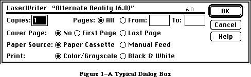 Figure 1–A Typical Dialog Box
By convention, a dialog box comes up slightly below the menu bar, is somewhat narrower than the screen, and is centered between the left and right edges of the screen. It may contain any or all of the following:
• informative or instructional text
• rectangles in which text may be entered (initially blank or
containing default text that can be edited)
• controls of any kind
• graphics (icons or QuickDraw pictures)
• anything else, as defined by the application
The user provides the necessary information in the dialog box, such as by entering text or clicking a check box. There’s usually a button labeled “OK” to tell the application to accept the information provided and perform the command, and a button labeled “Cancel” to cancel the command as though it had never been given (retracting all actions since its invocation). Some dialog boxes may use a more descriptive word than “OK”; for simplicity, this chapter will still refer to the button as the “OK button”. There may even be more than one button that will perform the command, each in a different way.
Most dialog boxes require the user to respond before doing anything else. Clicking a button to perform or cancel the command makes the box go away; clicking outside the dialog box only causes a beep from the Macintosh’s speaker. This type is called a modal dialog box because it puts the user in the state or “mode” of being able to work only inside the dialog box. A modal dialog box usually has the same general appearance as shown in Figure 1 above. One of the buttons in the dialog box may be outlined boldly. Pressing the Return key or the Enter key has the same effect as clicking the outlined button or, if none, the OK button; the particular button whose effect occurs is called the dialog’s default button and is the preferred (“safest”) button to use in the current situation. If there’s no boldly outlined or OK button, pressing Return or Enter will by convention have no effect.
Other dialog boxes do not require the user to respond before doing anything else; these are called modeless dialog boxes (see Figure 2). The user can, for example, do work in document windows on the desktop before clicking a button in the dialog box, and modeless dialog boxes can be set up to respond to the standard editing commands in the Edit menu. Clicking a button in a modeless dialog box will not make the box go away: The box will stay around so that the user can perform the command again. A Cancel button, if present, will simply stop the action currently being performed by the command; this would be useful for long printing or searching operations, for example.
Figure 1–A Typical Dialog Box
By convention, a dialog box comes up slightly below the menu bar, is somewhat narrower than the screen, and is centered between the left and right edges of the screen. It may contain any or all of the following:
• informative or instructional text
• rectangles in which text may be entered (initially blank or
containing default text that can be edited)
• controls of any kind
• graphics (icons or QuickDraw pictures)
• anything else, as defined by the application
The user provides the necessary information in the dialog box, such as by entering text or clicking a check box. There’s usually a button labeled “OK” to tell the application to accept the information provided and perform the command, and a button labeled “Cancel” to cancel the command as though it had never been given (retracting all actions since its invocation). Some dialog boxes may use a more descriptive word than “OK”; for simplicity, this chapter will still refer to the button as the “OK button”. There may even be more than one button that will perform the command, each in a different way.
Most dialog boxes require the user to respond before doing anything else. Clicking a button to perform or cancel the command makes the box go away; clicking outside the dialog box only causes a beep from the Macintosh’s speaker. This type is called a modal dialog box because it puts the user in the state or “mode” of being able to work only inside the dialog box. A modal dialog box usually has the same general appearance as shown in Figure 1 above. One of the buttons in the dialog box may be outlined boldly. Pressing the Return key or the Enter key has the same effect as clicking the outlined button or, if none, the OK button; the particular button whose effect occurs is called the dialog’s default button and is the preferred (“safest”) button to use in the current situation. If there’s no boldly outlined or OK button, pressing Return or Enter will by convention have no effect.
Other dialog boxes do not require the user to respond before doing anything else; these are called modeless dialog boxes (see Figure 2). The user can, for example, do work in document windows on the desktop before clicking a button in the dialog box, and modeless dialog boxes can be set up to respond to the standard editing commands in the Edit menu. Clicking a button in a modeless dialog box will not make the box go away: The box will stay around so that the user can perform the command again. A Cancel button, if present, will simply stop the action currently being performed by the command; this would be useful for long printing or searching operations, for example.
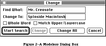 Figure 2–A Modeless Dialog Box
As shown in Figure 2, a modeless dialog box looks like a document window. It can be moved, made inactive and active again, or closed like any document window. When you’re done with the command and want the box to go away, you can click its close box or choose Close from the File menu when it’s the active window.
Dialog boxes may in fact require no response at all. For example, while an application is performing a time-consuming process, it can display a dialog box that contains only a message telling what it’s doing; then, when the process is complete, it can simply remove the dialog box.
The alert mechanism provides applications with a means of reporting errors or giving warnings. An alert box is similar to a modal dialog box, but it appears only when something has gone wrong or must be brought to the user’s attention. Its conventional placement is slightly farther below the menu bar than a dialog box. To assist the user who isn’t sure how to proceed when an alert box appears, the preferred button to use in the current situation is outlined boldly so it stands out from the other buttons in the alert box (see Figure 3). The outlined button is also the alert’s default button; if the user presses the Return key or the Enter key, the effect is the same as clicking this button.
Figure 2–A Modeless Dialog Box
As shown in Figure 2, a modeless dialog box looks like a document window. It can be moved, made inactive and active again, or closed like any document window. When you’re done with the command and want the box to go away, you can click its close box or choose Close from the File menu when it’s the active window.
Dialog boxes may in fact require no response at all. For example, while an application is performing a time-consuming process, it can display a dialog box that contains only a message telling what it’s doing; then, when the process is complete, it can simply remove the dialog box.
The alert mechanism provides applications with a means of reporting errors or giving warnings. An alert box is similar to a modal dialog box, but it appears only when something has gone wrong or must be brought to the user’s attention. Its conventional placement is slightly farther below the menu bar than a dialog box. To assist the user who isn’t sure how to proceed when an alert box appears, the preferred button to use in the current situation is outlined boldly so it stands out from the other buttons in the alert box (see Figure 3). The outlined button is also the alert’s default button; if the user presses the Return key or the Enter key, the effect is the same as clicking this button.
 Figure 3–A Typical Alert Box
There are three standard kinds of alerts—Stop, Note, and Caution—each indicated by a particular icon in the top left corner of the alert box. Figure 3 illustrates a Caution alert. The icons identifying Stop and Note alerts are similar; instead of a question mark, they show an exclamation point and an asterisk, respectively. Other alerts can have anything in the the top left corner, including blank space if desired.
The alert mechanism also provides another type of signal: Sound from the Macintosh’s speaker. The application can base its response on the number of consecutive times an alert occurs; the first time, it might simply beep, and thereafter it may present an alert box. The sound isn’t limited to a single beep but may be any sequence of tones, and may occur either alone or along with an alert box. As an error is repeated, there can also be a change in which button is the default button (perhaps from OK to Cancel). You can specify different responses for up to four occurrences of the same alert.
With Dialog Manager routines, you can create dialog boxes or invoke alerts. The Dialog Manager gets most of the descriptive information about the dialogs and alerts from resources in a resource file. The Dialog Manager calls the Resource Manager to read what it needs from the resource file into memory as necessary. In some cases you can modify the information after it’s been read into memory.
Four routines—HideDItem, ShowDItem, FindDItem, and UpdtDialog—have been added to the Dialog Manager.
Advanced programmers: The standard filterProc function called by
ModalDialog now returns 1 in itemHit and a
function result of TRUE only if the first item
is enabled.
Automatic scrolling is supported in editText items.
_______________________________________________________________________________
»DIALOG AND ALERT WINDOWS
_______________________________________________________________________________
A dialog box appears in a dialog window. When you call a Dialog Manager routine to create a dialog, you supply the same information as when you create a window with a Window Manager routine. For example, you supply the window definition ID, which determines how the window looks and behaves, and a rectangle that becomes the portRect of the window’s grafPort. You specify the window’s plane (which, by convention, should initially be the frontmost) and whether the window is visible or invisible. The dialog window is created as specified.
You can manipulate a dialog window just like any other window with Window Manager or QuickDraw routines, showing it, hiding it, moving it, changing its size or plane, or whatever— all, of course, in conformance with the Macintosh User Interface Guidelines. The Dialog Manager observes the clipping region of the dialog window’s grafPort, so if you want clipping to occur, you can set this region with a QuickDraw routine.
Similarly, an alert box appears in an alert window. You don’t have the same flexibility in defining and manipulating an alert window, however. The Dialog Manager chooses the window definition ID, so that all alert windows will have the standard appearance and behavior. The size and location of the box are supplied as part of the definition of the alert and are not easily changed. You don’t specify the alert window’s plane; it always comes up in front of all other windows. Since an alert box requires the user to respond before doing anything else, and the response makes the box go away, the application doesn’t do any manipulation of the alert window.
Figure 4 illustrates a document window, dialog window, and alert window, all overlapping on the desktop.
Figure 3–A Typical Alert Box
There are three standard kinds of alerts—Stop, Note, and Caution—each indicated by a particular icon in the top left corner of the alert box. Figure 3 illustrates a Caution alert. The icons identifying Stop and Note alerts are similar; instead of a question mark, they show an exclamation point and an asterisk, respectively. Other alerts can have anything in the the top left corner, including blank space if desired.
The alert mechanism also provides another type of signal: Sound from the Macintosh’s speaker. The application can base its response on the number of consecutive times an alert occurs; the first time, it might simply beep, and thereafter it may present an alert box. The sound isn’t limited to a single beep but may be any sequence of tones, and may occur either alone or along with an alert box. As an error is repeated, there can also be a change in which button is the default button (perhaps from OK to Cancel). You can specify different responses for up to four occurrences of the same alert.
With Dialog Manager routines, you can create dialog boxes or invoke alerts. The Dialog Manager gets most of the descriptive information about the dialogs and alerts from resources in a resource file. The Dialog Manager calls the Resource Manager to read what it needs from the resource file into memory as necessary. In some cases you can modify the information after it’s been read into memory.
Four routines—HideDItem, ShowDItem, FindDItem, and UpdtDialog—have been added to the Dialog Manager.
Advanced programmers: The standard filterProc function called by
ModalDialog now returns 1 in itemHit and a
function result of TRUE only if the first item
is enabled.
Automatic scrolling is supported in editText items.
_______________________________________________________________________________
»DIALOG AND ALERT WINDOWS
_______________________________________________________________________________
A dialog box appears in a dialog window. When you call a Dialog Manager routine to create a dialog, you supply the same information as when you create a window with a Window Manager routine. For example, you supply the window definition ID, which determines how the window looks and behaves, and a rectangle that becomes the portRect of the window’s grafPort. You specify the window’s plane (which, by convention, should initially be the frontmost) and whether the window is visible or invisible. The dialog window is created as specified.
You can manipulate a dialog window just like any other window with Window Manager or QuickDraw routines, showing it, hiding it, moving it, changing its size or plane, or whatever— all, of course, in conformance with the Macintosh User Interface Guidelines. The Dialog Manager observes the clipping region of the dialog window’s grafPort, so if you want clipping to occur, you can set this region with a QuickDraw routine.
Similarly, an alert box appears in an alert window. You don’t have the same flexibility in defining and manipulating an alert window, however. The Dialog Manager chooses the window definition ID, so that all alert windows will have the standard appearance and behavior. The size and location of the box are supplied as part of the definition of the alert and are not easily changed. You don’t specify the alert window’s plane; it always comes up in front of all other windows. Since an alert box requires the user to respond before doing anything else, and the response makes the box go away, the application doesn’t do any manipulation of the alert window.
Figure 4 illustrates a document window, dialog window, and alert window, all overlapping on the desktop.
 Figure 4–Dialog and Alert Windows
_______________________________________________________________________________
»DIALOGS, ALERTS, AND RESOURCES
_______________________________________________________________________________
To create a dialog, the Dialog Manager needs the same information about the dialog window as the Window Manager needs when it creates a new window: The window definition ID along with other information specific to this window. The Dialog Manager also needs to know what items the dialog box contains. You can store the needed information as a resource in a resource file and pass the resource ID to a function that will create the dialog. This type of resource, which is called a dialog template, is analogous to a window template, and the function, GetNewDialog, is similar to the Window Manager function GetNewWindow. The Dialog Manager calls the Resource Manager to read the dialog template from the resource file. It then incorporates the information in the template into a dialog data structure in memory, called a dialog record.
Similarly, the data that the Dialog Manager needs to create an alert is stored in an alert template in a resource file. The various routines for invoking alerts require the resource ID of the alert template as a parameter.
The information about all the items (text, controls, or graphics) in a dialog or alert box is stored in an item list in a resource file. The resource ID of the item list is included in the dialog or alert template. The item list in turn contains the resource IDs of any icons or QuickDraw pictures in the dialog or alert box, and possibly the resource IDs of control templates for controls in the box. After calling the Resource Manager to read a dialog or alert template into memory, the Dialog Manager calls it again to read in the item list. It then makes a copy of the item list and uses that copy; for this reason, item lists should always be purgeable resources. Finally, the Dialog Manager calls the Resource Manager to read in any individual items as necessary.
If desired, the application can gain some additional flexibility by calling the Resource Manager directly to read templates, item lists, or items from a resource file. For example, you can read in a dialog or alert template directly and modify some of the information in it before calling the routine to create the dialog or alert. Or, as an alternative to using a dialog template, you can read in a dialog’s item list directly and then pass a handle to it along with other information to a function that will create the dialog (NewDialog, analogous to the Window Manager function NewWindow).
Note: The use of dialog templates is recommended wherever possible; like
window templates, they isolate descriptive information from your
application code for ease of modification or translation to other
languages.
_______________________________________________________________________________
»COLOR ALERT AND DIALOG RESOURCES
_______________________________________________________________________________
You don’t have to call any new routines to create color alert or dialog boxes. Additional resources of types 'actb', 'dctb', and 'ictb' complement the existing 'ALRT', 'DLOG', and 'DITL' resources, and provide all the information needed to color dialog windows, controls, and text.
To create a dialog or alert box, the Dialog Manager needs the same information about the box as the Window Manager needs when it creates a new window. The structure of dialog color tables and alert color tables is similar to the window color table described in the Window Manager chapter, as shown in
Figure 5.
Figure 4–Dialog and Alert Windows
_______________________________________________________________________________
»DIALOGS, ALERTS, AND RESOURCES
_______________________________________________________________________________
To create a dialog, the Dialog Manager needs the same information about the dialog window as the Window Manager needs when it creates a new window: The window definition ID along with other information specific to this window. The Dialog Manager also needs to know what items the dialog box contains. You can store the needed information as a resource in a resource file and pass the resource ID to a function that will create the dialog. This type of resource, which is called a dialog template, is analogous to a window template, and the function, GetNewDialog, is similar to the Window Manager function GetNewWindow. The Dialog Manager calls the Resource Manager to read the dialog template from the resource file. It then incorporates the information in the template into a dialog data structure in memory, called a dialog record.
Similarly, the data that the Dialog Manager needs to create an alert is stored in an alert template in a resource file. The various routines for invoking alerts require the resource ID of the alert template as a parameter.
The information about all the items (text, controls, or graphics) in a dialog or alert box is stored in an item list in a resource file. The resource ID of the item list is included in the dialog or alert template. The item list in turn contains the resource IDs of any icons or QuickDraw pictures in the dialog or alert box, and possibly the resource IDs of control templates for controls in the box. After calling the Resource Manager to read a dialog or alert template into memory, the Dialog Manager calls it again to read in the item list. It then makes a copy of the item list and uses that copy; for this reason, item lists should always be purgeable resources. Finally, the Dialog Manager calls the Resource Manager to read in any individual items as necessary.
If desired, the application can gain some additional flexibility by calling the Resource Manager directly to read templates, item lists, or items from a resource file. For example, you can read in a dialog or alert template directly and modify some of the information in it before calling the routine to create the dialog or alert. Or, as an alternative to using a dialog template, you can read in a dialog’s item list directly and then pass a handle to it along with other information to a function that will create the dialog (NewDialog, analogous to the Window Manager function NewWindow).
Note: The use of dialog templates is recommended wherever possible; like
window templates, they isolate descriptive information from your
application code for ease of modification or translation to other
languages.
_______________________________________________________________________________
»COLOR ALERT AND DIALOG RESOURCES
_______________________________________________________________________________
You don’t have to call any new routines to create color alert or dialog boxes. Additional resources of types 'actb', 'dctb', and 'ictb' complement the existing 'ALRT', 'DLOG', and 'DITL' resources, and provide all the information needed to color dialog windows, controls, and text.
To create a dialog or alert box, the Dialog Manager needs the same information about the box as the Window Manager needs when it creates a new window. The structure of dialog color tables and alert color tables is similar to the window color table described in the Window Manager chapter, as shown in
Figure 5.
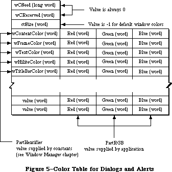 Figure 5–Color Table for Dialogs and Alerts.
The calls Alert, CautionAlert, StopAlert, and NoteAlert look for a resource of type 'actb' with the same resource ID as the alert. GetNewDialog looks for a resource of type 'dctb' with the same resource ID as the dialog. These resources contain color tables identical to the 'wctb' color tables described in the Window Manager GetNewCWindow call. If an 'actb' or 'dctb' resource is present, then the window created will be a cGrafPort, created with a NewCWindow call. If the ctSize field of a 'dctb' or 'actb' resource is –1, the default window colors will be used.
To include a color icon in a dialog box, add a resource of type 'cicn' with the same resource ID as an old-style icon. The Dialog Manager will then access the icon with the QuickDraw routine GetCIcon.
To include a version 2 picture in a dialog, create a color table for the dialog to cause the dialog to use a cGrafPort. See the Color QuickDraw chapter for more information on the use of color pictures.
To color controls in a dialog, or to change the color, style, font, or size of text within a dialog, include an 'ictb' resource as described in the following section.
Color table resources 'actb' and 'dctb' are treated the same as 'ALRT' resources and 'DLOG' resources. The 'ictb' resource is handled just like the
'DITL' resource. These resources are preloaded and made nonpurgeable by CouldAlert and CouldDialog, and their original purge state is restored by FreeAlert and FreeDialog.
_______________________________________________________________________________
»ITEM LISTS IN MEMORY
_______________________________________________________________________________
This section discusses the contents of an item list once it’s been read into memory from a resource file and the Dialog Manager has set it up as necessary to be able to work with it.
An item list in memory contains the following information for each item:
• The type of item. This includes not only whether the item is a control,
text, or whatever, but also whether the Dialog Manager should return to
the application when the item is clicked.
• A handle to the item or, for special application-defined items, a
pointer to a procedure that draws the item.
• A display rectangle, which determines the location of the item within
the dialog or alert box.
These are discussed below along with item numbers, which identify particular items in the item list.
There’s a Dialog Manager procedure that, given a pointer to a dialog record and an item number, sets or returns that item’s type, handle (or procedure pointer), and display rectangle.
_______________________________________________________________________________
»Item Types
The item type is specified by a predefined constant or combination of constants, as listed below. Figure 6 illustrates some of these item types.
Figure 5–Color Table for Dialogs and Alerts.
The calls Alert, CautionAlert, StopAlert, and NoteAlert look for a resource of type 'actb' with the same resource ID as the alert. GetNewDialog looks for a resource of type 'dctb' with the same resource ID as the dialog. These resources contain color tables identical to the 'wctb' color tables described in the Window Manager GetNewCWindow call. If an 'actb' or 'dctb' resource is present, then the window created will be a cGrafPort, created with a NewCWindow call. If the ctSize field of a 'dctb' or 'actb' resource is –1, the default window colors will be used.
To include a color icon in a dialog box, add a resource of type 'cicn' with the same resource ID as an old-style icon. The Dialog Manager will then access the icon with the QuickDraw routine GetCIcon.
To include a version 2 picture in a dialog, create a color table for the dialog to cause the dialog to use a cGrafPort. See the Color QuickDraw chapter for more information on the use of color pictures.
To color controls in a dialog, or to change the color, style, font, or size of text within a dialog, include an 'ictb' resource as described in the following section.
Color table resources 'actb' and 'dctb' are treated the same as 'ALRT' resources and 'DLOG' resources. The 'ictb' resource is handled just like the
'DITL' resource. These resources are preloaded and made nonpurgeable by CouldAlert and CouldDialog, and their original purge state is restored by FreeAlert and FreeDialog.
_______________________________________________________________________________
»ITEM LISTS IN MEMORY
_______________________________________________________________________________
This section discusses the contents of an item list once it’s been read into memory from a resource file and the Dialog Manager has set it up as necessary to be able to work with it.
An item list in memory contains the following information for each item:
• The type of item. This includes not only whether the item is a control,
text, or whatever, but also whether the Dialog Manager should return to
the application when the item is clicked.
• A handle to the item or, for special application-defined items, a
pointer to a procedure that draws the item.
• A display rectangle, which determines the location of the item within
the dialog or alert box.
These are discussed below along with item numbers, which identify particular items in the item list.
There’s a Dialog Manager procedure that, given a pointer to a dialog record and an item number, sets or returns that item’s type, handle (or procedure pointer), and display rectangle.
_______________________________________________________________________________
»Item Types
The item type is specified by a predefined constant or combination of constants, as listed below. Figure 6 illustrates some of these item types.
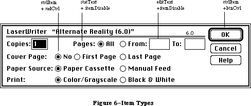 Figure 6–Item Types
Item type Meaning
ctrlItem+btnCtrl A standard button control.
ctrlItem+chkCtrl A standard check box control.
ctrlItem+radCtrl A standard radio button control.
ctrlItem+resCtrl A control defined in a control template
in a resource file.
statText Static text; text that cannot be edited.
editText (Dialogs only) Text that can be edited;
the Dialog Manager accepts text typed by
the user and allows editing.
iconItem An icon.
picItem A QuickDraw picture.
userItem (Dialogs only) An application-defined item,
such as a picture whose appearance changes.
itemDisable+<any The item is disabled (the Dialog Manager doesn’t
of the above> report events involving this item).
The text of an editText item may initially be either default text or empty. Text entry and editing is handled in the conventional way, as in TextEdit—in fact, the Dialog Manager calls TextEdit to handle it:
• Clicking in the item displays a blinking vertical bar, indicating
an insertion point where text may be entered.
• Dragging over text in the item selects that text, and double-clicking
selects a word; the selection is highlighted and then replaced by
what the user types.
• Clicking or dragging while holding down the Shift key extends or
shortens the current selection.
• The Backspace key deletes the current selection or the character
preceding the insertion point.
The Tab key advances to the next editText item in the item list, wrapping around to the first if there aren’t any more. In an alert box or a modal dialog box (regardless of whether it contains an editText item), the Return key or Enter key has the same effect as clicking the default button; for alerts, the default button is identified in the alert template, whereas for modal dialogs it’s always the first item in the item list.
If itemDisable is specified for an item, the Dialog Manager doesn’t let the application know about events involving that item. For example, you may not have to be informed every time the user types a character or clicks in an editText item, but may only need to look at the text when the OK button is clicked. In this case, the editText item would be disabled. Standard buttons and check boxes should always be enabled, so your application will know when they’ve been clicked.
Warning: Don’t confuse disabling a control with making one “inactive”
with the Control Manager procedure HiliteControl: When you
want a control not to respond at all to being clicked, you
make it inactive. An inactive control is highlighted to show
that it’s inactive, while disabling a control doesn’t affect
its appearance.
_______________________________________________________________________________
»Item Handle or Procedure Pointer
The item list contains the following information for the various types of items:
Item type Contents
any ctrlItem A control handle
statText A handle to the text
editText A handle to the current text
iconItem A handle to the icon
picItem A picture handle
userItem A procedure pointer
The procedure for a userItem draws the item; for example, if the item is a clock, it will draw the clock with the current time displayed. When this procedure is called, the current port will have been set by the Dialog Manager to the dialog window’s grafPort. The procedure must have two parameters, a window pointer and an item number. For example, this is how it would be declared if it were named MyItem:
PROCEDURE MyItem (theWindow: WindowPtr; itemNo: INTEGER);
TheWindow is a pointer to the dialog window; in case the procedure draws in more than one dialog window, this parameter tells it which one to draw in. ItemNo is the item number; in case the procedure draws more than one item, this parameter tells it which one to draw.
_______________________________________________________________________________
»Display Rectangle
Each item in the item list is displayed within its display rectangle:
• For controls, the display rectangle becomes the control’s
enclosing rectangle.
• For an editText item, it becomes TextEdit’s destination rectangle
and view rectangle. Word wraparound occurs, and the text is clipped
if there’s more than will fit in the rectangle. In addition, the
Dialog Manager uses the QuickDraw procedure FrameRect to draw a
rectangle three pixels outside the display rectangle.
• StatText items are displayed in exactly the same way as editText
items, except that a rectangle isn’t drawn outside the display rectangle.
• Icons and QuickDraw pictures are scaled to fit the display rectangle.
For pictures, the Window Manager calls the QuickDraw procedure
DrawPicture and passes it the display rectangle.
• If the procedure for a userItem draws outside the item’s display
rectangle, the drawing is clipped to the display rectangle.
Note: Clicking anywhere within the display rectangle is considered a
click in that item. If display rectangles overlap, a click in
the overlapping area is considered a click in whichever item
comes first in the item list.
By giving an item a display rectangle that’s off the screen, you can make the item invisible. This might be useful, for example, if your application needs to display a number of dialog boxes that are similar except that one item is missing or different in some of them. You can use a single dialog box in which the item or items that aren’t currently relevant are invisible. To remove an item or make one reappear, you just change its display rectangle (and call the Window Manager procedure InvalRect to accumulate the changed area into the dialog window’s update region). The QuickDraw procedure OffsetRect is convenient for moving an item off the screen and then on again later. Note the following, however:
• You shouldn’t make an editText item invisible, because it may cause
strange things to happen. If one of several editText items is invisible,
for example, pressing the Tab key may make the insertion point disappear.
However, if you do make this type of item invisible, remember that the
changed area includes the rectangle that’s three pixels outside the
item’s display rectangle.
• The rectangle for a statText item must always be at least as wide as
the first character of the text; a good rule of thumb is to make it
at least 20 pixels wide.
• To change text in a statText item, it’s easier to use the Dialog
Manager procedure ParamText (as described later in the “Dialog Manager
Routines” section).
_______________________________________________________________________________
»Item Numbers
Each item in an item list is identified by an item number, which is simply the index of the item in the list (starting from 1). By convention, the first item in an alert’s item list should be the OK button (or, if none, then one of the buttons that will perform the command) and the second item should be the Cancel button. The Dialog Manager provides predefined constants equal to the item numbers for OK and Cancel:
CONST ok = 1;
cancel = 2;
In a modal dialog’s item list, the first item is assumed to be the dialog’s default button; if the user presses the Return key or Enter key, the Dialog Manager normally returns item number 1, just as when that item is actually clicked. To conform to the Macintosh User Interface Guidelines, the application should boldly outline the dialog’s default button if it isn’t the OK button. The best way to do this is with a userItem. To allow for changes in the default button’s size or location, the userItem should identify which button to outline by its item number and then use that number to get the button’s display rectangle. The following QuickDraw calls will outline the rectangle in the standard way:
PenSize(3,3);
InsetRect(displayRect,–4,–4);
FrameRoundRect(displayRect,16,16)
Warning: If the first item in a modal dialog’s item list isn’t an OK
button and you don’t boldly outline it, you should set up the
dialog to ignore Return and Enter. To learn how to do this,
see ModalDialog under “Handling Dialog Events” in the “Dialog
Manager Routines” section.
_______________________________________________________________________________
»COLOR DIALOG ITEM LISTS
_______________________________________________________________________________
This section discusses the contents of an item list after it’s been read into memory from a resource file. If a resource of type 'ictb' is present with the same resource ID as the 'DITL' resource (in addition to the presence of the
'dctb' or 'actb' resources), then the statText, editText, and control items in the dialog or alert boxes are drawn using the colors and text styles indicated by the item color table record contained in the resource.
Note: Neither the display device nor the dialog box needs to be in color,
but a dialog or alert color table must exist to include an item color
table (even if the item color table only describes statText and editText
style changes and has no actual color information).
Figure 7 shows how a dialog color table stores item color table records.
Figure 6–Item Types
Item type Meaning
ctrlItem+btnCtrl A standard button control.
ctrlItem+chkCtrl A standard check box control.
ctrlItem+radCtrl A standard radio button control.
ctrlItem+resCtrl A control defined in a control template
in a resource file.
statText Static text; text that cannot be edited.
editText (Dialogs only) Text that can be edited;
the Dialog Manager accepts text typed by
the user and allows editing.
iconItem An icon.
picItem A QuickDraw picture.
userItem (Dialogs only) An application-defined item,
such as a picture whose appearance changes.
itemDisable+<any The item is disabled (the Dialog Manager doesn’t
of the above> report events involving this item).
The text of an editText item may initially be either default text or empty. Text entry and editing is handled in the conventional way, as in TextEdit—in fact, the Dialog Manager calls TextEdit to handle it:
• Clicking in the item displays a blinking vertical bar, indicating
an insertion point where text may be entered.
• Dragging over text in the item selects that text, and double-clicking
selects a word; the selection is highlighted and then replaced by
what the user types.
• Clicking or dragging while holding down the Shift key extends or
shortens the current selection.
• The Backspace key deletes the current selection or the character
preceding the insertion point.
The Tab key advances to the next editText item in the item list, wrapping around to the first if there aren’t any more. In an alert box or a modal dialog box (regardless of whether it contains an editText item), the Return key or Enter key has the same effect as clicking the default button; for alerts, the default button is identified in the alert template, whereas for modal dialogs it’s always the first item in the item list.
If itemDisable is specified for an item, the Dialog Manager doesn’t let the application know about events involving that item. For example, you may not have to be informed every time the user types a character or clicks in an editText item, but may only need to look at the text when the OK button is clicked. In this case, the editText item would be disabled. Standard buttons and check boxes should always be enabled, so your application will know when they’ve been clicked.
Warning: Don’t confuse disabling a control with making one “inactive”
with the Control Manager procedure HiliteControl: When you
want a control not to respond at all to being clicked, you
make it inactive. An inactive control is highlighted to show
that it’s inactive, while disabling a control doesn’t affect
its appearance.
_______________________________________________________________________________
»Item Handle or Procedure Pointer
The item list contains the following information for the various types of items:
Item type Contents
any ctrlItem A control handle
statText A handle to the text
editText A handle to the current text
iconItem A handle to the icon
picItem A picture handle
userItem A procedure pointer
The procedure for a userItem draws the item; for example, if the item is a clock, it will draw the clock with the current time displayed. When this procedure is called, the current port will have been set by the Dialog Manager to the dialog window’s grafPort. The procedure must have two parameters, a window pointer and an item number. For example, this is how it would be declared if it were named MyItem:
PROCEDURE MyItem (theWindow: WindowPtr; itemNo: INTEGER);
TheWindow is a pointer to the dialog window; in case the procedure draws in more than one dialog window, this parameter tells it which one to draw in. ItemNo is the item number; in case the procedure draws more than one item, this parameter tells it which one to draw.
_______________________________________________________________________________
»Display Rectangle
Each item in the item list is displayed within its display rectangle:
• For controls, the display rectangle becomes the control’s
enclosing rectangle.
• For an editText item, it becomes TextEdit’s destination rectangle
and view rectangle. Word wraparound occurs, and the text is clipped
if there’s more than will fit in the rectangle. In addition, the
Dialog Manager uses the QuickDraw procedure FrameRect to draw a
rectangle three pixels outside the display rectangle.
• StatText items are displayed in exactly the same way as editText
items, except that a rectangle isn’t drawn outside the display rectangle.
• Icons and QuickDraw pictures are scaled to fit the display rectangle.
For pictures, the Window Manager calls the QuickDraw procedure
DrawPicture and passes it the display rectangle.
• If the procedure for a userItem draws outside the item’s display
rectangle, the drawing is clipped to the display rectangle.
Note: Clicking anywhere within the display rectangle is considered a
click in that item. If display rectangles overlap, a click in
the overlapping area is considered a click in whichever item
comes first in the item list.
By giving an item a display rectangle that’s off the screen, you can make the item invisible. This might be useful, for example, if your application needs to display a number of dialog boxes that are similar except that one item is missing or different in some of them. You can use a single dialog box in which the item or items that aren’t currently relevant are invisible. To remove an item or make one reappear, you just change its display rectangle (and call the Window Manager procedure InvalRect to accumulate the changed area into the dialog window’s update region). The QuickDraw procedure OffsetRect is convenient for moving an item off the screen and then on again later. Note the following, however:
• You shouldn’t make an editText item invisible, because it may cause
strange things to happen. If one of several editText items is invisible,
for example, pressing the Tab key may make the insertion point disappear.
However, if you do make this type of item invisible, remember that the
changed area includes the rectangle that’s three pixels outside the
item’s display rectangle.
• The rectangle for a statText item must always be at least as wide as
the first character of the text; a good rule of thumb is to make it
at least 20 pixels wide.
• To change text in a statText item, it’s easier to use the Dialog
Manager procedure ParamText (as described later in the “Dialog Manager
Routines” section).
_______________________________________________________________________________
»Item Numbers
Each item in an item list is identified by an item number, which is simply the index of the item in the list (starting from 1). By convention, the first item in an alert’s item list should be the OK button (or, if none, then one of the buttons that will perform the command) and the second item should be the Cancel button. The Dialog Manager provides predefined constants equal to the item numbers for OK and Cancel:
CONST ok = 1;
cancel = 2;
In a modal dialog’s item list, the first item is assumed to be the dialog’s default button; if the user presses the Return key or Enter key, the Dialog Manager normally returns item number 1, just as when that item is actually clicked. To conform to the Macintosh User Interface Guidelines, the application should boldly outline the dialog’s default button if it isn’t the OK button. The best way to do this is with a userItem. To allow for changes in the default button’s size or location, the userItem should identify which button to outline by its item number and then use that number to get the button’s display rectangle. The following QuickDraw calls will outline the rectangle in the standard way:
PenSize(3,3);
InsetRect(displayRect,–4,–4);
FrameRoundRect(displayRect,16,16)
Warning: If the first item in a modal dialog’s item list isn’t an OK
button and you don’t boldly outline it, you should set up the
dialog to ignore Return and Enter. To learn how to do this,
see ModalDialog under “Handling Dialog Events” in the “Dialog
Manager Routines” section.
_______________________________________________________________________________
»COLOR DIALOG ITEM LISTS
_______________________________________________________________________________
This section discusses the contents of an item list after it’s been read into memory from a resource file. If a resource of type 'ictb' is present with the same resource ID as the 'DITL' resource (in addition to the presence of the
'dctb' or 'actb' resources), then the statText, editText, and control items in the dialog or alert boxes are drawn using the colors and text styles indicated by the item color table record contained in the resource.
Note: Neither the display device nor the dialog box needs to be in color,
but a dialog or alert color table must exist to include an item color
table (even if the item color table only describes statText and editText
style changes and has no actual color information).
Figure 7 shows how a dialog color table stores item color table records.
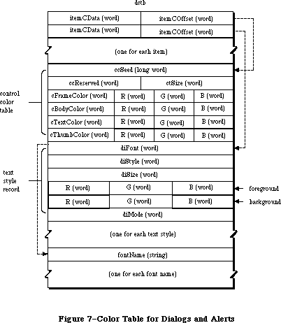 Figure 7–Color Table for Dialogs and Alerts.
The record starts with an array of two-word entries for each item in the matching dialog item list. The first word (itemCData) is the length of the entry if the item is a control, or it is a word of flags if the item is an editText or statText item. The second word (itemCOffset) is an offset from the beginning of the record to the color item entry. This color record is used only for controls and text; icons and pictures have a different method of describing associated colors. Set the itemCData and itemCOffset fields to zero for controls or text without colors or font changes.
If the item is an editText or statText item, the bits in the itemCData field determine which fields of the text style record to use; these bit equates are listed in the following table.
Bit Meaning
0 Change the font family
1 Change the font face
2 Change the font size
3 Change the font forecolor
4 Add the font size
13 Change the font backcolor
14 Change the font mode
15 The font field is an offset to the name.
Note: Multiple text items can share the same font name.
The itemCData field for text items contains a superset of the flags passed as the mode word to the TextEdit routine TESetStyle. The constants defined for that routine include:
CONST
{ Constants for TextEdit and dialog boxes }
TEdoFont = 1; {set font (family) number}
TEdoFace = 2; {set character style}
TEdoSize = 4; {set type size}
TEdoColor = 8; {set foreground color}
TEdoAll = 15; {set all attributes}
TEaddSize = 16; {adjust type size}
{ Constants for dialog boxes only }
doBColor = 8192; {set backgound color}
doMode = 16384; {set txMode}
doFontName = 32768; {set txFont from name}
The text style record indicated by itemCOffset must be 20 bytes long, as shown in Figure 7. Multiple statText and editText items can use the same text style record. To display text in the standard font, color, size, and style, set the itemCData and itemCOffset to zero. Allocate space for all fields in the style table, even if they are not used. Even if only the first few items of the dialog box have color style information, there must be room for all of the items actually in the box (with the data and offset words of the unused entries set to zero).
For controls, the colors are described by a color table identical to the contents of a 'cctb' resource used by a GetNewCControl call. Multiple controls can use the same color table. To display a control in the default colors, set the itemCData and itemCOffset fields to zero. The length of the control color table should be the header size of eight bytes plus the eight-byte ColorSpec record for each entry in the color table.
The doFontName array is optional. However, it’s important to point to the name of the font instead of just including the font number. Fonts may be renumbered by font installers like the Font/DA Mover as the fonts are moved, so it is safest to rely on getting the right font by referring to the name.
Figure 7–Color Table for Dialogs and Alerts.
The record starts with an array of two-word entries for each item in the matching dialog item list. The first word (itemCData) is the length of the entry if the item is a control, or it is a word of flags if the item is an editText or statText item. The second word (itemCOffset) is an offset from the beginning of the record to the color item entry. This color record is used only for controls and text; icons and pictures have a different method of describing associated colors. Set the itemCData and itemCOffset fields to zero for controls or text without colors or font changes.
If the item is an editText or statText item, the bits in the itemCData field determine which fields of the text style record to use; these bit equates are listed in the following table.
Bit Meaning
0 Change the font family
1 Change the font face
2 Change the font size
3 Change the font forecolor
4 Add the font size
13 Change the font backcolor
14 Change the font mode
15 The font field is an offset to the name.
Note: Multiple text items can share the same font name.
The itemCData field for text items contains a superset of the flags passed as the mode word to the TextEdit routine TESetStyle. The constants defined for that routine include:
CONST
{ Constants for TextEdit and dialog boxes }
TEdoFont = 1; {set font (family) number}
TEdoFace = 2; {set character style}
TEdoSize = 4; {set type size}
TEdoColor = 8; {set foreground color}
TEdoAll = 15; {set all attributes}
TEaddSize = 16; {adjust type size}
{ Constants for dialog boxes only }
doBColor = 8192; {set backgound color}
doMode = 16384; {set txMode}
doFontName = 32768; {set txFont from name}
The text style record indicated by itemCOffset must be 20 bytes long, as shown in Figure 7. Multiple statText and editText items can use the same text style record. To display text in the standard font, color, size, and style, set the itemCData and itemCOffset to zero. Allocate space for all fields in the style table, even if they are not used. Even if only the first few items of the dialog box have color style information, there must be room for all of the items actually in the box (with the data and offset words of the unused entries set to zero).
For controls, the colors are described by a color table identical to the contents of a 'cctb' resource used by a GetNewCControl call. Multiple controls can use the same color table. To display a control in the default colors, set the itemCData and itemCOffset fields to zero. The length of the control color table should be the header size of eight bytes plus the eight-byte ColorSpec record for each entry in the color table.
The doFontName array is optional. However, it’s important to point to the name of the font instead of just including the font number. Fonts may be renumbered by font installers like the Font/DA Mover as the fonts are moved, so it is safest to rely on getting the right font by referring to the name.
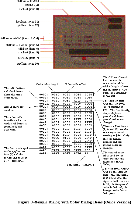 Figure 8–Sample Dialog with Color Dialog Items (Color Version).
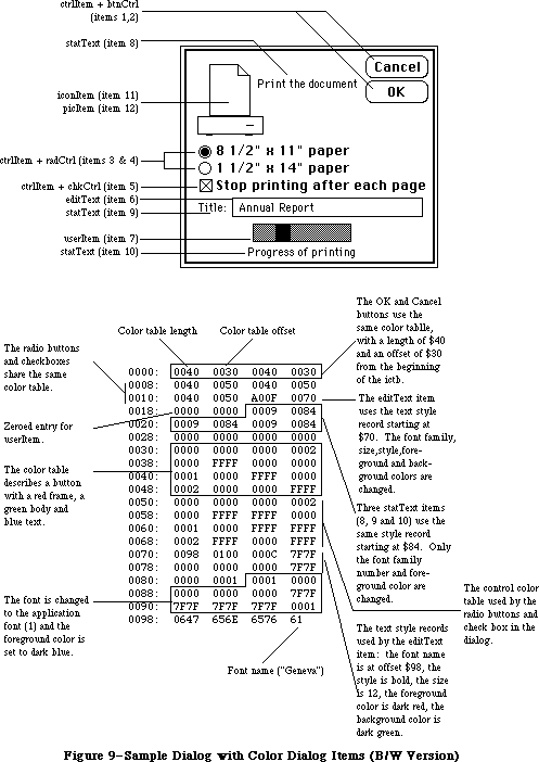 Figure 9–Sample Dialog with Color Dialog Items (B/W Version).
_______________________________________________________________________________
»USING COLOR DIALOGS AND ALERTS
_______________________________________________________________________________
The dialog box shown in Figure 8 contains 12 different dialog items. Some of these items—the OK and Cancel buttons, the radio buttons and the check box, and the editText and statText items—contain color information. The table shown in the figure contains the hexadecimal description of the dialog items. PicItems, iconItems, resCtrls and userItems should have zeroed entries for both fields. All items in the dialog should have a field, whether or not the item uses the new features.
Your application can create a dialog or alert, with color dialog items, within a resource file, and then use the GetNewDialog routine with the dialog’s resource ID. You can also use the NewCDialog routine to create a dialog or alert within an application, passing a handle to the dialog’s item list.
_______________________________________________________________________________
»DIALOG RECORDS
_______________________________________________________________________________
To create a dialog, you pass information to the Dialog Manager in a dialog template and in individual parameters, or only in parameters; in either case, the Dialog Manager incorporates the information into a dialog record. The dialog record contains the window record for the dialog window, a handle to the dialog’s item list, and some additional fields. The Dialog Manager creates the dialog window by calling the Window Manager function NewWindow and then setting the window class in the window record to indicate that it’s a dialog window. The routine that creates the dialog returns a pointer to the dialog record, which you use thereafter to refer to the dialog in Dialog Manager routines or even in Window Manager or QuickDraw routines (see “Dialog Pointers” below). The Dialog Manager provides routines for handling events in the dialog window and disposing of the dialog when you’re done.
The data type for a dialog record is called DialogRecord. You can do all the necessary operations on a dialog without accessing the fields of the dialog record directly; for advanced programmers, however, the exact structure of a dialog record is given under “The DialogRecord Data Type” below.
_______________________________________________________________________________
»Dialog Pointers
There are two types of dialog pointer, DialogPtr and DialogPeek, analogous to the window pointer types WindowPtr and WindowPeek. Most programmers will only need to use DialogPtr.
The Dialog Manager defines the following type of dialog pointer:
TYPE DialogPtr = WindowPtr;
It can do this because the first field of a dialog record contains the window record for the dialog window. This type of pointer can be used to access fields of the window record or can be passed to Window Manager routines that expect window pointers as parameters. Since the WindowPtr data type is itself defined as GrafPtr, this type of dialog pointer can also be used to access fields of the dialog window’s grafPort or passed to QuickDraw routines that expect pointers to grafPorts as parameters.
For programmers who want to access dialog record fields beyond the window record, the Dialog Manager also defines the following type of dialog pointer:
TYPE DialogPeek = ^DialogRecord;
Assembly-language note: From assembly language, of course, there’s no
type checking on pointers, and the two types
of pointer are equal.
_______________________________________________________________________________
»The DialogRecord Data Type
For those who want to know more about the data structure of a dialog record, the exact structure is given here.
TYPE DialogRecord = RECORD
window: WindowRecord; {dialog window}
items: Handle; {item list}
textH: TEHandle; {current editText item}
editField: INTEGER; {editText item number minus 1}
editOpen: INTEGER; {used internally}
aDefItem: INTEGER {default button item number}
END;
The window field contains the window record for the dialog window. The items field contains a handle to the item list used for the dialog. (Remember that after reading an item list from a resource file, the Dialog Manager makes a copy of it and uses that copy.)
Note: To get or change information about an item in a dialog, you pass the
dialog pointer and the item number to a Dialog Manager procedure.
You’ll never access information directly through the handle to the
item list.
The Dialog Manager uses the next three fields when there are one or more editText items in the dialog. If there’s more than one such item, these fields apply to the one that currently is selected or displays the insertion point. The textH field contains the handle to the edit record used by TextEdit. EditField is 1 less than the item number of the current editText item, or –1 if there’s no editText item in the dialog. The editOpen field is used internally by the Dialog Manager.
Note: Actually, a single edit record is shared by all editText items; any
changes you make to it will apply to all such items. See the TextEdit
chapter for details about what kinds of changes you can make.
The aDefItem field is used for modal dialogs and alerts, which are treated internally as special modal dialogs. It contains the item number of the default button. The default button for a modal dialog is the first item in the item list, so this field contains 1 for modal dialogs. The default button for an alert is specified in the alert template; see the following section for more information.
_______________________________________________________________________________
»ALERTS
_______________________________________________________________________________
When you call a Dialog Manager routine to invoke an alert, you pass it the resource ID of the alert template, which contains the following:
• A rectangle, given in global coordinates, which determines the alert
window’s size and location. It becomes the portRect of the window’s
grafPort. To allow for the menu bar and the border around the portRect,
the top coordinate of the rectangle should be at least 25 points below
the top of the screen.
• The resource ID of the item list for the alert.
• Information about exactly what should happen at each stage of the alert.
Every alert has four stages, corresponding to consecutive occurrences of the alert: The first three stages correspond to the first three occurrences, while the fourth stage includes the fourth occurrence and any beyond the fourth. (The Dialog Manager compares the current alert’s resource ID to the last alert’s resource ID to determine whether it’s the same alert.) The actions for each stage are specified by the following three pieces of information:
• which is the default button—the OK button (or, if none, a button that
will perform the command) or the Cancel button
• whether the alert box is to be drawn
• which of four sounds should be emitted at this stage of the alert
The alert sounds are determined by a sound procedure that emits one of up to four tones or sequences of tones. The sound procedure has one parameter, an integer from 0 to 3; it can emit any sound for each of these numbers, which identify the sounds in the alert template. For example, you might declare a sound procedure named MySound as follows:
PROCEDURE MySound (soundNo: INTEGER);
If you don’t write your own sound procedure, the Dialog Manager uses the standard one: Sound number 0 represents no sound and sound numbers 1 through 3 represent the corresponding number of short beeps, each of the same pitch and duration. The volume of each beep depends on the current speaker volume setting, which the user can adjust with the Control Panel desk accessory. If the user has set the speaker volume to 0, the menu bar will blink in place of each beep.
For example, if the second stage of an alert is to cause a beep and no alert box, you can just specify the following for that stage in the alert template: Don’t draw the alert box, and use sound number 1. If instead you want, say, two successive beeps of different pitch, you need to write a procedure that will emit that sound for a particular sound number, and specify that number in the alert template. The Macintosh Operating System includes routines for emitting sound; see the Sound Driver chapter, and also the simple SysBeep procedure in the Operating System Utilties chapter. (The standard sound procedure calls SysBeep.)
Note: When the Dialog Manager detects a click outside an alert box or a
modal dialog box, it emits sound number 1; thus, for consistency
with the Macintosh User Interface Guidelines, sound number 1 should
always be a single beep.
Internally, alerts are treated as special modal dialogs. The alert routine creates the alert window by calling NewDialog. The Dialog Manager works from the dialog record created by NewDialog, just as when it operates on a dialog window, but it disposes of the window before returning to the application. Normally your application won’t access the dialog record for an alert; however, there is a way that this can happen: For any alert, you can specify a procedure that will be executed repeatedly during the alert, and this procedure may access the dialog record. For details, see the alert routines under
“Invoking Alerts” in the “Dialog Manager Routines” section.
_______________________________________________________________________________
»USING THE DIALOG MANAGER
_______________________________________________________________________________
Before using the Dialog Manager, you must initialize QuickDraw, the Font Manager, the Window Manager, the Menu Manager, and TextEdit, in that order. The first Dialog Manager routine to call is InitDialogs, which initializes the Dialog Manager. If you want the font in your dialog and alert windows to be other than the system font, call SetDAFont to change the font.
Where appropriate in your program, call NewDialog or GetNewDialog to create any dialogs you need. Usually you’ll call GetNewDialog, which takes descriptive information about the dialog from a dialog template in a resource file. You can instead pass the information in individual parameters to NewDialog. In either case, you can supply a pointer to the storage for the dialog record or let it be allocated by the Dialog Manager. When you no longer need a dialog, you’ll usually call CloseDialog if you supplied the storage, or DisposDialog if not.
In most cases, you probably won’t have to make any changes to the dialogs from the way they’re defined in the resource file. However, if you should want to modify an item in a dialog, you can call GetDItem to get the information about the item and SetDItem to change it. In particular, SetDItem is the routine to use for installing a userItem. In some cases it may be appropriate to call some other Toolbox routine to change the item; for example, to change or move a control in a dialog, you would get its handle from GetDItem and then call the appropriate Control Manager routine. There are also two procedures specifically for accessing or setting the content of a text item in a dialog box: GetIText and SetIText.
To handle events in a modal dialog, just call the ModalDialog procedure after putting up the dialog box. If your application includes any modeless dialog boxes, you’ll pass events to IsDialogEvent to learn whether they need to be handled as part of a dialog, and then usually call DialogSelect if so. Before calling DialogSelect, however, you should check whether the user has given the keyboard equivalent of a command, and you may want to check for other special cases, depending on your application. You can support the use of the standard editing commands in a modeless dialog’s editText items with DlgCut, DlgCopy, DlgPaste, and DlgDelete.
A dialog box that contains editText items normally comes up with the insertion point in the first such item in its item list. You may instead want to bring up a dialog box with text selected in an editText item, or to cause an insertion point or text selection to reappear after the user has made an error in entering text. For example, the user who accidentally types nonnumeric input when a number is required can be given the opportunity to type the entry again. The SelIText procedure makes this possible.
For alerts, if you want other sounds besides the standard ones (up to three short beeps), write your own sound procedure and call ErrorSound to make it the current sound procedure. To invoke a particular alert, call one of the alert routines: StopAlert, NoteAlert, or CautionAlert for one of the standard kinds of alert, or Alert for an alert defined to have something other than a standard icon (or nothing at all) in its top left corner.
If you’re going to invoke a dialog or alert when the resource file might not be accessible, first call CouldDialog or CouldAlert, which will make the dialog or alert template and related resources unpurgeable. You can later make them purgeable again by calling FreeDialog or FreeAlert.
Finally, you can substitute text in statText items with text that you specify in the ParamText procedure. This means, for example, that a document name supplied by the user can appear in an error message.
_______________________________________________________________________________
»DIALOG MANAGER ROUTINES
_______________________________________________________________________________
»Initialization
PROCEDURE InitDialogs (resumeProc: ProcPtr);
Call InitDialogs once before all other Dialog Manager routines, to initialize the Dialog Manager. InitDialogs does the following initialization:
• It saves the pointer passed in resumeProc, if any, for access by the
System Error Handler in case a fatal system error occurs. ResumeProc
can be a pointer to a resume procedure, as described in the System
Error Handler chapter, or NIL if no such procedure is desired.
Assembly-language note: InitDialogs stores the address of the resume
procedure in a global variable named ResumeProc.
• It installs the standard sound procedure.
• It passes empty strings to ParamText.
PROCEDURE ErrorSound (soundProc: ProcPtr);
ErrorSound sets the sound procedure for alerts to the procedure pointed to by soundProc; if you don’t call ErrorSound, the Dialog Manager uses the standard sound procedure. (For details, see the “Alerts” section.) If you pass NIL for soundProc, there will be no sound (or menu bar blinking) at all.
Assembly-language note: The address of the sound procedure being used is
stored in the global variable DABeeper.
PROCEDURE SetDAFont (fontNum: INTEGER); [Not in ROM]
For subsequently created dialogs and alerts, SetDAFont causes the font of the dialog or alert window’s grafPort to be set to the font having the specified font number. If you don’t call this procedure, the system font is used. SetDAFont affects statText and editText items but not titles of controls, which are always in the system font.
Assembly-language note: Assembly-language programmers can simply set
the global variable DlgFont to the desired font number.
_______________________________________________________________________________
»Creating and Disposing of Dialogs
FUNCTION NewDialog (dStorage: Ptr; boundsRect: Rect; title: Str255;
visible: BOOLEAN; procID: INTEGER; behind: WindowPtr;
goAwayFlag: BOOLEAN; refCon: LONGINT;
items: Handle) : DialogPtr;
NewDialog creates a dialog as specified by its parameters and returns a pointer to the new dialog. The first eight parameters (dStorage through refCon) are passed to the Window Manager function NewWindow, which creates the dialog window; the meanings of these parameters are summarized below. The items parameter is a handle to the dialog’s item list. You can get the items handle by calling the Resource Manager to read the item list from the resource file into memory.
Note: Advanced programmers can create their own item lists in memory rather
than have them read from a resource file. The exact format is given
later under “Formats of Resources for Dialogs and Alerts”.
DStorage is analogous to the wStorage parameter of NewWindow; it’s a pointer to the storage to use for the dialog record. If you pass NIL for dStorage, the dialog record will be allocated in the heap (which, in the case of modeless dialogs, may cause the heap to become fragmented).
BoundsRect, a rectangle given in global coordinates, determines the dialog window’s size and location. It becomes the portRect of the window’s grafPort. Remember that the top coordinate of this rectangle should be at least 25 points below the top of the screen for a modal dialog, to allow for the menu bar and the border around the portRect, and at least 40 points below the top of the screen for a modeless dialog, to allow for the menu bar and the window’s title bar.
Title is the title of a modeless dialog box; pass the empty string for modal dialogs.
If the visible parameter is TRUE, the dialog window is drawn on the screen. If it’s FALSE, the window is initially invisible and may later be shown with a call to the Window Manager procedure ShowWindow.
Note: NewDialog generates an update event for the entire window contents,
so the items aren’t drawn immediately, with the exception of controls.
The Dialog Manager calls the Control Manager to draw controls, and the
Control Manager draws them immediately rather than via the standard
update mechanism. Because of this, the Dialog Manager calls the Window
Manager procedure ValidRect for the enclosing rectangle of each control,
so the controls won’t be drawn twice. If you find that the other items
aren’t being drawn soon enough after the controls, try making the
window invisible initially and then calling ShowWindow to show it.
ProcID is the window definition ID, which leads to the window definition function for this type of window. The window definition IDs for the standard types of dialog window are dBoxProc for the modal type and documentProc for the modeless type.
The behind parameter specifies the window behind which the dialog window is to be placed on the desktop. Pass POINTER(–1) to bring up the dialog window in front of all other windows.
GoAwayFlag applies to modeless dialog boxes; if it’s TRUE, the dialog window has a close box in its title bar when the window is active.
RefCon is the dialog window’s reference value, which the application may store into and access for any purpose.
NewDialog sets the font of the dialog window’s grafPort to the system font or, if you previously called SetDAFont, to the specified font. It also sets the window class in the window record to dialogKind.
FUNCTION NewCDialog (dStorage: Ptr; boundsRect: Rect; title: Str255;
visible: BOOLEAN; procID: INTEGER; behind: WindowPtr;
goAwayFlag: BOOLEAN; refCon: LONGINT;
items: Handle) : CDialogPtr;
A new Dialog Manager routine has been added to support color dialogs: NewCDialog. Its parameters are identical to NewDialog, except that a cGrafPort is allocated through a NewCWindow call instead of a call to NewWindow.
NewCDialog creates a dialog box as specified by its parameters and returns a cDialogPtr to the new dialog. The first eight parameters (dStorage through refCon) are passed to the Window Manager function NewCWindow, which creates the dialog window. The items parameter is a handle to the dialog’s item list. You can get the items handle by calling the Resource Manager to read the item list from the resource file into memory.
After calling NewCDialog, you can use SetWinColor to add a color table to the dialog. This creates an auxiliary window record (auxWinRec) for the dialog window. You can access this record with the GetAuxWin routine. The dialogCItem handle within the auxWinRec points to the dialog item color table.
If the dialog’s content color isn’t white, it’s a good idea to call NewCDialog with the visible flag set to FALSE. After the color table and color item list are installed, use ShowWindow to display the dialog if the dialog is the frontmost window. If the dialog is not in front, use ShowHide to display the dialog.
FUNCTION GetNewDialog (dialogID: INTEGER; dStorage: Ptr;
behind: WindowPtr) : DialogPtr;
Like NewDialog (above), GetNewDialog creates a dialog as specified by its parameters and returns a pointer to the new dialog. Instead of having the parameters boundsRect, title, visible, procID, goAwayFlag, and refCon, GetNewDialog has a single dialogID parameter, where dialogID is the resource ID of a dialog template that supplies the same information as those parameters. The dialog template also contains the resource ID of the dialog’s item list. After calling the Resource Manager to read the item list into memory (if it’s not already in memory), GetNewDialog makes a copy of the item list and uses that copy; thus you may have multiple independent dialogs whose items have the same types, locations, and initial contents. The dStorage and behind parameters of GetNewDialog have the same meaning as in NewDialog.
Warning: If either the dialog template resource or the item list
resource can’t be read, the function result is undefined.
Note: GetNewDialog doesn’t release the memory occupied by the resources.
The GetNewDialog routine will attempt to load a 'dctb' resource and returns a pointer to a color grafPort if the resource exists. If no 'dctb' resource is present, GetNewDialog returns a pointer to an old grafPort.
The dialog color table is copied before it is passed to SetWinSize unless its ctSize field is equal to –1, indicating that the default window colors are to be used instead. The copy is made so that the color table resource can be purged without affecting the dialog.
The color dialog item list resource is duplicated as well, so it can be purgeable.
PROCEDURE CloseDialog (theDialog: DialogPtr);
CloseDialog removes theDialog’s window from the screen and deletes it from the window list, just as when the Window Manager procedure CloseWindow is called. It releases the memory occupied by the following:
• The data structures associated with the dialog window (such as the
window’s structure, content, and update regions).
• All the items in the dialog (except for pictures and icons, which
might be shared resources), and any data structures associated with
them. For example, it would dispose of the region occupied by the
thumb of a scroll bar, or a similar region for some other control
in the dialog.
CloseDialog does not dispose of the dialog record or the item list. Figure 10 illustrates the effect of CloseDialog (and DisposDialog, described below).
Figure 9–Sample Dialog with Color Dialog Items (B/W Version).
_______________________________________________________________________________
»USING COLOR DIALOGS AND ALERTS
_______________________________________________________________________________
The dialog box shown in Figure 8 contains 12 different dialog items. Some of these items—the OK and Cancel buttons, the radio buttons and the check box, and the editText and statText items—contain color information. The table shown in the figure contains the hexadecimal description of the dialog items. PicItems, iconItems, resCtrls and userItems should have zeroed entries for both fields. All items in the dialog should have a field, whether or not the item uses the new features.
Your application can create a dialog or alert, with color dialog items, within a resource file, and then use the GetNewDialog routine with the dialog’s resource ID. You can also use the NewCDialog routine to create a dialog or alert within an application, passing a handle to the dialog’s item list.
_______________________________________________________________________________
»DIALOG RECORDS
_______________________________________________________________________________
To create a dialog, you pass information to the Dialog Manager in a dialog template and in individual parameters, or only in parameters; in either case, the Dialog Manager incorporates the information into a dialog record. The dialog record contains the window record for the dialog window, a handle to the dialog’s item list, and some additional fields. The Dialog Manager creates the dialog window by calling the Window Manager function NewWindow and then setting the window class in the window record to indicate that it’s a dialog window. The routine that creates the dialog returns a pointer to the dialog record, which you use thereafter to refer to the dialog in Dialog Manager routines or even in Window Manager or QuickDraw routines (see “Dialog Pointers” below). The Dialog Manager provides routines for handling events in the dialog window and disposing of the dialog when you’re done.
The data type for a dialog record is called DialogRecord. You can do all the necessary operations on a dialog without accessing the fields of the dialog record directly; for advanced programmers, however, the exact structure of a dialog record is given under “The DialogRecord Data Type” below.
_______________________________________________________________________________
»Dialog Pointers
There are two types of dialog pointer, DialogPtr and DialogPeek, analogous to the window pointer types WindowPtr and WindowPeek. Most programmers will only need to use DialogPtr.
The Dialog Manager defines the following type of dialog pointer:
TYPE DialogPtr = WindowPtr;
It can do this because the first field of a dialog record contains the window record for the dialog window. This type of pointer can be used to access fields of the window record or can be passed to Window Manager routines that expect window pointers as parameters. Since the WindowPtr data type is itself defined as GrafPtr, this type of dialog pointer can also be used to access fields of the dialog window’s grafPort or passed to QuickDraw routines that expect pointers to grafPorts as parameters.
For programmers who want to access dialog record fields beyond the window record, the Dialog Manager also defines the following type of dialog pointer:
TYPE DialogPeek = ^DialogRecord;
Assembly-language note: From assembly language, of course, there’s no
type checking on pointers, and the two types
of pointer are equal.
_______________________________________________________________________________
»The DialogRecord Data Type
For those who want to know more about the data structure of a dialog record, the exact structure is given here.
TYPE DialogRecord = RECORD
window: WindowRecord; {dialog window}
items: Handle; {item list}
textH: TEHandle; {current editText item}
editField: INTEGER; {editText item number minus 1}
editOpen: INTEGER; {used internally}
aDefItem: INTEGER {default button item number}
END;
The window field contains the window record for the dialog window. The items field contains a handle to the item list used for the dialog. (Remember that after reading an item list from a resource file, the Dialog Manager makes a copy of it and uses that copy.)
Note: To get or change information about an item in a dialog, you pass the
dialog pointer and the item number to a Dialog Manager procedure.
You’ll never access information directly through the handle to the
item list.
The Dialog Manager uses the next three fields when there are one or more editText items in the dialog. If there’s more than one such item, these fields apply to the one that currently is selected or displays the insertion point. The textH field contains the handle to the edit record used by TextEdit. EditField is 1 less than the item number of the current editText item, or –1 if there’s no editText item in the dialog. The editOpen field is used internally by the Dialog Manager.
Note: Actually, a single edit record is shared by all editText items; any
changes you make to it will apply to all such items. See the TextEdit
chapter for details about what kinds of changes you can make.
The aDefItem field is used for modal dialogs and alerts, which are treated internally as special modal dialogs. It contains the item number of the default button. The default button for a modal dialog is the first item in the item list, so this field contains 1 for modal dialogs. The default button for an alert is specified in the alert template; see the following section for more information.
_______________________________________________________________________________
»ALERTS
_______________________________________________________________________________
When you call a Dialog Manager routine to invoke an alert, you pass it the resource ID of the alert template, which contains the following:
• A rectangle, given in global coordinates, which determines the alert
window’s size and location. It becomes the portRect of the window’s
grafPort. To allow for the menu bar and the border around the portRect,
the top coordinate of the rectangle should be at least 25 points below
the top of the screen.
• The resource ID of the item list for the alert.
• Information about exactly what should happen at each stage of the alert.
Every alert has four stages, corresponding to consecutive occurrences of the alert: The first three stages correspond to the first three occurrences, while the fourth stage includes the fourth occurrence and any beyond the fourth. (The Dialog Manager compares the current alert’s resource ID to the last alert’s resource ID to determine whether it’s the same alert.) The actions for each stage are specified by the following three pieces of information:
• which is the default button—the OK button (or, if none, a button that
will perform the command) or the Cancel button
• whether the alert box is to be drawn
• which of four sounds should be emitted at this stage of the alert
The alert sounds are determined by a sound procedure that emits one of up to four tones or sequences of tones. The sound procedure has one parameter, an integer from 0 to 3; it can emit any sound for each of these numbers, which identify the sounds in the alert template. For example, you might declare a sound procedure named MySound as follows:
PROCEDURE MySound (soundNo: INTEGER);
If you don’t write your own sound procedure, the Dialog Manager uses the standard one: Sound number 0 represents no sound and sound numbers 1 through 3 represent the corresponding number of short beeps, each of the same pitch and duration. The volume of each beep depends on the current speaker volume setting, which the user can adjust with the Control Panel desk accessory. If the user has set the speaker volume to 0, the menu bar will blink in place of each beep.
For example, if the second stage of an alert is to cause a beep and no alert box, you can just specify the following for that stage in the alert template: Don’t draw the alert box, and use sound number 1. If instead you want, say, two successive beeps of different pitch, you need to write a procedure that will emit that sound for a particular sound number, and specify that number in the alert template. The Macintosh Operating System includes routines for emitting sound; see the Sound Driver chapter, and also the simple SysBeep procedure in the Operating System Utilties chapter. (The standard sound procedure calls SysBeep.)
Note: When the Dialog Manager detects a click outside an alert box or a
modal dialog box, it emits sound number 1; thus, for consistency
with the Macintosh User Interface Guidelines, sound number 1 should
always be a single beep.
Internally, alerts are treated as special modal dialogs. The alert routine creates the alert window by calling NewDialog. The Dialog Manager works from the dialog record created by NewDialog, just as when it operates on a dialog window, but it disposes of the window before returning to the application. Normally your application won’t access the dialog record for an alert; however, there is a way that this can happen: For any alert, you can specify a procedure that will be executed repeatedly during the alert, and this procedure may access the dialog record. For details, see the alert routines under
“Invoking Alerts” in the “Dialog Manager Routines” section.
_______________________________________________________________________________
»USING THE DIALOG MANAGER
_______________________________________________________________________________
Before using the Dialog Manager, you must initialize QuickDraw, the Font Manager, the Window Manager, the Menu Manager, and TextEdit, in that order. The first Dialog Manager routine to call is InitDialogs, which initializes the Dialog Manager. If you want the font in your dialog and alert windows to be other than the system font, call SetDAFont to change the font.
Where appropriate in your program, call NewDialog or GetNewDialog to create any dialogs you need. Usually you’ll call GetNewDialog, which takes descriptive information about the dialog from a dialog template in a resource file. You can instead pass the information in individual parameters to NewDialog. In either case, you can supply a pointer to the storage for the dialog record or let it be allocated by the Dialog Manager. When you no longer need a dialog, you’ll usually call CloseDialog if you supplied the storage, or DisposDialog if not.
In most cases, you probably won’t have to make any changes to the dialogs from the way they’re defined in the resource file. However, if you should want to modify an item in a dialog, you can call GetDItem to get the information about the item and SetDItem to change it. In particular, SetDItem is the routine to use for installing a userItem. In some cases it may be appropriate to call some other Toolbox routine to change the item; for example, to change or move a control in a dialog, you would get its handle from GetDItem and then call the appropriate Control Manager routine. There are also two procedures specifically for accessing or setting the content of a text item in a dialog box: GetIText and SetIText.
To handle events in a modal dialog, just call the ModalDialog procedure after putting up the dialog box. If your application includes any modeless dialog boxes, you’ll pass events to IsDialogEvent to learn whether they need to be handled as part of a dialog, and then usually call DialogSelect if so. Before calling DialogSelect, however, you should check whether the user has given the keyboard equivalent of a command, and you may want to check for other special cases, depending on your application. You can support the use of the standard editing commands in a modeless dialog’s editText items with DlgCut, DlgCopy, DlgPaste, and DlgDelete.
A dialog box that contains editText items normally comes up with the insertion point in the first such item in its item list. You may instead want to bring up a dialog box with text selected in an editText item, or to cause an insertion point or text selection to reappear after the user has made an error in entering text. For example, the user who accidentally types nonnumeric input when a number is required can be given the opportunity to type the entry again. The SelIText procedure makes this possible.
For alerts, if you want other sounds besides the standard ones (up to three short beeps), write your own sound procedure and call ErrorSound to make it the current sound procedure. To invoke a particular alert, call one of the alert routines: StopAlert, NoteAlert, or CautionAlert for one of the standard kinds of alert, or Alert for an alert defined to have something other than a standard icon (or nothing at all) in its top left corner.
If you’re going to invoke a dialog or alert when the resource file might not be accessible, first call CouldDialog or CouldAlert, which will make the dialog or alert template and related resources unpurgeable. You can later make them purgeable again by calling FreeDialog or FreeAlert.
Finally, you can substitute text in statText items with text that you specify in the ParamText procedure. This means, for example, that a document name supplied by the user can appear in an error message.
_______________________________________________________________________________
»DIALOG MANAGER ROUTINES
_______________________________________________________________________________
»Initialization
PROCEDURE InitDialogs (resumeProc: ProcPtr);
Call InitDialogs once before all other Dialog Manager routines, to initialize the Dialog Manager. InitDialogs does the following initialization:
• It saves the pointer passed in resumeProc, if any, for access by the
System Error Handler in case a fatal system error occurs. ResumeProc
can be a pointer to a resume procedure, as described in the System
Error Handler chapter, or NIL if no such procedure is desired.
Assembly-language note: InitDialogs stores the address of the resume
procedure in a global variable named ResumeProc.
• It installs the standard sound procedure.
• It passes empty strings to ParamText.
PROCEDURE ErrorSound (soundProc: ProcPtr);
ErrorSound sets the sound procedure for alerts to the procedure pointed to by soundProc; if you don’t call ErrorSound, the Dialog Manager uses the standard sound procedure. (For details, see the “Alerts” section.) If you pass NIL for soundProc, there will be no sound (or menu bar blinking) at all.
Assembly-language note: The address of the sound procedure being used is
stored in the global variable DABeeper.
PROCEDURE SetDAFont (fontNum: INTEGER); [Not in ROM]
For subsequently created dialogs and alerts, SetDAFont causes the font of the dialog or alert window’s grafPort to be set to the font having the specified font number. If you don’t call this procedure, the system font is used. SetDAFont affects statText and editText items but not titles of controls, which are always in the system font.
Assembly-language note: Assembly-language programmers can simply set
the global variable DlgFont to the desired font number.
_______________________________________________________________________________
»Creating and Disposing of Dialogs
FUNCTION NewDialog (dStorage: Ptr; boundsRect: Rect; title: Str255;
visible: BOOLEAN; procID: INTEGER; behind: WindowPtr;
goAwayFlag: BOOLEAN; refCon: LONGINT;
items: Handle) : DialogPtr;
NewDialog creates a dialog as specified by its parameters and returns a pointer to the new dialog. The first eight parameters (dStorage through refCon) are passed to the Window Manager function NewWindow, which creates the dialog window; the meanings of these parameters are summarized below. The items parameter is a handle to the dialog’s item list. You can get the items handle by calling the Resource Manager to read the item list from the resource file into memory.
Note: Advanced programmers can create their own item lists in memory rather
than have them read from a resource file. The exact format is given
later under “Formats of Resources for Dialogs and Alerts”.
DStorage is analogous to the wStorage parameter of NewWindow; it’s a pointer to the storage to use for the dialog record. If you pass NIL for dStorage, the dialog record will be allocated in the heap (which, in the case of modeless dialogs, may cause the heap to become fragmented).
BoundsRect, a rectangle given in global coordinates, determines the dialog window’s size and location. It becomes the portRect of the window’s grafPort. Remember that the top coordinate of this rectangle should be at least 25 points below the top of the screen for a modal dialog, to allow for the menu bar and the border around the portRect, and at least 40 points below the top of the screen for a modeless dialog, to allow for the menu bar and the window’s title bar.
Title is the title of a modeless dialog box; pass the empty string for modal dialogs.
If the visible parameter is TRUE, the dialog window is drawn on the screen. If it’s FALSE, the window is initially invisible and may later be shown with a call to the Window Manager procedure ShowWindow.
Note: NewDialog generates an update event for the entire window contents,
so the items aren’t drawn immediately, with the exception of controls.
The Dialog Manager calls the Control Manager to draw controls, and the
Control Manager draws them immediately rather than via the standard
update mechanism. Because of this, the Dialog Manager calls the Window
Manager procedure ValidRect for the enclosing rectangle of each control,
so the controls won’t be drawn twice. If you find that the other items
aren’t being drawn soon enough after the controls, try making the
window invisible initially and then calling ShowWindow to show it.
ProcID is the window definition ID, which leads to the window definition function for this type of window. The window definition IDs for the standard types of dialog window are dBoxProc for the modal type and documentProc for the modeless type.
The behind parameter specifies the window behind which the dialog window is to be placed on the desktop. Pass POINTER(–1) to bring up the dialog window in front of all other windows.
GoAwayFlag applies to modeless dialog boxes; if it’s TRUE, the dialog window has a close box in its title bar when the window is active.
RefCon is the dialog window’s reference value, which the application may store into and access for any purpose.
NewDialog sets the font of the dialog window’s grafPort to the system font or, if you previously called SetDAFont, to the specified font. It also sets the window class in the window record to dialogKind.
FUNCTION NewCDialog (dStorage: Ptr; boundsRect: Rect; title: Str255;
visible: BOOLEAN; procID: INTEGER; behind: WindowPtr;
goAwayFlag: BOOLEAN; refCon: LONGINT;
items: Handle) : CDialogPtr;
A new Dialog Manager routine has been added to support color dialogs: NewCDialog. Its parameters are identical to NewDialog, except that a cGrafPort is allocated through a NewCWindow call instead of a call to NewWindow.
NewCDialog creates a dialog box as specified by its parameters and returns a cDialogPtr to the new dialog. The first eight parameters (dStorage through refCon) are passed to the Window Manager function NewCWindow, which creates the dialog window. The items parameter is a handle to the dialog’s item list. You can get the items handle by calling the Resource Manager to read the item list from the resource file into memory.
After calling NewCDialog, you can use SetWinColor to add a color table to the dialog. This creates an auxiliary window record (auxWinRec) for the dialog window. You can access this record with the GetAuxWin routine. The dialogCItem handle within the auxWinRec points to the dialog item color table.
If the dialog’s content color isn’t white, it’s a good idea to call NewCDialog with the visible flag set to FALSE. After the color table and color item list are installed, use ShowWindow to display the dialog if the dialog is the frontmost window. If the dialog is not in front, use ShowHide to display the dialog.
FUNCTION GetNewDialog (dialogID: INTEGER; dStorage: Ptr;
behind: WindowPtr) : DialogPtr;
Like NewDialog (above), GetNewDialog creates a dialog as specified by its parameters and returns a pointer to the new dialog. Instead of having the parameters boundsRect, title, visible, procID, goAwayFlag, and refCon, GetNewDialog has a single dialogID parameter, where dialogID is the resource ID of a dialog template that supplies the same information as those parameters. The dialog template also contains the resource ID of the dialog’s item list. After calling the Resource Manager to read the item list into memory (if it’s not already in memory), GetNewDialog makes a copy of the item list and uses that copy; thus you may have multiple independent dialogs whose items have the same types, locations, and initial contents. The dStorage and behind parameters of GetNewDialog have the same meaning as in NewDialog.
Warning: If either the dialog template resource or the item list
resource can’t be read, the function result is undefined.
Note: GetNewDialog doesn’t release the memory occupied by the resources.
The GetNewDialog routine will attempt to load a 'dctb' resource and returns a pointer to a color grafPort if the resource exists. If no 'dctb' resource is present, GetNewDialog returns a pointer to an old grafPort.
The dialog color table is copied before it is passed to SetWinSize unless its ctSize field is equal to –1, indicating that the default window colors are to be used instead. The copy is made so that the color table resource can be purged without affecting the dialog.
The color dialog item list resource is duplicated as well, so it can be purgeable.
PROCEDURE CloseDialog (theDialog: DialogPtr);
CloseDialog removes theDialog’s window from the screen and deletes it from the window list, just as when the Window Manager procedure CloseWindow is called. It releases the memory occupied by the following:
• The data structures associated with the dialog window (such as the
window’s structure, content, and update regions).
• All the items in the dialog (except for pictures and icons, which
might be shared resources), and any data structures associated with
them. For example, it would dispose of the region occupied by the
thumb of a scroll bar, or a similar region for some other control
in the dialog.
CloseDialog does not dispose of the dialog record or the item list. Figure 10 illustrates the effect of CloseDialog (and DisposDialog, described below).
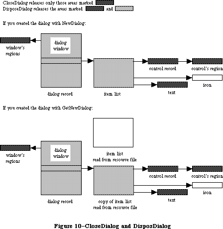 Figure 10–CloseDialog and DisposDialog
Call CloseDialog when you’re done with a dialog if you supplied NewDialog or GetNewDialog with a pointer to the dialog storage (in the dStorage parameter) when you created the dialog.
Note: Even if you didn’t supply a pointer to the dialog storage, you may
want to call CloseDialog if you created the dialog with NewDialog.
You would call CloseDialog if you wanted to keep the item list around
(since, unlike GetNewDialog, NewDialog does not use a copy of the
item list).
PROCEDURE DisposDialog (theDialog: DialogPtr);
DisposDialog calls CloseDialog (above) and then releases the memory occupied by the dialog’s item list and dialog record. Call DisposDialog when you’re done with a dialog if you let the dialog record be allocated in the heap when you created the dialog (by passing NIL as the dStorage parameter to NewDialog or GetNewDialog).
PROCEDURE CouldDialog (dialogID: INTEGER);
CouldDialog makes the dialog template having the given resource ID unpurgeable
(reading it into memory if it’s not already there). It does the same for the dialog window’s definition function, the dialog’s item list resource, and any items defined as resources. This is useful if the dialog box may come up when the resource file isn’t accessible, such as during a disk copy.
Warning: CouldDialog assumes your dialogs use the system font; if you’ve
changed the font with SetDAFont, calling CouldDialog doesn’t make
the font unpurgeable.
The CouldDialog procedure makes the dialog color table template unpurgeable
(reading it into memory if it isn’t already there), if it exists. It does the same for the dialog’s color item list, if it has one.
Warning: CouldDialog doesn’t load or make 'FONT' or 'FOND' resources
indicated in the color item list unpurgeable.
PROCEDURE FreeDialog (dialogID: INTEGER);
Given the resource ID of a dialog template previously specified in a call to CouldDialog, FreeDialog undoes the effect of CouldDialog (by making the resources purgeable). It should be called when there’s no longer a need to keep the resources in memory.
Given the resource ID of a dialog template previously specified in a call to CouldDialog, the FreeDialog routine undoes the effect of CouldDialog, by restoring the original purge state of the color table and color item list resources.
_______________________________________________________________________________
»Handling Dialog Events
PROCEDURE ModalDialog (filterProc: ProcPtr; VAR itemHit: INTEGER);
Call ModalDialog after creating a modal dialog and bringing up its window in the frontmost plane. ModalDialog repeatedly gets and handles events in the dialog’s window; after handling an event involving an enabled dialog item, it returns with the item number in itemHit. Normally you’ll then do whatever is appropriate as a response to an event in that item.
ModalDialog gets each event by calling the Toolbox Event Manager function GetNextEvent. If the event is a mouse-down event outside the content region of the dialog window, ModalDialog emits sound number 1 (which should be a single beep) and gets the next event; otherwise, it filters and handles the event as described below.
Note: Once before getting each event, ModalDialog calls SystemTask, a
Desk Manager procedure that must be called regularly so that desk
accessories will work properly.
The filterProc parameter determines how events are filtered. If it’s NIL, the standard filterProc function is executed; this causes ModalDialog to return 1 in itemHit if the Return key or Enter key is pressed. If filterProc isn’t NIL, ModalDialog filters events by executing the function it points to. Your filterProc function should have three parameters and return a Boolean value. For example, this is how it would be declared if it were named MyFilter:
FUNCTION MyFilter (theDialog: DialogPtr; VAR theEvent: EventRecord;
VAR itemHit: INTEGER) : BOOLEAN;
A function result of FALSE tells ModalDialog to go ahead and handle the event, which either can be sent through unchanged or can be changed to simulate a different event. A function result of TRUE tells ModalDialog to return immediately rather than handle the event; in this case, the filterProc function sets itemHit to the item number that ModalDialog should return.
Note: If you want it to be consistent with the standard filterProc function,
your function should at least check whether the Return key or Enter
key was pressed and, if so, return 1 in itemHit and a function result
of TRUE.
You can use the filterProc function, for example, to treat a typed character in a special way (such as ignore it, or make it have the same effect as another character or as clicking a button); in this case, the function would test for a key-down event with that character. As another example, suppose the dialog box contains a userItem whose procedure draws a clock with the current time displayed. The filterProc function can call that procedure and return FALSE without altering the current event.
Note: ModalDialog calls GetNextEvent with a mask that excludes disk-inserted
events. To receive disk-inserted events, your filterProc function can
call GetNextEvent (or EventAvail) with a mask that accepts only that
type of event.
ModalDialog handles the events for which the filterProc function returns FALSE as follows:
• In response to an activate or update event for the dialog window,
ModalDialog activates or updates the window.
• If the mouse button is pressed in an editText item, ModalDialog
responds to the mouse activity as appropriate (displaying an insertion
point or selecting text). If a key-down event occurs and there’s an
editText item, text entry and editing are handled in the standard way
for such items (except that if the Command key is down, ModalDialog
responds as though it’s not). In either case, ModalDialog returns if
the editText item is enabled or does nothing if it’s disabled. If a
key-down event occurs when there’s no editText item, ModalDialog does
nothing.
• If the mouse button is pressed in a control, ModalDialog calls the
Control Manager function TrackControl. If the mouse button is released
inside the control and the control is enabled, ModalDialog returns;
otherwise, it does nothing.
• If the mouse button is pressed in any other enabled item in the
dialog box, ModalDialog returns. If the mouse button is pressed in
any other disabled item or in no item, or if any other event occurs,
ModalDialog does nothing.
FUNCTION IsDialogEvent (theEvent: EventRecord) : BOOLEAN;
If your application includes any modeless dialogs, call IsDialogEvent after calling the Toolbox Event Manager function GetNextEvent.
Warning: If your modeless dialog contains any editText items, you must call
IsDialogEvent (and then DialogSelect) even if GetNextEvent returns
FALSE; otherwise your dialog won’t receive null events and the
caret won’t blink.
Pass the current event in theEvent. IsDialogEvent determines whether theEvent needs to be handled as part of a dialog. If theEvent is an activate or update event for a dialog window, a mouse-down event in the content region of an active dialog window, or any other type of event when a dialog window is active, IsDialogEvent returns TRUE; otherwise, it returns FALSE.
When FALSE is returned, just handle the event yourself like any other event that’s not dialog-related. When TRUE is returned, you’ll generally end up passing the event to DialogSelect for it to handle (as described below), but first you should do some additional checking:
• DialogSelect doesn’t handle keyboard equivalents of commands. Check
whether the event is a key-down event with the Command key held down
and, if so, carry out the command if it’s one that applies when a
dialog window is active. (If the command doesn’t so apply, do nothing.)
• In special cases, you may want to bypass DialogSelect or do some
preprocessing before calling it. If so, check for those events and
respond accordingly. You would need to do this, for example, if the
dialog is to respond to disk-inserted events.
For cases other than these, pass the event to DialogSelect for it to handle.
FUNCTION DialogSelect (theEvent: EventRecord; VAR theDialog: DialogPtr;
VAR itemHit: INTEGER) : BOOLEAN;
You’ll normally call DialogSelect when IsDialogEvent returns TRUE, passing in theEvent an event that needs to be handled as part of a modeless dialog. DialogSelect handles the event as described below. If the event involves an enabled dialog item, DialogSelect returns a function result of TRUE with the dialog pointer in theDialog and the item number in itemHit; otherwise, it returns FALSE with theDialog and itemHit undefined. Normally when DialogSelect returns TRUE, you’ll do whatever is appropriate as a response to the event, and when it returns FALSE you’ll do nothing.
If the event is an activate or update event for a dialog window, DialogSelect activates or updates the window and returns FALSE.
If the event is a mouse-down event in an editText item, DialogSelect responds as appropriate (displaying a caret at the insertion point or selecting text). If it’s a key-down or auto-key event and there’s an editText item, text entry and editing are handled in the standard way. In either case, DialogSelect returns TRUE if the editText item is enabled or FALSE if it’s disabled. If a key-down or auto-key event is passed when there’s no editText item, DialogSelect returns FALSE.
Note: For a keyboard event, DialogSelect doesn’t check to see whether the
Command key is held down; to handle keyboard equivalents of commands,
you have to check for them before calling DialogSelect. Similarly, to
treat a typed character in a special way (such as ignore it, or make
it have the same effect as another character or as clicking a button),
you need to check for a key-down event with that character before
calling DialogSelect.
If the event is a mouse-down event in a control, DialogSelect calls the Control Manager function TrackControl. If the mouse button is released inside the control and the control is enabled, DialogSelect returns TRUE; otherwise, it returns FALSE.
If the event is a mouse-down event in any other enabled item, DialogSelect returns TRUE. If it’s a mouse-down event in any other disabled item or in no item, or if it’s any other event, DialogSelect returns FALSE.
Note: If the event isn’t one that DialogSelect specifically checks for (if
it’s a null event, for example), and there’s an editText item in the
dialog, DialogSelect calls the TextEdit procedure TEIdle to make the
caret blink.
PROCEDURE DlgCut (theDialog: DialogPtr); [Not in ROM]
DlgCut checks whether theDialog has any editText items and, if so, applies the TextEdit procedure TECut to the currently selected editText item. (If the dialog record’s editField is 0 or greater, DlgCut passes the contents of the textH field to TECut.) You can call DlgCut to handle the editing command Cut when a modeless dialog window is active.
Assembly-language note: Assembly-language programmers can just read the
dialog record’s fields and call TextEdit directly.
PROCEDURE DlgCopy (theDialog: DialogPtr); [Not in ROM]
DlgCopy is the same as DlgCut (above) except that it calls TECopy, for handling the Copy command.
PROCEDURE DlgPaste (theDialog: DialogPtr); [Not in ROM]
DlgPaste is the same as DlgCut (above) except that it calls TEPaste, for handling the Paste command.
PROCEDURE DlgDelete (theDialog: DialogPtr); [Not in ROM]
DlgDelete is the same as DlgCut (above) except that it calls TEDelete, for handling the Clear command.
PROCEDURE DrawDialog (theDialog: DialogPtr);
DrawDialog draws the contents of the given dialog box. Since DialogSelect and ModalDialog handle dialog window updating, this procedure is useful only in unusual situations. You would call it, for example, to display a dialog box that doesn’t require any response but merely tells the user what’s going on during a time-consuming process.
PROCEDURE UpdtDialog (theDialog: DialogPtr; updateRgn: RgnHandle);
UpdtDialog is a faster version of the DrawDialog procedure. Instead of drawing the entire contents of the given dialog box, UpdtDialog draws only the items that are in a specified update region. UpdtDialog is called in response to an update event, and is usually bracketed by calls to the Window Manager procedures BeginUpdate and EndUpdate. UpdateRgn should be set to the visRgn of theWindow’s port. (For more details, see the BeginUpdate procedure in the Window Manager chapter.)
_______________________________________________________________________________
»Invoking Alerts
FUNCTION Alert (alertID: INTEGER; filterProc: ProcPtr) : INTEGER;
This function invokes the alert defined by the alert template that has the given resource ID. It calls the current sound procedure, if any, passing it the sound number specified in the alert template for this stage of the alert. If no alert box is to be drawn at this stage, Alert returns a function result of –1; otherwise, it creates and displays the alert window for this alert and draws the alert box.
Warning: If the alert template resource can’t be read, the function result
is undefined.
Note: Alert creates the alert window by calling NewDialog, and does the
rest of its processing by calling ModalDialog.
Alert repeatedly gets and handles events in the alert window until an enabled item is clicked, at which time it returns the item number. Normally you’ll then do whatever is appropriate in response to a click of that item.
Alert gets each event by calling the Toolbox Event Manager function GetNextEvent. If the event is a mouse-down event outside the content region of the alert window, Alert emits sound number 1 (which should be a single beep) and gets the next event; otherwise, it filters and handles the event as described below.
The filterProc parameter has the same meaning as in ModalDialog (see above). If it’s NIL, the standard filterProc function is executed, which makes the Return key or the Enter key have the same effect as clicking the default button. If you specify your own filterProc function and want to retain this feature, you must include it in your function. You can find out what the current default button is by looking at the aDefItem field of the dialog record for the alert
(via the dialog pointer passed to the function).
Alert handles the events for which the filterProc function returns FALSE as follows:
• If the mouse button is pressed in a control, Alert calls the Control
Manager procedure TrackControl. If the mouse button is released inside
the control and the control is enabled, Alert returns; otherwise, it
does nothing.
• If the mouse button is pressed in any other enabled item, Alert simply
returns. If it’s pressed in any other disabled item or in no item, or
if any other event occurs, Alert does nothing.
Before returning to the application with the item number, Alert removes the alert box from the screen. (It disposes of the alert window and its associated data structures, the item list, and the items.)
Note: When an alert is removed, if it was overlapping the default button
of a previous alert, that button’s bold outline won’t be redrawn.
Note: The Alert function’s removal of the alert box would not be the
desired result if the user clicked a check box or radio button;
however, normally alerts contain only static text, icons, pictures,
and buttons that are supposed to make the alert box go away. If your
alert contains other items besides these, consider whether it might
be more appropriate as a dialog.
The Alert function looks for a resource of type 'actb' with the same ID as the alert. The alert color table is copied before it is passed to SetWinSize unless its ctSize field is equal to –1, indicating that the default window colors are to be used instead. The copy is made so that the color table resource can be purged without affecting the alert.
The color dialog item list resource is duplicated as well, so it can be purgeable.
FUNCTION StopAlert (alertID: INTEGER; filterProc: ProcPtr) : INTEGER;
StopAlert is the same as the Alert function (above) except that before drawing the items of the alert in the alert box, it draws the Stop icon in the top left corner of the box (within the rectangle (10,20)(42,52)). The Stop icon has the following resource ID:
CONST stopIcon = 0;
If the application’s resource file doesn’t include an icon with that ID number, the Dialog Manager uses the standard Stop icon in the system resource file (see Figure 11).
The calls CautionAlert, StopAlert, and NoteAlert look for a resource of type
'actb' with the same ID as the alert.
Figure 10–CloseDialog and DisposDialog
Call CloseDialog when you’re done with a dialog if you supplied NewDialog or GetNewDialog with a pointer to the dialog storage (in the dStorage parameter) when you created the dialog.
Note: Even if you didn’t supply a pointer to the dialog storage, you may
want to call CloseDialog if you created the dialog with NewDialog.
You would call CloseDialog if you wanted to keep the item list around
(since, unlike GetNewDialog, NewDialog does not use a copy of the
item list).
PROCEDURE DisposDialog (theDialog: DialogPtr);
DisposDialog calls CloseDialog (above) and then releases the memory occupied by the dialog’s item list and dialog record. Call DisposDialog when you’re done with a dialog if you let the dialog record be allocated in the heap when you created the dialog (by passing NIL as the dStorage parameter to NewDialog or GetNewDialog).
PROCEDURE CouldDialog (dialogID: INTEGER);
CouldDialog makes the dialog template having the given resource ID unpurgeable
(reading it into memory if it’s not already there). It does the same for the dialog window’s definition function, the dialog’s item list resource, and any items defined as resources. This is useful if the dialog box may come up when the resource file isn’t accessible, such as during a disk copy.
Warning: CouldDialog assumes your dialogs use the system font; if you’ve
changed the font with SetDAFont, calling CouldDialog doesn’t make
the font unpurgeable.
The CouldDialog procedure makes the dialog color table template unpurgeable
(reading it into memory if it isn’t already there), if it exists. It does the same for the dialog’s color item list, if it has one.
Warning: CouldDialog doesn’t load or make 'FONT' or 'FOND' resources
indicated in the color item list unpurgeable.
PROCEDURE FreeDialog (dialogID: INTEGER);
Given the resource ID of a dialog template previously specified in a call to CouldDialog, FreeDialog undoes the effect of CouldDialog (by making the resources purgeable). It should be called when there’s no longer a need to keep the resources in memory.
Given the resource ID of a dialog template previously specified in a call to CouldDialog, the FreeDialog routine undoes the effect of CouldDialog, by restoring the original purge state of the color table and color item list resources.
_______________________________________________________________________________
»Handling Dialog Events
PROCEDURE ModalDialog (filterProc: ProcPtr; VAR itemHit: INTEGER);
Call ModalDialog after creating a modal dialog and bringing up its window in the frontmost plane. ModalDialog repeatedly gets and handles events in the dialog’s window; after handling an event involving an enabled dialog item, it returns with the item number in itemHit. Normally you’ll then do whatever is appropriate as a response to an event in that item.
ModalDialog gets each event by calling the Toolbox Event Manager function GetNextEvent. If the event is a mouse-down event outside the content region of the dialog window, ModalDialog emits sound number 1 (which should be a single beep) and gets the next event; otherwise, it filters and handles the event as described below.
Note: Once before getting each event, ModalDialog calls SystemTask, a
Desk Manager procedure that must be called regularly so that desk
accessories will work properly.
The filterProc parameter determines how events are filtered. If it’s NIL, the standard filterProc function is executed; this causes ModalDialog to return 1 in itemHit if the Return key or Enter key is pressed. If filterProc isn’t NIL, ModalDialog filters events by executing the function it points to. Your filterProc function should have three parameters and return a Boolean value. For example, this is how it would be declared if it were named MyFilter:
FUNCTION MyFilter (theDialog: DialogPtr; VAR theEvent: EventRecord;
VAR itemHit: INTEGER) : BOOLEAN;
A function result of FALSE tells ModalDialog to go ahead and handle the event, which either can be sent through unchanged or can be changed to simulate a different event. A function result of TRUE tells ModalDialog to return immediately rather than handle the event; in this case, the filterProc function sets itemHit to the item number that ModalDialog should return.
Note: If you want it to be consistent with the standard filterProc function,
your function should at least check whether the Return key or Enter
key was pressed and, if so, return 1 in itemHit and a function result
of TRUE.
You can use the filterProc function, for example, to treat a typed character in a special way (such as ignore it, or make it have the same effect as another character or as clicking a button); in this case, the function would test for a key-down event with that character. As another example, suppose the dialog box contains a userItem whose procedure draws a clock with the current time displayed. The filterProc function can call that procedure and return FALSE without altering the current event.
Note: ModalDialog calls GetNextEvent with a mask that excludes disk-inserted
events. To receive disk-inserted events, your filterProc function can
call GetNextEvent (or EventAvail) with a mask that accepts only that
type of event.
ModalDialog handles the events for which the filterProc function returns FALSE as follows:
• In response to an activate or update event for the dialog window,
ModalDialog activates or updates the window.
• If the mouse button is pressed in an editText item, ModalDialog
responds to the mouse activity as appropriate (displaying an insertion
point or selecting text). If a key-down event occurs and there’s an
editText item, text entry and editing are handled in the standard way
for such items (except that if the Command key is down, ModalDialog
responds as though it’s not). In either case, ModalDialog returns if
the editText item is enabled or does nothing if it’s disabled. If a
key-down event occurs when there’s no editText item, ModalDialog does
nothing.
• If the mouse button is pressed in a control, ModalDialog calls the
Control Manager function TrackControl. If the mouse button is released
inside the control and the control is enabled, ModalDialog returns;
otherwise, it does nothing.
• If the mouse button is pressed in any other enabled item in the
dialog box, ModalDialog returns. If the mouse button is pressed in
any other disabled item or in no item, or if any other event occurs,
ModalDialog does nothing.
FUNCTION IsDialogEvent (theEvent: EventRecord) : BOOLEAN;
If your application includes any modeless dialogs, call IsDialogEvent after calling the Toolbox Event Manager function GetNextEvent.
Warning: If your modeless dialog contains any editText items, you must call
IsDialogEvent (and then DialogSelect) even if GetNextEvent returns
FALSE; otherwise your dialog won’t receive null events and the
caret won’t blink.
Pass the current event in theEvent. IsDialogEvent determines whether theEvent needs to be handled as part of a dialog. If theEvent is an activate or update event for a dialog window, a mouse-down event in the content region of an active dialog window, or any other type of event when a dialog window is active, IsDialogEvent returns TRUE; otherwise, it returns FALSE.
When FALSE is returned, just handle the event yourself like any other event that’s not dialog-related. When TRUE is returned, you’ll generally end up passing the event to DialogSelect for it to handle (as described below), but first you should do some additional checking:
• DialogSelect doesn’t handle keyboard equivalents of commands. Check
whether the event is a key-down event with the Command key held down
and, if so, carry out the command if it’s one that applies when a
dialog window is active. (If the command doesn’t so apply, do nothing.)
• In special cases, you may want to bypass DialogSelect or do some
preprocessing before calling it. If so, check for those events and
respond accordingly. You would need to do this, for example, if the
dialog is to respond to disk-inserted events.
For cases other than these, pass the event to DialogSelect for it to handle.
FUNCTION DialogSelect (theEvent: EventRecord; VAR theDialog: DialogPtr;
VAR itemHit: INTEGER) : BOOLEAN;
You’ll normally call DialogSelect when IsDialogEvent returns TRUE, passing in theEvent an event that needs to be handled as part of a modeless dialog. DialogSelect handles the event as described below. If the event involves an enabled dialog item, DialogSelect returns a function result of TRUE with the dialog pointer in theDialog and the item number in itemHit; otherwise, it returns FALSE with theDialog and itemHit undefined. Normally when DialogSelect returns TRUE, you’ll do whatever is appropriate as a response to the event, and when it returns FALSE you’ll do nothing.
If the event is an activate or update event for a dialog window, DialogSelect activates or updates the window and returns FALSE.
If the event is a mouse-down event in an editText item, DialogSelect responds as appropriate (displaying a caret at the insertion point or selecting text). If it’s a key-down or auto-key event and there’s an editText item, text entry and editing are handled in the standard way. In either case, DialogSelect returns TRUE if the editText item is enabled or FALSE if it’s disabled. If a key-down or auto-key event is passed when there’s no editText item, DialogSelect returns FALSE.
Note: For a keyboard event, DialogSelect doesn’t check to see whether the
Command key is held down; to handle keyboard equivalents of commands,
you have to check for them before calling DialogSelect. Similarly, to
treat a typed character in a special way (such as ignore it, or make
it have the same effect as another character or as clicking a button),
you need to check for a key-down event with that character before
calling DialogSelect.
If the event is a mouse-down event in a control, DialogSelect calls the Control Manager function TrackControl. If the mouse button is released inside the control and the control is enabled, DialogSelect returns TRUE; otherwise, it returns FALSE.
If the event is a mouse-down event in any other enabled item, DialogSelect returns TRUE. If it’s a mouse-down event in any other disabled item or in no item, or if it’s any other event, DialogSelect returns FALSE.
Note: If the event isn’t one that DialogSelect specifically checks for (if
it’s a null event, for example), and there’s an editText item in the
dialog, DialogSelect calls the TextEdit procedure TEIdle to make the
caret blink.
PROCEDURE DlgCut (theDialog: DialogPtr); [Not in ROM]
DlgCut checks whether theDialog has any editText items and, if so, applies the TextEdit procedure TECut to the currently selected editText item. (If the dialog record’s editField is 0 or greater, DlgCut passes the contents of the textH field to TECut.) You can call DlgCut to handle the editing command Cut when a modeless dialog window is active.
Assembly-language note: Assembly-language programmers can just read the
dialog record’s fields and call TextEdit directly.
PROCEDURE DlgCopy (theDialog: DialogPtr); [Not in ROM]
DlgCopy is the same as DlgCut (above) except that it calls TECopy, for handling the Copy command.
PROCEDURE DlgPaste (theDialog: DialogPtr); [Not in ROM]
DlgPaste is the same as DlgCut (above) except that it calls TEPaste, for handling the Paste command.
PROCEDURE DlgDelete (theDialog: DialogPtr); [Not in ROM]
DlgDelete is the same as DlgCut (above) except that it calls TEDelete, for handling the Clear command.
PROCEDURE DrawDialog (theDialog: DialogPtr);
DrawDialog draws the contents of the given dialog box. Since DialogSelect and ModalDialog handle dialog window updating, this procedure is useful only in unusual situations. You would call it, for example, to display a dialog box that doesn’t require any response but merely tells the user what’s going on during a time-consuming process.
PROCEDURE UpdtDialog (theDialog: DialogPtr; updateRgn: RgnHandle);
UpdtDialog is a faster version of the DrawDialog procedure. Instead of drawing the entire contents of the given dialog box, UpdtDialog draws only the items that are in a specified update region. UpdtDialog is called in response to an update event, and is usually bracketed by calls to the Window Manager procedures BeginUpdate and EndUpdate. UpdateRgn should be set to the visRgn of theWindow’s port. (For more details, see the BeginUpdate procedure in the Window Manager chapter.)
_______________________________________________________________________________
»Invoking Alerts
FUNCTION Alert (alertID: INTEGER; filterProc: ProcPtr) : INTEGER;
This function invokes the alert defined by the alert template that has the given resource ID. It calls the current sound procedure, if any, passing it the sound number specified in the alert template for this stage of the alert. If no alert box is to be drawn at this stage, Alert returns a function result of –1; otherwise, it creates and displays the alert window for this alert and draws the alert box.
Warning: If the alert template resource can’t be read, the function result
is undefined.
Note: Alert creates the alert window by calling NewDialog, and does the
rest of its processing by calling ModalDialog.
Alert repeatedly gets and handles events in the alert window until an enabled item is clicked, at which time it returns the item number. Normally you’ll then do whatever is appropriate in response to a click of that item.
Alert gets each event by calling the Toolbox Event Manager function GetNextEvent. If the event is a mouse-down event outside the content region of the alert window, Alert emits sound number 1 (which should be a single beep) and gets the next event; otherwise, it filters and handles the event as described below.
The filterProc parameter has the same meaning as in ModalDialog (see above). If it’s NIL, the standard filterProc function is executed, which makes the Return key or the Enter key have the same effect as clicking the default button. If you specify your own filterProc function and want to retain this feature, you must include it in your function. You can find out what the current default button is by looking at the aDefItem field of the dialog record for the alert
(via the dialog pointer passed to the function).
Alert handles the events for which the filterProc function returns FALSE as follows:
• If the mouse button is pressed in a control, Alert calls the Control
Manager procedure TrackControl. If the mouse button is released inside
the control and the control is enabled, Alert returns; otherwise, it
does nothing.
• If the mouse button is pressed in any other enabled item, Alert simply
returns. If it’s pressed in any other disabled item or in no item, or
if any other event occurs, Alert does nothing.
Before returning to the application with the item number, Alert removes the alert box from the screen. (It disposes of the alert window and its associated data structures, the item list, and the items.)
Note: When an alert is removed, if it was overlapping the default button
of a previous alert, that button’s bold outline won’t be redrawn.
Note: The Alert function’s removal of the alert box would not be the
desired result if the user clicked a check box or radio button;
however, normally alerts contain only static text, icons, pictures,
and buttons that are supposed to make the alert box go away. If your
alert contains other items besides these, consider whether it might
be more appropriate as a dialog.
The Alert function looks for a resource of type 'actb' with the same ID as the alert. The alert color table is copied before it is passed to SetWinSize unless its ctSize field is equal to –1, indicating that the default window colors are to be used instead. The copy is made so that the color table resource can be purged without affecting the alert.
The color dialog item list resource is duplicated as well, so it can be purgeable.
FUNCTION StopAlert (alertID: INTEGER; filterProc: ProcPtr) : INTEGER;
StopAlert is the same as the Alert function (above) except that before drawing the items of the alert in the alert box, it draws the Stop icon in the top left corner of the box (within the rectangle (10,20)(42,52)). The Stop icon has the following resource ID:
CONST stopIcon = 0;
If the application’s resource file doesn’t include an icon with that ID number, the Dialog Manager uses the standard Stop icon in the system resource file (see Figure 11).
The calls CautionAlert, StopAlert, and NoteAlert look for a resource of type
'actb' with the same ID as the alert.
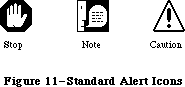 Figure 11–Standard Alert Icons
FUNCTION NoteAlert (alertID: INTEGER; filterProc: ProcPtr) : INTEGER;
NoteAlert is like StopAlert except that it draws the Note icon, which has the following resource ID:
CONST noteIcon = 1;
The calls CautionAlert, StopAlert, and NoteAlert look for a resource of type
'actb' with the same ID as the alert.
FUNCTION CautionAlert (alertID: INTEGER; filterProc: ProcPtr) : INTEGER;
CautionAlert is like StopAlert except that it draws the Caution icon, which has the following resource ID:
CONST cautionIcon = 2;
The calls CautionAlert, StopAlert, and NoteAlert look for a resource of type
'actb' with the same ID as the alert.
PROCEDURE CouldAlert (alertID: INTEGER);
CouldAlert makes the alert template having the given resource ID unpurgeable
(reading it into memory if it’s not already there). It does the same for the alert window’s definition function, the alert’s item list resource, and any items defined as resources. This is useful if the alert may occur when the resource file isn’t accessible, such as during a disk copy.
Warning: Like CouldDialog, CouldAlert assumes your alerts use the system
font; if you’ve changed the font with SetDAFont, calling CouldAlert
doesn’t make the font unpurgeable.
The CouldAlert routine makes the alert color table template unpurgeable
(reading it into memory if it isn’t already there), if it exists. It does the same for the alert’s color item list, if it has one.
Warning: Like CouldDialog, CouldAlert doesn’t load or make 'FONT' or
'FOND' resources indicated in the color item list unpurgeable.
PROCEDURE FreeAlert (alertID: INTEGER);
Given the resource ID of an alert template previously specified in a call to CouldAlert, FreeAlert undoes the effect of CouldAlert (by making the resources purgeable). It should be called when there’s no longer a need to keep the resources in memory.
Given the resource ID of an alert template previously specified in a call to CouldAlert, the FreeAlert routine undoes the effect of CouldAlert, by restoring the original purge state of the color table and color item list resources.
_______________________________________________________________________________
»Manipulating Items in Dialogs and Alerts
PROCEDURE ParamText (param0,param1,param2,param3: Str255);
ParamText provides a means of substituting text in statText items: param0 through param3 will replace the special strings '^0' through '^3' in all statText items in all subsequent dialog or alert boxes. Pass empty strings for parameters not used.
Assembly-language note: Assembly-language programmers may pass NIL for
parameters not used or for strings that are not
to be changed.
For example, if the text is defined as 'Cannot open document ^0' and docName is a string variable containing a document name that the user typed, you can call ParamText(docName,' ',' ',' ')
Note: All strings that may need to be translated to other languages should
be stored in resource files.
Assembly-language note: The Dialog Manager stores handles to the four
ParamText parameters in a global array named DAStrings.
PROCEDURE GetDItem (theDialog: DialogPtr; itemNo: INTEGER;
VAR itemType: INTEGER; VAR item: Handle; VAR box: Rect);
GetDItem returns in its VAR parameters the following information about the item numbered itemNo in the given dialog’s item list: In the itemType parameter, the item type; in the item parameter, a handle to the item (or, for item type userItem, the procedure pointer); and in the box parameter, the display rectangle for the item.
Suppose, for example, that you want to change the title of a control in a dialog box. You can get the item handle with GetDItem, coerce it to type ControlHandle, and call the Control Manager procedure SetCTitle to change the title. Similarly, to move the control or change its size, you would call MoveControl or SizeControl.
Note: To access the text of a statText or editText item, you can pass the
handle returned by GetDItem to GetIText or SetIText (see below).
PROCEDURE SetDItem (theDialog: DialogPtr; itemNo: INTEGER; itemType: INTEGER;
item: Handle; box: Rect);
SetDItem sets the item numbered itemNo in the given dialog’s item list, as specified by the parameters (without drawing the item). The itemType parameter is the item type; the item parameter is a handle to the item (or, for item type userItem, the procedure pointer); and the box parameter is the display rectangle for the item.
Consider, for example, how to install an item of type userItem in a dialog: In the item list in the resource file, define an item in which the type is set to userItem and the display rectangle to (0,0)(0,0). Specify that the dialog window be invisible (in either the dialog template or the NewDialog call). After creating the dialog, coerce the item’s procedure pointer to type Handle; then call SetDItem, passing that handle and the display rectangle for the item. Finally, call the Window Manager procedure ShowWindow to display the dialog window.
Note: Do not use SetDItem to change the text of a statText or editText item
or to change or move a control. See the description of GetDItem above
for more information.
PROCEDURE HideDItem (theDialog: DialogPtr; itemNo: INTEGER);
HideDItem hides the item numbered itemNo in the given dialog’s item list by giving the item a display rectangle that’s off the screen. (Specifically, if the left coordinate of the item’s display rectangle is less than 8192, ShowDItem adds 16384 to both the left and right coordinates the rectangle.) If the item is already hidden (that is, if the left coordinate is greater than 8192), HideDItem does nothing.
HideDItem calls the EraseRect procedure on the item’s enclosing rectangle and adds the rectangle that contained the item (not necessarily the item’s display rectangle) to the update region. If the specified item is an active editText item, the item is first deactivated (by calling TEDeactivate).
Note: If you have items that are close to each other, be aware that the
Dialog Manager draws outside of the enclosing rectangle by 3 pixels
for editText items and by 4 pixels for a default button.
An item that’s been hidden by HideDItem can be redisplayed by the ShowDItem procedure.
Note: To create a hidden item in a dialog item list, simply add 16384 to
the left and right coordinates of the display rectangle.
PROCEDURE ShowDItem (theDialog: DialogPtr; itemNo: INTEGER);
ShowDItem redisplays the item numbered itemNo, previously hidden by HideDItem, by giving the item the display rectangle it had prior to the HideDItem call.
(Specifically, if the left coordinate of the item’s display rectangle is greater than 8192, ShowDItem subtracts 16384 from both the left and right coordinates the rectangle.) If the item is already visible (that is, if the left coordinate is less than 8192), ShowDItem does nothing.
ShowDItem adds the rectangle that contained the item (not necessarily the
item’s display rectangle) to the update region so that it will be drawn. If the item becomes the only editText item, ShowDItem activates it (by calling TEActivate).
FUNCTION FindDItem (theDialog: DialogPtr; thePt: Point) : INTEGER;
FindDItem returns the item number of the item containing the point specified, in local coordinates, by thePt. If the point doesn’t lie within the item’s rectangle, FindDItem returns –1. If there are overlapping items, it returns the item number of the first item in the list containing the point. FindDItem is useful for changing the cursor when it’s over a particular item.
Note: FindDItem will return the item number of disabled items as well.
PROCEDURE GetIText (item: Handle; VAR text: Str255);
Given a handle to a statText or editText item in a dialog box, as returned by GetDItem, GetIText returns the text of the item in the text parameter. (If the user typed more than 255 characters in an editText item, GetIText returns only the first 255.)
PROCEDURE SetIText (item: Handle; text: Str255);
Given a handle to a statText or editText item in a dialog box, as returned by GetDItem, SetIText sets the text of the item to the specified text and draws the item. For example, suppose the exact content of a dialog’s text item cannot be determined until the application is running, but the display rectangle is defined in the resource file: Call GetDItem to get a handle to the item, and call SetIText with the desired text.
PROCEDURE SelIText (theDialog: DialogPtr; itemNo: INTEGER;
strtSel,endSel: INTEGER)
Given a pointer to a dialog and the item number of an editText item in the dialog box, SelIText does the following:
• If the item contains text, SelIText sets the selection range to extend
from character position strtSel up to but not including character
position endSel. The selection range is inverted unless strtSel equals
endSel, in which case a blinking vertical bar is displayed to indicate
an insertion point at that position.
• If the item doesn’t contain text, SelIText simply displays the insertion
point.
For example, if the user makes an unacceptable entry in the editText item, the application can put up an alert box reporting the problem and then select the entire text of the item so it can be replaced by a new entry. (Without this procedure, the user would have to select the item before making the new entry.)
Note: You can select the entire texxt by specifying 0 for strtSel and 32767
for endSel. For details about selection range and character position,
see the TextEdit chapter.
FUNCTION GetAlrtStage : INTEGER; [Not in ROM]
GetAlrtStage returns the stage of the last occurrence of an alert, as a number from 0 to 3.
Assembly-language note: Assembly-language programmers can get this number
by accessing the global variable ACount. In addition,
the global variable ANumber contains the resource ID
of the alert template of the last alert that occurred.
PROCEDURE ResetAlrtStage; [Not in ROM]
ResetAlrtStage resets the stage of the last occurrence of an alert so that the next occurrence of that same alert will be treated as its first stage. This is useful, for example, when you’ve used ParamText to change the text of an alert such that from the user’s point of view it’s a different alert.
Assembly-language note: Assembly-language programmers can set the global
variable ACount to –1 for the same effect.
_______________________________________________________________________________
»MODIFYING TEMPLATES IN MEMORY
_______________________________________________________________________________
When you call GetNewDialog or one of the routines that invokes an alert, the Dialog Manager calls the Resource Manager to read the dialog or alert template from the resource file and return a handle to it. If the template is already in memory, the Resource Manager just returns a handle to it. If you want, you can call the Resource Manager yourself to read the template into memory (and make it unpurgeable), and then make changes to it before calling the dialog or alert routine. When called by the Dialog Manager, the Resource Manager will return a handle to the template as you modified it.
To modify a template in memory, you need to know its exact structure and the data type of the handle through which it may be accessed. These are discussed below for dialogs and alerts.
_______________________________________________________________________________
»Dialog Templates in Memory
The data structure of a dialog template is as follows:
TYPE DialogTemplate = RECORD
boundsRect: Rect; {becomes window's portRect}
procID: INTEGER; {window definiton ID}
visible: BOOLEAN; {TRUE if visible}
filler1: BOOLEAN; {not used}
goAwayFlag: BOOLEAN; {TRUE if has go-away region}
filler2: BOOLEAN; {not used}
refCon: LONGINT; {window's reference value}
itemsID: INTEGER; {resource ID of item list}
title: Str255 {window's title}
END;
The filler1 and filler2 fields are there because for historical reasons the goAwayFlag and refCon fields have to begin on a word boundary. The itemsID field contains the resource ID of the dialog’s item list. The other fields are the same as the parameters of the same name in the NewDialog function; they provide information about the dialog window.
You access the dialog template by converting the handle returned by the Resource Manager to a template handle:
TYPE DialogTHndl = ^DialogTPtr;
DialogTPtr = ^DialogTemplate;
_______________________________________________________________________________
»Alert Templates in Memory
The data structure of an alert template is as follows:
TYPE AlertTemplate = RECORD
boundsRect: Rect; {becomes window's portRect}
itemsID: INTEGER; {resource ID of item list}
stages: StageList {alert stage information}
END;
BoundsRect is the rectangle that becomes the portRect of the window's grafPort. The itemsID field contains the resource ID of the item list for the alert.
The information in the stages field determines exactly what should happen at each stage of the alert. It's packed into a word that has the following structure:
TYPE StageList = PACKED RECORD
boldItm4: 0..1; {default button item number minus 1}
boxDrwn4: BOOLEAN; {TRUE if alert box to be drawn}
sound4: 0..3 {sound number}
boldItm3: 0..1;
boxDrwn3: BOOLEAN;
sound3: 0..3
boldItm2: 0..1;
boxDrwn2: BOOLEAN;
sound2: 0..3
boldItm1: 0..1;
boxDrwn1: BOOLEAN;
sound1: 0..3
END;
Notice that the information is stored in reverse order—for the fourth stage first, and for the first stage last.
The boldItm field indicates which button should be the default button (and therefore boldly outlined in the alert box). If the first two items in the alert’s item list are the OK button and the Cancel button, respectively, 0 will refer to the OK button and 1 to the Cancel button. The reason for this is that the value of boldItm plus 1 is interpreted as an item number, and normally items 1 and 2 are the OK and Cancel buttons, respectively. Whatever the item having the corresponding item number happens to be, a bold rounded-corner rectangle will be drawn outside its display rectangle.
Note: When deciding where to place items in an alert box, be sure to allow
room for any bold outlines that may be drawn.
The boxDrwn field is TRUE if the alert box is to be drawn.
The sound field specifies which sound should be emitted at this stage of the alert, with a number from 0 to 3 that’s passed to the current sound procedure. You can call ErrorSound to specify your own sound procedure; if you don’t, the standard sound procedure will be used (as described earlier in the “Alerts” section).
You access the alert template by converting the handle returned by the Resource Manager to a template handle:
TYPE AlertTHndl = ^AlertTPtr;
AlertTPtr = ^AlertTemplate;
Assembly-language note: Rather than offsets into the fields of the StageList
data structure, there are masks for accessing the
information stored for an alert stage in a stages
word; they’re listed in the summary at the end of
this chapter.
_______________________________________________________________________________
»FORMATS OF RESOURCES FOR DIALOGS AND ALERTS
_______________________________________________________________________________
Every dialog template, alert template, and item list must be stored in a resource file, as must any icons or QuickDraw pictures in item lists and any control templates for items of type ctrlItem+resCtrl. The exact formats of a dialog template, alert template, and item list in a resource file are given below. For icons and pictures, the resource type is 'ICON' or 'PICT' and the resource data is simply the icon or the picture. The format of a control template is discussed in the Control Manager chapter.
_______________________________________________________________________________
»Dialog Templates in a Resource File
The resource type for a dialog template is 'DLOG', and the resource data has the same format as a dialog template in memory.
Number of bytes Contents
8 bytes Same as boundsRect parameter to NewDialog
2 bytes Same as procID parameter to NewDialog
1 byte Same as visible parameter to NewDialog
1 byte Ignored
1 byte Same as goAwayFlag parameter to NewDialog
1 byte Ignored
4 bytes Same as refCon parameter to NewDialog
2 bytes Resource ID of item list
n bytes Same as title parameter to NewDialog
(1-byte length in bytes, followed by the characters
of the title)
_______________________________________________________________________________
»Alert Templates in a Resource File
The resource type for an alert template is 'ALRT', and the resource data has the same format as an alert template in memory.
Number of bytes Contents
8 bytes Rectangle enclosing alert window
2 bytes Resource ID of item list
2 bytes Four stages
The resource data ends with a word of information about stages. As shown in the example in Figure 12, there are four bits of stage information for each of the four stages, from the four low-order bits for the first stage to the four high-order bits for the fourth stage. Each set of four bits is as follows:
Number of bits Contents
1 bit Item number minus 1 of default button; normally 0
is OK and 1 is Cancel
1 bit 1 if alert box is to be drawn, 0 if not
2 bits Sound number (0 through 3)
Note: So that the disk won’t be accessed just for an alert that beeps,
you may want to set the resPreload attribute of the alert’s template
in the resource file. For more information, see the Resource Manager
chapter.
Figure 11–Standard Alert Icons
FUNCTION NoteAlert (alertID: INTEGER; filterProc: ProcPtr) : INTEGER;
NoteAlert is like StopAlert except that it draws the Note icon, which has the following resource ID:
CONST noteIcon = 1;
The calls CautionAlert, StopAlert, and NoteAlert look for a resource of type
'actb' with the same ID as the alert.
FUNCTION CautionAlert (alertID: INTEGER; filterProc: ProcPtr) : INTEGER;
CautionAlert is like StopAlert except that it draws the Caution icon, which has the following resource ID:
CONST cautionIcon = 2;
The calls CautionAlert, StopAlert, and NoteAlert look for a resource of type
'actb' with the same ID as the alert.
PROCEDURE CouldAlert (alertID: INTEGER);
CouldAlert makes the alert template having the given resource ID unpurgeable
(reading it into memory if it’s not already there). It does the same for the alert window’s definition function, the alert’s item list resource, and any items defined as resources. This is useful if the alert may occur when the resource file isn’t accessible, such as during a disk copy.
Warning: Like CouldDialog, CouldAlert assumes your alerts use the system
font; if you’ve changed the font with SetDAFont, calling CouldAlert
doesn’t make the font unpurgeable.
The CouldAlert routine makes the alert color table template unpurgeable
(reading it into memory if it isn’t already there), if it exists. It does the same for the alert’s color item list, if it has one.
Warning: Like CouldDialog, CouldAlert doesn’t load or make 'FONT' or
'FOND' resources indicated in the color item list unpurgeable.
PROCEDURE FreeAlert (alertID: INTEGER);
Given the resource ID of an alert template previously specified in a call to CouldAlert, FreeAlert undoes the effect of CouldAlert (by making the resources purgeable). It should be called when there’s no longer a need to keep the resources in memory.
Given the resource ID of an alert template previously specified in a call to CouldAlert, the FreeAlert routine undoes the effect of CouldAlert, by restoring the original purge state of the color table and color item list resources.
_______________________________________________________________________________
»Manipulating Items in Dialogs and Alerts
PROCEDURE ParamText (param0,param1,param2,param3: Str255);
ParamText provides a means of substituting text in statText items: param0 through param3 will replace the special strings '^0' through '^3' in all statText items in all subsequent dialog or alert boxes. Pass empty strings for parameters not used.
Assembly-language note: Assembly-language programmers may pass NIL for
parameters not used or for strings that are not
to be changed.
For example, if the text is defined as 'Cannot open document ^0' and docName is a string variable containing a document name that the user typed, you can call ParamText(docName,' ',' ',' ')
Note: All strings that may need to be translated to other languages should
be stored in resource files.
Assembly-language note: The Dialog Manager stores handles to the four
ParamText parameters in a global array named DAStrings.
PROCEDURE GetDItem (theDialog: DialogPtr; itemNo: INTEGER;
VAR itemType: INTEGER; VAR item: Handle; VAR box: Rect);
GetDItem returns in its VAR parameters the following information about the item numbered itemNo in the given dialog’s item list: In the itemType parameter, the item type; in the item parameter, a handle to the item (or, for item type userItem, the procedure pointer); and in the box parameter, the display rectangle for the item.
Suppose, for example, that you want to change the title of a control in a dialog box. You can get the item handle with GetDItem, coerce it to type ControlHandle, and call the Control Manager procedure SetCTitle to change the title. Similarly, to move the control or change its size, you would call MoveControl or SizeControl.
Note: To access the text of a statText or editText item, you can pass the
handle returned by GetDItem to GetIText or SetIText (see below).
PROCEDURE SetDItem (theDialog: DialogPtr; itemNo: INTEGER; itemType: INTEGER;
item: Handle; box: Rect);
SetDItem sets the item numbered itemNo in the given dialog’s item list, as specified by the parameters (without drawing the item). The itemType parameter is the item type; the item parameter is a handle to the item (or, for item type userItem, the procedure pointer); and the box parameter is the display rectangle for the item.
Consider, for example, how to install an item of type userItem in a dialog: In the item list in the resource file, define an item in which the type is set to userItem and the display rectangle to (0,0)(0,0). Specify that the dialog window be invisible (in either the dialog template or the NewDialog call). After creating the dialog, coerce the item’s procedure pointer to type Handle; then call SetDItem, passing that handle and the display rectangle for the item. Finally, call the Window Manager procedure ShowWindow to display the dialog window.
Note: Do not use SetDItem to change the text of a statText or editText item
or to change or move a control. See the description of GetDItem above
for more information.
PROCEDURE HideDItem (theDialog: DialogPtr; itemNo: INTEGER);
HideDItem hides the item numbered itemNo in the given dialog’s item list by giving the item a display rectangle that’s off the screen. (Specifically, if the left coordinate of the item’s display rectangle is less than 8192, ShowDItem adds 16384 to both the left and right coordinates the rectangle.) If the item is already hidden (that is, if the left coordinate is greater than 8192), HideDItem does nothing.
HideDItem calls the EraseRect procedure on the item’s enclosing rectangle and adds the rectangle that contained the item (not necessarily the item’s display rectangle) to the update region. If the specified item is an active editText item, the item is first deactivated (by calling TEDeactivate).
Note: If you have items that are close to each other, be aware that the
Dialog Manager draws outside of the enclosing rectangle by 3 pixels
for editText items and by 4 pixels for a default button.
An item that’s been hidden by HideDItem can be redisplayed by the ShowDItem procedure.
Note: To create a hidden item in a dialog item list, simply add 16384 to
the left and right coordinates of the display rectangle.
PROCEDURE ShowDItem (theDialog: DialogPtr; itemNo: INTEGER);
ShowDItem redisplays the item numbered itemNo, previously hidden by HideDItem, by giving the item the display rectangle it had prior to the HideDItem call.
(Specifically, if the left coordinate of the item’s display rectangle is greater than 8192, ShowDItem subtracts 16384 from both the left and right coordinates the rectangle.) If the item is already visible (that is, if the left coordinate is less than 8192), ShowDItem does nothing.
ShowDItem adds the rectangle that contained the item (not necessarily the
item’s display rectangle) to the update region so that it will be drawn. If the item becomes the only editText item, ShowDItem activates it (by calling TEActivate).
FUNCTION FindDItem (theDialog: DialogPtr; thePt: Point) : INTEGER;
FindDItem returns the item number of the item containing the point specified, in local coordinates, by thePt. If the point doesn’t lie within the item’s rectangle, FindDItem returns –1. If there are overlapping items, it returns the item number of the first item in the list containing the point. FindDItem is useful for changing the cursor when it’s over a particular item.
Note: FindDItem will return the item number of disabled items as well.
PROCEDURE GetIText (item: Handle; VAR text: Str255);
Given a handle to a statText or editText item in a dialog box, as returned by GetDItem, GetIText returns the text of the item in the text parameter. (If the user typed more than 255 characters in an editText item, GetIText returns only the first 255.)
PROCEDURE SetIText (item: Handle; text: Str255);
Given a handle to a statText or editText item in a dialog box, as returned by GetDItem, SetIText sets the text of the item to the specified text and draws the item. For example, suppose the exact content of a dialog’s text item cannot be determined until the application is running, but the display rectangle is defined in the resource file: Call GetDItem to get a handle to the item, and call SetIText with the desired text.
PROCEDURE SelIText (theDialog: DialogPtr; itemNo: INTEGER;
strtSel,endSel: INTEGER)
Given a pointer to a dialog and the item number of an editText item in the dialog box, SelIText does the following:
• If the item contains text, SelIText sets the selection range to extend
from character position strtSel up to but not including character
position endSel. The selection range is inverted unless strtSel equals
endSel, in which case a blinking vertical bar is displayed to indicate
an insertion point at that position.
• If the item doesn’t contain text, SelIText simply displays the insertion
point.
For example, if the user makes an unacceptable entry in the editText item, the application can put up an alert box reporting the problem and then select the entire text of the item so it can be replaced by a new entry. (Without this procedure, the user would have to select the item before making the new entry.)
Note: You can select the entire texxt by specifying 0 for strtSel and 32767
for endSel. For details about selection range and character position,
see the TextEdit chapter.
FUNCTION GetAlrtStage : INTEGER; [Not in ROM]
GetAlrtStage returns the stage of the last occurrence of an alert, as a number from 0 to 3.
Assembly-language note: Assembly-language programmers can get this number
by accessing the global variable ACount. In addition,
the global variable ANumber contains the resource ID
of the alert template of the last alert that occurred.
PROCEDURE ResetAlrtStage; [Not in ROM]
ResetAlrtStage resets the stage of the last occurrence of an alert so that the next occurrence of that same alert will be treated as its first stage. This is useful, for example, when you’ve used ParamText to change the text of an alert such that from the user’s point of view it’s a different alert.
Assembly-language note: Assembly-language programmers can set the global
variable ACount to –1 for the same effect.
_______________________________________________________________________________
»MODIFYING TEMPLATES IN MEMORY
_______________________________________________________________________________
When you call GetNewDialog or one of the routines that invokes an alert, the Dialog Manager calls the Resource Manager to read the dialog or alert template from the resource file and return a handle to it. If the template is already in memory, the Resource Manager just returns a handle to it. If you want, you can call the Resource Manager yourself to read the template into memory (and make it unpurgeable), and then make changes to it before calling the dialog or alert routine. When called by the Dialog Manager, the Resource Manager will return a handle to the template as you modified it.
To modify a template in memory, you need to know its exact structure and the data type of the handle through which it may be accessed. These are discussed below for dialogs and alerts.
_______________________________________________________________________________
»Dialog Templates in Memory
The data structure of a dialog template is as follows:
TYPE DialogTemplate = RECORD
boundsRect: Rect; {becomes window's portRect}
procID: INTEGER; {window definiton ID}
visible: BOOLEAN; {TRUE if visible}
filler1: BOOLEAN; {not used}
goAwayFlag: BOOLEAN; {TRUE if has go-away region}
filler2: BOOLEAN; {not used}
refCon: LONGINT; {window's reference value}
itemsID: INTEGER; {resource ID of item list}
title: Str255 {window's title}
END;
The filler1 and filler2 fields are there because for historical reasons the goAwayFlag and refCon fields have to begin on a word boundary. The itemsID field contains the resource ID of the dialog’s item list. The other fields are the same as the parameters of the same name in the NewDialog function; they provide information about the dialog window.
You access the dialog template by converting the handle returned by the Resource Manager to a template handle:
TYPE DialogTHndl = ^DialogTPtr;
DialogTPtr = ^DialogTemplate;
_______________________________________________________________________________
»Alert Templates in Memory
The data structure of an alert template is as follows:
TYPE AlertTemplate = RECORD
boundsRect: Rect; {becomes window's portRect}
itemsID: INTEGER; {resource ID of item list}
stages: StageList {alert stage information}
END;
BoundsRect is the rectangle that becomes the portRect of the window's grafPort. The itemsID field contains the resource ID of the item list for the alert.
The information in the stages field determines exactly what should happen at each stage of the alert. It's packed into a word that has the following structure:
TYPE StageList = PACKED RECORD
boldItm4: 0..1; {default button item number minus 1}
boxDrwn4: BOOLEAN; {TRUE if alert box to be drawn}
sound4: 0..3 {sound number}
boldItm3: 0..1;
boxDrwn3: BOOLEAN;
sound3: 0..3
boldItm2: 0..1;
boxDrwn2: BOOLEAN;
sound2: 0..3
boldItm1: 0..1;
boxDrwn1: BOOLEAN;
sound1: 0..3
END;
Notice that the information is stored in reverse order—for the fourth stage first, and for the first stage last.
The boldItm field indicates which button should be the default button (and therefore boldly outlined in the alert box). If the first two items in the alert’s item list are the OK button and the Cancel button, respectively, 0 will refer to the OK button and 1 to the Cancel button. The reason for this is that the value of boldItm plus 1 is interpreted as an item number, and normally items 1 and 2 are the OK and Cancel buttons, respectively. Whatever the item having the corresponding item number happens to be, a bold rounded-corner rectangle will be drawn outside its display rectangle.
Note: When deciding where to place items in an alert box, be sure to allow
room for any bold outlines that may be drawn.
The boxDrwn field is TRUE if the alert box is to be drawn.
The sound field specifies which sound should be emitted at this stage of the alert, with a number from 0 to 3 that’s passed to the current sound procedure. You can call ErrorSound to specify your own sound procedure; if you don’t, the standard sound procedure will be used (as described earlier in the “Alerts” section).
You access the alert template by converting the handle returned by the Resource Manager to a template handle:
TYPE AlertTHndl = ^AlertTPtr;
AlertTPtr = ^AlertTemplate;
Assembly-language note: Rather than offsets into the fields of the StageList
data structure, there are masks for accessing the
information stored for an alert stage in a stages
word; they’re listed in the summary at the end of
this chapter.
_______________________________________________________________________________
»FORMATS OF RESOURCES FOR DIALOGS AND ALERTS
_______________________________________________________________________________
Every dialog template, alert template, and item list must be stored in a resource file, as must any icons or QuickDraw pictures in item lists and any control templates for items of type ctrlItem+resCtrl. The exact formats of a dialog template, alert template, and item list in a resource file are given below. For icons and pictures, the resource type is 'ICON' or 'PICT' and the resource data is simply the icon or the picture. The format of a control template is discussed in the Control Manager chapter.
_______________________________________________________________________________
»Dialog Templates in a Resource File
The resource type for a dialog template is 'DLOG', and the resource data has the same format as a dialog template in memory.
Number of bytes Contents
8 bytes Same as boundsRect parameter to NewDialog
2 bytes Same as procID parameter to NewDialog
1 byte Same as visible parameter to NewDialog
1 byte Ignored
1 byte Same as goAwayFlag parameter to NewDialog
1 byte Ignored
4 bytes Same as refCon parameter to NewDialog
2 bytes Resource ID of item list
n bytes Same as title parameter to NewDialog
(1-byte length in bytes, followed by the characters
of the title)
_______________________________________________________________________________
»Alert Templates in a Resource File
The resource type for an alert template is 'ALRT', and the resource data has the same format as an alert template in memory.
Number of bytes Contents
8 bytes Rectangle enclosing alert window
2 bytes Resource ID of item list
2 bytes Four stages
The resource data ends with a word of information about stages. As shown in the example in Figure 12, there are four bits of stage information for each of the four stages, from the four low-order bits for the first stage to the four high-order bits for the fourth stage. Each set of four bits is as follows:
Number of bits Contents
1 bit Item number minus 1 of default button; normally 0
is OK and 1 is Cancel
1 bit 1 if alert box is to be drawn, 0 if not
2 bits Sound number (0 through 3)
Note: So that the disk won’t be accessed just for an alert that beeps,
you may want to set the resPreload attribute of the alert’s template
in the resource file. For more information, see the Resource Manager
chapter.
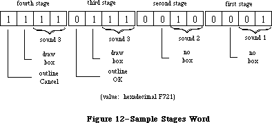 Figure 12–Sample Stages Word
_______________________________________________________________________________
»Item Lists in a Resource File
The resource type for an item list is 'DITL'. The resource data has the following format:
Number of bytes Contents
2 bytes Number of items in list minus 1
For each item:
4 bytes 0 (placeholder for handle or procedure pointer)
8 bytes Display rectangle (local coordinates)
1 byte Item type
1 byte Length of following data in bytes
n bytes If item type is: Content is:
(n is even) ctrlItem+resCtrl Resource ID (length 2)
any other ctrlItem Title of the control
statText, editText The text
iconItem, picItem Resource ID (length 2)
userItem Empty (length 0)
As shown here, the first four bytes for each item serve as a placeholder for the item’s handle or, for item type userItem, its procedure pointer; the handle or pointer is stored after the item list is read into memory. After the display rectangle and the item type, there’s a byte that gives the length of the data that follows: For a text item, the data is the text itself; for an icon, picture, or control of type ctrlItem+resCtrl, it’s the two-byte resource ID for the item; and for any other type of control, it’s the title of the control. For userItems, no data is specified. When the data is text or a control title, the number of bytes it occupies must be even to ensure word alignment of the next item.
Note: The text in the item list can’t be more than 240 characters long.
Assembly-language note: Offsets into the fields of an item list are
available as global constants; they’re listed
in the summary.
_______________________________________________________________________________
»SUMMARY OF THE DIALOG MANAGER
_______________________________________________________________________________
Constants
CONST
{ Item types }
ctrlItem = 4; {add to following four constants}
btnCtrl = 0; {standard button control}
chkCtrl = 1; {standard check box control}
radCtrl = 2; {standard radio button control}
resCtrl = 3; {control defined in control template}
statText = 8; {static text}
editText = 16; {editable text (dialog only)}
iconItem = 32; {icon}
picItem = 64; {QuickDraw picture}
userItem = 0; {application-defined item (dialog only)}
itemDisable = 128; {add to any of above to disable}
{ Item numbers of OK and Cancel buttons }
ok = 1;
cancel = 2;
{ Resource IDs of alert icons }
stopIcon = 0;
noteIcon = 1;
cautionIcon = 2;
{ Constants for TextEdit and dialog boxes }
TEdoFont = 1; {set font (family) number}
TEdoFace = 2; {set character style}
TEdoSize = 4; {set type size}
TEdoColor = 8; {set foreground color}
TEdoAll = 15; {set all attributes}
TEaddSize = 16; {adjust type size}
{ Constants for dialog boxes only }
doBColor = 8192; {set background color}
doMode = 16384; {set txMode}
doFontName = 32768; {set txFont from name}
_______________________________________________________________________________
Data Types
TYPE
DialogPtr = WindowPtr;
DialogPeek = ^DialogRecord;
DialogRecord = RECORD
window: WindowRecord; {dialog window}
items: Handle; {item list}
textH: TEHandle; {current editText item}
editField: INTEGER; {editText item number minus 1}
editOpen: INTEGER; {used internally}
aDefItem: INTEGER {default button item number}
END;
DialogTHndl = ^DialogTPtr;
DialogTPtr = ^DialogTemplate;
DialogTemplate = RECORD
boundsRect: Rect; {becomes window's portRect}
procID: INTEGER; {window definiton ID}
visible: BOOLEAN; {TRUE if visible}
filler1: BOOLEAN; {not used}
goAwayFlag: BOOLEAN; {TRUE if has go-away region}
filler2: BOOLEAN; {not used}
refCon: LONGINT; {window's reference value}
itemsID: INTEGER; {resource ID of item list}
title: Str255 {window's title}
END;
AlertTHndl = ^AlertTPtr;
AlertTPtr = ^AlertTemplate;
AlertTemplate = RECORD
boundsRect: Rect; {becomes window's portRect}
itemsID: INTEGER; {resource ID of item list}
stages: StageList {alert stage information}
END;
StageList = PACKED RECORD
boldItm4: 0..1; {default button item number minus 1}
boxDrwn4: BOOLEAN; {TRUE if alert box to be drawn}
sound4: 0..3 {sound number}
boldItm3: 0..1;
boxDrwn3: BOOLEAN;
sound3: 0..3
boldItm2: 0..1;
boxDrwn2: BOOLEAN;
sound2: 0..3
boldItm1: 0..1;
boxDrwn1: BOOLEAN;
sound1: 0..3
END;
_______________________________________________________________________________
Routines
Initialization
PROCEDURE InitDialogs (resumeProc: ProcPtr);
PROCEDURE ErrorSound (soundProc: ProcPtr);
PROCEDURE SetDAFont (fontNum: INTEGER); [Not in ROM]
Creating and Disposing of Dialogs
FUNCTION NewDialog (dStorage: Ptr; boundsRect: Rect; title: Str255;
visible: BOOLEAN; procID: INTEGER;
behind: WindowPtr; goAwayFlag: BOOLEAN;
refCon: LONGINT; items: Handle) : DialogPtr;
FUNCTION NewCDialog (dStorage: Ptr; boundsRect: Rect; title: Str255;
visible: BOOLEAN; procID: INTEGER;
behind: WindowPtr; goAwayFlag: BOOLEAN;
refCon: LONGINT; items: Handle) : CDialogPtr;
FUNCTION GetNewDialog (dialogID: INTEGER; dStorage: Ptr;
behind: WindowPtr) : DialogPtr;
PROCEDURE CloseDialog (theDialog: DialogPtr);
PROCEDURE DisposDialog (theDialog: DialogPtr);
PROCEDURE CouldDialog (dialogID: INTEGER);
PROCEDURE FreeDialog (dialogID: INTEGER);
Handling Dialog Events
PROCEDURE ModalDialog (filterProc: ProcPtr; VAR itemHit: INTEGER);
FUNCTION IsDialogEvent (theEvent: EventRecord) : BOOLEAN;
FUNCTION DialogSelect (theEvent: EventRecord; VAR theDialog: DialogPtr;
VAR itemHit: INTEGER) : BOOLEAN;
PROCEDURE DlgCut (theDialog: DialogPtr); [Not in ROM]
PROCEDURE DlgCopy (theDialog: DialogPtr); [Not in ROM]
PROCEDURE DlgPaste (theDialog: DialogPtr); [Not in ROM]
PROCEDURE DlgDelete (theDialog: DialogPtr); [Not in ROM]
PROCEDURE DrawDialog (theDialog: DialogPtr);
PROCEDURE UpdtDialog (theDialog: DialogPtr; updateRgn: RgnHandle);
Invoking Alerts
FUNCTION Alert (alertID: INTEGER; filterProc: ProcPtr) : INTEGER;
FUNCTION StopAlert (alertID: INTEGER; filterProc: ProcPtr) : INTEGER;
FUNCTION NoteAlert (alertID: INTEGER; filterProc: ProcPtr) : INTEGER;
FUNCTION CautionAlert (alertID: INTEGER; filterProc: ProcPtr) : INTEGER;
PROCEDURE CouldAlert (alertID: INTEGER);
PROCEDURE FreeAlert (alertID: INTEGER);
Manipulating Items in Dialogs and Alerts
PROCEDURE ParamText (param0,param1,param2,param3: Str255);
PROCEDURE GetDItem (theDialog: DialogPtr; itemNo: INTEGER;
VAR itemType: INTEGER; VAR item: Handle;
VAR box: Rect);
PROCEDURE SetDItem (theDialog: DialogPtr; itemNo: INTEGER;
itemType: INTEGER; item: Handle; box: Rect);
PROCEDURE HideDItem (theDialog: DialogPtr; itemNo: INTEGER);
PROCEDURE ShowDItem (theDialog: DialogPtr; itemNo: INTEGER);
FUNCTION FindDItem (theDialog: DialogPtr; thePt: Point) : INTEGER;
PROCEDURE GetIText (item: Handle; VAR text: Str255);
PROCEDURE SetIText (item: Handle; text: Str255);
PROCEDURE SelIText (theDialog: DialogPtr; itemNo: INTEGER;
strtSel,endSel: INTEGER);
FUNCTION GetAlrtStage : INTEGER; [Not in ROM]
PROCEDURE ResetAlrtStage; [Not in ROM]
_______________________________________________________________________________
UserItem Procedure
PROCEDURE MyItem (theWindow: WindowPtr; itemNo: INTEGER);
_______________________________________________________________________________
Sound Procedure
PROCEDURE MySound (soundNo: INTEGER);
_______________________________________________________________________________
FilterProc Function for Modal Dialogs and Alerts
FUNCTION MyFilter (theDialog: DialogPtr; VAR theEvent: EventRecord;
VAR itemHit: INTEGER) : BOOLEAN;
_______________________________________________________________________________
Assembly-Language Information
Constants
; Item types
ctrlItem .EQU 4 ;add to following four constants
btnCtrl .EQU 0 ;standard button control
chkCtrl .EQU 1 ;standard check box control
radCtrl .EQU 2 ;standard radio button control
resCtrl .EQU 3 ;control defined in control template
statText .EQU 8 ;static text
editText .EQU 16 ;editable text (dialog only)
iconItem .EQU 32 ;icon
picItem .EQU 64 ;QuickDraw picture
userItem .EQU 0 ;application-defined item (dialog only)
itemDisable .EQU 128 ;add to any of above to disable
; Item numbers of OK and Cancel buttons
okButton .EQU 1
cancelButton .EQU 2
; Resource IDs of alert icons
stopIcon .EQU 0
noteIcon .EQU 1
cautionIcon .EQU 2
; Masks for stages word in alert template
volBits .EQU 3 ;sound number
alBit .EQU 4 ;whether to draw box
okDismissal .EQU 8 ;item number of default button minus 1
Dialog Record Data Structure
dWindow Dialog window
items Handle to dialog’s item list
teHandle Handle to current editText item
editField Item number of editText item minus 1 (word)
aDefItem Item number of default button (word)
dWindLen Size in bytes of dialog record
Dialog Template Data Structure
dBounds Rectangle that becomes portRect of dialog window’s
grafPort (8 bytes)
dWindProc Window definition ID (word)
dVisible Nonzero if dialog window is visible (word)
dGoAway Nonzero if dialog window has a go-away region (word)
dRefCon Dialog window’s reference value (long)
dItems Resource ID of dialog’s item list (word)
dTitle Dialog window’s title (preceded by length byte)
Alert Template Data Structure
aBounds Rectangle that becomes portRect of alert window’s
grafPort (8 bytes)
aItems Resource ID of alert’s item list (word)
aStages Stages word; information for alert stages
Item List Data Structure
dlgMaxIndex Number of items minus 1 (word)
itmHndl Handle or procedure pointer for this item
itmRect Display rectangle for this item (8 bytes)
itmType Item type for this item (byte)
itmData Length byte followed by data for this item
(data must be even number of bytes)
Variables
ResumeProc Address of resume procedure
DAStrings Handles to ParamText strings (16 bytes)
DABeeper Address of current sound procedure
DlgFont Font number for dialogs and alerts (word)
ACount Stage number (0 through 3) of last alert (word)
ANumber Resource ID of last alert (word)
Further Reference:
_______________________________________________________________________________
Resource Manager
QuickDraw
Toolbox Event Manager
Window Manager
Control Manager
TextEdit
Technical Note #4, Error Returns from GetNewDialog
Technical Note #5, Using Modeless Dialogs from Desk Accessories
Technical Note #34, User Items in Dialogs
Technical Note #95, How To Add Items to the Print Dialogs
Technical Note #112, FindDItem
Technical Note #203, Don’t Abuse the Managers
Technical Note #251, Safe cdevs
Figure 12–Sample Stages Word
_______________________________________________________________________________
»Item Lists in a Resource File
The resource type for an item list is 'DITL'. The resource data has the following format:
Number of bytes Contents
2 bytes Number of items in list minus 1
For each item:
4 bytes 0 (placeholder for handle or procedure pointer)
8 bytes Display rectangle (local coordinates)
1 byte Item type
1 byte Length of following data in bytes
n bytes If item type is: Content is:
(n is even) ctrlItem+resCtrl Resource ID (length 2)
any other ctrlItem Title of the control
statText, editText The text
iconItem, picItem Resource ID (length 2)
userItem Empty (length 0)
As shown here, the first four bytes for each item serve as a placeholder for the item’s handle or, for item type userItem, its procedure pointer; the handle or pointer is stored after the item list is read into memory. After the display rectangle and the item type, there’s a byte that gives the length of the data that follows: For a text item, the data is the text itself; for an icon, picture, or control of type ctrlItem+resCtrl, it’s the two-byte resource ID for the item; and for any other type of control, it’s the title of the control. For userItems, no data is specified. When the data is text or a control title, the number of bytes it occupies must be even to ensure word alignment of the next item.
Note: The text in the item list can’t be more than 240 characters long.
Assembly-language note: Offsets into the fields of an item list are
available as global constants; they’re listed
in the summary.
_______________________________________________________________________________
»SUMMARY OF THE DIALOG MANAGER
_______________________________________________________________________________
Constants
CONST
{ Item types }
ctrlItem = 4; {add to following four constants}
btnCtrl = 0; {standard button control}
chkCtrl = 1; {standard check box control}
radCtrl = 2; {standard radio button control}
resCtrl = 3; {control defined in control template}
statText = 8; {static text}
editText = 16; {editable text (dialog only)}
iconItem = 32; {icon}
picItem = 64; {QuickDraw picture}
userItem = 0; {application-defined item (dialog only)}
itemDisable = 128; {add to any of above to disable}
{ Item numbers of OK and Cancel buttons }
ok = 1;
cancel = 2;
{ Resource IDs of alert icons }
stopIcon = 0;
noteIcon = 1;
cautionIcon = 2;
{ Constants for TextEdit and dialog boxes }
TEdoFont = 1; {set font (family) number}
TEdoFace = 2; {set character style}
TEdoSize = 4; {set type size}
TEdoColor = 8; {set foreground color}
TEdoAll = 15; {set all attributes}
TEaddSize = 16; {adjust type size}
{ Constants for dialog boxes only }
doBColor = 8192; {set background color}
doMode = 16384; {set txMode}
doFontName = 32768; {set txFont from name}
_______________________________________________________________________________
Data Types
TYPE
DialogPtr = WindowPtr;
DialogPeek = ^DialogRecord;
DialogRecord = RECORD
window: WindowRecord; {dialog window}
items: Handle; {item list}
textH: TEHandle; {current editText item}
editField: INTEGER; {editText item number minus 1}
editOpen: INTEGER; {used internally}
aDefItem: INTEGER {default button item number}
END;
DialogTHndl = ^DialogTPtr;
DialogTPtr = ^DialogTemplate;
DialogTemplate = RECORD
boundsRect: Rect; {becomes window's portRect}
procID: INTEGER; {window definiton ID}
visible: BOOLEAN; {TRUE if visible}
filler1: BOOLEAN; {not used}
goAwayFlag: BOOLEAN; {TRUE if has go-away region}
filler2: BOOLEAN; {not used}
refCon: LONGINT; {window's reference value}
itemsID: INTEGER; {resource ID of item list}
title: Str255 {window's title}
END;
AlertTHndl = ^AlertTPtr;
AlertTPtr = ^AlertTemplate;
AlertTemplate = RECORD
boundsRect: Rect; {becomes window's portRect}
itemsID: INTEGER; {resource ID of item list}
stages: StageList {alert stage information}
END;
StageList = PACKED RECORD
boldItm4: 0..1; {default button item number minus 1}
boxDrwn4: BOOLEAN; {TRUE if alert box to be drawn}
sound4: 0..3 {sound number}
boldItm3: 0..1;
boxDrwn3: BOOLEAN;
sound3: 0..3
boldItm2: 0..1;
boxDrwn2: BOOLEAN;
sound2: 0..3
boldItm1: 0..1;
boxDrwn1: BOOLEAN;
sound1: 0..3
END;
_______________________________________________________________________________
Routines
Initialization
PROCEDURE InitDialogs (resumeProc: ProcPtr);
PROCEDURE ErrorSound (soundProc: ProcPtr);
PROCEDURE SetDAFont (fontNum: INTEGER); [Not in ROM]
Creating and Disposing of Dialogs
FUNCTION NewDialog (dStorage: Ptr; boundsRect: Rect; title: Str255;
visible: BOOLEAN; procID: INTEGER;
behind: WindowPtr; goAwayFlag: BOOLEAN;
refCon: LONGINT; items: Handle) : DialogPtr;
FUNCTION NewCDialog (dStorage: Ptr; boundsRect: Rect; title: Str255;
visible: BOOLEAN; procID: INTEGER;
behind: WindowPtr; goAwayFlag: BOOLEAN;
refCon: LONGINT; items: Handle) : CDialogPtr;
FUNCTION GetNewDialog (dialogID: INTEGER; dStorage: Ptr;
behind: WindowPtr) : DialogPtr;
PROCEDURE CloseDialog (theDialog: DialogPtr);
PROCEDURE DisposDialog (theDialog: DialogPtr);
PROCEDURE CouldDialog (dialogID: INTEGER);
PROCEDURE FreeDialog (dialogID: INTEGER);
Handling Dialog Events
PROCEDURE ModalDialog (filterProc: ProcPtr; VAR itemHit: INTEGER);
FUNCTION IsDialogEvent (theEvent: EventRecord) : BOOLEAN;
FUNCTION DialogSelect (theEvent: EventRecord; VAR theDialog: DialogPtr;
VAR itemHit: INTEGER) : BOOLEAN;
PROCEDURE DlgCut (theDialog: DialogPtr); [Not in ROM]
PROCEDURE DlgCopy (theDialog: DialogPtr); [Not in ROM]
PROCEDURE DlgPaste (theDialog: DialogPtr); [Not in ROM]
PROCEDURE DlgDelete (theDialog: DialogPtr); [Not in ROM]
PROCEDURE DrawDialog (theDialog: DialogPtr);
PROCEDURE UpdtDialog (theDialog: DialogPtr; updateRgn: RgnHandle);
Invoking Alerts
FUNCTION Alert (alertID: INTEGER; filterProc: ProcPtr) : INTEGER;
FUNCTION StopAlert (alertID: INTEGER; filterProc: ProcPtr) : INTEGER;
FUNCTION NoteAlert (alertID: INTEGER; filterProc: ProcPtr) : INTEGER;
FUNCTION CautionAlert (alertID: INTEGER; filterProc: ProcPtr) : INTEGER;
PROCEDURE CouldAlert (alertID: INTEGER);
PROCEDURE FreeAlert (alertID: INTEGER);
Manipulating Items in Dialogs and Alerts
PROCEDURE ParamText (param0,param1,param2,param3: Str255);
PROCEDURE GetDItem (theDialog: DialogPtr; itemNo: INTEGER;
VAR itemType: INTEGER; VAR item: Handle;
VAR box: Rect);
PROCEDURE SetDItem (theDialog: DialogPtr; itemNo: INTEGER;
itemType: INTEGER; item: Handle; box: Rect);
PROCEDURE HideDItem (theDialog: DialogPtr; itemNo: INTEGER);
PROCEDURE ShowDItem (theDialog: DialogPtr; itemNo: INTEGER);
FUNCTION FindDItem (theDialog: DialogPtr; thePt: Point) : INTEGER;
PROCEDURE GetIText (item: Handle; VAR text: Str255);
PROCEDURE SetIText (item: Handle; text: Str255);
PROCEDURE SelIText (theDialog: DialogPtr; itemNo: INTEGER;
strtSel,endSel: INTEGER);
FUNCTION GetAlrtStage : INTEGER; [Not in ROM]
PROCEDURE ResetAlrtStage; [Not in ROM]
_______________________________________________________________________________
UserItem Procedure
PROCEDURE MyItem (theWindow: WindowPtr; itemNo: INTEGER);
_______________________________________________________________________________
Sound Procedure
PROCEDURE MySound (soundNo: INTEGER);
_______________________________________________________________________________
FilterProc Function for Modal Dialogs and Alerts
FUNCTION MyFilter (theDialog: DialogPtr; VAR theEvent: EventRecord;
VAR itemHit: INTEGER) : BOOLEAN;
_______________________________________________________________________________
Assembly-Language Information
Constants
; Item types
ctrlItem .EQU 4 ;add to following four constants
btnCtrl .EQU 0 ;standard button control
chkCtrl .EQU 1 ;standard check box control
radCtrl .EQU 2 ;standard radio button control
resCtrl .EQU 3 ;control defined in control template
statText .EQU 8 ;static text
editText .EQU 16 ;editable text (dialog only)
iconItem .EQU 32 ;icon
picItem .EQU 64 ;QuickDraw picture
userItem .EQU 0 ;application-defined item (dialog only)
itemDisable .EQU 128 ;add to any of above to disable
; Item numbers of OK and Cancel buttons
okButton .EQU 1
cancelButton .EQU 2
; Resource IDs of alert icons
stopIcon .EQU 0
noteIcon .EQU 1
cautionIcon .EQU 2
; Masks for stages word in alert template
volBits .EQU 3 ;sound number
alBit .EQU 4 ;whether to draw box
okDismissal .EQU 8 ;item number of default button minus 1
Dialog Record Data Structure
dWindow Dialog window
items Handle to dialog’s item list
teHandle Handle to current editText item
editField Item number of editText item minus 1 (word)
aDefItem Item number of default button (word)
dWindLen Size in bytes of dialog record
Dialog Template Data Structure
dBounds Rectangle that becomes portRect of dialog window’s
grafPort (8 bytes)
dWindProc Window definition ID (word)
dVisible Nonzero if dialog window is visible (word)
dGoAway Nonzero if dialog window has a go-away region (word)
dRefCon Dialog window’s reference value (long)
dItems Resource ID of dialog’s item list (word)
dTitle Dialog window’s title (preceded by length byte)
Alert Template Data Structure
aBounds Rectangle that becomes portRect of alert window’s
grafPort (8 bytes)
aItems Resource ID of alert’s item list (word)
aStages Stages word; information for alert stages
Item List Data Structure
dlgMaxIndex Number of items minus 1 (word)
itmHndl Handle or procedure pointer for this item
itmRect Display rectangle for this item (8 bytes)
itmType Item type for this item (byte)
itmData Length byte followed by data for this item
(data must be even number of bytes)
Variables
ResumeProc Address of resume procedure
DAStrings Handles to ParamText strings (16 bytes)
DABeeper Address of current sound procedure
DlgFont Font number for dialogs and alerts (word)
ACount Stage number (0 through 3) of last alert (word)
ANumber Resource ID of last alert (word)
Further Reference:
_______________________________________________________________________________
Resource Manager
QuickDraw
Toolbox Event Manager
Window Manager
Control Manager
TextEdit
Technical Note #4, Error Returns from GetNewDialog
Technical Note #5, Using Modeless Dialogs from Desk Accessories
Technical Note #34, User Items in Dialogs
Technical Note #95, How To Add Items to the Print Dialogs
Technical Note #112, FindDItem
Technical Note #203, Don’t Abuse the Managers
Technical Note #251, Safe cdevs
The Disk Driver
_______________________________________________________________________________
THE DISK DRIVER
_______________________________________________________________________________
About This Chapter
About the Disk Driver
Using the Disk Driver
Disk Driver Routines
Advanced Control Calls
Assembly-Language Example
Summary of the Disk Driver
_______________________________________________________________________________
»ABOUT THIS CHAPTER
_______________________________________________________________________________
The Disk Driver is a Macintosh device driver used for storing and retrieving information on Macintosh 3 1/2-inch disk drives. This chapter describes the Disk Driver in detail. It’s intended for programmers who want to access Macintosh drives directly, bypassing the File Manager.
You should already be familiar with:
• events, as discussed in the Toolbox Event Manager and Operating
System Event Manager chapters
• files and disk drives, as described in the File Manager chapter
• interrupts and the use of devices and device drivers, as described
in the Device Manager chapter
_______________________________________________________________________________
»ABOUT THE DISK DRIVER
_______________________________________________________________________________
Note: The extensions to the Disk Driver described in this chapter were
originally documented in Inside Macintosh, Volumes IV and V. As such,
the Volume IV information refers to the 128K ROM and System file
version 3.2 and later, while the Volume V information refers to the
Macintosh SE and Macintosh II ROMs and System file version 4.1 and
later. The sections of this chapter that cover these extensions are
so noted.
The Disk Driver is a standard Macintosh device driver in ROM. It allows Macintosh applications to read from disks, write to disks, and eject disks.
Note: The Disk Driver cannot format disks; this task is accomplished by
the Disk Initialization Package.
Information on disks is stored in 512-byte sectors. There are 800 sectors on one 400K-byte Macintosh disk. Each sector consists of an address mark that contains information used by the Disk Driver to determine the position of the sector on the disk, and a data mark that primarily contains data stored in that sector.
Consecutive sectors on a disk are grouped into tracks. There are 80 tracks on one 400K-byte Macintosh disk. Track 0 is the outermost and track 79 is the innermost. Each track corresponds to a ring of constant radius around the disk.
Macintosh disks are formatted in a manner that allows a more efficient use of disk space than most microcomputer formatting schemes: The tracks are divided into five groups of 16 tracks each, and each group of tracks is accessed at a different rotational speed from the other groups. (Those at the edge of the disk are accessed at slower speeds than those toward the center.)
Each group of tracks contains a different number of sectors:
Tracks Sectors per track Sectors
0-15 12 0-191
16-31 11 192-367
32-47 10 368-527
48-63 9 528-671
64-79 8 672-799
An application can read or write data in whole disk sectors only. The application must specify the data to be read or written in 512-byte multiples, and the Disk Driver automatically calculates which sector to access. The application specifies where on the disk the data should be read or written by providing a positioning mode and a positioning offset. Data can be read from or written to the disk:
• at the current sector on the disk (the sector following the
last sector read or written)
• from a position relative to the current sector on the disk
• from a position relative to the beginning of first sector on the disk
The following constants are used to specify the positioning mode:
CONST fsAtMark = 0; {at current sector}
fsFromStart = 1; {relative to first sector}
fsFromMark = 3; {relative to current sector}
If the positioning mode is relative to a sector (fsFromStart or fsFromMark), the relative offset from that sector must be given as a 512-byte multiple.
In addition to the 512 bytes of standard information, each sector contains 12 bytes of file tags. The file tags are designed to allow easy reconstruction of files from a volume whose directory or other file-access information has been destroyed. Whenever the Disk Driver reads a sector from a disk, it places the sector’s file tags at a special location in low memory called the file tags buffer (the remaining 512 bytes in the sector are passed on to the File
Manager). Each time one sector’s file tags are written there, the previous file tags are overwritten. Conversely, whenever the Disk Driver writes a sector on a disk, it takes the 12 bytes in the file tags buffer and writes them on the disk.
Assembly-language note: The information in the file tags buffer can be
accessed through the following global variables:
Name Contents
BufTgFNum File number (long)
BufTgFFlag Flags (word: bit 1=1 if resource fork)
BufTgFBkNum Logical block number (word)
BufTgDate Date and time of last modification (long)
The logical block number indicates which relative portion of a file the block contains—the first logical block of a file is numbered 0, the second is numbered 1, and so on.
The Disk Driver disables interrupts during disk accesses. While interrupts are disabled, it stores any serial data received via the modem port and later passes the data to the Serial Driver. This allows the modem port to be used simultaneously with disk accesses without fear of hardware overrun errors. (For more information, see the Serial Drivers chapter.)
Note: The extensions to the Disk Driver described in the following paragraphs
were originally documented in Inside Macintosh, Volume IV. As such,
this information refers to the 128K ROMs and System file version 3.2
and later.
The Disk Driver has been extended to support the double-sided 3 1/2-inch drive and the Apple Hard Disk 20™ drive; support for the single-sided 3 1/2-inch drive is of course maintained. A second Hard Disk 20 drive, an external double-sided drive, or an external single-sided drive can also be connected through the pass-through connector of a Hard Disk 20.
The Disk Driver's name remains '.Sony' and the reference number for 3 1/2-inch drives (both single-sided and double-sided) is still –5. The drive numbers for the 3 1/2-inch drives—1 for the internal drive and 2 for the external drive—are also unchanged.
The Hard Disk 20 has a reference number of –2 and drive numbers of 3 and 4. The Hard Disk 20 returns 20 tag bytes per sector instead of the 12 bytes returned by the 3 1/2-inch drives.
The new Disk Driver ignores KillIO calls; as before, you cannot make immediate calls to this driver. Read-verify mode is still supported for 3 1/2-inch drives, but has no effect on hard disk drives. A new track cache feature speeds the disk access on 3 1/2-inch drives; an advance control call (described below) let you control this feature.
The DiskEject function, if used with a hard disk drive, returns the Device Manager result code controlErr; at the next Disk Driver vertical retrace task, a disk-in-place event is reposted for that drive.
Assembly-language note: The additional eight bytes of tag data for the
Hard Disk 20 are stored in the global variable
TFSTagData.
Note: The extensions to the Disk Driver described in the following paragraphs
were originally documented in Inside Macintosh, Volume V. As such,
this information refers to the Macintosh SE and Macintosh II ROMs and
System file version 4.1 and later.
In earlier versions of the Disk Driver, each drive, whether electrically connected or not, is assigned its own, hard-coded drive number—the internal and external 3.5-inch drives have drive numbers 1 and 2, while Hard Disk 20 drives have drive numbers 3 and 4.
The new Disk Driver determines which drives are electrically connected and then dynamically assigns drive numbers, leaving no gaps for missing drives. This translation from drive to logical drive number means that a drive number might not correspond to the drive’s physical, or electrical, address. For instance, on a Macintosh SE with one internal drive and one external drive, without translation the internal drive would be given drive number 1 and the external drive number 3 (drive number 2 belonging to the missing internal drive). With translation, the two connected drives are assigned logical drive numbers 1
and 2.
Warning: Programs (such as copy-protection programs) that expect a given
physical drive to have a permanently-assigned drive number will
need to be modified in order to run under the new Disk Driver.
_______________________________________________________________________________
»USING THE DISK DRIVER
_______________________________________________________________________________
The Disk Driver is opened automatically when the system starts up. It allocates space in the system heap for variables, installs entries in the drive queue for each drive that’s attached to the Macintosh, and installs a task into the vertical retrace queue. The Disk Driver’s name is '.Sony', and its reference number is –5.
To write data onto a disk, make a Device Manager Write call. You must pass the following parameters:
• the driver reference number –5
• the drive number 1 (internal drive) or 2 (external drive)
• a positioning mode indicating where on the disk the information
should be written
• a positioning offset that’s a multiple of 512 bytes
• a buffer that contains the data you want to write
• the number of bytes (in multiples of 512) that you want to write
The Disk Driver’s prime routine returns one of the following result codes to the Write function:
noErr No error
nsDrvErr No such drive
paramErr Bad positioning information
wPrErr Volume is locked by a hardware setting
firstDskErr Low-level disk error
through lastDskErr
To read data from a disk, make a Device Manager Read call. You must pass the following parameters:
• the driver reference number –5
• the drive number 1 (internal drive) or 2 (external drive)
• a positioning mode indicating where on the disk the information
should be read from
• a positioning offset that’s a multiple of 512 bytes
• a buffer to receive the data that’s read
• the number of bytes (in multiples of 512) that you want to read
The Disk Driver’s prime routine returns one of the following result codes to the Read function:
noErr No error
nsDrvErr No such drive
paramErr Bad positioning information
firstDskErr Low-level disk error
through lastDskErr
To verify that data written to a disk exactly matches the data in memory, make a Device Manager Read call right after the Write call. The parameters for a read-verify operation are the same as for a standard Read call, except that the following constant must be added to the positioning mode:
CONST rdVerify = 64; {read-verify mode}
The result code dataVerErr will be returned if any of the data doesn’t match.
The Disk Driver can read and write sectors in any order, and therefore operates faster on one large data request than it would on a series of equivalent but smaller data requests.
There are three different calls you can make to the Disk Driver’s control routine:
• KillIO causes all current I/O requests to be aborted. KillIO is
a Device Manager call.
• SetTagBuffer specifies the information to be used in the file tags buffer.
• DiskEject ejects a disk from a drive.
An application using the File Manager should always unmount the volume in a drive before ejecting the disk.
You can make one call, DriveStatus, to the Disk Driver’s status routine, to learn about the state of the driver.
An application can bypass the implicit mounting of volumes done by the File Manager by calling the Operating System Event Manager function GetOSEvent and looking for disk-inserted events. Once the volume has been inserted in the drive, it can be read from normally.
_______________________________________________________________________________
»DISK DRIVER ROUTINES
_______________________________________________________________________________
The Disk Driver routines return an integer result code of type OSErr; each routine description lists all of the applicable result codes.
FUNCTION DiskEject (drvNum: INTEGER) : OSErr; [Not in ROM]
Assembly-language note: DiskEject is equivalent to a Control call with
csCode equal to the global constant ejectCode.
DiskEject ejects the disk from the internal drive if drvNum is 1, or from the external drive if drvNum is 2.
Result codes noErr No error
nsDrvErr No such drive
FUNCTION SetTagBuffer (buffPtr: Ptr) : OSErr; [Not in ROM]
Assembly-language note: SetTagBuffer is equivalent to a Control call with
csCode equal to the global constant tgBuffCode.
An application can change the information used in the file tags buffer by calling SetTagBuffer. The buffPtr parameter points to a buffer that contains the information to be used. If buffPtr is NIL, the information in the file tags buffer isn’t changed.
If buffPtr isn’t NIL, every time the Disk Driver reads a sector from the disk, it stores the file tags in the file tags buffer and in the buffer pointed to by buffPtr. Every time the Disk Driver writes a sector onto the disk, it reads 12 bytes from the buffer pointed to by buffPtr, places them in the file tags buffer, and then writes them onto the disk.
The contents of the buffer pointed to by buffPtr are overwritten at the end of every read request (which can be composed of a number of sectors) instead of at the end of every sector. Each read request places 12 bytes in the buffer for each sector, always beginning at the start of the buffer. This way an application can examine the file tags for a number of sequentially read sectors. If a read request is composed of a number of sectors, the Disk Driver places 12 bytes in the buffer for each sector. For example, for a read request of five sectors, the Disk Driver will place 60 bytes in the buffer.
Result codes noErr No error
FUNCTION DriveStatus (drvNum: INTEGER; VAR status: DrvSts) : OSErr;
[Not in ROM]
Assembly-language note: DriveStatus is equivalent to a Status call with
csCode equal to the global constant drvStsCode;
status is returned in csParam through csParam+21.
DriveStatus returns information about the internal drive if drvNum is 1, or about the external drive if drvNum is 2. The information is returned in a record of type DrvSts:
TYPE DrvSts = RECORD
track: INTEGER; {current track}
writeProt: SignedByte; {bit 7=1 if volume is locked}
diskInPlace: SignedByte; {disk in place}
installed: SignedByte; {drive installed}
sides: SignedByte; {bit 7=0 if single-side drive}
qLink: QElemPtr; {next queue entry}
qType: INTEGER; {reserved for future use}
dQDrive: INTEGER; {drive number}
dQRefNum: INTEGER; {driver reference number}
dQFSID: INTEGER; {file-system identifier}
twoSideFmt: SignedByte; {-1 if two-sided disk}
needsFlush: SignedByte; {reserved for future use}
diskErrs: INTEGER {error count}
END;
The diskInPlace field is 0 if there’s no disk in the drive, 1 or 2 if there is a disk in the drive, or –4 to –1 if the disk was ejected in the last 1.5 seconds. The installed field is 1 if the drive is connected to the Macintosh, 0 if the drive might be connected to the Macintosh, and –1 if the drive isn’t installed. The value of twoSideFmt is valid only when diskInPlace=2. The value of diskErrs is incremented every time an error occurs internally within the Disk Driver.
Result codes noErr No error
nsDrvErr No such drive
_______________________________________________________________________________
»ADVANCED CONTROL CALLS
_______________________________________________________________________________
This section describes several advanced control calls used by the Operating System; you will probably have no need to use them.
Note: The extensions to the Disk Driver described in the following paragraphs
were originally documented in Inside Macintosh, Volume IV. As such,
this information refers to the 128K ROMs and System file version 3.2
and later.
csCode = 5
This call verifies that the disk in the drive specified by ioRefNum in the parameter block data structure (including hard disks) is correctly formatted.
csCode = 6 csParam = integer
This call formats the disk in the drive specified by ioRefNum in the parameter block data structure. With the Hard Disk 20, it zeros all blocks. A csParam value of 1 causes it to format a single-sided 3 1/2-inch disk in a double-sided drive; otherwise, the value of csParam should be 0.
Warning: Use this call with care. It’s normally used only by the
Disk Initialization Package.
csCode = 9 csParam = integer
This call controls the track cache feature. The high-order byte of csParam is nonzero to enable the cache feature and 0 to disable it. The low-order byte of csParam is 1 to install the cache, –1 to remove it, and 0 to do neither. The cache is located in the system heap; the driver will relinquish cache space, if necessary, when the GrowZone function is called for the system heap.
csCode = 21 csParam = ptr (long)
This call works only with the Hard Disk 20; it returns a pointer to an icon data structure whose format is identical to that of an 'ICN#' resource. The drive number must be in ioRefNum in the parameter block data structure.
Note: The extensions to the Disk Driver described in the following paragraphs
were originally documented in Inside Macintosh, Volume V. As such,
this information refers to the Macintosh SE and Macintosh II ROMs and
System file version 4.1 and later.
csCode = 21 csParam = ptr (long)
X-Ref: Technical Note #28
This call previously worked only with the Hard Disk 20; with drive number translation, it’s been extended to support all drives. For the drive whose drive number (remember, this will be a logical drive number) is specified in ioDrvNum, this call returns a pointer to a data structure consisting of an icon, a mask icon, and a Pascal string. This icon typically describes the disk media. The string is used in the Get Info dialog (after the word “Where:”) to specify the physical drive associated with the icon. The Disk Driver leaves this string null, letting the Finder fill in this information. (Your own driver would need to supply this string.)
csCode = 22 csParam = ptr (long)
For the drive whose drive number is specified in ioDrvNum, this call returns a pointer to an icon and a mask icon. This icon typically describes the physical drive.
csCode = 23 csParam = long
This call returns information about the drive’s physical location, size, and other characteristics. The low-order byte of csParam specifies the drive type and can contain one of the following values:
Value Meaning
0 No such drive
1 Unspecified drive
2 400K drive
3 800K drive
4 Reserved
5 Reserved
6 Reserved
7 Hard Disk 20
Bits 8 through 11 of csParam specify the drive attributes, as follows:
Bit Meaning
8 Set for external drives, clear for internal drive
9 Set if SCSI drive, clear if IWM
10 Set if drive is fixed, clear if drive can be removed
11 Set for secondary drives, clear for primary drive
The remaining bits of csParam are reserved for future use.
_______________________________________________________________________________
»ASSEMBLY-LANGUAGE EXAMPLE
_______________________________________________________________________________
The following assembly-language example ejects the disk in drive 1:
MyEject MOVEQ #<ioVQElSize/2>-1,D0 ;prepare an I/O
@1 CLR.W -(SP) ; parameter block
DBRA D0,@1 ; on the stack
MOVE.L SP,A0 ;A0 points to it
MOVE.W #-5,ioRefNum(A0) ;driver refNum
MOVE.W #1,ioDrvNum(A0) ;internal drive
MOVE.W #ejectCode,csCode(A0) ;eject control code
_Eject ;synchronous call
ADD #ioVQElSize,SP ;clean up stack
To asynchronously read sector 4 from the disk in drive 1, you would do the following:
MyRead MOVEQ #<ioQElSize/2>-1,D0 ;prepare an I/O
@1 CLR.W -(SP) ; parameter block
DBRA D0,@1 ; on the stack
MOVE.L SP,A0 ;A0 points to it
MOVE.W #-5,ioRefNum(A0) ;driver refNum
MOVE.W #1,ioDrvNum(A0) ;internal drive
MOVE.W #1,ioPosMode(A0) ;absolute positioning
MOVE.L #<512*4>,ioPosOffset(A0) ;sector 4
MOVE.L #512,ioReqCount(A0) ;read one sector
LEA myBuffer,A1
MOVE.L A1,ioBuffer(A0) ;buffer address
_Read ,ASYNC ;read data
; Do any other processing here. Then, when the sector is needed:
@2 MOVE.W ioResult(A0),D0 ;wait for completion
BGT.S @2
ADD #ioQElSize,SP ;clean up stack
myBuffer .BLOCK 512,0
_______________________________________________________________________________
»SUMMARY OF THE DISK DRIVER
_______________________________________________________________________________
Constants
CONST
{ Positioning modes }
fsAtMark = 0; {at current sector}
fsFromStart = 1; {relative to first sector}
fsFromMark = 3; {relative to current sector}
rdVerify = 64; {add to above for read-verify}
_______________________________________________________________________________
Data Types
TYPE
DrvSts = RECORD
track: INTEGER; {current track}
writeProt: SignedByte; {bit 7=1 if volume is locked}
diskInPlace: SignedByte; {disk in place}
installed: SignedByte; {drive installed}
sides: SignedByte; {bit 7=0 if single-side drive}
qLink: QElemPtr; {next queue entry}
qType: INTEGER; {reserved for future use}
dQDrive: INTEGER; {drive number}
dQRefNum: INTEGER; {driver reference number}
dQFSID: INTEGER; {file-system identifier}
twoSideFmt: SignedByte; {-1 if two-sided disk}
needsFlush: SignedByte; {reserved for future use}
diskErrs: INTEGER {error count}
END;
_______________________________________________________________________________
Routines [Not in ROM]
FUNCTION DiskEject (drvNum: INTEGER) : OSErr;
FUNCTION SetTagBuffer (buffPtr: Ptr) : OSErr;
FUNCTION DriveStatus (drvNum: INTEGER; VAR status: DrvSts) : OSErr;
_______________________________________________________________________________
Result Codes
Name Value Meaning
noErr 0 No error
nsDrvErr –56 No such drive
paramErr –50 Bad positioning information
wPrErr –44 Volume is locked by a hardware setting
firstDskErr –84 First of the range of low-level disk errors
sectNFErr –81 Can’t find sector
seekErr –80 Drive error
spdAdjErr –79 Can’t correctly adjust disk speed
twoSideErr –78 Tried to read side 2 of a disk in a single-sided drive
initIWMErr –77 Can’t initialize disk controller chip
tk0BadErr –76 Can’t find track 0
cantStepErr –75 Drive error
wrUnderrun –74 Write underrun occurred
badDBtSlp -73 Bad data mark
badDCksum –72 Bad data mark
noDtaMkErr –71 Can’t find data mark
badBtSlpErr –70 Bad address mark
badCksmErr –69 Bad address mark
dataVerErr –68 Read-verify failed
noAdrMkErr –67 Can’t find an address mark
noNybErr –66 Disk is probably blank
offLinErr –65 No disk in drive
noDriveErr –64 Drive isn’t connected
lastDskErr –64 Last of the range of low-level disk errors
_______________________________________________________________________________
Assembly-Language Information
Constants
; Positioning modes
fsAtMark .EQU 0 ;at current sector
fsFromStart .EQU 1 ;relative to first sector
fsFromMark .EQU 3 ;relative to current sector
rdVerify .EQU 64 ;add to above for read-verify
; csCode values for Control/Status calls
ejectCode .EQU 7 ;Control call, DiskEject
tgBuffCode .EQU 8 ;Control call, SetTagBuffer
drvStsCode .EQU 8 ;Status call, DriveStatus
Structure of Status Information
dsTrack Current track (word)
dsWriteProt Bit 7=1 if volume is locked (byte)
dsDiskInPlace Disk in place (byte)
dsInstalled Drive installed (byte)
dsSides Bit 7=0 if single-sided drive (byte)
dsQLink Pointer to next queue entry
dsDQDrive Drive number (word)
dsDQRefNum Driver reference number (word)
dsDQFSID File-system identifier (word)
dsTwoSideFmt –1 if two-sided disk (byte)
dsDiskErrs Error count (word)
Equivalent Device Manager Calls
Pascal routine Call
DiskEject Control with csCode=ejectCode
SetTagBuffer Control with csCode=tgBuffCode
DriveStatus Status with csCode=drvStsCode, status returned
in csParam through csParam+21
Advanced Control Calls
csCode csParam Effect
Volume IV addition
5 Verifies disk formatting
6 integer Formats a disk
9 integer Controls track cache feature
21 ptr (long) Fetches hard disk icon
Volume V addition
21 ptr (long) Fetches icon for media
22 ptr (long) Fetches icon for physical drive
23 long Fetches drive information
Variables
BufTgFNum File tags buffer: file number (long)
BufTgFFlag File tags buffer: flags (word: bit 1=1 if resource fork)
BufTgFBkNum File tags buffer: logical block number (word)
BufTgDate File tags buffer: date and time of last modification (long)
Volume IV addition
TFSTagData Additional 8 bytes of Hard Disk 20 tag data
Further Reference:
_______________________________________________________________________________
Toolbox Event Manager
OS Event Manager
File Manager
Device Manager
Technical Note #2, Compatibility Guidelines
Technical Note #10, Pinouts
Technical Note #28, Finders and Foreign Drives
Technical Note #65, Macintosh Plus Pinouts
Technical Note #70, Forcing Disks to be Either 400K or 800K
Technical Note #150, Macintosh SE Disk Driver Bug
Technical Note #255, Macintosh Portable ROM Expansion
Q & A Stack
“Macintosh Family Hardware Reference”
The Disk Initialization Package
_______________________________________________________________________________
THE DISK INITIALIZATION PACKAGE
_______________________________________________________________________________
About This Chapter
Using the Disk Initialization Package
Formatting Hierarchical Volumes
Disk Initialization Package Routines
Summary of the Disk Initialization Package
_______________________________________________________________________________
»ABOUT THIS CHAPTER
_______________________________________________________________________________
This chapter describes the Disk Initialization Package, which provides routines for initializing disks to be accessed with the File Manager and Disk Driver. A single routine lets you easily present the standard user interface for initializing and naming a disk; the Standard File Package calls this routine when the user inserts an uninitialized disk. You can also use the Disk Initialization Package to perform each of the three steps of initializing a disk separately if desired.
You should already be familiar with:
• the basic concepts and structures behind QuickDraw, particularly points
• the Toolbox Event Manager
• the File Manager
• packages in general, as discussed in the Package Manager chapter
_______________________________________________________________________________
»USING THE DISK INITIALIZATION PACKAGE
_______________________________________________________________________________
The Disk Initialization Package and the resources it uses are automatically read into memory from the system resource file when one of the routines in the package is called. Together, the package and its resources occupy about 5.3 bytes.
If the disk containing the system resource file isn’t currently in a Macintosh disk drive, the user will be asked to switch disks and so may have to remove the one to be initialized. To avoid this, you can use the DILoad procedure, which explicitly reads the necessary resources into memory and makes them unpurgeable. You would need to call DILoad before explicitly ejecting the system disk or before any situations where it may be switched with another disk (except for situations handled by the Standard File Package, which calls DILoad itself).
Note: The resources used by the Disk Initialization Package consist of a
single dialog and its associated items, even though the package may
present what seem to be a number of different dialogs. A special
technique is used to allow the single dialog to contain all possible
dialog items with only some of them visible at one time.
When you no longer need to have the Disk Initialization Package in memory, call DIUnload. The Standard File Package calls DIUnload before returning.
When a disk-inserted event occurs, the system attempts to mount the volume (by calling the File Manager function MountVol) and returns MountVol’s result code in the high-order word of the event message. In response to such an event, your application can examine the result code in the event message and call DIBadMount if an error occurred (that is, if the volume could not be mounted). If the error is one that can be corrected by initializing the disk, DIBadMount presents the standard user interface for initializing and naming the disk, and then mounts the volume itself. For other errors, it justs ejects the disk; these errors are rare, and may reflect a problem in your program.
Note: Disk-inserted events during standard file saving and opening are
handled by the Standard File Package. You’ll call DIBadMount only
in other, less common situations (for example, if your program
explicitly ejects disks, or if you want to respond to the user’s
inserting an uninitialized disk when not expected).
Disk initialization consists of three steps, each of which can be performed separately by the functions DIFormat, DIVerify, and DIZero. Normally you won’t call these in a standard application, but they may be useful in special utility programs that have a nonstandard interface.
Note: The remainder of this section describes the Disk Initialization Package
on machines with the 128K or later ROM, as described in Volume IV.
The Disk Initialization Package initializes disks, formatting the disk medium and placing the appropriate file directory structure on the disk. Earlier versions of the Disk Initialization Package format a 3 1/2–inch disk on a single side only, creating a 400K-byte volume and placing a flat file directory on the disk. The new version of the Disk Initialization Package can format the 3 1/2–inch disks on either one or both sides, creating 400K or 800K volumes respectively. It will format other devices (such as hard disks) as well; the size of volumes is determined by the driver for the particular device.
When the 128K ROM version of the File Manager is present, all volumes except the 400K, single-sided disks are automatically given hierarchical file directories. (Even the 400K disks can be given a hierarchical directory by holding down the option key.) If the 128K version of the File Manager is not present, all volumes are given flat file directories.
The DIFormat function formats disks in single-sided disk drives as 400K volumes and disks in double-sided drives as 800K volumes; the size of all other volumes is determined by the driver for the particular device.
The DIZero function places a flat file directory on disks in single-sided disk drives and a hierarchical file directory on disks in double-sided drives as 800K volumes. With all other devices, the type of directory placed on a volume is determined by the driver for the particular device.
The DIBadMount function is called with the result code returned by MountVol as a parameter. Based on the value of this result code, on the type of drive containing the disk, and on the disk itself, DIBadMount decides what messages and buttons to display in its dialog box.
The dialog displayed by DIBadMount gets its messages and buttons from a dialog item list ('DITL' resource –6047). The new dialog item list contains messages and buttons for responding to all situations, but it’s possible that a new Disk Initialization Package might run into an old dialog item list. The new Disk Initialization Package determines which item list it’s using, and makes certain choices as to the best buttons and messages to display.
If the user places a double-sided disk into a single-sided drive, MountVol returns ioErr. If there’s a new item list, the message “This is a two-sided disk!” is displayed; if there’s an old item list, the message “This disk is unreadable:” is used instead.
If the user tries to erase or format a disk that’s write-protected, and there’s a new item list, the messages “Initialization failed!” and “This disk is write-protected!” will be displayed. If there’s an old item list, the second message is omitted.
If the user tries to erase or format a disk that’s not ejectable, and there’s a new item list, the Eject button that’s normally displayed is replaced by a Cancel button.
If the user tries to erase or format a disk in a double-sided drive, and
there’s a new item list, three buttons are displayed: Eject, One-sided, and Two-sided. If an old version of the item list is present, only two buttons are displayed: Eject and Initialize. If the user chooses the Initialize button, the disk is formatted as an 800K volume (and if the hierarchical version of the File Manager is present, a hierarchical file directory is written).
If the user tries to erase or format a disk in a single-sided drive, only two buttons are displayed (regardless of which version of the Disk Initialization Package or item list is present): Eject and Initialize. If the user chooses the Initialize button, the disk is formatted as a 400K, flat volume. With other types of devices, the user can choose to eject the volume or format it with a size determined by the driver.
When the result code noErr is passed, DIBadMount can be used to reformat a valid, mounted volume without changing its name. This can be used, for instance, to change the format of a disk in a double-sided drive from single-sided to double-sided. If there’s a new item list, your application can specify its own message using the Dialog Manager procedure ParamText; the message can be up to three lines long. The message is stored as the string “^0”. (Because the TextEdit procedure TextBox is used to display statText items, word wraparound is done automatically.) If there’s an old item list, the message “Initialize this disk?” is displayed instead.
Warning: If your application uses this call, it must call DILoad before
ejecting the system disk. This will prevent accidental formatting
of the system disk.
Note: The volume to be reformatted must be mounted when DIBadMount is called.
_______________________________________________________________________________
»Formatting Hierarchical Volumes
The Disk Initialization Package must set certain volume characteristics when placing a hierarchical file directory on a volume. Default values for these volume characteristics are stored in the 128K ROM; this section is for advanced programmers who want to substitute their own values. The record containing the default values, if defined in Pascal, would look like this:
TYPE HFSDefaults = PACKED RECORD
sigWord: ARRAY[1..2] OF CHAR; {signature word}
abSize: LONGINT; {allocation block size in bytes}
clpSize: LONGINT; {clump size in bytes}
nxFreeFN: LONGINT; {next free file number}
btClpSize: LONGINT; {B*-Tree clump size in bytes}
rsrv1: INTEGER; {reserved}
rsrv2: INTEGER; {reserved}
rsrv3: INTEGER; {reserved}
END;
The default values for these fields are as follows:
Field Default value
sigWord 'BD'
abSize 0
clpSize 4 * abSize
nxFreeFN 16
btClpSize 0
To supply your own values for these fields, create a similar, nonrelocatable record containing the desired values and place a pointer to it in the global variable FmtDefaults. To restore the system defaults, simply clear FmtDefaults.
The sigWord must equal 'BD' (meaning “big disk”) for the volume to be recognized as a hierarchical volume. If the specified allocation block size is 0, the allocation block size is calculated according to the size of the volume:
abSize = (1 + (volSize in blocks / 64K)) * 512 bytes
If the specified B*-tree clump size is 0, the clump size for both the catalog and extent trees is calculated according to the size of the volume:
btClpSize = (volSize in blocks)/128 * 512bytes
_______________________________________________________________________________
»DISK INITIALIZATION PACKAGE ROUTINES
_______________________________________________________________________________
Assembly-language note: The trap macro for the Disk Initialization Package
is _Pack2. The routine selectors are as follows:
diBadMount .EQU 0
diLoad .EQU 2
diUnload .EQU 4
diFormat .EQU 6
diVerify .EQU 8
diZero .EQU 10
PROCEDURE DILoad;
DILoad reads the Disk Initialization Package, and its associated dialog and dialog items, from the system resource file into memory and makes them unpurgeable.
Note: DIFormat, DIVerify, and DIZero don’t need the dialog, so if you use
only these routines you can call the Resource Manager function
GetResource to read just the package resource into memory (and
the Memory Manager procedure HNoPurge to make it unpurgeable).
PROCEDURE DIUnload;
DIUnload makes the Disk Initialization Package (and its associated dialog and dialog items) purgeable.
FUNCTION DIBadMount (where: Point; evtMessage: LONGINT) : INTEGER;
Call DIBadMount when a disk-inserted event occurs if the result code in the high-order word of the associated event message indicates an error (that is, the result code is other than noErr). Given the event message in evtMessage, DIBadMount evaluates the result code and either ejects the disk or lets the user initialize and name it. The low-order word of the event message contains the drive number. The where parameter specifies the location (in global coordinates) of the top left corner of the dialog box displayed by DIBadMount.
If the result code passed is extFSErr, memFullErr, nsDrvErr, paramErr, or volOnLinErr, DIBadMount simply ejects the disk from the drive and returns the result code. If the result code ioErr, badMDBErr, or noMacDskErr is passed, the error can be corrected by initializing the disk; DIBadMount displays a dialog box that describes the problem and asks whether the user wants to initialize the disk. For the result code ioErr, the dialog box shown in Figure 1 is displayed. (This happens if the disk is brand new.) For badMDBErr and noMacDskErr, DIBadMount displays a similar dialog box in which the description of the problem is “This disk is damaged” and “This is not a Macintosh disk”, respectively.
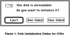 Figure 1–Disk Initialization Dialog for IOErr
Note: Before presenting the disk initialization dialog, DIBadMount checks
whether the drive contains an already mounted volume; if so, it ejects
the disk and returns 2 as its result. This will happen rarely and may
reflect an error in your program (for example, you forgot to call
DILoad and the user had to switch to the disk containing the system
resource file).
If the user responds to the disk initialization dialog by clicking the Eject button, DIBadMount ejects the disk and returns 1 as its result. If the Initialize button is clicked, a box displaying the message “Initializing
disk...” appears, and DIBadMount attempts to initialize the disk. If initialization fails, the disk is ejected and the user is informed as shown in Figure 2; after the user clicks OK, DIBadMount returns a negative result code ranging from firstDskErr to lastDskErr, indicating that a low-level disk error occurred.
Figure 1–Disk Initialization Dialog for IOErr
Note: Before presenting the disk initialization dialog, DIBadMount checks
whether the drive contains an already mounted volume; if so, it ejects
the disk and returns 2 as its result. This will happen rarely and may
reflect an error in your program (for example, you forgot to call
DILoad and the user had to switch to the disk containing the system
resource file).
If the user responds to the disk initialization dialog by clicking the Eject button, DIBadMount ejects the disk and returns 1 as its result. If the Initialize button is clicked, a box displaying the message “Initializing
disk...” appears, and DIBadMount attempts to initialize the disk. If initialization fails, the disk is ejected and the user is informed as shown in Figure 2; after the user clicks OK, DIBadMount returns a negative result code ranging from firstDskErr to lastDskErr, indicating that a low-level disk error occurred.
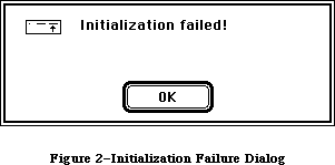 Figure 2–Initialization Failure Dialog
If the disk is successfully initialized, the dialog box in Figure 3 appears. After the user names the disk and clicks OK, DIBadMount mounts the volume by calling the File Manager function MountVol and returns MountVol’s result code
(noErr if no error occurs).
Figure 2–Initialization Failure Dialog
If the disk is successfully initialized, the dialog box in Figure 3 appears. After the user names the disk and clicks OK, DIBadMount mounts the volume by calling the File Manager function MountVol and returns MountVol’s result code
(noErr if no error occurs).
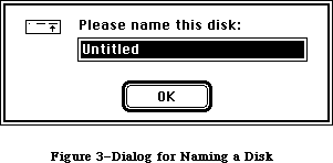 Figure 3–Dialog for Naming a Disk
Result codes noErr No error
extFSErr External file system
memFullErr Not enough room in heap zone
nsDrvErr No such drive
paramErr Bad drive number
volOnLinErr Volume already on-line
firstDskErr Low-level disk error
through lastDskErr
Other results 1 User clicked Eject
2 Mounted volume in drive
FUNCTION DIFormat (drvNum: INTEGER) : OSErr;
DIFormat formats the disk in the drive specified by the given drive number and returns a result code indicating whether the formatting was completed successfully or failed. Formatting a disk consists of writing special information onto it so that the Disk Driver can read from and write to the disk.
Result codes noErr No error
firstDskErr Low-level disk error
through lastDskErr
FUNCTION DIVerify (drvNum: INTEGER) : OSErr;
DIVerify verifies the format of the disk in the drive specified by the given drive number; it reads each bit from the disk and returns a result code indicating whether all bits were read successfully or not. DIVerify doesn’t affect the contents of the disk itself.
Result codes noErr No error
firstDskErr Low-level disk error
through lastDskErr
FUNCTION DIZero (drvNum: INTEGER; volName: Str255) : OSErr;
On the unmounted volume in the drive specified by the given drive number, DIZero writes the volume information, a block map, and a file directory as for a volume with no files; the volName parameter specifies the volume name to be included in the volume information. This is the last step in initialization
(after formatting and verifying) and makes any files that are already on the volume permanently inaccessible. If the operation fails, DIZero returns a result code indicating that a low-level disk error occurred; otherwise, it mounts the volume by calling the File Manager function MountVol and returns MountVol’s result code (noErr if no error occurs).
Result codes noErr No error
badMDBErr Bad master directory block
extFSErr External file system
ioErr I/O error
memFullErr Not enough room in heap zone
noMacDskErr Not a Macintosh disk
nsDrvErr No such drive
paramErr Bad drive number
volOnLinErr Volume already on-line
firstDskErr Low-level disk error
through lastDskErr
_______________________________________________________________________________
»SUMMARY OF THE DISK INITIALIZATION PACKAGE
_______________________________________________________________________________
Routines
PROCEDURE DILoad;
PROCEDURE DIUnload;
FUNCTION DIBadMount (where: Point; evtMessage: LONGINT) : INTEGER;
FUNCTION DIFormat (drvNum: INTEGER) : OSErr;
FUNCTION DIVerify (drvNum: INTEGER) : OSErr;
FUNCTION DIZero (drvNum: INTEGER; volName: Str255) : OSErr;
_______________________________________________________________________________
Result Codes
Name Value Meaning
badMDBErr –60 Bad master directory block
extFSErr –58 External file system
firstDskErr –84 First of the range of low-level disk errors
ioErr –36 I/O error
lastDskErr –64 Last of the range of low-level disk errors
memFullErr –108 Not enough room in heap zone
noErr 0 No error
noMacDskErr –57 Not a Macintosh disk
nsDrvErr –56 No such drive
paramErr –50 Bad drive number
volOnLinErr –55 Volume already on-line
_______________________________________________________________________________
Assembly-Language Information
Constants
; Routine selectors
diBadMount .EQU 0
diLoad .EQU 2
diUnload .EQU 4
diFormat .EQU 6
diVerify .EQU 8
diZero .EQU 10
Variables
FmtDefaults Pointer to substitute values for
hierarchical volume characteristics [128K ROM]
Trap Macro Name
_Pack2
Further Reference:
_______________________________________________________________________________
QuickDraw
Toolbox Event Manager
File Manager
Package Manager
Standard File Package
Disk Driver
Technical Note #70, Forcing Disks to be Either 400K or 800K
“Macintosh Family Hardware Reference”
Figure 3–Dialog for Naming a Disk
Result codes noErr No error
extFSErr External file system
memFullErr Not enough room in heap zone
nsDrvErr No such drive
paramErr Bad drive number
volOnLinErr Volume already on-line
firstDskErr Low-level disk error
through lastDskErr
Other results 1 User clicked Eject
2 Mounted volume in drive
FUNCTION DIFormat (drvNum: INTEGER) : OSErr;
DIFormat formats the disk in the drive specified by the given drive number and returns a result code indicating whether the formatting was completed successfully or failed. Formatting a disk consists of writing special information onto it so that the Disk Driver can read from and write to the disk.
Result codes noErr No error
firstDskErr Low-level disk error
through lastDskErr
FUNCTION DIVerify (drvNum: INTEGER) : OSErr;
DIVerify verifies the format of the disk in the drive specified by the given drive number; it reads each bit from the disk and returns a result code indicating whether all bits were read successfully or not. DIVerify doesn’t affect the contents of the disk itself.
Result codes noErr No error
firstDskErr Low-level disk error
through lastDskErr
FUNCTION DIZero (drvNum: INTEGER; volName: Str255) : OSErr;
On the unmounted volume in the drive specified by the given drive number, DIZero writes the volume information, a block map, and a file directory as for a volume with no files; the volName parameter specifies the volume name to be included in the volume information. This is the last step in initialization
(after formatting and verifying) and makes any files that are already on the volume permanently inaccessible. If the operation fails, DIZero returns a result code indicating that a low-level disk error occurred; otherwise, it mounts the volume by calling the File Manager function MountVol and returns MountVol’s result code (noErr if no error occurs).
Result codes noErr No error
badMDBErr Bad master directory block
extFSErr External file system
ioErr I/O error
memFullErr Not enough room in heap zone
noMacDskErr Not a Macintosh disk
nsDrvErr No such drive
paramErr Bad drive number
volOnLinErr Volume already on-line
firstDskErr Low-level disk error
through lastDskErr
_______________________________________________________________________________
»SUMMARY OF THE DISK INITIALIZATION PACKAGE
_______________________________________________________________________________
Routines
PROCEDURE DILoad;
PROCEDURE DIUnload;
FUNCTION DIBadMount (where: Point; evtMessage: LONGINT) : INTEGER;
FUNCTION DIFormat (drvNum: INTEGER) : OSErr;
FUNCTION DIVerify (drvNum: INTEGER) : OSErr;
FUNCTION DIZero (drvNum: INTEGER; volName: Str255) : OSErr;
_______________________________________________________________________________
Result Codes
Name Value Meaning
badMDBErr –60 Bad master directory block
extFSErr –58 External file system
firstDskErr –84 First of the range of low-level disk errors
ioErr –36 I/O error
lastDskErr –64 Last of the range of low-level disk errors
memFullErr –108 Not enough room in heap zone
noErr 0 No error
noMacDskErr –57 Not a Macintosh disk
nsDrvErr –56 No such drive
paramErr –50 Bad drive number
volOnLinErr –55 Volume already on-line
_______________________________________________________________________________
Assembly-Language Information
Constants
; Routine selectors
diBadMount .EQU 0
diLoad .EQU 2
diUnload .EQU 4
diFormat .EQU 6
diVerify .EQU 8
diZero .EQU 10
Variables
FmtDefaults Pointer to substitute values for
hierarchical volume characteristics [128K ROM]
Trap Macro Name
_Pack2
Further Reference:
_______________________________________________________________________________
QuickDraw
Toolbox Event Manager
File Manager
Package Manager
Standard File Package
Disk Driver
Technical Note #70, Forcing Disks to be Either 400K or 800K
“Macintosh Family Hardware Reference”
The File Manager
_______________________________________________________________________________
THE FILE MANAGER
_______________________________________________________________________________
About This Chapter
About the File Manager
Volumes and the File Directory
About Names
About Directories
About Volumes
About Files
Overview of the New File Access Methods
Opening Files
Browsing
Exclusive Access
Single Writer, Multiple Readers
Shared Access
Translation of Permissions
The Shared Environment
AppleShare
Resource Availability
Sharing
Range Locking
Sharing Applications
Shared Environment Guidelines
Things to Do
Things to Avoid
Using the File Manager
Hierarchical Routines
Working Directories
Pathnames
Specifying Volumes, Directories, and Files
Indexing
Accessing Files
Accessing Volumes
Advanced Routines
The Shared Environment Calls
HFS Support
Error Reporting
Data Structures
Information Used by the Finder
Flat Volumes
Hierarchical Volumes
High-Level File Manager Routines
Accessing Volumes
Accessing Files
Creating and Deleting Files
Changing Information About Files
Low-Level File Manager Routines
Parameter Blocks
IOParam Variant (ParamBlockRec and HParamBlockRec)
FileParam Variant (ParamBlockRec and HParamBlockRec)
VolumeParam Variant (ParamBlockRec)
VolumeParam Variant (HParamBlockRec)
CInfoPBRec
CMovePBRec
WDPBRec
Routine Descriptions
Initializing the File I/O Queue
Accessing Volumes
Accessing Files
Creating and Deleting Files and Directories
Changing Information About Files and Directories
Hierarchical Directory Routines
Working Directory Routines
Shared Volume HFS Routines
Data Organization on Volumes
Flat Directory Volumes
Volume Information
Volume Allocation Block Map
Flat File Directory
Hierarchical Directory Volumes
Volume Information
Volume Bit Map
B*-Trees
Extents Tree File
Catalog Tree File
Data Structures in Memory
The File I/O Queue
Volume Control Blocks
File Control Blocks
The Drive Queue
Using an External File System
Summary of the File Manager
_______________________________________________________________________________
»ABOUT THIS CHAPTER
_______________________________________________________________________________
This chapter describes the File Manager, the part of the Operating System that controls the exchange of information between a Macintosh application and files. The File Manager allows you to create and access any number of files containing whatever information you choose.
The changes to the File Manager are so extensive that the chapter has been completely rewritten. For most programmers, the changes are transparent and require no modification of code. All operations on the 64K ROM version of the File Manager are supported.
This chapter also presents a set of new file access routines that support application execution in a shared environment. A shared environment can mean a number of workstations connected to a file server; it can also mean a multitasking operating system or a system program that allows sharing applications or data. The discussion in this chapter focuses on AppleShare™. This chapter describes how the old access modes are translated into the new ones, discusses some aspects of file access implementation in a shared environment, and presents the format of the routines.
Reader’s guide: Since virtually any application may someday find itself
executing in a shared environment, all developers should
have some understanding of the information in this chapter.
Readers should be familiar with the following chapters from
Inside Macintosh:
• The AppleTalk Manager
• The Device Manager
• The Standard File Package
Further information on Apple networking and file servers may be obtained from
• Inside AppleTalk, Section XI: AppleTalk Session Protocol (ASP)
• AppleTalk Filing Protocol, Version 1.1
• AppleShare User’s Guide
• AppleShare Administrator’s Guide
• AppleTalk Filing Protocol Engineering Notes
_______________________________________________________________________________
»ABOUT THE FILE MANAGER
_______________________________________________________________________________
The File Manager is the part of the Operating System that handles communication between an application and files on block devices such as disk drives. (Block devices are discussed in the Device Manager chapter.) Files are a principal means by which data is stored and transmitted on the Macintosh. A file is a named, ordered sequence of bytes. The File Manager contains routines used to read from and write to files.
Warning: Currently, only a startup volume with the AppleShare file located
in its System Folder supports the File Manager extensions. Future
versions of the File Manager may or may not support these calls.
When the File Manager was originally designed, only three file-access modes were thought to be necessary: read/write, read only, and whatever’s available
(of the first two). These modes operated under a basic rule of file access known as “single writer and/or multiple readers”. In a world with file servers and multitasking systems, where more than one application might have access to a document simultaneously, this rule and these access modes are not sufficiently flexible.
In addition to specifying the access required by the caller, the new access modes give the caller the ability to deny access to other users. The new modes are therefore known as deny modes. They operate by setting bits in the permissions byte instead of using a constant value as a message. The new access modes are implemented by ten new calls and one modified call (PBGetCatInfo) described later in this chapter.
So that existing applications will work, the external file system used by AppleShare translates the old modes into the new. For the majority of applications, this translation will be sufficient.
_______________________________________________________________________________
»Volumes and the File Directory
A volume is a piece of storage medium, such as a disk, formatted to contain files. A volume can be an entire disk or only part of a disk. A 3 1/2-inch Macintosh disk is one volume. Specialized memory devices, such as hard disks and file servers, can contain many volumes. The size of a volume also varies from one type of device to another. Macintosh volumes are formatted into chunks known as logical blocks, each able to contain up to 512 bytes. Files are stored in allocation blocks, which are multiples of logical blocks.
Each volume has a file directory containing information about the files on the volume. With small volumes (containing only a few dozen files), a “flat” file directory organized as a simple, unsorted list of file names is sufficient. Volumes initialized by the 64K ROM have such a flat file directory.
64K ROM note: The 128K ROM version of the File Manager supports all
operations on flat file directories.
With the introduction of larger storage devices (several megabytes per volume) containing a large number of files (thousands per volume), the flat file directory proves inadequate, since an exhaustive, linear search of all the files is so time-consuming. A major feature of the 128K ROM version of the File Manager is the implementation of a hierarchical file directory (sometimes referred to as the file catalog), that significantly speeds up access to large volumes.
The hierarchical file directory allows a volume to be divided into smaller units known as directories. Directories can contain files as well as other directories. Directories contained within directories are also known as subdirectories.
The hierarchical directory structure is equivalent to the user’s perceived desktop hierarchy, where folders contain files or additional folders. In the 64K ROM version of the File Manager, however, this desktop hierarchy was essentially an illusion maintained completely by the Finder (at considerable expense). The introduction of an actual hierarchical directory containing subdirectories greatly enhances the performance of the Finder by relieving it of this task.
Figure 1 illustrates these two ways of organizing the files on a volume.
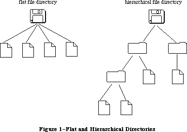 Figure 1–Flat and Hierarchical Directories
_______________________________________________________________________________
»About Names
Volumes, directories, and files all have names. A volume name consists of any sequence of 1 to 27 printing characters, excluding colons (:). File names and directory names consist of any sequence of 1 to 31 printing characters, excluding colons. You can use uppercase and lowercase letters when naming things, but the File Manager ignores case when comparing names (it doesn’t ignore diacritical marks).
64K ROM note: The 64K ROM version of the File Manager allows file names
of up to 255 characters. File names should be constrained
to 31 characters, however, to maintain compatibility with
the 128K ROM version of the File Manager. The 64K ROM version
of the File Manager also allows the specification of a
version number to distinguish between different files with
the same name. Version numbers are generally set to 0, though,
because the Resource Manager, Segment Loader, and Standard
File Package won’t operate on files with nonzero version
numbers, and the Finder ignores version numbers.
_______________________________________________________________________________
»About Directories
A few terms are needed to describe the relationships between directories on a hierarchical volume. Figure 2 shows what looks to be an upside-down tree; it’s a sample hierarchical volume.
Figure 1–Flat and Hierarchical Directories
_______________________________________________________________________________
»About Names
Volumes, directories, and files all have names. A volume name consists of any sequence of 1 to 27 printing characters, excluding colons (:). File names and directory names consist of any sequence of 1 to 31 printing characters, excluding colons. You can use uppercase and lowercase letters when naming things, but the File Manager ignores case when comparing names (it doesn’t ignore diacritical marks).
64K ROM note: The 64K ROM version of the File Manager allows file names
of up to 255 characters. File names should be constrained
to 31 characters, however, to maintain compatibility with
the 128K ROM version of the File Manager. The 64K ROM version
of the File Manager also allows the specification of a
version number to distinguish between different files with
the same name. Version numbers are generally set to 0, though,
because the Resource Manager, Segment Loader, and Standard
File Package won’t operate on files with nonzero version
numbers, and the Finder ignores version numbers.
_______________________________________________________________________________
»About Directories
A few terms are needed to describe the relationships between directories on a hierarchical volume. Figure 2 shows what looks to be an upside-down tree; it’s a sample hierarchical volume.
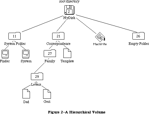 Figure 2–A Hierarchical Volume
X-Ref: Technical Note #77
X-Ref: Technical Note #102
All of the volume’s files stem from the directory labeled MyDisk; this is the root directory and is none other than the volume itself. The name of the root directory of a volume is the same as the volume name.
Note: The volume name, constrained to 27 characters, is the sole exception
to the rule that directory names can be up to 31 characters long.
Each directory, including the root directory, is a distinct, addressable entity. Each directory has its own set of offspring (possibly an empty set), which is those files or directories contained in it. For instance, the directory Letters has the files Dad and Geri as offspring, while the root directory contains the file MacWrite and the directories System Folder and Empty Folder. Borrowing a term from physics, the number of offspring is known as the directory’s valence; for instance, the valence of the directory Correspondence is 2. Similarly, for a given file or directory, the directory immediately above it is known as its parent. The root directory is the only directory that doesn’t have a parent.
When created, every directory is given a directory ID that’s unique (and assigned sequentially) for any given volume. The root directory always has a directory ID of 2. In Figure 2, for instance, the directory Empty Folder has a directory ID of 26. The directory ID of a given offspring’s parent is known as its parent ID; for example, the parent ID of the file Template is 21.
_______________________________________________________________________________
»About Volumes
A volume can be mounted or unmounted. When a volume is mounted, the File Manager reads descriptive information about the volume into memory. For each mounted volume, part of this information is placed in a data structure known as a volume control block (described in detail in the section “Data Structures in Memory”).
Ejectable volumes (such as the 3 1/2-inch disks) are mounted when they’re inserted into a disk drive; nonejectable volumes (such as those on hard disks) are always mounted. Only mounted volumes are known to the File Manager, and an application can access information on mounted volumes only. When a volume is unmounted, the File Manager releases the information stored in the volume control block.
A mounted volume can be on-line or off-line. A mounted volume is on-line as long as the volume buffer and all the descriptive information read from the volume when it was mounted remain in memory (about 1K to 1.5K bytes); it becomes off-line when all but the volume control block is released. You can access information on on-line volumes immediately, but off-line volumes must be placed on-line before their information can be accessed. When an application ejects a 3 1/2-inch disk from a drive, the File Manager automatically places the volume off-line. Whenever the File Manager needs to access a mounted volume that’s been placed off-line and ejected, the dialog box shown in Figure 3 is displayed, and the File Manager waits until the user inserts the disk named volName into a drive.
Figure 2–A Hierarchical Volume
X-Ref: Technical Note #77
X-Ref: Technical Note #102
All of the volume’s files stem from the directory labeled MyDisk; this is the root directory and is none other than the volume itself. The name of the root directory of a volume is the same as the volume name.
Note: The volume name, constrained to 27 characters, is the sole exception
to the rule that directory names can be up to 31 characters long.
Each directory, including the root directory, is a distinct, addressable entity. Each directory has its own set of offspring (possibly an empty set), which is those files or directories contained in it. For instance, the directory Letters has the files Dad and Geri as offspring, while the root directory contains the file MacWrite and the directories System Folder and Empty Folder. Borrowing a term from physics, the number of offspring is known as the directory’s valence; for instance, the valence of the directory Correspondence is 2. Similarly, for a given file or directory, the directory immediately above it is known as its parent. The root directory is the only directory that doesn’t have a parent.
When created, every directory is given a directory ID that’s unique (and assigned sequentially) for any given volume. The root directory always has a directory ID of 2. In Figure 2, for instance, the directory Empty Folder has a directory ID of 26. The directory ID of a given offspring’s parent is known as its parent ID; for example, the parent ID of the file Template is 21.
_______________________________________________________________________________
»About Volumes
A volume can be mounted or unmounted. When a volume is mounted, the File Manager reads descriptive information about the volume into memory. For each mounted volume, part of this information is placed in a data structure known as a volume control block (described in detail in the section “Data Structures in Memory”).
Ejectable volumes (such as the 3 1/2-inch disks) are mounted when they’re inserted into a disk drive; nonejectable volumes (such as those on hard disks) are always mounted. Only mounted volumes are known to the File Manager, and an application can access information on mounted volumes only. When a volume is unmounted, the File Manager releases the information stored in the volume control block.
A mounted volume can be on-line or off-line. A mounted volume is on-line as long as the volume buffer and all the descriptive information read from the volume when it was mounted remain in memory (about 1K to 1.5K bytes); it becomes off-line when all but the volume control block is released. You can access information on on-line volumes immediately, but off-line volumes must be placed on-line before their information can be accessed. When an application ejects a 3 1/2-inch disk from a drive, the File Manager automatically places the volume off-line. Whenever the File Manager needs to access a mounted volume that’s been placed off-line and ejected, the dialog box shown in Figure 3 is displayed, and the File Manager waits until the user inserts the disk named volName into a drive.
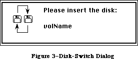 Figure 3–Disk-Switch Dialog
Note: This dialog is actually a system error alert, as described in
the System Error Handler chapter.
Mounted volumes share a common set of volume buffers, which is temporary storage space in the heap used when reading or writing information on the volume. The number of volumes that may be mounted at any time is limited only by the number of drives attached and available memory.
64K ROM note: In the 64K ROM version of the File Manager, each mounted
volume was assigned its own volume buffer.
To prevent unauthorized writing to a volume, volumes can be locked. Locking a volume involves either setting a software flag on the volume or changing some part of the volume physically (for example, sliding a tab from one position to another on a 3 1/2-inch disk). Locking a volume ensures that none of the data on the volume can be changed.
Each volume has a name that you can use to identify it. On-line volumes in disk drives can also be accessed via the drive number of the drive on which the volume is mounted; the internal drive is number 1, the external drive is number 2, and any additional drives connected to the Macintosh will have larger numbers. In most routines, however, you’ll identify a volume by its volume reference number, which is assigned to a volume when it’s mounted. When accessing an on-line volume, you should always use the volume reference number or the volume name rather than a drive number, because the volume may have been ejected or placed off-line. Whenever possible, use the volume reference number
(to avoid confusion between volumes with the same name).
Note: In the case of specialized storage devices (such as hard disks)
containing several volumes, only the first on-line volume can be
accessed using the drive number of the device.
_______________________________________________________________________________
»About Files
A file is a finite sequence of numbered bytes. Any byte or group of bytes in the sequence can be accessed individually. A byte within a file is identified by its position within the ordered sequence.
There are two parts, or forks, to a file: the data fork and the resource fork. Normally the resource fork of an application file contains the resources used by the application, such as menus, fonts, and icons, and also the application code itself. The data fork can contain anything an application wants to store there. Information stored in resource forks should always be accessed via the Resource Manager. Information in data forks can only be accessed via the File Manager. For simplicity, “file” will be used instead of “data fork” in this chapter.
The size of a file is limited only by the size of the volume it’s on. Space is allocated to a file in allocation blocks (multiples of 512 bytes). Two numbers are used to describe the size of a file. The physical end-of-file is the number of bytes currently allocated to the file; it’s 1 greater than the number of the last byte in its last allocation block (since the first byte is byte number 0). The logical end-of-file is the number of those allocated bytes that currently contain data; it’s 1 greater than the number of the last byte in the file that contains data. For example, given an allocation block size of two logical blocks (that is, 1024 bytes), a file with 50 bytes of data has a logical
end-of-file of 50 and a physical end-of-file of 1024 (see Figure 4).
Figure 3–Disk-Switch Dialog
Note: This dialog is actually a system error alert, as described in
the System Error Handler chapter.
Mounted volumes share a common set of volume buffers, which is temporary storage space in the heap used when reading or writing information on the volume. The number of volumes that may be mounted at any time is limited only by the number of drives attached and available memory.
64K ROM note: In the 64K ROM version of the File Manager, each mounted
volume was assigned its own volume buffer.
To prevent unauthorized writing to a volume, volumes can be locked. Locking a volume involves either setting a software flag on the volume or changing some part of the volume physically (for example, sliding a tab from one position to another on a 3 1/2-inch disk). Locking a volume ensures that none of the data on the volume can be changed.
Each volume has a name that you can use to identify it. On-line volumes in disk drives can also be accessed via the drive number of the drive on which the volume is mounted; the internal drive is number 1, the external drive is number 2, and any additional drives connected to the Macintosh will have larger numbers. In most routines, however, you’ll identify a volume by its volume reference number, which is assigned to a volume when it’s mounted. When accessing an on-line volume, you should always use the volume reference number or the volume name rather than a drive number, because the volume may have been ejected or placed off-line. Whenever possible, use the volume reference number
(to avoid confusion between volumes with the same name).
Note: In the case of specialized storage devices (such as hard disks)
containing several volumes, only the first on-line volume can be
accessed using the drive number of the device.
_______________________________________________________________________________
»About Files
A file is a finite sequence of numbered bytes. Any byte or group of bytes in the sequence can be accessed individually. A byte within a file is identified by its position within the ordered sequence.
There are two parts, or forks, to a file: the data fork and the resource fork. Normally the resource fork of an application file contains the resources used by the application, such as menus, fonts, and icons, and also the application code itself. The data fork can contain anything an application wants to store there. Information stored in resource forks should always be accessed via the Resource Manager. Information in data forks can only be accessed via the File Manager. For simplicity, “file” will be used instead of “data fork” in this chapter.
The size of a file is limited only by the size of the volume it’s on. Space is allocated to a file in allocation blocks (multiples of 512 bytes). Two numbers are used to describe the size of a file. The physical end-of-file is the number of bytes currently allocated to the file; it’s 1 greater than the number of the last byte in its last allocation block (since the first byte is byte number 0). The logical end-of-file is the number of those allocated bytes that currently contain data; it’s 1 greater than the number of the last byte in the file that contains data. For example, given an allocation block size of two logical blocks (that is, 1024 bytes), a file with 50 bytes of data has a logical
end-of-file of 50 and a physical end-of-file of 1024 (see Figure 4).
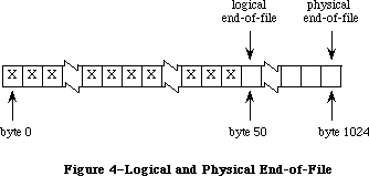 Figure 4–Logical and Physical End-of-File
The File Manager maintains a current position marker, called the mark, to keep track of where it is in the file during a read or write operation. The mark is the number of the next byte that will be read or written; each time a byte is read or written, the mark is moved.
When, during a write operation, the mark reaches the number of the last byte currently allocated to the file, another allocation block is added to the file.
You can read bytes from and write bytes to a file either singly or in sequences of unlimited length. You can specify where each read or write operation should begin by setting the mark; if you don’t, the operation begins at the byte where the mark currently points. You can find the current position of the mark by calling GetFPos. You can set the mark before the read or write operation with SetFPos; you can also set it in the Read or Write call itself.
You can move the logical end-of-file to adjust the size of the file (such as after a resource file has been compacted); when the logical end-of-file is moved to a position more than one allocation block short of the current physical end-of-file, the unneeded allocation block will be deleted from the file. You can also increase the size of a file by moving the logical-end-file past the physical end-of-file.
A file can be open or closed. An application can perform only certain operations, such as reading and writing, on open files; other operations, such as deleting, can be performed only on closed files.
Your application can lock a file to prevent unauthorized writing to it. Locking a file ensures that none of the data in it can be changed; this is the same as the user-accessible lock maintained by the Finder.
When a file is opened, the File Manager reads useful information about the file from its volume and stores it in a data structure known as a file control block. The contents of the file control block (described in detail in the section
“Data Structures in Memory”) are used frequently and can be obtained with the function GetFileInfo.
When a file is opened, the File Manager creates an access path, a description of the route to be followed when accessing the file. The access path specifies the volume on which the file is located and the location of the file on the volume. Every access path is assigned a unique path reference number (a number greater than 0) that’s used to refer to it. A file can have multiple access paths open; each access path is separate from all other access paths to the file.
Each file has open permission information, which indicates whether data can be written to it or not. When you open a file, you request permission to read or write via an access path. You can request permission to read only, write only
(rarely done), or both read and write. There are two types of read/write permission—exclusive and shared. Applications will generally want to request exclusive read/write permission. If an access path requests and is granted exclusive read/write permission, no other access path will be granted permission to write (whether write only, exclusive read/write, or shared
read/write).
A second type of read/write permission allows multiple access paths to be open for writing. If you’ll be using only a portion, or range, of a file, you can request shared read/write permission. With shared read/write permission, the application must see to it that the file’s data integrity is preserved. Before writing to a particular range of bytes, you need to “lock” it so that other access paths cannot write to that range at the same time. In the meantime, other access paths opened with shared read/write access can lock and write to other parts of the file.
The shared read/write permission has no utility on a single Macintosh; this permission is intended for, and will be passed by, external file systems, where multiple read/write operations are performed.
Note: If an access path is open with shared read/write permission,
no access path can be granted exclusive read/write access.
64K ROM note: Shared read/write permission is not implemented in the
64K ROM version of the File Manager.
If the file’s open permission doesn’t allow I/O as requested, a result code indicating the error is returned.
Each access path can move its own mark and read at the position it indicates. All access paths to the same file share common logical and physical end-of-file markers.
When an application requests that data be read from a file, the File Manager reads the data from the file and transfers it to the application’s data buffer. Any part of the data that can be transferred in entire 512-byte blocks is transferred directly. Any part of the data composed of fewer than 512 bytes is also read from the file in one 512-byte block, but placed in temporary storage space in memory. Then, only the bytes containing the requested data are transferred to the application.
When an application writes data to a file, the File Manager transfers the data from the application’s data buffer and writes it to the file. Any part of the data that can be transferred in entire 512-byte blocks is written directly. Any part of the data composed of fewer than 512 bytes is placed in temporary storage space in memory until 512 bytes have accumulated; then the entire block is written all at once.
Note: Advanced programmers: The File Manager can also read a continuous
stream of characters or a line of characters. In the first case,
you ask the File Manager to read a specific number of bytes: When
that many have been read or when the mark has reached the logical
end-of-file, the read operation terminates. In the second case,
called newline mode, the read will terminate when either of the
above conditions is met or when a specified character, the newline
character, is read. The newline character is usually Return (ASCII
code $0D), but it can be any character. Information about newline
mode is associated with each access path to a file, and can differ
from one access path to another.
Normally the temporary space in memory used for all reading and writing is the volume buffer, but an application can specify that an access path buffer be used instead for a particular access path (see Figure 5).
Figure 4–Logical and Physical End-of-File
The File Manager maintains a current position marker, called the mark, to keep track of where it is in the file during a read or write operation. The mark is the number of the next byte that will be read or written; each time a byte is read or written, the mark is moved.
When, during a write operation, the mark reaches the number of the last byte currently allocated to the file, another allocation block is added to the file.
You can read bytes from and write bytes to a file either singly or in sequences of unlimited length. You can specify where each read or write operation should begin by setting the mark; if you don’t, the operation begins at the byte where the mark currently points. You can find the current position of the mark by calling GetFPos. You can set the mark before the read or write operation with SetFPos; you can also set it in the Read or Write call itself.
You can move the logical end-of-file to adjust the size of the file (such as after a resource file has been compacted); when the logical end-of-file is moved to a position more than one allocation block short of the current physical end-of-file, the unneeded allocation block will be deleted from the file. You can also increase the size of a file by moving the logical-end-file past the physical end-of-file.
A file can be open or closed. An application can perform only certain operations, such as reading and writing, on open files; other operations, such as deleting, can be performed only on closed files.
Your application can lock a file to prevent unauthorized writing to it. Locking a file ensures that none of the data in it can be changed; this is the same as the user-accessible lock maintained by the Finder.
When a file is opened, the File Manager reads useful information about the file from its volume and stores it in a data structure known as a file control block. The contents of the file control block (described in detail in the section
“Data Structures in Memory”) are used frequently and can be obtained with the function GetFileInfo.
When a file is opened, the File Manager creates an access path, a description of the route to be followed when accessing the file. The access path specifies the volume on which the file is located and the location of the file on the volume. Every access path is assigned a unique path reference number (a number greater than 0) that’s used to refer to it. A file can have multiple access paths open; each access path is separate from all other access paths to the file.
Each file has open permission information, which indicates whether data can be written to it or not. When you open a file, you request permission to read or write via an access path. You can request permission to read only, write only
(rarely done), or both read and write. There are two types of read/write permission—exclusive and shared. Applications will generally want to request exclusive read/write permission. If an access path requests and is granted exclusive read/write permission, no other access path will be granted permission to write (whether write only, exclusive read/write, or shared
read/write).
A second type of read/write permission allows multiple access paths to be open for writing. If you’ll be using only a portion, or range, of a file, you can request shared read/write permission. With shared read/write permission, the application must see to it that the file’s data integrity is preserved. Before writing to a particular range of bytes, you need to “lock” it so that other access paths cannot write to that range at the same time. In the meantime, other access paths opened with shared read/write access can lock and write to other parts of the file.
The shared read/write permission has no utility on a single Macintosh; this permission is intended for, and will be passed by, external file systems, where multiple read/write operations are performed.
Note: If an access path is open with shared read/write permission,
no access path can be granted exclusive read/write access.
64K ROM note: Shared read/write permission is not implemented in the
64K ROM version of the File Manager.
If the file’s open permission doesn’t allow I/O as requested, a result code indicating the error is returned.
Each access path can move its own mark and read at the position it indicates. All access paths to the same file share common logical and physical end-of-file markers.
When an application requests that data be read from a file, the File Manager reads the data from the file and transfers it to the application’s data buffer. Any part of the data that can be transferred in entire 512-byte blocks is transferred directly. Any part of the data composed of fewer than 512 bytes is also read from the file in one 512-byte block, but placed in temporary storage space in memory. Then, only the bytes containing the requested data are transferred to the application.
When an application writes data to a file, the File Manager transfers the data from the application’s data buffer and writes it to the file. Any part of the data that can be transferred in entire 512-byte blocks is written directly. Any part of the data composed of fewer than 512 bytes is placed in temporary storage space in memory until 512 bytes have accumulated; then the entire block is written all at once.
Note: Advanced programmers: The File Manager can also read a continuous
stream of characters or a line of characters. In the first case,
you ask the File Manager to read a specific number of bytes: When
that many have been read or when the mark has reached the logical
end-of-file, the read operation terminates. In the second case,
called newline mode, the read will terminate when either of the
above conditions is met or when a specified character, the newline
character, is read. The newline character is usually Return (ASCII
code $0D), but it can be any character. Information about newline
mode is associated with each access path to a file, and can differ
from one access path to another.
Normally the temporary space in memory used for all reading and writing is the volume buffer, but an application can specify that an access path buffer be used instead for a particular access path (see Figure 5).
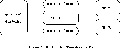 Figure 5–Buffers for Transferring Data
Warning: You must lock any access path buffers of files in relocatable
blocks, so their location doesn’t change while the file is open.
_______________________________________________________________________________
»OVERVIEW OF THE NEW FILE ACCESS METHODS
_______________________________________________________________________________
This overview first describes the new access modes and how they might be used, and then how the old permissions are translated into the new.
_______________________________________________________________________________
»Opening Files
The combination of access and deny requests in the new open calls creates four opening possibilities: browsing, exclusive access, single writer with multiple readers, and multiple writers. The best way to open a file depends on how the application is going to use it. Figure 6 charts the opening possibilities, including whether range locking is needed. (Range locking is described later in this chapter.)
Figure 5–Buffers for Transferring Data
Warning: You must lock any access path buffers of files in relocatable
blocks, so their location doesn’t change while the file is open.
_______________________________________________________________________________
»OVERVIEW OF THE NEW FILE ACCESS METHODS
_______________________________________________________________________________
This overview first describes the new access modes and how they might be used, and then how the old permissions are translated into the new.
_______________________________________________________________________________
»Opening Files
The combination of access and deny requests in the new open calls creates four opening possibilities: browsing, exclusive access, single writer with multiple readers, and multiple writers. The best way to open a file depends on how the application is going to use it. Figure 6 charts the opening possibilities, including whether range locking is needed. (Range locking is described later in this chapter.)
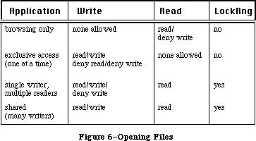 Figure 6–Opening Files
»Browsing
Browsing is traditional read-only access. Browsing access permits multiple readers but no writers. Browsing access is useful for common files, such as help files, configuration files that don’t often change, and dictionaries. Developers may wish to add a “Browse Only” checkbox to the SFGetFile dialog, so that the user may explicitly open a file in this manner.
Note that the new deny flags take into account both existing access paths to a file and future attempts to open new paths. For example, if you attempt to open a file for browsing (read/deny-write permission), your call will succeed only if no write access paths currently exist to the file. Also, all future attempts to open the file with write access will fail (with a message that you already have a read/deny-write path) until you close the first read/deny-write path.
»Exclusive Access
This is the access mode that most unshared-data applications will use. (Most existing applications use fsCurPerm permissions, which are translated to exclusive access if it’s available, as described below.) An exclusive-access open call will succeed only if there are no existing paths to the file. All future attempts to establish access paths to the file will be denied until the exclusive-access path is closed.
AppleShare note: an exclusive-access open call will fail if you try to
open a path to a file in a folder to which you do not
have both “see files” and “make changes” privileges.
In such a case, you could offer the user the choice of
opening a browse-only copy of the file, and try again
using browsing access. Or you could attempt browsing
access as soon as exclusive access fails, to avoid
offering a choice that won’t work. If the browsing
access fails, report that the file cannot be opened;
if it succeeds, offer the user the browse-only file.
»Single Writer, Multiple Readers
This access method allows additional users to gain read-only access to browse a document being modified by the initial writer. The writer’s application is responsible for range-locking the file before writing to it, to protect the readers from reading when the file is inconsistent. Likewise, the reader’s application must explicitly check for errors in reading the file, to warn the user that the file was in the process of being updated and to try again later.
Single writer, multiple readers is a step toward shared data, one that may be easy to accomplish for existing applications, especially those that are memory based. (A memory-based application is one that, when it opens a document, reads the entire document into memory. Note that it should not close the document’s file, as this could lead to checkout problems, as described below under “Network Programming Guidelines”.)
»Shared Access
Shared access should be used by an application that supports full multi-user access to its documents. Range locking is needed by each user’s application to prevent other users from accessing information undergoing change. Each user must check for and handle errors resulting from other users’ access. Some applications may prefer to use a semaphore to flag records in a document as checked out, rather than using range locking exclusively.
Shared access is usually designed into an application. It is not easy to modify an existing application to support full multi-user access to documents, except for memory-based applications, as discussed above.
_______________________________________________________________________________
»Translation of Permissions
AppleShare uses the deny-mode permissions exclusively. So that old applications will work, the external file system used by AppleShare (on each workstation) translates the classic permissions into the new permissions.
To keep applications from damaging each other’s files, the basic rule of file access (in translating permissions for AppleShare volumes) was changed to
“single writer OR multiple readers, but not both.” Because of this change, two applications cannot both have access to the same file unless both are read only; this eliminates the danger of reading from a file when it is inconsistent.
Note: This change in the basic rule currently applies only to AppleShare
volumes. Should a future version of the File Manager incorporate
this change for local volumes, then an application expecting to get
more than one path to a file (with at least one read/write) will fail.
Figure 7 shows how the classic permissions described in the File Manager are translated into the new deny-mode permissions.
Figure 6–Opening Files
»Browsing
Browsing is traditional read-only access. Browsing access permits multiple readers but no writers. Browsing access is useful for common files, such as help files, configuration files that don’t often change, and dictionaries. Developers may wish to add a “Browse Only” checkbox to the SFGetFile dialog, so that the user may explicitly open a file in this manner.
Note that the new deny flags take into account both existing access paths to a file and future attempts to open new paths. For example, if you attempt to open a file for browsing (read/deny-write permission), your call will succeed only if no write access paths currently exist to the file. Also, all future attempts to open the file with write access will fail (with a message that you already have a read/deny-write path) until you close the first read/deny-write path.
»Exclusive Access
This is the access mode that most unshared-data applications will use. (Most existing applications use fsCurPerm permissions, which are translated to exclusive access if it’s available, as described below.) An exclusive-access open call will succeed only if there are no existing paths to the file. All future attempts to establish access paths to the file will be denied until the exclusive-access path is closed.
AppleShare note: an exclusive-access open call will fail if you try to
open a path to a file in a folder to which you do not
have both “see files” and “make changes” privileges.
In such a case, you could offer the user the choice of
opening a browse-only copy of the file, and try again
using browsing access. Or you could attempt browsing
access as soon as exclusive access fails, to avoid
offering a choice that won’t work. If the browsing
access fails, report that the file cannot be opened;
if it succeeds, offer the user the browse-only file.
»Single Writer, Multiple Readers
This access method allows additional users to gain read-only access to browse a document being modified by the initial writer. The writer’s application is responsible for range-locking the file before writing to it, to protect the readers from reading when the file is inconsistent. Likewise, the reader’s application must explicitly check for errors in reading the file, to warn the user that the file was in the process of being updated and to try again later.
Single writer, multiple readers is a step toward shared data, one that may be easy to accomplish for existing applications, especially those that are memory based. (A memory-based application is one that, when it opens a document, reads the entire document into memory. Note that it should not close the document’s file, as this could lead to checkout problems, as described below under “Network Programming Guidelines”.)
»Shared Access
Shared access should be used by an application that supports full multi-user access to its documents. Range locking is needed by each user’s application to prevent other users from accessing information undergoing change. Each user must check for and handle errors resulting from other users’ access. Some applications may prefer to use a semaphore to flag records in a document as checked out, rather than using range locking exclusively.
Shared access is usually designed into an application. It is not easy to modify an existing application to support full multi-user access to documents, except for memory-based applications, as discussed above.
_______________________________________________________________________________
»Translation of Permissions
AppleShare uses the deny-mode permissions exclusively. So that old applications will work, the external file system used by AppleShare (on each workstation) translates the classic permissions into the new permissions.
To keep applications from damaging each other’s files, the basic rule of file access (in translating permissions for AppleShare volumes) was changed to
“single writer OR multiple readers, but not both.” Because of this change, two applications cannot both have access to the same file unless both are read only; this eliminates the danger of reading from a file when it is inconsistent.
Note: This change in the basic rule currently applies only to AppleShare
volumes. Should a future version of the File Manager incorporate
this change for local volumes, then an application expecting to get
more than one path to a file (with at least one read/write) will fail.
Figure 7 shows how the classic permissions described in the File Manager are translated into the new deny-mode permissions.
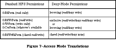 Figure 7–Access Mode Translations
FsRdPerm acts as you would expect: browsing access is achieved if there is no existing write access path to the file.
The or in the middle translations means that if the call cannot be completed successfully with exclusive access, it is automatically retried using browsing access.
For fsCurPerm, this is also what you’d expect: “whatever’s available” has always meant “read/write if you can, otherwise, read only”. The deny portions of the translation are important for enforcing the updated basic rule of file access: if there’s an existing read or write access path to a file being opened with fsCurPerm, the first set of permissions will fail; the second set, browsing access, will then succeed only if there is no existing write access path to the file.
Both fsRdWrPerm and fsWrPerm (which has always been translated into fsRdWrPerm, since write-only access has little utility) are also retried as read-only, to simulate the case where a file is being opened from a locked disk. Elsewhere, this chapter points out that fsRdWrPerm is granted even if the volume is locked, and that an error won’t be returned until a PBWrite (or SetEOF or PBAllocate) call is made. The same is now true for a read-only folder on an AppleShare volume. (An exception is that if you eject a disk, you can then write to an open file on it; changing access privileges of a folder does not change the access established for an open path to a file in that folder.)
_______________________________________________________________________________
»THE SHARED ENVIRONMENT
_______________________________________________________________________________
A file server such as AppleShare allows users to share data, applications, and disk storage over a network. A file server is a combination of a computer, special software, and one or more large-capacity disks attached to other computers via a network. In the file server context, the other computers are known as workstations. The computer network allows communication between the file server and the workstations. Users have easy access to programs, data, and disk storage provided by the file server.
_______________________________________________________________________________
»AppleShare
The server application available from Apple Computer is AppleShare. Explanation of the AppleShare file server environment should provide parallels for other shared environments.
X-Ref: Technical Note #165
X-Ref: Technical Note #216
Each hard disk attached to the server’s computer is called a file server volume. A selected server volume will appear on the workstation’s desktop as an icon and can be used just like any Macintosh disk.
Access to the information contained in folders on the disk can be controlled by use of access privileges. In the AppleShare file server environment, access privileges control who has what kind of access to the contents of the folders contained on a volume. The access privileges are assigned on a folder-by-folder basis. A folder may be kept private, shared by a group of registered users, or shared with all users on the network.
New users are registered, given passwords, and organized into groups. Users can belong to more than one group. Information about users and groups is stored in a data base on the server and is used to determine the access privileges the user or group has when they access an object on the server. The owner of a folder specifies that folder’s access privileges for the following user categories:
• Owner—the user who owns the folder (or who currently holds ownership)
• Group—any group established by the AppleShare administrator (folders
have only one group designation per folder)
• Everyone—every user who has access to the file server (registered
users and guests)
• See Folders—see other folders in the folder
• See Files—see the icons and open documents or applications in that
folder as well
• Make Changes—create, modify, rename, or delete any file or folder
contained in the particular folder (Note: folder deletion requires
other privileges as well.)
An extensive discussion of access privileges can be found in the AppleShare User’s Guide.
_______________________________________________________________________________
»Resource Availability
The availability of resources in a network or shared environment cannot be assumed. Certain file system operations taken for granted in a single-user environment must be monitored to ensure their successful completion, and appropriate error messages should be returned to the user if they fail. Some examples of failure are
• a file read or write fails because the file has been removed, the
file server has been shut down, or a break in the network has occurred
• creation of a file on the server fails due to an existing duplicate
name that is invisible to the user (it’s in a folder to which the user
does not have search access)
• a file cannot be opened for use because another user has already opened
the file or the user does not have the proper access privileges
Preflighting system operations becomes important in the shared environment. Preflighting, a term derived from the careful world of aviation, means checking the availability of a resource before you attempt to use it. For example, if an application creates temporary files, the application should check to see if the names it gives to the temporary files already exist. If the name already exists, the application can then give the temporary files other names or warn the user of the impending problem. This example is especially relevant for computers attached to a network because file storage may not be local to the computer.
_______________________________________________________________________________
»Sharing
Sharing may mean sharing both data and the application itself:
• An example of data file sharing would be a project schedule that would
be read by many users simultaneously but could be updated by only one
user at a time. Simultaneous updates to such a file must be prevented
in order to protect the data.
• An example of application file sharing would be a word processor shared
as a read only file among many users. A correctly written application,
with a proper site license, would allow many users to use the same copy
of the application at the same time.
Data files may be shared at the file or subfile level. The latter would be appropriate for applications such as data bases and spreadsheets in which several parts of the file could be updated by users simultaneously, but each part of the file can be updated by only one user at a time.
»Range Locking
Range locking is available through the PBLockRange function (_LockRng macro) described in elsewhere in this chapter. By using byte-range locking
• you can lock and unlock ranges within a file at any time while you
have it open
• you can keep other users from reading from or writing to a range
• all range locks set by you are removed automatically when you close
the file
The LockRng call locks a range of bytes in an open file opened with shared
read/write permission. Calling LockRng before writing to the file prevents another user from reading from or writing to the locked range while you are making your changes.
On a file opened with a shared read/write permission, LockRng uses the same parameter block (HParamBlockRec) as both the Read and Write calls; by calling it immediately before Read or Write, you can use the information present in the parameter block for the Read or Write call. When calling LockRng, the ioPosMode field of HParamBlockRec specifies the position mode; bits 0 and 1 indicate how to position the start of the range.
When your application finishes using the range, be sure it calls UnlockRng to free up that portion of the file for other users. Since the ioPosOffset field is modified by the Read and Write calls it must be set up again before making an UnlockRng call.
When updating a particular record and that update affects other records within the file, first determine the range of bytes affected by the updated information. Then call LockRng to lock out any other user from accessing this range of data. If the lock request succeeds, the required changes to the data can be made. Then release the lock and make the data available to other users again. If the lock fails, several retries should be done. After several unsuccessful retries, an error message could be issued to indicate that the file is busy and the user should try again later.
To append data to a file, lock a range including the logical end-of-file and the last possible addressable byte of the file ($7FFFFFFF-Hex), and then write to that range. This actually locks a range where data does not exist. Practically speaking, locking the entire unused addressable range of a file prevents another user from appending data until you unlock it.
To truncate a file, lock the entire file, truncate the data, and then unlock the file. This will prevent another user from using a portion of the file while you are in the process of truncating it.
»Sharing Applications
The shared environment may involve not only applications that allow multiple access to a file, but applications that themselves have multiple users. Some definitions may help sort this out:
• Single-user (private data) applications allow only one user at a
time to make changes to a file.
• Multi-user (shared data) applications allow two or more users to
concurrently make changes to the same file.
• Single-launch applications allow only one user at a time to launch
and use a single copy of the application.
• Multi-launch applications allow two or more users at a time to
launch and use a single copy of the application.
When single-user and multi-user are seen as describing data file sharing modes and single-launch and multi-launch describe the launching characteristic of the applications, four categories of network applications emerge, as shown in Figure 8.
Figure 7–Access Mode Translations
FsRdPerm acts as you would expect: browsing access is achieved if there is no existing write access path to the file.
The or in the middle translations means that if the call cannot be completed successfully with exclusive access, it is automatically retried using browsing access.
For fsCurPerm, this is also what you’d expect: “whatever’s available” has always meant “read/write if you can, otherwise, read only”. The deny portions of the translation are important for enforcing the updated basic rule of file access: if there’s an existing read or write access path to a file being opened with fsCurPerm, the first set of permissions will fail; the second set, browsing access, will then succeed only if there is no existing write access path to the file.
Both fsRdWrPerm and fsWrPerm (which has always been translated into fsRdWrPerm, since write-only access has little utility) are also retried as read-only, to simulate the case where a file is being opened from a locked disk. Elsewhere, this chapter points out that fsRdWrPerm is granted even if the volume is locked, and that an error won’t be returned until a PBWrite (or SetEOF or PBAllocate) call is made. The same is now true for a read-only folder on an AppleShare volume. (An exception is that if you eject a disk, you can then write to an open file on it; changing access privileges of a folder does not change the access established for an open path to a file in that folder.)
_______________________________________________________________________________
»THE SHARED ENVIRONMENT
_______________________________________________________________________________
A file server such as AppleShare allows users to share data, applications, and disk storage over a network. A file server is a combination of a computer, special software, and one or more large-capacity disks attached to other computers via a network. In the file server context, the other computers are known as workstations. The computer network allows communication between the file server and the workstations. Users have easy access to programs, data, and disk storage provided by the file server.
_______________________________________________________________________________
»AppleShare
The server application available from Apple Computer is AppleShare. Explanation of the AppleShare file server environment should provide parallels for other shared environments.
X-Ref: Technical Note #165
X-Ref: Technical Note #216
Each hard disk attached to the server’s computer is called a file server volume. A selected server volume will appear on the workstation’s desktop as an icon and can be used just like any Macintosh disk.
Access to the information contained in folders on the disk can be controlled by use of access privileges. In the AppleShare file server environment, access privileges control who has what kind of access to the contents of the folders contained on a volume. The access privileges are assigned on a folder-by-folder basis. A folder may be kept private, shared by a group of registered users, or shared with all users on the network.
New users are registered, given passwords, and organized into groups. Users can belong to more than one group. Information about users and groups is stored in a data base on the server and is used to determine the access privileges the user or group has when they access an object on the server. The owner of a folder specifies that folder’s access privileges for the following user categories:
• Owner—the user who owns the folder (or who currently holds ownership)
• Group—any group established by the AppleShare administrator (folders
have only one group designation per folder)
• Everyone—every user who has access to the file server (registered
users and guests)
• See Folders—see other folders in the folder
• See Files—see the icons and open documents or applications in that
folder as well
• Make Changes—create, modify, rename, or delete any file or folder
contained in the particular folder (Note: folder deletion requires
other privileges as well.)
An extensive discussion of access privileges can be found in the AppleShare User’s Guide.
_______________________________________________________________________________
»Resource Availability
The availability of resources in a network or shared environment cannot be assumed. Certain file system operations taken for granted in a single-user environment must be monitored to ensure their successful completion, and appropriate error messages should be returned to the user if they fail. Some examples of failure are
• a file read or write fails because the file has been removed, the
file server has been shut down, or a break in the network has occurred
• creation of a file on the server fails due to an existing duplicate
name that is invisible to the user (it’s in a folder to which the user
does not have search access)
• a file cannot be opened for use because another user has already opened
the file or the user does not have the proper access privileges
Preflighting system operations becomes important in the shared environment. Preflighting, a term derived from the careful world of aviation, means checking the availability of a resource before you attempt to use it. For example, if an application creates temporary files, the application should check to see if the names it gives to the temporary files already exist. If the name already exists, the application can then give the temporary files other names or warn the user of the impending problem. This example is especially relevant for computers attached to a network because file storage may not be local to the computer.
_______________________________________________________________________________
»Sharing
Sharing may mean sharing both data and the application itself:
• An example of data file sharing would be a project schedule that would
be read by many users simultaneously but could be updated by only one
user at a time. Simultaneous updates to such a file must be prevented
in order to protect the data.
• An example of application file sharing would be a word processor shared
as a read only file among many users. A correctly written application,
with a proper site license, would allow many users to use the same copy
of the application at the same time.
Data files may be shared at the file or subfile level. The latter would be appropriate for applications such as data bases and spreadsheets in which several parts of the file could be updated by users simultaneously, but each part of the file can be updated by only one user at a time.
»Range Locking
Range locking is available through the PBLockRange function (_LockRng macro) described in elsewhere in this chapter. By using byte-range locking
• you can lock and unlock ranges within a file at any time while you
have it open
• you can keep other users from reading from or writing to a range
• all range locks set by you are removed automatically when you close
the file
The LockRng call locks a range of bytes in an open file opened with shared
read/write permission. Calling LockRng before writing to the file prevents another user from reading from or writing to the locked range while you are making your changes.
On a file opened with a shared read/write permission, LockRng uses the same parameter block (HParamBlockRec) as both the Read and Write calls; by calling it immediately before Read or Write, you can use the information present in the parameter block for the Read or Write call. When calling LockRng, the ioPosMode field of HParamBlockRec specifies the position mode; bits 0 and 1 indicate how to position the start of the range.
When your application finishes using the range, be sure it calls UnlockRng to free up that portion of the file for other users. Since the ioPosOffset field is modified by the Read and Write calls it must be set up again before making an UnlockRng call.
When updating a particular record and that update affects other records within the file, first determine the range of bytes affected by the updated information. Then call LockRng to lock out any other user from accessing this range of data. If the lock request succeeds, the required changes to the data can be made. Then release the lock and make the data available to other users again. If the lock fails, several retries should be done. After several unsuccessful retries, an error message could be issued to indicate that the file is busy and the user should try again later.
To append data to a file, lock a range including the logical end-of-file and the last possible addressable byte of the file ($7FFFFFFF-Hex), and then write to that range. This actually locks a range where data does not exist. Practically speaking, locking the entire unused addressable range of a file prevents another user from appending data until you unlock it.
To truncate a file, lock the entire file, truncate the data, and then unlock the file. This will prevent another user from using a portion of the file while you are in the process of truncating it.
»Sharing Applications
The shared environment may involve not only applications that allow multiple access to a file, but applications that themselves have multiple users. Some definitions may help sort this out:
• Single-user (private data) applications allow only one user at a
time to make changes to a file.
• Multi-user (shared data) applications allow two or more users to
concurrently make changes to the same file.
• Single-launch applications allow only one user at a time to launch
and use a single copy of the application.
• Multi-launch applications allow two or more users at a time to
launch and use a single copy of the application.
When single-user and multi-user are seen as describing data file sharing modes and single-launch and multi-launch describe the launching characteristic of the applications, four categories of network applications emerge, as shown in Figure 8.
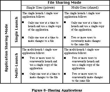 Figure 8–Sharing Applications
The multi-user application needs to
• Lock records correctly while they are being modified. Allowing and
coordinating multiple writers to a single document can be accomplished
by keeping the document open while it is in use and by using an open
mode in the file system that specifically allows subsequent users of
the document write access.
• Include an update mechanism so that all users of a document receive
updates when a record is changed.
• Use byte-range locking to permit only one writer in a byte range at
a time.
The multi-launch application needs to
• Use ResEdit or FEdit to set the multi-launch or shared bit in the
application’s finder information.
• Consider limiting the total number of concurrent users of a given
copy of the application.
Limiting the number of concurrent users requires that the application implement some method to count the users as they launch and quit the application. Counting can become complex; for example, counting temporary files is a workable approach, but the temporary files may not all be in the same place and may in fact be in the user’s boot volumes. Counting temporary files would also require checking whether or not the temporary files in existence were really in use or merely the remnants of a user crash.
One method to make things easier for the programmer is to require that a multi-launch application be able to create temporary files in the folder containing the application. You would, of course, have to document this so users would know that the application could not be launched from a read-only folder.
_______________________________________________________________________________
»Shared Environment Guidelines
This section contains some do’s and don’t’s for developers working in a network environment. Keep in mind that for most applications, the translated standard permissions will work fine.
»Things to Do
1. If using the new calls, try them first.
Structure your code such that you try the new open calls first, then
check to see if paramErr is returned. A paramErr indicates that the
file does not reside on a server volume. If that is the case, make
the equivalent old style open call. Attempts to make the new calls
specifying a local (non-AppleShare) volume will return a paramErr
indicating that the local file system does not know how to handle
the call.
2. Inform the user what access was granted during the open process.
Shared environment applications should respond appropriately to
errors returned by the file system. A more precise error reporting
mechanism is used to communicate between the file server and an
application program running in a workstation. Applications should
be prepared to respond to this error reporting mechanism correctly.
3. Use the Scrap Manager to access the Scrapbook.
Don’t implement your own scrap mechanism. Use the ROM Scrap Manager
so that resources in the scrap can be shared among applications.
4. Keep program segmentation swapping to a minimum.
The effect of program segmentation swapping is exaggerated when the
application is launched from the file server, because segments are
dynamically swapped in over the network. This can reduce the
performance of the file server.
»Things to Avoid
1. An application should not write to itself (either to data or to
resource forks).
Applications should not save information by writing into their own
file. When information specific to one user is saved in the the
application’s own file and that application is shared by two or more
users, information owned by the first user may be overwritten by the
second user, and so on.
2. Multi-user applications should not use the Resource Manager to
structure their data in a resource fork.
The Resource Manager assumes that when it reads the resource map into
memory (during OpenResFile), it will be the only one modifying that
file. If two write-access paths existed to a resource fork, neither
would have any way of notifying the other that the file had changed
(and in fact, no way to reread the map). If your application uses
resource files for document storage, you cannot share data (for
multi-user access); if you want to create a multi-user or multi-
launch version of your application you must find another way to
store your data.
3. Don’t close a file while in the process of making changes to its contents.
An application that opens a file, reads the file’s contents into memory,
and then closes the file, has checked out a copy of the file. After the
file is closed, another user can open the file, read the contents of the
file into memory, and then close it. Two copies of the file are now
checked out to two different users. Each user, after changing the
checked-out copy of the file, may decide to save the changes to the
original file: user one opens the file and writes the changes back
into the original and closes the file, then user two does the same thing.
The second user’s write operation wipes out the first. Neither user is
aware of what has happened and neither has a way of finding out.
Applications should keep the file open while in use. This will prevent
other users from obtaining an access path and modifying the file while
it’s currently open.
4. Don’t give temporary files fixed names.
Many programs that create and open temporary files give them fixed
names. If such an application is shared by many users, the program
may attempt to create temporary files with duplicate names. One
solution is not to create any temporary files on disk, holding all
information in memory. Another is to save them in the System Folder
of the user’s boot volume (startup disk) which is usually available
for the System file writing. This solution is not perfect, however,
since a person’s boot volume may be a disk with extremely limited space.
5. Do not directly examine or manipulate system data structures, such as
file control blocks (FCB) or volume control blocks (VCB), in memory.
Use File Manager calls to access FCB and VCB information.
When the application directly examines the list of data structures
related to volumes that are currently mounted without using the
appropriate calls to the File Manager, it is possible that these
structures will not accurately reflect the structure of the data on
file server volumes.
To give the file system the opportunity to update information, use
GetVolInfo to determine volume information and GetFCBInfo to determine
open file information.
6. The Allocate function is not supported by AppleShare.
Instead, use SetEOF to extend a file by setting the logical end-of-file.
_______________________________________________________________________________
»USING THE FILE MANAGER
_______________________________________________________________________________
This section outlines the routines provided by the File Manager and explains some basic concepts needed to use them. The actual routines are presented later in the chapter.
The File Manager is automatically initialized each time the system starts up.
You can call most File Manager routines via three different methods: high-level Pascal calls, low-level Pascal calls, and assembly language. The high-level Pascal calls are designed for Pascal programmers interested in using the File Manager in a simple manner; they provide adequate file I/O and don’t require much special knowledge to use. The low-level Pascal and assembly-language calls are designed for advanced Pascal programmers and assembly-language programmers interested in using the File Manager to its fullest capacity; they require some special knowledge to be used most effectively.
Note: The names used to refer to File Manager routines in text (as opposed
to in particular routine descriptions) are actually the assembly-
language macro names for the low-level routines, but the Pascal
routine names are very similar.
_______________________________________________________________________________
»Hierarchical Routines
X-Ref: Technical Note #44
X-Ref: Technical Note #77
Many new routines are introduced in the hierarchical version of the File Manager; they can be divided into two groups. These routines are used primarily by the File Manager itself.
Routines in the first group are slight extensions of certain basic File Manager routines that allow the specification of a directory ID in addition to the other parameters; in certain cases they set or obtain additional information. These specialized routines have the same names as their general-purpose counterparts, but preceded by the letter “H”. For instance, the routine HOpen is identical to the Open call except that it allows the specification of a directory ID. The routines in this first group are: HOpen, HOpenRF, HRename, HCreate, HDelete, HGetFileInfo, HSetFileInfo, and HGetVInfo. The calls in this group will work with the 64K ROM version of the File Manager, but most applications will never need to use them.
The second group of hierarchical routines consists of calls that perform operations unique to the hierarchical file directory. The routines in this group are: SetVolInfo, LockRng, UnlockRng, DirCreate, GetCatInfo, SetCatInfo, CatMove, OpenWD, CloseWD, GetWDInfo, and GetFCBInfo.
Warning: Using any of the routines in this second group on a Macintosh
equipped only with the 64K ROM version of the File Manager will
result in a system error. Using them on a flat volume will have
no effect on “folders” and will result in File Manager errors.
In general, you will want your application to be independent of any particular version of the File Manager. The benefits of the hierarchical file system are transparent to your application and do not require use of the hierarchical routines. You may, however, want to use the hierarchical routines under certain circumstances. One way of determining whether the hierarchical version of the File Manager is present is to check which version of the ROM is running by calling the Operating System Utilities procedure Environs.
RAM-based hierarchical versions of the File Manager may also be encountered, however; a better way of determining which version of the File Manager is running is to examine the contents of the global variable FSFCBLen. Located at address $3F6, this variable is a word (two bytes) in length; it contains a positive value if the hierarchical version of the File Manager is active or –1 if the 64K ROM version of the File Manager is running. You could test the value of this global variable in the following way:
X-Ref: Technical Note #66
CONST FSFCBLen = $3F6; {address of global variable}
VAR HFS: ^INTEGER;
...
HFS := POINTER(FSFCBLen);
IF HFS^ > 0
THEN
BEGIN
{we're running under the hierarchical version}
END;
ELSE
BEGIN
{we're running under the 64K ROM version}
END;
Even after determining that the hierarchical version is running, you’ll still need to check that a mounted volume is hierarchical by calling the HGetVInfo function.
Assembly-language note: You can tell whether a Macintosh is equipped with
the 64K ROM version or the hierarchical version of
the File Manager by examining the contents of the
global variable FSFCBLen; if the 64K ROM version is
running, FSFCBLen will contain –1. You can determine
if a mounted volume is flat or hierarchical by
calling the HGetVInfo function.
_______________________________________________________________________________
»Working Directories
X-Ref: Technical Note #190
It’s useful to look at the relationship between the 64K ROM and 128K ROM versions of the File Manager. In the 64K ROM version, the entire volume is a single directory (you could consider it a barren root directory). It would seem that existing applications, when introduced on a machine equipped with the 128K ROM version of the File Manager, would be unable to handle the specification of which directory a file is in, since they only exchange volume reference numbers and file names with the Finder and the File Manager. The 128K ROM version, however, introduces the notion of a working directory to allow existing applications to operate with the hierarchical file system.
When the File Manager makes a particular directory a working directory (using the function OpenWD), it stores the directory ID, as well as the volume reference number of the volume on which the directory is located, in a working directory control block. The File Manager then returns a unique working directory reference number which you can use in subsequent calls to refer to that directory.
Directories can be seen as mini-volumes. (The root directory is, in fact, just another mini-volume; it contains only the files and directories immediately below it in the tree structure.) A working directory reference number is just like a volume reference number for a directory. It’s a temporary reference number that specifies where a file is located on a hierarchical volume.
This relationship allows the hierarchical file system to be compatible with existing applications. A working directory reference number can be used in place of a volume reference number in any File Manager call. When you provide a working directory reference number, the File Manager uses it to determine which directory a file is in, as well as which volume the directory and file are on.
An example of the use of working directories is a situation where the Finder opens a document. With the 64K ROM version of the File Manager, when the Finder launches the application that handles the document, it has only to pass the volume reference number and file name of the document. With the 128K ROM version, the Finder makes the directory containing the file a working directory, and passes the application a working directory reference number instead of the volume reference number. Upon being launched, the application opens the file, passing the File Manager the working directory reference number received from the Finder.
Warning: The possibility of incompatibility arises for programmers who
(despite numerous warnings) have written code that accesses and
manipulates low-level data structures directly (such as volume
control blocks and file control blocks). Programmers in this
category will want to study the sections “Data Organization on
Volumes” and “Data Structures in Memory”.
_______________________________________________________________________________
»Pathnames
X-Ref: Technical Note #238
The 128K ROM version of the File Manager also permits the specification of files (and directories) using concatenations of volume names, directory names, and file names. Separated by colons, these concatenations of names are known as pathnames.
A full pathname always begins with the name of the root directory; it names the path from the root to a given file or directory, and includes each of the directories visited on that path (see Figure 2). For instance, a full pathname to the file Geri is:
MyDisk:Correspondence:Letters:Family:Geri
A full pathname is a complete and unambiguous identification of a file or directory. You should avoid using full pathnames; they are cumbersome to enter and it takes longer to process them.
Another type of identification is a partial pathname, which describes the path to a file or directory starting from a given directory. When using a partial pathname, you must also specify the directory from which the partial pathname begins; this is discussed below.
64K ROM note: In the 64K ROM version of the File Manager, the combination
of volume name followed by the file name constitutes a full
pathname. A file name alone constitutes a partial pathname;
the directory from which this partial pathname begins (the
root directory) is specified by the volume reference number.
To distinguish them from full pathnames, partial pathnames must begin with a colon, except in the case where the partial pathname contains only one name.
(This exception is needed to maintain compatibility with 64K ROM version of the File Manager, where the only partial pathnames—file names—do not begin with a colon.) For the file Geri in Figure 2, a valid partial pathname, starting from the directory Letters, would be:
:Family:Geri
The above pathname begins at the directory Letters and moves down the tree to the file Status. It’s also possible to move up the tree by using consecutive colons (::). This notation indicates, for instance, that the name following a double colon is an offspring of the current location’s parent, rather than an offspring of the directory preceding the double colon. In Figure 2, for example, the file Letter Form can be specified by the full pathname
MyDisk:Correspondence:Letters:Family:::Template
where the consecutive colons signify a move up the tree from Family to Letters and finally to Correspondence.
If a full pathname consists of only one name (the volume name), the pathname must end in a colon. For pathnames to other directories, if the last name is followed by a colon, the colon is ignored. Multiname pathnames describing a file should not end in a colon.
To summarize, if the first character of a pathname is a colon, or if the pathname contains no colons, it must be a partial pathname; otherwise, it’s a full pathname.
Warning: While there’s no limit to the number of levels of subdirectories
allowed, it may not always be possible in the case of a large
volume to specify every file and directory with a full pathname,
since character strings are limited to 255 characters. In such
cases, you can obtain the directory ID of a subdirectory somewhere
along the path and use it with a partial pathname to specify the
desired file or directory.
_______________________________________________________________________________
»Specifying Volumes, Directories, and Files
A volume can be specified explicitly by its name, its volume reference number, or its drive number, and implicitly by a working directory reference number or a full pathname. The File Manager searches for volume specifications in the following order:
1. It looks for a volume name. (Remember, it must be followed by a colon. )
2. If the name specified is NIL or an improper name, the File Manager looks
for either a volume reference number, a drive number, or a working
directory reference number.
With routines that operate on a volume, such as mounting or ejecting, if you don’t provide any of these specifications, the File Manager assumes you want to perform the operation on the default volume. Initially, the volume used to start up the application is set as the default volume, but an application can designate any mounted volume as the default volume.
With routines that access files (or directories), if no directory is specified and the volume reference number passed is zero, the File Manager assumes that the file or directory is located in the default directory. Initially, the default directory is set to the root directory of the volume used to start up the application, but an application can designate any directory as the default directory.
To access a file or directory, you need to specify its name, the directory it’s in, and which volume it’s on. There are a number of ways of doing this:
• Full pathname. A full pathname completely specifies a file or directory.
Since the first name in a full pathname (the name of the root directory)
is always the name of the volume, no separate volume specification is
needed. In fact, a full pathname will override an explicit volume
specification. (This specification runs the risk of ambiguity since
there could be two mounted volumes with the same name.)
• Volume reference number and partial pathname. This is the most common
type of specification, since it’s the only form of specification in
the 64K ROM version of the File Manager. The volume reference number
specifies the volume as well as the directory (the root) to be used
with the partial pathname (the file name).
• Directory ID and partial pathname. Another way to specify a file or
directory is to use the directory ID of any directory in the catalog
along with a partial pathname from that directory. Since neither the
directory ID nor the partial pathname indicates the name of the volume,
a separate volume specification is also needed.
• Working directory reference number and partial pathname. This is the
most common type of specification in the 128K ROM version of the File
Manager. It’s similar to the previous one; it does not, however, require
a separate volume specification. The working directory reference number
is used to obtain both the directory ID (to be used with the partial
pathname) and the volume reference number.
If both a directory ID and a working directory reference number are specified, the directory ID is used to identify the directory on the volume indicated by the working directory reference number. In other words, a directory ID specified by the caller will override the directory referred to by the working directory reference number.
Advanced programmers: If the File Manager doesn’t find a given file in the
directory specified, it looks in the directory
containing the currently open System file (obtained
from the global variable BootDrive or sysVRefNum from
_SysEnvirons) provided it's on the volume specified by
the call. If the file isn't found there, the File
Manager looks in the folder, on the volume specified by
the call, whose directory ID is returned in the
vcbFndrInfo field by the HGetVInfo function.
Warning: It’s important to be aware of this search path. You can’t assume
that a given file is located in the directory that you specified
when accessing it.
_______________________________________________________________________________
»Indexing
X-Ref: Technical Note #68
In most of the File Manager routines, you’ll be referring to a particular file, directory, or volume by its name or some sort of reference number. With a routine such as GetFileInfo, however, you may want to make the same call repeatedly for all files in a given directory without specifying each file individually. Such routines provide a parameter where you can simply specify an index number. In the first iteration of the GetFileInfo function, for example, you would pass an index of 1 and get information about the first file in a given directory. In the second iteration you would pass an index of 2, and so on.
It’s possible to determine how many files are contained in a given directory and thereby specify the number of iterations for a GetFileInfo indexing loop. The presence of subdirectories, however, complicates the situation. A faster and more reliable technique is to begin with an index of 1 and continue until the result code fnfErr (file not found) is returned.
The routines that allow you to provide an index are: GetVolInfo, GetFileInfo, GetCatInfo, GetWDInfo, and GetFCBInfo. Respectively, they provide information about mounted volumes, files in a given directory, files and directories in a given directory, working directories, and file control blocks.
On flat volumes, programmers can use the function GetFileInfo to index through all the files on a volume. On hierarchical volumes, files can be in subdirectories, which may themselves contain other subdirectories and files. With such volumes, you should instead use GetCatInfo since it returns information about both files and directories.
Advanced programmers: While it’s questionable whether an application would
want to index through all the files on a hierarchical
volume (since such a volume may contain a large number
of files), you may want to index through a particular
directory or portion of the tree structure. You can use
GetCatInfo in a recursive way to do this. While indexing
through the initial directory, if a subdirectory is
found, you need to interrupt the indexing of the initial
directory and index through the subdirectory.
_______________________________________________________________________________
»Accessing Files
To create a new, empty file, call Create. Create allows you to set some of the information stored on the volume about the file. DirCreate allows you to create directories.
To open a file, call Open. The File Manager creates an access path and returns a path reference number that you’ll use every time you want to refer to it. Before you open a file, you may want to call the Standard File Package, which presents the standard interface through which the user can specify the file to be opened. The Standard File Package will return the name of the file, the volume reference number or working directory reference number, and additional information. (If the user inserts an unmounted volume into a drive, the Standard File Package will automatically call the Disk Initialization Package to attempt to mount it.)
After opening a file, you can transfer data from it to an application’s data buffer with Read, and send data from an application’s data buffer to the file with Write. If you’ve opened a file with shared read/write permission, you need to call LockRng before writing to it in order to prevent another access path from writing to the same portion of the file. When you’re done writing, call UnlockRng to release that portion of the file.
You can’t use Write on a file whose open permission only allows reading, or on a file on a locked volume. In addition, you can’t write to a range that’s been locked by another access path with the LockRng call.
You can specify the byte position of the mark before calling Read or Write by calling SetFPos. GetFPos returns the byte position of the mark.
Once you’ve completed whatever reading and writing you want to do, call Close to close the file. Close writes the contents of the file’s access path buffer to the volume and deletes the access path. You can remove a closed file (both forks) from a volume by calling Delete.
Applications will normally use the Resource Manager to open resource forks and change the information contained within, but programmers writing unusual applications (such as a disk-copying utility) might want to use the File Manager to open resource forks. This is done by calling OpenRF. As with Open, the File Manager creates an access path and returns a path reference number that you’ll use every time you want to refer to this resource fork.
_______________________________________________________________________________
»Accessing Volumes
When the Toolbox Event Manager function GetNextEvent receives a disk-inserted event, it calls the Desk Manager function SystemEvent. SystemEvent calls the File Manager function MountVol, which attempts to mount the volume on the disk. GetNextEvent then returns the disk-inserted event: The low-order word of the event message contains the number of the drive, and the high-order word contains the result code of the attempted mounting. If the result code indicates that an error occurred, you’ll need to call the Disk Initialization Package to allow the user to initialize or eject the volume.
Note: Applications that rely on the Operating System Event Manager function
GetOSEvent to learn about events (and don’t call GetNextEvent) must
explicitly call MountVol to mount volumes.
After a volume has been mounted, your application can call GetVolInfo, which will return the name of the volume, the amount of unused space on the volume, and a volume reference number that you can use to refer to that volume. The volume reference number is also returned by MountVol.
To minimize the amount of memory used by mounted volumes, an application can unmount or place off-line any volumes that aren’t currently being used. To unmount a volume, call UnmountVol, which flushes a volume (by calling FlushVol) and releases all of the memory used for it. To place a volume off-line, call OffLine, which flushes a volume and releases all of the memory used for it except for the volume control block. Off-line volumes are placed on-line by the File Manager as needed, but your application must remount any unmounted volumes it wants to access. The File Manager itself may place volumes off-line during its normal operation.
To protect against power loss or unexpected disk ejection, you should periodically call FlushVol (probably after each time you close a file), which writes the contents of the volume buffer and all access path buffers (if any) to the volume and updates the descriptive information contained on the volume.
Whenever your application is finished with a disk, or when the user chooses Eject from a menu, call Eject. Eject calls FlushVol, places the volume off-line, and then physically ejects the volume from its drive.
If you would like all File Manager calls to apply to one volume, you can specify that volume as the default. You can use SetVol to set the default volume to any mounted volume, and GetVol to learn the name and volume reference number of the default volume.
The preceding paragraphs covered the basic File Manager routines. The remainder of this section describes some less commonly used routines.
_______________________________________________________________________________
»Advanced Routines
Normally, volume initialization and naming is handled by the Standard File Package, which calls the Disk Initialization Package. If you want to initialize a volume explicitly or erase all files from a volume, you can call the Disk Initialization Package directly. When you want to change the name of a volume, call the File Manager function Rename.
Whenever a disk has been reconstructed in an attempt to salvage lost files
(because its directory or other file-access information has been destroyed), the logical end-of-file of each file will probably be equal to its physical
end-of-file, regardless of where the actual logical end-of-file is. The first time an application attempts to read from a file on a reconstructed volume, it will blindly pass the correct logical end-of-file and read misinformation until it reaches the new, incorrect logical end-of-file. To prevent this from happening, an application should always maintain an independent record of the logical end-of-file of each file it uses. To determine the File Manager’s conception of the size of a file, or to find out how many bytes have yet to be read from it, call GetEOF, which returns the logical end-of-file. You can change the length of a file by calling SetEOF.
Allocation blocks are automatically added to and deleted from a file as necessary. If this happens to a number of files alternately, each of the files will be contained in allocation blocks scattered throughout the volume, which increases the time required to access those files. To prevent such fragmentation of files, you can allocate a number of contiguous allocation blocks to an open file by calling Allocate or AllocContig.
Instead of calling FlushVol, an unusual application might call FlushFile. FlushFile forces the contents of a file’s volume buffer and access path buffer
(if any) to be written to its volume. FlushFile doesn’t update the descriptive information contained on the volume, so the volume information won’t be correct until you call FlushVol.
To get information about a file in a given directory (such as its name and creation date), call GetFileInfo; you can change this information by calling SetFileInfo. On hierarchical volumes, you can get information about both files and directories by calling GetCatInfo; you can change this information with SetCatInfo. Changing the name of a file is accomplished by calling Rename. You can lock a file by calling SetFilLock; to unlock a file, call RstFilLock. Given a path reference number, you can get the volume reference number of the volume containing that file by calling either GetVRefNum or GetFCBInfo (described in the section “Data Structures in Memory”).
64K ROM note: You can change the version number of a file by calling
SetFilType.
To make a particular directory a working directory, call OpenWD; you can remove a working directory with CloseWD. To get information about a working directory
(from its working directory control block), call GetWDInfo.
_______________________________________________________________________________
»THE SHARED ENVIRONMENT CALLS
_______________________________________________________________________________
This section describes the interface to the new calls used in supporting shared environments. Though the calls are not necessarily specific to AppleShare, the example descriptions keep the implementation of AppleShare in mind.
For AppleShare startup volumes, these calls get installed by an 'INIT' resource patch contained within the AppleShare file. This means that only startup volumes with the AppleShare file located in its System Folder will support the shared environment calls. Since the patch currently handles only external file system volumes, making the new calls to local volumes will return with an error; however, the AppleShare external file system code will get all calls made to AppleShare volumes.
Assembly-language note: You can invoke each of these routines with a macro,
whose name is presented with the call description.
The macros expand to HFSDispatch ($A260) calls with
an index value passed in register D0. The routine
selectors are as follows:
Macro Name Call number
_GetCatInfo $09
_GetVolParms $30
_GetLogInInfo $31
_GetDirAccess $32
_SetDirAccess $33
_MapID $34
_MapName $35
_CopyFile $36
_MoveRename $37
_OpenDeny $38
_OpenRFDeny $39
_______________________________________________________________________________
»HFS Support
The simplest way to determine if your HFS supports these new calls is to make the PBHGetVolParms call to a mounted volume. If a paramErr error is returned and you have set the correct parameters, then the volume does not support these new calls.
Making successive PBHGetVolParms calls to each mounted volume is a good way to tell if any of the volumes support these calls. Once you find a volume that returns noErr to the call, examine the information to see if that volume supports various functions (such as access privileges and PBHCopyFile) that you may need.
_______________________________________________________________________________
»Error Reporting
Most error codes returned by these calls map directly into existing Macintosh error equates, but some cannot, and new error equates have been defined for them:
VolGoneErr –124 Connection to the server volume has been
disconnected, but the VCB is still around
and marked offline.
AccessDenied –5000 The operation has failed because the user does
not have the correct access to the file/folder.
DenyConflict –5006 The operation has failed because the permission
or deny mode conflicts with the mode in which
the fork has already been opened.
NoMoreLocks –5015 Byte range locking has failed because the server
cannot lock any additional ranges.
RangeNotLocked –5020 User attempted to unlock a range that was not
locked by this user.
RangeOverlap –5021 User attempted to lock some or all of a range
that is already locked.
The AppleTalk AFP protocol returns errors in the range of –5000 to –5030. Since it is possible, though unlikely, to receive error codes in this range, it would be wise to handle these undocumented error codes in a generic fashion. If you require it, the complete list of these error codes can be found in the AppleTalk AFP Protocol specification document or Inside AppleTalk.
_______________________________________________________________________________
»Data Structures
Some of the new data structures used by these calls are described below. Specific information about the placement and setting of parameters is described with the call.
For PBHGetLogInInfo, ioObjType contains the log in method, where the following values are recognized:
1 guest user
2 registered user—clear text password
3 registered user—scrambled password
4–127 reserved by Apple for future use
128–255 user-defined values
For PBHMapName and PBHMapID, ioObjType contains a mapping code. The PBHMapID call recognizes these codes:
1 map owner ID to owner name
2 map group ID to group name
and MapName recognizes these codes:
3 map owner name to owner ID
4 map group name to group ID
For PBHGetDirAccess and PBHSetDirAccess, ioACAccess is a long integer that contains access rights information in the format uueeggoo, where uu = user’s rights, ee = everyone’s rights, gg = group’s rights, and oo = owner’s rights.
Note: In AppleShare 1.0 and 1.1, the Write bit represents Make Changes
privileges, the Read bit represents See Files privileges, and the
Search bit represents See Folders privileges.
Unused bits should always be cleared. A pictorial representation is shown in Figure 9 (high-order bit on the left).
Figure 8–Sharing Applications
The multi-user application needs to
• Lock records correctly while they are being modified. Allowing and
coordinating multiple writers to a single document can be accomplished
by keeping the document open while it is in use and by using an open
mode in the file system that specifically allows subsequent users of
the document write access.
• Include an update mechanism so that all users of a document receive
updates when a record is changed.
• Use byte-range locking to permit only one writer in a byte range at
a time.
The multi-launch application needs to
• Use ResEdit or FEdit to set the multi-launch or shared bit in the
application’s finder information.
• Consider limiting the total number of concurrent users of a given
copy of the application.
Limiting the number of concurrent users requires that the application implement some method to count the users as they launch and quit the application. Counting can become complex; for example, counting temporary files is a workable approach, but the temporary files may not all be in the same place and may in fact be in the user’s boot volumes. Counting temporary files would also require checking whether or not the temporary files in existence were really in use or merely the remnants of a user crash.
One method to make things easier for the programmer is to require that a multi-launch application be able to create temporary files in the folder containing the application. You would, of course, have to document this so users would know that the application could not be launched from a read-only folder.
_______________________________________________________________________________
»Shared Environment Guidelines
This section contains some do’s and don’t’s for developers working in a network environment. Keep in mind that for most applications, the translated standard permissions will work fine.
»Things to Do
1. If using the new calls, try them first.
Structure your code such that you try the new open calls first, then
check to see if paramErr is returned. A paramErr indicates that the
file does not reside on a server volume. If that is the case, make
the equivalent old style open call. Attempts to make the new calls
specifying a local (non-AppleShare) volume will return a paramErr
indicating that the local file system does not know how to handle
the call.
2. Inform the user what access was granted during the open process.
Shared environment applications should respond appropriately to
errors returned by the file system. A more precise error reporting
mechanism is used to communicate between the file server and an
application program running in a workstation. Applications should
be prepared to respond to this error reporting mechanism correctly.
3. Use the Scrap Manager to access the Scrapbook.
Don’t implement your own scrap mechanism. Use the ROM Scrap Manager
so that resources in the scrap can be shared among applications.
4. Keep program segmentation swapping to a minimum.
The effect of program segmentation swapping is exaggerated when the
application is launched from the file server, because segments are
dynamically swapped in over the network. This can reduce the
performance of the file server.
»Things to Avoid
1. An application should not write to itself (either to data or to
resource forks).
Applications should not save information by writing into their own
file. When information specific to one user is saved in the the
application’s own file and that application is shared by two or more
users, information owned by the first user may be overwritten by the
second user, and so on.
2. Multi-user applications should not use the Resource Manager to
structure their data in a resource fork.
The Resource Manager assumes that when it reads the resource map into
memory (during OpenResFile), it will be the only one modifying that
file. If two write-access paths existed to a resource fork, neither
would have any way of notifying the other that the file had changed
(and in fact, no way to reread the map). If your application uses
resource files for document storage, you cannot share data (for
multi-user access); if you want to create a multi-user or multi-
launch version of your application you must find another way to
store your data.
3. Don’t close a file while in the process of making changes to its contents.
An application that opens a file, reads the file’s contents into memory,
and then closes the file, has checked out a copy of the file. After the
file is closed, another user can open the file, read the contents of the
file into memory, and then close it. Two copies of the file are now
checked out to two different users. Each user, after changing the
checked-out copy of the file, may decide to save the changes to the
original file: user one opens the file and writes the changes back
into the original and closes the file, then user two does the same thing.
The second user’s write operation wipes out the first. Neither user is
aware of what has happened and neither has a way of finding out.
Applications should keep the file open while in use. This will prevent
other users from obtaining an access path and modifying the file while
it’s currently open.
4. Don’t give temporary files fixed names.
Many programs that create and open temporary files give them fixed
names. If such an application is shared by many users, the program
may attempt to create temporary files with duplicate names. One
solution is not to create any temporary files on disk, holding all
information in memory. Another is to save them in the System Folder
of the user’s boot volume (startup disk) which is usually available
for the System file writing. This solution is not perfect, however,
since a person’s boot volume may be a disk with extremely limited space.
5. Do not directly examine or manipulate system data structures, such as
file control blocks (FCB) or volume control blocks (VCB), in memory.
Use File Manager calls to access FCB and VCB information.
When the application directly examines the list of data structures
related to volumes that are currently mounted without using the
appropriate calls to the File Manager, it is possible that these
structures will not accurately reflect the structure of the data on
file server volumes.
To give the file system the opportunity to update information, use
GetVolInfo to determine volume information and GetFCBInfo to determine
open file information.
6. The Allocate function is not supported by AppleShare.
Instead, use SetEOF to extend a file by setting the logical end-of-file.
_______________________________________________________________________________
»USING THE FILE MANAGER
_______________________________________________________________________________
This section outlines the routines provided by the File Manager and explains some basic concepts needed to use them. The actual routines are presented later in the chapter.
The File Manager is automatically initialized each time the system starts up.
You can call most File Manager routines via three different methods: high-level Pascal calls, low-level Pascal calls, and assembly language. The high-level Pascal calls are designed for Pascal programmers interested in using the File Manager in a simple manner; they provide adequate file I/O and don’t require much special knowledge to use. The low-level Pascal and assembly-language calls are designed for advanced Pascal programmers and assembly-language programmers interested in using the File Manager to its fullest capacity; they require some special knowledge to be used most effectively.
Note: The names used to refer to File Manager routines in text (as opposed
to in particular routine descriptions) are actually the assembly-
language macro names for the low-level routines, but the Pascal
routine names are very similar.
_______________________________________________________________________________
»Hierarchical Routines
X-Ref: Technical Note #44
X-Ref: Technical Note #77
Many new routines are introduced in the hierarchical version of the File Manager; they can be divided into two groups. These routines are used primarily by the File Manager itself.
Routines in the first group are slight extensions of certain basic File Manager routines that allow the specification of a directory ID in addition to the other parameters; in certain cases they set or obtain additional information. These specialized routines have the same names as their general-purpose counterparts, but preceded by the letter “H”. For instance, the routine HOpen is identical to the Open call except that it allows the specification of a directory ID. The routines in this first group are: HOpen, HOpenRF, HRename, HCreate, HDelete, HGetFileInfo, HSetFileInfo, and HGetVInfo. The calls in this group will work with the 64K ROM version of the File Manager, but most applications will never need to use them.
The second group of hierarchical routines consists of calls that perform operations unique to the hierarchical file directory. The routines in this group are: SetVolInfo, LockRng, UnlockRng, DirCreate, GetCatInfo, SetCatInfo, CatMove, OpenWD, CloseWD, GetWDInfo, and GetFCBInfo.
Warning: Using any of the routines in this second group on a Macintosh
equipped only with the 64K ROM version of the File Manager will
result in a system error. Using them on a flat volume will have
no effect on “folders” and will result in File Manager errors.
In general, you will want your application to be independent of any particular version of the File Manager. The benefits of the hierarchical file system are transparent to your application and do not require use of the hierarchical routines. You may, however, want to use the hierarchical routines under certain circumstances. One way of determining whether the hierarchical version of the File Manager is present is to check which version of the ROM is running by calling the Operating System Utilities procedure Environs.
RAM-based hierarchical versions of the File Manager may also be encountered, however; a better way of determining which version of the File Manager is running is to examine the contents of the global variable FSFCBLen. Located at address $3F6, this variable is a word (two bytes) in length; it contains a positive value if the hierarchical version of the File Manager is active or –1 if the 64K ROM version of the File Manager is running. You could test the value of this global variable in the following way:
X-Ref: Technical Note #66
CONST FSFCBLen = $3F6; {address of global variable}
VAR HFS: ^INTEGER;
...
HFS := POINTER(FSFCBLen);
IF HFS^ > 0
THEN
BEGIN
{we're running under the hierarchical version}
END;
ELSE
BEGIN
{we're running under the 64K ROM version}
END;
Even after determining that the hierarchical version is running, you’ll still need to check that a mounted volume is hierarchical by calling the HGetVInfo function.
Assembly-language note: You can tell whether a Macintosh is equipped with
the 64K ROM version or the hierarchical version of
the File Manager by examining the contents of the
global variable FSFCBLen; if the 64K ROM version is
running, FSFCBLen will contain –1. You can determine
if a mounted volume is flat or hierarchical by
calling the HGetVInfo function.
_______________________________________________________________________________
»Working Directories
X-Ref: Technical Note #190
It’s useful to look at the relationship between the 64K ROM and 128K ROM versions of the File Manager. In the 64K ROM version, the entire volume is a single directory (you could consider it a barren root directory). It would seem that existing applications, when introduced on a machine equipped with the 128K ROM version of the File Manager, would be unable to handle the specification of which directory a file is in, since they only exchange volume reference numbers and file names with the Finder and the File Manager. The 128K ROM version, however, introduces the notion of a working directory to allow existing applications to operate with the hierarchical file system.
When the File Manager makes a particular directory a working directory (using the function OpenWD), it stores the directory ID, as well as the volume reference number of the volume on which the directory is located, in a working directory control block. The File Manager then returns a unique working directory reference number which you can use in subsequent calls to refer to that directory.
Directories can be seen as mini-volumes. (The root directory is, in fact, just another mini-volume; it contains only the files and directories immediately below it in the tree structure.) A working directory reference number is just like a volume reference number for a directory. It’s a temporary reference number that specifies where a file is located on a hierarchical volume.
This relationship allows the hierarchical file system to be compatible with existing applications. A working directory reference number can be used in place of a volume reference number in any File Manager call. When you provide a working directory reference number, the File Manager uses it to determine which directory a file is in, as well as which volume the directory and file are on.
An example of the use of working directories is a situation where the Finder opens a document. With the 64K ROM version of the File Manager, when the Finder launches the application that handles the document, it has only to pass the volume reference number and file name of the document. With the 128K ROM version, the Finder makes the directory containing the file a working directory, and passes the application a working directory reference number instead of the volume reference number. Upon being launched, the application opens the file, passing the File Manager the working directory reference number received from the Finder.
Warning: The possibility of incompatibility arises for programmers who
(despite numerous warnings) have written code that accesses and
manipulates low-level data structures directly (such as volume
control blocks and file control blocks). Programmers in this
category will want to study the sections “Data Organization on
Volumes” and “Data Structures in Memory”.
_______________________________________________________________________________
»Pathnames
X-Ref: Technical Note #238
The 128K ROM version of the File Manager also permits the specification of files (and directories) using concatenations of volume names, directory names, and file names. Separated by colons, these concatenations of names are known as pathnames.
A full pathname always begins with the name of the root directory; it names the path from the root to a given file or directory, and includes each of the directories visited on that path (see Figure 2). For instance, a full pathname to the file Geri is:
MyDisk:Correspondence:Letters:Family:Geri
A full pathname is a complete and unambiguous identification of a file or directory. You should avoid using full pathnames; they are cumbersome to enter and it takes longer to process them.
Another type of identification is a partial pathname, which describes the path to a file or directory starting from a given directory. When using a partial pathname, you must also specify the directory from which the partial pathname begins; this is discussed below.
64K ROM note: In the 64K ROM version of the File Manager, the combination
of volume name followed by the file name constitutes a full
pathname. A file name alone constitutes a partial pathname;
the directory from which this partial pathname begins (the
root directory) is specified by the volume reference number.
To distinguish them from full pathnames, partial pathnames must begin with a colon, except in the case where the partial pathname contains only one name.
(This exception is needed to maintain compatibility with 64K ROM version of the File Manager, where the only partial pathnames—file names—do not begin with a colon.) For the file Geri in Figure 2, a valid partial pathname, starting from the directory Letters, would be:
:Family:Geri
The above pathname begins at the directory Letters and moves down the tree to the file Status. It’s also possible to move up the tree by using consecutive colons (::). This notation indicates, for instance, that the name following a double colon is an offspring of the current location’s parent, rather than an offspring of the directory preceding the double colon. In Figure 2, for example, the file Letter Form can be specified by the full pathname
MyDisk:Correspondence:Letters:Family:::Template
where the consecutive colons signify a move up the tree from Family to Letters and finally to Correspondence.
If a full pathname consists of only one name (the volume name), the pathname must end in a colon. For pathnames to other directories, if the last name is followed by a colon, the colon is ignored. Multiname pathnames describing a file should not end in a colon.
To summarize, if the first character of a pathname is a colon, or if the pathname contains no colons, it must be a partial pathname; otherwise, it’s a full pathname.
Warning: While there’s no limit to the number of levels of subdirectories
allowed, it may not always be possible in the case of a large
volume to specify every file and directory with a full pathname,
since character strings are limited to 255 characters. In such
cases, you can obtain the directory ID of a subdirectory somewhere
along the path and use it with a partial pathname to specify the
desired file or directory.
_______________________________________________________________________________
»Specifying Volumes, Directories, and Files
A volume can be specified explicitly by its name, its volume reference number, or its drive number, and implicitly by a working directory reference number or a full pathname. The File Manager searches for volume specifications in the following order:
1. It looks for a volume name. (Remember, it must be followed by a colon. )
2. If the name specified is NIL or an improper name, the File Manager looks
for either a volume reference number, a drive number, or a working
directory reference number.
With routines that operate on a volume, such as mounting or ejecting, if you don’t provide any of these specifications, the File Manager assumes you want to perform the operation on the default volume. Initially, the volume used to start up the application is set as the default volume, but an application can designate any mounted volume as the default volume.
With routines that access files (or directories), if no directory is specified and the volume reference number passed is zero, the File Manager assumes that the file or directory is located in the default directory. Initially, the default directory is set to the root directory of the volume used to start up the application, but an application can designate any directory as the default directory.
To access a file or directory, you need to specify its name, the directory it’s in, and which volume it’s on. There are a number of ways of doing this:
• Full pathname. A full pathname completely specifies a file or directory.
Since the first name in a full pathname (the name of the root directory)
is always the name of the volume, no separate volume specification is
needed. In fact, a full pathname will override an explicit volume
specification. (This specification runs the risk of ambiguity since
there could be two mounted volumes with the same name.)
• Volume reference number and partial pathname. This is the most common
type of specification, since it’s the only form of specification in
the 64K ROM version of the File Manager. The volume reference number
specifies the volume as well as the directory (the root) to be used
with the partial pathname (the file name).
• Directory ID and partial pathname. Another way to specify a file or
directory is to use the directory ID of any directory in the catalog
along with a partial pathname from that directory. Since neither the
directory ID nor the partial pathname indicates the name of the volume,
a separate volume specification is also needed.
• Working directory reference number and partial pathname. This is the
most common type of specification in the 128K ROM version of the File
Manager. It’s similar to the previous one; it does not, however, require
a separate volume specification. The working directory reference number
is used to obtain both the directory ID (to be used with the partial
pathname) and the volume reference number.
If both a directory ID and a working directory reference number are specified, the directory ID is used to identify the directory on the volume indicated by the working directory reference number. In other words, a directory ID specified by the caller will override the directory referred to by the working directory reference number.
Advanced programmers: If the File Manager doesn’t find a given file in the
directory specified, it looks in the directory
containing the currently open System file (obtained
from the global variable BootDrive or sysVRefNum from
_SysEnvirons) provided it's on the volume specified by
the call. If the file isn't found there, the File
Manager looks in the folder, on the volume specified by
the call, whose directory ID is returned in the
vcbFndrInfo field by the HGetVInfo function.
Warning: It’s important to be aware of this search path. You can’t assume
that a given file is located in the directory that you specified
when accessing it.
_______________________________________________________________________________
»Indexing
X-Ref: Technical Note #68
In most of the File Manager routines, you’ll be referring to a particular file, directory, or volume by its name or some sort of reference number. With a routine such as GetFileInfo, however, you may want to make the same call repeatedly for all files in a given directory without specifying each file individually. Such routines provide a parameter where you can simply specify an index number. In the first iteration of the GetFileInfo function, for example, you would pass an index of 1 and get information about the first file in a given directory. In the second iteration you would pass an index of 2, and so on.
It’s possible to determine how many files are contained in a given directory and thereby specify the number of iterations for a GetFileInfo indexing loop. The presence of subdirectories, however, complicates the situation. A faster and more reliable technique is to begin with an index of 1 and continue until the result code fnfErr (file not found) is returned.
The routines that allow you to provide an index are: GetVolInfo, GetFileInfo, GetCatInfo, GetWDInfo, and GetFCBInfo. Respectively, they provide information about mounted volumes, files in a given directory, files and directories in a given directory, working directories, and file control blocks.
On flat volumes, programmers can use the function GetFileInfo to index through all the files on a volume. On hierarchical volumes, files can be in subdirectories, which may themselves contain other subdirectories and files. With such volumes, you should instead use GetCatInfo since it returns information about both files and directories.
Advanced programmers: While it’s questionable whether an application would
want to index through all the files on a hierarchical
volume (since such a volume may contain a large number
of files), you may want to index through a particular
directory or portion of the tree structure. You can use
GetCatInfo in a recursive way to do this. While indexing
through the initial directory, if a subdirectory is
found, you need to interrupt the indexing of the initial
directory and index through the subdirectory.
_______________________________________________________________________________
»Accessing Files
To create a new, empty file, call Create. Create allows you to set some of the information stored on the volume about the file. DirCreate allows you to create directories.
To open a file, call Open. The File Manager creates an access path and returns a path reference number that you’ll use every time you want to refer to it. Before you open a file, you may want to call the Standard File Package, which presents the standard interface through which the user can specify the file to be opened. The Standard File Package will return the name of the file, the volume reference number or working directory reference number, and additional information. (If the user inserts an unmounted volume into a drive, the Standard File Package will automatically call the Disk Initialization Package to attempt to mount it.)
After opening a file, you can transfer data from it to an application’s data buffer with Read, and send data from an application’s data buffer to the file with Write. If you’ve opened a file with shared read/write permission, you need to call LockRng before writing to it in order to prevent another access path from writing to the same portion of the file. When you’re done writing, call UnlockRng to release that portion of the file.
You can’t use Write on a file whose open permission only allows reading, or on a file on a locked volume. In addition, you can’t write to a range that’s been locked by another access path with the LockRng call.
You can specify the byte position of the mark before calling Read or Write by calling SetFPos. GetFPos returns the byte position of the mark.
Once you’ve completed whatever reading and writing you want to do, call Close to close the file. Close writes the contents of the file’s access path buffer to the volume and deletes the access path. You can remove a closed file (both forks) from a volume by calling Delete.
Applications will normally use the Resource Manager to open resource forks and change the information contained within, but programmers writing unusual applications (such as a disk-copying utility) might want to use the File Manager to open resource forks. This is done by calling OpenRF. As with Open, the File Manager creates an access path and returns a path reference number that you’ll use every time you want to refer to this resource fork.
_______________________________________________________________________________
»Accessing Volumes
When the Toolbox Event Manager function GetNextEvent receives a disk-inserted event, it calls the Desk Manager function SystemEvent. SystemEvent calls the File Manager function MountVol, which attempts to mount the volume on the disk. GetNextEvent then returns the disk-inserted event: The low-order word of the event message contains the number of the drive, and the high-order word contains the result code of the attempted mounting. If the result code indicates that an error occurred, you’ll need to call the Disk Initialization Package to allow the user to initialize or eject the volume.
Note: Applications that rely on the Operating System Event Manager function
GetOSEvent to learn about events (and don’t call GetNextEvent) must
explicitly call MountVol to mount volumes.
After a volume has been mounted, your application can call GetVolInfo, which will return the name of the volume, the amount of unused space on the volume, and a volume reference number that you can use to refer to that volume. The volume reference number is also returned by MountVol.
To minimize the amount of memory used by mounted volumes, an application can unmount or place off-line any volumes that aren’t currently being used. To unmount a volume, call UnmountVol, which flushes a volume (by calling FlushVol) and releases all of the memory used for it. To place a volume off-line, call OffLine, which flushes a volume and releases all of the memory used for it except for the volume control block. Off-line volumes are placed on-line by the File Manager as needed, but your application must remount any unmounted volumes it wants to access. The File Manager itself may place volumes off-line during its normal operation.
To protect against power loss or unexpected disk ejection, you should periodically call FlushVol (probably after each time you close a file), which writes the contents of the volume buffer and all access path buffers (if any) to the volume and updates the descriptive information contained on the volume.
Whenever your application is finished with a disk, or when the user chooses Eject from a menu, call Eject. Eject calls FlushVol, places the volume off-line, and then physically ejects the volume from its drive.
If you would like all File Manager calls to apply to one volume, you can specify that volume as the default. You can use SetVol to set the default volume to any mounted volume, and GetVol to learn the name and volume reference number of the default volume.
The preceding paragraphs covered the basic File Manager routines. The remainder of this section describes some less commonly used routines.
_______________________________________________________________________________
»Advanced Routines
Normally, volume initialization and naming is handled by the Standard File Package, which calls the Disk Initialization Package. If you want to initialize a volume explicitly or erase all files from a volume, you can call the Disk Initialization Package directly. When you want to change the name of a volume, call the File Manager function Rename.
Whenever a disk has been reconstructed in an attempt to salvage lost files
(because its directory or other file-access information has been destroyed), the logical end-of-file of each file will probably be equal to its physical
end-of-file, regardless of where the actual logical end-of-file is. The first time an application attempts to read from a file on a reconstructed volume, it will blindly pass the correct logical end-of-file and read misinformation until it reaches the new, incorrect logical end-of-file. To prevent this from happening, an application should always maintain an independent record of the logical end-of-file of each file it uses. To determine the File Manager’s conception of the size of a file, or to find out how many bytes have yet to be read from it, call GetEOF, which returns the logical end-of-file. You can change the length of a file by calling SetEOF.
Allocation blocks are automatically added to and deleted from a file as necessary. If this happens to a number of files alternately, each of the files will be contained in allocation blocks scattered throughout the volume, which increases the time required to access those files. To prevent such fragmentation of files, you can allocate a number of contiguous allocation blocks to an open file by calling Allocate or AllocContig.
Instead of calling FlushVol, an unusual application might call FlushFile. FlushFile forces the contents of a file’s volume buffer and access path buffer
(if any) to be written to its volume. FlushFile doesn’t update the descriptive information contained on the volume, so the volume information won’t be correct until you call FlushVol.
To get information about a file in a given directory (such as its name and creation date), call GetFileInfo; you can change this information by calling SetFileInfo. On hierarchical volumes, you can get information about both files and directories by calling GetCatInfo; you can change this information with SetCatInfo. Changing the name of a file is accomplished by calling Rename. You can lock a file by calling SetFilLock; to unlock a file, call RstFilLock. Given a path reference number, you can get the volume reference number of the volume containing that file by calling either GetVRefNum or GetFCBInfo (described in the section “Data Structures in Memory”).
64K ROM note: You can change the version number of a file by calling
SetFilType.
To make a particular directory a working directory, call OpenWD; you can remove a working directory with CloseWD. To get information about a working directory
(from its working directory control block), call GetWDInfo.
_______________________________________________________________________________
»THE SHARED ENVIRONMENT CALLS
_______________________________________________________________________________
This section describes the interface to the new calls used in supporting shared environments. Though the calls are not necessarily specific to AppleShare, the example descriptions keep the implementation of AppleShare in mind.
For AppleShare startup volumes, these calls get installed by an 'INIT' resource patch contained within the AppleShare file. This means that only startup volumes with the AppleShare file located in its System Folder will support the shared environment calls. Since the patch currently handles only external file system volumes, making the new calls to local volumes will return with an error; however, the AppleShare external file system code will get all calls made to AppleShare volumes.
Assembly-language note: You can invoke each of these routines with a macro,
whose name is presented with the call description.
The macros expand to HFSDispatch ($A260) calls with
an index value passed in register D0. The routine
selectors are as follows:
Macro Name Call number
_GetCatInfo $09
_GetVolParms $30
_GetLogInInfo $31
_GetDirAccess $32
_SetDirAccess $33
_MapID $34
_MapName $35
_CopyFile $36
_MoveRename $37
_OpenDeny $38
_OpenRFDeny $39
_______________________________________________________________________________
»HFS Support
The simplest way to determine if your HFS supports these new calls is to make the PBHGetVolParms call to a mounted volume. If a paramErr error is returned and you have set the correct parameters, then the volume does not support these new calls.
Making successive PBHGetVolParms calls to each mounted volume is a good way to tell if any of the volumes support these calls. Once you find a volume that returns noErr to the call, examine the information to see if that volume supports various functions (such as access privileges and PBHCopyFile) that you may need.
_______________________________________________________________________________
»Error Reporting
Most error codes returned by these calls map directly into existing Macintosh error equates, but some cannot, and new error equates have been defined for them:
VolGoneErr –124 Connection to the server volume has been
disconnected, but the VCB is still around
and marked offline.
AccessDenied –5000 The operation has failed because the user does
not have the correct access to the file/folder.
DenyConflict –5006 The operation has failed because the permission
or deny mode conflicts with the mode in which
the fork has already been opened.
NoMoreLocks –5015 Byte range locking has failed because the server
cannot lock any additional ranges.
RangeNotLocked –5020 User attempted to unlock a range that was not
locked by this user.
RangeOverlap –5021 User attempted to lock some or all of a range
that is already locked.
The AppleTalk AFP protocol returns errors in the range of –5000 to –5030. Since it is possible, though unlikely, to receive error codes in this range, it would be wise to handle these undocumented error codes in a generic fashion. If you require it, the complete list of these error codes can be found in the AppleTalk AFP Protocol specification document or Inside AppleTalk.
_______________________________________________________________________________
»Data Structures
Some of the new data structures used by these calls are described below. Specific information about the placement and setting of parameters is described with the call.
For PBHGetLogInInfo, ioObjType contains the log in method, where the following values are recognized:
1 guest user
2 registered user—clear text password
3 registered user—scrambled password
4–127 reserved by Apple for future use
128–255 user-defined values
For PBHMapName and PBHMapID, ioObjType contains a mapping code. The PBHMapID call recognizes these codes:
1 map owner ID to owner name
2 map group ID to group name
and MapName recognizes these codes:
3 map owner name to owner ID
4 map group name to group ID
For PBHGetDirAccess and PBHSetDirAccess, ioACAccess is a long integer that contains access rights information in the format uueeggoo, where uu = user’s rights, ee = everyone’s rights, gg = group’s rights, and oo = owner’s rights.
Note: In AppleShare 1.0 and 1.1, the Write bit represents Make Changes
privileges, the Read bit represents See Files privileges, and the
Search bit represents See Folders privileges.
Unused bits should always be cleared. A pictorial representation is shown in Figure 9 (high-order bit on the left).
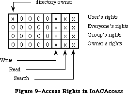 Figure 9–Access Rights in IoACAccess
Bit 7 If set, user is not the owner of the directory.
If clear, user is the owner of the directory.
6–3 Reserved; this is returned set to zero.
2 If set, user does not have Write privileges to the directory.
If clear, user has Write privileges to the directory.
1 If set, user does not have Read privileges to the directory.
If clear, user has Read privileges to the directory.
0 If set, user does not have Search privileges to the directory.
If clear, user has Search privileges to the directory.
The User’s rights information is the logical OR of Everyone’s rights, Group’s rights, and Owner’s rights. It is only returned from the GetDirAccess call; it is never passed by the SetDirAccess call. Likewise, the Owner bit is only returned in the GetDirAccess call. To change a folder’s owner, you must change the Owner ID field of the SetDirAccess call.
For PBHOpenDeny and PBHOpenRFDeny, ioDenyModes contain a word of permissions information, as pictured in Figure 10 (high order bit on the left).
Figure 9–Access Rights in IoACAccess
Bit 7 If set, user is not the owner of the directory.
If clear, user is the owner of the directory.
6–3 Reserved; this is returned set to zero.
2 If set, user does not have Write privileges to the directory.
If clear, user has Write privileges to the directory.
1 If set, user does not have Read privileges to the directory.
If clear, user has Read privileges to the directory.
0 If set, user does not have Search privileges to the directory.
If clear, user has Search privileges to the directory.
The User’s rights information is the logical OR of Everyone’s rights, Group’s rights, and Owner’s rights. It is only returned from the GetDirAccess call; it is never passed by the SetDirAccess call. Likewise, the Owner bit is only returned in the GetDirAccess call. To change a folder’s owner, you must change the Owner ID field of the SetDirAccess call.
For PBHOpenDeny and PBHOpenRFDeny, ioDenyModes contain a word of permissions information, as pictured in Figure 10 (high order bit on the left).
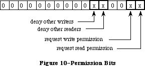 Figure 10–Permission Bits
Bit 15–6 Reserved; this should be set to zero.
5 If set, deny other writers to this file.
4 If set, deny other readers to this file.
3–2 Reserved; this should be set to zero.
1 If set, requesting write permission.
0 If set, requesting read permission.
For PBGetCatInfo, ioACUser (a new byte field) returns the user’s access rights information for a directory whose volume supports access controls in the format shown in Figure 11.
Figure 10–Permission Bits
Bit 15–6 Reserved; this should be set to zero.
5 If set, deny other writers to this file.
4 If set, deny other readers to this file.
3–2 Reserved; this should be set to zero.
1 If set, requesting write permission.
0 If set, requesting read permission.
For PBGetCatInfo, ioACUser (a new byte field) returns the user’s access rights information for a directory whose volume supports access controls in the format shown in Figure 11.
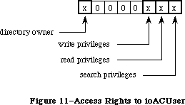 Figure 11–Access Rights in ioACUser
Bit 7 If set, user is not the owner of the directory.
If clear, user is the owner of the directory.
6–3 Reserved; this is returned set to zero.
2 If set, user does not have Write privileges to the directory.
If clear, user has Write privileges to the directory.
1 If set, user does not have Read privileges to the directory.
If clear, user has Read privileges to the directory.
0 If set, user does not have Search privileges to the directory.
If clear, user has Search privileges to the directory.
_______________________________________________________________________________
»INFORMATION USED BY THE FINDER
_______________________________________________________________________________
The file directory (whether hierarchical or flat) lists information about all the files and directories on a volume. This information is returned by the GetFileInfo and GetCatInfo functions.
_______________________________________________________________________________
»Flat Volumes
X-Ref: Technical Note #40
On flat volumes, all of the information used by the Finder is contained in a data structure of type FInfo. (This data structure is also used with hierarchical volumes, along with additional structures described below.) The FInfo data type is defined as follows:
TYPE FInfo = RECORD
fdType: OSType; {file type}
fdCreator: OSType; {file's creator}
fdFlags: INTEGER; {flags}
fdLocation: Point; {file's location}
fdFldr: INTEGER {file's window}
END;
Normally an application need only set the file type and creator when a file is created, and the Finder will manipulate the other fields. (File type and creator are discussed in the Finder Interface chapter.)
FdFlags indicates whether the file’s icon is invisible, whether the file has a bundle, and other characteristics used internally by the Finder:
Bit Meaning
0 Set if file is on desktop (hierarchical volumes only)
13 Set if file has a bundle
14 Set if file’s icon is invisible
Masks for these three bits are available as predefined constants:
CONST fOnDesk = 1; {set if file is on desktop (hierarchical }
{ volumes only)}
fHasBundle = 8192; {set if file has a bundle}
fInvisible = 16384; {set if file's icon is invisible}
For more information about bundles, see the Finder Interface chapter.
FdLocation contains the location of the file’s icon in its window, given in the local coordinate system of the window; it’s used by the Finder to position the icon. FdFldr indicates the window in which the file’s icon will appear, and may contain one of the following values:
CONST fTrash = -3; {file is in Trash window}
fDesktop = -2; {file is on desktop}
fDisk = 0; {file is in disk window}
64K ROM note: The fdFldr field of FInfo is not used with hierarchical volumes.
_______________________________________________________________________________
»Hierarchical Volumes
On hierarchical volumes, in addition to the FInfo record, the following information about files is maintained for the Finder:
TYPE FXInfo = RECORD
fdIconID: INTEGER; {icon ID}
fdUnused: ARRAY[1..4] OF INTEGER; {reserved}
fdComment: INTEGER; {comment ID}
fdPutAway: LONGINT; {home directory ID}
END;
On hierarchical volumes, the following information about directories is maintained for the Finder:
DInfo = RECORD
frRect: Rect; {folder's rectangle}
frFlags: INTEGER; {flags}
frLocation: Point; {folder's location}
frView: INTEGER; {folder's view}
END;
DXInfo = RECORD
frScroll: Point; {scroll position}
frOpenChain: LONGINT; {directory ID chain of open folders}
frUnused: INTEGER; {reserved}
frComment: INTEGER; {comment ID}
frPutAway: LONGINT; {directory ID}
END;
When a file (or folder) is moved to the desktop on a hierarchical volume, it’s actually moved to the root level of the file directory. (This permits all the desktop icons to be enumerated by one simple scan of the root.) The fOnDesk bit of fdFlags is set. FDPutAway (or frPutAway for directories) contains the directory ID of the folder that originally contained the file (or folder); this allows the file (or folder) to be returned there from the desktop.
_______________________________________________________________________________
»HIGH-LEVEL FILE MANAGER ROUTINES
_______________________________________________________________________________
X-Ref: Technical Note #218
This section describes all the high-level Pascal routines of the File Manager. For information on calling the low-level Pascal and assembly-language routines, see the next section.
When accessing a volume other than the default volume, you must identify it by its volume name, its volume reference number, the drive number of its drive, or a working directory reference number. The parameter volName is a pointer, of type StringPtr, to the volume name. DrvNum is an integer that contains the drive number, and vRefNum is an integer that can contain either the volume reference number or a working directory reference number.
Note: VolName is declared as type StringPtr instead of type STRING to allow
you to pass NIL in routines where the parameter is optional.
Warning: Before you pass a parameter of type StringPtr to a File Manager
routine, be sure that memory has been allocated for the variable.
For example, the following statements will ensure that memory is
allocated for the variable myStr:
VAR myStr: Str255;
. . .
result := GetVol(@myStr,myRefNum)
FileName can contain either the file name alone or both the volume name and file name.
Note: The high-level File Manager routines will work only with files
having a version number of 0.
You can’t specify an access path buffer when calling high-level Pascal routines.
All high-level File Manager routines return an integer result code of type OSErr as their function result. Each routine description lists all of the applicable result codes, along with a short description of what the result code means. Lengthier explanations of all the resultcodes can be found in the summary at the end of this chapter.
_______________________________________________________________________________
»Accessing Volumes
X-Ref: Technical Note #24
FUNCTION GetVInfo (drvNum: INTEGER; volName: StringPtr; VAR vRefNum: INTEGER;
VAR freeBytes: LONGINT) : OSErr; [Not in ROM]
X-Ref: Technical Note #157
GetVInfo returns the name, reference number, and available space (in bytes), in volName, vRefNum, and freeBytes, for the volume in the drive specified by drvNum.
Result codes noErr No error
nsvErr No default volume
paramErr Bad drive number
FUNCTION GetVRefNum (pathRefNum: INTEGER; VAR vRefNum: INTEGER) : OSErr;
[Not in ROM]
Given a path reference number in pathRefNum, GetVRefNum returns the volume reference number in vRefNum.
Result codes noErr No error
rfNumErr Bad reference number
FUNCTION GetVol (volName: StringPtr; VAR vRefNum: INTEGER) : OSErr;
[Not in ROM]
GetVol returns the name of the default volume in volName and its volume reference number in vRefNum.
Result codes noErr No error
nsvErr No such volume
FUNCTION SetVol (volName: StringPtr; vRefNum: INTEGER) : OSErr; [Not in ROM]
SetVol sets the default volume to the mounted volume specified by volName or vRefNum.
Result codes noErr No error
bdNamErr Bad volume name
nsvErr No such volume
paramErr No default volume
FUNCTION FlushVol (volName: StringPtr; vRefNum: INTEGER) : OSErr;
[Not in ROM]
On the volume specified by volName or vRefNum, FlushVol writes the contents of the associated volume buffer and descriptive information about the volume (if they’ve changed since the last time FlushVol was called).
Result codes noErr No error
bdNamErr Bad volume name
extFSErr External file system
ioErr I/O error
nsDrvErr No such drive
nsvErr No such volume
paramErr No default volume
FUNCTION UnmountVol (volName: StringPtr; vRefNum: INTEGER) : OSErr;
[Not in ROM]
UnmountVol unmounts the volume specified by volName or vRefNum, by calling FlushVol to flush the volume buffer, closing all open files on the volume, and releasing the memory used for the volume.
Warning: Don’t unmount the startup volume.
Result codes noErr No error
bdNamErr Bad volume name
extFSErr External file system
ioErr I/O error
nsDrvErr No such drive
nsvErr No such volume
paramErr No default volume
FUNCTION Eject (volName: StringPtr; vRefNum: INTEGER) : OSErr; [Not in ROM]
Eject flushes the volume specified by volName or vRefNum, places it off-line, and then ejects the volume.
Result codes noErr No error
bdNamErr Bad volume name
extFSErr External file system
ioErr I/O error
nsDrvErr No such drive
nsvErr No such volume
paramErr No default volume
_______________________________________________________________________________
»Accessing Files
FUNCTION FSOpen (fileName: Str255; vRefNum: INTEGER;
VAR refNum: INTEGER) : OSErr; [Not in ROM]
FSOpen creates an access path to the file having the name fileName on the volume specified by vRefNum. A path reference number is returned in refNum. The access path’s read/write permission is set to whatever the file’s open permission allows.
Note: There’s no guarantee that any bytes have been written until
FlushVol is called.
Result codes noErr No error
bdNamErr Bad file name
extFSErr External file system
fnfErr File not found
ioErr I/O error
nsvErr No such volume
opWrErr File already open for writing
tmfoErr Too many files open
FUNCTION OpenRF (fileName: Str255; vRefNum: INTEGER;
VAR refNum: INTEGER) : OSErr; [Not in ROM]
OpenRF is similar to FSOpen; the only difference is that OpenRF opens the resource fork of the specified file rather than the data fork. A path reference number is returned in refNum. The access path’s read/write permission is set to whatever the file’s open permission allows.
Note: Normally you should access a file’s resource fork through the
routines of the Resource Manager rather than the File Manager.
OpenRF doesn’t read the resource map into memory; it’s really
only useful for block-level operations such as copying files.
Result codes noErr No error
bdNamErr Bad file name
extFSErr External file system
fnfErr File not found
ioErr I/O error
nsvErr No such volume
opWrErr File already open for writing
tmfoErr Too many files open
FUNCTION FSRead (refNum: INTEGER; VAR count: LONGINT;
buffPtr: Ptr) : OSErr; [Not in ROM]
FSRead attempts to read the number of bytes specified by the count parameter from the open file whose access path is specified by refNum, and transfer them to the data buffer pointed to by buffPtr. The read operation begins at the current mark, so you might want to precede this with a call to SetFPos. If you try to read past the logical end-of-file, FSRead moves the mark to the end-of-file and returns eofErr as its function result. After the read is completed, the number of bytes actually read is returned in the count parameter.
Result codes noErr No error
eofErr End-of-file
extFSErr External file system
fnOpnErr File not open
ioErr I/O error
paramErr Negative count
rfNumErr Bad reference number
FUNCTION FSWrite (refNum: INTEGER; VAR count: LONGINT;
buffPtr: Ptr) : OSErr; [Not in ROM]
FSWrite takes the number of bytes specified by the count parameter from the buffer pointed to by buffPtr and attempts to write them to the open file whose access path is specified by refNum. The write operation begins at the current mark, so you might want to precede this with a call to SetFPos. After the write is completed, the number of bytes actually written is returned in the count parameter.
Result codes noErr No error
dskFulErr Disk full
fLckdErr File locked
fnOpnErr File not open
ioErr I/O error
paramErr Negative count
rfNumErr Bad reference number
vLckdErr Software volume lock
wPrErr Hardware volume lock
wrPermErr Read/write permission doesn’t allow writing
FUNCTION GetFPos (refNum: INTEGER; VAR filePos: LONGINT) : OSErr;
[Not in ROM]
GetFPos returns, in filePos, the mark of the open file whose access path is specified by refNum.
Result codes noErr No error
extFSErr External file system
fnOpnErr File not open
ioErr I/O error
rfNumErr Bad reference number
FUNCTION SetFPos (refNum: INTEGER; posMode: INTEGER;
posOff: LONGINT) : OSErr; [Not in ROM]
SetFPos sets the mark of the open file whose access path is specified by refNum to the position specified by posMode and posOff (except when posMode is equal to fsAtMark, in which case posOff is ignored). PosMode indicates how to position the mark; it must contain one of the following values:
CONST fsAtMark = 0; {at current mark}
fsFromStart = 1; {set mark relative to beginning of file}
fsFromLEOF = 2; {set mark relative to logical end-of-file}
fsFromMark = 3; {set mark relative to current mark}
If you specify fsAtMark, posOffset is ignored and the mark is left wherever
it’s currently positioned. If you choose to set the mark (relative to either the beginning of the file, the logical end-of-file, or the current mark), posOffset specifies the byte offset from the chosen point (either positive or negative) where the mark should be set. If you try to set the mark past the logical end-of-file, SetFPos moves the mark to the end-of-file and returns eofErr as its function result.
Result codes noErr No error
eofErr End-of-file
extFSErr External file system
fnOpnErr File not open
ioErr I/O error
posErr Attempt to position before start of file
rfNumErr Bad reference number
FUNCTION GetEOF (refNum: INTEGER; VAR logEOF: LONGINT) : OSErr; [Not in ROM]
GetEOF returns, in logEOF, the logical end-of-file of the open file whose access path is specified by refNum.
Result codes noErr No error
extFSErr External file system
fnOpnErr File not open
ioErr I/O error
rfNumErr Bad reference number
FUNCTION SetEOF (refNum: INTEGER; logEOF: LONGINT) : OSErr; [Not in ROM]
SetEOF sets the logical end-of-file of the open file whose access path is specified by refNum to the position specified by logEOF. If you attempt to set the logical end-of-file beyond the physical end-of-file, the physical end-of-file is set to one byte beyond the end of the next free allocation block; if there isn’t enough space on the volume, no change is made, and SetEOF returns dskFulErr as its function result. If logEOF is 0, all space occupied by the file on the volume is released.
Result codes noErr No error
dskFulErr Disk full
extFSErr External file system
fLckdErr File locked
fnOpnErr File not open
ioErr I/O error
rfNumErr Bad reference number
vLckdErr Software volume lock
wPrErr Hardware volume lock
wrPermErr Read/write permission doesn’t allow writing
FUNCTION Allocate (refNum: INTEGER; VAR count: LONGINT) : OSErr; [Not in ROM]
Allocate adds the number of bytes specified by the count parameter to the open file whose access path is specified by refNum, and sets the physical end-of-file to one byte beyond the last block allocated. The number of bytes actually allocated is rounded up to the nearest multiple of the allocation block size, and returned in the count parameter. If there isn’t enough empty space on the volume to satisfy the allocation request, Allocate allocates the rest of the space on the volume and returns dskFulErr as its function result.
Result codes noErr No error
dskFulErr Disk full
fLckdErr File locked
fnOpnErr File not open
ioErr I/O error
rfNumErr Bad reference number
vLckdErr Software volume lock
wPrErr Hardware volume lock
wrPermErr Read/write permission doesn’t allow writing
FUNCTION FSClose (refNum: INTEGER) : OSErr; [Not in ROM]
FSClose removes the access path specified by refNum, writes the contents of the volume buffer to the volume, and updates the file’s entry in the file directory.
Note: There’s no guarantee that any bytes have been written until
FlushVol is called.
Result codes noErr No error
extFSErr External file system
fnfErr File not found
fnOpnErr File not open
ioErr I/O error
nsvErr No such volume
rfNumErr Bad reference number
_______________________________________________________________________________
»Creating and Deleting Files
FUNCTION Create (fileName: Str255; vRefNum: INTEGER; creator: OSType;
fileType: OSType) : OSErr; [Not in ROM]
Create creates a new file (both forks) with the specified name, file type, and creator on the specified volume. (File type and creator are discussed in the Finder Interface chapter.) The new file is unlocked and empty. The date and time of its creation and last modification are set to the current date and time.
Result codes noErr No error
bdNamErr Bad file name
dupFNErr Duplicate file name and version
dirFulErr File directory full
extFSErr External file system
ioErr I/O error
nsvErr No such volume
vLckdErr Software volume lock
wPrErr Hardware volume lock
FUNCTION FSDelete (fileName: Str255; vRefNum: INTEGER) : OSErr; [Not in ROM]
FSDelete removes the closed file having the name fileName from the specified volume.
Note: This function will delete both forks of a file.
Result codes noErr No error
bdNamErr Bad file name
extFSErr External file system
fBsyErr File busy
fLckdErr File locked
fnfErr File not found
ioErr I/O error
nsvErr No such volume
vLckdErr Software volume lock
wPrErr Hardware volume lock
_______________________________________________________________________________
»Changing Information About Files
All of the routines described in this section affect both forks of the file, and don’t require the file to be open.
FUNCTION GetFInfo (fileName: Str255; vRefNum: INTEGER;
VAR fndrInfo: FInfo) : OSErr; [Not in ROM]
For the file having the name fileName on the specified volume, GetFInfo returns information used by the Finder in fndrInfo (see the section “Information Used by the Finder”).
Result codes noErr No error
bdNamErr Bad file name
extFSErr External file system
fnfErr File not found
ioErr I/O error
nsvErr No such volume
paramErr No default volume
FUNCTION SetFInfo (fileName: Str255; vRefNum: INTEGER;
fndrInfo: FInfo) : OSErr; [Not in ROM]
For the file having the name fileName on the specified volume, SetFInfo sets information used by the Finder to fndrInfo (see the section “Information Used by the Finder”).
Result codes noErr No error
extFSErr External file system
fLckdErr File locked
fnfErr File not found
ioErr I/O error
nsvErr No such volume
vLckdErr Software volume lock
wPrErr Hardware volume lock
FUNCTION SetFLock (fileName: Str255; vRefNum: INTEGER) : OSErr; [Not in ROM]
SetFLock locks the file having the name fileName on the specified volume. Access paths currently in use aren’t affected.
Result codes noErr No error
extFSErr External file system
fnfErr File not found
ioErr I/O error
nsvErr No such volume
vLckdErr Software volume lock
wPrErr Hardware volume lock
FUNCTION RstFLock (fileName: Str255; vRefNum: INTEGER) : OSErr; [Not in ROM]
RstFLock unlocks the file having the name fileName on the specified volume. Access paths currently in use aren’t affected.
Result codes noErr No error
extFSErr External file system
fnfErr File not found
ioErr I/O error
nsvErr No such volume
vLckdErr Software volume lock
wPrErr Hardware volume lock
FUNCTION Rename (oldName: Str255; vRefNum: INTEGER;
newName: Str255) : OSErr; [Not in ROM]
Given a file name in oldName, Rename changes the name of the file to newName. Access paths currently in use aren’t affected. Given a volume name in oldName or a volume reference number in vRefNum, Rename changes the name of the specified volume to newName.
Warning: If you’re renaming a volume, be sure that both names end with a colon.
Result codes noErr No error
bdNamErr Bad file name
dirFulErr Directory full
dupFNErr Duplicate file name
extFSErr External file system
fLckdErr File locked
fnfErr File not found
fsRnErr Problem during rename
ioErr I/O error
nsvErr No such volume
paramErr No default volume
vLckdErr Software volume lock
wPrErr Hardware volume lock
_______________________________________________________________________________
»LOW-LEVEL FILE MANAGER ROUTINES
_______________________________________________________________________________
This section contains information for programmers using the low-level Pascal or assembly-language routines of the File Manager, and describes them in detail.
Most low-level File Manager routines can be executed either synchronously
(meaning that the application can’t continue until the routine is completed) or asynchronously (meaning that the application is free to perform other tasks while the routine is executing). Some, however, can only be executed synchronously because they use the Memory Manager to allocate and release memory.
When an application calls a File Manager routine asynchronously, an I/O request is placed in the file I/O queue, and control returns to the calling program—possibly even before the actual I/O is completed. Requests are taken from the queue one at a time, and processed; meanwhile, the calling program is free to work on other things.
The calling program may specify a completion routine to be executed at the end of an asynchronous operation.
At any time, you can clear all queued File Manager calls except the current one by using the InitQueue procedure. InitQueue is especially useful when an error occurs and you no longer want queued calls to be executed.
_______________________________________________________________________________
»Parameter Blocks
Routine parameters passed by an application to the File Manager and returned by the File Manager to an application are contained in a parameter block, which is a data structure in the heap or stack. When there are a number of parameters to be passed to, or returned from, a routine, the parameters are grouped together in a block and a pointer to the block is passed instead.
Most low-level calls to the File Manager are of the form
FUNCTION PBCallName (paramBlock: PtrToParamBlk; async: BOOLEAN) : OSErr;
PBCallName is the name of the routine. ParamBlock points to the parameter block containing the parameters for the routine; its data type depends on the type of parameter block. If async is TRUE, the call is executed asynchronously; otherwise the call is executed synchronously. The routine returns an integer result code of type OSErr. Each routine description lists all of the applicable result codes, along with a short description of what the result code means. Lengthier explanations of all the result codes can be found in the summary at the end of this chapter.
Assembly-language note: When you call a File Manager routine, A0 must point
to a parameter block containing the parameters for
the routine. If you want the routine to be executed
asynchronously, set bit 10 of the routine trap word.
You can do this by supplying the word ASYNC as the
second argument to the routine macro. For example:
_Read ,ASYNC
You can set or test bit 10 of a trap word by using
the global constant asyncTrpBit. (This syntax applies
to the Lisa Workshop Assembler; programmers using
another development system should consult its
documentation for the proper syntax.)
All File Manager routines except InitQueue return a
result code in D0.
There are many parameters used in the File Manager routines. To group them all together in a single parameter block would be unmanageable, so several different parameter block records have been defined. A summary of these parameter blocks is listed in the “Summary of the File Manager Section.”
ParamBlockRec is the record used by all routines in the 64K ROM version of the File Manager; these routines include general I/O operations, as well as access to information about files and volumes. The RAM-based version of the File Manager provides additional calls that are slight extensions of certain basic routines, allowing you to take advantage of the hierarchical file directory. For instance, HOpen is an extension of the Open call that lets you use a directory ID and a pathname to specify the file to be opened. These hierarchical routines use the record HParamBlockRec, which is a superset of ParamBlockRec.
Assembly-language note: The hierarchical extensions of certain basic File
Manager routines are actually not new calls. For
instance, _Open and _HOpen both trap to the same
routine. The trap word generated by the _HOpen macro
is the same as the trap word that would be generated
by invoking the _Open macro with bit 9 set. (Note that
this is the same bit used in the Device Manager to
indicate that a particular call should be executed
immediately.) The setting of this bit tells the File
Manager to expect a larger parameter block containing
the additional fields (such as a directory ID) needed
to handle a hierarchical directory volume. You can set
or test bit 9 of a trap word by using the global
constant hfsBit.
Three parameter block records—CInfoPBRec, CMovePBRec, and WDPBRec—are used by routines that deal specifically with the hierarchical file directory. These routines work only with the 128K ROM version of the File Manager.
Finally, the record FCBPBRec is used by a single routine, PBGetFCBInfo, to gain access to the contents of a file’s file control block; this routine also works only with the 128K ROM version of the File Manager.
Assembly-language note: You can invoke each of the routines that deal
specifically with the hierarchical file directory
with a macro that has the same name as the routine
preceded by an underscore. These macros, however,
aren’t trap macros themselves; instead they expand
to invoke the trap macro _HFSDispatch. The File
Manager determines which routine to execute from
the routine selector, an integer that’s placed in
register D0. The routine selectors are as follows:
Routine Call number
OpenWD 1
CloseWD 2
CatMove 5
DirCreate 6
GetWDInfo 7
GetFCBInfo 8
GetCatInfo 9
SetCatInfo 10
SetVolInfo 11
LockRng 16
UnlockRng 17
Warning: Using these routines on a Macintosh equipped only with the
64K ROM will result in a system error.
Three of the records—ParamBlockRec, HParamBlockRec, and CInfoPBRec—have CASE statements that separate some of their parameters into functional subsections
(also known as variants of the record). The other records—CMovePBRec, WDPBRec, and FCBPBRec—are not divided in this way.
All of the parameter block records used by the File Manager begin with eight fields of standard information:
qLink: QElemPtr; {next queue entry}
qType: INTEGER; {queue type}
ioTrap: INTEGER; {routine trap}
ioCmdAddr: Ptr; {routine address}
ioCompletion: ProcPtr; {completion routine}
ioResult: OSErr; {result code}
ioNamePtr: StringPtr; {pathname}
ioVRefNum: INTEGER; {volume reference number, drive number, or working }
{ directory reference number}
The first four fields in each parameter block are handled entirely by the File Manager, and most programmers needn’t be concerned with them; programmers who are interested in them should see the section “Data Structures in Memory”.
IOCompletion contains a pointer to a completion routine to be executed at the end of an asynchronous call; it should be NIL for asynchronous calls with no completion routine, and is automatically set to NIL for all synchronous calls.
X-Ref: Technical Note #130
Warning: Completion routines are executed at the interrupt level and must
preserve all registers other than A0, A1, and D0–D2. Your completion
routine must not make any calls to the Memory Manager, directly or
indirectly, and can’t depend on handles to unlocked blocks being
valid. If it uses application globals, it must also ensure that
register A5 contains the address of the boundary between the
application globals and the application parameters; for details,
see SetUpA5 and RestoreA5 in the Operating System Utilities chapter.
When your completion routine is called, register A0 points to the parameter block of the asynchronous call and register D0 contains the result code.
Routines that are executed asynchronously return control to the calling program with the result code noErr as soon as the call is placed in the file I/O queue. This isn’t an indication of successful call completion, but simply indicates that the call was successfully queued.
To determine when the call is actually completed, you can poll the ioResult field; this field is set to 1 when the call is made, and receives the actual result code upon completion of the call. Completion routines are executed after the result code is placed in ioResult.
IONamePtr points to a pathname (i.e. it does not itself contain the characters. It can be either a full or partial pathname. In other words, it can be a volume name (that is, the name of the root directory), a file name, or a concatenation of directory and file names. If ioNamePtr is NIL or points to an improper pathname, an error is returned. For routines that access directories, if a directory ID is specified, ioNamePtr can be NIL.
X-Ref: Technical Note #179
Note: Although ioNamePtr can be a full pathname, you should not require
users to enter full pathnames.
IOVRefNum contains either a volume reference number, a drive number, or a working directory reference number.
The remainder of the parameters are presented below, organized by parameter block records.
»IOParam Variant (ParamBlockRec and HParamBlockRec)
The ioParam variants of ParamBlockRec and HParamBlockRec are identical; the fields are presented below.
ioParam:
(ioRefNum: INTEGER; {path reference number}
ioVersNum: SignedByte; {version number}
ioPermssn: SignedByte; {read/write permission}
ioMisc: Ptr; {miscellaneous}
ioBuffer: Ptr; {data buffer}
ioReqCount: LONGINT; {requested number of bytes}
ioActCount: LONGINT; {actual number of bytes}
ioPosMode: INTEGER; {positioning mode and newline character}
ioPosOffset: LONGINT); {positioning offset}
For routines that access open files, the File Manager determines which file to access by using the path reference number in ioRefNum.
64K ROM note: The 64K ROM version of the File Manager also allows the
specification of a version number to distinguish between
different files with the same name. Version numbers are
generally set to 0, though, because the Resource Manager,
Segment Loader, and Standard File Package won’t operate
on files with nonzero version numbers, and the Finder
ignores version numbers.
IOPermssn requests permission to read or write via an access path, and must contain one of the following values:
CONST fsCurPerm = 0; {whatever is currently allowed}
fsRdPerm = 1; {request for read permission only}
fsWrPerm = 2; {request for write permission}
fsRdWrPerm = 3; {request for exclusive read/write permission}
fsRdWrShPerm = 4; {request for shared read/write permission}
This request is compared with the open permission of the file. If the open permission doesn’t allow I/O as requested, a result code indicating the error is returned.
Warning: To ensure data integrity be sure to lock the portion of the
file you’ll be using if you specify shared write permission.
The content of ioMisc depends on the routine called. It contains either a new logical end-of-file, a new version number, a pointer to an access path buffer, or a pointer to a new pathname. Since ioMisc is of type Ptr, you’ll need to perform type coercion to correctly interpret the value of ioMisc when it contains an end-of-file (a LONGINT) or version number (a SignedByte).
IOBuffer points to a data buffer into which data is written by Read calls and from which data is read by Write calls. IOReqCount specifies the requested number of bytes to be read, written, or allocated. IOActCount contains the number of bytes actually read, written, or allocated.
IOPosMode and ioPosOffset specify the position of the mark for Read, Write, LockRng, UnlockRng, and SetFPos calls. IOPosMode contains the positioning mode; bits 0 and 1 indicate how to position the mark, and you can use the following predefined constants to set or test their value:
CONST fsAtMark = 0; {at current mark}
fsFromStart = 1; {set mark relative to beginning of file}
fsFromLEOF = 2; {set mark relative to logical end-of-file}
fsFromMark = 3; {set mark relative to current mark}
If you specify fsAtMark, ioPosOffset is ignored and the operation begins wherever the mark is currently positioned. If you choose to set the mark
(relative to either the beginning of the file, the logical end-of-file, or the current mark), ioPosOffset must specify the byte offset from the chosen point
(either positive or negative) where the operation should begin.
Note: Advanced programmers: Bit 7 of ioPosMode is the newline flag; it’s
set if read operations should terminate at a newline character. The
ASCII code of the newline character is specified in the high-order
byte of ioPosMode. If the newline flag is set, the data will be read
one byte at a time until the newline character is encountered,
ioReqCount bytes have been read, or the end-of-file is reached. If
the newline flag is clear, the data will be read one byte at a time
until ioReqCount bytes have been read or the end-of-file is reached.
To have the File Manager verify that all data written to a volume exactly matches the data in memory, make a Read call right after the Write call. The parameters for a read-verify operation are the same as for a standard Read call, except that the following constant must be added to the positioning mode:
CONST rdVerify = 64; {read-verify mode}
The result code ioErr is returned if any of the data doesn’t match.
»FileParam Variant (ParamBlockRec and HParamBlockRec)
The fileParam variants of ParamBlockRec and HParamBlockRec are identical, with one exception: The field ioDirID in HParamBlockRec is called ioFlNum in ParamBlockRec. The fields of the fileParam variant of HParamBlockRec are as follows:
X-Ref: Technical Note #204
fileParam:
(ioFRefNum: INTEGER; {path reference number}
ioFVersNum: SignedByte; {version number}
filler1: SignedByte; {not used}
ioFDirIndex: INTEGER; {index}
ioFlAttrib: SignedByte; {file attributes}
ioFlVersNum: SignedByte; {version number}
ioFlFndrInfo: FInfo; {information used by the Finder}
ioDirID: LONGINT; {directory ID or file number}
ioFlStBlk: INTEGER; {first allocation block of data fork}
ioFlLgLen: LONGINT; {logical end-of-file of data fork}
ioFlPyLen: LONGINT; {physical end-of-file of data fork}
ioFlRStBlk: INTEGER; {first allocation block of resource fork}
ioFlRLgLen: LONGINT; {logical end-of-file of resource fork}
ioFlRPyLen: LONGINT; {physical end-of-file of resource fork}
ioFlCrDat: LONGINT; {date and time of creation}
ioFlMdDat: LONGINT); {date and time of last modification}
IOFDirIndex can be used with the PBGetFInfo and PBHGetFInfo to index through the files in a given directory.
Warning: When used with GetFileInfo, ioFDirIndex will index only the files
in a directory. To index both files and directories, you can use
ioFDirIndex with PBGetCatInfo.
IOFlAttrib contains the following file attributes:
Bit Meaning
0 Set if file is locked
2 Set if resource fork is open
3 Set if data fork is open
4 Set if a directory
7 Set if file (either fork) is open
When passed to a routine, ioDirID contains a directory ID; it can be used to refer to a directory or, in conjuction with a partial pathname from that directory, to other files and directories. If both a directory ID and a working directory reference number are provided, the directory ID is used to identify the directory on the volume indicated by the working directory reference number. In other words, a directory ID specified by the caller will override the working directory referred to by the working directory reference number. If you don’t want this to happen, you can set ioDirID to 0. (If no directory is specified through a working directory reference number, the root directory ID will be used.)
When returned from a routine, ioDirID contains the file number of a file; most programmers needn’t be concerned with file numbers, but those interested can read the section “Data Organization on Volumes”.
IOFlStBlk and ioFlRStBlk contain 0 if the file’s data or resource fork is empty, respectively; they’re used only with flat volumes. The date and time in the ioFlCrDat and ioFlMdDat fields are specified in seconds since midnight,
January 1, 1904.
»VolumeParam Variant (ParamBlockRec)
When you call GetVolInfo, you’ll use the volumeParam variant of ParamBlockRec:
volumeParam:
(filler2: LONGINT; {not used}
ioVolIndex: INTEGER; {index}
ioVCrDate: LONGINT; {date and time of initialization}
ioVLsBkUp: LONGINT; {date and time of last modification}
ioVAtrb: INTEGER; {volume attributes}
ioVNmFls: INTEGER; {number of files in root directory}
ioVDirSt: INTEGER; {first block of directory}
ioVBlLn: INTEGER; {length of directory in blocks}
ioVNmAlBlks: INTEGER; {number of allocation blocks}
ioVAlBlkSiz: LONGINT; {size of allocation blocks}
ioVClpSiz: LONGINT; {number of bytes to allocate}
ioAlBlSt: INTEGER; {first block in volume block map}
ioVNxtFNum: LONGINT; {next unused file number}
ioVFrBlk: INTEGER); {number of unused allocation blocks}
IOVolIndex can be used to index through all the mounted volumes; using an index of 1 accesses the first volume mounted, and so on. (For more information on indexing, see the section “Indexing” above.)
IOVLsBkUp contains the date and time the volume information was last modified
(this is not necessarily when it was flushed). (This field is not modified when information is written to a file.)
Note: The name ioVLsBkUp is actually a misnomer; this field has always
contained the date and time of the last modification to the volume,
not the last backup.
Most programmers needn’t be concerned with the remaining parameters, but interested programmers can read the section “Data Organization on Volumes”.
»VolumeParam Variant (HParamBlockRec)
When you call HGetVInfo and SetVolInfo, you’ll use the volumeParam variant of HParamBlockRec. This is a superset of the volumeParam variant of ParamBlockRec; the names and functions of certain fields have been changed, and new fields have been added:
volumeParam:
(filler2: LONGINT; {not used}
ioVolIndex: INTEGER; {index}
ioVCrDate: LONGINT; {date and time of initialization}
ioVLsMod: LONGINT; {date and time of last modification}
ioVAtrb: INTEGER; {volume attributes}
ioVNmFls: INTEGER; {number of files in root directory}
ioVBitMap: INTEGER; {first block of volume bit map}
ioAllocPtr: INTEGER; {block at which next new file starts}
ioVNmAlBlks: INTEGER; {number of allocation blocks}
ioVAlBlkSiz: LONGINT; {size of allocation blocks}
ioVClpSiz: LONGINT; {number of bytes to allocate}
ioAlBlSt: INTEGER; {first block in volume block map}
ioVNxtCNID: LONGINT; {next unused file number}
ioVFrBlk: INTEGER; {number of unused allocation blocks}
ioVSigWord: INTEGER; {volume signature}
ioVDrvInfo: INTEGER; {drive number}
ioVDRefNum: INTEGER; {driver reference number}
ioVFSID: INTEGER; {file system handling this volume}
ioVBkUp: LONGINT; {date and time of last backup}
ioVSeqNum: INTEGER; {used internally}
ioVWrCnt LONGINT; {volume write count}
ioVFilCnt: LONGINT; {number of files on volume}
ioVDirCnt: LONGINT; {number of directories on volume}
ioVFndrInfo: ARRAY[1..8] OF LONGINT); {information used by the Finder}
IOVolIndex can be used to index through all the mounted volumes; using an index of 1 accesses the first volume mounted, and so on. (For more information on indexing, see the section “Indexing” above.)
IOVLsMod contains the date and time the volume information was last modified
(this is not necessarily when it was flushed). (This field is not modified when information is written to a file.)
Note: IOVLsMod replaces the field ioVLsBkUp in ParamBlockRec. The name
ioVLsBkUp was actually a misnomer; this field has always contained
the date and time of the last modification, not the last backup.
Another field, ioVBkUp, contains the date and time of the last backup.
IOVClpSiz can be used to set the volume clump size in bytes; it’s used for files that don’t have a clump size defined as part of their file information in the catalog. To promote file contiguity and avoid fragmentation, space is allocated to a file not in allocation blocks but in clumps. A clump is a group of contiguous allocation blocks. The clump size is always a multiple of the allocation block size; it’s the minimum number of bytes to allocate each time the Allocate function is called or the end-of-file is reached during the Write routine.
IOVSigWord contains a signature word identifying the type of volume; it’s $D2D7 for flat directory volumes and $4244 for hierarchical directory volumes. The drive number of the drive containing the volume is returned in ioDrvInfo. For on-line volumes, ioVDRefNum returns the reference number of the I/O driver for the drive identified by ioDrvInfo.
IOVFSID is the file-system identifier. It indicates which file system is servicing the volume; it’s 0 for File Manager volumes and nonzero for volumes handled by an external file system.
IOVBkUp specifies the date and time the volume was last backed up (it’s 0 if never backed up).
IOVNmFls contains the number of files in the root directory. IOVFilCnt contains the total number of files on the volume, while ioVDirCnt contains the total number of directories (not including the root directory).
Most programmers needn’t be concerned with the other parameters, but interested programmers can read the section “Data Organization on Volumes”.
HParamBlockRec, described above, has been extended to support a shared environment with the addition of AccessParam, ObjParam, CopyParam, and
WDParam, as shown below. (The complete HParamBlockRec data type is shown in the summary.)
AccessParam:
(filler3: INTEGER;
ioDenyModes: INTEGER; {access rights data}
filler4: INTEGER;
filler5: Signed Byte;
ioACUser: Signed Byte; {access rights for directory only}
filler6: LONGINT;
ioACOwnerID: LONGINT; {owner ID}
ioACGroupID: LONGINT; {group ID}
ioACAccess: LONGINT); {access rights}
ObjParam:
(filler7: INTEGER;
ioObjType: INTEGER; {function code}
ioObjNamePtr: Ptr; {ptr to returned creator/group name}
ioObjID: LONGINT; {creator/group ID}
ioReqCount: LONGINT; {size of buffer area}
ioActCount: LONGINT); {length of vol parms data}
CopyParam:
(ioDstVRefNum: INTEGER; {destination vol identifier}
filler8: INTEGER;
ioNewName: Ptr; {ptr to destination pathname}
ioCopyName: Ptr; {ptr to optional name}
ioNewDirID: LONGINT); {destination directory ID}
WDParam:
(filler9: INTEGER;
ioWDIndex: INTEGER;
ioWDProcID: LONGINT;
ioWDVRefNum: INTEGER;
filler10: INTEGER;
filler11: LONGINT;
filler12: LONGINT;
filler13: LONGINT;
ioWDDirID: LONGINT);
»CInfoPBRec
The routines GetCatInfo and SetCatInfo are used for getting and setting information about the files and directories within a directory. With files,
you’ll use the following 19 additional fields after the standard eight fields in the parameter block record CInfoPBRec:
ioFRefNum: INTEGER; {path reference number}
ioFVersNum: SignedByte; {version number}
filler1: SignedByte; {not used}
ioFDirIndex: INTEGER; {index}
ioFlAttrib: SignedByte; {file attributes}
filler2: SignedByte; {not used}
hFileInfo:
(ioFlFndrInfo: FInfo; {information used by the Finder}
ioDirID: LONGINT; {directory ID or file number}
ioFlStBlk: INTEGER; {first allocation block of data fork}
ioFlLgLen: LONGINT; {logical end-of-file of data fork}
ioFlPyLen: LONGINT; {physical end-of-file of data fork}
ioFlRStBlk: INTEGER; {first allocation block of resource fork}
ioFlRLgLen: LONGINT; {logical end-of-file of resource fork}
ioFlRPyLen: LONGINT; {physical end-of-file of resource fork}
ioFlCrDat: LONGINT; {date and time of creation}
ioFlMdDat: LONGINT; {date and time of last modification}
ioFlBkDat: LONGINT; {date and time of last backup}
ioFlXFndrInfo: FXInfo; {additional information used by the Finder}
ioFlParID: LONGINT; {file's parent directory ID (integer)}
ioFlClpSiz: LONGINT); {file's clump size}
X-Ref: Technical Note #69
IOFDirIndex can be used with the function PBGetCatInfo to index through the files and directories in a given directory. For each iteration of the function, you can determine whether it’s a file or a directory by testing bit 4 (the fifth least significant bit) of ioFlAttrib. You can test for a directory by using the Toolbox Utilities BitTst function in the following manner (remember, the Toolbox Utilities routines reverse the standard 68000 notation):
BitTst(@myCInfoRec.ioFlAttrib,3)
IOFlAttrib contains the following attributes:
Bit Meaning
0 Set if file is locked
2 Set if resource fork is open
3 Set if data fork is open
4 Set if a directory
7 Set if file (either fork) is open
When passed to a routine, ioDirID contains a directory ID; it can be used to refer to a directory or, in conjuction with a partial pathname from that directory, to other files and directories. If both a directory ID and a working directory reference number are provided, the directory ID is used to identify the directory on the volume indicated by the working directory reference number. In other words, a directory ID specified by the caller will override the working directory referred to by the working directory reference number. If you don’t want this to happen, you can set ioDirID to 0. (If no directory is specified through a working directory reference number, the root directory ID will be used.)
Warning: With files, ioDirID returns the file number of the file; when
indexing with GetCatInfo, you’ll need to reset this field for
each iteration.
IOFlStBlk and ioFlRStBlk contain 0 if the file’s data or resource fork is empty, respectively; they’re used only with flat volumes. The date and time in the ioFlCrDat, ioFlMdDat, and ioFlBkDat fields are specified in seconds since midnight, January 1, 1904.
IOFlParID contains the directory ID of the file’s parent. IOFlClpSiz is the clump size to be used when writing the file; if it’s 0, the volume’s clump size is used when the file is opened.
With directories, you’ll use the following 14 additional fields after the standard eight fields in the parameter block record CInfoPBRec:
ioFRefNum: INTEGER; {file reference number}
ioFVersNum SignedByte; {version number}
filler1: SignedByte; {not used}
ioFDirIndex: INTEGER; {index}
ioFlAttrib: SignedByte; {file attributes}
filler2: SignedByte; {not used}
dirInfo:
(ioDrUsrWds: DInfo; {information used by the Finder}
ioDrDirID: LONGINT; {directory ID}
ioDrNmFls: INTEGER; {number of files in directory}
filler3: ARRAY[1..9] OF INTEGER; {not used}
ioDrCrDat: LONGINT; {date and time of creation}
ioDrMdDat: LONGINT; {date and time of last modification}
ioDrBkDat: LONGINT; {date and time of last backup}
ioDrFndrInfo: DXInfo; {additional information used by the Finder}
ioDrParID: LONGINT); {directory's parent directory ID (integer)}
IOFDirIndex can be used with the function PBGetCatInfo to index through the files and directories in a given directory. For each iteration of the function, you can determine whether it’s a file or a directory by testing bit 4 of ioFlAttrib.
When passed to a routine, ioDrDirID contains a directory ID; it can be used to refer to a directory or, in conjuction with a partial pathname from that directory, to other files and directories. If both a directory ID and a working directory reference number are provided, the directory ID is used to identify the directory on the volume indicated by the working directory reference number. In other words, a directory ID specified by the caller will override the working directory referred to by the working directory reference number. If you don’t want this to happen, you can set ioDirID to 0. (If no directory is specified through a working directory reference number, the root directory ID will be used.)
With directories, ioDrDirID returns the directory ID of the directory.
IODrNmFls is the number of files and directories contained in this directory
(the valence of the directory).
The date and time in the ioDrCrDat, ioDrMdDat, and ioDrBkDat fields are specified in seconds since midnight, January 1, 1904.
IODrParID contains the directory ID of the directory’s parent.
»CMovePBRec
When you call CatMove to move files or directories into a different directory, you’ll use the following six additional fields after the standard eight fields in the parameter block record CMovePBRec:
filler1: LONGINT; {not used}
ioNewName: StringPtr; {name of new directory}
filler2: LONGINT; {not used}
ioNewDirID: LONGINT; {directory ID of new directory}
filler3: ARRAY[1..2] OF LONGINT; {not used}
ioDirID: LONGINT); {directory ID of current directory}
IONewName and ioNewDirID specify the name and directory ID of the directory to which the file or directory is to be moved. IODirID (used in conjuntion with the ioVRefNum and ioNamePtr) specifies the current directory ID of the file or directory to be moved.
»WDPBRec
When you call the routines that open, close, and get information about working directories, you’ll use the following six additional fields after the standard eight fields in the parameter block record WDPBRec:
filler1: INTEGER; {not used}
ioWDIndex: INTEGER; {index}
ioWDProcID: LONGINT; {working directory user identifier}
ioWDVRefNum: INTEGER; {working directory's volume reference number}
filler2: ARRAY[1..7] OF INTEGER; {not used}
ioWDDirID: LONGINT); {working directory's directory ID}
IOWDIndex can be used with the function PBGetWDInfo to index through the current working directories.
IOWDProcID is an identifier that’s used to distinguish between working directories set up by different users; you should use the application’s signature (discussed in the Finder Interface chapter) as the ioWDProcID.
_______________________________________________________________________________
»Routine Descriptions
Each routine description includes the low-level Pascal form of the call and the routine’s assembly-language macro. A list of the parameter block fields used by the call is also given.
Assembly-language note: The field names given in these descriptions are
those found in the Pascal parameter block records;
see the summary at the end of this chapter for the
names of the corresponding assembly-language offsets.
(The names for some offsets differ from their Pascal
equivalents, and in certain cases more than one name
for the same offset is provided.)
The number next to each parameter name indicates the byte offset of the parameter from the start of the parameter block pointed to by register A0; only assembly-language programmers need be concerned with it. An arrow next to each parameter name indicates whether it’s an input, output, or input/output parameter:
Arrow Meaning
--> Parameter is passed to the routine
<-- Parameter is returned by the routine
<-> Parameter is passed to and returned by the routine
Warning: You must pass something (even if it’s NIL) for each of the
parameters shown for a particular routine; if you don’t, the
File Manager may use garbage that’s sitting at a particular offset.
»Initializing the File I/O Queue
PROCEDURE FInitQueue;
Trap macro _InitQueue
FInitQueue clears all queued File Manager calls except the current one.
»Accessing Volumes
To get the volume reference number of a volume, given the path reference number of a file on that volume, both Pascal and assembly-language programmers can call the high-level File Manager function GetVRefNum. Assembly-language programmers may prefer calling the function GetFCBInfo (described below in the section “Data Structures in Memory”).
FUNCTION PBMountVol (paramBlock: ParmBlkPtr) : OSErr;
Trap macro _MountVol
Parameter block
<-- 16 ioResult word
<-> 22 ioVRefNum word
PBMountVol mounts the volume in the drive specified by ioVRefNum, and returns a volume reference number in ioVRefNum. If there are no volumes already mounted, this volume becomes the default volume. PBMountVol is always executed synchronously.
Note: When mounting hierarchical volumes, PBMountVol opens two files
needed for maintaining file directory and file mapping information.
PBMountVol can fail if there are no access paths available for these
two files; it will return tmfoErr as its function result.
Result codes noErr No error
badMDBErr Bad master directory block
extFSErr External file system
ioErr I/O error
memFullErr Not enough room in heap zone
noMacDskErr Not a Macintosh disk
nsDrvErr No such drive
paramErr Bad drive number
tmfoErr Too many files open
volOnLinErr Volume already on-line
FUNCTION PBGetVInfo (paramBlock: ParmBlkPtr; async: BOOLEAN) : OSErr;
Trap macro _GetVolInfo
Parameter block
--> 12 ioCompletion pointer
<-- 16 ioResult word
<-> 18 ioNamePtr pointer
<-> 22 ioVRefNum word
--> 28 ioVolIndex word
<-- 30 ioVCrDate long word
<-- 34 ioVLsBkUp long word
<-- 38 ioVAtrb word
<-- 40 ioVNmFls word
<-- 42 ioVDirSt word
<-- 44 ioVBlLn word
<-- 46 ioVNmAlBlks word
<-- 48 ioVAlBlkSiz long word
<-- 52 ioVClpSiz long word
<-- 56 ioAlBlSt word
<-- 58 ioVNxtFNum long word
<-- 62 ioVFrBlk word
PBGetVInfo returns information about the specified volume. If ioVolIndex is positive, the File Manager attempts to use it to find the volume; for instance, if ioVolIndex is 2, the File Manager will attempt to access the second mounted volume. If ioVolIndex is negative, the File Manager uses ioNamePtr and ioVRefNum in the standard way (described in the section “Specifying Volumes, Directories, and Files”) to determine which volume. If ioVolIndex is 0, the File Manager attempts to access the volume by using ioVRefNum only. The volume reference number is returned in ioVRefNum, and a pointer to the volume name is returned in ioNamePtr (unless ioNamePtr is NIL).
If a working directory reference number is passed in ioVRefNum (or if the default directory is a subdirectory), the number of files and directories in the specified directory (the directory’s valence) will be returned in ioVNmFls. Also, the volume reference number won’t be returned; ioVRefNum will still contain the working directory reference number.
Warning: IOVNmAlBlks and ioVFrBlks, which are actually unsigned integers,
are clipped to 31744 ($7C00) regardless of the size of the volume.
Result codes noErr No error
nsvErr No such volume
paramErr No default volume
FUNCTION PBHGetVInfo (paramBlock: HParmBlkPtr; async: BOOLEAN) : OSErr;
Trap macro _HGetVInfo
Parameter block
--> 12 ioCompletion pointer
<-- 16 ioResult word
<-> 18 ioNamePtr pointer
<-> 22 ioVRefNum word
--> 28 ioVolIndex word
<-- 30 ioVCrDate long word
<-- 34 ioVLsMod long word
<-- 38 ioVAtrb word
<-- 40 ioVNmFls word
<-- 42 ioVBitMap word
<-- 44 ioVAllocPtr word
<-- 46 ioVNmAlBlks word
<-- 48 ioVAlBlkSiz long word
<-- 52 ioVClpSiz long word
<-- 56 ioAlBlSt word
<-- 58 ioVNxtFNum long word
<-- 62 ioVFrBlk word
<-- 64 ioVSigWord word
<-- 66 ioVDrvInfo word
<-- 68 ioVDRefNum word
<-- 70 ioVFSID word
<-- 72 ioVBkUp long word
<-- 76 ioVSeqNum word
<-- 78 ioVWrCnt long word
<-- 82 ioVFilCnt long word
<-- 86 ioVDirCnt long word
<-- 90 ioVFndrInfo 32 bytes
PBHGetVInfo is similar in function to PBGetVInfo but returns a larger parameter block. In addition, PBHGetVInfo always returns the volume reference number in ioVRefNum (regardless of what was passed in). Also, ioVNmAlBlks and ioVFrBlks are not clipped as they are by PBGetVInfo.
Result codes noErr No error
nsvErr No such volume
paramErr No default volume
FUNCTION PBSetVInfo (paramBlock: HParmBlkPtr; async: BOOLEAN) : OSErr;
X-Ref: Technical Note #204
Trap macro _SetVolInfo
Parameter block
--> 12 ioCompletion pointer
<-- 16 ioResult word
--> 18 ioNamePtr pointer
--> 22 ioVRefNum word
--> 30 ioVCrDate long word
--> 34 ioVLsMod long word
--> 38 ioVAtrb word
--> 52 ioVClpSiz long word
--> 72 ioVBkUp long word
--> 76 ioVSeqNum word
--> 90 ioVFndrInfo 32 bytes
PBSetVInfo lets you modify information about volumes. A pointer to a new name for the volume can be specified in ioNamePtr. The date and time of the volume’s creation and modification can be set with ioVCrDate and ioVLsMod respectively. Only bit 15 of ioVAtrb can be changed; setting it locks the volume.
Note: The volume cannot be specified by name; you must use either the
volume reference number or the drive number.
Warning: PBSetVInfo operates only with the hierarchical version of the
File Manager; if used on a Macintosh equipped only with the
64K ROM version of the File Manager, it will generate a system error.
Result codes noErr No error
nsvErr No such volume
paramErr No default volume
FUNCTION PBGetVol (paramBlock: ParmBlkPtr; async: BOOLEAN) : OSErr;
Trap macro _GetVol
Parameter block
--> 12 ioCompletion pointer
<-- 16 ioResult word
<-- 18 ioNamePtr pointer
<-- 22 ioVRefNum word
PBGetVol returns a pointer to the name of the default volume in ioNamePtr
(unless ioNamePtr is NIL) and its volume reference number in ioVRefNum. If a default directory was set with a previous PBSetVol call, a pointer to its name will be returned in ioNamePtr and its working directory reference number in ioVRefNum.
Result codes noErr No error
nsvErr No default volume
FUNCTION PBHGetVol (paramBlock: WDPBPtr; async: BOOLEAN) : OSErr;
Trap macro _HGetVol
Parameter block
--> 12 ioCompletion pointer
<-- 16 ioResult word
<-- 18 ioNamePtr pointer
<-- 22 ioVRefNum word
<-- 28 ioWDProcID long word
<-- 32 ioWDVRefNum word
<-- 48 ioWDDirID long word
PBHGetVol returns the default volume and directory last set by either a PBSetVol or a PBHSetVol call. The reference number of the default volume is returned in ioVRefNum.
Warning: IOVRefNum will return a working directory reference number
(instead of the volume reference number) if, in the last call
to PBSetVol or PBHSetVol, a working directory reference number
was passed in this field.
The volume reference number of the volume on which the default directory exists is returned in ioWDVRefNum. The directory ID of the default directory is returned in ioWDDirID.
Result codes noErr No error
nsvErr No default volume
FUNCTION PBSetVol (paramBlock: ParmBlkPtr; async: BOOLEAN) : OSErr;
Trap macro _SetVol
Parameter block
--> 12 ioCompletion pointer
<-- 16 ioResult word
--> 18 ioNamePtr pointer
--> 22 ioVRefNum word
PBSetVol sets the default volume to the mounted volume specified by ioNamePtr or ioVRefNum. On hierarchical volumes, PBSetVol also sets the root directory as the default directory.
Result codes noErr No error
bdNamErr Bad volume name
nsvErr No such volume
paramErr No default volume
FUNCTION PBHSetVol (paramBlock: WDPBPtr; async: BOOLEAN) : OSErr;
X-Ref: Technical Note #140
Trap macro _HSetVol
Parameter block
--> 12 ioCompletion pointer
<-- 16 ioResult word
--> 18 ioNamePtr pointer
--> 22 ioVRefNum word
--> 48 ioWDDirID long word
PBHSetVol sets both the default volume and the default directory. The default directory to be used can be specified by either a volume reference number or a working directory reference number in ioVRefNum, a directory ID in ioWDDirID, or a pointer to a pathname (possibly NIL) in ioNamePtr.
Note: Both the default volume and the default directory are used in
calls made with no volume name and a volume reference number of zero.
Result codes noErr No error
nsvErr No default volume
FUNCTION PBFlushVol (paramBlock: ParmBlkPtr; async: BOOLEAN) : OSErr;
Trap macro _FlushVol
Parameter block
--> 12 ioCompletion pointer
<-- 16 ioResult word
--> 18 ioNamePtr pointer
--> 22 ioVRefNum word
On the volume specified by ioNamePtr or ioVRefNum, PBFlushVol writes descriptive information about the volume, the contents of the associated volume buffer, and all access path buffers for the volume (if they’ve changed since the last time PBFlushVol was called).
Note: The date and time of the last modification to the volume are set
when the modification is made, not when the volume is flushed.
Result codes noErr No error
bdNamErr Bad volume name
extFSErr External file system
ioErr I/O error
nsDrvErr No such drive
nsvErr No such volume
paramErr No default volume
FUNCTION PBUnmountVol (paramBlock: ParmBlkPtr) : OSErr;
Trap macro _UnmountVol
Parameter block
<-- 16 ioResult word
--> 18 ioNamePtr pointer
--> 22 ioVRefNum word
PBUnmountVol unmounts the volume specified by ioNamePtr or ioVRefNum, by calling PBFlushVol to flush the volume, closing all open files on the volume, and releasing the memory used for the volume. PBUnmountVol is always executed synchronously.
Warning: Don’t unmount the startup volume.
Note: Unmounting a volume does not close working directories; to release
the memory allocated to a working directory, call PBCloseWD.
Result codes noErr No error
bdNamErr Bad volume name
extFSErr External file system
ioErr I/O error
nsDrvErr No such drive
nsvErr No such volume
paramErr No default volume
FUNCTION PBOffLine (paramBlock: ParmBlkPtr) : OSErr;
Trap macro _OffLine
Parameter block
--> 12 ioCompletion pointer
<-- 16 ioResult word
--> 18 ioNamePtr pointer
--> 22 ioVRefNum word
PBOffLine places off-line the volume specified by ioNamePtr or ioVRefNum, by calling PBFlushVol to flush the volume and releasing all the memory used for the volume except for the volume control block. PBOffLine is always executed synchronously.
Result codes noErr No error
bdNamErr Bad volume name
extFSErr External file system
ioErr I/O error
nsDrvErr No such drive
nsvErr No such volume
paramErr No default volume
FUNCTION PBEject (paramBlock: ParmBlkPtr) : OSErr;
Trap macro _Eject
Parameter block
--> 12 ioCompletion pointer
<-- 16 ioResult word
--> 18 ioNamePtr pointer
--> 22 ioVRefNum word
PBEject flushes the volume specified by ioNamePtr or ioVRefNum, places it
off-line, and then ejects the volume.
Assembly-language note: You may invoke the macro _Eject asynchronously;
the first part of the call is executed synchronously,
and the actual ejection is executed asynchronously.
Result codes noErr No error
bdNamErr Bad volume name
extFSErr External file system
ioErr I/O error
nsDrvErr No such drive
nsvErr No such volume
paramErr No default volume
»Accessing Files
FUNCTION PBOpen (paramBlock: ParmBlkPtr; async: BOOLEAN) : OSErr;
Trap macro _Open
Parameter block
--> 12 ioCompletion pointer
<-- 16 ioResult word
--> 18 ioNamePtr pointer
--> 22 ioVRefNum word
<-- 24 ioRefNum word
--> 26 ioVersNum byte
--> 27 ioPermssn byte
--> 28 ioMisc pointer
PBOpen creates an access path to the file having the name pointed to by ioNamePtr (and on flat volumes, the version number ioVersNum) on the volume specified by ioVRefNum. A path reference number is returned in ioRefNum.
IOMisc either points to a portion of memory (522 bytes) to be used as the access path’s buffer, or is NIL if you want the volume buffer to be used instead.
Warning: All access paths to a single file that’s opened multiple times
should share the same buffer so that they will read and write
the same data.
IOPermssn specifies the path’s read/write permission. A path can be opened for writing even if it accesses a file on a locked volume, and an error won’t be returned until a PBWrite, PBSetEOF, or PBAllocate call is made.
If you attempt to open a locked file for writing, PBOpen will return permErr as its function result. If you request exclusive read/write permission but another access path already has write permission (whether write only, exclusive
read/write, or shared read/write), PBOpen will return the reference number of the existing access path in ioRefNum and opWrErr as its function result. Similarly, if you request shared read/write permission but another access path already has exclusive read/write permission, PBOpen will return the reference number of the access path in ioRefNum and opWrErr as its function result.
Result codes noErr No error
bdNamErr Bad file name
extFSErr External file system
fnfErr File not found
ioErr I/O error
nsvErr No such volume
opWrErr File already open for writing
permErr Attempt to open locked file for writing
tmfoErr Too many files open
FUNCTION PBHOpen (paramBlock: HParmBlkPtr; async: BOOLEAN) : OSErr;
Trap macro _HOpen
Parameter block
--> 12 ioCompletion pointer
<-- 16 ioResult word
--> 18 ioNamePtr pointer
--> 22 ioVRefNum word
<-- 24 ioRefNum word
--> 27 ioPermssn byte
--> 28 ioMisc pointer
--> 48 ioDirID long word
PBHOpen is identical to PBOpen except that it accepts a directory ID in ioDirID.
Result codes noErr No error
bdNamErr Bad file name
dirNFErr Directory not found or incomplete pathname
extFSErr External file system
fnfErr File not found
ioErr I/O error
nsvErr No such volume
opWrErr File already open for writing
permErr Attempt to open locked file for writing
tmfoErr Too many files open
FUNCTION PBOpenRF (paramBlock: ParmBlkPtr; async: BOOLEAN) : OSErr;
Trap macro _OpenRF
Parameter block
--> 12 ioCompletion pointer
<-- 16 ioResult word
--> 18 ioNamePtr pointer
--> 22 ioVRefNum word
<-- 24 ioRefNum word
--> 26 ioVersNum byte
--> 27 ioPermssn byte
--> 28 ioMisc pointer
PBOpenRF is identical to PBOpen, except that it opens the file’s resource fork instead of its data fork.
Note: Normally you should access a file’s resource fork through the
routines of the Resource Manager rather than the File Manager.
PBOpenRF doesn’t read the resource map into memory; it’s really
only useful for block-level operations such as copying files.
Result codes noErr No error
bdNamErr Bad file name
extFSErr External file system
fnfErr File not found
ioErr I/O error
nsvErr No such volume
opWrErr File already open for writing
permErr Attempt to open locked file for writing
tmfoErr Too many files open
FUNCTION PBHOpenRF (paramBlock: HParmBlkPtr; async: BOOLEAN) : OSErr;
Trap macro _HOpenRF
Parameter block
--> 12 ioCompletion pointer
<-- 16 ioResult word
--> 18 ioNamePtr pointer
--> 22 ioVRefNum word
<-- 24 ioRefNum word
--> 27 ioPermssn byte
--> 28 ioMisc pointer
--> 48 ioDirID long word
PBHOpenRF is identical to PBOpenRF except that it accepts a directory ID in ioDirID.
Result codes noErr No error
bdNamErr Bad file name
dirNFErr Directory not found or incomplete pathname
extFSErr External file system
fnfErr File not found
ioErr I/O error
nsvErr No such volume
opWrErr File already open for writing
permErr Attempt to open locked file for writing
tmfoErr Too many files open
FUNCTION PBLockRange (paramBlock: ParmBlkPtr; async: BOOLEAN) : OSErr;
X-Ref: Technical Note #186
Trap macro _LockRng
Parameter block
--> 12 ioCompletion pointer
<-- 16 ioResult word
--> 24 ioRefNum word
--> 36 ioReqCount long word
--> 44 ioPosMode word
--> 46 ioPosOffset long word
On a file opened with a shared read/write permission, PBLockRange is used in conjunction with PBRead and PBWrite to lock a certain portion of the file. PBLockRange uses the same parameters as both PBRead and PBWrite; by calling it immediately before PBRead, you can use the information present in the parameter block for the PBRead call.
When you’re finished with the data (typically after a call to PBWrite), be sure to call PBUnlockRange to free up that portion of the file for subsequent PBRead calls.
Warning: PBLockRange operates only with the hierarchical version of the
File Manager; if used on a Macintosh equipped only with the 64K
ROM version of the File Manager, it will generate a system error.
Result codes noErr No error
eofErr End-of-file
extFSErr External file system
fnOpnErr File not open
ioErr I/O error
paramErr Negative ioReqCount
rfNumErr Bad reference number
FUNCTION PBUnlockRange (paramBlock: ParmBlkPtr; async: BOOLEAN) : OSErr;
Trap macro _UnlockRng
Parameter block
--> 12 ioCompletion pointer
<-- 16 ioResult word
--> 24 ioRefNum word
--> 36 ioReqCount long word
--> 44 ioPosMode word
--> 46 ioPosOffset long word
PBUnlockRange is used in conjunction with PBRead and PBWrite to unlock a certain portion of a file that you locked with PBLockRange.
Warning: PBUnlockRange operates only with the hierarchical version of
the File Manager; if used on a Macintosh equipped only with
the 64K ROM version of the File Manager, it will generate a
system error.
Result codes noErr No error
eofErr End-of-file
extFSErr External file system
fnOpnErr File not open
ioErr I/O error
paramErr Negative ioReqCount
rfNumErr Bad reference number
FUNCTION PBRead (paramBlock: ParmBlkPtr; async: BOOLEAN) : OSErr;
Trap macro _Read
Parameter block
--> 12 ioCompletion pointer
<-- 16 ioResult word
--> 24 ioRefNum word
--> 32 ioBuffer pointer
--> 36 ioReqCount long word
<-- 40 ioActCount long word
--> 44 ioPosMode word
<-> 46 ioPosOffset long word
PBRead attempts to read ioReqCount bytes from the open file whose access path is specified by ioRefNum, and transfer them to the data buffer pointed to by ioBuffer. The position of the mark is specified by ioPosMode and ioPosOffset. If you try to read past the logical end-of-file, PBRead moves the mark to the end-of-file and returns eofErr as its function result. After the read is completed, the mark is returned in ioPosOffset and the number of bytes actually read is returned in ioActCount.
Result codes noErr No error
eofErr End-of-file
extFSErr External file system
fnOpnErr File not open
ioErr I/O error
paramErr Negative ioReqCount
rfNumErr Bad reference number
FUNCTION PBWrite (paramBlock: ParmBlkPtr; async: BOOLEAN) : OSErr;
Trap macro _Write
Parameter block
--> 12 ioCompletion pointer
<-- 16 ioResult word
--> 24 ioRefNum word
--> 32 ioBuffer pointer
--> 36 ioReqCount long word
<-- 40 ioActCount long word
--> 44 ioPosMode word
<-> 46 ioPosOffset long word
PBWrite takes ioReqCount bytes from the buffer pointed to by ioBuffer and attempts to write them to the open file whose access path is specified by ioRefNum. The position of the mark is specified by ioPosMode and ioPosOffset. After the write is completed, the mark is returned in ioPosOffset and the number of bytes actually written is returned in ioActCount.
Result codes noErr No error
dskFulErr Disk full
fLckdErr File locked
fnOpnErr File not open
ioErr I/O error
paramErr Negative ioReqCount
posErr Attempt to position before start of file
rfNumErr Bad reference number
vLckdErr Software volume lock
wPrErr Hardware volume lock
wrPermErr Read/write permission doesn’t allow writing
FUNCTION PBGetFPos (paramBlock: ParmBlkPtr; async: BOOLEAN) : OSErr;
Trap macro _GetFPos
Parameter block
--> 12 ioCompletion pointer
<-- 16 ioResult word
--> 24 ioRefNum word
<-- 36 ioReqCount long word
<-- 40 ioActCount long word
<-- 44 ioPosMode word
<-- 46 ioPosOffset long word
PBGetFPos returns, in ioPosOffset, the mark of the open file whose access path is specified by ioRefNum. It sets ioReqCount, ioActCount, and ioPosMode to 0.
Result codes noErr No error
extFSErr External file system
fnOpnErr File not open
gfpErr Error during GetFPos
ioErr I/O error
rfNumErr Bad reference number
FUNCTION PBSetFPos (paramBlock: ParmBlkPtr; async: BOOLEAN) : OSErr;
Trap macro _SetFPos
Parameter block
--> 12 ioCompletion pointer
<-- 16 ioResult word
--> 24 ioRefNum word
--> 44 ioPosMode word
<-> 46 ioPosOffset long word
PBSetFPos sets the mark of the open file whose access path is specified by ioRefNum to the position specified by ioPosMode and ioPosOffset. The position at which the mark is actually set is returned in ioPosOffset. If you try to set the mark past the logical end-of-file, PBSetFPos moves the mark to the end-of-file and returns eofErr as its function result.
Result codes noErr No error
eofErr End-of-file
extFSErr External file system
fnOpnErr File not open
ioErr I/O error
posErr Attempt to position before start of file
rfNumErr Bad reference number
FUNCTION PBGetEOF (paramBlock: ParmBlkPtr; async: BOOLEAN) : OSErr;
Trap macro _GetEOF
Parameter block
--> 12 ioCompletion pointer
<-- 16 ioResult word
--> 24 ioRefNum word
<-- 28 ioMisc long word
PBGetEOF returns, in ioMisc, the logical end-of-file of the open file whose access path is specified by ioRefNum.
Result codes noErr No error
extFSErr External file system
fnOpnErr File not open
ioErr I/O error
rfNumErr Bad reference number
FUNCTION PBSetEOF (paramBlock: ParmBlkPtr; async: BOOLEAN) : OSErr;
Trap macro _SetEOF
Parameter block
--> 12 ioCompletion pointer
<-- 16 ioResult word
--> 24 ioRefNum word
--> 28 ioMisc long word
PBSetEOF sets the logical end-of-file of the open file, whose access path is specified by ioRefNum, to ioMisc. If you attempt to set the logical end-of-file beyond the physical end-of-file, another allocation block is added to the file; if there isn’t enough space on the volume, no change is made, and PBSetEOF returns dskFulErr as its function result. If ioMisc is 0, all space occupied by the file on the volume is released.
Result codes noErr No error
dskFulErr Disk full
extFSErr External file system
fLckdErr File locked
fnOpnErr File not open
ioErr I/O error
rfNumErr Bad reference number
vLckdErr Software volume lock
wPrErr Hardware volume lock
wrPermErr Read/write permission doesn’t allow writing
FUNCTION PBAllocate (paramBlock: ParmBlkPtr; async: BOOLEAN) : OSErr;
Trap macro _Allocate
Parameter block
--> 12 ioCompletion pointer
<-- 16 ioResult word
--> 24 ioRefNum word
--> 36 ioReqCount long word
<-- 40 ioActCount long word
PBAllocate adds ioReqCount bytes to the open file whose access path is specified by ioRefNum, and sets the physical end-of-file to one byte beyond the last block allocated. The number of bytes actually allocated is rounded up to the nearest multiple of the allocation block size, and returned in ioActCount. If there isn’t enough empty space on the volume to satisfy the allocation request, PBAllocate allocates the rest of the space on the volume and returns dskFulErr as its function result.
Note: Even if the total number of requested bytes is unavailable,
PBAllocate will allocate whatever space, contiguous or not, is
available. To force the allocation of the entire requested space
as a contiguous piece, call PBAllocContig instead.
Result codes noErr No error
dskFulErr Disk full
fLckdErr File locked
fnOpnErr File not open
ioErr I/O error
rfNumErr Bad reference number
vLckdErr Software volume lock
wPrErr Hardware volume lock
wrPermErr Read/write permission doesn’t allow writing
FUNCTION PBAllocContig (paramBlock: ParmBlkPtr; async: BOOLEAN) : OSErr;
Trap macro _AllocContig
Parameter block
--> 12 ioCompletion pointer
<-- 16 ioResult word
--> 24 ioRefNum word
--> 36 ioReqCount long word
<-- 40 ioActCount long word
PBAllocContig is identical to PBAllocate except that if there isn’t enough contiguous empty space on the volume to satisfy the allocation request, PBAllocContig will do nothing and will return dskFulErr as its function result. If you want to allocate whatever space is available, even when the entire request cannot be filled as a contiguous piece, call PBAllocate instead.
Result codes noErr No error
dskFulErr Disk full
fLckdErr File locked
fnOpnErr File not open
ioErr I/O error
rfNumErr Bad reference number
vLckdErr Software volume lock
wPrErr Hardware volume lock
wrPermErr Read/write permission doesn’t allow writing
FUNCTION PBFlushFile (paramBlock: ParmBlkPtr; async: BOOLEAN) : OSErr;
Trap macro _FlushFile
Parameter block
--> 12 ioCompletion pointer
<-- 16 ioResult word
--> 24 ioRefNum word
PBFlushFile writes the contents of the access path buffer indicated by ioRefNum to the volume, and updates the file’s entry in the file directory (or in the file catalog, in the case of hierarchical volumes).
Warning: Some information stored on the volume won’t be correct
until PBFlushVol is called.
Result codes noErr No error
extFSErr External file system
fnfErr File not found
fnOpnErr File not open
ioErr I/O error
nsvErr No such volume
rfNumErr Bad reference number
FUNCTION PBClose (paramBlock: ParmBlkPtr; async: BOOLEAN) : OSErr;
Trap macro _Close
Parameter block
--> 12 ioCompletion pointer
<-- 16 ioResult word
--> 24 ioRefNum word
PBClose writes the contents of the access path buffer specified by ioRefNum to the volume and removes the access path.
Warning: Some information stored on the volume won’t be correct
until PBFlushVol is called.
Result codes noErr No error
extFSErr External file system
fnfErr File not found
fnOpnErr File not open
ioErr I/O error
nsvErr No such volume
rfNumErr Bad reference number
»Creating and Deleting Files and Directories
FUNCTION PBCreate (paramBlock: ParmBlkPtr; async: BOOLEAN) : OSErr;
Trap macro _Create
Parameter block
--> 12 ioCompletion pointer
<-- 16 ioResult word
--> 18 ioNamePtr pointer
--> 22 ioVRefNum word
--> 26 ioFVersNum byte
PBCreate creates a new file (both forks) having the name pointed to by ioNamePtr (and on flat volumes, the version number ioVersNum) on the volume specified by ioVRefNum. The new file is unlocked and empty. The date and time of its creation and last modification are set to the current date and time. If the file created isn’t temporary (that is, if it will exist after the application terminates), the application should call PBSetFInfo (after PBCreate) to fill in the information needed by the Finder.
Assembly-language note: If a desk accessory creates a file, it should
always create it in the directory containing the
system folder. The working directory reference
number for this directory is stored in the global
variable BootDrive; you can pass it in ioVRefNum.
Result codes noErr No error
bdNamErr Bad file name
dupFNErr Duplicate file name and version
dirFulErr File directory full
extFSErr External file system
ioErr I/O error
nsvErr No such volume
vLckdErr Software volume lock
wPrErr Hardware volume lock
FUNCTION PBHCreate (paramBlock: HParmBlkPtr; async: BOOLEAN) : OSErr;
Trap macro _HCreate
Parameter block
--> 12 ioCompletion pointer
<-- 16 ioResult word
--> 18 ioNamePtr pointer
--> 22 ioVRefNum word
--> 48 ioDirID long word
PBHCreate is identical to PBCreate except that it accepts a directory ID in ioDirID.
Note: To create a directory instead of a file, call PBDirCreate.
Result codes noErr No error
bdNamErr Bad file name
dupFNErr Duplicate file name and version
dirFulErr File directory full
dirNFErr Directory not found or incomplete pathname
extFSErr External file system
ioErr I/O error
nsvErr No such volume
vLckdErr Software volume lock
wPrErr Hardware volume lock
FUNCTION PBDirCreate (paramBlock: HParmBlkPtr; async: BOOLEAN): OSErr;
Trap macro _DirCreate
Parameter block
--> 12 ioCompletion pointer
<-- 16 ioResult word
<-> 18 ioNamePtr pointer
--> 22 ioVRefNum word
<-> 48 ioDirID long word
PBDirCreate is identical to PBHCreate except that it creates a new directory instead of a file. You can specify the parent of the directory to be created in ioDirID; if it’s 0, the new directory will be placed in the root directory. The directory ID of the new directory is returned in ioDirID.
Warning: PBDirCreate operates only with the hierarchical version of
the File Manager; if used on a Macintosh equipped only with
the 64K ROM version of the File Manager, it will generate a
system error.
Result codes noErr No error
bdNamErr Bad file name
dupFNErr Duplicate file name and version
dirFulErr File directory full
dirNFErr Directory not found or incomplete pathname
extFSErr External file system
ioErr I/O error
nsvErr No such volume
vLckdErr Software volume lock
wPrErr Hardware volume lock
FUNCTION PBDelete (paramBlock: ParmBlkPtr; async: BOOLEAN) : OSErr;
Trap macro _Delete
Parameter block
--> 12 ioCompletion pointer
<-- 16 ioResult word
--> 18 ioNamePtr pointer
--> 22 ioVRefNum word
--> 26 ioFVersNum byte
PBDelete removes the closed file having the name pointed to by ioNamePtr (and on flat volumes, the version number ioVersNum) from the volume pointed to by ioVRefNum. PBHDelete can be used to delete an empty directory as well.
Note: This function will delete both forks of the file.
Result codes noErr No error
bdNamErr Bad file name
extFSErr External file system
fBsyErr File busy, directory not empty, or working
directory control block open
fLckdErr File locked
fnfErr File not found
nsvErr No such volume
ioErr I/O error
vLckdErr Software volume lock
wPrErr Hardware volume lock
FUNCTION PBHDelete (paramBlock: HParmBlkPtr; async: BOOLEAN) : OSErr;
Trap macro _HDelete
Parameter block
--> 12 ioCompletion pointer
<-- 16 ioResult word
--> 18 ioNamePtr pointer
--> 22 ioVRefNum word
--> 48 ioDirID long word
PBHDelete is identical to PBDelete except that it accepts a directory ID in ioDirID. PBHDelete can be used to delete an empty directory as well.
Result codes noErr No error
bdNamErr Bad file name
dirNFErr Directory not found or incomplete pathname
extFSErr External file system
fBsyErr File busy, directory not empty, or working
directory control block open
fLckdErr File locked
fnfErr File not found
nsvErr No such volume
ioErr I/O error
vLckdErr Software volume lock
wPrErr Hardware volume lock
»Changing Information About Files and Directories
FUNCTION PBGetFInfo (paramBlock: ParmBlkPtr; async: BOOLEAN) : OSErr;
Trap macro _GetFileInfo
Parameter block
--> 12 ioCompletion pointer
<-- 16 ioResult word
<-> 18 ioNamePtr pointer
--> 22 ioVRefNum word
<-- 24 ioFRefNum word
--> 26 ioFVersNum byte
--> 28 ioFDirIndex word
<-- 30 ioFlAttrib byte
<-- 31 ioFlVersNum byte
<-- 32 ioFlFndrInfo 16 bytes
<-- 48 ioFlNum long word
<-- 52 ioFlStBlk word
<-- 54 ioFlLgLen long word
<-- 58 ioFlPyLen long word
<-- 62 ioFlRStBlk word
<-- 64 ioFlRLgLen long word
<-- 68 ioFlRPyLen long word
<-- 72 ioFlCrDat long word
<-- 76 ioFlMdDat long word
PBGetFInfo returns information about the specified file. If ioFDirIndex is positive, the File Manager returns information about the file whose directory index is ioFDirIndex on the volume specified by ioVRefNum. (See the section
“Data Organization on Volumes” if you’re interested in using this method.)
Note: If a working directory reference number is specified in ioVRefNum,
the File Manager returns information about the file whose directory
index is ioFDirIndex in the specified directory.
If ioFDirIndex is negative or 0, the File Manager returns information about the file having the name pointed to by ioNamePtr (and on flat volumes, the version number ioFVersNum) on the volume specified by ioVRefNum. If the file is open, the reference number of the first access path found is returned in ioFRefNum, and the name of the file is returned in ioNamePtr (unless ioNamePtr is NIL).
Result codes noErr No error
bdNamErr Bad file name
extFSErr External file system
fnfErr File not found
ioErr I/O error
nsvErr No such volume
paramErr No default volume
FUNCTION PBHGetFInfo (paramBlock: HParmBlkPtr; async: BOOLEAN) : OSErr;
Trap macro _HGetFileInfo
Parameter block
--> 12 ioCompletion pointer
<-- 16 ioResult word
<-> 18 ioNamePtr pointer
--> 22 ioVRefNum word
<-- 24 ioFRefNum word
--> 28 ioFDirIndex word
<-- 30 ioFlAttrib byte
<-- 32 ioFlFndrInfo 16 bytes
<-> 48 ioDirID long word
<-- 52 ioFlStBlk word
<-- 54 ioFlLgLen long word
<-- 58 ioFlPyLen long word
<-- 62 ioFlRStBlk word
<-- 64 ioFlRLgLen long word
<-- 68 ioFlRPyLen long word
<-- 72 ioFlCrDat long word
<-- 76 ioFlMdDat long word
PBHGetFInfo is identical to PBGetFInfo except that it accepts a directory ID in ioDirID.
Result codes noErr No error
bdNamErr Bad file name
dirNFErr Directory not found or incomplete pathname
extFSErr External file system
fnfErr File not found
ioErr I/O error
nsvErr No such volume
paramErr No default volume
FUNCTION PBSetFInfo (paramBlock: ParmBlkPtr; async: BOOLEAN) : OSErr;
Trap macro _SetFileInfo
Parameter block
--> 12 ioCompletion pointer
<-- 16 ioResult word
--> 18 ioNamePtr pointer
--> 22 ioVRefNum word
--> 26 ioFVersNum byte
--> 32 ioFlFndrInfo 16 bytes
--> 72 ioFlCrDat long word
--> 76 ioFlMdDat long word
PBSetFInfo sets information (including the date and time of creation and modification, and information needed by the Finder) about the file having the name pointed to by ioNamePtr (and on flat volumes, the version number ioFVersNum) on the volume specified by ioVRefNum. You should call PBGetFInfo just before PBSetFInfo, so the current information is present in the parameter block.
Result codes noErr No error
bdNamErr Bad file name
extFSErr External file system
fLckdErr File locked
fnfErr File not found
ioErr I/O error
nsvErr No such volume
vLckdErr Software volume lock
wPrErr Hardware volume lock
FUNCTION PBHSetFInfo (paramBlock: HParmBlkPtr; async: BOOLEAN) : OSErr;
Trap macro _HSetFileInfo
Parameter block
--> 12 ioCompletion pointer
<-- 16 ioResult word
--> 18 ioNamePtr pointer
--> 22 ioVRefNum word
--> 32 ioFlFndrInfo 16 bytes
--> 48 ioDirID long word
--> 72 ioFlCrDat long word
--> 76 ioFlMdDat long word
PBHSetFInfo is identical to PBSetFInfo except that it accepts a directory ID in ioDirID.
Result codes noErr No error
bdNamErr Bad file name
dirNFErr Directory not found or incomplete pathname
extFSErr External file system
fLckdErr File locked
fnfErr File not found
ioErr I/O error
nsvErr No such volume
vLckdErr Software volume lock
wPrErr Hardware volume lock
FUNCTION PBSetFLock (paramBlock: ParmBlkPtr; async: BOOLEAN) : OSErr;
Trap macro _SetFilLock
Parameter block
--> 12 ioCompletion pointer
<-- 16 ioResult word
--> 18 ioNamePtr pointer
--> 22 ioVRefNum word
--> 26 ioFVersNum byte
PBSetFLock locks the file having the name pointed to by ioNamePtr (and on flat volumes, the version number ioFVersNum) on the volume specified by ioVRefNum. Access paths currently in use aren’t affected.
Result codes noErr No error
extFSErr External file system
fnfErr File not found
ioErr I/O error
nsvErr No such volume
vLckdErr Software volume lock
wPrErr Hardware volume lock
FUNCTION PBHSetFLock (paramBlock: HParmBlkPtr; async: BOOLEAN) : OSErr;
Trap macro _HSetFLock
Parameter block
--> 12 ioCompletion pointer
<-- 16 ioResult word
--> 18 ioNamePtr pointer
--> 22 ioVRefNum word
--> 48 ioDirID long word
PBHSetFLock is identical to PBSetFLock except that it accepts a directory ID in ioDirID.
Result codes noErr No error
dirNFErr Directory not found or incomplete pathname
extFSErr External file system
fnfErr File not found
ioErr I/O error
nsvErr No such volume
vLckdErr Software volume lock
wPrErr Hardware volume lock
FUNCTION PBRstFLock (paramBlock: ParmBlkPtr; async: BOOLEAN) : OSErr;
Trap macro _RstFilLock
Parameter block
--> 12 ioCompletion pointer
<-- 16 ioResult word
--> 18 ioNamePtr pointer
--> 22 ioVRefNum word
--> 26 ioFVersNum byte
PBRstFLock unlocks the file having the name pointed to by ioNamePtr (and on flat volumes, the version number ioFVersNum) on the volume specified by ioVRefNum. Access paths currently in use aren’t affected.
Result codes noErr No error
extFSErr External file system
fnfErr File not found
ioErr I/O error
nsvErr No such volume
vLckdErr Software volume lock
wPrErr Hardware volume lock
FUNCTION PBHRstFLock (paramBlock: HParmBlkPtr; async: BOOLEAN) : OSErr;
Trap macro _HRstFLock
Parameter block
--> 12 ioCompletion pointer
<-- 16 ioResult word
--> 18 ioNamePtr pointer
--> 22 ioVRefNum word
--> 48 ioDirID long word
PBHRstFLock is identical to PBRstFLock except that it accepts a directory ID in ioDirID.
Result codes noErr No error
dirNFErr Directory not found or incomplete pathname
extFSErr External file system
fnfErr File not found
ioErr I/O error
nsvErr No such volume
vLckdErr Software volume lock
wPrErr Hardware volume lock
FUNCTION PBSetFVers (paramBlock: ParmBlkPtr; async: BOOLEAN) : OSErr;
Trap macro _SetFilType
Parameter block
--> 12 ioCompletion pointer
<-- 16 ioResult word
--> 18 ioNamePtr pointer
--> 22 ioVRefNum word
--> 26 ioVersNum byte
--> 28 ioMisc byte
PBSetFVers has no effect on hierarchical volumes. On flat volumes, PBSetFVers changes the version number of the file having the name pointed to by ioNamePtr and version number ioVersNum, on the volume specified by ioVRefNum, to the version number stored in the high-order byte of ioMisc. Access paths currently in use aren’t affected.
Result codes noErr No error
bdNamErr Bad file name
dupFNErr Duplicate file name and version
extFSErr External file system
fLckdErr File locked
fnfErr File not found
nsvErr No such volume
ioErr I/O error
paramErr No default volume
vLckdErr Software volume lock
wPrErr Hardware volume lock
wrgVolTypErr Attempt to perform hierarchical operation
on a flat volume
FUNCTION PBRename (paramBlock: ParmBlkPtr; async: BOOLEAN) : OSErr;
Trap macro _Rename
Parameter block
--> 12 ioCompletion pointer
<-- 16 ioResult word
--> 18 ioNamePtr pointer
--> 22 ioVRefNum word
--> 26 ioVersNum byte
--> 28 ioMisc pointer
Given a pointer to a file name in ioNamePtr (and on flat volumes, a version number in ioVersNum), PBRename changes the name of the file to the name pointed to by ioMisc. (If the name pointed to by ioNamePtr contains one or more colons, so must the name pointed to by ioMisc.) Access paths currently in use aren’t affected. Given a pointer to a volume name in ioNamePtr or a volume reference number in ioVRefNum, it changes the name of the volume to the name pointed to by ioMisc. If a volume to be renamed is specified by its volume reference number, ioNamePtr can be NIL.
Warning: If a volume to be renamed is specified by its volume name, be
sure that it ends with a colon, or Rename will consider it a
file name.
Result codes noErr No error
bdNamErr Bad file name
dirFulErr File directory full
dupFNErr Duplicate file name and version
extFSErr External file system
fLckdErr File locked
fnfErr File not found
fsRnErr Problem during rename
ioErr I/O error
nsvErr No such volume
paramErr No default volume
vLckdErr Software volume lock
wPrErr Hardware volume lock
FUNCTION PBHRename (paramBlock: HParmBlkPtr; async: BOOLEAN) : OSErr;
Trap macro _HRename
Parameter block
--> 12 ioCompletion pointer
<-- 16 ioResult word
--> 18 ioNamePtr pointer
--> 22 ioVRefNum word
--> 28 ioMisc pointer
--> 48 ioDirID long word
PBHRename is identical to PBRename except that it accepts a directory ID in ioDirID and can be used to rename directories as well as files and volumes. Given a pointer to the name of a file or directory in ioNamePtr, PBHRename changes it to the name pointed to by ioMisc. Given a pointer to a volume name in ioNamePtr or a volume reference number in ioVRefNum, it changes the name of the volume to the name pointed to by ioMisc.
Warning: PBHRename cannot be used to change the directory a file is in.
Result codes noErr No error
bdNamErr Bad file name
dirFulErr File directory full
dirNFErr Directory not found or incomplete pathname
dupFNErr Duplicate file name and version
extFSErr External file system
fLckdErr File locked
fnfErr File not found
fsRnErr Problem during rename
ioErr I/O error
nsvErr No such volume
paramErr No default volume
vLckdErr Software volume lock
wPrErr Hardware volume lock
»Hierarchical Directory Routines
Warning: The routines described in this section operate only with the
hierarchical version of the File Manager; if used on a Macintosh
equipped only with the 64K ROM version of the File Manager,
they will generate a system error.
FUNCTION PBGetCatInfo(paramBlock: CInfoPBPtr; aSync: BOOLEAN): OSErr;
X-Ref: Technical Note #69
Trap macro _GetCatInfo
Parameter block
Files: Directories:
--> 12 ioCompletion pointer --> 12 ioCompletion pointer
<-- 16 ioResult word <-- 16 ioResult word
<-> 18 ioNamePtr pointer <-> 18 ioNamePtr pointer
--> 22 ioVRefNum word --> 22 ioVRefNum word
<-- 24 ioFRefNum word <-- 24 ioFRefNum word
--> 28 ioFDirIndex word --> 28 ioFDirIndex word
<-- 30 ioFlAttrib byte <-- 30 ioFlAttrib byte
<-- 31 ioACUser byte access rights for directory only
<-- 32 ioFlFndrInfo 16 bytes <-- 32 ioDrUsrWds 16 bytes
<-> 48 ioDirID long word <-> 48 ioDrDirID long word
<-- 52 ioFlStBlk word <-- 52 ioDrNmFls word
<-- 54 ioFlLgLen long word
<-- 58 ioFlPyLen long word
<-- 62 ioFlRStBlk word
<-- 64 ioFlRLgLen long word
<-- 68 ioFlRPyLen long word
<-- 72 ioFlCrDat long word <-- 72 ioDrCrDat long word
<-- 76 ioFlMdDat long word <-- 76 ioDrMdDat long word
<-- 80 ioFlBkDat long word <-- 80 ioDrBkDat long word
<-- 84 ioFlXFndrInfo 16 bytes <-- 84 ioDrFndrInfo 16 bytes
<-- 100 ioFlParID long word <-- 100 ioDrParID long word
<-- 104 ioFlClpSiz long word
PBGetCatInfo gets information about the files and directories in a file catalog. To determine whether the information is for a file or a directory, test bit 4 of ioFlAttrib, as described in the section “CInfoPBRec”. The information that’s returned for files is shown in the left column, and the corresponding information for directories is shown in the right column.
If ioFDirIndex is positive, the File Manager returns information about the file or directory whose directory index is ioFDirIndex in the directory specified by ioVRefNum (this will be the root directory if a volume reference number is provided).
If ioFDirIndex is 0, the File Manager returns information about the file or directory specified by ioNamePtr, in the directory specified by ioVRefNum
(again, this will be the root directory if a volume reference number is provided).
If ioFDirIndex is negative, the File Manager ignores ioNamePtr and returns information about the directory specified by ioDirID.
With files, PBGetCatInfo is similar to PBHGetFileInfo but returns some additional information. If the file is open, the reference number of the first access path found is returned in ioFRefNum, and the name of the file is returned in ioNamePtr (unless ioNamePtr is NIL).
For server volume directories, in addition to the normal return parameters the ioACUser field returns the user’s access rights in the following format:
Bit 7 if set, user is not the owner of the directory.
if clear, user is the owner of the directory.
6–3 Reserved; this is returned set to zero.
2 If set, user does not have Make Changes privileges
to the directory.
If clear, user has Make Changes privileges to the directory.
1 If set, user does not have See Files privileges to the directory.
If clear, user has See Files privileges to the directory.
0 If set, user does not have See Folders privileges
to the directory.
If clear, user has See Folders privileges to the directory.
For example, if ioACUser returns zero for a given server volume directory, you know that the user is the owner of the directory and has complete privileges to it.
Result codes noErr No error
bdNamErr Bad file name
dirNFErr Directory not found or incomplete pathname
extFSErr External file system
fnfErr File not found
ioErr I/O error
nsvErr No such volume
paramErr No default volume
FUNCTION PBSetCatInfo (paramBlock: CInfoPBPtr; async: BOOLEAN) : OSErr;
Trap macro _SetCatInfo
Parameter block
Files: Directories:
--> 12 ioCompletion pointer --> 12 ioCompletion pointer
<-- 16 ioResult word <-- 16 ioResult word
<-> 18 ioNamePtr pointer <-> 18 ioNamePtr pointer
--> 22 ioVRefNum word --> 22 ioVRefNum word
--> 30 ioFlAttrib byte --> 30 ioFlAttrib byte
--> 32 ioFlFndrInfo 16 bytes --> 32 ioDrUsrWds 16 bytes
--> 48 ioDirID long word --> 48 ioDrDirID long word
--> 72 ioFlCrDat long word --> 72 ioDrCrDat long word
--> 76 ioFlMdDat long word --> 76 ioDrMdDat long word
--> 80 ioFlBkDat long word --> 80 ioDrBkDat long word
--> 84 ioFlXFndrInfo 16 bytes --> 84 ioDrFndrInfo 16 bytes
--> 104 ioFlClpSiz long word
PBSetCatInfo sets information about the files and directories in a catalog. With files, it’s similar to PBHSetFileInfo but lets you set some additional information. The information that can be set for files is shown in the left column, and the corresponding information for directories is shown in the right column.
Result codes noErr No error
bdNamErr Bad file name
dirNFErr Directory not found or incomplete pathname
extFSErr External file system
fnfErr File not found
ioErr I/O error
nsvErr No such volume
paramErr No default volume
FUNCTION PBCatMove (paramBlock: CMovePBPtr; async: BOOLEAN) : OSErr;
X-Ref: Technical Note #226
Trap macro _CatMove
Parameter block
--> 12 ioCompletion pointer
<-- 16 ioResult word
--> 18 ioNamePtr pointer
--> 22 ioVRefNum word
--> 28 ioNewName pointer
--> 36 ioNewDirID long word
--> 48 ioDirID long word
PBCatMove moves files or directories from one directory to another. The name of the file or directory to be moved is pointed to by ioNamePtr; ioVRefNum contains either the volume reference number or working directory reference number. A directory ID can be specified in ioDirID. The name and directory ID of the directory to which the file or directory is to be moved are specified by ioNewName and ioNewDirID.
PBCatMove is strictly a file catalog operation; it does not actually change the location of the file or directory on the disk. PBCatMove cannot move a file or directory to another volume (that is, ioVRefNum is used in specifying both the source and the destination). It also cannot be used to rename files or directories; for that, use PBHRename.
Result codes noErr No error
badMovErr Attempt to move into offspring
bdNamErr Bad file name or attempt to move into a file
dupFNErr Duplicate file name and version
fnfErr File not found
ioErr I/O error
nsvErr No such volume
paramErr No default volume
vLckdErr Software volume lock
wPrErr Hardware volume lock
»Working Directory Routines
Warning: The routines described in this section operate only with the
hierarchical version of the File Manager; if used on a Macintosh
equipped only with the 64K ROM version of the File Manager, they
will generate a system error.
FUNCTION PBOpenWD (paramBlock: WDPBPtr; async: BOOLEAN) : OSErr;
Trap macro _OpenWD
Parameter block
--> 12 ioCompletion pointer
<-- 16 ioResult word
--> 18 ioNamePtr pointer
<-> 22 ioVRefNum word
--> 28 ioWDProcID long word
--> 48 ioWDDirID long word
PBOpenWD takes the directory specified by ioVRefNum, ioWDDirID, and ioWDProcID and makes it a working directory. (You can also specify the directory using a combination of partial pathname and directory ID.) It returns a working directory reference number in ioVRefNum that can be used in subsequent calls.
If a given directory has already been made a working directory using the same ioWDProcID, no new working directory will be opened; instead, the existing working directory reference number will be returned. If a given directory was already made a working directory using a different ioWDProcID, a new working directory reference number is returned.
Result codes noErr No error
tmwdoErr Too many working directories open
FUNCTION PBCloseWD (paramBlock: WDPBPtr; async: BOOLEAN) : OSErr;
Trap macro _CloseWD
Parameter block
--> 12 ioCompletion pointer
<-- 16 ioResult word
--> 22 ioVRefNum word
PBCloseWD releases the working directory whose working directory reference number is specified in ioVRefNum.
Note: If a volume reference number is specified in ioVRefNum, PBCloseWD
does nothing.
Result codes noErr No error
nsvErr No such volume
FUNCTION PBGetWDInfo (paramBlock: WDPBPtr; async: BOOLEAN) : OSErr;
Trap macro _GetWDInfo
Parameter block
--> 12 ioCompletion pointer
<-- 16 ioResult word
<-- 18 ioNamePtr pointer
<-> 22 ioVRefNum word
--> 26 ioWDIndex word
<-> 28 ioWDProcID long word
<-> 32 ioWDVRefNum word
<-- 48 ioWDDirID long word
PBGetWDInfo returns information about the specified working directory. The working directory can be specified either by its working directory reference number in ioVRefNum (in which case ioWDIndex should be 0), or by its index number in ioWDIndex. In the latter case, if ioVRefNum is nonzero, it’s interpreted as a volume specification (volume reference number or drive number), and only working directories on that volume are indexed.
IOWDVRefNum always returns the volume reference number. IOVRefNum returns a working directory reference number when a working directory reference number is passed in that field; otherwise, it returns a volume reference number. The volume name is returned in ioNamePtr.
If IOWDProcID is nonzero, only working directories with that identifier are indexed; otherwise all working directories are indexed.
Result codes noErr No error
nsvErr No such volume
»Shared Volume HFS Routines
FUNCTION PBHGetVolParms (paramBlock: HParmBlkPtr; async: BOOLEAN) : OSErr;
Trap macro _GetVolParms
Parameter block
--> 12 ioCompletion long optional completion routine ptr
<-- 16 ioResult word error result code
--> 18 ioFileName long volume name specifier
--> 22 ioVRefNum word volume refNum
<-- 32 ioBuffer long ptr to vol parms data
--> 36 ioReqCount long size of buffer area
<-- 40 ioActCount long length of vol parms data
The PBHGetVolParms call is used to return volume level information. ioVRefNum or ioFileName contain the volume identifier information. ioReqCount and ioBuffer contain the size and location of the buffer in which to place the volume parameters. The actual size of the information is returned in ioActCount.
The format of the buffer is described below. Version 01 of the buffer is shown below along with offsets into the buffer and their equates:
offset 0 vMVersion word version number (currently 01)
2 vMAttrib long attributes (detailed below)
6 vMLocalHand long handle used to keep information
necessary for shared volumes
10 vMServerAdr long AppleTalk server address (zero if
not supported)
On creation of the VCB (right after mounting), vMLocalHand will be a handle to a 2 byte block of memory. The Finder uses this for its local window list storage, allocating and deallocating memory as needed. It is disposed of when the volume is unmounted.
For AppleTalk server volumes, vMServerAdr contains the AppleTalk internet address of the server. This can be used to tell which volumes are for which server.
vMAttrib contains attributes information (32 flag bits) about the volume. These bits and their equates are defined as follows:
bit 31 bLimitFCBs If set, Finder limits the number of FCBs used
during copies to 8 (instead of 16).
30 bLocalWList If set, Finder uses the returned shared volume
handle for its local window list.
29 bNoMiniFndr If set, Mini Finder menu item is disabled.
28 bNoVNEdit If set, volume name cannot be edited.
27 bNoLclSync If set, volume’s modification date is not set by
any Finder action.
26 bTrshOffLine If set, anytime volume goes offline, it is zoomed
to the Trash and unmounted.
25 bNoSwitchTo If set, Finder will not switch launch to any
application on the volume.
24–21 Reserved—server volumes should return these
bits set, all other disks should return these
bits cleared.
20 bNoDeskItems If set, no items may be placed on the Finder desktop.
19 bNoBootBlks If set, no boot blocks on this volume—not a startup
volume. SetStartup menu item will be disabled;
bootblocks will not be copied during copy operations.
18 bAccessCntl If set, volume supports AppleTalk AFP access control
interfaces. The calls GetLoginInfo, GetDirAccess,
SetDirAccess, MapID, and MapName are supported.
Special folder icons are used. Access Privileges
menu item is enabled for disk and folder items. The
privileges field of GetCatInfo calls are assumed to
be valid.
17 bNoSysDir If set, volume doesn’t support a system directory;
no switch launch to this volume.
16 bExtFSVol If set, this volume is an external file system
volume. Disk init package will not be called.
Erase Disk menu item is disabled.
15 bHasOpenDeny If set, supports _OpenDeny and _OpenRFDeny calls.
For copy operations, source files are opened with
enable read/deny write and destination files are
opened enable write/deny read and write.
14 bHasCopyFile If set, _CopyFile call supported. _CopyFile is
used in copy and duplicate operations if both source
and destination volumes have same server address.
13 bHasMoveRename If set, _MoveRename call supported.
12 bHasNewDesk If set, all of the new desktop calls are supported
(for example, OpenDB, AddIcon, AddComment).
11–0 Reserved—these bits should be returned cleared.
FUNCTION PBHGetLogInInfo (paramBlock: HParmBlkPtr; async: BOOLEAN) : OSErr;
Trap macro _GetLogInInfo
Parameter block
--> 12 ioCompletion long optional completion routine ptr
<-- 16 ioResult word error result code
--> 22 ioVRefNum word volume refNum
<-- 26 ioObjType word log in method
<-- 28 ioObjNamePtr long ptr to log in name buffer
PBHGetLogInInfo returns the method used for log-in and the user name specified at log-in time for the volume. The log-in user name is returned as a Pascal string in ioObjNamePtr. The maximum size of the user name is 31 characters. The log-in method type is returned in ioObjType.
FUNCTION PBHGetDirAccess (paramBlock: HParmBlkPtr; async: BOOLEAN): OSErr;
Trap macro _GetDirAccess
Parameter block
--> 12 ioCompletion long optional completion routine ptr
<-- 16 ioResult word error result code
--> 18 ioFileName long directory name
--> 22 ioVRefNum word volume refNum
<-- 36 ioACOwnerID long owner ID
<-- 40 ioACGroupID long group ID
<-- 44 ioACAccess long access rights
--> 48 ioDirID long directory ID
PBHGetDirAccess returns access control information for the folder pointed to by the ioDirID/ioFIleName pair. ioACOwnerID will return the ID for the folder’s owner. ioACGroupID will return the ID for the folder’s primary group. The access rights are returned in ioACAccess.
A fnfErr is returned if the pathname does not point to a valid directory. An AccessDenied error is returned if the user does not have the correct access rights to examine this directory.
FUNCTION PBHSetDirAccess (paramBlock: HParmBlkPtr; async: BOOLEAN) : OSErr;
Trap macro _SetDirAccess
Parameter block
--> 12 ioCompletion long optional completion routine ptr
<-- 16 ioResult word error result code
--> 18 ioFileName long pathname identifier
--> 22 ioVRefNum word volume refNum
--> 36 ioACOwnerID long owner ID
--> 40 ioACGroupID long group ID
--> 44 ioACAccess long access rights
--> 48 ioDirID long directory ID
PBHSetDirAccess allows you to change the access rights to a folder pointed to by the ioFileName/ioDirID pair. IOACOwnerID contains the new owner ID. IOACGroupID contains the group ID. IOACAccess contains the folder’s access rights. You cannot set the owner bit or the user’s rights of the directory. To change the owner or group, you should set the ioACOwnerID or ioACGroupID field with the appropriate ID of the new owner/group. You must be the owner of the directory to change the owner or group ID.
A fnfErr is returned if the pathname does not point to a valid directory. An AccessDenied error is returned if you do not have the correct access rights to modify the parameters for this directory. A paramErr is returned if you try to set the owner bit or user’s rights bits.
FUNCTION PBHMapID (paramBlock: HParmBlkPtr; async: BOOLEAN): OSErr;
Trap macro _MapID
Parameter block
--> 12 ioCompletion long optional completion routine ptr
<-- 16 ioResult word error result code
--> 18 ioFileName long pathname identifier
--> 22 ioVRefNum word volume refNum
--> 26 ioObjType word function code
<-- 28 ioObjNamePtr long ptr to retrnd creator/group name
--> 32 ioObjID long creator/group ID
PBHMapID returns the name of a user or group given its unique ID. IOObjID contains the ID to be mapped. The value zero for ioObjID is special cased and will always return a NIL name. AppleShare uses this to signify <Any User>. IOObjType is the mapping function code; it’s 1 if you’re mapping an owner ID to owner name or 2 if you’re mapping a group ID to a group name. The name is returned as a Pascal string in ioObjNamePtr. The maximum size of the name is 31 characters.
A fnfErr is returned if an unrecognizable owner or group ID is passed.
FUNCTION PBHMapName(paramBlock: HParmBlkPtr; async: BOOLEAN) : OSErr;
Trap macro _MapName
Parameter block
--> 12 ioCompletion long optional completion routine ptr
<-- 16 ioResult word error result code
--> 18 ioFileName long volume identifier (may be NIL)
--> 22 ioVRefNum word volume refNum
--> 28 ioObjNamePtr long owner or group name
--> 26 ioObjType word function code
<-- 32 ioObjID long creator/group ID
PBHMapName returns the unique user ID or group ID given its name. The name is passed as a string in ioObjNamePtr. If a NIL name is passed, the ID returned will always be zero. The maximum size of the name is 31 characters. IOObjType is the mapping function code; it’s 3 if you’re mapping an owner name to owner ID or 4 if you’re mapping a group name to a group ID. IOObjID will contain the mapped ID.
A fnfErr is returned if an unrecognizable owner or group name is passed.
FUNCTION PBHCopyFile (paramBlock: HParmBlkPtr; async: BOOLEAN) : OSErr;
Trap macro _CopyFile
Parameter block
--> 12 ioCompletion long optional completion routine ptr
<-- 16 ioResult word error result code
--> 18 ioFileName long ptr to source pathname
--> 22 ioVRefNum word source vol identifier
--> 24 ioDstVRefNum word destination vol identifier
--> 28 ioNewName long ptr to destination pathname
--> 32 ioCopyName long ptr to optional name (may be NIL)
--> 36 ioNewDirID long destination directory ID
--> 48 ioDirID long source directory ID
PBHCopyFile duplicates a file on the volume and optionally renames it. It is an optional call for AppleShare file servers. You should examine the returned flag information in the PBHGetVolParms call to see if this volume supports CopyFile.
For AppleShare file servers, the source and destination pathnames must indicate the same file server; however, it may point to a different volume for that file server. A useful way to tell if two file server volumes are on the same file server is to make the GetVolParms call and compare the server addresses returned. The server will open source files with read/deny write enabled and destination files with write/deny read and write enabled.
IOVRefNum contains a source volume identifier. The source pathname is determined by the ioFileName/ioDirID pair. IODstVRefNum contains a destination volume identifier. AppleShare 1.0 required that it be an actual volume reference number; however, on future versions it can be a WDRefNum. The destination pathname is determined by the ioNewName/ioNewDirID pair. IOCopyName may contain an optional string used in renaming the file. If it is non-NIL then the file copy will be renamed to the specified name in ioCopyName.
A fnfErr is returned if the source pathname does not point to an existing file or the destination pathname does not point to an existing directory. An AccessDenied error is returned if the user does not have the right to read the source or write to the destination. A dupFnErr is returned if the destination already exists. A DenyConflict error is returned if either the source or destination file could not be opened under the access modes described above.
FUNCTION PBHMoveRename (paramBlock: HParmBlkPtr; async: BOOLEAN) : OSErr;
Trap macro _MoveRename
Parameter block
--> 12 ioCompletion long optional completion routine ptr
<-- 16 ioResult word error result code
--> 18 ioFileName long ptr to source pathname
--> 22 ioVRefNum word source vol identifier
--> 28 ioNewName long ptr to destination pathname
--> 32 ioBuffer long ptr to optional name (may be NIL)
--> 36 ioNewDirID long destination directory ID
--> 48 ioDirID long source directory ID
PBHMoveRename allows you to move (not copy) an item and optionally to rename it. The source and destination pathnames must point to the same file server volume.
IOVRefNum contains a source volume identifier. The source pathname is specified by the ioFileName/ioDirID pair. The destination pathname is specified by the ioNewName/ioNewDirID pair. IOBuffer may contain an optional string used in renaming the item. If it is non-NIL then the moved object will be renamed to the specified name in ioBuffer.
A fnfErr is returned if the source pathname does not point to an existing object. An AccessDenied error is returned if the user does not have the right to move the object. A dupFnErr is returned if the destination already exists. A badMovErr is returned if an attempt is made to move a directory into one of its descendent directories.
FUNCTION PBHOpenDeny (paramBlock: HParmBlkPtr; async: BOOLEAN): OSErr;
Trap macro _OpenDeny
Parameter block
--> 12 ioCompletion long optional completion routine ptr
<-- 16 ioResult word error result code
--> 18 ioFileName long ptr to pathname
--> 22 ioVRefNum word vol identifier
<-- 24 ioRefNum word file refNum
--> 26 ioDenyModes word access rights data
--> 48 ioDirID long directory ID
PBHOpenDeny opens a file’s data fork under specific access rights. It creates an access path to the file having the name pointed to by ioFileName/ioDirID. The path reference number is returned in ioRefNum.
IODenyModes contains a word of access rights information. The format for these access rights is:
bits 15–6 Reserved—should be cleared.
5 If set, other writers are denied access.
4 If set, other readers are denied access.
3–2 Reserved—should be cleared.
1 If set, write permission requested.
0 If set, read permission requested.
A fnfErr is returned if the input specification does not point to an existing file. A permErr is returned if the file is already open and you cannot open it under the deny modes that you have specified. An opWrErr is returned if you have asked for write permission and the file is already opened by you for write. The already opened path reference number is returned in ioRefNum. An AccessDenied error is returned if you do not have the right to access the file.
FUNCTION PBHOpenRFDeny (paramBlock: HParmBlkPtr; async: BOOLEAN) : OSErr;
Trap macro _OpenRFDeny
Parameter block
--> 12 ioCompletion long optional completion routine ptr
<-- 16 ioResult word error result code
--> 18 ioFileName long ptr to pathname
--> 22 ioVRefNum word vol identifier
<-- 24 ioRefNum word file refNum
--> 26 ioDenyModes word access rights data
--> 48 ioDirID long directory ID
PBHOpenRFDeny opens a file’s resource fork under specific access rights.
It creates an access path to the file having the name pointed to by
ioFileName/ioDirID. The path reference number is returned in ioRefNum. The format of the access rights data contained in ioDenyModes is described under the OpenDeny call.
A fnfErr is returned if the input specification does not point to an existing file. A permErr is returned if the file is already open and you cannot open it under the deny modes that you have specified. An opWrErr is returned if you have asked for write permission and the file is already opened by you for write. The already-opened path reference number is returned in ioRefNum. An AccessDenied error is returned if you do not have the right to access the file.
_______________________________________________________________________________
»DATA ORGANIZATION ON VOLUMES
_______________________________________________________________________________
This section explains how information is organized on volumes. Most of the information is accessible only through assembly language, but may be of interest to some advanced Pascal programmers.
The File Manager communicates with device drivers that read and write data via block-level requests to devices containing Macintosh-initialized volumes.
(Macintosh-initialized volumes are volumes initialized by the Disk Initialization Package.) The actual type of volume and device is unimportant to the File Manager; the only requirements are that the volume was initialized by the Disk Initialization Package and that the device driver is able to communicate via block-level requests.
The 3 1/2-inch built-in and optional external drives are accessed via the Disk Driver. The Hard Disk 20 is accessed via the Hard Disk 20 Driver. If you want to use the File Manager to access files on Macintosh-initialized volumes on other types of devices, you must write a device driver that can read and write data via block-level requests to the device on which the volume will be mounted. If you want to access files on volumes not initialized by the Macintosh, you must write your own external file system (see the section “Using an External File System”).
The information on all block-formatted volumes is organized in logical blocks and allocation blocks. Logical blocks contain a number of bytes of standard information (512 bytes on Macintosh-initialized volumes), and an additional number of bytes of information specific to the device driver (12 bytes on Macintosh-initialized volumes; for details, see the Disk Driver chapter). Allocation blocks are composed of any integral number of logical blocks, and are simply a means of grouping logical blocks together in more convenient parcels. The allocation block size is a volume parameter whose value is set when the volume is initialized; it cannot be changed unless the volume is reinitialized.
The remainder of this section applies only to Macintosh-initialized volumes; the information may be different in future versions of Macintosh system software. There are two types of Macintosh-initialized volumes—flat directory volumes and hierarchical directory volumes. Other volumes must be accessed via an external file system, and the information on them must be organized by an external initializing program.
_______________________________________________________________________________
»Flat Directory Volumes
A flat directory volume contains system startup information in logical blocks 0 and 1 (see Figure 12) that’s read in at system startup. This information consists of certain configurable system parameters, such as the capacity of the event queue, the initial size of the system heap, and the number of open files allowed. The development system you’re using may include a utility program for modifying the system startup blocks on a volume.
Logical block 2 of the volume begins the master directory block. The master directory block contains volume information and the volume allocation block map, which records whether each block on the volume is unused or what part of a file it contains data from.
Figure 11–Access Rights in ioACUser
Bit 7 If set, user is not the owner of the directory.
If clear, user is the owner of the directory.
6–3 Reserved; this is returned set to zero.
2 If set, user does not have Write privileges to the directory.
If clear, user has Write privileges to the directory.
1 If set, user does not have Read privileges to the directory.
If clear, user has Read privileges to the directory.
0 If set, user does not have Search privileges to the directory.
If clear, user has Search privileges to the directory.
_______________________________________________________________________________
»INFORMATION USED BY THE FINDER
_______________________________________________________________________________
The file directory (whether hierarchical or flat) lists information about all the files and directories on a volume. This information is returned by the GetFileInfo and GetCatInfo functions.
_______________________________________________________________________________
»Flat Volumes
X-Ref: Technical Note #40
On flat volumes, all of the information used by the Finder is contained in a data structure of type FInfo. (This data structure is also used with hierarchical volumes, along with additional structures described below.) The FInfo data type is defined as follows:
TYPE FInfo = RECORD
fdType: OSType; {file type}
fdCreator: OSType; {file's creator}
fdFlags: INTEGER; {flags}
fdLocation: Point; {file's location}
fdFldr: INTEGER {file's window}
END;
Normally an application need only set the file type and creator when a file is created, and the Finder will manipulate the other fields. (File type and creator are discussed in the Finder Interface chapter.)
FdFlags indicates whether the file’s icon is invisible, whether the file has a bundle, and other characteristics used internally by the Finder:
Bit Meaning
0 Set if file is on desktop (hierarchical volumes only)
13 Set if file has a bundle
14 Set if file’s icon is invisible
Masks for these three bits are available as predefined constants:
CONST fOnDesk = 1; {set if file is on desktop (hierarchical }
{ volumes only)}
fHasBundle = 8192; {set if file has a bundle}
fInvisible = 16384; {set if file's icon is invisible}
For more information about bundles, see the Finder Interface chapter.
FdLocation contains the location of the file’s icon in its window, given in the local coordinate system of the window; it’s used by the Finder to position the icon. FdFldr indicates the window in which the file’s icon will appear, and may contain one of the following values:
CONST fTrash = -3; {file is in Trash window}
fDesktop = -2; {file is on desktop}
fDisk = 0; {file is in disk window}
64K ROM note: The fdFldr field of FInfo is not used with hierarchical volumes.
_______________________________________________________________________________
»Hierarchical Volumes
On hierarchical volumes, in addition to the FInfo record, the following information about files is maintained for the Finder:
TYPE FXInfo = RECORD
fdIconID: INTEGER; {icon ID}
fdUnused: ARRAY[1..4] OF INTEGER; {reserved}
fdComment: INTEGER; {comment ID}
fdPutAway: LONGINT; {home directory ID}
END;
On hierarchical volumes, the following information about directories is maintained for the Finder:
DInfo = RECORD
frRect: Rect; {folder's rectangle}
frFlags: INTEGER; {flags}
frLocation: Point; {folder's location}
frView: INTEGER; {folder's view}
END;
DXInfo = RECORD
frScroll: Point; {scroll position}
frOpenChain: LONGINT; {directory ID chain of open folders}
frUnused: INTEGER; {reserved}
frComment: INTEGER; {comment ID}
frPutAway: LONGINT; {directory ID}
END;
When a file (or folder) is moved to the desktop on a hierarchical volume, it’s actually moved to the root level of the file directory. (This permits all the desktop icons to be enumerated by one simple scan of the root.) The fOnDesk bit of fdFlags is set. FDPutAway (or frPutAway for directories) contains the directory ID of the folder that originally contained the file (or folder); this allows the file (or folder) to be returned there from the desktop.
_______________________________________________________________________________
»HIGH-LEVEL FILE MANAGER ROUTINES
_______________________________________________________________________________
X-Ref: Technical Note #218
This section describes all the high-level Pascal routines of the File Manager. For information on calling the low-level Pascal and assembly-language routines, see the next section.
When accessing a volume other than the default volume, you must identify it by its volume name, its volume reference number, the drive number of its drive, or a working directory reference number. The parameter volName is a pointer, of type StringPtr, to the volume name. DrvNum is an integer that contains the drive number, and vRefNum is an integer that can contain either the volume reference number or a working directory reference number.
Note: VolName is declared as type StringPtr instead of type STRING to allow
you to pass NIL in routines where the parameter is optional.
Warning: Before you pass a parameter of type StringPtr to a File Manager
routine, be sure that memory has been allocated for the variable.
For example, the following statements will ensure that memory is
allocated for the variable myStr:
VAR myStr: Str255;
. . .
result := GetVol(@myStr,myRefNum)
FileName can contain either the file name alone or both the volume name and file name.
Note: The high-level File Manager routines will work only with files
having a version number of 0.
You can’t specify an access path buffer when calling high-level Pascal routines.
All high-level File Manager routines return an integer result code of type OSErr as their function result. Each routine description lists all of the applicable result codes, along with a short description of what the result code means. Lengthier explanations of all the resultcodes can be found in the summary at the end of this chapter.
_______________________________________________________________________________
»Accessing Volumes
X-Ref: Technical Note #24
FUNCTION GetVInfo (drvNum: INTEGER; volName: StringPtr; VAR vRefNum: INTEGER;
VAR freeBytes: LONGINT) : OSErr; [Not in ROM]
X-Ref: Technical Note #157
GetVInfo returns the name, reference number, and available space (in bytes), in volName, vRefNum, and freeBytes, for the volume in the drive specified by drvNum.
Result codes noErr No error
nsvErr No default volume
paramErr Bad drive number
FUNCTION GetVRefNum (pathRefNum: INTEGER; VAR vRefNum: INTEGER) : OSErr;
[Not in ROM]
Given a path reference number in pathRefNum, GetVRefNum returns the volume reference number in vRefNum.
Result codes noErr No error
rfNumErr Bad reference number
FUNCTION GetVol (volName: StringPtr; VAR vRefNum: INTEGER) : OSErr;
[Not in ROM]
GetVol returns the name of the default volume in volName and its volume reference number in vRefNum.
Result codes noErr No error
nsvErr No such volume
FUNCTION SetVol (volName: StringPtr; vRefNum: INTEGER) : OSErr; [Not in ROM]
SetVol sets the default volume to the mounted volume specified by volName or vRefNum.
Result codes noErr No error
bdNamErr Bad volume name
nsvErr No such volume
paramErr No default volume
FUNCTION FlushVol (volName: StringPtr; vRefNum: INTEGER) : OSErr;
[Not in ROM]
On the volume specified by volName or vRefNum, FlushVol writes the contents of the associated volume buffer and descriptive information about the volume (if they’ve changed since the last time FlushVol was called).
Result codes noErr No error
bdNamErr Bad volume name
extFSErr External file system
ioErr I/O error
nsDrvErr No such drive
nsvErr No such volume
paramErr No default volume
FUNCTION UnmountVol (volName: StringPtr; vRefNum: INTEGER) : OSErr;
[Not in ROM]
UnmountVol unmounts the volume specified by volName or vRefNum, by calling FlushVol to flush the volume buffer, closing all open files on the volume, and releasing the memory used for the volume.
Warning: Don’t unmount the startup volume.
Result codes noErr No error
bdNamErr Bad volume name
extFSErr External file system
ioErr I/O error
nsDrvErr No such drive
nsvErr No such volume
paramErr No default volume
FUNCTION Eject (volName: StringPtr; vRefNum: INTEGER) : OSErr; [Not in ROM]
Eject flushes the volume specified by volName or vRefNum, places it off-line, and then ejects the volume.
Result codes noErr No error
bdNamErr Bad volume name
extFSErr External file system
ioErr I/O error
nsDrvErr No such drive
nsvErr No such volume
paramErr No default volume
_______________________________________________________________________________
»Accessing Files
FUNCTION FSOpen (fileName: Str255; vRefNum: INTEGER;
VAR refNum: INTEGER) : OSErr; [Not in ROM]
FSOpen creates an access path to the file having the name fileName on the volume specified by vRefNum. A path reference number is returned in refNum. The access path’s read/write permission is set to whatever the file’s open permission allows.
Note: There’s no guarantee that any bytes have been written until
FlushVol is called.
Result codes noErr No error
bdNamErr Bad file name
extFSErr External file system
fnfErr File not found
ioErr I/O error
nsvErr No such volume
opWrErr File already open for writing
tmfoErr Too many files open
FUNCTION OpenRF (fileName: Str255; vRefNum: INTEGER;
VAR refNum: INTEGER) : OSErr; [Not in ROM]
OpenRF is similar to FSOpen; the only difference is that OpenRF opens the resource fork of the specified file rather than the data fork. A path reference number is returned in refNum. The access path’s read/write permission is set to whatever the file’s open permission allows.
Note: Normally you should access a file’s resource fork through the
routines of the Resource Manager rather than the File Manager.
OpenRF doesn’t read the resource map into memory; it’s really
only useful for block-level operations such as copying files.
Result codes noErr No error
bdNamErr Bad file name
extFSErr External file system
fnfErr File not found
ioErr I/O error
nsvErr No such volume
opWrErr File already open for writing
tmfoErr Too many files open
FUNCTION FSRead (refNum: INTEGER; VAR count: LONGINT;
buffPtr: Ptr) : OSErr; [Not in ROM]
FSRead attempts to read the number of bytes specified by the count parameter from the open file whose access path is specified by refNum, and transfer them to the data buffer pointed to by buffPtr. The read operation begins at the current mark, so you might want to precede this with a call to SetFPos. If you try to read past the logical end-of-file, FSRead moves the mark to the end-of-file and returns eofErr as its function result. After the read is completed, the number of bytes actually read is returned in the count parameter.
Result codes noErr No error
eofErr End-of-file
extFSErr External file system
fnOpnErr File not open
ioErr I/O error
paramErr Negative count
rfNumErr Bad reference number
FUNCTION FSWrite (refNum: INTEGER; VAR count: LONGINT;
buffPtr: Ptr) : OSErr; [Not in ROM]
FSWrite takes the number of bytes specified by the count parameter from the buffer pointed to by buffPtr and attempts to write them to the open file whose access path is specified by refNum. The write operation begins at the current mark, so you might want to precede this with a call to SetFPos. After the write is completed, the number of bytes actually written is returned in the count parameter.
Result codes noErr No error
dskFulErr Disk full
fLckdErr File locked
fnOpnErr File not open
ioErr I/O error
paramErr Negative count
rfNumErr Bad reference number
vLckdErr Software volume lock
wPrErr Hardware volume lock
wrPermErr Read/write permission doesn’t allow writing
FUNCTION GetFPos (refNum: INTEGER; VAR filePos: LONGINT) : OSErr;
[Not in ROM]
GetFPos returns, in filePos, the mark of the open file whose access path is specified by refNum.
Result codes noErr No error
extFSErr External file system
fnOpnErr File not open
ioErr I/O error
rfNumErr Bad reference number
FUNCTION SetFPos (refNum: INTEGER; posMode: INTEGER;
posOff: LONGINT) : OSErr; [Not in ROM]
SetFPos sets the mark of the open file whose access path is specified by refNum to the position specified by posMode and posOff (except when posMode is equal to fsAtMark, in which case posOff is ignored). PosMode indicates how to position the mark; it must contain one of the following values:
CONST fsAtMark = 0; {at current mark}
fsFromStart = 1; {set mark relative to beginning of file}
fsFromLEOF = 2; {set mark relative to logical end-of-file}
fsFromMark = 3; {set mark relative to current mark}
If you specify fsAtMark, posOffset is ignored and the mark is left wherever
it’s currently positioned. If you choose to set the mark (relative to either the beginning of the file, the logical end-of-file, or the current mark), posOffset specifies the byte offset from the chosen point (either positive or negative) where the mark should be set. If you try to set the mark past the logical end-of-file, SetFPos moves the mark to the end-of-file and returns eofErr as its function result.
Result codes noErr No error
eofErr End-of-file
extFSErr External file system
fnOpnErr File not open
ioErr I/O error
posErr Attempt to position before start of file
rfNumErr Bad reference number
FUNCTION GetEOF (refNum: INTEGER; VAR logEOF: LONGINT) : OSErr; [Not in ROM]
GetEOF returns, in logEOF, the logical end-of-file of the open file whose access path is specified by refNum.
Result codes noErr No error
extFSErr External file system
fnOpnErr File not open
ioErr I/O error
rfNumErr Bad reference number
FUNCTION SetEOF (refNum: INTEGER; logEOF: LONGINT) : OSErr; [Not in ROM]
SetEOF sets the logical end-of-file of the open file whose access path is specified by refNum to the position specified by logEOF. If you attempt to set the logical end-of-file beyond the physical end-of-file, the physical end-of-file is set to one byte beyond the end of the next free allocation block; if there isn’t enough space on the volume, no change is made, and SetEOF returns dskFulErr as its function result. If logEOF is 0, all space occupied by the file on the volume is released.
Result codes noErr No error
dskFulErr Disk full
extFSErr External file system
fLckdErr File locked
fnOpnErr File not open
ioErr I/O error
rfNumErr Bad reference number
vLckdErr Software volume lock
wPrErr Hardware volume lock
wrPermErr Read/write permission doesn’t allow writing
FUNCTION Allocate (refNum: INTEGER; VAR count: LONGINT) : OSErr; [Not in ROM]
Allocate adds the number of bytes specified by the count parameter to the open file whose access path is specified by refNum, and sets the physical end-of-file to one byte beyond the last block allocated. The number of bytes actually allocated is rounded up to the nearest multiple of the allocation block size, and returned in the count parameter. If there isn’t enough empty space on the volume to satisfy the allocation request, Allocate allocates the rest of the space on the volume and returns dskFulErr as its function result.
Result codes noErr No error
dskFulErr Disk full
fLckdErr File locked
fnOpnErr File not open
ioErr I/O error
rfNumErr Bad reference number
vLckdErr Software volume lock
wPrErr Hardware volume lock
wrPermErr Read/write permission doesn’t allow writing
FUNCTION FSClose (refNum: INTEGER) : OSErr; [Not in ROM]
FSClose removes the access path specified by refNum, writes the contents of the volume buffer to the volume, and updates the file’s entry in the file directory.
Note: There’s no guarantee that any bytes have been written until
FlushVol is called.
Result codes noErr No error
extFSErr External file system
fnfErr File not found
fnOpnErr File not open
ioErr I/O error
nsvErr No such volume
rfNumErr Bad reference number
_______________________________________________________________________________
»Creating and Deleting Files
FUNCTION Create (fileName: Str255; vRefNum: INTEGER; creator: OSType;
fileType: OSType) : OSErr; [Not in ROM]
Create creates a new file (both forks) with the specified name, file type, and creator on the specified volume. (File type and creator are discussed in the Finder Interface chapter.) The new file is unlocked and empty. The date and time of its creation and last modification are set to the current date and time.
Result codes noErr No error
bdNamErr Bad file name
dupFNErr Duplicate file name and version
dirFulErr File directory full
extFSErr External file system
ioErr I/O error
nsvErr No such volume
vLckdErr Software volume lock
wPrErr Hardware volume lock
FUNCTION FSDelete (fileName: Str255; vRefNum: INTEGER) : OSErr; [Not in ROM]
FSDelete removes the closed file having the name fileName from the specified volume.
Note: This function will delete both forks of a file.
Result codes noErr No error
bdNamErr Bad file name
extFSErr External file system
fBsyErr File busy
fLckdErr File locked
fnfErr File not found
ioErr I/O error
nsvErr No such volume
vLckdErr Software volume lock
wPrErr Hardware volume lock
_______________________________________________________________________________
»Changing Information About Files
All of the routines described in this section affect both forks of the file, and don’t require the file to be open.
FUNCTION GetFInfo (fileName: Str255; vRefNum: INTEGER;
VAR fndrInfo: FInfo) : OSErr; [Not in ROM]
For the file having the name fileName on the specified volume, GetFInfo returns information used by the Finder in fndrInfo (see the section “Information Used by the Finder”).
Result codes noErr No error
bdNamErr Bad file name
extFSErr External file system
fnfErr File not found
ioErr I/O error
nsvErr No such volume
paramErr No default volume
FUNCTION SetFInfo (fileName: Str255; vRefNum: INTEGER;
fndrInfo: FInfo) : OSErr; [Not in ROM]
For the file having the name fileName on the specified volume, SetFInfo sets information used by the Finder to fndrInfo (see the section “Information Used by the Finder”).
Result codes noErr No error
extFSErr External file system
fLckdErr File locked
fnfErr File not found
ioErr I/O error
nsvErr No such volume
vLckdErr Software volume lock
wPrErr Hardware volume lock
FUNCTION SetFLock (fileName: Str255; vRefNum: INTEGER) : OSErr; [Not in ROM]
SetFLock locks the file having the name fileName on the specified volume. Access paths currently in use aren’t affected.
Result codes noErr No error
extFSErr External file system
fnfErr File not found
ioErr I/O error
nsvErr No such volume
vLckdErr Software volume lock
wPrErr Hardware volume lock
FUNCTION RstFLock (fileName: Str255; vRefNum: INTEGER) : OSErr; [Not in ROM]
RstFLock unlocks the file having the name fileName on the specified volume. Access paths currently in use aren’t affected.
Result codes noErr No error
extFSErr External file system
fnfErr File not found
ioErr I/O error
nsvErr No such volume
vLckdErr Software volume lock
wPrErr Hardware volume lock
FUNCTION Rename (oldName: Str255; vRefNum: INTEGER;
newName: Str255) : OSErr; [Not in ROM]
Given a file name in oldName, Rename changes the name of the file to newName. Access paths currently in use aren’t affected. Given a volume name in oldName or a volume reference number in vRefNum, Rename changes the name of the specified volume to newName.
Warning: If you’re renaming a volume, be sure that both names end with a colon.
Result codes noErr No error
bdNamErr Bad file name
dirFulErr Directory full
dupFNErr Duplicate file name
extFSErr External file system
fLckdErr File locked
fnfErr File not found
fsRnErr Problem during rename
ioErr I/O error
nsvErr No such volume
paramErr No default volume
vLckdErr Software volume lock
wPrErr Hardware volume lock
_______________________________________________________________________________
»LOW-LEVEL FILE MANAGER ROUTINES
_______________________________________________________________________________
This section contains information for programmers using the low-level Pascal or assembly-language routines of the File Manager, and describes them in detail.
Most low-level File Manager routines can be executed either synchronously
(meaning that the application can’t continue until the routine is completed) or asynchronously (meaning that the application is free to perform other tasks while the routine is executing). Some, however, can only be executed synchronously because they use the Memory Manager to allocate and release memory.
When an application calls a File Manager routine asynchronously, an I/O request is placed in the file I/O queue, and control returns to the calling program—possibly even before the actual I/O is completed. Requests are taken from the queue one at a time, and processed; meanwhile, the calling program is free to work on other things.
The calling program may specify a completion routine to be executed at the end of an asynchronous operation.
At any time, you can clear all queued File Manager calls except the current one by using the InitQueue procedure. InitQueue is especially useful when an error occurs and you no longer want queued calls to be executed.
_______________________________________________________________________________
»Parameter Blocks
Routine parameters passed by an application to the File Manager and returned by the File Manager to an application are contained in a parameter block, which is a data structure in the heap or stack. When there are a number of parameters to be passed to, or returned from, a routine, the parameters are grouped together in a block and a pointer to the block is passed instead.
Most low-level calls to the File Manager are of the form
FUNCTION PBCallName (paramBlock: PtrToParamBlk; async: BOOLEAN) : OSErr;
PBCallName is the name of the routine. ParamBlock points to the parameter block containing the parameters for the routine; its data type depends on the type of parameter block. If async is TRUE, the call is executed asynchronously; otherwise the call is executed synchronously. The routine returns an integer result code of type OSErr. Each routine description lists all of the applicable result codes, along with a short description of what the result code means. Lengthier explanations of all the result codes can be found in the summary at the end of this chapter.
Assembly-language note: When you call a File Manager routine, A0 must point
to a parameter block containing the parameters for
the routine. If you want the routine to be executed
asynchronously, set bit 10 of the routine trap word.
You can do this by supplying the word ASYNC as the
second argument to the routine macro. For example:
_Read ,ASYNC
You can set or test bit 10 of a trap word by using
the global constant asyncTrpBit. (This syntax applies
to the Lisa Workshop Assembler; programmers using
another development system should consult its
documentation for the proper syntax.)
All File Manager routines except InitQueue return a
result code in D0.
There are many parameters used in the File Manager routines. To group them all together in a single parameter block would be unmanageable, so several different parameter block records have been defined. A summary of these parameter blocks is listed in the “Summary of the File Manager Section.”
ParamBlockRec is the record used by all routines in the 64K ROM version of the File Manager; these routines include general I/O operations, as well as access to information about files and volumes. The RAM-based version of the File Manager provides additional calls that are slight extensions of certain basic routines, allowing you to take advantage of the hierarchical file directory. For instance, HOpen is an extension of the Open call that lets you use a directory ID and a pathname to specify the file to be opened. These hierarchical routines use the record HParamBlockRec, which is a superset of ParamBlockRec.
Assembly-language note: The hierarchical extensions of certain basic File
Manager routines are actually not new calls. For
instance, _Open and _HOpen both trap to the same
routine. The trap word generated by the _HOpen macro
is the same as the trap word that would be generated
by invoking the _Open macro with bit 9 set. (Note that
this is the same bit used in the Device Manager to
indicate that a particular call should be executed
immediately.) The setting of this bit tells the File
Manager to expect a larger parameter block containing
the additional fields (such as a directory ID) needed
to handle a hierarchical directory volume. You can set
or test bit 9 of a trap word by using the global
constant hfsBit.
Three parameter block records—CInfoPBRec, CMovePBRec, and WDPBRec—are used by routines that deal specifically with the hierarchical file directory. These routines work only with the 128K ROM version of the File Manager.
Finally, the record FCBPBRec is used by a single routine, PBGetFCBInfo, to gain access to the contents of a file’s file control block; this routine also works only with the 128K ROM version of the File Manager.
Assembly-language note: You can invoke each of the routines that deal
specifically with the hierarchical file directory
with a macro that has the same name as the routine
preceded by an underscore. These macros, however,
aren’t trap macros themselves; instead they expand
to invoke the trap macro _HFSDispatch. The File
Manager determines which routine to execute from
the routine selector, an integer that’s placed in
register D0. The routine selectors are as follows:
Routine Call number
OpenWD 1
CloseWD 2
CatMove 5
DirCreate 6
GetWDInfo 7
GetFCBInfo 8
GetCatInfo 9
SetCatInfo 10
SetVolInfo 11
LockRng 16
UnlockRng 17
Warning: Using these routines on a Macintosh equipped only with the
64K ROM will result in a system error.
Three of the records—ParamBlockRec, HParamBlockRec, and CInfoPBRec—have CASE statements that separate some of their parameters into functional subsections
(also known as variants of the record). The other records—CMovePBRec, WDPBRec, and FCBPBRec—are not divided in this way.
All of the parameter block records used by the File Manager begin with eight fields of standard information:
qLink: QElemPtr; {next queue entry}
qType: INTEGER; {queue type}
ioTrap: INTEGER; {routine trap}
ioCmdAddr: Ptr; {routine address}
ioCompletion: ProcPtr; {completion routine}
ioResult: OSErr; {result code}
ioNamePtr: StringPtr; {pathname}
ioVRefNum: INTEGER; {volume reference number, drive number, or working }
{ directory reference number}
The first four fields in each parameter block are handled entirely by the File Manager, and most programmers needn’t be concerned with them; programmers who are interested in them should see the section “Data Structures in Memory”.
IOCompletion contains a pointer to a completion routine to be executed at the end of an asynchronous call; it should be NIL for asynchronous calls with no completion routine, and is automatically set to NIL for all synchronous calls.
X-Ref: Technical Note #130
Warning: Completion routines are executed at the interrupt level and must
preserve all registers other than A0, A1, and D0–D2. Your completion
routine must not make any calls to the Memory Manager, directly or
indirectly, and can’t depend on handles to unlocked blocks being
valid. If it uses application globals, it must also ensure that
register A5 contains the address of the boundary between the
application globals and the application parameters; for details,
see SetUpA5 and RestoreA5 in the Operating System Utilities chapter.
When your completion routine is called, register A0 points to the parameter block of the asynchronous call and register D0 contains the result code.
Routines that are executed asynchronously return control to the calling program with the result code noErr as soon as the call is placed in the file I/O queue. This isn’t an indication of successful call completion, but simply indicates that the call was successfully queued.
To determine when the call is actually completed, you can poll the ioResult field; this field is set to 1 when the call is made, and receives the actual result code upon completion of the call. Completion routines are executed after the result code is placed in ioResult.
IONamePtr points to a pathname (i.e. it does not itself contain the characters. It can be either a full or partial pathname. In other words, it can be a volume name (that is, the name of the root directory), a file name, or a concatenation of directory and file names. If ioNamePtr is NIL or points to an improper pathname, an error is returned. For routines that access directories, if a directory ID is specified, ioNamePtr can be NIL.
X-Ref: Technical Note #179
Note: Although ioNamePtr can be a full pathname, you should not require
users to enter full pathnames.
IOVRefNum contains either a volume reference number, a drive number, or a working directory reference number.
The remainder of the parameters are presented below, organized by parameter block records.
»IOParam Variant (ParamBlockRec and HParamBlockRec)
The ioParam variants of ParamBlockRec and HParamBlockRec are identical; the fields are presented below.
ioParam:
(ioRefNum: INTEGER; {path reference number}
ioVersNum: SignedByte; {version number}
ioPermssn: SignedByte; {read/write permission}
ioMisc: Ptr; {miscellaneous}
ioBuffer: Ptr; {data buffer}
ioReqCount: LONGINT; {requested number of bytes}
ioActCount: LONGINT; {actual number of bytes}
ioPosMode: INTEGER; {positioning mode and newline character}
ioPosOffset: LONGINT); {positioning offset}
For routines that access open files, the File Manager determines which file to access by using the path reference number in ioRefNum.
64K ROM note: The 64K ROM version of the File Manager also allows the
specification of a version number to distinguish between
different files with the same name. Version numbers are
generally set to 0, though, because the Resource Manager,
Segment Loader, and Standard File Package won’t operate
on files with nonzero version numbers, and the Finder
ignores version numbers.
IOPermssn requests permission to read or write via an access path, and must contain one of the following values:
CONST fsCurPerm = 0; {whatever is currently allowed}
fsRdPerm = 1; {request for read permission only}
fsWrPerm = 2; {request for write permission}
fsRdWrPerm = 3; {request for exclusive read/write permission}
fsRdWrShPerm = 4; {request for shared read/write permission}
This request is compared with the open permission of the file. If the open permission doesn’t allow I/O as requested, a result code indicating the error is returned.
Warning: To ensure data integrity be sure to lock the portion of the
file you’ll be using if you specify shared write permission.
The content of ioMisc depends on the routine called. It contains either a new logical end-of-file, a new version number, a pointer to an access path buffer, or a pointer to a new pathname. Since ioMisc is of type Ptr, you’ll need to perform type coercion to correctly interpret the value of ioMisc when it contains an end-of-file (a LONGINT) or version number (a SignedByte).
IOBuffer points to a data buffer into which data is written by Read calls and from which data is read by Write calls. IOReqCount specifies the requested number of bytes to be read, written, or allocated. IOActCount contains the number of bytes actually read, written, or allocated.
IOPosMode and ioPosOffset specify the position of the mark for Read, Write, LockRng, UnlockRng, and SetFPos calls. IOPosMode contains the positioning mode; bits 0 and 1 indicate how to position the mark, and you can use the following predefined constants to set or test their value:
CONST fsAtMark = 0; {at current mark}
fsFromStart = 1; {set mark relative to beginning of file}
fsFromLEOF = 2; {set mark relative to logical end-of-file}
fsFromMark = 3; {set mark relative to current mark}
If you specify fsAtMark, ioPosOffset is ignored and the operation begins wherever the mark is currently positioned. If you choose to set the mark
(relative to either the beginning of the file, the logical end-of-file, or the current mark), ioPosOffset must specify the byte offset from the chosen point
(either positive or negative) where the operation should begin.
Note: Advanced programmers: Bit 7 of ioPosMode is the newline flag; it’s
set if read operations should terminate at a newline character. The
ASCII code of the newline character is specified in the high-order
byte of ioPosMode. If the newline flag is set, the data will be read
one byte at a time until the newline character is encountered,
ioReqCount bytes have been read, or the end-of-file is reached. If
the newline flag is clear, the data will be read one byte at a time
until ioReqCount bytes have been read or the end-of-file is reached.
To have the File Manager verify that all data written to a volume exactly matches the data in memory, make a Read call right after the Write call. The parameters for a read-verify operation are the same as for a standard Read call, except that the following constant must be added to the positioning mode:
CONST rdVerify = 64; {read-verify mode}
The result code ioErr is returned if any of the data doesn’t match.
»FileParam Variant (ParamBlockRec and HParamBlockRec)
The fileParam variants of ParamBlockRec and HParamBlockRec are identical, with one exception: The field ioDirID in HParamBlockRec is called ioFlNum in ParamBlockRec. The fields of the fileParam variant of HParamBlockRec are as follows:
X-Ref: Technical Note #204
fileParam:
(ioFRefNum: INTEGER; {path reference number}
ioFVersNum: SignedByte; {version number}
filler1: SignedByte; {not used}
ioFDirIndex: INTEGER; {index}
ioFlAttrib: SignedByte; {file attributes}
ioFlVersNum: SignedByte; {version number}
ioFlFndrInfo: FInfo; {information used by the Finder}
ioDirID: LONGINT; {directory ID or file number}
ioFlStBlk: INTEGER; {first allocation block of data fork}
ioFlLgLen: LONGINT; {logical end-of-file of data fork}
ioFlPyLen: LONGINT; {physical end-of-file of data fork}
ioFlRStBlk: INTEGER; {first allocation block of resource fork}
ioFlRLgLen: LONGINT; {logical end-of-file of resource fork}
ioFlRPyLen: LONGINT; {physical end-of-file of resource fork}
ioFlCrDat: LONGINT; {date and time of creation}
ioFlMdDat: LONGINT); {date and time of last modification}
IOFDirIndex can be used with the PBGetFInfo and PBHGetFInfo to index through the files in a given directory.
Warning: When used with GetFileInfo, ioFDirIndex will index only the files
in a directory. To index both files and directories, you can use
ioFDirIndex with PBGetCatInfo.
IOFlAttrib contains the following file attributes:
Bit Meaning
0 Set if file is locked
2 Set if resource fork is open
3 Set if data fork is open
4 Set if a directory
7 Set if file (either fork) is open
When passed to a routine, ioDirID contains a directory ID; it can be used to refer to a directory or, in conjuction with a partial pathname from that directory, to other files and directories. If both a directory ID and a working directory reference number are provided, the directory ID is used to identify the directory on the volume indicated by the working directory reference number. In other words, a directory ID specified by the caller will override the working directory referred to by the working directory reference number. If you don’t want this to happen, you can set ioDirID to 0. (If no directory is specified through a working directory reference number, the root directory ID will be used.)
When returned from a routine, ioDirID contains the file number of a file; most programmers needn’t be concerned with file numbers, but those interested can read the section “Data Organization on Volumes”.
IOFlStBlk and ioFlRStBlk contain 0 if the file’s data or resource fork is empty, respectively; they’re used only with flat volumes. The date and time in the ioFlCrDat and ioFlMdDat fields are specified in seconds since midnight,
January 1, 1904.
»VolumeParam Variant (ParamBlockRec)
When you call GetVolInfo, you’ll use the volumeParam variant of ParamBlockRec:
volumeParam:
(filler2: LONGINT; {not used}
ioVolIndex: INTEGER; {index}
ioVCrDate: LONGINT; {date and time of initialization}
ioVLsBkUp: LONGINT; {date and time of last modification}
ioVAtrb: INTEGER; {volume attributes}
ioVNmFls: INTEGER; {number of files in root directory}
ioVDirSt: INTEGER; {first block of directory}
ioVBlLn: INTEGER; {length of directory in blocks}
ioVNmAlBlks: INTEGER; {number of allocation blocks}
ioVAlBlkSiz: LONGINT; {size of allocation blocks}
ioVClpSiz: LONGINT; {number of bytes to allocate}
ioAlBlSt: INTEGER; {first block in volume block map}
ioVNxtFNum: LONGINT; {next unused file number}
ioVFrBlk: INTEGER); {number of unused allocation blocks}
IOVolIndex can be used to index through all the mounted volumes; using an index of 1 accesses the first volume mounted, and so on. (For more information on indexing, see the section “Indexing” above.)
IOVLsBkUp contains the date and time the volume information was last modified
(this is not necessarily when it was flushed). (This field is not modified when information is written to a file.)
Note: The name ioVLsBkUp is actually a misnomer; this field has always
contained the date and time of the last modification to the volume,
not the last backup.
Most programmers needn’t be concerned with the remaining parameters, but interested programmers can read the section “Data Organization on Volumes”.
»VolumeParam Variant (HParamBlockRec)
When you call HGetVInfo and SetVolInfo, you’ll use the volumeParam variant of HParamBlockRec. This is a superset of the volumeParam variant of ParamBlockRec; the names and functions of certain fields have been changed, and new fields have been added:
volumeParam:
(filler2: LONGINT; {not used}
ioVolIndex: INTEGER; {index}
ioVCrDate: LONGINT; {date and time of initialization}
ioVLsMod: LONGINT; {date and time of last modification}
ioVAtrb: INTEGER; {volume attributes}
ioVNmFls: INTEGER; {number of files in root directory}
ioVBitMap: INTEGER; {first block of volume bit map}
ioAllocPtr: INTEGER; {block at which next new file starts}
ioVNmAlBlks: INTEGER; {number of allocation blocks}
ioVAlBlkSiz: LONGINT; {size of allocation blocks}
ioVClpSiz: LONGINT; {number of bytes to allocate}
ioAlBlSt: INTEGER; {first block in volume block map}
ioVNxtCNID: LONGINT; {next unused file number}
ioVFrBlk: INTEGER; {number of unused allocation blocks}
ioVSigWord: INTEGER; {volume signature}
ioVDrvInfo: INTEGER; {drive number}
ioVDRefNum: INTEGER; {driver reference number}
ioVFSID: INTEGER; {file system handling this volume}
ioVBkUp: LONGINT; {date and time of last backup}
ioVSeqNum: INTEGER; {used internally}
ioVWrCnt LONGINT; {volume write count}
ioVFilCnt: LONGINT; {number of files on volume}
ioVDirCnt: LONGINT; {number of directories on volume}
ioVFndrInfo: ARRAY[1..8] OF LONGINT); {information used by the Finder}
IOVolIndex can be used to index through all the mounted volumes; using an index of 1 accesses the first volume mounted, and so on. (For more information on indexing, see the section “Indexing” above.)
IOVLsMod contains the date and time the volume information was last modified
(this is not necessarily when it was flushed). (This field is not modified when information is written to a file.)
Note: IOVLsMod replaces the field ioVLsBkUp in ParamBlockRec. The name
ioVLsBkUp was actually a misnomer; this field has always contained
the date and time of the last modification, not the last backup.
Another field, ioVBkUp, contains the date and time of the last backup.
IOVClpSiz can be used to set the volume clump size in bytes; it’s used for files that don’t have a clump size defined as part of their file information in the catalog. To promote file contiguity and avoid fragmentation, space is allocated to a file not in allocation blocks but in clumps. A clump is a group of contiguous allocation blocks. The clump size is always a multiple of the allocation block size; it’s the minimum number of bytes to allocate each time the Allocate function is called or the end-of-file is reached during the Write routine.
IOVSigWord contains a signature word identifying the type of volume; it’s $D2D7 for flat directory volumes and $4244 for hierarchical directory volumes. The drive number of the drive containing the volume is returned in ioDrvInfo. For on-line volumes, ioVDRefNum returns the reference number of the I/O driver for the drive identified by ioDrvInfo.
IOVFSID is the file-system identifier. It indicates which file system is servicing the volume; it’s 0 for File Manager volumes and nonzero for volumes handled by an external file system.
IOVBkUp specifies the date and time the volume was last backed up (it’s 0 if never backed up).
IOVNmFls contains the number of files in the root directory. IOVFilCnt contains the total number of files on the volume, while ioVDirCnt contains the total number of directories (not including the root directory).
Most programmers needn’t be concerned with the other parameters, but interested programmers can read the section “Data Organization on Volumes”.
HParamBlockRec, described above, has been extended to support a shared environment with the addition of AccessParam, ObjParam, CopyParam, and
WDParam, as shown below. (The complete HParamBlockRec data type is shown in the summary.)
AccessParam:
(filler3: INTEGER;
ioDenyModes: INTEGER; {access rights data}
filler4: INTEGER;
filler5: Signed Byte;
ioACUser: Signed Byte; {access rights for directory only}
filler6: LONGINT;
ioACOwnerID: LONGINT; {owner ID}
ioACGroupID: LONGINT; {group ID}
ioACAccess: LONGINT); {access rights}
ObjParam:
(filler7: INTEGER;
ioObjType: INTEGER; {function code}
ioObjNamePtr: Ptr; {ptr to returned creator/group name}
ioObjID: LONGINT; {creator/group ID}
ioReqCount: LONGINT; {size of buffer area}
ioActCount: LONGINT); {length of vol parms data}
CopyParam:
(ioDstVRefNum: INTEGER; {destination vol identifier}
filler8: INTEGER;
ioNewName: Ptr; {ptr to destination pathname}
ioCopyName: Ptr; {ptr to optional name}
ioNewDirID: LONGINT); {destination directory ID}
WDParam:
(filler9: INTEGER;
ioWDIndex: INTEGER;
ioWDProcID: LONGINT;
ioWDVRefNum: INTEGER;
filler10: INTEGER;
filler11: LONGINT;
filler12: LONGINT;
filler13: LONGINT;
ioWDDirID: LONGINT);
»CInfoPBRec
The routines GetCatInfo and SetCatInfo are used for getting and setting information about the files and directories within a directory. With files,
you’ll use the following 19 additional fields after the standard eight fields in the parameter block record CInfoPBRec:
ioFRefNum: INTEGER; {path reference number}
ioFVersNum: SignedByte; {version number}
filler1: SignedByte; {not used}
ioFDirIndex: INTEGER; {index}
ioFlAttrib: SignedByte; {file attributes}
filler2: SignedByte; {not used}
hFileInfo:
(ioFlFndrInfo: FInfo; {information used by the Finder}
ioDirID: LONGINT; {directory ID or file number}
ioFlStBlk: INTEGER; {first allocation block of data fork}
ioFlLgLen: LONGINT; {logical end-of-file of data fork}
ioFlPyLen: LONGINT; {physical end-of-file of data fork}
ioFlRStBlk: INTEGER; {first allocation block of resource fork}
ioFlRLgLen: LONGINT; {logical end-of-file of resource fork}
ioFlRPyLen: LONGINT; {physical end-of-file of resource fork}
ioFlCrDat: LONGINT; {date and time of creation}
ioFlMdDat: LONGINT; {date and time of last modification}
ioFlBkDat: LONGINT; {date and time of last backup}
ioFlXFndrInfo: FXInfo; {additional information used by the Finder}
ioFlParID: LONGINT; {file's parent directory ID (integer)}
ioFlClpSiz: LONGINT); {file's clump size}
X-Ref: Technical Note #69
IOFDirIndex can be used with the function PBGetCatInfo to index through the files and directories in a given directory. For each iteration of the function, you can determine whether it’s a file or a directory by testing bit 4 (the fifth least significant bit) of ioFlAttrib. You can test for a directory by using the Toolbox Utilities BitTst function in the following manner (remember, the Toolbox Utilities routines reverse the standard 68000 notation):
BitTst(@myCInfoRec.ioFlAttrib,3)
IOFlAttrib contains the following attributes:
Bit Meaning
0 Set if file is locked
2 Set if resource fork is open
3 Set if data fork is open
4 Set if a directory
7 Set if file (either fork) is open
When passed to a routine, ioDirID contains a directory ID; it can be used to refer to a directory or, in conjuction with a partial pathname from that directory, to other files and directories. If both a directory ID and a working directory reference number are provided, the directory ID is used to identify the directory on the volume indicated by the working directory reference number. In other words, a directory ID specified by the caller will override the working directory referred to by the working directory reference number. If you don’t want this to happen, you can set ioDirID to 0. (If no directory is specified through a working directory reference number, the root directory ID will be used.)
Warning: With files, ioDirID returns the file number of the file; when
indexing with GetCatInfo, you’ll need to reset this field for
each iteration.
IOFlStBlk and ioFlRStBlk contain 0 if the file’s data or resource fork is empty, respectively; they’re used only with flat volumes. The date and time in the ioFlCrDat, ioFlMdDat, and ioFlBkDat fields are specified in seconds since midnight, January 1, 1904.
IOFlParID contains the directory ID of the file’s parent. IOFlClpSiz is the clump size to be used when writing the file; if it’s 0, the volume’s clump size is used when the file is opened.
With directories, you’ll use the following 14 additional fields after the standard eight fields in the parameter block record CInfoPBRec:
ioFRefNum: INTEGER; {file reference number}
ioFVersNum SignedByte; {version number}
filler1: SignedByte; {not used}
ioFDirIndex: INTEGER; {index}
ioFlAttrib: SignedByte; {file attributes}
filler2: SignedByte; {not used}
dirInfo:
(ioDrUsrWds: DInfo; {information used by the Finder}
ioDrDirID: LONGINT; {directory ID}
ioDrNmFls: INTEGER; {number of files in directory}
filler3: ARRAY[1..9] OF INTEGER; {not used}
ioDrCrDat: LONGINT; {date and time of creation}
ioDrMdDat: LONGINT; {date and time of last modification}
ioDrBkDat: LONGINT; {date and time of last backup}
ioDrFndrInfo: DXInfo; {additional information used by the Finder}
ioDrParID: LONGINT); {directory's parent directory ID (integer)}
IOFDirIndex can be used with the function PBGetCatInfo to index through the files and directories in a given directory. For each iteration of the function, you can determine whether it’s a file or a directory by testing bit 4 of ioFlAttrib.
When passed to a routine, ioDrDirID contains a directory ID; it can be used to refer to a directory or, in conjuction with a partial pathname from that directory, to other files and directories. If both a directory ID and a working directory reference number are provided, the directory ID is used to identify the directory on the volume indicated by the working directory reference number. In other words, a directory ID specified by the caller will override the working directory referred to by the working directory reference number. If you don’t want this to happen, you can set ioDirID to 0. (If no directory is specified through a working directory reference number, the root directory ID will be used.)
With directories, ioDrDirID returns the directory ID of the directory.
IODrNmFls is the number of files and directories contained in this directory
(the valence of the directory).
The date and time in the ioDrCrDat, ioDrMdDat, and ioDrBkDat fields are specified in seconds since midnight, January 1, 1904.
IODrParID contains the directory ID of the directory’s parent.
»CMovePBRec
When you call CatMove to move files or directories into a different directory, you’ll use the following six additional fields after the standard eight fields in the parameter block record CMovePBRec:
filler1: LONGINT; {not used}
ioNewName: StringPtr; {name of new directory}
filler2: LONGINT; {not used}
ioNewDirID: LONGINT; {directory ID of new directory}
filler3: ARRAY[1..2] OF LONGINT; {not used}
ioDirID: LONGINT); {directory ID of current directory}
IONewName and ioNewDirID specify the name and directory ID of the directory to which the file or directory is to be moved. IODirID (used in conjuntion with the ioVRefNum and ioNamePtr) specifies the current directory ID of the file or directory to be moved.
»WDPBRec
When you call the routines that open, close, and get information about working directories, you’ll use the following six additional fields after the standard eight fields in the parameter block record WDPBRec:
filler1: INTEGER; {not used}
ioWDIndex: INTEGER; {index}
ioWDProcID: LONGINT; {working directory user identifier}
ioWDVRefNum: INTEGER; {working directory's volume reference number}
filler2: ARRAY[1..7] OF INTEGER; {not used}
ioWDDirID: LONGINT); {working directory's directory ID}
IOWDIndex can be used with the function PBGetWDInfo to index through the current working directories.
IOWDProcID is an identifier that’s used to distinguish between working directories set up by different users; you should use the application’s signature (discussed in the Finder Interface chapter) as the ioWDProcID.
_______________________________________________________________________________
»Routine Descriptions
Each routine description includes the low-level Pascal form of the call and the routine’s assembly-language macro. A list of the parameter block fields used by the call is also given.
Assembly-language note: The field names given in these descriptions are
those found in the Pascal parameter block records;
see the summary at the end of this chapter for the
names of the corresponding assembly-language offsets.
(The names for some offsets differ from their Pascal
equivalents, and in certain cases more than one name
for the same offset is provided.)
The number next to each parameter name indicates the byte offset of the parameter from the start of the parameter block pointed to by register A0; only assembly-language programmers need be concerned with it. An arrow next to each parameter name indicates whether it’s an input, output, or input/output parameter:
Arrow Meaning
--> Parameter is passed to the routine
<-- Parameter is returned by the routine
<-> Parameter is passed to and returned by the routine
Warning: You must pass something (even if it’s NIL) for each of the
parameters shown for a particular routine; if you don’t, the
File Manager may use garbage that’s sitting at a particular offset.
»Initializing the File I/O Queue
PROCEDURE FInitQueue;
Trap macro _InitQueue
FInitQueue clears all queued File Manager calls except the current one.
»Accessing Volumes
To get the volume reference number of a volume, given the path reference number of a file on that volume, both Pascal and assembly-language programmers can call the high-level File Manager function GetVRefNum. Assembly-language programmers may prefer calling the function GetFCBInfo (described below in the section “Data Structures in Memory”).
FUNCTION PBMountVol (paramBlock: ParmBlkPtr) : OSErr;
Trap macro _MountVol
Parameter block
<-- 16 ioResult word
<-> 22 ioVRefNum word
PBMountVol mounts the volume in the drive specified by ioVRefNum, and returns a volume reference number in ioVRefNum. If there are no volumes already mounted, this volume becomes the default volume. PBMountVol is always executed synchronously.
Note: When mounting hierarchical volumes, PBMountVol opens two files
needed for maintaining file directory and file mapping information.
PBMountVol can fail if there are no access paths available for these
two files; it will return tmfoErr as its function result.
Result codes noErr No error
badMDBErr Bad master directory block
extFSErr External file system
ioErr I/O error
memFullErr Not enough room in heap zone
noMacDskErr Not a Macintosh disk
nsDrvErr No such drive
paramErr Bad drive number
tmfoErr Too many files open
volOnLinErr Volume already on-line
FUNCTION PBGetVInfo (paramBlock: ParmBlkPtr; async: BOOLEAN) : OSErr;
Trap macro _GetVolInfo
Parameter block
--> 12 ioCompletion pointer
<-- 16 ioResult word
<-> 18 ioNamePtr pointer
<-> 22 ioVRefNum word
--> 28 ioVolIndex word
<-- 30 ioVCrDate long word
<-- 34 ioVLsBkUp long word
<-- 38 ioVAtrb word
<-- 40 ioVNmFls word
<-- 42 ioVDirSt word
<-- 44 ioVBlLn word
<-- 46 ioVNmAlBlks word
<-- 48 ioVAlBlkSiz long word
<-- 52 ioVClpSiz long word
<-- 56 ioAlBlSt word
<-- 58 ioVNxtFNum long word
<-- 62 ioVFrBlk word
PBGetVInfo returns information about the specified volume. If ioVolIndex is positive, the File Manager attempts to use it to find the volume; for instance, if ioVolIndex is 2, the File Manager will attempt to access the second mounted volume. If ioVolIndex is negative, the File Manager uses ioNamePtr and ioVRefNum in the standard way (described in the section “Specifying Volumes, Directories, and Files”) to determine which volume. If ioVolIndex is 0, the File Manager attempts to access the volume by using ioVRefNum only. The volume reference number is returned in ioVRefNum, and a pointer to the volume name is returned in ioNamePtr (unless ioNamePtr is NIL).
If a working directory reference number is passed in ioVRefNum (or if the default directory is a subdirectory), the number of files and directories in the specified directory (the directory’s valence) will be returned in ioVNmFls. Also, the volume reference number won’t be returned; ioVRefNum will still contain the working directory reference number.
Warning: IOVNmAlBlks and ioVFrBlks, which are actually unsigned integers,
are clipped to 31744 ($7C00) regardless of the size of the volume.
Result codes noErr No error
nsvErr No such volume
paramErr No default volume
FUNCTION PBHGetVInfo (paramBlock: HParmBlkPtr; async: BOOLEAN) : OSErr;
Trap macro _HGetVInfo
Parameter block
--> 12 ioCompletion pointer
<-- 16 ioResult word
<-> 18 ioNamePtr pointer
<-> 22 ioVRefNum word
--> 28 ioVolIndex word
<-- 30 ioVCrDate long word
<-- 34 ioVLsMod long word
<-- 38 ioVAtrb word
<-- 40 ioVNmFls word
<-- 42 ioVBitMap word
<-- 44 ioVAllocPtr word
<-- 46 ioVNmAlBlks word
<-- 48 ioVAlBlkSiz long word
<-- 52 ioVClpSiz long word
<-- 56 ioAlBlSt word
<-- 58 ioVNxtFNum long word
<-- 62 ioVFrBlk word
<-- 64 ioVSigWord word
<-- 66 ioVDrvInfo word
<-- 68 ioVDRefNum word
<-- 70 ioVFSID word
<-- 72 ioVBkUp long word
<-- 76 ioVSeqNum word
<-- 78 ioVWrCnt long word
<-- 82 ioVFilCnt long word
<-- 86 ioVDirCnt long word
<-- 90 ioVFndrInfo 32 bytes
PBHGetVInfo is similar in function to PBGetVInfo but returns a larger parameter block. In addition, PBHGetVInfo always returns the volume reference number in ioVRefNum (regardless of what was passed in). Also, ioVNmAlBlks and ioVFrBlks are not clipped as they are by PBGetVInfo.
Result codes noErr No error
nsvErr No such volume
paramErr No default volume
FUNCTION PBSetVInfo (paramBlock: HParmBlkPtr; async: BOOLEAN) : OSErr;
X-Ref: Technical Note #204
Trap macro _SetVolInfo
Parameter block
--> 12 ioCompletion pointer
<-- 16 ioResult word
--> 18 ioNamePtr pointer
--> 22 ioVRefNum word
--> 30 ioVCrDate long word
--> 34 ioVLsMod long word
--> 38 ioVAtrb word
--> 52 ioVClpSiz long word
--> 72 ioVBkUp long word
--> 76 ioVSeqNum word
--> 90 ioVFndrInfo 32 bytes
PBSetVInfo lets you modify information about volumes. A pointer to a new name for the volume can be specified in ioNamePtr. The date and time of the volume’s creation and modification can be set with ioVCrDate and ioVLsMod respectively. Only bit 15 of ioVAtrb can be changed; setting it locks the volume.
Note: The volume cannot be specified by name; you must use either the
volume reference number or the drive number.
Warning: PBSetVInfo operates only with the hierarchical version of the
File Manager; if used on a Macintosh equipped only with the
64K ROM version of the File Manager, it will generate a system error.
Result codes noErr No error
nsvErr No such volume
paramErr No default volume
FUNCTION PBGetVol (paramBlock: ParmBlkPtr; async: BOOLEAN) : OSErr;
Trap macro _GetVol
Parameter block
--> 12 ioCompletion pointer
<-- 16 ioResult word
<-- 18 ioNamePtr pointer
<-- 22 ioVRefNum word
PBGetVol returns a pointer to the name of the default volume in ioNamePtr
(unless ioNamePtr is NIL) and its volume reference number in ioVRefNum. If a default directory was set with a previous PBSetVol call, a pointer to its name will be returned in ioNamePtr and its working directory reference number in ioVRefNum.
Result codes noErr No error
nsvErr No default volume
FUNCTION PBHGetVol (paramBlock: WDPBPtr; async: BOOLEAN) : OSErr;
Trap macro _HGetVol
Parameter block
--> 12 ioCompletion pointer
<-- 16 ioResult word
<-- 18 ioNamePtr pointer
<-- 22 ioVRefNum word
<-- 28 ioWDProcID long word
<-- 32 ioWDVRefNum word
<-- 48 ioWDDirID long word
PBHGetVol returns the default volume and directory last set by either a PBSetVol or a PBHSetVol call. The reference number of the default volume is returned in ioVRefNum.
Warning: IOVRefNum will return a working directory reference number
(instead of the volume reference number) if, in the last call
to PBSetVol or PBHSetVol, a working directory reference number
was passed in this field.
The volume reference number of the volume on which the default directory exists is returned in ioWDVRefNum. The directory ID of the default directory is returned in ioWDDirID.
Result codes noErr No error
nsvErr No default volume
FUNCTION PBSetVol (paramBlock: ParmBlkPtr; async: BOOLEAN) : OSErr;
Trap macro _SetVol
Parameter block
--> 12 ioCompletion pointer
<-- 16 ioResult word
--> 18 ioNamePtr pointer
--> 22 ioVRefNum word
PBSetVol sets the default volume to the mounted volume specified by ioNamePtr or ioVRefNum. On hierarchical volumes, PBSetVol also sets the root directory as the default directory.
Result codes noErr No error
bdNamErr Bad volume name
nsvErr No such volume
paramErr No default volume
FUNCTION PBHSetVol (paramBlock: WDPBPtr; async: BOOLEAN) : OSErr;
X-Ref: Technical Note #140
Trap macro _HSetVol
Parameter block
--> 12 ioCompletion pointer
<-- 16 ioResult word
--> 18 ioNamePtr pointer
--> 22 ioVRefNum word
--> 48 ioWDDirID long word
PBHSetVol sets both the default volume and the default directory. The default directory to be used can be specified by either a volume reference number or a working directory reference number in ioVRefNum, a directory ID in ioWDDirID, or a pointer to a pathname (possibly NIL) in ioNamePtr.
Note: Both the default volume and the default directory are used in
calls made with no volume name and a volume reference number of zero.
Result codes noErr No error
nsvErr No default volume
FUNCTION PBFlushVol (paramBlock: ParmBlkPtr; async: BOOLEAN) : OSErr;
Trap macro _FlushVol
Parameter block
--> 12 ioCompletion pointer
<-- 16 ioResult word
--> 18 ioNamePtr pointer
--> 22 ioVRefNum word
On the volume specified by ioNamePtr or ioVRefNum, PBFlushVol writes descriptive information about the volume, the contents of the associated volume buffer, and all access path buffers for the volume (if they’ve changed since the last time PBFlushVol was called).
Note: The date and time of the last modification to the volume are set
when the modification is made, not when the volume is flushed.
Result codes noErr No error
bdNamErr Bad volume name
extFSErr External file system
ioErr I/O error
nsDrvErr No such drive
nsvErr No such volume
paramErr No default volume
FUNCTION PBUnmountVol (paramBlock: ParmBlkPtr) : OSErr;
Trap macro _UnmountVol
Parameter block
<-- 16 ioResult word
--> 18 ioNamePtr pointer
--> 22 ioVRefNum word
PBUnmountVol unmounts the volume specified by ioNamePtr or ioVRefNum, by calling PBFlushVol to flush the volume, closing all open files on the volume, and releasing the memory used for the volume. PBUnmountVol is always executed synchronously.
Warning: Don’t unmount the startup volume.
Note: Unmounting a volume does not close working directories; to release
the memory allocated to a working directory, call PBCloseWD.
Result codes noErr No error
bdNamErr Bad volume name
extFSErr External file system
ioErr I/O error
nsDrvErr No such drive
nsvErr No such volume
paramErr No default volume
FUNCTION PBOffLine (paramBlock: ParmBlkPtr) : OSErr;
Trap macro _OffLine
Parameter block
--> 12 ioCompletion pointer
<-- 16 ioResult word
--> 18 ioNamePtr pointer
--> 22 ioVRefNum word
PBOffLine places off-line the volume specified by ioNamePtr or ioVRefNum, by calling PBFlushVol to flush the volume and releasing all the memory used for the volume except for the volume control block. PBOffLine is always executed synchronously.
Result codes noErr No error
bdNamErr Bad volume name
extFSErr External file system
ioErr I/O error
nsDrvErr No such drive
nsvErr No such volume
paramErr No default volume
FUNCTION PBEject (paramBlock: ParmBlkPtr) : OSErr;
Trap macro _Eject
Parameter block
--> 12 ioCompletion pointer
<-- 16 ioResult word
--> 18 ioNamePtr pointer
--> 22 ioVRefNum word
PBEject flushes the volume specified by ioNamePtr or ioVRefNum, places it
off-line, and then ejects the volume.
Assembly-language note: You may invoke the macro _Eject asynchronously;
the first part of the call is executed synchronously,
and the actual ejection is executed asynchronously.
Result codes noErr No error
bdNamErr Bad volume name
extFSErr External file system
ioErr I/O error
nsDrvErr No such drive
nsvErr No such volume
paramErr No default volume
»Accessing Files
FUNCTION PBOpen (paramBlock: ParmBlkPtr; async: BOOLEAN) : OSErr;
Trap macro _Open
Parameter block
--> 12 ioCompletion pointer
<-- 16 ioResult word
--> 18 ioNamePtr pointer
--> 22 ioVRefNum word
<-- 24 ioRefNum word
--> 26 ioVersNum byte
--> 27 ioPermssn byte
--> 28 ioMisc pointer
PBOpen creates an access path to the file having the name pointed to by ioNamePtr (and on flat volumes, the version number ioVersNum) on the volume specified by ioVRefNum. A path reference number is returned in ioRefNum.
IOMisc either points to a portion of memory (522 bytes) to be used as the access path’s buffer, or is NIL if you want the volume buffer to be used instead.
Warning: All access paths to a single file that’s opened multiple times
should share the same buffer so that they will read and write
the same data.
IOPermssn specifies the path’s read/write permission. A path can be opened for writing even if it accesses a file on a locked volume, and an error won’t be returned until a PBWrite, PBSetEOF, or PBAllocate call is made.
If you attempt to open a locked file for writing, PBOpen will return permErr as its function result. If you request exclusive read/write permission but another access path already has write permission (whether write only, exclusive
read/write, or shared read/write), PBOpen will return the reference number of the existing access path in ioRefNum and opWrErr as its function result. Similarly, if you request shared read/write permission but another access path already has exclusive read/write permission, PBOpen will return the reference number of the access path in ioRefNum and opWrErr as its function result.
Result codes noErr No error
bdNamErr Bad file name
extFSErr External file system
fnfErr File not found
ioErr I/O error
nsvErr No such volume
opWrErr File already open for writing
permErr Attempt to open locked file for writing
tmfoErr Too many files open
FUNCTION PBHOpen (paramBlock: HParmBlkPtr; async: BOOLEAN) : OSErr;
Trap macro _HOpen
Parameter block
--> 12 ioCompletion pointer
<-- 16 ioResult word
--> 18 ioNamePtr pointer
--> 22 ioVRefNum word
<-- 24 ioRefNum word
--> 27 ioPermssn byte
--> 28 ioMisc pointer
--> 48 ioDirID long word
PBHOpen is identical to PBOpen except that it accepts a directory ID in ioDirID.
Result codes noErr No error
bdNamErr Bad file name
dirNFErr Directory not found or incomplete pathname
extFSErr External file system
fnfErr File not found
ioErr I/O error
nsvErr No such volume
opWrErr File already open for writing
permErr Attempt to open locked file for writing
tmfoErr Too many files open
FUNCTION PBOpenRF (paramBlock: ParmBlkPtr; async: BOOLEAN) : OSErr;
Trap macro _OpenRF
Parameter block
--> 12 ioCompletion pointer
<-- 16 ioResult word
--> 18 ioNamePtr pointer
--> 22 ioVRefNum word
<-- 24 ioRefNum word
--> 26 ioVersNum byte
--> 27 ioPermssn byte
--> 28 ioMisc pointer
PBOpenRF is identical to PBOpen, except that it opens the file’s resource fork instead of its data fork.
Note: Normally you should access a file’s resource fork through the
routines of the Resource Manager rather than the File Manager.
PBOpenRF doesn’t read the resource map into memory; it’s really
only useful for block-level operations such as copying files.
Result codes noErr No error
bdNamErr Bad file name
extFSErr External file system
fnfErr File not found
ioErr I/O error
nsvErr No such volume
opWrErr File already open for writing
permErr Attempt to open locked file for writing
tmfoErr Too many files open
FUNCTION PBHOpenRF (paramBlock: HParmBlkPtr; async: BOOLEAN) : OSErr;
Trap macro _HOpenRF
Parameter block
--> 12 ioCompletion pointer
<-- 16 ioResult word
--> 18 ioNamePtr pointer
--> 22 ioVRefNum word
<-- 24 ioRefNum word
--> 27 ioPermssn byte
--> 28 ioMisc pointer
--> 48 ioDirID long word
PBHOpenRF is identical to PBOpenRF except that it accepts a directory ID in ioDirID.
Result codes noErr No error
bdNamErr Bad file name
dirNFErr Directory not found or incomplete pathname
extFSErr External file system
fnfErr File not found
ioErr I/O error
nsvErr No such volume
opWrErr File already open for writing
permErr Attempt to open locked file for writing
tmfoErr Too many files open
FUNCTION PBLockRange (paramBlock: ParmBlkPtr; async: BOOLEAN) : OSErr;
X-Ref: Technical Note #186
Trap macro _LockRng
Parameter block
--> 12 ioCompletion pointer
<-- 16 ioResult word
--> 24 ioRefNum word
--> 36 ioReqCount long word
--> 44 ioPosMode word
--> 46 ioPosOffset long word
On a file opened with a shared read/write permission, PBLockRange is used in conjunction with PBRead and PBWrite to lock a certain portion of the file. PBLockRange uses the same parameters as both PBRead and PBWrite; by calling it immediately before PBRead, you can use the information present in the parameter block for the PBRead call.
When you’re finished with the data (typically after a call to PBWrite), be sure to call PBUnlockRange to free up that portion of the file for subsequent PBRead calls.
Warning: PBLockRange operates only with the hierarchical version of the
File Manager; if used on a Macintosh equipped only with the 64K
ROM version of the File Manager, it will generate a system error.
Result codes noErr No error
eofErr End-of-file
extFSErr External file system
fnOpnErr File not open
ioErr I/O error
paramErr Negative ioReqCount
rfNumErr Bad reference number
FUNCTION PBUnlockRange (paramBlock: ParmBlkPtr; async: BOOLEAN) : OSErr;
Trap macro _UnlockRng
Parameter block
--> 12 ioCompletion pointer
<-- 16 ioResult word
--> 24 ioRefNum word
--> 36 ioReqCount long word
--> 44 ioPosMode word
--> 46 ioPosOffset long word
PBUnlockRange is used in conjunction with PBRead and PBWrite to unlock a certain portion of a file that you locked with PBLockRange.
Warning: PBUnlockRange operates only with the hierarchical version of
the File Manager; if used on a Macintosh equipped only with
the 64K ROM version of the File Manager, it will generate a
system error.
Result codes noErr No error
eofErr End-of-file
extFSErr External file system
fnOpnErr File not open
ioErr I/O error
paramErr Negative ioReqCount
rfNumErr Bad reference number
FUNCTION PBRead (paramBlock: ParmBlkPtr; async: BOOLEAN) : OSErr;
Trap macro _Read
Parameter block
--> 12 ioCompletion pointer
<-- 16 ioResult word
--> 24 ioRefNum word
--> 32 ioBuffer pointer
--> 36 ioReqCount long word
<-- 40 ioActCount long word
--> 44 ioPosMode word
<-> 46 ioPosOffset long word
PBRead attempts to read ioReqCount bytes from the open file whose access path is specified by ioRefNum, and transfer them to the data buffer pointed to by ioBuffer. The position of the mark is specified by ioPosMode and ioPosOffset. If you try to read past the logical end-of-file, PBRead moves the mark to the end-of-file and returns eofErr as its function result. After the read is completed, the mark is returned in ioPosOffset and the number of bytes actually read is returned in ioActCount.
Result codes noErr No error
eofErr End-of-file
extFSErr External file system
fnOpnErr File not open
ioErr I/O error
paramErr Negative ioReqCount
rfNumErr Bad reference number
FUNCTION PBWrite (paramBlock: ParmBlkPtr; async: BOOLEAN) : OSErr;
Trap macro _Write
Parameter block
--> 12 ioCompletion pointer
<-- 16 ioResult word
--> 24 ioRefNum word
--> 32 ioBuffer pointer
--> 36 ioReqCount long word
<-- 40 ioActCount long word
--> 44 ioPosMode word
<-> 46 ioPosOffset long word
PBWrite takes ioReqCount bytes from the buffer pointed to by ioBuffer and attempts to write them to the open file whose access path is specified by ioRefNum. The position of the mark is specified by ioPosMode and ioPosOffset. After the write is completed, the mark is returned in ioPosOffset and the number of bytes actually written is returned in ioActCount.
Result codes noErr No error
dskFulErr Disk full
fLckdErr File locked
fnOpnErr File not open
ioErr I/O error
paramErr Negative ioReqCount
posErr Attempt to position before start of file
rfNumErr Bad reference number
vLckdErr Software volume lock
wPrErr Hardware volume lock
wrPermErr Read/write permission doesn’t allow writing
FUNCTION PBGetFPos (paramBlock: ParmBlkPtr; async: BOOLEAN) : OSErr;
Trap macro _GetFPos
Parameter block
--> 12 ioCompletion pointer
<-- 16 ioResult word
--> 24 ioRefNum word
<-- 36 ioReqCount long word
<-- 40 ioActCount long word
<-- 44 ioPosMode word
<-- 46 ioPosOffset long word
PBGetFPos returns, in ioPosOffset, the mark of the open file whose access path is specified by ioRefNum. It sets ioReqCount, ioActCount, and ioPosMode to 0.
Result codes noErr No error
extFSErr External file system
fnOpnErr File not open
gfpErr Error during GetFPos
ioErr I/O error
rfNumErr Bad reference number
FUNCTION PBSetFPos (paramBlock: ParmBlkPtr; async: BOOLEAN) : OSErr;
Trap macro _SetFPos
Parameter block
--> 12 ioCompletion pointer
<-- 16 ioResult word
--> 24 ioRefNum word
--> 44 ioPosMode word
<-> 46 ioPosOffset long word
PBSetFPos sets the mark of the open file whose access path is specified by ioRefNum to the position specified by ioPosMode and ioPosOffset. The position at which the mark is actually set is returned in ioPosOffset. If you try to set the mark past the logical end-of-file, PBSetFPos moves the mark to the end-of-file and returns eofErr as its function result.
Result codes noErr No error
eofErr End-of-file
extFSErr External file system
fnOpnErr File not open
ioErr I/O error
posErr Attempt to position before start of file
rfNumErr Bad reference number
FUNCTION PBGetEOF (paramBlock: ParmBlkPtr; async: BOOLEAN) : OSErr;
Trap macro _GetEOF
Parameter block
--> 12 ioCompletion pointer
<-- 16 ioResult word
--> 24 ioRefNum word
<-- 28 ioMisc long word
PBGetEOF returns, in ioMisc, the logical end-of-file of the open file whose access path is specified by ioRefNum.
Result codes noErr No error
extFSErr External file system
fnOpnErr File not open
ioErr I/O error
rfNumErr Bad reference number
FUNCTION PBSetEOF (paramBlock: ParmBlkPtr; async: BOOLEAN) : OSErr;
Trap macro _SetEOF
Parameter block
--> 12 ioCompletion pointer
<-- 16 ioResult word
--> 24 ioRefNum word
--> 28 ioMisc long word
PBSetEOF sets the logical end-of-file of the open file, whose access path is specified by ioRefNum, to ioMisc. If you attempt to set the logical end-of-file beyond the physical end-of-file, another allocation block is added to the file; if there isn’t enough space on the volume, no change is made, and PBSetEOF returns dskFulErr as its function result. If ioMisc is 0, all space occupied by the file on the volume is released.
Result codes noErr No error
dskFulErr Disk full
extFSErr External file system
fLckdErr File locked
fnOpnErr File not open
ioErr I/O error
rfNumErr Bad reference number
vLckdErr Software volume lock
wPrErr Hardware volume lock
wrPermErr Read/write permission doesn’t allow writing
FUNCTION PBAllocate (paramBlock: ParmBlkPtr; async: BOOLEAN) : OSErr;
Trap macro _Allocate
Parameter block
--> 12 ioCompletion pointer
<-- 16 ioResult word
--> 24 ioRefNum word
--> 36 ioReqCount long word
<-- 40 ioActCount long word
PBAllocate adds ioReqCount bytes to the open file whose access path is specified by ioRefNum, and sets the physical end-of-file to one byte beyond the last block allocated. The number of bytes actually allocated is rounded up to the nearest multiple of the allocation block size, and returned in ioActCount. If there isn’t enough empty space on the volume to satisfy the allocation request, PBAllocate allocates the rest of the space on the volume and returns dskFulErr as its function result.
Note: Even if the total number of requested bytes is unavailable,
PBAllocate will allocate whatever space, contiguous or not, is
available. To force the allocation of the entire requested space
as a contiguous piece, call PBAllocContig instead.
Result codes noErr No error
dskFulErr Disk full
fLckdErr File locked
fnOpnErr File not open
ioErr I/O error
rfNumErr Bad reference number
vLckdErr Software volume lock
wPrErr Hardware volume lock
wrPermErr Read/write permission doesn’t allow writing
FUNCTION PBAllocContig (paramBlock: ParmBlkPtr; async: BOOLEAN) : OSErr;
Trap macro _AllocContig
Parameter block
--> 12 ioCompletion pointer
<-- 16 ioResult word
--> 24 ioRefNum word
--> 36 ioReqCount long word
<-- 40 ioActCount long word
PBAllocContig is identical to PBAllocate except that if there isn’t enough contiguous empty space on the volume to satisfy the allocation request, PBAllocContig will do nothing and will return dskFulErr as its function result. If you want to allocate whatever space is available, even when the entire request cannot be filled as a contiguous piece, call PBAllocate instead.
Result codes noErr No error
dskFulErr Disk full
fLckdErr File locked
fnOpnErr File not open
ioErr I/O error
rfNumErr Bad reference number
vLckdErr Software volume lock
wPrErr Hardware volume lock
wrPermErr Read/write permission doesn’t allow writing
FUNCTION PBFlushFile (paramBlock: ParmBlkPtr; async: BOOLEAN) : OSErr;
Trap macro _FlushFile
Parameter block
--> 12 ioCompletion pointer
<-- 16 ioResult word
--> 24 ioRefNum word
PBFlushFile writes the contents of the access path buffer indicated by ioRefNum to the volume, and updates the file’s entry in the file directory (or in the file catalog, in the case of hierarchical volumes).
Warning: Some information stored on the volume won’t be correct
until PBFlushVol is called.
Result codes noErr No error
extFSErr External file system
fnfErr File not found
fnOpnErr File not open
ioErr I/O error
nsvErr No such volume
rfNumErr Bad reference number
FUNCTION PBClose (paramBlock: ParmBlkPtr; async: BOOLEAN) : OSErr;
Trap macro _Close
Parameter block
--> 12 ioCompletion pointer
<-- 16 ioResult word
--> 24 ioRefNum word
PBClose writes the contents of the access path buffer specified by ioRefNum to the volume and removes the access path.
Warning: Some information stored on the volume won’t be correct
until PBFlushVol is called.
Result codes noErr No error
extFSErr External file system
fnfErr File not found
fnOpnErr File not open
ioErr I/O error
nsvErr No such volume
rfNumErr Bad reference number
»Creating and Deleting Files and Directories
FUNCTION PBCreate (paramBlock: ParmBlkPtr; async: BOOLEAN) : OSErr;
Trap macro _Create
Parameter block
--> 12 ioCompletion pointer
<-- 16 ioResult word
--> 18 ioNamePtr pointer
--> 22 ioVRefNum word
--> 26 ioFVersNum byte
PBCreate creates a new file (both forks) having the name pointed to by ioNamePtr (and on flat volumes, the version number ioVersNum) on the volume specified by ioVRefNum. The new file is unlocked and empty. The date and time of its creation and last modification are set to the current date and time. If the file created isn’t temporary (that is, if it will exist after the application terminates), the application should call PBSetFInfo (after PBCreate) to fill in the information needed by the Finder.
Assembly-language note: If a desk accessory creates a file, it should
always create it in the directory containing the
system folder. The working directory reference
number for this directory is stored in the global
variable BootDrive; you can pass it in ioVRefNum.
Result codes noErr No error
bdNamErr Bad file name
dupFNErr Duplicate file name and version
dirFulErr File directory full
extFSErr External file system
ioErr I/O error
nsvErr No such volume
vLckdErr Software volume lock
wPrErr Hardware volume lock
FUNCTION PBHCreate (paramBlock: HParmBlkPtr; async: BOOLEAN) : OSErr;
Trap macro _HCreate
Parameter block
--> 12 ioCompletion pointer
<-- 16 ioResult word
--> 18 ioNamePtr pointer
--> 22 ioVRefNum word
--> 48 ioDirID long word
PBHCreate is identical to PBCreate except that it accepts a directory ID in ioDirID.
Note: To create a directory instead of a file, call PBDirCreate.
Result codes noErr No error
bdNamErr Bad file name
dupFNErr Duplicate file name and version
dirFulErr File directory full
dirNFErr Directory not found or incomplete pathname
extFSErr External file system
ioErr I/O error
nsvErr No such volume
vLckdErr Software volume lock
wPrErr Hardware volume lock
FUNCTION PBDirCreate (paramBlock: HParmBlkPtr; async: BOOLEAN): OSErr;
Trap macro _DirCreate
Parameter block
--> 12 ioCompletion pointer
<-- 16 ioResult word
<-> 18 ioNamePtr pointer
--> 22 ioVRefNum word
<-> 48 ioDirID long word
PBDirCreate is identical to PBHCreate except that it creates a new directory instead of a file. You can specify the parent of the directory to be created in ioDirID; if it’s 0, the new directory will be placed in the root directory. The directory ID of the new directory is returned in ioDirID.
Warning: PBDirCreate operates only with the hierarchical version of
the File Manager; if used on a Macintosh equipped only with
the 64K ROM version of the File Manager, it will generate a
system error.
Result codes noErr No error
bdNamErr Bad file name
dupFNErr Duplicate file name and version
dirFulErr File directory full
dirNFErr Directory not found or incomplete pathname
extFSErr External file system
ioErr I/O error
nsvErr No such volume
vLckdErr Software volume lock
wPrErr Hardware volume lock
FUNCTION PBDelete (paramBlock: ParmBlkPtr; async: BOOLEAN) : OSErr;
Trap macro _Delete
Parameter block
--> 12 ioCompletion pointer
<-- 16 ioResult word
--> 18 ioNamePtr pointer
--> 22 ioVRefNum word
--> 26 ioFVersNum byte
PBDelete removes the closed file having the name pointed to by ioNamePtr (and on flat volumes, the version number ioVersNum) from the volume pointed to by ioVRefNum. PBHDelete can be used to delete an empty directory as well.
Note: This function will delete both forks of the file.
Result codes noErr No error
bdNamErr Bad file name
extFSErr External file system
fBsyErr File busy, directory not empty, or working
directory control block open
fLckdErr File locked
fnfErr File not found
nsvErr No such volume
ioErr I/O error
vLckdErr Software volume lock
wPrErr Hardware volume lock
FUNCTION PBHDelete (paramBlock: HParmBlkPtr; async: BOOLEAN) : OSErr;
Trap macro _HDelete
Parameter block
--> 12 ioCompletion pointer
<-- 16 ioResult word
--> 18 ioNamePtr pointer
--> 22 ioVRefNum word
--> 48 ioDirID long word
PBHDelete is identical to PBDelete except that it accepts a directory ID in ioDirID. PBHDelete can be used to delete an empty directory as well.
Result codes noErr No error
bdNamErr Bad file name
dirNFErr Directory not found or incomplete pathname
extFSErr External file system
fBsyErr File busy, directory not empty, or working
directory control block open
fLckdErr File locked
fnfErr File not found
nsvErr No such volume
ioErr I/O error
vLckdErr Software volume lock
wPrErr Hardware volume lock
»Changing Information About Files and Directories
FUNCTION PBGetFInfo (paramBlock: ParmBlkPtr; async: BOOLEAN) : OSErr;
Trap macro _GetFileInfo
Parameter block
--> 12 ioCompletion pointer
<-- 16 ioResult word
<-> 18 ioNamePtr pointer
--> 22 ioVRefNum word
<-- 24 ioFRefNum word
--> 26 ioFVersNum byte
--> 28 ioFDirIndex word
<-- 30 ioFlAttrib byte
<-- 31 ioFlVersNum byte
<-- 32 ioFlFndrInfo 16 bytes
<-- 48 ioFlNum long word
<-- 52 ioFlStBlk word
<-- 54 ioFlLgLen long word
<-- 58 ioFlPyLen long word
<-- 62 ioFlRStBlk word
<-- 64 ioFlRLgLen long word
<-- 68 ioFlRPyLen long word
<-- 72 ioFlCrDat long word
<-- 76 ioFlMdDat long word
PBGetFInfo returns information about the specified file. If ioFDirIndex is positive, the File Manager returns information about the file whose directory index is ioFDirIndex on the volume specified by ioVRefNum. (See the section
“Data Organization on Volumes” if you’re interested in using this method.)
Note: If a working directory reference number is specified in ioVRefNum,
the File Manager returns information about the file whose directory
index is ioFDirIndex in the specified directory.
If ioFDirIndex is negative or 0, the File Manager returns information about the file having the name pointed to by ioNamePtr (and on flat volumes, the version number ioFVersNum) on the volume specified by ioVRefNum. If the file is open, the reference number of the first access path found is returned in ioFRefNum, and the name of the file is returned in ioNamePtr (unless ioNamePtr is NIL).
Result codes noErr No error
bdNamErr Bad file name
extFSErr External file system
fnfErr File not found
ioErr I/O error
nsvErr No such volume
paramErr No default volume
FUNCTION PBHGetFInfo (paramBlock: HParmBlkPtr; async: BOOLEAN) : OSErr;
Trap macro _HGetFileInfo
Parameter block
--> 12 ioCompletion pointer
<-- 16 ioResult word
<-> 18 ioNamePtr pointer
--> 22 ioVRefNum word
<-- 24 ioFRefNum word
--> 28 ioFDirIndex word
<-- 30 ioFlAttrib byte
<-- 32 ioFlFndrInfo 16 bytes
<-> 48 ioDirID long word
<-- 52 ioFlStBlk word
<-- 54 ioFlLgLen long word
<-- 58 ioFlPyLen long word
<-- 62 ioFlRStBlk word
<-- 64 ioFlRLgLen long word
<-- 68 ioFlRPyLen long word
<-- 72 ioFlCrDat long word
<-- 76 ioFlMdDat long word
PBHGetFInfo is identical to PBGetFInfo except that it accepts a directory ID in ioDirID.
Result codes noErr No error
bdNamErr Bad file name
dirNFErr Directory not found or incomplete pathname
extFSErr External file system
fnfErr File not found
ioErr I/O error
nsvErr No such volume
paramErr No default volume
FUNCTION PBSetFInfo (paramBlock: ParmBlkPtr; async: BOOLEAN) : OSErr;
Trap macro _SetFileInfo
Parameter block
--> 12 ioCompletion pointer
<-- 16 ioResult word
--> 18 ioNamePtr pointer
--> 22 ioVRefNum word
--> 26 ioFVersNum byte
--> 32 ioFlFndrInfo 16 bytes
--> 72 ioFlCrDat long word
--> 76 ioFlMdDat long word
PBSetFInfo sets information (including the date and time of creation and modification, and information needed by the Finder) about the file having the name pointed to by ioNamePtr (and on flat volumes, the version number ioFVersNum) on the volume specified by ioVRefNum. You should call PBGetFInfo just before PBSetFInfo, so the current information is present in the parameter block.
Result codes noErr No error
bdNamErr Bad file name
extFSErr External file system
fLckdErr File locked
fnfErr File not found
ioErr I/O error
nsvErr No such volume
vLckdErr Software volume lock
wPrErr Hardware volume lock
FUNCTION PBHSetFInfo (paramBlock: HParmBlkPtr; async: BOOLEAN) : OSErr;
Trap macro _HSetFileInfo
Parameter block
--> 12 ioCompletion pointer
<-- 16 ioResult word
--> 18 ioNamePtr pointer
--> 22 ioVRefNum word
--> 32 ioFlFndrInfo 16 bytes
--> 48 ioDirID long word
--> 72 ioFlCrDat long word
--> 76 ioFlMdDat long word
PBHSetFInfo is identical to PBSetFInfo except that it accepts a directory ID in ioDirID.
Result codes noErr No error
bdNamErr Bad file name
dirNFErr Directory not found or incomplete pathname
extFSErr External file system
fLckdErr File locked
fnfErr File not found
ioErr I/O error
nsvErr No such volume
vLckdErr Software volume lock
wPrErr Hardware volume lock
FUNCTION PBSetFLock (paramBlock: ParmBlkPtr; async: BOOLEAN) : OSErr;
Trap macro _SetFilLock
Parameter block
--> 12 ioCompletion pointer
<-- 16 ioResult word
--> 18 ioNamePtr pointer
--> 22 ioVRefNum word
--> 26 ioFVersNum byte
PBSetFLock locks the file having the name pointed to by ioNamePtr (and on flat volumes, the version number ioFVersNum) on the volume specified by ioVRefNum. Access paths currently in use aren’t affected.
Result codes noErr No error
extFSErr External file system
fnfErr File not found
ioErr I/O error
nsvErr No such volume
vLckdErr Software volume lock
wPrErr Hardware volume lock
FUNCTION PBHSetFLock (paramBlock: HParmBlkPtr; async: BOOLEAN) : OSErr;
Trap macro _HSetFLock
Parameter block
--> 12 ioCompletion pointer
<-- 16 ioResult word
--> 18 ioNamePtr pointer
--> 22 ioVRefNum word
--> 48 ioDirID long word
PBHSetFLock is identical to PBSetFLock except that it accepts a directory ID in ioDirID.
Result codes noErr No error
dirNFErr Directory not found or incomplete pathname
extFSErr External file system
fnfErr File not found
ioErr I/O error
nsvErr No such volume
vLckdErr Software volume lock
wPrErr Hardware volume lock
FUNCTION PBRstFLock (paramBlock: ParmBlkPtr; async: BOOLEAN) : OSErr;
Trap macro _RstFilLock
Parameter block
--> 12 ioCompletion pointer
<-- 16 ioResult word
--> 18 ioNamePtr pointer
--> 22 ioVRefNum word
--> 26 ioFVersNum byte
PBRstFLock unlocks the file having the name pointed to by ioNamePtr (and on flat volumes, the version number ioFVersNum) on the volume specified by ioVRefNum. Access paths currently in use aren’t affected.
Result codes noErr No error
extFSErr External file system
fnfErr File not found
ioErr I/O error
nsvErr No such volume
vLckdErr Software volume lock
wPrErr Hardware volume lock
FUNCTION PBHRstFLock (paramBlock: HParmBlkPtr; async: BOOLEAN) : OSErr;
Trap macro _HRstFLock
Parameter block
--> 12 ioCompletion pointer
<-- 16 ioResult word
--> 18 ioNamePtr pointer
--> 22 ioVRefNum word
--> 48 ioDirID long word
PBHRstFLock is identical to PBRstFLock except that it accepts a directory ID in ioDirID.
Result codes noErr No error
dirNFErr Directory not found or incomplete pathname
extFSErr External file system
fnfErr File not found
ioErr I/O error
nsvErr No such volume
vLckdErr Software volume lock
wPrErr Hardware volume lock
FUNCTION PBSetFVers (paramBlock: ParmBlkPtr; async: BOOLEAN) : OSErr;
Trap macro _SetFilType
Parameter block
--> 12 ioCompletion pointer
<-- 16 ioResult word
--> 18 ioNamePtr pointer
--> 22 ioVRefNum word
--> 26 ioVersNum byte
--> 28 ioMisc byte
PBSetFVers has no effect on hierarchical volumes. On flat volumes, PBSetFVers changes the version number of the file having the name pointed to by ioNamePtr and version number ioVersNum, on the volume specified by ioVRefNum, to the version number stored in the high-order byte of ioMisc. Access paths currently in use aren’t affected.
Result codes noErr No error
bdNamErr Bad file name
dupFNErr Duplicate file name and version
extFSErr External file system
fLckdErr File locked
fnfErr File not found
nsvErr No such volume
ioErr I/O error
paramErr No default volume
vLckdErr Software volume lock
wPrErr Hardware volume lock
wrgVolTypErr Attempt to perform hierarchical operation
on a flat volume
FUNCTION PBRename (paramBlock: ParmBlkPtr; async: BOOLEAN) : OSErr;
Trap macro _Rename
Parameter block
--> 12 ioCompletion pointer
<-- 16 ioResult word
--> 18 ioNamePtr pointer
--> 22 ioVRefNum word
--> 26 ioVersNum byte
--> 28 ioMisc pointer
Given a pointer to a file name in ioNamePtr (and on flat volumes, a version number in ioVersNum), PBRename changes the name of the file to the name pointed to by ioMisc. (If the name pointed to by ioNamePtr contains one or more colons, so must the name pointed to by ioMisc.) Access paths currently in use aren’t affected. Given a pointer to a volume name in ioNamePtr or a volume reference number in ioVRefNum, it changes the name of the volume to the name pointed to by ioMisc. If a volume to be renamed is specified by its volume reference number, ioNamePtr can be NIL.
Warning: If a volume to be renamed is specified by its volume name, be
sure that it ends with a colon, or Rename will consider it a
file name.
Result codes noErr No error
bdNamErr Bad file name
dirFulErr File directory full
dupFNErr Duplicate file name and version
extFSErr External file system
fLckdErr File locked
fnfErr File not found
fsRnErr Problem during rename
ioErr I/O error
nsvErr No such volume
paramErr No default volume
vLckdErr Software volume lock
wPrErr Hardware volume lock
FUNCTION PBHRename (paramBlock: HParmBlkPtr; async: BOOLEAN) : OSErr;
Trap macro _HRename
Parameter block
--> 12 ioCompletion pointer
<-- 16 ioResult word
--> 18 ioNamePtr pointer
--> 22 ioVRefNum word
--> 28 ioMisc pointer
--> 48 ioDirID long word
PBHRename is identical to PBRename except that it accepts a directory ID in ioDirID and can be used to rename directories as well as files and volumes. Given a pointer to the name of a file or directory in ioNamePtr, PBHRename changes it to the name pointed to by ioMisc. Given a pointer to a volume name in ioNamePtr or a volume reference number in ioVRefNum, it changes the name of the volume to the name pointed to by ioMisc.
Warning: PBHRename cannot be used to change the directory a file is in.
Result codes noErr No error
bdNamErr Bad file name
dirFulErr File directory full
dirNFErr Directory not found or incomplete pathname
dupFNErr Duplicate file name and version
extFSErr External file system
fLckdErr File locked
fnfErr File not found
fsRnErr Problem during rename
ioErr I/O error
nsvErr No such volume
paramErr No default volume
vLckdErr Software volume lock
wPrErr Hardware volume lock
»Hierarchical Directory Routines
Warning: The routines described in this section operate only with the
hierarchical version of the File Manager; if used on a Macintosh
equipped only with the 64K ROM version of the File Manager,
they will generate a system error.
FUNCTION PBGetCatInfo(paramBlock: CInfoPBPtr; aSync: BOOLEAN): OSErr;
X-Ref: Technical Note #69
Trap macro _GetCatInfo
Parameter block
Files: Directories:
--> 12 ioCompletion pointer --> 12 ioCompletion pointer
<-- 16 ioResult word <-- 16 ioResult word
<-> 18 ioNamePtr pointer <-> 18 ioNamePtr pointer
--> 22 ioVRefNum word --> 22 ioVRefNum word
<-- 24 ioFRefNum word <-- 24 ioFRefNum word
--> 28 ioFDirIndex word --> 28 ioFDirIndex word
<-- 30 ioFlAttrib byte <-- 30 ioFlAttrib byte
<-- 31 ioACUser byte access rights for directory only
<-- 32 ioFlFndrInfo 16 bytes <-- 32 ioDrUsrWds 16 bytes
<-> 48 ioDirID long word <-> 48 ioDrDirID long word
<-- 52 ioFlStBlk word <-- 52 ioDrNmFls word
<-- 54 ioFlLgLen long word
<-- 58 ioFlPyLen long word
<-- 62 ioFlRStBlk word
<-- 64 ioFlRLgLen long word
<-- 68 ioFlRPyLen long word
<-- 72 ioFlCrDat long word <-- 72 ioDrCrDat long word
<-- 76 ioFlMdDat long word <-- 76 ioDrMdDat long word
<-- 80 ioFlBkDat long word <-- 80 ioDrBkDat long word
<-- 84 ioFlXFndrInfo 16 bytes <-- 84 ioDrFndrInfo 16 bytes
<-- 100 ioFlParID long word <-- 100 ioDrParID long word
<-- 104 ioFlClpSiz long word
PBGetCatInfo gets information about the files and directories in a file catalog. To determine whether the information is for a file or a directory, test bit 4 of ioFlAttrib, as described in the section “CInfoPBRec”. The information that’s returned for files is shown in the left column, and the corresponding information for directories is shown in the right column.
If ioFDirIndex is positive, the File Manager returns information about the file or directory whose directory index is ioFDirIndex in the directory specified by ioVRefNum (this will be the root directory if a volume reference number is provided).
If ioFDirIndex is 0, the File Manager returns information about the file or directory specified by ioNamePtr, in the directory specified by ioVRefNum
(again, this will be the root directory if a volume reference number is provided).
If ioFDirIndex is negative, the File Manager ignores ioNamePtr and returns information about the directory specified by ioDirID.
With files, PBGetCatInfo is similar to PBHGetFileInfo but returns some additional information. If the file is open, the reference number of the first access path found is returned in ioFRefNum, and the name of the file is returned in ioNamePtr (unless ioNamePtr is NIL).
For server volume directories, in addition to the normal return parameters the ioACUser field returns the user’s access rights in the following format:
Bit 7 if set, user is not the owner of the directory.
if clear, user is the owner of the directory.
6–3 Reserved; this is returned set to zero.
2 If set, user does not have Make Changes privileges
to the directory.
If clear, user has Make Changes privileges to the directory.
1 If set, user does not have See Files privileges to the directory.
If clear, user has See Files privileges to the directory.
0 If set, user does not have See Folders privileges
to the directory.
If clear, user has See Folders privileges to the directory.
For example, if ioACUser returns zero for a given server volume directory, you know that the user is the owner of the directory and has complete privileges to it.
Result codes noErr No error
bdNamErr Bad file name
dirNFErr Directory not found or incomplete pathname
extFSErr External file system
fnfErr File not found
ioErr I/O error
nsvErr No such volume
paramErr No default volume
FUNCTION PBSetCatInfo (paramBlock: CInfoPBPtr; async: BOOLEAN) : OSErr;
Trap macro _SetCatInfo
Parameter block
Files: Directories:
--> 12 ioCompletion pointer --> 12 ioCompletion pointer
<-- 16 ioResult word <-- 16 ioResult word
<-> 18 ioNamePtr pointer <-> 18 ioNamePtr pointer
--> 22 ioVRefNum word --> 22 ioVRefNum word
--> 30 ioFlAttrib byte --> 30 ioFlAttrib byte
--> 32 ioFlFndrInfo 16 bytes --> 32 ioDrUsrWds 16 bytes
--> 48 ioDirID long word --> 48 ioDrDirID long word
--> 72 ioFlCrDat long word --> 72 ioDrCrDat long word
--> 76 ioFlMdDat long word --> 76 ioDrMdDat long word
--> 80 ioFlBkDat long word --> 80 ioDrBkDat long word
--> 84 ioFlXFndrInfo 16 bytes --> 84 ioDrFndrInfo 16 bytes
--> 104 ioFlClpSiz long word
PBSetCatInfo sets information about the files and directories in a catalog. With files, it’s similar to PBHSetFileInfo but lets you set some additional information. The information that can be set for files is shown in the left column, and the corresponding information for directories is shown in the right column.
Result codes noErr No error
bdNamErr Bad file name
dirNFErr Directory not found or incomplete pathname
extFSErr External file system
fnfErr File not found
ioErr I/O error
nsvErr No such volume
paramErr No default volume
FUNCTION PBCatMove (paramBlock: CMovePBPtr; async: BOOLEAN) : OSErr;
X-Ref: Technical Note #226
Trap macro _CatMove
Parameter block
--> 12 ioCompletion pointer
<-- 16 ioResult word
--> 18 ioNamePtr pointer
--> 22 ioVRefNum word
--> 28 ioNewName pointer
--> 36 ioNewDirID long word
--> 48 ioDirID long word
PBCatMove moves files or directories from one directory to another. The name of the file or directory to be moved is pointed to by ioNamePtr; ioVRefNum contains either the volume reference number or working directory reference number. A directory ID can be specified in ioDirID. The name and directory ID of the directory to which the file or directory is to be moved are specified by ioNewName and ioNewDirID.
PBCatMove is strictly a file catalog operation; it does not actually change the location of the file or directory on the disk. PBCatMove cannot move a file or directory to another volume (that is, ioVRefNum is used in specifying both the source and the destination). It also cannot be used to rename files or directories; for that, use PBHRename.
Result codes noErr No error
badMovErr Attempt to move into offspring
bdNamErr Bad file name or attempt to move into a file
dupFNErr Duplicate file name and version
fnfErr File not found
ioErr I/O error
nsvErr No such volume
paramErr No default volume
vLckdErr Software volume lock
wPrErr Hardware volume lock
»Working Directory Routines
Warning: The routines described in this section operate only with the
hierarchical version of the File Manager; if used on a Macintosh
equipped only with the 64K ROM version of the File Manager, they
will generate a system error.
FUNCTION PBOpenWD (paramBlock: WDPBPtr; async: BOOLEAN) : OSErr;
Trap macro _OpenWD
Parameter block
--> 12 ioCompletion pointer
<-- 16 ioResult word
--> 18 ioNamePtr pointer
<-> 22 ioVRefNum word
--> 28 ioWDProcID long word
--> 48 ioWDDirID long word
PBOpenWD takes the directory specified by ioVRefNum, ioWDDirID, and ioWDProcID and makes it a working directory. (You can also specify the directory using a combination of partial pathname and directory ID.) It returns a working directory reference number in ioVRefNum that can be used in subsequent calls.
If a given directory has already been made a working directory using the same ioWDProcID, no new working directory will be opened; instead, the existing working directory reference number will be returned. If a given directory was already made a working directory using a different ioWDProcID, a new working directory reference number is returned.
Result codes noErr No error
tmwdoErr Too many working directories open
FUNCTION PBCloseWD (paramBlock: WDPBPtr; async: BOOLEAN) : OSErr;
Trap macro _CloseWD
Parameter block
--> 12 ioCompletion pointer
<-- 16 ioResult word
--> 22 ioVRefNum word
PBCloseWD releases the working directory whose working directory reference number is specified in ioVRefNum.
Note: If a volume reference number is specified in ioVRefNum, PBCloseWD
does nothing.
Result codes noErr No error
nsvErr No such volume
FUNCTION PBGetWDInfo (paramBlock: WDPBPtr; async: BOOLEAN) : OSErr;
Trap macro _GetWDInfo
Parameter block
--> 12 ioCompletion pointer
<-- 16 ioResult word
<-- 18 ioNamePtr pointer
<-> 22 ioVRefNum word
--> 26 ioWDIndex word
<-> 28 ioWDProcID long word
<-> 32 ioWDVRefNum word
<-- 48 ioWDDirID long word
PBGetWDInfo returns information about the specified working directory. The working directory can be specified either by its working directory reference number in ioVRefNum (in which case ioWDIndex should be 0), or by its index number in ioWDIndex. In the latter case, if ioVRefNum is nonzero, it’s interpreted as a volume specification (volume reference number or drive number), and only working directories on that volume are indexed.
IOWDVRefNum always returns the volume reference number. IOVRefNum returns a working directory reference number when a working directory reference number is passed in that field; otherwise, it returns a volume reference number. The volume name is returned in ioNamePtr.
If IOWDProcID is nonzero, only working directories with that identifier are indexed; otherwise all working directories are indexed.
Result codes noErr No error
nsvErr No such volume
»Shared Volume HFS Routines
FUNCTION PBHGetVolParms (paramBlock: HParmBlkPtr; async: BOOLEAN) : OSErr;
Trap macro _GetVolParms
Parameter block
--> 12 ioCompletion long optional completion routine ptr
<-- 16 ioResult word error result code
--> 18 ioFileName long volume name specifier
--> 22 ioVRefNum word volume refNum
<-- 32 ioBuffer long ptr to vol parms data
--> 36 ioReqCount long size of buffer area
<-- 40 ioActCount long length of vol parms data
The PBHGetVolParms call is used to return volume level information. ioVRefNum or ioFileName contain the volume identifier information. ioReqCount and ioBuffer contain the size and location of the buffer in which to place the volume parameters. The actual size of the information is returned in ioActCount.
The format of the buffer is described below. Version 01 of the buffer is shown below along with offsets into the buffer and their equates:
offset 0 vMVersion word version number (currently 01)
2 vMAttrib long attributes (detailed below)
6 vMLocalHand long handle used to keep information
necessary for shared volumes
10 vMServerAdr long AppleTalk server address (zero if
not supported)
On creation of the VCB (right after mounting), vMLocalHand will be a handle to a 2 byte block of memory. The Finder uses this for its local window list storage, allocating and deallocating memory as needed. It is disposed of when the volume is unmounted.
For AppleTalk server volumes, vMServerAdr contains the AppleTalk internet address of the server. This can be used to tell which volumes are for which server.
vMAttrib contains attributes information (32 flag bits) about the volume. These bits and their equates are defined as follows:
bit 31 bLimitFCBs If set, Finder limits the number of FCBs used
during copies to 8 (instead of 16).
30 bLocalWList If set, Finder uses the returned shared volume
handle for its local window list.
29 bNoMiniFndr If set, Mini Finder menu item is disabled.
28 bNoVNEdit If set, volume name cannot be edited.
27 bNoLclSync If set, volume’s modification date is not set by
any Finder action.
26 bTrshOffLine If set, anytime volume goes offline, it is zoomed
to the Trash and unmounted.
25 bNoSwitchTo If set, Finder will not switch launch to any
application on the volume.
24–21 Reserved—server volumes should return these
bits set, all other disks should return these
bits cleared.
20 bNoDeskItems If set, no items may be placed on the Finder desktop.
19 bNoBootBlks If set, no boot blocks on this volume—not a startup
volume. SetStartup menu item will be disabled;
bootblocks will not be copied during copy operations.
18 bAccessCntl If set, volume supports AppleTalk AFP access control
interfaces. The calls GetLoginInfo, GetDirAccess,
SetDirAccess, MapID, and MapName are supported.
Special folder icons are used. Access Privileges
menu item is enabled for disk and folder items. The
privileges field of GetCatInfo calls are assumed to
be valid.
17 bNoSysDir If set, volume doesn’t support a system directory;
no switch launch to this volume.
16 bExtFSVol If set, this volume is an external file system
volume. Disk init package will not be called.
Erase Disk menu item is disabled.
15 bHasOpenDeny If set, supports _OpenDeny and _OpenRFDeny calls.
For copy operations, source files are opened with
enable read/deny write and destination files are
opened enable write/deny read and write.
14 bHasCopyFile If set, _CopyFile call supported. _CopyFile is
used in copy and duplicate operations if both source
and destination volumes have same server address.
13 bHasMoveRename If set, _MoveRename call supported.
12 bHasNewDesk If set, all of the new desktop calls are supported
(for example, OpenDB, AddIcon, AddComment).
11–0 Reserved—these bits should be returned cleared.
FUNCTION PBHGetLogInInfo (paramBlock: HParmBlkPtr; async: BOOLEAN) : OSErr;
Trap macro _GetLogInInfo
Parameter block
--> 12 ioCompletion long optional completion routine ptr
<-- 16 ioResult word error result code
--> 22 ioVRefNum word volume refNum
<-- 26 ioObjType word log in method
<-- 28 ioObjNamePtr long ptr to log in name buffer
PBHGetLogInInfo returns the method used for log-in and the user name specified at log-in time for the volume. The log-in user name is returned as a Pascal string in ioObjNamePtr. The maximum size of the user name is 31 characters. The log-in method type is returned in ioObjType.
FUNCTION PBHGetDirAccess (paramBlock: HParmBlkPtr; async: BOOLEAN): OSErr;
Trap macro _GetDirAccess
Parameter block
--> 12 ioCompletion long optional completion routine ptr
<-- 16 ioResult word error result code
--> 18 ioFileName long directory name
--> 22 ioVRefNum word volume refNum
<-- 36 ioACOwnerID long owner ID
<-- 40 ioACGroupID long group ID
<-- 44 ioACAccess long access rights
--> 48 ioDirID long directory ID
PBHGetDirAccess returns access control information for the folder pointed to by the ioDirID/ioFIleName pair. ioACOwnerID will return the ID for the folder’s owner. ioACGroupID will return the ID for the folder’s primary group. The access rights are returned in ioACAccess.
A fnfErr is returned if the pathname does not point to a valid directory. An AccessDenied error is returned if the user does not have the correct access rights to examine this directory.
FUNCTION PBHSetDirAccess (paramBlock: HParmBlkPtr; async: BOOLEAN) : OSErr;
Trap macro _SetDirAccess
Parameter block
--> 12 ioCompletion long optional completion routine ptr
<-- 16 ioResult word error result code
--> 18 ioFileName long pathname identifier
--> 22 ioVRefNum word volume refNum
--> 36 ioACOwnerID long owner ID
--> 40 ioACGroupID long group ID
--> 44 ioACAccess long access rights
--> 48 ioDirID long directory ID
PBHSetDirAccess allows you to change the access rights to a folder pointed to by the ioFileName/ioDirID pair. IOACOwnerID contains the new owner ID. IOACGroupID contains the group ID. IOACAccess contains the folder’s access rights. You cannot set the owner bit or the user’s rights of the directory. To change the owner or group, you should set the ioACOwnerID or ioACGroupID field with the appropriate ID of the new owner/group. You must be the owner of the directory to change the owner or group ID.
A fnfErr is returned if the pathname does not point to a valid directory. An AccessDenied error is returned if you do not have the correct access rights to modify the parameters for this directory. A paramErr is returned if you try to set the owner bit or user’s rights bits.
FUNCTION PBHMapID (paramBlock: HParmBlkPtr; async: BOOLEAN): OSErr;
Trap macro _MapID
Parameter block
--> 12 ioCompletion long optional completion routine ptr
<-- 16 ioResult word error result code
--> 18 ioFileName long pathname identifier
--> 22 ioVRefNum word volume refNum
--> 26 ioObjType word function code
<-- 28 ioObjNamePtr long ptr to retrnd creator/group name
--> 32 ioObjID long creator/group ID
PBHMapID returns the name of a user or group given its unique ID. IOObjID contains the ID to be mapped. The value zero for ioObjID is special cased and will always return a NIL name. AppleShare uses this to signify <Any User>. IOObjType is the mapping function code; it’s 1 if you’re mapping an owner ID to owner name or 2 if you’re mapping a group ID to a group name. The name is returned as a Pascal string in ioObjNamePtr. The maximum size of the name is 31 characters.
A fnfErr is returned if an unrecognizable owner or group ID is passed.
FUNCTION PBHMapName(paramBlock: HParmBlkPtr; async: BOOLEAN) : OSErr;
Trap macro _MapName
Parameter block
--> 12 ioCompletion long optional completion routine ptr
<-- 16 ioResult word error result code
--> 18 ioFileName long volume identifier (may be NIL)
--> 22 ioVRefNum word volume refNum
--> 28 ioObjNamePtr long owner or group name
--> 26 ioObjType word function code
<-- 32 ioObjID long creator/group ID
PBHMapName returns the unique user ID or group ID given its name. The name is passed as a string in ioObjNamePtr. If a NIL name is passed, the ID returned will always be zero. The maximum size of the name is 31 characters. IOObjType is the mapping function code; it’s 3 if you’re mapping an owner name to owner ID or 4 if you’re mapping a group name to a group ID. IOObjID will contain the mapped ID.
A fnfErr is returned if an unrecognizable owner or group name is passed.
FUNCTION PBHCopyFile (paramBlock: HParmBlkPtr; async: BOOLEAN) : OSErr;
Trap macro _CopyFile
Parameter block
--> 12 ioCompletion long optional completion routine ptr
<-- 16 ioResult word error result code
--> 18 ioFileName long ptr to source pathname
--> 22 ioVRefNum word source vol identifier
--> 24 ioDstVRefNum word destination vol identifier
--> 28 ioNewName long ptr to destination pathname
--> 32 ioCopyName long ptr to optional name (may be NIL)
--> 36 ioNewDirID long destination directory ID
--> 48 ioDirID long source directory ID
PBHCopyFile duplicates a file on the volume and optionally renames it. It is an optional call for AppleShare file servers. You should examine the returned flag information in the PBHGetVolParms call to see if this volume supports CopyFile.
For AppleShare file servers, the source and destination pathnames must indicate the same file server; however, it may point to a different volume for that file server. A useful way to tell if two file server volumes are on the same file server is to make the GetVolParms call and compare the server addresses returned. The server will open source files with read/deny write enabled and destination files with write/deny read and write enabled.
IOVRefNum contains a source volume identifier. The source pathname is determined by the ioFileName/ioDirID pair. IODstVRefNum contains a destination volume identifier. AppleShare 1.0 required that it be an actual volume reference number; however, on future versions it can be a WDRefNum. The destination pathname is determined by the ioNewName/ioNewDirID pair. IOCopyName may contain an optional string used in renaming the file. If it is non-NIL then the file copy will be renamed to the specified name in ioCopyName.
A fnfErr is returned if the source pathname does not point to an existing file or the destination pathname does not point to an existing directory. An AccessDenied error is returned if the user does not have the right to read the source or write to the destination. A dupFnErr is returned if the destination already exists. A DenyConflict error is returned if either the source or destination file could not be opened under the access modes described above.
FUNCTION PBHMoveRename (paramBlock: HParmBlkPtr; async: BOOLEAN) : OSErr;
Trap macro _MoveRename
Parameter block
--> 12 ioCompletion long optional completion routine ptr
<-- 16 ioResult word error result code
--> 18 ioFileName long ptr to source pathname
--> 22 ioVRefNum word source vol identifier
--> 28 ioNewName long ptr to destination pathname
--> 32 ioBuffer long ptr to optional name (may be NIL)
--> 36 ioNewDirID long destination directory ID
--> 48 ioDirID long source directory ID
PBHMoveRename allows you to move (not copy) an item and optionally to rename it. The source and destination pathnames must point to the same file server volume.
IOVRefNum contains a source volume identifier. The source pathname is specified by the ioFileName/ioDirID pair. The destination pathname is specified by the ioNewName/ioNewDirID pair. IOBuffer may contain an optional string used in renaming the item. If it is non-NIL then the moved object will be renamed to the specified name in ioBuffer.
A fnfErr is returned if the source pathname does not point to an existing object. An AccessDenied error is returned if the user does not have the right to move the object. A dupFnErr is returned if the destination already exists. A badMovErr is returned if an attempt is made to move a directory into one of its descendent directories.
FUNCTION PBHOpenDeny (paramBlock: HParmBlkPtr; async: BOOLEAN): OSErr;
Trap macro _OpenDeny
Parameter block
--> 12 ioCompletion long optional completion routine ptr
<-- 16 ioResult word error result code
--> 18 ioFileName long ptr to pathname
--> 22 ioVRefNum word vol identifier
<-- 24 ioRefNum word file refNum
--> 26 ioDenyModes word access rights data
--> 48 ioDirID long directory ID
PBHOpenDeny opens a file’s data fork under specific access rights. It creates an access path to the file having the name pointed to by ioFileName/ioDirID. The path reference number is returned in ioRefNum.
IODenyModes contains a word of access rights information. The format for these access rights is:
bits 15–6 Reserved—should be cleared.
5 If set, other writers are denied access.
4 If set, other readers are denied access.
3–2 Reserved—should be cleared.
1 If set, write permission requested.
0 If set, read permission requested.
A fnfErr is returned if the input specification does not point to an existing file. A permErr is returned if the file is already open and you cannot open it under the deny modes that you have specified. An opWrErr is returned if you have asked for write permission and the file is already opened by you for write. The already opened path reference number is returned in ioRefNum. An AccessDenied error is returned if you do not have the right to access the file.
FUNCTION PBHOpenRFDeny (paramBlock: HParmBlkPtr; async: BOOLEAN) : OSErr;
Trap macro _OpenRFDeny
Parameter block
--> 12 ioCompletion long optional completion routine ptr
<-- 16 ioResult word error result code
--> 18 ioFileName long ptr to pathname
--> 22 ioVRefNum word vol identifier
<-- 24 ioRefNum word file refNum
--> 26 ioDenyModes word access rights data
--> 48 ioDirID long directory ID
PBHOpenRFDeny opens a file’s resource fork under specific access rights.
It creates an access path to the file having the name pointed to by
ioFileName/ioDirID. The path reference number is returned in ioRefNum. The format of the access rights data contained in ioDenyModes is described under the OpenDeny call.
A fnfErr is returned if the input specification does not point to an existing file. A permErr is returned if the file is already open and you cannot open it under the deny modes that you have specified. An opWrErr is returned if you have asked for write permission and the file is already opened by you for write. The already-opened path reference number is returned in ioRefNum. An AccessDenied error is returned if you do not have the right to access the file.
_______________________________________________________________________________
»DATA ORGANIZATION ON VOLUMES
_______________________________________________________________________________
This section explains how information is organized on volumes. Most of the information is accessible only through assembly language, but may be of interest to some advanced Pascal programmers.
The File Manager communicates with device drivers that read and write data via block-level requests to devices containing Macintosh-initialized volumes.
(Macintosh-initialized volumes are volumes initialized by the Disk Initialization Package.) The actual type of volume and device is unimportant to the File Manager; the only requirements are that the volume was initialized by the Disk Initialization Package and that the device driver is able to communicate via block-level requests.
The 3 1/2-inch built-in and optional external drives are accessed via the Disk Driver. The Hard Disk 20 is accessed via the Hard Disk 20 Driver. If you want to use the File Manager to access files on Macintosh-initialized volumes on other types of devices, you must write a device driver that can read and write data via block-level requests to the device on which the volume will be mounted. If you want to access files on volumes not initialized by the Macintosh, you must write your own external file system (see the section “Using an External File System”).
The information on all block-formatted volumes is organized in logical blocks and allocation blocks. Logical blocks contain a number of bytes of standard information (512 bytes on Macintosh-initialized volumes), and an additional number of bytes of information specific to the device driver (12 bytes on Macintosh-initialized volumes; for details, see the Disk Driver chapter). Allocation blocks are composed of any integral number of logical blocks, and are simply a means of grouping logical blocks together in more convenient parcels. The allocation block size is a volume parameter whose value is set when the volume is initialized; it cannot be changed unless the volume is reinitialized.
The remainder of this section applies only to Macintosh-initialized volumes; the information may be different in future versions of Macintosh system software. There are two types of Macintosh-initialized volumes—flat directory volumes and hierarchical directory volumes. Other volumes must be accessed via an external file system, and the information on them must be organized by an external initializing program.
_______________________________________________________________________________
»Flat Directory Volumes
A flat directory volume contains system startup information in logical blocks 0 and 1 (see Figure 12) that’s read in at system startup. This information consists of certain configurable system parameters, such as the capacity of the event queue, the initial size of the system heap, and the number of open files allowed. The development system you’re using may include a utility program for modifying the system startup blocks on a volume.
Logical block 2 of the volume begins the master directory block. The master directory block contains volume information and the volume allocation block map, which records whether each block on the volume is unused or what part of a file it contains data from.
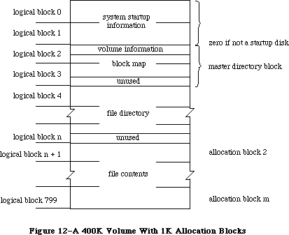 Figure 12–A 400K Volume With 1K Allocation Blocks
The master directory “block” always occupies two blocks—the Disk Initialization Package varies the allocation block size as necessary to achieve this constraint.
The file directory begins in the next logical block following the block map; it contains descriptions and locations of all the files on the volume. The rest of the logical blocks on the volume contain files or garbage (such as parts of deleted files). The exact format of the volume information, volume allocation block map, and file directory is explained in the following sections.
»Volume Information
The volume information is contained in the first 64 bytes of the master directory block (see Figure 13). This information is written on the volume when it’s initialized, and modified thereafter by the File Manager.
Figure 12–A 400K Volume With 1K Allocation Blocks
The master directory “block” always occupies two blocks—the Disk Initialization Package varies the allocation block size as necessary to achieve this constraint.
The file directory begins in the next logical block following the block map; it contains descriptions and locations of all the files on the volume. The rest of the logical blocks on the volume contain files or garbage (such as parts of deleted files). The exact format of the volume information, volume allocation block map, and file directory is explained in the following sections.
»Volume Information
The volume information is contained in the first 64 bytes of the master directory block (see Figure 13). This information is written on the volume when it’s initialized, and modified thereafter by the File Manager.
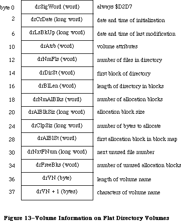 Figure 13–Volume Information on Flat Directory Volumes
DrAtrb contains the volume attributes, as follows:
Bit Meaning
7 Set if volume is locked by hardware
15 Set if volume is locked by software
DrClpSiz contains the minimum number of bytes to allocate each time the Allocate function is called, to minimize fragmentation of files; it’s always a multiple of the allocation block size. DrNxtFNum contains the next unused file number (see the “File Directory” section below for an explanation of file numbers).
»Volume Allocation Block Map
The volume allocation block map represents every allocation block on the volume with a 12-bit entry indicating whether the block is unused or allocated to a file. It begins in the master directory block at the byte following the volume information, and continues for as many logical blocks as needed.
The first entry in the block map is for block number 2; the block map doesn’t contain entries for the system startup blocks. Each entry specifies whether the block is unused, whether it’s the last block in the file, or which allocation block is next in the file:
Entry Meaning
0 Block is unused
1 Block is the last block of the file
2–4095 Number of next block in the file
For instance, assume that there’s one file on the volume, stored in allocation blocks 8, 11, 12, and 17; the first 16 entries of the block map would read
0 0 0 0 0 0 11 0 0 12 17 0 0 0 0 1
The first allocation block on a volume typically follows the file directory.
It’s numbered 2 because of the special meaning of numbers 0 and 1.
Note: As explained below, it’s possible to begin the allocation blocks
immediately following the master directory block and place the file
directory somewhere within the allocation blocks. In this case, the
allocation blocks occupied by the file directory must be marked with
$FFF’s in the allocation block map.
»Flat File Directory
The file directory contains an entry for each file. Each entry lists information about one file on the volume, including its name and location. Each file is listed by its own unique file number, which the File Manager uses to distinguish it from other files on the volume.
A file directory entry contains 51 bytes plus one byte for each character in the file name. If the file names average 20 characters, a directory can hold seven file entries per logical block. Entries are always an integral number of words and don’t cross logical block boundaries. The length of a file directory depends on the maximum number of files the volume can contain; for example, on a 400K volume the file directory occupies 12 logical blocks.
The file directory conventionally follows the block map and precedes the allocation blocks, but a volume-initializing program could actually place the file directory anywhere within the allocation blocks as long as the blocks occupied by the file directory are marked with $FFF’s in the block map.
The format of a file directory entry is shown in Figure 14.
Figure 13–Volume Information on Flat Directory Volumes
DrAtrb contains the volume attributes, as follows:
Bit Meaning
7 Set if volume is locked by hardware
15 Set if volume is locked by software
DrClpSiz contains the minimum number of bytes to allocate each time the Allocate function is called, to minimize fragmentation of files; it’s always a multiple of the allocation block size. DrNxtFNum contains the next unused file number (see the “File Directory” section below for an explanation of file numbers).
»Volume Allocation Block Map
The volume allocation block map represents every allocation block on the volume with a 12-bit entry indicating whether the block is unused or allocated to a file. It begins in the master directory block at the byte following the volume information, and continues for as many logical blocks as needed.
The first entry in the block map is for block number 2; the block map doesn’t contain entries for the system startup blocks. Each entry specifies whether the block is unused, whether it’s the last block in the file, or which allocation block is next in the file:
Entry Meaning
0 Block is unused
1 Block is the last block of the file
2–4095 Number of next block in the file
For instance, assume that there’s one file on the volume, stored in allocation blocks 8, 11, 12, and 17; the first 16 entries of the block map would read
0 0 0 0 0 0 11 0 0 12 17 0 0 0 0 1
The first allocation block on a volume typically follows the file directory.
It’s numbered 2 because of the special meaning of numbers 0 and 1.
Note: As explained below, it’s possible to begin the allocation blocks
immediately following the master directory block and place the file
directory somewhere within the allocation blocks. In this case, the
allocation blocks occupied by the file directory must be marked with
$FFF’s in the allocation block map.
»Flat File Directory
The file directory contains an entry for each file. Each entry lists information about one file on the volume, including its name and location. Each file is listed by its own unique file number, which the File Manager uses to distinguish it from other files on the volume.
A file directory entry contains 51 bytes plus one byte for each character in the file name. If the file names average 20 characters, a directory can hold seven file entries per logical block. Entries are always an integral number of words and don’t cross logical block boundaries. The length of a file directory depends on the maximum number of files the volume can contain; for example, on a 400K volume the file directory occupies 12 logical blocks.
The file directory conventionally follows the block map and precedes the allocation blocks, but a volume-initializing program could actually place the file directory anywhere within the allocation blocks as long as the blocks occupied by the file directory are marked with $FFF’s in the block map.
The format of a file directory entry is shown in Figure 14.
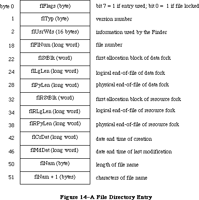 Figure 14–A File Directory Entry
FlStBlk and flRStBlk are 0 if the data or resource fork doesn’t exist. FlCrDat and flMdDat are given in seconds since midnight, January 1, 1904.
Each time a new file is created, an entry for the new file is placed in the file directory. Each time a file is deleted, its entry in the file directory is cleared, and all blocks used by that file on the volume are released.
_______________________________________________________________________________
»Hierarchical Directory Volumes
A hierarchical directory volume contains system startup information in logical blocks 0 and 1 (see Figure 15) that’s read in at system startup. This information is similar to the system startup information for flat directory volumes; it consists of certain configurable system parameters, such as the capacity of the event queue, the initial size of the system heap, and the number of open files allowed.
Figure 14–A File Directory Entry
FlStBlk and flRStBlk are 0 if the data or resource fork doesn’t exist. FlCrDat and flMdDat are given in seconds since midnight, January 1, 1904.
Each time a new file is created, an entry for the new file is placed in the file directory. Each time a file is deleted, its entry in the file directory is cleared, and all blocks used by that file on the volume are released.
_______________________________________________________________________________
»Hierarchical Directory Volumes
A hierarchical directory volume contains system startup information in logical blocks 0 and 1 (see Figure 15) that’s read in at system startup. This information is similar to the system startup information for flat directory volumes; it consists of certain configurable system parameters, such as the capacity of the event queue, the initial size of the system heap, and the number of open files allowed.
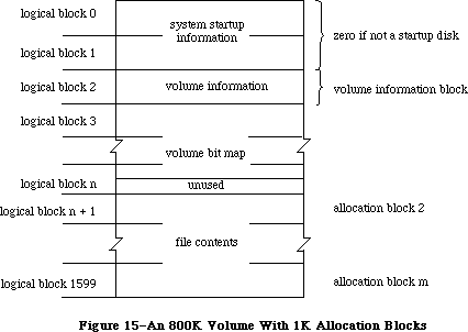 Figure 15–An 800K Volume With 1K Allocation Blocks
Logical block 2 of the volume (also known as the volume information block) contains the volume information. This volume information is a superset of the volume information found on flat directory volumes. Logical block 3 of the volume begins the volume bit map, which records whether each block on the volume is used or unused. The rest of the logical blocks on the volume contain files or garbage (such as parts of deleted files).
The volume bit map on hierarchical directory volumes replaces the volume allocation block map used on flat directory volumes. While the bit map does handle volume space management (as does the block map), it does not handle file mapping. A separate file, known as the extents tree file, performs this function. Finally, a file known as the catalog tree file is responsible for maintaining the hierarchical directory structure; it corresponds in function to the file directory found on flat directory volumes.
The exact format of the volume information, volume bit map, extents tree file, and catalog tree file is explained in the following sections. The discussion of the extents tree and catalog tree files is preceded by a short introduction to a data structure known as a B*-tree that’s used to organize and access the information in these files.
»Volume Information
The volume information is contained in the first 104 bytes of the volume information block (see Figure 16). This information is written on the volume when it’s initialized, and modified thereafter by the File Manager.
Figure 15–An 800K Volume With 1K Allocation Blocks
Logical block 2 of the volume (also known as the volume information block) contains the volume information. This volume information is a superset of the volume information found on flat directory volumes. Logical block 3 of the volume begins the volume bit map, which records whether each block on the volume is used or unused. The rest of the logical blocks on the volume contain files or garbage (such as parts of deleted files).
The volume bit map on hierarchical directory volumes replaces the volume allocation block map used on flat directory volumes. While the bit map does handle volume space management (as does the block map), it does not handle file mapping. A separate file, known as the extents tree file, performs this function. Finally, a file known as the catalog tree file is responsible for maintaining the hierarchical directory structure; it corresponds in function to the file directory found on flat directory volumes.
The exact format of the volume information, volume bit map, extents tree file, and catalog tree file is explained in the following sections. The discussion of the extents tree and catalog tree files is preceded by a short introduction to a data structure known as a B*-tree that’s used to organize and access the information in these files.
»Volume Information
The volume information is contained in the first 104 bytes of the volume information block (see Figure 16). This information is written on the volume when it’s initialized, and modified thereafter by the File Manager.
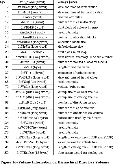 Figure 16–Volume Information on Hierarchical Directory Volumes
64K ROM note: The volume information on a flat directory volume is a
subset of the hierarchical volume information. The flat
directory volume information contains only the fields up
to and including drVN+1. In addition, the names of several
fields have been changed in the hierarchical volume information
to reflect their new function: drLsBkUp, drDirSt, drBlLn,
and drNxtFNum have been changed to drLsMod, drVBMSt, drAllocPtr,
and drNxtCNID respectively. All of the offsets of the flat
directory volume information, however, have been preserved to
maintain compatibility.
DrLsMod contains the date and time that the volume was last modified (this is not necessarily when it was flushed).
64K ROM note: DrLsMod replaces the field drLsBkUp from flat directory
volumes. The name drLsBkUp was actually a misnomer; this
field has always contained the date and time of the last
modification, not the last backup. Another field, drVolBkUp,
contains the date and time of the last backup.
DrVBMSt replaces the field drDirSt; it contains the number of the first block in the volume bit map.
DrAtrb contains the volume attributes, as follows:
Bit Meaning
7 Set if volume is locked by hardware
15 Set if volume is locked by software
DrClpSiz contains the default clump size for the volume. To promote file contiguity and avoid fragmentation, space is allocated to a file not in allocation blocks but in clumps. A clump is a group of contiguous allocation blocks. The clump size is always a multiple of the allocation block size; it’s the minimum number of bytes to allocate each time the Allocate function is called or the end-of-file is reached during the Write routine. A clump size can be set when a particular file is opened, and can also be changed subsequently. If no clump size is specified, the value found in drClpSiz will be used.
DrNxtCNID replaces the field drNxtFNum; it’s either the next file number or the next directory ID to be assigned.
Warning: The format of the volume information may be different in future
versions of Macintosh system software.
»Volume Bit Map
The flat directory file system uses the volume allocation block map to provide both volume space management and file mapping; the hierarchical file system instead uses a volume bit map. The block map contains a 12-bit entry for each allocation block. If an entry is 0, the corresponding allocation block is unused. If an allocation block is allocated to a file, its block map entry is nonzero, and can be used to find the next allocation block used by that file.
The File Manager keeps the entire block map in memory. The size of the block map is obviously a function of the number of allocation blocks on the volume. Similarly, the number of allocation blocks depends on the allocation block size. For larger volumes, the allocation block size must be increased in order to keep the block map to a reasonable size.
A tradeoff occurs between waste of space and speed of file access in this situation. Obviously, the use of large allocation blocks can waste disk space, particularly with small files. On the other hand, using smaller allocation blocks increases the size of the block map; this means the entire block map cannot be kept in memory at one time, resulting in a time-consuming sector-caching scheme.
The hierarchical file system discards the block map concept entirely, and instead uses a structure known as the volume bit map. The bit map has one bit for each allocation block on the volume; if a particular block is in use, its bit is set.
With extremely large volumes, the same space/time tradeoff can become an issue. In general, it’s desirable to set the allocation block size such that the entire bit map can be kept in memory at all times.
»B*-Trees
This section describes the B*-tree implementation used in the extents tree and catalog tree files. The data structures described in this section are accessible only through assembly language; an understanding of the B*-tree data structure is also assumed.
The nodes of a B*-tree contain records; each record consists of certain information (either pointers or data) and a key associated with that information (see Figure 17). A basic feature of the B*-tree is that data is stored only in the leaf nodes. The internal nodes (also known as index nodes) contain pointers to other nodes; they provide an index, used in conjunction with a search key, for accessing the data records stored in the leaf nodes.
Figure 16–Volume Information on Hierarchical Directory Volumes
64K ROM note: The volume information on a flat directory volume is a
subset of the hierarchical volume information. The flat
directory volume information contains only the fields up
to and including drVN+1. In addition, the names of several
fields have been changed in the hierarchical volume information
to reflect their new function: drLsBkUp, drDirSt, drBlLn,
and drNxtFNum have been changed to drLsMod, drVBMSt, drAllocPtr,
and drNxtCNID respectively. All of the offsets of the flat
directory volume information, however, have been preserved to
maintain compatibility.
DrLsMod contains the date and time that the volume was last modified (this is not necessarily when it was flushed).
64K ROM note: DrLsMod replaces the field drLsBkUp from flat directory
volumes. The name drLsBkUp was actually a misnomer; this
field has always contained the date and time of the last
modification, not the last backup. Another field, drVolBkUp,
contains the date and time of the last backup.
DrVBMSt replaces the field drDirSt; it contains the number of the first block in the volume bit map.
DrAtrb contains the volume attributes, as follows:
Bit Meaning
7 Set if volume is locked by hardware
15 Set if volume is locked by software
DrClpSiz contains the default clump size for the volume. To promote file contiguity and avoid fragmentation, space is allocated to a file not in allocation blocks but in clumps. A clump is a group of contiguous allocation blocks. The clump size is always a multiple of the allocation block size; it’s the minimum number of bytes to allocate each time the Allocate function is called or the end-of-file is reached during the Write routine. A clump size can be set when a particular file is opened, and can also be changed subsequently. If no clump size is specified, the value found in drClpSiz will be used.
DrNxtCNID replaces the field drNxtFNum; it’s either the next file number or the next directory ID to be assigned.
Warning: The format of the volume information may be different in future
versions of Macintosh system software.
»Volume Bit Map
The flat directory file system uses the volume allocation block map to provide both volume space management and file mapping; the hierarchical file system instead uses a volume bit map. The block map contains a 12-bit entry for each allocation block. If an entry is 0, the corresponding allocation block is unused. If an allocation block is allocated to a file, its block map entry is nonzero, and can be used to find the next allocation block used by that file.
The File Manager keeps the entire block map in memory. The size of the block map is obviously a function of the number of allocation blocks on the volume. Similarly, the number of allocation blocks depends on the allocation block size. For larger volumes, the allocation block size must be increased in order to keep the block map to a reasonable size.
A tradeoff occurs between waste of space and speed of file access in this situation. Obviously, the use of large allocation blocks can waste disk space, particularly with small files. On the other hand, using smaller allocation blocks increases the size of the block map; this means the entire block map cannot be kept in memory at one time, resulting in a time-consuming sector-caching scheme.
The hierarchical file system discards the block map concept entirely, and instead uses a structure known as the volume bit map. The bit map has one bit for each allocation block on the volume; if a particular block is in use, its bit is set.
With extremely large volumes, the same space/time tradeoff can become an issue. In general, it’s desirable to set the allocation block size such that the entire bit map can be kept in memory at all times.
»B*-Trees
This section describes the B*-tree implementation used in the extents tree and catalog tree files. The data structures described in this section are accessible only through assembly language; an understanding of the B*-tree data structure is also assumed.
The nodes of a B*-tree contain records; each record consists of certain information (either pointers or data) and a key associated with that information (see Figure 17). A basic feature of the B*-tree is that data is stored only in the leaf nodes. The internal nodes (also known as index nodes) contain pointers to other nodes; they provide an index, used in conjunction with a search key, for accessing the data records stored in the leaf nodes.
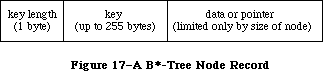 Figure 17–A B*-Tree Node Record
Within each node, the records are maintained so that their keys are in ascending order. Figure 18 shows a sample B*-tree; hypothetical keys have been inserted to illustrate the structure of the tree and the relationship between index and leaf nodes.
Figure 17–A B*-Tree Node Record
Within each node, the records are maintained so that their keys are in ascending order. Figure 18 shows a sample B*-tree; hypothetical keys have been inserted to illustrate the structure of the tree and the relationship between index and leaf nodes.
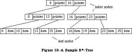 Figure 18–A Sample B*-Tree
When a data record is needed, the key of the desired record (the search key) is provided. The search begins at the root node (which is an index node, unless the tree has only one level), moving from one record to the next until the record with the highest key that’s less than or equal to the search key is reached. The pointer of that record leads to another node, one level down in the tree. This process continues until a leaf node is reached; its records are examined until the desired key is found. (The desired key may not be found; in this case, the search stops when a key larger than the search key is reached.) Figure 19 shows a sample B*-tree search path; the arrows indicate the path to the second record in the second leaf node.
Figure 18–A Sample B*-Tree
When a data record is needed, the key of the desired record (the search key) is provided. The search begins at the root node (which is an index node, unless the tree has only one level), moving from one record to the next until the record with the highest key that’s less than or equal to the search key is reached. The pointer of that record leads to another node, one level down in the tree. This process continues until a leaf node is reached; its records are examined until the desired key is found. (The desired key may not be found; in this case, the search stops when a key larger than the search key is reached.) Figure 19 shows a sample B*-tree search path; the arrows indicate the path to the second record in the second leaf node.
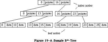 Figure 19–A Sample B*-Tree Search Path
All nodes in the B*-tree are of the same fixed size; the structure of a node is shown in Figure 20.
Figure 19–A Sample B*-Tree Search Path
All nodes in the B*-tree are of the same fixed size; the structure of a node is shown in Figure 20.
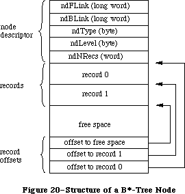 Figure 20–Structure of a B*-Tree Node
Each node begins with the node descriptor. NDNRecs contains the number of records currently in the node. NDType indicates the type of node; it contains $FF if it’s a leaf node and 0 if it’s an index node. NDLevel indicates the level of the node in the tree; leaf nodes are always at level 1, the first level of index nodes above them are at level 2, and so on.
NDBLink and ndFLink are used only with leaf nodes as a way of quickly moving through the data records; for each leaf node, they contain pointers to the previous and subsequent leaf nodes respectively.
The records in a node can be of variable length; for this reason, offsets to the beginning of each record are needed. The records begin after the field ndNRecs; they’re followed by the unused space. The offsets to the records begin at the end of the node and work backwards; they’re followed by an offset to the unused space.
»Extents Tree File
File mapping information (or the location of a file’s data on the volume) is contained in the extents tree file. A file extent is a series of contiguous allocation blocks. Ideally, a file would be stored in a single extent. Except in the case of preallocated or small files, however, the contents of a particular file are usually stored in more than one extent on different parts of a given volume. The extents tree file, organized as a B*-tree, records the volume location and size of the various extents that comprise a file.
Each extent on a volume is identified by an extent descriptor; each descriptor consists of the number of the first allocation block of the extent followed by the length of the extent in blocks (see Figure 21).
Figure 20–Structure of a B*-Tree Node
Each node begins with the node descriptor. NDNRecs contains the number of records currently in the node. NDType indicates the type of node; it contains $FF if it’s a leaf node and 0 if it’s an index node. NDLevel indicates the level of the node in the tree; leaf nodes are always at level 1, the first level of index nodes above them are at level 2, and so on.
NDBLink and ndFLink are used only with leaf nodes as a way of quickly moving through the data records; for each leaf node, they contain pointers to the previous and subsequent leaf nodes respectively.
The records in a node can be of variable length; for this reason, offsets to the beginning of each record are needed. The records begin after the field ndNRecs; they’re followed by the unused space. The offsets to the records begin at the end of the node and work backwards; they’re followed by an offset to the unused space.
»Extents Tree File
File mapping information (or the location of a file’s data on the volume) is contained in the extents tree file. A file extent is a series of contiguous allocation blocks. Ideally, a file would be stored in a single extent. Except in the case of preallocated or small files, however, the contents of a particular file are usually stored in more than one extent on different parts of a given volume. The extents tree file, organized as a B*-tree, records the volume location and size of the various extents that comprise a file.
Each extent on a volume is identified by an extent descriptor; each descriptor consists of the number of the first allocation block of the extent followed by the length of the extent in blocks (see Figure 21).
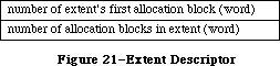 Figure 21–Extent Descriptor
The extent descriptors are stored in extent records in the leaf nodes of the tree. Each extent record consists of a key followed by three extent descriptors. The extent records are kept sorted by the key, which has the format shown in Figure 22.
Figure 21–Extent Descriptor
The extent descriptors are stored in extent records in the leaf nodes of the tree. Each extent record consists of a key followed by three extent descriptors. The extent records are kept sorted by the key, which has the format shown in Figure 22.
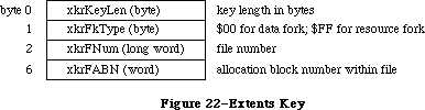 Figure 22–Extents Key
»Catalog Tree File
The catalog tree file corresponds in function to the flat file directory found on volumes formatted by the 64K ROM. Whereas a flat file directory contains entries for files only, the catalog tree file contains three types of records—file records, directory records, and thread records. (Threads can be viewed as the branches connecting the nodes of a catalog tree.) The catalog tree file is organized as a B*-tree; all three types of records are stored in the leaf nodes. The index nodes contain the index records used to search through the tree.
The catalog tree records consist of a key followed by the file, directory, or thread record. The records are kept sorted by key. The exact format of the key is shown in Figure 23.
Figure 22–Extents Key
»Catalog Tree File
The catalog tree file corresponds in function to the flat file directory found on volumes formatted by the 64K ROM. Whereas a flat file directory contains entries for files only, the catalog tree file contains three types of records—file records, directory records, and thread records. (Threads can be viewed as the branches connecting the nodes of a catalog tree.) The catalog tree file is organized as a B*-tree; all three types of records are stored in the leaf nodes. The index nodes contain the index records used to search through the tree.
The catalog tree records consist of a key followed by the file, directory, or thread record. The records are kept sorted by key. The exact format of the key is shown in Figure 23.
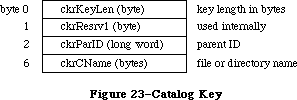 Figure 23–Catalog Key
A file record is a superset of the file directory entry found on volumes formatted by the 64K ROM; its contents are shown in Figure 24.
Figure 23–Catalog Key
A file record is a superset of the file directory entry found on volumes formatted by the 64K ROM; its contents are shown in Figure 24.
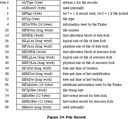 Figure 24–File Record
A directory record records information about a single directory; the format of a directory record is shown in Figure 25.
Figure 24–File Record
A directory record records information about a single directory; the format of a directory record is shown in Figure 25.
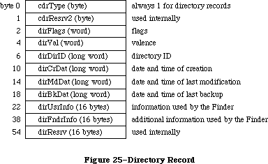 Figure 25–Directory Record
Thread records are used in conjunction with directory records to provide a link between a given directory and its parent. For any given directory, the records describing all of its offspring are stored contiguously. A thread record precedes each set of offspring; it contains the directory ID and name of the parent and provides a path to the parent’s directory record. The format of a thread record is shown in Figure 26.
Figure 25–Directory Record
Thread records are used in conjunction with directory records to provide a link between a given directory and its parent. For any given directory, the records describing all of its offspring are stored contiguously. A thread record precedes each set of offspring; it contains the directory ID and name of the parent and provides a path to the parent’s directory record. The format of a thread record is shown in Figure 26.
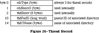 Figure 26–Thread Record
A portion of a sample tree, along with the corresponding file, directory, and thread records, is shown in Figure 27.
Figure 26–Thread Record
A portion of a sample tree, along with the corresponding file, directory, and thread records, is shown in Figure 27.
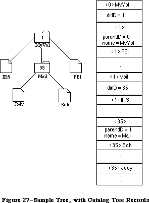 Figure 27–Sample Tree, with Catalog Tree Records
_______________________________________________________________________________
»DATA STRUCTURES IN MEMORY
_______________________________________________________________________________
This section describes the memory data structures used by the File Manager and any external file system that accesses files on Macintosh-initialized volumes. Some of this data is accessible only through assembly language.
The data structures in memory used by the File Manager and all external file systems include:
• the file I/O queue, listing all asynchronous routines awaiting
execution (including the currently executing routine, if any)
• the volume-control-block queue, listing information about each
mounted volume
• a copy of the volume bit map for each on-line volume (volume
allocation block map for flat directory volumes)
• the file-control-block buffer, listing information about each access path
• volume buffers (one for each on-line volume)
• optional access path buffers (one for each access path)
• the drive queue, listing information about each drive connected
to the Macintosh
_______________________________________________________________________________
»The File I/O Queue
The file I/O queue is a standard Operating System queue (described in the Operating System Utilities chapter) that contains parameter blocks for all asynchronous routines awaiting execution. Each time a routine is called, an entry is placed in the queue; each time a routine is completed, its entry is removed from the queue.
Each entry in the file I/O queue consists of a parameter block for the routine that was called. Most of the fields of this parameter block contain information needed by the specific File Manager routines; these fields are explained above in the section “Low-Level File Manager Routines”. The first four fields of the parameter block, shown below, are used by the File Manager in processing the
I/O requests in the queue.
TYPE ParamBlockRec = RECORD
qLink: QElemPtr; {next queue entry}
qType: INTEGER; {queue type}
ioTrap: INTEGER; {routine trap}
ioCmdAddr: Ptr; {routine address}
. . . {rest of block}
END;
QLink points to the next entry in the queue, and qType indicates the queue type, which must always be ORD(ioQType). IOTrap and ioCmdAddr contain the trap word and address of the File Manager routine that was called.
You can get a pointer to the header of the file I/O queue by calling the File Manager function GetFSQHdr.
FUNCTION GetFSQHdr : QHdrPtr; [Not in ROM]
GetFSQHdr returns a pointer to the header of the file I/O queue.
Assembly-language note: The global variable FSQHdr contains the
header of the file I/O queue.
_______________________________________________________________________________
»Volume Control Blocks
X-Ref: Technical Note #106
Each time a volume is mounted, its volume information is read from it and is used to build a new volume control block in the volume-control-block queue
(unless an ejected or off-line volume is being remounted). A copy of the volume block map is also read from the volume and placed in the system heap, and a volume buffer is created in the system heap.
The volume-control-block queue is a standard Operating System queue that’s maintained in the system heap. It contains a volume control block for each mounted volume. A volume control block is a 178-byte nonrelocatable block that contains volume-specific information. It has the following structure:
TYPE VCB = RECORD
qLink: QElemPtr; {next queue entry}
qType: INTEGER; {queue type}
vcbFlags: INTEGER; {bit 15=1 if dirty}
vcbSigWord: INTEGER; {$4244 for hierarchical, $D2D7 for flat}
vcbCrDate: LONGINT; {date and time of initialization}
vcbLsMod: LONGINT; {date and time of last modification}
vcbAtrb: INTEGER; {volume attributes}
vcbNmFls: INTEGER; {number of files in directory}
vcbVBMSt: INTEGER; {first block of volume bit map}
vcbAllocPtr: INTEGER; {used internally}
vcbNmAlBlks: INTEGER; {number of allocation blocks}
vcbAlBlkSiz: LONGINT; {allocation block size}
vcbClpSiz: LONGINT; {default clump size}
vcbAlBlSt: INTEGER; {first block in block map}
vcbNxtCNID: LONGINT; {next unused directory ID or file number}
vcbFreeBks: INTEGER; {number of unused allocation blocks}
vcbVN: STRING[27]; {volume name}
vcbDrvNum: INTEGER; {drive number}
vcbDRefNum: INTEGER; {driver reference number}
vcbFSID: INTEGER; {file-system identifier}
vcbVRefNum: INTEGER; {volume reference number}
vcbMAdr: Ptr; {pointer to block map}
vcbBufAdr: Ptr; {pointer to volume buffer}
vcbMLen: INTEGER; {number of bytes in block map}
vcbDirIndex: INTEGER; {used internally}
vcbDirBlk: INTEGER; {used internally}
vcbVolBkUp: LONGINT; {date and time of last backup}
vcbVSeqNum: INTEGER; {used internally}
vcbWrCnt: LONGINT; {volume write count}
vcbXTClpSiz: LONGINT; {clump size of extents tree file}
vcbCTClpSiz: LONGINT; {clump size of catalog tree file}
vcbNmRtDirs: INTEGER; {number of directories in root}
vcbFilCnt: LONGINT; {number of files on volume}
vcbDirCnt: LONGINT; {number of directories on volume}
vcbFndrInfo: ARRAY[1..8] OF LONGINT; {information used by }
{ the Finder}
vcbVCSize: INTEGER; {used internally}
vcbVBMCSiz: INTEGER; {used internally}
vcbCtlCSiz: INTEGER; {used internally}
vcbXTAlBks: INTEGER; {size in blocks of extents tree file}
vcbCTAlBks: INTEGER; {size in blocks of catalog tree file}
vcbXTRef: INTEGER; {path reference number for extents }
{ tree file}
vcbCTRef: INTEGER; {path reference number for catalog }
{ tree file}
vcbCtlBuf: Ptr; {pointer to extents and catalog }
{ tree caches}
vcbDirIDM: LONGINT; {directory last searched}
vcbOffsM: INTEGER {offspring index at last search}
END;
64K ROM note: A volume control block created for a flat volume is a subset
of the above structure. It’s actually smaller and contains
only the fields up to and including vcbDirBlk. In addition,
the names of several fields have been changed to reflect the
fact that they contain different information on hierarchical
volumes: vcbLsBkUp, vcbDirSt, vcbBlLn, vcbNmBlks, and
vcbNxtFNum have been changed to vcbLsMod, vcbVBMSt,
vcbAllocPtr, vcbNmAlBlks, and vcbNxtCNID respectively.
QLink points to the next entry in the queue, and qType indicates the queue type, which must always be ORD(fsQType). Bit 15 of vcbFlags is set if the volume information has been changed by a routine call since the volume was last affected by a FlushVol call.
VCBLsMod contains the date and time that the volume was last modified (this is not necessarily when it was flushed).
64K ROM note: VCBLsMod replaces the field vcbLsBkUp from flat directory
volumes. The name vcbLsBkUp was actually a misnomer; this
field has always contained the date and time of the last
modification, not the last backup. Another field, vcbVolBkUp,
contains the date and time of the last backup.
VCBAtrb contains the volume attributes, as follows:
Bit Meaning
0–4 Set if inconsistencies were found between the volume
information and the file directory when the volume was mounted
6 Set if volume is busy (one or more files are open)
7 Set if volume is locked by hardware
15 Set if volume is locked by software
VCBVBMSt contains the number of the first block in the volume bit map; on flat volumes, it contains the first block of the file directory. VCBNmAlBlks contains the number of allocation blocks on the volume, and vcbFreeBks specifies how many of those blocks are unused. VCBAlBlSt is used only with flat volumes; it contains the number of the first block in the block map.
VCBDrvNum contains the drive number of the drive on which the volume is mounted; vcbDRefNum contains the driver reference number of the driver used to access the volume. When a mounted volume is placed off-line, vcbDrvNum is cleared. When a volume is ejected, vcbDrvNum is cleared and vcbDRefNum is set to the negative of vcbDrvNum (becoming a positive number). VCBFSID identifies the file system handling the volume; it’s 0 for volumes handled by the File Manager, and nonzero for volumes handled by other file systems.
When a volume is placed off-line, its buffer and bit map (or block map, in the case of flat directory volumes) are released. When a volume is unmounted, its volume control block is removed from the volume-control-block queue.
You can get a pointer to the header of the volume-control-block queue by calling the File Manager function GetVCBQHdr.
FUNCTION GetVCBQHdr : QHdrPtr; [Not in ROM]
GetVCBQHdr returns a pointer to the header of the volume-control-block queue.
Assembly-language note: The global variable VCBQHdr contains the header
of the volume-control-block-queue. The default
volume’s volume control block is pointed to by
the global variable DefVCBPtr.
_______________________________________________________________________________
»File Control Blocks
X-Ref: Technical Note #87
Each time a file is opened, the file’s directory entry is used to build a file control block in the file-control-block buffer, which contains information about all access paths. The file-control-block-buffer is a nonrelocatable block in the system heap; the first word contains the length of the buffer.
The number of file control blocks is contained in the system startup information on a volume. With the 64K ROM, the standard number is 12 file control blocks on a Macintosh 128K and 48 file control blocks on the Macintosh 512K. With the 128K ROM, there’s a standard of 40 file control blocks per volume.
Each open fork of a file requires one access path. Two access paths are used for the system and application resource files (whose resource forks are always open). On hierarchical directory volumes, two access paths are also needed for the extents and catalog trees. You should keep such files in mind when calculating the number of files that can be opened by your application.
Note: The size of the file-control-block buffer is determined by
the system startup information stored on a volume.
You can get information from the file control block allocated for an open file by calling the File Manager function PBGetFCBInfo. When you call PBGetFCBInfo, you’ll use the following 12 additional fields after the standard eight fields in the parameter block record FCBPBRec:
ioRefNum: INTEGER; {path reference number}
filler: INTEGER; {not used}
ioFCBIndx: LONGINT; {FCB index}
ioFCBFlNm: LONGINT; {file number}
ioFCBFlags: INTEGER; {flags}
ioFCBStBlk: INTEGER; {first allocation block of file}
ioFCBEOF: LONGINT; {logical end-of-file}
ioFCBPLen: LONGINT; {physical end-of-file}
ioFCBCrPs: LONGINT; {mark}
ioFCBVRefNum: INTEGER; {volume reference number}
ioFCBClpSiz: LONGINT; {file clump size}
ioFCBParID: LONGINT; {parent directory ID}
FUNCTION PBGetFCBInfo (paramBlock: FCBPBPtr; async: BOOLEAN) : OSErr;
Trap macro _GetFCBInfo
Parameter block
--> 12 ioCompletion pointer
<-- 16 ioResult word
<-- 18 ioNamePtr pointer
<-> 22 ioVRefNum word
<-> 24 ioRefNum word
--> 28 ioFCBIndx long word
<-- 32 ioFCBFlNm long word
<-- 36 ioFCBFlags word
<-- 38 ioFCBStBlk word
<-- 40 ioFCBEOF long word
<-- 44 ioFCBPLen long word
<-- 48 ioFCBCrPs long word
<-- 52 ioFCBVRefNum word
<-- 54 ioFCBClpSiz long word
<-- 58 ioFCBParID long word
PBGetFCBInfo returns information about the specified open file. If ioFCBIndx is positive, the File Manager returns information about the file whose file number is ioFCBIndx on the volume specified by ioVRefNum (which may contain a drive number, volume reference number, or working directory reference number). If ioVRefNum is 0, all open files are indexed; otherwise, only open files on the specified volume are indexed.
If ioFCBIndx is 0, the File Manager returns information about the file whose access path is specified by ioRefNum.
Assembly-language note: The global variable FCBSPtr points to the
length word of the file-control-block buffer.
Each file control block contains 94 bytes of information about an access path; Figure 28 shows its structure (using the assembly-language offsets).
Figure 27–Sample Tree, with Catalog Tree Records
_______________________________________________________________________________
»DATA STRUCTURES IN MEMORY
_______________________________________________________________________________
This section describes the memory data structures used by the File Manager and any external file system that accesses files on Macintosh-initialized volumes. Some of this data is accessible only through assembly language.
The data structures in memory used by the File Manager and all external file systems include:
• the file I/O queue, listing all asynchronous routines awaiting
execution (including the currently executing routine, if any)
• the volume-control-block queue, listing information about each
mounted volume
• a copy of the volume bit map for each on-line volume (volume
allocation block map for flat directory volumes)
• the file-control-block buffer, listing information about each access path
• volume buffers (one for each on-line volume)
• optional access path buffers (one for each access path)
• the drive queue, listing information about each drive connected
to the Macintosh
_______________________________________________________________________________
»The File I/O Queue
The file I/O queue is a standard Operating System queue (described in the Operating System Utilities chapter) that contains parameter blocks for all asynchronous routines awaiting execution. Each time a routine is called, an entry is placed in the queue; each time a routine is completed, its entry is removed from the queue.
Each entry in the file I/O queue consists of a parameter block for the routine that was called. Most of the fields of this parameter block contain information needed by the specific File Manager routines; these fields are explained above in the section “Low-Level File Manager Routines”. The first four fields of the parameter block, shown below, are used by the File Manager in processing the
I/O requests in the queue.
TYPE ParamBlockRec = RECORD
qLink: QElemPtr; {next queue entry}
qType: INTEGER; {queue type}
ioTrap: INTEGER; {routine trap}
ioCmdAddr: Ptr; {routine address}
. . . {rest of block}
END;
QLink points to the next entry in the queue, and qType indicates the queue type, which must always be ORD(ioQType). IOTrap and ioCmdAddr contain the trap word and address of the File Manager routine that was called.
You can get a pointer to the header of the file I/O queue by calling the File Manager function GetFSQHdr.
FUNCTION GetFSQHdr : QHdrPtr; [Not in ROM]
GetFSQHdr returns a pointer to the header of the file I/O queue.
Assembly-language note: The global variable FSQHdr contains the
header of the file I/O queue.
_______________________________________________________________________________
»Volume Control Blocks
X-Ref: Technical Note #106
Each time a volume is mounted, its volume information is read from it and is used to build a new volume control block in the volume-control-block queue
(unless an ejected or off-line volume is being remounted). A copy of the volume block map is also read from the volume and placed in the system heap, and a volume buffer is created in the system heap.
The volume-control-block queue is a standard Operating System queue that’s maintained in the system heap. It contains a volume control block for each mounted volume. A volume control block is a 178-byte nonrelocatable block that contains volume-specific information. It has the following structure:
TYPE VCB = RECORD
qLink: QElemPtr; {next queue entry}
qType: INTEGER; {queue type}
vcbFlags: INTEGER; {bit 15=1 if dirty}
vcbSigWord: INTEGER; {$4244 for hierarchical, $D2D7 for flat}
vcbCrDate: LONGINT; {date and time of initialization}
vcbLsMod: LONGINT; {date and time of last modification}
vcbAtrb: INTEGER; {volume attributes}
vcbNmFls: INTEGER; {number of files in directory}
vcbVBMSt: INTEGER; {first block of volume bit map}
vcbAllocPtr: INTEGER; {used internally}
vcbNmAlBlks: INTEGER; {number of allocation blocks}
vcbAlBlkSiz: LONGINT; {allocation block size}
vcbClpSiz: LONGINT; {default clump size}
vcbAlBlSt: INTEGER; {first block in block map}
vcbNxtCNID: LONGINT; {next unused directory ID or file number}
vcbFreeBks: INTEGER; {number of unused allocation blocks}
vcbVN: STRING[27]; {volume name}
vcbDrvNum: INTEGER; {drive number}
vcbDRefNum: INTEGER; {driver reference number}
vcbFSID: INTEGER; {file-system identifier}
vcbVRefNum: INTEGER; {volume reference number}
vcbMAdr: Ptr; {pointer to block map}
vcbBufAdr: Ptr; {pointer to volume buffer}
vcbMLen: INTEGER; {number of bytes in block map}
vcbDirIndex: INTEGER; {used internally}
vcbDirBlk: INTEGER; {used internally}
vcbVolBkUp: LONGINT; {date and time of last backup}
vcbVSeqNum: INTEGER; {used internally}
vcbWrCnt: LONGINT; {volume write count}
vcbXTClpSiz: LONGINT; {clump size of extents tree file}
vcbCTClpSiz: LONGINT; {clump size of catalog tree file}
vcbNmRtDirs: INTEGER; {number of directories in root}
vcbFilCnt: LONGINT; {number of files on volume}
vcbDirCnt: LONGINT; {number of directories on volume}
vcbFndrInfo: ARRAY[1..8] OF LONGINT; {information used by }
{ the Finder}
vcbVCSize: INTEGER; {used internally}
vcbVBMCSiz: INTEGER; {used internally}
vcbCtlCSiz: INTEGER; {used internally}
vcbXTAlBks: INTEGER; {size in blocks of extents tree file}
vcbCTAlBks: INTEGER; {size in blocks of catalog tree file}
vcbXTRef: INTEGER; {path reference number for extents }
{ tree file}
vcbCTRef: INTEGER; {path reference number for catalog }
{ tree file}
vcbCtlBuf: Ptr; {pointer to extents and catalog }
{ tree caches}
vcbDirIDM: LONGINT; {directory last searched}
vcbOffsM: INTEGER {offspring index at last search}
END;
64K ROM note: A volume control block created for a flat volume is a subset
of the above structure. It’s actually smaller and contains
only the fields up to and including vcbDirBlk. In addition,
the names of several fields have been changed to reflect the
fact that they contain different information on hierarchical
volumes: vcbLsBkUp, vcbDirSt, vcbBlLn, vcbNmBlks, and
vcbNxtFNum have been changed to vcbLsMod, vcbVBMSt,
vcbAllocPtr, vcbNmAlBlks, and vcbNxtCNID respectively.
QLink points to the next entry in the queue, and qType indicates the queue type, which must always be ORD(fsQType). Bit 15 of vcbFlags is set if the volume information has been changed by a routine call since the volume was last affected by a FlushVol call.
VCBLsMod contains the date and time that the volume was last modified (this is not necessarily when it was flushed).
64K ROM note: VCBLsMod replaces the field vcbLsBkUp from flat directory
volumes. The name vcbLsBkUp was actually a misnomer; this
field has always contained the date and time of the last
modification, not the last backup. Another field, vcbVolBkUp,
contains the date and time of the last backup.
VCBAtrb contains the volume attributes, as follows:
Bit Meaning
0–4 Set if inconsistencies were found between the volume
information and the file directory when the volume was mounted
6 Set if volume is busy (one or more files are open)
7 Set if volume is locked by hardware
15 Set if volume is locked by software
VCBVBMSt contains the number of the first block in the volume bit map; on flat volumes, it contains the first block of the file directory. VCBNmAlBlks contains the number of allocation blocks on the volume, and vcbFreeBks specifies how many of those blocks are unused. VCBAlBlSt is used only with flat volumes; it contains the number of the first block in the block map.
VCBDrvNum contains the drive number of the drive on which the volume is mounted; vcbDRefNum contains the driver reference number of the driver used to access the volume. When a mounted volume is placed off-line, vcbDrvNum is cleared. When a volume is ejected, vcbDrvNum is cleared and vcbDRefNum is set to the negative of vcbDrvNum (becoming a positive number). VCBFSID identifies the file system handling the volume; it’s 0 for volumes handled by the File Manager, and nonzero for volumes handled by other file systems.
When a volume is placed off-line, its buffer and bit map (or block map, in the case of flat directory volumes) are released. When a volume is unmounted, its volume control block is removed from the volume-control-block queue.
You can get a pointer to the header of the volume-control-block queue by calling the File Manager function GetVCBQHdr.
FUNCTION GetVCBQHdr : QHdrPtr; [Not in ROM]
GetVCBQHdr returns a pointer to the header of the volume-control-block queue.
Assembly-language note: The global variable VCBQHdr contains the header
of the volume-control-block-queue. The default
volume’s volume control block is pointed to by
the global variable DefVCBPtr.
_______________________________________________________________________________
»File Control Blocks
X-Ref: Technical Note #87
Each time a file is opened, the file’s directory entry is used to build a file control block in the file-control-block buffer, which contains information about all access paths. The file-control-block-buffer is a nonrelocatable block in the system heap; the first word contains the length of the buffer.
The number of file control blocks is contained in the system startup information on a volume. With the 64K ROM, the standard number is 12 file control blocks on a Macintosh 128K and 48 file control blocks on the Macintosh 512K. With the 128K ROM, there’s a standard of 40 file control blocks per volume.
Each open fork of a file requires one access path. Two access paths are used for the system and application resource files (whose resource forks are always open). On hierarchical directory volumes, two access paths are also needed for the extents and catalog trees. You should keep such files in mind when calculating the number of files that can be opened by your application.
Note: The size of the file-control-block buffer is determined by
the system startup information stored on a volume.
You can get information from the file control block allocated for an open file by calling the File Manager function PBGetFCBInfo. When you call PBGetFCBInfo, you’ll use the following 12 additional fields after the standard eight fields in the parameter block record FCBPBRec:
ioRefNum: INTEGER; {path reference number}
filler: INTEGER; {not used}
ioFCBIndx: LONGINT; {FCB index}
ioFCBFlNm: LONGINT; {file number}
ioFCBFlags: INTEGER; {flags}
ioFCBStBlk: INTEGER; {first allocation block of file}
ioFCBEOF: LONGINT; {logical end-of-file}
ioFCBPLen: LONGINT; {physical end-of-file}
ioFCBCrPs: LONGINT; {mark}
ioFCBVRefNum: INTEGER; {volume reference number}
ioFCBClpSiz: LONGINT; {file clump size}
ioFCBParID: LONGINT; {parent directory ID}
FUNCTION PBGetFCBInfo (paramBlock: FCBPBPtr; async: BOOLEAN) : OSErr;
Trap macro _GetFCBInfo
Parameter block
--> 12 ioCompletion pointer
<-- 16 ioResult word
<-- 18 ioNamePtr pointer
<-> 22 ioVRefNum word
<-> 24 ioRefNum word
--> 28 ioFCBIndx long word
<-- 32 ioFCBFlNm long word
<-- 36 ioFCBFlags word
<-- 38 ioFCBStBlk word
<-- 40 ioFCBEOF long word
<-- 44 ioFCBPLen long word
<-- 48 ioFCBCrPs long word
<-- 52 ioFCBVRefNum word
<-- 54 ioFCBClpSiz long word
<-- 58 ioFCBParID long word
PBGetFCBInfo returns information about the specified open file. If ioFCBIndx is positive, the File Manager returns information about the file whose file number is ioFCBIndx on the volume specified by ioVRefNum (which may contain a drive number, volume reference number, or working directory reference number). If ioVRefNum is 0, all open files are indexed; otherwise, only open files on the specified volume are indexed.
If ioFCBIndx is 0, the File Manager returns information about the file whose access path is specified by ioRefNum.
Assembly-language note: The global variable FCBSPtr points to the
length word of the file-control-block buffer.
Each file control block contains 94 bytes of information about an access path; Figure 28 shows its structure (using the assembly-language offsets).
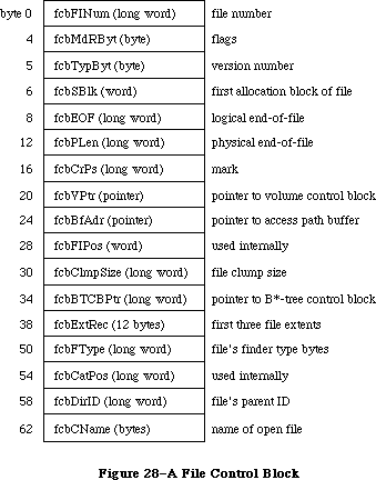 Figure 28–A File Control Block
64K ROM note: The structure of a file control block in the 64K ROM
version of the File Manager is a subset of the above
structure. The old file control block contained only
the fields up to and including fcbFlPos.
FCBMdRByt (which corresponds to ioFCBFlags in the parameter block for PBGetFCBInfo) contains flags that describe the status of the file, as follows:
Bit Meaning
0 Set if data can be written to the file
1 Set if the entry describes a resource fork
7 Set if the file has been changed since it was last flushed
Warning: The size and structure of a file control block may be
different in future versions of Macintosh system software.
_______________________________________________________________________________
»The Drive Queue
X-Ref: Technical Note #36
Disk drives connected to the Macintosh are opened when the system starts up, and information describing each is placed in the drive queue. This is a standard Operating System queue, and each entry in it has the following structure:
TYPE DrvQEl = RECORD
qLink: QElemPtr; {next queue entry}
qType: INTEGER; {queue type}
dQDrive: INTEGER; {drive number}
dQRefNum: INTEGER; {driver reference number}
dQFSID: INTEGER; {file-system identifier}
dQDrvSz: INTEGER; {number of logical blocks on drive}
dQDrvSz2: INTEGER; {additional field to handle large }
{ drive size}
END;
QLink points to the next entry in the queue. If qType is 0, this means the number of logical blocks on the drive is contained in the dQDrvSz field alone. If qType is 1, both dQDrvSz and dQDrvSz2 are used to store the number of blocks; dqDrvSz2 contains the high-order word of this number and dQDrvSz contains the low-order word.
DQDrive contains the drive number of the drive on which the volume is mounted; dQRefNum contains the driver reference number of the driver controlling the device on which the volume is mounted. DQFSID identifies the file system handling the volume in the drive; it’s 0 for volumes handled by the File Manager, and nonzero for volumes handled by other file systems.
Four bytes of flags precede each drive queue entry; they’re accessible only from assembly language.
Assembly-language note: These bytes contain the following:
Byte Contents
0 Bit 7=1 if volume is locked
1 0 if no disk in drive; 1 or 2 if disk
in drive; 8 if nonejectable disk in drive;
$FC-$FF if disk was ejected within last 1.5
seconds; $48 if disk in drive is
nonejectable but driver wants a call
2 Used internally during system startup
3 Bit 7=0 if disk is single-sided
You can get a pointer to the header of the drive queue by calling the File Manager function GetDrvQHdr.
FUNCTION GetDrvQHdr : QHdrPtr; [Not in ROM]
GetDrvQHdr returns a pointer to the header of the drive queue.
Assembly-language note: The global variable DrvQHdr contains the
header of the drive queue.
The drive queue can support any number of drives, limited only by memory space.
_______________________________________________________________________________
»USING AN EXTERNAL FILE SYSTEM
_______________________________________________________________________________
Due to the complexity of writing an external file system for the 128K ROM version of the File Manager, this subject is covered in a separate document. To receive a copy, write to:
Developer Technical Support
Apple Computer, Inc.
20525 Mariani Avenue, M/S 75-3T
Cupertino, CA 95014
_______________________________________________________________________________
»SUMMARY OF THE FILE MANAGER
_______________________________________________________________________________
Constants
CONST
{ Flags in file information used by the Finder }
fOnDesk = 1; {set if file is on desktop (hierarchical volumes only)}
fHasBundle = 8192; {set if file has a bundle}
fInvisible = 16384; {set if file's icon is invisible}
fTrash = -3; {file is in Trash window}
fDesktop = -2; {file is on desktop}
fDisk = 0; {file is in disk window}
{ Values for requesting read/write permission}
fsCurPerm = 0; {whatever is currently allowed}
fsRdPerm = 1; {request for read permission only}
fsWrPerm = 2; {request for write permission only}
fsRdWrPerm = 3; {request for exclusive read/write permission}
fsRdWrShPerm = 4; {request for shared read/write permission}
{ Positioning modes }
fsAtMark = 0; {at current mark}
fsFromStart = 1; {set mark relative to beginning of file}
fsFromLEOF = 2; {set mark relative to logical end-of-file}
fsFromMark = 3; {set mark relative to current mark}
rdVerify = 64; {add to above for read-verify}
; Bits in vMAttrib about the volume
bHasNewDesk .EQU 12 ;If set, all of the new desktop calls are
; supported (for example, OpenDB, AddIco,
; AddComment).
bHasMoveRename .EQU 13 ;If set, _MoveRename call supported.
bHasCopyFile .EQU 14 ;If set, _CopyFile call supported.
; _CopyFile is used in copy and duplicate
; operations if both source and
; destination volumes have same server
; address.
bHasOpenDeny .EQU 15 ;If set, supports _OpenDeny and
; _OpenRFDeny calls. For copy operations,
; source files are opened with enable
; read/deny write and destination files
; are opened enable write/deny read and
; write.
bExtFSVol .EQU 16 ;If set, this volume is an external file
; system volume. Disk init package will
; not be called. Erase Disk menu item is
; disabled.
bNoSysDir .EQU 17 ;If set, volume doesn't support a system
; directory; no switch launch to this volume.
bAccessCntl .EQU 18 ;If set, volume supports AppleTalk AFP
; access control interfaces. The calls
; GetLoginInfo, GetDirAccess,
; SetDirAccess, MapID, and MapName are
; supported. Special folder icons are
; used. Access Privileges menu item is
; enabled for disk and folder items. The
; privileges field of GetCatInfo calls are
; assumed to be valid.
bNoBootBlks .EQU 19 ;If set, no boot blocks on this volume--
; not a startup volume. SetStartup menu
; item will be disabled; boot blocks will
; not be copied during copy operations.
bNoDeskItems .EQU 20 ;If set, no items may be places on the
; Finder desktop
bNoSwitchTo .EQU 25 ;If set, Finder will not switch launch to
; any application on the volume.
bTrshOffLine .EQU 26 ;If set, anytime volume goes offline, it
; is zoomed to the Trash and unmounted
bNoLclSync .EQU 27 ;If set, volume's modification date is not
; set by any Finder action.
bNoVNEdit .EQU 28 ;If set, volume name cannot be edited.
bNoMiniFndr .EQU 29 ;If set, MiniFinder menu item is disabled.
bLocalWList .EQU 30 ;If set, Finder uses the returned shared
; volume handle for its local window list.
bLimitFCBs .EQU 31 ;If set, Finder limits the number of FCBs
; used during copies to 8 (instead of 16).
_______________________________________________________________________________
Data Types
TYPE
FInfo = RECORD
fdType: OSType; {file type}
fdCreator: OSType; {file's creator}
fdFlags: INTEGER; {flags}
fdLocation: Point; {file's location}
fdFldr: INTEGER {file's window}
END;
FXInfo = RECORD
fdIconID: INTEGER; {icon ID}
fdUnused: ARRAY[1..4] OF INTEGER; {reserved}
fdComment: INTEGER; {comment ID}
fdPutAway: LONGINT; {home directory ID}
END;
DInfo = RECORD
frRect: Rect; {folder's rectangle}
frFlags: INTEGER; {flags}
frLocation: Point; {folder's location}
frView: INTEGER; {folder's view}
END;
DXInfo = RECORD
frScroll: Point; {scroll position}
frOpenChain: LONGINT; {directory ID chain of open folders}
frUnused: INTEGER; {reserved}
frComment: INTEGER; {comment ID}
frPutAway: LONGINT; {directory ID}
END;
ParamBlkType = (ioParam,fileParam,volumeParam,cntrlParam);
ParmBlkPtr = ^ParamBlockRec;
ParamBlockRec = RECORD
qLink: QElemPtr; {next queue entry}
qType: INTEGER; {queue type}
ioTrap: INTEGER; {routine trap}
ioCmdAddr: Ptr; {routine address}
ioCompletion: ProcPtr; {completion routine}
ioResult: OSErr; {result code}
ioNamePtr: StringPtr; {pathname}
ioVRefNum: INTEGER; {volume reference number, drive number, }
{ or working directory reference number}
CASE ParamBlkType OF
ioParam:
(ioRefNum: INTEGER; {path reference number}
ioVersNum: SignedByte; {version number}
ioPermssn: SignedByte; {read/write permission}
ioMisc: Ptr; {miscellaneous}
ioBuffer: Ptr; {data buffer}
ioReqCount: LONGINT; {requested number of bytes}
ioActCount: LONGINT; {actual number of bytes}
ioPosMode: INTEGER; {positioning mode and newline character}
ioPosOffset: LONGINT); {positioning offset}
fileParam:
(ioFRefNum: INTEGER; {path reference number}
ioFVersNum: SignedByte; {version number}
filler1: SignedByte; {not used}
ioFDirIndex: INTEGER; {index}
ioFlAttrib: SignedByte; {file attributes}
ioFlVersNum: SignedByte; {version number}
ioFlFndrInfo: FInfo; {information used by the Finder}
ioDirID: LONGINT; {directory ID or file number}
ioFlStBlk: INTEGER; {first allocation block of data fork}
ioFlLgLen: LONGINT; {logical end-of-file of data fork}
ioFlPyLen: LONGINT; {physical end-of-file of data fork}
ioFlRStBlk: INTEGER; {first allocation block of resource fork}
ioFlRLgLen: LONGINT; {logical end-of-file of resource fork}
ioFlRPyLen: LONGINT; {physical end-of-file of resource fork}
ioFlCrDat: LONGINT; {date and time of creation}
ioFlMdDat: LONGINT); {date and time of last modification}
volumeParam:
(filler2: LONGINT; {not used}
ioVolIndex: INTEGER; {index}
ioVCrDate: LONGINT; {date and time of initialization}
ioVLsBkUp: LONGINT; {date and time of last modification}
ioVAtrb: INTEGER; {volume attributes}
ioVNmFls: INTEGER; {number of files in root directory}
ioVDirSt: INTEGER; {first block of directory}
ioVBlLn: INTEGER; {length of directory in blocks}
ioVNmAlBlks: INTEGER; {number of allocation blocks}
ioVAlBlkSiz: LONGINT; {size of allocation blocks}
ioVClpSiz: LONGINT; {number of bytes to allocate}
ioAlBlSt: INTEGER; {first block in volume block map}
ioVNxtFNum: LONGINT; {next unused file number}
ioVFrBlk: INTEGER); {number of unused allocation blocks}
cntrlParam:
. . . {used by Device Manager}
END;
HParmBlkPtr = ^HParamBlockRec;
HParamBlockRec = RECORD
{12 byte header used by the file system}
qLink: QElemPtr;
qType: INTEGER;
ioTrap: INTEGER;
ioCmdAddr: Ptr;
{common header to all variants}
ioCompletion: ProcPtr; {completion routine, or NIL if none}
ioResult: OSErr; {result code}
ioNamePtr: StringPtr; {ptr to pathname}
ioVRefNum: INTEGER; {volume refnum}
{different components for the different type of parameter blocks}
CASE ParamBlkType OF
IOParam:
(ioRefNum: INTEGER; {refNum for I/O operation}
ioVersNum: SignedByte; {version number}
ioPermssn: SignedByte; {Open: permissions (byte)}
ioMisc: Ptr; {HRename: new name}
{ HOpen: optional ptr to buffer}
ioBuffer: Ptr; {data buffer Ptr}
ioReqCount: LONGINT; {requested byte count}
ioActCount: LONGINT; {actual byte count completed}
ioPosMode: INTEGER; {initial file positioning}
ioPosOffset: LONGINT); {file position offset}
FileParam:
(ioFRefNum: INTEGER; {reference number}
ioFVersNum: SignedByte; {version number, normally 0}
filler1: SignedByte;
ioFDirIndex: INTEGER; {HGetFInfo directory index}
ioFlAttrib: SignedByte; {HGetFInfo: in-use bit=7, lock bit=0}
ioFlVersNum: SignedByte; {file version number returned by GetFInfoz}
ioFlFndrInfo: FInfo; {information used by the Finder}
ioDirID: LONGINT; {directory ID}
ioFlStBlk: INTEGER; {start file block (0 if none)}
ioFlLgLen: LONGINT; {logical length (EOF)}
ioFlPyLen: LONGINT; {physical length}
ioFlRStBlk: INTEGER; {start block rsrc fork}
ioFlRLgLen: LONGINT; {file logical length rsrc fork}
ioFlRPyLen: LONGINT; {file physical length rsrc fork}
ioFlCrDat: LONGINT; {file creation date & time (32 bits in secs)}
ioFlMdDat: LONGINT); {last modified date and time}
volumeParam:
(filler2: LONGINT; {not used}
ioVolIndex: INTEGER; {index}
ioVCrDate: LONGINT; {date and time of initialization}
ioVLsMod: LONGINT; {date and time of last modification}
ioVAtrb: INTEGER; {volume attributes}
ioVNmFls: INTEGER; {number of files in root directory}
ioVBitMap: INTEGER; {first block of volume bit map}
ioAllocPtr: INTEGER; {block at which next new file starts}
ioVNmAlBlks: INTEGER; {number of allocation blocks}
ioVAlBlkSiz: LONGINT; {size of allocation blocks}
ioVClpSiz: LONGINT; {number of bytes to allocate}
ioAlBlSt: INTEGER; {first block in volume block map}
ioVNxtCNID: LONGINT; {next unused file number}
ioVFrBlk: INTEGER; {number of unused allocation blocks}
ioVSigWord: INTEGER; {volume signature}
ioVDrvInfo: INTEGER; {drive number}
ioVDRefNum: INTEGER; {driver reference number}
ioVFSID: INTEGER; {file system handling this volume}
ioVBkUp: LONGINT; {date and time of last backup}
ioVSeqNum: INTEGER; {used internally}
ioVWrCnt LONGINT; {volume write count}
ioVFilCnt: LONGINT; {number of files on volume}
ioVDirCnt: LONGINT; {number of directories on volume}
ioVFndrInfo: ARRAY[1..8] OF LONGINT); {information used by the Finder}
AccessParam:
(filler3: INTEGER;
ioDenyModes: INTEGER; {access rights data}
filler4: INTEGER;
filler5: Signed Byte;
ioACUser: Signed Byte; {access rights for directory only}
filler6: LONGINT;
ioACOwnerID: LONGINT; {owner ID}
ioACGroupID: LONGINT; {group ID}
ioACAccess: LONGINT); {access rights}
ObjParam:
(filler7: INTEGER;
ioObjType: INTEGER; {function code}
ioObjNamePtr: Ptr; {ptr to returned creator/group name}
ioObjID: LONGINT; {creator/group ID}
ioReqCount: LONGINT; {size of buffer area}
ioActCount: LONGINT); {length of vol parms data}
CopyParam:
(ioDstVRefNum: INTEGER; {destination vol identifier}
filler8: INTEGER;
ioNewName: Ptr; {ptr to destination pathname}
ioCopyName: Ptr; {ptr to optional name}
ioNewDirID: LONGINT); {destination directory ID}
WDParam:
(filler9: INTEGER;
ioWDIndex: INTEGER;
ioWDProcID: LONGINT;
ioWDVRefNum: INTEGER;
filler10: INTEGER;
filler11: LONGINT;
filler12: LONGINT;
filler13: LONGINT;
ioWDDirID: LONGINT);
END; {HParamBlockRec}
CInfoType = (hfileInfo,dirInfo);
CInfoPBPtr = ^CInfoPBRec;
CInfoPBRec = RECORD
qLink: QElemPtr; {next queue entry}
qType: INTEGER; {queue type}
ioTrap: INTEGER; {routine trap}
ioCmdAddr: Ptr; {routine address}
ioCompletion: ProcPtr; {completion routine}
ioResult: OSErr; {result code}
ioNamePtr: StringPtr; {pathname}
ioVRefNum: INTEGER; {volume reference number, drive number, or }
{ working directory reference number}
ioFRefNum: INTEGER; {path reference number}
ioFVersNum: SignedByte; {version number}
filler1: SignedByte; {not used}
ioFDirIndex: INTEGER; {index}
ioFlAttrib: SignedByte; {file attributes}
filler2: SignedByte; {not used}
CASE CInfoType OF
hFileInfo:
(ioFlFndrInfo: FInfo; {information used by the Finder}
ioDirID: LONGINT; {directory ID or file number}
ioFlStBlk: INTEGER; {first allocation block of data fork}
ioFlLgLen: LONGINT; {logical end-of-file of data fork}
ioFlPyLen: LONGINT; {physical end-of-file of data fork}
ioFlRStBlk: INTEGER; {first allocation block of resource fork}
ioFlRLgLen: LONGINT; {logical end-of-file of resource fork}
ioFlRPyLen: LONGINT; {physical end-of-file of resource fork}
ioFlCrDat: LONGINT; {date and time of creation}
ioFlMdDat: LONGINT; {date and time of last modification}
ioFlBkDat: LONGINT; {date and time of last backup}
ioFlXFndrInfo: FXInfo; {additional information used by the Finder}
ioFlParID: LONGINT; {file's parent directory ID (integer)}
ioFlClpSiz: LONGINT); {file's clump size}
dirInfo:
(ioDrUsrWds: DInfo; {information used by the Finder}
ioDrDirID: LONGINT; {directory ID}
ioDrNmFls: INTEGER; {number of files in directory}
filler3: ARRAY[1..9] OF INTEGER; {not used}
ioDrCrDat: LONGINT; {date and time of creation}
ioDrMdDat: LONGINT; {date and time of last modification}
ioDrBkDat: LONGINT; {date and time of last backup}
ioDrFndrInfo: DXInfo; {additional information used by the Finder}
ioDrParID: LONGINT); {directory's parent directory ID (integer)}
END;
CMovePBPtr = ^CMovePBRec;
CMovePBRec = RECORD
qLink: QElemPtr; {next queue entry}
qType: INTEGER; {queue type}
ioTrap: INTEGER; {routine trap}
ioCmdAddr: Ptr; {routine address}
ioCompletion: ProcPtr; {completion routine}
ioResult: OSErr; {result code}
ioNamePtr: StringPtr; {pathname}
ioVRefNum: INTEGER; {volume reference number, drive number, or }
{ working directory reference number}
filler1: LONGINT; {not used}
ioNewName: StringPtr; {name of new directory}
filler2: LONGINT; {not used}
ioNewDirID: LONGINT; {directory ID of new directory}
filler3: ARRAY[1..2] OF LONGINT; {not used}
ioDirID: LONGINT); {directory ID of current directory}
END;
WDPBPtr = ^WDPBRec;
WDPBRec = RECORD
qLink: QElemPtr; {next queue entry}
qType: INTEGER; {queue type}
ioTrap: INTEGER; {routine trap}
ioCmdAddr: Ptr; {routine address}
ioCompletion: ProcPtr; {completion routine}
ioResult: OSErr; {result code}
ioNamePtr: StringPtr; {pathname}
ioVRefNum: INTEGER; {volume reference number, drive number, or }
{ working directory reference number}
filler1: INTEGER; {not used}
ioWDIndex: INTEGER; {index}
ioWDProcID: LONGINT; {working directory user identifier}
ioWDVRefNum: INTEGER; {working directory's volume reference number}
filler2: ARRAY[1..7] OF INTEGER; {not used}
ioWDDirID: LONGINT); {working directory's directory ID}
END;
FCBPBPtr = ^FCBPBRec;
FCBPBRec = RECORD
qLink: QElemPtr; {next queue entry}
qType: INTEGER; {queue type}
ioTrap: INTEGER; {routine trap}
ioCmdAddr: Ptr; {routine address}
ioCompletion: ProcPtr; {completion routine}
ioResult: OSErr; {result code}
ioNamePtr: StringPtr; {pathname}
ioVRefNum: INTEGER; {volume reference number, drive number, or }
{ working directory reference number}
ioRefNum: INTEGER; {path reference number}
filler: INTEGER; {not used}
ioFCBIndx: LONGINT; {FCB index}
ioFCBFlNm: LONGINT; {file number}
ioFCBFlags: INTEGER; {flags }
ioFCBStBlk: INTEGER; {first allocation block of file}
ioFCBEOF: LONGINT; {logical end-of-file}
ioFCBPLen: LONGINT; {physical end-of-file}
ioFCBCrPs: LONGINT; {mark}
ioFCBVRefNum: INTEGER; {volume reference number}
ioFCBClpSiz: LONGINT; {file's clump size}
ioFCBParID: LONGINT; {parent directory ID}
END;
VCB = RECORD
qLink: QElemPtr; {next queue entry}
qType: INTEGER; {queue type}
vcbFlags: INTEGER; {bit 15=1 if dirty}
vcbSigWord: INTEGER; {$4244 for hierarchical, $D2D7 for flat}
vcbCrDate: LONGINT; {date and time of initialization}
vcbLsMod: LONGINT; {date and time of last modification}
vcbAtrb: INTEGER; {volume attributes}
vcbNmFls: INTEGER; {number of files in directory}
vcbVBMSt: INTEGER; {first block of volume bit map}
vcbAllocPtr: INTEGER; {used internally}
vcbNmAlBlks: INTEGER; {number of allocation blocks}
vcbAlBlkSiz: LONGINT; {allocation block size}
vcbClpSiz: LONGINT; {default clump size}
vcbAlBlSt: INTEGER; {first block in block map}
vcbNxtCNID: LONGINT; {next unused directory ID or file number}
vcbFreeBks: INTEGER; {number of unused allocation blocks}
vcbVN: STRING[27]; {volume name}
vcbDrvNum: INTEGER; {drive number}
vcbDRefNum: INTEGER; {driver reference number}
vcbFSID: INTEGER; {file-system identifier}
vcbVRefNum: INTEGER; {volume reference number}
vcbMAdr: Ptr; {pointer to block map}
vcbBufAdr: Ptr; {pointer to volume buffer}
vcbMLen: INTEGER; {number of bytes in block map}
vcbDirIndex: INTEGER; {used internally}
vcbDirBlk: INTEGER; {used internally}
vcbVolBkUp: LONGINT; {date and time of last backup}
vcbVSeqNum: INTEGER; {used internally}
vcbWrCnt: LONGINT; {volume write count}
vcbXTClpSiz: LONGINT; {clump size of extents tree file}
vcbCTClpSiz: LONGINT; {clump size of catalog tree file}
vcbNmRtDirs: INTEGER; {number of directories in root}
vcbFilCnt: LONGINT; {number of files on volume}
vcbDirCnt: LONGINT; {number of directories on volume}
vcbFndrInfo: ARRAY[1..8] OF LONGINT; {information used by }
{ the Finder}
vcbVCSize: INTEGER; {used internally}
vcbVBMCSiz: INTEGER; {used internally}
vcbCtlCSiz: INTEGER; {used internally}
vcbXTAlBks: INTEGER; {size in blocks of extents tree file}
vcbCTAlBks: INTEGER; {size in blocks of catalog tree file}
vcbXTRef: INTEGER; {path reference number for extents }
{ tree file}
vcbCTRef: INTEGER; {path reference number for catalog }
{ tree file}
vcbCtlBuf: Ptr; {pointer to extents and catalog }
{ tree caches}
vcbDirIDM: LONGINT; {directory last searched}
vcbOffsM: INTEGER {offspring index at last search}
END;
DrvQEl = RECORD
qLink: QElemPtr; {next queue entry}
qType: INTEGER; {queue type}
dQDrive: INTEGER; {drive number}
dQRefNum: INTEGER; {driver reference number}
dQFSID: INTEGER; {file-system identifier}
dQDrvSz: INTEGER; {number of logical blocks on drive}
dQDrvSz2: INTEGER; {additional field to handle large }
{ drive size}
END;
_______________________________________________________________________________
High-Level Routines
Accessing Volumes
FUNCTION GetVInfo (drvNum: INTEGER; volName: StringPtr; VAR vRefNum: INTEGER;
VAR freeBytes: LONGINT) : OSErr;
FUNCTION GetVRefNum (pathRefNum: INTEGER; VAR vRefNum: INTEGER) : OSErr;
FUNCTION GetVol (volName: StringPtr; VAR vRefNum: INTEGER) : OSErr;
FUNCTION SetVol (volName: StringPtr; vRefNum: INTEGER) : OSErr;
FUNCTION FlushVol (volName: StringPtr; vRefNum: INTEGER) : OSErr;
FUNCTION UnmountVol (volName: StringPtr; vRefNum: INTEGER) : OSErr;
FUNCTION Eject (volName: StringPtr; vRefNum: INTEGER) : OSErr;
Accessing Files
FUNCTION FSOpen (fileName: Str255; vRefNum: INTEGER;
VAR refNum: INTEGER) : OSErr;
FUNCTION OpenRF (fileName: Str255; vRefNum: INTEGER;
VAR refNum: INTEGER) : OSErr;
FUNCTION FSRead (refNum: INTEGER; VAR count: LONGINT; buffPtr: Ptr) : OSErr;
FUNCTION FSWrite (refNum: INTEGER; VAR count: LONGINT; buffPtr: Ptr) : OSErr;
FUNCTION GetFPos (refNum: INTEGER; VAR filePos: LONGINT) : OSErr;
FUNCTION SetFPos (refNum: INTEGER; posMode: INTEGER; posOff: LONGINT) : OSErr;
FUNCTION GetEOF (refNum: INTEGER; VAR logEOF: LONGINT) : OSErr;
FUNCTION SetEOF (refNum: INTEGER; logEOF: LONGINT) : OSErr;
FUNCTION Allocate (refNum: INTEGER; VAR count: LONGINT) : OSErr;
FUNCTION FSClose (refNum: INTEGER) : OSErr;
Creating and Deleting Files
FUNCTION Create (fileName: Str255; vRefNum: INTEGER; creator: OSType;
fileType: OSType) : OSErr;
FUNCTION FSDelete (fileName: Str255; vRefNum: INTEGER) : OSErr;
Changing Information About Files
FUNCTION GetFInfo (fileName: Str255; vRefNum: INTEGER;
VAR fndrInfo: FInfo) : OSErr;
FUNCTION SetFInfo (fileName: Str255; vRefNum: INTEGER;
fndrInfo: FInfo) : OSErr;
FUNCTION SetFLock (fileName: Str255; vRefNum: INTEGER) : OSErr;
FUNCTION RstFLock (fileName: Str255; vRefNum: INTEGER) : OSErr;
FUNCTION Rename (oldName: Str255; vRefNum: INTEGER; newName: Str255) : OSErr;
_______________________________________________________________________________
Low-Level Routines
Initializing the File I/O Queue
PROCEDURE FInitQueue;
FUNCTION PBMountVol (paramBlock: ParmBlkPtr) : OSErr;
<-- 16 ioResult word
<-> 22 ioVRefNum word
Accessing Volumes
FUNCTION PBGetVInfo (paramBlock: ParmBlkPtr; async: BOOLEAN) : OSErr;
--> 12 ioCompletion pointer
<-- 16 ioResult word
<-> 18 ioNamePtr pointer
<-> 22 ioVRefNum word
--> 28 ioVolIndex word
<-- 30 ioVCrDate long word
<-- 34 ioVLsBkUp long word
<-- 38 ioVAtrb word
<-- 40 ioVNmFls word
<-- 42 ioVDirSt word
<-- 44 ioVBlLn word
<-- 46 ioVNmAlBlks word
<-- 48 ioVAlBlkSiz long word
<-- 52 ioVClpSiz long word
<-- 56 ioAlBlSt word
<-- 58 ioVNxtFNum long word
<-- 62 ioVFrBlk word
FUNCTION PBHGetVInfo (paramBlock: HParmBlkPtr; async: BOOLEAN) : OSErr;
--> 12 ioCompletion pointer
<-- 16 ioResult word
<-> 18 ioNamePtr pointer
<-> 22 ioVRefNum word
--> 28 ioVolIndex word
<-- 30 ioVCrDate long word
<-- 34 ioVLsMod long word
<-- 38 ioVAtrb word
<-- 40 ioVNmFls word
<-- 42 ioVBitMap word
<-- 44 ioVAllocPtr word
<-- 46 ioVNmAlBlks word
<-- 48 ioVAlBlkSiz long word
<-- 52 ioVClpSiz long word
<-- 56 ioAlBlSt word
<-- 58 ioVNxtFNum long word
<-- 62 ioVFrBlk word
<-- 64 ioVSigWord word
<-- 66 ioVDrvInfo word
<-- 68 ioVDRefNum word
<-- 70 ioVFSID word
<-- 72 ioVBkUp long word
<-- 76 ioVSeqNum word
<-- 78 ioVWrCnt long word
<-- 82 ioVFilCnt long word
<-- 86 ioVDirCnt long word
<-- 90 ioVFndrInfo 32 bytes
FUNCTION PBSetVInfo (paramBlock: HParmBlkPtr; async: BOOLEAN) : OSErr;
--> 12 ioCompletion pointer
<-- 16 ioResult word
--> 18 ioNamePtr pointer
--> 22 ioVRefNum word
--> 30 ioVCrDate long word
--> 34 ioVLsMod long word
--> 38 ioVAtrb word
--> 52 ioVClpSiz long word
--> 72 ioVBkUp long word
--> 76 ioVSeqNum word
--> 90 ioVFndrInfo 32 bytes
FUNCTION PBGetVol (paramBlock: ParmBlkPtr; async: BOOLEAN) : OSErr;
--> 12 ioCompletion pointer
<-- 16 ioResult word
<-- 18 ioNamePtr pointer
<-- 22 ioVRefNum word
FUNCTION PBHGetVol (paramBlock: WDPBPtr; async: BOOLEAN): OsErr;
--> 12 ioCompletion pointer
<-- 16 ioResult word
<-- 18 ioNamePtr pointer
<-- 22 ioVRefNum word
<-- 28 ioWDProcID long word
<-- 32 ioWDVRefNum word
<-- 48 ioWDDirID long word
FUNCTION PBSetVol (paramBlock: ParmBlkPtr; async: BOOLEAN) : OSErr;
--> 12 ioCompletion pointer
<-- 16 ioResult word
--> 18 ioNamePtr pointer
--> 22 ioVRefNum word
FUNCTION PBHSetVol (paramBlock: WDPBPtr; async: BOOLEAN) : OSErr;
--> 12 ioCompletion pointer
<-- 16 ioResult word
--> 18 ioNamePtr pointer
--> 22 ioVRefNum word
--> 48 ioWDDirID long word
FUNCTION PBFlushVol (paramBlock: ParmBlkPtr; async: BOOLEAN) : OSErr;
--> 12 ioCompletion pointer
<-- 16 ioResult word
--> 18 ioNamePtr pointer
--> 22 ioVRefNum word
FUNCTION PBUnmountVol (paramBlock: ParmBlkPtr) : OSErr;
<-- 16 ioResult word
--> 18 ioNamePtr pointer
--> 22 ioVRefNum word
FUNCTION PBOffLine (paramBlock: ParmBlkPtr) : OSErr;
--> 12 ioCompletion pointer
<-- 16 ioResult word
--> 18 ioNamePtr pointer
--> 22 ioVRefNum word
FUNCTION PBEject (paramBlock: ParmBlkPtr) : OSErr;
--> 12 ioCompletion pointer
<-- 16 ioResult word
--> 18 ioNamePtr pointer
--> 22 ioVRefNum word
Accessing Files
FUNCTION PBOpen (paramBlock: ParmBlkPtr; async: BOOLEAN) : OSErr;
--> 12 ioCompletion pointer
<-- 16 ioResult word
--> 18 ioNamePtr pointer
--> 22 ioVRefNum word
<-- 24 ioRefNum word
--> 26 ioVersNum byte
--> 27 ioPermssn byte
--> 28 ioMisc pointer
FUNCTION PBHOpen (paramBlock: HParmBlkPtr; async: BOOLEAN) : OSErr;
--> 12 ioCompletion pointer
<-- 16 ioResult word
--> 18 ioNamePtr pointer
--> 22 ioVRefNum word
<-- 24 ioRefNum word
--> 27 ioPermssn byte
--> 28 ioMisc pointer
--> 48 ioDirID long word
FUNCTION PBOpenRF (paramBlock: ParmBlkPtr; async: BOOLEAN) : OSErr;
--> 12 ioCompletion pointer
<-- 16 ioResult word
--> 18 ioNamePtr pointer
--> 22 ioVRefNum word
<-- 24 ioRefNum word
--> 26 ioVersNum byte
--> 27 ioPermssn byte
--> 28 ioMisc pointer
FUNCTION PBHOpenRF (paramBlock: HParmBlkPtr; async: BOOLEAN) : OSErr;
--> 12 ioCompletion pointer
<-- 16 ioResult word
--> 18 ioNamePtr pointer
--> 22 ioVRefNum word
<-- 24 ioRefNum word
--> 27 ioPermssn byte
--> 28 ioMisc pointer
--> 48 ioDirID long word
FUNCTION PBLockRange (paramBlock: ParmBlkPtr; async: BOOLEAN) : OSErr;
--> 12 ioCompletion pointer
<-- 16 ioResult word
--> 24 ioRefNum word
--> 36 ioReqCount long word
--> 44 ioPosMode word
--> 46 ioPosOffset long word
FUNCTION PBUnlockRange (paramBlock: ParmBlkPtr; async: BOOLEAN) : OSErr;
--> 12 ioCompletion pointer
<-- 16 ioResult word
--> 24 ioRefNum word
--> 36 ioReqCount long word
--> 44 ioPosMode word
--> 46 ioPosOffset long word
FUNCTION PBRead (paramBlock: ParmBlkPtr; async: BOOLEAN) : OSErr;
--> 12 ioCompletion pointer
<-- 16 ioResult word
--> 24 ioRefNum word
--> 32 ioBuffer pointer
--> 36 ioReqCount long word
<-- 40 ioActCount long word
--> 44 ioPosMode word
<-> 46 ioPosOffset long word
FUNCTION PBWrite (paramBlock: ParmBlkPtr; async: BOOLEAN) : OSErr;
--> 12 ioCompletion pointer
<-- 16 ioResult word
--> 24 ioRefNum word
--> 32 ioBuffer pointer
--> 36 ioReqCount long word
<-- 40 ioActCount long word
--> 44 ioPosMode word
<-> 46 ioPosOffset long word
FUNCTION PBGetFPos (paramBlock: ParmBlkPtr; async: BOOLEAN) : OSErr;
--> 12 ioCompletion pointer
<-- 16 ioResult word
--> 24 ioRefNum word
<-- 36 ioReqCount long word
<-- 40 ioActCount long word
<-- 44 ioPosMode word
<-- 46 ioPosOffset long word
FUNCTION PBSetFPos (paramBlock: ParmBlkPtr; async: BOOLEAN) : OSErr;
--> 12 ioCompletion pointer
<-- 16 ioResult word
--> 24 ioRefNum word
--> 44 ioPosMode word
<-> 46 ioPosOffset long word
FUNCTION PBGetEOF (paramBlock: ParmBlkPtr; async: BOOLEAN) : OSErr;
--> 12 ioCompletion pointer
<-- 16 ioResult word
--> 24 ioRefNum word
<-- 28 ioMisc long word
FUNCTION PBSetEOF (paramBlock: ParmBlkPtr; async: BOOLEAN) : OSErr;
--> 12 ioCompletion pointer
<-- 16 ioResult word
--> 24 ioRefNum word
--> 28 ioMisc long word
FUNCTION PBAllocate (paramBlock: ParmBlkPtr; async: BOOLEAN) : OSErr;
--> 12 ioCompletion pointer
<-- 16 ioResult word
--> 24 ioRefNum word
--> 36 ioReqCount long word
<-- 40 ioActCount long word
FUNCTION PBAllocContig (paramBlock: ParmBlkPtr; async: BOOLEAN) : OSErr;
--> 12 ioCompletion pointer
<-- 16 ioResult word
--> 24 ioRefNum word
--> 36 ioReqCount long word
<-- 40 ioActCount long word
FUNCTION PBFlushFile (paramBlock: ParmBlkPtr; async: BOOLEAN) : OSErr;
--> 12 ioCompletion pointer
<-- 16 ioResult word
--> 24 ioRefNum word
FUNCTION PBClose (paramBlock: ParmBlkPtr; async: BOOLEAN) : OSErr;
--> 12 ioCompletion pointer
<-- 16 ioResult word
--> 24 ioRefNum word
Creating and Deleting Files and Directories
FUNCTION PBCreate (paramBlock: ParmBlkPtr; async: BOOLEAN) : OSErr;
--> 12 ioCompletion pointer
<-- 16 ioResult word
--> 18 ioNamePtr pointer
--> 22 ioVRefNum word
--> 26 ioFVersNum byte
FUNCTION PBHCreate (paramBlock: HParmBlkPtr; async: BOOLEAN) : OSErr;
--> 12 ioCompletion pointer
<-- 16 ioResult word
--> 18 ioNamePtr pointer
--> 22 ioVRefNum word
--> 48 ioDirID long word
FUNCTION PBDirCreate (paramBlock: HParmBlkPtr; async: BOOLEAN) : OSErr;
--> 12 ioCompletion pointer
<-- 16 ioResult word
<-> 18 ioNamePtr pointer
--> 22 ioVRefNum word
<-> 48 ioDirID long word
FUNCTION PBDelete (paramBlock: ParmBlkPtr; async: BOOLEAN) : OSErr;
--> 12 ioCompletion pointer
<-- 16 ioResult word
--> 18 ioNamePtr pointer
--> 22 ioVRefNum word
--> 26 ioFVersNum byte
FUNCTION PBHDelete (paramBlock: HParmBlkPtr; async: BOOLEAN) : OSErr;
--> 12 ioCompletion pointer
<-- 16 ioResult word
--> 18 ioNamePtr pointer
--> 22 ioVRefNum word
--> 48 ioDirID long word
Changing Information About Files and Directories
FUNCTION PBGetFInfo (paramBlock: ParmBlkPtr; async: BOOLEAN) : OSErr;
--> 12 ioCompletion pointer
<-- 16 ioResult word
<-> 18 ioNamePtr pointer
--> 22 ioVRefNum word
<-- 24 ioFRefNum word
--> 26 ioFVersNum byte
--> 28 ioFDirIndex word
<-- 30 ioFlAttrib byte
<-- 31 ioFlVersNum byte
<-- 32 ioFlFndrInfo 16 bytes
<-- 48 ioFlNum long word
<-- 52 ioFlStBlk word
<-- 54 ioFlLgLen long word
<-- 58 ioFlPyLen long word
<-- 62 ioFlRStBlk word
<-- 64 ioFlRLgLen long word
<-- 68 ioFlRPyLen long word
<-- 72 ioFlCrDat long word
<-- 76 ioFlMdDat long word
FUNCTION PBHGetFInfo (paramBlock: HParmBlkPtr; async: BOOLEAN) : OSErr;
--> 12 ioCompletion pointer
<-- 16 ioResult word
<-> 18 ioNamePtr pointer
--> 22 ioVRefNum word
<-- 24 ioFRefNum word
--> 28 ioFDirIndex word
<-- 30 ioFlAttrib byte
<-- 32 ioFlFndrInfo 16 bytes
<-> 48 ioDirID long word
<-- 52 ioFlStBlk word
<-- 54 ioFlLgLen long word
<-- 58 ioFlPyLen long word
<-- 62 ioFlRStBlk word
<-- 64 ioFlRLgLen long word
<-- 68 ioFlRPyLen long word
<-- 72 ioFlCrDat long word
<-- 76 ioFlMdDat long word
FUNCTION PBSetFInfo (paramBlock: ParmBlkPtr; async: BOOLEAN) : OSErr;
--> 12 ioCompletion pointer
<-- 16 ioResult word
--> 18 ioNamePtr pointer
--> 22 ioVRefNum word
--> 26 ioFVersNum byte
--> 32 ioFlFndrInfo 16 bytes
--> 72 ioFlCrDat long word
--> 76 ioFlMdDat long word
FUNCTION PBHSetFInfo (paramBlock: HParmBlkPtr; async: BOOLEAN) : OSErr;
--> 12 ioCompletion pointer
<-- 16 ioResult word
--> 18 ioNamePtr pointer
--> 22 ioVRefNum word
--> 32 ioFlFndrInfo 16 bytes
--> 48 ioDirID long word
--> 72 ioFlCrDat long word
--> 76 ioFlMdDat long word
FUNCTION PBSetFLock (paramBlock: ParmBlkPtr; async: BOOLEAN) : OSErr;
--> 12 ioCompletion pointer
<-- 16 ioResult word
--> 18 ioNamePtr pointer
--> 22 ioVRefNum word
--> 26 ioFVersNum byte
FUNCTION PBHSetFLock (paramBlock: HParmBlkPtr; async: BOOLEAN) : OSErr;
--> 12 ioCompletion pointer
<-- 16 ioResult word
--> 18 ioNamePtr pointer
--> 22 ioVRefNum word
--> 48 ioDirID long word
FUNCTION PBRstFLock (paramBlock: ParmBlkPtr; async: BOOLEAN) : OSErr;
--> 12 ioCompletion pointer
<-- 16 ioResult word
--> 18 ioNamePtr pointer
--> 22 ioVRefNum word
--> 26 ioFVersNum byte
FUNCTION PBHRstFLock (paramBlock: HParmBlkPtr; async: BOOLEAN) : OSErr;
--> 12 ioCompletion pointer
<-- 16 ioResult word
--> 18 ioNamePtr pointer
--> 22 ioVRefNum word
--> 48 ioDirID long word
FUNCTION PBSetFVers (paramBlock: ParmBlkPtr; async: BOOLEAN) : OSErr;
--> 12 ioCompletion pointer
<-- 16 ioResult word
--> 18 ioNamePtr pointer
--> 22 ioVRefNum word
--> 26 ioVersNum byte
--> 28 ioMisc byte
FUNCTION PBRename (paramBlock: ParmBlkPtr; async: BOOLEAN) : OSErr;
--> 12 ioCompletion pointer
<-- 16 ioResult word
--> 18 ioNamePtr pointer
--> 22 ioVRefNum word
--> 26 ioVersNum byte
--> 28 ioMisc pointer
FUNCTION PBHRename (paramBlock: HParmBlkPtr; async: BOOLEAN) : OSErr;
--> 12 ioCompletion pointer
<-- 16 ioResult word
--> 18 ioNamePtr pointer
--> 22 ioVRefNum word
--> 28 ioMisc pointer
--> 48 ioDirID long word
Hierarchical Directory Routines
FUNCTION PBGetCatInfo (paramBlock: CInfoPBPtr; async: BOOLEAN) : OSErr;
--> 12 ioCompletion pointer
<-- 16 ioResult word
<-> 18 ioNamePtr pointer
--> 22 ioVRefNum word
<-- 24 ioFRefNum word
--> 28 ioFDirIndex word
<-- 30 ioFlAttrib byte
<-- 31 ioACUser byte
<-- 32 ioFlFndrInfo 16 bytes
<-- 32 ioDrUsrWds 16 bytes
<-> 48 ioDirID long word
<-> 48 ioDrDirID long word
<-- 52 ioFlStBlk word
<-- 52 ioDrNmFls word
<-- 54 ioFlLgLen long word
<-- 58 ioFlPyLen long word
<-- 62 ioFlRStBlk word
<-- 64 ioFlRLgLen long word
<-- 68 ioFlRPyLen long word
<-- 72 ioFlCrDat long word
<-- 72 ioDrCrDat long word
<-- 76 ioFlMdDat long word
<-- 76 ioDrMdDat long word
<-- 80 ioFlBkDat long word
<-- 80 ioDrBkDat long word
<-- 84 ioFlXFndrInfo 16 bytes
<-- 84 ioDrFndrInfo 16 bytes
<-- 100 ioFlParID long word
<-- 100 ioDrParID long word
<-- 104 ioFlClpSiz long word
FUNCTION PBSetCatInfo (paramBlock: CInfoPBPtr; async: BOOLEAN) : OSErr;
--> 12 ioCompletion pointer
<-- 16 ioResult word
<-> 18 ioNamePtr pointer
--> 22 ioVRefNum word
--> 30 ioFlAttrib byte
--> 32 ioFlFndrInfo 16 bytes
--> 32 ioDrUsrWds 16 bytes
--> 48 ioDirID long word
--> 48 ioDrDirID long word
--> 72 ioFlCrDat long word
--> 72 ioDrCrDat long word
--> 76 ioFlMdDat long word
--> 76 ioDrMdDat long word
--> 80 ioFlBkDat long word
--> 80 ioDrBkDat long word
--> 84 ioFlXFndrInfo 16 bytes
--> 84 ioDrFndrInfo 16 bytes
--> 104 ioFlClpSiz long word
FUNCTION PBCatMove (paramBlock: CMovePBPtr; async: BOOLEAN) : OSErr;
--> 12 ioCompletion pointer
<-- 16 ioResult word
--> 18 ioNamePtr pointer
--> 22 ioVRefNum word
--> 28 ioNewName pointer
--> 36 ioNewDirID long word
--> 48 ioDirID long word
Working Directory Routines
FUNCTION PBOpenWD (paramBlock: WDPBPtr; async: BOOLEAN) : OSErr;
--> 12 ioCompletion pointer
<-- 16 ioResult word
--> 18 ioNamePtr pointer
<-> 22 ioVRefNum word
--> 28 ioWDProcID long word
--> 48 ioWDDirID long word
FUNCTION PBCloseWD (paramBlock: WDPBPtr; async: BOOLEAN) : OSErr;
--> 12 ioCompletion pointer
<-- 16 ioResult word
--> 22 ioVRefNum word
FUNCTION PBGetWDInfo (paramBlock: WDPBPtr; async: BOOLEAN) : OSErr;
--> 12 ioCompletion pointer
<-- 16 ioResult word
<-- 18 ioNamePtr pointer
<-> 22 ioVRefNum word
--> 26 ioWDIndex word
<-> 28 ioWDProcID long word
<-> 32 ioWDVRefNum word
<-- 48 ioWDDirID long word
Advanced Routines
FUNCTION GetFSQHdr : QHdrPtr; [Not in ROM]
FUNCTION GetVCBQHdr : QHdrPtr; [Not in ROM]
FUNCTION GetDrvQHdr : QHdrPtr; [Not in ROM]
FUNCTION PBGetFCBInfo (paramBlock: FCBPBPtr; async: BOOLEAN) : OSErr;
--> 12 ioCompletion pointer
<-- 16 ioResult word
<-- 18 ioNamePtr pointer
<-> 22 ioVRefNum word
<-> 24 ioRefNum word
--> 28 ioFCBIndx long word
<-- 32 ioFCBFlNm long word
<-- 36 ioFCBFlags word
<-- 38 ioFCBStBlk word
<-- 40 ioFCBEOF long word
<-- 44 ioFCBPLen long word
<-- 48 ioFCBCrPs long word
<-- 52 ioFCBVRefNum word
<-- 54 ioFCBClpSiz long word
<-- 58 ioFCBParID long word
Shared Environment Routines
FUNCTION PBHGetVolParms (paramBlock: HParmBlkPtr; async: BOOLEAN) : OSErr;
--> 12 ioCompletion long
<-- 16 ioResult word
--> 18 ioFileName long
--> 22 ioVRefNum word
<-- 32 ioBuffer long
--> 36 ioReqCount long
<-- 40 ioActCount long
FUNCTION PBHGetLogInInfo (paramBlock: HParmBlkPtr; async: BOOLEAN) : OSErr;
--> 12 ioCompletion long
<-- 16 ioResult word
--> 22 ioVRefNum word
<-- 26 ioObjType word
<-- 28 ioObjNamePtr long
FUNCTION PBHGetDirAccess (paramBlock: HParmBlkPtr; async: BOOLEAN) : OSErr;
--> 12 ioCompletion long
<-- 16 ioResult word
--> 18 ioFileName long
--> 22 ioVRefNum word
<-- 36 ioACOwnerID long
<-- 40 ioACGroupID long
<-- 44 ioACAccess long
--> 48 ioDirID long
FUNCTION PBHSetDirAccess (paramBlock: HParmBlkPtr; async: BOOLEAN) : OSErr;
--> 12 ioCompletion long
<-- 16 ioResult word
--> 18 ioFileName long
--> 22 ioVRefNum word
--> 36 ioACOwnerID long
--> 40 ioACGroupID long
--> 44 ioACAccess long
--> 48 ioDirID long
FUNCTION PBHMapID (paramBlock: HParmBlkPtr; async: BOOLEAN) : OSErr;
--> 12 ioCompletion long
<-- 16 ioResult word
--> 18 ioFileName long
--> 22 ioVRefNum word
--> 26 ioObjType word
<-- 28 ioObjNamePtr long
--> 32 ioObjID long
FUNCTION PBHMapName (paramBlock: HParmBlkPtr; async: BOOLEAN) : OSErr;
--> 12 ioCompletion long
<-- 16 ioResult word
--> 18 ioFileName long
--> 22 ioVRefNum word
--> 28 ioObjNamePtr long
--> 26 ioObjType word
<-- 32 ioObjID long
FUNCTION PBHCopyFile (paramBlock: HParmBlkPtr; async: BOOLEAN) : OSErr;
--> 12 ioCompletion long
<-- 16 ioResult word
--> 18 ioFileName long
--> 22 ioVRefNum word
--> 24 ioDstVRefNum word
--> 28 ioNewName long
--> 32 ioCopyName long
--> 36 ioNewDirID long
--> 48 ioDirID long
FUNCTION PBHMoveRename (paramBlock: HParmBlkPtr; async: BOOLEAN) : OSErr;
--> 12 ioCompletion long
<-- 16 ioResult word
--> 18 ioFileName long
--> 22 ioVRefNum word
--> 28 ioNewName long
--> 32 ioBuffer long
--> 36 ioNewDirID long
--> 48 ioDirID long
FUNCTION PBHOpenDeny (paramBlock: HParmBlkPtr; async: BOOLEAN) : OSErr;
--> 12 ioCompletion long
<-- 16 ioResult word
--> 18 ioFileName long
--> 22 ioVRefNum word
<-- 24 ioRefNum word
--> 26 ioDenyModes word
--> 48 ioDirID long
FUNCTION PBHOpenRFDeny (paramBlock: HParmBlkPtr; async: BOOLEAN) : OSErr;
--> 12 ioCompletion long
<-- 16 ioResult word
--> 18 ioFileName long
--> 22 ioVRefNum word
<-- 24 ioRefNum word
--> 26 ioDenyModes word
--> 48 ioDirID long
_______________________________________________________________________________
Result Codes
Name Value Meaning
badMDBErr –60 Master directory block is bad; must reinitialize
volume
badMovErr –122 Attempted to move into offspring
bdNamErr –37 Bad file name or volume name (perhaps zero-length);
attempt to move into a file
dirFulErr –33 File directory full
dirNFErr –120 Directory not found
dskFulErr –34 All allocation blocks on the volume are full
dupFNErr –48 A file with the specified name and version
number already exists
eofErr –39 Logical end-of-file reached during read operation
extFSErr –58 External file system; file-system identifier is
nonzero, or path reference number is greater than 1024
fBsyErr –47 File is busy; one or more files are open; directory
not empty or working directory control block is open
fLckdErr –45 File locked
fnfErr –43 File not found
fnOpnErr –38 File not open
fsDSIntErr –127 Internal file system error
fsRnErr –59 Problem during rename
gfpErr –52 Error during GetFPos
ioErr –36 I/O error
memFullErr –108 Not enough room in heap zone
noErr 0 No error
noMacDskErr –57 Volume lacks Macintosh-format directory
nsDrvErr –56 Specified drive number doesn’t match any number
in the drive queue
nsvErr –35 Specified volume doesn’t exist
opWrErr –49 The read/write permission of only one access
path to a file can allow writing
paramErr –50 Parameters don’t specify an existing volume, and
there’s no default volume
permErr –54 Attempt to open locked file for writing
posErr –40 Attempt to position before start of file
rfNumErr –51 Reference number specifies nonexistent access path
tmfoErr –42 Too many files open
tmwdoErr –121 Too many working directories open
volOffLinErr –53 Volume not on-line
volOnLinErr –55 Specified volume is already mounted and on-line
vLckdErr –46 Volume is locked by a software flag
wrgVolTypErr –123 Attempt to do hierarchical operation on
nonhierarchical volume
wrPermErr –61 Read/write permission doesn’t allow writing
wPrErr –44 Volume is locked by a hardware setting
VolGoneErr –124 Connection to the server volume has been disconnected,
but the VCB is still around and marked offline.
AccessDenied –5000 The operation has failed because the user does not
have the correct access to the file/folder.
DenyConflict –5006 The operation has failed because the permission or
deny mode conflicts with the mode in which the
fork has already been opened.
NoMoreLocks –5015 Byte range locking has failed because the
server cannot lock any additional ranges.
RangeNotLocked –5020 User has attempted to unlock a range that
was not locked by this user.
RangeOverlap –5021 User attempted to lock some or all of a range
that is already locked.
_______________________________________________________________________________
Assembly-Language Information
Constants
; Flags in file information used by the Finder
fOnDesk .EQU 1 ;set if file is on desktop
; (hierarchical volumes only)
fHasBundle .EQU 13 ;set if file has a bundle
fInvisible .EQU 14 ;set if file's icon is invisible
fTrash .EQU -3 ;file is in Trash window
fDesktop .EQU -2 ;file is on desktop
fDisk .EQU 0 ;file is in disk window
; Flags in trap words
asnycTrpBit .EQU 10 ;set for an asynchronous call
; Values for requesting read/write permission
fsCurPerm .EQU 0 ;whatever is currently allowed
fsRdPerm .EQU 1 ;request for read permission only
fsWrPerm .EQU 2 ;request for write permission only
fsRdWrPerm .EQU 3 ;request for exclusive read/write permission
fsRdWrShPerm .EQU 4 ;request for shared read/write permission
; Positioning modes
fsAtMark .EQU 0 ;at current mark
fsFromStart .EQU 1 ;set mark relative to beginning of file
fsFromLEOF .EQU 2 ;set mark relative to logical end-of-file
fsFromMark .EQU 3 ;set mark relative to current mark
rdVerify .EQU 64 ;add to above for read-verify
Structure of File Information Used by the Finder
fdType File type (long)
fdCreator File’s creator (long)
fdFlags Flags (word)
fdLocation File’s location (point; long)
fdFldr File’s window (word)
fdIconID File’s icon ID (word)
fdUnused Reserved (8 bytes)
fdComment File’s comment ID (word)
fdPutAway File’s home directory ID (long word)
Structure of Directory Information Used by the Finder
frRect Folder’s rectangle (8 bytes)
frFlags Flags (word)
frLocation Folder’s location (point; long)
frView Folder’s view (word)
frScroll Folder’s scroll position (point; long)
frOpenChain Directory ID chain of open folders (long word)
frUnused Reserved (word)
frComment Folder’s comment ID (word)
frPutAway Folders’s home directory ID (long word)
Standard Parameter Block Data Structure
qLink Pointer to next queue entry
qType Queue type (word)
ioTrap Routine trap (word)
ioCmdAddr Routine address
ioCompletion Address of completion routine
ioResult Result code (word)
ioFileName Pointer to pathname (preceded by length byte)
ioVNPtr Pointer to volume name (preceded by length byte)
ioVRefNum Volume reference number or working directory
reference number (word)
ioDrvNum Drive number (word)
Structure of I/O Parameter Block
ioRefNum Path reference number (word)
ioFileType Version number (byte)
ioPermssn Read/write permission (byte)
ioNewName Pointer to new pathname (preceded by length byte)
ioLEOF Logical end-of-file for SetEOF (long)
ioOwnBuf Pointer to access path buffer
ioNewType New version number for SetFilType (byte)
ioBuffer Pointer to data buffer
ioReqCount Requested number of bytes (long)
ioActCount Actual number of bytes (long)
ioPosMode Positioning mode and newline character (word)
ioPosOffset Positioning offset (long)
ioQElSize Size in bytes of I/O parameter block
Structure of File Parameter Block
ioRefNum Path reference number (word)
ioFileType Version number (byte)
ioFDirIndex Directory index (word)
ioFlAttrib File attributes (byte)
ioFFlType Version number (byte)
ioFlUsrWds Information used by the Finder (16 bytes)
ioDirID Directory ID (long)
ioFFlNum File number (long)
ioFlStBlk First allocation block of data fork (word)
ioFlLgLen Logical end-of-file of data fork (long)
ioFlPyLen Physical end-of-file of data fork (long)
ioFlRStBlk First allocation block of resource fork (word)
ioFlRLgLen Logical end-of-file of resource fork (long)
ioFlRPyLen Physical end-of-file of resource fork (long)
ioFlCrDat Date and time of creation (long)
ioFlMdDat Date and time of last modification (long)
ioFQElSize Size in bytes of file information parameter block
Structure of Volume Information Parameter Block (Flat Directory)
ioVolIndex Volume index (word)
ioVCrDate Date and time of initialization (long)
ioVLsBkUp Date and time of last modification (long)
ioVAtrb Volume attributes; bit 15=1 if volume locked (word)
ioVNmFls Number of files in directory (word)
ioVDirSt First block of directory (word)
ioVBlLn Length of directory in blocks (word)
ioVNmAlBlks Number of allocation blocks on volume (word)
ioVAlBlkSiz Size of allocation blocks (long)
ioVClpSiz Number of bytes to allocate (long)
ioAlBlSt First block in block map (word)
ioVNxtFNum Next unused file number (long)
ioVFrBlk Number of unused allocation blocks (word)
ioVQElSize Size in bytes of volume information parameter block
Structure of Volume Information Parameter Block (Hierarchical Directory)
ioVolIndex Volume index (word)
ioVCrDate Date and time of initialization (long)
ioVLsMod Date and time of last modification (long)
ioVAtrb Volume attributes (word)
ioVNmFls Number of files in directory (word)
ioVCBVBMSt First block of volume bit map (word)
ioVNmAlBlks Number of allocation blocks (word)
ioVAlBlkSiz Size of allocation blocks (long)
ioVClpSiz Default clump size (long)
ioAlBlSt First block in block map (word)
ioVNxtCNID Next unused node ID (long)
ioVFrBlk Number of unused allocation blocks (word)
ioVSigWord Volume signature (word)
ioVDrvInfo Drive number (word)
ioVDRefNum Driver reference number (word)
ioVFSID File-system identifier (word)
ioVBkUp Date and time of last backup (long)
ioVWrCnt Volume write count (long)
ioVFilCnt Number of files on volume (long)
ioVDirCnt Number of directories on volume (long)
ioVFndrInfo Information used by the Finder (32 bytes)
ioHVQElSize Size in bytes of hierarchical volume
information parameter block
Structure of Catalog Information Parameter Block (Files)
ioRefNum Path reference number (word)
ioFileType Version number (byte)
ioFDirIndex Directory index (word)
ioFlAttrib File attributes
ioFlUsrWds Information used by the Finder (16 bytes)
ioFFlNum File number (long)
ioFlStBlk First allocation block of data fork (word)
ioFlLgLen Logical end-of-file of data fork (long)
ioFlPyLen Physical end-of-file of data fork (long)
ioFlRStBlk First allocation block of resource fork (word)
ioFlRLgLen Logical end-of-file of resource fork (long)
ioFlRPyLen Physical end-of-file of resource fork (long)
ioFlCrDat Date and time of creation (long)
ioFlMdDat Date and time of last modification (long)
ioFlBkDat Date and time of last backup (long)
ioFlXFndrInfo Additional information used by the Finder (16 bytes)
ioFlParID File parent directory ID (long)
ioFlClpSiz File’s clump size (long)
Structure of Catalog Information Parameter Block (Directories)
ioRefNum Path reference number (word)
ioFDirIndex Catalog index (word)
ioFlAttrib File attributes
ioDrUsrWds Information used by the Finder (16 bytes)
ioDrDirID Directory ID (long)
ioDrNmFls Number of files in directory (word)
ioDrCrDat Date and time of creation (long)
ioDrMdDat Date and time of last modification (long)
ioDrBkDat Date and time of last backup (long)
ioDrFndrInfo Additional information used by the Finder (16 bytes)
ioDrParID Directory’s parent directory ID (long)
Structure of Catalog Move Parameter Block
ioNewName Pointer to name of new directory (preceded by length byte)
ioNewDirID Directory ID of new directory (long)
ioDirID Directory ID of current directory (long)
Structure of Working Directory Parameter Block
ioWDIndex Working directory index (word)
ioWDProcID Working directory’s user identifier (long)
ioWDVRefNum Working directory’s volume reference number (word)
ioWDDirID Working directory’s directory ID (long)
Structure of File Control Block Information Parameter Block
ioFCBIndx FCB index (long)
ioFCBFlNm File number (long)
ioFCBFlags Flags (word)
ioFCBStBlk First allocation block of file (word)
ioFCBEOF Logical end-of-file (long)
ioFCBPLen Physical end-of-file (long)
ioFCBCrPs Mark (long)
ioFCBVRefNum Volume reference number (word)
ioFCBClpSiz File’s clump size (long)
ioFCBParID Parent directory ID (long)
Volume Information Data Structure (Flat Directory)
drSigWord Always $D2D7 (word)
drCrDate Date and time of initialization (long)
drLsBkUp Date and time of last modification (long)
drAtrb Volume attributes (word)
drNmFls Number of files in directory (word)
drDirSt First block of directory (word)
drBlLn Length of directory in blocks (word)
drNmAlBlks Number of allocation blocks (word)
drAlBlkSiz Allocation block size (long)
drClpSiz Number of bytes to allocate (long)
drAlBlSt First allocation block in block map (word)
drNxtFNum Next unused file number (long)
drFreeBks Number of unused allocation blocks (word)
drVN Volume name preceded by length byte (28 bytes)
Volume Information Data Structure (Hierarchical Directory)
drSigWord Always $4244 (word)
drCrDate Date and time of initialization (long)
drLsMod Date and time of last modification (long)
drAtrb Volume attributes (word)
drNmFls Number of files in directory (word)
drVBMSt First block of volume bit map (word)
drNmAlBlks Number of allocation blocks (word)
drAlBlkSiz Allocation block size (long)
drClpSiz Default clump size (long)
drAlBlSt First block in block map (word)
drNxtCNID Next unused directory ID (long)
drFreeBks Number of unused allocation blocks (word)
drVN Volume name (28 bytes)
drVolBkUp Date and time of last backup (long)
drWrCnt Volume write count (long)
drXTClpSiz Clump size of extents tree file (long)
drCTClpSize Clump size of catalog tree file (long)
drNmRtDirs Number of directories in root (word)
drFilCnt Number of files on volume (long)
drDirCnt Number of directories on volume (long)
drFndrInfo Information used by the Finder (32 bytes)
drXTFlSize Length of extents tree (LEOF and PEOF) (long)
drXTExtRec Extent record for extents tree file (12 bytes)
drCTFlSize Length of catalog tree file (LEOF and PEOF) (long)
drCTExtRec First extent record for catalog tree file (12 bytes)
File Directory Entry Data Structure (Flat Directory)
flFlags Bit 7=1 if entry used; bit 0=1 if file locked (byte)
flTyp Version number (byte)
flUsrWds Information used by the Finder (16 bytes)
flFlNum File number (long)
flStBlk First allocation block of data fork (word)
flLgLen Logical end-of-file of data fork (long)
flPyLen Physical end-of-file of data fork (long)
flRStBlk First allocation block of resource fork (word)
flRLgLen Logical end-of-file of resource fork (long)
flRPyLen Physical end-of-file of resource fork (long)
flCrDat Date and time file of creation (long)
flMdDat Date and time of last modification (long)
flNam File name preceded by length byte
Extents Key Data Structure (Hierarchical Directory)
xkrKeyLen Key length (byte)
xkrFkType $00 for data fork; $FF for resource fork (byte)
xkrFNum File number (long)
xkrFABN Allocation block number within file (word)
Catalog Key Data Structure (Hierarchical Directory)
ckrKeyLen Key length (byte)
ckrParID Parent ID (long)
ckrCName File or directory name preceded by length byte
File Record Data Structure (Hierarchical Directory)
cdrType Always 2 for file records (byte)
filFlags Bit 7=1 if entry used; bit 0=1 if file locked (byte)
filTyp Version number (byte)
filUsrWds Information used by the Finder (16 bytes)
filFlNum File number (long)
filStBlk First allocation block of data fork (word)
filLgLen Logical end-of-file of data fork (long)
filPyLen Physical end-of-file of data fork (long)
filRStBlk First allocation block of resource fork (word)
filRLgLen Logical end-of-file of resource fork (long)
filRPyLen Physical end-of-file of resource fork (long)
filCrDat Date and time of creation (long)
filMdDat Date and time of last modification (long)
filBkDat Date and time of last backup (long)
filFndrInfo Additional information used by the Finder (16 bytes)
filClpSize File’s clump size (word)
filExtRec First extent record for data fork (12 bytes)
filRExtRec First extent record for resource fork (12 bytes)
Directory Record Data Structure (Hierarchical Directory)
cdrType Always 1 for directory records (byte)
dirFlags Flags (word)
dirVal Valence (word)
dirDirID Directory ID (long)
dirCrDat Date and time of creation (long)
dirMdDat Date and time of last modification (long)
dirBkDat Date and time of last backup (long)
dirUsrInfo Information used by the Finder (16 bytes)
dirFndrInfo Additional information used by the Finder (16 bytes)
Thread Record Data Structure (Hierarchical Directory)
cdrType Always 3 for thread records (byte)
thdParID Parent ID of associated directory (long)
thdCName Name of associated directory preceded by length byte
Volume Control Block Data Structure (Flat Directory)
qLink Pointer to next queue entry
qType Queue type (word)
vcbFlags Bit 15=1 if volume control block is dirty (word)
vcbSigWord Always $D2D7 (word)
vcbCrDate Date and time of initialization (word)
vcbLsBkUp Date and time of last modification (long)
vcbAtrb Volume attributes (word)
vcbNmFls Number of files in directory (word)
vcbDirSt First block of directory (word)
vcbBlLn Length of directory in blocks (word)
vcbNmBlks Number of allocation blocks (word)
vcbAlBlkSiz Allocation block size (long)
vcbClpSiz Number of bytes to allocate (long)
vcbAlBlSt First allocation block in block map (word)
vcbNxtFNum Next unused file number (long)
vcbFreeBks Number of unused allocation blocks (word)
vcbVN Volume name preceded by length byte (28 bytes)
vcbDrvNum Drive number (word)
vcbDRefNum Driver reference number (word)
vcbFSID File-system identifier (word)
vcbVRefNum Volume reference number (word)
vcbMAdr Pointer to block map
vcbBufAdr Pointer to volume buffer
vcbMLen Number of bytes in block map (word)
Volume Control Block Data Structure (Hierarchical Directory)
qLink Pointer to next queue entry
qType Queue type (word)
vcbFlags Bit 15=1 if volume control block is dirty (word)
vcbSigWord $4244 for hierarchical, $D2D7 for flat (word)
vcbCrDate Date and time of initialization (word)
vcbLsMod Date and time of last modification (long)
vcbAtrb Volume attributes (word)
vcbNmFls Number of files in directory (word)
vcbVBMSt First block of volume bit map (word)
vcbNmAlBlks Number of allocation blocks (word)
vcbAlBlkSiz Allocation block size (long)
vcbClpSiz Default clump size (long)
vcbAlBlSt First block in bit map (word)
vcbNxtCNID Next unused node ID (long)
vcbFreeBks Number of unused allocation blocks (word)
vcbVN Volume name preceded by length byte (28 bytes)
vcbDrvNum Drive number (word)
vcbDRefNum Driver reference number (word)
vcbFSID File-system identifier (word)
vcbVRefNum Volume reference number (word)
vcbMAdr Pointer to block map
vcbBufAdr Pointer to volume buffer
vcbMLen Number of bytes in block map (word)
vcbVolBkUp Date and time of last backup (long)
vcbVSeqNum Index of volume in backup set (word)
vcbWrCnt Volume write count (long)
vcbXTClpSiz Clump size of extents tree file (long)
vcbCTClpSiz Clump size of catalog tree file (long)
vcbNmRtDirs Number of directories in root (word)
vcbFilCnt Number of files on volume (long)
vcbDirCnt Number of directories on volume (long)
vcbFndrInfo Information used by the Finder (32 bytes)
vcbXTAlBks Size in blocks of extents tree file (word)
vcbCTAlBks Size in blocks of catalog tree file (word)
vcbXTRef Path reference number for extents tree file (word)
vcbCTRef Path reference number for catalog tree file (word)
vcbCtlBuf Pointer to extents and catalog tree caches (long)
vcbDirIDM Directory last searched (long)
vcbOffsM Offspring index at last search (word)
File Control Block Data Structure (Flat Directory)
fcbFlNum File number (long)
fcbMdRByt Flags (byte)
fcbTypByt Version number (byte)
fcbSBlk First allocation block of file (word)
fcbEOF Logical end-of-file (long)
fcbPLen Physical end-of-file (long)
fcbCrPs Mark (long)
fcbVPtr Pointer to volume control block (long)
fcbBfAdr Pointer to access path buffer (long)
File Control Block Data Structure (Hierarchical Directory)
fcbFlNum File number (long)
fcbMdRByt Flags (byte)
fcbTypByt Version number (byte)
fcbSBlk First allocation block of file (word)
fcbEOF Logical end-of-file (long)
fcbPLen Physical end-of-file (long)
fcbCrPs Mark (long)
fcbVPtr Pointer to volume control block (long)
fcbBfAdr Pointer to access path buffer (long)
fcbClmpSize File’s clump size (long)
fcbBTCBPtr Pointer to B*-tree control block (long)
fcbExtRec First three file extents (12 bytes)
fcbFType File’s four Finder type bytes (long)
fcbDirID File’s parent ID (long)
fcbCName Name of open file, preceded by length byte (32 bytes)
Drive Queue Entry Data Structure
qLink Pointer to next queue entry
qType Queue type (word)
dQDrive Drive number (word)
dQRefNum Driver reference number (word)
dQFSID File-system identifier (word)
dQDrvSz Number of logical blocks on drive (word)
dQDrvSz2 Additional field to handle large drive size (word)
Macro Names
Pascal name Macro name
FInitQueue _InitQueue
PBMountVol _MountVol
PBGetVInfo _GetVolInfo
PBHGetVInfo _HGetVInfo
PBSetVInfo _SetVolInfo
PBGetVol _GetVol
PBHGetVol _HGetVol
PBSetVol _SetVol
PBHSetVol _HSetVol
PBFlushVol _FlushVol
PBUnmountVol _UnmountVol
PBOffLine _OffLine
PBEject _Eject
PBOpen _Open
PBHOpen _HOpen
PBOpenRF _OpenRF
PBHOpenRF _HOpenRF
PBLockRange _LockRng
PBUnlockRange _UnlockRng
PBRead _Read
PBWrite _Write
PBGetFPos _GetFPos
PBSetFPos _SetFPos
PBGetEOF _GetEOF
PBSetEOF _SetEOF
PBAllocate _Allocate
PBAllocContig _AllocContig
PBFlushFile _FlushFile
PBClose _Close
PBCreate _Create
PBHCreate _HCreate
PBDirCreate _DirCreate
PBGetFInfo _GetFileInfo
PBHGetFInfo _HGetFileInfo
PBSetFInfo _SetFileInfo
PBHSetFInfo _HSetFileInfo
PBSetFLock _SetFilLock
PBHSetFLock _HSetFLock
PBRstFLock _RstFilLock
PBHRstFLock _HRstFLock
PBSetFVers _SetFilType
PBRename _Rename
PBHRename _HRename
PBDelete _Delete
PBHDelete _HDelete
PBSetCatInfo _SetCatInfo
PBCatMove _CatMove
PBOpenWD _OpenWD
PBCloseWD _CloseWD
PBGetWDInfo _GetWDInfo
PBGetFCBInfo _GetFCBInfo
Shared Environment Macros
Pascal Name Macro Name Call Number
PBGetCatInfo _GetCatInfo $09
PBHGetVolParms _GetVolParms $30
PBHGetLogInInfo _GetLogInInfo $31
PBHGetDirAccess _GetDirAccess $32
PBHSetDirAccess _SetDirAccess $33
PBHMapID _MapID $34
PBHMapName _MapName $35
PBHCopyFile _CopyFile $36
PBHMoveRename _MoveRename $37
PBHOpenDeny _OpenDeny $38
PBHOpenRFDeny _OpenRFDeny $39
Special Macro Name
_HFSDispatch
Variables
BootDrive Working directory reference number for system
startup volume (word)
FSQHdr File I/O queue header (10 bytes)
VCBQHdr Volume-control-block queue header (10 bytes)
DefVCBPtr Pointer to default volume control block
FCBSPtr Pointer to file-control-block buffer
DrvQHdr Drive queue header (10 bytes)
ToExtFS Pointer to external file system
FSFCBLen Size of a file control block; on 64K ROM contains –1 (word)
Further Reference:
_______________________________________________________________________________
AppleTalk Manager
Device Manager
Standard File Package
Technical Note #24, Available Volumes
Technical Note #36, Drive Queue Elements
Technical Note #40, Finder Flags
Technical Note #44, HFS Compatibility
Technical Note #66, Determining Which File System is Active
Technical Note #68, Searching All Directories on an HFS Volume
Technical Note #69, Setting ioFDirIndex in PBGetCatInfo Calls
Technical Note #77, HFS Ruminations
Technical Note #81, Caching
Technical Note #87, Error in FCBPBRec
Technical Note #94, Tags
Technical Note #101, CreateResFile and the Poor Man’s Search Path
Technical Note #102, HFS Elucidations
Technical Note #106, The Real Story: VCBs and Drive Numbers
Technical Note #107, Nulls in Filenames
Technical Note #130, Clearing ioCompletion
Technical Note #140, Why PBHSetVol is Dangerous
Technical Note #157, Problem with GetVInfo
Technical Note #165, Creating Files Inside an AppleShare Drop Folder
Technical Note #179, Setting ioNamePtr in File Manager Calls
Technical Note #186, PBLock/UnlockRange
Technical Note #190, Working Directories and MultiFinder
Technical Note #204, HFS Tidbits
Technical Note #214, New Resource Manager Calls
Technical Note #218, New High-Level File Manager Calls
Technical Note #226, Moving Your Cat
Technical Note #238, Getting a Full Pathname
Figure 28–A File Control Block
64K ROM note: The structure of a file control block in the 64K ROM
version of the File Manager is a subset of the above
structure. The old file control block contained only
the fields up to and including fcbFlPos.
FCBMdRByt (which corresponds to ioFCBFlags in the parameter block for PBGetFCBInfo) contains flags that describe the status of the file, as follows:
Bit Meaning
0 Set if data can be written to the file
1 Set if the entry describes a resource fork
7 Set if the file has been changed since it was last flushed
Warning: The size and structure of a file control block may be
different in future versions of Macintosh system software.
_______________________________________________________________________________
»The Drive Queue
X-Ref: Technical Note #36
Disk drives connected to the Macintosh are opened when the system starts up, and information describing each is placed in the drive queue. This is a standard Operating System queue, and each entry in it has the following structure:
TYPE DrvQEl = RECORD
qLink: QElemPtr; {next queue entry}
qType: INTEGER; {queue type}
dQDrive: INTEGER; {drive number}
dQRefNum: INTEGER; {driver reference number}
dQFSID: INTEGER; {file-system identifier}
dQDrvSz: INTEGER; {number of logical blocks on drive}
dQDrvSz2: INTEGER; {additional field to handle large }
{ drive size}
END;
QLink points to the next entry in the queue. If qType is 0, this means the number of logical blocks on the drive is contained in the dQDrvSz field alone. If qType is 1, both dQDrvSz and dQDrvSz2 are used to store the number of blocks; dqDrvSz2 contains the high-order word of this number and dQDrvSz contains the low-order word.
DQDrive contains the drive number of the drive on which the volume is mounted; dQRefNum contains the driver reference number of the driver controlling the device on which the volume is mounted. DQFSID identifies the file system handling the volume in the drive; it’s 0 for volumes handled by the File Manager, and nonzero for volumes handled by other file systems.
Four bytes of flags precede each drive queue entry; they’re accessible only from assembly language.
Assembly-language note: These bytes contain the following:
Byte Contents
0 Bit 7=1 if volume is locked
1 0 if no disk in drive; 1 or 2 if disk
in drive; 8 if nonejectable disk in drive;
$FC-$FF if disk was ejected within last 1.5
seconds; $48 if disk in drive is
nonejectable but driver wants a call
2 Used internally during system startup
3 Bit 7=0 if disk is single-sided
You can get a pointer to the header of the drive queue by calling the File Manager function GetDrvQHdr.
FUNCTION GetDrvQHdr : QHdrPtr; [Not in ROM]
GetDrvQHdr returns a pointer to the header of the drive queue.
Assembly-language note: The global variable DrvQHdr contains the
header of the drive queue.
The drive queue can support any number of drives, limited only by memory space.
_______________________________________________________________________________
»USING AN EXTERNAL FILE SYSTEM
_______________________________________________________________________________
Due to the complexity of writing an external file system for the 128K ROM version of the File Manager, this subject is covered in a separate document. To receive a copy, write to:
Developer Technical Support
Apple Computer, Inc.
20525 Mariani Avenue, M/S 75-3T
Cupertino, CA 95014
_______________________________________________________________________________
»SUMMARY OF THE FILE MANAGER
_______________________________________________________________________________
Constants
CONST
{ Flags in file information used by the Finder }
fOnDesk = 1; {set if file is on desktop (hierarchical volumes only)}
fHasBundle = 8192; {set if file has a bundle}
fInvisible = 16384; {set if file's icon is invisible}
fTrash = -3; {file is in Trash window}
fDesktop = -2; {file is on desktop}
fDisk = 0; {file is in disk window}
{ Values for requesting read/write permission}
fsCurPerm = 0; {whatever is currently allowed}
fsRdPerm = 1; {request for read permission only}
fsWrPerm = 2; {request for write permission only}
fsRdWrPerm = 3; {request for exclusive read/write permission}
fsRdWrShPerm = 4; {request for shared read/write permission}
{ Positioning modes }
fsAtMark = 0; {at current mark}
fsFromStart = 1; {set mark relative to beginning of file}
fsFromLEOF = 2; {set mark relative to logical end-of-file}
fsFromMark = 3; {set mark relative to current mark}
rdVerify = 64; {add to above for read-verify}
; Bits in vMAttrib about the volume
bHasNewDesk .EQU 12 ;If set, all of the new desktop calls are
; supported (for example, OpenDB, AddIco,
; AddComment).
bHasMoveRename .EQU 13 ;If set, _MoveRename call supported.
bHasCopyFile .EQU 14 ;If set, _CopyFile call supported.
; _CopyFile is used in copy and duplicate
; operations if both source and
; destination volumes have same server
; address.
bHasOpenDeny .EQU 15 ;If set, supports _OpenDeny and
; _OpenRFDeny calls. For copy operations,
; source files are opened with enable
; read/deny write and destination files
; are opened enable write/deny read and
; write.
bExtFSVol .EQU 16 ;If set, this volume is an external file
; system volume. Disk init package will
; not be called. Erase Disk menu item is
; disabled.
bNoSysDir .EQU 17 ;If set, volume doesn't support a system
; directory; no switch launch to this volume.
bAccessCntl .EQU 18 ;If set, volume supports AppleTalk AFP
; access control interfaces. The calls
; GetLoginInfo, GetDirAccess,
; SetDirAccess, MapID, and MapName are
; supported. Special folder icons are
; used. Access Privileges menu item is
; enabled for disk and folder items. The
; privileges field of GetCatInfo calls are
; assumed to be valid.
bNoBootBlks .EQU 19 ;If set, no boot blocks on this volume--
; not a startup volume. SetStartup menu
; item will be disabled; boot blocks will
; not be copied during copy operations.
bNoDeskItems .EQU 20 ;If set, no items may be places on the
; Finder desktop
bNoSwitchTo .EQU 25 ;If set, Finder will not switch launch to
; any application on the volume.
bTrshOffLine .EQU 26 ;If set, anytime volume goes offline, it
; is zoomed to the Trash and unmounted
bNoLclSync .EQU 27 ;If set, volume's modification date is not
; set by any Finder action.
bNoVNEdit .EQU 28 ;If set, volume name cannot be edited.
bNoMiniFndr .EQU 29 ;If set, MiniFinder menu item is disabled.
bLocalWList .EQU 30 ;If set, Finder uses the returned shared
; volume handle for its local window list.
bLimitFCBs .EQU 31 ;If set, Finder limits the number of FCBs
; used during copies to 8 (instead of 16).
_______________________________________________________________________________
Data Types
TYPE
FInfo = RECORD
fdType: OSType; {file type}
fdCreator: OSType; {file's creator}
fdFlags: INTEGER; {flags}
fdLocation: Point; {file's location}
fdFldr: INTEGER {file's window}
END;
FXInfo = RECORD
fdIconID: INTEGER; {icon ID}
fdUnused: ARRAY[1..4] OF INTEGER; {reserved}
fdComment: INTEGER; {comment ID}
fdPutAway: LONGINT; {home directory ID}
END;
DInfo = RECORD
frRect: Rect; {folder's rectangle}
frFlags: INTEGER; {flags}
frLocation: Point; {folder's location}
frView: INTEGER; {folder's view}
END;
DXInfo = RECORD
frScroll: Point; {scroll position}
frOpenChain: LONGINT; {directory ID chain of open folders}
frUnused: INTEGER; {reserved}
frComment: INTEGER; {comment ID}
frPutAway: LONGINT; {directory ID}
END;
ParamBlkType = (ioParam,fileParam,volumeParam,cntrlParam);
ParmBlkPtr = ^ParamBlockRec;
ParamBlockRec = RECORD
qLink: QElemPtr; {next queue entry}
qType: INTEGER; {queue type}
ioTrap: INTEGER; {routine trap}
ioCmdAddr: Ptr; {routine address}
ioCompletion: ProcPtr; {completion routine}
ioResult: OSErr; {result code}
ioNamePtr: StringPtr; {pathname}
ioVRefNum: INTEGER; {volume reference number, drive number, }
{ or working directory reference number}
CASE ParamBlkType OF
ioParam:
(ioRefNum: INTEGER; {path reference number}
ioVersNum: SignedByte; {version number}
ioPermssn: SignedByte; {read/write permission}
ioMisc: Ptr; {miscellaneous}
ioBuffer: Ptr; {data buffer}
ioReqCount: LONGINT; {requested number of bytes}
ioActCount: LONGINT; {actual number of bytes}
ioPosMode: INTEGER; {positioning mode and newline character}
ioPosOffset: LONGINT); {positioning offset}
fileParam:
(ioFRefNum: INTEGER; {path reference number}
ioFVersNum: SignedByte; {version number}
filler1: SignedByte; {not used}
ioFDirIndex: INTEGER; {index}
ioFlAttrib: SignedByte; {file attributes}
ioFlVersNum: SignedByte; {version number}
ioFlFndrInfo: FInfo; {information used by the Finder}
ioDirID: LONGINT; {directory ID or file number}
ioFlStBlk: INTEGER; {first allocation block of data fork}
ioFlLgLen: LONGINT; {logical end-of-file of data fork}
ioFlPyLen: LONGINT; {physical end-of-file of data fork}
ioFlRStBlk: INTEGER; {first allocation block of resource fork}
ioFlRLgLen: LONGINT; {logical end-of-file of resource fork}
ioFlRPyLen: LONGINT; {physical end-of-file of resource fork}
ioFlCrDat: LONGINT; {date and time of creation}
ioFlMdDat: LONGINT); {date and time of last modification}
volumeParam:
(filler2: LONGINT; {not used}
ioVolIndex: INTEGER; {index}
ioVCrDate: LONGINT; {date and time of initialization}
ioVLsBkUp: LONGINT; {date and time of last modification}
ioVAtrb: INTEGER; {volume attributes}
ioVNmFls: INTEGER; {number of files in root directory}
ioVDirSt: INTEGER; {first block of directory}
ioVBlLn: INTEGER; {length of directory in blocks}
ioVNmAlBlks: INTEGER; {number of allocation blocks}
ioVAlBlkSiz: LONGINT; {size of allocation blocks}
ioVClpSiz: LONGINT; {number of bytes to allocate}
ioAlBlSt: INTEGER; {first block in volume block map}
ioVNxtFNum: LONGINT; {next unused file number}
ioVFrBlk: INTEGER); {number of unused allocation blocks}
cntrlParam:
. . . {used by Device Manager}
END;
HParmBlkPtr = ^HParamBlockRec;
HParamBlockRec = RECORD
{12 byte header used by the file system}
qLink: QElemPtr;
qType: INTEGER;
ioTrap: INTEGER;
ioCmdAddr: Ptr;
{common header to all variants}
ioCompletion: ProcPtr; {completion routine, or NIL if none}
ioResult: OSErr; {result code}
ioNamePtr: StringPtr; {ptr to pathname}
ioVRefNum: INTEGER; {volume refnum}
{different components for the different type of parameter blocks}
CASE ParamBlkType OF
IOParam:
(ioRefNum: INTEGER; {refNum for I/O operation}
ioVersNum: SignedByte; {version number}
ioPermssn: SignedByte; {Open: permissions (byte)}
ioMisc: Ptr; {HRename: new name}
{ HOpen: optional ptr to buffer}
ioBuffer: Ptr; {data buffer Ptr}
ioReqCount: LONGINT; {requested byte count}
ioActCount: LONGINT; {actual byte count completed}
ioPosMode: INTEGER; {initial file positioning}
ioPosOffset: LONGINT); {file position offset}
FileParam:
(ioFRefNum: INTEGER; {reference number}
ioFVersNum: SignedByte; {version number, normally 0}
filler1: SignedByte;
ioFDirIndex: INTEGER; {HGetFInfo directory index}
ioFlAttrib: SignedByte; {HGetFInfo: in-use bit=7, lock bit=0}
ioFlVersNum: SignedByte; {file version number returned by GetFInfoz}
ioFlFndrInfo: FInfo; {information used by the Finder}
ioDirID: LONGINT; {directory ID}
ioFlStBlk: INTEGER; {start file block (0 if none)}
ioFlLgLen: LONGINT; {logical length (EOF)}
ioFlPyLen: LONGINT; {physical length}
ioFlRStBlk: INTEGER; {start block rsrc fork}
ioFlRLgLen: LONGINT; {file logical length rsrc fork}
ioFlRPyLen: LONGINT; {file physical length rsrc fork}
ioFlCrDat: LONGINT; {file creation date & time (32 bits in secs)}
ioFlMdDat: LONGINT); {last modified date and time}
volumeParam:
(filler2: LONGINT; {not used}
ioVolIndex: INTEGER; {index}
ioVCrDate: LONGINT; {date and time of initialization}
ioVLsMod: LONGINT; {date and time of last modification}
ioVAtrb: INTEGER; {volume attributes}
ioVNmFls: INTEGER; {number of files in root directory}
ioVBitMap: INTEGER; {first block of volume bit map}
ioAllocPtr: INTEGER; {block at which next new file starts}
ioVNmAlBlks: INTEGER; {number of allocation blocks}
ioVAlBlkSiz: LONGINT; {size of allocation blocks}
ioVClpSiz: LONGINT; {number of bytes to allocate}
ioAlBlSt: INTEGER; {first block in volume block map}
ioVNxtCNID: LONGINT; {next unused file number}
ioVFrBlk: INTEGER; {number of unused allocation blocks}
ioVSigWord: INTEGER; {volume signature}
ioVDrvInfo: INTEGER; {drive number}
ioVDRefNum: INTEGER; {driver reference number}
ioVFSID: INTEGER; {file system handling this volume}
ioVBkUp: LONGINT; {date and time of last backup}
ioVSeqNum: INTEGER; {used internally}
ioVWrCnt LONGINT; {volume write count}
ioVFilCnt: LONGINT; {number of files on volume}
ioVDirCnt: LONGINT; {number of directories on volume}
ioVFndrInfo: ARRAY[1..8] OF LONGINT); {information used by the Finder}
AccessParam:
(filler3: INTEGER;
ioDenyModes: INTEGER; {access rights data}
filler4: INTEGER;
filler5: Signed Byte;
ioACUser: Signed Byte; {access rights for directory only}
filler6: LONGINT;
ioACOwnerID: LONGINT; {owner ID}
ioACGroupID: LONGINT; {group ID}
ioACAccess: LONGINT); {access rights}
ObjParam:
(filler7: INTEGER;
ioObjType: INTEGER; {function code}
ioObjNamePtr: Ptr; {ptr to returned creator/group name}
ioObjID: LONGINT; {creator/group ID}
ioReqCount: LONGINT; {size of buffer area}
ioActCount: LONGINT); {length of vol parms data}
CopyParam:
(ioDstVRefNum: INTEGER; {destination vol identifier}
filler8: INTEGER;
ioNewName: Ptr; {ptr to destination pathname}
ioCopyName: Ptr; {ptr to optional name}
ioNewDirID: LONGINT); {destination directory ID}
WDParam:
(filler9: INTEGER;
ioWDIndex: INTEGER;
ioWDProcID: LONGINT;
ioWDVRefNum: INTEGER;
filler10: INTEGER;
filler11: LONGINT;
filler12: LONGINT;
filler13: LONGINT;
ioWDDirID: LONGINT);
END; {HParamBlockRec}
CInfoType = (hfileInfo,dirInfo);
CInfoPBPtr = ^CInfoPBRec;
CInfoPBRec = RECORD
qLink: QElemPtr; {next queue entry}
qType: INTEGER; {queue type}
ioTrap: INTEGER; {routine trap}
ioCmdAddr: Ptr; {routine address}
ioCompletion: ProcPtr; {completion routine}
ioResult: OSErr; {result code}
ioNamePtr: StringPtr; {pathname}
ioVRefNum: INTEGER; {volume reference number, drive number, or }
{ working directory reference number}
ioFRefNum: INTEGER; {path reference number}
ioFVersNum: SignedByte; {version number}
filler1: SignedByte; {not used}
ioFDirIndex: INTEGER; {index}
ioFlAttrib: SignedByte; {file attributes}
filler2: SignedByte; {not used}
CASE CInfoType OF
hFileInfo:
(ioFlFndrInfo: FInfo; {information used by the Finder}
ioDirID: LONGINT; {directory ID or file number}
ioFlStBlk: INTEGER; {first allocation block of data fork}
ioFlLgLen: LONGINT; {logical end-of-file of data fork}
ioFlPyLen: LONGINT; {physical end-of-file of data fork}
ioFlRStBlk: INTEGER; {first allocation block of resource fork}
ioFlRLgLen: LONGINT; {logical end-of-file of resource fork}
ioFlRPyLen: LONGINT; {physical end-of-file of resource fork}
ioFlCrDat: LONGINT; {date and time of creation}
ioFlMdDat: LONGINT; {date and time of last modification}
ioFlBkDat: LONGINT; {date and time of last backup}
ioFlXFndrInfo: FXInfo; {additional information used by the Finder}
ioFlParID: LONGINT; {file's parent directory ID (integer)}
ioFlClpSiz: LONGINT); {file's clump size}
dirInfo:
(ioDrUsrWds: DInfo; {information used by the Finder}
ioDrDirID: LONGINT; {directory ID}
ioDrNmFls: INTEGER; {number of files in directory}
filler3: ARRAY[1..9] OF INTEGER; {not used}
ioDrCrDat: LONGINT; {date and time of creation}
ioDrMdDat: LONGINT; {date and time of last modification}
ioDrBkDat: LONGINT; {date and time of last backup}
ioDrFndrInfo: DXInfo; {additional information used by the Finder}
ioDrParID: LONGINT); {directory's parent directory ID (integer)}
END;
CMovePBPtr = ^CMovePBRec;
CMovePBRec = RECORD
qLink: QElemPtr; {next queue entry}
qType: INTEGER; {queue type}
ioTrap: INTEGER; {routine trap}
ioCmdAddr: Ptr; {routine address}
ioCompletion: ProcPtr; {completion routine}
ioResult: OSErr; {result code}
ioNamePtr: StringPtr; {pathname}
ioVRefNum: INTEGER; {volume reference number, drive number, or }
{ working directory reference number}
filler1: LONGINT; {not used}
ioNewName: StringPtr; {name of new directory}
filler2: LONGINT; {not used}
ioNewDirID: LONGINT; {directory ID of new directory}
filler3: ARRAY[1..2] OF LONGINT; {not used}
ioDirID: LONGINT); {directory ID of current directory}
END;
WDPBPtr = ^WDPBRec;
WDPBRec = RECORD
qLink: QElemPtr; {next queue entry}
qType: INTEGER; {queue type}
ioTrap: INTEGER; {routine trap}
ioCmdAddr: Ptr; {routine address}
ioCompletion: ProcPtr; {completion routine}
ioResult: OSErr; {result code}
ioNamePtr: StringPtr; {pathname}
ioVRefNum: INTEGER; {volume reference number, drive number, or }
{ working directory reference number}
filler1: INTEGER; {not used}
ioWDIndex: INTEGER; {index}
ioWDProcID: LONGINT; {working directory user identifier}
ioWDVRefNum: INTEGER; {working directory's volume reference number}
filler2: ARRAY[1..7] OF INTEGER; {not used}
ioWDDirID: LONGINT); {working directory's directory ID}
END;
FCBPBPtr = ^FCBPBRec;
FCBPBRec = RECORD
qLink: QElemPtr; {next queue entry}
qType: INTEGER; {queue type}
ioTrap: INTEGER; {routine trap}
ioCmdAddr: Ptr; {routine address}
ioCompletion: ProcPtr; {completion routine}
ioResult: OSErr; {result code}
ioNamePtr: StringPtr; {pathname}
ioVRefNum: INTEGER; {volume reference number, drive number, or }
{ working directory reference number}
ioRefNum: INTEGER; {path reference number}
filler: INTEGER; {not used}
ioFCBIndx: LONGINT; {FCB index}
ioFCBFlNm: LONGINT; {file number}
ioFCBFlags: INTEGER; {flags }
ioFCBStBlk: INTEGER; {first allocation block of file}
ioFCBEOF: LONGINT; {logical end-of-file}
ioFCBPLen: LONGINT; {physical end-of-file}
ioFCBCrPs: LONGINT; {mark}
ioFCBVRefNum: INTEGER; {volume reference number}
ioFCBClpSiz: LONGINT; {file's clump size}
ioFCBParID: LONGINT; {parent directory ID}
END;
VCB = RECORD
qLink: QElemPtr; {next queue entry}
qType: INTEGER; {queue type}
vcbFlags: INTEGER; {bit 15=1 if dirty}
vcbSigWord: INTEGER; {$4244 for hierarchical, $D2D7 for flat}
vcbCrDate: LONGINT; {date and time of initialization}
vcbLsMod: LONGINT; {date and time of last modification}
vcbAtrb: INTEGER; {volume attributes}
vcbNmFls: INTEGER; {number of files in directory}
vcbVBMSt: INTEGER; {first block of volume bit map}
vcbAllocPtr: INTEGER; {used internally}
vcbNmAlBlks: INTEGER; {number of allocation blocks}
vcbAlBlkSiz: LONGINT; {allocation block size}
vcbClpSiz: LONGINT; {default clump size}
vcbAlBlSt: INTEGER; {first block in block map}
vcbNxtCNID: LONGINT; {next unused directory ID or file number}
vcbFreeBks: INTEGER; {number of unused allocation blocks}
vcbVN: STRING[27]; {volume name}
vcbDrvNum: INTEGER; {drive number}
vcbDRefNum: INTEGER; {driver reference number}
vcbFSID: INTEGER; {file-system identifier}
vcbVRefNum: INTEGER; {volume reference number}
vcbMAdr: Ptr; {pointer to block map}
vcbBufAdr: Ptr; {pointer to volume buffer}
vcbMLen: INTEGER; {number of bytes in block map}
vcbDirIndex: INTEGER; {used internally}
vcbDirBlk: INTEGER; {used internally}
vcbVolBkUp: LONGINT; {date and time of last backup}
vcbVSeqNum: INTEGER; {used internally}
vcbWrCnt: LONGINT; {volume write count}
vcbXTClpSiz: LONGINT; {clump size of extents tree file}
vcbCTClpSiz: LONGINT; {clump size of catalog tree file}
vcbNmRtDirs: INTEGER; {number of directories in root}
vcbFilCnt: LONGINT; {number of files on volume}
vcbDirCnt: LONGINT; {number of directories on volume}
vcbFndrInfo: ARRAY[1..8] OF LONGINT; {information used by }
{ the Finder}
vcbVCSize: INTEGER; {used internally}
vcbVBMCSiz: INTEGER; {used internally}
vcbCtlCSiz: INTEGER; {used internally}
vcbXTAlBks: INTEGER; {size in blocks of extents tree file}
vcbCTAlBks: INTEGER; {size in blocks of catalog tree file}
vcbXTRef: INTEGER; {path reference number for extents }
{ tree file}
vcbCTRef: INTEGER; {path reference number for catalog }
{ tree file}
vcbCtlBuf: Ptr; {pointer to extents and catalog }
{ tree caches}
vcbDirIDM: LONGINT; {directory last searched}
vcbOffsM: INTEGER {offspring index at last search}
END;
DrvQEl = RECORD
qLink: QElemPtr; {next queue entry}
qType: INTEGER; {queue type}
dQDrive: INTEGER; {drive number}
dQRefNum: INTEGER; {driver reference number}
dQFSID: INTEGER; {file-system identifier}
dQDrvSz: INTEGER; {number of logical blocks on drive}
dQDrvSz2: INTEGER; {additional field to handle large }
{ drive size}
END;
_______________________________________________________________________________
High-Level Routines
Accessing Volumes
FUNCTION GetVInfo (drvNum: INTEGER; volName: StringPtr; VAR vRefNum: INTEGER;
VAR freeBytes: LONGINT) : OSErr;
FUNCTION GetVRefNum (pathRefNum: INTEGER; VAR vRefNum: INTEGER) : OSErr;
FUNCTION GetVol (volName: StringPtr; VAR vRefNum: INTEGER) : OSErr;
FUNCTION SetVol (volName: StringPtr; vRefNum: INTEGER) : OSErr;
FUNCTION FlushVol (volName: StringPtr; vRefNum: INTEGER) : OSErr;
FUNCTION UnmountVol (volName: StringPtr; vRefNum: INTEGER) : OSErr;
FUNCTION Eject (volName: StringPtr; vRefNum: INTEGER) : OSErr;
Accessing Files
FUNCTION FSOpen (fileName: Str255; vRefNum: INTEGER;
VAR refNum: INTEGER) : OSErr;
FUNCTION OpenRF (fileName: Str255; vRefNum: INTEGER;
VAR refNum: INTEGER) : OSErr;
FUNCTION FSRead (refNum: INTEGER; VAR count: LONGINT; buffPtr: Ptr) : OSErr;
FUNCTION FSWrite (refNum: INTEGER; VAR count: LONGINT; buffPtr: Ptr) : OSErr;
FUNCTION GetFPos (refNum: INTEGER; VAR filePos: LONGINT) : OSErr;
FUNCTION SetFPos (refNum: INTEGER; posMode: INTEGER; posOff: LONGINT) : OSErr;
FUNCTION GetEOF (refNum: INTEGER; VAR logEOF: LONGINT) : OSErr;
FUNCTION SetEOF (refNum: INTEGER; logEOF: LONGINT) : OSErr;
FUNCTION Allocate (refNum: INTEGER; VAR count: LONGINT) : OSErr;
FUNCTION FSClose (refNum: INTEGER) : OSErr;
Creating and Deleting Files
FUNCTION Create (fileName: Str255; vRefNum: INTEGER; creator: OSType;
fileType: OSType) : OSErr;
FUNCTION FSDelete (fileName: Str255; vRefNum: INTEGER) : OSErr;
Changing Information About Files
FUNCTION GetFInfo (fileName: Str255; vRefNum: INTEGER;
VAR fndrInfo: FInfo) : OSErr;
FUNCTION SetFInfo (fileName: Str255; vRefNum: INTEGER;
fndrInfo: FInfo) : OSErr;
FUNCTION SetFLock (fileName: Str255; vRefNum: INTEGER) : OSErr;
FUNCTION RstFLock (fileName: Str255; vRefNum: INTEGER) : OSErr;
FUNCTION Rename (oldName: Str255; vRefNum: INTEGER; newName: Str255) : OSErr;
_______________________________________________________________________________
Low-Level Routines
Initializing the File I/O Queue
PROCEDURE FInitQueue;
FUNCTION PBMountVol (paramBlock: ParmBlkPtr) : OSErr;
<-- 16 ioResult word
<-> 22 ioVRefNum word
Accessing Volumes
FUNCTION PBGetVInfo (paramBlock: ParmBlkPtr; async: BOOLEAN) : OSErr;
--> 12 ioCompletion pointer
<-- 16 ioResult word
<-> 18 ioNamePtr pointer
<-> 22 ioVRefNum word
--> 28 ioVolIndex word
<-- 30 ioVCrDate long word
<-- 34 ioVLsBkUp long word
<-- 38 ioVAtrb word
<-- 40 ioVNmFls word
<-- 42 ioVDirSt word
<-- 44 ioVBlLn word
<-- 46 ioVNmAlBlks word
<-- 48 ioVAlBlkSiz long word
<-- 52 ioVClpSiz long word
<-- 56 ioAlBlSt word
<-- 58 ioVNxtFNum long word
<-- 62 ioVFrBlk word
FUNCTION PBHGetVInfo (paramBlock: HParmBlkPtr; async: BOOLEAN) : OSErr;
--> 12 ioCompletion pointer
<-- 16 ioResult word
<-> 18 ioNamePtr pointer
<-> 22 ioVRefNum word
--> 28 ioVolIndex word
<-- 30 ioVCrDate long word
<-- 34 ioVLsMod long word
<-- 38 ioVAtrb word
<-- 40 ioVNmFls word
<-- 42 ioVBitMap word
<-- 44 ioVAllocPtr word
<-- 46 ioVNmAlBlks word
<-- 48 ioVAlBlkSiz long word
<-- 52 ioVClpSiz long word
<-- 56 ioAlBlSt word
<-- 58 ioVNxtFNum long word
<-- 62 ioVFrBlk word
<-- 64 ioVSigWord word
<-- 66 ioVDrvInfo word
<-- 68 ioVDRefNum word
<-- 70 ioVFSID word
<-- 72 ioVBkUp long word
<-- 76 ioVSeqNum word
<-- 78 ioVWrCnt long word
<-- 82 ioVFilCnt long word
<-- 86 ioVDirCnt long word
<-- 90 ioVFndrInfo 32 bytes
FUNCTION PBSetVInfo (paramBlock: HParmBlkPtr; async: BOOLEAN) : OSErr;
--> 12 ioCompletion pointer
<-- 16 ioResult word
--> 18 ioNamePtr pointer
--> 22 ioVRefNum word
--> 30 ioVCrDate long word
--> 34 ioVLsMod long word
--> 38 ioVAtrb word
--> 52 ioVClpSiz long word
--> 72 ioVBkUp long word
--> 76 ioVSeqNum word
--> 90 ioVFndrInfo 32 bytes
FUNCTION PBGetVol (paramBlock: ParmBlkPtr; async: BOOLEAN) : OSErr;
--> 12 ioCompletion pointer
<-- 16 ioResult word
<-- 18 ioNamePtr pointer
<-- 22 ioVRefNum word
FUNCTION PBHGetVol (paramBlock: WDPBPtr; async: BOOLEAN): OsErr;
--> 12 ioCompletion pointer
<-- 16 ioResult word
<-- 18 ioNamePtr pointer
<-- 22 ioVRefNum word
<-- 28 ioWDProcID long word
<-- 32 ioWDVRefNum word
<-- 48 ioWDDirID long word
FUNCTION PBSetVol (paramBlock: ParmBlkPtr; async: BOOLEAN) : OSErr;
--> 12 ioCompletion pointer
<-- 16 ioResult word
--> 18 ioNamePtr pointer
--> 22 ioVRefNum word
FUNCTION PBHSetVol (paramBlock: WDPBPtr; async: BOOLEAN) : OSErr;
--> 12 ioCompletion pointer
<-- 16 ioResult word
--> 18 ioNamePtr pointer
--> 22 ioVRefNum word
--> 48 ioWDDirID long word
FUNCTION PBFlushVol (paramBlock: ParmBlkPtr; async: BOOLEAN) : OSErr;
--> 12 ioCompletion pointer
<-- 16 ioResult word
--> 18 ioNamePtr pointer
--> 22 ioVRefNum word
FUNCTION PBUnmountVol (paramBlock: ParmBlkPtr) : OSErr;
<-- 16 ioResult word
--> 18 ioNamePtr pointer
--> 22 ioVRefNum word
FUNCTION PBOffLine (paramBlock: ParmBlkPtr) : OSErr;
--> 12 ioCompletion pointer
<-- 16 ioResult word
--> 18 ioNamePtr pointer
--> 22 ioVRefNum word
FUNCTION PBEject (paramBlock: ParmBlkPtr) : OSErr;
--> 12 ioCompletion pointer
<-- 16 ioResult word
--> 18 ioNamePtr pointer
--> 22 ioVRefNum word
Accessing Files
FUNCTION PBOpen (paramBlock: ParmBlkPtr; async: BOOLEAN) : OSErr;
--> 12 ioCompletion pointer
<-- 16 ioResult word
--> 18 ioNamePtr pointer
--> 22 ioVRefNum word
<-- 24 ioRefNum word
--> 26 ioVersNum byte
--> 27 ioPermssn byte
--> 28 ioMisc pointer
FUNCTION PBHOpen (paramBlock: HParmBlkPtr; async: BOOLEAN) : OSErr;
--> 12 ioCompletion pointer
<-- 16 ioResult word
--> 18 ioNamePtr pointer
--> 22 ioVRefNum word
<-- 24 ioRefNum word
--> 27 ioPermssn byte
--> 28 ioMisc pointer
--> 48 ioDirID long word
FUNCTION PBOpenRF (paramBlock: ParmBlkPtr; async: BOOLEAN) : OSErr;
--> 12 ioCompletion pointer
<-- 16 ioResult word
--> 18 ioNamePtr pointer
--> 22 ioVRefNum word
<-- 24 ioRefNum word
--> 26 ioVersNum byte
--> 27 ioPermssn byte
--> 28 ioMisc pointer
FUNCTION PBHOpenRF (paramBlock: HParmBlkPtr; async: BOOLEAN) : OSErr;
--> 12 ioCompletion pointer
<-- 16 ioResult word
--> 18 ioNamePtr pointer
--> 22 ioVRefNum word
<-- 24 ioRefNum word
--> 27 ioPermssn byte
--> 28 ioMisc pointer
--> 48 ioDirID long word
FUNCTION PBLockRange (paramBlock: ParmBlkPtr; async: BOOLEAN) : OSErr;
--> 12 ioCompletion pointer
<-- 16 ioResult word
--> 24 ioRefNum word
--> 36 ioReqCount long word
--> 44 ioPosMode word
--> 46 ioPosOffset long word
FUNCTION PBUnlockRange (paramBlock: ParmBlkPtr; async: BOOLEAN) : OSErr;
--> 12 ioCompletion pointer
<-- 16 ioResult word
--> 24 ioRefNum word
--> 36 ioReqCount long word
--> 44 ioPosMode word
--> 46 ioPosOffset long word
FUNCTION PBRead (paramBlock: ParmBlkPtr; async: BOOLEAN) : OSErr;
--> 12 ioCompletion pointer
<-- 16 ioResult word
--> 24 ioRefNum word
--> 32 ioBuffer pointer
--> 36 ioReqCount long word
<-- 40 ioActCount long word
--> 44 ioPosMode word
<-> 46 ioPosOffset long word
FUNCTION PBWrite (paramBlock: ParmBlkPtr; async: BOOLEAN) : OSErr;
--> 12 ioCompletion pointer
<-- 16 ioResult word
--> 24 ioRefNum word
--> 32 ioBuffer pointer
--> 36 ioReqCount long word
<-- 40 ioActCount long word
--> 44 ioPosMode word
<-> 46 ioPosOffset long word
FUNCTION PBGetFPos (paramBlock: ParmBlkPtr; async: BOOLEAN) : OSErr;
--> 12 ioCompletion pointer
<-- 16 ioResult word
--> 24 ioRefNum word
<-- 36 ioReqCount long word
<-- 40 ioActCount long word
<-- 44 ioPosMode word
<-- 46 ioPosOffset long word
FUNCTION PBSetFPos (paramBlock: ParmBlkPtr; async: BOOLEAN) : OSErr;
--> 12 ioCompletion pointer
<-- 16 ioResult word
--> 24 ioRefNum word
--> 44 ioPosMode word
<-> 46 ioPosOffset long word
FUNCTION PBGetEOF (paramBlock: ParmBlkPtr; async: BOOLEAN) : OSErr;
--> 12 ioCompletion pointer
<-- 16 ioResult word
--> 24 ioRefNum word
<-- 28 ioMisc long word
FUNCTION PBSetEOF (paramBlock: ParmBlkPtr; async: BOOLEAN) : OSErr;
--> 12 ioCompletion pointer
<-- 16 ioResult word
--> 24 ioRefNum word
--> 28 ioMisc long word
FUNCTION PBAllocate (paramBlock: ParmBlkPtr; async: BOOLEAN) : OSErr;
--> 12 ioCompletion pointer
<-- 16 ioResult word
--> 24 ioRefNum word
--> 36 ioReqCount long word
<-- 40 ioActCount long word
FUNCTION PBAllocContig (paramBlock: ParmBlkPtr; async: BOOLEAN) : OSErr;
--> 12 ioCompletion pointer
<-- 16 ioResult word
--> 24 ioRefNum word
--> 36 ioReqCount long word
<-- 40 ioActCount long word
FUNCTION PBFlushFile (paramBlock: ParmBlkPtr; async: BOOLEAN) : OSErr;
--> 12 ioCompletion pointer
<-- 16 ioResult word
--> 24 ioRefNum word
FUNCTION PBClose (paramBlock: ParmBlkPtr; async: BOOLEAN) : OSErr;
--> 12 ioCompletion pointer
<-- 16 ioResult word
--> 24 ioRefNum word
Creating and Deleting Files and Directories
FUNCTION PBCreate (paramBlock: ParmBlkPtr; async: BOOLEAN) : OSErr;
--> 12 ioCompletion pointer
<-- 16 ioResult word
--> 18 ioNamePtr pointer
--> 22 ioVRefNum word
--> 26 ioFVersNum byte
FUNCTION PBHCreate (paramBlock: HParmBlkPtr; async: BOOLEAN) : OSErr;
--> 12 ioCompletion pointer
<-- 16 ioResult word
--> 18 ioNamePtr pointer
--> 22 ioVRefNum word
--> 48 ioDirID long word
FUNCTION PBDirCreate (paramBlock: HParmBlkPtr; async: BOOLEAN) : OSErr;
--> 12 ioCompletion pointer
<-- 16 ioResult word
<-> 18 ioNamePtr pointer
--> 22 ioVRefNum word
<-> 48 ioDirID long word
FUNCTION PBDelete (paramBlock: ParmBlkPtr; async: BOOLEAN) : OSErr;
--> 12 ioCompletion pointer
<-- 16 ioResult word
--> 18 ioNamePtr pointer
--> 22 ioVRefNum word
--> 26 ioFVersNum byte
FUNCTION PBHDelete (paramBlock: HParmBlkPtr; async: BOOLEAN) : OSErr;
--> 12 ioCompletion pointer
<-- 16 ioResult word
--> 18 ioNamePtr pointer
--> 22 ioVRefNum word
--> 48 ioDirID long word
Changing Information About Files and Directories
FUNCTION PBGetFInfo (paramBlock: ParmBlkPtr; async: BOOLEAN) : OSErr;
--> 12 ioCompletion pointer
<-- 16 ioResult word
<-> 18 ioNamePtr pointer
--> 22 ioVRefNum word
<-- 24 ioFRefNum word
--> 26 ioFVersNum byte
--> 28 ioFDirIndex word
<-- 30 ioFlAttrib byte
<-- 31 ioFlVersNum byte
<-- 32 ioFlFndrInfo 16 bytes
<-- 48 ioFlNum long word
<-- 52 ioFlStBlk word
<-- 54 ioFlLgLen long word
<-- 58 ioFlPyLen long word
<-- 62 ioFlRStBlk word
<-- 64 ioFlRLgLen long word
<-- 68 ioFlRPyLen long word
<-- 72 ioFlCrDat long word
<-- 76 ioFlMdDat long word
FUNCTION PBHGetFInfo (paramBlock: HParmBlkPtr; async: BOOLEAN) : OSErr;
--> 12 ioCompletion pointer
<-- 16 ioResult word
<-> 18 ioNamePtr pointer
--> 22 ioVRefNum word
<-- 24 ioFRefNum word
--> 28 ioFDirIndex word
<-- 30 ioFlAttrib byte
<-- 32 ioFlFndrInfo 16 bytes
<-> 48 ioDirID long word
<-- 52 ioFlStBlk word
<-- 54 ioFlLgLen long word
<-- 58 ioFlPyLen long word
<-- 62 ioFlRStBlk word
<-- 64 ioFlRLgLen long word
<-- 68 ioFlRPyLen long word
<-- 72 ioFlCrDat long word
<-- 76 ioFlMdDat long word
FUNCTION PBSetFInfo (paramBlock: ParmBlkPtr; async: BOOLEAN) : OSErr;
--> 12 ioCompletion pointer
<-- 16 ioResult word
--> 18 ioNamePtr pointer
--> 22 ioVRefNum word
--> 26 ioFVersNum byte
--> 32 ioFlFndrInfo 16 bytes
--> 72 ioFlCrDat long word
--> 76 ioFlMdDat long word
FUNCTION PBHSetFInfo (paramBlock: HParmBlkPtr; async: BOOLEAN) : OSErr;
--> 12 ioCompletion pointer
<-- 16 ioResult word
--> 18 ioNamePtr pointer
--> 22 ioVRefNum word
--> 32 ioFlFndrInfo 16 bytes
--> 48 ioDirID long word
--> 72 ioFlCrDat long word
--> 76 ioFlMdDat long word
FUNCTION PBSetFLock (paramBlock: ParmBlkPtr; async: BOOLEAN) : OSErr;
--> 12 ioCompletion pointer
<-- 16 ioResult word
--> 18 ioNamePtr pointer
--> 22 ioVRefNum word
--> 26 ioFVersNum byte
FUNCTION PBHSetFLock (paramBlock: HParmBlkPtr; async: BOOLEAN) : OSErr;
--> 12 ioCompletion pointer
<-- 16 ioResult word
--> 18 ioNamePtr pointer
--> 22 ioVRefNum word
--> 48 ioDirID long word
FUNCTION PBRstFLock (paramBlock: ParmBlkPtr; async: BOOLEAN) : OSErr;
--> 12 ioCompletion pointer
<-- 16 ioResult word
--> 18 ioNamePtr pointer
--> 22 ioVRefNum word
--> 26 ioFVersNum byte
FUNCTION PBHRstFLock (paramBlock: HParmBlkPtr; async: BOOLEAN) : OSErr;
--> 12 ioCompletion pointer
<-- 16 ioResult word
--> 18 ioNamePtr pointer
--> 22 ioVRefNum word
--> 48 ioDirID long word
FUNCTION PBSetFVers (paramBlock: ParmBlkPtr; async: BOOLEAN) : OSErr;
--> 12 ioCompletion pointer
<-- 16 ioResult word
--> 18 ioNamePtr pointer
--> 22 ioVRefNum word
--> 26 ioVersNum byte
--> 28 ioMisc byte
FUNCTION PBRename (paramBlock: ParmBlkPtr; async: BOOLEAN) : OSErr;
--> 12 ioCompletion pointer
<-- 16 ioResult word
--> 18 ioNamePtr pointer
--> 22 ioVRefNum word
--> 26 ioVersNum byte
--> 28 ioMisc pointer
FUNCTION PBHRename (paramBlock: HParmBlkPtr; async: BOOLEAN) : OSErr;
--> 12 ioCompletion pointer
<-- 16 ioResult word
--> 18 ioNamePtr pointer
--> 22 ioVRefNum word
--> 28 ioMisc pointer
--> 48 ioDirID long word
Hierarchical Directory Routines
FUNCTION PBGetCatInfo (paramBlock: CInfoPBPtr; async: BOOLEAN) : OSErr;
--> 12 ioCompletion pointer
<-- 16 ioResult word
<-> 18 ioNamePtr pointer
--> 22 ioVRefNum word
<-- 24 ioFRefNum word
--> 28 ioFDirIndex word
<-- 30 ioFlAttrib byte
<-- 31 ioACUser byte
<-- 32 ioFlFndrInfo 16 bytes
<-- 32 ioDrUsrWds 16 bytes
<-> 48 ioDirID long word
<-> 48 ioDrDirID long word
<-- 52 ioFlStBlk word
<-- 52 ioDrNmFls word
<-- 54 ioFlLgLen long word
<-- 58 ioFlPyLen long word
<-- 62 ioFlRStBlk word
<-- 64 ioFlRLgLen long word
<-- 68 ioFlRPyLen long word
<-- 72 ioFlCrDat long word
<-- 72 ioDrCrDat long word
<-- 76 ioFlMdDat long word
<-- 76 ioDrMdDat long word
<-- 80 ioFlBkDat long word
<-- 80 ioDrBkDat long word
<-- 84 ioFlXFndrInfo 16 bytes
<-- 84 ioDrFndrInfo 16 bytes
<-- 100 ioFlParID long word
<-- 100 ioDrParID long word
<-- 104 ioFlClpSiz long word
FUNCTION PBSetCatInfo (paramBlock: CInfoPBPtr; async: BOOLEAN) : OSErr;
--> 12 ioCompletion pointer
<-- 16 ioResult word
<-> 18 ioNamePtr pointer
--> 22 ioVRefNum word
--> 30 ioFlAttrib byte
--> 32 ioFlFndrInfo 16 bytes
--> 32 ioDrUsrWds 16 bytes
--> 48 ioDirID long word
--> 48 ioDrDirID long word
--> 72 ioFlCrDat long word
--> 72 ioDrCrDat long word
--> 76 ioFlMdDat long word
--> 76 ioDrMdDat long word
--> 80 ioFlBkDat long word
--> 80 ioDrBkDat long word
--> 84 ioFlXFndrInfo 16 bytes
--> 84 ioDrFndrInfo 16 bytes
--> 104 ioFlClpSiz long word
FUNCTION PBCatMove (paramBlock: CMovePBPtr; async: BOOLEAN) : OSErr;
--> 12 ioCompletion pointer
<-- 16 ioResult word
--> 18 ioNamePtr pointer
--> 22 ioVRefNum word
--> 28 ioNewName pointer
--> 36 ioNewDirID long word
--> 48 ioDirID long word
Working Directory Routines
FUNCTION PBOpenWD (paramBlock: WDPBPtr; async: BOOLEAN) : OSErr;
--> 12 ioCompletion pointer
<-- 16 ioResult word
--> 18 ioNamePtr pointer
<-> 22 ioVRefNum word
--> 28 ioWDProcID long word
--> 48 ioWDDirID long word
FUNCTION PBCloseWD (paramBlock: WDPBPtr; async: BOOLEAN) : OSErr;
--> 12 ioCompletion pointer
<-- 16 ioResult word
--> 22 ioVRefNum word
FUNCTION PBGetWDInfo (paramBlock: WDPBPtr; async: BOOLEAN) : OSErr;
--> 12 ioCompletion pointer
<-- 16 ioResult word
<-- 18 ioNamePtr pointer
<-> 22 ioVRefNum word
--> 26 ioWDIndex word
<-> 28 ioWDProcID long word
<-> 32 ioWDVRefNum word
<-- 48 ioWDDirID long word
Advanced Routines
FUNCTION GetFSQHdr : QHdrPtr; [Not in ROM]
FUNCTION GetVCBQHdr : QHdrPtr; [Not in ROM]
FUNCTION GetDrvQHdr : QHdrPtr; [Not in ROM]
FUNCTION PBGetFCBInfo (paramBlock: FCBPBPtr; async: BOOLEAN) : OSErr;
--> 12 ioCompletion pointer
<-- 16 ioResult word
<-- 18 ioNamePtr pointer
<-> 22 ioVRefNum word
<-> 24 ioRefNum word
--> 28 ioFCBIndx long word
<-- 32 ioFCBFlNm long word
<-- 36 ioFCBFlags word
<-- 38 ioFCBStBlk word
<-- 40 ioFCBEOF long word
<-- 44 ioFCBPLen long word
<-- 48 ioFCBCrPs long word
<-- 52 ioFCBVRefNum word
<-- 54 ioFCBClpSiz long word
<-- 58 ioFCBParID long word
Shared Environment Routines
FUNCTION PBHGetVolParms (paramBlock: HParmBlkPtr; async: BOOLEAN) : OSErr;
--> 12 ioCompletion long
<-- 16 ioResult word
--> 18 ioFileName long
--> 22 ioVRefNum word
<-- 32 ioBuffer long
--> 36 ioReqCount long
<-- 40 ioActCount long
FUNCTION PBHGetLogInInfo (paramBlock: HParmBlkPtr; async: BOOLEAN) : OSErr;
--> 12 ioCompletion long
<-- 16 ioResult word
--> 22 ioVRefNum word
<-- 26 ioObjType word
<-- 28 ioObjNamePtr long
FUNCTION PBHGetDirAccess (paramBlock: HParmBlkPtr; async: BOOLEAN) : OSErr;
--> 12 ioCompletion long
<-- 16 ioResult word
--> 18 ioFileName long
--> 22 ioVRefNum word
<-- 36 ioACOwnerID long
<-- 40 ioACGroupID long
<-- 44 ioACAccess long
--> 48 ioDirID long
FUNCTION PBHSetDirAccess (paramBlock: HParmBlkPtr; async: BOOLEAN) : OSErr;
--> 12 ioCompletion long
<-- 16 ioResult word
--> 18 ioFileName long
--> 22 ioVRefNum word
--> 36 ioACOwnerID long
--> 40 ioACGroupID long
--> 44 ioACAccess long
--> 48 ioDirID long
FUNCTION PBHMapID (paramBlock: HParmBlkPtr; async: BOOLEAN) : OSErr;
--> 12 ioCompletion long
<-- 16 ioResult word
--> 18 ioFileName long
--> 22 ioVRefNum word
--> 26 ioObjType word
<-- 28 ioObjNamePtr long
--> 32 ioObjID long
FUNCTION PBHMapName (paramBlock: HParmBlkPtr; async: BOOLEAN) : OSErr;
--> 12 ioCompletion long
<-- 16 ioResult word
--> 18 ioFileName long
--> 22 ioVRefNum word
--> 28 ioObjNamePtr long
--> 26 ioObjType word
<-- 32 ioObjID long
FUNCTION PBHCopyFile (paramBlock: HParmBlkPtr; async: BOOLEAN) : OSErr;
--> 12 ioCompletion long
<-- 16 ioResult word
--> 18 ioFileName long
--> 22 ioVRefNum word
--> 24 ioDstVRefNum word
--> 28 ioNewName long
--> 32 ioCopyName long
--> 36 ioNewDirID long
--> 48 ioDirID long
FUNCTION PBHMoveRename (paramBlock: HParmBlkPtr; async: BOOLEAN) : OSErr;
--> 12 ioCompletion long
<-- 16 ioResult word
--> 18 ioFileName long
--> 22 ioVRefNum word
--> 28 ioNewName long
--> 32 ioBuffer long
--> 36 ioNewDirID long
--> 48 ioDirID long
FUNCTION PBHOpenDeny (paramBlock: HParmBlkPtr; async: BOOLEAN) : OSErr;
--> 12 ioCompletion long
<-- 16 ioResult word
--> 18 ioFileName long
--> 22 ioVRefNum word
<-- 24 ioRefNum word
--> 26 ioDenyModes word
--> 48 ioDirID long
FUNCTION PBHOpenRFDeny (paramBlock: HParmBlkPtr; async: BOOLEAN) : OSErr;
--> 12 ioCompletion long
<-- 16 ioResult word
--> 18 ioFileName long
--> 22 ioVRefNum word
<-- 24 ioRefNum word
--> 26 ioDenyModes word
--> 48 ioDirID long
_______________________________________________________________________________
Result Codes
Name Value Meaning
badMDBErr –60 Master directory block is bad; must reinitialize
volume
badMovErr –122 Attempted to move into offspring
bdNamErr –37 Bad file name or volume name (perhaps zero-length);
attempt to move into a file
dirFulErr –33 File directory full
dirNFErr –120 Directory not found
dskFulErr –34 All allocation blocks on the volume are full
dupFNErr –48 A file with the specified name and version
number already exists
eofErr –39 Logical end-of-file reached during read operation
extFSErr –58 External file system; file-system identifier is
nonzero, or path reference number is greater than 1024
fBsyErr –47 File is busy; one or more files are open; directory
not empty or working directory control block is open
fLckdErr –45 File locked
fnfErr –43 File not found
fnOpnErr –38 File not open
fsDSIntErr –127 Internal file system error
fsRnErr –59 Problem during rename
gfpErr –52 Error during GetFPos
ioErr –36 I/O error
memFullErr –108 Not enough room in heap zone
noErr 0 No error
noMacDskErr –57 Volume lacks Macintosh-format directory
nsDrvErr –56 Specified drive number doesn’t match any number
in the drive queue
nsvErr –35 Specified volume doesn’t exist
opWrErr –49 The read/write permission of only one access
path to a file can allow writing
paramErr –50 Parameters don’t specify an existing volume, and
there’s no default volume
permErr –54 Attempt to open locked file for writing
posErr –40 Attempt to position before start of file
rfNumErr –51 Reference number specifies nonexistent access path
tmfoErr –42 Too many files open
tmwdoErr –121 Too many working directories open
volOffLinErr –53 Volume not on-line
volOnLinErr –55 Specified volume is already mounted and on-line
vLckdErr –46 Volume is locked by a software flag
wrgVolTypErr –123 Attempt to do hierarchical operation on
nonhierarchical volume
wrPermErr –61 Read/write permission doesn’t allow writing
wPrErr –44 Volume is locked by a hardware setting
VolGoneErr –124 Connection to the server volume has been disconnected,
but the VCB is still around and marked offline.
AccessDenied –5000 The operation has failed because the user does not
have the correct access to the file/folder.
DenyConflict –5006 The operation has failed because the permission or
deny mode conflicts with the mode in which the
fork has already been opened.
NoMoreLocks –5015 Byte range locking has failed because the
server cannot lock any additional ranges.
RangeNotLocked –5020 User has attempted to unlock a range that
was not locked by this user.
RangeOverlap –5021 User attempted to lock some or all of a range
that is already locked.
_______________________________________________________________________________
Assembly-Language Information
Constants
; Flags in file information used by the Finder
fOnDesk .EQU 1 ;set if file is on desktop
; (hierarchical volumes only)
fHasBundle .EQU 13 ;set if file has a bundle
fInvisible .EQU 14 ;set if file's icon is invisible
fTrash .EQU -3 ;file is in Trash window
fDesktop .EQU -2 ;file is on desktop
fDisk .EQU 0 ;file is in disk window
; Flags in trap words
asnycTrpBit .EQU 10 ;set for an asynchronous call
; Values for requesting read/write permission
fsCurPerm .EQU 0 ;whatever is currently allowed
fsRdPerm .EQU 1 ;request for read permission only
fsWrPerm .EQU 2 ;request for write permission only
fsRdWrPerm .EQU 3 ;request for exclusive read/write permission
fsRdWrShPerm .EQU 4 ;request for shared read/write permission
; Positioning modes
fsAtMark .EQU 0 ;at current mark
fsFromStart .EQU 1 ;set mark relative to beginning of file
fsFromLEOF .EQU 2 ;set mark relative to logical end-of-file
fsFromMark .EQU 3 ;set mark relative to current mark
rdVerify .EQU 64 ;add to above for read-verify
Structure of File Information Used by the Finder
fdType File type (long)
fdCreator File’s creator (long)
fdFlags Flags (word)
fdLocation File’s location (point; long)
fdFldr File’s window (word)
fdIconID File’s icon ID (word)
fdUnused Reserved (8 bytes)
fdComment File’s comment ID (word)
fdPutAway File’s home directory ID (long word)
Structure of Directory Information Used by the Finder
frRect Folder’s rectangle (8 bytes)
frFlags Flags (word)
frLocation Folder’s location (point; long)
frView Folder’s view (word)
frScroll Folder’s scroll position (point; long)
frOpenChain Directory ID chain of open folders (long word)
frUnused Reserved (word)
frComment Folder’s comment ID (word)
frPutAway Folders’s home directory ID (long word)
Standard Parameter Block Data Structure
qLink Pointer to next queue entry
qType Queue type (word)
ioTrap Routine trap (word)
ioCmdAddr Routine address
ioCompletion Address of completion routine
ioResult Result code (word)
ioFileName Pointer to pathname (preceded by length byte)
ioVNPtr Pointer to volume name (preceded by length byte)
ioVRefNum Volume reference number or working directory
reference number (word)
ioDrvNum Drive number (word)
Structure of I/O Parameter Block
ioRefNum Path reference number (word)
ioFileType Version number (byte)
ioPermssn Read/write permission (byte)
ioNewName Pointer to new pathname (preceded by length byte)
ioLEOF Logical end-of-file for SetEOF (long)
ioOwnBuf Pointer to access path buffer
ioNewType New version number for SetFilType (byte)
ioBuffer Pointer to data buffer
ioReqCount Requested number of bytes (long)
ioActCount Actual number of bytes (long)
ioPosMode Positioning mode and newline character (word)
ioPosOffset Positioning offset (long)
ioQElSize Size in bytes of I/O parameter block
Structure of File Parameter Block
ioRefNum Path reference number (word)
ioFileType Version number (byte)
ioFDirIndex Directory index (word)
ioFlAttrib File attributes (byte)
ioFFlType Version number (byte)
ioFlUsrWds Information used by the Finder (16 bytes)
ioDirID Directory ID (long)
ioFFlNum File number (long)
ioFlStBlk First allocation block of data fork (word)
ioFlLgLen Logical end-of-file of data fork (long)
ioFlPyLen Physical end-of-file of data fork (long)
ioFlRStBlk First allocation block of resource fork (word)
ioFlRLgLen Logical end-of-file of resource fork (long)
ioFlRPyLen Physical end-of-file of resource fork (long)
ioFlCrDat Date and time of creation (long)
ioFlMdDat Date and time of last modification (long)
ioFQElSize Size in bytes of file information parameter block
Structure of Volume Information Parameter Block (Flat Directory)
ioVolIndex Volume index (word)
ioVCrDate Date and time of initialization (long)
ioVLsBkUp Date and time of last modification (long)
ioVAtrb Volume attributes; bit 15=1 if volume locked (word)
ioVNmFls Number of files in directory (word)
ioVDirSt First block of directory (word)
ioVBlLn Length of directory in blocks (word)
ioVNmAlBlks Number of allocation blocks on volume (word)
ioVAlBlkSiz Size of allocation blocks (long)
ioVClpSiz Number of bytes to allocate (long)
ioAlBlSt First block in block map (word)
ioVNxtFNum Next unused file number (long)
ioVFrBlk Number of unused allocation blocks (word)
ioVQElSize Size in bytes of volume information parameter block
Structure of Volume Information Parameter Block (Hierarchical Directory)
ioVolIndex Volume index (word)
ioVCrDate Date and time of initialization (long)
ioVLsMod Date and time of last modification (long)
ioVAtrb Volume attributes (word)
ioVNmFls Number of files in directory (word)
ioVCBVBMSt First block of volume bit map (word)
ioVNmAlBlks Number of allocation blocks (word)
ioVAlBlkSiz Size of allocation blocks (long)
ioVClpSiz Default clump size (long)
ioAlBlSt First block in block map (word)
ioVNxtCNID Next unused node ID (long)
ioVFrBlk Number of unused allocation blocks (word)
ioVSigWord Volume signature (word)
ioVDrvInfo Drive number (word)
ioVDRefNum Driver reference number (word)
ioVFSID File-system identifier (word)
ioVBkUp Date and time of last backup (long)
ioVWrCnt Volume write count (long)
ioVFilCnt Number of files on volume (long)
ioVDirCnt Number of directories on volume (long)
ioVFndrInfo Information used by the Finder (32 bytes)
ioHVQElSize Size in bytes of hierarchical volume
information parameter block
Structure of Catalog Information Parameter Block (Files)
ioRefNum Path reference number (word)
ioFileType Version number (byte)
ioFDirIndex Directory index (word)
ioFlAttrib File attributes
ioFlUsrWds Information used by the Finder (16 bytes)
ioFFlNum File number (long)
ioFlStBlk First allocation block of data fork (word)
ioFlLgLen Logical end-of-file of data fork (long)
ioFlPyLen Physical end-of-file of data fork (long)
ioFlRStBlk First allocation block of resource fork (word)
ioFlRLgLen Logical end-of-file of resource fork (long)
ioFlRPyLen Physical end-of-file of resource fork (long)
ioFlCrDat Date and time of creation (long)
ioFlMdDat Date and time of last modification (long)
ioFlBkDat Date and time of last backup (long)
ioFlXFndrInfo Additional information used by the Finder (16 bytes)
ioFlParID File parent directory ID (long)
ioFlClpSiz File’s clump size (long)
Structure of Catalog Information Parameter Block (Directories)
ioRefNum Path reference number (word)
ioFDirIndex Catalog index (word)
ioFlAttrib File attributes
ioDrUsrWds Information used by the Finder (16 bytes)
ioDrDirID Directory ID (long)
ioDrNmFls Number of files in directory (word)
ioDrCrDat Date and time of creation (long)
ioDrMdDat Date and time of last modification (long)
ioDrBkDat Date and time of last backup (long)
ioDrFndrInfo Additional information used by the Finder (16 bytes)
ioDrParID Directory’s parent directory ID (long)
Structure of Catalog Move Parameter Block
ioNewName Pointer to name of new directory (preceded by length byte)
ioNewDirID Directory ID of new directory (long)
ioDirID Directory ID of current directory (long)
Structure of Working Directory Parameter Block
ioWDIndex Working directory index (word)
ioWDProcID Working directory’s user identifier (long)
ioWDVRefNum Working directory’s volume reference number (word)
ioWDDirID Working directory’s directory ID (long)
Structure of File Control Block Information Parameter Block
ioFCBIndx FCB index (long)
ioFCBFlNm File number (long)
ioFCBFlags Flags (word)
ioFCBStBlk First allocation block of file (word)
ioFCBEOF Logical end-of-file (long)
ioFCBPLen Physical end-of-file (long)
ioFCBCrPs Mark (long)
ioFCBVRefNum Volume reference number (word)
ioFCBClpSiz File’s clump size (long)
ioFCBParID Parent directory ID (long)
Volume Information Data Structure (Flat Directory)
drSigWord Always $D2D7 (word)
drCrDate Date and time of initialization (long)
drLsBkUp Date and time of last modification (long)
drAtrb Volume attributes (word)
drNmFls Number of files in directory (word)
drDirSt First block of directory (word)
drBlLn Length of directory in blocks (word)
drNmAlBlks Number of allocation blocks (word)
drAlBlkSiz Allocation block size (long)
drClpSiz Number of bytes to allocate (long)
drAlBlSt First allocation block in block map (word)
drNxtFNum Next unused file number (long)
drFreeBks Number of unused allocation blocks (word)
drVN Volume name preceded by length byte (28 bytes)
Volume Information Data Structure (Hierarchical Directory)
drSigWord Always $4244 (word)
drCrDate Date and time of initialization (long)
drLsMod Date and time of last modification (long)
drAtrb Volume attributes (word)
drNmFls Number of files in directory (word)
drVBMSt First block of volume bit map (word)
drNmAlBlks Number of allocation blocks (word)
drAlBlkSiz Allocation block size (long)
drClpSiz Default clump size (long)
drAlBlSt First block in block map (word)
drNxtCNID Next unused directory ID (long)
drFreeBks Number of unused allocation blocks (word)
drVN Volume name (28 bytes)
drVolBkUp Date and time of last backup (long)
drWrCnt Volume write count (long)
drXTClpSiz Clump size of extents tree file (long)
drCTClpSize Clump size of catalog tree file (long)
drNmRtDirs Number of directories in root (word)
drFilCnt Number of files on volume (long)
drDirCnt Number of directories on volume (long)
drFndrInfo Information used by the Finder (32 bytes)
drXTFlSize Length of extents tree (LEOF and PEOF) (long)
drXTExtRec Extent record for extents tree file (12 bytes)
drCTFlSize Length of catalog tree file (LEOF and PEOF) (long)
drCTExtRec First extent record for catalog tree file (12 bytes)
File Directory Entry Data Structure (Flat Directory)
flFlags Bit 7=1 if entry used; bit 0=1 if file locked (byte)
flTyp Version number (byte)
flUsrWds Information used by the Finder (16 bytes)
flFlNum File number (long)
flStBlk First allocation block of data fork (word)
flLgLen Logical end-of-file of data fork (long)
flPyLen Physical end-of-file of data fork (long)
flRStBlk First allocation block of resource fork (word)
flRLgLen Logical end-of-file of resource fork (long)
flRPyLen Physical end-of-file of resource fork (long)
flCrDat Date and time file of creation (long)
flMdDat Date and time of last modification (long)
flNam File name preceded by length byte
Extents Key Data Structure (Hierarchical Directory)
xkrKeyLen Key length (byte)
xkrFkType $00 for data fork; $FF for resource fork (byte)
xkrFNum File number (long)
xkrFABN Allocation block number within file (word)
Catalog Key Data Structure (Hierarchical Directory)
ckrKeyLen Key length (byte)
ckrParID Parent ID (long)
ckrCName File or directory name preceded by length byte
File Record Data Structure (Hierarchical Directory)
cdrType Always 2 for file records (byte)
filFlags Bit 7=1 if entry used; bit 0=1 if file locked (byte)
filTyp Version number (byte)
filUsrWds Information used by the Finder (16 bytes)
filFlNum File number (long)
filStBlk First allocation block of data fork (word)
filLgLen Logical end-of-file of data fork (long)
filPyLen Physical end-of-file of data fork (long)
filRStBlk First allocation block of resource fork (word)
filRLgLen Logical end-of-file of resource fork (long)
filRPyLen Physical end-of-file of resource fork (long)
filCrDat Date and time of creation (long)
filMdDat Date and time of last modification (long)
filBkDat Date and time of last backup (long)
filFndrInfo Additional information used by the Finder (16 bytes)
filClpSize File’s clump size (word)
filExtRec First extent record for data fork (12 bytes)
filRExtRec First extent record for resource fork (12 bytes)
Directory Record Data Structure (Hierarchical Directory)
cdrType Always 1 for directory records (byte)
dirFlags Flags (word)
dirVal Valence (word)
dirDirID Directory ID (long)
dirCrDat Date and time of creation (long)
dirMdDat Date and time of last modification (long)
dirBkDat Date and time of last backup (long)
dirUsrInfo Information used by the Finder (16 bytes)
dirFndrInfo Additional information used by the Finder (16 bytes)
Thread Record Data Structure (Hierarchical Directory)
cdrType Always 3 for thread records (byte)
thdParID Parent ID of associated directory (long)
thdCName Name of associated directory preceded by length byte
Volume Control Block Data Structure (Flat Directory)
qLink Pointer to next queue entry
qType Queue type (word)
vcbFlags Bit 15=1 if volume control block is dirty (word)
vcbSigWord Always $D2D7 (word)
vcbCrDate Date and time of initialization (word)
vcbLsBkUp Date and time of last modification (long)
vcbAtrb Volume attributes (word)
vcbNmFls Number of files in directory (word)
vcbDirSt First block of directory (word)
vcbBlLn Length of directory in blocks (word)
vcbNmBlks Number of allocation blocks (word)
vcbAlBlkSiz Allocation block size (long)
vcbClpSiz Number of bytes to allocate (long)
vcbAlBlSt First allocation block in block map (word)
vcbNxtFNum Next unused file number (long)
vcbFreeBks Number of unused allocation blocks (word)
vcbVN Volume name preceded by length byte (28 bytes)
vcbDrvNum Drive number (word)
vcbDRefNum Driver reference number (word)
vcbFSID File-system identifier (word)
vcbVRefNum Volume reference number (word)
vcbMAdr Pointer to block map
vcbBufAdr Pointer to volume buffer
vcbMLen Number of bytes in block map (word)
Volume Control Block Data Structure (Hierarchical Directory)
qLink Pointer to next queue entry
qType Queue type (word)
vcbFlags Bit 15=1 if volume control block is dirty (word)
vcbSigWord $4244 for hierarchical, $D2D7 for flat (word)
vcbCrDate Date and time of initialization (word)
vcbLsMod Date and time of last modification (long)
vcbAtrb Volume attributes (word)
vcbNmFls Number of files in directory (word)
vcbVBMSt First block of volume bit map (word)
vcbNmAlBlks Number of allocation blocks (word)
vcbAlBlkSiz Allocation block size (long)
vcbClpSiz Default clump size (long)
vcbAlBlSt First block in bit map (word)
vcbNxtCNID Next unused node ID (long)
vcbFreeBks Number of unused allocation blocks (word)
vcbVN Volume name preceded by length byte (28 bytes)
vcbDrvNum Drive number (word)
vcbDRefNum Driver reference number (word)
vcbFSID File-system identifier (word)
vcbVRefNum Volume reference number (word)
vcbMAdr Pointer to block map
vcbBufAdr Pointer to volume buffer
vcbMLen Number of bytes in block map (word)
vcbVolBkUp Date and time of last backup (long)
vcbVSeqNum Index of volume in backup set (word)
vcbWrCnt Volume write count (long)
vcbXTClpSiz Clump size of extents tree file (long)
vcbCTClpSiz Clump size of catalog tree file (long)
vcbNmRtDirs Number of directories in root (word)
vcbFilCnt Number of files on volume (long)
vcbDirCnt Number of directories on volume (long)
vcbFndrInfo Information used by the Finder (32 bytes)
vcbXTAlBks Size in blocks of extents tree file (word)
vcbCTAlBks Size in blocks of catalog tree file (word)
vcbXTRef Path reference number for extents tree file (word)
vcbCTRef Path reference number for catalog tree file (word)
vcbCtlBuf Pointer to extents and catalog tree caches (long)
vcbDirIDM Directory last searched (long)
vcbOffsM Offspring index at last search (word)
File Control Block Data Structure (Flat Directory)
fcbFlNum File number (long)
fcbMdRByt Flags (byte)
fcbTypByt Version number (byte)
fcbSBlk First allocation block of file (word)
fcbEOF Logical end-of-file (long)
fcbPLen Physical end-of-file (long)
fcbCrPs Mark (long)
fcbVPtr Pointer to volume control block (long)
fcbBfAdr Pointer to access path buffer (long)
File Control Block Data Structure (Hierarchical Directory)
fcbFlNum File number (long)
fcbMdRByt Flags (byte)
fcbTypByt Version number (byte)
fcbSBlk First allocation block of file (word)
fcbEOF Logical end-of-file (long)
fcbPLen Physical end-of-file (long)
fcbCrPs Mark (long)
fcbVPtr Pointer to volume control block (long)
fcbBfAdr Pointer to access path buffer (long)
fcbClmpSize File’s clump size (long)
fcbBTCBPtr Pointer to B*-tree control block (long)
fcbExtRec First three file extents (12 bytes)
fcbFType File’s four Finder type bytes (long)
fcbDirID File’s parent ID (long)
fcbCName Name of open file, preceded by length byte (32 bytes)
Drive Queue Entry Data Structure
qLink Pointer to next queue entry
qType Queue type (word)
dQDrive Drive number (word)
dQRefNum Driver reference number (word)
dQFSID File-system identifier (word)
dQDrvSz Number of logical blocks on drive (word)
dQDrvSz2 Additional field to handle large drive size (word)
Macro Names
Pascal name Macro name
FInitQueue _InitQueue
PBMountVol _MountVol
PBGetVInfo _GetVolInfo
PBHGetVInfo _HGetVInfo
PBSetVInfo _SetVolInfo
PBGetVol _GetVol
PBHGetVol _HGetVol
PBSetVol _SetVol
PBHSetVol _HSetVol
PBFlushVol _FlushVol
PBUnmountVol _UnmountVol
PBOffLine _OffLine
PBEject _Eject
PBOpen _Open
PBHOpen _HOpen
PBOpenRF _OpenRF
PBHOpenRF _HOpenRF
PBLockRange _LockRng
PBUnlockRange _UnlockRng
PBRead _Read
PBWrite _Write
PBGetFPos _GetFPos
PBSetFPos _SetFPos
PBGetEOF _GetEOF
PBSetEOF _SetEOF
PBAllocate _Allocate
PBAllocContig _AllocContig
PBFlushFile _FlushFile
PBClose _Close
PBCreate _Create
PBHCreate _HCreate
PBDirCreate _DirCreate
PBGetFInfo _GetFileInfo
PBHGetFInfo _HGetFileInfo
PBSetFInfo _SetFileInfo
PBHSetFInfo _HSetFileInfo
PBSetFLock _SetFilLock
PBHSetFLock _HSetFLock
PBRstFLock _RstFilLock
PBHRstFLock _HRstFLock
PBSetFVers _SetFilType
PBRename _Rename
PBHRename _HRename
PBDelete _Delete
PBHDelete _HDelete
PBSetCatInfo _SetCatInfo
PBCatMove _CatMove
PBOpenWD _OpenWD
PBCloseWD _CloseWD
PBGetWDInfo _GetWDInfo
PBGetFCBInfo _GetFCBInfo
Shared Environment Macros
Pascal Name Macro Name Call Number
PBGetCatInfo _GetCatInfo $09
PBHGetVolParms _GetVolParms $30
PBHGetLogInInfo _GetLogInInfo $31
PBHGetDirAccess _GetDirAccess $32
PBHSetDirAccess _SetDirAccess $33
PBHMapID _MapID $34
PBHMapName _MapName $35
PBHCopyFile _CopyFile $36
PBHMoveRename _MoveRename $37
PBHOpenDeny _OpenDeny $38
PBHOpenRFDeny _OpenRFDeny $39
Special Macro Name
_HFSDispatch
Variables
BootDrive Working directory reference number for system
startup volume (word)
FSQHdr File I/O queue header (10 bytes)
VCBQHdr Volume-control-block queue header (10 bytes)
DefVCBPtr Pointer to default volume control block
FCBSPtr Pointer to file-control-block buffer
DrvQHdr Drive queue header (10 bytes)
ToExtFS Pointer to external file system
FSFCBLen Size of a file control block; on 64K ROM contains –1 (word)
Further Reference:
_______________________________________________________________________________
AppleTalk Manager
Device Manager
Standard File Package
Technical Note #24, Available Volumes
Technical Note #36, Drive Queue Elements
Technical Note #40, Finder Flags
Technical Note #44, HFS Compatibility
Technical Note #66, Determining Which File System is Active
Technical Note #68, Searching All Directories on an HFS Volume
Technical Note #69, Setting ioFDirIndex in PBGetCatInfo Calls
Technical Note #77, HFS Ruminations
Technical Note #81, Caching
Technical Note #87, Error in FCBPBRec
Technical Note #94, Tags
Technical Note #101, CreateResFile and the Poor Man’s Search Path
Technical Note #102, HFS Elucidations
Technical Note #106, The Real Story: VCBs and Drive Numbers
Technical Note #107, Nulls in Filenames
Technical Note #130, Clearing ioCompletion
Technical Note #140, Why PBHSetVol is Dangerous
Technical Note #157, Problem with GetVInfo
Technical Note #165, Creating Files Inside an AppleShare Drop Folder
Technical Note #179, Setting ioNamePtr in File Manager Calls
Technical Note #186, PBLock/UnlockRange
Technical Note #190, Working Directories and MultiFinder
Technical Note #204, HFS Tidbits
Technical Note #214, New Resource Manager Calls
Technical Note #218, New High-Level File Manager Calls
Technical Note #226, Moving Your Cat
Technical Note #238, Getting a Full Pathname
The Finder Interface
_______________________________________________________________________________
THE FINDER INTERFACE
_______________________________________________________________________________
About This Chapter
The Desktop File
Signatures and File Types
Finder-Related Resources
Version Data
Icons and File References
Bundles
An Example
Formats of Finder-Related Resources
_______________________________________________________________________________
»ABOUT THIS CHAPTER
_______________________________________________________________________________
This chapter describes the interface between a Macintosh application program and the Finder.
The Finder has been modified to work with the hierarchical file system. In the 64K ROM, the user’s perceived desktop hierarchy of folders and files is essentially an illusion maintained (at great expense) by the Finder. In the 128K ROM version of the File Manager, this hierarchy is recorded in the file directory itself, relieving the Finder of the task of maintaining this information.
You should already be familiar with the details of the User Interface Toolbox and the Operating System.
_______________________________________________________________________________
»THE DESKTOP FILE
_______________________________________________________________________________
Most of the information used by the Finder is kept in a resource file named Desktop. (The Finder doesn’t display this file on the Macintosh desktop, to ensure that the user won’t tamper with it.) On flat volumes, file and folder information is kept in resources known as file objects (resources of type
'FOBJ'). On hierarchical volumes, the only dynamic file object data remaining in the Desktop file are the Get Info comments. The other information about files and folders is maintained by the File Manager; for more details, see the section “Information Used by the Finder” in the File Manager chapter.
With flat volumes, the Finder enumerates the entire volume; this means that it can always locate a particular application by scanning through all the file objects in memory. With hierarchical volumes, however, the Finder searches only open folders, so there’s no guarantee that it will see the application. A new data structure, called the application list, is kept in the Desktop file for launching applications from their documents in the hierarchical file system. For each application in the list, an entry is maintained that includes the name and signature of the application, as well as the directory ID of the folder containing it.
Whenever an application is moved or renamed, its old entry in the list is removed, and a new entry is added to the top of the list. The list is rebuilt when the desktop is rebuilt; this makes the rebuilding process much slower since the entire volume must be scanned.
Note: The user has control over the search order in the sense that the
most recently moved or added applications will be at the top of
the list and will be matched first.
_______________________________________________________________________________
»SIGNATURES AND FILE TYPES
_______________________________________________________________________________
Every application must have a unique signature by which the Finder can identify it. The signature can be any four-character sequence not being used for another application on any currently mounted volume (except that it can’t be one of the standard resource types). To ensure uniqueness on all volumes, you must register your application’s signature by writing to:
Developer Technical Support
Apple Computer, Inc.
20525 Mariani Avenue, M/S 75-3T
Cupertino, CA 95014
Note: There’s no need to register your own resource types, since they’ll
usually exist only in your own applications or documents.
Signatures work together with file types to enable the user to open or print a document (any file created by an application) from the Finder. When the application creates a file, it sets the file’s creator and file type. Normally it sets the creator to its signature and the file type to a four-character sequence that identifies files of that type. When the user asks the Finder to open or print the file, the Finder starts up the application whose signature is the file’s creator and passes the file type to the application along with other identifying information, such as the file name. (More information about this process is given in the Segment Loader chapter.)
An application may create its own special type or types of files. Like signatures, file types must be registered with Developer Technical Support to ensure uniqueness. When the user chooses Open from an application’s File menu, the application will display (via the Standard File Package) the names of all files of a given type or types, regardless of which application created the files. Having a unique file type for your application’s special files ensures that only the names of those files will be displayed for opening.
Note: Signatures and file types may be strange, unreadable combinations
of characters; they’re never seen by users of Macintosh.
Applications may also create existing types of files. There might, for example, be an application that merges two MacWrite documents into a single document. In such cases, the application should use the same file type as the original application uses for those files. It should also specify the original application’s signature as the file’s creator; that way, when the user asks the Finder to open or print the file, the Finder will call on the original application to perform the operation. To learn the signature and file types used by an existing application, check with the application’s manufacturer.
Files that consist only of text—a stream of characters, with Return characters at the ends of paragraphs or short lines—should be given the standard file type 'TEXT'. This is the type that MacWrite gives to text only files it creates, for example. If your application uses this file type, its files will be accepted by MacWrite and it in turn will accept MacWrite text-only files (likewise for any other application that deals with 'TEXT' files, such as MacTerminal). Your application can give its own signature as the file’s creator if it wants to be called to open or print the file when the user requests this from the Finder.
For files that aren’t to be opened or printed from the Finder, as may be the case for certain data files created by the application, the creator should be set to '????' (and the file type to whatever is appropriate).
_______________________________________________________________________________
»FINDER-RELATED RESOURCES
_______________________________________________________________________________
To establish the proper interface with the Finder, every application’s resource file must specify the signature of the application along with data that provides version information. In addition, there may be resources that provide information about icons and files related to the application. All of these Finder-related resources are described below, followed by a comprehensive example and (for interested programmers) the exact formats of the resources.
_______________________________________________________________________________
»Version Data
Your application’s resource file must contain a special resource that has the signature of the application as its resource type. This resource is called the version data of the application. The version data is typically a string that gives the name, version number, and date of the application, but it can in fact be any data at all. The resource ID of the version data is 0 by convention.
Part of the process of installing an application on the Macintosh is to set the creator of the file that contains the application. You set the creator to the application’s signature, and the Finder copies the corresponding version data into a resource file named Desktop. (The Finder doesn’t display this file on the Macintosh desktop, to ensure that the user won’t tamper with it.)
Note: Additional, related resources may be copied into the Desktop file;
see “Bundles” below for more information.
_______________________________________________________________________________
»Icons and File References
For each application, the Finder needs to know:
• the icon to be displayed for the application on the desktop,
if different from the Finder’s default icon for applications
(see Figure 1)
• if the application creates any files, the icon to be displayed
for each type of file it creates, if different from the Finder’s
default icon for documents
The Finder learns this information from resources called file references in the application’s resource file. Each file reference contains a file type and an ID number, called a local ID, that identifies the icon to be displayed for that type of file. (The local ID is mapped to an actual resource ID as described under “Bundles” below.)
 Figure 1–The Finder’s Default Icons
The file type for the application itself is 'APPL'. This is the file type in the file reference that designates the application’s icon. You also specify it as the application’s file type at the same time that you specify its creator—when you install the application on the Macintosh.
The ID number in a file reference corresponds not to a single icon but to an icon list in the application’s resource file. The icon list consists of two icons: the actual icon to be displayed on the desktop, and a mask consisting of that icon’s outline filled with black (see Figure 2).
Figure 1–The Finder’s Default Icons
The file type for the application itself is 'APPL'. This is the file type in the file reference that designates the application’s icon. You also specify it as the application’s file type at the same time that you specify its creator—when you install the application on the Macintosh.
The ID number in a file reference corresponds not to a single icon but to an icon list in the application’s resource file. The icon list consists of two icons: the actual icon to be displayed on the desktop, and a mask consisting of that icon’s outline filled with black (see Figure 2).
 Figure 2–Icon and Mask
_______________________________________________________________________________
»Bundles
A bundle in the application’s resource file groups together all the Finder-related resources. It specifies the following:
• the application’s signature and the resource ID of its version data
• a mapping between the local IDs for icon lists (as specified in file
references) and the actual resource IDs of the icon lists in the
resource file
• local IDs for the file references themselves and a mapping to their
actual resource IDs
When you install the application on the Macintosh, you set its “bundle bit”; the first time the Finder sees this, it copies the version data, bundle, icon lists, and file references from the application’s resource file into the Desktop file. If there are any resource ID conflicts between the icon lists and file references in the application’s resource file and those in Desktop, the Finder will change those resource IDs in Desktop. The Finder does this same resource copying and ID conflict resolution when you transfer an application to another volume.
Note: The local IDs are needed only for use by the Finder.
_______________________________________________________________________________
»An Example
Suppose you’ve written an application named SampWriter. The user can create a unique type of document from it, and you want a distinctive icon for both the application and its documents. The application’s signature, as recorded with Developer Technical Support, is 'SAMP'; the file type assigned for its documents is 'SAMF'. You would include the following resources in the application’s resource file:
Resource Resource ID Description
Version data with 0 The string 'SampWriter Version 1--2/1/85'
resource type 'SAMP'
Icon list 128 The icon for the application
The icon’s mask
Icon list 129 The icon for documents The icon’s mask
File reference 130 File type 'APPL' Local ID 0 for
the icon list
File reference 131 File type 'SAMF' Local ID 1 for
the icon list
Bundle 132 Signature 'SAMP' Resource ID 0 for the
version data
For icon lists, the mapping:
local ID 0 --> resource ID 128
local ID 1 --> resource ID 129
For file references, the mapping:
local ID 2 --> resource ID 130
local ID 3 --> resource ID 131
Note: See the documentation for the development system you’re using
for information about how to include these resources in a resource file.
_______________________________________________________________________________
»Formats of Finder-Related Resources
The resource type for an application’s version data is the signature of the application, and the resource ID is 0 by convention. The resource data can be anything at all; typically it’s a string giving the name, version number, and date of the application.
The resource type for an icon list is 'ICN#'. The resource data simply consists of the icons, 128 bytes each.
The resource type for a file reference is 'FREF'. The resource data has the format shown below.
Number of bytes Contents
4 bytes File type
2 bytes Local ID for icon list
The resource type for a bundle is 'BNDL'. The resource data has the format shown below. The format is more general than needed for Finder-related purposes because bundles will be used in other ways in the future.
Number of bytes Contents
4 bytes Signature of the application
2 bytes Resource ID of version data
2 bytes Number of resource types in bundle minus 1
For each resource type:
4 bytes Resource type
2 bytes Number of resources of this type minus 1
For each resource:
2 bytes Local ID
2 bytes Actual resource ID
A bundle used for establishing the Finder interface contains the two resource types 'ICN#' and 'FREF'.
Further Reference:
_______________________________________________________________________________
File Manager
Resource Manager
User Interface Guidelines
Technical Note #29, Resources Contained in the Desktop File
Technical Note #48, Bundles
Technical Note #210, The Desktop file’s Outer Limits
Figure 2–Icon and Mask
_______________________________________________________________________________
»Bundles
A bundle in the application’s resource file groups together all the Finder-related resources. It specifies the following:
• the application’s signature and the resource ID of its version data
• a mapping between the local IDs for icon lists (as specified in file
references) and the actual resource IDs of the icon lists in the
resource file
• local IDs for the file references themselves and a mapping to their
actual resource IDs
When you install the application on the Macintosh, you set its “bundle bit”; the first time the Finder sees this, it copies the version data, bundle, icon lists, and file references from the application’s resource file into the Desktop file. If there are any resource ID conflicts between the icon lists and file references in the application’s resource file and those in Desktop, the Finder will change those resource IDs in Desktop. The Finder does this same resource copying and ID conflict resolution when you transfer an application to another volume.
Note: The local IDs are needed only for use by the Finder.
_______________________________________________________________________________
»An Example
Suppose you’ve written an application named SampWriter. The user can create a unique type of document from it, and you want a distinctive icon for both the application and its documents. The application’s signature, as recorded with Developer Technical Support, is 'SAMP'; the file type assigned for its documents is 'SAMF'. You would include the following resources in the application’s resource file:
Resource Resource ID Description
Version data with 0 The string 'SampWriter Version 1--2/1/85'
resource type 'SAMP'
Icon list 128 The icon for the application
The icon’s mask
Icon list 129 The icon for documents The icon’s mask
File reference 130 File type 'APPL' Local ID 0 for
the icon list
File reference 131 File type 'SAMF' Local ID 1 for
the icon list
Bundle 132 Signature 'SAMP' Resource ID 0 for the
version data
For icon lists, the mapping:
local ID 0 --> resource ID 128
local ID 1 --> resource ID 129
For file references, the mapping:
local ID 2 --> resource ID 130
local ID 3 --> resource ID 131
Note: See the documentation for the development system you’re using
for information about how to include these resources in a resource file.
_______________________________________________________________________________
»Formats of Finder-Related Resources
The resource type for an application’s version data is the signature of the application, and the resource ID is 0 by convention. The resource data can be anything at all; typically it’s a string giving the name, version number, and date of the application.
The resource type for an icon list is 'ICN#'. The resource data simply consists of the icons, 128 bytes each.
The resource type for a file reference is 'FREF'. The resource data has the format shown below.
Number of bytes Contents
4 bytes File type
2 bytes Local ID for icon list
The resource type for a bundle is 'BNDL'. The resource data has the format shown below. The format is more general than needed for Finder-related purposes because bundles will be used in other ways in the future.
Number of bytes Contents
4 bytes Signature of the application
2 bytes Resource ID of version data
2 bytes Number of resource types in bundle minus 1
For each resource type:
4 bytes Resource type
2 bytes Number of resources of this type minus 1
For each resource:
2 bytes Local ID
2 bytes Actual resource ID
A bundle used for establishing the Finder interface contains the two resource types 'ICN#' and 'FREF'.
Further Reference:
_______________________________________________________________________________
File Manager
Resource Manager
User Interface Guidelines
Technical Note #29, Resources Contained in the Desktop File
Technical Note #48, Bundles
Technical Note #210, The Desktop file’s Outer Limits
The Floating-Point Arithmetic & Transcendental Functions Packages
_______________________________________________________________________________
THE FLOATING-POINT ARITHMETIC AND TRANSCENDENTAL FUNCTIONS PACKAGES
_______________________________________________________________________________
About This Chapter
About the Packages
The Floating-Point Arithmetic Package
The Transcendental Functions Package
_______________________________________________________________________________
»ABOUT THIS CHAPTER
_______________________________________________________________________________
This chapter discusses the Floating-Point Arithmetic Package and the Transcendental Functions Package, which provide facilities for extended-precision floating-point arithmetic and advanced numerical applications programming. These two packages support the Standard Apple Numeric Environment
(SANE), which is designed in strict accordance with IEEE Standard 754 for Binary Floating-Point Arithmetic.
You should already be familiar with packages in general, as discussed in the Package Manager chapter.
_______________________________________________________________________________
»ABOUT THE PACKAGES
_______________________________________________________________________________
Pascal programmers will rarely, if ever, need to call the Floating-Point Arithmetic or Transcendental Functions packages explicitly. These facilities are built into most Macintosh high-level languages); that is, the compiler recognizes SANE data types, and automatically calls the packages to perform the standard arithmetic operations (+, -, *, /) as well as data type conversion. Mathematical functions that aren’t built in are accessible through a run-time library—see your language manual for details.
If you’re using assembly language or a language without built-in support for SANE, you’ll need to be familiar with the Apple Numerics Manual. This is the standard reference guide to SANE, and describes in detail how to call the Floating-Point Arithmetic and Transcendental Functions routines from assembly language. Some general information about the packages is given below.
The Floating-Point Arithmetic and Transcendental Functions packages have been extended to take advantage of the MC68881 coprocessor. Using the routines in these packages (described fully in the Apple Numerics Manual) will ensure compatibility on all past and future versions of the Macintosh; in addition, when the 68881 is present, floating-point performance will be improved, on average, by a factor of 7 or 8 over the Macintosh Plus.
While taking advantage of the speed of the 68881, the precision of the routines in both packages has been preserved.
Warning: Certain highly-specialized applications will want to access
the 68881 directly; be aware, however, that doing this virtually
ensures that your application will not function on other, past
and perhaps future, versions of the Macintosh. Moreover, the
transcendental functions provided by the 68881 are actually less
precise than the corresponding functions in the Transcendental
Functions package.
To promote long word alignment of operands, the 68881 stores its extended type in a 96-bit format, putting 16 bits of filler between the 16-bit sign/exponent and the 64-bit significand. These 16 filler bits make the mixing of SANE calls and direct access of the 68881 a tricky business.
_______________________________________________________________________________
»THE FLOATING-POINT ARITHMETIC PACKAGE
_______________________________________________________________________________
The Floating-Point Arithmetic Package contains routines for performing the following operations:
Arithmetic and Auxiliary Routines
Add
Subtract
Multiply
Divide
Square Root
Round to Integral Value
Truncate to Integral Value
Remainder
Binary Log
Binary Scale
Negate
Absolute Value
Copy Sign
Next-After
Converting Between Data Types
Binary to Binary
Binary to Decimal Record (see note below)
Decimal Record to Binary
Comparing and Classifying
Compare
Compare, Signaling Invalid if Unordered
Classify
Controlling the Floating-Point Environment
Get Environment
Set Environment
Test Exception
Set Exception
Procedure Entry Protocol
Procedure Exit Protocol
Halt Control
Set Halt Vector
Get Halt Vector
Note: Don’t confuse the floating-point binary-decimal conversions with
the integer routines provided by the Binary-Decimal Conversion Package.
The following data types are provided:
• Single (32-bit floating-point format)
• Double (64-bit floating-point format)
• Comp (64-bit integer format for accounting-type applications)
• Extended (80-bit floating-point format)
The Floating-Point Arithmetic Package is contained in the ROM, beginning with the 128K ROM.
Assembly-language note: The macros for calling the Floating-Point routines
push a two-byte opword onto the stack and then
invoke _FP68K (same as _Pack4). These macros are
fully documented in the Apple Numerics Manual.
It preserves all MC68000 registers across invocations
(except that the remainder operation modifies D0),
but modifies the MC68000 CCR flags.
_______________________________________________________________________________
»THE TRANSCENDENTAL FUNCTIONS PACKAGE
_______________________________________________________________________________
The Transcendental Functions Package contains the following mathematical functions:
Logarithmic Functions
Base-e logarithm ln(x)
Base-2 logarithm log(x) base 2
Base-e logarithm of 1 plus argument ln(1+x)
Base-2 logarithm of 1 plus argument log(1+x) base 2
Exponential Functions
Base-e exponential e^x
Base-2 exponential 2^x
Base-e exponential minus 1 (e^x)–1
Base-2 exponential minus 1 (2^x)–1
Integer exponential x^i
General exponential x^y
Financial Functions
Compound Interest (1+x)^y
Annuity Factor (1–(1+x)^–y)/y
Trigonometric Functions
Sine
Cosine
Tangent
Arctangent
Random Number Generator
Note: The functions in this package are also called elementary functions.
The Transcendental Functions Package is contained in the ROM, beginning with the 128K ROM. It in turn calls the Floating-Point Arithmetic Package to perform the basic arithmetic.
Assembly-language note: The macros for calling the transcendental functions
push a two-byte opword onto the stack and then
invoke _Elems68K (same as _Pack5). These macros are
fully documented in the Apple Numerics Manual.
It preserves all MC68000 registers across invocations,
but modifies the CCR flags.
Further Reference:
_______________________________________________________________________________
Package Manager
Binary-Decimal Conv Pkg
The Font Manager
_______________________________________________________________________________
THE FONT MANAGER
_______________________________________________________________________________
About This Chapter
About the Font Manager
Font Numbers
Fonts and Their Families
About Names and Numbers
Font Manager Data Structures
Format of a Font
Font Records
Font Widths
Family Records
Restrictions on the 'FONT' Type
Global Width Tables
Font Color Tables
Characters in a Font
Communication Between QuickDraw and the Font Manager
Font Search Algorithm
Font Scaling
Fractional Character Widths
How QuickDraw Draws Text
Using the Font Manager
Font Manager Routines
Initializing the Font Manager
Getting Font Information
Keeping Fonts in Memory
Advanced Routine
Fractional Widths and Scaling
Summary of the Font Manager
_______________________________________________________________________________
»ABOUT THIS CHAPTER
_______________________________________________________________________________
The Font Manager is the part of the Toolbox that supports the use of various character fonts when you draw text with QuickDraw. This chapter introduces you to the Font Manager and describes the routines your application can call to get font information. It also describes the data structures of fonts and discusses how the Font Manager communicates with QuickDraw.
You should already be familiar with:
• the Resource Manager
• the basic concepts and structures behind QuickDraw, particularly
bit images and how to draw text
_______________________________________________________________________________
»ABOUT THE FONT MANAGER
_______________________________________________________________________________
Note: The extensions to the Font Manager described in this chapter were
originally documented in Inside Macintosh, Volumes IV and V. As such,
the Volume IV information refers to the 128K ROM and System file
version 3.2 and later, while the Volume V information refers to the
Macintosh SE and Macintosh II ROMs and System file version 4.1 and
later. The sections of this chapter that cover these extensions are
so noted.
The main function of the Font Manager is to provide font support for QuickDraw. To the Macintosh user, font means the complete set of characters of one typeface; it doesn’t include the size of the characters, and usually doesn’t include any stylistic variations (such as bold and italic).
Note: Usually fonts are defined in the plain style and stylistic
variations are applied to them; for example, the italic style
simply slants the plain characters. However, fonts may be designed
to include stylistic variations in the first place.
The way you identify a font to QuickDraw or the Font Manager is with a font number. Every font also has a name (such as “New York”) that’s appropriate to include in a menu of available fonts.
X-Ref: Technical Note #191
The size of the characters, called the font size, is given in points. Here this term doesn’t have the same meaning as the “point” that’s an intersection of lines on the QuickDraw coordinate plane, but instead is a typographical term that stands for approximately 1/72 inch. The font size measures the distance between the ascent line of one line of text and the ascent line of the next line of single-spaced text (see Figure 1).
Note: Because measurements cannot be exact on a bit-mapped output device,
the actual font size may be slightly different from what it would be
in normal typography. Also be aware that two fonts with the same
font size may not actually appear to be the same size; the font size
is more useful for distinguishing different sizes of the same font
(this is true even in typography).
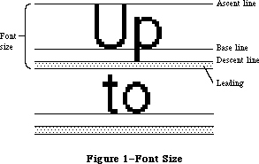 Figure 1–Font Size
Whenever you call a QuickDraw routine that does anything with text, QuickDraw passes the following information to the Font Manager:
• The font number.
• The character style, which is a set of stylistic variations. The
empty set indicates plain text. (See the QuickDraw chapter for details.)
• The font size. The size may range from 1 point to 127 points, but for
readability should be at least 6 points.
• The horizontal and vertical scaling factors, each of which is
represented by a numerator and a denominator (for example, a numerator
of 2 and a denominator of 1 indicates 2-to-1 scaling in that direction).
• A Boolean value indicating whether the characters will actually be drawn
or not. They will not be drawn, for example, when the QuickDraw function
CharWidth is called (since it only measures characters) or when text is
drawn after the pen has been hidden (such as by the HidePen procedure
or the OpenPicture function, which calls HidePen).
• Device specific information that enables the Font Manager to achieve
the best possible results when drawing text on a particular device.
For details, see the section “Communication between QuickDraw and the
Font Manager” below.
Given this information, the Font Manager provides QuickDraw with information describing the font and—if the characters will actually be drawn—the bits comprising the characters.
Fonts are stored as resources in resource files; the Font Manager calls the Resource Manager to read them into memory. System-defined fonts are stored in the system resource file. You may define your own fonts and include them in the system resource file so they can be shared among applications. In special cases, you may want to store a font in an application’s resource file. It’s also possible to store only the character widths and general font information, and not the bits comprising the characters, for those cases where the characters won’t actually be drawn.
A font may be stored in any number of sizes in a resource file. If a size is needed that’s not available as a resource, the Font Manager scales an available size.
Fonts occupy a large amount of storage: A 12-point font typically occupies about 3K bytes, and a 24-point font, about 10K bytes; fonts for use on a high resolution output device can take up four times as much space as that (up to 32K bytes). Fonts are normally purgeable, which means they may be removed from the heap when space is required by the Memory Manager. If you wish, you can call a Font Manager routine to make a font temporarily unpurgeable.
There are also routines that provide information about a font. You can find out the name of a font having a particular font number, or the font number for a font having a particular name. You can also learn whether a font is available in a certain size or will have to be scaled to that size.
Note: The extensions to the Font Manager described in the following paragraphs
were originally documented in Inside Macintosh, Volume IV. As such,
this information refers to the 128K ROMs and System file version 3.2
and later.
The Font Manager has been significantly improved by the addition of new data structures, most notably the family record. Containing additional typographic information about a font, the family record allows more fonts, fractional character widths (that is, character widths expressed as fixed-point numbers rather than simple integers) for greater precision on high-resolution devices such as the LaserWriter, and the option of disabling font scaling for improved speed and legibility.
The addition of the family record and its related data structures is transparent to most existing applications and is of interest only to advanced programmers designing specialized fonts for the LaserWriter or writing their own font editors.
Most programmers will simply want to take advantage of the new features. Two routines, SetFractEnable and SetFScaleDisable, are provided for this purpose; they’re described in “Font Manager Routines” below.
Note: The extensions to the Font Manager described in the following paragraphs
were originally documented in Inside Macintosh, Volume V. As such,
this information refers to the Macintosh SE and Macintosh II ROMs and
System file version 4.1 and later.
The Font Manager has been enhanced in the Macintosh SE and Macintosh II. Multibit pixel description for fonts provides color support on the Macintosh II; this includes the ability to create “gray-scale” fonts—character images with shades of gray (instead of merely black and white).
The SetFractEnable routine has been put into ROM, various bugs have been fixed, and a better font search algorithm has been implemented.
_______________________________________________________________________________
»FONT NUMBERS
_______________________________________________________________________________
Note: The information on Font Numbers described in the following
paragraphs was originally documented in Inside Macintosh, Volume I.
The Font Manager includes the following font numbers for identifying system-defined fonts:
CONST systemFont = 0; {system font}
applFont = 1; {application font}
newYork = 2;
geneva = 3;
monaco = 4;
venice = 5;
london = 6;
athens = 7;
sanFran = 8;
toronto = 9;
cairo = 11;
losAngeles = 12;
times = 20;
helvetica = 21;
courier = 22;
symbol = 23;
taliesin = 24;
The system font is so called because it’s the font used by the system (for drawing menu titles and commands in menus, for example). The name of the system font is Chicago. The size of text drawn by the system in this font is fixed at 12 points (called the system font size).
The application font is the font your application will use unless you specify otherwise. Unlike the system font, the application font isn’t a separate font, but is essentially a reference to another font—Geneva, by default. (The application font number is determined by a value that you can set in parameter RAM; see the Operating System Utilities chapter for more information.)
Assembly-language note: You can get the application font number
from the global variable ApFontID.
_______________________________________________________________________________
»FONTS AND THEIR FAMILIES
_______________________________________________________________________________
Note: The extensions to the Font Manager described in the following section
were originally documented in Inside Macintosh, Volume IV. As such,
this information refers to the 128K ROMs and System file version 3.2
and later.
In the 64K ROM version of the Font Manager, font is defined as the complete set of characters of one typeface; it doesn’t include the size of the characters, and usually doesn’t include any stylistic variations. In other words, fonts are defined in the plain style and stylistic variations, such as bold and italic, are applied to them. For example, Times plain (or roman) defines the font, while Times italic is a stylistic variation applied to that font.
In the 128K ROM version, the definition of a font is broadened to include stylistic variations. That is, a separate font can be defined for certain stylistic variations of a typeface. The set of available fonts for a given typeface is known as a font family.
This allows QuickDraw to use an actual font instead of modifying a plain font, thereby improving speed and readability. For example, suppose the user of a word processor selects a phrase in 12-point Times Roman and chooses the italic style from a menu. QuickDraw asks for an italic Times and, assuming that the proper resources are available, the Font Manager returns a 12-point Times Italic font. QuickDraw could then draw the phrase from an actual italic font rather than having to slant the plain font.
Note: The standard stylistic variations will still be performed by
QuickDraw when they’re not available as actual fonts.
Information about fonts and their families is stored as resources in resource files; the Font Manager calls the Resource Manager to read them into memory. Fonts are stored as resources of type 'FONT' or 'NFNT'. Fonts known to the system are stored in the system resource file; you may also define your own fonts and include them in your application’s resource file. The information about a font family is stored as a resource of type 'FOND'; this includes the resource IDs of all the fonts in the family, as shown in Figure 2.
Figure 1–Font Size
Whenever you call a QuickDraw routine that does anything with text, QuickDraw passes the following information to the Font Manager:
• The font number.
• The character style, which is a set of stylistic variations. The
empty set indicates plain text. (See the QuickDraw chapter for details.)
• The font size. The size may range from 1 point to 127 points, but for
readability should be at least 6 points.
• The horizontal and vertical scaling factors, each of which is
represented by a numerator and a denominator (for example, a numerator
of 2 and a denominator of 1 indicates 2-to-1 scaling in that direction).
• A Boolean value indicating whether the characters will actually be drawn
or not. They will not be drawn, for example, when the QuickDraw function
CharWidth is called (since it only measures characters) or when text is
drawn after the pen has been hidden (such as by the HidePen procedure
or the OpenPicture function, which calls HidePen).
• Device specific information that enables the Font Manager to achieve
the best possible results when drawing text on a particular device.
For details, see the section “Communication between QuickDraw and the
Font Manager” below.
Given this information, the Font Manager provides QuickDraw with information describing the font and—if the characters will actually be drawn—the bits comprising the characters.
Fonts are stored as resources in resource files; the Font Manager calls the Resource Manager to read them into memory. System-defined fonts are stored in the system resource file. You may define your own fonts and include them in the system resource file so they can be shared among applications. In special cases, you may want to store a font in an application’s resource file. It’s also possible to store only the character widths and general font information, and not the bits comprising the characters, for those cases where the characters won’t actually be drawn.
A font may be stored in any number of sizes in a resource file. If a size is needed that’s not available as a resource, the Font Manager scales an available size.
Fonts occupy a large amount of storage: A 12-point font typically occupies about 3K bytes, and a 24-point font, about 10K bytes; fonts for use on a high resolution output device can take up four times as much space as that (up to 32K bytes). Fonts are normally purgeable, which means they may be removed from the heap when space is required by the Memory Manager. If you wish, you can call a Font Manager routine to make a font temporarily unpurgeable.
There are also routines that provide information about a font. You can find out the name of a font having a particular font number, or the font number for a font having a particular name. You can also learn whether a font is available in a certain size or will have to be scaled to that size.
Note: The extensions to the Font Manager described in the following paragraphs
were originally documented in Inside Macintosh, Volume IV. As such,
this information refers to the 128K ROMs and System file version 3.2
and later.
The Font Manager has been significantly improved by the addition of new data structures, most notably the family record. Containing additional typographic information about a font, the family record allows more fonts, fractional character widths (that is, character widths expressed as fixed-point numbers rather than simple integers) for greater precision on high-resolution devices such as the LaserWriter, and the option of disabling font scaling for improved speed and legibility.
The addition of the family record and its related data structures is transparent to most existing applications and is of interest only to advanced programmers designing specialized fonts for the LaserWriter or writing their own font editors.
Most programmers will simply want to take advantage of the new features. Two routines, SetFractEnable and SetFScaleDisable, are provided for this purpose; they’re described in “Font Manager Routines” below.
Note: The extensions to the Font Manager described in the following paragraphs
were originally documented in Inside Macintosh, Volume V. As such,
this information refers to the Macintosh SE and Macintosh II ROMs and
System file version 4.1 and later.
The Font Manager has been enhanced in the Macintosh SE and Macintosh II. Multibit pixel description for fonts provides color support on the Macintosh II; this includes the ability to create “gray-scale” fonts—character images with shades of gray (instead of merely black and white).
The SetFractEnable routine has been put into ROM, various bugs have been fixed, and a better font search algorithm has been implemented.
_______________________________________________________________________________
»FONT NUMBERS
_______________________________________________________________________________
Note: The information on Font Numbers described in the following
paragraphs was originally documented in Inside Macintosh, Volume I.
The Font Manager includes the following font numbers for identifying system-defined fonts:
CONST systemFont = 0; {system font}
applFont = 1; {application font}
newYork = 2;
geneva = 3;
monaco = 4;
venice = 5;
london = 6;
athens = 7;
sanFran = 8;
toronto = 9;
cairo = 11;
losAngeles = 12;
times = 20;
helvetica = 21;
courier = 22;
symbol = 23;
taliesin = 24;
The system font is so called because it’s the font used by the system (for drawing menu titles and commands in menus, for example). The name of the system font is Chicago. The size of text drawn by the system in this font is fixed at 12 points (called the system font size).
The application font is the font your application will use unless you specify otherwise. Unlike the system font, the application font isn’t a separate font, but is essentially a reference to another font—Geneva, by default. (The application font number is determined by a value that you can set in parameter RAM; see the Operating System Utilities chapter for more information.)
Assembly-language note: You can get the application font number
from the global variable ApFontID.
_______________________________________________________________________________
»FONTS AND THEIR FAMILIES
_______________________________________________________________________________
Note: The extensions to the Font Manager described in the following section
were originally documented in Inside Macintosh, Volume IV. As such,
this information refers to the 128K ROMs and System file version 3.2
and later.
In the 64K ROM version of the Font Manager, font is defined as the complete set of characters of one typeface; it doesn’t include the size of the characters, and usually doesn’t include any stylistic variations. In other words, fonts are defined in the plain style and stylistic variations, such as bold and italic, are applied to them. For example, Times plain (or roman) defines the font, while Times italic is a stylistic variation applied to that font.
In the 128K ROM version, the definition of a font is broadened to include stylistic variations. That is, a separate font can be defined for certain stylistic variations of a typeface. The set of available fonts for a given typeface is known as a font family.
This allows QuickDraw to use an actual font instead of modifying a plain font, thereby improving speed and readability. For example, suppose the user of a word processor selects a phrase in 12-point Times Roman and chooses the italic style from a menu. QuickDraw asks for an italic Times and, assuming that the proper resources are available, the Font Manager returns a 12-point Times Italic font. QuickDraw could then draw the phrase from an actual italic font rather than having to slant the plain font.
Note: The standard stylistic variations will still be performed by
QuickDraw when they’re not available as actual fonts.
Information about fonts and their families is stored as resources in resource files; the Font Manager calls the Resource Manager to read them into memory. Fonts are stored as resources of type 'FONT' or 'NFNT'. Fonts known to the system are stored in the system resource file; you may also define your own fonts and include them in your application’s resource file. The information about a font family is stored as a resource of type 'FOND'; this includes the resource IDs of all the fonts in the family, as shown in Figure 2.
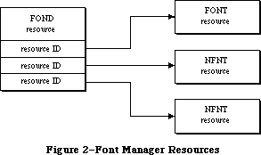 Figure 2–Font Manager Resources
X-Ref: Technical Note #198
The 'NFNT' resource is new to the 128K ROM version of the Font Manager; it has the same format as the 'FONT' resource and allows for many more fonts. An 'NFNT' resource type can also be used to mask all but plain fonts from appearing in a font menu. In this way, the system resource file can contain Times, Times Italic, Times Bold, and Times Bold Italic, yet only Times will appear on the Font Menu. (The user would need to choose Italic from the Style menu.)
The 64K ROM can only handle 'FONT' resources; it ignores resources of type
'NFNT' and 'FOND'.
Warning: If you’re creating a font, be sure to read the section
“Restrictions on the 'FONT' type” below for information
on maintaining compatibility with the 64K ROMs.
It’s crucial that all new fonts have a corresponding 'FOND' resource. A minimal 'FOND' resource can be made for a font by using the Font/DA Mover (version 3.0 or later) to copy the font into a different file that has no font with the same name.
Note: A 'FOND' resource created this way does not contain any optional
tables, but it does contain the font association table (described
below) that maps family numbers and font sizes into resource IDs.
Warning: Be aware that when a 'FOND' is present, the Font Manager uses
it exclusively to determine which fonts are available. Fonts
should be added to or deleted from the System file with a tool
like the Font/DA Mover, which correctly updates the 'FOND' as
well as the 'FONT'.
The Font Manager uses these resources to build two data structures in the application heap. The font record contains information about a font and the family record contains information about a font family.
_______________________________________________________________________________
»About Names and Numbers
In the 64K ROM version of the Font Manager, a font is identified by its font number, which is always between 0 and 255. Each font also has a name that’s used to identify it in menus. Font families are identified by a family number and a family name. Since existing routines rely on passing and returning the font number in Font Manager routines, the family number must be the same as the font number, and the family name must be the same as the font name. Family numbers 0 through 127 are reserved for use by Apple; numbers 128 through 255 are assigned by Apple for fonts created by software developers.
X-Ref: Technical Note #191
X-Ref: Technical Note #245
Assembly-language note: You can determine the system family number and size
by reading the global variables SysFontFam and
SysFontSiz, respectively. This is highly recommended,
especially if your application is intended to run on
Macintoshes that are localized for non-English-
speaking countries, as the localization process may
change the system font.
You can get the family number of the application font
from the global variable ApFontID. You can substitute
a different family number in this variable but the
application font is reset to its default value (it’s
stored in parameter RAM) whenever a new application
is launched.
Since font numbers only range from 0 to 255, only font families with family numbers in this range are recognized by the 64K ROM version of the Font Manager. All fonts with family numbers from 0 through 255 are stored as resources of type 'FONT', so that the 64K ROM’s version of the Font Manager can recognize them.
It’s very important that all new fonts and font families be registered with Apple to avoid conflict. To register the name of a font family, write to:
Font Registration Program
Apple Computer, Inc.
20400 Stevens Creek Blvd., M/S 75-3T
Cupertino, CA 95014
When there’s a conflict, font families may be renumbered by the Font/DA Mover. For instance, when the Font/DA Mover moves a font or font family into a file in which there’s already a font (or font family) with that number (but with a different name), the new font (or font family) is renumbered. For this reason, you should always call GetFNum to verify the number of a font you want to access.
_______________________________________________________________________________
»FONT MANAGER DATA STRUCTURES
_______________________________________________________________________________
Note: The extensions to the Font Manager described in this section were
originally documented in Inside Macintosh, Volumes IV and V. As such,
the Volume IV information refers to the 128K ROM and System file
version 3.2 and later, while the Volume V information refers to the
Macintosh SE and Macintosh II ROMs and System file version 4.1 and
later.
This section describes the data structures that define fonts and font families, including fonts with depth on the Macintosh II; you need to read it only if
you’re going to define your own fonts or write your own font editor. Most of the information in this section is useful only to assembly-language programmers.
Figure 3 shows some of the relationships between the various data structures used by the Font Manager. Handles are shown as dotted lines.
Figure 2–Font Manager Resources
X-Ref: Technical Note #198
The 'NFNT' resource is new to the 128K ROM version of the Font Manager; it has the same format as the 'FONT' resource and allows for many more fonts. An 'NFNT' resource type can also be used to mask all but plain fonts from appearing in a font menu. In this way, the system resource file can contain Times, Times Italic, Times Bold, and Times Bold Italic, yet only Times will appear on the Font Menu. (The user would need to choose Italic from the Style menu.)
The 64K ROM can only handle 'FONT' resources; it ignores resources of type
'NFNT' and 'FOND'.
Warning: If you’re creating a font, be sure to read the section
“Restrictions on the 'FONT' type” below for information
on maintaining compatibility with the 64K ROMs.
It’s crucial that all new fonts have a corresponding 'FOND' resource. A minimal 'FOND' resource can be made for a font by using the Font/DA Mover (version 3.0 or later) to copy the font into a different file that has no font with the same name.
Note: A 'FOND' resource created this way does not contain any optional
tables, but it does contain the font association table (described
below) that maps family numbers and font sizes into resource IDs.
Warning: Be aware that when a 'FOND' is present, the Font Manager uses
it exclusively to determine which fonts are available. Fonts
should be added to or deleted from the System file with a tool
like the Font/DA Mover, which correctly updates the 'FOND' as
well as the 'FONT'.
The Font Manager uses these resources to build two data structures in the application heap. The font record contains information about a font and the family record contains information about a font family.
_______________________________________________________________________________
»About Names and Numbers
In the 64K ROM version of the Font Manager, a font is identified by its font number, which is always between 0 and 255. Each font also has a name that’s used to identify it in menus. Font families are identified by a family number and a family name. Since existing routines rely on passing and returning the font number in Font Manager routines, the family number must be the same as the font number, and the family name must be the same as the font name. Family numbers 0 through 127 are reserved for use by Apple; numbers 128 through 255 are assigned by Apple for fonts created by software developers.
X-Ref: Technical Note #191
X-Ref: Technical Note #245
Assembly-language note: You can determine the system family number and size
by reading the global variables SysFontFam and
SysFontSiz, respectively. This is highly recommended,
especially if your application is intended to run on
Macintoshes that are localized for non-English-
speaking countries, as the localization process may
change the system font.
You can get the family number of the application font
from the global variable ApFontID. You can substitute
a different family number in this variable but the
application font is reset to its default value (it’s
stored in parameter RAM) whenever a new application
is launched.
Since font numbers only range from 0 to 255, only font families with family numbers in this range are recognized by the 64K ROM version of the Font Manager. All fonts with family numbers from 0 through 255 are stored as resources of type 'FONT', so that the 64K ROM’s version of the Font Manager can recognize them.
It’s very important that all new fonts and font families be registered with Apple to avoid conflict. To register the name of a font family, write to:
Font Registration Program
Apple Computer, Inc.
20400 Stevens Creek Blvd., M/S 75-3T
Cupertino, CA 95014
When there’s a conflict, font families may be renumbered by the Font/DA Mover. For instance, when the Font/DA Mover moves a font or font family into a file in which there’s already a font (or font family) with that number (but with a different name), the new font (or font family) is renumbered. For this reason, you should always call GetFNum to verify the number of a font you want to access.
_______________________________________________________________________________
»FONT MANAGER DATA STRUCTURES
_______________________________________________________________________________
Note: The extensions to the Font Manager described in this section were
originally documented in Inside Macintosh, Volumes IV and V. As such,
the Volume IV information refers to the 128K ROM and System file
version 3.2 and later, while the Volume V information refers to the
Macintosh SE and Macintosh II ROMs and System file version 4.1 and
later.
This section describes the data structures that define fonts and font families, including fonts with depth on the Macintosh II; you need to read it only if
you’re going to define your own fonts or write your own font editor. Most of the information in this section is useful only to assembly-language programmers.
Figure 3 shows some of the relationships between the various data structures used by the Font Manager. Handles are shown as dotted lines.
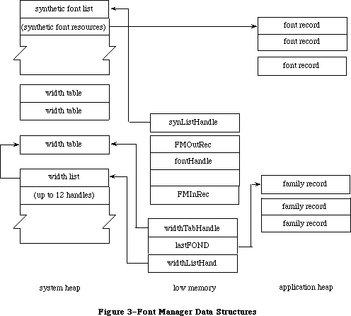 Figure 3–Font Manager Data Structures
Font records and family records, the structures from which global width tables are derived, are kept in the application heap. Global width tables, which are used constantly, are kept in the system heap.
Note: The extensions to the Font Manager described in the following paragraphs
were originally documented in Inside Macintosh, Volume V. As such,
this information refers to the Macintosh SE and Macintosh II ROMs and
System file version 4.1 and later.
Just as the Color QuickDraw pixel image lets you use multiple bits to describe each pixel, the Font Manager lets you create fonts whose character images contain multiple bits per pixel. The number of bits per pixel, or the font depth, is specified in the font record (outlined below); font depths of one, two, four, and eight bits are supported.
Drawing to the screen is considerably faster if the font depth matches the screen depth specified by the user in the Control Panel. For speedy access,
4-bit and 8-bit versions of the system font, as well as a 4-bit Geneva font, are stored in the Macintosh II ROM as 'NFNT' resources.
It’s not necessary, however, to create separate resources matching each of the possible screen depths for every font family. If a resource (either of type
'FONT' or 'NFNT') with a depth corresponding to the current screen depth can’t be found, the Font Manager expands the 1-bit font into a synthetic font matching the current screen depth.
A synthetic font list contains information about each synthetic font; the format of an entry in this list is given in Figure 4. The global variable SynListHandle contains a handle to the synthetic font list.
Figure 3–Font Manager Data Structures
Font records and family records, the structures from which global width tables are derived, are kept in the application heap. Global width tables, which are used constantly, are kept in the system heap.
Note: The extensions to the Font Manager described in the following paragraphs
were originally documented in Inside Macintosh, Volume V. As such,
this information refers to the Macintosh SE and Macintosh II ROMs and
System file version 4.1 and later.
Just as the Color QuickDraw pixel image lets you use multiple bits to describe each pixel, the Font Manager lets you create fonts whose character images contain multiple bits per pixel. The number of bits per pixel, or the font depth, is specified in the font record (outlined below); font depths of one, two, four, and eight bits are supported.
Drawing to the screen is considerably faster if the font depth matches the screen depth specified by the user in the Control Panel. For speedy access,
4-bit and 8-bit versions of the system font, as well as a 4-bit Geneva font, are stored in the Macintosh II ROM as 'NFNT' resources.
It’s not necessary, however, to create separate resources matching each of the possible screen depths for every font family. If a resource (either of type
'FONT' or 'NFNT') with a depth corresponding to the current screen depth can’t be found, the Font Manager expands the 1-bit font into a synthetic font matching the current screen depth.
A synthetic font list contains information about each synthetic font; the format of an entry in this list is given in Figure 4. The global variable SynListHandle contains a handle to the synthetic font list.
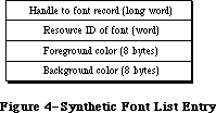 Figure 4–Synthetic Font List Entry
_______________________________________________________________________________
»Format of a Font
Note: The information on the Format of a Font described in the following
paragraphs was originally documented in Inside Macintosh, Volume I.
Each character in a font is defined by bits arranged in rows and columns. This bit arrangement is called a character image; it’s the image inside each of the character rectangles shown in Figure 5.
The base line is a horizontal line coincident with the bottom of each character, excluding descenders.
The character origin is a point on the base line used as a reference location for drawing the character. Conceptually the base line is the line that the pen is on when it starts drawing a character, and the characer origin is the point where the pen starts drawing.
The character rectangle is a rectangle enclosing the character image; its sides are defined by the image width and the font height:
• The image width is simply the width of the character image, which
varies among characters in the font. It may or may not include space
on either side of the character; to minimize the amount of memory
required to store the font, it should not include space.
• The font height is the distance from the ascent line to the descent
line (which is the same for all characters in the font).
The image width is different from the character width, which is the distance to move the pen from this character’s origin to the next character’s origin while drawing. The character width may be 0, in which case the following character will be superimposed on this character (useful for accents, underscores, and so on). Characters whose image width is 0 (such as a space) can have a nonzero character width.
Characters in a proportional font all have character widths proportional to their image width, whereas characters in a fixed-width font all have the same character width.
Characters can kern; that is, they can overlap adjacent characters. The first character in Figure 5 below doesn’t kern, but the second one kerns left.
In addition to the terms used to describe individual characters, there are terms describing features of the font as a whole (see Figure 6).
The font rectangle is related to the character rectangle. Imagine that all the character images in the font are superimposed with their origins coinciding. The smallest rectangle enclosing all the superimposed images is the font rectangle.
The ascent is the distance from the base line to the top of the font rectangle, and the descent is the distance from the base line to the bottom of the font rectangle.
The height of the font rectangle is the font height, which is the same as the height of each character rectangle. The maximum height is 127 pixels. The maximum width of the font rectangle is 254 pixels.
The leading is the amount of blank space to draw between lines of single spaced text—the distance between the descent line of one line of text and the ascent line of the next line of text.
Finally, for each character in a font there’s a character offset. As illustrated in Figure 7, the character offset is simply the difference in position of the character rectangle for a given character and the font rectangle.
Every font has a bit image that contains a complete sequence of all its character images (see Figure 8). The number of rows in the bit image is equivalent to the font height. The character images in the font are stored in the bit image as though the characters were laid out horizontally (in ASCII order, by convention) along a common base line.
The bit image doesn’t have to contain a character image for every character in the font. Instead, any characters marked as being missing from the font are omitted from the bit image. When QuickDraw tries to draw such characters, a missing symbol is drawn instead. The missing symbol is stored in the bit image after all the other character images.
Figure 4–Synthetic Font List Entry
_______________________________________________________________________________
»Format of a Font
Note: The information on the Format of a Font described in the following
paragraphs was originally documented in Inside Macintosh, Volume I.
Each character in a font is defined by bits arranged in rows and columns. This bit arrangement is called a character image; it’s the image inside each of the character rectangles shown in Figure 5.
The base line is a horizontal line coincident with the bottom of each character, excluding descenders.
The character origin is a point on the base line used as a reference location for drawing the character. Conceptually the base line is the line that the pen is on when it starts drawing a character, and the characer origin is the point where the pen starts drawing.
The character rectangle is a rectangle enclosing the character image; its sides are defined by the image width and the font height:
• The image width is simply the width of the character image, which
varies among characters in the font. It may or may not include space
on either side of the character; to minimize the amount of memory
required to store the font, it should not include space.
• The font height is the distance from the ascent line to the descent
line (which is the same for all characters in the font).
The image width is different from the character width, which is the distance to move the pen from this character’s origin to the next character’s origin while drawing. The character width may be 0, in which case the following character will be superimposed on this character (useful for accents, underscores, and so on). Characters whose image width is 0 (such as a space) can have a nonzero character width.
Characters in a proportional font all have character widths proportional to their image width, whereas characters in a fixed-width font all have the same character width.
Characters can kern; that is, they can overlap adjacent characters. The first character in Figure 5 below doesn’t kern, but the second one kerns left.
In addition to the terms used to describe individual characters, there are terms describing features of the font as a whole (see Figure 6).
The font rectangle is related to the character rectangle. Imagine that all the character images in the font are superimposed with their origins coinciding. The smallest rectangle enclosing all the superimposed images is the font rectangle.
The ascent is the distance from the base line to the top of the font rectangle, and the descent is the distance from the base line to the bottom of the font rectangle.
The height of the font rectangle is the font height, which is the same as the height of each character rectangle. The maximum height is 127 pixels. The maximum width of the font rectangle is 254 pixels.
The leading is the amount of blank space to draw between lines of single spaced text—the distance between the descent line of one line of text and the ascent line of the next line of text.
Finally, for each character in a font there’s a character offset. As illustrated in Figure 7, the character offset is simply the difference in position of the character rectangle for a given character and the font rectangle.
Every font has a bit image that contains a complete sequence of all its character images (see Figure 8). The number of rows in the bit image is equivalent to the font height. The character images in the font are stored in the bit image as though the characters were laid out horizontally (in ASCII order, by convention) along a common base line.
The bit image doesn’t have to contain a character image for every character in the font. Instead, any characters marked as being missing from the font are omitted from the bit image. When QuickDraw tries to draw such characters, a missing symbol is drawn instead. The missing symbol is stored in the bit image after all the other character images.
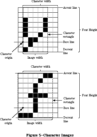 Figure 5–Character Images
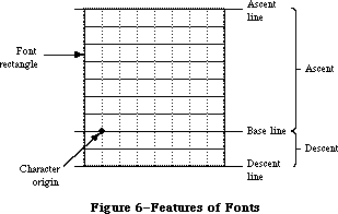 Figure 6–Features of Fonts
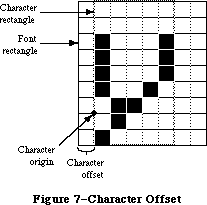 Figure 7–Character Offset
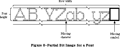 Figure 8–Partial Bit Image for a Font
Warning: Every font must have a missing symbol. The characters with
ASCII codes 0 (NUL), $09 (horizontal tab), and $0D (Return)
must not be missing from the font if there’s any chance it
will ever be used by TextEdit; usually they’ll be zero-length,
but you may want to store a space for the tab character.
_______________________________________________________________________________
»Font Records
The information describing a font is contained in a data structure called a font record, which contains the following:
• the font type (fixed-width or proportional)
• the ASCII code of the first character and the last character in the font
• the maximum character width and maximum amount any character kerns
• the font height, ascent, descent, and leading
• the bit image of the font
• a location table, which is an array of words specifying the location
of each character image within the bit image
• an offset/width table, which is an array of words specifying the
character offset and character width for each character in the font
For every character, the location table contains a word that specifies the bit offset to the location of that character’s image in the bit image. The entry for a character missing from the font contains the same value as the entry for the next character. The last word of the table contains the offset to one bit beyond the end of the bit image (that is, beyond the character image for the missing symbol). The image width of each character is determined from the location table by subtracting the bit offset to that character from the bit offset to the next character in the table.
There’s also one word in the offset/width table for every character: The high-order byte specifies the character offset and the low order byte specifies the character width. Missing characters are flagged in this table by a word value of –1. The last word is also –1, indicating the end of the table.
Note: The 64K ROM version of the Resource Manager limits the total space
occupied by the bit image, location table, offset/width table, and
character-width and image-height tables to 32K bytes. For this reason,
the practical limit on the font size of a full font is about 40 points.
Figure 9 illustrates a sample location table and offset/width table corresponding to the bit image in Figure 8 above.
A font record is referred to by a handle that you can get by calling the FMSwapFont function or the Resource Manager function GetResource. The data type for a font record is as follows:
TYPE FontRec = RECORD
fontType: INTEGER; {font type}
firstChar: INTEGER; {ASCII code of first character}
lastChar: INTEGER; {ASCII code of last character}
widMax: INTEGER; {maximum character width}
kernMax: INTEGER; {negative of maximum character kern}
nDescent: INTEGER; {negative of descent}
fRectWidth: INTEGER; {width of font rectangle}
fRectHeight: INTEGER; {height of font rectangle}
owTLoc: INTEGER; {offset to offset/width table}
ascent: INTEGER; {ascent}
descent: INTEGER; {descent}
leading: INTEGER; {leading}
rowWords: INTEGER; {row width of bit image / 2}
{ bitImage: ARRAY[1..rowWords,1..fRectHeight] OF INTEGER; }
{bit image}
{ locTable: ARRAY[firstChar..lastChar+2] OF INTEGER; }
{location table}
{ owTable: ARRAY[firstChar..lastChar+2] OF INTEGER; }
{offset/width table}
END;
Note: The variable-length arrays appear as comments because they’re
not valid Pascal syntax; they’re used only as conceptual aids.
Figure 8–Partial Bit Image for a Font
Warning: Every font must have a missing symbol. The characters with
ASCII codes 0 (NUL), $09 (horizontal tab), and $0D (Return)
must not be missing from the font if there’s any chance it
will ever be used by TextEdit; usually they’ll be zero-length,
but you may want to store a space for the tab character.
_______________________________________________________________________________
»Font Records
The information describing a font is contained in a data structure called a font record, which contains the following:
• the font type (fixed-width or proportional)
• the ASCII code of the first character and the last character in the font
• the maximum character width and maximum amount any character kerns
• the font height, ascent, descent, and leading
• the bit image of the font
• a location table, which is an array of words specifying the location
of each character image within the bit image
• an offset/width table, which is an array of words specifying the
character offset and character width for each character in the font
For every character, the location table contains a word that specifies the bit offset to the location of that character’s image in the bit image. The entry for a character missing from the font contains the same value as the entry for the next character. The last word of the table contains the offset to one bit beyond the end of the bit image (that is, beyond the character image for the missing symbol). The image width of each character is determined from the location table by subtracting the bit offset to that character from the bit offset to the next character in the table.
There’s also one word in the offset/width table for every character: The high-order byte specifies the character offset and the low order byte specifies the character width. Missing characters are flagged in this table by a word value of –1. The last word is also –1, indicating the end of the table.
Note: The 64K ROM version of the Resource Manager limits the total space
occupied by the bit image, location table, offset/width table, and
character-width and image-height tables to 32K bytes. For this reason,
the practical limit on the font size of a full font is about 40 points.
Figure 9 illustrates a sample location table and offset/width table corresponding to the bit image in Figure 8 above.
A font record is referred to by a handle that you can get by calling the FMSwapFont function or the Resource Manager function GetResource. The data type for a font record is as follows:
TYPE FontRec = RECORD
fontType: INTEGER; {font type}
firstChar: INTEGER; {ASCII code of first character}
lastChar: INTEGER; {ASCII code of last character}
widMax: INTEGER; {maximum character width}
kernMax: INTEGER; {negative of maximum character kern}
nDescent: INTEGER; {negative of descent}
fRectWidth: INTEGER; {width of font rectangle}
fRectHeight: INTEGER; {height of font rectangle}
owTLoc: INTEGER; {offset to offset/width table}
ascent: INTEGER; {ascent}
descent: INTEGER; {descent}
leading: INTEGER; {leading}
rowWords: INTEGER; {row width of bit image / 2}
{ bitImage: ARRAY[1..rowWords,1..fRectHeight] OF INTEGER; }
{bit image}
{ locTable: ARRAY[firstChar..lastChar+2] OF INTEGER; }
{location table}
{ owTable: ARRAY[firstChar..lastChar+2] OF INTEGER; }
{offset/width table}
END;
Note: The variable-length arrays appear as comments because they’re
not valid Pascal syntax; they’re used only as conceptual aids.
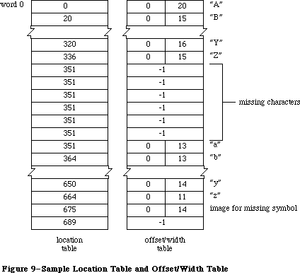 Figure 9–Sample Location Table and Offset/Width Table
The fontType field must contain one of the following predefined constants:
CONST propFont = $9000; {proportional font}
fixedFont = $B000; {fixed-width font}
The values in the widMax, kernMax, nDescent, fRectWidth, fRectHeight, ascent, descent, and leading fields all specify a number of pixels.
KernMax indicates the largest number of pixels any character kerns, that is, the distance from the character origin to the left edge of the font rectangle. It should always be 0 or negative, since the kerned pixels are to the left of the character origin. NDescent is the negative of the descent (the distance from the character origin to the bottom of the font rectangle).
The owTLoc field contains a word offset from itself to the offset/width table; it’s equivalent to
4 + (rowWords * fRectHeight) + (lastChar–firstChar+3) + 1
Warning: Remember, the offset and row width in a font record are
given in words, not bytes.
Assembly-language note: The global variable ROMFont0 contains a handle
to the font record for the system font.
Every size of a font is stored as a separate resource. The resource type for a font is 'FONT'. The resource data for a font is simply a font record:
Number of bytes Contents
2 bytes FontType field of font record
2 bytes FirstChar field of font record
2 bytes LastChar field of font record
2 bytes WidMax field of font record
2 bytes KernMax field of font record
2 bytes NDescent field of font record
2 bytes FRectWidth field of font record
2 bytes FRectHeight field of font record
2 bytes OWTLoc field of font record
2 bytes Ascent field of font record
2 bytes Descent field of font record
2 bytes Leading field of font record
2 bytes RowWords field of font record
n bytes Bit image of font
n = 2 * rowWords * fRectHeight
m bytes Location table of font
m = 2 * (lastChar–firstChar+3)
m bytes Offset/width table of font
m = 2 * (lastChar–firstChar+3)
As shown in Figure 10, the resource ID of a font has the following format: Bits 0-6 are the font size, bits 7-14 are the font number, and bit 15 is 0. Thus the resource ID corresponding to a given font number and size is
(128 * font number) + font size
X-Ref: Technical Note #245
Since 0 is not a valid font size, the resource ID having 0 in the size field is used to provide only the name of the font: The name of the resource is the font name. For example, for a font named Griffin and numbered 200, the resource naming the font would have a resource ID of 25600 and the resource name
'Griffin'. Size 10 of that font would be stored in a resource numbered 25610.
Figure 9–Sample Location Table and Offset/Width Table
The fontType field must contain one of the following predefined constants:
CONST propFont = $9000; {proportional font}
fixedFont = $B000; {fixed-width font}
The values in the widMax, kernMax, nDescent, fRectWidth, fRectHeight, ascent, descent, and leading fields all specify a number of pixels.
KernMax indicates the largest number of pixels any character kerns, that is, the distance from the character origin to the left edge of the font rectangle. It should always be 0 or negative, since the kerned pixels are to the left of the character origin. NDescent is the negative of the descent (the distance from the character origin to the bottom of the font rectangle).
The owTLoc field contains a word offset from itself to the offset/width table; it’s equivalent to
4 + (rowWords * fRectHeight) + (lastChar–firstChar+3) + 1
Warning: Remember, the offset and row width in a font record are
given in words, not bytes.
Assembly-language note: The global variable ROMFont0 contains a handle
to the font record for the system font.
Every size of a font is stored as a separate resource. The resource type for a font is 'FONT'. The resource data for a font is simply a font record:
Number of bytes Contents
2 bytes FontType field of font record
2 bytes FirstChar field of font record
2 bytes LastChar field of font record
2 bytes WidMax field of font record
2 bytes KernMax field of font record
2 bytes NDescent field of font record
2 bytes FRectWidth field of font record
2 bytes FRectHeight field of font record
2 bytes OWTLoc field of font record
2 bytes Ascent field of font record
2 bytes Descent field of font record
2 bytes Leading field of font record
2 bytes RowWords field of font record
n bytes Bit image of font
n = 2 * rowWords * fRectHeight
m bytes Location table of font
m = 2 * (lastChar–firstChar+3)
m bytes Offset/width table of font
m = 2 * (lastChar–firstChar+3)
As shown in Figure 10, the resource ID of a font has the following format: Bits 0-6 are the font size, bits 7-14 are the font number, and bit 15 is 0. Thus the resource ID corresponding to a given font number and size is
(128 * font number) + font size
X-Ref: Technical Note #245
Since 0 is not a valid font size, the resource ID having 0 in the size field is used to provide only the name of the font: The name of the resource is the font name. For example, for a font named Griffin and numbered 200, the resource naming the font would have a resource ID of 25600 and the resource name
'Griffin'. Size 10 of that font would be stored in a resource numbered 25610.
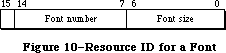 Figure 10–Resource ID for a Font
The resource type 'FRSV' is reserved by the Font Manager; it identifies fonts used by the system. Fonts whose resource IDs are contained in a 'FRSV' resource 1 will not be removed from the system resource file by the Font/DA Mover. The format of a 'FRSV' resource is as follows:
Number of bytes Contents
2 bytes Number of font resource IDs
n * 2 bytes n font resource IDs
»Font Widths
A resource type can be defined that consists of only the character widths and general font information—everything but the font’s bit image and location table. If this 'FWID' resource type exists, it will be read in whenever QuickDraw doesn’t need to draw the text, such as when you call one of the routines CharWidth, HidePen, or OpenPicture (which calls HidePen). The FontRec data type described above, minus the rowWords, bitImage, and locTable fields, reflects the structure of the 'FWID' resource type. The owTLoc field will contain 4, and the fontType field will contain the following predefined constant:
CONST fontWid = $ACB0; {font width data}
Note: The extensions to the Font Manager described in the following paragraphs
were originally documented in Inside Macintosh, Volume IV. As such,
this information refers to the 128K ROMs and System file version 3.2
and later.
To maintain compatibility with existing applications, the order of the fields in the font record remains unchanged; two variable-length arrays are added at the end of the record, however, to implement fractional character widths.
Number of bytes Contents
m bytes Optional character-width table of font
m = 2 * (lastChar–firstChar+3)
m bytes Optional image-height table of font
m = 2 * (lastChar–firstChar+3)
The various sizes of a font are each stored as separate resources. The resource type for a font is either 'FONT' or 'NFNT', which is simply the original font record with the two additional variable-length arrays added at the end of the record.
Additional constants have been defined for use in the fontType field; it can now contain any of the following values:
CONST propFont = $9000; {proportional font}
prpFntH = $9001; { with height table}
prpFntW = $9002; { with width table}
prpFntHW = $9003; { with height & width tables}
fixedFont = $B000; {fixed-width font}
fxdFntH = $B001; { with height table}
fxdFntW = $B002; { with width table}
fxdFntHW = $B003; { with height & width tables}
fontWid = $ACB0; {font width data: 64K ROM only}
The low-order two bits of the fontType field tell whether the two optional tables are present. If bit 0 is set, there’s an image-height table; if bit 1 is set, there’s a character width table.
The optional character-width table immediately follows the offset/width table; it’s a variable-length array specifying the fixed-point character widths for each character in the font. Each entry is a word in length. For compactness, a special 16-bit fixed-point format is used with an unsigned integer part in the high-order byte and a fractional part in the low-order byte.
X-Ref: Technical Note #30
The optional image-height table, which speeds the drawing of characters, may also be appended after the character-width table; it’s a variable-length array specifying the image height of each character in the font. Each entry is a word in length; the high-order byte is the offset of the first non-white row in the character; the low-order byte is the number of rows that must be drawn. The image height is the height of the character image and is less than or equal to the font height; it’s used in conjunction with QuickDraw for improved character plotting. Most font resources don’t contain this table; it’s typically generated by the Font Manager when the font is swapped in.
Note: The 64K ROM version of the Resource Manager limits the total space
occupied by the bit image, location table, offset/width table, and
character-width and image-height tables to 32K bytes. For this reason,
the practical limit on the font size of a full font is about 40 points.
Note: The extensions to the Font Manager described in the following paragraphs
were originally documented in Inside Macintosh, Volume V. As such,
this information refers to the Macintosh SE and Macintosh II ROMs and
System file version 4.1 and later.
Several previously unused bits of the fontType field specify the font depth and other related information (the new bits are marked by an asterisk):
Bit Meaning
0 Set if there’s an image-height table
1 Set if there’s a character-width table
* 2–3 Font depth (Macintosh II only—must be 0 otherwise)
4–6 Reserved (should be 0)
* 7 Set if font has an 'fctb' resource (Macintosh II
only—must be 0 otherwise)
* 8 Set if a synthetic font (Macintosh II only—must be 0 otherwise)
* 9 Set if font contains colors other than black (Macintosh II
only—must be 0 otherwise)
10–11 Reserved (should be 0)
12 Reserved (should be 1)
13 Set for fixed-width font, clear for proportional font
* 14 Set if font is not to be expanded (Macintosh II
only—must be 0 otherwise)
15 Reserved (should be 1)
Bit 2 and 3 specify the font depth and can contain the following values:
Value Font depth
0 1-bit
1 2-bit
2 4-bit
3 8-bit
The font depth is normally 0, indicating a font intended for a screen one bit deep. If bit 7 is set (and the font is an 'NFNT' resource), a resource of type 'fctb' with the same ID as the font can optionally be provided to assign RGB colors to specific pixel values.
Bit 8 is used only by the Font Manager to indicate a synthetic font, created dynamically from the available font resources in response to a certain color and screen depth combination.
Bit 9 is set if the font contains other than black.
Setting bit 14 indicates that the font should not be expanded by the Font Manager to match the screen depth; some international fonts, such as kanji, are too large for synthetic fonts to be effective or meaningful.
To accommodate multibit font depths, the owTLoc field has been changed to a long word, the nDescent field becoming the high-order word. (For backward compatibility, nDescent is ignored if it’s negative.)
Note: The 128K ROM version of the Font Manager limits the strike for a
1-bit font to not quite 128K; this limits the largest practical
font to about 127 points. The Macintosh II ROM limits the largest
practical font to about 255 points, regardless of the font depth.
_______________________________________________________________________________
»Family Records
Note: The extensions to the Font Manager described in the following paragraphs
were originally documented in Inside Macintosh, Volume IV. As such,
this information refers to the 128K ROMs and System file version 3.2
and later.
Assembly-language note: The global variable LastFOND is a handle to the last
family record used. You can read the contents of the
family record by using this handle. You should not
alter the contents of this record.
The data type for a family record is as follows:
TYPE FamRec = RECORD
ffFlags: INTEGER; {flags for family}
ffFamID: INTEGER; {family ID number}
ffFirstChar: INTEGER; {ASCII code of the first character}
ffLastChar: INTEGER; {ASCII code of the last character}
ffAscent: INTEGER; {maximum ascent for 1-pt.font}
ffDescent: INTEGER; {maximum descent for 1-pt.font}
ffLeading: INTEGER; {maximum leading for 1-pt.font}
ffWidMax: INTEGER; {maximum width for 1-pt.font}
ffWTabOff: LONGINT; {offset to width table}
ffKernOff: LONGINT; {offset to kerning table}
ffStylOff: LONGINT; {offset to style-mapping table}
ffProperty: ARRAY[1..9] OF INTEGER; {style property info}
ffIntl: ARRAY[1..2] OF INTEGER; {reserved}
ffVersion: INTEGER; {version number}
{ ffAssoc: FontAssoc;} {font association table}
{ ffWidthTab: WidTable;} {width table}
{ ffStyTab: StyleTable;}{style-mapping table}
{ ffKernTab: KernTable;} {kerning table}
END;
Note: The variable-length arrays appear as comments because they’re not
valid Pascal syntax; they’re used only as conceptual aids. This
version of the FamRec is accurate for Volume IV; the extensions to
the FamRec made in Volume V are not included here.
The ffFlags field defines general characteristics of the font family, as follows:
Bit Meaning
0 Set if there’s an image-height table
1 Set if there’s a character-width table
2–11 Reserved (should be zero)
12 Set to ignore FractEnable when deciding whether to use
fixed-point values for stylistic variations (see bit 13),
clear to treat FractEnable as usual
13 Set to use integer extra width for stylistic variations,
clear to compute fixed-point extra width from the family
style-mapping table when FractEnable is TRUE
14 Set if family fractional-width table is not used, clear
if table is used
15 Set for fixed-width font, clear for proportional font
The values in the ffAscent, ffDescent, ffLeading, and ffWidMax describe the maximum dimensions of the family as they would be for a hypothetical one-point font to be scaled up. They use a special 16-bit fixed-point format with an integer part in the high-order 4 bits and a fractional part in the low-order 12 bits. The FontMetrics procedure calculates the true values by multiplying this number by the actual point size.
The ffWTabOff, ffKernOff, and ffStylOff fields are offsets from the top of the record to the start of the width table, kerning table, and style-mapping table, respectively; if any of these fields is zero, the corresponding table does not exist.
The ffProperty field is the family style-property table, shown in Figure 11.
Figure 10–Resource ID for a Font
The resource type 'FRSV' is reserved by the Font Manager; it identifies fonts used by the system. Fonts whose resource IDs are contained in a 'FRSV' resource 1 will not be removed from the system resource file by the Font/DA Mover. The format of a 'FRSV' resource is as follows:
Number of bytes Contents
2 bytes Number of font resource IDs
n * 2 bytes n font resource IDs
»Font Widths
A resource type can be defined that consists of only the character widths and general font information—everything but the font’s bit image and location table. If this 'FWID' resource type exists, it will be read in whenever QuickDraw doesn’t need to draw the text, such as when you call one of the routines CharWidth, HidePen, or OpenPicture (which calls HidePen). The FontRec data type described above, minus the rowWords, bitImage, and locTable fields, reflects the structure of the 'FWID' resource type. The owTLoc field will contain 4, and the fontType field will contain the following predefined constant:
CONST fontWid = $ACB0; {font width data}
Note: The extensions to the Font Manager described in the following paragraphs
were originally documented in Inside Macintosh, Volume IV. As such,
this information refers to the 128K ROMs and System file version 3.2
and later.
To maintain compatibility with existing applications, the order of the fields in the font record remains unchanged; two variable-length arrays are added at the end of the record, however, to implement fractional character widths.
Number of bytes Contents
m bytes Optional character-width table of font
m = 2 * (lastChar–firstChar+3)
m bytes Optional image-height table of font
m = 2 * (lastChar–firstChar+3)
The various sizes of a font are each stored as separate resources. The resource type for a font is either 'FONT' or 'NFNT', which is simply the original font record with the two additional variable-length arrays added at the end of the record.
Additional constants have been defined for use in the fontType field; it can now contain any of the following values:
CONST propFont = $9000; {proportional font}
prpFntH = $9001; { with height table}
prpFntW = $9002; { with width table}
prpFntHW = $9003; { with height & width tables}
fixedFont = $B000; {fixed-width font}
fxdFntH = $B001; { with height table}
fxdFntW = $B002; { with width table}
fxdFntHW = $B003; { with height & width tables}
fontWid = $ACB0; {font width data: 64K ROM only}
The low-order two bits of the fontType field tell whether the two optional tables are present. If bit 0 is set, there’s an image-height table; if bit 1 is set, there’s a character width table.
The optional character-width table immediately follows the offset/width table; it’s a variable-length array specifying the fixed-point character widths for each character in the font. Each entry is a word in length. For compactness, a special 16-bit fixed-point format is used with an unsigned integer part in the high-order byte and a fractional part in the low-order byte.
X-Ref: Technical Note #30
The optional image-height table, which speeds the drawing of characters, may also be appended after the character-width table; it’s a variable-length array specifying the image height of each character in the font. Each entry is a word in length; the high-order byte is the offset of the first non-white row in the character; the low-order byte is the number of rows that must be drawn. The image height is the height of the character image and is less than or equal to the font height; it’s used in conjunction with QuickDraw for improved character plotting. Most font resources don’t contain this table; it’s typically generated by the Font Manager when the font is swapped in.
Note: The 64K ROM version of the Resource Manager limits the total space
occupied by the bit image, location table, offset/width table, and
character-width and image-height tables to 32K bytes. For this reason,
the practical limit on the font size of a full font is about 40 points.
Note: The extensions to the Font Manager described in the following paragraphs
were originally documented in Inside Macintosh, Volume V. As such,
this information refers to the Macintosh SE and Macintosh II ROMs and
System file version 4.1 and later.
Several previously unused bits of the fontType field specify the font depth and other related information (the new bits are marked by an asterisk):
Bit Meaning
0 Set if there’s an image-height table
1 Set if there’s a character-width table
* 2–3 Font depth (Macintosh II only—must be 0 otherwise)
4–6 Reserved (should be 0)
* 7 Set if font has an 'fctb' resource (Macintosh II
only—must be 0 otherwise)
* 8 Set if a synthetic font (Macintosh II only—must be 0 otherwise)
* 9 Set if font contains colors other than black (Macintosh II
only—must be 0 otherwise)
10–11 Reserved (should be 0)
12 Reserved (should be 1)
13 Set for fixed-width font, clear for proportional font
* 14 Set if font is not to be expanded (Macintosh II
only—must be 0 otherwise)
15 Reserved (should be 1)
Bit 2 and 3 specify the font depth and can contain the following values:
Value Font depth
0 1-bit
1 2-bit
2 4-bit
3 8-bit
The font depth is normally 0, indicating a font intended for a screen one bit deep. If bit 7 is set (and the font is an 'NFNT' resource), a resource of type 'fctb' with the same ID as the font can optionally be provided to assign RGB colors to specific pixel values.
Bit 8 is used only by the Font Manager to indicate a synthetic font, created dynamically from the available font resources in response to a certain color and screen depth combination.
Bit 9 is set if the font contains other than black.
Setting bit 14 indicates that the font should not be expanded by the Font Manager to match the screen depth; some international fonts, such as kanji, are too large for synthetic fonts to be effective or meaningful.
To accommodate multibit font depths, the owTLoc field has been changed to a long word, the nDescent field becoming the high-order word. (For backward compatibility, nDescent is ignored if it’s negative.)
Note: The 128K ROM version of the Font Manager limits the strike for a
1-bit font to not quite 128K; this limits the largest practical
font to about 127 points. The Macintosh II ROM limits the largest
practical font to about 255 points, regardless of the font depth.
_______________________________________________________________________________
»Family Records
Note: The extensions to the Font Manager described in the following paragraphs
were originally documented in Inside Macintosh, Volume IV. As such,
this information refers to the 128K ROMs and System file version 3.2
and later.
Assembly-language note: The global variable LastFOND is a handle to the last
family record used. You can read the contents of the
family record by using this handle. You should not
alter the contents of this record.
The data type for a family record is as follows:
TYPE FamRec = RECORD
ffFlags: INTEGER; {flags for family}
ffFamID: INTEGER; {family ID number}
ffFirstChar: INTEGER; {ASCII code of the first character}
ffLastChar: INTEGER; {ASCII code of the last character}
ffAscent: INTEGER; {maximum ascent for 1-pt.font}
ffDescent: INTEGER; {maximum descent for 1-pt.font}
ffLeading: INTEGER; {maximum leading for 1-pt.font}
ffWidMax: INTEGER; {maximum width for 1-pt.font}
ffWTabOff: LONGINT; {offset to width table}
ffKernOff: LONGINT; {offset to kerning table}
ffStylOff: LONGINT; {offset to style-mapping table}
ffProperty: ARRAY[1..9] OF INTEGER; {style property info}
ffIntl: ARRAY[1..2] OF INTEGER; {reserved}
ffVersion: INTEGER; {version number}
{ ffAssoc: FontAssoc;} {font association table}
{ ffWidthTab: WidTable;} {width table}
{ ffStyTab: StyleTable;}{style-mapping table}
{ ffKernTab: KernTable;} {kerning table}
END;
Note: The variable-length arrays appear as comments because they’re not
valid Pascal syntax; they’re used only as conceptual aids. This
version of the FamRec is accurate for Volume IV; the extensions to
the FamRec made in Volume V are not included here.
The ffFlags field defines general characteristics of the font family, as follows:
Bit Meaning
0 Set if there’s an image-height table
1 Set if there’s a character-width table
2–11 Reserved (should be zero)
12 Set to ignore FractEnable when deciding whether to use
fixed-point values for stylistic variations (see bit 13),
clear to treat FractEnable as usual
13 Set to use integer extra width for stylistic variations,
clear to compute fixed-point extra width from the family
style-mapping table when FractEnable is TRUE
14 Set if family fractional-width table is not used, clear
if table is used
15 Set for fixed-width font, clear for proportional font
The values in the ffAscent, ffDescent, ffLeading, and ffWidMax describe the maximum dimensions of the family as they would be for a hypothetical one-point font to be scaled up. They use a special 16-bit fixed-point format with an integer part in the high-order 4 bits and a fractional part in the low-order 12 bits. The FontMetrics procedure calculates the true values by multiplying this number by the actual point size.
The ffWTabOff, ffKernOff, and ffStylOff fields are offsets from the top of the record to the start of the width table, kerning table, and style-mapping table, respectively; if any of these fields is zero, the corresponding table does not exist.
The ffProperty field is the family style-property table, shown in Figure 11.
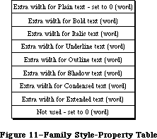 Figure 11–Family Style-Property Table
Each entry is a 16-bit fixed-point number with a signed integer part in the high-order 4 bits and a fractional part in the low-order 12 bits. These numbers are used to calculate the amount of extra width for special stylistic variations; each of these values is multiplied by the point size of the font actually being used. If the font already exists for a given style, the value in its field is ignored.
The ffAssoc field contains the font association table. This table, shown in Figure 12, is used to match a given font size and style combination with the resource ID of an actual font.
Figure 11–Family Style-Property Table
Each entry is a 16-bit fixed-point number with a signed integer part in the high-order 4 bits and a fractional part in the low-order 12 bits. These numbers are used to calculate the amount of extra width for special stylistic variations; each of these values is multiplied by the point size of the font actually being used. If the font already exists for a given style, the value in its field is ignored.
The ffAssoc field contains the font association table. This table, shown in Figure 12, is used to match a given font size and style combination with the resource ID of an actual font.
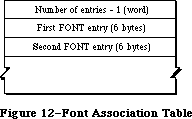 Figure 12–Font Association Table
Note: In order to reduce search time, the Font Manager requires that
the entries be sorted according to the fontSize field, with the
smallest sizes first. If multiple fonts from the same family, the
plain (roman) fonts come first. The Font Manager is optimized to
look first for 'NFNT' resources, then 'FONT' resources.
Each entry in the font association table has the format shown in Figure 13.
Figure 12–Font Association Table
Note: In order to reduce search time, the Font Manager requires that
the entries be sorted according to the fontSize field, with the
smallest sizes first. If multiple fonts from the same family, the
plain (roman) fonts come first. The Font Manager is optimized to
look first for 'NFNT' resources, then 'FONT' resources.
Each entry in the font association table has the format shown in Figure 13.
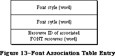 Figure 13–Font Association Table Entry
The font association table is followed by the family character-width table. As shown in Figure 14, this table is actually a number of width tables (since a font family may include numerous styles).
Figure 13–Font Association Table Entry
The font association table is followed by the family character-width table. As shown in Figure 14, this table is actually a number of width tables (since a font family may include numerous styles).
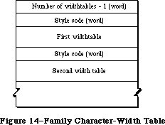 Figure 14–Family Character-Width Table
Each character-width table is preceded by a style code; the low-order byte of this word specifies stylistic variations (see Figure 15). The widths in each table are for a hypothetical one-point font; the actual values for the characters are calculated by multiplying these widths by the font size. The widths in this table are stored in a 16-bit fixed-point format with an unsigned integer part in the high-order 4 bits and a fractional part in the low-order 12 bits.
Figure 14–Family Character-Width Table
Each character-width table is preceded by a style code; the low-order byte of this word specifies stylistic variations (see Figure 15). The widths in each table are for a hypothetical one-point font; the actual values for the characters are calculated by multiplying these widths by the font size. The widths in this table are stored in a 16-bit fixed-point format with an unsigned integer part in the high-order 4 bits and a fractional part in the low-order 12 bits.
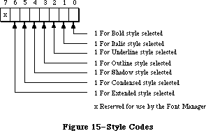 Figure 15–Style Codes
The style-mapping table and its associated tables are used by the LaserWriter driver and are described in the Apple LaserWriter Reference.
The kerning table, like the family character-width table, is actually a number of kerning tables (see Figure 16).
Figure 15–Style Codes
The style-mapping table and its associated tables are used by the LaserWriter driver and are described in the Apple LaserWriter Reference.
The kerning table, like the family character-width table, is actually a number of kerning tables (see Figure 16).
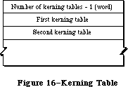 Figure 16–Kerning Table
Each kerning table is preceded by a style code; stored in the low-order byte of the word, this style information has the same format shown in Figure 15 above. The number of entries in the table follows the style word (see Figure 17).
Figure 16–Kerning Table
Each kerning table is preceded by a style code; stored in the low-order byte of the word, this style information has the same format shown in Figure 15 above. The number of entries in the table follows the style word (see Figure 17).
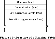 Figure 17–Structure of a Kerning Table
The entries in each kerning table (shown in Figure 18) consist of a pair of characters followed by a kerning offset for a hypothetical one-point font. This value, represented by an integer part in the high-order 4 bits and a fractional part in the low-order 12 bits, is multiplied by the size of the font to obtain the actual offset.
Figure 17–Structure of a Kerning Table
The entries in each kerning table (shown in Figure 18) consist of a pair of characters followed by a kerning offset for a hypothetical one-point font. This value, represented by an integer part in the high-order 4 bits and a fractional part in the low-order 12 bits, is multiplied by the size of the font to obtain the actual offset.
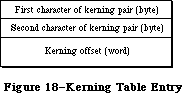 Figure 18–Kerning Table Entry
Note: The extensions to the Font Manager described in the following paragraphs
were originally documented in Inside Macintosh, Volume V. As such,
this information refers to the Macintosh SE and Macintosh II ROMs and
System file version 4.1 and later.
For Macintosh II only, bits 8 and 9 of the font style word within each font association table specify the font depth; they must contain the same value as bits 2 and 3 of the fontType field of the font record. All other undefined bits remain 0.
A font family is stored as a resource of type 'FOND', and with the Macintosh II, it’s format has been extended. The new format is the following (with extension fields indicated by asterisks):
Number of bytes Contents
2 bytes FONDFlags field of family record
2 bytes FONDFamID field of family record
2 bytes FONDFirst field of family record
2 bytes FONDLast field of family record
2 bytes FONDAscent field of family record
2 bytes FONDDescent field of family record
2 bytes FONDLeading field of family record
2 bytes FONDWidMax field of family record
4 bytes FONDWTabOff of family record
4 bytes FONDKernOff of family record
4 bytes FONDStylOff of family record
24 bytes FONDProperty field of family record
4 bytes FONDIntl field of family record
2 bytes *Version number ($02)
m bytes FONDAssoc field of family record (variable length)
2 bytes *Number of offsets minus 1
4 bytes *Offset to bounding box table
n bytes *Bounding box table
p bytes FONDWidTable field of family record (variable length)
q bytes FONDStylTab field of family record (variable length)
r bytes FONDKerntab field of family record (variable length)
The bounding box table has an entry for each style available in the family. The table as a whole has this form:
Number of bytes Contents
2 bytes Number of entries minus 1
10 bytes First entry
10 bytes Second entry . . .
Each bounding box entry has this form, giving the bounding box position with respect to the origin of the characters:
Number of bytes Contents
2 bytes Style word
2 bytes Lower left x coordinate
2 bytes Lower left y coordinate
2 bytes Upper right x coordinate
2 bytes Upper right y coordinate
Note: The extensions to the Font Manager described in the following paragraphs
were originally documented in Inside Macintosh, Volume IV. As such,
this information refers to the 128K ROMs and System file version 3.2
and later.
»Restrictions on the 'FONT' Type
For backward compatibility, all 'FONT' resources that are part of a 'FOND' have certain restrictions:
1. The font name and family name must be identical.
2. The font number and family number must be identical since the
Font Manager interprets a family number as a font number.
3. The resource ID of the font must be the same number that would
be produced by concatenating the font number and the font size.
These restrictions ensure that both the 64K ROM and 128K ROM versions of the Font Manager will associate the family number and point size with the proper corresponding font resource ID, whether or not there’s a family resource. 'NFNT' resources are not bound by these restrictions (but neither will they be found by the 64K ROM version of the Font Manager).
_______________________________________________________________________________
»Global Width Tables
Note: The extensions to the Font Manager described in the following paragraphs
were originally documented in Inside Macintosh, Volume IV. As such,
this information refers to the 128K ROMs and System file version 3.2
and later.
The Font Manager communicates fractional character widths to QuickDraw via a global width table, a data structure allocated in the system heap. A handle to the global width table is returned by the FontMetrics procedure. The format of the global width table is follows:
TYPE WidthTable = RECORD
tabData: ARRAY[1..256] OF Fixed; { character widths}
tabFont: Handle; {font record used to build table}
sExtra: LONGINT; {space extra used for table}
style: LONGINT; {extra due to style}
fID: INTEGER; {font family ID}
fSize: INTEGER; {font size request}
face: INTEGER; {style (face) request}
device: INTEGER; {device requested}
inNumer: Point; {numerators of scaling factors}
inDenom: Point; {denominators of scaling factors}
aFID: INTEGER; {actual font family ID for table}
fHand: handle; {family record used to build table}
usedFam: BOOLEAN; {used fixed-point family widths}
aFace: Byte; {actual face produced}
vOutput: INTEGER; {vertical factor for expanding }
{ characters}
hOutput: INTEGER; {horizontal factor for expanding }
{ characters}
vFactor: INTEGER; {not used}
hFactor: INTEGER; {horizontal factor for increasing }
{ character widths}
aSize: INTEGER; {actual size of actual font used}
tabSize: INTEGER {total size of table}
END;
TabData is an array containing a character width for each of the 255 possible characters in a font, plus one long word for the font’s missing symbol. The widths are stored in the standard 32-bit fixed-point format. If a character is missing, its entry contains the width of the missing symbol. (For efficiency, the Font Manager will store up to 12 recently used global width tables.) InNumer and inDenom contain the vertical and horizontal scaling factors copied from the font input record.
Scaling is effected in two ways: by expanding characters of the chosen font and by artificially increasing the widths of the chosen font in the width table. HOutput and vOutput give the factors by which characters are to be expanded horizontally and vertically. HFactor is the factor by which the widths of the chosen font, after stylistic variations, have been increased. (VFactor is not used.) Thus, multiplying hOutput and vOutput by hFactor and vFactor gives the true font scaling; the product of hOutput and an entry in the width table is that character’s true scaled width. HOutput,vOutput, hFactor, and vFactor are all 16-bit fixed-point numbers, with an integer part in the high-order byte and a fractional part in the low-order byte.
If font scaling has been enabled, hFactor and vFactor both have a value of 1. In any case, hOutput, vOutput, hFactor, and vFactor are adjusted so that the values of hFactor and vFactor lie between 1 and 2, including 1.
Assembly-language note: A handle to the global width table is contained
in the global variable WidthTabHandle. A pointer
to the table is contained in the global variable
WidthPtr; it’s reliable immediately after a call
to FMSwapFont but, like all pointers, may become
invalid after a call to the Memory Manager.
The global variable WidthListHand is a handle to a
list of handles to up to 12 recently-used width
tables. You can scan this list, looking for width
tables that match the family number, size, and style
of the font you wish to measure. If you reach a width
handle that’s equal to –1, that width table is
invalid, and you must make an FMSwapFont call to
get a valid one. When you reach a handle that’s zero,
you’ve reached the end of the list.
You should not use the global width table when
special international interface software is being
used to accommodate non-Roman alphabets. You can
recognize such software by looking at the global
variable IntlSpec; if it’s greater than 0, special
international software is installed. If your
application uses non-Roman alphabets, write to
Developer Technical Support
Apple Computer, Inc.
20525 Mariani Avenue, M/S 75-3T
Cupertino, CA 95014
for the latest version of the International Utilities
Package, which will be extended to handle non-Roman
alphabets.
_______________________________________________________________________________
»Font Color Tables
Note: The extensions to the Font Manager described in the following paragraphs
were originally documented in Inside Macintosh, Volume V. As such,
this information refers to the Macintosh SE and Macintosh II ROMs and
System file version 4.1 and later.
With resources of type 'NFNT', you can specify absolute colors for the font by also supplying a color table. Stored as a resource of type 'fctb' with the same ID as the associated 'NFNT' resource, this table is simply the ColorTable record described in the Color Manager chapter.
A 4-bit font depth provides index values for a color table containing 16 entries. If there are index values for which no corresponding entries are found in the associated color table, the Font Manager assigns colors based on the current port’s foreground and background colors. If only one entry is missing, it’s assigned the background color. If two entries are missing, the higher index value is assigned the foreground color and the lower value is given the background color. If more than two values are missing, the entries are given shades ranging between the foreground and background colors. Figure 19 shows a hypothetical color table for a 2-bit font in which only five entries have been supplied in the 'fctb' resource.
Figure 18–Kerning Table Entry
Note: The extensions to the Font Manager described in the following paragraphs
were originally documented in Inside Macintosh, Volume V. As such,
this information refers to the Macintosh SE and Macintosh II ROMs and
System file version 4.1 and later.
For Macintosh II only, bits 8 and 9 of the font style word within each font association table specify the font depth; they must contain the same value as bits 2 and 3 of the fontType field of the font record. All other undefined bits remain 0.
A font family is stored as a resource of type 'FOND', and with the Macintosh II, it’s format has been extended. The new format is the following (with extension fields indicated by asterisks):
Number of bytes Contents
2 bytes FONDFlags field of family record
2 bytes FONDFamID field of family record
2 bytes FONDFirst field of family record
2 bytes FONDLast field of family record
2 bytes FONDAscent field of family record
2 bytes FONDDescent field of family record
2 bytes FONDLeading field of family record
2 bytes FONDWidMax field of family record
4 bytes FONDWTabOff of family record
4 bytes FONDKernOff of family record
4 bytes FONDStylOff of family record
24 bytes FONDProperty field of family record
4 bytes FONDIntl field of family record
2 bytes *Version number ($02)
m bytes FONDAssoc field of family record (variable length)
2 bytes *Number of offsets minus 1
4 bytes *Offset to bounding box table
n bytes *Bounding box table
p bytes FONDWidTable field of family record (variable length)
q bytes FONDStylTab field of family record (variable length)
r bytes FONDKerntab field of family record (variable length)
The bounding box table has an entry for each style available in the family. The table as a whole has this form:
Number of bytes Contents
2 bytes Number of entries minus 1
10 bytes First entry
10 bytes Second entry . . .
Each bounding box entry has this form, giving the bounding box position with respect to the origin of the characters:
Number of bytes Contents
2 bytes Style word
2 bytes Lower left x coordinate
2 bytes Lower left y coordinate
2 bytes Upper right x coordinate
2 bytes Upper right y coordinate
Note: The extensions to the Font Manager described in the following paragraphs
were originally documented in Inside Macintosh, Volume IV. As such,
this information refers to the 128K ROMs and System file version 3.2
and later.
»Restrictions on the 'FONT' Type
For backward compatibility, all 'FONT' resources that are part of a 'FOND' have certain restrictions:
1. The font name and family name must be identical.
2. The font number and family number must be identical since the
Font Manager interprets a family number as a font number.
3. The resource ID of the font must be the same number that would
be produced by concatenating the font number and the font size.
These restrictions ensure that both the 64K ROM and 128K ROM versions of the Font Manager will associate the family number and point size with the proper corresponding font resource ID, whether or not there’s a family resource. 'NFNT' resources are not bound by these restrictions (but neither will they be found by the 64K ROM version of the Font Manager).
_______________________________________________________________________________
»Global Width Tables
Note: The extensions to the Font Manager described in the following paragraphs
were originally documented in Inside Macintosh, Volume IV. As such,
this information refers to the 128K ROMs and System file version 3.2
and later.
The Font Manager communicates fractional character widths to QuickDraw via a global width table, a data structure allocated in the system heap. A handle to the global width table is returned by the FontMetrics procedure. The format of the global width table is follows:
TYPE WidthTable = RECORD
tabData: ARRAY[1..256] OF Fixed; { character widths}
tabFont: Handle; {font record used to build table}
sExtra: LONGINT; {space extra used for table}
style: LONGINT; {extra due to style}
fID: INTEGER; {font family ID}
fSize: INTEGER; {font size request}
face: INTEGER; {style (face) request}
device: INTEGER; {device requested}
inNumer: Point; {numerators of scaling factors}
inDenom: Point; {denominators of scaling factors}
aFID: INTEGER; {actual font family ID for table}
fHand: handle; {family record used to build table}
usedFam: BOOLEAN; {used fixed-point family widths}
aFace: Byte; {actual face produced}
vOutput: INTEGER; {vertical factor for expanding }
{ characters}
hOutput: INTEGER; {horizontal factor for expanding }
{ characters}
vFactor: INTEGER; {not used}
hFactor: INTEGER; {horizontal factor for increasing }
{ character widths}
aSize: INTEGER; {actual size of actual font used}
tabSize: INTEGER {total size of table}
END;
TabData is an array containing a character width for each of the 255 possible characters in a font, plus one long word for the font’s missing symbol. The widths are stored in the standard 32-bit fixed-point format. If a character is missing, its entry contains the width of the missing symbol. (For efficiency, the Font Manager will store up to 12 recently used global width tables.) InNumer and inDenom contain the vertical and horizontal scaling factors copied from the font input record.
Scaling is effected in two ways: by expanding characters of the chosen font and by artificially increasing the widths of the chosen font in the width table. HOutput and vOutput give the factors by which characters are to be expanded horizontally and vertically. HFactor is the factor by which the widths of the chosen font, after stylistic variations, have been increased. (VFactor is not used.) Thus, multiplying hOutput and vOutput by hFactor and vFactor gives the true font scaling; the product of hOutput and an entry in the width table is that character’s true scaled width. HOutput,vOutput, hFactor, and vFactor are all 16-bit fixed-point numbers, with an integer part in the high-order byte and a fractional part in the low-order byte.
If font scaling has been enabled, hFactor and vFactor both have a value of 1. In any case, hOutput, vOutput, hFactor, and vFactor are adjusted so that the values of hFactor and vFactor lie between 1 and 2, including 1.
Assembly-language note: A handle to the global width table is contained
in the global variable WidthTabHandle. A pointer
to the table is contained in the global variable
WidthPtr; it’s reliable immediately after a call
to FMSwapFont but, like all pointers, may become
invalid after a call to the Memory Manager.
The global variable WidthListHand is a handle to a
list of handles to up to 12 recently-used width
tables. You can scan this list, looking for width
tables that match the family number, size, and style
of the font you wish to measure. If you reach a width
handle that’s equal to –1, that width table is
invalid, and you must make an FMSwapFont call to
get a valid one. When you reach a handle that’s zero,
you’ve reached the end of the list.
You should not use the global width table when
special international interface software is being
used to accommodate non-Roman alphabets. You can
recognize such software by looking at the global
variable IntlSpec; if it’s greater than 0, special
international software is installed. If your
application uses non-Roman alphabets, write to
Developer Technical Support
Apple Computer, Inc.
20525 Mariani Avenue, M/S 75-3T
Cupertino, CA 95014
for the latest version of the International Utilities
Package, which will be extended to handle non-Roman
alphabets.
_______________________________________________________________________________
»Font Color Tables
Note: The extensions to the Font Manager described in the following paragraphs
were originally documented in Inside Macintosh, Volume V. As such,
this information refers to the Macintosh SE and Macintosh II ROMs and
System file version 4.1 and later.
With resources of type 'NFNT', you can specify absolute colors for the font by also supplying a color table. Stored as a resource of type 'fctb' with the same ID as the associated 'NFNT' resource, this table is simply the ColorTable record described in the Color Manager chapter.
A 4-bit font depth provides index values for a color table containing 16 entries. If there are index values for which no corresponding entries are found in the associated color table, the Font Manager assigns colors based on the current port’s foreground and background colors. If only one entry is missing, it’s assigned the background color. If two entries are missing, the higher index value is assigned the foreground color and the lower value is given the background color. If more than two values are missing, the entries are given shades ranging between the foreground and background colors. Figure 19 shows a hypothetical color table for a 2-bit font in which only five entries have been supplied in the 'fctb' resource.
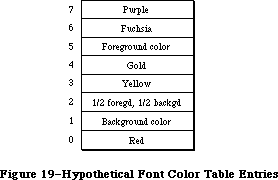 Figure 19–Hypothetical Font Color Table Entries
If no color table is provided, the highest and lowest possible index values for any given screen depth (with a 2-bit screen depth, for example, values 7 and 0) are assigned the foreground and background colors respectively, with the remaining entries given shades in between. This allows gray-scale fonts to be created with as many levels of gray as are needed (since each gray is just a color in between a foreground of black and a background of white) without needing a color table.
_______________________________________________________________________________
»CHARACTERS IN A FONT
_______________________________________________________________________________
Note: The information on the Characters In A Font described in the following
paragraphs was originally documented in Inside Macintosh, Volume I.
A font can consist of up to 255 distinct characters; not all characters need to be defined in a single font. Figure 20 shows the standard printing characters on the Macintosh and their ASCII codes (for example, the ASCII code for “A” is 41 hexadecimal, or 65 decimal).
Note: Codes $00 through $1F and code $7F are normally nonprinting
characters (see the Toolbox Event Manager chapter for details).
The special characters in the system font with codes $11 through $14 can’t normally be typed from the keyboard or keypad. The Font Manager defines constants for these characters:
CONST commandMark = $11; {Command key symbol}
checkMark = $12; {check mark}
diamondMark = $13; {diamond symbol}
appleMark = $14; {apple symbol}
In addition to its maximum of 255 characters, every font contains a missing symbol that’s drawn in case of a request to draw a character that’s missing from the font.
Figure 19–Hypothetical Font Color Table Entries
If no color table is provided, the highest and lowest possible index values for any given screen depth (with a 2-bit screen depth, for example, values 7 and 0) are assigned the foreground and background colors respectively, with the remaining entries given shades in between. This allows gray-scale fonts to be created with as many levels of gray as are needed (since each gray is just a color in between a foreground of black and a background of white) without needing a color table.
_______________________________________________________________________________
»CHARACTERS IN A FONT
_______________________________________________________________________________
Note: The information on the Characters In A Font described in the following
paragraphs was originally documented in Inside Macintosh, Volume I.
A font can consist of up to 255 distinct characters; not all characters need to be defined in a single font. Figure 20 shows the standard printing characters on the Macintosh and their ASCII codes (for example, the ASCII code for “A” is 41 hexadecimal, or 65 decimal).
Note: Codes $00 through $1F and code $7F are normally nonprinting
characters (see the Toolbox Event Manager chapter for details).
The special characters in the system font with codes $11 through $14 can’t normally be typed from the keyboard or keypad. The Font Manager defines constants for these characters:
CONST commandMark = $11; {Command key symbol}
checkMark = $12; {check mark}
diamondMark = $13; {diamond symbol}
appleMark = $14; {apple symbol}
In addition to its maximum of 255 characters, every font contains a missing symbol that’s drawn in case of a request to draw a character that’s missing from the font.
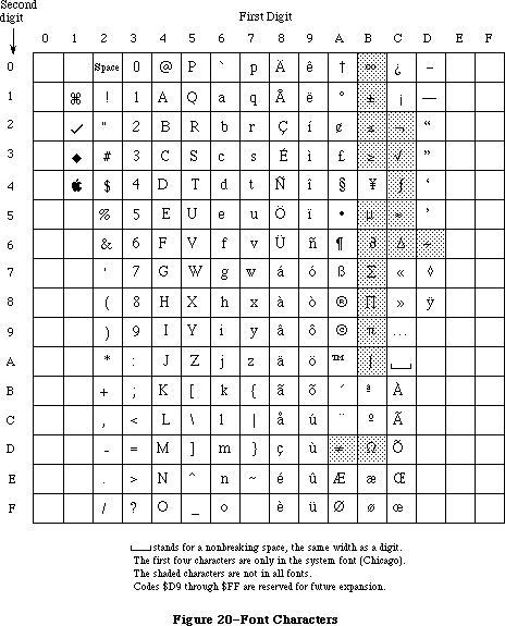 Figure 20–Font Characters
_______________________________________________________________________________
»COMMUNICATION BETWEEN QUICKDRAW AND THE FONT MANAGER
_______________________________________________________________________________
This section describes the data structures that allow QuickDraw and the Font Manager to exchange information. It also discusses the communication that may occur between the Font Manager and the driver of the device on which the characters are being drawn or printed. You can skip this section if you want to change fonts, character style, and font sizes by calling QuickDraw and aren’t interested in the lower-level data structures and routines of the Font Manager. To understand this section fully, you’ll have to be familiar with device drivers and the Device Manager.
Whenever you call a QuickDraw routine that does anything with text, QuickDraw requests information from the Font Manager about the characters. The Font Manager performs any necessary calculations and returns the requested information to QuickDraw. As illustrated in Figure 21, this information exchange occurs via two data structures, a font input record (type FMInput) and a font output record (type FMOutput).
First, QuickDraw passes the Font Manager a font input record:
TYPE FMInput = PACKED RECORD
family: INTEGER; {font number}
size: INTEGER; {font size}
face: Style; {character style}
needBits: BOOLEAN; {TRUE if drawing}
device: INTEGER; {device-specific information}
numer: Point; {numerators of scaling factors}
denom: Point {denominators of scaling factors}
END;
The first three fields contain the font number, size, and character style that QuickDraw wants to use.
The needBits field indicates whether the characters actually will be drawn or not. If the characters are being drawn, all of the information describing the font, including the bit image comprising the characters, will be read into memory. If the characters aren’t being drawn and there’s a resource consisting of only the character widths and general font information, that resource will be read instead.
The high-order byte of the device field contains a device driver reference number. From the driver reference number, the Font Manager can determine the optimum stylistic variations on the font to produce the highest-quality printing or drawing available on a device (as explained below). The low-order byte of the device field is ignored by the Font Manager but may contain information used by the device driver.
Figure 20–Font Characters
_______________________________________________________________________________
»COMMUNICATION BETWEEN QUICKDRAW AND THE FONT MANAGER
_______________________________________________________________________________
This section describes the data structures that allow QuickDraw and the Font Manager to exchange information. It also discusses the communication that may occur between the Font Manager and the driver of the device on which the characters are being drawn or printed. You can skip this section if you want to change fonts, character style, and font sizes by calling QuickDraw and aren’t interested in the lower-level data structures and routines of the Font Manager. To understand this section fully, you’ll have to be familiar with device drivers and the Device Manager.
Whenever you call a QuickDraw routine that does anything with text, QuickDraw requests information from the Font Manager about the characters. The Font Manager performs any necessary calculations and returns the requested information to QuickDraw. As illustrated in Figure 21, this information exchange occurs via two data structures, a font input record (type FMInput) and a font output record (type FMOutput).
First, QuickDraw passes the Font Manager a font input record:
TYPE FMInput = PACKED RECORD
family: INTEGER; {font number}
size: INTEGER; {font size}
face: Style; {character style}
needBits: BOOLEAN; {TRUE if drawing}
device: INTEGER; {device-specific information}
numer: Point; {numerators of scaling factors}
denom: Point {denominators of scaling factors}
END;
The first three fields contain the font number, size, and character style that QuickDraw wants to use.
The needBits field indicates whether the characters actually will be drawn or not. If the characters are being drawn, all of the information describing the font, including the bit image comprising the characters, will be read into memory. If the characters aren’t being drawn and there’s a resource consisting of only the character widths and general font information, that resource will be read instead.
The high-order byte of the device field contains a device driver reference number. From the driver reference number, the Font Manager can determine the optimum stylistic variations on the font to produce the highest-quality printing or drawing available on a device (as explained below). The low-order byte of the device field is ignored by the Font Manager but may contain information used by the device driver.
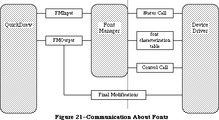 Figure 21–Communication About Fonts
The numer and denom fields contain the scaling factors to be used; numer.v divided by denom.v gives the vertical scaling, and numer.h divided by denom.h gives the horizontal scaling.
The Font Manager takes the font input record and asks the Resource Manager for the font. If the requested size isn’t available, the Font Manager scales another size to match (as described under “Font Scaling”).
Then the Font Manager gets the font characterization table via the device field. If the high-order byte of the device field is 0, the Font Manager gets the screen’s font characterization table (which is stored in the Font Manager). If the high-order byte of the device field is nonzero, the Font Manager calls the status routine of the device driver having that reference number, and the status routine returns a font characterization table. The status routine may use the value of the low-order byte of the device field to determine the font characterization table it should return.
Note: If you want to make your own calls to the device driver’s Status
function, the reference number must be the driver reference number
from the font input record’s device field, csCode must be 8, csParam
must be a pointer to where the device driver should put the font
characterization table, and csParam+4 must be an integer containing
the value of the font input record’s device field.
Figure 22 shows the structure of a font characterization table and, on the right, the values it contains for the Macintosh screen.
Figure 21–Communication About Fonts
The numer and denom fields contain the scaling factors to be used; numer.v divided by denom.v gives the vertical scaling, and numer.h divided by denom.h gives the horizontal scaling.
The Font Manager takes the font input record and asks the Resource Manager for the font. If the requested size isn’t available, the Font Manager scales another size to match (as described under “Font Scaling”).
Then the Font Manager gets the font characterization table via the device field. If the high-order byte of the device field is 0, the Font Manager gets the screen’s font characterization table (which is stored in the Font Manager). If the high-order byte of the device field is nonzero, the Font Manager calls the status routine of the device driver having that reference number, and the status routine returns a font characterization table. The status routine may use the value of the low-order byte of the device field to determine the font characterization table it should return.
Note: If you want to make your own calls to the device driver’s Status
function, the reference number must be the driver reference number
from the font input record’s device field, csCode must be 8, csParam
must be a pointer to where the device driver should put the font
characterization table, and csParam+4 must be an integer containing
the value of the font input record’s device field.
Figure 22 shows the structure of a font characterization table and, on the right, the values it contains for the Macintosh screen.
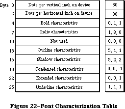 Figure 22–Font Characterization Table
The first two words of the font characterization table contain the approximate number of dots per inch on the device. These values are only used for scaling between devices; they don’t necessarily correspond to a device’s actual resolution.
The remainder of the table consists of three-byte triplets providing information about the different stylistic variations. For all but the triplet defining the underline characteristics:
• The first byte in the triplet indicates which byte beyond the bold
field of the font output record (see below) is affected by the triplet.
• The second byte contains the amount to be stored in the affected field.
• The third byte indicates the amount by which the extra field of the
font output record is to be incremented (starting from 0).
The triplet defining the underline characteristics indicates the amount by which the font output record’s ulOffset, ulShadow, and ulThick fields
(respectively) should be incremented.
Based on the information in the font characterization table, the Font Manager determines the optimum ascent, descent, and leading, so that the highest-quality printing or drawing available will be produced. It then stores this information in a font output record:
TYPE FMOutput = PACKED RECORD
errNum: INTEGER; {not used}
fontHandle: Handle; {handle to font record}
bold: Byte; {bold factor}
italic: Byte; {italic factor}
ulOffset: Byte; {underline offset}
ulShadow: Byte; {underline shadow}
ulThick: Byte; {underline thickness}
shadow: Byte; {shadow factor}
extra: SignedByte; {width of style}
ascent: Byte; {ascent}
descent: Byte; {descent}
widMax: Byte; {maximum character width}
leading: SignedByte; {leading}
unused: Byte; {not used}
numer: Point; {numerators of scaling factors}
denom: Point {denominators of scaling factors}
END;
ErrNum is reserved for future use, and is set to 0. FontHandle is a handle to the font record of the font, as described in the next section. Bold, italic, ulOffset, ulShadow, ulThick, and shadow are all fields that modify the way stylistic variations are done; their values are taken from the font characterization table, and are used by QuickDraw. (You’ll need to experiment with these values if you want to determine exactly how they’re used.) Extra indicates the number of pixels that each character has been widened by stylistic variation. For example, using the screen values shown in Figure 22, the extra field for bold shadowed characters would be 3. Ascent, descent, widMax, and leading are the same as the fields of the FontInfo record returned by the QuickDraw procedure GetFontInfo. Numer and denom contain the scaling factors.
Just before returning this record to QuickDraw, the Font Manager calls the device driver’s control routine to allow the driver to make any final modifications to the record. Finally, the font information is returned to QuickDraw via a pointer to the record, defined as follows:
TYPE FMOutPtr = ^FMOutput;
Note: If you want to make your own calls to the device driver’s Control
function, the reference number must be the driver reference number
from the font input record’s device field, csCode must be 8, csParam
must be a pointer to the font output record, and csParam+4 must be
the value of the font input record’s device field.
_______________________________________________________________________________
»Font Search Algorithm
Note: The extensions to the Font Manager described in the following paragraphs
were originally documented in Inside Macintosh, Volume IV. As such,
this information refers to the 128K ROMs and System file version 3.2
and later.
The basic structure of the font input and output records passed between QuickDraw and the Font Manager is unchanged.
Note: Advanced programmers who use the FMSwapFont function should be aware
that the Font Manager may attach optional tables to the font output
record it returns.
The information QuickDraw passes to the Font Manager includes the font or family number, the font size, and the scaling factors QuickDraw wants to use; the search for an appropriate font is as follows.
The Font Manager first looks for a 'FOND' resource matching the ID of the requested font or font family. It if finds one, it searches the family
record’s font association table (detailed below) for an 'NFNT' or 'FONT' resource matching the requested style and size. It it can match the size but not the style, it returns a font that matches as many properties as possible, giving priority first to italic, then to bold. QuickDraw must then add any needed stylistic variations (using the information passed in the bold, italic, ulOffset, ulShadow, ulThick, and shadow fields of the font output record).
If the Font Manager can’t find a 'FOND' resource, it looks for a 'FONT' resource with the requested font number and size. (It doesn’t look for an 'NFNT' resource since these occur only in conjunction with 'FOND' resources.)
If the Font Manager cannot find a font for a particular style, the font Manager and QuickDraw derive a font (as in the 64K ROM version).
Note: The extensions to the Font Manager described in the following paragraphs
were originally documented in Inside Macintosh, Volume V. As such,
this information refers to the Macintosh SE and Macintosh II ROMs and
System file version 4.1 and later.
When passed a font request, the Font Manager takes a number of steps to provide the desired font; if the font can’t be found, it looks for other fonts with which to fill the request. The search order is as follows:
• a 'FOND' resource. It first checks the last used 'FOND', then checks
the most recently-used width tables (a handle to them is contained in
the global variable WidthListHand), and finally calls GetResource
(looking through the chain of open resource files, beginning with the
application resource file). The width table it checks is that of the
nearest size and font that it found.
• a 'FONT' resource without a corresponding 'FOND' (again calling
GetResource)
• the application font
• a “neighborhood” base font. For fonts numbered below 4096, the
neighborhood base font is 0. For fonts numbered 4096 and above, it
is the next lower font whose number is a multiple of 512.
• the system font
• the Chicago 12 font
_______________________________________________________________________________
»Font Scaling
Note: The information on Font Scaling described in the following paragraphs
was originally documented in Inside Macintosh, Volume I.
The information QuickDraw passes to the Font Manager includes the font size and the scaling factors QuickDraw wants to use. The Font Manager determines the font information it will return to QuickDraw by looking for the exact size needed among the sizes stored for the font. If the exact size requested isn’t available, it then looks for a nearby size that it can scale, as follows:
1. It looks first for a font that’s twice the size, and scales down
that size if there is one.
2. If there’s no font that’s twice the size, it looks for a font
that’s half the size, and scales up that size if there is one.
3. If there’s no font that’s half the size, it looks for a larger
size of the font, and scales down the next larger size if there is one.
4. If there’s no larger size, it looks for a smaller size of the font,
and scales up the closest smaller size if there is one.
5. If the font isn’t available in any size at all, it uses the
application font instead, scaling the font to the size requested.
6. If the application font isn’t available in any size at all, it uses
the system font instead, scaling the font to the size requested.
Scaling looks best when the scaled size is an even multiple of an available size.
Assembly-language note: You can use the global variable FScaleDisable to
disable scaling, if desired. Normally, FScaleDisable
is 0. If you set it to a nonzero value, the Font
Manager will look for the size as described above
but will return the font unscaled.
Note: The extensions to the Font Manager described in the following paragraphs
were originally documented in Inside Macintosh, Volume IV. As such,
this information refers to the 128K ROMs and System file version 3.2
and later.
If the Font Manager can’t find a font of the requested size and font scaling is enabled, it follows the standard scaling algorithm with one exception: If it can’t find a font that’s double or half the requested size, it looks for the font that’s closest to the request size, either larger or smaller.
If it can’t find a font of the requested size and font scaling is disabled, the Font Manager looks for a smaller font closest to the requested size and returns with it with the widths for the requested size. Thus, QuickDraw draws the smaller font with the spacing of the larger, requested font. This is generally preferable to font scaling since it’s faster and more readable. Also, it accurately mirrors the word spacing and line breaks that the document will have when printed, especially if fractional character widths are used.
_______________________________________________________________________________
»Fractional Character Widths
The use of fractional character widths allows more accurate character placement on high-resolution output devices such as the LaserWriter. It also enables character placement on the screen to match more closely that on the LaserWriter (although QuickDraw cannot actually draw a letter 3.5 pixels wide, for
instance). The Font Manager will, however, store the locations of characters more accurately than any particular screen can display. Given exact widths for characters, words, and lines, the LaserWriter can print faster and give better spacing. A price must be paid, however; since screen characters are made up of whole pixels, spacing between characters and words will be uneven as the fractional parts are rounded off. The extent of the distortion depends on the font size relative to the screen resolution.
The Font Manager communicates fractional character widths QuickDraw via the global width table, a data structure allocated in the system heap. The Font Manager gathers the width data for this table from one of three data structures.
Warning: You should always obtain character widths from the global width
table since you can’t really know where the Font Manager obtained
the width information from. A handle to the global width table is
returned by the FontMetrics procedure.
First, it looks for a font character-width table in the font record. In this table, the actual widths of each character in the font are stored in a 16-bit fixed-point format with an integer part in the high-order byte and a fractional part in the low-order byte.
If it doesn’t find this table, it looks in the family record for a family character-width table. For each font in the family, this table contains the fractional widths for every character as if a hypothetical one-point font; the actual values for the characters are calculated by multiplying these widths by the font size. The widths in this table are stored in a 16-bit fixed-point format with an integer part in the high-order 4 bits and a fractional part in the low-order 12 bits.
If no family character-width table is found, the global character widths are derived from the integer widths contained in the offset/width table in the font record.
To use fractional character widths effectively, an application must get accurate widths for the characters, either by using the QuickDraw routine MeasureText or by looking in the global width table.
Warning: Applications that derive their own character widths may not
function properly when fractional widths are enabled.
Note: The extensions to the Font Manager described in the following paragraphs
were originally documented in Inside Macintosh, Volume V. As such,
this information refers to the Macintosh SE and Macintosh II ROMs and
System file version 4.1 and later.
Two cautionary points about how the Font Manager communcates character widths should be added:
• A font request made with scaling disabled will not necessarily return
the same result as an identical request with scaling enabled. The widths
are sure to be the same only if fractional widths are enabled, and if
the font does not have a font character-width table and is a member of
a family record with a family character-width table.
• A font request with either twice the point size or a numerator/denominator
scale factor of 2 is not guaranteed to double the widths of the characters
exactly. Instead, the widths returned accurately describe how QuickDraw
measures and spaces the characters. This is especially noticeable for
algorithmically-applied style modifications like boldfacing. Boldfacing
makes the character strike one pixel wider, regardless of point size. A
font with a family character-width table, however, describes the spacing
of the characters correctly.
To cause two different font requests to measure the same, or proportionately, use the QuickDraw routines SpaceExtra and CharExtra to adjust the widths of the spaces and other characters. In most cases, it’s sufficient to simply pass the difference of the two measures divided by the number of spaces on the line to SpaceExtra. If the difference is too large or small, or if the line does not contain any spaces, you can adjust the line length with the CharExtra routine.
_______________________________________________________________________________
»How QuickDraw Draws Text
Note: The information on How QuickDraw Draws Text described in the following
paragraphs was originally documented in Inside Macintosh, Volume I.
This section provides a conceptual discussion of the steps QuickDraw takes to draw characters (without scaling or stylistic variations such as bold and outline). Basically, QuickDraw simply copies the character image onto the drawing area at a specific location.
1. Take the initial pen location as the character origin for the
first character.
2. In the offset/width table, check the word for the character to
see if it’s –1.
2a. The character exists if the entry in the offset/width table
isn’t –1. Determine the character offset and character width
from this entry. Find the character image at the location in
the bit image specified by the location table. Calculate the
image width by subtracting this word from the succeeding word
in the location table. Determine the number of pixels the
character kerns by adding kernMax to the character offset.
2b. The character is missing if the entry in the offset/width table
is –1; information about the missing symbol is needed. Determine
the missing symbol’s character offset and character width from
the next-to-last word in the offset/width table. Find the missing
symbol at the location in the bit image specified by the next-to-last
word in the location table. Calculate the image width by subtracting
the next-to-last word in the location table from the last word in
the table. Determine the number of pixels the missing symbol kerns
by adding kernMax to the character offset.
3. If the fontType field is fontWid, return to step 2; otherwise, copy
each row of the character image onto the drawing area, one row at a
time. The number of bits to copy from each word is given by the image
width, and the number of words is given by the fRectHeight field.
4. If the fontType field is propFont, move the pen to the right the
number of pixels specified by the character width. If fontType is
fixedFont, move the pen to the right the number of pixels specified
by the widMax field.
5. Return to step 2.
_______________________________________________________________________________
»USING THE FONT MANAGER
_______________________________________________________________________________
The InitFonts procedure initializes the Font Manager; you should call it after initializing QuickDraw but before initializing the Window Manager.
You can set up a menu of fonts in your application by using the Menu Manager procedure AddResMenu (see the Menu Manager chapter for details). When the user chooses a menu item from the font menu, call the Menu Manager procedure GetItem to get the name of the corresponding font, and then the Font Manager function GetFNum to get the font number. The GetFontName function does the reverse of GetFNum: Given a font number, it returns the font name.
In a menu of font sizes in your application, you may want to let the user know which sizes the current font is available in and therefore will not require scaling (this is usually done by showing those font sizes outlined in the menu). You can call the RealFont function to find out whether a font is available in a given size.
If you know you’ll be using a font a lot and don’t want it to be purged, you can use the SetFontLock procedure to make the font unpurgeable during that time.
Advanced programmers who want to write their own font editors or otherwise manipulate fonts can access fonts directly with the FMSwapFont function.
_______________________________________________________________________________
»FONT MANAGER ROUTINES
_______________________________________________________________________________
»Initializing the Font Manager
PROCEDURE InitFonts;
InitFonts initializes the Font Manager. If the system font isn’t already in memory, InitFonts reads it into memory. Call this procedure once before all other Font Manager routines or any Toolbox routine that will call the Font Manager.
_______________________________________________________________________________
»Getting Font Information
Warning: Before returning, the routines in this section issue the Resource
Manager call SetResLoad(TRUE). If your program previously called
SetResLoad(FALSE) and you still want that to be in effect after
calling one of these Font Manager routines, you’ll have to call
SetResLoad(FALSE) again.
PROCEDURE GetFontName (fontNum: INTEGER; VAR theName: Str255);
Assembly-language note: The macro you invoke to call GetFontName from
assembly language is named _GetFName.
GetFontName returns in theName the name of the font having the font number fontNum. If there’s no such font, GetFontName returns the empty string.
PROCEDURE GetFNum (fontName: Str255; VAR theNum: INTEGER);
GetFNum returns in theNum the font number for the font having the given fontName. If there’s no such font, GetFNum returns 0.
FUNCTION RealFont (fontNum: INTEGER; size: INTEGER) : BOOLEAN;
RealFont returns TRUE if the font having the font number fontNum is available in the given size in a resource file, or FALSE if the font has to be scaled to that size.
Note: RealFont will always return FALSE if you pass applFont in fontNum.
To find out if the application font is available in a particular
size, call GetFontName and then GetFNum to get the actual font
number for the application font, and then call RealFont with that number.
_______________________________________________________________________________
»Keeping Fonts in Memory
PROCEDURE SetFontLock (lockFlag: BOOLEAN);
SetFontLock applies to the font in which text was most recently drawn. If lockFlag is TRUE, SetFontLock makes the font unpurgeable (reading it into memory if it isn’t already there). If lockFlag is FALSE, it releases the
memory occupied by the font (by calling the Resource Manager procedure ReleaseResource). Since fonts are normally purgeable, this procedure is useful for making a font temporarily unpurgeable.
_______________________________________________________________________________
»Advanced Routine
The following low-level routine is called by QuickDraw and won’t normally be used by an application directly, but it may be of interest to advanced programmers who want to bypass the QuickDraw routines that deal with text.
FUNCTION FMSwapFont (inRec: FMInput) : FMOutPtr;
FMSwapFont returns a pointer to a font output record containing the size, style, and other information about an adapted version of the font requested in the given font input record. (Font input and output records are explained in the following section.) FMSwapFont is called by QuickDraw every time a QuickDraw routine that does anything with text is used. If you want to call FMSwapFont yourself, you must build a font input record and then use the pointer returned by FMSwapFont to access the resulting font output record.
_______________________________________________________________________________
»Fractional Widths and Scaling
Note: The extensions to the Font Manager described in the following paragraphs
were originally documented in Inside Macintosh, Volume IV. As such,
this information refers to the 128K ROMs and System file version 3.2
and later.
To improve the speed and readability of text display in your application, use the SetFractEnable and SetFScaleDisable procedures to enable fractional character widths and disable font scaling. Certain applications do not work properly when fractional character widths are used and font scaling is disabled, so these features are turned off by default.
The FontMetrics function is much like QuickDraw’s GetFontInfo function except that it returns fixed-point values, letting you draw characters in more precise locations on the screen.
If there’s a 'FOND' resource associated with the most recently drawn font, making the font resource purgeable or unpurgeable with the SetFontLock procedure will make the 'FOND' resource resource purgeable or unpurgeable as well.
PROCEDURE FontMetrics (VAR theMetrics: FMetricRec);
FontMetrics is similar to the QuickDraw procedure GetFontInfo except that it returns fixed-point values for greater accuracy in high-resolution printing.
The FMetricRec data structure is defined as follows:
TYPE FMetricRec = RECORD
ascent: Fixed; {ascent}
descent: Fixed; {descent}
leading: Fixed; {leading}
widMax: Fixed; {maximum character width}
wTabHandle: Handle; {handle to global width table}
END;
Ascent, descent, leading, and widMax are identical in function to their counterparts in GetFontInfo. WTabHandle is a handle to the global width table
(described below).
PROCEDURE SetFractEnable (fractEnable: BOOLEAN) [Not in 64K ROM]
SetFractEnable lets you enable or disable fractional character widths. If fractEnable is TRUE, fractional character widths are enabled; if it’s FALSE, the Font Manager uses integer widths. To ensure compatibility with existing applications, fractional character widths are disabled by default.
SetFractEnable, which was not in the 128K ROM (but was available in the Pascal interfaces) has been added to both the Macintosh SE and Macintosh II ROMs.
Assembly-language note: Assembly-language programmers should call
SetFractEnable rather than change the value
of the global variable FractEnable.
PROCEDURE SetFScaleDisable (fontScaleDisable: BOOLEAN);
SetFScaleDisable lets you disable or enable font scaling. If fontScaleDisable is TRUE, font scaling is disabled and the Font Manager returns an unscaled font with more space around the characters; if it’s FALSE, the Font Manager scales fonts. To ensure compatibility with existing applications, the Font Manager defaults to scaling fonts.
Assembly-language note: All programmers should use the SetFScaleDisable
procedure to disable and enable font scaling. In
particular, setting the global variable FScaleDisable
is insufficient.
_______________________________________________________________________________
»SUMMARY OF THE FONT MANAGER
_______________________________________________________________________________
Constants
CONST
{ Font numbers }
systemFont = 0; {system font}
applFont = 1; {application font}
newYork = 2;
geneva = 3;
monaco = 4;
venice = 5;
london = 6;
athens = 7;
sanFran = 8;
toronto = 9;
cairo = 11;
losAngeles = 12;
times = 20;
helvetica = 21;
courier = 22;
symbol = 23;
taliesin = 24;
{ Special characters }
commandMark = $11; {Command key symbol}
checkMark = $12; {check mark}
diamondMark = $13; {diamond symbol}
appleMark = $14; {apple symbol}
{ Font types [Volume IV addition]}
propFont = $9000; {proportional font}
prpFntH = $9001; { with height table}
prpFntW = $9002; { with width table}
prpFntHW = $9003; { with height & width tables}
fixedFont = $B000; {fixed-width font}
fxdFntH = $B001; { with height table}
fxdFntW = $B002; { with width table}
fxdFntHW = $B003; { with height & width tables}
fontWid = $ACB0; {font width data: 64K ROM only}
_______________________________________________________________________________
Data Types
TYPE
FMInput = PACKED RECORD
family: INTEGER; {font number}
size: INTEGER; {font size}
face: Style; {character style}
needBits: BOOLEAN; {TRUE if drawing}
device: INTEGER; {device-specific information}
numer: Point; {numerators of scaling factors}
denom: Point {denominators of scaling factors}
END;
FMOutPtr = ^FMOutput;
FMOutput = PACKED RECORD
errNum: INTEGER; {not used}
fontHandle: Handle; {handle to font record}
bold: Byte; {bold factor}
italic: Byte; {italic factor}
ulOffset: Byte; {underline offset}
ulShadow: Byte; {underline shadow}
ulThick: Byte; {underline thickness}
shadow: Byte; {shadow factor}
extra: SignedByte; {width of style}
ascent: Byte; {ascent}
descent: Byte; {descent}
widMax: Byte; {maximum character width}
leading: SignedByte; {leading}
unused: Byte; {not used}
numer: Point; {numerators of scaling factors}
denom: Point {denominators of scaling factors}
END;
FontRec = RECORD
fontType: INTEGER; {font type}
firstChar: INTEGER; {ASCII code of first character}
lastChar: INTEGER; {ASCII code of last character}
widMax: INTEGER; {maximum character width}
kernMax: INTEGER; {negative of maximum character kern}
nDescent: INTEGER; {negative of descent}
fRectWidth: INTEGER; {width of font rectangle}
fRectHeight: INTEGER; {height of font rectangle}
owTLoc: INTEGER; {offset to offset/width table}
ascent: INTEGER; {ascent}
descent: INTEGER; {descent}
leading: INTEGER; {leading}
rowWords: INTEGER; {row width of bit image / 2}
{ bitImage: ARRAY[1..rowWords,1..fRectHeight] OF INTEGER; }
{bit image}
{ locTable: ARRAY[firstChar..lastChar+2] OF INTEGER; }
{location table}
{ owTable: ARRAY[firstChar..lastChar+2] OF INTEGER; }
{offset/width table}
{ widthTable: ARRAY[firstChar..lastChar+2] OF INTEGER; }
{width table [Volume IV addition]}
{ heightTable: ARRAY[firstChar..lastChar+2] OF INTEGER; }
{height table [Volume IV addition]}
END;
{Volume IV addition}
FMetricRec = RECORD
ascent: Fixed; {ascent}
descent: Fixed; {descent}
leading: Fixed; {leading}
widMax: Fixed; {maximum character width}
wTabHandle: Handle; {handle to global width table}
END;
FamRec = RECORD
ffFlags: INTEGER; {flags for family}
ffFamID: INTEGER; {family ID number}
ffFirstChar: INTEGER; {ASCII code of the first character}
ffLastChar: INTEGER; {ASCII code of the last character}
ffAscent: INTEGER; {maximum ascent for 1-pt.font}
ffDescent: INTEGER; {maximum descent for 1-pt.font}
ffLeading: INTEGER; {maximum leading for 1-pt.font}
ffWidMax: INTEGER; {maximum width for 1-pt.font}
ffWTabOff: LONGINT; {offset to width table}
ffKernOff: LONGINT; {offset to kerning table}
ffStylOff: LONGINT; {offset to style-mapping table}
ffProperty: ARRAY[1..9] OF INTEGER; {style property info}
ffIntl: ARRAY[1..2] OF INTEGER; {reserved}
ffVersion: INTEGER; {version number}
{ ffAssoc: FontAssoc;} {font association table}
{ ffWidthTab: WidTable;} {width table}
{ ffStyTab: StyleTable;}{style-mapping table}
{ ffKernTab: KernTable;} {kerning table}
END;
WidthTable = RECORD
tabData: ARRAY[1..256] OF Fixed; { character widths}
tabFont: Handle; {font record used to build table}
sExtra: LONGINT; {space extra used for table}
style: LONGINT; {extra due to style}
fID: INTEGER; {font family ID}
fSize: INTEGER; {font size request}
face: INTEGER; {style (face) request}
device: INTEGER; {device requested}
inNumer: Point; {numerators of scaling factors}
inDenom: Point; {denominators of scaling factors}
aFID: INTEGER; {actual font family ID for table}
fHand: handle; {family record used to build table}
usedFam: BOOLEAN; {used fixed-point family widths}
aFace: Byte; {actual face produced}
vOutput: INTEGER; {vertical factor for expanding }
{ characters}
hOutput: INTEGER; {horizontal factor for expanding }
{ characters}
vFactor: INTEGER; {not used}
hFactor: INTEGER; {horizontal factor for increasing }
{ character widths}
aSize: INTEGER; {actual size of actual font used}
tabSize: INTEGER {total size of table}
END;
_______________________________________________________________________________
Routines
Initializing the Font Manager
PROCEDURE InitFonts;
Getting Font Information
PROCEDURE GetFontName (fontNum: INTEGER; VAR theName: Str255);
PROCEDURE GetFNum (fontName: Str255; VAR theNum: INTEGER);
FUNCTION RealFont (fontNum: INTEGER; size: INTEGER) : BOOLEAN;
Keeping Fonts in Memory
PROCEDURE SetFontLock (lockFlag: BOOLEAN);
Advanced Routine
FUNCTION FMSwapFont (inRec: FMInput) : FMOutPtr;
Fractional Widths and Scaling [Volume IV addition]
PROCEDURE FontMetrics (VAR theMetrics: FMetricRec);
PROCEDURE SetFScaleDisable (fontScaleDisable: BOOLEAN);
PROCEDURE SetFractEnable (fractEnable: BOOLEAN); [Not in 64K ROM]
_______________________________________________________________________________
Assembly-Language Information
Constants
; Font numbers
sysFont .EQU 0 ;system font
applFont .EQU 1 ;application font
newYork .EQU 2
geneva .EQU 3
monaco .EQU 4
venice .EQU 5
london .EQU 6
athens .EQU 7
sanFran .EQU 8
toronto .EQU 9
cairo .EQU 11
losAngeles .EQU 12
times .EQU 20
helvetica .EQU 21
courier .EQU 22
symbol .EQU 23
taliesin .EQU 24
; Special characters
commandMark .EQU $11 ;Command key symbol
checkMark .EQU $12 ;check mark
diamondMark .EQU $13 ;diamond symbol
appleMark .EQU $14 ;apple symbol
; Font types [Volume IV addition]
propFont .EQU $9000 ;proportional font
prpFntH .EQU $9001 ; with height table
prpFntW .EQU $9002 ; with width table
prpFntHW .EQU $9003 ; with height & width tables
fixedFont .EQU $B000 ;fixed-width font
fxdFntH .EQU $B001 ; with height table
fxdFntW .EQU $B002 ; with width table
fxdFntHW .EQU $B003 ; with height & width tables
fontWid .EQU $ACB0 ;font width data
; Control and Status call code
fMgrCtl1 .EQU 8 ;code used to get and modify font
; characterization table
Font Input Record Data Structure
fmInFamily Font number (word)
fmInSize Font size (word)
fmInFace Character style (word)
fmInNeedBits Nonzero if drawing (byte)
fmInDevice Device-specific information (byte)
fmInNumer Numerators of scaling factors (point; long)
fmInDenom Denominators of scaling factors (point; long)
Font Output Record Data Structure
fmOutFontH Handle to font record
fmOutBold Bold factor (byte)
fmOutItalic Italic factor (byte)
fmOutUlOffset Underline offset (byte)
fmOutUlShadow Underline shadow (byte)
fmOutUlThick Underline thickness (byte)
fmOutShadow Shadow factor (byte)
fmOutExtra Width of style (byte)
fmOutAscent Ascent (byte)
fmOutDescent Descent (byte)
fmOutWidMax Maximum character width (byte)
fmOutLeading Leading (byte)
fmOutNumer Numerators of scaling factors (point; long)
fmOutDenom Denominators of scaling factors (point; long)
Font Metric Record Data Structure [Volume IV addition]
ascent Ascent (word)
descent Descent (word)
leading Leading (word)
widMax Maximum character width (word)
wTabHandle Handle to global width table (long)
Font Record ('FONT' or 'NFNT') Data Structure [Volume IV addition]
fFontType Font type (word)
fFirstChar ASCII code of first character (word)
fLastChar ASCII code of last character (word)
fWidMax Maximum character width (word)
fKernMax Negative of maximum character kern (word)
fNDescent Negative of descent (word)
fFRectWidth Width of font rectangle (word)
fFRectHeight Height of font rectangle (word)
fOWTLoc Offset to offset/width table (word)
fAscent Ascent (word)
fDescent Descent (word)
fLeading Leading (word)
fRowWords Row width of bit image / 2 (word)
Family Record ('FOND') Data Structure [Volume IV addition]
fondFlags Flags for family (word)
fondFamID Family ID number (word)
fondFirst ASCII code of first character (word)
fondLast ASCII code of last character (word)
fondAscent Maximum ascent expressed for 1 pt. font (word)
fondDescent Maximum descent expressed for 1 pt. font (word)
fondLeading Maximum leading expressed for 1 pt. font (word)
fondWidMax Maximum widMax expressed for 1 pt. font (word)
fondWTabOff Offset to width table (long)
fondKernOff Offset to kerning table (long)
fondStylOff Offset to style-mapping table (long)
fondProperty Style property info (12 words)
fondIntl Reserved (3 words)
fondAssoc Font association Table (variable length)
fondWidTab Optional character-width table (variable length)
fondStylTab Style-mapping table (variable length)
fondKerntab Kerning table (variable length)
Global Width Table Data Structure [Volume IV addition]
widTabData Character widths (1024 bytes)
widTabFont Font handle used to build table (long)
widthSExtra Space extra used for table (long)
widthStyle Extra due to style (long)
widthFID Font family ID (word)
widthFSize Font size request (word)
widthFace Style (face) request (word)
widthDevice Device requested (word)
inNumer Numerators of scaling factors (long)
inDenom Denominators of scaling factors (long)
widthAFID Actual font family ID for table (word)
widthFHand Font family handle for table (long)
widthUsedFam Used fixed point family widths? (boolean)
widthAFace Actual face produced (byte)
widthVOutput Not used (word)
widthHOutput Horizontal factor for increasing character widths (word)
widthVFactor Vertical scale output value (word)
widthHFactor Horizontal scale output value (word)
widthASize Actual size of actual font used (word)
widTabSize Total size of table (word)
Special Macro Names
Pascal name Macro name
GetFontName _GetFName
Variables
ApFontID Font number of application font (word)
FScaleDisable Nonzero to disable scaling (byte)
ROMFont0 Handle to font record for system font
Volume IV addition
FractEnable Nonzero to enable fractional widths (byte)
IntlSpec International software installed if greater than 0 (long)
WidthListHand Handle to a list of handles to recently-used width tables
WidthPtr Pointer to global width table
WidthTabHandle Handle to global width table
SysFontFam If nonzero, the font number to use for system font (byte)
SysFontSiz If nonzero, the size of the system font (byte)
LastFOND Handle to last family record used
Volume V addition
SynListHandle Handle to synthetic font list
Further Reference:
_______________________________________________________________________________
Resource Manager
QuickDraw
Device Manager
Technical Note #26, Character vs. String Operations in QuickDraw
Technical Note #30, Font Height Tables
Technical Note #191, Font Names
Technical Note #198, Font/DA Mover, Styled Fonts, and 'NFNT's
Technical Note #245, Font Family Numbers
Figure 22–Font Characterization Table
The first two words of the font characterization table contain the approximate number of dots per inch on the device. These values are only used for scaling between devices; they don’t necessarily correspond to a device’s actual resolution.
The remainder of the table consists of three-byte triplets providing information about the different stylistic variations. For all but the triplet defining the underline characteristics:
• The first byte in the triplet indicates which byte beyond the bold
field of the font output record (see below) is affected by the triplet.
• The second byte contains the amount to be stored in the affected field.
• The third byte indicates the amount by which the extra field of the
font output record is to be incremented (starting from 0).
The triplet defining the underline characteristics indicates the amount by which the font output record’s ulOffset, ulShadow, and ulThick fields
(respectively) should be incremented.
Based on the information in the font characterization table, the Font Manager determines the optimum ascent, descent, and leading, so that the highest-quality printing or drawing available will be produced. It then stores this information in a font output record:
TYPE FMOutput = PACKED RECORD
errNum: INTEGER; {not used}
fontHandle: Handle; {handle to font record}
bold: Byte; {bold factor}
italic: Byte; {italic factor}
ulOffset: Byte; {underline offset}
ulShadow: Byte; {underline shadow}
ulThick: Byte; {underline thickness}
shadow: Byte; {shadow factor}
extra: SignedByte; {width of style}
ascent: Byte; {ascent}
descent: Byte; {descent}
widMax: Byte; {maximum character width}
leading: SignedByte; {leading}
unused: Byte; {not used}
numer: Point; {numerators of scaling factors}
denom: Point {denominators of scaling factors}
END;
ErrNum is reserved for future use, and is set to 0. FontHandle is a handle to the font record of the font, as described in the next section. Bold, italic, ulOffset, ulShadow, ulThick, and shadow are all fields that modify the way stylistic variations are done; their values are taken from the font characterization table, and are used by QuickDraw. (You’ll need to experiment with these values if you want to determine exactly how they’re used.) Extra indicates the number of pixels that each character has been widened by stylistic variation. For example, using the screen values shown in Figure 22, the extra field for bold shadowed characters would be 3. Ascent, descent, widMax, and leading are the same as the fields of the FontInfo record returned by the QuickDraw procedure GetFontInfo. Numer and denom contain the scaling factors.
Just before returning this record to QuickDraw, the Font Manager calls the device driver’s control routine to allow the driver to make any final modifications to the record. Finally, the font information is returned to QuickDraw via a pointer to the record, defined as follows:
TYPE FMOutPtr = ^FMOutput;
Note: If you want to make your own calls to the device driver’s Control
function, the reference number must be the driver reference number
from the font input record’s device field, csCode must be 8, csParam
must be a pointer to the font output record, and csParam+4 must be
the value of the font input record’s device field.
_______________________________________________________________________________
»Font Search Algorithm
Note: The extensions to the Font Manager described in the following paragraphs
were originally documented in Inside Macintosh, Volume IV. As such,
this information refers to the 128K ROMs and System file version 3.2
and later.
The basic structure of the font input and output records passed between QuickDraw and the Font Manager is unchanged.
Note: Advanced programmers who use the FMSwapFont function should be aware
that the Font Manager may attach optional tables to the font output
record it returns.
The information QuickDraw passes to the Font Manager includes the font or family number, the font size, and the scaling factors QuickDraw wants to use; the search for an appropriate font is as follows.
The Font Manager first looks for a 'FOND' resource matching the ID of the requested font or font family. It if finds one, it searches the family
record’s font association table (detailed below) for an 'NFNT' or 'FONT' resource matching the requested style and size. It it can match the size but not the style, it returns a font that matches as many properties as possible, giving priority first to italic, then to bold. QuickDraw must then add any needed stylistic variations (using the information passed in the bold, italic, ulOffset, ulShadow, ulThick, and shadow fields of the font output record).
If the Font Manager can’t find a 'FOND' resource, it looks for a 'FONT' resource with the requested font number and size. (It doesn’t look for an 'NFNT' resource since these occur only in conjunction with 'FOND' resources.)
If the Font Manager cannot find a font for a particular style, the font Manager and QuickDraw derive a font (as in the 64K ROM version).
Note: The extensions to the Font Manager described in the following paragraphs
were originally documented in Inside Macintosh, Volume V. As such,
this information refers to the Macintosh SE and Macintosh II ROMs and
System file version 4.1 and later.
When passed a font request, the Font Manager takes a number of steps to provide the desired font; if the font can’t be found, it looks for other fonts with which to fill the request. The search order is as follows:
• a 'FOND' resource. It first checks the last used 'FOND', then checks
the most recently-used width tables (a handle to them is contained in
the global variable WidthListHand), and finally calls GetResource
(looking through the chain of open resource files, beginning with the
application resource file). The width table it checks is that of the
nearest size and font that it found.
• a 'FONT' resource without a corresponding 'FOND' (again calling
GetResource)
• the application font
• a “neighborhood” base font. For fonts numbered below 4096, the
neighborhood base font is 0. For fonts numbered 4096 and above, it
is the next lower font whose number is a multiple of 512.
• the system font
• the Chicago 12 font
_______________________________________________________________________________
»Font Scaling
Note: The information on Font Scaling described in the following paragraphs
was originally documented in Inside Macintosh, Volume I.
The information QuickDraw passes to the Font Manager includes the font size and the scaling factors QuickDraw wants to use. The Font Manager determines the font information it will return to QuickDraw by looking for the exact size needed among the sizes stored for the font. If the exact size requested isn’t available, it then looks for a nearby size that it can scale, as follows:
1. It looks first for a font that’s twice the size, and scales down
that size if there is one.
2. If there’s no font that’s twice the size, it looks for a font
that’s half the size, and scales up that size if there is one.
3. If there’s no font that’s half the size, it looks for a larger
size of the font, and scales down the next larger size if there is one.
4. If there’s no larger size, it looks for a smaller size of the font,
and scales up the closest smaller size if there is one.
5. If the font isn’t available in any size at all, it uses the
application font instead, scaling the font to the size requested.
6. If the application font isn’t available in any size at all, it uses
the system font instead, scaling the font to the size requested.
Scaling looks best when the scaled size is an even multiple of an available size.
Assembly-language note: You can use the global variable FScaleDisable to
disable scaling, if desired. Normally, FScaleDisable
is 0. If you set it to a nonzero value, the Font
Manager will look for the size as described above
but will return the font unscaled.
Note: The extensions to the Font Manager described in the following paragraphs
were originally documented in Inside Macintosh, Volume IV. As such,
this information refers to the 128K ROMs and System file version 3.2
and later.
If the Font Manager can’t find a font of the requested size and font scaling is enabled, it follows the standard scaling algorithm with one exception: If it can’t find a font that’s double or half the requested size, it looks for the font that’s closest to the request size, either larger or smaller.
If it can’t find a font of the requested size and font scaling is disabled, the Font Manager looks for a smaller font closest to the requested size and returns with it with the widths for the requested size. Thus, QuickDraw draws the smaller font with the spacing of the larger, requested font. This is generally preferable to font scaling since it’s faster and more readable. Also, it accurately mirrors the word spacing and line breaks that the document will have when printed, especially if fractional character widths are used.
_______________________________________________________________________________
»Fractional Character Widths
The use of fractional character widths allows more accurate character placement on high-resolution output devices such as the LaserWriter. It also enables character placement on the screen to match more closely that on the LaserWriter (although QuickDraw cannot actually draw a letter 3.5 pixels wide, for
instance). The Font Manager will, however, store the locations of characters more accurately than any particular screen can display. Given exact widths for characters, words, and lines, the LaserWriter can print faster and give better spacing. A price must be paid, however; since screen characters are made up of whole pixels, spacing between characters and words will be uneven as the fractional parts are rounded off. The extent of the distortion depends on the font size relative to the screen resolution.
The Font Manager communicates fractional character widths QuickDraw via the global width table, a data structure allocated in the system heap. The Font Manager gathers the width data for this table from one of three data structures.
Warning: You should always obtain character widths from the global width
table since you can’t really know where the Font Manager obtained
the width information from. A handle to the global width table is
returned by the FontMetrics procedure.
First, it looks for a font character-width table in the font record. In this table, the actual widths of each character in the font are stored in a 16-bit fixed-point format with an integer part in the high-order byte and a fractional part in the low-order byte.
If it doesn’t find this table, it looks in the family record for a family character-width table. For each font in the family, this table contains the fractional widths for every character as if a hypothetical one-point font; the actual values for the characters are calculated by multiplying these widths by the font size. The widths in this table are stored in a 16-bit fixed-point format with an integer part in the high-order 4 bits and a fractional part in the low-order 12 bits.
If no family character-width table is found, the global character widths are derived from the integer widths contained in the offset/width table in the font record.
To use fractional character widths effectively, an application must get accurate widths for the characters, either by using the QuickDraw routine MeasureText or by looking in the global width table.
Warning: Applications that derive their own character widths may not
function properly when fractional widths are enabled.
Note: The extensions to the Font Manager described in the following paragraphs
were originally documented in Inside Macintosh, Volume V. As such,
this information refers to the Macintosh SE and Macintosh II ROMs and
System file version 4.1 and later.
Two cautionary points about how the Font Manager communcates character widths should be added:
• A font request made with scaling disabled will not necessarily return
the same result as an identical request with scaling enabled. The widths
are sure to be the same only if fractional widths are enabled, and if
the font does not have a font character-width table and is a member of
a family record with a family character-width table.
• A font request with either twice the point size or a numerator/denominator
scale factor of 2 is not guaranteed to double the widths of the characters
exactly. Instead, the widths returned accurately describe how QuickDraw
measures and spaces the characters. This is especially noticeable for
algorithmically-applied style modifications like boldfacing. Boldfacing
makes the character strike one pixel wider, regardless of point size. A
font with a family character-width table, however, describes the spacing
of the characters correctly.
To cause two different font requests to measure the same, or proportionately, use the QuickDraw routines SpaceExtra and CharExtra to adjust the widths of the spaces and other characters. In most cases, it’s sufficient to simply pass the difference of the two measures divided by the number of spaces on the line to SpaceExtra. If the difference is too large or small, or if the line does not contain any spaces, you can adjust the line length with the CharExtra routine.
_______________________________________________________________________________
»How QuickDraw Draws Text
Note: The information on How QuickDraw Draws Text described in the following
paragraphs was originally documented in Inside Macintosh, Volume I.
This section provides a conceptual discussion of the steps QuickDraw takes to draw characters (without scaling or stylistic variations such as bold and outline). Basically, QuickDraw simply copies the character image onto the drawing area at a specific location.
1. Take the initial pen location as the character origin for the
first character.
2. In the offset/width table, check the word for the character to
see if it’s –1.
2a. The character exists if the entry in the offset/width table
isn’t –1. Determine the character offset and character width
from this entry. Find the character image at the location in
the bit image specified by the location table. Calculate the
image width by subtracting this word from the succeeding word
in the location table. Determine the number of pixels the
character kerns by adding kernMax to the character offset.
2b. The character is missing if the entry in the offset/width table
is –1; information about the missing symbol is needed. Determine
the missing symbol’s character offset and character width from
the next-to-last word in the offset/width table. Find the missing
symbol at the location in the bit image specified by the next-to-last
word in the location table. Calculate the image width by subtracting
the next-to-last word in the location table from the last word in
the table. Determine the number of pixels the missing symbol kerns
by adding kernMax to the character offset.
3. If the fontType field is fontWid, return to step 2; otherwise, copy
each row of the character image onto the drawing area, one row at a
time. The number of bits to copy from each word is given by the image
width, and the number of words is given by the fRectHeight field.
4. If the fontType field is propFont, move the pen to the right the
number of pixels specified by the character width. If fontType is
fixedFont, move the pen to the right the number of pixels specified
by the widMax field.
5. Return to step 2.
_______________________________________________________________________________
»USING THE FONT MANAGER
_______________________________________________________________________________
The InitFonts procedure initializes the Font Manager; you should call it after initializing QuickDraw but before initializing the Window Manager.
You can set up a menu of fonts in your application by using the Menu Manager procedure AddResMenu (see the Menu Manager chapter for details). When the user chooses a menu item from the font menu, call the Menu Manager procedure GetItem to get the name of the corresponding font, and then the Font Manager function GetFNum to get the font number. The GetFontName function does the reverse of GetFNum: Given a font number, it returns the font name.
In a menu of font sizes in your application, you may want to let the user know which sizes the current font is available in and therefore will not require scaling (this is usually done by showing those font sizes outlined in the menu). You can call the RealFont function to find out whether a font is available in a given size.
If you know you’ll be using a font a lot and don’t want it to be purged, you can use the SetFontLock procedure to make the font unpurgeable during that time.
Advanced programmers who want to write their own font editors or otherwise manipulate fonts can access fonts directly with the FMSwapFont function.
_______________________________________________________________________________
»FONT MANAGER ROUTINES
_______________________________________________________________________________
»Initializing the Font Manager
PROCEDURE InitFonts;
InitFonts initializes the Font Manager. If the system font isn’t already in memory, InitFonts reads it into memory. Call this procedure once before all other Font Manager routines or any Toolbox routine that will call the Font Manager.
_______________________________________________________________________________
»Getting Font Information
Warning: Before returning, the routines in this section issue the Resource
Manager call SetResLoad(TRUE). If your program previously called
SetResLoad(FALSE) and you still want that to be in effect after
calling one of these Font Manager routines, you’ll have to call
SetResLoad(FALSE) again.
PROCEDURE GetFontName (fontNum: INTEGER; VAR theName: Str255);
Assembly-language note: The macro you invoke to call GetFontName from
assembly language is named _GetFName.
GetFontName returns in theName the name of the font having the font number fontNum. If there’s no such font, GetFontName returns the empty string.
PROCEDURE GetFNum (fontName: Str255; VAR theNum: INTEGER);
GetFNum returns in theNum the font number for the font having the given fontName. If there’s no such font, GetFNum returns 0.
FUNCTION RealFont (fontNum: INTEGER; size: INTEGER) : BOOLEAN;
RealFont returns TRUE if the font having the font number fontNum is available in the given size in a resource file, or FALSE if the font has to be scaled to that size.
Note: RealFont will always return FALSE if you pass applFont in fontNum.
To find out if the application font is available in a particular
size, call GetFontName and then GetFNum to get the actual font
number for the application font, and then call RealFont with that number.
_______________________________________________________________________________
»Keeping Fonts in Memory
PROCEDURE SetFontLock (lockFlag: BOOLEAN);
SetFontLock applies to the font in which text was most recently drawn. If lockFlag is TRUE, SetFontLock makes the font unpurgeable (reading it into memory if it isn’t already there). If lockFlag is FALSE, it releases the
memory occupied by the font (by calling the Resource Manager procedure ReleaseResource). Since fonts are normally purgeable, this procedure is useful for making a font temporarily unpurgeable.
_______________________________________________________________________________
»Advanced Routine
The following low-level routine is called by QuickDraw and won’t normally be used by an application directly, but it may be of interest to advanced programmers who want to bypass the QuickDraw routines that deal with text.
FUNCTION FMSwapFont (inRec: FMInput) : FMOutPtr;
FMSwapFont returns a pointer to a font output record containing the size, style, and other information about an adapted version of the font requested in the given font input record. (Font input and output records are explained in the following section.) FMSwapFont is called by QuickDraw every time a QuickDraw routine that does anything with text is used. If you want to call FMSwapFont yourself, you must build a font input record and then use the pointer returned by FMSwapFont to access the resulting font output record.
_______________________________________________________________________________
»Fractional Widths and Scaling
Note: The extensions to the Font Manager described in the following paragraphs
were originally documented in Inside Macintosh, Volume IV. As such,
this information refers to the 128K ROMs and System file version 3.2
and later.
To improve the speed and readability of text display in your application, use the SetFractEnable and SetFScaleDisable procedures to enable fractional character widths and disable font scaling. Certain applications do not work properly when fractional character widths are used and font scaling is disabled, so these features are turned off by default.
The FontMetrics function is much like QuickDraw’s GetFontInfo function except that it returns fixed-point values, letting you draw characters in more precise locations on the screen.
If there’s a 'FOND' resource associated with the most recently drawn font, making the font resource purgeable or unpurgeable with the SetFontLock procedure will make the 'FOND' resource resource purgeable or unpurgeable as well.
PROCEDURE FontMetrics (VAR theMetrics: FMetricRec);
FontMetrics is similar to the QuickDraw procedure GetFontInfo except that it returns fixed-point values for greater accuracy in high-resolution printing.
The FMetricRec data structure is defined as follows:
TYPE FMetricRec = RECORD
ascent: Fixed; {ascent}
descent: Fixed; {descent}
leading: Fixed; {leading}
widMax: Fixed; {maximum character width}
wTabHandle: Handle; {handle to global width table}
END;
Ascent, descent, leading, and widMax are identical in function to their counterparts in GetFontInfo. WTabHandle is a handle to the global width table
(described below).
PROCEDURE SetFractEnable (fractEnable: BOOLEAN) [Not in 64K ROM]
SetFractEnable lets you enable or disable fractional character widths. If fractEnable is TRUE, fractional character widths are enabled; if it’s FALSE, the Font Manager uses integer widths. To ensure compatibility with existing applications, fractional character widths are disabled by default.
SetFractEnable, which was not in the 128K ROM (but was available in the Pascal interfaces) has been added to both the Macintosh SE and Macintosh II ROMs.
Assembly-language note: Assembly-language programmers should call
SetFractEnable rather than change the value
of the global variable FractEnable.
PROCEDURE SetFScaleDisable (fontScaleDisable: BOOLEAN);
SetFScaleDisable lets you disable or enable font scaling. If fontScaleDisable is TRUE, font scaling is disabled and the Font Manager returns an unscaled font with more space around the characters; if it’s FALSE, the Font Manager scales fonts. To ensure compatibility with existing applications, the Font Manager defaults to scaling fonts.
Assembly-language note: All programmers should use the SetFScaleDisable
procedure to disable and enable font scaling. In
particular, setting the global variable FScaleDisable
is insufficient.
_______________________________________________________________________________
»SUMMARY OF THE FONT MANAGER
_______________________________________________________________________________
Constants
CONST
{ Font numbers }
systemFont = 0; {system font}
applFont = 1; {application font}
newYork = 2;
geneva = 3;
monaco = 4;
venice = 5;
london = 6;
athens = 7;
sanFran = 8;
toronto = 9;
cairo = 11;
losAngeles = 12;
times = 20;
helvetica = 21;
courier = 22;
symbol = 23;
taliesin = 24;
{ Special characters }
commandMark = $11; {Command key symbol}
checkMark = $12; {check mark}
diamondMark = $13; {diamond symbol}
appleMark = $14; {apple symbol}
{ Font types [Volume IV addition]}
propFont = $9000; {proportional font}
prpFntH = $9001; { with height table}
prpFntW = $9002; { with width table}
prpFntHW = $9003; { with height & width tables}
fixedFont = $B000; {fixed-width font}
fxdFntH = $B001; { with height table}
fxdFntW = $B002; { with width table}
fxdFntHW = $B003; { with height & width tables}
fontWid = $ACB0; {font width data: 64K ROM only}
_______________________________________________________________________________
Data Types
TYPE
FMInput = PACKED RECORD
family: INTEGER; {font number}
size: INTEGER; {font size}
face: Style; {character style}
needBits: BOOLEAN; {TRUE if drawing}
device: INTEGER; {device-specific information}
numer: Point; {numerators of scaling factors}
denom: Point {denominators of scaling factors}
END;
FMOutPtr = ^FMOutput;
FMOutput = PACKED RECORD
errNum: INTEGER; {not used}
fontHandle: Handle; {handle to font record}
bold: Byte; {bold factor}
italic: Byte; {italic factor}
ulOffset: Byte; {underline offset}
ulShadow: Byte; {underline shadow}
ulThick: Byte; {underline thickness}
shadow: Byte; {shadow factor}
extra: SignedByte; {width of style}
ascent: Byte; {ascent}
descent: Byte; {descent}
widMax: Byte; {maximum character width}
leading: SignedByte; {leading}
unused: Byte; {not used}
numer: Point; {numerators of scaling factors}
denom: Point {denominators of scaling factors}
END;
FontRec = RECORD
fontType: INTEGER; {font type}
firstChar: INTEGER; {ASCII code of first character}
lastChar: INTEGER; {ASCII code of last character}
widMax: INTEGER; {maximum character width}
kernMax: INTEGER; {negative of maximum character kern}
nDescent: INTEGER; {negative of descent}
fRectWidth: INTEGER; {width of font rectangle}
fRectHeight: INTEGER; {height of font rectangle}
owTLoc: INTEGER; {offset to offset/width table}
ascent: INTEGER; {ascent}
descent: INTEGER; {descent}
leading: INTEGER; {leading}
rowWords: INTEGER; {row width of bit image / 2}
{ bitImage: ARRAY[1..rowWords,1..fRectHeight] OF INTEGER; }
{bit image}
{ locTable: ARRAY[firstChar..lastChar+2] OF INTEGER; }
{location table}
{ owTable: ARRAY[firstChar..lastChar+2] OF INTEGER; }
{offset/width table}
{ widthTable: ARRAY[firstChar..lastChar+2] OF INTEGER; }
{width table [Volume IV addition]}
{ heightTable: ARRAY[firstChar..lastChar+2] OF INTEGER; }
{height table [Volume IV addition]}
END;
{Volume IV addition}
FMetricRec = RECORD
ascent: Fixed; {ascent}
descent: Fixed; {descent}
leading: Fixed; {leading}
widMax: Fixed; {maximum character width}
wTabHandle: Handle; {handle to global width table}
END;
FamRec = RECORD
ffFlags: INTEGER; {flags for family}
ffFamID: INTEGER; {family ID number}
ffFirstChar: INTEGER; {ASCII code of the first character}
ffLastChar: INTEGER; {ASCII code of the last character}
ffAscent: INTEGER; {maximum ascent for 1-pt.font}
ffDescent: INTEGER; {maximum descent for 1-pt.font}
ffLeading: INTEGER; {maximum leading for 1-pt.font}
ffWidMax: INTEGER; {maximum width for 1-pt.font}
ffWTabOff: LONGINT; {offset to width table}
ffKernOff: LONGINT; {offset to kerning table}
ffStylOff: LONGINT; {offset to style-mapping table}
ffProperty: ARRAY[1..9] OF INTEGER; {style property info}
ffIntl: ARRAY[1..2] OF INTEGER; {reserved}
ffVersion: INTEGER; {version number}
{ ffAssoc: FontAssoc;} {font association table}
{ ffWidthTab: WidTable;} {width table}
{ ffStyTab: StyleTable;}{style-mapping table}
{ ffKernTab: KernTable;} {kerning table}
END;
WidthTable = RECORD
tabData: ARRAY[1..256] OF Fixed; { character widths}
tabFont: Handle; {font record used to build table}
sExtra: LONGINT; {space extra used for table}
style: LONGINT; {extra due to style}
fID: INTEGER; {font family ID}
fSize: INTEGER; {font size request}
face: INTEGER; {style (face) request}
device: INTEGER; {device requested}
inNumer: Point; {numerators of scaling factors}
inDenom: Point; {denominators of scaling factors}
aFID: INTEGER; {actual font family ID for table}
fHand: handle; {family record used to build table}
usedFam: BOOLEAN; {used fixed-point family widths}
aFace: Byte; {actual face produced}
vOutput: INTEGER; {vertical factor for expanding }
{ characters}
hOutput: INTEGER; {horizontal factor for expanding }
{ characters}
vFactor: INTEGER; {not used}
hFactor: INTEGER; {horizontal factor for increasing }
{ character widths}
aSize: INTEGER; {actual size of actual font used}
tabSize: INTEGER {total size of table}
END;
_______________________________________________________________________________
Routines
Initializing the Font Manager
PROCEDURE InitFonts;
Getting Font Information
PROCEDURE GetFontName (fontNum: INTEGER; VAR theName: Str255);
PROCEDURE GetFNum (fontName: Str255; VAR theNum: INTEGER);
FUNCTION RealFont (fontNum: INTEGER; size: INTEGER) : BOOLEAN;
Keeping Fonts in Memory
PROCEDURE SetFontLock (lockFlag: BOOLEAN);
Advanced Routine
FUNCTION FMSwapFont (inRec: FMInput) : FMOutPtr;
Fractional Widths and Scaling [Volume IV addition]
PROCEDURE FontMetrics (VAR theMetrics: FMetricRec);
PROCEDURE SetFScaleDisable (fontScaleDisable: BOOLEAN);
PROCEDURE SetFractEnable (fractEnable: BOOLEAN); [Not in 64K ROM]
_______________________________________________________________________________
Assembly-Language Information
Constants
; Font numbers
sysFont .EQU 0 ;system font
applFont .EQU 1 ;application font
newYork .EQU 2
geneva .EQU 3
monaco .EQU 4
venice .EQU 5
london .EQU 6
athens .EQU 7
sanFran .EQU 8
toronto .EQU 9
cairo .EQU 11
losAngeles .EQU 12
times .EQU 20
helvetica .EQU 21
courier .EQU 22
symbol .EQU 23
taliesin .EQU 24
; Special characters
commandMark .EQU $11 ;Command key symbol
checkMark .EQU $12 ;check mark
diamondMark .EQU $13 ;diamond symbol
appleMark .EQU $14 ;apple symbol
; Font types [Volume IV addition]
propFont .EQU $9000 ;proportional font
prpFntH .EQU $9001 ; with height table
prpFntW .EQU $9002 ; with width table
prpFntHW .EQU $9003 ; with height & width tables
fixedFont .EQU $B000 ;fixed-width font
fxdFntH .EQU $B001 ; with height table
fxdFntW .EQU $B002 ; with width table
fxdFntHW .EQU $B003 ; with height & width tables
fontWid .EQU $ACB0 ;font width data
; Control and Status call code
fMgrCtl1 .EQU 8 ;code used to get and modify font
; characterization table
Font Input Record Data Structure
fmInFamily Font number (word)
fmInSize Font size (word)
fmInFace Character style (word)
fmInNeedBits Nonzero if drawing (byte)
fmInDevice Device-specific information (byte)
fmInNumer Numerators of scaling factors (point; long)
fmInDenom Denominators of scaling factors (point; long)
Font Output Record Data Structure
fmOutFontH Handle to font record
fmOutBold Bold factor (byte)
fmOutItalic Italic factor (byte)
fmOutUlOffset Underline offset (byte)
fmOutUlShadow Underline shadow (byte)
fmOutUlThick Underline thickness (byte)
fmOutShadow Shadow factor (byte)
fmOutExtra Width of style (byte)
fmOutAscent Ascent (byte)
fmOutDescent Descent (byte)
fmOutWidMax Maximum character width (byte)
fmOutLeading Leading (byte)
fmOutNumer Numerators of scaling factors (point; long)
fmOutDenom Denominators of scaling factors (point; long)
Font Metric Record Data Structure [Volume IV addition]
ascent Ascent (word)
descent Descent (word)
leading Leading (word)
widMax Maximum character width (word)
wTabHandle Handle to global width table (long)
Font Record ('FONT' or 'NFNT') Data Structure [Volume IV addition]
fFontType Font type (word)
fFirstChar ASCII code of first character (word)
fLastChar ASCII code of last character (word)
fWidMax Maximum character width (word)
fKernMax Negative of maximum character kern (word)
fNDescent Negative of descent (word)
fFRectWidth Width of font rectangle (word)
fFRectHeight Height of font rectangle (word)
fOWTLoc Offset to offset/width table (word)
fAscent Ascent (word)
fDescent Descent (word)
fLeading Leading (word)
fRowWords Row width of bit image / 2 (word)
Family Record ('FOND') Data Structure [Volume IV addition]
fondFlags Flags for family (word)
fondFamID Family ID number (word)
fondFirst ASCII code of first character (word)
fondLast ASCII code of last character (word)
fondAscent Maximum ascent expressed for 1 pt. font (word)
fondDescent Maximum descent expressed for 1 pt. font (word)
fondLeading Maximum leading expressed for 1 pt. font (word)
fondWidMax Maximum widMax expressed for 1 pt. font (word)
fondWTabOff Offset to width table (long)
fondKernOff Offset to kerning table (long)
fondStylOff Offset to style-mapping table (long)
fondProperty Style property info (12 words)
fondIntl Reserved (3 words)
fondAssoc Font association Table (variable length)
fondWidTab Optional character-width table (variable length)
fondStylTab Style-mapping table (variable length)
fondKerntab Kerning table (variable length)
Global Width Table Data Structure [Volume IV addition]
widTabData Character widths (1024 bytes)
widTabFont Font handle used to build table (long)
widthSExtra Space extra used for table (long)
widthStyle Extra due to style (long)
widthFID Font family ID (word)
widthFSize Font size request (word)
widthFace Style (face) request (word)
widthDevice Device requested (word)
inNumer Numerators of scaling factors (long)
inDenom Denominators of scaling factors (long)
widthAFID Actual font family ID for table (word)
widthFHand Font family handle for table (long)
widthUsedFam Used fixed point family widths? (boolean)
widthAFace Actual face produced (byte)
widthVOutput Not used (word)
widthHOutput Horizontal factor for increasing character widths (word)
widthVFactor Vertical scale output value (word)
widthHFactor Horizontal scale output value (word)
widthASize Actual size of actual font used (word)
widTabSize Total size of table (word)
Special Macro Names
Pascal name Macro name
GetFontName _GetFName
Variables
ApFontID Font number of application font (word)
FScaleDisable Nonzero to disable scaling (byte)
ROMFont0 Handle to font record for system font
Volume IV addition
FractEnable Nonzero to enable fractional widths (byte)
IntlSpec International software installed if greater than 0 (long)
WidthListHand Handle to a list of handles to recently-used width tables
WidthPtr Pointer to global width table
WidthTabHandle Handle to global width table
SysFontFam If nonzero, the font number to use for system font (byte)
SysFontSiz If nonzero, the size of the system font (byte)
LastFOND Handle to last family record used
Volume V addition
SynListHandle Handle to synthetic font list
Further Reference:
_______________________________________________________________________________
Resource Manager
QuickDraw
Device Manager
Technical Note #26, Character vs. String Operations in QuickDraw
Technical Note #30, Font Height Tables
Technical Note #191, Font Names
Technical Note #198, Font/DA Mover, Styled Fonts, and 'NFNT's
Technical Note #245, Font Family Numbers
The International Utilities Package
_______________________________________________________________________________
THE INTERNATIONAL UTILITIES PACKAGE
_______________________________________________________________________________
About This Chapter
About the International Utilities Package
International Resources
International Resource 0
International Resource 1
Changes to the International Resources
New Formatting Options
Time Cycle
Short Date Format
Long Date Format
Suppress Day
Using the International Resources
International String Comparison
Sorting Routines
Using the International Utilities Package
International Utilities Package Routines
Summary of the International Utilities Package
_______________________________________________________________________________
»ABOUT THIS CHAPTER
_______________________________________________________________________________
This chapter describes the International Utilities Package, which enables you to make your Macintosh application country-independent. Routines are provided for formatting dates and times and comparing strings in a way that’s appropriate to the country where your application is being used. There’s also a routine for testing whether to use the metric system of measurement. These routines access country-dependent information (stored in a resource file) that also tells how to format numbers and currency; you can access this information yourself for your own routines that may require it.
You should already be familiar with:
• resources, as discussed in the Resource Manager chapter
• packages in general, as described in the Package Manager chapter
_______________________________________________________________________________
»ABOUT THE INTERNATIONAL UTILITIES PACKAGE
_______________________________________________________________________________
Note: The extensions to the International Utilities Package described in this
chapter were originally documented in Inside Macintosh, Volume V. As
such, this information refers to the Macintosh SE and Macintosh II ROMs
and System file version 4.1 and later. The sections of this chapter that
cover these extensions are so noted.
X-Ref: Technical Note #153
The International Utilities Package has been extended to work in conjunction with the Script Manager. In addition, several new formatting options provide added flexibility in specifying exactly how dates and times are to be displayed. The string comparison capabilities have also been extended to handle non-Roman writing systems, such as Arabic and Japanese.
Reader’s guide: You need the information in this chapter if you are using one or more of the following in your application:
• a non-Roman writing system
• non-English date or time formats
• routines that compare strings containing accented characters
_______________________________________________________________________________
»INTERNATIONAL RESOURCES
_______________________________________________________________________________
Country-dependent information is kept in the system resource file in two resources of type 'INTL', with the resource IDs 0 and 1:
• International resource 0 contains the formats for numbers, currency,
and time, a short date format, and an indication of whether to use
the metric system.
• International resource 1 contains a longer format for dates (spelling
out the month and possibly the day of the week, with or without
abbreviation) and a routine for localizing string comparison.
The system resource file released in each country contains the standard international resources for that country. Figure 1 illustrates the standard formats for the United States, Great Britain, Italy, Germany, and France.
The routines in the International Utilities Package use the information in these resources; for example, the routines for formatting dates and times yield strings that look like those shown in Figure 1. Routines in other packages, in desk accessories, and in ROM also access the international resources when necessary, as should your own routines if they need such information.
In some cases it may be appropriate to store either or both of the international resources in the application’s or document’s resource file, to override those in the system resource file. For example, suppose an application creates documents containing currency amounts and gets the currency format from international resource 0. Documents created by such an application should have their own copy of the international resource 0 that was used to create them, so that the unit of currency will be the same if the document is displayed on a Macintosh configured for another country.
Information about the exact components and structure of each international resource follows here; you can skip this if you intend only to call the formatting routines in the International Utilities Package and won’t access the resources directly yourself.
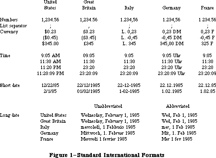 Figure 1–Standard International Formats
_______________________________________________________________________________
»International Resource 0
The International Utilities Package contains the following data types for accessing international resource 0:
TYPE Intl0Hndl = ^Intl0Ptr;
Intl0Ptr = ^Intl0Rec;
Intl0Rec = PACKED RECORD
decimalPt: CHAR; {decimal point character}
thousSep: CHAR; {thousands separator}
listSep: CHAR; {list separator}
currSym1: CHAR; {currency symbol}
currSym2: CHAR;
currSym3: CHAR;
currFmt: Byte; {currency format}
dateOrder: Byte; {order of short date elements}
shrtDateFmt: Byte; {short date format}
dateSep: CHAR; {date separator}
timeCycle: Byte; {0 if 24-hour cycle, 255 if 12-hour}
timeFmt: Byte; {time format}
mornStr: PACKED ARRAY[1..4] OF CHAR;
{trailing string for first }
{ 12-hour cycle}
eveStr: PACKED ARRAY[1..4] OF CHAR;
{trailing string for last }
{ 12-hour cycle}
timeSep: CHAR; {time separator}
time1Suff: CHAR; {trailing string for 24-hour cycle}
time2Suff: CHAR;
time3Suff: CHAR;
time4Suff: CHAR;
time5Suff: CHAR;
time6Suff: CHAR;
time7Suff: CHAR;
time8Suff: CHAR;
metricSys: Byte; {255 if metric, 0 if not}
intl0Vers: INTEGER {version information}
END;
Note: A NUL character (ASCII code 0) in a field of type CHAR means there’s
no such character. The currency symbol and the trailing string for
the 24-hour cycle are separated into individual CHAR fields because
of Pascal packing conventions. All strings include any required spaces.
The decimalPt, thousSep, and listSep fields define the number format. The thousands separator is the character that separates every three digits to the left of the decimal point. The list separator is the character that separates numbers, as when a list of numbers is entered by the user; it must be different from the decimal point character. If it’s the same as the thousands separator, the user must not include the latter in entered numbers.
CurrSym1 through currSym3 define the currency symbol (only one character for the United States and Great Britain, but two for France and three for Italy and Germany). CurrFmt determines the rest of the currency format, as shown in Figure 2. The decimal point character and thousands separator for currency are the same as in the number format.
Figure 1–Standard International Formats
_______________________________________________________________________________
»International Resource 0
The International Utilities Package contains the following data types for accessing international resource 0:
TYPE Intl0Hndl = ^Intl0Ptr;
Intl0Ptr = ^Intl0Rec;
Intl0Rec = PACKED RECORD
decimalPt: CHAR; {decimal point character}
thousSep: CHAR; {thousands separator}
listSep: CHAR; {list separator}
currSym1: CHAR; {currency symbol}
currSym2: CHAR;
currSym3: CHAR;
currFmt: Byte; {currency format}
dateOrder: Byte; {order of short date elements}
shrtDateFmt: Byte; {short date format}
dateSep: CHAR; {date separator}
timeCycle: Byte; {0 if 24-hour cycle, 255 if 12-hour}
timeFmt: Byte; {time format}
mornStr: PACKED ARRAY[1..4] OF CHAR;
{trailing string for first }
{ 12-hour cycle}
eveStr: PACKED ARRAY[1..4] OF CHAR;
{trailing string for last }
{ 12-hour cycle}
timeSep: CHAR; {time separator}
time1Suff: CHAR; {trailing string for 24-hour cycle}
time2Suff: CHAR;
time3Suff: CHAR;
time4Suff: CHAR;
time5Suff: CHAR;
time6Suff: CHAR;
time7Suff: CHAR;
time8Suff: CHAR;
metricSys: Byte; {255 if metric, 0 if not}
intl0Vers: INTEGER {version information}
END;
Note: A NUL character (ASCII code 0) in a field of type CHAR means there’s
no such character. The currency symbol and the trailing string for
the 24-hour cycle are separated into individual CHAR fields because
of Pascal packing conventions. All strings include any required spaces.
The decimalPt, thousSep, and listSep fields define the number format. The thousands separator is the character that separates every three digits to the left of the decimal point. The list separator is the character that separates numbers, as when a list of numbers is entered by the user; it must be different from the decimal point character. If it’s the same as the thousands separator, the user must not include the latter in entered numbers.
CurrSym1 through currSym3 define the currency symbol (only one character for the United States and Great Britain, but two for France and three for Italy and Germany). CurrFmt determines the rest of the currency format, as shown in Figure 2. The decimal point character and thousands separator for currency are the same as in the number format.
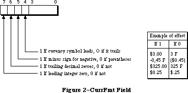 Figure 2–CurrFmt Field
The following predefined constants are masks that can be used to set or test the bits in the currFmt field:
CONST currSymLead = 16; {set if currency symbol leads}
currNegSym = 32; {set if minus sign for negative}
currTrailingZ = 64; {set if trailing decimal zeroes}
currLeadingZ = 128; {set if leading integer zero}
Note: You can also apply the currency format’s leading- and
trailing-zero indicators to the number format if desired.
The dateOrder, shrtDateFmt, and dateSep fields define the short date format. DateOrder indicates the order of the day, month, and year, with one of the following values:
CONST mdy = 0; {month day year}
dmy = 1; {day month year}
ymd = 2; {year month day}
ShrtDateFmt determines whether to show leading zeroes in day and month numbers and whether to show the century, as illustrated in Figure 3. DateSep is the character that separates the different parts of the date.
Figure 2–CurrFmt Field
The following predefined constants are masks that can be used to set or test the bits in the currFmt field:
CONST currSymLead = 16; {set if currency symbol leads}
currNegSym = 32; {set if minus sign for negative}
currTrailingZ = 64; {set if trailing decimal zeroes}
currLeadingZ = 128; {set if leading integer zero}
Note: You can also apply the currency format’s leading- and
trailing-zero indicators to the number format if desired.
The dateOrder, shrtDateFmt, and dateSep fields define the short date format. DateOrder indicates the order of the day, month, and year, with one of the following values:
CONST mdy = 0; {month day year}
dmy = 1; {day month year}
ymd = 2; {year month day}
ShrtDateFmt determines whether to show leading zeroes in day and month numbers and whether to show the century, as illustrated in Figure 3. DateSep is the character that separates the different parts of the date.
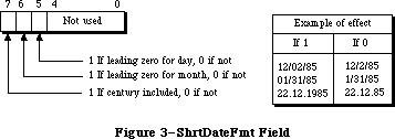 Figure 3–ShrtDateFmt Field
To set or test the bits in the shrtDateFmt field, you can use the following predefined constants as masks:
CONST dayLdingZ = 32; {set if leading zero for day}
mntLdingZ = 64; {set if leading zero for month}
century = 128; {set if century included}
The next several fields define the time format: the cycle (12 or 24 hours); whether to show leading zeroes (timeFmt, as shown in Figure 4); a string to follow the time (two for 12-hour cycle, one for 24-hour); and the time separator character.
Figure 3–ShrtDateFmt Field
To set or test the bits in the shrtDateFmt field, you can use the following predefined constants as masks:
CONST dayLdingZ = 32; {set if leading zero for day}
mntLdingZ = 64; {set if leading zero for month}
century = 128; {set if century included}
The next several fields define the time format: the cycle (12 or 24 hours); whether to show leading zeroes (timeFmt, as shown in Figure 4); a string to follow the time (two for 12-hour cycle, one for 24-hour); and the time separator character.
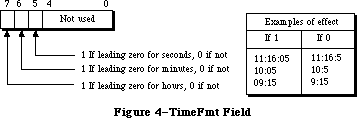 Figure 4–TimeFmt Field
The following masks are available for setting or testing bits in the timeFmt field:
CONST secLeadingZ = 32; {set if leading zero for seconds}
minLeadingZ = 64; {set if leading zero for minutes}
hrLeadingZ = 128; {set it leading zero for hours}
MetricSys indicates whether to use the metric system. The last field, intl0Vers, contains a version number in its low-order byte and one of the following constants in its high-order byte:
CONST verUS = 0;
verFrance = 1;
verBritain = 2;
verGermany = 3;
verItaly = 4;
verNetherlands = 5;
verBelgiumLux = 6;
verSweden = 7;
verSpain = 8;
verDenmark = 9;
verPortugal = 10;
verFrCanada = 11;
verNorway = 12;
verIsrael = 13;
verJapan = 14;
verAustralia = 15;
verArabia = 16;
verFinland = 17;
verFrSwiss = 18;
verGrSwiss = 19;
verGreece = 20;
verIceland = 21;
verMalta = 22;
verCyprus = 23;
verTurkey = 24;
verYugoslavia = 25;
_______________________________________________________________________________
»International Resource 1
The International Utilities Package contains the following data types for accessing international resource 1:
TYPE Intl1Hndl = ^Intl1Ptr;
Intl1Ptr = ^Intl1Rec;
Intl1Rec = PACKED RECORD
days: ARRAY[1..7] OF STRING[15]; {day names}
months: ARRAY[1..12] OF STRING[15]; {month names}
suppressDay: Byte; {0 for day name, 255 for none}
lngDateFmt: Byte; {order of long date elements}
dayLeading0: Byte; {255 for leading 0 in day number}
abbrLen: Byte; {length for abbreviating names}
st0: PACKED ARRAY[1..4] OF CHAR; {strings }
st1: PACKED ARRAY[1..4] OF CHAR; { for }
st2: PACKED ARRAY[1..4] OF CHAR; { long }
st3: PACKED ARRAY[1..4] OF CHAR; { date }
st4: PACKED ARRAY[1..4] OF CHAR; { format}
intl1Vers: INTEGER; {version information}
localRtn: INTEGER {routine for localizing string }
{ comparison; actually may be }
{ longer than one integer}
END;
All fields except the last two determine the long date format. The day names in the days array are ordered from Sunday to Saturday. (The month names are of course ordered from January to December.) As shown below, the lngDateFmt field determines the order of the various parts of the date. St0 through st4 are strings (usually punctuation) that appear in the date.
lngDateFmt Long date format
0 st0 day name st1 day st2 month st3 year st4
255 st0 day name st1 month st2 day st3 year st4
See Figure 5 for examples of how the International Utilities Package formats dates based on these fields. The examples assume that the suppressDay and dayLeading0 fields contain 0. A suppressDay value of 255 causes the day name and st1 to be omitted, and a dayLeading value of 255 causes a 0 to appear before day numbers less than 10.
Figure 4–TimeFmt Field
The following masks are available for setting or testing bits in the timeFmt field:
CONST secLeadingZ = 32; {set if leading zero for seconds}
minLeadingZ = 64; {set if leading zero for minutes}
hrLeadingZ = 128; {set it leading zero for hours}
MetricSys indicates whether to use the metric system. The last field, intl0Vers, contains a version number in its low-order byte and one of the following constants in its high-order byte:
CONST verUS = 0;
verFrance = 1;
verBritain = 2;
verGermany = 3;
verItaly = 4;
verNetherlands = 5;
verBelgiumLux = 6;
verSweden = 7;
verSpain = 8;
verDenmark = 9;
verPortugal = 10;
verFrCanada = 11;
verNorway = 12;
verIsrael = 13;
verJapan = 14;
verAustralia = 15;
verArabia = 16;
verFinland = 17;
verFrSwiss = 18;
verGrSwiss = 19;
verGreece = 20;
verIceland = 21;
verMalta = 22;
verCyprus = 23;
verTurkey = 24;
verYugoslavia = 25;
_______________________________________________________________________________
»International Resource 1
The International Utilities Package contains the following data types for accessing international resource 1:
TYPE Intl1Hndl = ^Intl1Ptr;
Intl1Ptr = ^Intl1Rec;
Intl1Rec = PACKED RECORD
days: ARRAY[1..7] OF STRING[15]; {day names}
months: ARRAY[1..12] OF STRING[15]; {month names}
suppressDay: Byte; {0 for day name, 255 for none}
lngDateFmt: Byte; {order of long date elements}
dayLeading0: Byte; {255 for leading 0 in day number}
abbrLen: Byte; {length for abbreviating names}
st0: PACKED ARRAY[1..4] OF CHAR; {strings }
st1: PACKED ARRAY[1..4] OF CHAR; { for }
st2: PACKED ARRAY[1..4] OF CHAR; { long }
st3: PACKED ARRAY[1..4] OF CHAR; { date }
st4: PACKED ARRAY[1..4] OF CHAR; { format}
intl1Vers: INTEGER; {version information}
localRtn: INTEGER {routine for localizing string }
{ comparison; actually may be }
{ longer than one integer}
END;
All fields except the last two determine the long date format. The day names in the days array are ordered from Sunday to Saturday. (The month names are of course ordered from January to December.) As shown below, the lngDateFmt field determines the order of the various parts of the date. St0 through st4 are strings (usually punctuation) that appear in the date.
lngDateFmt Long date format
0 st0 day name st1 day st2 month st3 year st4
255 st0 day name st1 month st2 day st3 year st4
See Figure 5 for examples of how the International Utilities Package formats dates based on these fields. The examples assume that the suppressDay and dayLeading0 fields contain 0. A suppressDay value of 255 causes the day name and st1 to be omitted, and a dayLeading value of 255 causes a 0 to appear before day numbers less than 10.
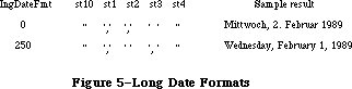 Figure 5–Long Date Formats
AbbrLen is the number of characters to which month and day names should be abbreviated when abbreviation is desired.
The intl1Vers field contains version information with the same format as the intl0Vers field of international resource 0.
LocalRtn contains a routine that localizes the built-in character ordering (as described below under “International String Comparison”).
_______________________________________________________________________________
»CHANGES TO THE INTERNATIONAL RESOURCES
_______________________________________________________________________________
Note: The extensions to the International Utilities Package described in this
section were originally documented in Inside Macintosh, Volume V. As
such, this information refers to the Macintosh SE and Macintosh II ROMs
and System file version 4.1 and later.
The 'INTL' resources with ID numbers 0 and 1 have been used in the past for international formats. The Script Manager now allows multiple formats to be used with the same system by adding multiple international script resources, as described in the Script Manager chapter. The new international resources are of types 'itl0', 'itl1', 'itl2', 'itlb', and 'itlc'. Each installed script has an associated list of international resource numbers, generally in the range used for its fonts. For example, the Arabic script has the resources 'itl0',
'itl1', and 'itl2' with numbers in the range $4600 to $47FF; the Roman script has the resources 'itl0', 'itl1', and 'itl2' with numbers in the range $2 to $3FFF.
In the default case, the resources used by the International Utilities package are determined by the script designated for the system font. However, you can force them to be determined by the font script (the script of the font in thePort), by clearing the IntlForce flag to 0. You can set and clear the IntlForce flag by using the SetEnvirons routine described in the Script Manager chapter. The selected resources will then be used internally by the International Utilities package.
The 'itl0' and 'itl1' resources basically correspond to the former 'INTL' 0 and 1; the 'itl2' resource contains new procedures for sorting, which are discussed below. The IUSetIntl call still uses the 'INTL' 0 and 1 resources. IUGetIntl, however, uses the 'itl0', 'itl1' and 'itl2' resources.
For compatibility, the 'INTL' 0 and 1 resources are still present in the System file and remain the same; an 'INTL' 2 has been added to correspond to the
'itl2'. Applications can access these resources by means of GetResource.
Note: The one exception to the correspondence between an 'itl0' or 'itl1'
and 'INTL' 0 or 'INTL' 1 is that the lengths of the former may be
increased at some future date: they are not guaranteed to remain
the same length, although the positions of the existing fields will
not change.
The 'itlb' resource is a script bundle resource that determines which keyboard and which international formats are to be used. The 'itlc' resource determines the system script.
_______________________________________________________________________________
»New Formatting Options
New options are available for time cycle and dates.
»Time Cycle
A new constant value, zeroCycle, is provided for the timeCycle field in the Intl0Rec data structure to allow specification of 0:00 am/pm rather than 12:00 or 24:00.
»Short Date Format
Three new constant values, MYD, DYM, YDM, for the dateOrder field in the Intl0Rec data structure now allow the exact specification of the short date format, as follows:
Constant Format
MYD Month Year Day
DYM Day Year Month
YDM Year Day Month
»Long Date Format
New values allow specification of the exact order of the elements in the long date format. If the byte value of the lngDateFmt field in the Intl1Rec data structure is neither 0 nor $FF, then its value is divided into four fields of two bits each. The least significant bit field (bits 0 and 1) corresponds to the first element in the long date format, while the most significant bit field (bits 6 and 7) specifies the last (fourth) element in the format. Four new constants (longDay, longWeek, longMonth, longYear) may be used to set each bit field to the appropriate value.
For example, to specify the order day-of-week/day-of-month/month/year, you would set the value of lngDateFmt to:
longWeek*1 {sets bits 0 and 1 to longWeek}
+ longDay*4 {sets bits 2 and 3 to longDay}
+ longMonth*16 {sets bits 4 and 5 to longMonth}
+ longYear*64 {sets bits 6 and 7 to longYear}
»Suppress Day
New values are available for the suppressDay field in the Intl1Rec data structure to enable suppression of any part of the date. If its value does not equal 0 or $FF, the field is treated as a bitmap. The values supDay, supWeek, supMonth and supYear may be used to set the appropriate bits in the suppressDay byte. For example, to suppress both the month and the year, the value of suppressDay would be: supMonth + supYear.
_______________________________________________________________________________
»Using the International Resources
Note: Before using any of the international resources, or using the Binary
to Decimal routines, verify that the thePort and thePort^.txFont are
set correctly, or that the intlForce flag is on.
To make it easy to localize your application to different scripts and languages, use the international utilities for Date/Time/Number formatting. When formatting numbers, use the fields in the international resources to find out the decimal, thousands or list separators for the given script.
{Make sure the font is set properly in thePort, then}
myHandle := intl0Hndl(IUGetIntl(0)); {don't use GetResource!}
myDecimal := myHandle^^.decimalPt; {as in 1.234 in English}
myThousands := myHandle^^.thousSep; {as in 1,234,567 in English}
myList := myHandle^^.listSep; {as in (3;4;5) in English}
These three separators should always be distinct; they can be used for parsing. Programs that do not support input of numbers with thousands separators may want to override the list separator and use commas. The program should keep any overriding characters in a resource, so they can be changed if necessary. Before using the resource, it should first check to see that the decimal separator is not the same.
When sorting a list of text items having different scripts, first sort the items by script, producing sublists. Then within each sublist sort the text items, using the International Utilities comparison routine described later in this chapter, with the intlForce off and the font in thePort set to one of the fonts in the sublist.
Where performance is critical, such as when you are sorting very large amounts of data in memory, it may be advantageous to use a straight ASCII comparison instead of the International Utilities comparison routines. In this case, give the user a choice of sorting style (quick versus accurate) in a preferences dialog. The stored default setting can be determined when localizing the application.
_______________________________________________________________________________
»INTERNATIONAL STRING COMPARISON
_______________________________________________________________________________
The International Utilities Package lets you compare strings in a way that accounts for diacritical marks and other special characters. The sort order built into the package may be localized through a routine stored in international resource 1.
The sort order is determined by a ranking of the entire Macintosh character set. The ranking can be thought of as a two-dimensional table. Each row of the table is a class of characters such as all A’s (uppercase and lowercase, with and without diacritical marks). The characters are ordered within each row, but this ordering is secondary to the order of the rows themselves. For example, given that the rows for letters are ordered alphabetically, the following are all true under this scheme:
'A' < 'a'
and 'Ab' < 'ab'
but 'Ac' > 'ab'
Even though 'A' < 'a' within the A row, 'Ac' > 'ab' because the order 'c' > 'b' takes precedence over the secondary ordering of the 'a' and the 'A'. In effect, the secondary ordering is ignored unless the comparison based on the primary ordering yields equality.
Note: The Pascal relational operators are used here for convenience only.
String comparison in Pascal yields very different results, since it
simply follows the ordering of the characters’ ASCII codes.
When the strings being compared are of different lengths, each character in the longer string that doesn’t correspond to a character in the shorter one compares “greater”; thus 'a' < 'ab'. This takes precedence over secondary ordering, so 'a' < 'Ab' even though 'A' < 'a'.
Besides letting you compare strings as described above, the International Utilities Package includes a routine that compares strings for equality without regard for secondary ordering. The effect on comparing letters, for example, is that diacritical marks are ignored and uppercase and lowercase are not distinguished.
Figure 6 shows the two-dimensional ordering of the character set (from least to greatest as you read from top to bottom or left to right). The numbers on the left are ASCII codes corresponding to each row; ellipses (...) designate sequences of rows of just one character. Some codes do not correspond to rows
(such as $61 through $7A, because lowercase letters are included in with their uppercase equivalents). See the Toolbox Event Manager for a table showing all the characters and their ASCII codes.
Characters combining two letters, as in the $AE row, are called ligatures. As shown in Figure 7, they’re actually expanded to the corresponding two letters, in the following sense:
• Primary ordering: The ligature is equal to the two-character sequence.
• Secondary ordering: The ligature is greater than the two-character
sequence.
Figure 5–Long Date Formats
AbbrLen is the number of characters to which month and day names should be abbreviated when abbreviation is desired.
The intl1Vers field contains version information with the same format as the intl0Vers field of international resource 0.
LocalRtn contains a routine that localizes the built-in character ordering (as described below under “International String Comparison”).
_______________________________________________________________________________
»CHANGES TO THE INTERNATIONAL RESOURCES
_______________________________________________________________________________
Note: The extensions to the International Utilities Package described in this
section were originally documented in Inside Macintosh, Volume V. As
such, this information refers to the Macintosh SE and Macintosh II ROMs
and System file version 4.1 and later.
The 'INTL' resources with ID numbers 0 and 1 have been used in the past for international formats. The Script Manager now allows multiple formats to be used with the same system by adding multiple international script resources, as described in the Script Manager chapter. The new international resources are of types 'itl0', 'itl1', 'itl2', 'itlb', and 'itlc'. Each installed script has an associated list of international resource numbers, generally in the range used for its fonts. For example, the Arabic script has the resources 'itl0',
'itl1', and 'itl2' with numbers in the range $4600 to $47FF; the Roman script has the resources 'itl0', 'itl1', and 'itl2' with numbers in the range $2 to $3FFF.
In the default case, the resources used by the International Utilities package are determined by the script designated for the system font. However, you can force them to be determined by the font script (the script of the font in thePort), by clearing the IntlForce flag to 0. You can set and clear the IntlForce flag by using the SetEnvirons routine described in the Script Manager chapter. The selected resources will then be used internally by the International Utilities package.
The 'itl0' and 'itl1' resources basically correspond to the former 'INTL' 0 and 1; the 'itl2' resource contains new procedures for sorting, which are discussed below. The IUSetIntl call still uses the 'INTL' 0 and 1 resources. IUGetIntl, however, uses the 'itl0', 'itl1' and 'itl2' resources.
For compatibility, the 'INTL' 0 and 1 resources are still present in the System file and remain the same; an 'INTL' 2 has been added to correspond to the
'itl2'. Applications can access these resources by means of GetResource.
Note: The one exception to the correspondence between an 'itl0' or 'itl1'
and 'INTL' 0 or 'INTL' 1 is that the lengths of the former may be
increased at some future date: they are not guaranteed to remain
the same length, although the positions of the existing fields will
not change.
The 'itlb' resource is a script bundle resource that determines which keyboard and which international formats are to be used. The 'itlc' resource determines the system script.
_______________________________________________________________________________
»New Formatting Options
New options are available for time cycle and dates.
»Time Cycle
A new constant value, zeroCycle, is provided for the timeCycle field in the Intl0Rec data structure to allow specification of 0:00 am/pm rather than 12:00 or 24:00.
»Short Date Format
Three new constant values, MYD, DYM, YDM, for the dateOrder field in the Intl0Rec data structure now allow the exact specification of the short date format, as follows:
Constant Format
MYD Month Year Day
DYM Day Year Month
YDM Year Day Month
»Long Date Format
New values allow specification of the exact order of the elements in the long date format. If the byte value of the lngDateFmt field in the Intl1Rec data structure is neither 0 nor $FF, then its value is divided into four fields of two bits each. The least significant bit field (bits 0 and 1) corresponds to the first element in the long date format, while the most significant bit field (bits 6 and 7) specifies the last (fourth) element in the format. Four new constants (longDay, longWeek, longMonth, longYear) may be used to set each bit field to the appropriate value.
For example, to specify the order day-of-week/day-of-month/month/year, you would set the value of lngDateFmt to:
longWeek*1 {sets bits 0 and 1 to longWeek}
+ longDay*4 {sets bits 2 and 3 to longDay}
+ longMonth*16 {sets bits 4 and 5 to longMonth}
+ longYear*64 {sets bits 6 and 7 to longYear}
»Suppress Day
New values are available for the suppressDay field in the Intl1Rec data structure to enable suppression of any part of the date. If its value does not equal 0 or $FF, the field is treated as a bitmap. The values supDay, supWeek, supMonth and supYear may be used to set the appropriate bits in the suppressDay byte. For example, to suppress both the month and the year, the value of suppressDay would be: supMonth + supYear.
_______________________________________________________________________________
»Using the International Resources
Note: Before using any of the international resources, or using the Binary
to Decimal routines, verify that the thePort and thePort^.txFont are
set correctly, or that the intlForce flag is on.
To make it easy to localize your application to different scripts and languages, use the international utilities for Date/Time/Number formatting. When formatting numbers, use the fields in the international resources to find out the decimal, thousands or list separators for the given script.
{Make sure the font is set properly in thePort, then}
myHandle := intl0Hndl(IUGetIntl(0)); {don't use GetResource!}
myDecimal := myHandle^^.decimalPt; {as in 1.234 in English}
myThousands := myHandle^^.thousSep; {as in 1,234,567 in English}
myList := myHandle^^.listSep; {as in (3;4;5) in English}
These three separators should always be distinct; they can be used for parsing. Programs that do not support input of numbers with thousands separators may want to override the list separator and use commas. The program should keep any overriding characters in a resource, so they can be changed if necessary. Before using the resource, it should first check to see that the decimal separator is not the same.
When sorting a list of text items having different scripts, first sort the items by script, producing sublists. Then within each sublist sort the text items, using the International Utilities comparison routine described later in this chapter, with the intlForce off and the font in thePort set to one of the fonts in the sublist.
Where performance is critical, such as when you are sorting very large amounts of data in memory, it may be advantageous to use a straight ASCII comparison instead of the International Utilities comparison routines. In this case, give the user a choice of sorting style (quick versus accurate) in a preferences dialog. The stored default setting can be determined when localizing the application.
_______________________________________________________________________________
»INTERNATIONAL STRING COMPARISON
_______________________________________________________________________________
The International Utilities Package lets you compare strings in a way that accounts for diacritical marks and other special characters. The sort order built into the package may be localized through a routine stored in international resource 1.
The sort order is determined by a ranking of the entire Macintosh character set. The ranking can be thought of as a two-dimensional table. Each row of the table is a class of characters such as all A’s (uppercase and lowercase, with and without diacritical marks). The characters are ordered within each row, but this ordering is secondary to the order of the rows themselves. For example, given that the rows for letters are ordered alphabetically, the following are all true under this scheme:
'A' < 'a'
and 'Ab' < 'ab'
but 'Ac' > 'ab'
Even though 'A' < 'a' within the A row, 'Ac' > 'ab' because the order 'c' > 'b' takes precedence over the secondary ordering of the 'a' and the 'A'. In effect, the secondary ordering is ignored unless the comparison based on the primary ordering yields equality.
Note: The Pascal relational operators are used here for convenience only.
String comparison in Pascal yields very different results, since it
simply follows the ordering of the characters’ ASCII codes.
When the strings being compared are of different lengths, each character in the longer string that doesn’t correspond to a character in the shorter one compares “greater”; thus 'a' < 'ab'. This takes precedence over secondary ordering, so 'a' < 'Ab' even though 'A' < 'a'.
Besides letting you compare strings as described above, the International Utilities Package includes a routine that compares strings for equality without regard for secondary ordering. The effect on comparing letters, for example, is that diacritical marks are ignored and uppercase and lowercase are not distinguished.
Figure 6 shows the two-dimensional ordering of the character set (from least to greatest as you read from top to bottom or left to right). The numbers on the left are ASCII codes corresponding to each row; ellipses (...) designate sequences of rows of just one character. Some codes do not correspond to rows
(such as $61 through $7A, because lowercase letters are included in with their uppercase equivalents). See the Toolbox Event Manager for a table showing all the characters and their ASCII codes.
Characters combining two letters, as in the $AE row, are called ligatures. As shown in Figure 7, they’re actually expanded to the corresponding two letters, in the following sense:
• Primary ordering: The ligature is equal to the two-character sequence.
• Secondary ordering: The ligature is greater than the two-character
sequence.
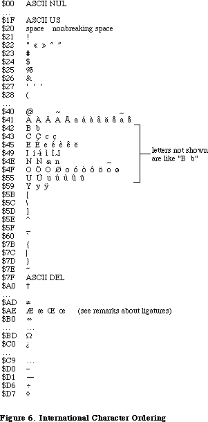 Figure 6–International Character Ordering
Ligatures are ordered somewhat differently in Germany to accommodate umlauted characters (see Figure 7). This is accomplished by means of the routine in international resource 1 for localizing the built-in character ordering. In the system resource file for Germany, this routine expands umlauted characters to the corresponding two letters (for example, “AE” for A-umlaut). The secondary ordering places the umlauted character between the two-character sequence and the ligature, if any. Likewise, the German double-s character expands to “ss”.
Figure 6–International Character Ordering
Ligatures are ordered somewhat differently in Germany to accommodate umlauted characters (see Figure 7). This is accomplished by means of the routine in international resource 1 for localizing the built-in character ordering. In the system resource file for Germany, this routine expands umlauted characters to the corresponding two letters (for example, “AE” for A-umlaut). The secondary ordering places the umlauted character between the two-character sequence and the ligature, if any. Likewise, the German double-s character expands to “ss”.
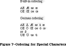 Figure 7–Ordering for Special Characters
In the system resource file for Great Britain, the localization routine in international resource 1 orders the pound currency sign between double quote and the pound weight sign (see Figure 8). For the United States, France, and Italy, the localization routine does nothing.
Figure 7–Ordering for Special Characters
In the system resource file for Great Britain, the localization routine in international resource 1 orders the pound currency sign between double quote and the pound weight sign (see Figure 8). For the United States, France, and Italy, the localization routine does nothing.
 Figure 8–Special Ordering for Great Britain
Assembly-language note: The null localization routine consists of an
RTS instruction.
_______________________________________________________________________________
»SORTING ROUTINES
_______________________________________________________________________________
Note: The extensions to the International Utilities Package described in this
section were originally documented in Inside Macintosh, Volume V. As
such, this information refers to the Macintosh SE and Macintosh II ROMs
and System file version 4.1 and later.
X-Ref: Technical Note #178
The international sorting routines handle cases where letters are equal in primary ordering but different in secondary ordering (e.g., ‘ä’ and ‘a’).
They also handle cases where one character sorts as if it were two (e.g., ‘æ’ as ‘ae’). The 'itl2' resource has been added to generalize the sorting process for non-Roman scripts.
This is the process that the International Utilities Package now uses to compare two strings:
• Starting with the first character, it fetches corresponding
characters from the two strings and compares them.
• If the characters are identical, the comparison continues.
• If the characters are not identical, and if one or both is part of a
secondary ordering (e.g., ‘ä’ and ‘a’), their primary characters are
compared.
• If the characters are not identical but their primary characters are
equal, the comparison continues.
• If neither the original characters nor their primary characters are
equal, the comparison ends and the ordering of the original characters
is returned.
• If the foregoing comparison continues and one string ends before the
other, then the shorter string is less.
• If the comparison continues to the end of strings that are the same
length and if the strings contain no characters that are equal in
primary ordering but different in secondary ordering, then the strings
are identical.
• If the comparison continues to the end of strings that are the same
length and contain one or more characters that are equal in primary
ordering but different in secondary ordering, then the first such pair
of characters is compared by secondary ordering to determine the final
ordering.
Note: It is possible to create your own ordering routine, using hook
routines contained in the 'itl2' resource. For guidance on doing
this, contact Developer Technical Support.
_______________________________________________________________________________
»USING THE INTERNATIONAL UTILITIES PACKAGE
_______________________________________________________________________________
The International Utilities Package is automatically read into memory from the system resource file when one of its routines is called. When a routine needs to access an international resource, it asks the Resource Manager to read the resource into memory. Together, the package and its resources occupy about 2K bytes.
As described in the Operating System Utilities chapter, you can get the date and time as a long integer from the GetDateTime procedure. If you need a string corresponding to the date or time, you can pass this long integer to the IUDateString or IUTimeString procedure in the International Utilities Package. These procedures determine the local format from the international resources read into memory by the Resource Manager (that is, resource type 'INTL' and resource ID 0 or 1). In some situations, you may need the format information to come instead from an international resource that you specify by its handle; if so, you can use IUDatePString or IUTimePString. This is useful, for example, if you want to use an international resource in a document’s resource file after you’ve closed that file.
Applications that use measurements, such as on a ruler for setting margins and tabs, can call IUMetric to find out whether to use the metric system. This function simply returns the value of the corresponding field in international resource 0. To access any other fields in an international resource—say, the currency format in international resource 0—call IUGetIntl to get a handle to the resource. If you change any of the fields and want to write the changed resource to a resource file, the IUSetIntl procedure lets you do this.
To sort strings, you can use IUCompString or, if you’re not dealing with Pascal strings, the more general IUMagString. These routines compare two strings and give their exact relationship, whether equal, less than, or greater than. Subtleties like diacritical marks and case differences are taken into consideration, as described above under “International String Comparison”. If you need to know only whether two strings are equal, and want to ignore the subtleties, use IUEqualString (or the more general IUMagIDString) instead.
Note: The Operating System Utility function EqualString also compares two
Pascal strings for equality. It’s less sophisticated than IUEqualString
in that it follows ASCII order more strictly; for details, see the
Operating System Utilities chapter.
_______________________________________________________________________________
»INTERNATIONAL UTILITIES PACKAGE ROUTINES
_______________________________________________________________________________
Assembly-language note: The trap macro for the International Utilities
Package is _Pack6. The routine selectors are as
follows:
iuDateString .EQU 0
iuTimeString .EQU 2
iuMetric .EQU 4
iuGetIntl .EQU 6
iuSetIntl .EQU 8
iuMagString .EQU 10
iuMagIDString .EQU 12
iuDatePString .EQU 14
iuTimePString .EQU 16
PROCEDURE IUDateString (dateTime: LONGINT; form: DateForm;
VAR result: Str255);
Given a date and time as returned by the Operating System Utility procedure GetDateTime, IUDateString returns in the result parameter a string that represents the corresponding date. The form parameter has the following data type:
TYPE DateForm = (shortDate,longDate,abbrevDate);
ShortDate requests the short date format, longDate the long date, and abbrevDate the abbreviated long date. IUDateString determines the exact format from international resource 0 for the short date or 1 for the long date. See Figure 1 for examples of the standard formats.
If the abbreviated long date is requested and the abbreviation length in international resource 1 is greater than the actual length of the name being abbreviated, IUDateString fills the abbreviation with NUL characters (ASCII code 0); the abbreviation length should not be greater than 15, the maximum name length.
PROCEDURE IUDatePString (dateTime: LONGINT; form: DateForm;
VAR result: Str255; intlParam: Handle);
IUDatePString is the same as IUDateString except that it determines the exact format of the date from the resource whose handle is passed in intlParam, overriding the resource that would otherwise be used.
PROCEDURE IUTimeString (dateTime: LONGINT; wantSeconds: BOOLEAN;
VAR result: Str255);
Given a date and time as returned by the Operating System Utility procedure GetDateTime, IUTimeString returns in the result parameter a string that represents the corresponding time of day. If wantSeconds is TRUE, seconds are included in the time; otherwise, only the hour and minute are included. IUTimeString determines the time format from international resource 0. See Figure 1 for examples of the standard formats.
PROCEDURE IUTimePString (dateTime: LONGINT; wantSeconds: BOOLEAN;
VAR result: Str255; intlParam: Handle);
IUTimePString is the same as IUTimeString except that it determines the time format from the resource whose handle is passed in intlParam, overriding the resource that would otherwise be used.
FUNCTION IUMetric : BOOLEAN;
If international resource 0 specifies that the metric system is to be used, IUMetric returns TRUE; otherwise, it returns FALSE.
FUNCTION IUGetIntl (theID: INTEGER) : Handle;
IUGetIntl returns a handle to the international resource numbered theID (0 or
1). It calls the Resource Manager function GetResource('INTL',theID). For example, if you want to access individual fields of international resource 0, you can do the following:
VAR myHndl: Handle;
int0: Intl0Hndl;
. . .
myHndl := IUGetIntl(0);
int0 := Intl0Hndl(myHndl)
PROCEDURE IUSetIntl (refNum: INTEGER; theID: INTEGER; intlParam: Handle);
In the resource file having the reference number refNum, IUSetIntl sets the international resource numbered theID (0 or 1) to the data specified by intlParam. The data may be either an existing resource or data that hasn’t yet been written to a resource file. IUSetIntl adds the resource to the specified file or replaces the resource if it’s already there.
FUNCTION IUCompString (aStr,bStr: Str255) : INTEGER; [Not in ROM]
IUCompString compares aStr and bStr as described above under “International String Comparison”, taking both primary and secondary ordering into consideration. It returns one of the values listed below.
Example
Result Meaning aStr bStr
–1 aStr is less than bStr 'Ab' 'ab'
0 aStr equals bStr 'Ab' 'Ab'
1 aStr is greater than bStr 'Ac' 'ab'
Assembly-language note: IUCompString was created for the convenience
of Pascal programmers; there’s no trap for it.
It eventually calls IUMagString, which is what
you should use from assembly language.
FUNCTION IUMagString (aPtr,bPtr: Ptr; aLen,bLen: INTEGER) : INTEGER;
IUMagString is the same as IUCompString (above) except that instead of comparing two Pascal strings, it compares the string defined by aPtr and aLen to the string defined by bPtr and bLen. The pointer points to the first character of the string (any byte in memory, not necessarily word-aligned), and the length specifies the number of characters in the string.
FUNCTION IUEqualString (aStr,bStr: Str255) : INTEGER; [Not in ROM]
IUEqualString compares aStr and bStr for equality without regard for secondary ordering, as described above under “International String Comparison”. If the strings are equal, it returns 0; otherwise, it returns 1. For example, if the strings are 'Rose' and 'rose', IUEqualString considers them equal and returns 0.
Note: See also EqualString in the Operating System Utilities chapter.
Assembly-language note: IUEqualString was created for the convenience of
Pascal programmers; there’s no trap for it. It
eventually calls IUMagIDString, which is what you
should use from assembly language.
FUNCTION IUMagIDString (aPtr,bPtr: Ptr; aLen,bLen: INTEGER) : INTEGER;
IUMagIDString is the same as IUEqualString (above) except that instead of comparing two Pascal strings, it compares the string defined by aPtr and aLen to the string defined by bPtr and bLen. The pointer points to the first character of the string (any byte in memory, not necessarily word-aligned), and the length specifies the number of characters in the string.
_______________________________________________________________________________
»SUMMARY OF THE INTERNATIONAL UTILITIES PACKAGE
_______________________________________________________________________________
Constants
CONST
zeroCycle = 1; {0:00 AM/PM format [Volume V addition]}
{ Masks for currency format }
currSymLead = 16; {set if currency symbol leads}
currNegSym = 32; {set if minus sign for negative}
currTrailingZ = 64; {set if trailing decimal zeroes}
currLeadingZ = 128; {set if leading integer zero}
{ Order of short date elements }
mdy = 0; {month day year}
dmy = 1; {day month year}
ymd = 2; {year month day}
MYD = 3; {month, day, year [Volume V addition]}
DYM = 4; {day, year, month [Volume V addition]}
YDM = 5; {year, day, month [Volume V addition]}
{ Masks for short date format }
dayLdingZ = 32; {set if leading zero for day}
mntLdingZ = 64; {set if leading zero for month}
century = 128; {set if century included}
{ Order of long date elements }
longDay = 0; {day of the month [Volume V addition]}
longWeek = 1; {day of the week [Volume V addition]}
longMonth = 2; {month of the year [Volume V addition]}
longYear = 3; {year [Volume V addition]}
{ Suppression of date elements }
supDay = 1; {suppress day of month [Volume V addition]}
supWeek = 2; {suppress day of week [Volume V addition]}
supMonth = 4; {suppress month [Volume V addition]}
supYear = 8; {suppress year [Volume V addition]}
{ Masks for time format }
secLeadingZ = 32; {set if leading zero for seconds}
minLeadingZ = 64; {set if leading zero for minutes}
hrLeadingZ = 128; {set if leading zero for hours}
{ High-order byte of version information }
verUS = 0;
verFrance = 1;
verBritain = 2;
verGermany = 3;
verItaly = 4;
verNetherlands = 5;
verBelgiumLux = 6;
verSweden = 7;
verSpain = 8;
verDenmark = 9;
verPortugal = 10;
verFrCanada = 11;
verNorway = 12;
verIsrael = 13;
verJapan = 14;
verAustralia = 15;
verArabia = 16;
verFinland = 17;
verFrSwiss = 18;
verGrSwiss = 19;
verGreece = 20;
verIceland = 21;
verMalta = 22;
verCyprus = 23;
verTurkey = 24;
verYugoslavia = 25;
_______________________________________________________________________________
Data Types
TYPE
Intl0Hndl = ^Intl0Ptr;
Intl0Ptr = ^Intl0Rec;
Intl0Rec = PACKED RECORD
decimalPt: CHAR; {decimal point character}
thousSep: CHAR; {thousands separator}
listSep: CHAR; {list separator}
currSym1: CHAR; {currency symbol}
currSym2: CHAR;
currSym3: CHAR;
currFmt: Byte; {currency format}
dateOrder: Byte; {order of short date elements}
shrtDateFmt: Byte; {short date format}
dateSep: CHAR; {date separator}
timeCycle: Byte; {0 if 24-hour cycle, 255 if 12-hour}
timeFmt: Byte; {time format}
mornStr: PACKED ARRAY[1..4] OF CHAR;
{trailing string for first }
{ 12-hour cycle}
eveStr: PACKED ARRAY[1..4] OF CHAR;
{trailing string for last }
{ 12-hour cycle}
timeSep: CHAR; {time separator}
time1Suff: CHAR; {trailing string for 24-hour cycle}
time2Suff: CHAR;
time3Suff: CHAR;
time4Suff: CHAR;
time5Suff: CHAR;
time6Suff: CHAR;
time7Suff: CHAR;
time8Suff: CHAR;
metricSys: Byte; {255 if metric, 0 if not}
intl0Vers: INTEGER {version information}
END;
Intl1Hndl = ^Intl1Ptr;
Intl1Ptr = ^Intl1Rec;
Intl1Rec = PACKED RECORD
days: ARRAY[1..7] OF STRING[15]; {day names}
months: ARRAY[1..12] OF STRING[15]; {month names}
suppressDay: Byte; {0 for day name, 255 for none}
lngDateFmt: Byte; {order of long date elements}
dayLeading0: Byte; {255 for leading 0 in day number}
abbrLen: Byte; {length for abbreviating names}
st0: PACKED ARRAY[1..4] OF CHAR; {strings }
st1: PACKED ARRAY[1..4] OF CHAR; { for }
st2: PACKED ARRAY[1..4] OF CHAR; { long }
st3: PACKED ARRAY[1..4] OF CHAR; { date }
st4: PACKED ARRAY[1..4] OF CHAR; { format}
intl1Vers: INTEGER; {version information}
localRtn: INTEGER {routine for localizing string }
{ comparison; actually may be }
{ longer than one integer}
END;
DateForm = (shortDate,longDate,abbrevDate);
_______________________________________________________________________________
Routines
PROCEDURE IUDateString (dateTime: LONGINT; form: DateForm;
VAR result: Str255);
PROCEDURE IUDatePString (dateTime: LONGINT; form: DateForm;
VAR result: Str255; intlParam: Handle);
PROCEDURE IUTimeString (dateTime: LONGINT; wantSeconds: BOOLEAN;
VAR result: Str255);
PROCEDURE IUTimePString (dateTime: LONGINT; wantSeconds: (BOOLEAN;
VAR result: Str255;intlParam: Handle);
FUNCTION IUMetric : BOOLEAN;
FUNCTION IUGetIntl (theID: INTEGER) : Handle;
PROCEDURE IUSetIntl (refNum: INTEGER; theID: INTEGER;
intlParam: Handle);
FUNCTION IUCompString (aStr,bStr: Str255) : INTEGER; [Not in ROM]
FUNCTION IUMagString (aPtr,bPtr: Ptr; aLen,bLen: INTEGER) : INTEGER;
FUNCTION IUEqualString (aStr,bStr: Str255) : INTEGER; [Not in ROM]
FUNCTION IUMagIDString (aPtr,bPtr: Ptr; aLen,bLen: INTEGER) : INTEGER;
_______________________________________________________________________________
Assembly-Language Information
Constants
zeroCycle EQU 1 ;use 0:00 AM/PM format [Volume V addition]
; Masks for currency format
currSymLead .EQU 16 ;set if currency symbol leads
currNegSym .EQU 32 ;set if minus sign for negative
currTrailingZ .EQU 64 ;set if trailing decimal zeroes
currLeadingZ .EQU 128 ;set if leading integer zero
; Order of short date elements
mdy .EQU 0 ;month day year
dmy .EQU 1 ;day month year
ymd .EQU 2 ;year month day
MYD EQU 3 ;use month, year, day [Volume V addition]
DYM EQU 4 ;use day, year, month [Volume V addition]
YDM EQU 5 ;use year, day, month [Volume V addition]
; Masks for short date format
dayLdingZ .EQU 32 ;set if leading zero for day
mntLdingZ .EQU 64 ;set if leading zero for month
century .EQU 128 ;set if century included
; Order of long date elements
longDay EQU 0 ;day of month [Volume V addition]
longWeek EQU 1 ;day of week [Volume V addition]
longMonth EQU 2 ;month of year [Volume V addition]
longYear EQU 3 ;year [Volume V addition]
; Supression of date elements
supDay EQU 0 ;suppress day of month [Volume V addition]
supWeek EQU 2 ;suppress day of week [Volume V addition]
supMonth EQU 4 ;suppress month [Volume V addition]
supYear EQU 8 ;suppress year [Volume V addition]
; Masks for time format
secLeadingZ .EQU 32 ;set if leading zero for seconds
minLeadingZ .EQU 64 ;set if leading zero for minutes
hrLeadingZ .EQU 128 ;set if leading zero for hours
; High-order byte of version information
verUS .EQU 0
verFrance .EQU 1
verBritain .EQU 2
verGermany .EQU 3
verItaly .EQU 4
verNetherlands.EQU 5
verBelgiumLux .EQU 6
verSweden .EQU 7
verSpain .EQU 8
verDenmark .EQU 9
verPortugal .EQU 10
verFrCanada .EQU 11
verNorway .EQU 12
verIsrael .EQU 13
verJapan .EQU 14
verAustralia .EQU 15
verArabia .EQU 16
verFinland .EQU 17
verFrSwiss .EQU 18
verGrSwiss .EQU 19
verGreece .EQU 20
verIceland .EQU 21
verMalta .EQU 22
verCyprus .EQU 23
verTurkey .EQU 24
verYugoslavia .EQU 25
; Date form for IUDateString and IUDatePString
shortDate .EQU 0 ;short form of date
longDate .EQU 1 ;long form of date
abbrevDate .EQU 2 ;abbreviated long form
; Routine selectors
iuDateString .EQU 0
iuTimeString .EQU 2
iuMetric .EQU 4
iuGetIntl .EQU 6
iuSetIntl .EQU 8
iuMagString .EQU 10
iuMagIDString .EQU 12
iuDatePString .EQU 14
iuTimePString .EQU 16
International Resource 0 Data Structure
decimalPt Decimal point character (byte)
thousSep Thousands separator (byte)
listSep List separator (byte)
currSym Currency symbol (3 bytes)
currFmt Currency format (byte)
dateOrder Order of short date elements (byte)
shrtDateFmt Short date format (byte)
dateSep Date separator (byte)
timeCycle 0 if 24-hour cycle, 255 if 12-hour (byte)
timeFmt Time format (byte)
mornStr Trailing string for first 12-hour cycle (long)
eveStr Trailing string for last 12-hour cycle (long)
timeSep Time separator (byte)
timeSuff Trailing string for 24-hour cycle (8 bytes)
metricSys 255 if metric, 0 if not (byte)
intl0Vers Version information (word)
International Resource 1 Data Structure
days Day names (112 bytes)
months Month names (192 bytes)
suppressDay 0 for day name, 255 for none (byte)
lngDateFmt Order of long date elements (byte)
dayLeading0 255 for leading 0 in day number (byte)
abbrLen Length for abbreviating names (byte)
st0 Strings for long date format (longs)
st1
st2
st3
st4
intl1Vers Version information (word)
localRtn Comparison localization routine
Trap Macro Name
_Pack6
Further Reference:
_______________________________________________________________________________
Resource Manager
Package Manager
System Resource File
OS Utilities
Script Manager
Technical Note #153, Changes in International Utilities and Resources
Technical Note #178, Modifying the Standard String Comparison
Technical Note #242, Fonts and the Script Manager
Figure 8–Special Ordering for Great Britain
Assembly-language note: The null localization routine consists of an
RTS instruction.
_______________________________________________________________________________
»SORTING ROUTINES
_______________________________________________________________________________
Note: The extensions to the International Utilities Package described in this
section were originally documented in Inside Macintosh, Volume V. As
such, this information refers to the Macintosh SE and Macintosh II ROMs
and System file version 4.1 and later.
X-Ref: Technical Note #178
The international sorting routines handle cases where letters are equal in primary ordering but different in secondary ordering (e.g., ‘ä’ and ‘a’).
They also handle cases where one character sorts as if it were two (e.g., ‘æ’ as ‘ae’). The 'itl2' resource has been added to generalize the sorting process for non-Roman scripts.
This is the process that the International Utilities Package now uses to compare two strings:
• Starting with the first character, it fetches corresponding
characters from the two strings and compares them.
• If the characters are identical, the comparison continues.
• If the characters are not identical, and if one or both is part of a
secondary ordering (e.g., ‘ä’ and ‘a’), their primary characters are
compared.
• If the characters are not identical but their primary characters are
equal, the comparison continues.
• If neither the original characters nor their primary characters are
equal, the comparison ends and the ordering of the original characters
is returned.
• If the foregoing comparison continues and one string ends before the
other, then the shorter string is less.
• If the comparison continues to the end of strings that are the same
length and if the strings contain no characters that are equal in
primary ordering but different in secondary ordering, then the strings
are identical.
• If the comparison continues to the end of strings that are the same
length and contain one or more characters that are equal in primary
ordering but different in secondary ordering, then the first such pair
of characters is compared by secondary ordering to determine the final
ordering.
Note: It is possible to create your own ordering routine, using hook
routines contained in the 'itl2' resource. For guidance on doing
this, contact Developer Technical Support.
_______________________________________________________________________________
»USING THE INTERNATIONAL UTILITIES PACKAGE
_______________________________________________________________________________
The International Utilities Package is automatically read into memory from the system resource file when one of its routines is called. When a routine needs to access an international resource, it asks the Resource Manager to read the resource into memory. Together, the package and its resources occupy about 2K bytes.
As described in the Operating System Utilities chapter, you can get the date and time as a long integer from the GetDateTime procedure. If you need a string corresponding to the date or time, you can pass this long integer to the IUDateString or IUTimeString procedure in the International Utilities Package. These procedures determine the local format from the international resources read into memory by the Resource Manager (that is, resource type 'INTL' and resource ID 0 or 1). In some situations, you may need the format information to come instead from an international resource that you specify by its handle; if so, you can use IUDatePString or IUTimePString. This is useful, for example, if you want to use an international resource in a document’s resource file after you’ve closed that file.
Applications that use measurements, such as on a ruler for setting margins and tabs, can call IUMetric to find out whether to use the metric system. This function simply returns the value of the corresponding field in international resource 0. To access any other fields in an international resource—say, the currency format in international resource 0—call IUGetIntl to get a handle to the resource. If you change any of the fields and want to write the changed resource to a resource file, the IUSetIntl procedure lets you do this.
To sort strings, you can use IUCompString or, if you’re not dealing with Pascal strings, the more general IUMagString. These routines compare two strings and give their exact relationship, whether equal, less than, or greater than. Subtleties like diacritical marks and case differences are taken into consideration, as described above under “International String Comparison”. If you need to know only whether two strings are equal, and want to ignore the subtleties, use IUEqualString (or the more general IUMagIDString) instead.
Note: The Operating System Utility function EqualString also compares two
Pascal strings for equality. It’s less sophisticated than IUEqualString
in that it follows ASCII order more strictly; for details, see the
Operating System Utilities chapter.
_______________________________________________________________________________
»INTERNATIONAL UTILITIES PACKAGE ROUTINES
_______________________________________________________________________________
Assembly-language note: The trap macro for the International Utilities
Package is _Pack6. The routine selectors are as
follows:
iuDateString .EQU 0
iuTimeString .EQU 2
iuMetric .EQU 4
iuGetIntl .EQU 6
iuSetIntl .EQU 8
iuMagString .EQU 10
iuMagIDString .EQU 12
iuDatePString .EQU 14
iuTimePString .EQU 16
PROCEDURE IUDateString (dateTime: LONGINT; form: DateForm;
VAR result: Str255);
Given a date and time as returned by the Operating System Utility procedure GetDateTime, IUDateString returns in the result parameter a string that represents the corresponding date. The form parameter has the following data type:
TYPE DateForm = (shortDate,longDate,abbrevDate);
ShortDate requests the short date format, longDate the long date, and abbrevDate the abbreviated long date. IUDateString determines the exact format from international resource 0 for the short date or 1 for the long date. See Figure 1 for examples of the standard formats.
If the abbreviated long date is requested and the abbreviation length in international resource 1 is greater than the actual length of the name being abbreviated, IUDateString fills the abbreviation with NUL characters (ASCII code 0); the abbreviation length should not be greater than 15, the maximum name length.
PROCEDURE IUDatePString (dateTime: LONGINT; form: DateForm;
VAR result: Str255; intlParam: Handle);
IUDatePString is the same as IUDateString except that it determines the exact format of the date from the resource whose handle is passed in intlParam, overriding the resource that would otherwise be used.
PROCEDURE IUTimeString (dateTime: LONGINT; wantSeconds: BOOLEAN;
VAR result: Str255);
Given a date and time as returned by the Operating System Utility procedure GetDateTime, IUTimeString returns in the result parameter a string that represents the corresponding time of day. If wantSeconds is TRUE, seconds are included in the time; otherwise, only the hour and minute are included. IUTimeString determines the time format from international resource 0. See Figure 1 for examples of the standard formats.
PROCEDURE IUTimePString (dateTime: LONGINT; wantSeconds: BOOLEAN;
VAR result: Str255; intlParam: Handle);
IUTimePString is the same as IUTimeString except that it determines the time format from the resource whose handle is passed in intlParam, overriding the resource that would otherwise be used.
FUNCTION IUMetric : BOOLEAN;
If international resource 0 specifies that the metric system is to be used, IUMetric returns TRUE; otherwise, it returns FALSE.
FUNCTION IUGetIntl (theID: INTEGER) : Handle;
IUGetIntl returns a handle to the international resource numbered theID (0 or
1). It calls the Resource Manager function GetResource('INTL',theID). For example, if you want to access individual fields of international resource 0, you can do the following:
VAR myHndl: Handle;
int0: Intl0Hndl;
. . .
myHndl := IUGetIntl(0);
int0 := Intl0Hndl(myHndl)
PROCEDURE IUSetIntl (refNum: INTEGER; theID: INTEGER; intlParam: Handle);
In the resource file having the reference number refNum, IUSetIntl sets the international resource numbered theID (0 or 1) to the data specified by intlParam. The data may be either an existing resource or data that hasn’t yet been written to a resource file. IUSetIntl adds the resource to the specified file or replaces the resource if it’s already there.
FUNCTION IUCompString (aStr,bStr: Str255) : INTEGER; [Not in ROM]
IUCompString compares aStr and bStr as described above under “International String Comparison”, taking both primary and secondary ordering into consideration. It returns one of the values listed below.
Example
Result Meaning aStr bStr
–1 aStr is less than bStr 'Ab' 'ab'
0 aStr equals bStr 'Ab' 'Ab'
1 aStr is greater than bStr 'Ac' 'ab'
Assembly-language note: IUCompString was created for the convenience
of Pascal programmers; there’s no trap for it.
It eventually calls IUMagString, which is what
you should use from assembly language.
FUNCTION IUMagString (aPtr,bPtr: Ptr; aLen,bLen: INTEGER) : INTEGER;
IUMagString is the same as IUCompString (above) except that instead of comparing two Pascal strings, it compares the string defined by aPtr and aLen to the string defined by bPtr and bLen. The pointer points to the first character of the string (any byte in memory, not necessarily word-aligned), and the length specifies the number of characters in the string.
FUNCTION IUEqualString (aStr,bStr: Str255) : INTEGER; [Not in ROM]
IUEqualString compares aStr and bStr for equality without regard for secondary ordering, as described above under “International String Comparison”. If the strings are equal, it returns 0; otherwise, it returns 1. For example, if the strings are 'Rose' and 'rose', IUEqualString considers them equal and returns 0.
Note: See also EqualString in the Operating System Utilities chapter.
Assembly-language note: IUEqualString was created for the convenience of
Pascal programmers; there’s no trap for it. It
eventually calls IUMagIDString, which is what you
should use from assembly language.
FUNCTION IUMagIDString (aPtr,bPtr: Ptr; aLen,bLen: INTEGER) : INTEGER;
IUMagIDString is the same as IUEqualString (above) except that instead of comparing two Pascal strings, it compares the string defined by aPtr and aLen to the string defined by bPtr and bLen. The pointer points to the first character of the string (any byte in memory, not necessarily word-aligned), and the length specifies the number of characters in the string.
_______________________________________________________________________________
»SUMMARY OF THE INTERNATIONAL UTILITIES PACKAGE
_______________________________________________________________________________
Constants
CONST
zeroCycle = 1; {0:00 AM/PM format [Volume V addition]}
{ Masks for currency format }
currSymLead = 16; {set if currency symbol leads}
currNegSym = 32; {set if minus sign for negative}
currTrailingZ = 64; {set if trailing decimal zeroes}
currLeadingZ = 128; {set if leading integer zero}
{ Order of short date elements }
mdy = 0; {month day year}
dmy = 1; {day month year}
ymd = 2; {year month day}
MYD = 3; {month, day, year [Volume V addition]}
DYM = 4; {day, year, month [Volume V addition]}
YDM = 5; {year, day, month [Volume V addition]}
{ Masks for short date format }
dayLdingZ = 32; {set if leading zero for day}
mntLdingZ = 64; {set if leading zero for month}
century = 128; {set if century included}
{ Order of long date elements }
longDay = 0; {day of the month [Volume V addition]}
longWeek = 1; {day of the week [Volume V addition]}
longMonth = 2; {month of the year [Volume V addition]}
longYear = 3; {year [Volume V addition]}
{ Suppression of date elements }
supDay = 1; {suppress day of month [Volume V addition]}
supWeek = 2; {suppress day of week [Volume V addition]}
supMonth = 4; {suppress month [Volume V addition]}
supYear = 8; {suppress year [Volume V addition]}
{ Masks for time format }
secLeadingZ = 32; {set if leading zero for seconds}
minLeadingZ = 64; {set if leading zero for minutes}
hrLeadingZ = 128; {set if leading zero for hours}
{ High-order byte of version information }
verUS = 0;
verFrance = 1;
verBritain = 2;
verGermany = 3;
verItaly = 4;
verNetherlands = 5;
verBelgiumLux = 6;
verSweden = 7;
verSpain = 8;
verDenmark = 9;
verPortugal = 10;
verFrCanada = 11;
verNorway = 12;
verIsrael = 13;
verJapan = 14;
verAustralia = 15;
verArabia = 16;
verFinland = 17;
verFrSwiss = 18;
verGrSwiss = 19;
verGreece = 20;
verIceland = 21;
verMalta = 22;
verCyprus = 23;
verTurkey = 24;
verYugoslavia = 25;
_______________________________________________________________________________
Data Types
TYPE
Intl0Hndl = ^Intl0Ptr;
Intl0Ptr = ^Intl0Rec;
Intl0Rec = PACKED RECORD
decimalPt: CHAR; {decimal point character}
thousSep: CHAR; {thousands separator}
listSep: CHAR; {list separator}
currSym1: CHAR; {currency symbol}
currSym2: CHAR;
currSym3: CHAR;
currFmt: Byte; {currency format}
dateOrder: Byte; {order of short date elements}
shrtDateFmt: Byte; {short date format}
dateSep: CHAR; {date separator}
timeCycle: Byte; {0 if 24-hour cycle, 255 if 12-hour}
timeFmt: Byte; {time format}
mornStr: PACKED ARRAY[1..4] OF CHAR;
{trailing string for first }
{ 12-hour cycle}
eveStr: PACKED ARRAY[1..4] OF CHAR;
{trailing string for last }
{ 12-hour cycle}
timeSep: CHAR; {time separator}
time1Suff: CHAR; {trailing string for 24-hour cycle}
time2Suff: CHAR;
time3Suff: CHAR;
time4Suff: CHAR;
time5Suff: CHAR;
time6Suff: CHAR;
time7Suff: CHAR;
time8Suff: CHAR;
metricSys: Byte; {255 if metric, 0 if not}
intl0Vers: INTEGER {version information}
END;
Intl1Hndl = ^Intl1Ptr;
Intl1Ptr = ^Intl1Rec;
Intl1Rec = PACKED RECORD
days: ARRAY[1..7] OF STRING[15]; {day names}
months: ARRAY[1..12] OF STRING[15]; {month names}
suppressDay: Byte; {0 for day name, 255 for none}
lngDateFmt: Byte; {order of long date elements}
dayLeading0: Byte; {255 for leading 0 in day number}
abbrLen: Byte; {length for abbreviating names}
st0: PACKED ARRAY[1..4] OF CHAR; {strings }
st1: PACKED ARRAY[1..4] OF CHAR; { for }
st2: PACKED ARRAY[1..4] OF CHAR; { long }
st3: PACKED ARRAY[1..4] OF CHAR; { date }
st4: PACKED ARRAY[1..4] OF CHAR; { format}
intl1Vers: INTEGER; {version information}
localRtn: INTEGER {routine for localizing string }
{ comparison; actually may be }
{ longer than one integer}
END;
DateForm = (shortDate,longDate,abbrevDate);
_______________________________________________________________________________
Routines
PROCEDURE IUDateString (dateTime: LONGINT; form: DateForm;
VAR result: Str255);
PROCEDURE IUDatePString (dateTime: LONGINT; form: DateForm;
VAR result: Str255; intlParam: Handle);
PROCEDURE IUTimeString (dateTime: LONGINT; wantSeconds: BOOLEAN;
VAR result: Str255);
PROCEDURE IUTimePString (dateTime: LONGINT; wantSeconds: (BOOLEAN;
VAR result: Str255;intlParam: Handle);
FUNCTION IUMetric : BOOLEAN;
FUNCTION IUGetIntl (theID: INTEGER) : Handle;
PROCEDURE IUSetIntl (refNum: INTEGER; theID: INTEGER;
intlParam: Handle);
FUNCTION IUCompString (aStr,bStr: Str255) : INTEGER; [Not in ROM]
FUNCTION IUMagString (aPtr,bPtr: Ptr; aLen,bLen: INTEGER) : INTEGER;
FUNCTION IUEqualString (aStr,bStr: Str255) : INTEGER; [Not in ROM]
FUNCTION IUMagIDString (aPtr,bPtr: Ptr; aLen,bLen: INTEGER) : INTEGER;
_______________________________________________________________________________
Assembly-Language Information
Constants
zeroCycle EQU 1 ;use 0:00 AM/PM format [Volume V addition]
; Masks for currency format
currSymLead .EQU 16 ;set if currency symbol leads
currNegSym .EQU 32 ;set if minus sign for negative
currTrailingZ .EQU 64 ;set if trailing decimal zeroes
currLeadingZ .EQU 128 ;set if leading integer zero
; Order of short date elements
mdy .EQU 0 ;month day year
dmy .EQU 1 ;day month year
ymd .EQU 2 ;year month day
MYD EQU 3 ;use month, year, day [Volume V addition]
DYM EQU 4 ;use day, year, month [Volume V addition]
YDM EQU 5 ;use year, day, month [Volume V addition]
; Masks for short date format
dayLdingZ .EQU 32 ;set if leading zero for day
mntLdingZ .EQU 64 ;set if leading zero for month
century .EQU 128 ;set if century included
; Order of long date elements
longDay EQU 0 ;day of month [Volume V addition]
longWeek EQU 1 ;day of week [Volume V addition]
longMonth EQU 2 ;month of year [Volume V addition]
longYear EQU 3 ;year [Volume V addition]
; Supression of date elements
supDay EQU 0 ;suppress day of month [Volume V addition]
supWeek EQU 2 ;suppress day of week [Volume V addition]
supMonth EQU 4 ;suppress month [Volume V addition]
supYear EQU 8 ;suppress year [Volume V addition]
; Masks for time format
secLeadingZ .EQU 32 ;set if leading zero for seconds
minLeadingZ .EQU 64 ;set if leading zero for minutes
hrLeadingZ .EQU 128 ;set if leading zero for hours
; High-order byte of version information
verUS .EQU 0
verFrance .EQU 1
verBritain .EQU 2
verGermany .EQU 3
verItaly .EQU 4
verNetherlands.EQU 5
verBelgiumLux .EQU 6
verSweden .EQU 7
verSpain .EQU 8
verDenmark .EQU 9
verPortugal .EQU 10
verFrCanada .EQU 11
verNorway .EQU 12
verIsrael .EQU 13
verJapan .EQU 14
verAustralia .EQU 15
verArabia .EQU 16
verFinland .EQU 17
verFrSwiss .EQU 18
verGrSwiss .EQU 19
verGreece .EQU 20
verIceland .EQU 21
verMalta .EQU 22
verCyprus .EQU 23
verTurkey .EQU 24
verYugoslavia .EQU 25
; Date form for IUDateString and IUDatePString
shortDate .EQU 0 ;short form of date
longDate .EQU 1 ;long form of date
abbrevDate .EQU 2 ;abbreviated long form
; Routine selectors
iuDateString .EQU 0
iuTimeString .EQU 2
iuMetric .EQU 4
iuGetIntl .EQU 6
iuSetIntl .EQU 8
iuMagString .EQU 10
iuMagIDString .EQU 12
iuDatePString .EQU 14
iuTimePString .EQU 16
International Resource 0 Data Structure
decimalPt Decimal point character (byte)
thousSep Thousands separator (byte)
listSep List separator (byte)
currSym Currency symbol (3 bytes)
currFmt Currency format (byte)
dateOrder Order of short date elements (byte)
shrtDateFmt Short date format (byte)
dateSep Date separator (byte)
timeCycle 0 if 24-hour cycle, 255 if 12-hour (byte)
timeFmt Time format (byte)
mornStr Trailing string for first 12-hour cycle (long)
eveStr Trailing string for last 12-hour cycle (long)
timeSep Time separator (byte)
timeSuff Trailing string for 24-hour cycle (8 bytes)
metricSys 255 if metric, 0 if not (byte)
intl0Vers Version information (word)
International Resource 1 Data Structure
days Day names (112 bytes)
months Month names (192 bytes)
suppressDay 0 for day name, 255 for none (byte)
lngDateFmt Order of long date elements (byte)
dayLeading0 255 for leading 0 in day number (byte)
abbrLen Length for abbreviating names (byte)
st0 Strings for long date format (longs)
st1
st2
st3
st4
intl1Vers Version information (word)
localRtn Comparison localization routine
Trap Macro Name
_Pack6
Further Reference:
_______________________________________________________________________________
Resource Manager
Package Manager
System Resource File
OS Utilities
Script Manager
Technical Note #153, Changes in International Utilities and Resources
Technical Note #178, Modifying the Standard String Comparison
Technical Note #242, Fonts and the Script Manager
The List Manager Package
_______________________________________________________________________________
THE LIST MANAGER PACKAGE
_______________________________________________________________________________
About This Chapter
About the List Manager Package
Appearance of Lists
Drawing Lists
List Records
The List Record Data Structure
The LClikLoop Field
Cell Selection Algorithm
Using the List Manager Package
List Manager Package Routines
Creating and Disposing of Lists
Adding and Deleting Rows and Columns
Operations on Cells
Mouse Location
Accessing Cells
List Display
Defining Your Own Lists
The List Definition Procedure
The Initialize Routine
The Draw Routine
The Highlight Routine
The Close Routine
Summary of the List Manager Package
_______________________________________________________________________________
»ABOUT THIS CHAPTER
_______________________________________________________________________________
This chapter describes the List Manager Package, which lets you create, display, and manipulate lists.
You should already be familiar with:
• resources, as discussed in the Resource Manager chapter
• the basic concepts and structures behind QuickDraw, particularly
points, rectangles, and grafPorts
• the Toolbox Event Manager and the Window Manager
• packages in general, as described in the Package Manager chapter
Warning: Early versions of the system resource file may not contain
the List Manager Package.
_______________________________________________________________________________
»ABOUT THE LIST MANAGER PACKAGE
_______________________________________________________________________________
The List Manager Package is a tool for storing and updating elements of data within a list and for displaying the list in a rectangle within a window. It handles all hit-testing, selection, and scrolling of list elements within that list. In its simplest form, the List Manager Package can be used to display a
“text-only” list of names; with some additional effort, it can be used to display an array of images and text.
A list element is simply a group of consecutive bytes of data, so it can be used to store anything—a name, the bits of an icon, or the resource ID of an icon. There’s no specific restriction on the size of a list element, but the total size of a list cannot exceed 32K bytes.
_______________________________________________________________________________
»Appearance of Lists
A list is drawn in a window. When you create a list, you need to supply a pointer to the window to be used; the grafPort of this window becomes the port in which drawing is done.
You must also supply a rectangle in which to display the list. You specify whether the list should use scroll bars and a size box. If you request scroll bars, they’re drawn outside the rectangle (but within the window). If you request a size box, the List Manager leaves room for one but does not draw it; to draw the size box, see the Window Manager procedure DrawGrowIcon. The rectangle can take up the entire area of the content region (except for the space needed by scroll bars, if any), or it can occupy only a small portion of the content region.
List elements are displayed in cells; an element can be seen as the contents of a cell. Cells provide the basic structure of a list, and may or may not contain list elements. While list elements (the actual data) may vary in length, the cells in which they’re displayed must be the same size for any given list. You can specify the horizontal and vertical size of a cell when you create a list; if either dimension is unspecified, the List Manager calculates a default dimension.
The dimensions of a list are always specified as a number of rows and columns of cells. When you create a list, you can specify the number of cells it is to contain initially; if you don’t, it’s created with no cells. To add cells to an empty list, you call routines that add entire rows or columns of cells at a time. For instance, to add a single column of 15 cells to an empty list, you would first call a routine to add one column, followed by a routine adding 15 rows.
All cells are initially empty. Once you’ve added the rows and columns of a list, you can set the values of the cells. At some later point, you can also add empty rows and columns to a list that already contains data.
_______________________________________________________________________________
»Drawing Lists
The List Manager provides a drawing mode that you can set either on or off. When the drawing mode is on, all routines that affect the contents of cells, the number of rows or columns, the size of the window, or which cells are visible within the rectangle will cause drawing to happen.
In certain cases, such as the insertion or setting of many cells (typically when the list is created), drawing is either unsightly or slow. In these cases, you’ll want to set the drawing mode to off; when the action is completed, you can set the drawing mode back to on.
The appearance and behavior of a list is determined by a routine called its list definition procedure, which is stored as a resource in a resource file. The List Manager calls the definition procedure to perform any additional list initialization (such as the allocation of storage space for the application), to draw a cell, to invert the highlight state of a cell, and to dispose of any data it may have allocated.
The system resource file includes a list definition procedure for a standard text-only list. If you’d like another type of list, you’ll have to write a list definition procedure, as described later in the section “Defining Your Own Lists”.
_______________________________________________________________________________
»LIST RECORDS
_______________________________________________________________________________
The List Manager maintains all the information it requires for its operations on a particular list in a list record. A list record includes:
• A pointer to the grafPort used by the list; it’s set to the port
of the window specified when the list is created.
• The rectangle, given in the window’s local coordinates, in which
the list is to be displayed.
• A rectangle that specifies, by row and column, the dimensions of the list.
• A rectangle that determines, by row and column, which cells are
currently visible.
• A handle to the list definition procedure, which actually performs
the drawing of the cells.
• The size of a cell.
• A field containing flags that control the selection process.
The list record also contains a handle to the cell data. The data is stored as a contiguous block of data in list order (cells 0..n of row 0, cells 0..n of row 1, and so on). The cell data is locked down only while it’s being searched.
The last field of the list record is an array of integers containing the offset of each cell’s data within the contiguous block of cell data. The high-order bit of an array element is set if the corresponding cell is selected; the remaining 15 bits contain the offset. This provides the maximum total data size of 32K, and an overhead of one word per cell.
Warning: Since a variety of routines are provided for accessing cell data,
you should never need to directly access the array of offsets or
the data itself.
_______________________________________________________________________________
»The List Record Data Structure
The exact data structure of a list record is as follows:
TYPE Cell = Point;
DataArray = PACKED ARRAY [0..32000] OF CHAR;
DataPtr = ^DataArray;
DataHandle = ^DataPtr;
ListRec = RECORD
rView: Rect; {list's display rectangle}
port: GrafPtr; {list's grafPort}
indent: Point; {indent distance}
cellSize: Point; {cell size}
visible: Rect; {boundary of visible cells}
vScroll: ControlHandle; {vertical scroll bar}
hScroll: ControlHandle; {horizontal scroll bar}
selFlags: SignedByte; {selection flags}
lActive: BOOLEAN; {TRUE if active}
lReserved: SignedByte; {reserved}
listFlags: SignedByte; {automatic scrolling flags}
clikTime: LONGINT; {time of last click}
clikLoc: Point; {position of last click}
mouseLoc: Point; {current mouse location}
lClikLoop: Ptr; {routine for LClick}
lastClick: Cell; {last cell clicked}
refCon: LONGINT; {list's reference value}
listDefProc: Handle; {list definition procedure}
userHandle: Handle; {additional storage}
dataBounds: Rect; {boundary of cells allocated}
cells: DataHandle; {cell data}
maxIndex: INTEGER; {used internally}
cellArray: ARRAY [1..1] OF INTEGER {offsets to data}
END;
ListPtr = ^ListRec;
ListHandle = ^ListPtr;
RView is the rectangle, given in the local coordinates of the grafPort, in which the list is displayed. Room for scroll bars is not included in this rectangle. If the list has scroll bars and is to fill the entire window, rView should be 15 points smaller in each dimension than the grafPort.
Port is the grafPort used by the list; it’s set to the port of the window specified when the list is created. Indent is the distance in pixels that the list definition procedure should indent from the topLeft of the cell when drawing the contents. The default value for indent is 0, but it can be set by the list definition procedure.
CellSize is the size of a cell in pixels. If it’s not specified when the list is created, a default cell size is set. CellSize.v is set to the ascent plus descent plus leading of the port’s font, and cellSize.h is set to
(rView.right – rView.left) DIV (dataBounds.right – dataBounds.left)
A cell is a box in which a list element is displayed. Cells are identified by their column and row numbers. In Figure 1, for instance, the highlighted cell is in column 1, row 2.
Cells are declared as points, using the Point data type simply as a way of specifying the column and row number of a cell. Similarly, visible and dataBounds use the Rect data type to specify a rectangular set of cells as two diagonally opposite cell coordinates (rather than two diagonally opposite points in the local coordinates of a grafPort).
DataBounds is the boundary of the cells currently allocated, specified by row and column. The list in Figure 1 (assuming the entire list is visible) has seventeen rows and five columns of cells. DataBounds for this list can be represented, using the QuickDraw rectangle notation (left,top)(right,bottom), as (0,0)(5,17). Notice that the column and row specified for the bottom right of dataBounds are 1 greater in each dimension than the column and row number of the bottom right cell. Thus, you can test to see if a cell is a valid cell within the boundary of a list using the statement:
IF PtInRect(c,myList^^.dataBounds) THEN...
The visible rectangle reflects which cells are currently within the visible part of the list; it’s calculated by the List Manager according to the values you specify for rView, dataBounds, and cellSize when you create the list.
(Visible.topLeft is the row and column of the top left visible cell; visible.botRight is 1 greater in both dimensions than the row and column of the bottom right visible cell.) For example, if only four cells—row 2, column 0; row 2, column 1; row 3, column 0; and row 3, column 1—are visible, the visible rectangle is (0,2)(2,4). You can test to see if a cell is visible using the statement:
IF PtInRect(c,myList^^.visible) THEN...
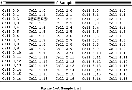 Figure 1–A Sample List
SelFlags contains selection flags for the List Manager. It’s initialized to 0; with this setting, the List Manager selects cells according to the Macintosh User Interface Guidelines. The meaning of these flags is explained below in the section “Cell Selection Algorithm”. The listFlags field contains automatic scrolling flags; the List Manager sets these flags automatically when you specify scroll bars. There are predefined constants that let you set or test the status of the corresponding bits:
CONST lDoVAutoScroll = 2; {set to allow automatic vertical scrolling}
lDoHAutoScroll = 1; {set to allow automatic horizontal scrolling}
ClikLoc is the position of the last mouse click in local coordinates; you can use it in the list definition procedure to get the position within the cell. LClikLoop is a pointer to the routine to be called during the LClick function, as described later. LastClick contains the cell coordinates of the last cell clicked in.
RefCon is the list’s reference value field, which the application may store into and access for any purpose. In addition, the application may use the field userHandle to store a handle to an additional storage area.
CellArray contains offsets to the cell data. For each list element, this includes the bit indicating whether the cell is selected or not.
»The LClikLoop Field
The lClikLoop field of a list record lets you specify a routine that will be called repeatedly (by the LClick function, described below) as long as the mouse button is held down within the rView rectangle or its scroll bars.
Note: The LClick function performs automatic scrolling if the mouse is
dragged outside the visible rectangle, so there’s no need to write
a list click loop routine to do automatic scrolling.
The list click loop routine has no parameters and returns a Boolean value. You could declare a list click loop routine named MyClikLoop like this:
FUNCTION MyClikLoop : BOOLEAN;
The function should return TRUE. You must put a pointer to your list click loop routine in the lClikLoop field of the list record so that the List Manager will call your routine.
Warning: Returning FALSE from your list click loop routine tells the
LClick function that the mouse button has been released, which
aborts LClick.
Assembly-language note: Your routine should set register D0 to 1; returning
0 in register D0 aborts LClick. For your convenience,
register D5 contains the current mouse location.
_______________________________________________________________________________
»CELL SELECTION ALGORITHM
_______________________________________________________________________________
The default algorithm used by the List Manager for user selection of cells follows the techniques described in the Macintosh User Interface Guidelines, as summarized below.
1. If neither the Shift nor the Command key is held down, a click causes
all current selections to be deselected, and the cell receiving the
click to be selected. While the mouse button is held down and the
mouse moved around, only the cell under the cursor is selected.
2. If the Shift key is held down, then as long as the mouse button is
down, the List Manager expands and shrinks a selected rectangle that’s
defined by the mouse location and the “anchor”. When the mouse is first
pressed, the List Manager calculates the smallest rectangle that encloses
all selected cells. If the click is above or to the left of this
rectangle (or on the top left corner), the bottom right corner of the
rectangle becomes the anchor; otherwise the top left corner becomes the
anchor. (If no cells are selected, the clicked cell is used as the
anchor.)
3. If the Command key is held down, then while the mouse button is down,
all cells that the mouse passes over are either selected or deselected.
Like the inversion of a bit in a bitmap, if the initial cell was off,
cells are turned on; otherwise they’re turned off.
The selFlags byte, initialized to 0 by the List Manager, contains flags that let you change the way selections work. Each flag is specified by a bit, as illustrated in Figure 2.
Figure 1–A Sample List
SelFlags contains selection flags for the List Manager. It’s initialized to 0; with this setting, the List Manager selects cells according to the Macintosh User Interface Guidelines. The meaning of these flags is explained below in the section “Cell Selection Algorithm”. The listFlags field contains automatic scrolling flags; the List Manager sets these flags automatically when you specify scroll bars. There are predefined constants that let you set or test the status of the corresponding bits:
CONST lDoVAutoScroll = 2; {set to allow automatic vertical scrolling}
lDoHAutoScroll = 1; {set to allow automatic horizontal scrolling}
ClikLoc is the position of the last mouse click in local coordinates; you can use it in the list definition procedure to get the position within the cell. LClikLoop is a pointer to the routine to be called during the LClick function, as described later. LastClick contains the cell coordinates of the last cell clicked in.
RefCon is the list’s reference value field, which the application may store into and access for any purpose. In addition, the application may use the field userHandle to store a handle to an additional storage area.
CellArray contains offsets to the cell data. For each list element, this includes the bit indicating whether the cell is selected or not.
»The LClikLoop Field
The lClikLoop field of a list record lets you specify a routine that will be called repeatedly (by the LClick function, described below) as long as the mouse button is held down within the rView rectangle or its scroll bars.
Note: The LClick function performs automatic scrolling if the mouse is
dragged outside the visible rectangle, so there’s no need to write
a list click loop routine to do automatic scrolling.
The list click loop routine has no parameters and returns a Boolean value. You could declare a list click loop routine named MyClikLoop like this:
FUNCTION MyClikLoop : BOOLEAN;
The function should return TRUE. You must put a pointer to your list click loop routine in the lClikLoop field of the list record so that the List Manager will call your routine.
Warning: Returning FALSE from your list click loop routine tells the
LClick function that the mouse button has been released, which
aborts LClick.
Assembly-language note: Your routine should set register D0 to 1; returning
0 in register D0 aborts LClick. For your convenience,
register D5 contains the current mouse location.
_______________________________________________________________________________
»CELL SELECTION ALGORITHM
_______________________________________________________________________________
The default algorithm used by the List Manager for user selection of cells follows the techniques described in the Macintosh User Interface Guidelines, as summarized below.
1. If neither the Shift nor the Command key is held down, a click causes
all current selections to be deselected, and the cell receiving the
click to be selected. While the mouse button is held down and the
mouse moved around, only the cell under the cursor is selected.
2. If the Shift key is held down, then as long as the mouse button is
down, the List Manager expands and shrinks a selected rectangle that’s
defined by the mouse location and the “anchor”. When the mouse is first
pressed, the List Manager calculates the smallest rectangle that encloses
all selected cells. If the click is above or to the left of this
rectangle (or on the top left corner), the bottom right corner of the
rectangle becomes the anchor; otherwise the top left corner becomes the
anchor. (If no cells are selected, the clicked cell is used as the
anchor.)
3. If the Command key is held down, then while the mouse button is down,
all cells that the mouse passes over are either selected or deselected.
Like the inversion of a bit in a bitmap, if the initial cell was off,
cells are turned on; otherwise they’re turned off.
The selFlags byte, initialized to 0 by the List Manager, contains flags that let you change the way selections work. Each flag is specified by a bit, as illustrated in Figure 2.
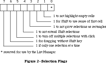 Figure 2–Selection Flags
The List Manager provides a predefined constant for each flag, in which the bit corresponding to that flag is set.
CONST lOnlyOne = –128; {set if only one selection at a time}
lExtendDrag = 64; {set for dragging without Shift key}
lNoDisjoint = 32; {set to turn off multiple selections with click}
lNoExtend = 16; {set to not extend Shift selections}
lNoRect = 8; {set to not expand selections as rectangles}
lUseSense = 4; {set for Shift to use sense of first cell}
lNoNilHilite = 2; {set to not highlight empty cells}
Setting one or more of bits 5–7 modifies the selection algorithm in the following ways:
• If you set the lOnlyOne bit, only one cell can be selected at a time.
• If you set the lNoDisjoint bit, multiple cells can be selected, but
everything is deselected when the mouse button is pressed (even if
the Shift or Command keys are held down).
• If you set the lExtendDrag bit, clicking and dragging selects all
cells in its path. (It works best if you also set lNoDisjoint, lNoRect,
lUseSense, and lNoExtend.)
Bits 2–4 affect Shift selection. If all three are set, Shift selection works exactly like Command selection.
• If you set the lNoRect bit, Shift selections are not dragged out as
rectangles, but instead select everything they pass over. They use the
anchor point, but do not shrink selections when you back over them.
• If you set the lNoExtend bit, the click is used as the anchor point for
Shift selections, and current selections are ignored.
• If you set the lUseSense bit, the cell that’s clicked determines
whether cells are turned off or on.
Bit 1, the lNoNilHilite bit, determines whether or not empty cells can be selected. If you set this bit, cells not containing data cannot be selected
(that is, the list definition procedure isn’t called to highlight empty cells).
Note: For the convenience of your application’s user, remember to conform
to the Macintosh User Interface Guidelines for selection.
_______________________________________________________________________________
»USING THE LIST MANAGER PACKAGE
_______________________________________________________________________________
The List Manager Package is automatically read into memory from the system resource file when one of its routines is called; it occupies a total of about 5K bytes.
Before using the List Manager, you must initialize QuickDraw, the Font Manager, the Window Manager, the Menu Manager, and TextEdit, in that order.
Before creating a list, you must create a window in which the drawing will take place. To create a new list, call the LNew function. When you’re done using a list, you should dispose of its data with LDispose. Before you dispose of the list, make sure you dispose of any data that you may have stored in the userHandle or refCon fields of the list record.
To change the size of a list’s cells, call LCellSize.
The procedure LDoDraw controls whether operations performed on cells by List Manager routines cause drawing on the screen.
To add rows or columns to the list, call LAddRow and LAddColumn. To delete rows or columns, call LDelRow and LDelColumn. These routines do all necessary updating of the screen if you’ve set drawing on with LDoDraw.
To assign a value to a cell, call the procedure LSetCell. To append data to a cell, you can call LAddToCell; to clear the contents of a cell, call LClrCell. To get a cell’s data, call LGetCell. The new value of a cell is displayed if you’ve set drawing on.
Warning: If you add or delete rows or columns, change the data in a cell,
or call a routine that may move or purge memory, pointers (to a
cell’s data) obtained by earlier calls to the List Manager may
no longer be valid.
To select or deselect a cell, call LSetSelect. To determine whether or not a cell is selected, call LGetSelect. LGetSelect can also be used to find the next selected cell in the list.
The Window Manager NewWindow or GetNewWindow call generates an update event for the entire window. Call LUpdate in response to the update event, and all visible cells in the update region will be drawn (or redrawn). When you change the value or selection of a cell from your program, it’s redisplayed only if drawing is on. If drawing is off, you can call the procedure LDraw to display the contents of the cell.
If a mouse-down event occurs within the list’s window, call LClick. This routine tracks the mouse, selecting cells and scrolling the display as necessary. The result of LClick is a Boolean value that is TRUE if a double-click occurred. You can discover which cell received the double-click by calling LLastClick.
If an activate or deactivate event occurs for the window containing the list, you should call the procedure LActivate. This routine highlights the selected cells and scroll bars as necessary.
If the window containing the list has a size box (and you want the list to grow along with the window), call the Window Manager routines GrowWindow and SizeWindow as usual, then call LSize with the new size of the list. The list is automatically expanded to fill the new area and the scroll bars are updated accordingly. The drawing mode does not affect the updating of scroll bars in LSize.
You can find a cell with specified contents by calling LSearch. The default search routine is the International Utilities Package function IUMagIDString, but you can pass LSearch another search routine if you wish. Given a cell, you can call LNextCell to find the next cell in the list.
You can find the local coordinates of a given cell by calling LRect. To scroll the list, call LScroll. You can call LAutoScroll to make sure that the first selected cell is visible. It automatically places the first selected cell in the top left corner of the visible rectangle.
All the data in a list is stored as a single block. You can find the offset of a particular cell’s data using LFind.
_______________________________________________________________________________
»LIST MANAGER PACKAGE ROUTINES
_______________________________________________________________________________
Assembly-language note: You can invoke each of the List Manager routines
with a macro that has the same name as the routine
preceded by an underscore. These macros expand to
invoke to trap macro _Pack 0. The package determines
which routine to execute from a routine selector, an
integer that’s passed to it in a word on the stack.
The routine selectors are as follows:
lActivate .EQU 0 lAutoScroll .EQU 16
lAddColumn .EQU 4 lCellSize .EQU 20
lAddRow .EQU 8 lClick .EQU 24
lAddToCell .EQU 12 lClrCell .EQU 28
lDelColumn .EQU 32 lNew .EQU 68
lDelRow .EQU 36 lNextCell .EQU 72
lDispose .EQU 40 lRect .EQU 76
lDoDraw .EQU 44 lScroll .EQU 80
lDraw .EQU 48 lSearch .EQU 84
lFind .EQU 52 lSetCell .EQU 88
lGetCell .EQU 56 lSetSelect .EQU 92
lGetSelect .EQU 60 lSize .EQU 96
lLastClick .EQU 64 lUpdate .EQU 100
_______________________________________________________________________________
»Creating and Disposing of Lists
FUNCTION LNew (rView,dataBounds: Rect; cSize: Point;
theProc: INTEGER; theWindow: WindowPtr;
drawIt,hasGrow, scrollHoriz,scrollVert: BOOLEAN) : ListHandle;
Call LNew to create a new list. It returns a handle to the new list. The list’s grafPort is set to theWindow’s port. If drawIt is FALSE, the list is not displayed.
RView specifies, in the local coordinates of theWindow, the rectangle in which the list will be displayed. (Remember that this doesn’t include space for scroll bars. If the list, including scroll bars, is to fill the entire window, rView should be 15 points smaller in each dimension than theWindow’s portRect.)
DataBounds is the rectangle for specifying the initial array dimensions of the list. For example to preallocate space for a list that’s 5 cells across by 10 cells down, you should set dataBounds to (0,0)(5,10). If you want to allocate the space for a one-column list, set dataBounds to (0,0)(1,0) and use LAddRow.
CSize.h and cSize.v are the desired height and width of each cell in pixels; if they’re not specified, a default cell size is calculated (as described above).
TheProc is the resource ID of your list definition procedure; for a text-only list, pass 0 and the default list definition procedure (about 150 bytes in size) will be used. The list definition procedure is called to initialize itself after all other list record fields have been initialized; thus, it can use any of the values in the list record (or set particular fields, such as the indent distance).
If hasGrow is TRUE, the scroll bars are sized so that there’s room for a size box in the standard position. It’s up to the program to display the size box
(using the Window Manager procedure DrawGrowIcon). If scrollHoriz is TRUE, a horizontal scroll bar is placed immediately below rView and all horizontal scrolling functions are implemented. If scrollVert is TRUE, a vertical scroll bar is placed immediately to the right of rView and all vertical scrolling functions are implemented.
The visible rectangle is set to contain as many cells of cSize (or the default) as will fit into rView. If the cells do not fit exactly into rView, the visible rectangle is rounded up to the nearest cell. Scrolling will always allow all cells to be fully displayed. The selection flags are set to 0, and the active flag is set to TRUE.
Note: Scrolling looks best if rView is a multiple of cSize.v in height.
PROCEDURE LDispose (lHandle: ListHandle);
Call LDispose when you are through using a list. It issues a close call to the list definition procedure, and calls the Memory Manager procedure DisposHandle for the data handle, the Control Manager procedure DisposeControl for both scroll bars (if they’re there), and DisposHandle for the list record.
Note: Calling LDispose is much faster than deleting one row at a time.
_______________________________________________________________________________
»Adding and Deleting Rows and Columns
FUNCTION LAddColumn (count,colNum: INTEGER; lHandle: ListHandle) : INTEGER;
LAddColumn inserts into the given list the number of columns specified by the count parameter, starting at the column specified by colNum. Column numbers that are greater than or equal to colNum are increased by count. If colNum is not within dataBounds, new last columns are added. The number of the first added column is returned and dataBounds.right is increased by count. All cells added are empty. If there are no cells (because dataBounds.top = dataBounds.bottom), no cells are added, but dataBounds is still extended. If drawing is on and the added columns (which are empty) are visible, the list and its scroll bars are updated.
FUNCTION LAddRow (count,rowNum: INTEGER; lHandle: ListHandle) : INTEGER;
LAddRow inserts the number of rows specified by the count parameter, starting at the row specified by rowNum. Row numbers that are greater than or equal to rowNum are increased by count. If rowNum is not within dataBounds, new last rows are added. The number of the first added row is returned, and dataBounds.bottom is increased by count. All cells added are empty. If there are no cells
(because dataBounds.left = dataBounds.right), no cells are added, but dataBounds is still extended. If drawing is on and the added rows (which are empty) are visible, the list and its scroll bars are updated.
PROCEDURE LDelColumn (count,colNum: INTEGER; lHandle: ListHandle);
LDelColumn deletes the number of columns specified by the count parameter, starting with the column specified by colNum. Column numbers that are greater than colNum are decreased by count. If colNum is not within dataBounds, nothing is done. DataBounds.right is decreased by count. If drawing is on and the deleted columns were visible, the list and its scroll bars are updated.
If count is 0, or
colNum = dataBounds.left AND count > = dataBounds.right – dataBounds.left
all the data in the list is quickly deleted, dataBounds.right is set to dataBounds.left, and the number of rows is left unchanged.
PROCEDURE LDelRow (count,rowNum: INTEGER; lHandle: ListHandle);
LDelRow deletes the number of rows specified by the count parameter, starting with the row specified by rowNum. Row numbers that are greater than rowNum are decreased by count. If rowNum is not within dataBounds, nothing is done. DataBounds.bottom is decreased by count. If drawing is on and the deleted rows were visible, the list and its scroll bars are updated.
If count is 0, or
rowNum = dataBounds.top AND count > = dataBounds.bottom – dataBounds.top
all the data in the list is quickly deleted, dataBounds.bottom is set to dataBounds.top, and the number of columns is left unchanged.
_______________________________________________________________________________
»Operations on Cells
PROCEDURE LAddToCell (dataPtr: Ptr; dataLen: INTEGER; theCell: Cell;
lHandle: ListHandle);
LAddToCell appends the data pointed to by dataPtr and of length dataLen to the cell specified by theCell in lHandle. If drawing is off, you must turn drawing on and call LDraw (or LUpdate) to display the cell’s new value.
PROCEDURE LClrCell (theCell: Cell; lHandle: ListHandle);
LClrCell clears the contents of the specified cell (by setting the length to 0). If theCell is not a valid cell, nothing is done. If drawing is off, you must turn drawing on and call LDraw to display the cell’s new value (or simply call the Window Manager procedure InvalRect).
PROCEDURE LGetCell (dataPtr: Ptr; VAR dataLen: INTEGER; theCell: Cell;
lHandle: ListHandle);
Given a cell in theCell, LGetCell copies the cell’s data to the location specified by dataPtr; dataLen is the maximum number of bytes allowed. If the data is longer than dataLen, only dataLen bytes are copied into the location specified by dataPtr. If the data is shorter than dataLen, dataLen is set to the true length of the cell’s data.
PROCEDURE LSetCell (dataPtr: Ptr; dataLen: INTEGER; theCell: Cell;
lHandle: ListHandle);
LSetCell places the data pointed to by dataPtr and of length dataLen into the specified cell. It replaces any data that was already in the cell. If dataLen is 0, this is equivalent to LClrCell. If theCell is not a valid cell, nothing is done. If drawing is off, you must turn drawing on and call LDraw (or LUpdate) to display the cell’s new value.
PROCEDURE LCellSize (cSize: Point; lHandle: ListHandle);
LCellSize sets the cellSize field in the list record to cSize and updates the visible rectangle to contain cells of this size. This command should be used only before any cells have been drawn.
FUNCTION LGetSelect (next: BOOLEAN; VAR theCell: Cell;
lHandle: ListHandle) : BOOLEAN;
If next is FALSE, LGetSelect returns TRUE if the specified cell is selected, or FALSE if not. If next is TRUE, LGetSelect returns in c the cell coordinates of the next selected cell in the row that is greater than or equal to theCell. If there are no more cells in the row, it returns in theCell the cell coordinates of the next selected cell in the next row. If there are no more rows, FALSE is returned.
PROCEDURE LSetSelect (setIt: BOOLEAN; theCell: Cell; lHandle: ListHandle);
If setIt is TRUE, LSetSelect selects the cell and redraws if it is visible and was previously unselected. If setIt is FALSE, it deselects the cell and redraws if necessary.
_______________________________________________________________________________
»Mouse Location
FUNCTION LClick (pt: Point; modifiers: INTEGER;
lHandle: ListHandle) : BOOLEAN;
Call LClick when there is a mouse-down event in the destination rectangle or its scroll bars. Pt is the mouse location in local coordinates. Modifiers is the modifiers word from the event record. LHandle is the list to be tracked. The result is TRUE if a double-click occurred (and the two clicks took place within the same cell).
LClick keeps control until the mouse is released; each time through its inner loop, it calls the routine whose pointer is in the lClikLoop field of the list record.
If the mouse is in the visible rectangle, cells are selected according to the state of the modifiers and the selection flags. If the mouse was in the cells but is dragged outside the list’s rectangle, the list is auto-scrolled. If the mouse was in a control, the control’s definition procedure is called to track the mouse. To discover which cell was clicked in, use the LLastClick function.
FUNCTION LLastClick (lHandle: ListHandle) : Cell;
LLastClick returns the cell coordinates of the last cell clicked in. If no cell has been clicked in since LNew, the value returned (for both integers) is negative.
Note: The value returned by this call is not the last cell double-clicked
in, or the last cell selected, but merely the last cell clicked in.
_______________________________________________________________________________
»Accessing Cells
PROCEDURE LFind (VAR offset,len: INTEGER; theCell: Cell;
lHandle: ListHandle);
Given a cell in theCell, LFind returns the offset and the length in bytes of the cell’s data. If an invalid cell is specified, offset and len are set to –1. A similar procedure, LGetCell, is more convenient to use from Pascal.
FUNCTION LNextCell (hNext,vNext: BOOLEAN; VAR theCell: Cell;
lHandle: ListHandle) : BOOLEAN;
Given a cell in theCell, LNextCell returns in theCell the next cell in the list. If both hNext and vNext are TRUE, theCell is first advanced to the next cell in the row. If there are no more cells in the row, theCell is set to the first cell in the next row. If there are no more rows, FALSE is returned. If only hNext is TRUE, theCell is advanced within the current row. If only vNext is TRUE, theCell is advanced within the current column. FALSE is returned if there are no remaining cells in the row or column.
PROCEDURE LRect (VAR cellRect: Rect; theCell: Cell; lHandle: ListHandle);
LRect returns in cellRect the local (QuickDraw) coordinates of the cell specified by theCell. If an invalid cell is specified, (0,0)(0,0) is returned in cellRect.
FUNCTION LSearch (dataPtr: Ptr; dataLen: INTEGER; searchProc: Ptr;
VAR theCell: Cell; lHandle: ListHandle) : BOOLEAN;
LSearch searches for the first cell greater than or equal to theCell that contains the specified data. If a cell containing matching data is found, the function result TRUE is returned, and the cell coordinates are returned in theCell. If searchProc is NIL, the International Utilities Package function IUMagIDString is called to compare the specified data with the contents of each cell. If searchProc is not NIL, the routine pointed to by searchProc is called.
Note: Your searchProc should have the same parameters as the
IUMagIDString function.
PROCEDURE LSize (listWidth,listHeight: INTEGER; lHandle: ListHandle);
You’ll usually call LSize immediately after the Window Manager procedure SizeWindow. It causes the bottom right of the list to be adjusted so that the list is the width and height indicated by listWidth and listHeight. The contents of the list and the scroll bars are adjusted and redrawn as necessary. The values of listWidth and listHeight do not include the scroll bars; for a list that entirely fills the window, listWidth and listHeight should be 15 fewer pixels than the portRect if both scroll bars are present.
_______________________________________________________________________________
»List Display
PROCEDURE LDraw (theCell: Cell; lHandle: ListHandle);
Call LDraw after updating a cell’s data or selection status. (You can achieve the same result by invalidating the cell’s rectangle and calling LUpdate in response to the update event.) The List Manager makes its grafPort the current port, sets the clipping region to the cell’s rectangle, and calls the list definition procedure to draw the cell. It restores the clipping region and port before exiting.
PROCEDURE LDoDraw (drawIt: BOOLEAN; lHandle: ListHandle);
LDoDraw sets the List Manager’s drawing mode to the state specified by drawIt. If drawIt is TRUE, changes made by most List Manager calls will cause some sort of drawing to take place. If drawIt is FALSE, all cell drawing is disabled.
(Two exceptions: The scroll bars are still updated after LSize, and the scroll arrows are still highlighted if the user clicks them.)
The recommended use of LDoDraw is to disable drawing while you’re building a list (that is, adding rows or columns, setting or changing cell values, or setting default selections). Once you’ve finished building the list, you should then re-enable drawing. In general, drawing should be on while you’re in your event loop and dispatching events to the List Manager.
PROCEDURE LScroll (dCols,dRows: INTEGER; lHandle: ListHandle);
LScroll scrolls the given list by the number of columns and rows specified in dCols and dRows, either positively (down and to the right) or negatively (up and to the left). Scrolling is pinned to the list’s dataBounds. If drawing is on, LScroll does all necessary updating of the screen.
PROCEDURE LAutoScroll (lHandle: ListHandle);
For the given list, LAutoScroll scrolls the list until the first selected cell is visible. It automatically places the first selected cell in the top left corner of the visible rectangle.
PROCEDURE LUpdate (theRgn: RgnHandle; lHandle: ListHandle);
LUpdate should be called in response to an update event. TheRgn should be set to the visRgn of the list’s port (for more details, see the BeginUpdate procedure in the Window Manager chapter). It redraws any visible cells in lHandle that intersect theRgn. It also redraws the controls, if necessary.
PROCEDURE LActivate (act: BOOLEAN; lHandle: ListHandle);
Call LActivate to activate or deactivate the list specified by lHandle (in response to an activate event in the window containing the list). The act parameter should be set to TRUE to activate the list, or FALSE to deactivate the list. LActivate highlights or unhighlights the selections, and shows or hides the scroll bars (but not the size box, if any).
_______________________________________________________________________________
»DEFINING YOUR OWN LISTS
_______________________________________________________________________________
The List Manager calls a list definition procedure to perform any additional list initialization (such as the allocation of storage space for the application), to draw a cell, to invert the highlight state of a cell, and to dispose of any data it may have allocated. The system resource file includes a default list definition procedure for a standard text-only list; you may, however, wish to define your own type of list with special features.
To define your own type of list, you write a list definition procedure and store it in a resource file as a resource of type 'LDEF'. The standard list definition procedure has a resource ID of 0; your definition procedure should have a different ID.
When you create a list, you provide the resource ID of the list definition procedure to be used. The List Manager calls the Resource Manager to access the list definition procedure with the given resource ID. The Resource Manager reads the list definition procedure into memory and returns a handle to it. The List Manager then stores this handle in the listDefProc field of the list record.
_______________________________________________________________________________
»The List Definition Procedure
The list definition procedure is usually written in assembly language, but may be written in Pascal.
Assembly-language note: The procedure’s entry point must be at the beginning.
You may choose any name you wish for your list definition procedure. Here’s how you would declare one named MyList:
PROCEDURE MyList (lMessage: INTEGER; lSelect: BOOLEAN; lRect: Rect;
lCell: Cell; lDataOffset,lDataLen: INTEGER;
lHandle: ListHandle);
The lMessage parameter identifies the operation to be performed. It has one of the following values:
CONST lInitMsg = 0; {do any additional list initialization}
lDrawMsg = 1; {draw the cell }
lHiliteMsg = 2; {invert cell's highlight state}
lCloseMsg = 3; {take any additional disposal action}
LSelect is used for both the drawing and highlighting operations; it’s TRUE if the cell should be selected.
LRect indicates the rectangle in which a cell should be drawn. LDataOffset is the offset into the cell data of the cell to be drawn or highlighted; lDataLen is the length in bytes of that cell’s data. LHandle is the handle to the list record.
The routines that perform these operations are described below.
Note: “Routine” here doesn’t necessarily mean a procedure or function.
While it’s a good idea to set these up as subfunctions within the
list definition procedure, you’re not required to do so.
_______________________________________________________________________________
»The Initialize Routine
The list definition procedure is called by the LNew function with an initMsg message after all list initialization has been completed. Since all default settings have been stored in the list record, this routine is a good place to change any of these settings. This routine can also be used to allocate any private storage needed by the list definition procedure.
_______________________________________________________________________________
»The Draw Routine
The list definition procedure receives a lDrawMsg message when a cell needs to be drawn. The lSelect parameter is TRUE if the given cell should be selected.
LRect is the rectangle in which the cell should be drawn. The draw routine sets the clipping region of the list’s window to this rectangle.
LDataOffset is the offset into the cell data of the cell to be drawn; lDataLen is the length of that cell’s data in bytes.
_______________________________________________________________________________
»The Highlight Routine
The definition procedure receives a lHiliteMsg message when a cell’s data is visible and its highlight state needs to be inverted (from selected to deselected or vice versa). This routine is provided for the extra speed usually gained by using an invert operation instead of a combination of the draw and highlight operations.
The parameters for this routine are identical to those for the lDrawMsg routine. If you want (for instance, if highlighting is more complicated than mere inversion), you can simply call your lDrawMsg routine when you get a lHiliteMsg message.
_______________________________________________________________________________
»The Close Routine
The definition procedure receives a lCloseMsg message in response to a LDispose call. If any private storage was allocated by the definition procedure, this routine should dispose of it.
_______________________________________________________________________________
»SUMMARY OF THE LIST MANAGER PACKAGE
_______________________________________________________________________________
Constants
CONST
{ Masks for automatic scrolling }
lDoVAutoscroll = 2 {set to allow automatic vertical scrolling}
lDoHAutoscroll = 1 {set to allow automatic horizontal scrolling}
{ Masks for selection flags }
lOnlyOne = –128; {set if only one selection at a time}
lExtendDrag = 64; {set for dragging without Shift key}
lNoDisjoint = 32; {set to turn off multiple selections with click}
lNoExtend = 16; {set to not extend Shift selections}
lNoRect = 8; {set to not grow selections as rectangles}
lUseSense = 4; {set for Shift to use sense of first cell}
lNoNilHilite = 2; {set to not highlight empty cells}
{ Messages to list definition procedure }
lInitMsg = 0; {initialize list, set defaults, allocate space}
lDrawMsg = 1; {draw the indicated cell data}
lHiliteMsg = 2; {invert (select/deselect) the state of a cell}
lCloseMsg = 3; {dispose of list and any associated data}
_______________________________________________________________________________
Data Types
TYPE
Cell = Point;
DataArray = PACKED ARRAY [0..32000] OF CHAR;
DataPtr = ^DataArray;
DataHandle = ^DataPtr;
ListRec = RECORD
rView: Rect; {list's display rectangle}
port: GrafPtr; {list's grafPort}
indent: Point; {indent distance}
cellSize: Point; {cell size}
visible: Rect; {boundary of visible cells}
vScroll: ControlHandle; {vertical scroll bar}
hScroll: ControlHandle; {horizontal scroll bar}
selFlags: SignedByte; {selection flags}
lActive: BOOLEAN; {TRUE if active}
lReserved: SignedByte; {reserved}
listFlags: SignedByte; {automatic scrolling flags}
clikTime: LONGINT; {time of last click}
clikLoc: Point; {position of last click}
mouseLoc: Point; {current mouse location}
lClikLoop: Ptr; {routine for LClick}
lastClick: Cell; {last cell clicked}
refCon: LONGINT; {list's reference value}
listDefProc: Handle; {list definition procedure}
userHandle: Handle; {additional storage}
dataBounds: Rect; {boundary of cells allocated}
cells: DataHandle; {cell data}
maxIndex: INTEGER; {used internally}
cellArray: ARRAY [1..1] OF INTEGER {offsets to data}
END;
ListPtr = ^ListRec;
ListHandle = ^ListPtr;
_______________________________________________________________________________
Routines
Creating and Disposing of Lists
FUNCTION LNew (rView,dataBounds: Rect; cSize: Point;
theProc: INTEGER; theWindow: WindowPtr;
drawIt, hasGrow,scrollHoriz,scrollVert: BOOLEAN) :
ListHandle;
PROCEDURE LDispose (lHandle: ListHandle);
Adding and Deleting Rows and Columns
FUNCTION LAddColumn (count,colNum: INTEGER; lHandle: ListHandle) : INTEGER;
FUNCTION LAddRow (count,rowNum: INTEGER; lHandle: ListHandle) : INTEGER;
PROCEDURE LDelColumn (count,colNum: INTEGER; lHandle: ListHandle);
PROCEDURE LDelRow (count,rowNum: INTEGER; lHandle: ListHandle);
Operations on Cells
PROCEDURE LAddToCell (dataPtr: Ptr; dataLen: INTEGER; theCell: Cell;
lHandle: ListHandle);
PROCEDURE LClrCell (theCell: Cell; lHandle: ListHandle);
PROCEDURE LGetCell (dataPtr: Ptr; VAR dataLen: INTEGER; theCell: Cell;
lHandle: ListHandle);
PROCEDURE LSetCell (dataPtr: Ptr; dataLen: INTEGER; theCell: Cell;
lHandle: ListHandle);
PROCEDURE LCellSize (cSize: Point; lHandle: ListHandle );
FUNCTION LGetSelect (next: BOOLEAN; VAR theCell: Cell;
lHandle: ListHandle) : BOOLEAN;
PROCEDURE LSetSelect (setIt: BOOLEAN; theCell: Cell; lHandle: ListHandle);
Mouse Location
FUNCTION LClick (pt: Point; modifiers: INTEGER;
lHandle: ListHandle) : BOOLEAN;
FUNCTION LLastClick (lHandle: ListHandle) : Cell;
Accessing Cells
PROCEDURE LFind (VAR offset,len: INTEGER; theCell: Cell;
lHandle: ListHandle);
FUNCTION LNextCell (hNext,vNext: BOOLEAN; VAR theCell: Cell;
lHandle: ListHandle) : BOOLEAN
PROCEDURE LRect (VAR cellRect: Rect; theCell: Cell; lHandle: ListHandle);
FUNCTION LSearch (dataPtr: Ptr; dataLen: INTEGER; searchProc: Ptr;
VAR theCell: Cell; lHandle: ListHandle) : BOOLEAN;
PROCEDURE LSize (listWidth,listHeight: INTEGER; lHandle: ListHandle);
List Display
PROCEDURE LDraw (theCell: Cell; lHandle: ListHandle);
PROCEDURE LDoDraw (drawIt: BOOLEAN; lHandle: ListHandle);
PROCEDURE LScroll (dCols,dRows: INTEGER; lHandle: ListHandle);
PROCEDURE LAutoScroll (lHandle: ListHandle);
PROCEDURE LUpdate (theRgn: RgnHandle; lHandle: ListHandle);
PROCEDURE LActivate (act: BOOLEAN; lHandle: ListHandle);
_______________________________________________________________________________
List Definition Procedure
PROCEDURE MyListDef (lMessage: INTEGER; lSelect: BOOLEAN; lRect: Rect;
lCell: Cell; lDataOffset,lDataLen: INTEGER;
lHandle: ListHandle);
_______________________________________________________________________________
Assembly-Language Information
Constants
; Automatic scrolling flags
lDoVAutoscroll .EQU 1 ;set to allow automatic vertical scrolling
lDoHAutoscroll .EQU 0 ;set to allow automatic horizontal scrolling
; Selection flags
lOnlyOne .EQU 7 ;set if only one selection at a time
lExtendDrag .EQU 6 ;set for dragging without Shift key
lNoDisjoint .EQU 5 ;set to turn off multiple selections with click
lNoExtend .EQU 4 ;set to not extend Shift selections
lNoRect .EQU 3 ;set to not grow selections as rectangles
lUseSense .EQU 2 ;set for Shift to use sense of first cell
lNoNilHilite .EQU 1 ;set to not highlight empty cells
; Messages to list definition procedure
lInitMsg .EQU 0 ;initialize list, set defaults, allocate space
lDrawMsg .EQU 1 ;draw the indicated cell data
lHiliteMsg .EQU 2 ;invert (select/deselect) the state of a cell
lCloseMsg .EQU 3 ;dispose of list and any associated data
; Routine selectors
; (Note: You can invoke each of the List Manager routines with a macro
; that has the same name as the routine preceded by an underscore.)
lActivate .EQU 0
lAddColumn .EQU 4
lAddRow .EQU 8
lAddToCell .EQU 12
lAutoScroll .EQU 16
lCellSize .EQU 20
lClick .EQU 24
lClrCell .EQU 28
lDelColumn .EQU 32
lDelRow .EQU 36
lDispose .EQU 40
lDoDraw .EQU 44
lDraw .EQU 48
lFind .EQU 52
lGetCell .EQU 56
lGetSelect .EQU 60
lLastClick .EQU 64
lNew .EQU 68
lNextCell .EQU 72
lRect .EQU 76
lScroll .EQU 80
lSearch .EQU 84
lSetCell .EQU 88
lSetSelect .EQU 92
lSize .EQU 96
lUpdate .EQU 100
List Record Data Structure
rView List’s display rectangle (rectangle; 8 bytes)
port List’s grafPort (portRec bytes)
indent Indent distance (point; long)
cellSize Cell size (point; long)
visible Boundary of visible cells (rectangle; 8 bytes)
vScroll Handle to vertical scroll bar
hScroll Handle to horizontal scroll bar
selFlags Selection flags (byte)
lActive Nonzero if active (byte)
clikTime Time of last click (long)
clikLoc Position of last click (point; long)
mouseLoc Current mouse location (point; long)
lClikLoop Pointer to routine to be called during LClick
lastClick Last cell clicked (point; long)
refCon Reference value (long)
listDefHandle Handle to list definition procedure
userHandle Handle to user storage
dataBounds Boundary of cells allocated (rectangle; 8 bytes)
cells Handle to cell data
maxIndex Used internally (word)
cellArray Offsets to cells
Trap Macro Name
_Pack0
(Note: You can invoke each of the List Manager routines with a macro that has the same name as the routine preceded by an underscore.)
Further Reference:
_______________________________________________________________________________
Resource Manager
QuickDraw
Toolbox Event Manager
Window Manager
Package Manager
Technical Note #203, Don’t Abuse the Managers
Figure 2–Selection Flags
The List Manager provides a predefined constant for each flag, in which the bit corresponding to that flag is set.
CONST lOnlyOne = –128; {set if only one selection at a time}
lExtendDrag = 64; {set for dragging without Shift key}
lNoDisjoint = 32; {set to turn off multiple selections with click}
lNoExtend = 16; {set to not extend Shift selections}
lNoRect = 8; {set to not expand selections as rectangles}
lUseSense = 4; {set for Shift to use sense of first cell}
lNoNilHilite = 2; {set to not highlight empty cells}
Setting one or more of bits 5–7 modifies the selection algorithm in the following ways:
• If you set the lOnlyOne bit, only one cell can be selected at a time.
• If you set the lNoDisjoint bit, multiple cells can be selected, but
everything is deselected when the mouse button is pressed (even if
the Shift or Command keys are held down).
• If you set the lExtendDrag bit, clicking and dragging selects all
cells in its path. (It works best if you also set lNoDisjoint, lNoRect,
lUseSense, and lNoExtend.)
Bits 2–4 affect Shift selection. If all three are set, Shift selection works exactly like Command selection.
• If you set the lNoRect bit, Shift selections are not dragged out as
rectangles, but instead select everything they pass over. They use the
anchor point, but do not shrink selections when you back over them.
• If you set the lNoExtend bit, the click is used as the anchor point for
Shift selections, and current selections are ignored.
• If you set the lUseSense bit, the cell that’s clicked determines
whether cells are turned off or on.
Bit 1, the lNoNilHilite bit, determines whether or not empty cells can be selected. If you set this bit, cells not containing data cannot be selected
(that is, the list definition procedure isn’t called to highlight empty cells).
Note: For the convenience of your application’s user, remember to conform
to the Macintosh User Interface Guidelines for selection.
_______________________________________________________________________________
»USING THE LIST MANAGER PACKAGE
_______________________________________________________________________________
The List Manager Package is automatically read into memory from the system resource file when one of its routines is called; it occupies a total of about 5K bytes.
Before using the List Manager, you must initialize QuickDraw, the Font Manager, the Window Manager, the Menu Manager, and TextEdit, in that order.
Before creating a list, you must create a window in which the drawing will take place. To create a new list, call the LNew function. When you’re done using a list, you should dispose of its data with LDispose. Before you dispose of the list, make sure you dispose of any data that you may have stored in the userHandle or refCon fields of the list record.
To change the size of a list’s cells, call LCellSize.
The procedure LDoDraw controls whether operations performed on cells by List Manager routines cause drawing on the screen.
To add rows or columns to the list, call LAddRow and LAddColumn. To delete rows or columns, call LDelRow and LDelColumn. These routines do all necessary updating of the screen if you’ve set drawing on with LDoDraw.
To assign a value to a cell, call the procedure LSetCell. To append data to a cell, you can call LAddToCell; to clear the contents of a cell, call LClrCell. To get a cell’s data, call LGetCell. The new value of a cell is displayed if you’ve set drawing on.
Warning: If you add or delete rows or columns, change the data in a cell,
or call a routine that may move or purge memory, pointers (to a
cell’s data) obtained by earlier calls to the List Manager may
no longer be valid.
To select or deselect a cell, call LSetSelect. To determine whether or not a cell is selected, call LGetSelect. LGetSelect can also be used to find the next selected cell in the list.
The Window Manager NewWindow or GetNewWindow call generates an update event for the entire window. Call LUpdate in response to the update event, and all visible cells in the update region will be drawn (or redrawn). When you change the value or selection of a cell from your program, it’s redisplayed only if drawing is on. If drawing is off, you can call the procedure LDraw to display the contents of the cell.
If a mouse-down event occurs within the list’s window, call LClick. This routine tracks the mouse, selecting cells and scrolling the display as necessary. The result of LClick is a Boolean value that is TRUE if a double-click occurred. You can discover which cell received the double-click by calling LLastClick.
If an activate or deactivate event occurs for the window containing the list, you should call the procedure LActivate. This routine highlights the selected cells and scroll bars as necessary.
If the window containing the list has a size box (and you want the list to grow along with the window), call the Window Manager routines GrowWindow and SizeWindow as usual, then call LSize with the new size of the list. The list is automatically expanded to fill the new area and the scroll bars are updated accordingly. The drawing mode does not affect the updating of scroll bars in LSize.
You can find a cell with specified contents by calling LSearch. The default search routine is the International Utilities Package function IUMagIDString, but you can pass LSearch another search routine if you wish. Given a cell, you can call LNextCell to find the next cell in the list.
You can find the local coordinates of a given cell by calling LRect. To scroll the list, call LScroll. You can call LAutoScroll to make sure that the first selected cell is visible. It automatically places the first selected cell in the top left corner of the visible rectangle.
All the data in a list is stored as a single block. You can find the offset of a particular cell’s data using LFind.
_______________________________________________________________________________
»LIST MANAGER PACKAGE ROUTINES
_______________________________________________________________________________
Assembly-language note: You can invoke each of the List Manager routines
with a macro that has the same name as the routine
preceded by an underscore. These macros expand to
invoke to trap macro _Pack 0. The package determines
which routine to execute from a routine selector, an
integer that’s passed to it in a word on the stack.
The routine selectors are as follows:
lActivate .EQU 0 lAutoScroll .EQU 16
lAddColumn .EQU 4 lCellSize .EQU 20
lAddRow .EQU 8 lClick .EQU 24
lAddToCell .EQU 12 lClrCell .EQU 28
lDelColumn .EQU 32 lNew .EQU 68
lDelRow .EQU 36 lNextCell .EQU 72
lDispose .EQU 40 lRect .EQU 76
lDoDraw .EQU 44 lScroll .EQU 80
lDraw .EQU 48 lSearch .EQU 84
lFind .EQU 52 lSetCell .EQU 88
lGetCell .EQU 56 lSetSelect .EQU 92
lGetSelect .EQU 60 lSize .EQU 96
lLastClick .EQU 64 lUpdate .EQU 100
_______________________________________________________________________________
»Creating and Disposing of Lists
FUNCTION LNew (rView,dataBounds: Rect; cSize: Point;
theProc: INTEGER; theWindow: WindowPtr;
drawIt,hasGrow, scrollHoriz,scrollVert: BOOLEAN) : ListHandle;
Call LNew to create a new list. It returns a handle to the new list. The list’s grafPort is set to theWindow’s port. If drawIt is FALSE, the list is not displayed.
RView specifies, in the local coordinates of theWindow, the rectangle in which the list will be displayed. (Remember that this doesn’t include space for scroll bars. If the list, including scroll bars, is to fill the entire window, rView should be 15 points smaller in each dimension than theWindow’s portRect.)
DataBounds is the rectangle for specifying the initial array dimensions of the list. For example to preallocate space for a list that’s 5 cells across by 10 cells down, you should set dataBounds to (0,0)(5,10). If you want to allocate the space for a one-column list, set dataBounds to (0,0)(1,0) and use LAddRow.
CSize.h and cSize.v are the desired height and width of each cell in pixels; if they’re not specified, a default cell size is calculated (as described above).
TheProc is the resource ID of your list definition procedure; for a text-only list, pass 0 and the default list definition procedure (about 150 bytes in size) will be used. The list definition procedure is called to initialize itself after all other list record fields have been initialized; thus, it can use any of the values in the list record (or set particular fields, such as the indent distance).
If hasGrow is TRUE, the scroll bars are sized so that there’s room for a size box in the standard position. It’s up to the program to display the size box
(using the Window Manager procedure DrawGrowIcon). If scrollHoriz is TRUE, a horizontal scroll bar is placed immediately below rView and all horizontal scrolling functions are implemented. If scrollVert is TRUE, a vertical scroll bar is placed immediately to the right of rView and all vertical scrolling functions are implemented.
The visible rectangle is set to contain as many cells of cSize (or the default) as will fit into rView. If the cells do not fit exactly into rView, the visible rectangle is rounded up to the nearest cell. Scrolling will always allow all cells to be fully displayed. The selection flags are set to 0, and the active flag is set to TRUE.
Note: Scrolling looks best if rView is a multiple of cSize.v in height.
PROCEDURE LDispose (lHandle: ListHandle);
Call LDispose when you are through using a list. It issues a close call to the list definition procedure, and calls the Memory Manager procedure DisposHandle for the data handle, the Control Manager procedure DisposeControl for both scroll bars (if they’re there), and DisposHandle for the list record.
Note: Calling LDispose is much faster than deleting one row at a time.
_______________________________________________________________________________
»Adding and Deleting Rows and Columns
FUNCTION LAddColumn (count,colNum: INTEGER; lHandle: ListHandle) : INTEGER;
LAddColumn inserts into the given list the number of columns specified by the count parameter, starting at the column specified by colNum. Column numbers that are greater than or equal to colNum are increased by count. If colNum is not within dataBounds, new last columns are added. The number of the first added column is returned and dataBounds.right is increased by count. All cells added are empty. If there are no cells (because dataBounds.top = dataBounds.bottom), no cells are added, but dataBounds is still extended. If drawing is on and the added columns (which are empty) are visible, the list and its scroll bars are updated.
FUNCTION LAddRow (count,rowNum: INTEGER; lHandle: ListHandle) : INTEGER;
LAddRow inserts the number of rows specified by the count parameter, starting at the row specified by rowNum. Row numbers that are greater than or equal to rowNum are increased by count. If rowNum is not within dataBounds, new last rows are added. The number of the first added row is returned, and dataBounds.bottom is increased by count. All cells added are empty. If there are no cells
(because dataBounds.left = dataBounds.right), no cells are added, but dataBounds is still extended. If drawing is on and the added rows (which are empty) are visible, the list and its scroll bars are updated.
PROCEDURE LDelColumn (count,colNum: INTEGER; lHandle: ListHandle);
LDelColumn deletes the number of columns specified by the count parameter, starting with the column specified by colNum. Column numbers that are greater than colNum are decreased by count. If colNum is not within dataBounds, nothing is done. DataBounds.right is decreased by count. If drawing is on and the deleted columns were visible, the list and its scroll bars are updated.
If count is 0, or
colNum = dataBounds.left AND count > = dataBounds.right – dataBounds.left
all the data in the list is quickly deleted, dataBounds.right is set to dataBounds.left, and the number of rows is left unchanged.
PROCEDURE LDelRow (count,rowNum: INTEGER; lHandle: ListHandle);
LDelRow deletes the number of rows specified by the count parameter, starting with the row specified by rowNum. Row numbers that are greater than rowNum are decreased by count. If rowNum is not within dataBounds, nothing is done. DataBounds.bottom is decreased by count. If drawing is on and the deleted rows were visible, the list and its scroll bars are updated.
If count is 0, or
rowNum = dataBounds.top AND count > = dataBounds.bottom – dataBounds.top
all the data in the list is quickly deleted, dataBounds.bottom is set to dataBounds.top, and the number of columns is left unchanged.
_______________________________________________________________________________
»Operations on Cells
PROCEDURE LAddToCell (dataPtr: Ptr; dataLen: INTEGER; theCell: Cell;
lHandle: ListHandle);
LAddToCell appends the data pointed to by dataPtr and of length dataLen to the cell specified by theCell in lHandle. If drawing is off, you must turn drawing on and call LDraw (or LUpdate) to display the cell’s new value.
PROCEDURE LClrCell (theCell: Cell; lHandle: ListHandle);
LClrCell clears the contents of the specified cell (by setting the length to 0). If theCell is not a valid cell, nothing is done. If drawing is off, you must turn drawing on and call LDraw to display the cell’s new value (or simply call the Window Manager procedure InvalRect).
PROCEDURE LGetCell (dataPtr: Ptr; VAR dataLen: INTEGER; theCell: Cell;
lHandle: ListHandle);
Given a cell in theCell, LGetCell copies the cell’s data to the location specified by dataPtr; dataLen is the maximum number of bytes allowed. If the data is longer than dataLen, only dataLen bytes are copied into the location specified by dataPtr. If the data is shorter than dataLen, dataLen is set to the true length of the cell’s data.
PROCEDURE LSetCell (dataPtr: Ptr; dataLen: INTEGER; theCell: Cell;
lHandle: ListHandle);
LSetCell places the data pointed to by dataPtr and of length dataLen into the specified cell. It replaces any data that was already in the cell. If dataLen is 0, this is equivalent to LClrCell. If theCell is not a valid cell, nothing is done. If drawing is off, you must turn drawing on and call LDraw (or LUpdate) to display the cell’s new value.
PROCEDURE LCellSize (cSize: Point; lHandle: ListHandle);
LCellSize sets the cellSize field in the list record to cSize and updates the visible rectangle to contain cells of this size. This command should be used only before any cells have been drawn.
FUNCTION LGetSelect (next: BOOLEAN; VAR theCell: Cell;
lHandle: ListHandle) : BOOLEAN;
If next is FALSE, LGetSelect returns TRUE if the specified cell is selected, or FALSE if not. If next is TRUE, LGetSelect returns in c the cell coordinates of the next selected cell in the row that is greater than or equal to theCell. If there are no more cells in the row, it returns in theCell the cell coordinates of the next selected cell in the next row. If there are no more rows, FALSE is returned.
PROCEDURE LSetSelect (setIt: BOOLEAN; theCell: Cell; lHandle: ListHandle);
If setIt is TRUE, LSetSelect selects the cell and redraws if it is visible and was previously unselected. If setIt is FALSE, it deselects the cell and redraws if necessary.
_______________________________________________________________________________
»Mouse Location
FUNCTION LClick (pt: Point; modifiers: INTEGER;
lHandle: ListHandle) : BOOLEAN;
Call LClick when there is a mouse-down event in the destination rectangle or its scroll bars. Pt is the mouse location in local coordinates. Modifiers is the modifiers word from the event record. LHandle is the list to be tracked. The result is TRUE if a double-click occurred (and the two clicks took place within the same cell).
LClick keeps control until the mouse is released; each time through its inner loop, it calls the routine whose pointer is in the lClikLoop field of the list record.
If the mouse is in the visible rectangle, cells are selected according to the state of the modifiers and the selection flags. If the mouse was in the cells but is dragged outside the list’s rectangle, the list is auto-scrolled. If the mouse was in a control, the control’s definition procedure is called to track the mouse. To discover which cell was clicked in, use the LLastClick function.
FUNCTION LLastClick (lHandle: ListHandle) : Cell;
LLastClick returns the cell coordinates of the last cell clicked in. If no cell has been clicked in since LNew, the value returned (for both integers) is negative.
Note: The value returned by this call is not the last cell double-clicked
in, or the last cell selected, but merely the last cell clicked in.
_______________________________________________________________________________
»Accessing Cells
PROCEDURE LFind (VAR offset,len: INTEGER; theCell: Cell;
lHandle: ListHandle);
Given a cell in theCell, LFind returns the offset and the length in bytes of the cell’s data. If an invalid cell is specified, offset and len are set to –1. A similar procedure, LGetCell, is more convenient to use from Pascal.
FUNCTION LNextCell (hNext,vNext: BOOLEAN; VAR theCell: Cell;
lHandle: ListHandle) : BOOLEAN;
Given a cell in theCell, LNextCell returns in theCell the next cell in the list. If both hNext and vNext are TRUE, theCell is first advanced to the next cell in the row. If there are no more cells in the row, theCell is set to the first cell in the next row. If there are no more rows, FALSE is returned. If only hNext is TRUE, theCell is advanced within the current row. If only vNext is TRUE, theCell is advanced within the current column. FALSE is returned if there are no remaining cells in the row or column.
PROCEDURE LRect (VAR cellRect: Rect; theCell: Cell; lHandle: ListHandle);
LRect returns in cellRect the local (QuickDraw) coordinates of the cell specified by theCell. If an invalid cell is specified, (0,0)(0,0) is returned in cellRect.
FUNCTION LSearch (dataPtr: Ptr; dataLen: INTEGER; searchProc: Ptr;
VAR theCell: Cell; lHandle: ListHandle) : BOOLEAN;
LSearch searches for the first cell greater than or equal to theCell that contains the specified data. If a cell containing matching data is found, the function result TRUE is returned, and the cell coordinates are returned in theCell. If searchProc is NIL, the International Utilities Package function IUMagIDString is called to compare the specified data with the contents of each cell. If searchProc is not NIL, the routine pointed to by searchProc is called.
Note: Your searchProc should have the same parameters as the
IUMagIDString function.
PROCEDURE LSize (listWidth,listHeight: INTEGER; lHandle: ListHandle);
You’ll usually call LSize immediately after the Window Manager procedure SizeWindow. It causes the bottom right of the list to be adjusted so that the list is the width and height indicated by listWidth and listHeight. The contents of the list and the scroll bars are adjusted and redrawn as necessary. The values of listWidth and listHeight do not include the scroll bars; for a list that entirely fills the window, listWidth and listHeight should be 15 fewer pixels than the portRect if both scroll bars are present.
_______________________________________________________________________________
»List Display
PROCEDURE LDraw (theCell: Cell; lHandle: ListHandle);
Call LDraw after updating a cell’s data or selection status. (You can achieve the same result by invalidating the cell’s rectangle and calling LUpdate in response to the update event.) The List Manager makes its grafPort the current port, sets the clipping region to the cell’s rectangle, and calls the list definition procedure to draw the cell. It restores the clipping region and port before exiting.
PROCEDURE LDoDraw (drawIt: BOOLEAN; lHandle: ListHandle);
LDoDraw sets the List Manager’s drawing mode to the state specified by drawIt. If drawIt is TRUE, changes made by most List Manager calls will cause some sort of drawing to take place. If drawIt is FALSE, all cell drawing is disabled.
(Two exceptions: The scroll bars are still updated after LSize, and the scroll arrows are still highlighted if the user clicks them.)
The recommended use of LDoDraw is to disable drawing while you’re building a list (that is, adding rows or columns, setting or changing cell values, or setting default selections). Once you’ve finished building the list, you should then re-enable drawing. In general, drawing should be on while you’re in your event loop and dispatching events to the List Manager.
PROCEDURE LScroll (dCols,dRows: INTEGER; lHandle: ListHandle);
LScroll scrolls the given list by the number of columns and rows specified in dCols and dRows, either positively (down and to the right) or negatively (up and to the left). Scrolling is pinned to the list’s dataBounds. If drawing is on, LScroll does all necessary updating of the screen.
PROCEDURE LAutoScroll (lHandle: ListHandle);
For the given list, LAutoScroll scrolls the list until the first selected cell is visible. It automatically places the first selected cell in the top left corner of the visible rectangle.
PROCEDURE LUpdate (theRgn: RgnHandle; lHandle: ListHandle);
LUpdate should be called in response to an update event. TheRgn should be set to the visRgn of the list’s port (for more details, see the BeginUpdate procedure in the Window Manager chapter). It redraws any visible cells in lHandle that intersect theRgn. It also redraws the controls, if necessary.
PROCEDURE LActivate (act: BOOLEAN; lHandle: ListHandle);
Call LActivate to activate or deactivate the list specified by lHandle (in response to an activate event in the window containing the list). The act parameter should be set to TRUE to activate the list, or FALSE to deactivate the list. LActivate highlights or unhighlights the selections, and shows or hides the scroll bars (but not the size box, if any).
_______________________________________________________________________________
»DEFINING YOUR OWN LISTS
_______________________________________________________________________________
The List Manager calls a list definition procedure to perform any additional list initialization (such as the allocation of storage space for the application), to draw a cell, to invert the highlight state of a cell, and to dispose of any data it may have allocated. The system resource file includes a default list definition procedure for a standard text-only list; you may, however, wish to define your own type of list with special features.
To define your own type of list, you write a list definition procedure and store it in a resource file as a resource of type 'LDEF'. The standard list definition procedure has a resource ID of 0; your definition procedure should have a different ID.
When you create a list, you provide the resource ID of the list definition procedure to be used. The List Manager calls the Resource Manager to access the list definition procedure with the given resource ID. The Resource Manager reads the list definition procedure into memory and returns a handle to it. The List Manager then stores this handle in the listDefProc field of the list record.
_______________________________________________________________________________
»The List Definition Procedure
The list definition procedure is usually written in assembly language, but may be written in Pascal.
Assembly-language note: The procedure’s entry point must be at the beginning.
You may choose any name you wish for your list definition procedure. Here’s how you would declare one named MyList:
PROCEDURE MyList (lMessage: INTEGER; lSelect: BOOLEAN; lRect: Rect;
lCell: Cell; lDataOffset,lDataLen: INTEGER;
lHandle: ListHandle);
The lMessage parameter identifies the operation to be performed. It has one of the following values:
CONST lInitMsg = 0; {do any additional list initialization}
lDrawMsg = 1; {draw the cell }
lHiliteMsg = 2; {invert cell's highlight state}
lCloseMsg = 3; {take any additional disposal action}
LSelect is used for both the drawing and highlighting operations; it’s TRUE if the cell should be selected.
LRect indicates the rectangle in which a cell should be drawn. LDataOffset is the offset into the cell data of the cell to be drawn or highlighted; lDataLen is the length in bytes of that cell’s data. LHandle is the handle to the list record.
The routines that perform these operations are described below.
Note: “Routine” here doesn’t necessarily mean a procedure or function.
While it’s a good idea to set these up as subfunctions within the
list definition procedure, you’re not required to do so.
_______________________________________________________________________________
»The Initialize Routine
The list definition procedure is called by the LNew function with an initMsg message after all list initialization has been completed. Since all default settings have been stored in the list record, this routine is a good place to change any of these settings. This routine can also be used to allocate any private storage needed by the list definition procedure.
_______________________________________________________________________________
»The Draw Routine
The list definition procedure receives a lDrawMsg message when a cell needs to be drawn. The lSelect parameter is TRUE if the given cell should be selected.
LRect is the rectangle in which the cell should be drawn. The draw routine sets the clipping region of the list’s window to this rectangle.
LDataOffset is the offset into the cell data of the cell to be drawn; lDataLen is the length of that cell’s data in bytes.
_______________________________________________________________________________
»The Highlight Routine
The definition procedure receives a lHiliteMsg message when a cell’s data is visible and its highlight state needs to be inverted (from selected to deselected or vice versa). This routine is provided for the extra speed usually gained by using an invert operation instead of a combination of the draw and highlight operations.
The parameters for this routine are identical to those for the lDrawMsg routine. If you want (for instance, if highlighting is more complicated than mere inversion), you can simply call your lDrawMsg routine when you get a lHiliteMsg message.
_______________________________________________________________________________
»The Close Routine
The definition procedure receives a lCloseMsg message in response to a LDispose call. If any private storage was allocated by the definition procedure, this routine should dispose of it.
_______________________________________________________________________________
»SUMMARY OF THE LIST MANAGER PACKAGE
_______________________________________________________________________________
Constants
CONST
{ Masks for automatic scrolling }
lDoVAutoscroll = 2 {set to allow automatic vertical scrolling}
lDoHAutoscroll = 1 {set to allow automatic horizontal scrolling}
{ Masks for selection flags }
lOnlyOne = –128; {set if only one selection at a time}
lExtendDrag = 64; {set for dragging without Shift key}
lNoDisjoint = 32; {set to turn off multiple selections with click}
lNoExtend = 16; {set to not extend Shift selections}
lNoRect = 8; {set to not grow selections as rectangles}
lUseSense = 4; {set for Shift to use sense of first cell}
lNoNilHilite = 2; {set to not highlight empty cells}
{ Messages to list definition procedure }
lInitMsg = 0; {initialize list, set defaults, allocate space}
lDrawMsg = 1; {draw the indicated cell data}
lHiliteMsg = 2; {invert (select/deselect) the state of a cell}
lCloseMsg = 3; {dispose of list and any associated data}
_______________________________________________________________________________
Data Types
TYPE
Cell = Point;
DataArray = PACKED ARRAY [0..32000] OF CHAR;
DataPtr = ^DataArray;
DataHandle = ^DataPtr;
ListRec = RECORD
rView: Rect; {list's display rectangle}
port: GrafPtr; {list's grafPort}
indent: Point; {indent distance}
cellSize: Point; {cell size}
visible: Rect; {boundary of visible cells}
vScroll: ControlHandle; {vertical scroll bar}
hScroll: ControlHandle; {horizontal scroll bar}
selFlags: SignedByte; {selection flags}
lActive: BOOLEAN; {TRUE if active}
lReserved: SignedByte; {reserved}
listFlags: SignedByte; {automatic scrolling flags}
clikTime: LONGINT; {time of last click}
clikLoc: Point; {position of last click}
mouseLoc: Point; {current mouse location}
lClikLoop: Ptr; {routine for LClick}
lastClick: Cell; {last cell clicked}
refCon: LONGINT; {list's reference value}
listDefProc: Handle; {list definition procedure}
userHandle: Handle; {additional storage}
dataBounds: Rect; {boundary of cells allocated}
cells: DataHandle; {cell data}
maxIndex: INTEGER; {used internally}
cellArray: ARRAY [1..1] OF INTEGER {offsets to data}
END;
ListPtr = ^ListRec;
ListHandle = ^ListPtr;
_______________________________________________________________________________
Routines
Creating and Disposing of Lists
FUNCTION LNew (rView,dataBounds: Rect; cSize: Point;
theProc: INTEGER; theWindow: WindowPtr;
drawIt, hasGrow,scrollHoriz,scrollVert: BOOLEAN) :
ListHandle;
PROCEDURE LDispose (lHandle: ListHandle);
Adding and Deleting Rows and Columns
FUNCTION LAddColumn (count,colNum: INTEGER; lHandle: ListHandle) : INTEGER;
FUNCTION LAddRow (count,rowNum: INTEGER; lHandle: ListHandle) : INTEGER;
PROCEDURE LDelColumn (count,colNum: INTEGER; lHandle: ListHandle);
PROCEDURE LDelRow (count,rowNum: INTEGER; lHandle: ListHandle);
Operations on Cells
PROCEDURE LAddToCell (dataPtr: Ptr; dataLen: INTEGER; theCell: Cell;
lHandle: ListHandle);
PROCEDURE LClrCell (theCell: Cell; lHandle: ListHandle);
PROCEDURE LGetCell (dataPtr: Ptr; VAR dataLen: INTEGER; theCell: Cell;
lHandle: ListHandle);
PROCEDURE LSetCell (dataPtr: Ptr; dataLen: INTEGER; theCell: Cell;
lHandle: ListHandle);
PROCEDURE LCellSize (cSize: Point; lHandle: ListHandle );
FUNCTION LGetSelect (next: BOOLEAN; VAR theCell: Cell;
lHandle: ListHandle) : BOOLEAN;
PROCEDURE LSetSelect (setIt: BOOLEAN; theCell: Cell; lHandle: ListHandle);
Mouse Location
FUNCTION LClick (pt: Point; modifiers: INTEGER;
lHandle: ListHandle) : BOOLEAN;
FUNCTION LLastClick (lHandle: ListHandle) : Cell;
Accessing Cells
PROCEDURE LFind (VAR offset,len: INTEGER; theCell: Cell;
lHandle: ListHandle);
FUNCTION LNextCell (hNext,vNext: BOOLEAN; VAR theCell: Cell;
lHandle: ListHandle) : BOOLEAN
PROCEDURE LRect (VAR cellRect: Rect; theCell: Cell; lHandle: ListHandle);
FUNCTION LSearch (dataPtr: Ptr; dataLen: INTEGER; searchProc: Ptr;
VAR theCell: Cell; lHandle: ListHandle) : BOOLEAN;
PROCEDURE LSize (listWidth,listHeight: INTEGER; lHandle: ListHandle);
List Display
PROCEDURE LDraw (theCell: Cell; lHandle: ListHandle);
PROCEDURE LDoDraw (drawIt: BOOLEAN; lHandle: ListHandle);
PROCEDURE LScroll (dCols,dRows: INTEGER; lHandle: ListHandle);
PROCEDURE LAutoScroll (lHandle: ListHandle);
PROCEDURE LUpdate (theRgn: RgnHandle; lHandle: ListHandle);
PROCEDURE LActivate (act: BOOLEAN; lHandle: ListHandle);
_______________________________________________________________________________
List Definition Procedure
PROCEDURE MyListDef (lMessage: INTEGER; lSelect: BOOLEAN; lRect: Rect;
lCell: Cell; lDataOffset,lDataLen: INTEGER;
lHandle: ListHandle);
_______________________________________________________________________________
Assembly-Language Information
Constants
; Automatic scrolling flags
lDoVAutoscroll .EQU 1 ;set to allow automatic vertical scrolling
lDoHAutoscroll .EQU 0 ;set to allow automatic horizontal scrolling
; Selection flags
lOnlyOne .EQU 7 ;set if only one selection at a time
lExtendDrag .EQU 6 ;set for dragging without Shift key
lNoDisjoint .EQU 5 ;set to turn off multiple selections with click
lNoExtend .EQU 4 ;set to not extend Shift selections
lNoRect .EQU 3 ;set to not grow selections as rectangles
lUseSense .EQU 2 ;set for Shift to use sense of first cell
lNoNilHilite .EQU 1 ;set to not highlight empty cells
; Messages to list definition procedure
lInitMsg .EQU 0 ;initialize list, set defaults, allocate space
lDrawMsg .EQU 1 ;draw the indicated cell data
lHiliteMsg .EQU 2 ;invert (select/deselect) the state of a cell
lCloseMsg .EQU 3 ;dispose of list and any associated data
; Routine selectors
; (Note: You can invoke each of the List Manager routines with a macro
; that has the same name as the routine preceded by an underscore.)
lActivate .EQU 0
lAddColumn .EQU 4
lAddRow .EQU 8
lAddToCell .EQU 12
lAutoScroll .EQU 16
lCellSize .EQU 20
lClick .EQU 24
lClrCell .EQU 28
lDelColumn .EQU 32
lDelRow .EQU 36
lDispose .EQU 40
lDoDraw .EQU 44
lDraw .EQU 48
lFind .EQU 52
lGetCell .EQU 56
lGetSelect .EQU 60
lLastClick .EQU 64
lNew .EQU 68
lNextCell .EQU 72
lRect .EQU 76
lScroll .EQU 80
lSearch .EQU 84
lSetCell .EQU 88
lSetSelect .EQU 92
lSize .EQU 96
lUpdate .EQU 100
List Record Data Structure
rView List’s display rectangle (rectangle; 8 bytes)
port List’s grafPort (portRec bytes)
indent Indent distance (point; long)
cellSize Cell size (point; long)
visible Boundary of visible cells (rectangle; 8 bytes)
vScroll Handle to vertical scroll bar
hScroll Handle to horizontal scroll bar
selFlags Selection flags (byte)
lActive Nonzero if active (byte)
clikTime Time of last click (long)
clikLoc Position of last click (point; long)
mouseLoc Current mouse location (point; long)
lClikLoop Pointer to routine to be called during LClick
lastClick Last cell clicked (point; long)
refCon Reference value (long)
listDefHandle Handle to list definition procedure
userHandle Handle to user storage
dataBounds Boundary of cells allocated (rectangle; 8 bytes)
cells Handle to cell data
maxIndex Used internally (word)
cellArray Offsets to cells
Trap Macro Name
_Pack0
(Note: You can invoke each of the List Manager routines with a macro that has the same name as the routine preceded by an underscore.)
Further Reference:
_______________________________________________________________________________
Resource Manager
QuickDraw
Toolbox Event Manager
Window Manager
Package Manager
Technical Note #203, Don’t Abuse the Managers
The Macintosh Hardware
_______________________________________________________________________________
THE MACINTOSH HARDWARE
_______________________________________________________________________________
About This Chapter
Overview of the Hardware
RAM
ROM
The Video Interface
The Sound Generator
The SCC
The Mouse
The Keyboard and Keypad
Keyboard Communication Protocol
Keypad Communication Protocol
The Floppy Disk Interface
Controlling the Disk State-Control Lines
Reading from the Disk Registers
Writing to the Disk Registers
Explanations of the Disk Registers
The Real-Time Clock
Accessing the Clock Chip
The One-Second Interrupt
The SCSI Interface
The VIA
VIA Register A
VIA Register B
The VIA Peripheral Control Register
The VIA Timers
VIA Interrupts
Other VIA REgisters
System Startup
Summary of the Macintosh Hardware
_______________________________________________________________________________
»ABOUT THIS CHAPTER
_______________________________________________________________________________
This chapter provides a basic description of the hardware of the Macintosh 128K, 512K, and Plus computers. It gives you information that you’ll need to connect other devices to the Macintosh and to write device drivers or other low-level programs. It will help you figure out which technical documents you’ll need to design peripherals; in some cases, you’ll have to obtain detailed specifications from the manufacturers of the various interface chips.
Note: Two features of the Macintosh Plus—the 800K internal disk drive and
the 128K ROM—are also found in the Macintosh 512K enhanced.
Note: A partially upgraded Macintosh 512K is identical to the Macintosh
512K enhanced, while a completely upgraded Macintosh 512K includes
all the features of the Macintosh Plus.
This chapter is oriented toward assembly-language programmers and assumes
you’re familiar with the basic operation of microprocessor-based devices. Knowledge of the Macintosh Operating System will also be helpful. To learn how your program can determine the hardware environment in which it’s operating, see the description of the Environs procedure in The Operating System Utilities.
Warning: Only the Macintosh 128K, 512K, and Plus are covered in this chapter.
You should refer to “Macintosh Family Hardware Reference” and
“Designing Cards and Drivers for the Macintosh II and Macintosh SE”
for complete and up-to-date hardware information.
To maintain software compatibility across the Macintosh line, and to
allow for future changes to the hardware, you’re strongly advised
to use the Toolbox and Operating System routines wherever provided.
In particular, use the low-memory global variables to reference
hardware; never use absolute addresses.
_______________________________________________________________________________
»OVERVIEW OF THE HARDWARE
_______________________________________________________________________________
The Macintosh and Macintosh Plus computers contain a Motorola MC68000 microprocessor clocked at 7.8336 megahertz, random access memory (RAM), read-only memory (ROM), and several chips that enable them to communicate with external devices. There are five I/O devices: the video display; the sound generator; a Synertek SY6522 Versatile Interface Adapter (VIA) for the mouse and keyboard; a Zilog Z8530 Serial Communications Controller (SCC) for serial communication; and an Apple custom chip, called the IWM (“Integrated Woz Machine”) for disk control.
In addition to the five I/O devices found in the Macintosh 128K, 512K, and 512K enhanced (the video display, sound generator, VIA, SCC and IWM), the Macintosh Plus contains a NCR 5380 Small Computer Standard Interface (SCSI) chip for high-speed parallel communication with devices such as hard disks.
Features of the Macintosh 512K enhanced (not found in the Macintosh 128K and 512K) are:
• 800K internal disk drive
• 128K ROM
Features of the Macintosh Plus are:
• 800K internal disk drive
• 128K ROM
• SCSI high-speed peripheral port
• 1Mb RAM, expandable to 2Mb, 2.5Mb, or 4Mb.
• 2 Mini-8 connectors for serial ports, replacing the 2 DB-9 connectors
found on the Macintosh 128K, 512K, and 512K enhanced.
• keyboard with built-in cursor keys and numeric keypad
The Macintosh uses memory-mapped I/O, which means that each device in the system is accessed by reading or writing to specific locations in the address space of the computer. Each device contains logic that recognizes when it’s being accessed and responds in the appropriate manner.
The MC68000 can directly access 16 megabytes (Mb) of address space. In the Macintosh, this is divided into four equal sections. The first four Mb are for RAM, the second four Mb are for ROM, the third are for the SCC, and the last four are for the IWM and the VIA. Since each of the devices within the blocks has far fewer than four Mb of individually addressable locations or registers, the addresses within each block “wrap around” and are repeated several times within the block.
In the Macintosh Plus, the 16 Mb of addressable space is also divided into four equal sections. The first four megabytes are for RAM, the second four megabytes are for ROM and SCSI, the third are for the SCC, and the last four are for the IWM and the VIA. Since the devices within each block may have far fewer than four megabytes of individually addressable locations or registers, the addressing for a device may “wrap around” (a particular register appears at several different addresses) within its block.
_______________________________________________________________________________
»RAM
RAM is the “working memory” of the system. Its base address is address 0. The first 256 bytes of RAM (addresses 0 through $FF) are used by the MC68000 as exception vectors; these are the addresses of the routines that gain control whenever an exception such as an interrupt or a trap occurs. (The summary at the end of this chapter includes a list of all the exception vectors.) RAM also contains the system and application heaps, the stack, and other information used by applications. In addition, the following hardware devices share the use of RAM with the MC68000:
• the video display, which reads the information for the display from
one of two screen buffers
• the sound generator, which reads its information from one of two
sound buffers
• the disk speed controller, which shares its data space with the
sound buffers
The MC68000 accesses to RAM are interleaved (alternated) with the video
display’s accesses during the active portion of a screen scan line (video scanning is described in the next section). The sound generator and disk speed controller are given the first access after each scan line. At all other times, the MC68000 has uninterrupted access to RAM, increasing the average RAM access rate to about 6 megahertz (MHz).
The Macintosh Plus RAM is provided in four packages known as Single In-line Memory Modules (SIMMs). Each SIMM contains eight surface-mounted Dynamic RAM
(DRAM) chips on a small printed circuit board with electrical “finger” contacts along one edge. Various RAM configurations are possible depending on whether two or four SIMMs are used and on the density of the DRAM chips that are plugged into the SIMMs:
• If the SIMMs contain 256K-bit DRAM chips, two SIMMs will provide 512K
bytes of RAM, or four SIMMs will provide 1Mb of RAM (this is the standard
configuration).
• If the SIMMs contain 1M-bit DRAM chips, two SIMMs will provide 2Mb of
RAM, or four SIMMs will provide 4Mb of RAM.
• If two of the SIMMs contain 1M-bit DRAM chips, and two of the SIMMs
contain 256K-bit DRAM chips, then these four SIMMs will provide 2.5Mb
of RAM. For this configuration, the 1M-bit SIMMs must be placed in the
sockets closest to the 68000 CPU.
Warning: Other configurations, such as a single SIMM or a pair of SIMMs
containing DRAMs of different density, are not allowed. If only
two SIMMs are installed, they must be placed in the sockets closest
to the MC68000.
The SIMMs can be changed by simply releasing one and snapping in another. However, there are also two resistors on the Macintosh Plus logic board (in the area labelled “RAM SIZE”) which tell the electronics how much RAM is installed. If two SIMMs are plugged in, resistor R9 (labeled “ONE ROW”) must be installed; if four SIMMs are plugged in, this resistor must be removed. Resistor R8
(labelled “256K BIT”) must be installed if all of the SIMMs contain 256K-bit DRAM chips. If either two or four of the SIMMs contain 1M-bit chips, resistor R8 must be removed.
Each time you turn on the Macintosh Plus, system software does a memory test and determines how much RAM is present in the machine. This information is stored in the global variable MemTop, which contains the address (plus one) of the last byte in RAM.
_______________________________________________________________________________
»ROM
ROM is the system’s permanent read-only memory. Its base address, $400000, is available as the constant romStart and is also stored in the global variable ROMBase. ROM contains the routines for the Toolbox and Operating System, and the various system traps. Since the ROM is used exclusively by the MC68000,
it’s always accessed at the full processor rate of 7.83 MHz.
The address space reserved for the device I/O contains blocks devoted to each of the devices within the computer. This region begins at address $800000 and continues to the highest address at $FFFFFF.
Note: Since the VIA is involved in some way in almost every operation of the
Macintosh, the following sections frequently refer to the VIA and
VIA-related constants. The VIA itself is described later, and all the
constants are listed in the summary at the end of this chapter.
The Macintosh Plus contains two 512K-bit (64K x 8) ROM chips, providing 128K bytes of ROM. This is the largest size of ROM that can be installed in a Macintosh 128K, 512K, or 512K enhanced. The Macintosh Plus ROM sockets, however, can accept ROM chips of up to 1M-bit (128K x 8) in size. A configuration of two 1M-bit ROM chips would provide 256K bytes of ROM.
_______________________________________________________________________________
»THE VIDEO INTERFACE
_______________________________________________________________________________
The video display is created by a moving electron beam that scans across the screen, turning on and off as it scans in order to create black and white pixels. Each pixel is a square, approximately 1/74 inch on a side.
To create a screen image, the electron beam starts at the top left corner of the screen (see Figure 1). The beam scans horizontally across the screen from left to right, creating the top line of graphics. When it reaches the last pixel on the right end of the top line it turns off, and continues past the last pixel to the physical right edge of the screen. Then it flicks invisibly back to the left edge and moves down one scan line. After tracing across the black border, it begins displaying the data in the second scan line. The time between the display of the rightmost pixel on one line and the leftmost pixel on the next is called the horizontal blanking interval. When the electron beam reaches the last pixel of the last (342nd) line on the screen, it traces out to the right edge and then flicks up to the top left corner, where it traces the left border and then begins once again to display the top line. The time between the last pixel on the bottom line and the first one on the top line is called the vertical blanking interval. At the beginning of the vertical blanking interval, the VIA generates a vertical blanking interrupt.
The pixel clock rate (the frequency at which pixels are displayed) is 15.6672 MHz, or about .064 microseconds (usec) per pixel. For each scan line, 512 pixels are drawn on the screen, requiring 32.68 usec. The horizontal blanking interval takes the time of an additional 192 pixels, or 12.25 usec. Thus, each full scan line takes 44.93 usec, which means the horizontal scan rate is 22.25 kilohertz.
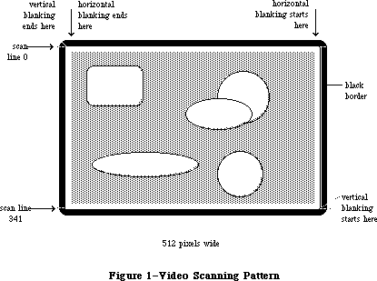 Figure 1–Video Scanning Pattern
A full screen display consists of 342 horizontal scan lines, occupying 15367.65 usec, or about 15.37 milliseconds (msec). The vertical blanking interval takes the time of an additional 28 scan lines—1258.17 usec, or about 1.26 msec. This means the full screen is redisplayed once every 16625.8 usec. That’s about 16.6 msec per frame, which means the vertical scan rate (the full screen display frequency) is 60.15 hertz.
The video generator uses 21,888 bytes of RAM to compose a bit-mapped video image 512 pixels wide by 342 pixels tall. Each bit in this range controls a single pixel in the image: A 0 bit is white, and a 1 bit is black.
There are two screen buffers (areas of memory from which the video circuitry can read information to create a screen display): the main buffer and the alternate buffer. The starting addresses of the screen buffers depend on how much memory you have in your Macintosh. In a Macintosh 128K, the main screen buffer starts at $1A700 and the alternate buffer starts at $12700; for a 512K Macintosh, add $60000 to these numbers.
Warning: To be sure you don’t use the wrong area of memory and to maintain
compatibility with future Macintosh systems, you should get the
video base address and bit map dimensions from screenBits (see
the QuickDraw chapter).
Each scan line of the screen displays the contents of 32 consecutive words of memory, each word controlling 16 horizontally adjacent pixels. In each word, the high-order bit (bit 15) controls the leftmost pixel and the low-order bit
(bit 0) controls the rightmost pixel. The first word in each scan line follows the last word on the line above it. The starting address of the screen is thus in the top left corner, and the addresses progress from there to the right and down, to the last byte in the extreme bottom right corner.
Normally, the video display doesn’t flicker when you read from or write to it, because the video memory accesses are interleaved with the processor accesses. But if you’re creating an animated image by repeatedly drawing the graphics in quick succession, it may appear to flicker if the electron beam displays it when your program hasn’t finished updating it, showing some of the new image and some of the old in the same frame.
One way to prevent flickering when you’re updating the screen continuously is to use the vertical and horizontal blanking signals to synchronize your updates to the scanning of video memory. Small changes to your screen can be completed entirely during the interval between frames (the first 1.26 msec following a vertical blanking interrupt), when nothing is being displayed on the screen. When making larger changes, the trick is to keep your changes happening always ahead of the spot being displayed by the electron beam, as it scans byte by byte through the video memory. Changes you make in the memory already passed over by the scan spot won’t appear until the next frame. If you start changing your image when the vertical blanking interrupt occurs, you have 1.26 msec of unrestricted access to the image. After that, you can change progressively less and less of your image as it’s scanned onto the screen, starting from the top
(the lowest video memory address). From vertical blanking interrupt, you have only 1.26 msec in which to change the first (lowest address) screen location, but you have almost 16.6 msec to change the last (highest address) screen location.
Another way to create smooth, flicker-free graphics, especially useful with changes that may take more 16.6 msec, is to use the two screen buffers as alternate displays. If you draw into the one that’s currently not being displayed, and then switch the buffers during the next vertical blanking, your graphics will change all at once, producing a clean animation. (See the Vertical Retrace Manager chapter to find out how to specify tasks to be performed during vertical blanking.)
If you want to use the alternate screen buffer, you’ll have to specify this to the Segment Loader (see the Segment Loader chapter for details). To switch to the alternate screen buffer, clear the following bit of VIA data register A
(vBase+vBufA):
vPage2 .EQU 6 ;0 = alternate screen buffer
For example:
BCLR #vPage2,vBase+vBufA
To switch back to the main buffer, set the same bit.
Warning: Whenever you change a bit in a VIA data register, be sure to
leave the other bits in the register unchanged.
Warning: The alternate screen buffer may not be supported in future
versions of the Macintosh.
The starting addresses of the Macintosh Plus screen buffers depend on the amount of memory present in the machine. The following table shows the starting address of the main and the alternate screen buffer for various memory configurations of the Macintosh Plus:
System Main Screen Alternate
Macintosh Plus, 1Mb $FA700 $F2700
Macintosh Plus, 2Mb $1FA700 $1F2700
Macintosh Plus, 2.5Mb $27A700 $272700
Macintosh Plus, 4Mb $3FA700 $3F2700
Warning: To ensure that software will run on Macintoshes of different memory
size, as well as on future Macintoshes, use the address stored in
the global variable ScrnBase. Also, the alternate screen buffer may
not be available in future versions of the Macintosh and may not be
found in some software configurations of current Macintoshes.
_______________________________________________________________________________
»THE SOUND GENERATOR
_______________________________________________________________________________
The Macintosh sound circuitry uses a series of values taken from an area of RAM to create a changing waveform in the output signal. This signal drives a small speaker inside the Macintosh and is connected to the external sound jack on the back of the computer. If a plug is inserted into the external sound jack, the internal speaker is disabled. The external sound line can drive a load of 600 or more ohms, such as the input of almost any audio amplifier, but not a directly connected external speaker.
The sound generator may be turned on or off by writing 1 (off) or 0 (on) to the following bit of VIA data register B (vBase+vBufB):
vSndEnb .EQU 7 ;0 = sound enabled, 1 = disabled
For example:
BSET #vSndEnb,vBase+vBufB ;turn off sound
By storing a range of values in the sound buffer, you can create the corresponding waveform in the sound channel. The sound generator uses a form of pulse-width encoding to create sounds. The sound circuitry reads one word in the sound buffer during each horizontal blanking interval (including the
“virtual” intervals during vertical blanking) and uses the high-order byte of the word to generate a pulse of electricity whose duration (width) is proportional to the value in the byte. Another circuit converts this pulse into a voltage that’s attenuated (reduced) by a three-bit value from the VIA. This reduction corresponds to the current setting of the volume level. To set the volume directly, store a three-bit number in the low-order bits of VIA data register A (vBase+vBufA). You can use the following constant to isolate the bits involved:
vSound .EQU 7 ;sound volume bits
Here’s an example of how to set the sound level:
MOVE.B vBase+vBufA,D0 ;get current value of register A
ANDI.B #255-vSound,D0 ;clear the sound bits
ORI.B #3,D0 ;set medium sound level
MOVE.B D0,vBase+vBufA ;put the data back
After attenuation, the sound signal is passed to the audio output line.
The sound circuitry scans the sound buffer at a fixed rate of 370 words per video frame, repeating the full cycle 60.15 times per second. To create sounds with frequencies other than multiples of the basic scan rate, you must store phase-shifted patterns into the sound buffer between each scan. You can use the vertical and horizontal blanking signals (available in the VIA) to synchronize your sound buffer updates to the buffer scan. You may find that it’s much easier to use the routines in the Sound Driver to do these functions.
Warning: The low-order byte of each word in the sound buffer is used to
control the speed of the motor in the disk drive. Don’t store
any information there, or you’ll interfere with the disk I/O.
There are two sound buffers, just as there are two screen buffers. The address of the main sound buffer is stored in the global variable SoundBase and is also available as the constant soundLow. The main sound buffer is at $1FD00 in a 128K Macintosh, and the alternate buffer is at $1A100; for a 512K Macintosh, add $60000 to these values. Each sound buffer contains 370 words of data. As when you want to use the alternate screen buffer, you’ll have to specify to the Segment Loader that you want the alternate buffer (see the Segment Loader chapter for details). To select the alternate sound buffer for output, clear the following bit of VIA data register A (vBase+vBufA):
vSndPg2 .EQU 3 ;0 = alternate sound buffer
To return to the main buffer, set the same bit.
Warning: Be sure to switch back to the main sound buffer before doing a
disk access, or the disk won’t work properly.
Warning: The alternate sound buffer may not be supported in future
versions of the Macintosh.
There’s another way to generate a simple, square-wave tone of any frequency, using almost no processor intervention. To do this, first load a constant value into all 370 sound buffer locations (use $00’s for minumum volume, $FF’s for maximum volume). Next, load a value into the VIA’s timer 1 latches, and set the high-order two bits of the VIA’s auxiliary control register (vBase+vACR) for
“square wave output” from timer 1. The timer will then count down from the latched value at 1.2766 usec/count, over and over, inverting the vSndEnb bit of VIA register B (vBase+vBufB) after each count down. This takes the constant voltage being generated from the sound buffer and turns it on and off, creating a square-wave sound whose period is
2 * 1.2766 usec * timer 1’s latched value
Note: You may want to disable timer 1 interrupts during this process (bit 6
in the VIA’s interrupt enable register, which is at vBase+vIER).
To stop the square-wave sound, reset the high-order two bits of the auxiliary control register.
Note: See the SY6522 technical specifications for details of the VIA
registers. See also “Sound Driver Hardware” in the Sound Driver
chapter.
Figure 2 shows a block diagram for the sound port.
The starting addresses of the Macintosh Plus sound buffers depend on the amount of memory present in the machine. The following table shows the starting address of the main and the alternate sound buffer for various memory configurations of the Macintosh Plus:
System Main Sound Alternate
Macintosh Plus, 1Mb $FFD00 $FA100
Macintosh Plus, 2Mb $1FFD00 $1FA100
Macintosh Plus, 2.5Mb $27FD00 $27A100
Macintosh Plus, 4Mb $3FFD00 $3FA100
Warning: To ensure that software will run on Macintoshes of different memory
size, as well as future Macintoshes, use the address stored in the
global variable SoundBase. Also, the alternate sound buffer may not
be available in future versions of the Macintosh and may not be found
in some software configurations of current Macintoshes.
_______________________________________________________________________________
»THE SCC
_______________________________________________________________________________
The two serial ports are controlled by a Zilog Z8530 Serial Communications Controller (SCC). The port known as SCC port A is the one with the modem icon on the back of the Macintosh. SCC port B is the one with the printer icon.
Macintosh serial ports conform to the EIA standard RS422, which differs from the more common RS232C standard. While RS232C modulates a signal with respect to a common ground (“single-ended” transmission), RS422 modulates two signals against each other (“differential” transmission). The RS232C receiver senses whether the received signal is sufficiently negative with respect to ground to be a logic “1”, whereas the RS422 receiver simply senses which line is more negative than the other. This makes RS422 more immune to noise and interference, and more versatile over longer distances. If you ground the positive side of each RS422 receiver and leave unconnected the positive side of each transmitter, you’ve converted to EIA standard RS423, which can be used to communicate with most RS232C devices over distances up to fifty feet or so.
Figure 1–Video Scanning Pattern
A full screen display consists of 342 horizontal scan lines, occupying 15367.65 usec, or about 15.37 milliseconds (msec). The vertical blanking interval takes the time of an additional 28 scan lines—1258.17 usec, or about 1.26 msec. This means the full screen is redisplayed once every 16625.8 usec. That’s about 16.6 msec per frame, which means the vertical scan rate (the full screen display frequency) is 60.15 hertz.
The video generator uses 21,888 bytes of RAM to compose a bit-mapped video image 512 pixels wide by 342 pixels tall. Each bit in this range controls a single pixel in the image: A 0 bit is white, and a 1 bit is black.
There are two screen buffers (areas of memory from which the video circuitry can read information to create a screen display): the main buffer and the alternate buffer. The starting addresses of the screen buffers depend on how much memory you have in your Macintosh. In a Macintosh 128K, the main screen buffer starts at $1A700 and the alternate buffer starts at $12700; for a 512K Macintosh, add $60000 to these numbers.
Warning: To be sure you don’t use the wrong area of memory and to maintain
compatibility with future Macintosh systems, you should get the
video base address and bit map dimensions from screenBits (see
the QuickDraw chapter).
Each scan line of the screen displays the contents of 32 consecutive words of memory, each word controlling 16 horizontally adjacent pixels. In each word, the high-order bit (bit 15) controls the leftmost pixel and the low-order bit
(bit 0) controls the rightmost pixel. The first word in each scan line follows the last word on the line above it. The starting address of the screen is thus in the top left corner, and the addresses progress from there to the right and down, to the last byte in the extreme bottom right corner.
Normally, the video display doesn’t flicker when you read from or write to it, because the video memory accesses are interleaved with the processor accesses. But if you’re creating an animated image by repeatedly drawing the graphics in quick succession, it may appear to flicker if the electron beam displays it when your program hasn’t finished updating it, showing some of the new image and some of the old in the same frame.
One way to prevent flickering when you’re updating the screen continuously is to use the vertical and horizontal blanking signals to synchronize your updates to the scanning of video memory. Small changes to your screen can be completed entirely during the interval between frames (the first 1.26 msec following a vertical blanking interrupt), when nothing is being displayed on the screen. When making larger changes, the trick is to keep your changes happening always ahead of the spot being displayed by the electron beam, as it scans byte by byte through the video memory. Changes you make in the memory already passed over by the scan spot won’t appear until the next frame. If you start changing your image when the vertical blanking interrupt occurs, you have 1.26 msec of unrestricted access to the image. After that, you can change progressively less and less of your image as it’s scanned onto the screen, starting from the top
(the lowest video memory address). From vertical blanking interrupt, you have only 1.26 msec in which to change the first (lowest address) screen location, but you have almost 16.6 msec to change the last (highest address) screen location.
Another way to create smooth, flicker-free graphics, especially useful with changes that may take more 16.6 msec, is to use the two screen buffers as alternate displays. If you draw into the one that’s currently not being displayed, and then switch the buffers during the next vertical blanking, your graphics will change all at once, producing a clean animation. (See the Vertical Retrace Manager chapter to find out how to specify tasks to be performed during vertical blanking.)
If you want to use the alternate screen buffer, you’ll have to specify this to the Segment Loader (see the Segment Loader chapter for details). To switch to the alternate screen buffer, clear the following bit of VIA data register A
(vBase+vBufA):
vPage2 .EQU 6 ;0 = alternate screen buffer
For example:
BCLR #vPage2,vBase+vBufA
To switch back to the main buffer, set the same bit.
Warning: Whenever you change a bit in a VIA data register, be sure to
leave the other bits in the register unchanged.
Warning: The alternate screen buffer may not be supported in future
versions of the Macintosh.
The starting addresses of the Macintosh Plus screen buffers depend on the amount of memory present in the machine. The following table shows the starting address of the main and the alternate screen buffer for various memory configurations of the Macintosh Plus:
System Main Screen Alternate
Macintosh Plus, 1Mb $FA700 $F2700
Macintosh Plus, 2Mb $1FA700 $1F2700
Macintosh Plus, 2.5Mb $27A700 $272700
Macintosh Plus, 4Mb $3FA700 $3F2700
Warning: To ensure that software will run on Macintoshes of different memory
size, as well as on future Macintoshes, use the address stored in
the global variable ScrnBase. Also, the alternate screen buffer may
not be available in future versions of the Macintosh and may not be
found in some software configurations of current Macintoshes.
_______________________________________________________________________________
»THE SOUND GENERATOR
_______________________________________________________________________________
The Macintosh sound circuitry uses a series of values taken from an area of RAM to create a changing waveform in the output signal. This signal drives a small speaker inside the Macintosh and is connected to the external sound jack on the back of the computer. If a plug is inserted into the external sound jack, the internal speaker is disabled. The external sound line can drive a load of 600 or more ohms, such as the input of almost any audio amplifier, but not a directly connected external speaker.
The sound generator may be turned on or off by writing 1 (off) or 0 (on) to the following bit of VIA data register B (vBase+vBufB):
vSndEnb .EQU 7 ;0 = sound enabled, 1 = disabled
For example:
BSET #vSndEnb,vBase+vBufB ;turn off sound
By storing a range of values in the sound buffer, you can create the corresponding waveform in the sound channel. The sound generator uses a form of pulse-width encoding to create sounds. The sound circuitry reads one word in the sound buffer during each horizontal blanking interval (including the
“virtual” intervals during vertical blanking) and uses the high-order byte of the word to generate a pulse of electricity whose duration (width) is proportional to the value in the byte. Another circuit converts this pulse into a voltage that’s attenuated (reduced) by a three-bit value from the VIA. This reduction corresponds to the current setting of the volume level. To set the volume directly, store a three-bit number in the low-order bits of VIA data register A (vBase+vBufA). You can use the following constant to isolate the bits involved:
vSound .EQU 7 ;sound volume bits
Here’s an example of how to set the sound level:
MOVE.B vBase+vBufA,D0 ;get current value of register A
ANDI.B #255-vSound,D0 ;clear the sound bits
ORI.B #3,D0 ;set medium sound level
MOVE.B D0,vBase+vBufA ;put the data back
After attenuation, the sound signal is passed to the audio output line.
The sound circuitry scans the sound buffer at a fixed rate of 370 words per video frame, repeating the full cycle 60.15 times per second. To create sounds with frequencies other than multiples of the basic scan rate, you must store phase-shifted patterns into the sound buffer between each scan. You can use the vertical and horizontal blanking signals (available in the VIA) to synchronize your sound buffer updates to the buffer scan. You may find that it’s much easier to use the routines in the Sound Driver to do these functions.
Warning: The low-order byte of each word in the sound buffer is used to
control the speed of the motor in the disk drive. Don’t store
any information there, or you’ll interfere with the disk I/O.
There are two sound buffers, just as there are two screen buffers. The address of the main sound buffer is stored in the global variable SoundBase and is also available as the constant soundLow. The main sound buffer is at $1FD00 in a 128K Macintosh, and the alternate buffer is at $1A100; for a 512K Macintosh, add $60000 to these values. Each sound buffer contains 370 words of data. As when you want to use the alternate screen buffer, you’ll have to specify to the Segment Loader that you want the alternate buffer (see the Segment Loader chapter for details). To select the alternate sound buffer for output, clear the following bit of VIA data register A (vBase+vBufA):
vSndPg2 .EQU 3 ;0 = alternate sound buffer
To return to the main buffer, set the same bit.
Warning: Be sure to switch back to the main sound buffer before doing a
disk access, or the disk won’t work properly.
Warning: The alternate sound buffer may not be supported in future
versions of the Macintosh.
There’s another way to generate a simple, square-wave tone of any frequency, using almost no processor intervention. To do this, first load a constant value into all 370 sound buffer locations (use $00’s for minumum volume, $FF’s for maximum volume). Next, load a value into the VIA’s timer 1 latches, and set the high-order two bits of the VIA’s auxiliary control register (vBase+vACR) for
“square wave output” from timer 1. The timer will then count down from the latched value at 1.2766 usec/count, over and over, inverting the vSndEnb bit of VIA register B (vBase+vBufB) after each count down. This takes the constant voltage being generated from the sound buffer and turns it on and off, creating a square-wave sound whose period is
2 * 1.2766 usec * timer 1’s latched value
Note: You may want to disable timer 1 interrupts during this process (bit 6
in the VIA’s interrupt enable register, which is at vBase+vIER).
To stop the square-wave sound, reset the high-order two bits of the auxiliary control register.
Note: See the SY6522 technical specifications for details of the VIA
registers. See also “Sound Driver Hardware” in the Sound Driver
chapter.
Figure 2 shows a block diagram for the sound port.
The starting addresses of the Macintosh Plus sound buffers depend on the amount of memory present in the machine. The following table shows the starting address of the main and the alternate sound buffer for various memory configurations of the Macintosh Plus:
System Main Sound Alternate
Macintosh Plus, 1Mb $FFD00 $FA100
Macintosh Plus, 2Mb $1FFD00 $1FA100
Macintosh Plus, 2.5Mb $27FD00 $27A100
Macintosh Plus, 4Mb $3FFD00 $3FA100
Warning: To ensure that software will run on Macintoshes of different memory
size, as well as future Macintoshes, use the address stored in the
global variable SoundBase. Also, the alternate sound buffer may not
be available in future versions of the Macintosh and may not be found
in some software configurations of current Macintoshes.
_______________________________________________________________________________
»THE SCC
_______________________________________________________________________________
The two serial ports are controlled by a Zilog Z8530 Serial Communications Controller (SCC). The port known as SCC port A is the one with the modem icon on the back of the Macintosh. SCC port B is the one with the printer icon.
Macintosh serial ports conform to the EIA standard RS422, which differs from the more common RS232C standard. While RS232C modulates a signal with respect to a common ground (“single-ended” transmission), RS422 modulates two signals against each other (“differential” transmission). The RS232C receiver senses whether the received signal is sufficiently negative with respect to ground to be a logic “1”, whereas the RS422 receiver simply senses which line is more negative than the other. This makes RS422 more immune to noise and interference, and more versatile over longer distances. If you ground the positive side of each RS422 receiver and leave unconnected the positive side of each transmitter, you’ve converted to EIA standard RS423, which can be used to communicate with most RS232C devices over distances up to fifty feet or so.
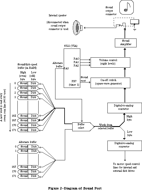 Figure 2–Diagram of Sound Port
The serial inputs and outputs of the SCC are connected to the ports through differential line drivers (26LS30) and receivers (26LS32). The line drivers can be put in the high-impedance mode between transmissions, to allow other devices to transmit over those lines. A driver is activated by lowering the SCC’s Request To Send (RTS) output for that port. Port A and port B are identical except that port A (the modem port) has a higher interrupt priority, making it more suitable for high-speed communication.
Figure 3 shows the DB-9 pinout for the SCC output jacks.
Figure 2–Diagram of Sound Port
The serial inputs and outputs of the SCC are connected to the ports through differential line drivers (26LS30) and receivers (26LS32). The line drivers can be put in the high-impedance mode between transmissions, to allow other devices to transmit over those lines. A driver is activated by lowering the SCC’s Request To Send (RTS) output for that port. Port A and port B are identical except that port A (the modem port) has a higher interrupt priority, making it more suitable for high-speed communication.
Figure 3 shows the DB-9 pinout for the SCC output jacks.
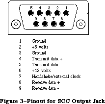 Figure 3–Pinout for SCC Output Jacks
Warning: Do not draw more than 100 milliamps at +12 volts, and
200 milliamps at +5 volts from all connectors combined.
Each port’s input-only handshake line (pin 7) is connected to the SCC’s Clear To Send (CTS) input for that port, and is designed to accept an external
device’s Data Terminal Ready (DTR) handshake signal. This line is also connected to the SCC’s external synchronous clock (TRxC) input for that port, so that an external device can perform high-speed synchronous data exchange. Note that you can’t use the line for receiving DTR if you’re using it to receive a high-speed data clock.
The handshake line is sensed by the Macintosh using the positive (noninverting) input of one of the standard RS422 receivers (26LS32 chip), with the negative input grounded. The positive input was chosen because this configuration is more immune to noise when no active device is connected to pin 7.
Note: Because this is a differential receiver, any handshake or clock signal
driving it must be “bi-polar”, alternating between a positive voltage
and a negative voltage, with respect to the internally grounded negative
input. If a device tries to use ground (0 volts) as one of its handshake
logic levels, the Macintosh will receive that level as an indeterminate
state, with unpredicatbale results.
The SCC itself (at its PCLK pin) is clocked at 3.672 megahertz. The internal synchronous clock (RTxC) pins for both ports are also connected to this 3.672 MHz clock. This is the clock that, after dividing by 16, is normally fed to the SCC’s internal baud-rate generator.
The SCC chip generates level-2 processor interrupts during I/O over the serial lines. For more information about SCC interrupts, see the Device Manager chapter.
The locations of the SCC control and data lines are given in the following table as offsets from the constant sccWBase for writes, or sccRBase for reads. These base addresses are also available in the global variables SCCWr and SCCRd. The SCC is on the upper byte of the data bus, so you must use only even-addressed byte reads (a byte read of an odd SCC read address tries to reset the entire SCC). When writing, however, you must use only odd-addressed byte writes (the MC68000 puts your data on both bytes of the bus, so it works correctly). A word access to any SCC address will shift the phase of the computer’s high-frequency timing by 128 nanoseconds (system software adjusts it correctly during the system startup process).
Location Contents
sccWBase+aData Write data register A
sccRBase+aData Read data register A
sccWBase+bData Write data register B
sccRBase+bData Read data register B
sccWBase+aCtl Write control register A
sccRBase+aCtl Read control register A
sccWBase+bCtl Write control register B
sccRBase+bCtl Read control register B
Warning: Don’t access the SCC chip more often than once every 2.2 usec. The
SCC requires that much time to let its internal lines stabilize.
Refer to the technical specifications of the Zilog Z8530 for the detailed bit maps and control methods (baud rates, protocols, and so on) of the SCC.
Figure 4 shows a circuit diagram for the serial ports.
Figure 3–Pinout for SCC Output Jacks
Warning: Do not draw more than 100 milliamps at +12 volts, and
200 milliamps at +5 volts from all connectors combined.
Each port’s input-only handshake line (pin 7) is connected to the SCC’s Clear To Send (CTS) input for that port, and is designed to accept an external
device’s Data Terminal Ready (DTR) handshake signal. This line is also connected to the SCC’s external synchronous clock (TRxC) input for that port, so that an external device can perform high-speed synchronous data exchange. Note that you can’t use the line for receiving DTR if you’re using it to receive a high-speed data clock.
The handshake line is sensed by the Macintosh using the positive (noninverting) input of one of the standard RS422 receivers (26LS32 chip), with the negative input grounded. The positive input was chosen because this configuration is more immune to noise when no active device is connected to pin 7.
Note: Because this is a differential receiver, any handshake or clock signal
driving it must be “bi-polar”, alternating between a positive voltage
and a negative voltage, with respect to the internally grounded negative
input. If a device tries to use ground (0 volts) as one of its handshake
logic levels, the Macintosh will receive that level as an indeterminate
state, with unpredicatbale results.
The SCC itself (at its PCLK pin) is clocked at 3.672 megahertz. The internal synchronous clock (RTxC) pins for both ports are also connected to this 3.672 MHz clock. This is the clock that, after dividing by 16, is normally fed to the SCC’s internal baud-rate generator.
The SCC chip generates level-2 processor interrupts during I/O over the serial lines. For more information about SCC interrupts, see the Device Manager chapter.
The locations of the SCC control and data lines are given in the following table as offsets from the constant sccWBase for writes, or sccRBase for reads. These base addresses are also available in the global variables SCCWr and SCCRd. The SCC is on the upper byte of the data bus, so you must use only even-addressed byte reads (a byte read of an odd SCC read address tries to reset the entire SCC). When writing, however, you must use only odd-addressed byte writes (the MC68000 puts your data on both bytes of the bus, so it works correctly). A word access to any SCC address will shift the phase of the computer’s high-frequency timing by 128 nanoseconds (system software adjusts it correctly during the system startup process).
Location Contents
sccWBase+aData Write data register A
sccRBase+aData Read data register A
sccWBase+bData Write data register B
sccRBase+bData Read data register B
sccWBase+aCtl Write control register A
sccRBase+aCtl Read control register A
sccWBase+bCtl Write control register B
sccRBase+bCtl Read control register B
Warning: Don’t access the SCC chip more often than once every 2.2 usec. The
SCC requires that much time to let its internal lines stabilize.
Refer to the technical specifications of the Zilog Z8530 for the detailed bit maps and control methods (baud rates, protocols, and so on) of the SCC.
Figure 4 shows a circuit diagram for the serial ports.
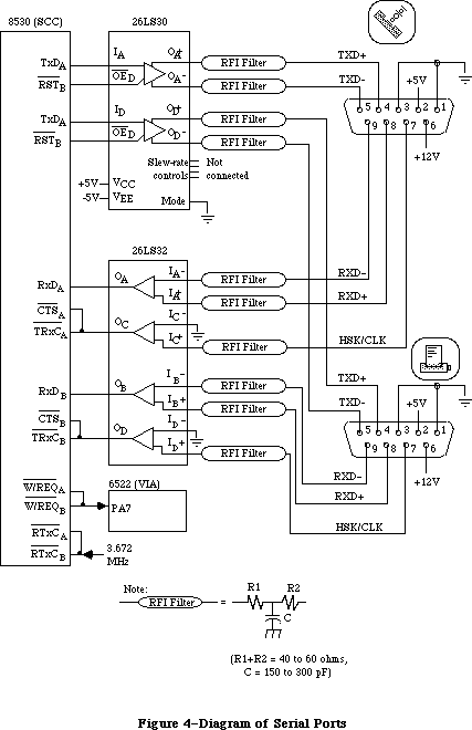 Figure 4–Diagram of Serial Ports
The Macintosh Plus uses two Mini-8 connectors for the two serial ports, replacing the two DB-9 connectors used for the serial ports on the Macintosh 128K, 512K, and 512K enhanced.
The Mini-8 connectors provide an output handshake signal, but do not provide the +5 volts and +12 volts found on the Macintosh 128K, 512K, and 512K enhanced serial ports.
The output handshake signal for each Macintosh Plus serial port originates at the SCC’s Data Terminal Ready (DTR) output for that port, and is driven by an RS423 line driver. Other signals provided include input handshake/external clock, Transmit Data + and –, and Receive Data + and –.
Figure 5 shows the Mini-8 pinout for the SCC serial connectors.
Figure 4–Diagram of Serial Ports
The Macintosh Plus uses two Mini-8 connectors for the two serial ports, replacing the two DB-9 connectors used for the serial ports on the Macintosh 128K, 512K, and 512K enhanced.
The Mini-8 connectors provide an output handshake signal, but do not provide the +5 volts and +12 volts found on the Macintosh 128K, 512K, and 512K enhanced serial ports.
The output handshake signal for each Macintosh Plus serial port originates at the SCC’s Data Terminal Ready (DTR) output for that port, and is driven by an RS423 line driver. Other signals provided include input handshake/external clock, Transmit Data + and –, and Receive Data + and –.
Figure 5 shows the Mini-8 pinout for the SCC serial connectors.
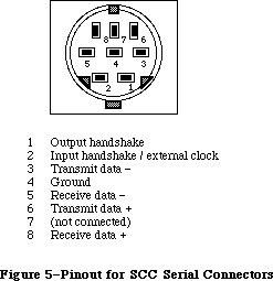 Figure 5–Pinout for SCC Serial Connectors
Figure 6 shows a circuit diagram for the Macintosh Plus serial ports.
Figure 5–Pinout for SCC Serial Connectors
Figure 6 shows a circuit diagram for the Macintosh Plus serial ports.
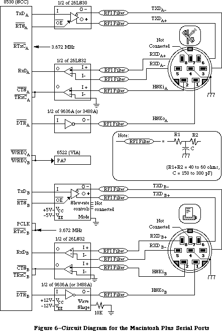 Figure 6–Circuit Diagram for the Macintosh Plus Serial Ports
_______________________________________________________________________________
»THE MOUSE
_______________________________________________________________________________
The DB-9 connector labeled with the mouse icon connects to the Apple mouse
(Apple II, Apple III, Lisa, and Macintosh mice are electrically identical). The mouse generates four square-wave signals that describe the amount and direction of the mouse’s travel. Interrupt-driven routines in the Macintosh ROM convert this information into the corresponding motion of the pointer on the screen. By turning an option called mouse scaling on or off in the Control Panel desk accessory, the user can change the amount of screen pointer motion that corresponds to a given mouse motion, depending on how fast the mouse is moved; for more information about mouse scaling, see the discussion of parameter RAM in the Operating System Utilities chapter.
Note: The mouse is a relative-motion device; that is, it doesn’t report
where it is, only how far and in which direction it’s moving. So if
you want to connect graphics tablets, touch screens, light pens, or
other absolute-position devices to the mouse port, you must either
convert their coordinates into motion information or install your
own device-handling routines.
The mouse operates by sending square-wave trains of information to the Macintosh that change as the velocity and direction of motion change. The rubber-coated steel ball in the mouse contacts two capstans, each connected to an interrupter wheel: Motion along the mouse’s X axis rotates one of the wheels and motion along the Y axis rotates the other wheel.
The Macintosh uses a scheme known as quadrature to detect which direction the mouse is moving along each axis. There’s a row of slots on an interrupter wheel, and two beams of infrared light shine through the slots, each one aimed at a phototransistor detector. The detectors are offset just enough so that, as the wheel turns, they produce two square-wave signals (called the interrupt signal and the quadrature signal) 90 degrees out of phase. The quadrature signal precedes the interrupt signal by 90 degrees when the wheel turns one way, and trails it when the wheel turns the other way.
The interrupt signals, X1 and Y1, are connected to the SCC’s DCDA and DCDB inputs, respectively, while the quadrature signals, X2 and Y2, go to inputs of the VIA’s data register B. When the Macintosh is interrupted (from the SCC) by the rising edge of a mouse interrupt signal, it checks the VIA for the state of the quadrature signal for that axis: If it’s low, the mouse is moving to the left (or down), and if it’s high, the mouse is moving to the right (or up). When the SCC interrupts on the falling edge, a high quadrature level indicates motion to the left (or down) and a low quadrature level indicates motion to the right (or up):
SCC VIA Mouse
Mouse interrupt Mouse quadrature Motion direction in
X1 (or Y1) X2 (or Y2) X (or Y) axis
Positive edge Low Left (or down)
High Right (or up)
Negative edge Low Right (or up)
High Left (or down)
Figure 7 shows the interrupt (Y1) and quadrature (Y2) signals when the mouse is moved downwards.
The switch on the mouse is a pushbutton that grounds pin 7 on the mouse connector when pressed. The state of the button is checked by software during each vertical blanking interrupt. The small delay between each check is sufficient to debounce the button. You can look directly at the mouse button’s state by examining the following bit of VIA data register B (vBase+vBufB):
vSW .EQU 3 ;0 = mouse button is down
If the bit is clear, the mouse button is down. However, it’s recommended that you let the Operating System handle this for you through the event mechanism.
Figure 8 shows the DB-9 pinout for the mouse jack at the back of the Macintosh.
Figure 6–Circuit Diagram for the Macintosh Plus Serial Ports
_______________________________________________________________________________
»THE MOUSE
_______________________________________________________________________________
The DB-9 connector labeled with the mouse icon connects to the Apple mouse
(Apple II, Apple III, Lisa, and Macintosh mice are electrically identical). The mouse generates four square-wave signals that describe the amount and direction of the mouse’s travel. Interrupt-driven routines in the Macintosh ROM convert this information into the corresponding motion of the pointer on the screen. By turning an option called mouse scaling on or off in the Control Panel desk accessory, the user can change the amount of screen pointer motion that corresponds to a given mouse motion, depending on how fast the mouse is moved; for more information about mouse scaling, see the discussion of parameter RAM in the Operating System Utilities chapter.
Note: The mouse is a relative-motion device; that is, it doesn’t report
where it is, only how far and in which direction it’s moving. So if
you want to connect graphics tablets, touch screens, light pens, or
other absolute-position devices to the mouse port, you must either
convert their coordinates into motion information or install your
own device-handling routines.
The mouse operates by sending square-wave trains of information to the Macintosh that change as the velocity and direction of motion change. The rubber-coated steel ball in the mouse contacts two capstans, each connected to an interrupter wheel: Motion along the mouse’s X axis rotates one of the wheels and motion along the Y axis rotates the other wheel.
The Macintosh uses a scheme known as quadrature to detect which direction the mouse is moving along each axis. There’s a row of slots on an interrupter wheel, and two beams of infrared light shine through the slots, each one aimed at a phototransistor detector. The detectors are offset just enough so that, as the wheel turns, they produce two square-wave signals (called the interrupt signal and the quadrature signal) 90 degrees out of phase. The quadrature signal precedes the interrupt signal by 90 degrees when the wheel turns one way, and trails it when the wheel turns the other way.
The interrupt signals, X1 and Y1, are connected to the SCC’s DCDA and DCDB inputs, respectively, while the quadrature signals, X2 and Y2, go to inputs of the VIA’s data register B. When the Macintosh is interrupted (from the SCC) by the rising edge of a mouse interrupt signal, it checks the VIA for the state of the quadrature signal for that axis: If it’s low, the mouse is moving to the left (or down), and if it’s high, the mouse is moving to the right (or up). When the SCC interrupts on the falling edge, a high quadrature level indicates motion to the left (or down) and a low quadrature level indicates motion to the right (or up):
SCC VIA Mouse
Mouse interrupt Mouse quadrature Motion direction in
X1 (or Y1) X2 (or Y2) X (or Y) axis
Positive edge Low Left (or down)
High Right (or up)
Negative edge Low Right (or up)
High Left (or down)
Figure 7 shows the interrupt (Y1) and quadrature (Y2) signals when the mouse is moved downwards.
The switch on the mouse is a pushbutton that grounds pin 7 on the mouse connector when pressed. The state of the button is checked by software during each vertical blanking interrupt. The small delay between each check is sufficient to debounce the button. You can look directly at the mouse button’s state by examining the following bit of VIA data register B (vBase+vBufB):
vSW .EQU 3 ;0 = mouse button is down
If the bit is clear, the mouse button is down. However, it’s recommended that you let the Operating System handle this for you through the event mechanism.
Figure 8 shows the DB-9 pinout for the mouse jack at the back of the Macintosh.
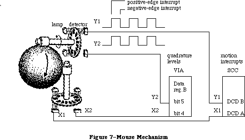 Figure 7–Mouse Mechanism
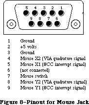 Figure 8–Pinout for Mouse Jack
Warning: Do not draw more than 200 milliamps at +5 volts from all
connectors combined.
Figure 9 shows a circuit diagram for the mouse port.
Figure 8–Pinout for Mouse Jack
Warning: Do not draw more than 200 milliamps at +5 volts from all
connectors combined.
Figure 9 shows a circuit diagram for the mouse port.
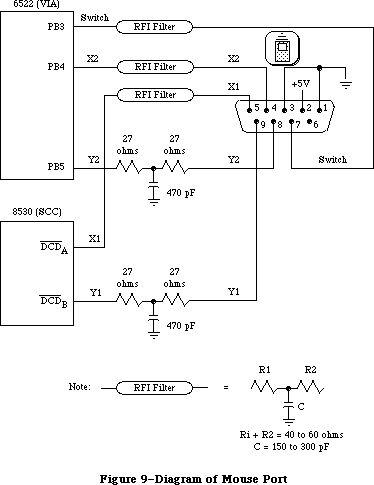 Figure 9–Diagram of Mouse Port
_______________________________________________________________________________
»THE KEYBOARD AND KEYPAD
_______________________________________________________________________________
The Macintosh keyboard and numeric keypad each contain an Intel 8021 microprocessor that scans the keys. The 8021 contains ROM and RAM, and is programmed to conform to the interface protocol described below.
The keyboard plugs into the Macintosh through a four-wire RJ-11 telephone-style jack. If a numeric keypad is installed in the system, the keyboard plugs into it and it in turn plugs into the Macintosh. Figure 10 shows the pinout for the keyboard jack on the Macintosh, on the keyboard itself, and on the numeric keypad.
Figure 9–Diagram of Mouse Port
_______________________________________________________________________________
»THE KEYBOARD AND KEYPAD
_______________________________________________________________________________
The Macintosh keyboard and numeric keypad each contain an Intel 8021 microprocessor that scans the keys. The 8021 contains ROM and RAM, and is programmed to conform to the interface protocol described below.
The keyboard plugs into the Macintosh through a four-wire RJ-11 telephone-style jack. If a numeric keypad is installed in the system, the keyboard plugs into it and it in turn plugs into the Macintosh. Figure 10 shows the pinout for the keyboard jack on the Macintosh, on the keyboard itself, and on the numeric keypad.
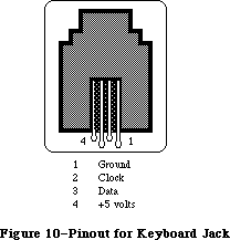 Figure 10–Pinout for Keyboard Jack
Warning: Do not draw more than 200 milliamps at +5 volts from all
connectors combined.
The Macintosh Plus keyboard, which includes a built-in numeric keypad, contains a microprocessor that scans the keys. The microprocessor contains ROM and RAM, and is programmed to conform to the same keyboard interface protocol described below.
The Macintosh Plus keyboard reproduces all of the key-down transitions produced by the keyboard and optional keypad used by the Macintosh 128K, 512K, and 512K enhanced; the Macintosh Plus keyboard is also completely compatible with these other machines. If a key transition occurs for a key that used to be on the optional keypad in lowercase, the Macintosh Plus keyboard still responds to an Inquiry command by sending back the Keypad response ($79) to the Macintosh Plus. If a key transition occurs for an key that used to be on the optional keypad in uppercase, the Macintosh Plus keyboard responds to an Inquiry command by sending back the Shift Key–down Transition response ($71), followed by the Keypad response ($79). The responses for key-down transitions on the original Macintosh and Macintosh Plus are shown (in hexadecimal) in Figure 11.
Figure 10–Pinout for Keyboard Jack
Warning: Do not draw more than 200 milliamps at +5 volts from all
connectors combined.
The Macintosh Plus keyboard, which includes a built-in numeric keypad, contains a microprocessor that scans the keys. The microprocessor contains ROM and RAM, and is programmed to conform to the same keyboard interface protocol described below.
The Macintosh Plus keyboard reproduces all of the key-down transitions produced by the keyboard and optional keypad used by the Macintosh 128K, 512K, and 512K enhanced; the Macintosh Plus keyboard is also completely compatible with these other machines. If a key transition occurs for a key that used to be on the optional keypad in lowercase, the Macintosh Plus keyboard still responds to an Inquiry command by sending back the Keypad response ($79) to the Macintosh Plus. If a key transition occurs for an key that used to be on the optional keypad in uppercase, the Macintosh Plus keyboard responds to an Inquiry command by sending back the Shift Key–down Transition response ($71), followed by the Keypad response ($79). The responses for key-down transitions on the original Macintosh and Macintosh Plus are shown (in hexadecimal) in Figure 11.
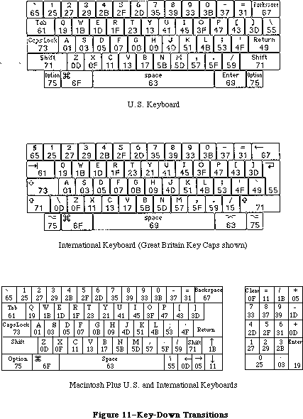 Figure 11–Key-Down Transitions
_______________________________________________________________________________
»Keyboard Communication Protocol
The keyboard data line is bidirectional and is driven by whatever device is sending data. The keyboard clock line is driven by the keyboard only. All data transfers are synchronous with the keyboard clock. Each transmission consists of eight bits, with the highest-order bits first.
When sending data to the Macintosh, the keyboard clock transmits eight 330-usec cycles (160 usec low, 170 usec high) on the normally high clock line. It places the data bit on the data line 40 usec before the falling edge of the clock line and maintains it for 330 usec. The data bit is clocked into the Macintosh’s VIA shift register on the rising edge of the keyboard clock cycle.
When the Macintosh sends data to the keyboard, the keyboard clock transmits eight 400-usec cycles (180 usec low, 220 usec high) on the clock line. On the falling edge of the keyboard clock cycle, the Macintosh places the data bit on the data line and holds it there for 400 usec. The keyboard reads the data bit 80 usec after the rising edge of the keyboard clock cycle.
Only the Macintosh can initiate communication over the keyboard lines. On power-up of either the Macintosh or the keyboard, the Macintosh is in charge, and the external device is passive. The Macintosh signals that it’s ready to begin communication by pulling the keyboard data line low. Upon detecting this, the keyboard starts clocking and the Macintosh sends a command. The last bit of the command leaves the keyboard data line low; the Macintosh then indicates it’s ready to receive the keyboard’s response by setting the data line high.
The first command the Macintosh sends out is the Model Number command. The keyboard’s response to this command is to reset itself and send back its model number to the Macintosh. If no response is received for 1/2 second, the Macintosh tries the Model Number command again. Once the Macintosh has successfully received a model number from the keyboard, normal operation can begin. The Macintosh sends the Inquiry command; the keyboard sends back a Key Transition response if a key has been pressed or released. If no key transition has occurred after 1/4 second, the keyboard sends back a Null response to let the Macintosh know it’s still there. The Macintosh then sends the Inquiry command again. In normal operation, the Macintosh sends out an Inquiry command every 1/4 second. If it receives no response within 1/2 second, it assumes the keyboard is missing or needs resetting, so it begins again with the Model Number command.
There are two other commands the Macintosh can send: the Instant command, which gets an instant keyboard status without the 1/4-second timeout, and the Test command, to perform a keyboard self-test. Here’s a list of the commands that can be sent from the Macintosh to the keyboard:
Command name Value Keyboard response
Inquiry $10 Key Transition code or Null ($7B)
Instant $14 Key Transition code or Null ($7B)
Model Number $16 Bit 0: 1
Bits 1-3: keyboard model number, 1-8
Bits 4-6: next device number, 1-8
Bit 7: 1 if another device connected
Test $36 ACK ($7D) or NAK ($77)
The Key Transition responses are sent out by the keyboard as a single byte: Bit 7 high means a key-up transition, and bit 7 low means a key-down. Bit 0 is always high. The Key Transition responses for key-down transitions on the keyboard are shown (in hexadecimal) in Figure 12. Note that these response codes are different from the key codes returned by the keyboard driver software. The keyboard driver strips off bit 7 of the response and shifts the result one bit to the right, removing bit 0. For example, response code $33 becomes $19, and $2B becomes $15.
_______________________________________________________________________________
»Keypad Communication Protocol
When a numeric keypad is used, it must be inserted between the keyboard and the Macintosh; that is, the keypad cable plugs into the jack on the front of the Macintosh, and the keyboard cable plugs into a jack on the numeric keypad. In this configuration, the timings and protocol for the clock and data lines work a little differently: The keypad acts like a keyboard when communicating with the Macintosh, and acts like a Macintosh when communicating over the separate clock and data lines going to the keyboard. All commands from the Macintosh are now received by the keypad instead of the keyboard, and only the keypad can communicate directly with the keyboard.
When the Macintosh sends out an Inquiry command, one of two things may happen, depending on the state of the keypad. If no key transitions have occurred on the keypad since the last Inquiry, the keypad sends an Inquiry command to the keyboard and, later, retransmits the keyboard’s response back to the Macintosh. But if a key transition has occurred on the keypad, the keypad responds to an Inquiry by sending back the Keypad response ($79) to the Macintosh. In that case, the Macintosh immediately sends an Instant command, and this time the keypad sends back its own Key Transition response. As with the keyboard, bit 7 high means key-up and bit 7 low means key-down.
The Key Transition responses for key-down transitions on the keypad are shown in Figure 12.
Figure 11–Key-Down Transitions
_______________________________________________________________________________
»Keyboard Communication Protocol
The keyboard data line is bidirectional and is driven by whatever device is sending data. The keyboard clock line is driven by the keyboard only. All data transfers are synchronous with the keyboard clock. Each transmission consists of eight bits, with the highest-order bits first.
When sending data to the Macintosh, the keyboard clock transmits eight 330-usec cycles (160 usec low, 170 usec high) on the normally high clock line. It places the data bit on the data line 40 usec before the falling edge of the clock line and maintains it for 330 usec. The data bit is clocked into the Macintosh’s VIA shift register on the rising edge of the keyboard clock cycle.
When the Macintosh sends data to the keyboard, the keyboard clock transmits eight 400-usec cycles (180 usec low, 220 usec high) on the clock line. On the falling edge of the keyboard clock cycle, the Macintosh places the data bit on the data line and holds it there for 400 usec. The keyboard reads the data bit 80 usec after the rising edge of the keyboard clock cycle.
Only the Macintosh can initiate communication over the keyboard lines. On power-up of either the Macintosh or the keyboard, the Macintosh is in charge, and the external device is passive. The Macintosh signals that it’s ready to begin communication by pulling the keyboard data line low. Upon detecting this, the keyboard starts clocking and the Macintosh sends a command. The last bit of the command leaves the keyboard data line low; the Macintosh then indicates it’s ready to receive the keyboard’s response by setting the data line high.
The first command the Macintosh sends out is the Model Number command. The keyboard’s response to this command is to reset itself and send back its model number to the Macintosh. If no response is received for 1/2 second, the Macintosh tries the Model Number command again. Once the Macintosh has successfully received a model number from the keyboard, normal operation can begin. The Macintosh sends the Inquiry command; the keyboard sends back a Key Transition response if a key has been pressed or released. If no key transition has occurred after 1/4 second, the keyboard sends back a Null response to let the Macintosh know it’s still there. The Macintosh then sends the Inquiry command again. In normal operation, the Macintosh sends out an Inquiry command every 1/4 second. If it receives no response within 1/2 second, it assumes the keyboard is missing or needs resetting, so it begins again with the Model Number command.
There are two other commands the Macintosh can send: the Instant command, which gets an instant keyboard status without the 1/4-second timeout, and the Test command, to perform a keyboard self-test. Here’s a list of the commands that can be sent from the Macintosh to the keyboard:
Command name Value Keyboard response
Inquiry $10 Key Transition code or Null ($7B)
Instant $14 Key Transition code or Null ($7B)
Model Number $16 Bit 0: 1
Bits 1-3: keyboard model number, 1-8
Bits 4-6: next device number, 1-8
Bit 7: 1 if another device connected
Test $36 ACK ($7D) or NAK ($77)
The Key Transition responses are sent out by the keyboard as a single byte: Bit 7 high means a key-up transition, and bit 7 low means a key-down. Bit 0 is always high. The Key Transition responses for key-down transitions on the keyboard are shown (in hexadecimal) in Figure 12. Note that these response codes are different from the key codes returned by the keyboard driver software. The keyboard driver strips off bit 7 of the response and shifts the result one bit to the right, removing bit 0. For example, response code $33 becomes $19, and $2B becomes $15.
_______________________________________________________________________________
»Keypad Communication Protocol
When a numeric keypad is used, it must be inserted between the keyboard and the Macintosh; that is, the keypad cable plugs into the jack on the front of the Macintosh, and the keyboard cable plugs into a jack on the numeric keypad. In this configuration, the timings and protocol for the clock and data lines work a little differently: The keypad acts like a keyboard when communicating with the Macintosh, and acts like a Macintosh when communicating over the separate clock and data lines going to the keyboard. All commands from the Macintosh are now received by the keypad instead of the keyboard, and only the keypad can communicate directly with the keyboard.
When the Macintosh sends out an Inquiry command, one of two things may happen, depending on the state of the keypad. If no key transitions have occurred on the keypad since the last Inquiry, the keypad sends an Inquiry command to the keyboard and, later, retransmits the keyboard’s response back to the Macintosh. But if a key transition has occurred on the keypad, the keypad responds to an Inquiry by sending back the Keypad response ($79) to the Macintosh. In that case, the Macintosh immediately sends an Instant command, and this time the keypad sends back its own Key Transition response. As with the keyboard, bit 7 high means key-up and bit 7 low means key-down.
The Key Transition responses for key-down transitions on the keypad are shown in Figure 12.
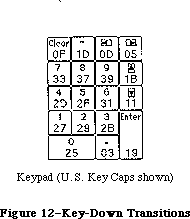 Figure 12–Key-Down Transitions
Again, note that these response codes are different from the key codes returned by the keyboard driver software. The keyboard driver strips off bit 7 of the response and shifts the result one bit to the right, removing bit 0.
_______________________________________________________________________________
»THE FLOPPY DISK INTERFACE
_______________________________________________________________________________
The Macintosh disk interface uses a design similar to that used on the Apple II and Apple III computers, employing the Apple custom IWM chip. Another custom chip called the Analog Signal Generator (ASG) reads the disk speed buffer in RAM and generates voltages that control the disk speed. Together with the VIA, the IWM and the ASG generate all the signals necessary to read, write, format, and eject the 3 1/2-inch disks used by the Macintosh.
The Macintosh Plus has an internal double-sided disk drive; an external double-sided drive or the older single-sided drive, can be attached as well.
Note: The external double-sided drive can be attached to a Macintosh 512K
through the back of a Hard Disk 20. The Hard Disk 20 start-up software
contains a device driver for this drive and the hierarchical (128K ROM)
version of the File Manager.
The double-sided drive can format, read, and write both 800K double-sided disks and 400K single-sided disks. The operation of the drive with double-sided disks differs from that on single-sided disks. With double-sided disks, a single mechanism positions two read/write heads—one above the disk and one below—so that the drive can access two tracks simultaneously—one on the top side, and a second, directly beneath the first, on the bottom side. This lets the drive read or write two complete tracks of information before it has to move the heads, significantly reducing access time. For 400K disks, the double-sided drive restricts itself to one side of the disk.
Warning: Applications (for instance, copy protection schemes) should never
interfere with, or depend on, disk speed control. The double-sided
drive controls its own motor speed, ignoring the speed signal (PWM)
from the Analog Signal Generator (ASG).
The IWM controls four of the disk state-control lines (called CA0, CA1, CA2, and LSTRB), chooses which drive (internal or external) to enable, and processes the disk’s read-data and write-data signals. The VIA provides another disk state-control line called SEL.
A buffer in RAM (actually the low-order bytes of words in the sound buffer) is read by the ASG to generate a pulse-width modulated signal that’s used to control the speed of the disk motor. The Macintosh Operating System uses this speed control to allow it to store more sectors of information in the tracks closer to the edge of the disk by running the disk motor at slower speeds.
Figure 13 shows the DB-19 pinout for the external disk jack at the back of the Macintosh.
Figure 12–Key-Down Transitions
Again, note that these response codes are different from the key codes returned by the keyboard driver software. The keyboard driver strips off bit 7 of the response and shifts the result one bit to the right, removing bit 0.
_______________________________________________________________________________
»THE FLOPPY DISK INTERFACE
_______________________________________________________________________________
The Macintosh disk interface uses a design similar to that used on the Apple II and Apple III computers, employing the Apple custom IWM chip. Another custom chip called the Analog Signal Generator (ASG) reads the disk speed buffer in RAM and generates voltages that control the disk speed. Together with the VIA, the IWM and the ASG generate all the signals necessary to read, write, format, and eject the 3 1/2-inch disks used by the Macintosh.
The Macintosh Plus has an internal double-sided disk drive; an external double-sided drive or the older single-sided drive, can be attached as well.
Note: The external double-sided drive can be attached to a Macintosh 512K
through the back of a Hard Disk 20. The Hard Disk 20 start-up software
contains a device driver for this drive and the hierarchical (128K ROM)
version of the File Manager.
The double-sided drive can format, read, and write both 800K double-sided disks and 400K single-sided disks. The operation of the drive with double-sided disks differs from that on single-sided disks. With double-sided disks, a single mechanism positions two read/write heads—one above the disk and one below—so that the drive can access two tracks simultaneously—one on the top side, and a second, directly beneath the first, on the bottom side. This lets the drive read or write two complete tracks of information before it has to move the heads, significantly reducing access time. For 400K disks, the double-sided drive restricts itself to one side of the disk.
Warning: Applications (for instance, copy protection schemes) should never
interfere with, or depend on, disk speed control. The double-sided
drive controls its own motor speed, ignoring the speed signal (PWM)
from the Analog Signal Generator (ASG).
The IWM controls four of the disk state-control lines (called CA0, CA1, CA2, and LSTRB), chooses which drive (internal or external) to enable, and processes the disk’s read-data and write-data signals. The VIA provides another disk state-control line called SEL.
A buffer in RAM (actually the low-order bytes of words in the sound buffer) is read by the ASG to generate a pulse-width modulated signal that’s used to control the speed of the disk motor. The Macintosh Operating System uses this speed control to allow it to store more sectors of information in the tracks closer to the edge of the disk by running the disk motor at slower speeds.
Figure 13 shows the DB-19 pinout for the external disk jack at the back of the Macintosh.
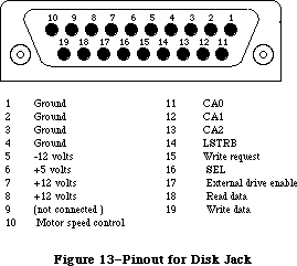 Figure 13–Pinout for Disk Jack
Warning: This connector was designed for a Macintosh 3 1/2-inch disk drive,
which represents a load of 500 milliamps at +12 volts, 500 milliamps
at +5 volts, and 0 milliamps at –12 volts. If any other device uses
this connector, it must not exceed these loads by more than 100
milliamps at +12 volts, 200 milliamps at +5 volts, and 10 milliamps
at –12 volts, including loads from all other connectors combined.
_______________________________________________________________________________
»Controlling the Disk State-Control Lines
The IWM contains registers that can be used by the software to control the state-control lines leading out to the disk. By reading or writing certain memory locations, you can turn these state-control lines on or off. Other locations set various IWM internal states. The locations are given in the following table as offsets from the constant dBase, the base address of the IWM; this base address is also available in a global variable named IWM. The IWM is on the lower byte of the data bus, so use odd-addressed byte accesses only.
Location to Location to
IWM line turn line on turn line off
Disk state-control lines:
CA0 dBase+ph0H dBase+ph0L
CA1 dBase+ph1H dBase+ph1L
CA2 dBase+ph2H dBase+ph2L
LSTRB dBase+ph3H dBase+ph3L
Disk enable line:
ENABLE dBase+motorOn dBase+motorOff
IWM internal states:
SELECT dBase+extDrive dBase+intDrive
Q6 dBase+q6H dBase+q6L
Q7 dBase+q7H dBase+q7L
To turn one of the lines on or off, do any kind of memory byte access (read or write) to the respective location.
The CA0, CA1, and CA2 lines are used along with the SEL line from the VIA to select from among the registers and data signals in the disk drive. The LSTRB line is used when writing control information to the disk registers (as described below), and the ENABLE line enables the selected disk drive. SELECT is an IWM internal line that chooses which disk drive can be enabled: On selects the external drive, and off selects the internal drive. The Q6 and Q7 lines are used to set up the internal state of the IWM for reading disk register information, as well as for reading or writing actual disk-storage data.
You can read information from several registers in the disk drive to find out whether the disk is locked, whether a disk is in the drive, whether the head is at track 0, how many heads the drive has, and whether there’s a drive connected at all. In turn, you can write to some of these registers to step the head, turn the motor on or off, and eject the disk.
_______________________________________________________________________________
»Reading from the Disk Registers
Before you can read from any of the disk registers, you must set up the state of the IWM so that it can pass the data through to the MC68000’s memory space where you’ll be able to read it. To do that, you must first turn off Q7 by reading or writing dBase+q7L. Then turn on Q6 by accessing dBase+q6H. After that, the IWM will be able to pass data from the disk’s RD/SENSE line through to you.
Once you’ve set up the IWM for disk register access, you must next select which register you want to read. To read one of the disk registers, first enable the drive you want to use (by accessing dBase+intDrive or dBase+extDrive and then dBase+motorOn) and make sure LSTRB is low. Then set CA0, CA1, CA2, and SEL to address the register you want. Once this is done, you can read the disk register data bit in the high-order bit of dBase+q7L. After you’ve read the data, you may read another disk register by again setting the proper values in CA0, CA1, CA2, and SEL, and then reading dBase+q7L.
Warning: When you’re finished reading data from the disk registers, it’s
important to leave the IWM in a state that the Disk Driver will
recognize. To be sure it’s in a valid logic state, always turn Q6
back off (by accessing dBase+q6L) after you’ve finished reading
the disk registers.
The Following table shows how you must set the disk state-control lines to read from the various disk registers and data signals:
State-control lines Register
CA2 CA1 CA0 SEL addressed Information in register
0 0 0 0 DIRTN Head step direction
0 0 0 1 CSTIN Disk in place
0 0 1 0 STEP Disk head stepping
0 0 1 1 WRTPRT Disk locked
0 1 0 0 MOTORON Disk motor running
0 1 0 1 TKO Head at track 0
0 1 1 1 TACH Tachometer
1 0 0 0 RDDATA0 Read data, lower head
1 0 0 1 RDDATA1 Read data, upper head
1 1 0 0 SIDES Single- or double-sided drive
1 1 1 1 DRVIN Drive installed
_______________________________________________________________________________
»Writing to the Disk Registers
To write to a disk register, first be sure that LSTRB is off, then turn on CA0 and CA1. Next, set SEL to 0. Set CA0 and CA1 to the proper values from the table below, then set CA2 to the value you want to write to the disk register. Hold LSTRB high for at least one usec but not more than one msec (unless you’re ejecting a disk) and bring it low again. Be sure that you don’t change CA0-CA2 or SEL while LSTRB is high, and that CA0 and CA1 are set high before changing SEL.
The following table shows how you must set the disk state-control lines to write to the various disk registers:
Control lines Register
CA1 CA0 SEL addressed Register function
0 0 0 DIRTN Set stepping direction
0 1 0 STEP Step disk head one track
1 0 0 MOTORON Turn on/off disk motor
1 1 0 EJECT Eject the disk
_______________________________________________________________________________
»Explanations of the Disk Registers
The information written to or read from the various disk registers can be interpreted as follows:
• The DIRTN signal sets the direction of subsequent head stepping:
0 causes steps to go toward the inside track (track 79),
1 causes them to go toward the outside track (track 0).
• CSTIN is 0 only when a disk is in the drive.
• Setting STEP to 0 steps the head one full track in the direction
last set by DIRTN. When the step is complete (about 12 msec), the
disk drive sets STEP back to 1, and then you can step again.
• WRTPRT is 0 whenever the disk is locked. Do not write to a disk
unless WRTPRT is 1.
• MOTORON controls the state of the disk motor: 0 turns on the motor,
and 1 turns it off. The motor will run only if the drive is enabled
and a disk is in place; otherwise, writing to this line will have no
effect.
• TKO goes to 0 only if the head is at track 0. This is valid beginning
12 msec after the step that puts it at track 0.
• Writing 1 to EJECT ejects the disk from the drive. To eject a disk,
you must hold LSTRB high for at least 1/2 second.
• The current disk speed is available as a pulse train on TACH. The TACH
line produces 60 pulses for each rotation of the drive motor. The disk
motor speed is controlled by the ASG as it reads the disk speed RAM buffer.
• RDDATA0 and RDDATA1 carry the instantaneous data from the disk head.
• SIDES is always 0 on single-sided drives and 1 on double-sided drives.
• DRVIN is always 0 if the selected disk drive is physically connected to
the Macintosh, otherwise it floats to 1.
_______________________________________________________________________________
»THE REAL-TIME CLOCK
_______________________________________________________________________________
The Macintosh real-time clock is a custom chip whose interface lines are available through the VIA. The clock contains a four-byte counter that’s incremented once each second, as well as a line that can be used by the VIA to generate an interrupt once each second. It also contains 20 bytes of RAM that are powered by a battery when the Macintosh is turned off. These RAM bytes, called parameter RAM, contain important data that needs to be preserved even when the system power is not available. The Operating System maintains a copy of parameter RAM that you can access in low memory. To find out how to use the values in parameter RAM, see the Operating System Utilities chapter.
The Macintosh Plus real-time clock is a new custom chip. The commands described below for accessing the Macintosh 512K clock chip are also used to access the new chip. The new chip includes additional parameter RAM that’s reserved by Apple. The parameter RAM information provided in the Operating System Utilities chapter, as well as the descriptions of the routines used for accessing that information, apply for the new clock chip as well.
_______________________________________________________________________________
»Accessing the Clock Chip
The clock is accessed through the following bits of VIA data register B
(vBase+vBufB):
rTCData .EQU 0 ;real-time clock serial data line
rTCClk .EQU 1 ;real-time clock data-clock line
rTCEnb .EQU 2 ;real-time clock serial enable
These three bits constitute a simple serial interface. The rTCData bit is a bidirectional serial data line used to send command and data bytes back and forth. The rTCClk bit is a data-clock line, always driven by the processor (you set it high or low yourself) that regulates the transmission of the data and command bits. The rTCEnb bit is the serial enable line, which signals the real-time clock that the processor is about to send it serial commands and data.
To access the clock chip, you must first enable its serial function. To do this, set the serial enable line (rTCEnb) to 0. Keep the serial enable line low during the entire transaction; if you set it to 1, you’ll abort the transfer.
Warning: Be sure you don’t alter any of bits 3-7 of VIA data register
B during clock serial access.
A command can be either a write request or a read request. After the eight bits of a write request, the clock will expect the next eight bits across the serial data line to be your data for storage into one of the internal registers of the clock. After receiving the eight bits of a read request, the clock will respond by putting eight bits of its data on the serial data line. Commands and data are transferred serially in eight-bit groups over the serial data line, with the high-order bit first and the low-order bit last.
To send a command to the clock, first set the rTCData bit of VIA data direction register B (vBase+vDirB) so that the real-time clock’s serial data line will be used for output to the clock. Next, set the rTCClk bit of vBase+vBufB to 0, then set the rTCData bit to the value of the first (high-order) bit of your data byte. Then raise (set to 1) the data-clock bit (rTCClk). Then lower the data-clock, set the serial data line to the next bit, and raise the data-clock line again. After the last bit of your command has been sent in this way, you can either continue by sending your data byte in the same way (if your command was a write request) or switch to receiving a data byte from the clock (if your command was a read request).
To receive a byte of data from the clock, you must first send a command that’s a read request. After you’ve clocked out the last bit of the command, clear the rTCData bit of the data direction register so that the real-time clock’s serial data line can be used for input from the clock; then lower the data-clock bit
(rTCClk) and read the first (high-order) bit of the clock’s data byte on the serial data line. Then raise the data-clock, lower it again, and read the next bit of data. Continue this until all eight bits are read, then raise the serial enable line (rTCEnb), disabling the data transfer.
The following table lists the commands you can send to the clock. A 1 in the high-order bit makes your command a read request; a 0 in the high-order bit makes your command a write request. (In this table, “z” is the bit that determines read or write status, and bits marked “a” are bits whose values depend on what parameter RAM byte you want to address.)
Command byte Register addressed by the command
z0000001 Seconds register 0 (lowest-order byte)
z0000101 Seconds register 1
z0001001 Seconds register 2
z0001101 Seconds register 3 (highest-order byte)
00110001 Test register (write only)
00110101 Write-protect register (write only)
z010aa01 RAM address 100aa ($10-$13)
z1aaaa01 RAM address 0aaaa ($00-$0F)
Note that the last two bits of a command byte must always be 01.
If the high-order bit (bit 7) of the write-protect register is set, this prevents writing into any other register on the clock chip (including parameter RAM). Clearing the bit allows you to change any values in any registers on the chip. Don’t try to read from this register; it’s a write-only register.
The two highest-order bits (bits 7 and 6) of the test register are used as device control bits during testing, and should always be set to 0 during normal operation. Setting them to anything else will interfere with normal clock counting. Like the write-protect register, this is a write-only register; don’t try to read from it.
All clock data must be sent as full eight-bit bytes, even if only one or two bits are of interest. The rest of the bits may not matter, but you must send them to the clock or the write will be aborted when you raise the serial enable line.
It’s important to use the proper sequence if you’re writing to the clock’s seconds registers. If you write to a given seconds register, there’s a chance that the clock may increment the data in the next higher-order register during the write, causing unpredictable results. To avoid this possibility, always write to the registers in low-to-high order. Similarly, the clock data may increment during a read of all four time bytes, which could cause invalid data to be read. To avoid this, always read the time twice (or until you get the same value twice).
Warning: When you’ve finished reading from the clock registers, always end
by doing a final write such as setting the write-protect bit. Failure
to do this may leave the clock in a state that will run down the
battery more quickly than necessary.
_______________________________________________________________________________
»The One-Second Interrupt
The clock also generates a VIA interrupt once each second (if this interrupt is enabled). The enable status for this interrupt can be read from or written to bit 0 of the VIA’s interrupt enable register (vBase+vIER). When reading the enable register, a 1 bit indicates the interrupt is enabled, and 0 means it’s disabled. Writing $01 to the enable register disables the clock’s one-second interrupt (without affecting any other interrupts), while writing $81 enables it again. See the Device Manager chapter for more information about writing your own interrupt handlers.
Warning: Be sure when you write to bit 0 of the VIA’s interrupt enable
register that you don’t change any of the other bits.
_______________________________________________________________________________
»THE SCSI INTERFACE
_______________________________________________________________________________
Note: This section refers to the Macintosh Plus. Earlier Macintosh models
are not equipped with a SCSI interface.
The NCR 5380 Small Computer Standard Interface (SCSI) chip controls a high-speed parallel port for communicating with up to seven SCSI peripherals (such as hard disks, streaming tapes, and high speed printers). The Macintosh Plus SCSI port can be used to implement all of the protocols, arbitration, interconnections, etc. of the SCSI interface as defined by the ANSI X3T9.2 committee.
The Macintosh Plus SCSI port differs from the ANSI X3T9.2 standard in two ways. First, it uses a DB-25 connector instead of the standard 50-pin ribbon connector. An Apple adapter cable, however, can be used to convert the DB-25 connector to the standard 50-pin connector. Second, power for termination resistors is not provided at the SCSI connector nor is a termination resistor provided in the Macintosh Plus SCSI circuitry.
Warning: Do not connect an RS232 device to the SCSI port. The SCSI interface
is designed to use standard TTL logic levels of 0 and +5 volts;
RS232 devices may impose levels of –25 and +25 volts on some lines,
thereby causing damage to the logic board.
The NCR 5380 interrupt signal is not connected to the processor, but the progress of a SCSI operation may be determined at any time by examining the contents of various status registers in the NCR 5380. SCSI data transfers are performed by the MC68000; pseudo-DMA mode operations can assert the NCR 5380 DMA Acknowledge (DACK) signal by reading or writing to the appropriate address
(see table below). Approximate transfer rates are 142K bytes per second for nonblind transfers and 312K bytes per second for blind transfers. (With nonblind transfers, each byte transferred is polled, or checked.)
Figure 14 shows the DB-25 pinout for the SCSI connector at the back of the Macintosh Plus.
Figure 13–Pinout for Disk Jack
Warning: This connector was designed for a Macintosh 3 1/2-inch disk drive,
which represents a load of 500 milliamps at +12 volts, 500 milliamps
at +5 volts, and 0 milliamps at –12 volts. If any other device uses
this connector, it must not exceed these loads by more than 100
milliamps at +12 volts, 200 milliamps at +5 volts, and 10 milliamps
at –12 volts, including loads from all other connectors combined.
_______________________________________________________________________________
»Controlling the Disk State-Control Lines
The IWM contains registers that can be used by the software to control the state-control lines leading out to the disk. By reading or writing certain memory locations, you can turn these state-control lines on or off. Other locations set various IWM internal states. The locations are given in the following table as offsets from the constant dBase, the base address of the IWM; this base address is also available in a global variable named IWM. The IWM is on the lower byte of the data bus, so use odd-addressed byte accesses only.
Location to Location to
IWM line turn line on turn line off
Disk state-control lines:
CA0 dBase+ph0H dBase+ph0L
CA1 dBase+ph1H dBase+ph1L
CA2 dBase+ph2H dBase+ph2L
LSTRB dBase+ph3H dBase+ph3L
Disk enable line:
ENABLE dBase+motorOn dBase+motorOff
IWM internal states:
SELECT dBase+extDrive dBase+intDrive
Q6 dBase+q6H dBase+q6L
Q7 dBase+q7H dBase+q7L
To turn one of the lines on or off, do any kind of memory byte access (read or write) to the respective location.
The CA0, CA1, and CA2 lines are used along with the SEL line from the VIA to select from among the registers and data signals in the disk drive. The LSTRB line is used when writing control information to the disk registers (as described below), and the ENABLE line enables the selected disk drive. SELECT is an IWM internal line that chooses which disk drive can be enabled: On selects the external drive, and off selects the internal drive. The Q6 and Q7 lines are used to set up the internal state of the IWM for reading disk register information, as well as for reading or writing actual disk-storage data.
You can read information from several registers in the disk drive to find out whether the disk is locked, whether a disk is in the drive, whether the head is at track 0, how many heads the drive has, and whether there’s a drive connected at all. In turn, you can write to some of these registers to step the head, turn the motor on or off, and eject the disk.
_______________________________________________________________________________
»Reading from the Disk Registers
Before you can read from any of the disk registers, you must set up the state of the IWM so that it can pass the data through to the MC68000’s memory space where you’ll be able to read it. To do that, you must first turn off Q7 by reading or writing dBase+q7L. Then turn on Q6 by accessing dBase+q6H. After that, the IWM will be able to pass data from the disk’s RD/SENSE line through to you.
Once you’ve set up the IWM for disk register access, you must next select which register you want to read. To read one of the disk registers, first enable the drive you want to use (by accessing dBase+intDrive or dBase+extDrive and then dBase+motorOn) and make sure LSTRB is low. Then set CA0, CA1, CA2, and SEL to address the register you want. Once this is done, you can read the disk register data bit in the high-order bit of dBase+q7L. After you’ve read the data, you may read another disk register by again setting the proper values in CA0, CA1, CA2, and SEL, and then reading dBase+q7L.
Warning: When you’re finished reading data from the disk registers, it’s
important to leave the IWM in a state that the Disk Driver will
recognize. To be sure it’s in a valid logic state, always turn Q6
back off (by accessing dBase+q6L) after you’ve finished reading
the disk registers.
The Following table shows how you must set the disk state-control lines to read from the various disk registers and data signals:
State-control lines Register
CA2 CA1 CA0 SEL addressed Information in register
0 0 0 0 DIRTN Head step direction
0 0 0 1 CSTIN Disk in place
0 0 1 0 STEP Disk head stepping
0 0 1 1 WRTPRT Disk locked
0 1 0 0 MOTORON Disk motor running
0 1 0 1 TKO Head at track 0
0 1 1 1 TACH Tachometer
1 0 0 0 RDDATA0 Read data, lower head
1 0 0 1 RDDATA1 Read data, upper head
1 1 0 0 SIDES Single- or double-sided drive
1 1 1 1 DRVIN Drive installed
_______________________________________________________________________________
»Writing to the Disk Registers
To write to a disk register, first be sure that LSTRB is off, then turn on CA0 and CA1. Next, set SEL to 0. Set CA0 and CA1 to the proper values from the table below, then set CA2 to the value you want to write to the disk register. Hold LSTRB high for at least one usec but not more than one msec (unless you’re ejecting a disk) and bring it low again. Be sure that you don’t change CA0-CA2 or SEL while LSTRB is high, and that CA0 and CA1 are set high before changing SEL.
The following table shows how you must set the disk state-control lines to write to the various disk registers:
Control lines Register
CA1 CA0 SEL addressed Register function
0 0 0 DIRTN Set stepping direction
0 1 0 STEP Step disk head one track
1 0 0 MOTORON Turn on/off disk motor
1 1 0 EJECT Eject the disk
_______________________________________________________________________________
»Explanations of the Disk Registers
The information written to or read from the various disk registers can be interpreted as follows:
• The DIRTN signal sets the direction of subsequent head stepping:
0 causes steps to go toward the inside track (track 79),
1 causes them to go toward the outside track (track 0).
• CSTIN is 0 only when a disk is in the drive.
• Setting STEP to 0 steps the head one full track in the direction
last set by DIRTN. When the step is complete (about 12 msec), the
disk drive sets STEP back to 1, and then you can step again.
• WRTPRT is 0 whenever the disk is locked. Do not write to a disk
unless WRTPRT is 1.
• MOTORON controls the state of the disk motor: 0 turns on the motor,
and 1 turns it off. The motor will run only if the drive is enabled
and a disk is in place; otherwise, writing to this line will have no
effect.
• TKO goes to 0 only if the head is at track 0. This is valid beginning
12 msec after the step that puts it at track 0.
• Writing 1 to EJECT ejects the disk from the drive. To eject a disk,
you must hold LSTRB high for at least 1/2 second.
• The current disk speed is available as a pulse train on TACH. The TACH
line produces 60 pulses for each rotation of the drive motor. The disk
motor speed is controlled by the ASG as it reads the disk speed RAM buffer.
• RDDATA0 and RDDATA1 carry the instantaneous data from the disk head.
• SIDES is always 0 on single-sided drives and 1 on double-sided drives.
• DRVIN is always 0 if the selected disk drive is physically connected to
the Macintosh, otherwise it floats to 1.
_______________________________________________________________________________
»THE REAL-TIME CLOCK
_______________________________________________________________________________
The Macintosh real-time clock is a custom chip whose interface lines are available through the VIA. The clock contains a four-byte counter that’s incremented once each second, as well as a line that can be used by the VIA to generate an interrupt once each second. It also contains 20 bytes of RAM that are powered by a battery when the Macintosh is turned off. These RAM bytes, called parameter RAM, contain important data that needs to be preserved even when the system power is not available. The Operating System maintains a copy of parameter RAM that you can access in low memory. To find out how to use the values in parameter RAM, see the Operating System Utilities chapter.
The Macintosh Plus real-time clock is a new custom chip. The commands described below for accessing the Macintosh 512K clock chip are also used to access the new chip. The new chip includes additional parameter RAM that’s reserved by Apple. The parameter RAM information provided in the Operating System Utilities chapter, as well as the descriptions of the routines used for accessing that information, apply for the new clock chip as well.
_______________________________________________________________________________
»Accessing the Clock Chip
The clock is accessed through the following bits of VIA data register B
(vBase+vBufB):
rTCData .EQU 0 ;real-time clock serial data line
rTCClk .EQU 1 ;real-time clock data-clock line
rTCEnb .EQU 2 ;real-time clock serial enable
These three bits constitute a simple serial interface. The rTCData bit is a bidirectional serial data line used to send command and data bytes back and forth. The rTCClk bit is a data-clock line, always driven by the processor (you set it high or low yourself) that regulates the transmission of the data and command bits. The rTCEnb bit is the serial enable line, which signals the real-time clock that the processor is about to send it serial commands and data.
To access the clock chip, you must first enable its serial function. To do this, set the serial enable line (rTCEnb) to 0. Keep the serial enable line low during the entire transaction; if you set it to 1, you’ll abort the transfer.
Warning: Be sure you don’t alter any of bits 3-7 of VIA data register
B during clock serial access.
A command can be either a write request or a read request. After the eight bits of a write request, the clock will expect the next eight bits across the serial data line to be your data for storage into one of the internal registers of the clock. After receiving the eight bits of a read request, the clock will respond by putting eight bits of its data on the serial data line. Commands and data are transferred serially in eight-bit groups over the serial data line, with the high-order bit first and the low-order bit last.
To send a command to the clock, first set the rTCData bit of VIA data direction register B (vBase+vDirB) so that the real-time clock’s serial data line will be used for output to the clock. Next, set the rTCClk bit of vBase+vBufB to 0, then set the rTCData bit to the value of the first (high-order) bit of your data byte. Then raise (set to 1) the data-clock bit (rTCClk). Then lower the data-clock, set the serial data line to the next bit, and raise the data-clock line again. After the last bit of your command has been sent in this way, you can either continue by sending your data byte in the same way (if your command was a write request) or switch to receiving a data byte from the clock (if your command was a read request).
To receive a byte of data from the clock, you must first send a command that’s a read request. After you’ve clocked out the last bit of the command, clear the rTCData bit of the data direction register so that the real-time clock’s serial data line can be used for input from the clock; then lower the data-clock bit
(rTCClk) and read the first (high-order) bit of the clock’s data byte on the serial data line. Then raise the data-clock, lower it again, and read the next bit of data. Continue this until all eight bits are read, then raise the serial enable line (rTCEnb), disabling the data transfer.
The following table lists the commands you can send to the clock. A 1 in the high-order bit makes your command a read request; a 0 in the high-order bit makes your command a write request. (In this table, “z” is the bit that determines read or write status, and bits marked “a” are bits whose values depend on what parameter RAM byte you want to address.)
Command byte Register addressed by the command
z0000001 Seconds register 0 (lowest-order byte)
z0000101 Seconds register 1
z0001001 Seconds register 2
z0001101 Seconds register 3 (highest-order byte)
00110001 Test register (write only)
00110101 Write-protect register (write only)
z010aa01 RAM address 100aa ($10-$13)
z1aaaa01 RAM address 0aaaa ($00-$0F)
Note that the last two bits of a command byte must always be 01.
If the high-order bit (bit 7) of the write-protect register is set, this prevents writing into any other register on the clock chip (including parameter RAM). Clearing the bit allows you to change any values in any registers on the chip. Don’t try to read from this register; it’s a write-only register.
The two highest-order bits (bits 7 and 6) of the test register are used as device control bits during testing, and should always be set to 0 during normal operation. Setting them to anything else will interfere with normal clock counting. Like the write-protect register, this is a write-only register; don’t try to read from it.
All clock data must be sent as full eight-bit bytes, even if only one or two bits are of interest. The rest of the bits may not matter, but you must send them to the clock or the write will be aborted when you raise the serial enable line.
It’s important to use the proper sequence if you’re writing to the clock’s seconds registers. If you write to a given seconds register, there’s a chance that the clock may increment the data in the next higher-order register during the write, causing unpredictable results. To avoid this possibility, always write to the registers in low-to-high order. Similarly, the clock data may increment during a read of all four time bytes, which could cause invalid data to be read. To avoid this, always read the time twice (or until you get the same value twice).
Warning: When you’ve finished reading from the clock registers, always end
by doing a final write such as setting the write-protect bit. Failure
to do this may leave the clock in a state that will run down the
battery more quickly than necessary.
_______________________________________________________________________________
»The One-Second Interrupt
The clock also generates a VIA interrupt once each second (if this interrupt is enabled). The enable status for this interrupt can be read from or written to bit 0 of the VIA’s interrupt enable register (vBase+vIER). When reading the enable register, a 1 bit indicates the interrupt is enabled, and 0 means it’s disabled. Writing $01 to the enable register disables the clock’s one-second interrupt (without affecting any other interrupts), while writing $81 enables it again. See the Device Manager chapter for more information about writing your own interrupt handlers.
Warning: Be sure when you write to bit 0 of the VIA’s interrupt enable
register that you don’t change any of the other bits.
_______________________________________________________________________________
»THE SCSI INTERFACE
_______________________________________________________________________________
Note: This section refers to the Macintosh Plus. Earlier Macintosh models
are not equipped with a SCSI interface.
The NCR 5380 Small Computer Standard Interface (SCSI) chip controls a high-speed parallel port for communicating with up to seven SCSI peripherals (such as hard disks, streaming tapes, and high speed printers). The Macintosh Plus SCSI port can be used to implement all of the protocols, arbitration, interconnections, etc. of the SCSI interface as defined by the ANSI X3T9.2 committee.
The Macintosh Plus SCSI port differs from the ANSI X3T9.2 standard in two ways. First, it uses a DB-25 connector instead of the standard 50-pin ribbon connector. An Apple adapter cable, however, can be used to convert the DB-25 connector to the standard 50-pin connector. Second, power for termination resistors is not provided at the SCSI connector nor is a termination resistor provided in the Macintosh Plus SCSI circuitry.
Warning: Do not connect an RS232 device to the SCSI port. The SCSI interface
is designed to use standard TTL logic levels of 0 and +5 volts;
RS232 devices may impose levels of –25 and +25 volts on some lines,
thereby causing damage to the logic board.
The NCR 5380 interrupt signal is not connected to the processor, but the progress of a SCSI operation may be determined at any time by examining the contents of various status registers in the NCR 5380. SCSI data transfers are performed by the MC68000; pseudo-DMA mode operations can assert the NCR 5380 DMA Acknowledge (DACK) signal by reading or writing to the appropriate address
(see table below). Approximate transfer rates are 142K bytes per second for nonblind transfers and 312K bytes per second for blind transfers. (With nonblind transfers, each byte transferred is polled, or checked.)
Figure 14 shows the DB-25 pinout for the SCSI connector at the back of the Macintosh Plus.
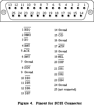 Figure 14–Pinout for SCSI Connector
The locations of the NCR 5380 control and data registers are given in the following table as offsets from the constant scsiWr for write operations, or scsiRd for read operations. These base addresses are not available in global variables; instead of using absolute addresses, you should use the routines provided by the SCSI Manager.
Read and write operations must be made in bytes. Read operations must be to even addresses and write operations must be to odd addresses; otherwise an undefined operation will result.
The address of each register is computed as follows:
$580drn
where r represents the register number (from 0 through 7),
n determines whether it a read or write operation
(0 for reads, or 1 for writes), and
d determines whether the DACK signal to the NCR 5380 is asserted.
(0 for not asserted, 1 is for asserted)
Here’s an example of the address expressed in binary:
0101 1000 0000 00d0 0rrr 000n
Note: Asserting the DACK signal applies only to write operations to
the output data register and read operations from the input
data register.
Symbolic Memory
Location Location NCR 5380 Internal Register
scsiWr+sODR+dackWr $580201 Output Data Register with DACK
scsiRd+sIDR+dackRd $580260 Current SCSI Data with DACK
scsiWr+sODR $580001 Output Data Register
scsiWr+sICR $580011 Initiator Command Register
scsiWr+sMR $580021 Mode Register
scsiWr+sTCR $580031 Target Command Register
scsiWr+sSER $580041 Select Enable Register
scsiWr+sDMAtx $580051 Start DMA Send
scsiWr+sTDMArx $580061 Start DMA Target Receive
scsiWr+sIDMArx $580071 Start DMA Initiator Receive
scsiRd+sCDR $580000 Current SCSI Data
scsiRd+sICR $580010 Initiator Command Register
scsiRd+sMR $580020 Mode Registor
scsiRd+sTCR $580030 Target Command Register
scsiRd+sCSR $580040 Current SCSI Bus Status
scsiRd+sBSR $580050 Bus and Status Register
scsiRd+sIDR $580060 Input Data Register
scsiRd+sRESET $580070 Reset Parity/Interrupt
Note: For more information on the registers and control structure of
the SCSI, consult the technical specifications for the NCR 5380 chip.
_______________________________________________________________________________
»THE VIA
_______________________________________________________________________________
The Synertek SY6522 Versatile Interface Adapter (VIA) controls the keyboard, internal real-time clock, parts of the disk, sound, and mouse interfaces, and various internal Macintosh signals. Its base address is available as the constant vBase and is also stored in a global variable named VIA. The VIA is on the upper byte of the data bus, so use even-addressed byte accesses only.
There are two parallel data registers within the VIA, called A and B, each with a data direction register. There are also several event timers, a clocked shift register, and an interrupt flag register with an interrupt enable register.
Normally you won’t have to touch the direction registers, since the Operating System sets them up for you at system startup. A 1 bit in a data direction register means the corresponding bit of the respective data register will be used for output, while a 0 bit means it will be used for input.
Note: For more information on the registers and control structure of the
VIA, consult the technical specifications for the SY6522 chip.
_______________________________________________________________________________
»VIA Register A
VIA data register A is at vBase+vBufA. The corresponding data direction register is at vBase+vDirA.
Bit(s) Name Description
7 vSCCWReq SCC wait/request
6 vPage2 Alternate screen buffer
5 vHeadSel Disk SEL line
4 vOverlay ROM low-memory overlay
3 vSndPg2 Alternate sound buffer
0-2 vSound (mask) Sound volume
The vSCCWReq bit can signal that the SCC has received a character (used to maintain serial communications during disk accesses, when the CPU’s interrupts from the SCC are disabled). The vPage2 bit controls which screen buffer is being displayed, and the vHeadSel bit is the SEL control line used by the disk interface. The vOverlay bit (used only during system startup) can be used to place another image of ROM at the bottom of memory, where RAM usually is (RAM moves to $600000). The sound buffer is selected by the vSndPg2 bit. Finally, the vSound bits control the sound volume.
_______________________________________________________________________________
»VIA Register B
VIA data register B is at vBase+vBufB. The corresponding data direction register is at vBase+vDirB.
Bit Name Description
7 vSndEnb Sound enable/disable
6 vH4 Horizontal blanking
5 vY2 Mouse Y2
4 vX2 Mouse X2
3 vSW Mouse switch
2 rTCEnb Real-time clock serial enable
1 rTCClk Real-time clock data-clock line
0 rTCData Real-time clock serial data
The vSndEnb bit turns the sound generator on or off, and the vH4 bit is set when the video beam is in its horizontal blanking period. The vY2 and vX2 bits read the quadrature signals from the Y (vertical) and X (horizontal) directions, respectively, of the mouse’s motion lines. The vSW bit reads the mouse switch. The rTCEnb, rTCClk, and rTCData bits control and read the real-time clock.
_______________________________________________________________________________
»The VIA Peripheral Control Register
The VIA’s peripheral control register, at vBase+vPCR, allows you to set some very low-level parameters (such as positive-edge or negative-edge triggering) dealing with the keyboard data and clock interrupts, the one-second real-time clock interrupt line, and the vertical blanking interrupt.
Bit(s) Description
5-7 Keyboard data interrupt control
4 Keyboard clock interrupt control
1-3 One-second interrupt control
0 Vertical blanking interrupt control
_______________________________________________________________________________
»The VIA Timers
The timers controlled by the VIA are called timer 1 and timer 2. Timer 1 is used to time various events having to do with the Macintosh sound generator. Timer 2 is used by the Disk Driver to time disk I/O events. If either timer
isn’t being used by the Operating System, you’re free to use it for your own purposes. When a timer counts down to 0, an interrupt will be generated if the proper interrupt enable has been set. See the Device Manager chapter for information about writing your own interrupt handlers.
To start one of the timers, store the appropriate values in the high- and low-order bytes of the timer counter (or the timer 1 latches, for multiple use of the value). The counters and latches are at the following locations:
Location Contents
vBase+vT1C Timer 1 counter (low-order byte)
vBase+vT1CH Timer 1 counter (high-order byte)
vBase+vT1L Timer 1 latch (low-order byte)
vBase+vT1LH Timer 1 latch (high-order byte)
vBase+vT2C Timer 2 counter (low-order byte)
vBase+vT2CH Timer 2 counter (high-order byte)
Note: When setting a timer, it’s not enough to simply store a full word
to the high-order address, because the high- and low-order bytes of
the counters are not adjacent. You must explicitly do two stores,
one for the high-order byte and one for the low-order byte.
_______________________________________________________________________________
»VIA Interrupts
The VIA (through its IRQ line) can cause a level-1 processor interrupt whenever one of the following occurs: Timer 1 or timer 2 times out; the keyboard is clocking a bit in through its serial port; the shift register for the keyboard serial interface has finished shifting in or out; the vertical blanking interval is beginning; or the one-second clock has ticked. For more information on how to use these interrupts, see the Device Manager chapter.
The interrupt flag register at vBase+vIFR contains flag bits that are set whenever the interrupt corresponding to that bit has occurred. The Operating System uses these flags to determine which device has caused an interrupt. Bit 7 of the interrupt flag register is not really a flag: It remains set (and the IRQ line to the processor is held low) as long as any enabled VIA interrupt is occurring.
Bit Interrupting device
7 IRQ (all enabled VIA interrupts)
6 Timer 1
5 Timer 2
4 Keyboard clock
3 Keyboard data bit
2 Keyboard data ready
1 Vertical blanking interrupt
0 One-second interrupt
The interrupt enable register, at vBase+vIER, lets you enable or disable any of these interrupts. If an interrupt is disabled, its bit in the interrupt flag register will continue to be set whenever that interrupt occurs, but it won’t affect the IRQ flag, nor will it interrupt the processor.
The bits in the interrupt enable register are arranged just like those in the interrupt flag register, except for bit 7. When you write to the interrupt enable register, bit 7 is “enable/disable”: If bit 7 is a 1, each 1 in bits
0-6 enables the corresponding interrupt; if bit 7 is a 0, each 1 in bits 0-6 disables that interrupt. In either case, 0’s in bits 0-6 do not change the status of those interrupts. Bit 7 is always read as a 1.
_______________________________________________________________________________
»Other VIA Registers
The shift register, at vBase+vSR, contains the eight bits of data that have been shifted in or that will be shifted out over the keyboard data line.
The auxiliary control register, at vBase+vACR, is described in the SY6522 documentation. It controls various parameters having to do with the timers and the shift register.
_______________________________________________________________________________
»SYSTEM STARTUP
_______________________________________________________________________________
When power is first supplied to the Macintosh, a carefully orchestrated sequence of events takes place.
First, the processor is held in a wait state while a series of circuits gets the system ready for operation. The VIA and IWM are initialized, and the mapping of ROM and RAM are altered temporarily by setting the overlay bit in VIA data register A. This places the ROM starting at the normal ROM location $400000, and a duplicate image of the same ROM starting at address 0 (where RAM normally is), while RAM is placed starting at $600000. Under this mapping, the Macintosh software executes out of the normal ROM locations above $400000, but the MC68000 can obtain some critical low-memory vectors from the ROM image it finds at address 0.
Next, a memory test and several other system tests take place. After the system is fully tested and initialized, the software clears the VIA’s overlay bit, mapping the system RAM back where it belongs, starting at address 0. Then the disk startup process begins.
First the internal disk is checked: If there’s a disk inserted, the system attempts to read it. If no disk is in the internal drive and there’s an external drive with an inserted disk, the system will try to read that one. Otherwise, the question-mark disk icon is displayed until a disk is inserted. If the disk startup fails for some reason, the “sad Macintosh” icon is displayed and the Macintosh goes into an endless loop until it’s turned off again.
Once a readable disk has been inserted, the first two sectors (containing the system startup blocks) are read in and the normal disk load begins.
_______________________________________________________________________________
»SUMMARY OF THE MACINTOSH HARDWARE
_______________________________________________________________________________
Warning: This information applies only to the Macintosh 128K, 512K,
not to the Macintosh XL.
Constants
; VIA base addresses
vBase .EQU $EFE1FE ;main base for VIA chip (in variable VIA)
aVBufB .EQU vBase ;register B base
aVBufA .EQU $EFFFFE ;register A base
aVBufM .EQU aVBufB ;register containing mouse signals
aVIFR .EQU $EFFBFE ;interrupt flag register
aVIER .EQU $EFFDFE ;interrupt enable register
; Offsets from vBase
vBufB .EQU 512*0 ;register B (zero offset)
vDirB .EQU 512*2 ;register B direction register
vDirA .EQU 512*3 ;register A direction register
vT1C .EQU 512*4 ;timer 1 counter (low-order byte)
vT1CH .EQU 512*5 ;timer 1 counter (high-order byte)
vT1L .EQU 512*6 ;timer 1 latch (low-order byte)
vT1LH .EQU 512*7 ;timer 1 latch (high-order byte)
vT2C .EQU 512*8 ;timer 2 counter (low-order byte)
vT2CH .EQU 512*9 ;timer 2 counter (high-order byte)
vSR .EQU 512*10 ;shift register (keyboard)
vACR .EQU 512*11 ;auxiliary control register
vPCR .EQU 512*12 ;peripheral control register
vIFR .EQU 512*13 ;interrupt flag register
vIER .EQU 512*14 ;interrupt enable register
vBufA .EQU 512*15 ;register A
; VIA register A constants
vAOut .EQU $7F ;direction register A: 1 bits = outputs
vAInit .EQU $7B ;initial value for vBufA (medium volume)
vSound .EQU 7 ;sound volume bits
; VIA register A bit numbers
vSndPg2 .EQU 3 ;0 = alternate sound buffer
vOverlay .EQU 4 ;1 = ROM overlay (system startup only)
vHeadSel .EQU 5 ;disk SEL control line
vPage2 .EQU 6 ;0 = alternate screen buffer
vSCCWReq .EQU 7 ;SCC wait/request line
; VIA register B constants
vBOut .EQU $87 ;direction register B: 1 bits = outputs
vBInit .EQU $07 ;initial value for vBufB
; VIA register B bit numbers
rTCData .EQU 0 ;real-time clock serial data line
rTCClk .EQU 1 ;real-time clock data-clock line
rTCEnb .EQU 2 ;real-time clock serial enable
vSW .EQU 3 ;0 = mouse button is down
vX2 .EQU 4 ;mouse X quadrature level
vY2 .EQU 5 ;mouse Y quadrature level
vH4 .EQU 6 ;1 = horizontal blanking
vSndEnb .EQU 7 ;0 = sound enabled, 1 = disabled
; SCC base addresses
sccRBase .EQU $9FFFF8 ;SCC base read address (in variable SCCRd)
sccWBase .EQU $BFFFF9 ;SCC base write address (in variable SCCWr)
; Offsets from SCC base addresses
aData .EQU 6 ;channel A data in or out
aCtl .EQU 2 ;channel A control
bData .EQU 4 ;channel B data in or out
bCtl .EQU 0 ;channel B control
; Bit numbers for control register RR0
rxBF .EQU 0 ;1 = SCC receive buffer full
txBE .EQU 2 ;1 = SCC send buffer empty
; IWM base address
dBase .EQU $DFE1FF ;IWM base address (in variable IWM)
; Offsets from dBase
ph0L .EQU 512*0 ;CA0 off (0)
ph0H .EQU 512*1 ;CA0 on (1)
ph1L .EQU 512*2 ;CA1 off (0)
ph1H .EQU 512*3 ;CA1 on (1)
ph2L .EQU 512*4 ;CA2 off (0)
ph2H .EQU 512*5 ;CA2 on (1)
ph3L .EQU 512*6 ;LSTRB off (low)
ph3H .EQU 512*7 ;LSTRB on (high)
mtrOff .EQU 512*8 ;disk enable off
mtrOn .EQU 512*9 ;disk enable on
intDrive .EQU 512*10 ;select internal drive
extDrive .EQU 512*11 ;select external drive
q6L .EQU 512*12 ;Q6 off
q6H .EQU 512*13 ;Q6 on
q7L .EQU 512*14 ;Q7 off
q7H .EQU 512*15 ;Q7 on
; Screen and sound addresses for 512K Macintosh (will also work
; for 128K, since addresses wrap)
screenLow .EQU $7A700 ;top left corner of main screen buffer
soundLow .EQU $7FD00 ;main sound buffer (in variable SoundBase)
pwmBuffer .EQU $7FD01 ;main disk speed buffer
ovlyRAM .EQU $600000 ;RAM start address when overlay is set
ovlyScreen .EQU $67A700 ;screen start with overlay set
romStart .EQU $400000 ;ROM start address (in variable ROMBase)
Constants (Macintosh Plus Only)
; SCSI base addresses
scsiRd .EQU $580000 ;base address for read operations
scsiWr .EQU $580001 ;base address for write operations
; SCSI offsets for DACK
dackRd .EQU $200 ;for use with sOCR and sIDR
dackWr .EQU $200 ;for use with sOCR and sIDR
; SCSI offsets to NCR 5380 register
sCDR .EQU $00 ;Current SCSI Read Data (read)
sOCR .EQU $00 ;Output Data Register (write)
sICR .EQU $10 ;Initiator Command Register (read/write)
sMR .EQU $20 ;Mode Register (read/write)
sTCR .EQU $30 ;Target Command Register (read/write)
sCSR .EQU $40 ;Current SCSI Bus Status (read)
sSER .EQU $40 ;Select Enable Register (write)
sBSR .EQU $50 ;Bus & Status Register (read)
sDMAtx .EQU $50 ;DMA Transmit Start (write)
sIDR .EQU $60 ;Data input register (read)
sTDMArx .EQU $60 ;Start Target DMA receive (write)
sRESET .EQU $70 ;Reset Parity/Interrupt (read)
sIDMArx .EQU $70 ;Start Initiator DMA receive (write)
_______________________________________________________________________________
Variables
ROMBase Base address of ROM
SoundBase Address of main sound buffer
SCCRd SCC read base address
SCCWr SCC write base address
IWM IWM base address
VIA VIA base address
_______________________________________________________________________________
Exception Vectors
Location Purpose
$00 Reset: initial stack pointer (not a vector)
$04 Reset: initial vector
$08 Bus error
$0C Address error
$10 Illegal instruction
$14 Divide by zero
$18 CHK instruction
$1C TRAPV instruction
$20 Privilege violation
$24 Trace interrupt
$28 Line 1010 emulator
$2C Line 1111 emulator
$30-$3B Unassigned (reserved)
$3C Uninitialized interrupt
$40-$5F Unassigned (reserved)
$60 Spurious interrupt
$64 VIA interrupt
$68 SCC interrupt
$6C VIA+SCC vector (temporary)
$70 Interrupt switch
$74 Interrupt switch + VIA
$78 Interrupt switch + SCC
$7C Interrupt switch + VIA + SCC
$80-$BF TRAP instructions
$C0-$FF Unassigned (reserved)
Further Reference:
_______________________________________________________________________________
Device Manager
SCSI Manager
Vertical Retrace Manager
“Macintosh Family Hardware Reference”
“Designing Cards and Drivers for the Macintosh II and Macintosh SE”
Figure 14–Pinout for SCSI Connector
The locations of the NCR 5380 control and data registers are given in the following table as offsets from the constant scsiWr for write operations, or scsiRd for read operations. These base addresses are not available in global variables; instead of using absolute addresses, you should use the routines provided by the SCSI Manager.
Read and write operations must be made in bytes. Read operations must be to even addresses and write operations must be to odd addresses; otherwise an undefined operation will result.
The address of each register is computed as follows:
$580drn
where r represents the register number (from 0 through 7),
n determines whether it a read or write operation
(0 for reads, or 1 for writes), and
d determines whether the DACK signal to the NCR 5380 is asserted.
(0 for not asserted, 1 is for asserted)
Here’s an example of the address expressed in binary:
0101 1000 0000 00d0 0rrr 000n
Note: Asserting the DACK signal applies only to write operations to
the output data register and read operations from the input
data register.
Symbolic Memory
Location Location NCR 5380 Internal Register
scsiWr+sODR+dackWr $580201 Output Data Register with DACK
scsiRd+sIDR+dackRd $580260 Current SCSI Data with DACK
scsiWr+sODR $580001 Output Data Register
scsiWr+sICR $580011 Initiator Command Register
scsiWr+sMR $580021 Mode Register
scsiWr+sTCR $580031 Target Command Register
scsiWr+sSER $580041 Select Enable Register
scsiWr+sDMAtx $580051 Start DMA Send
scsiWr+sTDMArx $580061 Start DMA Target Receive
scsiWr+sIDMArx $580071 Start DMA Initiator Receive
scsiRd+sCDR $580000 Current SCSI Data
scsiRd+sICR $580010 Initiator Command Register
scsiRd+sMR $580020 Mode Registor
scsiRd+sTCR $580030 Target Command Register
scsiRd+sCSR $580040 Current SCSI Bus Status
scsiRd+sBSR $580050 Bus and Status Register
scsiRd+sIDR $580060 Input Data Register
scsiRd+sRESET $580070 Reset Parity/Interrupt
Note: For more information on the registers and control structure of
the SCSI, consult the technical specifications for the NCR 5380 chip.
_______________________________________________________________________________
»THE VIA
_______________________________________________________________________________
The Synertek SY6522 Versatile Interface Adapter (VIA) controls the keyboard, internal real-time clock, parts of the disk, sound, and mouse interfaces, and various internal Macintosh signals. Its base address is available as the constant vBase and is also stored in a global variable named VIA. The VIA is on the upper byte of the data bus, so use even-addressed byte accesses only.
There are two parallel data registers within the VIA, called A and B, each with a data direction register. There are also several event timers, a clocked shift register, and an interrupt flag register with an interrupt enable register.
Normally you won’t have to touch the direction registers, since the Operating System sets them up for you at system startup. A 1 bit in a data direction register means the corresponding bit of the respective data register will be used for output, while a 0 bit means it will be used for input.
Note: For more information on the registers and control structure of the
VIA, consult the technical specifications for the SY6522 chip.
_______________________________________________________________________________
»VIA Register A
VIA data register A is at vBase+vBufA. The corresponding data direction register is at vBase+vDirA.
Bit(s) Name Description
7 vSCCWReq SCC wait/request
6 vPage2 Alternate screen buffer
5 vHeadSel Disk SEL line
4 vOverlay ROM low-memory overlay
3 vSndPg2 Alternate sound buffer
0-2 vSound (mask) Sound volume
The vSCCWReq bit can signal that the SCC has received a character (used to maintain serial communications during disk accesses, when the CPU’s interrupts from the SCC are disabled). The vPage2 bit controls which screen buffer is being displayed, and the vHeadSel bit is the SEL control line used by the disk interface. The vOverlay bit (used only during system startup) can be used to place another image of ROM at the bottom of memory, where RAM usually is (RAM moves to $600000). The sound buffer is selected by the vSndPg2 bit. Finally, the vSound bits control the sound volume.
_______________________________________________________________________________
»VIA Register B
VIA data register B is at vBase+vBufB. The corresponding data direction register is at vBase+vDirB.
Bit Name Description
7 vSndEnb Sound enable/disable
6 vH4 Horizontal blanking
5 vY2 Mouse Y2
4 vX2 Mouse X2
3 vSW Mouse switch
2 rTCEnb Real-time clock serial enable
1 rTCClk Real-time clock data-clock line
0 rTCData Real-time clock serial data
The vSndEnb bit turns the sound generator on or off, and the vH4 bit is set when the video beam is in its horizontal blanking period. The vY2 and vX2 bits read the quadrature signals from the Y (vertical) and X (horizontal) directions, respectively, of the mouse’s motion lines. The vSW bit reads the mouse switch. The rTCEnb, rTCClk, and rTCData bits control and read the real-time clock.
_______________________________________________________________________________
»The VIA Peripheral Control Register
The VIA’s peripheral control register, at vBase+vPCR, allows you to set some very low-level parameters (such as positive-edge or negative-edge triggering) dealing with the keyboard data and clock interrupts, the one-second real-time clock interrupt line, and the vertical blanking interrupt.
Bit(s) Description
5-7 Keyboard data interrupt control
4 Keyboard clock interrupt control
1-3 One-second interrupt control
0 Vertical blanking interrupt control
_______________________________________________________________________________
»The VIA Timers
The timers controlled by the VIA are called timer 1 and timer 2. Timer 1 is used to time various events having to do with the Macintosh sound generator. Timer 2 is used by the Disk Driver to time disk I/O events. If either timer
isn’t being used by the Operating System, you’re free to use it for your own purposes. When a timer counts down to 0, an interrupt will be generated if the proper interrupt enable has been set. See the Device Manager chapter for information about writing your own interrupt handlers.
To start one of the timers, store the appropriate values in the high- and low-order bytes of the timer counter (or the timer 1 latches, for multiple use of the value). The counters and latches are at the following locations:
Location Contents
vBase+vT1C Timer 1 counter (low-order byte)
vBase+vT1CH Timer 1 counter (high-order byte)
vBase+vT1L Timer 1 latch (low-order byte)
vBase+vT1LH Timer 1 latch (high-order byte)
vBase+vT2C Timer 2 counter (low-order byte)
vBase+vT2CH Timer 2 counter (high-order byte)
Note: When setting a timer, it’s not enough to simply store a full word
to the high-order address, because the high- and low-order bytes of
the counters are not adjacent. You must explicitly do two stores,
one for the high-order byte and one for the low-order byte.
_______________________________________________________________________________
»VIA Interrupts
The VIA (through its IRQ line) can cause a level-1 processor interrupt whenever one of the following occurs: Timer 1 or timer 2 times out; the keyboard is clocking a bit in through its serial port; the shift register for the keyboard serial interface has finished shifting in or out; the vertical blanking interval is beginning; or the one-second clock has ticked. For more information on how to use these interrupts, see the Device Manager chapter.
The interrupt flag register at vBase+vIFR contains flag bits that are set whenever the interrupt corresponding to that bit has occurred. The Operating System uses these flags to determine which device has caused an interrupt. Bit 7 of the interrupt flag register is not really a flag: It remains set (and the IRQ line to the processor is held low) as long as any enabled VIA interrupt is occurring.
Bit Interrupting device
7 IRQ (all enabled VIA interrupts)
6 Timer 1
5 Timer 2
4 Keyboard clock
3 Keyboard data bit
2 Keyboard data ready
1 Vertical blanking interrupt
0 One-second interrupt
The interrupt enable register, at vBase+vIER, lets you enable or disable any of these interrupts. If an interrupt is disabled, its bit in the interrupt flag register will continue to be set whenever that interrupt occurs, but it won’t affect the IRQ flag, nor will it interrupt the processor.
The bits in the interrupt enable register are arranged just like those in the interrupt flag register, except for bit 7. When you write to the interrupt enable register, bit 7 is “enable/disable”: If bit 7 is a 1, each 1 in bits
0-6 enables the corresponding interrupt; if bit 7 is a 0, each 1 in bits 0-6 disables that interrupt. In either case, 0’s in bits 0-6 do not change the status of those interrupts. Bit 7 is always read as a 1.
_______________________________________________________________________________
»Other VIA Registers
The shift register, at vBase+vSR, contains the eight bits of data that have been shifted in or that will be shifted out over the keyboard data line.
The auxiliary control register, at vBase+vACR, is described in the SY6522 documentation. It controls various parameters having to do with the timers and the shift register.
_______________________________________________________________________________
»SYSTEM STARTUP
_______________________________________________________________________________
When power is first supplied to the Macintosh, a carefully orchestrated sequence of events takes place.
First, the processor is held in a wait state while a series of circuits gets the system ready for operation. The VIA and IWM are initialized, and the mapping of ROM and RAM are altered temporarily by setting the overlay bit in VIA data register A. This places the ROM starting at the normal ROM location $400000, and a duplicate image of the same ROM starting at address 0 (where RAM normally is), while RAM is placed starting at $600000. Under this mapping, the Macintosh software executes out of the normal ROM locations above $400000, but the MC68000 can obtain some critical low-memory vectors from the ROM image it finds at address 0.
Next, a memory test and several other system tests take place. After the system is fully tested and initialized, the software clears the VIA’s overlay bit, mapping the system RAM back where it belongs, starting at address 0. Then the disk startup process begins.
First the internal disk is checked: If there’s a disk inserted, the system attempts to read it. If no disk is in the internal drive and there’s an external drive with an inserted disk, the system will try to read that one. Otherwise, the question-mark disk icon is displayed until a disk is inserted. If the disk startup fails for some reason, the “sad Macintosh” icon is displayed and the Macintosh goes into an endless loop until it’s turned off again.
Once a readable disk has been inserted, the first two sectors (containing the system startup blocks) are read in and the normal disk load begins.
_______________________________________________________________________________
»SUMMARY OF THE MACINTOSH HARDWARE
_______________________________________________________________________________
Warning: This information applies only to the Macintosh 128K, 512K,
not to the Macintosh XL.
Constants
; VIA base addresses
vBase .EQU $EFE1FE ;main base for VIA chip (in variable VIA)
aVBufB .EQU vBase ;register B base
aVBufA .EQU $EFFFFE ;register A base
aVBufM .EQU aVBufB ;register containing mouse signals
aVIFR .EQU $EFFBFE ;interrupt flag register
aVIER .EQU $EFFDFE ;interrupt enable register
; Offsets from vBase
vBufB .EQU 512*0 ;register B (zero offset)
vDirB .EQU 512*2 ;register B direction register
vDirA .EQU 512*3 ;register A direction register
vT1C .EQU 512*4 ;timer 1 counter (low-order byte)
vT1CH .EQU 512*5 ;timer 1 counter (high-order byte)
vT1L .EQU 512*6 ;timer 1 latch (low-order byte)
vT1LH .EQU 512*7 ;timer 1 latch (high-order byte)
vT2C .EQU 512*8 ;timer 2 counter (low-order byte)
vT2CH .EQU 512*9 ;timer 2 counter (high-order byte)
vSR .EQU 512*10 ;shift register (keyboard)
vACR .EQU 512*11 ;auxiliary control register
vPCR .EQU 512*12 ;peripheral control register
vIFR .EQU 512*13 ;interrupt flag register
vIER .EQU 512*14 ;interrupt enable register
vBufA .EQU 512*15 ;register A
; VIA register A constants
vAOut .EQU $7F ;direction register A: 1 bits = outputs
vAInit .EQU $7B ;initial value for vBufA (medium volume)
vSound .EQU 7 ;sound volume bits
; VIA register A bit numbers
vSndPg2 .EQU 3 ;0 = alternate sound buffer
vOverlay .EQU 4 ;1 = ROM overlay (system startup only)
vHeadSel .EQU 5 ;disk SEL control line
vPage2 .EQU 6 ;0 = alternate screen buffer
vSCCWReq .EQU 7 ;SCC wait/request line
; VIA register B constants
vBOut .EQU $87 ;direction register B: 1 bits = outputs
vBInit .EQU $07 ;initial value for vBufB
; VIA register B bit numbers
rTCData .EQU 0 ;real-time clock serial data line
rTCClk .EQU 1 ;real-time clock data-clock line
rTCEnb .EQU 2 ;real-time clock serial enable
vSW .EQU 3 ;0 = mouse button is down
vX2 .EQU 4 ;mouse X quadrature level
vY2 .EQU 5 ;mouse Y quadrature level
vH4 .EQU 6 ;1 = horizontal blanking
vSndEnb .EQU 7 ;0 = sound enabled, 1 = disabled
; SCC base addresses
sccRBase .EQU $9FFFF8 ;SCC base read address (in variable SCCRd)
sccWBase .EQU $BFFFF9 ;SCC base write address (in variable SCCWr)
; Offsets from SCC base addresses
aData .EQU 6 ;channel A data in or out
aCtl .EQU 2 ;channel A control
bData .EQU 4 ;channel B data in or out
bCtl .EQU 0 ;channel B control
; Bit numbers for control register RR0
rxBF .EQU 0 ;1 = SCC receive buffer full
txBE .EQU 2 ;1 = SCC send buffer empty
; IWM base address
dBase .EQU $DFE1FF ;IWM base address (in variable IWM)
; Offsets from dBase
ph0L .EQU 512*0 ;CA0 off (0)
ph0H .EQU 512*1 ;CA0 on (1)
ph1L .EQU 512*2 ;CA1 off (0)
ph1H .EQU 512*3 ;CA1 on (1)
ph2L .EQU 512*4 ;CA2 off (0)
ph2H .EQU 512*5 ;CA2 on (1)
ph3L .EQU 512*6 ;LSTRB off (low)
ph3H .EQU 512*7 ;LSTRB on (high)
mtrOff .EQU 512*8 ;disk enable off
mtrOn .EQU 512*9 ;disk enable on
intDrive .EQU 512*10 ;select internal drive
extDrive .EQU 512*11 ;select external drive
q6L .EQU 512*12 ;Q6 off
q6H .EQU 512*13 ;Q6 on
q7L .EQU 512*14 ;Q7 off
q7H .EQU 512*15 ;Q7 on
; Screen and sound addresses for 512K Macintosh (will also work
; for 128K, since addresses wrap)
screenLow .EQU $7A700 ;top left corner of main screen buffer
soundLow .EQU $7FD00 ;main sound buffer (in variable SoundBase)
pwmBuffer .EQU $7FD01 ;main disk speed buffer
ovlyRAM .EQU $600000 ;RAM start address when overlay is set
ovlyScreen .EQU $67A700 ;screen start with overlay set
romStart .EQU $400000 ;ROM start address (in variable ROMBase)
Constants (Macintosh Plus Only)
; SCSI base addresses
scsiRd .EQU $580000 ;base address for read operations
scsiWr .EQU $580001 ;base address for write operations
; SCSI offsets for DACK
dackRd .EQU $200 ;for use with sOCR and sIDR
dackWr .EQU $200 ;for use with sOCR and sIDR
; SCSI offsets to NCR 5380 register
sCDR .EQU $00 ;Current SCSI Read Data (read)
sOCR .EQU $00 ;Output Data Register (write)
sICR .EQU $10 ;Initiator Command Register (read/write)
sMR .EQU $20 ;Mode Register (read/write)
sTCR .EQU $30 ;Target Command Register (read/write)
sCSR .EQU $40 ;Current SCSI Bus Status (read)
sSER .EQU $40 ;Select Enable Register (write)
sBSR .EQU $50 ;Bus & Status Register (read)
sDMAtx .EQU $50 ;DMA Transmit Start (write)
sIDR .EQU $60 ;Data input register (read)
sTDMArx .EQU $60 ;Start Target DMA receive (write)
sRESET .EQU $70 ;Reset Parity/Interrupt (read)
sIDMArx .EQU $70 ;Start Initiator DMA receive (write)
_______________________________________________________________________________
Variables
ROMBase Base address of ROM
SoundBase Address of main sound buffer
SCCRd SCC read base address
SCCWr SCC write base address
IWM IWM base address
VIA VIA base address
_______________________________________________________________________________
Exception Vectors
Location Purpose
$00 Reset: initial stack pointer (not a vector)
$04 Reset: initial vector
$08 Bus error
$0C Address error
$10 Illegal instruction
$14 Divide by zero
$18 CHK instruction
$1C TRAPV instruction
$20 Privilege violation
$24 Trace interrupt
$28 Line 1010 emulator
$2C Line 1111 emulator
$30-$3B Unassigned (reserved)
$3C Uninitialized interrupt
$40-$5F Unassigned (reserved)
$60 Spurious interrupt
$64 VIA interrupt
$68 SCC interrupt
$6C VIA+SCC vector (temporary)
$70 Interrupt switch
$74 Interrupt switch + VIA
$78 Interrupt switch + SCC
$7C Interrupt switch + VIA + SCC
$80-$BF TRAP instructions
$C0-$FF Unassigned (reserved)
Further Reference:
_______________________________________________________________________________
Device Manager
SCSI Manager
Vertical Retrace Manager
“Macintosh Family Hardware Reference”
“Designing Cards and Drivers for the Macintosh II and Macintosh SE”
The Memory Manager
_______________________________________________________________________________
THE MEMORY MANAGER
_______________________________________________________________________________
About This Chapter
About the Memory Manager
Pointers and Handles
How Heap Space Is Allocated
Dereferencing a Handle
The Stack and the Heap
General-Purpose Data Types
Memory Organization
Memory Manager Data Structures
Structure of Heap Zones
Structure of Blocks
Structure of Master Pointers
Using the Memory Manager
Memory Manager Routines
Initialization and Allocation
Heap Zone Access
Allocating and Releasing Relocatable Blocks
Allocating and Releasing Nonrelocatable Blocks
Freeing Space in the Heap
Properties of Relocatable Blocks
Grow Zone Operations
Error Reporting
Miscellaneous Routines
Advanced Routine
Creating a Heap Zone on the Stack
Summary of the Memory Manager
_______________________________________________________________________________
»ABOUT THIS CHAPTER
_______________________________________________________________________________
This chapter describes the Memory Manager, the part of the Macintosh Operating System that controls the dynamic allocation of memory space in the heap.
_______________________________________________________________________________
»ABOUT THE MEMORY MANAGER
_______________________________________________________________________________
Using the Memory Manager, your program can maintain one or more independent areas of heap memory (called heap zones) and use them to allocate blocks of memory of any desired size. Unlike stack space, which is always allocated and released in strict LIFO (last-in-first-out) order, blocks in the heap can be allocated and released in any order, according to your program’s needs. So instead of growing and shrinking in an orderly way like the stack, the heap tends to become fragmented into a patchwork of allocated and free blocks, as shown in Figure 1. The Memory Manager does all the necessary “housekeeping” to keep track of the blocks as it allocates and releases them.
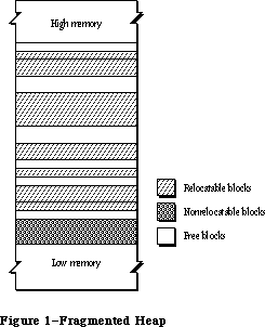 Figure 1–Fragmented Heap
The Memory Manager always maintains at least two heap zones: a system heap zone that’s used by the Operating System and an application heap zone that’s used by the Toolbox and your application program. The system heap zone is initialized to a fixed size when the system starts up.
Note: The initial size of the system heap zone is determined by the system
startup information stored on a volume; for more information, see the
section “Data Organization on Volumes” in the File Manager chapter.
The default initial size of this zone depends on the memory size of the
machine and may be different in future versions of the Macintosh.
Objects in the system heap zone remain allocated even when one application terminates and another starts up. In contrast, the application heap zone is automatically reinitialized at the start of each new application program, and the contents of any previous application zone are lost.
Assembly-language note: If desired, you can prevent the application heap
zone from being reinitialized when an application
starts up; see the discussion of the Chain procedure
in the Segment Loader chapter for details.
The initial size of the application zone is 6K bytes, but it can grow as needed. Your program can create additional heap zones if it chooses, either by subdividing this original application zone or by allocating space on the stack for more heap zones.
Note: In this chapter, unless otherwise stated, the term “application heap
zone” (or “application zone”) always refers to the original application
heap zone provided by the system, before any subdivision.
Your program’s code typically resides in the application zone, in space reserved for it at the request of the Segment Loader. Similarly, the Resource Manager requests space in the application zone to hold resources it has read into memory from a resource file. Toolbox routines that create new entities of various kinds, such as NewWindow, NewControl, and NewMenu, also call the Memory Manager to allocate the space they need.
At any given time, there’s one current heap zone, to which most Memory Manager operations implicitly apply. You can control which heap zone is current by calling a Memory Manager procedure. Whenever the system needs to access its own (system) heap zone, it saves the setting of the current heap zone and restores it later.
Space within a heap zone is divided into contiguous pieces called blocks. The blocks in a zone fill it completely: Every byte in the zone is part of exactly one block, which may be either allocated (reserved for use) or free (available for allocation). Each block has a block header for the Memory Manager’s own use, followed by the block’s contents, the area available for use by your application or the system (see Figure 2). There may also be some unused bytes at the end of the block, beyond the end of the contents. A block can be of any size, limited only by the size of the heap zone itself.
Assembly-language note: Blocks are always aligned on even word boundaries,
so you can access them with word (.W) and long-word
(.L) instructions.
An allocated block may be relocatable or nonrelocatable. Relocatable blocks can be moved around within the heap zone to create space for other blocks; nonrelocatable blocks can never be moved. These are permanent properties of a block. If relocatable, a block may be locked or unlocked; if unlocked, it may be purgeable or unpurgeable. These attributes can be set and changed as necessary. Locking a relocatable block prevents it from being moved. Making a block purgeable allows the Memory Manager to remove it from the heap zone, if necessary, to make room for another block. (Purging of blocks is discussed further below under “How Heap Space Is Allocated”.) A newly allocated relocatable block is initially unlocked and unpurgeable.
Figure 1–Fragmented Heap
The Memory Manager always maintains at least two heap zones: a system heap zone that’s used by the Operating System and an application heap zone that’s used by the Toolbox and your application program. The system heap zone is initialized to a fixed size when the system starts up.
Note: The initial size of the system heap zone is determined by the system
startup information stored on a volume; for more information, see the
section “Data Organization on Volumes” in the File Manager chapter.
The default initial size of this zone depends on the memory size of the
machine and may be different in future versions of the Macintosh.
Objects in the system heap zone remain allocated even when one application terminates and another starts up. In contrast, the application heap zone is automatically reinitialized at the start of each new application program, and the contents of any previous application zone are lost.
Assembly-language note: If desired, you can prevent the application heap
zone from being reinitialized when an application
starts up; see the discussion of the Chain procedure
in the Segment Loader chapter for details.
The initial size of the application zone is 6K bytes, but it can grow as needed. Your program can create additional heap zones if it chooses, either by subdividing this original application zone or by allocating space on the stack for more heap zones.
Note: In this chapter, unless otherwise stated, the term “application heap
zone” (or “application zone”) always refers to the original application
heap zone provided by the system, before any subdivision.
Your program’s code typically resides in the application zone, in space reserved for it at the request of the Segment Loader. Similarly, the Resource Manager requests space in the application zone to hold resources it has read into memory from a resource file. Toolbox routines that create new entities of various kinds, such as NewWindow, NewControl, and NewMenu, also call the Memory Manager to allocate the space they need.
At any given time, there’s one current heap zone, to which most Memory Manager operations implicitly apply. You can control which heap zone is current by calling a Memory Manager procedure. Whenever the system needs to access its own (system) heap zone, it saves the setting of the current heap zone and restores it later.
Space within a heap zone is divided into contiguous pieces called blocks. The blocks in a zone fill it completely: Every byte in the zone is part of exactly one block, which may be either allocated (reserved for use) or free (available for allocation). Each block has a block header for the Memory Manager’s own use, followed by the block’s contents, the area available for use by your application or the system (see Figure 2). There may also be some unused bytes at the end of the block, beyond the end of the contents. A block can be of any size, limited only by the size of the heap zone itself.
Assembly-language note: Blocks are always aligned on even word boundaries,
so you can access them with word (.W) and long-word
(.L) instructions.
An allocated block may be relocatable or nonrelocatable. Relocatable blocks can be moved around within the heap zone to create space for other blocks; nonrelocatable blocks can never be moved. These are permanent properties of a block. If relocatable, a block may be locked or unlocked; if unlocked, it may be purgeable or unpurgeable. These attributes can be set and changed as necessary. Locking a relocatable block prevents it from being moved. Making a block purgeable allows the Memory Manager to remove it from the heap zone, if necessary, to make room for another block. (Purging of blocks is discussed further below under “How Heap Space Is Allocated”.) A newly allocated relocatable block is initially unlocked and unpurgeable.
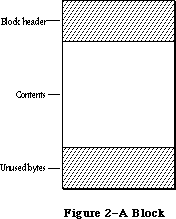 Figure 2–A Block
Relocatable blocks are moved only by the Memory Manager, and only at well-defined, predictable times. In particular, only the routines listed in Appendix B can cause blocks to move, and these routines can never be called from within an interrupt. If your program doesn’t call these routines, you can rely on blocks not being moved.
Many existing Memory Manager routines have been improved; most of these improvements are transparent to the programmer.
SetHandleSize is smarter about finding free space below, as well as above, the relocatable block.
Routines have been provided for the setting and clearing of handle flags.
_______________________________________________________________________________
»POINTERS AND HANDLES
_______________________________________________________________________________
Relocatable and nonrelocatable blocks are referred to in different ways: nonrelocatable blocks by pointers, relocatable blocks by handles. When the Memory Manager allocates a new block, it returns a pointer or handle to the contents of the block (not to the block’s header) depending on whether the block is nonrelocatable (Figure 3) or relocatable (Figure 4).
Figure 2–A Block
Relocatable blocks are moved only by the Memory Manager, and only at well-defined, predictable times. In particular, only the routines listed in Appendix B can cause blocks to move, and these routines can never be called from within an interrupt. If your program doesn’t call these routines, you can rely on blocks not being moved.
Many existing Memory Manager routines have been improved; most of these improvements are transparent to the programmer.
SetHandleSize is smarter about finding free space below, as well as above, the relocatable block.
Routines have been provided for the setting and clearing of handle flags.
_______________________________________________________________________________
»POINTERS AND HANDLES
_______________________________________________________________________________
Relocatable and nonrelocatable blocks are referred to in different ways: nonrelocatable blocks by pointers, relocatable blocks by handles. When the Memory Manager allocates a new block, it returns a pointer or handle to the contents of the block (not to the block’s header) depending on whether the block is nonrelocatable (Figure 3) or relocatable (Figure 4).
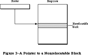 Figure 3–A Pointer to a Nonrelocatable Block
A pointer to a nonrelocatable block never changes, since the block itself can’t move. A pointer to a relocatable block can change, however, since the block can move. For this reason, the Memory Manager maintains a single nonrelocatable master pointer to each relocatable block. The master pointer is created at the same time as the block and set to point to it. When you allocate a relocatable block, the Memory Manager returns a pointer to the master pointer, called a handle to the block (see Figure 4). If the Memory Manager later has to move the block, it has only to update the master pointer to point to the block’s new location.
Figure 3–A Pointer to a Nonrelocatable Block
A pointer to a nonrelocatable block never changes, since the block itself can’t move. A pointer to a relocatable block can change, however, since the block can move. For this reason, the Memory Manager maintains a single nonrelocatable master pointer to each relocatable block. The master pointer is created at the same time as the block and set to point to it. When you allocate a relocatable block, the Memory Manager returns a pointer to the master pointer, called a handle to the block (see Figure 4). If the Memory Manager later has to move the block, it has only to update the master pointer to point to the block’s new location.
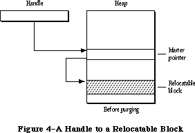 Figure 4–A Handle to a Relocatable Block
_______________________________________________________________________________
»HOW HEAP SPACE IS ALLOCATED
_______________________________________________________________________________
The Memory Manager allocates space for relocatable blocks according to a “first fit” strategy. It looks for a free block of at least the requested size, scanning forward from the end of the last block allocated and “wrapping around” from the top of the zone to the bottom if necessary. As soon as it finds a free block big enough, it allocates the requested number of bytes from that block.
If a single free block can’t be found that’s big enough, the Memory Manager will try to create the needed space by compacting the heap zone: moving allocated blocks together in order to collect the free space into a single larger block. Only relocatable, unlocked blocks are moved. The compaction continues until either a free block of at least the requested size has been created or the entire heap zone has been compacted. Figure 5 illustrates what happens when the entire heap must be compacted to create a large enough free block.
Nonrelocatable blocks (and relocatable ones that are temporarily locked) interfere with the compaction process by forming immovable “islands” in the heap. This can prevent free blocks from being collected together and lead to fragmentation of the available free space, as shown in Figure 6. (Notice that the Memory Manager will never move a relocatable block around a nonrelocatable block.) To minimize this problem, the Memory Manager tries to keep all the nonrelocatable blocks together at the bottom of the heap zone. When you allocate a nonrelocatable block, the Memory Manager will try to make room for the new block near the bottom of the zone, by moving other blocks upward, expanding the zone, or purging blocks from it (see below).
Warning: To avoid heap fragmentation, use relocatable instead of
nonrelocatable blocks.
Figure 4–A Handle to a Relocatable Block
_______________________________________________________________________________
»HOW HEAP SPACE IS ALLOCATED
_______________________________________________________________________________
The Memory Manager allocates space for relocatable blocks according to a “first fit” strategy. It looks for a free block of at least the requested size, scanning forward from the end of the last block allocated and “wrapping around” from the top of the zone to the bottom if necessary. As soon as it finds a free block big enough, it allocates the requested number of bytes from that block.
If a single free block can’t be found that’s big enough, the Memory Manager will try to create the needed space by compacting the heap zone: moving allocated blocks together in order to collect the free space into a single larger block. Only relocatable, unlocked blocks are moved. The compaction continues until either a free block of at least the requested size has been created or the entire heap zone has been compacted. Figure 5 illustrates what happens when the entire heap must be compacted to create a large enough free block.
Nonrelocatable blocks (and relocatable ones that are temporarily locked) interfere with the compaction process by forming immovable “islands” in the heap. This can prevent free blocks from being collected together and lead to fragmentation of the available free space, as shown in Figure 6. (Notice that the Memory Manager will never move a relocatable block around a nonrelocatable block.) To minimize this problem, the Memory Manager tries to keep all the nonrelocatable blocks together at the bottom of the heap zone. When you allocate a nonrelocatable block, the Memory Manager will try to make room for the new block near the bottom of the zone, by moving other blocks upward, expanding the zone, or purging blocks from it (see below).
Warning: To avoid heap fragmentation, use relocatable instead of
nonrelocatable blocks.
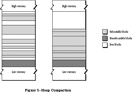 Figure 5–Heap Compaction
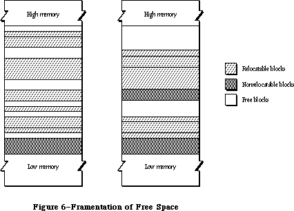 Figure 6–Fragmentation of Free Space
If the Memory Manager can’t satisfy the allocation request after compacting the entire heap zone, it next tries expanding the zone by the requested number of bytes (rounded up to the nearest 1K bytes). Only the original application zone can be expanded, and only up to a certain limit (discussed more fully under
“The Stack and the Heap”). If any other zone is current, or if the application zone has already reached or exceeded its limit, this step is skipped.
Next the Memory Manager tries to free space by purging blocks from the zone. Only relocatable blocks can be purged, and then only if they’re explicitly marked as unlocked and purgeable. Purging a block removes it from its heap zone and frees the space it occupies. The space occupied by the block’s master pointer itself remains allocated, but the master pointer is set to NIL. Any handles to the block now point to a NIL master pointer, and are said to be empty. If your program later needs to refer to the purged block, it must detect that the handle has become empty and ask the Memory Manager to reallocate the block. This operation updates the master pointer (see Figure 7).
Warning: Reallocating a block recovers only its space, not its contents
(which were lost when the block was purged). It’s up to your
program to reconstitute the block’s contents.
Finally, if all else fails, the Memory Manager calls the grow zone function, if any, for the current heap zone. This is an optional routine that an application can provide to take any last-ditch measures to try to “grow” the zone by freeing some space in it. The grow zone function can try to create additional free space by purging blocks that were previously marked unpurgeable, unlocking previously locked blocks, and so on. The Memory Manager will call the grow zone function repeatedly, compacting the heap again after each call, until either it finds the space it’s looking for or the grow zone function has exhausted all possibilities. In the latter case, the Memory Manager will finally give up and report that it’s unable to satisfy the allocation request.
Note: The Memory Manager moves a block by copying the entire block to a new
location; it won’t “slide” a block up or down in memory. If there isn’t
free space at least as large as the block, the block is effectively not
relocatable.
_______________________________________________________________________________
»Dereferencing a Handle
Accessing a block by double indirection, through its handle instead of through its master pointer, requires an extra memory reference. For efficiency, you may sometimes want to dereference the handle—that is, make a copy of the block’s master pointer, and then use that pointer to access the block by single indirection. But be careful! Any operation that allocates space from the heap may cause the underlying block to be moved or purged. In that event, the master pointer itself will be correctly updated, but your copy of it will be left dangling.
One way to avoid this common type of program bug is to lock the block before dereferencing its handle. For example:
VAR aPointer: Ptr;
aHandle: Handle;
. . .
aHandle := NewHandle(...); {create relocatable block}
. . .
HLock(aHandle); {lock before dereferencing}
aPointer := aHandle^; {dereference handle}
WHILE ... DO
BEGIN
...aPointer^... {use simple pointer}
END;
HUnlock(aHandle) {unlock block when finished}
Figure 6–Fragmentation of Free Space
If the Memory Manager can’t satisfy the allocation request after compacting the entire heap zone, it next tries expanding the zone by the requested number of bytes (rounded up to the nearest 1K bytes). Only the original application zone can be expanded, and only up to a certain limit (discussed more fully under
“The Stack and the Heap”). If any other zone is current, or if the application zone has already reached or exceeded its limit, this step is skipped.
Next the Memory Manager tries to free space by purging blocks from the zone. Only relocatable blocks can be purged, and then only if they’re explicitly marked as unlocked and purgeable. Purging a block removes it from its heap zone and frees the space it occupies. The space occupied by the block’s master pointer itself remains allocated, but the master pointer is set to NIL. Any handles to the block now point to a NIL master pointer, and are said to be empty. If your program later needs to refer to the purged block, it must detect that the handle has become empty and ask the Memory Manager to reallocate the block. This operation updates the master pointer (see Figure 7).
Warning: Reallocating a block recovers only its space, not its contents
(which were lost when the block was purged). It’s up to your
program to reconstitute the block’s contents.
Finally, if all else fails, the Memory Manager calls the grow zone function, if any, for the current heap zone. This is an optional routine that an application can provide to take any last-ditch measures to try to “grow” the zone by freeing some space in it. The grow zone function can try to create additional free space by purging blocks that were previously marked unpurgeable, unlocking previously locked blocks, and so on. The Memory Manager will call the grow zone function repeatedly, compacting the heap again after each call, until either it finds the space it’s looking for or the grow zone function has exhausted all possibilities. In the latter case, the Memory Manager will finally give up and report that it’s unable to satisfy the allocation request.
Note: The Memory Manager moves a block by copying the entire block to a new
location; it won’t “slide” a block up or down in memory. If there isn’t
free space at least as large as the block, the block is effectively not
relocatable.
_______________________________________________________________________________
»Dereferencing a Handle
Accessing a block by double indirection, through its handle instead of through its master pointer, requires an extra memory reference. For efficiency, you may sometimes want to dereference the handle—that is, make a copy of the block’s master pointer, and then use that pointer to access the block by single indirection. But be careful! Any operation that allocates space from the heap may cause the underlying block to be moved or purged. In that event, the master pointer itself will be correctly updated, but your copy of it will be left dangling.
One way to avoid this common type of program bug is to lock the block before dereferencing its handle. For example:
VAR aPointer: Ptr;
aHandle: Handle;
. . .
aHandle := NewHandle(...); {create relocatable block}
. . .
HLock(aHandle); {lock before dereferencing}
aPointer := aHandle^; {dereference handle}
WHILE ... DO
BEGIN
...aPointer^... {use simple pointer}
END;
HUnlock(aHandle) {unlock block when finished}
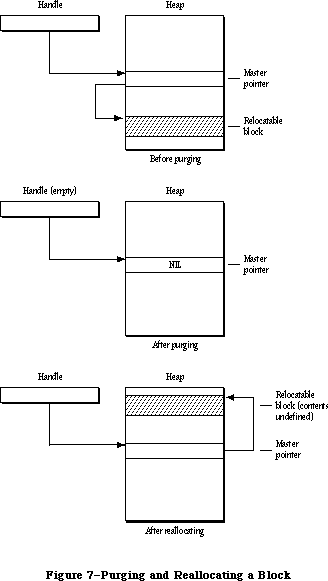 Figure 7–Purging and Reallocating a Block
Assembly-language note: To dereference a handle in assembly language, just
copy the master pointer into an address register
and use it to access the block by single indirection.
Remember, however, that when you lock a block it becomes an “island” in the heap that may interfere with compaction and cause free space to become fragmented. It’s recommended that you use this technique only in parts of your program where efficiency is critical, such as inside tight inner loops that are executed many times (and that don’t allocate other blocks).
Warning: Don’t forget to unlock the block again when you’re through with
the dereferenced handle.
Instead of locking the block, you can update your copy of the master pointer after any “dangerous” operation (one that can invalidate the pointer by moving or purging the block it points to). For a complete list of all routines that may move or purge blocks, see Appendix B.
The Lisa Pascal compiler frequently dereferences handles during its normal operation. You should take care to write code that will protect you when the compiler dereferences handles in the following cases:
• Use of the WITH statement with a handle, such as
WITH aHandle^^ DO ...
• Assigning the result of a function that can move or purge blocks (or
of any function in a package or another segment) to a field in a record
referred to by a handle, such as
aHandle^^.field := NewHandle(...)
A problem may arise because the compiler generates code that dereferences
the handle before calling NewHandle—and NewHandle may move the block
containing the field.
• Passing an argument of more than four bytes referred to by a handle, to
a routine that can move or purge a block or to any routine in a package
or another segment. For example:
TEUpdate(hTE^^.viewRect,hTE)
or
DrawString(theControl^^.contrlTitle)
You can avoid having the compiler generate and use dangling pointers by locking a block before you use its handle in the above situations. Or you can use temporary variables, as in the following:
temp := NewHandle(...);
aHandle^^.field := temp
_______________________________________________________________________________
»THE STACK AND THE HEAP
_______________________________________________________________________________
The LIFO nature of the stack makes it particularly convenient for memory allocation connected with the activation and deactivation of routines
(procedures and functions). Each time a routine is called, space is allocated for a stack frame. The stack frame holds the routine’s parameters, local variables, and return address. Upon exit from the routine, the stack frame is released, restoring the stack to the same state it was in when the routine was called.
In Lisa Pascal, all stack management is done by the compiler. When you call a routine, the compiler generates code to reserve space if necessary for a function result, place the parameter values and return link on the stack, and jump to the routine. The routine can then allocate space on the stack for its own local variables.
Before returning, the routine releases the stack space occupied by its local variables, return link, and parameters. If the routine is a function, it leaves its result on the stack for the calling program.
The application heap zone and the stack share the same area in memory, growing toward each other from opposite ends (see Figure 8). Naturally it would be disastrous for either to grow so far that it collides with the other. To help prevent such collisions, the Memory Manager enforces a limit on how far the application heap zone can grow toward the stack. Your program can set this application heap limit to control the allotment of available space between the stack and the heap.
Figure 7–Purging and Reallocating a Block
Assembly-language note: To dereference a handle in assembly language, just
copy the master pointer into an address register
and use it to access the block by single indirection.
Remember, however, that when you lock a block it becomes an “island” in the heap that may interfere with compaction and cause free space to become fragmented. It’s recommended that you use this technique only in parts of your program where efficiency is critical, such as inside tight inner loops that are executed many times (and that don’t allocate other blocks).
Warning: Don’t forget to unlock the block again when you’re through with
the dereferenced handle.
Instead of locking the block, you can update your copy of the master pointer after any “dangerous” operation (one that can invalidate the pointer by moving or purging the block it points to). For a complete list of all routines that may move or purge blocks, see Appendix B.
The Lisa Pascal compiler frequently dereferences handles during its normal operation. You should take care to write code that will protect you when the compiler dereferences handles in the following cases:
• Use of the WITH statement with a handle, such as
WITH aHandle^^ DO ...
• Assigning the result of a function that can move or purge blocks (or
of any function in a package or another segment) to a field in a record
referred to by a handle, such as
aHandle^^.field := NewHandle(...)
A problem may arise because the compiler generates code that dereferences
the handle before calling NewHandle—and NewHandle may move the block
containing the field.
• Passing an argument of more than four bytes referred to by a handle, to
a routine that can move or purge a block or to any routine in a package
or another segment. For example:
TEUpdate(hTE^^.viewRect,hTE)
or
DrawString(theControl^^.contrlTitle)
You can avoid having the compiler generate and use dangling pointers by locking a block before you use its handle in the above situations. Or you can use temporary variables, as in the following:
temp := NewHandle(...);
aHandle^^.field := temp
_______________________________________________________________________________
»THE STACK AND THE HEAP
_______________________________________________________________________________
The LIFO nature of the stack makes it particularly convenient for memory allocation connected with the activation and deactivation of routines
(procedures and functions). Each time a routine is called, space is allocated for a stack frame. The stack frame holds the routine’s parameters, local variables, and return address. Upon exit from the routine, the stack frame is released, restoring the stack to the same state it was in when the routine was called.
In Lisa Pascal, all stack management is done by the compiler. When you call a routine, the compiler generates code to reserve space if necessary for a function result, place the parameter values and return link on the stack, and jump to the routine. The routine can then allocate space on the stack for its own local variables.
Before returning, the routine releases the stack space occupied by its local variables, return link, and parameters. If the routine is a function, it leaves its result on the stack for the calling program.
The application heap zone and the stack share the same area in memory, growing toward each other from opposite ends (see Figure 8). Naturally it would be disastrous for either to grow so far that it collides with the other. To help prevent such collisions, the Memory Manager enforces a limit on how far the application heap zone can grow toward the stack. Your program can set this application heap limit to control the allotment of available space between the stack and the heap.
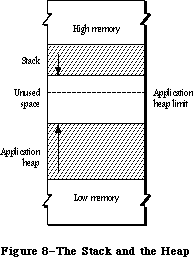 Figure 8–The Stack and the Heap
The application heap limit marks the boundary between the space available for the application heap zone and the space reserved exclusively for the stack. At the start of each application program, the limit is initialized to allow 8K bytes for the stack. Depending on your program’s needs, you can adjust the limit to allow more heap space at the expense of the stack or vice versa.
Assembly-language note: The global variables DefltStack and MinStack
contain the default and minimum sizes of the
stack, respectively.
Notice that the limit applies only to expansion of the heap; it has no effect on how far the stack can expand. Although the heap can never expand beyond the limit into space reserved for the stack, there’s nothing to prevent the stack from crossing the limit. It’s up to you to set the limit low enough to allow for the maximum stack depth your program will ever need.
Note: Regardless of the limit setting, the application zone is never
allowed to grow to within 1K of the current end of the stack. This
gives a little extra protection in case the stack is approaching the
boundary or has crossed over onto the heap’s side, and allows some
safety margin for the stack to expand even further.
To help detect collisions between the stack and the heap, a “stack sniffer” routine is run sixty times a second, during the Macintosh’s vertical retrace interrupt. This routine compares the current ends of the stack and the heap and invokes the System Error Handler in case of a collision.
The stack sniffer can’t prevent collisions, it can only detect them after the fact: A lot of computation can take place in a sixtieth of a second. In fact, the stack can easily expand into the heap, overwrite it, and then shrink back again before the next activation of the stack sniffer, escaping detection completely. The stack sniffer is useful mainly during software development; the alert box the System Error Handler displays can be confusing to your program’s end user. Its purpose is to warn you, the programmer, that your program’s stack and heap are colliding, so that you can adjust the heap limit to correct the problem before the user ever encounters it.
_______________________________________________________________________________
»GENERAL-PURPOSE DATA TYPES
_______________________________________________________________________________
The Memory Manager includes a number of type definitions for general-purpose use. The types listed below are explained in the Macintosh Memory Management: An Introduction chapter.
TYPE SignedByte = -128..127;
Byte = 0..255;
Ptr = ^SignedByte;
Handle = ^Ptr;
Str255 = STRING[255];
StringPtr = ^Str255;
StringHandle = ^StringPtr;
ProcPtr = Ptr;
Fixed = LONGINT;
For specifying the sizes of blocks in the heap, the Memory Manager defines a special type called Size:
TYPE Size = LONGINT;
All Memory Manager routines that deal with block sizes expect parameters of type Size or return them as results.
_______________________________________________________________________________
»MEMORY ORGANIZATION
_______________________________________________________________________________
This section discusses the organization of memory in the Macintosh 128K, 512K, and XL.
Note: The information presented in this section may be different in future
versions of Macintosh system software.
The organization of the Macintosh 128K and 512K RAM is shown in Figure 9. The variable names listed on the right in the figure refer to global variables for use by assembly-language programmers.
Figure 8–The Stack and the Heap
The application heap limit marks the boundary between the space available for the application heap zone and the space reserved exclusively for the stack. At the start of each application program, the limit is initialized to allow 8K bytes for the stack. Depending on your program’s needs, you can adjust the limit to allow more heap space at the expense of the stack or vice versa.
Assembly-language note: The global variables DefltStack and MinStack
contain the default and minimum sizes of the
stack, respectively.
Notice that the limit applies only to expansion of the heap; it has no effect on how far the stack can expand. Although the heap can never expand beyond the limit into space reserved for the stack, there’s nothing to prevent the stack from crossing the limit. It’s up to you to set the limit low enough to allow for the maximum stack depth your program will ever need.
Note: Regardless of the limit setting, the application zone is never
allowed to grow to within 1K of the current end of the stack. This
gives a little extra protection in case the stack is approaching the
boundary or has crossed over onto the heap’s side, and allows some
safety margin for the stack to expand even further.
To help detect collisions between the stack and the heap, a “stack sniffer” routine is run sixty times a second, during the Macintosh’s vertical retrace interrupt. This routine compares the current ends of the stack and the heap and invokes the System Error Handler in case of a collision.
The stack sniffer can’t prevent collisions, it can only detect them after the fact: A lot of computation can take place in a sixtieth of a second. In fact, the stack can easily expand into the heap, overwrite it, and then shrink back again before the next activation of the stack sniffer, escaping detection completely. The stack sniffer is useful mainly during software development; the alert box the System Error Handler displays can be confusing to your program’s end user. Its purpose is to warn you, the programmer, that your program’s stack and heap are colliding, so that you can adjust the heap limit to correct the problem before the user ever encounters it.
_______________________________________________________________________________
»GENERAL-PURPOSE DATA TYPES
_______________________________________________________________________________
The Memory Manager includes a number of type definitions for general-purpose use. The types listed below are explained in the Macintosh Memory Management: An Introduction chapter.
TYPE SignedByte = -128..127;
Byte = 0..255;
Ptr = ^SignedByte;
Handle = ^Ptr;
Str255 = STRING[255];
StringPtr = ^Str255;
StringHandle = ^StringPtr;
ProcPtr = Ptr;
Fixed = LONGINT;
For specifying the sizes of blocks in the heap, the Memory Manager defines a special type called Size:
TYPE Size = LONGINT;
All Memory Manager routines that deal with block sizes expect parameters of type Size or return them as results.
_______________________________________________________________________________
»MEMORY ORGANIZATION
_______________________________________________________________________________
This section discusses the organization of memory in the Macintosh 128K, 512K, and XL.
Note: The information presented in this section may be different in future
versions of Macintosh system software.
The organization of the Macintosh 128K and 512K RAM is shown in Figure 9. The variable names listed on the right in the figure refer to global variables for use by assembly-language programmers.
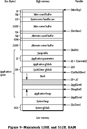 Figure 9–Macintosh 128K and 512K RAM
Assembly-language note: The global variables, shown in parentheses, contain
the addresses of the indicated areas. Names identified
as marking the end of an area actually refer to the
address following the last byte in that area.
The lowest 2816 bytes are used for system globals. Immediately following this are the system heap and the application space, which is memory available for dynamic allocation by applications. Most of the application space is shared between the stack and the application heap, with the heap growing forward from the bottom of the space and the stack growing backward from the top. The remainder of the application space is occupied by QuickDraw global variables, the application’s global variables, the application parameters, and the jump table. The application parameters are 32 bytes of memory located above the application globals; they’re reserved for use by the system. The first application parameter is the address of the first QuickDraw global variable
(thePort). The jump table is explained in the Segment Loader chapter.
Note: Some development systems may place the QuickDraw global variables in
a different location, but the first application parameter will always
point to them.
Assembly-language note: The location pointed to by register A5 will always
point to the first QuickDraw global variable.
At (almost) the very end of memory are the main sound buffer, used by the Sound Driver to control the sounds emitted by the built-in speaker and by the Disk Driver to control disk motor speed, and the main screen buffer, which holds the bit image to be displayed on the Macintosh screen. The area between the main screen and sound buffers is used by the System Error Handler.
There are alternate screen and sound buffers for special applications. If you use either or both of these, the memory available for use by your application is reduced accordingly. The Segment Loader provides routines for specifying that an alternate screen or sound buffer will be used.
Note: The alternate screen and sound buffers are only supported on the
Macintosh 128K, 512K (including enhanced), Plus, and SE.
The memory organization of a Macintosh XL is shown in Figure 10.
Figure 9–Macintosh 128K and 512K RAM
Assembly-language note: The global variables, shown in parentheses, contain
the addresses of the indicated areas. Names identified
as marking the end of an area actually refer to the
address following the last byte in that area.
The lowest 2816 bytes are used for system globals. Immediately following this are the system heap and the application space, which is memory available for dynamic allocation by applications. Most of the application space is shared between the stack and the application heap, with the heap growing forward from the bottom of the space and the stack growing backward from the top. The remainder of the application space is occupied by QuickDraw global variables, the application’s global variables, the application parameters, and the jump table. The application parameters are 32 bytes of memory located above the application globals; they’re reserved for use by the system. The first application parameter is the address of the first QuickDraw global variable
(thePort). The jump table is explained in the Segment Loader chapter.
Note: Some development systems may place the QuickDraw global variables in
a different location, but the first application parameter will always
point to them.
Assembly-language note: The location pointed to by register A5 will always
point to the first QuickDraw global variable.
At (almost) the very end of memory are the main sound buffer, used by the Sound Driver to control the sounds emitted by the built-in speaker and by the Disk Driver to control disk motor speed, and the main screen buffer, which holds the bit image to be displayed on the Macintosh screen. The area between the main screen and sound buffers is used by the System Error Handler.
There are alternate screen and sound buffers for special applications. If you use either or both of these, the memory available for use by your application is reduced accordingly. The Segment Loader provides routines for specifying that an alternate screen or sound buffer will be used.
Note: The alternate screen and sound buffers are only supported on the
Macintosh 128K, 512K (including enhanced), Plus, and SE.
The memory organization of a Macintosh XL is shown in Figure 10.
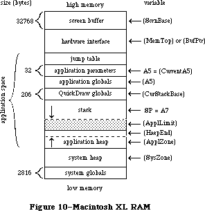 Figure 10–Macintosh XL RAM
_______________________________________________________________________________
»MEMORY MANAGER DATA STRUCTURES
_______________________________________________________________________________
This section discusses the internal data structures of the Memory Manager. You don’t need to know this information if you’re just using the Memory Manager routinely to allocate and release blocks of memory from the application heap zone.
Figure 10–Macintosh XL RAM
_______________________________________________________________________________
»MEMORY MANAGER DATA STRUCTURES
_______________________________________________________________________________
This section discusses the internal data structures of the Memory Manager. You don’t need to know this information if you’re just using the Memory Manager routinely to allocate and release blocks of memory from the application heap zone.
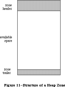 Figure 11–Structure of a Heap Zone
_______________________________________________________________________________
»Structure of Heap Zones
Each heap zone begins with a 52-byte zone header and ends with a 12-byte zone trailer (see Figure 11). The header contains all the information the Memory Manager needs about that heap zone; the trailer is just a minimum-size free block (described in the next section) placed at the end of the zone as a marker. All the remaining space between the header and trailer is available for allocation.
In Pascal, a heap zone is defined as a zone record of type Zone. It’s always referred to with a zone pointer of type THz (“the heap zone”):
TYPE THz = ^Zone;
Zone = RECORD
bkLim: Ptr; {zone trailer block}
purgePtr: Ptr; {used internally}
hFstFree: Ptr; {first free master pointer}
zcbFree: LONGINT; {number of free bytes}
gzProc: ProcPtr; {grow zone function}
moreMast: INTEGER; {master pointers to allocate}
flags: INTEGER; {used internally}
cntRel: INTEGER; {not used}
maxRel: INTEGER; {not used}
cntNRel: INTEGER; {not used}
maxNRel: INTEGER; {not used}
cntEmpty: INTEGER; {not used}
cntHandles: INTEGER; {not used}
minCBFree: LONGINT; {not used}
purgeProc: ProcPtr; {purge warning procedure}
sparePtr: Ptr; {used internally}
allocPtr: Ptr; {used internally}
heapData: INTEGER {first usable byte in zone}
END;
Warning: The fields of the zone header are for the Memory Manager’s own
internal use. You can examine the contents of the zone’s fields,
but in general it doesn’t make sense for your program to try to
change them. The few exceptions are noted below in the discussions
of the specific fields.
BkLim is a pointer to the zone’s trailer block. Since the trailer is the last block in the zone, bkLim is a pointer to the byte following the last byte of usable space in the zone.
HFstFree is a pointer to the first free master pointer in the zone. Instead of just allocating space for one master pointer each time a relocatable block is created, the Memory Manager “preallocates” several master pointers at a time; as a group they form a nonrelocatable block. The moreMast field of the zone record tells the Memory Manager how many master pointers at a time to preallocate for this zone.
Note: Master pointers are allocated 32 at a time for the system heap zone
and 64 at a time for the application zone; this may be different on
future versions of the Macintosh.
All master pointers that are allocated but not currently in use are linked together into a list beginning in the hFstFree field. When you allocate a new relocatable block, the Memory Manager removes the first available master pointer from this list, sets it to point to the new block, and returns its address to you as a handle to the block. (If the list is empty, it allocates a fresh block of moreMast master pointers.) When you release a relocatable block, its master pointer isn’t released, but is linked onto the beginning of the list to be reused. Thus the amount of space devoted to master pointers can increase, but can never decrease until the zone is reinitialized.
The zcbFree field always contains the number of free bytes remaining in the zone. As blocks are allocated and released, the Memory Manager adjusts zcbFree accordingly. This number represents an upper limit on the size of block you can allocate from this heap zone.
Warning: It may not actually be possible to allocate a block as big as
zcbFree bytes. Because nonrelocatable and locked blocks can’t be
moved, it isn’t always possible to collect all the free space into
a single block by compaction.
The gzProc field is a pointer to the grow zone function. You can supply a pointer to your own grow zone function when you create a new heap zone and can change it at any time.
Warning: Don’t store directly into the gzProc field; if you want to supply
your own grow zone function, you must do so with a procedure call
(InitZone or SetGrowZone).
PurgeProc is a pointer to the zone’s purge warning procedure, or NIL if there is none. The Memory Manager will call this procedure before it purges a block from the zone.
Warning: Whenever you call the Resource Manager with SetResPurge(TRUE),
it installs its own purge warning procedure, overriding any purge
warning procedure you’ve specified to the Memory Manager; for further
details, see the Resource Manager chapter.
The last field of a zone record, heapData, is a dummy field marking the bottom of the zone’s usable memory space.
HeapData nominally contains an integer, but this integer has no significance in itself—it’s just the first two bytes in the block header of the first block in the zone. The purpose of the heapData field is to give you a way of locating the effective bottom of the zone. For example, if myZone is a zone pointer, then
@(myZone^.heapData)
is a pointer to the first usable byte in the zone, just as
myZone^.bkLim
is a pointer to the byte following the last usable byte in the zone.
_______________________________________________________________________________
»Structure of Blocks
Every block in a heap zone, whether allocated or free, has a block header that the Memory Manager uses to find its way around in the zone. Block headers are completely transparent to your program. All pointers and handles to allocated blocks point to the beginning of the block’s contents, following the end of the header. Similarly, all block sizes seen by your program refer to the block’s logical size (the number of bytes in its contents) rather than its physical size (the number of bytes it actually occupies in memory, including the header and any unused bytes at the end of the block).
Since your program shouldn’t normally have to deal with block headers directly, there’s no Pascal record type defining their structure. A block header consists of eight bytes, as shown in Figure 12.
(archivist's note: Figure 12 is missing from SpInside Macintosh 2.0.2)
Figure 12–Block Header
The first byte of the block header is the tag byte, discussed below. The next three bytes contain the block’s physical size in bytes. Adding this number to the block’s address gives the address of the next block in the zone.
The contents of the second long word (four bytes) in the block header depend on the type of block. For relocatable blocks, it contains the block’s relative handle: a pointer to the block’s master pointer, expressed as an offset relative to the start of the heap zone rather than as an absolute memory address. Adding the relative handle to the zone pointer produces a true handle for this block. For nonrelocatable blocks, the second long word of the header is just a pointer to the block’s zone. For free blocks, these four bytes are unused.
The structure of a tag byte is shown in Figure 13.
(archivist's note: Figure 13 is missing from SpInside Macintosh 2.0.2)
Figure 13–Tag Byte
Assembly-language note: You can use the global constants tyBkFree, tyBkNRel,
and tyBkRel to test whether the value of the tag
byte indicates a free, nonrelocatable, or relocatable
block, respectively.
The “size correction” in the tag byte of a block header is the number of unused bytes at the end of the block, beyond the end of the block’s contents. It’s equal to the difference between the block’s logical and physical sizes, excluding the eight bytes of overhead for the block header:
physicalSize = logicalSize + sizeCorrection + 8
There are two reasons why a block may contain such unused bytes:
• The Memory Manager allocates space only in even numbers of bytes. If
the block’s logical size is odd, an extra, unused byte is added at the
end to keep the physical size even.
• The minimum number of bytes in a block is 12. This minimum applies to
all blocks, free as well as allocated. If allocating the required number
of bytes from a free block would leave a fragment of fewer than 12 free
bytes, the leftover bytes are included unused at the end of the newly
allocated block instead of being returned to free storage.
_______________________________________________________________________________
»Structure of Master Pointers
The master pointer to a relocatable block has the structure shown in Figure 14. The low-order three bytes of the long word contain the address of the block’s contents. The high-order byte contains some flag bits that specify the block’s current status. Bit 7 of this byte is the lock bit (1 if the block is locked, 0 if it’s unlocked); bit 6 is the purge bit (1 if the block is purgeable, 0 if
it’s unpurgeable). Bit 5 is used by the Resource Manager to identify blocks containing resource information; such blocks are marked by a 1 in this bit.
(archivist's note: Figure 14 is missing from SpInside Macintosh 2.0.2)
Figure 14–Structure of a Master Pointer
Warning: Note that the flag bits in the high-order byte have numerical
significance in any operation performed on a master pointer. For
example, the lock bit is also the sign bit.
Assembly-language note: You can use the mask in the global variable
Lo3Bytes to determine the value of the low-order
three bytes of a master pointer. To determine the
value of bits 5, 6, and 7, you can use the global
constants resourc, purge, and lock, respectively.
_______________________________________________________________________________
»USING THE MEMORY MANAGER
_______________________________________________________________________________
There’s ordinarily no need to initialize the Memory Manager before using it. The system heap zone is automatically initialized each time the system starts up, and the application heap zone each time an application program starts up. In the unlikely event that you need to reinitialize the application zone while your program is running, you can call InitApplZone.
When your application starts up, it should allocate the memory it requires in the most space-efficient manner possible, ensuring that most of the nonrelocatable blocks it will need are packed together at the bottom of the heap. The main segment of your program should call the MaxApplZone procedure, which expands the application heap zone to its limit. Then call the procedure MoreMasters repeatedly to allocate as many blocks of master pointers as your application and any desk accessories will need. Next initialize QuickDraw and the Window Manager (if you’re going to use it).
To allocate a new relocatable block, use NewHandle; for a nonrelocatable block, use NewPtr. These functions return a handle or a pointer, as the case may be, to the newly allocated block. To release a block when you’re finished with it, use DisposHandle or DisposPtr.
You can also change the size of an already allocated block with SetHandleSize or SetPtrSize, and find out its current size with GetHandleSize or GetPtrSize. Use HLock and HUnlock to lock and unlock relocatable blocks. Before locking a relocatable block, call MoveHHi.
Note: If you lock a relocatable block, unlock it at the earliest possible
opportunity. Before allocating a block that you know will be locked
for long periods of time, call ResrvMem to make room for the block
as near as possible to the bottom of the zone.
In some situations it may be desirable to determine the handle that points to a given master pointer. To do this you can call the RecoverHandle function. For example, a relocatable block of code might want to find out the handle that refers to it, so it can lock itself down in the heap.
Ordinarily, you shouldn’t have to worry about compacting the heap or purging blocks from it; the Memory Manager automatically takes care of this for you. You can control which blocks are purgeable with HPurge and HNoPurge. If for some reason you want to compact or purge the heap explicitly, you can do so with CompactMem or PurgeMem. To explicitly purge a specific block, use EmptyHandle.
Warning: Before attempting to access any purgeable block, you must check
its handle to make sure the block is still allocated. If the handle
is empty, then the block has been purged; before accessing it, you
have to reallocate it by calling ReallocHandle, and then recreate
its contents. (If it’s a resource block, just call the Resource
Manager procedure LoadResource; it checks the handle and reads the
resource into memory if it’s not already in memory.)
You can find out how much free space is left in a heap zone by calling FreeMem
(to get the total number of free bytes) or MaxMem (to get the size of the largest single free block and the maximum amount by which the zone can grow). Beware: MaxMem compacts the entire zone and purges all purgeable blocks. To determine the current application heap limit, use GetApplLimit; to limit the growth of the application zone, use SetApplLimit. To install a grow zone function to help the Memory Manager allocate space in a zone, use SetGrowZone.
You can create additional heap zones for your program’s own use, either within the original application zone or in the stack, with InitZone. If you do maintain more than one heap zone, you can find out which zone is current at any given time with GetZone and switch from one to another with SetZone. Almost all Memory Manager operations implicitly apply to the current heap zone. To refer to the system heap zone or the (original) application heap zone, use the Memory Manager function SystemZone or ApplicZone. To find out which zone a particular block resides in, use HandleZone (if the block is relocatable) or PtrZone (if it’s nonrelocatable).
Warning: Be sure, when calling routines that access blocks, that the zone
in which the block is located is the current zone.
Note: Most applications will just use the original application heap zone
and never have to worry about which zone is current.
After calling any Memory Manager routine, you can determine whether it was successfully completed or failed, by calling MemError.
Warning: Code that will be executed via an interrupt must not make any
calls to the Memory Manager, directly or indirectly, and can’t
depend on handles to unlocked blocks being valid.
_______________________________________________________________________________
»MEMORY MANAGER ROUTINES
_______________________________________________________________________________
In addition to their normal results, many Memory Manager routines yield a result code that you can examine by calling the MemError function. The description of each routine includes a list of all result codes it may yield.
Assembly-language note: When called from assembly language, not all Memory
Manager routines return a result code. Those that do
always leave it as a word-length quantity in the
low-order word of register D0 on return from the trap.
However, some routines leave something else there
instead; see the descriptions of individual routines
for details. Just before returning, the trap
dispatcher tests the low-order word of D0 with a
TST.W instruction, so that on return from the trap
the condition codes reflect the status of the result
code, if any.
The stack-based interface routines called from Pascal
always yield a result code. If the underlying trap
doesn’t return one, the interface routine
“manufactures” a result code of noErr and stores it
where it can later be accessed with MemError.
Assembly-language note: You can specify that some Memory Manager routines
apply to the system heap zone instead of the current
zone by setting bit 10 of the routine trap word. If
you’re using the Lisa Workshop Assembler, you do this
by supplying the word SYS (uppercase) as the second
argument to the routine macro:
_FreeMem ,SYS
If you want a block of memory to be cleared to zeroes
when it’s allocated by a NewPtr or NewHandle call, set
bit 9 of the routine trap word. You can do this by
supplying the word CLEAR (uppercase) as the second
argument to the routine macro:
_NewHandle ,CLEAR
You can combine SYS and CLEAR in the same macro call,
but SYS must come first:
_NewHandle ,SYS,CLEAR
The description of each routine lists whether SYS or
CLEAR is applicable. (The syntax shown above and in
the routine descriptions applies to the Lisa Workshop
Assembler; programmers using another development
system should consult its documentation for the
proper syntax.)
Two Memory Manager routines—MaxApplZone and MoveHHi—that were not in the 64K ROM have been added to the 128K ROM.
_______________________________________________________________________________
»Initialization and Allocation
PROCEDURE InitApplZone;
Trap macro _InitApplZone
On exit D0: result code (word)
InitApplZone initializes the application heap zone and makes it the current zone. The contents of any previous application zone are lost; all previously existing blocks in that zone are discarded. The zone’s grow zone function is set to NIL. InitApplZone is called by the Segment Loader when starting up an application; you shouldn’t normally need to call it.
Warning: Reinitializing the application zone from within a running program
is tricky, since the program’s code itself normally resides in the
application zone. To do it safely, the code containing the
InitApplZone call cannot be in the application zone.
Result codes noErr No error
PROCEDURE SetApplBase (startPtr: Ptr);
Trap macro _SetAppBase
On entry A0: startPtr (pointer)
On exit D0: result code (word)
SetApplBase changes the starting address of the application heap zone to the address designated by startPtr, and then calls InitApplZone. SetApplBase is normally called only by the system itself; you should never need to call this procedure.
Since the application heap zone begins immediately following the end of the system zone, changing its starting address has the effect of changing the size of the system zone. The system zone can be made larger, but never smaller; if startPtr points to an address lower than the current end of the system zone,
it’s ignored and the application zone’s starting address is left unchanged.
Warning: Like InitApplZone, SetApplBase is a tricky operation, because the
program’s code itself normally resides in the application heap zone.
To do it safely, the code containing the SetApplBase call cannot be
in the application zone.
Result codes noErr No error
PROCEDURE InitZone (pGrowZone: ProcPtr; cMoreMasters: INTEGER;
limitPtr,startPtr: Ptr);
Trap macro _InitZone
On entry A0: pointer to parameter block
Parameter block
0 startPtr pointer
4 limitPtr pointer
8 cMoreMasters word
10 pGrowZone pointer
On exit D0: result code (word)
InitZone creates a new heap zone, initializes its header and trailer, and makes it the current zone. The startPtr parameter is a pointer to the first byte of the new zone; limitPtr points to the first byte beyond the end of the zone. The new zone will occupy memory addresses from ORD(startPtr) through
ORD(limitPtr)–1.
CMoreMasters tells how many master pointers should be allocated at a time for the new zone. This number of master pointers are created initially; should more be needed later, they’ll be added in increments of this same number.
The pGrowZone parameter is a pointer to the grow zone function for the new zone, if any. If you’re not defining a grow zone function for this zone, pass NIL.
The new zone includes a 52-byte header and a 12-byte trailer, so its actual usable space runs from ORD(startPtr)+52 through ORD(limitPtr)–13. In addition, there’s an eight-byte header for the master pointer block, as well as four bytes for each master pointer, within this usable area. Thus the total available space in the zone, in bytes, is initially
ORD(limitPtr) – ORD(startPtr) – 64 – (8 + (4*cMoreMasters))
This number must not be less than 0. Note that the amount of available space in the zone will decrease as more master pointers are allocated.
Result codes noErr No error
FUNCTION GetApplLimit : Ptr; [Not in ROM]
GetApplLimit returns the current application heap limit. It can be used in conjunction with SetApplLimit, described below, to determine and then change the application heap limit.
Assembly-language note: The global variable ApplLimit contains the
current application heap limit.
PROCEDURE SetApplLimit (zoneLimit: Ptr);
Trap macro _SetApplLimit
On entry A0: zoneLimit (pointer)
On exit D0: result code (word)
SetApplLimit sets the application heap limit, beyond which the application heap can’t be expanded. The actual expansion isn’t under your program’s control, but is done automatically by the Memory Manager when necessary to satisfy allocation requests. Only the original application zone can be expanded.
ZoneLimit is a pointer to a byte in memory beyond which the zone will not be allowed to grow. The zone can grow to include the byte preceding zoneLimit in memory, but no farther. If the zone already extends beyond the specified limit it won’t be cut back, but it will be prevented from growing any more.
Warning: Notice that zoneLimit is not a byte count. To limit the application
zone to a particular size (say 8K bytes), you have to write something
like
SetApplLimit(Ptr(ApplicZone)+8192)
The Memory Manager function ApplicZone is explained below.
Assembly-language note: You can just store the new application heap
limit in the global variable ApplLimit.
Result codes noErr No error
memFullErr Not enough room in heap zone
PROCEDURE MaxApplZone; [Not in 64K ROM]
Trap macro _MaxApplZone
On exit D0: result code (word)
MaxApplZone expands the application heap zone to the application heap limit without purging any blocks currently in the zone. If the zone already extends to the limit, it won’t be changed.
Assembly-language note: To expand the application heap zone to the
application heap limit from assembly language,
call this Pascal procedure from your program.
Result codes noErr No error
PROCEDURE MoreMasters;
Trap macro _MoreMasters
MoreMasters allocates another block of master pointers in the current heap zone. This procedure is usually called very early in an application.
Result codes noErr No error
memFullErr Not enough room in heap zone
_______________________________________________________________________________
»Heap Zone Access
FUNCTION GetZone : THz;
Trap macro _GetZone
On exit A0: function result (pointer)
D0: result code (word)
GetZone returns a pointer to the current heap zone.
Assembly-language note: The global variable TheZone contains a
pointer to the current heap zone.
Result codes noErr No error
PROCEDURE SetZone (hz: THz);
Trap macro _SetZone
On entry A0: hz (pointer)
On exit D0: result code (word)
SetZone sets the current heap zone to the zone pointed to by hz.
Assembly-language note: You can set the current heap zone by storing
a pointer to it in the global variable TheZone.
Result codes noErr No error
FUNCTION SystemZone : THz; [Not in ROM]
SystemZone returns a pointer to the system heap zone.
Assembly-language note: The global variable SysZone contains
a pointer to the system heap zone.
FUNCTION ApplicZone : THz; [Not in ROM]
ApplicZone returns a pointer to the original application heap zone.
Assembly-language note: The global variable ApplZone contains
a pointer to the original application heap zone.
_______________________________________________________________________________
»Allocating and Releasing Relocatable Blocks
FUNCTION NewHandle (logicalSize: Size) : Handle;
Trap macro _NewHandle
_NewHandle ,SYS (applies to system heap)
_NewHandle ,CLEAR (clears allocated block)
_NewHandle ,SYS,CLEAR (applies to system heap and clears
allocated block)
On entry D0: logicalSize (long word)
On exit A0: function result (handle)
D0: result code (word)
NewHandle attempts to allocate a new relocatable block of logicalSize bytes from the current heap zone and then return a handle to it. The new block will be unlocked and unpurgeable. If logicalSize bytes can’t be allocated, NewHandle returns NIL.
NewHandle will pursue all available avenues to create a free block of the requested size, including compacting the heap zone, increasing its size, purging blocks from it, and calling its grow zone function, if any.
Result codes noErr No error
memFullErr Not enough room in heap zone
PROCEDURE DisposHandle (h: Handle);
Trap macro _DisposHandle
On entry A0: h (handle)
On exit D0: result code (word)
DisposHandle releases the memory occupied by the relocatable block whose handle is h.
Warning: After a call to DisposHandle, all handles to the released block
become invalid and should not be used again. Any subsequent calls
to DisposHandle using an invalid handle will damage the master
pointer list.
Result codes noErr No error
memWZErr Attempt to operate on a free block
FUNCTION GetHandleSize (h: Handle) : Size;
Trap macro _GetHandleSize
On entry A0: h (handle)
On exit D0: if >= 0, function result (long word)
if < 0, result code (word)
GetHandleSize returns the logical size, in bytes, of the relocatable block whose handle is h. In case of an error, GetHandleSize returns 0.
Assembly-language note: Recall that the trap dispatcher sets the condition
codes before returning from a trap by testing the
low-order word of register D0 with a TST.W instruction.
Since the block size returned in D0 by _GetHandleSize
is a full 32-bit long word, the word-length test sets
the condition codes incorrectly in this case. To
branch on the contents of D0, use your own TST.L
instruction on return from the trap to test the full
32 bits of the register.
Result codes noErr No error [Pascal only]
nilHandleErr NIL master pointer
memWZErr Attempt to operate on a free block
PROCEDURE SetHandleSize (h: Handle; newSize: Size);
Trap macro _SetHandleSize
On entry A0: h (handle)
D0: newSize (long word)
On exit D0: result code (word)
SetHandleSize changes the logical size of the relocatable block whose handle is h to newSize bytes.
Note: Be prepared for an attempt to increase the size of a locked block to
fail, since there may be a block above it that’s either nonrelocatable
or locked.
Result codes noErr No error
memFullErr Not enough room in heap zone
nilHandleErr NIL master pointer
memWZErr Attempt to operate on a free block
FUNCTION HandleZone (h: Handle) : THz;
Trap macro _HandleZone
On entry A0: h (handle)
On exit A0: function result (pointer)
D0: result code (word)
HandleZone returns a pointer to the heap zone containing the relocatable block whose handle is h. In case of an error, the result returned by HandleZone is undefined and should be ignored.
Warning: If handle h is empty (points to a NIL master pointer), HandleZone
returns a pointer to the current heap zone.
Result codes noErr No error
memWZErr Attempt to operate on a free block
FUNCTION RecoverHandle (p: Ptr) : Handle;
Trap macro _RecoverHandle
_RecoverHandle ,SYS (applies to system heap)
On entry A0: p (pointer)
On exit A0: function result (handle)
D0: unchanged
RecoverHandle returns a handle to the relocatable block pointed to by p.
Assembly-language note: The trap _RecoverHandle doesn’t return a result
code in register D0; the previous contents of D0
are preserved unchanged.
Result codes noErr No error [Pascal only]
PROCEDURE ReallocHandle (h: Handle; logicalSize: Size);
Trap macro _ReallocHandle
On entry A0: h (handle)
D0: logicalSize (long word)
On exit D0: result code (word)
ReallocHandle allocates a new relocatable block with a logical size of logicalSize bytes. It then updates handle h by setting its master pointer to point to the new block. The main use of this procedure is to reallocate space for a block that has been purged. Normally h is an empty handle, but it need not be: If it points to an existing block, that block is released before the new block is created.
In case of an error, no new block is allocated and handle h is left unchanged.
Result codes noErr No error
memFullErr Not enough room in heap zone
memWZErr Attempt to operate on a free block
memPurErr Attempt to purge a locked block
_______________________________________________________________________________
»Allocating and Releasing Nonrelocatable Blocks
FUNCTION NewPtr (logicalSize: Size) : Ptr;
Trap macro _NewPtr
_NewPtr ,SYS (applies to system heap)
_NewPtr ,CLEAR (clears allocated block)
_NewPtr ,SYS,CLEAR (applies to system heap and clears
allocated block)
On entry D0: logicalSize (long word)
On exit A0: function result (pointer)
D0: result code (word)
NewPtr attempts to allocate a new nonrelocatable block of logicalSize bytes from the current heap zone and then return a pointer to it. If logicalSize bytes can’t be allocated, NewPtr returns NIL.
NewPtr will pursue all available avenues to create a free block of the requested size at the lowest possible location in the heap zone, including compacting the heap zone, increasing its size, purging blocks from it, and calling its grow zone function, if any.
Result codes noErr No error
memFullErr Not enough room in heap zone
PROCEDURE DisposPtr (p: Ptr);
Trap macro _DisposPtr
On entry A0: p (pointer)
On exit D0: result code (word)
DisposPtr releases the memory occupied by the nonrelocatable block pointed to by p.
Warning: After a call to DisposPtr, all pointers to the released block
become invalid and should not be used again. Any subsequent calls
to DisposPtr using an invalid pointer will damage the master
pointer list.
Result codes noErr No error
memWZErr Attempt to operate on a free block
FUNCTION GetPtrSize (p: Ptr) : Size;
Trap macro _GetPtrSize
On entry A0: p (pointer)
On exit D0: if >= 0, function result (long word)
if < 0, result code (word)
GetPtrSize returns the logical size, in bytes, of the nonrelocatable block pointed to by p. In case of an error, GetPtrSize returns 0.
Assembly-language note: Recall that the trap dispatcher sets the condition
codes before returning from a trap by testing the
low-order word of register D0 with a TST.W instruction.
Since the block size returned in D0 by _GetPtrSize is
a full 32-bit long word, the word-length test sets the
condition codes incorrectly in this case. To branch on
the contents of D0, use your own TST.L instruction on
return from the trap to test the full 32 bits of the
register.
Result codes noErr No error [Pascal only]
memWZErr Attempt to operate on a free block
PROCEDURE SetPtrSize (p: Ptr; newSize: Size);
Trap macro _SetPtrSize
On entry A0: p (pointer)
D0: newSize (long word)
On exit D0: result code (word)
SetPtrSize changes the logical size of the nonrelocatable block pointed to by p to newSize bytes.
Result codes noErr No error
memFullErr Not enough room in heap zone
memWZErr Attempt to operate on a free block
FUNCTION PtrZone (p: Ptr) : THz;
Trap macro _PtrZone
On entry A0: p (pointer)
On exit A0: function result (pointer)
D0: result code (word)
PtrZone returns a pointer to the heap zone containing the nonrelocatable block pointed to by p. In case of an error, the result returned by PtrZone is undefined and should be ignored.
Result codes noErr No error
memWZErr Attempt to operate on a free block
_______________________________________________________________________________
»Freeing Space in the Heap
FUNCTION FreeMem : LONGINT;
Trap macro _FreeMem
_FreeMem ,SYS (applies to system heap)
On exit D0: function result (long word)
FreeMem returns the total amount of free space in the current heap zone, in bytes. Note that it usually isn’t possible to allocate a block of this size, because of fragmentation due to nonrelocatable or locked blocks.
Result codes noErr No error [Pascal only]
FUNCTION MaxMem (VAR grow: Size) : Size;
Trap macro _MaxMem
_MaxMem ,SYS (applies to system heap)
On exit D0: function result (long word)
A0: grow (long word)
MaxMem compacts the current heap zone and purges all purgeable blocks from the zone. It returns as its result the size in bytes of the largest contiguous free block in the zone after the compaction. If the current zone is the original application heap zone, the grow parameter is set to the maximum number of bytes by which the zone can grow. For any other heap zone, grow is set to 0. MaxMem doesn’t actually expand the zone or call its grow zone function.
Result codes noErr No error [Pascal only]
FUNCTION CompactMem (cbNeeded: Size) : Size;
Trap macro _CompactMem
_CompactMem ,SYS (applies to system heap)
On entry D0: cbNeeded (long word)
On exit D0: function result (long word)
CompactMem compacts the current heap zone by moving relocatable blocks down and collecting free space together until a contiguous block of at least cbNeeded free bytes is found or the entire zone is compacted; it doesn’t purge any purgeable blocks. CompactMem returns the size in bytes of the largest contiguous free block remaining. Note that it doesn’t actually allocate the block.
Result codes noErr No error [Pascal only]
PROCEDURE ResrvMem (cbNeeded: Size);
Trap macro _ResrvMem
_ResrvMem ,SYS (applies to system heap)
On entry D0: cbNeeded (long word)
On exit D0: result code (word)
ResrvMem creates free space for a block of cbNeeded contiguous bytes at the lowest possible position in the current heap zone. It will try every available means to place the block as close as possible to the bottom of the zone, including moving other blocks upward, expanding the zone, or purging blocks from it. Note that ResrvMem doesn’t actually allocate the block.
Note: When you allocate a relocatable block that you know will be locked for
long periods of time, call ResrvMem first. This reserves space for the
block near the bottom of the heap zone, where it will interfere with
compaction as little as possible. It isn’t necessary to call ResrvMem
for a nonrelocatable block; NewPtr calls it automatically. It’s also
called automatically when locked resources are read into memory.
Result codes noErr No error
memFullErr Not enough room in heap zone
PROCEDURE PurgeMem (cbNeeded: Size);
Trap macro _PurgeMem
_PurgeMem ,SYS (applies to system heap)
On entry D0: cbNeeded (long word)
On exit D0: result code (word)
PurgeMem sequentially purges blocks from the current heap zone until a contiguous block of at least cbNeeded free bytes is created or the entire zone is purged; it doesn’t compact the heap zone. Only relocatable, unlocked, purgeable blocks can be purged. Note that PurgeMem doesn’t actually allocate the block.
Result codes noErr No error
memFullErr Not enough room in heap zone
PROCEDURE EmptyHandle (h: Handle);
Trap macro _EmptyHandle
On entry A0: h (handle)
On exit A0: h (handle)
D0: result code (word)
EmptyHandle purges the relocatable block whose handle is h from its heap zone and sets its master pointer to NIL (making it an empty handle). If h is already empty, EmptyHandle does nothing.
Note: Since the space occupied by the block’s master pointer itself remains
allocated, all handles pointing to it remain valid but empty. When you
later reallocate space for the block with ReallocHandle, the master
pointer will be updated, causing all existing handles to access the
new block correctly.
The block whose handle is h must be unlocked, but need not be purgeable.
Result codes noErr No error
memWZErr Attempt to operate on a free block
memPurErr Attempt to purge a locked block
_______________________________________________________________________________
»Properties of Relocatable Blocks
The master pointer associated with each handle contains flags for use by the Memory Manager. Routines are provided for setting and clearing each of these flags, as well as for saving and restoring the entire byte.
Warning: Failure to use these routines virtually guarantees incompatibility
with future versions of the Macintosh. You should not set and clear
these flags directly.
The HLock and HUnlock procedures lock and unlock a given relocatable block by setting and clearing the lock flag. The HPurge and HNoPurge mark a given relocatable block as purgeable or unpurgeable by setting and clearing the purge flag.
A third flag, the resource flag, is used internally by the Resource Manager. The HSetRBit and HClrRBit procedures set and clear this flag.
The HSetState and HGetState routines let you save and restore the state of the flags byte.
PROCEDURE HLock (h: Handle);
Trap macro _HLock
On entry A0: h (handle)
On exit D0: result code (word)
HLock locks a relocatable block, preventing it from being moved within its heap zone. If the block is already locked, HLock does nothing.
Warning: To prevent heap fragmentation, you should always call MoveHHi
before locking a relocatable block.
Result codes noErr No error
nilHandleErr NIL master pointer
memWZErr Attempt to operate on a free block
PROCEDURE HUnlock (h: Handle);
Trap macro _HUnlock
On entry A0: h (handle)
On exit D0: result code (word)
HUnlock unlocks a relocatable block, allowing it to be moved within its heap zone. If the block is already unlocked, HUnlock does nothing.
Result codes noErr No error
nilHandleErr NIL master pointer
memWZErr Attempt to operate on a free block
PROCEDURE HPurge (h: Handle);
Trap macro _HPurge
On entry A0: h (handle)
On exit D0: result code (word)
HPurge marks a relocatable block as purgeable. If the block is already purgeable, HPurge does nothing.
Note: If you call HPurge on a locked block, it won’t unlock the block, but
it will mark the block as purgeable. If you later call HUnlock, the
block will be subject to purging.
Result codes noErr No error
nilHandleErr NIL master pointer
memWZErr Attempt to operate on a free block
PROCEDURE HNoPurge (h: Handle);
Trap macro _HNoPurge
On entry A0: h (handle)
On exit D0: result code (word)
HNoPurge marks a relocatable block as unpurgeable. If the block is already unpurgeable, HNoPurge does nothing.
Result codes noErr No error
nilHandleErr NIL master pointer
memWZErr Attempt to operate on a free block
PROCEDURE HSetRBit (h: Handle);
Trap macro _HSetRBit
On entry A0: h (handle)
On exit D0: result code (word)
HSetRBit sets the resource flag of a relocatable block’s master pointer.
PROCEDURE HClrRBit (h: Handle);
Trap macro _HClrRBit
On entry A0: h (handle)
On exit D0: result code (word)
HClrRBit clears the resource flag of a relocatable block’s master pointer.
FUNCTION HGetState (h: Handle) : SignedByte;
Trap macro _HGetState
On entry A0: h (handle)
On exit D0: flags (byte)
HGetState returns the byte that contains the flags of the master pointer for the given handle; it’s used in conjunction with HSetState to save and restore the state of the flags contained in this byte. You can save this byte, change the state of any of the flags (using the routines described above), and then restore their original state by passing the byte back to the HSetState procedure (described below).
PROCEDURE HSetState (h: Handle; flags: SignedByte);
Trap macro _HSetState
On entry A0: h (handle)
D0: flags (byte)
On exit D0: result code (word)
HSetState is used in conjunction with HGetState; it sets the byte that contains the flags of the master pointer for the given handle to the byte specified by flags.
_______________________________________________________________________________
»Grow Zone Operations
PROCEDURE SetGrowZone (growZone: ProcPtr);
Trap macro _SetGrowZone
On entry A0: growZone (pointer)
On exit D0: result code (word)
SetGrowZone sets the current heap zone’s grow zone function as designated by the growZone parameter. A NIL parameter value removes any grow zone function the zone may previously have had.
Note: If your program presses the limits of the available heap space, it’s
a good idea to have a grow zone function of some sort. At the very
least, the grow zone function should take some graceful action—such
as displaying an alert box with the message “Out of memory”—instead
of just failing unpredictably.
If it has failed to create a block of the needed size after compacting the zone, increasing its size (in the case of the original application zone), and purging blocks from it, the Memory Manager calls the grow zone function as a last resort.
The grow zone function should be of the form
FUNCTION MyGrowZone (cbNeeded: Size) : LONGINT;
The cbNeeded parameter gives the physical size of the needed block in bytes, including the block header. The grow zone function should attempt to create a free block of at least this size. It should return a nonzero number if it’s able to allocate some memory, or 0 if it’s not able to allocate any.
If the grow zone function returns 0, the Memory Manager will give up trying to allocate the needed block and will signal failure with the result code memFullErr. Otherwise it will compact the heap zone and try again to allocate the block. If still unsuccessful, it will continue to call the grow zone function repeatedly, compacting the zone again after each call, until it either succeeds in allocating the needed block or receives a zero result and gives up.
The usual way for the grow zone function to free more space is to call EmptyHandle to purge blocks that were previously marked unpurgeable. Another possibility is to unlock blocks that were previously locked
Note: Although just unlocking blocks doesn’t actually free any additional
space in the zone, the grow zone function should still return a nonzero
result in this case. This signals the Memory Manager to compact the
heap and try again to allocate the needed block.
Warning: Depending on the circumstances in which the grow zone function is
called, there may be a particular block within the heap zone that
must not be moved. For this reason, it’s essential that your grow
zone function call the function GZSaveHnd (see below).
Result codes noErr No error
FUNCTION GZSaveHnd : Handle; [Not in ROM]
GZSaveHnd returns a handle to a relocatable block that must not be moved by the grow zone function, or NIL if there is no such block. Your grow zone function must be sure to call GZSaveHnd; if a handle is returned, it must ensure that this block is not moved.
Assembly-language note: You can find the same handle in the global
variable GZRootHnd.
_______________________________________________________________________________
»Error Reporting
All Memory Manager routines (including the RecoverHandle function) return a result code that you can examine by calling the MemError function.
Assembly-language note: The trap _RecoverHandle doesn’t return a result code
in register D0. The result code of the most recent
call, however, is always stored in the global
variable MemErr.
FUNCTION MemError : OSErr; [Not in ROM]
MemError returns the result code produced by the last Memory Manager routine called directly by your program. (OSErr is an Operating System Utility data type declared as INTEGER.)
Assemby-language note: To get a routine’s result code from assembly language,
look in register D0 on return from the routine (except
for certain routines as noted).
_______________________________________________________________________________
»Miscellaneous Routines
PROCEDURE BlockMove (sourcePtr,destPtr: Ptr; byteCount: Size);
Trap macro _BlockMove
On entry A0: sourcePtr (pointer)
A1: destPtr (pointer)
D0: byteCount (long word)
On exit D0: result code (word)
BlockMove moves a block of byteCount consecutive bytes from the address designated by sourcePtr to that designated by destPtr. No pointers are updated. BlockMove works correctly even if the source and destination blocks overlap.
Result codes noErr No error
FUNCTION TopMem : Ptr; [Not in ROM]
On a Macintosh 128K or 512K, TopMem returns a pointer to the end of RAM; on the Macintosh XL, it returns a pointer to the end of the memory available for use by the application.
Assembly-language note: This value is stored in the global variable MemTop.
PROCEDURE MoveHHi (h: Handle); [Not in 64K ROM]
Trap macro _MoveHHi
On entry A0: h (handle)
On exit D0: result code (word)
MoveHHi moves the relocatable block whose handle is h toward the top of the current heap zone, until the block hits either a nonrelocatable block, a locked relocatable block, or the last block in the current heap zone. By calling MoveHHi before you lock a relocatable block, you can avoid fragmentation of the heap, as well as make room for future pointers as low in the heap as possible.
Result codes noErr No error
nilHandleErr NIL master pointer
memLockedErr Block is locked
FUNCTION MaxBlock : LONGINT;
Trap macro _MaxBlock
_MaxBlock ,SYS (applies to system heap)
On exit D0: function result (word)
MaxBlock returns the maximum contiguous space in bytes that could be obtained by compacting the current zone (without actually doing the compaction).
PROCEDURE PurgeSpace (VAR total,contig: LONGINT);
Trap macro _PurgeSpace
_PurgeSpace ,SYS (applies to system heap)
On exit A0: contig (long word)
D0: total (long word)
PurgeSpace returns in total the total amount of space in bytes that could be obtained by a general purge (without actually doing the purge); this amount includes space that is already free. The maximum contiguous space in bytes
(including already free space) that could be obtained by a purge is returned in contig.
FUNCTION StackSpace : LONGINT;
Trap macro _StackSpace
On exit D0: function result (word)
StackSpace returns the current amount of stack space between the current stack pointer and the application heap (at the instant of return from the trap).
_______________________________________________________________________________
»Advanced Routine
FUNCTION NewEmptyHandle : Handle;
Trap macro _NewEmptyHandle
_NewEmptyHandle ,SYS (applies to system heap)
On exit A0: function result (handle)
D0: result code (word)
NewEmptyHandle is similar in function to NewHandle except that it does not allocate any space; the handle returned is empty (in other words, it points to a NIL master pointer). NewEmptyHandle is used extensively by the Resource Manager; you may not need to use it.
_______________________________________________________________________________
»CREATING A HEAP ZONE ON THE STACK
_______________________________________________________________________________
The following code is an example of how advanced programmers can get the space for a new heap zone from the stack:
CONST zoneSize = 2048;
VAR zoneArea: PACKED ARRAY[1..zoneSize] OF SignedByte;
stackZone: THz;
limit: Ptr;
. . .
stackZone := @zoneArea;
limit := POINTER(ORD(stackZone)+zoneSize);
InitZone(NIL,16,limit,@zoneArea)
The heap zone created by this method will be usable until the routine containing this code is completed (because its variables will then be released).
Assembly-language note: Here’s how you might do the same thing in
assembly language:
zoneSize .EQU 2048
. . .
MOVE.L SP,A2 ;save stack pointer for limit
SUB.W #zoneSize,SP ;make room on stack
MOVE.L SP,A1 ;save stack pointer for start
MOVE.L A1,stackZone ;store as zone pointer
SUB.W #14,SP ;allocate space on stack
CLR.L pGrowZone(SP) ;NIL grow zone function
MOVE.W #16,cMoreMasters(SP) ;16 master pointers
MOVE.L A2,limitPtr(SP) ;pointer to
; zone trailer
MOVE.L A1,startPtr(SP) ;pointer to first
; byte of zone
MOVE.L SP,A0 ;point to argument block
_InitZone ;create zone 1
ADD.W #14,SP ;pop arguments off stack
. . .
_______________________________________________________________________________
»SUMMARY OF THE MEMORY MANAGER
_______________________________________________________________________________
Constants
CONST
{ Result codes }
memROZErr = -99; {operation on a read-only zone}
memFullErr = -108; {not enough room in heap zone}
memLockedErr = -117; {block is locked}
memPurErr = -112; {attempt to purge a locked block}
memWZErr = -111; {attempt to operate on a free block}
nilHandleErr = -109; {NIL master pointer}
noErr = 0; {no error}
_______________________________________________________________________________
Data Types
TYPE
SignedByte = -128..127;
Byte = 0..255;
Ptr = ^SignedByte;
Handle = ^Ptr;
Str255 = STRING[255];
StringPtr = ^Str255;
StringHandle = ^StringPtr;
ProcPtr = Ptr;
Fixed = LONGINT;
Size = LONGINT;
THz = ^Zone;
Zone = RECORD
bkLim: Ptr; {zone trailer block}
purgePtr: Ptr; {used internally}
hFstFree: Ptr; {first free master pointer}
zcbFree: LONGINT; {number of free bytes}
gzProc: ProcPtr; {grow zone function}
moreMast: INTEGER; {master pointers to allocate}
flags: INTEGER; {used internally}
cntRel: INTEGER; {not used}
maxRel: INTEGER; {not used}
cntNRel: INTEGER; {not used}
maxNRel: INTEGER; {not used}
cntEmpty: INTEGER; {not used}
cntHandles: INTEGER; {not used}
minCBFree: LONGINT; {not used}
purgeProc: ProcPtr; {purge warning procedure}
sparePtr: Ptr; {used internally}
allocPtr: Ptr; {used internally}
heapData: INTEGER {first usable byte in zone}
END;
_______________________________________________________________________________
Routines
Initialization and Allocation
PROCEDURE InitApplZone;
PROCEDURE SetApplBase (startPtr: Ptr);
PROCEDURE InitZone (pGrowZone: ProcPtr; cMoreMasters: INTEGER;
limitPtr,startPtr: Ptr);
FUNCTION GetApplLimit : Ptr; [Not in ROM]
PROCEDURE SetApplLimit (zoneLimit: Ptr);
PROCEDURE MaxApplZone; [Not in 64K ROM]
PROCEDURE MoreMasters;
Heap Zone Access
FUNCTION GetZone : THz;
PROCEDURE SetZone (hz: THz);
FUNCTION SystemZone : THz; [Not in ROM]
FUNCTION ApplicZone : THz; [Not in ROM]
Allocating and Releasing Relocatable Blocks
FUNCTION NewHandle (logicalSize: Size) : Handle;
PROCEDURE DisposHandle (h: Handle);
FUNCTION GetHandleSize (h: Handle) : Size;
PROCEDURE SetHandleSize (h: Handle; newSize: Size);
FUNCTION HandleZone (h: Handle) : THz;
FUNCTION RecoverHandle (p: Ptr) : Handle;
PROCEDURE ReallocHandle (h: Handle; logicalSize: Size);
Allocating and Releasing Nonrelocatable Blocks
FUNCTION NewPtr (logicalSize: Size) : Ptr;
PROCEDURE DisposPtr (p: Ptr);
FUNCTION GetPtrSize (p: Ptr) : Size;
PROCEDURE SetPtrSize (p: Ptr; newSize: Size);
FUNCTION PtrZone (p: Ptr) : THz;
Freeing Space in the Heap
FUNCTION FreeMem : LONGINT;
FUNCTION MaxMem (VAR grow: Size) : Size;
FUNCTION CompactMem (cbNeeded: Size) : Size;
PROCEDURE ResrvMem (cbNeeded: Size);
PROCEDURE PurgeMem (cbNeeded: Size);
PROCEDURE EmptyHandle (h: Handle);
Properties of Relocatable Blocks
PROCEDURE HLock (h: Handle);
PROCEDURE HUnlock (h: Handle);
PROCEDURE HPurge (h: Handle);
PROCEDURE HNoPurge (h: Handle);
PROCEDURE HSetRBit (h: Handle);
PROCEDURE HClrRBit (h: Handle);
FUNCTION HGetState (h: Handle) : SignedByte;
PROCEDURE HSetState (h: Handle; flags: SignedByte);
Grow Zone Operations
PROCEDURE SetGrowZone (growZone: ProcPtr);
FUNCTION GZSaveHnd : Handle; [Not in ROM]
Error Reporting
FUNCTION MemError : OSErr; [Not in ROM]
Miscellaneous Routines
PROCEDURE BlockMove (sourcePtr,destPtr: Ptr; byteCount: Size);
FUNCTION TopMem : Ptr; [Not in ROM]
PROCEDURE MoveHHi (h: Handle); [Not in 64K ROM]
FUNCTION MaxBlock : LONGINT;
PROCEDURE PurgeSpace (VAR total,contig: LONGINT);
FUNCTION StackSpace : LONGINT;
Advanced Routine
FUNCTION NewEmptyHandle : Handle;
_______________________________________________________________________________
Grow Zone Function
FUNCTION MyGrowZone (cbNeeded: Size) : LONGINT;
_______________________________________________________________________________
Assembly-Language Information
Constants
; Values for tag byte of a block header
tyBkFree .EQU 0 ;free block
tyBkNRel .EQU 1 ;nonrelocatable block
tyBkRel .EQU 2 ;relocatable block
; Flags for the high-order byte of a master pointer
lock .EQU 7 ;lock bit
purge .EQU 6 ;purge bit
resourc .EQU 5 ;resource bit
; Result codes
memROZErr .EQU -99 ;operation on a read-only zone
memFullErr .EQU -108 ;not enough room in heap zone
memLockedErr .EQU -117 ;block is locked
memPurErr .EQU -112 ;attempt to purge a locked block
memWZErr .EQU -111 ;attempt to operate on a free block
nilHandleErr .EQU -109 ;NIL master pointer
noErr .EQU 0 ;no error
Zone Record Data Structure
bkLim Pointer to zone trailer block
hFstFree Pointer to first free master pointer
zcbFree Number of free bytes (long)
gzProc Address of grow zone function
mAllocCnt Master pointers to allocate (word)
purgeProc Address of purge warning procedure
heapData First usable byte in zone
Block Header Data Structure
tagBC Tag byte and physical block size (long)
handle Relocatable block: relative handle
Nonrelocatable block: zone pointer
blkData First byte of block contents
Parameter Block Structure for InitZone
startPtr Pointer to first byte in zone
limitPtr Pointer to first byte beyond end of zone
cMoreMasters Number of master pointers for zone (word)
pGrowZone Address of grow zone function
_______________________________________________________________________________
Routines
Trap macro On entry On exit
_InitApplZone D0: result code (word)
_SetApplBase A0: startPtr (ptr) D0: result code (word)
_InitZone A0: ptr to parameter block D0: result code (word)
0 startPtr (ptr)
4 limitPtr (ptr)
8 cMoreMasters (word)
10 pGrowZone (ptr)
_SetApplLimit A0: zoneLimit (ptr) D0: result code (word)
_MaxApplZone D0: result code (word)
_MoreMasters
_GetZone A0: function result (ptr)
D0: result code (word)
_SetZone A0: hz (ptr) D0: result code (word)
_NewHandle D0: logicalSize (long) A0: function result (handle)
D0: result code (word)
_DisposHandle A0: h (handle) D0: result code (word)
_GetHandleSize A0: h (handle) D0: if >=0, function result (long)
if <0, result code (word)
_SetHandleSize A0: h (handle) D0: result code (word)
D0: newSize (long)
_HandleZone A0: h (handle) A0: function result (ptr)
D0: result code (word)
_RecoverHandle A0: p (ptr) A0: function result (handle)
D0: unchanged
_ReallocHandle A0: h (handle) D0: result code (word)
D0: logicalSize (long)
_NewPtr D0: logicalSize (long) A0: function result (ptr)
D0: result code (word)
_DisposPtr A0: p (ptr) D0: result code (word)
_GetPtrSize A0: p (ptr) D0: if >=0, function result (long)
if <0, result code (word)
_SetPtrSize A0: p (ptr) D0: result code (word)
D0: newSize (long)
_PtrZone A0: p (ptr) A0: function result (ptr)
D0: result code (word)
_FreeMem D0: function result (long)
_MaxMem D0: function result (long)
A0: grow (long)
_CompactMem D0: cbNeeded (long) D0: function result (long)
_ResrvMem D0: cbNeeded (long) D0: result code (word)
_PurgeMem D0: cbNeeded (long) D0: result code (word)
_EmptyHandle A0: h (handle) A0: h (handle)
D0: result code (word)
_HLock A0: h (handle) D0: result code (word)
_HUnlock A0: h (handle) D0: result code (word)
_HPurge A0: h (handle) D0: result code (word)
_HNoPurge A0: h (handle) D0: result code (word)
_HSetRBit A0: h (handle) D0: result code (word)
_HClrRBit A0: h (handle) D0: result code (word)
_HGetState A0: h (handle) D0: function result (byte)
_HSetState A0: h (handle) D0: result code (word)
D0: flags (byte)
_SetGrowZone A0: growZone (ptr) D0: result code (word)
_BlockMove A0: sourcePtr (ptr) D0: result code (word)
A1: destPtr (ptr)
D0: byteCount (long)
_MoveHHi A0: h (handle) D0: result code (word)
_MaxBlock D0: function result (word)
_PurgeSpace A0: contig (long)
D0: total (long)
_StackSpace D0: function result (word)
_NewEmptyHandle A0: function result (word)
Variables
DefltStack Default space allotment for stack (long)
MinStack Minimum space allotment for stack (long)
MemTop Address of end of RAM (on Macintosh XL, end of RAM
available to applications)
ScrnBase Address of main screen buffer
BufPtr Address of end of jump table
CurrentA5 Address of boundary between application globals
and application parameters
CurStackBase Address of base of stack; start of application globals
ApplLimit Application heap limit
HeapEnd Address of end of application heap zone
ApplZone Address of application heap zone
SysZone Address of system heap zone
TheZone Address of current heap zone
GZRootHnd Handle to relocatable block not to be moved by grow zone function
MemErr Current value of MemError (word)
Further Reference:
_______________________________________________________________________________
Memory Management Intro
Technical Note #53, MoreMasters Revisited
Technical Note #117, Compatibility: Why & How
Technical Note #151, System Error 33, “zcbFree has gone negative”
Technical Note #205, MultiFinder Revisited: The 6.0 System Release
Technical Note #212, The Joy Of Being 32-Bit Clean
Technical Note #213, _StripAddress: The Untold Story
Technical Note #219, New Memory Manager Glue Routines
Technical Note #233, MultiFinder and _SetGrowZone
Technical Note #256, Stand-Alone Code, ad nauseam
Figure 11–Structure of a Heap Zone
_______________________________________________________________________________
»Structure of Heap Zones
Each heap zone begins with a 52-byte zone header and ends with a 12-byte zone trailer (see Figure 11). The header contains all the information the Memory Manager needs about that heap zone; the trailer is just a minimum-size free block (described in the next section) placed at the end of the zone as a marker. All the remaining space between the header and trailer is available for allocation.
In Pascal, a heap zone is defined as a zone record of type Zone. It’s always referred to with a zone pointer of type THz (“the heap zone”):
TYPE THz = ^Zone;
Zone = RECORD
bkLim: Ptr; {zone trailer block}
purgePtr: Ptr; {used internally}
hFstFree: Ptr; {first free master pointer}
zcbFree: LONGINT; {number of free bytes}
gzProc: ProcPtr; {grow zone function}
moreMast: INTEGER; {master pointers to allocate}
flags: INTEGER; {used internally}
cntRel: INTEGER; {not used}
maxRel: INTEGER; {not used}
cntNRel: INTEGER; {not used}
maxNRel: INTEGER; {not used}
cntEmpty: INTEGER; {not used}
cntHandles: INTEGER; {not used}
minCBFree: LONGINT; {not used}
purgeProc: ProcPtr; {purge warning procedure}
sparePtr: Ptr; {used internally}
allocPtr: Ptr; {used internally}
heapData: INTEGER {first usable byte in zone}
END;
Warning: The fields of the zone header are for the Memory Manager’s own
internal use. You can examine the contents of the zone’s fields,
but in general it doesn’t make sense for your program to try to
change them. The few exceptions are noted below in the discussions
of the specific fields.
BkLim is a pointer to the zone’s trailer block. Since the trailer is the last block in the zone, bkLim is a pointer to the byte following the last byte of usable space in the zone.
HFstFree is a pointer to the first free master pointer in the zone. Instead of just allocating space for one master pointer each time a relocatable block is created, the Memory Manager “preallocates” several master pointers at a time; as a group they form a nonrelocatable block. The moreMast field of the zone record tells the Memory Manager how many master pointers at a time to preallocate for this zone.
Note: Master pointers are allocated 32 at a time for the system heap zone
and 64 at a time for the application zone; this may be different on
future versions of the Macintosh.
All master pointers that are allocated but not currently in use are linked together into a list beginning in the hFstFree field. When you allocate a new relocatable block, the Memory Manager removes the first available master pointer from this list, sets it to point to the new block, and returns its address to you as a handle to the block. (If the list is empty, it allocates a fresh block of moreMast master pointers.) When you release a relocatable block, its master pointer isn’t released, but is linked onto the beginning of the list to be reused. Thus the amount of space devoted to master pointers can increase, but can never decrease until the zone is reinitialized.
The zcbFree field always contains the number of free bytes remaining in the zone. As blocks are allocated and released, the Memory Manager adjusts zcbFree accordingly. This number represents an upper limit on the size of block you can allocate from this heap zone.
Warning: It may not actually be possible to allocate a block as big as
zcbFree bytes. Because nonrelocatable and locked blocks can’t be
moved, it isn’t always possible to collect all the free space into
a single block by compaction.
The gzProc field is a pointer to the grow zone function. You can supply a pointer to your own grow zone function when you create a new heap zone and can change it at any time.
Warning: Don’t store directly into the gzProc field; if you want to supply
your own grow zone function, you must do so with a procedure call
(InitZone or SetGrowZone).
PurgeProc is a pointer to the zone’s purge warning procedure, or NIL if there is none. The Memory Manager will call this procedure before it purges a block from the zone.
Warning: Whenever you call the Resource Manager with SetResPurge(TRUE),
it installs its own purge warning procedure, overriding any purge
warning procedure you’ve specified to the Memory Manager; for further
details, see the Resource Manager chapter.
The last field of a zone record, heapData, is a dummy field marking the bottom of the zone’s usable memory space.
HeapData nominally contains an integer, but this integer has no significance in itself—it’s just the first two bytes in the block header of the first block in the zone. The purpose of the heapData field is to give you a way of locating the effective bottom of the zone. For example, if myZone is a zone pointer, then
@(myZone^.heapData)
is a pointer to the first usable byte in the zone, just as
myZone^.bkLim
is a pointer to the byte following the last usable byte in the zone.
_______________________________________________________________________________
»Structure of Blocks
Every block in a heap zone, whether allocated or free, has a block header that the Memory Manager uses to find its way around in the zone. Block headers are completely transparent to your program. All pointers and handles to allocated blocks point to the beginning of the block’s contents, following the end of the header. Similarly, all block sizes seen by your program refer to the block’s logical size (the number of bytes in its contents) rather than its physical size (the number of bytes it actually occupies in memory, including the header and any unused bytes at the end of the block).
Since your program shouldn’t normally have to deal with block headers directly, there’s no Pascal record type defining their structure. A block header consists of eight bytes, as shown in Figure 12.
(archivist's note: Figure 12 is missing from SpInside Macintosh 2.0.2)
Figure 12–Block Header
The first byte of the block header is the tag byte, discussed below. The next three bytes contain the block’s physical size in bytes. Adding this number to the block’s address gives the address of the next block in the zone.
The contents of the second long word (four bytes) in the block header depend on the type of block. For relocatable blocks, it contains the block’s relative handle: a pointer to the block’s master pointer, expressed as an offset relative to the start of the heap zone rather than as an absolute memory address. Adding the relative handle to the zone pointer produces a true handle for this block. For nonrelocatable blocks, the second long word of the header is just a pointer to the block’s zone. For free blocks, these four bytes are unused.
The structure of a tag byte is shown in Figure 13.
(archivist's note: Figure 13 is missing from SpInside Macintosh 2.0.2)
Figure 13–Tag Byte
Assembly-language note: You can use the global constants tyBkFree, tyBkNRel,
and tyBkRel to test whether the value of the tag
byte indicates a free, nonrelocatable, or relocatable
block, respectively.
The “size correction” in the tag byte of a block header is the number of unused bytes at the end of the block, beyond the end of the block’s contents. It’s equal to the difference between the block’s logical and physical sizes, excluding the eight bytes of overhead for the block header:
physicalSize = logicalSize + sizeCorrection + 8
There are two reasons why a block may contain such unused bytes:
• The Memory Manager allocates space only in even numbers of bytes. If
the block’s logical size is odd, an extra, unused byte is added at the
end to keep the physical size even.
• The minimum number of bytes in a block is 12. This minimum applies to
all blocks, free as well as allocated. If allocating the required number
of bytes from a free block would leave a fragment of fewer than 12 free
bytes, the leftover bytes are included unused at the end of the newly
allocated block instead of being returned to free storage.
_______________________________________________________________________________
»Structure of Master Pointers
The master pointer to a relocatable block has the structure shown in Figure 14. The low-order three bytes of the long word contain the address of the block’s contents. The high-order byte contains some flag bits that specify the block’s current status. Bit 7 of this byte is the lock bit (1 if the block is locked, 0 if it’s unlocked); bit 6 is the purge bit (1 if the block is purgeable, 0 if
it’s unpurgeable). Bit 5 is used by the Resource Manager to identify blocks containing resource information; such blocks are marked by a 1 in this bit.
(archivist's note: Figure 14 is missing from SpInside Macintosh 2.0.2)
Figure 14–Structure of a Master Pointer
Warning: Note that the flag bits in the high-order byte have numerical
significance in any operation performed on a master pointer. For
example, the lock bit is also the sign bit.
Assembly-language note: You can use the mask in the global variable
Lo3Bytes to determine the value of the low-order
three bytes of a master pointer. To determine the
value of bits 5, 6, and 7, you can use the global
constants resourc, purge, and lock, respectively.
_______________________________________________________________________________
»USING THE MEMORY MANAGER
_______________________________________________________________________________
There’s ordinarily no need to initialize the Memory Manager before using it. The system heap zone is automatically initialized each time the system starts up, and the application heap zone each time an application program starts up. In the unlikely event that you need to reinitialize the application zone while your program is running, you can call InitApplZone.
When your application starts up, it should allocate the memory it requires in the most space-efficient manner possible, ensuring that most of the nonrelocatable blocks it will need are packed together at the bottom of the heap. The main segment of your program should call the MaxApplZone procedure, which expands the application heap zone to its limit. Then call the procedure MoreMasters repeatedly to allocate as many blocks of master pointers as your application and any desk accessories will need. Next initialize QuickDraw and the Window Manager (if you’re going to use it).
To allocate a new relocatable block, use NewHandle; for a nonrelocatable block, use NewPtr. These functions return a handle or a pointer, as the case may be, to the newly allocated block. To release a block when you’re finished with it, use DisposHandle or DisposPtr.
You can also change the size of an already allocated block with SetHandleSize or SetPtrSize, and find out its current size with GetHandleSize or GetPtrSize. Use HLock and HUnlock to lock and unlock relocatable blocks. Before locking a relocatable block, call MoveHHi.
Note: If you lock a relocatable block, unlock it at the earliest possible
opportunity. Before allocating a block that you know will be locked
for long periods of time, call ResrvMem to make room for the block
as near as possible to the bottom of the zone.
In some situations it may be desirable to determine the handle that points to a given master pointer. To do this you can call the RecoverHandle function. For example, a relocatable block of code might want to find out the handle that refers to it, so it can lock itself down in the heap.
Ordinarily, you shouldn’t have to worry about compacting the heap or purging blocks from it; the Memory Manager automatically takes care of this for you. You can control which blocks are purgeable with HPurge and HNoPurge. If for some reason you want to compact or purge the heap explicitly, you can do so with CompactMem or PurgeMem. To explicitly purge a specific block, use EmptyHandle.
Warning: Before attempting to access any purgeable block, you must check
its handle to make sure the block is still allocated. If the handle
is empty, then the block has been purged; before accessing it, you
have to reallocate it by calling ReallocHandle, and then recreate
its contents. (If it’s a resource block, just call the Resource
Manager procedure LoadResource; it checks the handle and reads the
resource into memory if it’s not already in memory.)
You can find out how much free space is left in a heap zone by calling FreeMem
(to get the total number of free bytes) or MaxMem (to get the size of the largest single free block and the maximum amount by which the zone can grow). Beware: MaxMem compacts the entire zone and purges all purgeable blocks. To determine the current application heap limit, use GetApplLimit; to limit the growth of the application zone, use SetApplLimit. To install a grow zone function to help the Memory Manager allocate space in a zone, use SetGrowZone.
You can create additional heap zones for your program’s own use, either within the original application zone or in the stack, with InitZone. If you do maintain more than one heap zone, you can find out which zone is current at any given time with GetZone and switch from one to another with SetZone. Almost all Memory Manager operations implicitly apply to the current heap zone. To refer to the system heap zone or the (original) application heap zone, use the Memory Manager function SystemZone or ApplicZone. To find out which zone a particular block resides in, use HandleZone (if the block is relocatable) or PtrZone (if it’s nonrelocatable).
Warning: Be sure, when calling routines that access blocks, that the zone
in which the block is located is the current zone.
Note: Most applications will just use the original application heap zone
and never have to worry about which zone is current.
After calling any Memory Manager routine, you can determine whether it was successfully completed or failed, by calling MemError.
Warning: Code that will be executed via an interrupt must not make any
calls to the Memory Manager, directly or indirectly, and can’t
depend on handles to unlocked blocks being valid.
_______________________________________________________________________________
»MEMORY MANAGER ROUTINES
_______________________________________________________________________________
In addition to their normal results, many Memory Manager routines yield a result code that you can examine by calling the MemError function. The description of each routine includes a list of all result codes it may yield.
Assembly-language note: When called from assembly language, not all Memory
Manager routines return a result code. Those that do
always leave it as a word-length quantity in the
low-order word of register D0 on return from the trap.
However, some routines leave something else there
instead; see the descriptions of individual routines
for details. Just before returning, the trap
dispatcher tests the low-order word of D0 with a
TST.W instruction, so that on return from the trap
the condition codes reflect the status of the result
code, if any.
The stack-based interface routines called from Pascal
always yield a result code. If the underlying trap
doesn’t return one, the interface routine
“manufactures” a result code of noErr and stores it
where it can later be accessed with MemError.
Assembly-language note: You can specify that some Memory Manager routines
apply to the system heap zone instead of the current
zone by setting bit 10 of the routine trap word. If
you’re using the Lisa Workshop Assembler, you do this
by supplying the word SYS (uppercase) as the second
argument to the routine macro:
_FreeMem ,SYS
If you want a block of memory to be cleared to zeroes
when it’s allocated by a NewPtr or NewHandle call, set
bit 9 of the routine trap word. You can do this by
supplying the word CLEAR (uppercase) as the second
argument to the routine macro:
_NewHandle ,CLEAR
You can combine SYS and CLEAR in the same macro call,
but SYS must come first:
_NewHandle ,SYS,CLEAR
The description of each routine lists whether SYS or
CLEAR is applicable. (The syntax shown above and in
the routine descriptions applies to the Lisa Workshop
Assembler; programmers using another development
system should consult its documentation for the
proper syntax.)
Two Memory Manager routines—MaxApplZone and MoveHHi—that were not in the 64K ROM have been added to the 128K ROM.
_______________________________________________________________________________
»Initialization and Allocation
PROCEDURE InitApplZone;
Trap macro _InitApplZone
On exit D0: result code (word)
InitApplZone initializes the application heap zone and makes it the current zone. The contents of any previous application zone are lost; all previously existing blocks in that zone are discarded. The zone’s grow zone function is set to NIL. InitApplZone is called by the Segment Loader when starting up an application; you shouldn’t normally need to call it.
Warning: Reinitializing the application zone from within a running program
is tricky, since the program’s code itself normally resides in the
application zone. To do it safely, the code containing the
InitApplZone call cannot be in the application zone.
Result codes noErr No error
PROCEDURE SetApplBase (startPtr: Ptr);
Trap macro _SetAppBase
On entry A0: startPtr (pointer)
On exit D0: result code (word)
SetApplBase changes the starting address of the application heap zone to the address designated by startPtr, and then calls InitApplZone. SetApplBase is normally called only by the system itself; you should never need to call this procedure.
Since the application heap zone begins immediately following the end of the system zone, changing its starting address has the effect of changing the size of the system zone. The system zone can be made larger, but never smaller; if startPtr points to an address lower than the current end of the system zone,
it’s ignored and the application zone’s starting address is left unchanged.
Warning: Like InitApplZone, SetApplBase is a tricky operation, because the
program’s code itself normally resides in the application heap zone.
To do it safely, the code containing the SetApplBase call cannot be
in the application zone.
Result codes noErr No error
PROCEDURE InitZone (pGrowZone: ProcPtr; cMoreMasters: INTEGER;
limitPtr,startPtr: Ptr);
Trap macro _InitZone
On entry A0: pointer to parameter block
Parameter block
0 startPtr pointer
4 limitPtr pointer
8 cMoreMasters word
10 pGrowZone pointer
On exit D0: result code (word)
InitZone creates a new heap zone, initializes its header and trailer, and makes it the current zone. The startPtr parameter is a pointer to the first byte of the new zone; limitPtr points to the first byte beyond the end of the zone. The new zone will occupy memory addresses from ORD(startPtr) through
ORD(limitPtr)–1.
CMoreMasters tells how many master pointers should be allocated at a time for the new zone. This number of master pointers are created initially; should more be needed later, they’ll be added in increments of this same number.
The pGrowZone parameter is a pointer to the grow zone function for the new zone, if any. If you’re not defining a grow zone function for this zone, pass NIL.
The new zone includes a 52-byte header and a 12-byte trailer, so its actual usable space runs from ORD(startPtr)+52 through ORD(limitPtr)–13. In addition, there’s an eight-byte header for the master pointer block, as well as four bytes for each master pointer, within this usable area. Thus the total available space in the zone, in bytes, is initially
ORD(limitPtr) – ORD(startPtr) – 64 – (8 + (4*cMoreMasters))
This number must not be less than 0. Note that the amount of available space in the zone will decrease as more master pointers are allocated.
Result codes noErr No error
FUNCTION GetApplLimit : Ptr; [Not in ROM]
GetApplLimit returns the current application heap limit. It can be used in conjunction with SetApplLimit, described below, to determine and then change the application heap limit.
Assembly-language note: The global variable ApplLimit contains the
current application heap limit.
PROCEDURE SetApplLimit (zoneLimit: Ptr);
Trap macro _SetApplLimit
On entry A0: zoneLimit (pointer)
On exit D0: result code (word)
SetApplLimit sets the application heap limit, beyond which the application heap can’t be expanded. The actual expansion isn’t under your program’s control, but is done automatically by the Memory Manager when necessary to satisfy allocation requests. Only the original application zone can be expanded.
ZoneLimit is a pointer to a byte in memory beyond which the zone will not be allowed to grow. The zone can grow to include the byte preceding zoneLimit in memory, but no farther. If the zone already extends beyond the specified limit it won’t be cut back, but it will be prevented from growing any more.
Warning: Notice that zoneLimit is not a byte count. To limit the application
zone to a particular size (say 8K bytes), you have to write something
like
SetApplLimit(Ptr(ApplicZone)+8192)
The Memory Manager function ApplicZone is explained below.
Assembly-language note: You can just store the new application heap
limit in the global variable ApplLimit.
Result codes noErr No error
memFullErr Not enough room in heap zone
PROCEDURE MaxApplZone; [Not in 64K ROM]
Trap macro _MaxApplZone
On exit D0: result code (word)
MaxApplZone expands the application heap zone to the application heap limit without purging any blocks currently in the zone. If the zone already extends to the limit, it won’t be changed.
Assembly-language note: To expand the application heap zone to the
application heap limit from assembly language,
call this Pascal procedure from your program.
Result codes noErr No error
PROCEDURE MoreMasters;
Trap macro _MoreMasters
MoreMasters allocates another block of master pointers in the current heap zone. This procedure is usually called very early in an application.
Result codes noErr No error
memFullErr Not enough room in heap zone
_______________________________________________________________________________
»Heap Zone Access
FUNCTION GetZone : THz;
Trap macro _GetZone
On exit A0: function result (pointer)
D0: result code (word)
GetZone returns a pointer to the current heap zone.
Assembly-language note: The global variable TheZone contains a
pointer to the current heap zone.
Result codes noErr No error
PROCEDURE SetZone (hz: THz);
Trap macro _SetZone
On entry A0: hz (pointer)
On exit D0: result code (word)
SetZone sets the current heap zone to the zone pointed to by hz.
Assembly-language note: You can set the current heap zone by storing
a pointer to it in the global variable TheZone.
Result codes noErr No error
FUNCTION SystemZone : THz; [Not in ROM]
SystemZone returns a pointer to the system heap zone.
Assembly-language note: The global variable SysZone contains
a pointer to the system heap zone.
FUNCTION ApplicZone : THz; [Not in ROM]
ApplicZone returns a pointer to the original application heap zone.
Assembly-language note: The global variable ApplZone contains
a pointer to the original application heap zone.
_______________________________________________________________________________
»Allocating and Releasing Relocatable Blocks
FUNCTION NewHandle (logicalSize: Size) : Handle;
Trap macro _NewHandle
_NewHandle ,SYS (applies to system heap)
_NewHandle ,CLEAR (clears allocated block)
_NewHandle ,SYS,CLEAR (applies to system heap and clears
allocated block)
On entry D0: logicalSize (long word)
On exit A0: function result (handle)
D0: result code (word)
NewHandle attempts to allocate a new relocatable block of logicalSize bytes from the current heap zone and then return a handle to it. The new block will be unlocked and unpurgeable. If logicalSize bytes can’t be allocated, NewHandle returns NIL.
NewHandle will pursue all available avenues to create a free block of the requested size, including compacting the heap zone, increasing its size, purging blocks from it, and calling its grow zone function, if any.
Result codes noErr No error
memFullErr Not enough room in heap zone
PROCEDURE DisposHandle (h: Handle);
Trap macro _DisposHandle
On entry A0: h (handle)
On exit D0: result code (word)
DisposHandle releases the memory occupied by the relocatable block whose handle is h.
Warning: After a call to DisposHandle, all handles to the released block
become invalid and should not be used again. Any subsequent calls
to DisposHandle using an invalid handle will damage the master
pointer list.
Result codes noErr No error
memWZErr Attempt to operate on a free block
FUNCTION GetHandleSize (h: Handle) : Size;
Trap macro _GetHandleSize
On entry A0: h (handle)
On exit D0: if >= 0, function result (long word)
if < 0, result code (word)
GetHandleSize returns the logical size, in bytes, of the relocatable block whose handle is h. In case of an error, GetHandleSize returns 0.
Assembly-language note: Recall that the trap dispatcher sets the condition
codes before returning from a trap by testing the
low-order word of register D0 with a TST.W instruction.
Since the block size returned in D0 by _GetHandleSize
is a full 32-bit long word, the word-length test sets
the condition codes incorrectly in this case. To
branch on the contents of D0, use your own TST.L
instruction on return from the trap to test the full
32 bits of the register.
Result codes noErr No error [Pascal only]
nilHandleErr NIL master pointer
memWZErr Attempt to operate on a free block
PROCEDURE SetHandleSize (h: Handle; newSize: Size);
Trap macro _SetHandleSize
On entry A0: h (handle)
D0: newSize (long word)
On exit D0: result code (word)
SetHandleSize changes the logical size of the relocatable block whose handle is h to newSize bytes.
Note: Be prepared for an attempt to increase the size of a locked block to
fail, since there may be a block above it that’s either nonrelocatable
or locked.
Result codes noErr No error
memFullErr Not enough room in heap zone
nilHandleErr NIL master pointer
memWZErr Attempt to operate on a free block
FUNCTION HandleZone (h: Handle) : THz;
Trap macro _HandleZone
On entry A0: h (handle)
On exit A0: function result (pointer)
D0: result code (word)
HandleZone returns a pointer to the heap zone containing the relocatable block whose handle is h. In case of an error, the result returned by HandleZone is undefined and should be ignored.
Warning: If handle h is empty (points to a NIL master pointer), HandleZone
returns a pointer to the current heap zone.
Result codes noErr No error
memWZErr Attempt to operate on a free block
FUNCTION RecoverHandle (p: Ptr) : Handle;
Trap macro _RecoverHandle
_RecoverHandle ,SYS (applies to system heap)
On entry A0: p (pointer)
On exit A0: function result (handle)
D0: unchanged
RecoverHandle returns a handle to the relocatable block pointed to by p.
Assembly-language note: The trap _RecoverHandle doesn’t return a result
code in register D0; the previous contents of D0
are preserved unchanged.
Result codes noErr No error [Pascal only]
PROCEDURE ReallocHandle (h: Handle; logicalSize: Size);
Trap macro _ReallocHandle
On entry A0: h (handle)
D0: logicalSize (long word)
On exit D0: result code (word)
ReallocHandle allocates a new relocatable block with a logical size of logicalSize bytes. It then updates handle h by setting its master pointer to point to the new block. The main use of this procedure is to reallocate space for a block that has been purged. Normally h is an empty handle, but it need not be: If it points to an existing block, that block is released before the new block is created.
In case of an error, no new block is allocated and handle h is left unchanged.
Result codes noErr No error
memFullErr Not enough room in heap zone
memWZErr Attempt to operate on a free block
memPurErr Attempt to purge a locked block
_______________________________________________________________________________
»Allocating and Releasing Nonrelocatable Blocks
FUNCTION NewPtr (logicalSize: Size) : Ptr;
Trap macro _NewPtr
_NewPtr ,SYS (applies to system heap)
_NewPtr ,CLEAR (clears allocated block)
_NewPtr ,SYS,CLEAR (applies to system heap and clears
allocated block)
On entry D0: logicalSize (long word)
On exit A0: function result (pointer)
D0: result code (word)
NewPtr attempts to allocate a new nonrelocatable block of logicalSize bytes from the current heap zone and then return a pointer to it. If logicalSize bytes can’t be allocated, NewPtr returns NIL.
NewPtr will pursue all available avenues to create a free block of the requested size at the lowest possible location in the heap zone, including compacting the heap zone, increasing its size, purging blocks from it, and calling its grow zone function, if any.
Result codes noErr No error
memFullErr Not enough room in heap zone
PROCEDURE DisposPtr (p: Ptr);
Trap macro _DisposPtr
On entry A0: p (pointer)
On exit D0: result code (word)
DisposPtr releases the memory occupied by the nonrelocatable block pointed to by p.
Warning: After a call to DisposPtr, all pointers to the released block
become invalid and should not be used again. Any subsequent calls
to DisposPtr using an invalid pointer will damage the master
pointer list.
Result codes noErr No error
memWZErr Attempt to operate on a free block
FUNCTION GetPtrSize (p: Ptr) : Size;
Trap macro _GetPtrSize
On entry A0: p (pointer)
On exit D0: if >= 0, function result (long word)
if < 0, result code (word)
GetPtrSize returns the logical size, in bytes, of the nonrelocatable block pointed to by p. In case of an error, GetPtrSize returns 0.
Assembly-language note: Recall that the trap dispatcher sets the condition
codes before returning from a trap by testing the
low-order word of register D0 with a TST.W instruction.
Since the block size returned in D0 by _GetPtrSize is
a full 32-bit long word, the word-length test sets the
condition codes incorrectly in this case. To branch on
the contents of D0, use your own TST.L instruction on
return from the trap to test the full 32 bits of the
register.
Result codes noErr No error [Pascal only]
memWZErr Attempt to operate on a free block
PROCEDURE SetPtrSize (p: Ptr; newSize: Size);
Trap macro _SetPtrSize
On entry A0: p (pointer)
D0: newSize (long word)
On exit D0: result code (word)
SetPtrSize changes the logical size of the nonrelocatable block pointed to by p to newSize bytes.
Result codes noErr No error
memFullErr Not enough room in heap zone
memWZErr Attempt to operate on a free block
FUNCTION PtrZone (p: Ptr) : THz;
Trap macro _PtrZone
On entry A0: p (pointer)
On exit A0: function result (pointer)
D0: result code (word)
PtrZone returns a pointer to the heap zone containing the nonrelocatable block pointed to by p. In case of an error, the result returned by PtrZone is undefined and should be ignored.
Result codes noErr No error
memWZErr Attempt to operate on a free block
_______________________________________________________________________________
»Freeing Space in the Heap
FUNCTION FreeMem : LONGINT;
Trap macro _FreeMem
_FreeMem ,SYS (applies to system heap)
On exit D0: function result (long word)
FreeMem returns the total amount of free space in the current heap zone, in bytes. Note that it usually isn’t possible to allocate a block of this size, because of fragmentation due to nonrelocatable or locked blocks.
Result codes noErr No error [Pascal only]
FUNCTION MaxMem (VAR grow: Size) : Size;
Trap macro _MaxMem
_MaxMem ,SYS (applies to system heap)
On exit D0: function result (long word)
A0: grow (long word)
MaxMem compacts the current heap zone and purges all purgeable blocks from the zone. It returns as its result the size in bytes of the largest contiguous free block in the zone after the compaction. If the current zone is the original application heap zone, the grow parameter is set to the maximum number of bytes by which the zone can grow. For any other heap zone, grow is set to 0. MaxMem doesn’t actually expand the zone or call its grow zone function.
Result codes noErr No error [Pascal only]
FUNCTION CompactMem (cbNeeded: Size) : Size;
Trap macro _CompactMem
_CompactMem ,SYS (applies to system heap)
On entry D0: cbNeeded (long word)
On exit D0: function result (long word)
CompactMem compacts the current heap zone by moving relocatable blocks down and collecting free space together until a contiguous block of at least cbNeeded free bytes is found or the entire zone is compacted; it doesn’t purge any purgeable blocks. CompactMem returns the size in bytes of the largest contiguous free block remaining. Note that it doesn’t actually allocate the block.
Result codes noErr No error [Pascal only]
PROCEDURE ResrvMem (cbNeeded: Size);
Trap macro _ResrvMem
_ResrvMem ,SYS (applies to system heap)
On entry D0: cbNeeded (long word)
On exit D0: result code (word)
ResrvMem creates free space for a block of cbNeeded contiguous bytes at the lowest possible position in the current heap zone. It will try every available means to place the block as close as possible to the bottom of the zone, including moving other blocks upward, expanding the zone, or purging blocks from it. Note that ResrvMem doesn’t actually allocate the block.
Note: When you allocate a relocatable block that you know will be locked for
long periods of time, call ResrvMem first. This reserves space for the
block near the bottom of the heap zone, where it will interfere with
compaction as little as possible. It isn’t necessary to call ResrvMem
for a nonrelocatable block; NewPtr calls it automatically. It’s also
called automatically when locked resources are read into memory.
Result codes noErr No error
memFullErr Not enough room in heap zone
PROCEDURE PurgeMem (cbNeeded: Size);
Trap macro _PurgeMem
_PurgeMem ,SYS (applies to system heap)
On entry D0: cbNeeded (long word)
On exit D0: result code (word)
PurgeMem sequentially purges blocks from the current heap zone until a contiguous block of at least cbNeeded free bytes is created or the entire zone is purged; it doesn’t compact the heap zone. Only relocatable, unlocked, purgeable blocks can be purged. Note that PurgeMem doesn’t actually allocate the block.
Result codes noErr No error
memFullErr Not enough room in heap zone
PROCEDURE EmptyHandle (h: Handle);
Trap macro _EmptyHandle
On entry A0: h (handle)
On exit A0: h (handle)
D0: result code (word)
EmptyHandle purges the relocatable block whose handle is h from its heap zone and sets its master pointer to NIL (making it an empty handle). If h is already empty, EmptyHandle does nothing.
Note: Since the space occupied by the block’s master pointer itself remains
allocated, all handles pointing to it remain valid but empty. When you
later reallocate space for the block with ReallocHandle, the master
pointer will be updated, causing all existing handles to access the
new block correctly.
The block whose handle is h must be unlocked, but need not be purgeable.
Result codes noErr No error
memWZErr Attempt to operate on a free block
memPurErr Attempt to purge a locked block
_______________________________________________________________________________
»Properties of Relocatable Blocks
The master pointer associated with each handle contains flags for use by the Memory Manager. Routines are provided for setting and clearing each of these flags, as well as for saving and restoring the entire byte.
Warning: Failure to use these routines virtually guarantees incompatibility
with future versions of the Macintosh. You should not set and clear
these flags directly.
The HLock and HUnlock procedures lock and unlock a given relocatable block by setting and clearing the lock flag. The HPurge and HNoPurge mark a given relocatable block as purgeable or unpurgeable by setting and clearing the purge flag.
A third flag, the resource flag, is used internally by the Resource Manager. The HSetRBit and HClrRBit procedures set and clear this flag.
The HSetState and HGetState routines let you save and restore the state of the flags byte.
PROCEDURE HLock (h: Handle);
Trap macro _HLock
On entry A0: h (handle)
On exit D0: result code (word)
HLock locks a relocatable block, preventing it from being moved within its heap zone. If the block is already locked, HLock does nothing.
Warning: To prevent heap fragmentation, you should always call MoveHHi
before locking a relocatable block.
Result codes noErr No error
nilHandleErr NIL master pointer
memWZErr Attempt to operate on a free block
PROCEDURE HUnlock (h: Handle);
Trap macro _HUnlock
On entry A0: h (handle)
On exit D0: result code (word)
HUnlock unlocks a relocatable block, allowing it to be moved within its heap zone. If the block is already unlocked, HUnlock does nothing.
Result codes noErr No error
nilHandleErr NIL master pointer
memWZErr Attempt to operate on a free block
PROCEDURE HPurge (h: Handle);
Trap macro _HPurge
On entry A0: h (handle)
On exit D0: result code (word)
HPurge marks a relocatable block as purgeable. If the block is already purgeable, HPurge does nothing.
Note: If you call HPurge on a locked block, it won’t unlock the block, but
it will mark the block as purgeable. If you later call HUnlock, the
block will be subject to purging.
Result codes noErr No error
nilHandleErr NIL master pointer
memWZErr Attempt to operate on a free block
PROCEDURE HNoPurge (h: Handle);
Trap macro _HNoPurge
On entry A0: h (handle)
On exit D0: result code (word)
HNoPurge marks a relocatable block as unpurgeable. If the block is already unpurgeable, HNoPurge does nothing.
Result codes noErr No error
nilHandleErr NIL master pointer
memWZErr Attempt to operate on a free block
PROCEDURE HSetRBit (h: Handle);
Trap macro _HSetRBit
On entry A0: h (handle)
On exit D0: result code (word)
HSetRBit sets the resource flag of a relocatable block’s master pointer.
PROCEDURE HClrRBit (h: Handle);
Trap macro _HClrRBit
On entry A0: h (handle)
On exit D0: result code (word)
HClrRBit clears the resource flag of a relocatable block’s master pointer.
FUNCTION HGetState (h: Handle) : SignedByte;
Trap macro _HGetState
On entry A0: h (handle)
On exit D0: flags (byte)
HGetState returns the byte that contains the flags of the master pointer for the given handle; it’s used in conjunction with HSetState to save and restore the state of the flags contained in this byte. You can save this byte, change the state of any of the flags (using the routines described above), and then restore their original state by passing the byte back to the HSetState procedure (described below).
PROCEDURE HSetState (h: Handle; flags: SignedByte);
Trap macro _HSetState
On entry A0: h (handle)
D0: flags (byte)
On exit D0: result code (word)
HSetState is used in conjunction with HGetState; it sets the byte that contains the flags of the master pointer for the given handle to the byte specified by flags.
_______________________________________________________________________________
»Grow Zone Operations
PROCEDURE SetGrowZone (growZone: ProcPtr);
Trap macro _SetGrowZone
On entry A0: growZone (pointer)
On exit D0: result code (word)
SetGrowZone sets the current heap zone’s grow zone function as designated by the growZone parameter. A NIL parameter value removes any grow zone function the zone may previously have had.
Note: If your program presses the limits of the available heap space, it’s
a good idea to have a grow zone function of some sort. At the very
least, the grow zone function should take some graceful action—such
as displaying an alert box with the message “Out of memory”—instead
of just failing unpredictably.
If it has failed to create a block of the needed size after compacting the zone, increasing its size (in the case of the original application zone), and purging blocks from it, the Memory Manager calls the grow zone function as a last resort.
The grow zone function should be of the form
FUNCTION MyGrowZone (cbNeeded: Size) : LONGINT;
The cbNeeded parameter gives the physical size of the needed block in bytes, including the block header. The grow zone function should attempt to create a free block of at least this size. It should return a nonzero number if it’s able to allocate some memory, or 0 if it’s not able to allocate any.
If the grow zone function returns 0, the Memory Manager will give up trying to allocate the needed block and will signal failure with the result code memFullErr. Otherwise it will compact the heap zone and try again to allocate the block. If still unsuccessful, it will continue to call the grow zone function repeatedly, compacting the zone again after each call, until it either succeeds in allocating the needed block or receives a zero result and gives up.
The usual way for the grow zone function to free more space is to call EmptyHandle to purge blocks that were previously marked unpurgeable. Another possibility is to unlock blocks that were previously locked
Note: Although just unlocking blocks doesn’t actually free any additional
space in the zone, the grow zone function should still return a nonzero
result in this case. This signals the Memory Manager to compact the
heap and try again to allocate the needed block.
Warning: Depending on the circumstances in which the grow zone function is
called, there may be a particular block within the heap zone that
must not be moved. For this reason, it’s essential that your grow
zone function call the function GZSaveHnd (see below).
Result codes noErr No error
FUNCTION GZSaveHnd : Handle; [Not in ROM]
GZSaveHnd returns a handle to a relocatable block that must not be moved by the grow zone function, or NIL if there is no such block. Your grow zone function must be sure to call GZSaveHnd; if a handle is returned, it must ensure that this block is not moved.
Assembly-language note: You can find the same handle in the global
variable GZRootHnd.
_______________________________________________________________________________
»Error Reporting
All Memory Manager routines (including the RecoverHandle function) return a result code that you can examine by calling the MemError function.
Assembly-language note: The trap _RecoverHandle doesn’t return a result code
in register D0. The result code of the most recent
call, however, is always stored in the global
variable MemErr.
FUNCTION MemError : OSErr; [Not in ROM]
MemError returns the result code produced by the last Memory Manager routine called directly by your program. (OSErr is an Operating System Utility data type declared as INTEGER.)
Assemby-language note: To get a routine’s result code from assembly language,
look in register D0 on return from the routine (except
for certain routines as noted).
_______________________________________________________________________________
»Miscellaneous Routines
PROCEDURE BlockMove (sourcePtr,destPtr: Ptr; byteCount: Size);
Trap macro _BlockMove
On entry A0: sourcePtr (pointer)
A1: destPtr (pointer)
D0: byteCount (long word)
On exit D0: result code (word)
BlockMove moves a block of byteCount consecutive bytes from the address designated by sourcePtr to that designated by destPtr. No pointers are updated. BlockMove works correctly even if the source and destination blocks overlap.
Result codes noErr No error
FUNCTION TopMem : Ptr; [Not in ROM]
On a Macintosh 128K or 512K, TopMem returns a pointer to the end of RAM; on the Macintosh XL, it returns a pointer to the end of the memory available for use by the application.
Assembly-language note: This value is stored in the global variable MemTop.
PROCEDURE MoveHHi (h: Handle); [Not in 64K ROM]
Trap macro _MoveHHi
On entry A0: h (handle)
On exit D0: result code (word)
MoveHHi moves the relocatable block whose handle is h toward the top of the current heap zone, until the block hits either a nonrelocatable block, a locked relocatable block, or the last block in the current heap zone. By calling MoveHHi before you lock a relocatable block, you can avoid fragmentation of the heap, as well as make room for future pointers as low in the heap as possible.
Result codes noErr No error
nilHandleErr NIL master pointer
memLockedErr Block is locked
FUNCTION MaxBlock : LONGINT;
Trap macro _MaxBlock
_MaxBlock ,SYS (applies to system heap)
On exit D0: function result (word)
MaxBlock returns the maximum contiguous space in bytes that could be obtained by compacting the current zone (without actually doing the compaction).
PROCEDURE PurgeSpace (VAR total,contig: LONGINT);
Trap macro _PurgeSpace
_PurgeSpace ,SYS (applies to system heap)
On exit A0: contig (long word)
D0: total (long word)
PurgeSpace returns in total the total amount of space in bytes that could be obtained by a general purge (without actually doing the purge); this amount includes space that is already free. The maximum contiguous space in bytes
(including already free space) that could be obtained by a purge is returned in contig.
FUNCTION StackSpace : LONGINT;
Trap macro _StackSpace
On exit D0: function result (word)
StackSpace returns the current amount of stack space between the current stack pointer and the application heap (at the instant of return from the trap).
_______________________________________________________________________________
»Advanced Routine
FUNCTION NewEmptyHandle : Handle;
Trap macro _NewEmptyHandle
_NewEmptyHandle ,SYS (applies to system heap)
On exit A0: function result (handle)
D0: result code (word)
NewEmptyHandle is similar in function to NewHandle except that it does not allocate any space; the handle returned is empty (in other words, it points to a NIL master pointer). NewEmptyHandle is used extensively by the Resource Manager; you may not need to use it.
_______________________________________________________________________________
»CREATING A HEAP ZONE ON THE STACK
_______________________________________________________________________________
The following code is an example of how advanced programmers can get the space for a new heap zone from the stack:
CONST zoneSize = 2048;
VAR zoneArea: PACKED ARRAY[1..zoneSize] OF SignedByte;
stackZone: THz;
limit: Ptr;
. . .
stackZone := @zoneArea;
limit := POINTER(ORD(stackZone)+zoneSize);
InitZone(NIL,16,limit,@zoneArea)
The heap zone created by this method will be usable until the routine containing this code is completed (because its variables will then be released).
Assembly-language note: Here’s how you might do the same thing in
assembly language:
zoneSize .EQU 2048
. . .
MOVE.L SP,A2 ;save stack pointer for limit
SUB.W #zoneSize,SP ;make room on stack
MOVE.L SP,A1 ;save stack pointer for start
MOVE.L A1,stackZone ;store as zone pointer
SUB.W #14,SP ;allocate space on stack
CLR.L pGrowZone(SP) ;NIL grow zone function
MOVE.W #16,cMoreMasters(SP) ;16 master pointers
MOVE.L A2,limitPtr(SP) ;pointer to
; zone trailer
MOVE.L A1,startPtr(SP) ;pointer to first
; byte of zone
MOVE.L SP,A0 ;point to argument block
_InitZone ;create zone 1
ADD.W #14,SP ;pop arguments off stack
. . .
_______________________________________________________________________________
»SUMMARY OF THE MEMORY MANAGER
_______________________________________________________________________________
Constants
CONST
{ Result codes }
memROZErr = -99; {operation on a read-only zone}
memFullErr = -108; {not enough room in heap zone}
memLockedErr = -117; {block is locked}
memPurErr = -112; {attempt to purge a locked block}
memWZErr = -111; {attempt to operate on a free block}
nilHandleErr = -109; {NIL master pointer}
noErr = 0; {no error}
_______________________________________________________________________________
Data Types
TYPE
SignedByte = -128..127;
Byte = 0..255;
Ptr = ^SignedByte;
Handle = ^Ptr;
Str255 = STRING[255];
StringPtr = ^Str255;
StringHandle = ^StringPtr;
ProcPtr = Ptr;
Fixed = LONGINT;
Size = LONGINT;
THz = ^Zone;
Zone = RECORD
bkLim: Ptr; {zone trailer block}
purgePtr: Ptr; {used internally}
hFstFree: Ptr; {first free master pointer}
zcbFree: LONGINT; {number of free bytes}
gzProc: ProcPtr; {grow zone function}
moreMast: INTEGER; {master pointers to allocate}
flags: INTEGER; {used internally}
cntRel: INTEGER; {not used}
maxRel: INTEGER; {not used}
cntNRel: INTEGER; {not used}
maxNRel: INTEGER; {not used}
cntEmpty: INTEGER; {not used}
cntHandles: INTEGER; {not used}
minCBFree: LONGINT; {not used}
purgeProc: ProcPtr; {purge warning procedure}
sparePtr: Ptr; {used internally}
allocPtr: Ptr; {used internally}
heapData: INTEGER {first usable byte in zone}
END;
_______________________________________________________________________________
Routines
Initialization and Allocation
PROCEDURE InitApplZone;
PROCEDURE SetApplBase (startPtr: Ptr);
PROCEDURE InitZone (pGrowZone: ProcPtr; cMoreMasters: INTEGER;
limitPtr,startPtr: Ptr);
FUNCTION GetApplLimit : Ptr; [Not in ROM]
PROCEDURE SetApplLimit (zoneLimit: Ptr);
PROCEDURE MaxApplZone; [Not in 64K ROM]
PROCEDURE MoreMasters;
Heap Zone Access
FUNCTION GetZone : THz;
PROCEDURE SetZone (hz: THz);
FUNCTION SystemZone : THz; [Not in ROM]
FUNCTION ApplicZone : THz; [Not in ROM]
Allocating and Releasing Relocatable Blocks
FUNCTION NewHandle (logicalSize: Size) : Handle;
PROCEDURE DisposHandle (h: Handle);
FUNCTION GetHandleSize (h: Handle) : Size;
PROCEDURE SetHandleSize (h: Handle; newSize: Size);
FUNCTION HandleZone (h: Handle) : THz;
FUNCTION RecoverHandle (p: Ptr) : Handle;
PROCEDURE ReallocHandle (h: Handle; logicalSize: Size);
Allocating and Releasing Nonrelocatable Blocks
FUNCTION NewPtr (logicalSize: Size) : Ptr;
PROCEDURE DisposPtr (p: Ptr);
FUNCTION GetPtrSize (p: Ptr) : Size;
PROCEDURE SetPtrSize (p: Ptr; newSize: Size);
FUNCTION PtrZone (p: Ptr) : THz;
Freeing Space in the Heap
FUNCTION FreeMem : LONGINT;
FUNCTION MaxMem (VAR grow: Size) : Size;
FUNCTION CompactMem (cbNeeded: Size) : Size;
PROCEDURE ResrvMem (cbNeeded: Size);
PROCEDURE PurgeMem (cbNeeded: Size);
PROCEDURE EmptyHandle (h: Handle);
Properties of Relocatable Blocks
PROCEDURE HLock (h: Handle);
PROCEDURE HUnlock (h: Handle);
PROCEDURE HPurge (h: Handle);
PROCEDURE HNoPurge (h: Handle);
PROCEDURE HSetRBit (h: Handle);
PROCEDURE HClrRBit (h: Handle);
FUNCTION HGetState (h: Handle) : SignedByte;
PROCEDURE HSetState (h: Handle; flags: SignedByte);
Grow Zone Operations
PROCEDURE SetGrowZone (growZone: ProcPtr);
FUNCTION GZSaveHnd : Handle; [Not in ROM]
Error Reporting
FUNCTION MemError : OSErr; [Not in ROM]
Miscellaneous Routines
PROCEDURE BlockMove (sourcePtr,destPtr: Ptr; byteCount: Size);
FUNCTION TopMem : Ptr; [Not in ROM]
PROCEDURE MoveHHi (h: Handle); [Not in 64K ROM]
FUNCTION MaxBlock : LONGINT;
PROCEDURE PurgeSpace (VAR total,contig: LONGINT);
FUNCTION StackSpace : LONGINT;
Advanced Routine
FUNCTION NewEmptyHandle : Handle;
_______________________________________________________________________________
Grow Zone Function
FUNCTION MyGrowZone (cbNeeded: Size) : LONGINT;
_______________________________________________________________________________
Assembly-Language Information
Constants
; Values for tag byte of a block header
tyBkFree .EQU 0 ;free block
tyBkNRel .EQU 1 ;nonrelocatable block
tyBkRel .EQU 2 ;relocatable block
; Flags for the high-order byte of a master pointer
lock .EQU 7 ;lock bit
purge .EQU 6 ;purge bit
resourc .EQU 5 ;resource bit
; Result codes
memROZErr .EQU -99 ;operation on a read-only zone
memFullErr .EQU -108 ;not enough room in heap zone
memLockedErr .EQU -117 ;block is locked
memPurErr .EQU -112 ;attempt to purge a locked block
memWZErr .EQU -111 ;attempt to operate on a free block
nilHandleErr .EQU -109 ;NIL master pointer
noErr .EQU 0 ;no error
Zone Record Data Structure
bkLim Pointer to zone trailer block
hFstFree Pointer to first free master pointer
zcbFree Number of free bytes (long)
gzProc Address of grow zone function
mAllocCnt Master pointers to allocate (word)
purgeProc Address of purge warning procedure
heapData First usable byte in zone
Block Header Data Structure
tagBC Tag byte and physical block size (long)
handle Relocatable block: relative handle
Nonrelocatable block: zone pointer
blkData First byte of block contents
Parameter Block Structure for InitZone
startPtr Pointer to first byte in zone
limitPtr Pointer to first byte beyond end of zone
cMoreMasters Number of master pointers for zone (word)
pGrowZone Address of grow zone function
_______________________________________________________________________________
Routines
Trap macro On entry On exit
_InitApplZone D0: result code (word)
_SetApplBase A0: startPtr (ptr) D0: result code (word)
_InitZone A0: ptr to parameter block D0: result code (word)
0 startPtr (ptr)
4 limitPtr (ptr)
8 cMoreMasters (word)
10 pGrowZone (ptr)
_SetApplLimit A0: zoneLimit (ptr) D0: result code (word)
_MaxApplZone D0: result code (word)
_MoreMasters
_GetZone A0: function result (ptr)
D0: result code (word)
_SetZone A0: hz (ptr) D0: result code (word)
_NewHandle D0: logicalSize (long) A0: function result (handle)
D0: result code (word)
_DisposHandle A0: h (handle) D0: result code (word)
_GetHandleSize A0: h (handle) D0: if >=0, function result (long)
if <0, result code (word)
_SetHandleSize A0: h (handle) D0: result code (word)
D0: newSize (long)
_HandleZone A0: h (handle) A0: function result (ptr)
D0: result code (word)
_RecoverHandle A0: p (ptr) A0: function result (handle)
D0: unchanged
_ReallocHandle A0: h (handle) D0: result code (word)
D0: logicalSize (long)
_NewPtr D0: logicalSize (long) A0: function result (ptr)
D0: result code (word)
_DisposPtr A0: p (ptr) D0: result code (word)
_GetPtrSize A0: p (ptr) D0: if >=0, function result (long)
if <0, result code (word)
_SetPtrSize A0: p (ptr) D0: result code (word)
D0: newSize (long)
_PtrZone A0: p (ptr) A0: function result (ptr)
D0: result code (word)
_FreeMem D0: function result (long)
_MaxMem D0: function result (long)
A0: grow (long)
_CompactMem D0: cbNeeded (long) D0: function result (long)
_ResrvMem D0: cbNeeded (long) D0: result code (word)
_PurgeMem D0: cbNeeded (long) D0: result code (word)
_EmptyHandle A0: h (handle) A0: h (handle)
D0: result code (word)
_HLock A0: h (handle) D0: result code (word)
_HUnlock A0: h (handle) D0: result code (word)
_HPurge A0: h (handle) D0: result code (word)
_HNoPurge A0: h (handle) D0: result code (word)
_HSetRBit A0: h (handle) D0: result code (word)
_HClrRBit A0: h (handle) D0: result code (word)
_HGetState A0: h (handle) D0: function result (byte)
_HSetState A0: h (handle) D0: result code (word)
D0: flags (byte)
_SetGrowZone A0: growZone (ptr) D0: result code (word)
_BlockMove A0: sourcePtr (ptr) D0: result code (word)
A1: destPtr (ptr)
D0: byteCount (long)
_MoveHHi A0: h (handle) D0: result code (word)
_MaxBlock D0: function result (word)
_PurgeSpace A0: contig (long)
D0: total (long)
_StackSpace D0: function result (word)
_NewEmptyHandle A0: function result (word)
Variables
DefltStack Default space allotment for stack (long)
MinStack Minimum space allotment for stack (long)
MemTop Address of end of RAM (on Macintosh XL, end of RAM
available to applications)
ScrnBase Address of main screen buffer
BufPtr Address of end of jump table
CurrentA5 Address of boundary between application globals
and application parameters
CurStackBase Address of base of stack; start of application globals
ApplLimit Application heap limit
HeapEnd Address of end of application heap zone
ApplZone Address of application heap zone
SysZone Address of system heap zone
TheZone Address of current heap zone
GZRootHnd Handle to relocatable block not to be moved by grow zone function
MemErr Current value of MemError (word)
Further Reference:
_______________________________________________________________________________
Memory Management Intro
Technical Note #53, MoreMasters Revisited
Technical Note #117, Compatibility: Why & How
Technical Note #151, System Error 33, “zcbFree has gone negative”
Technical Note #205, MultiFinder Revisited: The 6.0 System Release
Technical Note #212, The Joy Of Being 32-Bit Clean
Technical Note #213, _StripAddress: The Untold Story
Technical Note #219, New Memory Manager Glue Routines
Technical Note #233, MultiFinder and _SetGrowZone
Technical Note #256, Stand-Alone Code, ad nauseam
The Menu Manager
_______________________________________________________________________________
THE MENU MANAGER
_______________________________________________________________________________
About This Chapter
About the Menu Manager
The Menu Bar
Appearance of Menus
Hierarchical Menus
Pop-Up Menus
Color Menus
Keyboard Equivalents for Commands
Menus and Resources
Menu Manager Data Structures
The MenuInfo Data Type
Menu Lists
Data Structures for Hierarchical Menus
Color Menu Data Structures
Menu Color Information Table Resource Format
Creating a Menu in Your Program
Multiple Items
Items with Icons
Marked Items
Character Style of Items
Items with Keyboard Equivalents
Disabled Items
Using the Menu Manager
Enable and Disable
Fonts
Custom Menu Bars
Highlighting
Hierarchical and Pop-Up Menus
Color
Menu Manager Routines
Initialization and Allocation
Forming the Menus
Forming the Menu Bar
Choosing From a Menu
Controlling the Appearance of Items
Miscellaneous Routines
New Routines
Drawing the Pop-Up Box
Defining Your Own Menus
The Menu Definition Procedure
Variable Size Fonts
Scrolling Menus
The Standard Menu Definition Procedure
The Standard Menu Bar Definition Procedure
Parameters for Menu Bar Defproc Messages
Formats of Resources for Menus
Menus in a Resource File
Menu Bars in a Resource File
Summary of the Menu Manager
_______________________________________________________________________________
»ABOUT THIS CHAPTER
_______________________________________________________________________________
This chapter describes the Menu Manager, the part of the Toolbox that allows you to create sets of menus, and allows the user to choose from the commands in those menus.
You should already be familiar with:
• resources, as described in the Resource Manager chapter
• the basic concepts and structures behind QuickDraw, particularly
points, rectangles, and character style
• the Toolbox Event Manager
_______________________________________________________________________________
»ABOUT THE MENU MANAGER
_______________________________________________________________________________
The Menu Manager supports the use of menus, an integral part of the Macintosh user interface. Menus allow users to examine all choices available to them at any time without being forced to choose one of them, and without having to remember command words or special keys. The Macintosh user simply positions the cursor in the menu bar and presses the mouse button over a menu title. The application then calls the Menu Manager, which highlights that title (by inverting it) and “pulls down” the menu below it. As long as the mouse button is held down, the menu is displayed. Dragging through the menu causes each of the menu items (commands) in it to be highlighted in turn. If the mouse button is released over an item, that item is “chosen”. The item blinks briefly to confirm the choice, and the menu disappears.
When the user chooses an item, the Menu Manager tells the application which item was chosen, and the application performs the corresponding action. When the application completes the action, it removes the highlighting from the menu title, indicating to the user that the operation is complete.
If the user moves the cursor out of the menu with the mouse button held down, the menu remains visible, though no menu items are highlighted. If the mouse button is released outside the menu, no choice is made: The menu just disappears and the application takes no action. The user can always look at a menu without causing any changes in the document or on the screen.
For the 128K ROM, the Menu Manager includes the following enhancements:
• The AddResMenu and InsertResMenu procedures have been modified to work
with the font family resource type ('FOND'). If you call either routine
for a resource of type 'FONT', they first add all instances of type 'FOND'
and then all instances of type 'FONT'. The Menu Manager ignores resources
of type 'NFNT'. Both routines, before adding a new item to the menu, first
check to see that an item with the same name is not already in the menu.
If an item with the same name is already there, the new item is not added.
This prevents duplication and gives items of type 'FOND' precedence over
items of type 'FONT'.
• AddResMenu and InsertResMenu both sort the items alphabetically as they’re
placed in the menu; the order of items already in the menu, however, is
unaffected. Neither routine enables the items.
• Two routines, InsMenuItem and DelMenuItem, let you insert and delete
individual items from an existing menu. Use of these routines is
discouraged except in certain situations where the user expects a menu
to change (such as list of open windows).
This chapter also describes the enhancements to the Menu Manager for the Macintosh II. All changes are backward-compatible with the Macintosh Plus and the Macintosh SE, so your existing programs using Menu Manager routines will continue to work and produce the same screen display as before. All new features, except for color menus, will work on the Macintosh Plus and Macintosh SE using System 4.1 and later.
To best use the material presented in this chapter, you should be familiar with QuickDraw, and should also know how to use resources in your application programs.
For the Macintosh Plus, Macintosh SE, and Macintosh II, the new Menu Manager provides these features:
• Menus can include submenus. This feature is known as hierarchical menus.
Hierarchical menu items have a small filled black triangle pointing to
the right, indicating that a submenu exists.
• Pop-up menus are supported.
• Scrolling menus are marked with a filled black triangle indicator at
the top or bottom of the menu, to indicate which direction the menu
may scroll.
• Within menus, font names for international scripts are printed in the
actual script rather than in the system font when the Script Manager
is installed.
• A new definition procedure (defproc), called the Menu Bar Defproc,
handles such functions as drawing the menu bar and saving and restoring
bits behind a menu.
• It is now possible to determine if a user has chosen a disabled menu item.
For the Macintosh II, the new Menu Manager provides these features:
• Color can be added to menus. When the menu title is the appleMark, a
color apple is displayed instead of the system font appleMark.
Applications may provide additional colors in menus if desired.
A bug in the DrawMenuBar procedure has been fixed; formerly, DrawMenuBar would redraw incorrectly when a menu was highlighted. If your application called HiliteMenu or FlashMenuBar to correct this, the result will now be overcompensation, and the menu title will be unhighlighted. Another change overcomes a limitation in the original menu data structure; the EnableItem and DisableItem routines now refer to the menu title and the first 31 items only, and all items beyond 31 are always enabled.
_______________________________________________________________________________
»The Menu Bar
The menu bar always appears at the top of the Macintosh screen; nothing but the cursor ever appears in front of it. The menu bar is white, 20 pixels high, and as wide as the screen, with a 1-pixel black lower border. The menu titles in it are always in the system font and the system font size (see Figure 1).
In applications that support desk accessories, the first menu should be the standard Apple menu (the menu whose title is an apple symbol). The Apple menu contains the names of all available desk accessories. When the user chooses a desk accessory from the menu, the title of a menu belonging to the desk accessory may appear in the menu bar, for as long as the accessory is active, or the entire menu bar may be replaced by menus belonging to the desk accessory. (Desk accessories are discussed in detail in the Desk Manager chapter.)
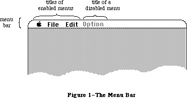 Figure 1–The Menu Bar
A menu may be temporarily disabled, so that none of the items in it can be chosen. A disabled menu can still be pulled down, but its title and all the items in it are dimmed.
The maximum number of menu titles in the menu bar is 16; however, ten to twelve titles are usually all that will fit, and you must leave at least enough room in the menu bar for one desk accessory menu. Also keep in mind that if your program is likely to be translated into other languages, the menu titles may take up more space. If you’re having trouble fitting your menus into the menu bar, you should review your menu organization and menu titles.
_______________________________________________________________________________
»Appearance of Menus
A standard menu consists of a number of menu items listed vertically inside a shadowed rectangle. A menu item may be the text of a command, or just a line dividing groups of choices (see Figure 2). An ellipsis (...) following the text of an item indicates that selecting the item will bring up a dialog box to get further information before the command is executed. Menus always appear in front of everything else (except the cursor); in Figure 2, the menu appears in front of a document window already on the screen.
Note: In the 64K ROM version of the Menu Manager, if the user attempted to
pull down an empty menu (one with no items), an unsightly empty menu
of arbitrary size was displayed. In the 128K ROM version, the menu
title is highlighted but the menu is not pulled down at all.
Figure 1–The Menu Bar
A menu may be temporarily disabled, so that none of the items in it can be chosen. A disabled menu can still be pulled down, but its title and all the items in it are dimmed.
The maximum number of menu titles in the menu bar is 16; however, ten to twelve titles are usually all that will fit, and you must leave at least enough room in the menu bar for one desk accessory menu. Also keep in mind that if your program is likely to be translated into other languages, the menu titles may take up more space. If you’re having trouble fitting your menus into the menu bar, you should review your menu organization and menu titles.
_______________________________________________________________________________
»Appearance of Menus
A standard menu consists of a number of menu items listed vertically inside a shadowed rectangle. A menu item may be the text of a command, or just a line dividing groups of choices (see Figure 2). An ellipsis (...) following the text of an item indicates that selecting the item will bring up a dialog box to get further information before the command is executed. Menus always appear in front of everything else (except the cursor); in Figure 2, the menu appears in front of a document window already on the screen.
Note: In the 64K ROM version of the Menu Manager, if the user attempted to
pull down an empty menu (one with no items), an unsightly empty menu
of arbitrary size was displayed. In the 128K ROM version, the menu
title is highlighted but the menu is not pulled down at all.
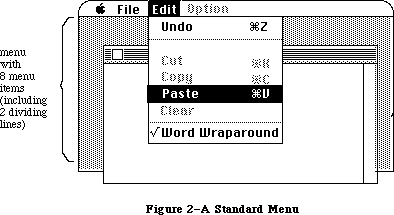 Figure 2–A Standard Menu
The text of a menu item always appears in the system font and the system font size. Each item can have a few visual variations from the standard appearance:
• An icon to the left of the item’s text, to give a symbolic representation
of the item’s meaning or effect.
• A check mark or other character to the left of the item’s text (or icon,
if any), to denote the status of the item or of the mode it controls.
• The Command key symbol and another character to the right of the item’s
text, to show that the item may be invoked from the keyboard (that is,
it has a keyboard equivalent). Pressing this key while holding down the
Command key invokes the item just as if it had been chosen from the menu
(see “Keyboard Equivalents for Commands” below).
• A character style other than the standard, such as bold, italic,
underline, or a combination of these. (The QuickDraw chapter gives a
full discussion of character style.)
• A dimmed appearance, to indicate that the item is disabled, and can’t
be chosen. The Cut, Copy, and Clear commands in Figure 2 are disabled;
dividing lines are always disabled.
Note: Special symbols or icons may have an unusual appearance when dimmed;
notice the dimmed Command symbol in the Cut and Copy menu items in
Figure 2.
If the standard menu doesn’t suit your needs—for example, if you want more graphics, or perhaps a nonlinear text arrangement—you can define a custom menu that, although visibly different to the user, responds to your application’s Menu Manager calls just like a standard menu.
_______________________________________________________________________________
»Hierarchical Menus
A hierarchical menu is a menu that includes, among its various menu choices, the ability to display a submenu. In most cases the submenu appears to the right of the menu item used to select it, and is marked with a filled triangle indicator. Throughout this chapter, there is a distinction made between a menu and a hierarchical menu. If the word hierarchical is not used, then the reference is to a nonhierarchical menu. At times, though, the term normal or regular menu may appear when referring to a nonhierarchical menu. The term submenu is used to describe any menu that is the “offspring” of a previous menu.
Several illustrations of hierarchical menus appear in the Macintosh User Interface Guidelines chapter, with recommendations for their use.
_______________________________________________________________________________
»Pop-Up Menus
The PopUpMenuSelect routine allows an application to create a pop-up menu. A pop-up menu is one that isn’t in the menu bar, but appears somewhere else on the screen (usually in a dialog box) when the user presses in a particular place. A pop-up menu may be colored like any other menu, and it may have submenus. Pop-up menus are typically used for lists of items, for example, a list of fonts. See the Macintosh User Interface Guidelines chapter for a more complete description of how to use pop-up menus in your application.
_______________________________________________________________________________
»Color Menus
For the Macintosh II, color can be added to menus in video modes with a resolution of two bits or greater. Your application can specify the menu bar color, menu title colors, the background color of a pulled down menu, and a separate color for each menu item’s mark, name, and command character. As the Macintosh II is shipped, the only user observable menu color is the color Apple symbol, which appears in the 4-bit and 8-bit modes. If the menu title is the appleMark (a one-character string containing the appleMark character $14) the color Apple symbol appears instead of the system font appleMark.
Multicolor menus should be used with discretion: user testing has shown that the use of many arbitrary colors can cause user confusion and slow down menu item recognition. See the Macintosh User Interface Guidelines chapter for more information on using color in applications.
The user can specify system-wide menu colors along with a colored desktop pattern with the Control Panel, and applications should avoid overriding the user choices. The system-wide menu colors are specified in the 'mctb'
resource = 0 in the System file, and include
• the menu bar color
• a default color for menu titles
• a default color for the background of a pulled-down menu
• a default color for menu items.
The user-specified default colors may be overridden by a separate 'mctb' resource = 0 in the application’s resource file.
Of course, a user can also use a resource editor to completely color an application’s menus by adding or changing its 'mctb' resource(s). If your application doesn’t need color menus, it should not try to override the user’s default color choices. However, if the application needs specific colors that might clash with a user’s default choices, the user should be prompted for an alternate choice of colors. An application should only override a user’s choices as a last resort; let the user’s color preferences prevail.
_______________________________________________________________________________
»Keyboard Equivalents for Commands
Your program can set up a keyboard equivalent for any of its menu commands so the command can be invoked from the keyboard with the Command key. The character you specify for a keyboard equivalent will usually be a letter. The user can type the letter in either uppercase or lowercase. For example, typing either “C” or “c” while holding down the Command key invokes the command whose equivalent is “C”.
Note: For consistency between applications, you should specify the letter
in uppercase in the menu.
You can specify characters other than letters for keyboard equivalents. However, the Shift key will be ignored when the equivalent is typed, so you shouldn’t specify shifted characters. For example, when the user types Command-+, the system reads it as Command-=.
Command-Shift-number combinations are not keyboard equivalents. They’re detected and handled by the Toolbox Event Manager function GetNextEvent, and are never returned to your program. (This is how disk ejection with Command-Shift-1 or 2 is implemented.) Although it’s possible to use unshifted Command-number combinations as keyboard equivalents, you shouldn’t do so, to avoid confusion.
Warning: You must use the standard keyboard equivalents Z, X, C, and V for
the editing commands Undo, Cut, Copy, and Paste, or editing won’t
work correctly in desk accessories.
_______________________________________________________________________________
»MENUS AND RESOURCES
_______________________________________________________________________________
The general appearance and behavior of a menu is determined by a routine called its menu definition procedure, which is stored as a resource in a resource file. The menu definition procedure performs all actions that differ from one menu type to another, such as drawing the menu. The Menu Manager calls the menu definition procedure whenever it needs to perform one of these basic actions, passing it a message that tells which action to perform.
The standard menu definition procedure is part of the system resource file. It lists the menu items vertically, and each item may have an icon, a check mark or other symbol, a keyboard equivalent, a different character style, or a dimmed appearance. If you want to define your own, nonstandard menu types,
you’ll have to write menu definition procedures for them, as described later in the section “Defining Your Own Menus”.
You can also use a resource file to store the contents of your application’s menus. This allows the menus to be edited or translated to another language without affecting the application’s source code. The Menu Manager lets you read complete menu bars as well as individual menus from a resource file.
Warning: Menu resources should never be marked as purgeable. If a Menu
Manager routine tries to access a menu that’s been purged, a
system error (ID 84) will occur.
Even if you don’t store entire menus in resource files, it’s a good idea to store the text strings they contain as resources; you can call the Resource Manager directly to read them in. Icons in menus are read from resource files; the Menu Manager calls the Resource Manager to read in the icons.
There’s a Menu Manager procedure that scans all open resource files for resources of a given type and installs the names of all available resources of that type into a given menu. This is how you fill a menu with the names of all available desk accessories or fonts, for example.
Note: If you use a menu of this type, check to make sure that at least one
item is in the menu; if not, you should put a disabled item in it that
says “None” (or something else indicating the menu is empty).
_______________________________________________________________________________
»MENU MANAGER DATA STRUCTURES
_______________________________________________________________________________
The Menu Manager keeps all the information it needs for its operations on a particular menu in a menu record. The menu record contains the following:
• The menu ID, a number that identifies the menu. The menu ID can be the
same number as the menu’s resource ID, though it doesn’t have to be.
• The menu title.
• The contents of the menu—the text and other parts of each item.
• The horizontal and vertical dimensions of the menu, in pixels. The menu
items appear inside the rectangle formed by these dimensions; the black
border and shadow of the menu appear outside that rectangle.
• A handle to the menu definition procedure.
• Flags telling whether each menu item is enabled or disabled, and whether
the menu itself is enabled or disabled.
The data type for a menu record is called MenuInfo. A menu record is referred to by a handle:
TYPE MenuPtr = ^MenuInfo;
MenuHandle = ^MenuPtr;
You can store into and access all the necessary fields of a menu record with Menu Manager routines, so normally you don’t have to know the exact field names. However, if you want more information about the exact structure of a menu record—if you’re defining your own menu types, for instance—it’s given below.
_______________________________________________________________________________
»The MenuInfo Data Type
The type MenuInfo is defined as follows:
TYPE MenuInfo = RECORD
menuID: INTEGER; {menu ID}
menuWidth: INTEGER; {menu width in pixels}
menuHeight: INTEGER; {menu height in pixels}
menuProc: Handle; {menu definition procedure}
enableFlags: LONGINT; {tells if menu or items are enabled}
menuData: Str255 {menu title (and other data)}
END;
The menuID field contains the menu ID. MenuWidth and menuHeight are the menu’s horizontal and vertical dimensions in pixels. MenuProc is a handle to the menu definition procedure for this type of menu.
Bit 0 of the enableFlags field is 1 if the menu is enabled, or 0 if it’s disabled. Bits 1 to 31 similarly tell whether each item in the menu is enabled or disabled.
The menuData field contains the menu title followed by variable-length data that defines the text and other parts of the menu items. The Str255 data type enables you to access the title from Pascal; there’s actually additional data beyond the title that’s inaccessible from Pascal and is not reflected in the MenuInfo data structure.
Warning: You can read the menu title directly from the menuData field, but
do not change the title directly, or the data defining the menu
items may be destroyed.
_______________________________________________________________________________
»Menu Lists
A menu list contains handles to one or more menus, along with information about the position of each menu in the menu bar. The current menu list contains handles to all the menus currently in the menu bar; the menu bar shows the titles, in order, of all menus in the menu list. When you initialize the Menu Manager, it allocates space for the maximum-size menu list.
The Menu Manager provides all the necessary routines for manipulating the current menu list, so there’s no need to access it directly yourself. As a general rule, routines that deal specifically with menus in the menu list use the menu ID to refer to menus; those that deal with any menus, whether in the menu list or not, use the menu handle to refer to menus. Some routines refer to the menu list as a whole, with a handle.
Assembly-language note: The global variable MenuList contains a handle to
the current menu list. The menu list has the format
shown below.
Number of bytes Contents
2 bytes Offset from beginning of menu list
to last menu handle (the number of
menus in the list times 6)
2 bytes Horizontal coordinate of right edge
of menu title of last menu in list
2 bytes Not used
For each menu:
4 bytes Menu handle
2 bytes Horizontal coordinate of left edge
of menu
For backward compatibility, the MenuInfo structure has not been changed, although several of its fields have new meanings for hierarchical menus. The MenuList has also kept its general structure to provide backward compatibility, and still contains six bytes of header information and six bytes of information for each menu; however, each menu entry is now allocated dynamically. There is also additional storage at the end of the MenuList for hierarchical and pop-up menus.
Except where explicitly noted, the data structures in the following section are listed for information only; applications should never interrogate or change them directly. The Menu Manager routines provide all needed functions.
_______________________________________________________________________________
»Data Structures for Hierarchical Menus
A new MenuList data structure accommodates hierarchical menus. It dynamically allocates storage space as menus and hierarchical menus are added and deleted.
Warning: The MenuList data structure is listed for information only;
applications should never access it directly.
The following TYPE definition is for conceptual purposes only; there is no such data structure in the Menu Manager:
TYPE InitialMenuList = RECORD
lastMenu: INTEGER; {offset}
lastRight: INTEGER; {pixels}
mbResID: INTEGER; {upper 13 bits used as }
{ mbarproc resource ID }
{ low 3 bits used as }
{ mbVariant }
lastHMenu: INTEGER; {offset}
menuTitleSave: pixMapHandle {handle to bits behind}
{ inverted menu title}
END;
Field descriptions
lastMenu The lastMenu field contains the offset to the last regular
menu in the MenuList.
lastRight The lastRight field contains the pixel location of the right
edge of the rightmost menu in the menu bar.
mbResID The mbResID field stores the resource ID of the menu bar defproc
used by the application. Its default value is zero. The upper 13
bits are used as the resource ID. The low three bits are passed
to the menu bar defproc ('MBDF') as the mbVariant.
lastHMenu The lastHMenu field contains the offset to the last
hierarchical menu in the MenuList.
menuTitleSave The menuTitleSave field stores a PixMapHandle to the saved
“bits behind” the selected menu title.
When the MenuList data structure is initialized, there is no space allocated for menu handles or hierarchical menu handles. When a menu is allocated, six bytes are inserted between the mbResID and lastHMenu fields. As each menu is allocated or deleted, the space between mbResID and lastHMenu grows or shrinks accordingly. Space is allocated for hierarchical menus after the MenuTitleSave field, and its space is also dynamic.
A sample MenuList Data Structure with X menus and Y hierarchical menus appears below.
Warning: The sample MenuList structure is not a valid Pascal type because
of its dynamic size; it’s shown for conceptual purposes only.
TYPE MenuRec = RECORD
menuOH: Menuhandle; {menu's data}
menuLeft: INTEGER; {pixels}
END;
HMenuRec = RECORD
menuHOH: Menuhandle; {hierarchical menu's data}
reserved: INTEGER; {reserved for future use}
END;
DynamicMenuList = RECORD
lastMenu: INTEGER; {offset}
lastRight: INTEGER; {pixels}
mbResID: INTEGER;
menu: ARRAY [1..X] OF MenuRec;
{X is the number of menus}
lastHMenu: INTEGER; {offset}
menuTitleSave: PixMapHandle {handle to bits behind }
{ inverted menu title}
hMenu: ARRAY [1..Y] OF HMenuRec;
{Y is the number of }
{ submenus used}
END;
The initial MenuList data structure is allocated by InitMenus each time an application is started. Any subsequent calls to InitMenus, while the application is running, don’t cause the MenuList data structure to be reallocated.
The MenuInfo data structure is shown below; this version is similar to what is shown earlier in this section, but includes additional information about menu items.
Warning: The MenuInfo data structure is listed for information only;
applications should never access it directly. This structure is
not a valid Pascal type because of its dynamic size; it’s shown
for conceptual purposes only.
TYPE MenuInfo = RECORD
menuID: INTEGER; {menu ID}
menuWidth: INTEGER; {pixels}
menuHeight: INTEGER; {pixels}
menuProc: Handle; {handle}
enableFlags: LONGINT; {bit string}
menuTitle: String; {menu title name}
itemData: ARRAY [1..X] OF
itemString: string; {item name}
itemIcon: BYTE; {iconnum-256}
itemCmd: char; {item cmd key}
itemMark: char; {item mark is a byte}
{ value for }
{ hierachical menus}
itemStyle: Style; {bit string}
endMarker: Byte; {zero-length string }
{ indicates no more }
{ menu items}
END;
Field descriptions
menuID The menuID field contains the menu ID of the menu.
menuWidth The menuWidth field contains the width in pixels of the menu.
menuHeight The menuHeight field contains the height in pixels of the menu.
menuProc The menuProc field contains a handle to the menu’s definition
procedure.
enableFlags The enableFlags field is a bit string which allows the menu and
the first 31 items to be enabled or disabled. All items beyond
31 are always enabled.
menuTitle The menuTitle field is a string containing the menu title.
itemData The itemData field is an array containing the following
information for each menu item: item name, item icon number,
item command key equivalent, item mark, and item style. For
hierarchical menus, the itemMark field is a byte value.
endMarker The endMarker field is a byte value, which contains zero if
there are no more menu items.
The contents of the itemData array are the same for hierarchical and nonhierarchical menus, but for hierarchical menus the itemMark field is a byte value, which limits hierarchical menu menuID values to between 0 and 255. Hierarchical menus numbered 236 to 255 are reserved for use by desk accessories. Desk accessories must remove their hierarchical menus from the MenuList each time their window is not the frontmost, to prevent hierarchical menu collisions with other desk accessories.
_______________________________________________________________________________
»Color Menu Data Structures
For the Macintosh II, menus can be colored in 2-bit mode or higher, in both color and gray-scale. The menu color information is contained in a table format, but because this format is different from the standard color table format, it is referred to as the menu color information table, rather than the menu color table. A menu color information table is composed of several entries, each of which is an MCEntry record. These data structures are shown below:
TYPE MCEntryPtr = ^MCEntry;
MCEntry = RECORD
mctID: INTEGER; {menu ID. ID = 0 is }
{ the menu bar}
mctItem: INTEGER; {menu entry. Item = 0 }
{ is a title}
mctRGB1: RGBColor; {usage depends on ID and Item}
mctRGB2: RGBColor; {usage depends on ID and Item}
mctRGB3: RGBColor; {usage depends on ID and Item}
mctRGB4: RGBColor; {usage depends on ID and Item}
mctReserved: INTEGER; {reserved for internal use}
END;
MCTable = ARRAY [0..0] of MCEntry; {The menu entries are }
{ represented in this array}
MCTablePtr = ^MCTable;
MCTableHandle = ^MCTablePtr;
Field descriptions
mctID The mctID field contains the menu ID of the menu. A value of
mctID = 0 means that this is the menu bar.
mctItem The mctItem field contains the menu item. A value of item = 0
means that the item is a menu title.
mctRGB1 The mctRGB1 field contains a color value which depends on the
mctID and mctItem. See the description in the following section.
mctRGB2 The mctRGB2 field contains a color value which depends on the
mctID and mctItem. See the description in the following section.
mctRGB3 The mctRGB3 field contains a color value which depends on the
mctID and mctItem. See the description in the following section.
mctRGB4 The mctRGB4 field contains a color value which depends on the
mctID and mctItem. See the description in the following section.
mctReserved The mctReserved field is used internally; applications must not
use this field.
The color information table is created at InitMenus time, and its handle is stored in the global variable MenuCInfo ($D50). Like the MenuList data structure, it is only created the first time InitMenus or InitProcMenu is called for an application.
A menu color information table is shown in Figure 3.
Figure 2–A Standard Menu
The text of a menu item always appears in the system font and the system font size. Each item can have a few visual variations from the standard appearance:
• An icon to the left of the item’s text, to give a symbolic representation
of the item’s meaning or effect.
• A check mark or other character to the left of the item’s text (or icon,
if any), to denote the status of the item or of the mode it controls.
• The Command key symbol and another character to the right of the item’s
text, to show that the item may be invoked from the keyboard (that is,
it has a keyboard equivalent). Pressing this key while holding down the
Command key invokes the item just as if it had been chosen from the menu
(see “Keyboard Equivalents for Commands” below).
• A character style other than the standard, such as bold, italic,
underline, or a combination of these. (The QuickDraw chapter gives a
full discussion of character style.)
• A dimmed appearance, to indicate that the item is disabled, and can’t
be chosen. The Cut, Copy, and Clear commands in Figure 2 are disabled;
dividing lines are always disabled.
Note: Special symbols or icons may have an unusual appearance when dimmed;
notice the dimmed Command symbol in the Cut and Copy menu items in
Figure 2.
If the standard menu doesn’t suit your needs—for example, if you want more graphics, or perhaps a nonlinear text arrangement—you can define a custom menu that, although visibly different to the user, responds to your application’s Menu Manager calls just like a standard menu.
_______________________________________________________________________________
»Hierarchical Menus
A hierarchical menu is a menu that includes, among its various menu choices, the ability to display a submenu. In most cases the submenu appears to the right of the menu item used to select it, and is marked with a filled triangle indicator. Throughout this chapter, there is a distinction made between a menu and a hierarchical menu. If the word hierarchical is not used, then the reference is to a nonhierarchical menu. At times, though, the term normal or regular menu may appear when referring to a nonhierarchical menu. The term submenu is used to describe any menu that is the “offspring” of a previous menu.
Several illustrations of hierarchical menus appear in the Macintosh User Interface Guidelines chapter, with recommendations for their use.
_______________________________________________________________________________
»Pop-Up Menus
The PopUpMenuSelect routine allows an application to create a pop-up menu. A pop-up menu is one that isn’t in the menu bar, but appears somewhere else on the screen (usually in a dialog box) when the user presses in a particular place. A pop-up menu may be colored like any other menu, and it may have submenus. Pop-up menus are typically used for lists of items, for example, a list of fonts. See the Macintosh User Interface Guidelines chapter for a more complete description of how to use pop-up menus in your application.
_______________________________________________________________________________
»Color Menus
For the Macintosh II, color can be added to menus in video modes with a resolution of two bits or greater. Your application can specify the menu bar color, menu title colors, the background color of a pulled down menu, and a separate color for each menu item’s mark, name, and command character. As the Macintosh II is shipped, the only user observable menu color is the color Apple symbol, which appears in the 4-bit and 8-bit modes. If the menu title is the appleMark (a one-character string containing the appleMark character $14) the color Apple symbol appears instead of the system font appleMark.
Multicolor menus should be used with discretion: user testing has shown that the use of many arbitrary colors can cause user confusion and slow down menu item recognition. See the Macintosh User Interface Guidelines chapter for more information on using color in applications.
The user can specify system-wide menu colors along with a colored desktop pattern with the Control Panel, and applications should avoid overriding the user choices. The system-wide menu colors are specified in the 'mctb'
resource = 0 in the System file, and include
• the menu bar color
• a default color for menu titles
• a default color for the background of a pulled-down menu
• a default color for menu items.
The user-specified default colors may be overridden by a separate 'mctb' resource = 0 in the application’s resource file.
Of course, a user can also use a resource editor to completely color an application’s menus by adding or changing its 'mctb' resource(s). If your application doesn’t need color menus, it should not try to override the user’s default color choices. However, if the application needs specific colors that might clash with a user’s default choices, the user should be prompted for an alternate choice of colors. An application should only override a user’s choices as a last resort; let the user’s color preferences prevail.
_______________________________________________________________________________
»Keyboard Equivalents for Commands
Your program can set up a keyboard equivalent for any of its menu commands so the command can be invoked from the keyboard with the Command key. The character you specify for a keyboard equivalent will usually be a letter. The user can type the letter in either uppercase or lowercase. For example, typing either “C” or “c” while holding down the Command key invokes the command whose equivalent is “C”.
Note: For consistency between applications, you should specify the letter
in uppercase in the menu.
You can specify characters other than letters for keyboard equivalents. However, the Shift key will be ignored when the equivalent is typed, so you shouldn’t specify shifted characters. For example, when the user types Command-+, the system reads it as Command-=.
Command-Shift-number combinations are not keyboard equivalents. They’re detected and handled by the Toolbox Event Manager function GetNextEvent, and are never returned to your program. (This is how disk ejection with Command-Shift-1 or 2 is implemented.) Although it’s possible to use unshifted Command-number combinations as keyboard equivalents, you shouldn’t do so, to avoid confusion.
Warning: You must use the standard keyboard equivalents Z, X, C, and V for
the editing commands Undo, Cut, Copy, and Paste, or editing won’t
work correctly in desk accessories.
_______________________________________________________________________________
»MENUS AND RESOURCES
_______________________________________________________________________________
The general appearance and behavior of a menu is determined by a routine called its menu definition procedure, which is stored as a resource in a resource file. The menu definition procedure performs all actions that differ from one menu type to another, such as drawing the menu. The Menu Manager calls the menu definition procedure whenever it needs to perform one of these basic actions, passing it a message that tells which action to perform.
The standard menu definition procedure is part of the system resource file. It lists the menu items vertically, and each item may have an icon, a check mark or other symbol, a keyboard equivalent, a different character style, or a dimmed appearance. If you want to define your own, nonstandard menu types,
you’ll have to write menu definition procedures for them, as described later in the section “Defining Your Own Menus”.
You can also use a resource file to store the contents of your application’s menus. This allows the menus to be edited or translated to another language without affecting the application’s source code. The Menu Manager lets you read complete menu bars as well as individual menus from a resource file.
Warning: Menu resources should never be marked as purgeable. If a Menu
Manager routine tries to access a menu that’s been purged, a
system error (ID 84) will occur.
Even if you don’t store entire menus in resource files, it’s a good idea to store the text strings they contain as resources; you can call the Resource Manager directly to read them in. Icons in menus are read from resource files; the Menu Manager calls the Resource Manager to read in the icons.
There’s a Menu Manager procedure that scans all open resource files for resources of a given type and installs the names of all available resources of that type into a given menu. This is how you fill a menu with the names of all available desk accessories or fonts, for example.
Note: If you use a menu of this type, check to make sure that at least one
item is in the menu; if not, you should put a disabled item in it that
says “None” (or something else indicating the menu is empty).
_______________________________________________________________________________
»MENU MANAGER DATA STRUCTURES
_______________________________________________________________________________
The Menu Manager keeps all the information it needs for its operations on a particular menu in a menu record. The menu record contains the following:
• The menu ID, a number that identifies the menu. The menu ID can be the
same number as the menu’s resource ID, though it doesn’t have to be.
• The menu title.
• The contents of the menu—the text and other parts of each item.
• The horizontal and vertical dimensions of the menu, in pixels. The menu
items appear inside the rectangle formed by these dimensions; the black
border and shadow of the menu appear outside that rectangle.
• A handle to the menu definition procedure.
• Flags telling whether each menu item is enabled or disabled, and whether
the menu itself is enabled or disabled.
The data type for a menu record is called MenuInfo. A menu record is referred to by a handle:
TYPE MenuPtr = ^MenuInfo;
MenuHandle = ^MenuPtr;
You can store into and access all the necessary fields of a menu record with Menu Manager routines, so normally you don’t have to know the exact field names. However, if you want more information about the exact structure of a menu record—if you’re defining your own menu types, for instance—it’s given below.
_______________________________________________________________________________
»The MenuInfo Data Type
The type MenuInfo is defined as follows:
TYPE MenuInfo = RECORD
menuID: INTEGER; {menu ID}
menuWidth: INTEGER; {menu width in pixels}
menuHeight: INTEGER; {menu height in pixels}
menuProc: Handle; {menu definition procedure}
enableFlags: LONGINT; {tells if menu or items are enabled}
menuData: Str255 {menu title (and other data)}
END;
The menuID field contains the menu ID. MenuWidth and menuHeight are the menu’s horizontal and vertical dimensions in pixels. MenuProc is a handle to the menu definition procedure for this type of menu.
Bit 0 of the enableFlags field is 1 if the menu is enabled, or 0 if it’s disabled. Bits 1 to 31 similarly tell whether each item in the menu is enabled or disabled.
The menuData field contains the menu title followed by variable-length data that defines the text and other parts of the menu items. The Str255 data type enables you to access the title from Pascal; there’s actually additional data beyond the title that’s inaccessible from Pascal and is not reflected in the MenuInfo data structure.
Warning: You can read the menu title directly from the menuData field, but
do not change the title directly, or the data defining the menu
items may be destroyed.
_______________________________________________________________________________
»Menu Lists
A menu list contains handles to one or more menus, along with information about the position of each menu in the menu bar. The current menu list contains handles to all the menus currently in the menu bar; the menu bar shows the titles, in order, of all menus in the menu list. When you initialize the Menu Manager, it allocates space for the maximum-size menu list.
The Menu Manager provides all the necessary routines for manipulating the current menu list, so there’s no need to access it directly yourself. As a general rule, routines that deal specifically with menus in the menu list use the menu ID to refer to menus; those that deal with any menus, whether in the menu list or not, use the menu handle to refer to menus. Some routines refer to the menu list as a whole, with a handle.
Assembly-language note: The global variable MenuList contains a handle to
the current menu list. The menu list has the format
shown below.
Number of bytes Contents
2 bytes Offset from beginning of menu list
to last menu handle (the number of
menus in the list times 6)
2 bytes Horizontal coordinate of right edge
of menu title of last menu in list
2 bytes Not used
For each menu:
4 bytes Menu handle
2 bytes Horizontal coordinate of left edge
of menu
For backward compatibility, the MenuInfo structure has not been changed, although several of its fields have new meanings for hierarchical menus. The MenuList has also kept its general structure to provide backward compatibility, and still contains six bytes of header information and six bytes of information for each menu; however, each menu entry is now allocated dynamically. There is also additional storage at the end of the MenuList for hierarchical and pop-up menus.
Except where explicitly noted, the data structures in the following section are listed for information only; applications should never interrogate or change them directly. The Menu Manager routines provide all needed functions.
_______________________________________________________________________________
»Data Structures for Hierarchical Menus
A new MenuList data structure accommodates hierarchical menus. It dynamically allocates storage space as menus and hierarchical menus are added and deleted.
Warning: The MenuList data structure is listed for information only;
applications should never access it directly.
The following TYPE definition is for conceptual purposes only; there is no such data structure in the Menu Manager:
TYPE InitialMenuList = RECORD
lastMenu: INTEGER; {offset}
lastRight: INTEGER; {pixels}
mbResID: INTEGER; {upper 13 bits used as }
{ mbarproc resource ID }
{ low 3 bits used as }
{ mbVariant }
lastHMenu: INTEGER; {offset}
menuTitleSave: pixMapHandle {handle to bits behind}
{ inverted menu title}
END;
Field descriptions
lastMenu The lastMenu field contains the offset to the last regular
menu in the MenuList.
lastRight The lastRight field contains the pixel location of the right
edge of the rightmost menu in the menu bar.
mbResID The mbResID field stores the resource ID of the menu bar defproc
used by the application. Its default value is zero. The upper 13
bits are used as the resource ID. The low three bits are passed
to the menu bar defproc ('MBDF') as the mbVariant.
lastHMenu The lastHMenu field contains the offset to the last
hierarchical menu in the MenuList.
menuTitleSave The menuTitleSave field stores a PixMapHandle to the saved
“bits behind” the selected menu title.
When the MenuList data structure is initialized, there is no space allocated for menu handles or hierarchical menu handles. When a menu is allocated, six bytes are inserted between the mbResID and lastHMenu fields. As each menu is allocated or deleted, the space between mbResID and lastHMenu grows or shrinks accordingly. Space is allocated for hierarchical menus after the MenuTitleSave field, and its space is also dynamic.
A sample MenuList Data Structure with X menus and Y hierarchical menus appears below.
Warning: The sample MenuList structure is not a valid Pascal type because
of its dynamic size; it’s shown for conceptual purposes only.
TYPE MenuRec = RECORD
menuOH: Menuhandle; {menu's data}
menuLeft: INTEGER; {pixels}
END;
HMenuRec = RECORD
menuHOH: Menuhandle; {hierarchical menu's data}
reserved: INTEGER; {reserved for future use}
END;
DynamicMenuList = RECORD
lastMenu: INTEGER; {offset}
lastRight: INTEGER; {pixels}
mbResID: INTEGER;
menu: ARRAY [1..X] OF MenuRec;
{X is the number of menus}
lastHMenu: INTEGER; {offset}
menuTitleSave: PixMapHandle {handle to bits behind }
{ inverted menu title}
hMenu: ARRAY [1..Y] OF HMenuRec;
{Y is the number of }
{ submenus used}
END;
The initial MenuList data structure is allocated by InitMenus each time an application is started. Any subsequent calls to InitMenus, while the application is running, don’t cause the MenuList data structure to be reallocated.
The MenuInfo data structure is shown below; this version is similar to what is shown earlier in this section, but includes additional information about menu items.
Warning: The MenuInfo data structure is listed for information only;
applications should never access it directly. This structure is
not a valid Pascal type because of its dynamic size; it’s shown
for conceptual purposes only.
TYPE MenuInfo = RECORD
menuID: INTEGER; {menu ID}
menuWidth: INTEGER; {pixels}
menuHeight: INTEGER; {pixels}
menuProc: Handle; {handle}
enableFlags: LONGINT; {bit string}
menuTitle: String; {menu title name}
itemData: ARRAY [1..X] OF
itemString: string; {item name}
itemIcon: BYTE; {iconnum-256}
itemCmd: char; {item cmd key}
itemMark: char; {item mark is a byte}
{ value for }
{ hierachical menus}
itemStyle: Style; {bit string}
endMarker: Byte; {zero-length string }
{ indicates no more }
{ menu items}
END;
Field descriptions
menuID The menuID field contains the menu ID of the menu.
menuWidth The menuWidth field contains the width in pixels of the menu.
menuHeight The menuHeight field contains the height in pixels of the menu.
menuProc The menuProc field contains a handle to the menu’s definition
procedure.
enableFlags The enableFlags field is a bit string which allows the menu and
the first 31 items to be enabled or disabled. All items beyond
31 are always enabled.
menuTitle The menuTitle field is a string containing the menu title.
itemData The itemData field is an array containing the following
information for each menu item: item name, item icon number,
item command key equivalent, item mark, and item style. For
hierarchical menus, the itemMark field is a byte value.
endMarker The endMarker field is a byte value, which contains zero if
there are no more menu items.
The contents of the itemData array are the same for hierarchical and nonhierarchical menus, but for hierarchical menus the itemMark field is a byte value, which limits hierarchical menu menuID values to between 0 and 255. Hierarchical menus numbered 236 to 255 are reserved for use by desk accessories. Desk accessories must remove their hierarchical menus from the MenuList each time their window is not the frontmost, to prevent hierarchical menu collisions with other desk accessories.
_______________________________________________________________________________
»Color Menu Data Structures
For the Macintosh II, menus can be colored in 2-bit mode or higher, in both color and gray-scale. The menu color information is contained in a table format, but because this format is different from the standard color table format, it is referred to as the menu color information table, rather than the menu color table. A menu color information table is composed of several entries, each of which is an MCEntry record. These data structures are shown below:
TYPE MCEntryPtr = ^MCEntry;
MCEntry = RECORD
mctID: INTEGER; {menu ID. ID = 0 is }
{ the menu bar}
mctItem: INTEGER; {menu entry. Item = 0 }
{ is a title}
mctRGB1: RGBColor; {usage depends on ID and Item}
mctRGB2: RGBColor; {usage depends on ID and Item}
mctRGB3: RGBColor; {usage depends on ID and Item}
mctRGB4: RGBColor; {usage depends on ID and Item}
mctReserved: INTEGER; {reserved for internal use}
END;
MCTable = ARRAY [0..0] of MCEntry; {The menu entries are }
{ represented in this array}
MCTablePtr = ^MCTable;
MCTableHandle = ^MCTablePtr;
Field descriptions
mctID The mctID field contains the menu ID of the menu. A value of
mctID = 0 means that this is the menu bar.
mctItem The mctItem field contains the menu item. A value of item = 0
means that the item is a menu title.
mctRGB1 The mctRGB1 field contains a color value which depends on the
mctID and mctItem. See the description in the following section.
mctRGB2 The mctRGB2 field contains a color value which depends on the
mctID and mctItem. See the description in the following section.
mctRGB3 The mctRGB3 field contains a color value which depends on the
mctID and mctItem. See the description in the following section.
mctRGB4 The mctRGB4 field contains a color value which depends on the
mctID and mctItem. See the description in the following section.
mctReserved The mctReserved field is used internally; applications must not
use this field.
The color information table is created at InitMenus time, and its handle is stored in the global variable MenuCInfo ($D50). Like the MenuList data structure, it is only created the first time InitMenus or InitProcMenu is called for an application.
A menu color information table is shown in Figure 3.
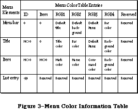 Figure 3–Menu Color Information Table
There is always at least one entry in the color table, the last entry, which has the arbitrary value –99 in the ID field as an “end-of-table” marker. (This means that the value –99 cannot be used as an ID by an application.) Note that the other fields in the “end-of-table” entry are reserved by use for Apple. Each entry in the color information table has seven fields.
The first two fields define the entry’s menu and item. The last field is used internally and has no information for use by programmers. The other fields define colors depending on what type of menu element the entry describes. All colors are specified as RGB colors. There are three types of entries in the menu color information table: one type for the menu bar, one type for menu titles, and one type for menu items.
The menu bar entry has ID = 0, Item = 0. There will be at most one menu bar entry in the color information table. If there is no menu bar entry, the default menu bar colors are black text on a white background. The fields in a menu bar entry are as follows:
• mctRGB1 is the default color for menu titles. If a menu title doesn’t
have an entry in the table, then this is the color used to draw the title.
• mctRGB2 is the default color for the background of a pulled down menu.
If a menu title doesn’t have an entry in the table, this color is used
as the menu’s background color.
• mctRGB3 is the default color for the items in a pulled down menu. If a
menu item doesn’t have an entry in a table, and if the title for that
menu item doesn’t also have an entry, this color will be used to color
the mark, name, and Command-key equivalent of the item.
• mctRGB4 is the menu bar color.
The menu title entry has ID <> 0, Item = 0. There will be at most one title entry for each menu in the color information table. If there is no title entry, the title, menu background, and menu items are drawn using the defaults found in the menu bar entry. If there is no menu bar entry, the default colors are black on white. The fields in a title entry areas follows:
• mctRGBG1 is the title color.
• mctRGB2 is the menu bar color. This is duplicated here from the menu bar
entry to speed menu drawing.
• mctRGB3 is the default color for the menu items. If a menu item doesn’t
have an entry in the table, this color will be used to color the mark,
name, and Command-key equivalent of the item.
• mctRGB4 is the menu’s background color.
The menu item entry has ID <> 0, Item <> 0. There will be at most one item entry for each menu item in the color information table. If there is no entry for a particular item, the item mark, name, and Command-key equivalent are drawn using the defaults found in the title entry. If there is no title entry, the information in the menu bar entry is used. If there is no menu bar entry, the mark, name, and Command-key equivalent are drawn in black. The fields in an item entry are as follows:
• mctRGB1 is the mark color.
• mctRGB2 is the name color.
• mctRGB3 is the Command-key equivalent.
• mctRGB4 is the menu’s background color. It’s duplicated here to
speed menu drawing.
It’s not possible to specify an icon’s color. Black and white icons are drawn in the item’s name color. Icons may be colored using a 'cicn' resource instead of an 'ICON' resource. When an icon is drawn in a menu, the menu defproc attempts to load the 'cicn' resource first, and if it isn’t found, searches for the 'ICON' resource. See the QuickDraw chapter for more information on color icons.
_______________________________________________________________________________
»Menu Color Information Table Resource Format
The resource type for a menu color information table is 'mctb'. Once read into memory, this data is transferred into the application’s menu color information table. The resource data format is identical to an MCTable, with the addition of a leading word that contains the number of entries in the resource:
TYPE MenuCRsrc = RECORD
numEntries: integer;
data: array [1..numEntries] of MCEntry;
END;
The 'mctb' resource is loaded automatically by two routines. InitMenus attempts to load an 'mctb' resource = 0, and if it is successful, adds the colors to the application’s menu color information table. GetMenu attempts to load an 'mctb' resource with the same resource ID as the menu it has loaded, and if it succeeds, it adds the colors to the application’s menu color information table.
_______________________________________________________________________________
»CREATING A MENU IN YOUR PROGRAM
_______________________________________________________________________________
The best way to create your application’s menus is to set them up as resources and read them in from a resource file. If you want your application to create the menus itself, though, it must call the NewMenu and AppendMenu routines. NewMenu creates a new menu data structure, returning a handle to it. AppendMenu takes a string and a handle to a menu and adds the items in the string to the end of the menu.
The string passed to AppendMenu consists mainly of the text of the menu items. For a dividing line, use one hyphen (–); AppendMenu ignores any following characters, and draws a dotted line across the width of the menu. For a blank item, use one or more spaces. Other characters interspersed in the string have special meaning to the Menu Manager. These “meta-characters” are used in conjunction with text to separate menu items or alter their appearance (for example, you can use one to disable any dividing line or blank item). The
meta-characters aren’t displayed in the menu.
Meta-character Meaning
; or Return Separates items
^ Item has an icon
! Item has a check or other mark
< Item has a special character style
/ Item has a keyboard equivalent
( Item is disabled
None, any, or all of these meta-characters can appear in the AppendMenu string; they’re described in detail below. To add one text-only item to a menu would require a simple string without any meta-characters:
AppendMenu(thisMenu,'Just Enough')
An extreme example could use many meta-characters:
AppendMenu(thisMenu,'(Too Much^1<B/T')
This example adds to the menu an item whose text is “Too Much”, which is disabled, has icon number 1, is boldfaced, and can be invoked by Command-T. Your menu items should be much simpler than this.
Note: If you want any of the meta-characters to appear in the text of a
menu item, you can include them by changing the text with the Menu
Manager procedure SetItem.
_______________________________________________________________________________
»Multiple Items
Each call to AppendMenu can add one or many items to the menu. To add multiple items in the same call, use a semicolon (;) or a Return character to separate the items. The call
AppendMenu(thisMenu,'Cut;Copy')
has exactly the same effect as the calls
AppendMenu(thisMenu,'Cut');
AppendMenu(thisMenu,'Copy')
_______________________________________________________________________________
»Items with Icons
A circumflex (^ ) followed by a digit from 1 to 9 indicates that an icon should appear to the left of the text in the menu. The digit, called the icon number, yields the resource ID of the icon in the resource file. Icon resource IDs 257 through 511 are reserved for menu icons; thus the Menu Manager adds 256 to the icon number to get the proper resource ID.
Note: The Menu Manager gets the icon number by subtracting 48 from the ASCII
code of the character following the “^” (since, for example, the ASCII
code of “1” is 49). You can actually follow the “^” with any character
that has an ASCII code greater than 48.
You can also use the SetItemIcon procedure to install icons in a menu; it accepts any icon number from 1 to 255.
_______________________________________________________________________________
»Marked Items
You can use an exclamation point (!) to cause a check mark or any other character to be placed to the left of the text (or icon, if any). Follow the exclamation point with the character of your choice; note, however, that normally you can’t type a check mark from the keyboard. To specify a check mark, you need to take special measures: Declare a string variable to have the length of the desired AppendMenu string, and assign it that string with a space following the exclamation point. Then separately store the check mark in the position of the space.
For example, suppose you want to use AppendMenu to specify a menu item that has the text “Word Wraparound” (15 characters) and a check mark to its left. You can declare the string variable
VAR s: STRING[17];
and do the following:
s := '! Word Wraparound';
s[2] := CHR(checkMark);
AppendMenu(thisMenu,s)
The constant checkMark is defined by the Font Manager as the character code for the check mark.
Note: The Font Manager also defines constants for certain other special
characters that can’t normally be typed from the keyboard: the apple
symbol, the Command key symbol, and a diamond symbol. These symbols
can be specified in the same way as the check mark.
You can call the SetItemMark or CheckItem procedures to change or clear the mark, and the GetItemMark procedure to find out what mark, if any, is being used.
_______________________________________________________________________________
»Character Style of Items
The system font is the only font available for menus; however, you can vary the character style of menu items for clarity and distinction. The meta-character for specifying the character style of an item’s text is the less-than symbol
(<). With AppendMenu, you can assign one and only one of the stylistic variations listed below.
<B Bold
<I Italic
<U Underline
<O Outline
<S Shadow
The SetItemStyle procedure allows you to assign any combination of stylistic variations to an item. For a further discussion of character style, see the QuickDraw chapter.
_______________________________________________________________________________
»Items with Keyboard Equivalents
A slash (/) followed by a character associates that character with the item, allowing the item to be invoked from the keyboard with the Command key. The specified character (preceded by the Command key symbol) appears at the right of the item’s text in the menu.
Note: Remember to specify the character in uppercase if it’s a letter, and
not to specify other shifted characters or numbers.
Given a keyboard equivalent typed by the user, you call the MenuKey function to find out which menu item was invoked.
_______________________________________________________________________________
»Disabled Items
The meta-character that disables an item is the left parenthesis, “(”. A disabled item cannot be chosen; it appears dimmed in the menu and is not highlighted when the cursor moves over it.
Menu items that are used to separate groups of items (such as a line or a blank item) should always be disabled. For example, the call
AppendMenu(thisMenu,'Undo;(-;Cut')
adds two enabled menu items, Undo and Cut, with a disabled item consisting of a line between them.
You can change the enabled or disabled state of a menu item with the DisableItem and EnableItem procedures.
_______________________________________________________________________________
»USING THE MENU MANAGER
_______________________________________________________________________________
To use the Menu Manager, you must have previously called InitGraf to initialize QuickDraw, InitFonts to initialize the Font Manager, and InitWindows to initialize the Window Manager. The first Menu Manager routine to call is the initialization procedure InitMenus.
Your application can set up the menus it needs in any number of ways:
• Read an entire prepared menu list from a resource file with
GetNewMBar, and place it in the menu bar with SetMenuBar.
• Read the menus individually from a resource file using GetMenu,
and place them in the menu bar using InsertMenu.
• Allocate the menus with NewMenu, fill them with items using
AppendMenu, and place them in the menu bar using InsertMenu.
• Allocate a menu with NewMenu, fill it with items using AddResMenu
to get the names of all available resources of a given type, and
place the menu in the menu bar using InsertMenu.
You can use AddResMenu or InsertResMenu to add items from resource files to any menu, regardless of how you created the menu or whether it already contains any items.
When you no longer need a menu, call the Resource Manager procedure ReleaseResource if you read the menu from a resource file, or DisposeMenu if you allocated it with NewMenu.
Note: If you want to save changes made to a menu that was read from a
resource file, write it back to the resource file before calling
ReleaseResource.
If you call NewMenu to allocate a menu, it will store a handle to the standard menu definition procedure in the menu record, so if you want the menu to be one you’ve designed, you must replace that handle with a handle to your own menu definition procedure. For more information, see “Defining Your Own Menus”.
After setting up the menu bar, you need to draw it with the DrawMenuBar procedure.
You can use the SetItem and GetItem procedures to change or examine a menu
item’s text at any time—for example, to change between the two forms of a toggled command. You can set or examine an item’s icon, style, or mark with the procedures SetItemIcon, GetItemIcon, SetItemStyle, GetItemStyle, CheckItem, SetItemMark, and GetItemMark. Individual items or whole menus can be enabled or disabled with the EnableItem and DisableItem procedures. You can change the number of menus in the menu list with InsertMenu or DeleteMenu, remove all the menus with ClearMenuBar, or change the entire menu list with GetNewMBar or GetMenuBar followed by SetMenuBar.
When your application receives a mouse-down event, and the Window Manager’s FindWindow function returns the predefined constant inMenuBar, your application should call the Menu Manager’s MenuSelect function, supplying it with the point where the mouse button was pressed. MenuSelect will pull down the appropriate menu, and retain control—tracking the mouse, highlighting menu items, and pulling down other menus—until the user releases the mouse button. MenuSelect returns a long integer to the application: The high-order word contains the menu ID of the menu that was chosen, and the low-order word contains the menu item number of the item that was chosen. The menu item number is the index, starting from 1, of the item in the menu. If no item was chosen, the high-order word of the long integer is 0, and the low-order word is undefined.
• If the high-order word of the long integer returned is 0, the application
should just continue to poll for further events.
• If the high-order word is nonzero, the application should invoke the menu
item specified by the low-order word, in the menu specified by the
high-order word. Only after the action is completely finished (after all
dialogs, alerts, or screen actions have been taken care of) should the
application remove the highlighting from the menu bar by calling
HiliteMenu(0), signaling the completion of the action.
Note: The Menu Manager automatically saves and restores the bits behind the
menu; you don’t have to worry about it.
Keyboard equivalents are handled in much the same manner. When your application receives a key-down event with the Command key held down, it should call the MenuKey function, supplying it with the character that was typed. MenuKey will return a long integer with the same format as that of MenuSelect, and the application can handle the long integer in the manner described above. Applications should respond the same way to auto-key events as to key-down events when the Command key is held down if the command being invoked is repeatable.
Note: You can use the Toolbox Utility routines LoWord and HiWord to extract
the high- order and low-order words of a given long integer, as
described in the Toolbox Utilities chapter.
There are several miscellaneous Menu Manager routines that you normally won’t need to use. CalcMenuSize calculates the dimensions of a menu. CountMItems counts the number of items in a menu. GetMHandle returns the handle of a menu in the menu list. FlashMenuBar inverts the menu bar. SetMenuFlash controls the number of times a menu item blinks when it’s chosen.
The following section describes how to use the new Menu Manager routines implemented for the Macintosh Plus, Macintosh SE, and Macintosh II. It also explains how changes to previously existing routines affect Menu Manager functions. Several of the new features and calls have interesting side effects that aren’t immediately obvious. If your application is running on a machine that can only produce a black-and-white display, any color information is ignored, and color icons won’t be displayed.
_______________________________________________________________________________
»Enable and Disable
The EnableItem and DisableItem routines have been changed so that they affect only the menu and the first 31 items. All items beyond 31 are always enabled. The DrawMenuBar routine properly highlights the selected menu title, if one exists.
When a user chooses a disabled menu item—that is, when the mouse-up event occurs over a disabled item—MenuSelect returns a zero result. In the past, there was no way for an application to determine which disabled item was chosen. A new routine, MenuChoice, can now be called after MenuSelect returns a zero result, to determine if the mouse was over a disabled item, and if so, what were the menu ID and item number.
_______________________________________________________________________________
»Fonts
The AddResMenu and InsertResMenu routines can recognize when an added 'FONT' or 'FOND' resource is the name of an International font. If the Script Manager is installed, the font name will be displayed in the actual script. GetItemIcon may be used to determine the script number of a font item that names an International script. SetItemIcon should never be called for font items that are International scripts.
_______________________________________________________________________________
»Custom Menu Bars
You should only use the InitProcMenu routine if your application has a custom menu bar defproc. The effect of this routine lasts for the duration of the application program only, and the default menu bar defproc is used afterwards.
_______________________________________________________________________________
»Highlighting
Menu highlighting has been modified, and this affects the MenuSelect, MenuKey, HiliteMenu, and FlashMenuBar routines. Previously, a menu title was selected by inverting the rectangle that contained the menu title; when the menu became deselected, the same rectangle was merely inverted again, returning the title to its original state. This menu title inversion was changed for color menus. In the color world, it is no longer proper to merely invert the title’s rectangle. Color inversion often produces unpleasing and/or unreadable results. Your application should set the foreground and background colors before drawing a selected menu, and then reset the foreground and background colors before drawing the deselected (i.e., normal) menu. One important result of this new highlighting scheme is that only one menu may be highlighted at a time.
_______________________________________________________________________________
»Hierarchical and Pop-up Menus
Using hierarchical menus in an application is straightforward. Hierarchical menus may be stored as 'MENU' resources, just as regular menus are. To specify that a particular menu is hierarchical, pass a “beforeID” of –1 to the InsertMenu routine. When InsertMenu gets a –1, it places the menu in the hierarchical portion of the MenuList. Pop-up menus are also stored in the hierarchical portion of the MenuList, and like hierarchical menus, are specified by passing a “beforeID” of –1 to InsertMenu. DeleteMenu may be used to remove a hierarchical or pop-up menu from the MenuList.
A submenu is associated with a menu item by reusing two of the fields in the MenuInfo data structure. When the itemCmd field has the hex value $1B, the itemMark field contains the menuID of the associated hierarchical menu. (These two fields are used because an item with a submenu never has a check mark, and doesn’t have a Command-key equivalent.)
The itemMark field is a byte value, which limits hierarchical menu menuIDs to values between 0 and 255. The menuIDs 0–235 (inclusive) may be used by applications; numbers 236–255 are reserved for desk accessories.
Because there is no way to arbitrate among desk accessories, each desk accessory is responsible for inserting its hierarchical menus when it becomes active, and deleting them when it is deactivated. The problem with this scheme is that some desk accessories, such as a spelling checker, need to be activated all the time; this kind of desk accessory can’t use hierarchical menus, since it has no way to determine when it should add or delete its menus.
Attaching a submenu to a menu item is done in one of two ways. One way is to place a $1B in the Command-key equivalent byte in the 'MENU' resource. To specify which hierarchical menu is the submenu, the hierarchical menu’s resource ID is placed in the character mark byte in the 'MENU' resource.
The other way to attach a submenu to a menu item is to call AppendMenu or InsMenuItem.The value $1B may be placed after the Command key metacharacter (/) to signify that an item has a submenu. The value of the character following the mark metacharacter (!) is taken as the menu ID of the submenu.
The MenuKey routine has been modified to search for Command-key equivalents in hierarchical menus. To accomodate future extensions to the Menu Manager, the Command key values $1B (Control-[ ) through $1F (Control-_ ) are reserved for use by Apple Computer. The MenuKey procedure ignores these five values as Command-key equivalents. Until the Apple Standard Keyboard was implemented, it was impossible for the user to type a Control-key sequence, so reserving these five values will not impose limitations on existing applications.
Two new procedures, GetItemCmd and SetItemCmd, have been included to facilitate hierarchical menu manipulation. GetItemCmd can be used to determine if a menu item has a submenu attached. SetItemCmd can be used to attach a submenu to a menu item. GetItemMark can be used to determine the ID of the hierarchical menu associated with an item. SetItemMark can be used to change the ID of the hierarchical menu associated with an item. The GetMHandle routine can be used to get a menu handle for a menu, pop-up menu, or hierarchical menu.
_______________________________________________________________________________
»Color
A number of existing routines have been modified for color menus; these changes affect only the Macintosh II. The InitMenus routine attempts to load a menu color resource, 'mctb' resource = 0, and if it succeeds, stores those colors in the application’s menu color information table. This allows the user to specify a set of menu colors that will exist across all applications.
Calling the GetMenu, GetMenuBar, SetMenuBar, and GetNewMBar routines affects the menu color information table. Clear MenuBar disposes both the current MenuList and the current menu color information table.
GetMenu has been modified: it looks for a 'MENU' resource with the resource ID equal to the parameter “menuID” and returns a handle to the menu. It also looks for a 'mctb' resource with the resource ID equal to the parameter “menuID”, and if one is found, adds the colors to the current menu color information table. DeleteMenu removes all entries from the menu color information table for the menuID specified.
A set of new routines provides access to the menu color information table. SetMCEntries allows an application to add new menu colors and GetMCEntry allows the application to query a particular menu color. DelMCEntries deletes specified menu color information table entries.
GetMCInfo makes a copy of the current menu color information table, and returns a handle to the copy. While GetMenuBar returns the handle to the current MenuList, you must also call GetMCInfo if you want the handle to the current menu color information table.
SetMCInfo copies a table of menu color entries into the current table, after first disposing of the current table; this routine can be used to set a new menu color information table, or restore a table previously saved by GetMCInfo. SetMenuBar first disposes of the current MenuList, then makes a copy of the MenuList passed as a parameter and makes it the current MenuList. If you also want to set the menu color information table, your application must call SetMCInfo.
GetNewMBar first calls GetMenuBar to store the current MenuList. Next, it calls ClearMenuBar, thus disposing of the current MenuList as well as the current menu color information table. Then it calls GetMenu and InsertMenu for every menu in the menu bar. This builds not only a new MenuList, but a new menu color information table. Finally, GetNewMBar restores the old MenuList by calling SetMenuBar. Notice that it doesn’t store the current menu color information table before it begins, nor does it restore it upon leaving. Applications should bracket a call to GetNewMBar with calls to GetMCInfo and SetMCInfo, as shown in the following example:
CurMCTable := GetMCInfo; {save current menu color info table}
NewMenuBar := GetNewMenuBar(4); {get new menu bar #4}
NewMCTable := GetMCInfo; {get new menu color info table}
SetMCInfo (CurMCTable); {restore previous menu color info table}
_______________________________________________________________________________
»MENU MANAGER ROUTINES
_______________________________________________________________________________
»Initialization and Allocation
PROCEDURE InitMenus;
InitMenus initializes the Menu Manager. It allocates space for the menu list (a relocatable block in the heap large enough for the maximum-size menu list), and draws the (empty) menu bar. Call InitMenus once before all other Menu Manager routines. An application should never have to call this procedure more than once; to start afresh with all new menus, use ClearMenuBar.
Note: The Window Manager initialization procedure InitWindows has already
drawn the empty menu bar; InitMenus redraws it.
The InitMenus routine now allocates a dynamic MenuList structure with no menus or hierarchical menus. After allocating the initial MenuList, it attempts to load an 'mctb' resource = 0. If the user has chosen default menu color values, this 'mctb' resource = 0 will exist in the System file. If the 'mctb' is loaded, the information contained in the resource is added to the menu color information table by making a call to SetMCEntries. If there is an 'mctb' resource = 0 among the application’s resources, this will be loaded instead of the default 'mctb' in the System file.
FUNCTION NewMenu (menuID: INTEGER; menuTitle: Str255) : MenuHandle;
NewMenu allocates space for a new menu with the given menu ID and title, and returns a handle to it. It sets up the menu to use the standard menu definition procedure. (The menu definition procedure is read into memory if it isn’t already in memory.) The new menu (which is created empty) is not installed in the menu list. To use this menu, you must first call AppendMenu or AddResMenu to fill it with items, InsertMenu to place it in the menu list, and DrawMenuBar to update the menu bar to include the new title.
Application menus should always have positive menu IDs. Negative menu IDs are reserved for menus belonging to desk accessories. No menu should ever have a menu ID of 0.
If you want to set up the title of the Apple menu from your program instead of reading it in from a resource file, you can use the constant appleMark (defined by the Font Manager as the character code for the apple symbol). For example, you can declare the string variable
VAR myTitle: STRING[1];
and do the following:
myTitle := ' ';
myTitle[1] := CHR(appleMark)
To release the memory occupied by a menu that you created with NewMenu, call DisposeMenu.
FUNCTION GetMenu (resourceID: INTEGER) : MenuHandle;
Assembly-language note: The macro you invoke to call GetMenu from
assembly language is named _GetRMenu.
GetMenu returns a menu handle for the menu having the given resource ID. It calls the Resource Manager to read the menu from the resource file into a menu record in memory. GetMenu stores the handle to the menu definition procedure in the menu record, reading the procedure from the resource file into memory if necessary. If the menu or the menu definition procedure can’t be read from the resource file, GetMenu returns NIL. To use the menu, you must call InsertMenu to place it in the menu list and DrawMenuBar to update the menu bar to include the new title.
Warning: Call GetMenu only once for a particular menu. If you need the menu
handle to a menu that’s already in memory, use the Resource Manager
function GetResource.
To release the memory occupied by a menu that you read from a resource file with GetMenu, use the Resource Manager procedure ReleaseResource.
After loading a 'MENU' resource, GetMenu attempts to load an 'mctb' resource with the same resource ID. If an 'mctb' is loaded, all of the entries are added to the application’s menu color information table by making a call to SetMCEntries.
PROCEDURE DisposeMenu (theMenu: MenuHandle);
Assembly-language note: The macro you invoke to call DisposeMenu from
assembly language is named _DisposMenu.
Call DisposeMenu to release the memory occupied by a menu that you allocated with NewMenu. (For menus read from a resource file with GetMenu, use the Resource Manager procedure ReleaseResource instead.) This is useful if you’ve created temporary menus that you no longer need.
Warning: Make sure you remove the menu from the menu list (with DeleteMenu)
before disposing of it.
_______________________________________________________________________________
»Forming the Menus
PROCEDURE AppendMenu (theMenu: MenuHandle; data: Str255);
AppendMenu adds an item or items to the end of the given menu, which must previously have been allocated by NewMenu or read from a resource file by GetMenu. The data string consists of the text of the menu item; it may be blank but should not be the empty string. If it begins with a hyphen (–), the item will be a dividing line across the width of the menu. As described in the section “Creating a Menu in Your Program”, the following meta-characters may be embedded in the data string:
Meta-character Usage
; or Return Separates multiple items
^ Followed by an icon number, adds that icon to the item
! Followed by a character, marks the item with that character
< Followed by B, I, U, O, or S, sets the character style
of the item
/ Followed by a character, associates a keyboard equivalent
with the item
( Disables the item
Once items have been appended to a menu, they cannot be removed or rearranged. AppendMenu works properly whether or not the menu is in the menu list.
PROCEDURE InsNewItem (theMenu: MenuHandle; itemString: Str255; afterItem);
When adding an item to a menu using the AppendMenu or InsMenuItem routines, a submenu may be attached to the item by using $1B as the command character, and the menu ID of the attached submenu as the mark character
PROCEDURE AddResMenu (theMenu: MenuHandle; theType: ResType);
AddResMenu searches all open resource files for resources of type theType and appends the names of all resources it finds to the given menu. Each resource name appears in the menu as an enabled item, without an icon or mark, and in the plain character style. The standard Menu Manager calls can be used to get the name or change its appearance, as described in the section “Controlling the Appearance of Items”.
Note: If the name of your desk accessory appears not to have been sorted
and is inserted at the end of the Apple menu, the name is missing
the leading null character.
Note: So that you can have resources of the given type that won’t appear in
the menu, any resource names that begin with a period (.) or a percent
sign (%) aren’t appended by AddResMenu.
Use this procedure to fill a menu with the names of all available fonts or desk accessories. For example, if you declare a variable as
VAR fontMenu: MenuHandle;
you can set up a menu containing all font names as follows:
fontMenu := NewMenu(5,'Fonts');
AddResMenu(fontMenu,'FONT')
Warning: Before returning, AddResMenu issues the Resource Manager call
SetResLoad(TRUE). If your program previously called SetResLoad(FALSE)
and you still want that to be in effect after calling AddResMenu,
you’ll have to call it again.
When AddResMenu or InsertResMenu is called for 'FONT' or 'FOND' resources, special processing occurs for fontNumbers greater than or equal to $4000, as is the case for international fonts. If the script associated with the font is currently active, then the ItemCmd and ItemIcon fields are used to store information allowing the font names to be displayed in the correct script.
There is a known problem with the AddResMenu and InsertResMenu routines, and with the menu enable flags, when the number of items is greater than 31. Applications should explicitly reenable or redisable all items after calling AddResMenu or InsertResMenu. This is because only the first 31 items are affected by the enable flags: all items 32 and greater are always enabled.
PROCEDURE InsertResMenu (theMenu: MenuHandle; theType: ResType;
afterItem: INTEGER);
InsertResMenu is the same as AddResMenu (above) except that it inserts the resource names in the menu where specified by the afterItem parameter: If afterItem is 0, the names are inserted before the first menu item; if it’s the item number of an item in the menu, they’re inserted after that item; if it’s equal to or greater than the last item number, they’re appended to the menu.
Note: InsertResMenu inserts the names in the reverse of the order that
AddResMenu appends them. For consistency between applications in
the appearance of menus, use AddResMenu instead of InsertResMenu if
possible.
PROCEDURE InsMenuItem (theMenu: MenuHandle; itemString: Str255;
afterItem: INTEGER);
InsMenuItem inserts an item or items into the given menu where specified by the afterItem parameter. If afterItem is 0, the items are inserted before the first menu item; if it’s the item number of an item in the menu, they’re inserted after that item; if it’s equal to or greater than the last item number, they’re appended to the menu.
The contents of itemString are parsed as in the AppendMenu procedure. Multiple items are inserted in the reverse of their order in itemString.
PROCEDURE DelMenuItem (menuItemID: INTEGER);
DelMenuItem removes the item’s color entry from the menu color information table, and then deletes the item.
Note: DelMenuItem is intended for maintaining dynamic menus (such as a
list of open windows). It should not be used for disabling items;
you should use DisableItem instead.
_______________________________________________________________________________
»Forming the Menu Bar
PROCEDURE InsertMenu (theMenu: MenuHandle; beforeID: INTEGER);
InsertMenu inserts a menu into the menu list before the menu whose menu ID equals beforeID. If beforeID is 0 (or isn’t the ID of any menu in the menu
list), the new menu is added after all others. If the menu is already in the menu list or the menu list is already full, InsertMenu does nothing. Be sure to call DrawMenuBar to update the menu bar.
The InsertMenu routine can be used to add a hierarchical menu to the Menulist. If beforeID is equal to –1, the menu is a hierarchical menu. If beforeID is greater than or equal to zero, the menu is a nonhierarchical menu.
It isn’t necessary for every menu in the hierarchical menu portion of the MenuList to be currently in use; that is, attached to a menu item. Hierarchical menus that are currently unused, but may be used some time later by the application, may be stored there, and attached to menu items only as needed. You should realize that this can cause problems if the unattached submenus have items with Command-key equivalents, because MenuKey will find these equivalents even though the menu is unattached.
PROCEDURE DrawMenuBar;
DrawMenuBar redraws the menu bar according to the menu list, incorporating any changes since the last call to DrawMenuBar. This procedure should always be called after a sequence of InsertMenu or DeleteMenu calls, and after ClearMenuBar, SetMenuBar, or any other routine that changes the menu list.
DrawMenuBar now properly highlights the selected menu title, if there is one. If your application program assumed that DrawMenuBar would redraw the menu incorrectly, and called HiliteMenu or FlashMenuBar to compensate, what happens now is that the menu bar is redrawn properly, and the next call to HiliteMenu or FlashMenuBar causes the highlighted title to become unhighlighted.
PROCEDURE DeleteMenu (menuID: INTEGER);
DeleteMenu deletes a menu from the menu list. If there’s no menu with the given menu ID in the menu list, DeleteMenu has no effect. Be sure to call DrawMenuBar to update the menu bar; the menu titles following the deleted menu will move over to fill the vacancy.
Note: DeleteMenu simply removes the menu from the list of currently available
menus; it doesn’t release the memory occupied by the menu data structure.
The DeleteMenu routine removes all color entries from the menu color information table for the specified menuID. It first checks the hierarchical portion of the MenuList for the menuID and, if it finds it, deletes the menu; it then returns. If the menu is not found in the hierarchical portion of the MenuList, the regular portion is checked.
The hierarchical portion of the MenuList is always checked first, so that any desk accessories whose hierarchical menu IDs conflict with an application’s regular menu IDs can call DeleteMenu without deleting the application’s menus.
PROCEDURE ClearMenuBar;
Call ClearMenuBar to remove all menus from the menu list when you want to start afresh with all new menus. Be sure to call DrawMenuBar to update the menu bar.
Note: ClearMenuBar, like DeleteMenu, doesn’t release the memory occupied by
the menu data structures; it merely removes them from the menu list.
You don’t have to call ClearMenuBar at the beginning of your program, because InitMenus clears the menu list for you.
ClearMenuBar clears both the MenuList and the application’s menu color information table.
FUNCTION GetNewMBar (menuBarID: INTEGER) : Handle;
GetNewMBar creates a menu list as defined by the menu bar resource having the given resource ID, and returns a handle to it. If the resource isn’t already in memory, GetNewMBar reads it into memory from the resource file. If the resource can’t be read, GetNewMBar returns NIL. GetNewMBar calls GetMenu to get each of the individual menus.
To make the menu list created by GetNewMBar the current menu list, call SetMenuBar. To release the memory occupied by the menu list, use the Memory Manager procedure DisposHandle.
Warning: You don’t have to know the individual menu IDs to use GetNewMBar,
but that doesn’t mean you don’t have to know them at all: To do
anything further with a particular menu, you have to know its ID
or its handle (which you can get by passing the ID to GetMHandle,
as described in the section “Miscellaneous Routines”).
GetNewMBar begins by calling ClearMenuBar, which clears both the MenuList and the application’s menu color information table. Before returning the Handle to the new MenuList, it restores the previous MenuList. It doesn’t restore the previous menu color information table. If that is desired, the application must use GetMCInfo before calling GetNewMBar, and call SetMCInfo afterwards.
FUNCTION GetMenuBar : Handle;
GetMenuBar creates a copy of the current menu list and returns a handle to the copy. You can then add or remove menus from the menu list (with InsertMenu, DeleteMenu, or ClearMenuBar), and later restore the saved menu list with SetMenuBar. To release the memory occupied by the saved menu list, use the Memory Manager procedure DisposHandle.
Warning: GetMenuBar doesn’t copy the menus themselves, only a list
containing their handles. Do not dispose of any menus that
might be in a saved menu list.
PROCEDURE SetMenuBar (menuList: Handle);
SetMenuBar copies the given menu list to the current menu list. You can use this procedure to restore a menu list previously saved by GetMenuBar, or pass it a handle returned by GetNewMBar. Be sure to call DrawMenuBar to update the menu bar.
_______________________________________________________________________________
»Choosing From a Menu
FUNCTION MenuSelect (startPt: Point) : LONGINT;
When there’s a mouse-down event in the menu bar, the application should call MenuSelect with startPt equal to the point (in global coordinates) where the mouse button was pressed. MenuSelect keeps control until the mouse button is released, tracking the mouse, pulling down menus as needed, and highlighting enabled menu items under the cursor. When the mouse button is released over an enabled item in an application menu, MenuSelect returns a long integer whose high-order word is the menu ID of the menu, and whose low-order word is the menu item number for the item chosen (see Figure 4). It leaves the selected menu title highlighted. After performing the chosen task, your application should call HiliteMenu(0) to remove the highlighting from the menu title.
If no choice is made, MenuSelect returns 0 in the high-order word of the long integer, and the low-order word is undefined. This includes the case where the mouse button is released over a disabled menu item (such as Cut, Copy, Clear, or one of the dividing lines in Figure 4), over any menu title, or outside the menu. In the case of a disabled menu item, an application can still determine which item was chosen. See the description of the MenuChoice routine for further details.
If the mouse button is released over an enabled item in a menu belonging to a desk accessory, MenuSelect passes the menu ID and item number to the Desk Manager procedure SystemMenu for processing, and returns 0 to your application in the high-order word of the result.
Note: When a menu is pulled down, the bits behind it are stored as a
relocatable object in the application heap. If your application
has large menus, this can temporarily use up a lot of memory.
Figure 3–Menu Color Information Table
There is always at least one entry in the color table, the last entry, which has the arbitrary value –99 in the ID field as an “end-of-table” marker. (This means that the value –99 cannot be used as an ID by an application.) Note that the other fields in the “end-of-table” entry are reserved by use for Apple. Each entry in the color information table has seven fields.
The first two fields define the entry’s menu and item. The last field is used internally and has no information for use by programmers. The other fields define colors depending on what type of menu element the entry describes. All colors are specified as RGB colors. There are three types of entries in the menu color information table: one type for the menu bar, one type for menu titles, and one type for menu items.
The menu bar entry has ID = 0, Item = 0. There will be at most one menu bar entry in the color information table. If there is no menu bar entry, the default menu bar colors are black text on a white background. The fields in a menu bar entry are as follows:
• mctRGB1 is the default color for menu titles. If a menu title doesn’t
have an entry in the table, then this is the color used to draw the title.
• mctRGB2 is the default color for the background of a pulled down menu.
If a menu title doesn’t have an entry in the table, this color is used
as the menu’s background color.
• mctRGB3 is the default color for the items in a pulled down menu. If a
menu item doesn’t have an entry in a table, and if the title for that
menu item doesn’t also have an entry, this color will be used to color
the mark, name, and Command-key equivalent of the item.
• mctRGB4 is the menu bar color.
The menu title entry has ID <> 0, Item = 0. There will be at most one title entry for each menu in the color information table. If there is no title entry, the title, menu background, and menu items are drawn using the defaults found in the menu bar entry. If there is no menu bar entry, the default colors are black on white. The fields in a title entry areas follows:
• mctRGBG1 is the title color.
• mctRGB2 is the menu bar color. This is duplicated here from the menu bar
entry to speed menu drawing.
• mctRGB3 is the default color for the menu items. If a menu item doesn’t
have an entry in the table, this color will be used to color the mark,
name, and Command-key equivalent of the item.
• mctRGB4 is the menu’s background color.
The menu item entry has ID <> 0, Item <> 0. There will be at most one item entry for each menu item in the color information table. If there is no entry for a particular item, the item mark, name, and Command-key equivalent are drawn using the defaults found in the title entry. If there is no title entry, the information in the menu bar entry is used. If there is no menu bar entry, the mark, name, and Command-key equivalent are drawn in black. The fields in an item entry are as follows:
• mctRGB1 is the mark color.
• mctRGB2 is the name color.
• mctRGB3 is the Command-key equivalent.
• mctRGB4 is the menu’s background color. It’s duplicated here to
speed menu drawing.
It’s not possible to specify an icon’s color. Black and white icons are drawn in the item’s name color. Icons may be colored using a 'cicn' resource instead of an 'ICON' resource. When an icon is drawn in a menu, the menu defproc attempts to load the 'cicn' resource first, and if it isn’t found, searches for the 'ICON' resource. See the QuickDraw chapter for more information on color icons.
_______________________________________________________________________________
»Menu Color Information Table Resource Format
The resource type for a menu color information table is 'mctb'. Once read into memory, this data is transferred into the application’s menu color information table. The resource data format is identical to an MCTable, with the addition of a leading word that contains the number of entries in the resource:
TYPE MenuCRsrc = RECORD
numEntries: integer;
data: array [1..numEntries] of MCEntry;
END;
The 'mctb' resource is loaded automatically by two routines. InitMenus attempts to load an 'mctb' resource = 0, and if it is successful, adds the colors to the application’s menu color information table. GetMenu attempts to load an 'mctb' resource with the same resource ID as the menu it has loaded, and if it succeeds, it adds the colors to the application’s menu color information table.
_______________________________________________________________________________
»CREATING A MENU IN YOUR PROGRAM
_______________________________________________________________________________
The best way to create your application’s menus is to set them up as resources and read them in from a resource file. If you want your application to create the menus itself, though, it must call the NewMenu and AppendMenu routines. NewMenu creates a new menu data structure, returning a handle to it. AppendMenu takes a string and a handle to a menu and adds the items in the string to the end of the menu.
The string passed to AppendMenu consists mainly of the text of the menu items. For a dividing line, use one hyphen (–); AppendMenu ignores any following characters, and draws a dotted line across the width of the menu. For a blank item, use one or more spaces. Other characters interspersed in the string have special meaning to the Menu Manager. These “meta-characters” are used in conjunction with text to separate menu items or alter their appearance (for example, you can use one to disable any dividing line or blank item). The
meta-characters aren’t displayed in the menu.
Meta-character Meaning
; or Return Separates items
^ Item has an icon
! Item has a check or other mark
< Item has a special character style
/ Item has a keyboard equivalent
( Item is disabled
None, any, or all of these meta-characters can appear in the AppendMenu string; they’re described in detail below. To add one text-only item to a menu would require a simple string without any meta-characters:
AppendMenu(thisMenu,'Just Enough')
An extreme example could use many meta-characters:
AppendMenu(thisMenu,'(Too Much^1<B/T')
This example adds to the menu an item whose text is “Too Much”, which is disabled, has icon number 1, is boldfaced, and can be invoked by Command-T. Your menu items should be much simpler than this.
Note: If you want any of the meta-characters to appear in the text of a
menu item, you can include them by changing the text with the Menu
Manager procedure SetItem.
_______________________________________________________________________________
»Multiple Items
Each call to AppendMenu can add one or many items to the menu. To add multiple items in the same call, use a semicolon (;) or a Return character to separate the items. The call
AppendMenu(thisMenu,'Cut;Copy')
has exactly the same effect as the calls
AppendMenu(thisMenu,'Cut');
AppendMenu(thisMenu,'Copy')
_______________________________________________________________________________
»Items with Icons
A circumflex (^ ) followed by a digit from 1 to 9 indicates that an icon should appear to the left of the text in the menu. The digit, called the icon number, yields the resource ID of the icon in the resource file. Icon resource IDs 257 through 511 are reserved for menu icons; thus the Menu Manager adds 256 to the icon number to get the proper resource ID.
Note: The Menu Manager gets the icon number by subtracting 48 from the ASCII
code of the character following the “^” (since, for example, the ASCII
code of “1” is 49). You can actually follow the “^” with any character
that has an ASCII code greater than 48.
You can also use the SetItemIcon procedure to install icons in a menu; it accepts any icon number from 1 to 255.
_______________________________________________________________________________
»Marked Items
You can use an exclamation point (!) to cause a check mark or any other character to be placed to the left of the text (or icon, if any). Follow the exclamation point with the character of your choice; note, however, that normally you can’t type a check mark from the keyboard. To specify a check mark, you need to take special measures: Declare a string variable to have the length of the desired AppendMenu string, and assign it that string with a space following the exclamation point. Then separately store the check mark in the position of the space.
For example, suppose you want to use AppendMenu to specify a menu item that has the text “Word Wraparound” (15 characters) and a check mark to its left. You can declare the string variable
VAR s: STRING[17];
and do the following:
s := '! Word Wraparound';
s[2] := CHR(checkMark);
AppendMenu(thisMenu,s)
The constant checkMark is defined by the Font Manager as the character code for the check mark.
Note: The Font Manager also defines constants for certain other special
characters that can’t normally be typed from the keyboard: the apple
symbol, the Command key symbol, and a diamond symbol. These symbols
can be specified in the same way as the check mark.
You can call the SetItemMark or CheckItem procedures to change or clear the mark, and the GetItemMark procedure to find out what mark, if any, is being used.
_______________________________________________________________________________
»Character Style of Items
The system font is the only font available for menus; however, you can vary the character style of menu items for clarity and distinction. The meta-character for specifying the character style of an item’s text is the less-than symbol
(<). With AppendMenu, you can assign one and only one of the stylistic variations listed below.
<B Bold
<I Italic
<U Underline
<O Outline
<S Shadow
The SetItemStyle procedure allows you to assign any combination of stylistic variations to an item. For a further discussion of character style, see the QuickDraw chapter.
_______________________________________________________________________________
»Items with Keyboard Equivalents
A slash (/) followed by a character associates that character with the item, allowing the item to be invoked from the keyboard with the Command key. The specified character (preceded by the Command key symbol) appears at the right of the item’s text in the menu.
Note: Remember to specify the character in uppercase if it’s a letter, and
not to specify other shifted characters or numbers.
Given a keyboard equivalent typed by the user, you call the MenuKey function to find out which menu item was invoked.
_______________________________________________________________________________
»Disabled Items
The meta-character that disables an item is the left parenthesis, “(”. A disabled item cannot be chosen; it appears dimmed in the menu and is not highlighted when the cursor moves over it.
Menu items that are used to separate groups of items (such as a line or a blank item) should always be disabled. For example, the call
AppendMenu(thisMenu,'Undo;(-;Cut')
adds two enabled menu items, Undo and Cut, with a disabled item consisting of a line between them.
You can change the enabled or disabled state of a menu item with the DisableItem and EnableItem procedures.
_______________________________________________________________________________
»USING THE MENU MANAGER
_______________________________________________________________________________
To use the Menu Manager, you must have previously called InitGraf to initialize QuickDraw, InitFonts to initialize the Font Manager, and InitWindows to initialize the Window Manager. The first Menu Manager routine to call is the initialization procedure InitMenus.
Your application can set up the menus it needs in any number of ways:
• Read an entire prepared menu list from a resource file with
GetNewMBar, and place it in the menu bar with SetMenuBar.
• Read the menus individually from a resource file using GetMenu,
and place them in the menu bar using InsertMenu.
• Allocate the menus with NewMenu, fill them with items using
AppendMenu, and place them in the menu bar using InsertMenu.
• Allocate a menu with NewMenu, fill it with items using AddResMenu
to get the names of all available resources of a given type, and
place the menu in the menu bar using InsertMenu.
You can use AddResMenu or InsertResMenu to add items from resource files to any menu, regardless of how you created the menu or whether it already contains any items.
When you no longer need a menu, call the Resource Manager procedure ReleaseResource if you read the menu from a resource file, or DisposeMenu if you allocated it with NewMenu.
Note: If you want to save changes made to a menu that was read from a
resource file, write it back to the resource file before calling
ReleaseResource.
If you call NewMenu to allocate a menu, it will store a handle to the standard menu definition procedure in the menu record, so if you want the menu to be one you’ve designed, you must replace that handle with a handle to your own menu definition procedure. For more information, see “Defining Your Own Menus”.
After setting up the menu bar, you need to draw it with the DrawMenuBar procedure.
You can use the SetItem and GetItem procedures to change or examine a menu
item’s text at any time—for example, to change between the two forms of a toggled command. You can set or examine an item’s icon, style, or mark with the procedures SetItemIcon, GetItemIcon, SetItemStyle, GetItemStyle, CheckItem, SetItemMark, and GetItemMark. Individual items or whole menus can be enabled or disabled with the EnableItem and DisableItem procedures. You can change the number of menus in the menu list with InsertMenu or DeleteMenu, remove all the menus with ClearMenuBar, or change the entire menu list with GetNewMBar or GetMenuBar followed by SetMenuBar.
When your application receives a mouse-down event, and the Window Manager’s FindWindow function returns the predefined constant inMenuBar, your application should call the Menu Manager’s MenuSelect function, supplying it with the point where the mouse button was pressed. MenuSelect will pull down the appropriate menu, and retain control—tracking the mouse, highlighting menu items, and pulling down other menus—until the user releases the mouse button. MenuSelect returns a long integer to the application: The high-order word contains the menu ID of the menu that was chosen, and the low-order word contains the menu item number of the item that was chosen. The menu item number is the index, starting from 1, of the item in the menu. If no item was chosen, the high-order word of the long integer is 0, and the low-order word is undefined.
• If the high-order word of the long integer returned is 0, the application
should just continue to poll for further events.
• If the high-order word is nonzero, the application should invoke the menu
item specified by the low-order word, in the menu specified by the
high-order word. Only after the action is completely finished (after all
dialogs, alerts, or screen actions have been taken care of) should the
application remove the highlighting from the menu bar by calling
HiliteMenu(0), signaling the completion of the action.
Note: The Menu Manager automatically saves and restores the bits behind the
menu; you don’t have to worry about it.
Keyboard equivalents are handled in much the same manner. When your application receives a key-down event with the Command key held down, it should call the MenuKey function, supplying it with the character that was typed. MenuKey will return a long integer with the same format as that of MenuSelect, and the application can handle the long integer in the manner described above. Applications should respond the same way to auto-key events as to key-down events when the Command key is held down if the command being invoked is repeatable.
Note: You can use the Toolbox Utility routines LoWord and HiWord to extract
the high- order and low-order words of a given long integer, as
described in the Toolbox Utilities chapter.
There are several miscellaneous Menu Manager routines that you normally won’t need to use. CalcMenuSize calculates the dimensions of a menu. CountMItems counts the number of items in a menu. GetMHandle returns the handle of a menu in the menu list. FlashMenuBar inverts the menu bar. SetMenuFlash controls the number of times a menu item blinks when it’s chosen.
The following section describes how to use the new Menu Manager routines implemented for the Macintosh Plus, Macintosh SE, and Macintosh II. It also explains how changes to previously existing routines affect Menu Manager functions. Several of the new features and calls have interesting side effects that aren’t immediately obvious. If your application is running on a machine that can only produce a black-and-white display, any color information is ignored, and color icons won’t be displayed.
_______________________________________________________________________________
»Enable and Disable
The EnableItem and DisableItem routines have been changed so that they affect only the menu and the first 31 items. All items beyond 31 are always enabled. The DrawMenuBar routine properly highlights the selected menu title, if one exists.
When a user chooses a disabled menu item—that is, when the mouse-up event occurs over a disabled item—MenuSelect returns a zero result. In the past, there was no way for an application to determine which disabled item was chosen. A new routine, MenuChoice, can now be called after MenuSelect returns a zero result, to determine if the mouse was over a disabled item, and if so, what were the menu ID and item number.
_______________________________________________________________________________
»Fonts
The AddResMenu and InsertResMenu routines can recognize when an added 'FONT' or 'FOND' resource is the name of an International font. If the Script Manager is installed, the font name will be displayed in the actual script. GetItemIcon may be used to determine the script number of a font item that names an International script. SetItemIcon should never be called for font items that are International scripts.
_______________________________________________________________________________
»Custom Menu Bars
You should only use the InitProcMenu routine if your application has a custom menu bar defproc. The effect of this routine lasts for the duration of the application program only, and the default menu bar defproc is used afterwards.
_______________________________________________________________________________
»Highlighting
Menu highlighting has been modified, and this affects the MenuSelect, MenuKey, HiliteMenu, and FlashMenuBar routines. Previously, a menu title was selected by inverting the rectangle that contained the menu title; when the menu became deselected, the same rectangle was merely inverted again, returning the title to its original state. This menu title inversion was changed for color menus. In the color world, it is no longer proper to merely invert the title’s rectangle. Color inversion often produces unpleasing and/or unreadable results. Your application should set the foreground and background colors before drawing a selected menu, and then reset the foreground and background colors before drawing the deselected (i.e., normal) menu. One important result of this new highlighting scheme is that only one menu may be highlighted at a time.
_______________________________________________________________________________
»Hierarchical and Pop-up Menus
Using hierarchical menus in an application is straightforward. Hierarchical menus may be stored as 'MENU' resources, just as regular menus are. To specify that a particular menu is hierarchical, pass a “beforeID” of –1 to the InsertMenu routine. When InsertMenu gets a –1, it places the menu in the hierarchical portion of the MenuList. Pop-up menus are also stored in the hierarchical portion of the MenuList, and like hierarchical menus, are specified by passing a “beforeID” of –1 to InsertMenu. DeleteMenu may be used to remove a hierarchical or pop-up menu from the MenuList.
A submenu is associated with a menu item by reusing two of the fields in the MenuInfo data structure. When the itemCmd field has the hex value $1B, the itemMark field contains the menuID of the associated hierarchical menu. (These two fields are used because an item with a submenu never has a check mark, and doesn’t have a Command-key equivalent.)
The itemMark field is a byte value, which limits hierarchical menu menuIDs to values between 0 and 255. The menuIDs 0–235 (inclusive) may be used by applications; numbers 236–255 are reserved for desk accessories.
Because there is no way to arbitrate among desk accessories, each desk accessory is responsible for inserting its hierarchical menus when it becomes active, and deleting them when it is deactivated. The problem with this scheme is that some desk accessories, such as a spelling checker, need to be activated all the time; this kind of desk accessory can’t use hierarchical menus, since it has no way to determine when it should add or delete its menus.
Attaching a submenu to a menu item is done in one of two ways. One way is to place a $1B in the Command-key equivalent byte in the 'MENU' resource. To specify which hierarchical menu is the submenu, the hierarchical menu’s resource ID is placed in the character mark byte in the 'MENU' resource.
The other way to attach a submenu to a menu item is to call AppendMenu or InsMenuItem.The value $1B may be placed after the Command key metacharacter (/) to signify that an item has a submenu. The value of the character following the mark metacharacter (!) is taken as the menu ID of the submenu.
The MenuKey routine has been modified to search for Command-key equivalents in hierarchical menus. To accomodate future extensions to the Menu Manager, the Command key values $1B (Control-[ ) through $1F (Control-_ ) are reserved for use by Apple Computer. The MenuKey procedure ignores these five values as Command-key equivalents. Until the Apple Standard Keyboard was implemented, it was impossible for the user to type a Control-key sequence, so reserving these five values will not impose limitations on existing applications.
Two new procedures, GetItemCmd and SetItemCmd, have been included to facilitate hierarchical menu manipulation. GetItemCmd can be used to determine if a menu item has a submenu attached. SetItemCmd can be used to attach a submenu to a menu item. GetItemMark can be used to determine the ID of the hierarchical menu associated with an item. SetItemMark can be used to change the ID of the hierarchical menu associated with an item. The GetMHandle routine can be used to get a menu handle for a menu, pop-up menu, or hierarchical menu.
_______________________________________________________________________________
»Color
A number of existing routines have been modified for color menus; these changes affect only the Macintosh II. The InitMenus routine attempts to load a menu color resource, 'mctb' resource = 0, and if it succeeds, stores those colors in the application’s menu color information table. This allows the user to specify a set of menu colors that will exist across all applications.
Calling the GetMenu, GetMenuBar, SetMenuBar, and GetNewMBar routines affects the menu color information table. Clear MenuBar disposes both the current MenuList and the current menu color information table.
GetMenu has been modified: it looks for a 'MENU' resource with the resource ID equal to the parameter “menuID” and returns a handle to the menu. It also looks for a 'mctb' resource with the resource ID equal to the parameter “menuID”, and if one is found, adds the colors to the current menu color information table. DeleteMenu removes all entries from the menu color information table for the menuID specified.
A set of new routines provides access to the menu color information table. SetMCEntries allows an application to add new menu colors and GetMCEntry allows the application to query a particular menu color. DelMCEntries deletes specified menu color information table entries.
GetMCInfo makes a copy of the current menu color information table, and returns a handle to the copy. While GetMenuBar returns the handle to the current MenuList, you must also call GetMCInfo if you want the handle to the current menu color information table.
SetMCInfo copies a table of menu color entries into the current table, after first disposing of the current table; this routine can be used to set a new menu color information table, or restore a table previously saved by GetMCInfo. SetMenuBar first disposes of the current MenuList, then makes a copy of the MenuList passed as a parameter and makes it the current MenuList. If you also want to set the menu color information table, your application must call SetMCInfo.
GetNewMBar first calls GetMenuBar to store the current MenuList. Next, it calls ClearMenuBar, thus disposing of the current MenuList as well as the current menu color information table. Then it calls GetMenu and InsertMenu for every menu in the menu bar. This builds not only a new MenuList, but a new menu color information table. Finally, GetNewMBar restores the old MenuList by calling SetMenuBar. Notice that it doesn’t store the current menu color information table before it begins, nor does it restore it upon leaving. Applications should bracket a call to GetNewMBar with calls to GetMCInfo and SetMCInfo, as shown in the following example:
CurMCTable := GetMCInfo; {save current menu color info table}
NewMenuBar := GetNewMenuBar(4); {get new menu bar #4}
NewMCTable := GetMCInfo; {get new menu color info table}
SetMCInfo (CurMCTable); {restore previous menu color info table}
_______________________________________________________________________________
»MENU MANAGER ROUTINES
_______________________________________________________________________________
»Initialization and Allocation
PROCEDURE InitMenus;
InitMenus initializes the Menu Manager. It allocates space for the menu list (a relocatable block in the heap large enough for the maximum-size menu list), and draws the (empty) menu bar. Call InitMenus once before all other Menu Manager routines. An application should never have to call this procedure more than once; to start afresh with all new menus, use ClearMenuBar.
Note: The Window Manager initialization procedure InitWindows has already
drawn the empty menu bar; InitMenus redraws it.
The InitMenus routine now allocates a dynamic MenuList structure with no menus or hierarchical menus. After allocating the initial MenuList, it attempts to load an 'mctb' resource = 0. If the user has chosen default menu color values, this 'mctb' resource = 0 will exist in the System file. If the 'mctb' is loaded, the information contained in the resource is added to the menu color information table by making a call to SetMCEntries. If there is an 'mctb' resource = 0 among the application’s resources, this will be loaded instead of the default 'mctb' in the System file.
FUNCTION NewMenu (menuID: INTEGER; menuTitle: Str255) : MenuHandle;
NewMenu allocates space for a new menu with the given menu ID and title, and returns a handle to it. It sets up the menu to use the standard menu definition procedure. (The menu definition procedure is read into memory if it isn’t already in memory.) The new menu (which is created empty) is not installed in the menu list. To use this menu, you must first call AppendMenu or AddResMenu to fill it with items, InsertMenu to place it in the menu list, and DrawMenuBar to update the menu bar to include the new title.
Application menus should always have positive menu IDs. Negative menu IDs are reserved for menus belonging to desk accessories. No menu should ever have a menu ID of 0.
If you want to set up the title of the Apple menu from your program instead of reading it in from a resource file, you can use the constant appleMark (defined by the Font Manager as the character code for the apple symbol). For example, you can declare the string variable
VAR myTitle: STRING[1];
and do the following:
myTitle := ' ';
myTitle[1] := CHR(appleMark)
To release the memory occupied by a menu that you created with NewMenu, call DisposeMenu.
FUNCTION GetMenu (resourceID: INTEGER) : MenuHandle;
Assembly-language note: The macro you invoke to call GetMenu from
assembly language is named _GetRMenu.
GetMenu returns a menu handle for the menu having the given resource ID. It calls the Resource Manager to read the menu from the resource file into a menu record in memory. GetMenu stores the handle to the menu definition procedure in the menu record, reading the procedure from the resource file into memory if necessary. If the menu or the menu definition procedure can’t be read from the resource file, GetMenu returns NIL. To use the menu, you must call InsertMenu to place it in the menu list and DrawMenuBar to update the menu bar to include the new title.
Warning: Call GetMenu only once for a particular menu. If you need the menu
handle to a menu that’s already in memory, use the Resource Manager
function GetResource.
To release the memory occupied by a menu that you read from a resource file with GetMenu, use the Resource Manager procedure ReleaseResource.
After loading a 'MENU' resource, GetMenu attempts to load an 'mctb' resource with the same resource ID. If an 'mctb' is loaded, all of the entries are added to the application’s menu color information table by making a call to SetMCEntries.
PROCEDURE DisposeMenu (theMenu: MenuHandle);
Assembly-language note: The macro you invoke to call DisposeMenu from
assembly language is named _DisposMenu.
Call DisposeMenu to release the memory occupied by a menu that you allocated with NewMenu. (For menus read from a resource file with GetMenu, use the Resource Manager procedure ReleaseResource instead.) This is useful if you’ve created temporary menus that you no longer need.
Warning: Make sure you remove the menu from the menu list (with DeleteMenu)
before disposing of it.
_______________________________________________________________________________
»Forming the Menus
PROCEDURE AppendMenu (theMenu: MenuHandle; data: Str255);
AppendMenu adds an item or items to the end of the given menu, which must previously have been allocated by NewMenu or read from a resource file by GetMenu. The data string consists of the text of the menu item; it may be blank but should not be the empty string. If it begins with a hyphen (–), the item will be a dividing line across the width of the menu. As described in the section “Creating a Menu in Your Program”, the following meta-characters may be embedded in the data string:
Meta-character Usage
; or Return Separates multiple items
^ Followed by an icon number, adds that icon to the item
! Followed by a character, marks the item with that character
< Followed by B, I, U, O, or S, sets the character style
of the item
/ Followed by a character, associates a keyboard equivalent
with the item
( Disables the item
Once items have been appended to a menu, they cannot be removed or rearranged. AppendMenu works properly whether or not the menu is in the menu list.
PROCEDURE InsNewItem (theMenu: MenuHandle; itemString: Str255; afterItem);
When adding an item to a menu using the AppendMenu or InsMenuItem routines, a submenu may be attached to the item by using $1B as the command character, and the menu ID of the attached submenu as the mark character
PROCEDURE AddResMenu (theMenu: MenuHandle; theType: ResType);
AddResMenu searches all open resource files for resources of type theType and appends the names of all resources it finds to the given menu. Each resource name appears in the menu as an enabled item, without an icon or mark, and in the plain character style. The standard Menu Manager calls can be used to get the name or change its appearance, as described in the section “Controlling the Appearance of Items”.
Note: If the name of your desk accessory appears not to have been sorted
and is inserted at the end of the Apple menu, the name is missing
the leading null character.
Note: So that you can have resources of the given type that won’t appear in
the menu, any resource names that begin with a period (.) or a percent
sign (%) aren’t appended by AddResMenu.
Use this procedure to fill a menu with the names of all available fonts or desk accessories. For example, if you declare a variable as
VAR fontMenu: MenuHandle;
you can set up a menu containing all font names as follows:
fontMenu := NewMenu(5,'Fonts');
AddResMenu(fontMenu,'FONT')
Warning: Before returning, AddResMenu issues the Resource Manager call
SetResLoad(TRUE). If your program previously called SetResLoad(FALSE)
and you still want that to be in effect after calling AddResMenu,
you’ll have to call it again.
When AddResMenu or InsertResMenu is called for 'FONT' or 'FOND' resources, special processing occurs for fontNumbers greater than or equal to $4000, as is the case for international fonts. If the script associated with the font is currently active, then the ItemCmd and ItemIcon fields are used to store information allowing the font names to be displayed in the correct script.
There is a known problem with the AddResMenu and InsertResMenu routines, and with the menu enable flags, when the number of items is greater than 31. Applications should explicitly reenable or redisable all items after calling AddResMenu or InsertResMenu. This is because only the first 31 items are affected by the enable flags: all items 32 and greater are always enabled.
PROCEDURE InsertResMenu (theMenu: MenuHandle; theType: ResType;
afterItem: INTEGER);
InsertResMenu is the same as AddResMenu (above) except that it inserts the resource names in the menu where specified by the afterItem parameter: If afterItem is 0, the names are inserted before the first menu item; if it’s the item number of an item in the menu, they’re inserted after that item; if it’s equal to or greater than the last item number, they’re appended to the menu.
Note: InsertResMenu inserts the names in the reverse of the order that
AddResMenu appends them. For consistency between applications in
the appearance of menus, use AddResMenu instead of InsertResMenu if
possible.
PROCEDURE InsMenuItem (theMenu: MenuHandle; itemString: Str255;
afterItem: INTEGER);
InsMenuItem inserts an item or items into the given menu where specified by the afterItem parameter. If afterItem is 0, the items are inserted before the first menu item; if it’s the item number of an item in the menu, they’re inserted after that item; if it’s equal to or greater than the last item number, they’re appended to the menu.
The contents of itemString are parsed as in the AppendMenu procedure. Multiple items are inserted in the reverse of their order in itemString.
PROCEDURE DelMenuItem (menuItemID: INTEGER);
DelMenuItem removes the item’s color entry from the menu color information table, and then deletes the item.
Note: DelMenuItem is intended for maintaining dynamic menus (such as a
list of open windows). It should not be used for disabling items;
you should use DisableItem instead.
_______________________________________________________________________________
»Forming the Menu Bar
PROCEDURE InsertMenu (theMenu: MenuHandle; beforeID: INTEGER);
InsertMenu inserts a menu into the menu list before the menu whose menu ID equals beforeID. If beforeID is 0 (or isn’t the ID of any menu in the menu
list), the new menu is added after all others. If the menu is already in the menu list or the menu list is already full, InsertMenu does nothing. Be sure to call DrawMenuBar to update the menu bar.
The InsertMenu routine can be used to add a hierarchical menu to the Menulist. If beforeID is equal to –1, the menu is a hierarchical menu. If beforeID is greater than or equal to zero, the menu is a nonhierarchical menu.
It isn’t necessary for every menu in the hierarchical menu portion of the MenuList to be currently in use; that is, attached to a menu item. Hierarchical menus that are currently unused, but may be used some time later by the application, may be stored there, and attached to menu items only as needed. You should realize that this can cause problems if the unattached submenus have items with Command-key equivalents, because MenuKey will find these equivalents even though the menu is unattached.
PROCEDURE DrawMenuBar;
DrawMenuBar redraws the menu bar according to the menu list, incorporating any changes since the last call to DrawMenuBar. This procedure should always be called after a sequence of InsertMenu or DeleteMenu calls, and after ClearMenuBar, SetMenuBar, or any other routine that changes the menu list.
DrawMenuBar now properly highlights the selected menu title, if there is one. If your application program assumed that DrawMenuBar would redraw the menu incorrectly, and called HiliteMenu or FlashMenuBar to compensate, what happens now is that the menu bar is redrawn properly, and the next call to HiliteMenu or FlashMenuBar causes the highlighted title to become unhighlighted.
PROCEDURE DeleteMenu (menuID: INTEGER);
DeleteMenu deletes a menu from the menu list. If there’s no menu with the given menu ID in the menu list, DeleteMenu has no effect. Be sure to call DrawMenuBar to update the menu bar; the menu titles following the deleted menu will move over to fill the vacancy.
Note: DeleteMenu simply removes the menu from the list of currently available
menus; it doesn’t release the memory occupied by the menu data structure.
The DeleteMenu routine removes all color entries from the menu color information table for the specified menuID. It first checks the hierarchical portion of the MenuList for the menuID and, if it finds it, deletes the menu; it then returns. If the menu is not found in the hierarchical portion of the MenuList, the regular portion is checked.
The hierarchical portion of the MenuList is always checked first, so that any desk accessories whose hierarchical menu IDs conflict with an application’s regular menu IDs can call DeleteMenu without deleting the application’s menus.
PROCEDURE ClearMenuBar;
Call ClearMenuBar to remove all menus from the menu list when you want to start afresh with all new menus. Be sure to call DrawMenuBar to update the menu bar.
Note: ClearMenuBar, like DeleteMenu, doesn’t release the memory occupied by
the menu data structures; it merely removes them from the menu list.
You don’t have to call ClearMenuBar at the beginning of your program, because InitMenus clears the menu list for you.
ClearMenuBar clears both the MenuList and the application’s menu color information table.
FUNCTION GetNewMBar (menuBarID: INTEGER) : Handle;
GetNewMBar creates a menu list as defined by the menu bar resource having the given resource ID, and returns a handle to it. If the resource isn’t already in memory, GetNewMBar reads it into memory from the resource file. If the resource can’t be read, GetNewMBar returns NIL. GetNewMBar calls GetMenu to get each of the individual menus.
To make the menu list created by GetNewMBar the current menu list, call SetMenuBar. To release the memory occupied by the menu list, use the Memory Manager procedure DisposHandle.
Warning: You don’t have to know the individual menu IDs to use GetNewMBar,
but that doesn’t mean you don’t have to know them at all: To do
anything further with a particular menu, you have to know its ID
or its handle (which you can get by passing the ID to GetMHandle,
as described in the section “Miscellaneous Routines”).
GetNewMBar begins by calling ClearMenuBar, which clears both the MenuList and the application’s menu color information table. Before returning the Handle to the new MenuList, it restores the previous MenuList. It doesn’t restore the previous menu color information table. If that is desired, the application must use GetMCInfo before calling GetNewMBar, and call SetMCInfo afterwards.
FUNCTION GetMenuBar : Handle;
GetMenuBar creates a copy of the current menu list and returns a handle to the copy. You can then add or remove menus from the menu list (with InsertMenu, DeleteMenu, or ClearMenuBar), and later restore the saved menu list with SetMenuBar. To release the memory occupied by the saved menu list, use the Memory Manager procedure DisposHandle.
Warning: GetMenuBar doesn’t copy the menus themselves, only a list
containing their handles. Do not dispose of any menus that
might be in a saved menu list.
PROCEDURE SetMenuBar (menuList: Handle);
SetMenuBar copies the given menu list to the current menu list. You can use this procedure to restore a menu list previously saved by GetMenuBar, or pass it a handle returned by GetNewMBar. Be sure to call DrawMenuBar to update the menu bar.
_______________________________________________________________________________
»Choosing From a Menu
FUNCTION MenuSelect (startPt: Point) : LONGINT;
When there’s a mouse-down event in the menu bar, the application should call MenuSelect with startPt equal to the point (in global coordinates) where the mouse button was pressed. MenuSelect keeps control until the mouse button is released, tracking the mouse, pulling down menus as needed, and highlighting enabled menu items under the cursor. When the mouse button is released over an enabled item in an application menu, MenuSelect returns a long integer whose high-order word is the menu ID of the menu, and whose low-order word is the menu item number for the item chosen (see Figure 4). It leaves the selected menu title highlighted. After performing the chosen task, your application should call HiliteMenu(0) to remove the highlighting from the menu title.
If no choice is made, MenuSelect returns 0 in the high-order word of the long integer, and the low-order word is undefined. This includes the case where the mouse button is released over a disabled menu item (such as Cut, Copy, Clear, or one of the dividing lines in Figure 4), over any menu title, or outside the menu. In the case of a disabled menu item, an application can still determine which item was chosen. See the description of the MenuChoice routine for further details.
If the mouse button is released over an enabled item in a menu belonging to a desk accessory, MenuSelect passes the menu ID and item number to the Desk Manager procedure SystemMenu for processing, and returns 0 to your application in the high-order word of the result.
Note: When a menu is pulled down, the bits behind it are stored as a
relocatable object in the application heap. If your application
has large menus, this can temporarily use up a lot of memory.
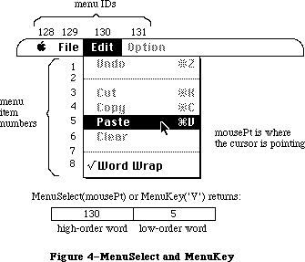 Figure 4–MenuSelect and MenuKey
Assembly-language note: If the global variable MBarEnable is nonzero,
MenuSelect knows that every menu currently in
the menu bar belongs to a desk accessory. (See
the Desk Manager chapter for more information.)
You can store in the global variables MenuHook and
MBarHook the addresses of routines that will be called
during MenuSelect. Both variables are initialized to
0 by InitMenus. The routine whose address is in
MenuHook (if any) will be called repeatedly (with no
parameters) while the mouse button is down. The
routine whose address is in MBarHook (if any) will
be called after the title of the menu is highlighted
and the menu rectangle is calculated, but before the
menu is drawn. (The menu rectangle is the rectangle in
which the menu will be drawn, in global coordinates.)
The routine is passed a pointer to the menu rectangle
on the stack. It should normally return 0 in register
D0; returning 1 will abort MenuSelect.
If the user chooses an item with a submenu, MenuSelect returns zero, meaning that no item was selected. If the user selects an item from a hierarchical menu, the menuID of the hierarchical menu and the menuItem of the item chosen are returned, just as though the item had been in a regular menu.
If MenuSelect returns zero, an application may call MenuChoice to determine whether the mouse was released over either a disabled menu item or an item with a submenu.
Note: The global variable TheMenu contains the ID of the highlighted menu in
the menu bar. If an item from a hierarchical menu is chosen, TheMenu
contains the ID of the “owner” menu, not the ID of the hierarchical menu.
FUNCTION MenuKey (ch: CHAR) : LONGINT;
MenuKey maps the given character to the associated menu and item for that character. When you get a key-down event with the Command key held down—or an auto-key event, if the command being invoked is repeatable—call MenuKey with the character that was typed. MenuKey highlights the appropriate menu title, and returns a long integer containing the menu ID in its high-order word and the menu item number in its low-order word, just as MenuSelect does (see Figure 4 above). After performing the chosen task, your application should call HiliteMenu(0) to remove the highlighting from the menu title.
If the given character isn’t associated with any enabled menu item currently in the menu list, MenuKey returns 0 in the high-order word of the long integer, and the low-order word is undefined.
If the given character invokes a menu item in a menu belonging to a desk accessory, MenuKey (like MenuSelect) passes the menu ID and item number to the Desk Manager procedure SystemMenu for processing, and returns 0 to your application in the high-order word of the result.
Note: There should never be more than one item in the menu list with the
same keyboard equivalent, but if there is, MenuKey returns the first
such item it encounters, scanning the menus from right to left and
their items from top to bottom.
The MenuKey routine first searches for the given key in the regular portion of the MenuList, and if it doesn’t find it there, searches for the key in the hierarchical portion of the MenuList. If the key is in a hierarchical menu, MenuKey highlights the menu title of the menu that “owns” the hierarchical menu. Ownership in this case means the menu in the menu bar that the user would first encounter on the way to the item with the given Command-key equivalent. Because several levels of hierarchy are possible, this traversal may not always be obvious to the user. As before, after performing the chosen task, your application should call HiliteMenu(0) to remove the highlighting from the menu title.
Note: The Command-key codes $1B (Control-[ ) through $1F (Control- _ ) are
reserved by Apple Computer to indicate meanings other than Command-key
equivalents. These key codes are ignored by MenuKey, and a result of
zero is always returned. Applications must never use these codes for
their own use.
The global variable TheMenu contains the ID of the highlighted menu in the menu bar. If an item from a hierarchical menu is chosen, TheMenu contains the ID of the “owner” menu, not the ID of the hierarchical menu.
It’s possible, although undesirable, to define so-called “circular” hierarchical menus. A circular hierarchical menu is one in which a submenu has an “ancestor” that is also one of its “offspring”. If MenuKey detects circular hierarchical menus, a SysError = 86 = #DSHMenuFndErr is generated.
PROCEDURE HiliteMenu (menuID: INTEGER);
HiliteMenu highlights the title of the given menu, or does nothing if the title is already highlighted. Since only one menu title can be highlighted at a time, it unhighlights any previously highlighted menu title. If menuID is 0 (or isn’t the ID of any menu in the menu list), HiliteMenu simply unhighlights whichever menu title is highlighted (if any).
After MenuSelect or MenuKey, your application should perform the chosen task and then call HiliteMenu(0) to unhighlight the chosen menu title.
Assembly-language note: The global variable TheMenu contains the menu ID
of the currently highlighted menu.
Previously, highlighting a menu title meant inverting the title rectangle, and dehighlighting it meant reinverting it, so that it returned to normal. With color titles, color inversion is usually aesthetically unacceptable, so there is a need to draw the highlighted menu title.
HiliteMenu begins by restoring the bits behind the currently highlighted title
(if there is one). It then saves the bits behind the title rectangle, and draws the highlighted title. HiliteMenu(0) dehighlights the currently highlighted menu by restoring the bits behind the title.
Note: Because an application can only save the bits behind the menu title,
only one menu title can be highlighted at a time.
_______________________________________________________________________________
»Controlling the Appearance of Items
PROCEDURE SetItem (theMenu: MenuHandle; item: INTEGER; itemString: Str255);
SetItem changes the text of the given menu item to itemString. It doesn’t recognize the meta-characters used in AppendMenu; if you include them in itemString, they will appear in the text of the menu item. The attributes already in effect for this item—its character style, icon, and so on—remain in effect. ItemString may be blank but should not be the empty string.
Note: It’s good practice to store the text of itemString in a resource
file instead of passing it directly.
Use SetItem to change between the two forms of a toggled command—for example, to change “Show Clipboard” to “Hide Clipboard” when the Clipboard is already showing.
Note: To avoid confusing the user, don’t capriciously change the text
of menu items.
PROCEDURE GetItem (theMenu: MenuHandle; item: INTEGER;
VAR itemString: Str255);
GetItem returns the text of the given menu item in itemString. It doesn’t place any meta-characters in the string. This procedure is useful for getting the name of a menu item that was installed with AddResMenu or InsertResMenu.
PROCEDURE DisableItem (theMenu: MenuHandle; item: INTEGER);
Given a menu item number in the item parameter, DisableItem disables that menu item; given 0 in the item parameter, it disables the entire menu.
Disabled menu items appear dimmed and are not highlighted when the cursor moves over them. MenuSelect and MenuKey return 0 in the high-order word of their result if the user attempts to invoke a disabled item. Use DisableItem to disable all menu choices that aren’t appropriate at a given time (such as a Cut command when there’s no text selection).
All menu items are initially enabled unless you specify otherwise (such as by using the “(” meta- character in a call to AppendMenu).
When you disable an entire menu, call DrawMenuBar to update the menu bar. The title of a disabled menu and every item in it are dimmed.
The EnableItem and DisableItem routines provide enable flags that can handle the title and 31 menu items. All items greater than 31 will be ignored by these calls and will always be enabled.
PROCEDURE EnableItem (theMenu: MenuHandle; item: INTEGER);
Given a menu item number in the item parameter, EnableItem enables the item
(which may have been disabled with the DisableItem procedure, or with the “(” meta-character in the AppendMenu string).
Given 0 in the item parameter, EnableItem enables the menu as a whole, but any items that were disabled separately (before the entire menu was disabled) remain so. When you enable an entire menu, call DrawMenuBar to update the menu bar.
The item or menu title will no longer appear dimmed and can be chosen like any other enabled item or menu.
PROCEDURE CheckItem (theMenu: MenuHandle; item: INTEGER; checked: BOOLEAN);
CheckItem places or removes a check mark at the left of the given menu item. After you call CheckItem with checked=TRUE, a check mark will appear each subsequent time the menu is pulled down. Calling CheckItem with checked=FALSE removes the check mark from the menu item (or, if it’s marked with a different character, removes that mark).
Menu items are initially unmarked unless you specify otherwise (such as with the “!” meta-character in a call to AppendMenu).
PROCEDURE SetItemMark (theMenu: MenuHandle; item: INTEGER; markChar: CHAR);
Assembly-language note: The macro you invoke to call SetItemMark from
assembly language is named _SetItmMark.
SetItemMark marks the given menu item in a more general manner than CheckItem. It allows you to place any character in the system font, not just the check mark, to the left of the item. The character is passed in the markChar parameter.
Note: The Font Manager defines constants for the check mark and other special
characters that can’t normally be typed from the keyboard: the apple
symbol, the Command key symbol, and a diamond symbol. See the Font
Manager chapter for more information.
To remove an item’s mark, you can pass the following predefined constant in the markChar parameter:
CONST noMark = 0;
The SetItemMark procedure allows the application to change the submenu associated with a menu item.
PROCEDURE GetItemMark (theMenu: MenuHandle; item: INTEGER;
VAR markChar: CHAR);
Assembly-language note: The macro you invoke to call GetItemMark from
assembly language is named _GetItmMark.
GetItemMark returns in markChar whatever character the given menu item is marked with, or the predefined constant noMark if no mark is present.
The GetItemMark procedure may be used to determine the ID of the hierarchical menu associated with a menu item.
PROCEDURE SetItemIcon (theMenu: MenuHandle; item: INTEGER; icon: Byte);
Assembly-language note: The macro you invoke to call SetItemIcon from
assembly language is named _SetItmIcon.
SetItemIcon associates the given menu item with an icon. It sets the item’s icon number to the given value (an integer from 1 to 255). The Menu Manager adds 256 to the icon number to get the icon’s resource ID, which it passes to the Resource Manager to get the corresponding icon.
Warning: If you call the Resource Manager directly to read or store
menu icons, be sure to adjust your icon numbers accordingly.
Menu items initially have no icons unless you specify otherwise (such as with the “^” meta-character in a call to AppendMenu).
The SetItemIcon procedure should never be called for font items that are international scripts, unless the intention is to change the script number
(there should never be any need to do this).
PROCEDURE GetItemIcon (theMenu: MenuHandle; item: INTEGER; VAR icon: Byte);
Assembly-language note: The macro you invoke to call GetItemIcon from
assembly language is named _GetItmIcon.
GetItemIcon returns the icon number associated with the given menu item, as an integer from 1 to 255, or 0 if the item has not been associated with an icon. The icon number is 256 less than the icon’s resource ID.
The GetItemIcon procedure may be used to determine the script number of a font item that is the name of an international script.
PROCEDURE SetItemStyle (theMenu: MenuHandle; item: INTEGER; chStyle: Style);
Assembly-language note: The macro you invoke to call SetItemStyle from
assembly language is named _SetItmStyle.
SetItemStyle changes the character style of the given menu item to chStyle. For example:
SetItemStyle(thisMenu,1,[bold,italic]) {bold and italic}
Menu items are initially in the plain character style unless you specify otherwise (such as with the “<” meta-character in a call to AppendMenu).
PROCEDURE GetItemStyle (theMenu: MenuHandle; item: INTEGER;
VAR chStyle: Style);
Assembly-language note: The macro you invoke to call GetItemStyle from
assembly language is named _GetItmStyle.
GetItemStyle returns the character style of the given menu item in chStyle.
There is a possible bug in this routine, depending on the interpretation of the address of the VAR parameter chStyle. GetItemStyle assumes that the address on the stack points to a word with chStyle in the low byte. MPW Pascal passes the byte address of chStyle regardless of whether it’s in the high or low byte of a word. Since there has never been a bug report for this “problem”, it is listed here for information only.
_______________________________________________________________________________
»Miscellaneous Routines
PROCEDURE CalcMenuSize (theMenu: MenuHandle);
You can use CalcMenuSize to recalculate the horizontal and vertical dimensions of a menu whose contents have been changed (and store them in the appropriate fields of the menu record). CalcMenuSize is called internally by the Menu Manager after every routine that changes a menu.
FUNCTION CountMItems (theMenu: MenuHandle) : INTEGER;
CountMItems returns the number of menu items in the given menu.
FUNCTION GetMHandle (menuID: INTEGER) : MenuHandle;
Given the menu ID of a menu currently installed in the menu list, GetMHandle returns a handle to that menu; given any other menu ID, it returns NIL.
The GetMHandle routine looks for the menu in the hierarchical portion of the MenuList first, and if it isn’t found, looks in the regular portion of the MenuList. The routine has no way to determine whether the returned menu is associated with a menu, pop-up, or hierarchical menu. Presumably the application will contain that information.
PROCEDURE FlashMenuBar (menuID: INTEGER);
If menuID is 0 (or isn’t the ID of any menu in the menu list), FlashMenuBar inverts the entire menu bar; otherwise, it inverts the title of the given menu. You can call FlashMenuBar(0) twice to blink the menu bar.
FlashMenuBar(0) still inverts the complete menu bar. Strange colors may result if HiliteMenu, or FlashMenuBar with a nonzero parameter, are called while the menu bar is inverted.
FlashMenuBar has been modified so that only one menu may be highlighted at a time (see HiliteMenu). If no menu is currently highlighted, calling FlashMenuBar with a nonzero parameter highlights that menu. If the highlighted menu is different than the one being “flashed”, the previously highlighted menu is first restored to normal, and the new menu is highlighted.
PROCEDURE SetMenuFlash (count: INTEGER);
Assembly-language note: The macro you invoke to call SetMenuFlash from
assembly language is named _SetMFlash.
When the mouse button is released over an enabled menu item, the item blinks briefly to confirm the choice. Normally, your application shouldn’t be concerned with this blinking; the user sets it with the Control Panel desk accessory. If you’re writing a desk accessory like the Control Panel, though, SetMenuFlash allows you to control the duration of the blinking. The count parameter is the number of times menu items will blink; it’s initially 3 if the user hasn’t changed it. A count of 0 disables blinking. Values greater than 3 can be annoyingly slow.
Note: Items in both standard and nonstandard menus blink when chosen. The
appearance of the blinking for a nonstandard menu depends on the menu
definition procedure, as described in “Defining Your Own Menus”.
Assembly-language note: The current count is stored in the global
variable MenuFlash.
_______________________________________________________________________________
»New Routines
The Menu Manager routines listed in this section are implemented for the Macintosh Plus, Macintosh SE, and Macintosh II where noted.
PROCEDURE InitProcMenu (mbResID: INTEGER);
[Macintosh Plus, Macintosh SE, Macintosh II]
Note: The mbVariant field is contained in the low three bits of the
mbResID. The high order 13 bits are used to load the proper 'MBDF'.
The InitProcMenu routine is called when an application has a custom menu bar defproc, 'MBDF'. InitProcMenu allocates a new MenuList if it hasn’t already been allocated by a previous call to InitMenus, and the mbResID is stored in the mbResID field in the MenuList (note that InitWindows calls InitMenus, so that it can obtain the menu bar height).
The effect of InitProcMenu lasts for the duration of the application only; the next InitMenus call will replace the mbResID field in the MenuList with the default value of zero. This affects applications such as development systems, which use multiple heaps and whose “applications” call InitMenus.
Note: Apple reserves mbResID values $000–$100 for its own use.
PROCEDURE DelMCEntries (MenuID, menuItem: INTEGER); [Macintosh II]
The DelMCEntries routine deletes entries from the menu color information table based on the given menuID and menuItem. If the entry is not found, no entry is removed. If the menuItem is mctAllItems (–98), then all Items for the specified ID are removed.
Applications must, of course, never delete the last entry in the menu color information table.
FUNCTION GetMCInfo: MCTableHandle; [Macintosh II]
The GetMCInfo routine creates a copy of the current menu color information table and returns a handle to the copy. It doesn’t affect the current menu color information table. If the copy fails, a NIL handle is returned.
PROCEDURE SetMCInfo (menuCTbl : MCTableHandle); [Macintosh II]
The SetMCInfo routine copies the given menu color information table to the current menu color information table. It first disposes of the current menu color information table, so your application shouldn’t explicitly dispose the current table. If the copy fails, the global variable MemErr contains the error code, and the procedure doesn’t dispose the current menu color information table. Applications should call the MemError function to determine if this call failed.
You can use this procedure to restore a menu color information table previously saved by GetMCInfo. Be sure to call DrawMenuBar to update the menu bar if a new menu bar color or menu title colors have been specified.
PROCEDURE DispMCInfo (menuCTbl : MCTableHandle); [Macintosh II]
Given a handle to a menu color information table, the DispMCInfo routine disposes of the table. No checking is done to determine whether the handle is valid. While this procedure currently only calls DisposHandle, to ensure compatibility with any updates to the color portion of the menu manager, it’s a good idea to use this call.
FUNCTION GetMCEntry (menuID, menuItem : INTEGER): MCEntryPtr; [Macintosh II]
The GetMCEntry routine finds the entry of the specified menuID and menuItem in the menu color information table, and returns a pointer into the table. If the entry is not found, a NIL pointer is returned.
Note: Entries are not removed from the table. Applications must not remove
entries from the table directly; they should always use the procedure
DelMCEntries to remove entries.
Warning: The menu color information table is relocatable, so the GetMCEntry
return value may not be valid across traps that move or purge memory.
Applications should make a copy of the record in this case.
PROCEDURE SetMCEntries (numEntries: INTEGER; menuCEntries: MCTablePtr);
[Macintosh II]
The SetMCEntries procedure takes a pointer to an array of color information records. The array may be of any size, so it’s necessary to also pass the number of entries in the array.
The ID and Item of each entry in the color information record array are checked to see if the entry already exists in the menu color information table. If it exists, the information in the entry is used to update the entry in the color table. If the entry doesn’t exist in the color information table, the entry is added to the table.
Warning: SetMCEntries makes memory management calls that may move or purge
memory; therefore the array menuCEntries should be nonrelocatable
for the duration of this call.
FUNCTION MenuChoice : LONGINT; [Macintosh II]
The MenuChoice routine is called only after the result from MenuSelect is zero. It determines if the mouse-up event that terminated MenuSelect was in a disabled menu item. When the mouse button is released over a disabled item in an application menu, MenuChoice returns a long integer whose high-order word is the menuID of the menu, and whose low-order word is the menu item number for the disabled item “chosen”. If the item number is zero, then the mouse-up event occurred when the mouse was either in the menu title or completely outside the menu; there is no way to distinguish between the two.
Note: This information is available on the Macintosh Plus and Macintosh SE
by directly querying the long word stored in the global variable
MenuDisable ($B54).
This feature has been added to MenuChoice to make it possible for applications to provide better help facilities. For example, when the Finder calls MenuChoice, and determines that a user has chosen the disabled menu item “Empty Trash” with the Finder, the application could display a message telling the user that it can’t empty the trash because there is nothing currently in the trash.
The new MenuChoice capability is implemented by continual updates of the global variable MenuDisable ($B54) whenever a menu is down. As the mouse moves over each item, MenuDisable is updated to reflect the current menu and item ID. The code that changes the value in MenuDisable resides in the standard menu defproc. The return value is undefined when the menu uses a custom menu defproc, unless the custom defproc also supports this feature.
PROCEDURE GetItemCmd (theMenu: menuHandle; item:INTEGER; VAR cmdChar:Char);
[Macintosh Plus, Macintosh SE, Macintosh II]
The GetItemCmd routine may be used to determine whether a menu item has a submenu attached. For a menu item with a submenu, the returned cmdChar will have the value $1B.
PROCEDURE SetItemCmd (theMenu: menuHandle; item:INTEGER; cmdChar:Char);
[Macintosh Plus, Macintosh SE, Macintosh II]
The SetItemCmd routine allows the application to attach a submenu to a menu by passing the character $1B. You should be careful about arbitrarily adding or removing a submenu from a menu item; see the Macintosh User Interface Guidelines chapter for recommendations. Notice that SetItemMark can be used to change the ID of the submenu that is associated with the menu item.
Note: SetItemCmd must never be used to change the Command-key value of a
menu item that doesn’t have a submenu; users must always be free to
change their Command-key preferences.
FUNCTION PopUpMenuSelect (theMenu:menuHandle;
Top,Left,PopUpItem:INTEGER): LONGINT;
[Macintosh Plus, Macintosh SE, Macintosh II]
The PopUpMenuSelect routine allows an application to create a pop-up menu anywhere on the screen. This menu may be colored like any other menu, and it may have submenus. The return value is the same as that for MenuSelect, where the low word is the menu item selected, and the high word is the menu ID. Unlike MenuSelect, PopUpMenuSelect doesn’t highlight any of the menus in the menu bar, so HiliteMenu(0) doesn’t have to be called after completing the chosen task.
Pop-up menus are typically used for lists of items, for example, fonts. See the Macintosh User Interface Guidelines chapter for a description of how to use pop-up menus in your application. See MenuSelect for information about the return value when the menu chosen is a hierarchical menu.
TheMenu is a handle to the menu that you want “popped up”. The PopUpItem is typically the currently selected item, that is, the last item selected, or the first item if nothing was selected. Doing this allows the user to click on a pop-up menu and release again quickly, without changing the item selection by mistake. The parameters Top and Left define where the top left corner of the PopUpItem is to appear, in global coordinates. Typically, these will be the top left coordinates of the pop-up box, so that the menu item appears on top of the pop-up box. See Figure 5 for an example.
Figure 4–MenuSelect and MenuKey
Assembly-language note: If the global variable MBarEnable is nonzero,
MenuSelect knows that every menu currently in
the menu bar belongs to a desk accessory. (See
the Desk Manager chapter for more information.)
You can store in the global variables MenuHook and
MBarHook the addresses of routines that will be called
during MenuSelect. Both variables are initialized to
0 by InitMenus. The routine whose address is in
MenuHook (if any) will be called repeatedly (with no
parameters) while the mouse button is down. The
routine whose address is in MBarHook (if any) will
be called after the title of the menu is highlighted
and the menu rectangle is calculated, but before the
menu is drawn. (The menu rectangle is the rectangle in
which the menu will be drawn, in global coordinates.)
The routine is passed a pointer to the menu rectangle
on the stack. It should normally return 0 in register
D0; returning 1 will abort MenuSelect.
If the user chooses an item with a submenu, MenuSelect returns zero, meaning that no item was selected. If the user selects an item from a hierarchical menu, the menuID of the hierarchical menu and the menuItem of the item chosen are returned, just as though the item had been in a regular menu.
If MenuSelect returns zero, an application may call MenuChoice to determine whether the mouse was released over either a disabled menu item or an item with a submenu.
Note: The global variable TheMenu contains the ID of the highlighted menu in
the menu bar. If an item from a hierarchical menu is chosen, TheMenu
contains the ID of the “owner” menu, not the ID of the hierarchical menu.
FUNCTION MenuKey (ch: CHAR) : LONGINT;
MenuKey maps the given character to the associated menu and item for that character. When you get a key-down event with the Command key held down—or an auto-key event, if the command being invoked is repeatable—call MenuKey with the character that was typed. MenuKey highlights the appropriate menu title, and returns a long integer containing the menu ID in its high-order word and the menu item number in its low-order word, just as MenuSelect does (see Figure 4 above). After performing the chosen task, your application should call HiliteMenu(0) to remove the highlighting from the menu title.
If the given character isn’t associated with any enabled menu item currently in the menu list, MenuKey returns 0 in the high-order word of the long integer, and the low-order word is undefined.
If the given character invokes a menu item in a menu belonging to a desk accessory, MenuKey (like MenuSelect) passes the menu ID and item number to the Desk Manager procedure SystemMenu for processing, and returns 0 to your application in the high-order word of the result.
Note: There should never be more than one item in the menu list with the
same keyboard equivalent, but if there is, MenuKey returns the first
such item it encounters, scanning the menus from right to left and
their items from top to bottom.
The MenuKey routine first searches for the given key in the regular portion of the MenuList, and if it doesn’t find it there, searches for the key in the hierarchical portion of the MenuList. If the key is in a hierarchical menu, MenuKey highlights the menu title of the menu that “owns” the hierarchical menu. Ownership in this case means the menu in the menu bar that the user would first encounter on the way to the item with the given Command-key equivalent. Because several levels of hierarchy are possible, this traversal may not always be obvious to the user. As before, after performing the chosen task, your application should call HiliteMenu(0) to remove the highlighting from the menu title.
Note: The Command-key codes $1B (Control-[ ) through $1F (Control- _ ) are
reserved by Apple Computer to indicate meanings other than Command-key
equivalents. These key codes are ignored by MenuKey, and a result of
zero is always returned. Applications must never use these codes for
their own use.
The global variable TheMenu contains the ID of the highlighted menu in the menu bar. If an item from a hierarchical menu is chosen, TheMenu contains the ID of the “owner” menu, not the ID of the hierarchical menu.
It’s possible, although undesirable, to define so-called “circular” hierarchical menus. A circular hierarchical menu is one in which a submenu has an “ancestor” that is also one of its “offspring”. If MenuKey detects circular hierarchical menus, a SysError = 86 = #DSHMenuFndErr is generated.
PROCEDURE HiliteMenu (menuID: INTEGER);
HiliteMenu highlights the title of the given menu, or does nothing if the title is already highlighted. Since only one menu title can be highlighted at a time, it unhighlights any previously highlighted menu title. If menuID is 0 (or isn’t the ID of any menu in the menu list), HiliteMenu simply unhighlights whichever menu title is highlighted (if any).
After MenuSelect or MenuKey, your application should perform the chosen task and then call HiliteMenu(0) to unhighlight the chosen menu title.
Assembly-language note: The global variable TheMenu contains the menu ID
of the currently highlighted menu.
Previously, highlighting a menu title meant inverting the title rectangle, and dehighlighting it meant reinverting it, so that it returned to normal. With color titles, color inversion is usually aesthetically unacceptable, so there is a need to draw the highlighted menu title.
HiliteMenu begins by restoring the bits behind the currently highlighted title
(if there is one). It then saves the bits behind the title rectangle, and draws the highlighted title. HiliteMenu(0) dehighlights the currently highlighted menu by restoring the bits behind the title.
Note: Because an application can only save the bits behind the menu title,
only one menu title can be highlighted at a time.
_______________________________________________________________________________
»Controlling the Appearance of Items
PROCEDURE SetItem (theMenu: MenuHandle; item: INTEGER; itemString: Str255);
SetItem changes the text of the given menu item to itemString. It doesn’t recognize the meta-characters used in AppendMenu; if you include them in itemString, they will appear in the text of the menu item. The attributes already in effect for this item—its character style, icon, and so on—remain in effect. ItemString may be blank but should not be the empty string.
Note: It’s good practice to store the text of itemString in a resource
file instead of passing it directly.
Use SetItem to change between the two forms of a toggled command—for example, to change “Show Clipboard” to “Hide Clipboard” when the Clipboard is already showing.
Note: To avoid confusing the user, don’t capriciously change the text
of menu items.
PROCEDURE GetItem (theMenu: MenuHandle; item: INTEGER;
VAR itemString: Str255);
GetItem returns the text of the given menu item in itemString. It doesn’t place any meta-characters in the string. This procedure is useful for getting the name of a menu item that was installed with AddResMenu or InsertResMenu.
PROCEDURE DisableItem (theMenu: MenuHandle; item: INTEGER);
Given a menu item number in the item parameter, DisableItem disables that menu item; given 0 in the item parameter, it disables the entire menu.
Disabled menu items appear dimmed and are not highlighted when the cursor moves over them. MenuSelect and MenuKey return 0 in the high-order word of their result if the user attempts to invoke a disabled item. Use DisableItem to disable all menu choices that aren’t appropriate at a given time (such as a Cut command when there’s no text selection).
All menu items are initially enabled unless you specify otherwise (such as by using the “(” meta- character in a call to AppendMenu).
When you disable an entire menu, call DrawMenuBar to update the menu bar. The title of a disabled menu and every item in it are dimmed.
The EnableItem and DisableItem routines provide enable flags that can handle the title and 31 menu items. All items greater than 31 will be ignored by these calls and will always be enabled.
PROCEDURE EnableItem (theMenu: MenuHandle; item: INTEGER);
Given a menu item number in the item parameter, EnableItem enables the item
(which may have been disabled with the DisableItem procedure, or with the “(” meta-character in the AppendMenu string).
Given 0 in the item parameter, EnableItem enables the menu as a whole, but any items that were disabled separately (before the entire menu was disabled) remain so. When you enable an entire menu, call DrawMenuBar to update the menu bar.
The item or menu title will no longer appear dimmed and can be chosen like any other enabled item or menu.
PROCEDURE CheckItem (theMenu: MenuHandle; item: INTEGER; checked: BOOLEAN);
CheckItem places or removes a check mark at the left of the given menu item. After you call CheckItem with checked=TRUE, a check mark will appear each subsequent time the menu is pulled down. Calling CheckItem with checked=FALSE removes the check mark from the menu item (or, if it’s marked with a different character, removes that mark).
Menu items are initially unmarked unless you specify otherwise (such as with the “!” meta-character in a call to AppendMenu).
PROCEDURE SetItemMark (theMenu: MenuHandle; item: INTEGER; markChar: CHAR);
Assembly-language note: The macro you invoke to call SetItemMark from
assembly language is named _SetItmMark.
SetItemMark marks the given menu item in a more general manner than CheckItem. It allows you to place any character in the system font, not just the check mark, to the left of the item. The character is passed in the markChar parameter.
Note: The Font Manager defines constants for the check mark and other special
characters that can’t normally be typed from the keyboard: the apple
symbol, the Command key symbol, and a diamond symbol. See the Font
Manager chapter for more information.
To remove an item’s mark, you can pass the following predefined constant in the markChar parameter:
CONST noMark = 0;
The SetItemMark procedure allows the application to change the submenu associated with a menu item.
PROCEDURE GetItemMark (theMenu: MenuHandle; item: INTEGER;
VAR markChar: CHAR);
Assembly-language note: The macro you invoke to call GetItemMark from
assembly language is named _GetItmMark.
GetItemMark returns in markChar whatever character the given menu item is marked with, or the predefined constant noMark if no mark is present.
The GetItemMark procedure may be used to determine the ID of the hierarchical menu associated with a menu item.
PROCEDURE SetItemIcon (theMenu: MenuHandle; item: INTEGER; icon: Byte);
Assembly-language note: The macro you invoke to call SetItemIcon from
assembly language is named _SetItmIcon.
SetItemIcon associates the given menu item with an icon. It sets the item’s icon number to the given value (an integer from 1 to 255). The Menu Manager adds 256 to the icon number to get the icon’s resource ID, which it passes to the Resource Manager to get the corresponding icon.
Warning: If you call the Resource Manager directly to read or store
menu icons, be sure to adjust your icon numbers accordingly.
Menu items initially have no icons unless you specify otherwise (such as with the “^” meta-character in a call to AppendMenu).
The SetItemIcon procedure should never be called for font items that are international scripts, unless the intention is to change the script number
(there should never be any need to do this).
PROCEDURE GetItemIcon (theMenu: MenuHandle; item: INTEGER; VAR icon: Byte);
Assembly-language note: The macro you invoke to call GetItemIcon from
assembly language is named _GetItmIcon.
GetItemIcon returns the icon number associated with the given menu item, as an integer from 1 to 255, or 0 if the item has not been associated with an icon. The icon number is 256 less than the icon’s resource ID.
The GetItemIcon procedure may be used to determine the script number of a font item that is the name of an international script.
PROCEDURE SetItemStyle (theMenu: MenuHandle; item: INTEGER; chStyle: Style);
Assembly-language note: The macro you invoke to call SetItemStyle from
assembly language is named _SetItmStyle.
SetItemStyle changes the character style of the given menu item to chStyle. For example:
SetItemStyle(thisMenu,1,[bold,italic]) {bold and italic}
Menu items are initially in the plain character style unless you specify otherwise (such as with the “<” meta-character in a call to AppendMenu).
PROCEDURE GetItemStyle (theMenu: MenuHandle; item: INTEGER;
VAR chStyle: Style);
Assembly-language note: The macro you invoke to call GetItemStyle from
assembly language is named _GetItmStyle.
GetItemStyle returns the character style of the given menu item in chStyle.
There is a possible bug in this routine, depending on the interpretation of the address of the VAR parameter chStyle. GetItemStyle assumes that the address on the stack points to a word with chStyle in the low byte. MPW Pascal passes the byte address of chStyle regardless of whether it’s in the high or low byte of a word. Since there has never been a bug report for this “problem”, it is listed here for information only.
_______________________________________________________________________________
»Miscellaneous Routines
PROCEDURE CalcMenuSize (theMenu: MenuHandle);
You can use CalcMenuSize to recalculate the horizontal and vertical dimensions of a menu whose contents have been changed (and store them in the appropriate fields of the menu record). CalcMenuSize is called internally by the Menu Manager after every routine that changes a menu.
FUNCTION CountMItems (theMenu: MenuHandle) : INTEGER;
CountMItems returns the number of menu items in the given menu.
FUNCTION GetMHandle (menuID: INTEGER) : MenuHandle;
Given the menu ID of a menu currently installed in the menu list, GetMHandle returns a handle to that menu; given any other menu ID, it returns NIL.
The GetMHandle routine looks for the menu in the hierarchical portion of the MenuList first, and if it isn’t found, looks in the regular portion of the MenuList. The routine has no way to determine whether the returned menu is associated with a menu, pop-up, or hierarchical menu. Presumably the application will contain that information.
PROCEDURE FlashMenuBar (menuID: INTEGER);
If menuID is 0 (or isn’t the ID of any menu in the menu list), FlashMenuBar inverts the entire menu bar; otherwise, it inverts the title of the given menu. You can call FlashMenuBar(0) twice to blink the menu bar.
FlashMenuBar(0) still inverts the complete menu bar. Strange colors may result if HiliteMenu, or FlashMenuBar with a nonzero parameter, are called while the menu bar is inverted.
FlashMenuBar has been modified so that only one menu may be highlighted at a time (see HiliteMenu). If no menu is currently highlighted, calling FlashMenuBar with a nonzero parameter highlights that menu. If the highlighted menu is different than the one being “flashed”, the previously highlighted menu is first restored to normal, and the new menu is highlighted.
PROCEDURE SetMenuFlash (count: INTEGER);
Assembly-language note: The macro you invoke to call SetMenuFlash from
assembly language is named _SetMFlash.
When the mouse button is released over an enabled menu item, the item blinks briefly to confirm the choice. Normally, your application shouldn’t be concerned with this blinking; the user sets it with the Control Panel desk accessory. If you’re writing a desk accessory like the Control Panel, though, SetMenuFlash allows you to control the duration of the blinking. The count parameter is the number of times menu items will blink; it’s initially 3 if the user hasn’t changed it. A count of 0 disables blinking. Values greater than 3 can be annoyingly slow.
Note: Items in both standard and nonstandard menus blink when chosen. The
appearance of the blinking for a nonstandard menu depends on the menu
definition procedure, as described in “Defining Your Own Menus”.
Assembly-language note: The current count is stored in the global
variable MenuFlash.
_______________________________________________________________________________
»New Routines
The Menu Manager routines listed in this section are implemented for the Macintosh Plus, Macintosh SE, and Macintosh II where noted.
PROCEDURE InitProcMenu (mbResID: INTEGER);
[Macintosh Plus, Macintosh SE, Macintosh II]
Note: The mbVariant field is contained in the low three bits of the
mbResID. The high order 13 bits are used to load the proper 'MBDF'.
The InitProcMenu routine is called when an application has a custom menu bar defproc, 'MBDF'. InitProcMenu allocates a new MenuList if it hasn’t already been allocated by a previous call to InitMenus, and the mbResID is stored in the mbResID field in the MenuList (note that InitWindows calls InitMenus, so that it can obtain the menu bar height).
The effect of InitProcMenu lasts for the duration of the application only; the next InitMenus call will replace the mbResID field in the MenuList with the default value of zero. This affects applications such as development systems, which use multiple heaps and whose “applications” call InitMenus.
Note: Apple reserves mbResID values $000–$100 for its own use.
PROCEDURE DelMCEntries (MenuID, menuItem: INTEGER); [Macintosh II]
The DelMCEntries routine deletes entries from the menu color information table based on the given menuID and menuItem. If the entry is not found, no entry is removed. If the menuItem is mctAllItems (–98), then all Items for the specified ID are removed.
Applications must, of course, never delete the last entry in the menu color information table.
FUNCTION GetMCInfo: MCTableHandle; [Macintosh II]
The GetMCInfo routine creates a copy of the current menu color information table and returns a handle to the copy. It doesn’t affect the current menu color information table. If the copy fails, a NIL handle is returned.
PROCEDURE SetMCInfo (menuCTbl : MCTableHandle); [Macintosh II]
The SetMCInfo routine copies the given menu color information table to the current menu color information table. It first disposes of the current menu color information table, so your application shouldn’t explicitly dispose the current table. If the copy fails, the global variable MemErr contains the error code, and the procedure doesn’t dispose the current menu color information table. Applications should call the MemError function to determine if this call failed.
You can use this procedure to restore a menu color information table previously saved by GetMCInfo. Be sure to call DrawMenuBar to update the menu bar if a new menu bar color or menu title colors have been specified.
PROCEDURE DispMCInfo (menuCTbl : MCTableHandle); [Macintosh II]
Given a handle to a menu color information table, the DispMCInfo routine disposes of the table. No checking is done to determine whether the handle is valid. While this procedure currently only calls DisposHandle, to ensure compatibility with any updates to the color portion of the menu manager, it’s a good idea to use this call.
FUNCTION GetMCEntry (menuID, menuItem : INTEGER): MCEntryPtr; [Macintosh II]
The GetMCEntry routine finds the entry of the specified menuID and menuItem in the menu color information table, and returns a pointer into the table. If the entry is not found, a NIL pointer is returned.
Note: Entries are not removed from the table. Applications must not remove
entries from the table directly; they should always use the procedure
DelMCEntries to remove entries.
Warning: The menu color information table is relocatable, so the GetMCEntry
return value may not be valid across traps that move or purge memory.
Applications should make a copy of the record in this case.
PROCEDURE SetMCEntries (numEntries: INTEGER; menuCEntries: MCTablePtr);
[Macintosh II]
The SetMCEntries procedure takes a pointer to an array of color information records. The array may be of any size, so it’s necessary to also pass the number of entries in the array.
The ID and Item of each entry in the color information record array are checked to see if the entry already exists in the menu color information table. If it exists, the information in the entry is used to update the entry in the color table. If the entry doesn’t exist in the color information table, the entry is added to the table.
Warning: SetMCEntries makes memory management calls that may move or purge
memory; therefore the array menuCEntries should be nonrelocatable
for the duration of this call.
FUNCTION MenuChoice : LONGINT; [Macintosh II]
The MenuChoice routine is called only after the result from MenuSelect is zero. It determines if the mouse-up event that terminated MenuSelect was in a disabled menu item. When the mouse button is released over a disabled item in an application menu, MenuChoice returns a long integer whose high-order word is the menuID of the menu, and whose low-order word is the menu item number for the disabled item “chosen”. If the item number is zero, then the mouse-up event occurred when the mouse was either in the menu title or completely outside the menu; there is no way to distinguish between the two.
Note: This information is available on the Macintosh Plus and Macintosh SE
by directly querying the long word stored in the global variable
MenuDisable ($B54).
This feature has been added to MenuChoice to make it possible for applications to provide better help facilities. For example, when the Finder calls MenuChoice, and determines that a user has chosen the disabled menu item “Empty Trash” with the Finder, the application could display a message telling the user that it can’t empty the trash because there is nothing currently in the trash.
The new MenuChoice capability is implemented by continual updates of the global variable MenuDisable ($B54) whenever a menu is down. As the mouse moves over each item, MenuDisable is updated to reflect the current menu and item ID. The code that changes the value in MenuDisable resides in the standard menu defproc. The return value is undefined when the menu uses a custom menu defproc, unless the custom defproc also supports this feature.
PROCEDURE GetItemCmd (theMenu: menuHandle; item:INTEGER; VAR cmdChar:Char);
[Macintosh Plus, Macintosh SE, Macintosh II]
The GetItemCmd routine may be used to determine whether a menu item has a submenu attached. For a menu item with a submenu, the returned cmdChar will have the value $1B.
PROCEDURE SetItemCmd (theMenu: menuHandle; item:INTEGER; cmdChar:Char);
[Macintosh Plus, Macintosh SE, Macintosh II]
The SetItemCmd routine allows the application to attach a submenu to a menu by passing the character $1B. You should be careful about arbitrarily adding or removing a submenu from a menu item; see the Macintosh User Interface Guidelines chapter for recommendations. Notice that SetItemMark can be used to change the ID of the submenu that is associated with the menu item.
Note: SetItemCmd must never be used to change the Command-key value of a
menu item that doesn’t have a submenu; users must always be free to
change their Command-key preferences.
FUNCTION PopUpMenuSelect (theMenu:menuHandle;
Top,Left,PopUpItem:INTEGER): LONGINT;
[Macintosh Plus, Macintosh SE, Macintosh II]
The PopUpMenuSelect routine allows an application to create a pop-up menu anywhere on the screen. This menu may be colored like any other menu, and it may have submenus. The return value is the same as that for MenuSelect, where the low word is the menu item selected, and the high word is the menu ID. Unlike MenuSelect, PopUpMenuSelect doesn’t highlight any of the menus in the menu bar, so HiliteMenu(0) doesn’t have to be called after completing the chosen task.
Pop-up menus are typically used for lists of items, for example, fonts. See the Macintosh User Interface Guidelines chapter for a description of how to use pop-up menus in your application. See MenuSelect for information about the return value when the menu chosen is a hierarchical menu.
TheMenu is a handle to the menu that you want “popped up”. The PopUpItem is typically the currently selected item, that is, the last item selected, or the first item if nothing was selected. Doing this allows the user to click on a pop-up menu and release again quickly, without changing the item selection by mistake. The parameters Top and Left define where the top left corner of the PopUpItem is to appear, in global coordinates. Typically, these will be the top left coordinates of the pop-up box, so that the menu item appears on top of the pop-up box. See Figure 5 for an example.
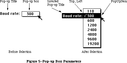 Figure 5–Pop-up Box Parameters
»Drawing the Pop-Up Box
Your application is responsible for drawing the pop-up box. A pop-up box is a rectangle that is the same height as the menu item, is wide enough to show the currently selected item, and has a one-pixel-wide drop shadow.
The pop-up box must be the same height as a menu item so that when the menu appears, the cursor will be in the previously chosen item. If the pop-up box is too tall, the user could click once quickly in a pop-up box and unintentionally choose a different menu item. The height of a menu item in the system font is the ascent + descent + leading.
The pop-up box has a title to its left. The application is responsible for recognizing a mouse-down event in the pop-up box, and highlighting the title to the left of the pop-up menu box before calling MenuSelect. Similarly, the application is responsible for highlighting the title if the pop-up menu has Command-key equivalents.
Before calling PopUpMenuSelect, the pop-up menu must be installed in the hierarchical portion of the MenuList by passing a value of –1 as the “beforeID” to InsertMenu.
The following is a sample psuedocode stub that might be used to track a pop-up menu:
if mouse is in popUpMenuRect then
myInvertPopUpTitle(); {invert title of pop-up menu}
InsertMenu(popupMenuHandle, -1); {-1 means hierarchical menu}
Result = PopUpMenuSelect(popUpMenuHandle, popUpRect.Top,
popUpRect.Left, lastItemSelected);
DeleteMenu(popUpMenuID);
myInvertPopUpTitle(); {return pop-up title to normal}
endif
Notice that PopUpMenuSelect’s sole function is to display the pop-up menu and track the mouse during a mouse-down event. It is the application’s responsibility to handle all other pop-up menu functions, such as drawing the pop-up box, drawing and highlighting the title, and changing the entry in the pop-up box after an item has been chosen from the pop-up menu. This could all be handled by creating a pop-up menu control within the application.
When calling PopUpMenuSelect, the pop-up menu must be in the MenuList for the duration of the call. The code above shows a call the InsertMenu before, and a call to DeleteMenu after, the call to PopUpMenuSelect. The InsertMenu must be used at some time before the call to PopUpMenuSelect, but it’s not necessary to call DeleteMenu immediately afterwards; the pop-up menu may be left in the MenuList if desired.
Pop-up menu items can have Command-key equivalents. The application must provide sufficient visual feedback, normally provided by using MenuKey, by inverting the pop-up title.
_______________________________________________________________________________
»DEFINING YOUR OWN MENUS
_______________________________________________________________________________
The standard type of Macintosh menu is predefined for you. However, you may want to define your own type of menu—one with more graphics, or perhaps a nonlinear text arrangement. QuickDraw and the Menu Manager make it possible for you to do this.
To define your own type of menu, you write a menu definition procedure and store it in a resource file. The Menu Manager calls the menu definition procedure to perform basic operations such as drawing the menu.
A menu in a resource file contains the resource ID of its menu definition procedure. The routine you use to read in the menu is GetMenu (or GetNewMBar, which calls GetMenu). If you store the resource ID of your own menu definition procedure in a menu in a resource file, GetMenu will take care of reading the procedure into memory and storing a handle to it in the menuProc field of the menu record.
If you create your menus with NewMenu instead of storing them as resources, NewMenu stores a handle to the standard menu definition procedure in the menu record’s menuProc field. You must replace this with a handle to your own menu definition procedure, and then call CalcMenuSize. If your menu definition procedure is in a resource file, you get the handle by calling the Resource Manager to read it from the resource file into memory.
_______________________________________________________________________________
»The Menu Definition Procedure
The menu definition procedure is usually written in assembly language, but may be written in any high-level language.
Assembly-language note: The procedure’s entry point must be at the beginning.
You may choose any name you wish for the menu definition procedure. Here’s how you would declare one named MyMenu:
PROCEDURE MyMenu (message: INTEGER; theMenu: MenuHandle; VAR menuRect: Rect;
hitPt: Point; VAR whichItem: INTEGER);
The message parameter identifies the operation to be performed. It has one of the following values:
CONST mDrawMsg = 0; {draw the menu}
mChooseMsg = 1; {tell which item was chosen and highlight it}
mSizeMsg = 2; {calculate the menu's dimensions}
The parameter theMenu indicates the menu that the operation will affect. MenuRect is the rectangle (in global coordinates) in which the menu is located; it’s used when the message is mDrawMsg or mChooseMsg.
Note: MenuRect is declared as a VAR parameter not because its value is
changed, but because of a Pascal feature that will cause an error
when that parameter isn’t used.
The message mDrawMsg tells the menu definition procedure to draw the menu inside menuRect. The current grafPort will be the Window Manager port. (For details on drawing, see the QuickDraw chapter.) The standard menu definition procedure figures out how to draw the menu items by looking in the menu record at the data that defines them; this data is described in detail under “Formats of Resources for Menus” below. For menus of your own definition, you may set up the data defining the menu items any way you like, or even omit it altogether
(in which case all the information necessary to draw the menu would be in the menu definition procedure itself). You should also check the enableFlags field of the menu record to see whether the menu is disabled (or whether any of the menu items are disabled, if you’re using all the flags), and if so, draw it in gray.
Note: MenuKey will always search the menuData field of a MenuInfo record for
Command-key equivalents until it finds a zero where a standard menu
title should be, even if the MenuInfo record is for one of your own
'MDEF' resources. To prevent MenuKey from finding a Command-key
equivalent in your MenuInfo record, put a couple of bytes of zeros
just after the menu’s title.
Warning: Don’t change the font from the system font for menu text.
(The Window Manager port uses the system font.)
When the menu definition procedure receives the message mChooseMsg, the hitPt parameter is the mouse location (in global coordinates), and the whichItem parameter is the item number of the last item that was chosen from this menu
(whichItem is initially set to 0). The procedure should determine whether the mouse location is in an enabled menu item, by checking whether hitPt is inside menuRect, whether the menu is enabled, and whether hitPt is in an enabled menu item:
• If the mouse location is in an enabled menu item, unhighlight whichItem
and highlight the new item (unless the new item is the same as the
whichItem), and return the item number of the new item in whichItem.
• If the mouse location isn’t in an enabled item, unhighlight whichItem
and return 0.
Note: When the Menu Manager needs to make a chosen menu item blink, it
repeatedly calls the menu definition procedure with the message
mChooseMsg, causing the item to be alternately highlighted and
unhighlighted.
Finally, the message mSizeMsg tells the menu definition procedure to calculate the horizontal and vertical dimensions of the menu and store them in the menuWidth and menuHeight fields of the menu record.
The following section describes changes to the default menu definition procedure ('MDEF' resource 0); some of the information presented in this section is accessible only through assembly language.
Note: These features will work with the 64K ROM if the new menu definition
procedure is in the system resource file.
»Variable Size Fonts
Menus are displayed in the system font. Since the system font and font size can now be changed, the menu definition procedure calls the QuickDraw procedure GetFontInfo for the system font to determine the height of menu items
»Scrolling Menus
The default menu definition procedure allows longer menus by implementing automatic scrolling. If the entire menu cannot be drawn on screen, dragging the cursor below the last displayed item will cause the items in the menu to scroll up. Similarly, if items have been scrolled past the top of the menu, dragging the cursor into the highlighted portion of the menu bar will cause the menu to scroll back down. The maximum number of items that can be drawn on the standard Macintosh screen with this new menu definition function is 19 (instead of 20).
Warning: You should not disable any menu items in a menu containing more than
31 items because the enableFlags field of the MenuInfoRec can only
handle 31 items.
_______________________________________________________________________________
»THE STANDARD MENU DEFINITION PROCEDURE
_______________________________________________________________________________
This section describes changes made to the default menu definition procedure
'MDEF' resource = 0, for all Macintoshes except the 64K and 512K versions. The 'MDEF' resource has been modified to ignore all undefined messages. Any custom
'MDEF' should do the same. This allows Apple to define new messages (as described below for pop-up menus) without impacting custom 'MDEF' resources. Apple recognizes that applications may want to call their custom defprocs for information, and has reserved all messages above and including 128 for application use. Apple’s defprocs will ignore all messages above and including 128.
For the latest standard 'MDEF', the version number = 10. Version 10 and all later versions include the features listed below.
For hierarchical menus:
• The triangular marker indicating that an item has a submenu appears
in the location where the Command-key equivalent is normally shown.
• The Command-key values $1B (Control-[ ) through $1F (Control-_ ) are
reserved by Apple to have meanings other than command keys.
For scrolling menus:
• When a menu is scrollable, scrolling indicators appear. If the menu
scrolls up, a triangular indicator appears in place of the last item
in the list, and if the menu scrolls down, an indicator appears in place
of the first item in the list. The menu scrolls when the cursor is moved
into the area of the indicator, or is directly above or below the menu.
For pop-up menus:
• A new message has been added to the standard 'MDEF' resource. Message #3,
pop-up menu placement, asks the defproc to calculate the menu rectangle
of the pop-up menu.
Parameter On Entry Return Value
message 3
theMenu menuHandle
menuRect Pop-up menu’s rectangle
hitPt Top left of PopupItem
whichItem PopupItem Top of menu if menu scrolls
When a pop-up menu appears, the menu is adjusted on the screen so that
the previously selected item appears on top of the pop-up menu box. The
previously selected item is passed in the parameter whichItem, and the
top left corner of the pop-up menu box is passed in hitPt. On exit, the
rectangle in which the pop-up menu is to appear is returned in menuRect.
If the menu is so large that it scrolls, then the actual top of the menu
is returned in whichItem.
X-Ref: Technical Note #172
• When a defproc draws a pop-up menu, its scrolling information must be
placed in the global variables TopMenuItem and AtMenuBottom.
For color menus (Macintosh II only):
• When menu items are drawn, the background of the menu has already been
erased to the color specified for that menu in the menu color information
table, or to white if none is specified. When the mark, item, and
Command-key equivalent fields are drawn, the menu defproc checks the menu
color information table for the colors to use. If there is an item entry,
those colors are used. If there is no item entry, then the default from
the title entry is used. If there is no title entry, then the default from
the menu bar entry is used. If there is no menu bar entry, then black on
white is used.
• When an item is chosen, the background color and the item color are
reversed, and the item is redrawn in those colors. When an item is chosen,
the background color and item color are reset, and the item is redrawn in
those colors.
• If your application uses the standard menu bar defproc to draw menu items
into menus after saving the bits behind and drawing the drop shadow, it
must erase the menu’s background to the correct color. If this isn’t done
when the user has set default menu colors, incorrect colors and unreadable
items can result.
• Custom menu defprocs that use color items must provide the menu background
color. When the standard 'MBDF' clears the menu background and draws the
drop shadow, it clears the menu background to whatever color is specified
in the menu color information table. Custom menu defprocs should either
(1) support color items by accessing the menu color information table or
(2) erase the background of the menu to white before drawing color items.
All menus:
• The menu defproc sets the global variable MenuDisable ($B54) each time a
new item is highlighted. After MenuSelect returns a zero, your application
can query MenuDisable directly, or use MenuChoice, to determine which menu
ID and menu item were chosen.
• The value returned by MenuChoice will be undefined if the last menu
displayed has a custom 'MDEF'. When including a custom 'MDEF' in your
application, you should consider supporting MenuChoice so that desk
accessories providing on-line help for the application will be able to
support all its menus.
• Any application that uses the standard 'MDEF' to draw menu items must set
the global variable TopMenuItem ($A0A). This variable is used by the
standard 'MDEF' to determine if scrolling is necessary. If TopMenuItem
isn’t set properly, scrolling might occur when it shouldn’t. TopMenuItem
should contain global coordinates indicating where the first item in the
menu is to be drawn; typically this is the same as the top of the menu
rectangle. However, your application can use other coordinates if you
don’t want the first menu item to appear at the top of the menu rectangle.
_______________________________________________________________________________
»THE STANDARD MENU BAR DEFINITION PROCEDURE
_______________________________________________________________________________
To give application writers more control over custom menus, a default menu bar definition procedure has been added. This section describes the default menu bar definition procedure ('MBDF' resource = 0). On the Macintosh II, the menu bar defproc provides support for color, pop-up, and hierarchical menus, as well as standard menus. This new defproc supplements the existing standard 'MDEF' resource.
All menu drawing-related activities, previously included in the routines DrawMenuBar, MenuSelect, MenuKey, HiliteMenu, and FlashMenuBar, have been removed from the menu manager code, and placed in the menu bar defproc. Using the menu bar defproc with the menu defproc gives the application writer complete control over the appearance and use of menus.
An application that specifies its own menu bar defproc should call InitProcMenu instead of InitMenus, which then loads the appropriate 'MBDF' resource.
There are currently 13 messages defined for the menu bar defproc:
Msg # Msg Description
0 Draw Draws the menu bar or clears the menu bar.
1 Hit Tests to see if the mouse is in the menu bar
or any currently displayed menus.
2 Calc Calculates the left edges of each menu title in
the MennuList data structure.
3 Init Initializes any menu bar defproc data structures.
4 Dispos Disposes of any menu bar defproc data structures.
5 Hilite Highlights the specified menu title, or inverts
the whole menu bar.
6 Height Returns the menu bar height.
7 Save Saves the bits behind a menu and draws the menu structure.
8 Restor Restores the bits behind a menu.
9 Rect Calculates the rectangle of a menu.
10 SaveAlt Saves more information about a menu after it has been drawn.
11 ResetAlt Resets information about a menu.
12 MenuRgn Returns a region for the menu bar.
Custom 'MBDF' defprocs should ignore messages that are not currently defined in this documentation. Messages numbered 128 and above are reserved for custom defprocs.
You may choose any name you wish for the menu bar defproc. The following example declares a menu bar defproc named MyMenuBar:
FUNCTION MyMenuBar ( selector: INTEGER; message: INTEGER;
parameter1: INTEGER:
parameter2: LONGINT): LONGINT;
_______________________________________________________________________________
»Parameters for Menu Bar Defproc Messages
This section lists the parameters for each message. Note that the menu bar defproc draws directly into the window manager port, or color window manager port if there is one. Any time the menu bar defproc draws in the Window Manager port (or color port) it clips the port to full open before it returns. Full open is defined to be the portRect of the Window Manager, or the color Window Manager port. The exception to this rule is that the Draw message leaves the Window Manager port (or color port) clipped to the menu bar when parameter2 = –1. See the individual message descriptions for more information.
Message #0: Draw:
Called By Selector Parameter1 Parameter2 Result
Window Manager mbVariant none –1 = clear bar none
DrawMenuBar 0 = draw bar
When parameter2 = 0 (zero), the menu bar is cleared to the proper color, the titles are drawn, and the window manager port clip region is set to full open. After all of the titles are drawn, if one of the titles is currently selected
(its menuID is contained in the global variable TheMenu ($A26)), then the title is highlighted. DrawMenuBar passes parameter2 = 0.
When parameter2 = –1 the menu bar is cleared to the proper color, no titles are drawn, and the Window Manger port clip region is set to the menu bar. The Window Manager passes parameter2 = –1.
Message #1: Hit
Called By Selector Parameter1 Parameter2 Result
FindWindow mbVariant none mouse pt 0 = in bar,
no title hit
MenuSelect –1 = not in bar
<pos> =
six-byte offset
The mouse point to be tested for its location is passed in parameter2. First this message checks to see whether the mouse point is in the menu bar. If it is in the menu bar, then the message further checks whether the mouse is in any menu title. If the mouse is in the menu bar but not in a title, the result is 0. If the mouse is in a title, the result is the offset of the title in the menuList. The notation <pos> refers to a result which is a positive value
(greater than zero). A six-byte offset refers to the offset of a menu in the menuList data structure.
If the mouse is not in the menu bar, this message tests whether mouse point is in any currently visible menu. If more than one menu is visible—that is, one or more hierarchical menus are visible—the message searches through those menus backwards, checking the topmost hierarchical menu first. If the mouse point is found to be in a currently visible menu, the result is the six-byte offset of that menu in the menuList.
Message #2: Calc
Called By Selector Parameter1 Parameter2 Result
InsertMenu mbVariant none 0 = all none
DeleteMenu <pos> = six-byte
offset
This message calculates the lastRight and menuLeft fields in the menuList. If parameter2 = 0 then the calculation is done for all of the menus. If parameter2 = the offset of a title in the menuList, then the calculation begins with that menu and continues for all following menus. A six-byte offset refers to the offset of a menu in the menuList data structure. The notation <pos> refers to a result which is a positive value (greater than zero).
Message #3: Init
Called By Selector Parameter1 Parameter2 Result
InitMenus mbVariant none none none
InitProcMenu
This message creates a data structure in the system heap the first time it is called after system startup. It clears the field lastMBSave in that data structure at every call thereafter.
This message is called by InitProcMenu if the MenuList data structure hasn’t been allocated. Applications that switch menu defprocs on the fly, and call InitProcMenu to do so, will need to call the 'MBDF' with the “Init” message to execute this message.
Message #4: Dispose
Called By Selector Parameter1 Parameter2 Result
— mbVariant none none none
Currently, this message does nothing.
Message #5: Hilite
Called By Selector Parameter1 Parameter2 Result
MenuSelect mbVariant none <packed> none
HiliteMenu
FlashMenuBar
Parameter2 contains a packed value: the high word contains the highlight state desired, and the low word contains the menu to be highlighted, which is its six-byte offset in the menuList. The <packed> notation refers to the following: high word 0 = normal, high word 1 = selected, low word 0 = flipbar. A highlight state of 1 (one) means the title is to be selected, and a highlight state of 0
(zero) means that the title is to be returned to normal.
When a menu is selected, the bits behind the title are saved. Next, the color of the title and the color of the menu bar are reversed, and the title is redrawn in these reversed colors. Reversing the colors simply means setting the background color to the title color and the foreground color to the menu bar color. This is necessary because merely inverting the title rectangle with a call to InvertRect, as was done on previous machines, often produces unpleasing and/or unreadable results.
When a menu is deselected—that is, the highlight state is 0 (zero)—the bits behind the title are restored. If there was not enough memory to save the bits behind the title, DrawMenuBar is called to redraw the whole menu bar.
If the low word of parameter2 is zero, the whole menu bar is inverted. FlashMenuBar uses this feature.
Message #6: Height
Called By Selector Parameter1 Parameter2 Result
Window Manager mbVariant none none none
This calculates the menu bar height by looking at the size of the system font, and stores that value in the global variable MBarHeight ($BAA). Note that the Window Manager assumes that the menu bar is at the top of the screen.
Message #7: Save
Called By Selector Parameter1 Parameter2 Result
MenuSelect mbVariant six-byte offset menuRect none
PopUpMenuSelect
Parameter2 is the rectangle into which the menu is to be drawn. Parameter1 is the offset into the menuList of the menu to be drawn. A six-byte offset refers to the offset of the menu into the menuList data structure. First the bits behind the menu are saved. Next the menu rectangle is erased to the proper background color, and the menu structure (i.e., shadow) is drawn. Finally, various information about the menu is stored in the menu bar defproc’s data structure.
Message #8: Restore
Called By Selector Parameter1 Parameter2 Result
MenuSelect mbVariant none none none
PopUpMenuSelect
No parameters are passed; the assumption is that the last displayed menu will always be the first one restored. If there was not enough memory to save the bits behind the menu, an update event is generated for the menu rectangle.
Message #9: GetRect
Called By Selector Parameter1 Parameter2 Result
MenuSelect mbVariant none <packed2> menuRect
PopUpMenuSelect
Parameter2 contains the offset into the menuList data structure for the menu whose rectangle is to be calculated, as well as information about whether this is for a regular menu or a hierarchical menu. The <packed2> notation refers to the following: high word 0 = regular menu, high word nonzero = mouse
pt/hierarchical menu, low-word = six-byte offset of a menu in the MenuList. If the menu is currently showing on the screen, then its rectangle need not be recalculated, since it is stored in the menu bar defproc’s data structure.
If the menu is not currently showing on the screen, the rectangle is calculated. If it is the first menu up, the menu drops from the menu bar. If it is a hierarchical menu, an attempt is made to line up the top of the hierarchical menu with the item that is the “parent” of this submenu.
Message #10: SaveAlt
Called By Selector Parameter1 Parameter2 Result
MenuSelect mbVariant none six-byte offset none
PopUpMenuSelect
This message is called after message #7 (Save) has been executed and the menu defproc has been called to draw the menu items. It currently saves data about the menu’s scrolling position. A six-byte offset refers to the offset of the menu into the menuList data structure.
Message #11: ResetAlt
Called By Selector Parameter1 Parameter2 Result
MenuSelect mbVariant none six-byte offset none
PopUpMenuSelect
This message is currently used to restore the global variables TopMenuItem
($A0A) and AtMenuBottom ($A0C) for the menu where the mouse is currently located. When a hierarchical menu is drawn, its scrolling information will be in the global variables TopMenu Item and AtMenuBottom. For menu scrolling to work properly, the scrolling information for the menu where the mouse is currently located must be in those global variables. A six-byte offset refers to the offset of menu into the menuList data structure.
Message #12: MenuRgn
Called By Selector Parameter1 Parameter2 Result
— mbVariant none region handle region handle
A handle to an empty region is passed in parameter2. The same handle is returned as the result, and the region is the menu bar’s region.
_______________________________________________________________________________
»FORMATS OF RESOURCES FOR MENUS
_______________________________________________________________________________
The resource type for a menu definition procedure is 'MDEF'. The resource data is simply the compiled or assembled code of the procedure.
Icons in menus must be stored in a resource file under the resource type 'ICON' with resource IDs from 257 to 511. Strings in resource files have the resource type 'STR'; if you use the SetItem procedure to change a menu item’s text, you should store the alternate text as a string resource.
The formats of menus and menu bars in resource files are given below.
_______________________________________________________________________________
»Menus in a Resource File
The resource type for a menu is 'MENU'. The resource data for a menu has the format shown below. Once read into memory, this data is stored in a menu record (described earlier in the “Menu Records” section).
Number of bytes Contents
2 bytes Menu ID
2 bytes 0; placeholder for menu width
2 bytes 0; placeholder for menu height
2 bytes Resource ID of menu definition procedure
2 bytes 0 (see comment below)
4 bytes Same as enableFlags field of menu record
1 byte Length of following title in bytes
n bytes Characters of menu title
For each menu item:
1 byte Length of following text in bytes
m bytes Text of menu item
1 byte Icon number, or 0 if no icon
1 byte Keyboard equivalent, or 0 if none
1 byte Character marking menu item, or 0 if none
1 byte Character style of item’s text
1 byte 0, indicating end of menu items
The four bytes beginning with the resource ID of the menu definition procedure serve as a placeholder for the handle to the procedure: When GetMenu is called to read the menu from the resource file, it also reads in the menu definition procedure if necessary, and replaces these four bytes with a handle to the procedure. The resource ID of the standard menu definition procedure is
CONST textMenuProc = 0;
The resource data for a nonstandard menu can define menu items in any way whatsoever, or not at all, depending on the requirements of its menu definition procedure. If the appearance of the items is basically the same as the standard, the resource data might be as shown above, but in fact everything following
“For each menu item” can have any desired format or can be omitted altogether. Similarly, bits 1 to 31 of the enableFlags field may be set and used in any way desired by the menu definition procedure; bit 0 applies to the entire menu and must reflect whether it’s enabled or disabled.
If your menu definition procedure does use the enableFlags field, menus of that type may contain no more than 31 items (1 per available bit); otherwise, the number of items they may contain is limited only by the amount of room on the screen.
Note: See the QuickDraw chapter for the exact format of the
character style byte.
_______________________________________________________________________________
»Menu Bars in a Resource File
The resource type for the contents of a menu bar is 'MBAR' and the resource data has the following format:
Number of bytes Contents
2 bytes Number of menus
For each menu:
2 bytes Resource ID of menu
_______________________________________________________________________________
»SUMMARY OF THE MENU MANAGER
_______________________________________________________________________________
Constants
CONST
hMenuCmd = $1B; {itemCmd == $1B ==> hierarchical menu }
{ attached to this item}
hierMenu = –1; {for use as "beforeID" with InsertMenu}
hPopUpMsg = 3; {pop-up menu placement, asks the defproc to }
{ calculate the menu rectangle of the pop-up menu}
mctAllItems = –98; {for use as a "menuItem" with DelMCEntries}
mctLastIDIndic = -99; {last color table entry has this in ID field}
dsMBarNFnd = 85; {SysErr code indicating MBDF not found. Used }
{ by InitProcMenu and InitMenu}
dsHMenuFindErr = 86; {SysErr code indicating recursive }
{ hierarchical menus defined. Used by MenuKey.}
{ Value indicating item has no mark }
noMark = 0;
{ Messages to menu definition procedure }
mDrawMsg = 0; {draw the menu}
mChooseMsg = 1; {tell which item was chosen and highlight it}
mSizeMsg = 2; {calculate the menu's dimensions}
{ Resource ID of standard menu definition procedure }
textMenuProc = 0;
_______________________________________________________________________________
Data Types
TYPE
MenuHandle = ^MenuPtr;
MenuPtr = ^MenuInfo;
MenuInfo = RECORD
menuID: INTEGER; {menu ID}
menuWidth: INTEGER; {menu width in pixels}
menuHeight: INTEGER; {menu height in pixels}
menuProc: Handle; {menu definition procedure}
enableFlags: LONGINT; {tells if menu or items are enabled}
menuData: Str255 {menu title (and other data)}
END;
MCEntryPtr = ^MCEntry;
MCEntry = RECORD
mctID: INTEGER; {menu ID. ID = 0 is }
{ the menu bar}
mctItem: INTEGER; {menu entry. Item = 0 }
{ is a title}
mctRGB1: RGBColor; {usage depends on ID and Item}
mctRGB2: RGBColor; {usage depends on ID and Item}
mctRGB3: RGBColor; {usage depends on ID and Item}
mctRGB4: RGBColor; {usage depends on ID and Item}
mctReserved: INTEGER; {reserved for internal use}
END;
MCTable = ARRAY [0..0] of MCEntry; {The menu entries are }
{ represented in this array}
MCTablePtr = ^MCTable;
MCTableHandle = ^MCTablePtr;
_______________________________________________________________________________
Routines
Initialization and Allocation
PROCEDURE InitMenus;
FUNCTION NewMenu (menuID: INTEGER; menuTitle: Str255) : MenuHandle;
FUNCTION GetMenu (resourceID: INTEGER) : MenuHandle;
PROCEDURE DisposeMenu (theMenu: MenuHandle);
Forming the Menus
PROCEDURE AppendMenu (theMenu: MenuHandle; data: Str255);
PROCEDURE AddResMenu (theMenu: MenuHandle; theType: ResType);
PROCEDURE InsertResMenu (theMenu: MenuHandle; theType: ResType;
afterItem: INTEGER);
PROCEDURE InsMenuItem (theMenu: MenuHandle; itemString: Str255;
afterItem: INTEGER);
PROCEDURE DelMenuItem (menuItemID: INTEGER);
Forming the Menu Bar
PROCEDURE InsertMenu (theMenu: MenuHandle; beforeID: INTEGER);
PROCEDURE DrawMenuBar;
PROCEDURE DeleteMenu (menuID: INTEGER);
PROCEDURE ClearMenuBar;
FUNCTION GetNewMBar (menuBarID: INTEGER) : Handle;
FUNCTION GetMenuBar : Handle;
PROCEDURE SetMenuBar (menuList: Handle);
Choosing From a Menu
FUNCTION MenuSelect (startPt: Point) : LONGINT;
FUNCTION MenuKey (ch: CHAR) : LONGINT;
PROCEDURE HiliteMenu (menuID: INTEGER);
Controlling the Appearance of Items
PROCEDURE SetItem (theMenu: MenuHandle; item: INTEGER;
itemString: Str255);
PROCEDURE GetItem (theMenu: MenuHandle; item: INTEGER;
VAR itemString: Str255);
PROCEDURE DisableItem (theMenu: MenuHandle; item: INTEGER);
PROCEDURE EnableItem (theMenu: MenuHandle; item: INTEGER);
PROCEDURE CheckItem (theMenu: MenuHandle; item: INTEGER;
checked: BOOLEAN);
PROCEDURE SetItemMark (theMenu: MenuHandle; item: INTEGER; markChar: CHAR);
PROCEDURE GetItemMark (theMenu: MenuHandle; item: INTEGER;
VAR markChar: CHAR);
PROCEDURE SetItemIcon (theMenu: MenuHandle; item: INTEGER; icon: Byte);
PROCEDURE GetItemIcon (theMenu: MenuHandle; item: INTEGER; VAR icon: Byte);
PROCEDURE SetItemStyle (theMenu: MenuHandle; item: INTEGER; chStyle: Style);
PROCEDURE GetItemStyle (theMenu: MenuHandle; item: INTEGER;
VAR chStyle: Style);
Miscellaneous Routines
PROCEDURE CalcMenuSize (theMenu: MenuHandle);
FUNCTION CountMItems (theMenu: MenuHandle) : INTEGER;
FUNCTION GetMHandle (menuID: INTEGER) : MenuHandle;
PROCEDURE FlashMenuBar (menuID: INTEGER);
PROCEDURE SetMenuFlash (count: INTEGER);
New Routines
PROCEDURE InitProcMenu (mbResID: INTEGER);
PROCEDURE DelMCEntries (menuID, menuItem: INTEGER);
FUNCTION GetMCInfo: MCTableHandle;
PROCEDURE SetMCInfo (menuCTbl: MCTableHandle);
PROCEDURE DispMCInfo (menuCTbl: MCTableHandle);
FUNCTION GetMCEntry (menuID, menuItem: INTEGER): MCEntryPtr;
FUNCTION MenuChoice: LONGINT;
PROCEDURE SetMCEntries (numEntries: INTEGER; menuCEntries: MCTablePtr);
PROCEDURE GetItemCmd (theMenu:MenuHandle; item:INTEGER; VAR cmdChar: CHAR);
PROCEDURE SetItemCmd (theMenu:MenuHandle; item:INTEGER; cmdChar: CHAR);
FUNCTION PopUpMenuSelect (theMenu: MenuHandle;
Top, Left, PopupItem: INTEGER;) LONGINT;
_______________________________________________________________________________
Meta-Characters for AppendMenu
Meta-character Usage
; or Return Separates multiple items
^ Followed by an icon number, adds that icon to the item
! Followed by a character, marks the item with that character
< Followed by B, I, U, O, or S, sets the character style
of the item
/ Followed by a character, associates a keyboard equivalent
with the item
( Disables the item
_______________________________________________________________________________
Menu Definition Procedure
PROCEDURE MyMenu (message: INTEGER; theMenu: MenuHandle; VAR menuRect: Rect;
hitPt: Point; VAR whichItem: INTEGER);
_______________________________________________________________________________
Variables
MBarHeight Contains menu bar height derived from the size of the system font.
MenuCInfo Contains handle to the menu color information table.
MenuDisable Contains the menu ID for last menu item chosen, whether or
not it’s disabled.
TheMenu Contains the ID of the highlighted menu in the menu bar.
TopMenuItem Contains information on top menu item for menu scrolling.
AtMenuBottom Contains information on bottom menu item for menu scrolling.
_______________________________________________________________________________
Assembly-Language Information
Constants
; Value indicating item has no mark
noMark .EQU 0
; Messages to menu definition procedure
mDrawMsg .EQU 0 ;draw the menu
mChooseMsg .EQU 1 ;tell which item was chosen and highlight it
mSizeMsg .EQU 2 ;calculate the menu's dimensions
; Resource ID of standard menu definition procedure
textMenuProc .EQU 0
Menu Record Data Structure
menuID Menu ID (word)
menuWidth Menu width in pixels (word)
menuHeight Menu height in pixels (word)
menuDefHandle Handle to menu definition procedure
menuEnable Enable flags (long)
menuData Menu title (preceded by length byte) followed by
data defining the items
menuBlkSize Size in bytes of menu record except menuData field
Menu Color Information Table Structure
mctID EQU $0
mctItem EQU $2
mctRGB1 EQU $4
mctRGB2 EQU $A
mctRGB3 EQU $10
mctRGB4 EQU $16
mctReserved EQU $1C
mctEntrySize EQU $1E
Miscellaneous equates for hierarchical menus
HMenuCmd EQU $1B ;itemCmd == $1B ==> hierarchical menu for this item
ScriptMenuCmd EQU $1C ;itemCmd == $1C ==> item to be displayed in
; script font
AltMenuCmd1 EQU $1D ;itemCmd == $1D ==> unused indicator
; reserved for future Apple use
AltMenuCmd2 EQU $1E ;itemCmd == $1E ==> unused indicator
; reserved for future Apple use
AltMenuCmd3 EQU $1F ;itemCmd == $1F ==> unused indicator
; reserved for future Apple use
hierMenu EQU -1 ;InsertMenu(handle, hierMenu), when
; beforeID ==hierMenu, the handle is
; inserted in the hierarchical menuList
hPopUpMsg EQU 3 ;pop-up menu placement, asks the defproc to
; calculate the menu rectangle of the pop-up menu
Color table search messages
mctAllItems EQU -98 ;search for all items for the given ID
mctLastIDIndic EQU -99 ;last entry in color table has this in ID field
Special Macro Names
Pascal name Macro name
DisposeMenu _DisposMenu
GetItemIcon _GetItmIcon
GetItemMark _GetItmMark
GetItemStyle _GetItmStyle
GetMenu _GetRMenu
SetItemIcon _SetItmIcon
SetItemMark _SetItmMark
SetItemStyle _SetItmStyle
SetMenuFlash _SetMFlash
Variables
MenuList Handle to current menu list
MBarEnable Nonzero if menu bar belongs to a desk accessory (word)
MenuHook Address of routine called repeatedly during MenuSelect
MBarHook Address of routine called by MenuSelect before
menu is drawn (see below)
TheMenu Menu ID of currently highlighted menu (word)
MenuFlash Count for duration of menu item blinking (word)
MBarHook routine
On entry stack: pointer to menu rectangle
On exit D0: 0 to continue MenuSelect
1 to abort MenuSelect
MBarHeight EQU $BAA ;contains menu bar height derived from the
; size of the system font
MenuCInfo EQU $0D50 ;handle to menu color information table
MenuDisable EQU $0B54 ;contains the menu ID for last menu item
; chosen, whether or not it's disabled
TheMenu EQU $A26 ;contains the ID of the highlighted menu
; in the menu bar
TopMenuItem EQU $A0A ;pixel value of top of scrollable menu
AtMenuBottom EQU $A0C ;pixel value of bottom of scrollable menu
Further Reference:
_______________________________________________________________________________
Resource Manager
QuickDraw
Toolbox Event Manager
Font Manager
Window Manager
Technical Note #172, Parameters for MDEF Message #3
Technical Note #222, Custom Menu Flashing Bug
Figure 5–Pop-up Box Parameters
»Drawing the Pop-Up Box
Your application is responsible for drawing the pop-up box. A pop-up box is a rectangle that is the same height as the menu item, is wide enough to show the currently selected item, and has a one-pixel-wide drop shadow.
The pop-up box must be the same height as a menu item so that when the menu appears, the cursor will be in the previously chosen item. If the pop-up box is too tall, the user could click once quickly in a pop-up box and unintentionally choose a different menu item. The height of a menu item in the system font is the ascent + descent + leading.
The pop-up box has a title to its left. The application is responsible for recognizing a mouse-down event in the pop-up box, and highlighting the title to the left of the pop-up menu box before calling MenuSelect. Similarly, the application is responsible for highlighting the title if the pop-up menu has Command-key equivalents.
Before calling PopUpMenuSelect, the pop-up menu must be installed in the hierarchical portion of the MenuList by passing a value of –1 as the “beforeID” to InsertMenu.
The following is a sample psuedocode stub that might be used to track a pop-up menu:
if mouse is in popUpMenuRect then
myInvertPopUpTitle(); {invert title of pop-up menu}
InsertMenu(popupMenuHandle, -1); {-1 means hierarchical menu}
Result = PopUpMenuSelect(popUpMenuHandle, popUpRect.Top,
popUpRect.Left, lastItemSelected);
DeleteMenu(popUpMenuID);
myInvertPopUpTitle(); {return pop-up title to normal}
endif
Notice that PopUpMenuSelect’s sole function is to display the pop-up menu and track the mouse during a mouse-down event. It is the application’s responsibility to handle all other pop-up menu functions, such as drawing the pop-up box, drawing and highlighting the title, and changing the entry in the pop-up box after an item has been chosen from the pop-up menu. This could all be handled by creating a pop-up menu control within the application.
When calling PopUpMenuSelect, the pop-up menu must be in the MenuList for the duration of the call. The code above shows a call the InsertMenu before, and a call to DeleteMenu after, the call to PopUpMenuSelect. The InsertMenu must be used at some time before the call to PopUpMenuSelect, but it’s not necessary to call DeleteMenu immediately afterwards; the pop-up menu may be left in the MenuList if desired.
Pop-up menu items can have Command-key equivalents. The application must provide sufficient visual feedback, normally provided by using MenuKey, by inverting the pop-up title.
_______________________________________________________________________________
»DEFINING YOUR OWN MENUS
_______________________________________________________________________________
The standard type of Macintosh menu is predefined for you. However, you may want to define your own type of menu—one with more graphics, or perhaps a nonlinear text arrangement. QuickDraw and the Menu Manager make it possible for you to do this.
To define your own type of menu, you write a menu definition procedure and store it in a resource file. The Menu Manager calls the menu definition procedure to perform basic operations such as drawing the menu.
A menu in a resource file contains the resource ID of its menu definition procedure. The routine you use to read in the menu is GetMenu (or GetNewMBar, which calls GetMenu). If you store the resource ID of your own menu definition procedure in a menu in a resource file, GetMenu will take care of reading the procedure into memory and storing a handle to it in the menuProc field of the menu record.
If you create your menus with NewMenu instead of storing them as resources, NewMenu stores a handle to the standard menu definition procedure in the menu record’s menuProc field. You must replace this with a handle to your own menu definition procedure, and then call CalcMenuSize. If your menu definition procedure is in a resource file, you get the handle by calling the Resource Manager to read it from the resource file into memory.
_______________________________________________________________________________
»The Menu Definition Procedure
The menu definition procedure is usually written in assembly language, but may be written in any high-level language.
Assembly-language note: The procedure’s entry point must be at the beginning.
You may choose any name you wish for the menu definition procedure. Here’s how you would declare one named MyMenu:
PROCEDURE MyMenu (message: INTEGER; theMenu: MenuHandle; VAR menuRect: Rect;
hitPt: Point; VAR whichItem: INTEGER);
The message parameter identifies the operation to be performed. It has one of the following values:
CONST mDrawMsg = 0; {draw the menu}
mChooseMsg = 1; {tell which item was chosen and highlight it}
mSizeMsg = 2; {calculate the menu's dimensions}
The parameter theMenu indicates the menu that the operation will affect. MenuRect is the rectangle (in global coordinates) in which the menu is located; it’s used when the message is mDrawMsg or mChooseMsg.
Note: MenuRect is declared as a VAR parameter not because its value is
changed, but because of a Pascal feature that will cause an error
when that parameter isn’t used.
The message mDrawMsg tells the menu definition procedure to draw the menu inside menuRect. The current grafPort will be the Window Manager port. (For details on drawing, see the QuickDraw chapter.) The standard menu definition procedure figures out how to draw the menu items by looking in the menu record at the data that defines them; this data is described in detail under “Formats of Resources for Menus” below. For menus of your own definition, you may set up the data defining the menu items any way you like, or even omit it altogether
(in which case all the information necessary to draw the menu would be in the menu definition procedure itself). You should also check the enableFlags field of the menu record to see whether the menu is disabled (or whether any of the menu items are disabled, if you’re using all the flags), and if so, draw it in gray.
Note: MenuKey will always search the menuData field of a MenuInfo record for
Command-key equivalents until it finds a zero where a standard menu
title should be, even if the MenuInfo record is for one of your own
'MDEF' resources. To prevent MenuKey from finding a Command-key
equivalent in your MenuInfo record, put a couple of bytes of zeros
just after the menu’s title.
Warning: Don’t change the font from the system font for menu text.
(The Window Manager port uses the system font.)
When the menu definition procedure receives the message mChooseMsg, the hitPt parameter is the mouse location (in global coordinates), and the whichItem parameter is the item number of the last item that was chosen from this menu
(whichItem is initially set to 0). The procedure should determine whether the mouse location is in an enabled menu item, by checking whether hitPt is inside menuRect, whether the menu is enabled, and whether hitPt is in an enabled menu item:
• If the mouse location is in an enabled menu item, unhighlight whichItem
and highlight the new item (unless the new item is the same as the
whichItem), and return the item number of the new item in whichItem.
• If the mouse location isn’t in an enabled item, unhighlight whichItem
and return 0.
Note: When the Menu Manager needs to make a chosen menu item blink, it
repeatedly calls the menu definition procedure with the message
mChooseMsg, causing the item to be alternately highlighted and
unhighlighted.
Finally, the message mSizeMsg tells the menu definition procedure to calculate the horizontal and vertical dimensions of the menu and store them in the menuWidth and menuHeight fields of the menu record.
The following section describes changes to the default menu definition procedure ('MDEF' resource 0); some of the information presented in this section is accessible only through assembly language.
Note: These features will work with the 64K ROM if the new menu definition
procedure is in the system resource file.
»Variable Size Fonts
Menus are displayed in the system font. Since the system font and font size can now be changed, the menu definition procedure calls the QuickDraw procedure GetFontInfo for the system font to determine the height of menu items
»Scrolling Menus
The default menu definition procedure allows longer menus by implementing automatic scrolling. If the entire menu cannot be drawn on screen, dragging the cursor below the last displayed item will cause the items in the menu to scroll up. Similarly, if items have been scrolled past the top of the menu, dragging the cursor into the highlighted portion of the menu bar will cause the menu to scroll back down. The maximum number of items that can be drawn on the standard Macintosh screen with this new menu definition function is 19 (instead of 20).
Warning: You should not disable any menu items in a menu containing more than
31 items because the enableFlags field of the MenuInfoRec can only
handle 31 items.
_______________________________________________________________________________
»THE STANDARD MENU DEFINITION PROCEDURE
_______________________________________________________________________________
This section describes changes made to the default menu definition procedure
'MDEF' resource = 0, for all Macintoshes except the 64K and 512K versions. The 'MDEF' resource has been modified to ignore all undefined messages. Any custom
'MDEF' should do the same. This allows Apple to define new messages (as described below for pop-up menus) without impacting custom 'MDEF' resources. Apple recognizes that applications may want to call their custom defprocs for information, and has reserved all messages above and including 128 for application use. Apple’s defprocs will ignore all messages above and including 128.
For the latest standard 'MDEF', the version number = 10. Version 10 and all later versions include the features listed below.
For hierarchical menus:
• The triangular marker indicating that an item has a submenu appears
in the location where the Command-key equivalent is normally shown.
• The Command-key values $1B (Control-[ ) through $1F (Control-_ ) are
reserved by Apple to have meanings other than command keys.
For scrolling menus:
• When a menu is scrollable, scrolling indicators appear. If the menu
scrolls up, a triangular indicator appears in place of the last item
in the list, and if the menu scrolls down, an indicator appears in place
of the first item in the list. The menu scrolls when the cursor is moved
into the area of the indicator, or is directly above or below the menu.
For pop-up menus:
• A new message has been added to the standard 'MDEF' resource. Message #3,
pop-up menu placement, asks the defproc to calculate the menu rectangle
of the pop-up menu.
Parameter On Entry Return Value
message 3
theMenu menuHandle
menuRect Pop-up menu’s rectangle
hitPt Top left of PopupItem
whichItem PopupItem Top of menu if menu scrolls
When a pop-up menu appears, the menu is adjusted on the screen so that
the previously selected item appears on top of the pop-up menu box. The
previously selected item is passed in the parameter whichItem, and the
top left corner of the pop-up menu box is passed in hitPt. On exit, the
rectangle in which the pop-up menu is to appear is returned in menuRect.
If the menu is so large that it scrolls, then the actual top of the menu
is returned in whichItem.
X-Ref: Technical Note #172
• When a defproc draws a pop-up menu, its scrolling information must be
placed in the global variables TopMenuItem and AtMenuBottom.
For color menus (Macintosh II only):
• When menu items are drawn, the background of the menu has already been
erased to the color specified for that menu in the menu color information
table, or to white if none is specified. When the mark, item, and
Command-key equivalent fields are drawn, the menu defproc checks the menu
color information table for the colors to use. If there is an item entry,
those colors are used. If there is no item entry, then the default from
the title entry is used. If there is no title entry, then the default from
the menu bar entry is used. If there is no menu bar entry, then black on
white is used.
• When an item is chosen, the background color and the item color are
reversed, and the item is redrawn in those colors. When an item is chosen,
the background color and item color are reset, and the item is redrawn in
those colors.
• If your application uses the standard menu bar defproc to draw menu items
into menus after saving the bits behind and drawing the drop shadow, it
must erase the menu’s background to the correct color. If this isn’t done
when the user has set default menu colors, incorrect colors and unreadable
items can result.
• Custom menu defprocs that use color items must provide the menu background
color. When the standard 'MBDF' clears the menu background and draws the
drop shadow, it clears the menu background to whatever color is specified
in the menu color information table. Custom menu defprocs should either
(1) support color items by accessing the menu color information table or
(2) erase the background of the menu to white before drawing color items.
All menus:
• The menu defproc sets the global variable MenuDisable ($B54) each time a
new item is highlighted. After MenuSelect returns a zero, your application
can query MenuDisable directly, or use MenuChoice, to determine which menu
ID and menu item were chosen.
• The value returned by MenuChoice will be undefined if the last menu
displayed has a custom 'MDEF'. When including a custom 'MDEF' in your
application, you should consider supporting MenuChoice so that desk
accessories providing on-line help for the application will be able to
support all its menus.
• Any application that uses the standard 'MDEF' to draw menu items must set
the global variable TopMenuItem ($A0A). This variable is used by the
standard 'MDEF' to determine if scrolling is necessary. If TopMenuItem
isn’t set properly, scrolling might occur when it shouldn’t. TopMenuItem
should contain global coordinates indicating where the first item in the
menu is to be drawn; typically this is the same as the top of the menu
rectangle. However, your application can use other coordinates if you
don’t want the first menu item to appear at the top of the menu rectangle.
_______________________________________________________________________________
»THE STANDARD MENU BAR DEFINITION PROCEDURE
_______________________________________________________________________________
To give application writers more control over custom menus, a default menu bar definition procedure has been added. This section describes the default menu bar definition procedure ('MBDF' resource = 0). On the Macintosh II, the menu bar defproc provides support for color, pop-up, and hierarchical menus, as well as standard menus. This new defproc supplements the existing standard 'MDEF' resource.
All menu drawing-related activities, previously included in the routines DrawMenuBar, MenuSelect, MenuKey, HiliteMenu, and FlashMenuBar, have been removed from the menu manager code, and placed in the menu bar defproc. Using the menu bar defproc with the menu defproc gives the application writer complete control over the appearance and use of menus.
An application that specifies its own menu bar defproc should call InitProcMenu instead of InitMenus, which then loads the appropriate 'MBDF' resource.
There are currently 13 messages defined for the menu bar defproc:
Msg # Msg Description
0 Draw Draws the menu bar or clears the menu bar.
1 Hit Tests to see if the mouse is in the menu bar
or any currently displayed menus.
2 Calc Calculates the left edges of each menu title in
the MennuList data structure.
3 Init Initializes any menu bar defproc data structures.
4 Dispos Disposes of any menu bar defproc data structures.
5 Hilite Highlights the specified menu title, or inverts
the whole menu bar.
6 Height Returns the menu bar height.
7 Save Saves the bits behind a menu and draws the menu structure.
8 Restor Restores the bits behind a menu.
9 Rect Calculates the rectangle of a menu.
10 SaveAlt Saves more information about a menu after it has been drawn.
11 ResetAlt Resets information about a menu.
12 MenuRgn Returns a region for the menu bar.
Custom 'MBDF' defprocs should ignore messages that are not currently defined in this documentation. Messages numbered 128 and above are reserved for custom defprocs.
You may choose any name you wish for the menu bar defproc. The following example declares a menu bar defproc named MyMenuBar:
FUNCTION MyMenuBar ( selector: INTEGER; message: INTEGER;
parameter1: INTEGER:
parameter2: LONGINT): LONGINT;
_______________________________________________________________________________
»Parameters for Menu Bar Defproc Messages
This section lists the parameters for each message. Note that the menu bar defproc draws directly into the window manager port, or color window manager port if there is one. Any time the menu bar defproc draws in the Window Manager port (or color port) it clips the port to full open before it returns. Full open is defined to be the portRect of the Window Manager, or the color Window Manager port. The exception to this rule is that the Draw message leaves the Window Manager port (or color port) clipped to the menu bar when parameter2 = –1. See the individual message descriptions for more information.
Message #0: Draw:
Called By Selector Parameter1 Parameter2 Result
Window Manager mbVariant none –1 = clear bar none
DrawMenuBar 0 = draw bar
When parameter2 = 0 (zero), the menu bar is cleared to the proper color, the titles are drawn, and the window manager port clip region is set to full open. After all of the titles are drawn, if one of the titles is currently selected
(its menuID is contained in the global variable TheMenu ($A26)), then the title is highlighted. DrawMenuBar passes parameter2 = 0.
When parameter2 = –1 the menu bar is cleared to the proper color, no titles are drawn, and the Window Manger port clip region is set to the menu bar. The Window Manager passes parameter2 = –1.
Message #1: Hit
Called By Selector Parameter1 Parameter2 Result
FindWindow mbVariant none mouse pt 0 = in bar,
no title hit
MenuSelect –1 = not in bar
<pos> =
six-byte offset
The mouse point to be tested for its location is passed in parameter2. First this message checks to see whether the mouse point is in the menu bar. If it is in the menu bar, then the message further checks whether the mouse is in any menu title. If the mouse is in the menu bar but not in a title, the result is 0. If the mouse is in a title, the result is the offset of the title in the menuList. The notation <pos> refers to a result which is a positive value
(greater than zero). A six-byte offset refers to the offset of a menu in the menuList data structure.
If the mouse is not in the menu bar, this message tests whether mouse point is in any currently visible menu. If more than one menu is visible—that is, one or more hierarchical menus are visible—the message searches through those menus backwards, checking the topmost hierarchical menu first. If the mouse point is found to be in a currently visible menu, the result is the six-byte offset of that menu in the menuList.
Message #2: Calc
Called By Selector Parameter1 Parameter2 Result
InsertMenu mbVariant none 0 = all none
DeleteMenu <pos> = six-byte
offset
This message calculates the lastRight and menuLeft fields in the menuList. If parameter2 = 0 then the calculation is done for all of the menus. If parameter2 = the offset of a title in the menuList, then the calculation begins with that menu and continues for all following menus. A six-byte offset refers to the offset of a menu in the menuList data structure. The notation <pos> refers to a result which is a positive value (greater than zero).
Message #3: Init
Called By Selector Parameter1 Parameter2 Result
InitMenus mbVariant none none none
InitProcMenu
This message creates a data structure in the system heap the first time it is called after system startup. It clears the field lastMBSave in that data structure at every call thereafter.
This message is called by InitProcMenu if the MenuList data structure hasn’t been allocated. Applications that switch menu defprocs on the fly, and call InitProcMenu to do so, will need to call the 'MBDF' with the “Init” message to execute this message.
Message #4: Dispose
Called By Selector Parameter1 Parameter2 Result
— mbVariant none none none
Currently, this message does nothing.
Message #5: Hilite
Called By Selector Parameter1 Parameter2 Result
MenuSelect mbVariant none <packed> none
HiliteMenu
FlashMenuBar
Parameter2 contains a packed value: the high word contains the highlight state desired, and the low word contains the menu to be highlighted, which is its six-byte offset in the menuList. The <packed> notation refers to the following: high word 0 = normal, high word 1 = selected, low word 0 = flipbar. A highlight state of 1 (one) means the title is to be selected, and a highlight state of 0
(zero) means that the title is to be returned to normal.
When a menu is selected, the bits behind the title are saved. Next, the color of the title and the color of the menu bar are reversed, and the title is redrawn in these reversed colors. Reversing the colors simply means setting the background color to the title color and the foreground color to the menu bar color. This is necessary because merely inverting the title rectangle with a call to InvertRect, as was done on previous machines, often produces unpleasing and/or unreadable results.
When a menu is deselected—that is, the highlight state is 0 (zero)—the bits behind the title are restored. If there was not enough memory to save the bits behind the title, DrawMenuBar is called to redraw the whole menu bar.
If the low word of parameter2 is zero, the whole menu bar is inverted. FlashMenuBar uses this feature.
Message #6: Height
Called By Selector Parameter1 Parameter2 Result
Window Manager mbVariant none none none
This calculates the menu bar height by looking at the size of the system font, and stores that value in the global variable MBarHeight ($BAA). Note that the Window Manager assumes that the menu bar is at the top of the screen.
Message #7: Save
Called By Selector Parameter1 Parameter2 Result
MenuSelect mbVariant six-byte offset menuRect none
PopUpMenuSelect
Parameter2 is the rectangle into which the menu is to be drawn. Parameter1 is the offset into the menuList of the menu to be drawn. A six-byte offset refers to the offset of the menu into the menuList data structure. First the bits behind the menu are saved. Next the menu rectangle is erased to the proper background color, and the menu structure (i.e., shadow) is drawn. Finally, various information about the menu is stored in the menu bar defproc’s data structure.
Message #8: Restore
Called By Selector Parameter1 Parameter2 Result
MenuSelect mbVariant none none none
PopUpMenuSelect
No parameters are passed; the assumption is that the last displayed menu will always be the first one restored. If there was not enough memory to save the bits behind the menu, an update event is generated for the menu rectangle.
Message #9: GetRect
Called By Selector Parameter1 Parameter2 Result
MenuSelect mbVariant none <packed2> menuRect
PopUpMenuSelect
Parameter2 contains the offset into the menuList data structure for the menu whose rectangle is to be calculated, as well as information about whether this is for a regular menu or a hierarchical menu. The <packed2> notation refers to the following: high word 0 = regular menu, high word nonzero = mouse
pt/hierarchical menu, low-word = six-byte offset of a menu in the MenuList. If the menu is currently showing on the screen, then its rectangle need not be recalculated, since it is stored in the menu bar defproc’s data structure.
If the menu is not currently showing on the screen, the rectangle is calculated. If it is the first menu up, the menu drops from the menu bar. If it is a hierarchical menu, an attempt is made to line up the top of the hierarchical menu with the item that is the “parent” of this submenu.
Message #10: SaveAlt
Called By Selector Parameter1 Parameter2 Result
MenuSelect mbVariant none six-byte offset none
PopUpMenuSelect
This message is called after message #7 (Save) has been executed and the menu defproc has been called to draw the menu items. It currently saves data about the menu’s scrolling position. A six-byte offset refers to the offset of the menu into the menuList data structure.
Message #11: ResetAlt
Called By Selector Parameter1 Parameter2 Result
MenuSelect mbVariant none six-byte offset none
PopUpMenuSelect
This message is currently used to restore the global variables TopMenuItem
($A0A) and AtMenuBottom ($A0C) for the menu where the mouse is currently located. When a hierarchical menu is drawn, its scrolling information will be in the global variables TopMenu Item and AtMenuBottom. For menu scrolling to work properly, the scrolling information for the menu where the mouse is currently located must be in those global variables. A six-byte offset refers to the offset of menu into the menuList data structure.
Message #12: MenuRgn
Called By Selector Parameter1 Parameter2 Result
— mbVariant none region handle region handle
A handle to an empty region is passed in parameter2. The same handle is returned as the result, and the region is the menu bar’s region.
_______________________________________________________________________________
»FORMATS OF RESOURCES FOR MENUS
_______________________________________________________________________________
The resource type for a menu definition procedure is 'MDEF'. The resource data is simply the compiled or assembled code of the procedure.
Icons in menus must be stored in a resource file under the resource type 'ICON' with resource IDs from 257 to 511. Strings in resource files have the resource type 'STR'; if you use the SetItem procedure to change a menu item’s text, you should store the alternate text as a string resource.
The formats of menus and menu bars in resource files are given below.
_______________________________________________________________________________
»Menus in a Resource File
The resource type for a menu is 'MENU'. The resource data for a menu has the format shown below. Once read into memory, this data is stored in a menu record (described earlier in the “Menu Records” section).
Number of bytes Contents
2 bytes Menu ID
2 bytes 0; placeholder for menu width
2 bytes 0; placeholder for menu height
2 bytes Resource ID of menu definition procedure
2 bytes 0 (see comment below)
4 bytes Same as enableFlags field of menu record
1 byte Length of following title in bytes
n bytes Characters of menu title
For each menu item:
1 byte Length of following text in bytes
m bytes Text of menu item
1 byte Icon number, or 0 if no icon
1 byte Keyboard equivalent, or 0 if none
1 byte Character marking menu item, or 0 if none
1 byte Character style of item’s text
1 byte 0, indicating end of menu items
The four bytes beginning with the resource ID of the menu definition procedure serve as a placeholder for the handle to the procedure: When GetMenu is called to read the menu from the resource file, it also reads in the menu definition procedure if necessary, and replaces these four bytes with a handle to the procedure. The resource ID of the standard menu definition procedure is
CONST textMenuProc = 0;
The resource data for a nonstandard menu can define menu items in any way whatsoever, or not at all, depending on the requirements of its menu definition procedure. If the appearance of the items is basically the same as the standard, the resource data might be as shown above, but in fact everything following
“For each menu item” can have any desired format or can be omitted altogether. Similarly, bits 1 to 31 of the enableFlags field may be set and used in any way desired by the menu definition procedure; bit 0 applies to the entire menu and must reflect whether it’s enabled or disabled.
If your menu definition procedure does use the enableFlags field, menus of that type may contain no more than 31 items (1 per available bit); otherwise, the number of items they may contain is limited only by the amount of room on the screen.
Note: See the QuickDraw chapter for the exact format of the
character style byte.
_______________________________________________________________________________
»Menu Bars in a Resource File
The resource type for the contents of a menu bar is 'MBAR' and the resource data has the following format:
Number of bytes Contents
2 bytes Number of menus
For each menu:
2 bytes Resource ID of menu
_______________________________________________________________________________
»SUMMARY OF THE MENU MANAGER
_______________________________________________________________________________
Constants
CONST
hMenuCmd = $1B; {itemCmd == $1B ==> hierarchical menu }
{ attached to this item}
hierMenu = –1; {for use as "beforeID" with InsertMenu}
hPopUpMsg = 3; {pop-up menu placement, asks the defproc to }
{ calculate the menu rectangle of the pop-up menu}
mctAllItems = –98; {for use as a "menuItem" with DelMCEntries}
mctLastIDIndic = -99; {last color table entry has this in ID field}
dsMBarNFnd = 85; {SysErr code indicating MBDF not found. Used }
{ by InitProcMenu and InitMenu}
dsHMenuFindErr = 86; {SysErr code indicating recursive }
{ hierarchical menus defined. Used by MenuKey.}
{ Value indicating item has no mark }
noMark = 0;
{ Messages to menu definition procedure }
mDrawMsg = 0; {draw the menu}
mChooseMsg = 1; {tell which item was chosen and highlight it}
mSizeMsg = 2; {calculate the menu's dimensions}
{ Resource ID of standard menu definition procedure }
textMenuProc = 0;
_______________________________________________________________________________
Data Types
TYPE
MenuHandle = ^MenuPtr;
MenuPtr = ^MenuInfo;
MenuInfo = RECORD
menuID: INTEGER; {menu ID}
menuWidth: INTEGER; {menu width in pixels}
menuHeight: INTEGER; {menu height in pixels}
menuProc: Handle; {menu definition procedure}
enableFlags: LONGINT; {tells if menu or items are enabled}
menuData: Str255 {menu title (and other data)}
END;
MCEntryPtr = ^MCEntry;
MCEntry = RECORD
mctID: INTEGER; {menu ID. ID = 0 is }
{ the menu bar}
mctItem: INTEGER; {menu entry. Item = 0 }
{ is a title}
mctRGB1: RGBColor; {usage depends on ID and Item}
mctRGB2: RGBColor; {usage depends on ID and Item}
mctRGB3: RGBColor; {usage depends on ID and Item}
mctRGB4: RGBColor; {usage depends on ID and Item}
mctReserved: INTEGER; {reserved for internal use}
END;
MCTable = ARRAY [0..0] of MCEntry; {The menu entries are }
{ represented in this array}
MCTablePtr = ^MCTable;
MCTableHandle = ^MCTablePtr;
_______________________________________________________________________________
Routines
Initialization and Allocation
PROCEDURE InitMenus;
FUNCTION NewMenu (menuID: INTEGER; menuTitle: Str255) : MenuHandle;
FUNCTION GetMenu (resourceID: INTEGER) : MenuHandle;
PROCEDURE DisposeMenu (theMenu: MenuHandle);
Forming the Menus
PROCEDURE AppendMenu (theMenu: MenuHandle; data: Str255);
PROCEDURE AddResMenu (theMenu: MenuHandle; theType: ResType);
PROCEDURE InsertResMenu (theMenu: MenuHandle; theType: ResType;
afterItem: INTEGER);
PROCEDURE InsMenuItem (theMenu: MenuHandle; itemString: Str255;
afterItem: INTEGER);
PROCEDURE DelMenuItem (menuItemID: INTEGER);
Forming the Menu Bar
PROCEDURE InsertMenu (theMenu: MenuHandle; beforeID: INTEGER);
PROCEDURE DrawMenuBar;
PROCEDURE DeleteMenu (menuID: INTEGER);
PROCEDURE ClearMenuBar;
FUNCTION GetNewMBar (menuBarID: INTEGER) : Handle;
FUNCTION GetMenuBar : Handle;
PROCEDURE SetMenuBar (menuList: Handle);
Choosing From a Menu
FUNCTION MenuSelect (startPt: Point) : LONGINT;
FUNCTION MenuKey (ch: CHAR) : LONGINT;
PROCEDURE HiliteMenu (menuID: INTEGER);
Controlling the Appearance of Items
PROCEDURE SetItem (theMenu: MenuHandle; item: INTEGER;
itemString: Str255);
PROCEDURE GetItem (theMenu: MenuHandle; item: INTEGER;
VAR itemString: Str255);
PROCEDURE DisableItem (theMenu: MenuHandle; item: INTEGER);
PROCEDURE EnableItem (theMenu: MenuHandle; item: INTEGER);
PROCEDURE CheckItem (theMenu: MenuHandle; item: INTEGER;
checked: BOOLEAN);
PROCEDURE SetItemMark (theMenu: MenuHandle; item: INTEGER; markChar: CHAR);
PROCEDURE GetItemMark (theMenu: MenuHandle; item: INTEGER;
VAR markChar: CHAR);
PROCEDURE SetItemIcon (theMenu: MenuHandle; item: INTEGER; icon: Byte);
PROCEDURE GetItemIcon (theMenu: MenuHandle; item: INTEGER; VAR icon: Byte);
PROCEDURE SetItemStyle (theMenu: MenuHandle; item: INTEGER; chStyle: Style);
PROCEDURE GetItemStyle (theMenu: MenuHandle; item: INTEGER;
VAR chStyle: Style);
Miscellaneous Routines
PROCEDURE CalcMenuSize (theMenu: MenuHandle);
FUNCTION CountMItems (theMenu: MenuHandle) : INTEGER;
FUNCTION GetMHandle (menuID: INTEGER) : MenuHandle;
PROCEDURE FlashMenuBar (menuID: INTEGER);
PROCEDURE SetMenuFlash (count: INTEGER);
New Routines
PROCEDURE InitProcMenu (mbResID: INTEGER);
PROCEDURE DelMCEntries (menuID, menuItem: INTEGER);
FUNCTION GetMCInfo: MCTableHandle;
PROCEDURE SetMCInfo (menuCTbl: MCTableHandle);
PROCEDURE DispMCInfo (menuCTbl: MCTableHandle);
FUNCTION GetMCEntry (menuID, menuItem: INTEGER): MCEntryPtr;
FUNCTION MenuChoice: LONGINT;
PROCEDURE SetMCEntries (numEntries: INTEGER; menuCEntries: MCTablePtr);
PROCEDURE GetItemCmd (theMenu:MenuHandle; item:INTEGER; VAR cmdChar: CHAR);
PROCEDURE SetItemCmd (theMenu:MenuHandle; item:INTEGER; cmdChar: CHAR);
FUNCTION PopUpMenuSelect (theMenu: MenuHandle;
Top, Left, PopupItem: INTEGER;) LONGINT;
_______________________________________________________________________________
Meta-Characters for AppendMenu
Meta-character Usage
; or Return Separates multiple items
^ Followed by an icon number, adds that icon to the item
! Followed by a character, marks the item with that character
< Followed by B, I, U, O, or S, sets the character style
of the item
/ Followed by a character, associates a keyboard equivalent
with the item
( Disables the item
_______________________________________________________________________________
Menu Definition Procedure
PROCEDURE MyMenu (message: INTEGER; theMenu: MenuHandle; VAR menuRect: Rect;
hitPt: Point; VAR whichItem: INTEGER);
_______________________________________________________________________________
Variables
MBarHeight Contains menu bar height derived from the size of the system font.
MenuCInfo Contains handle to the menu color information table.
MenuDisable Contains the menu ID for last menu item chosen, whether or
not it’s disabled.
TheMenu Contains the ID of the highlighted menu in the menu bar.
TopMenuItem Contains information on top menu item for menu scrolling.
AtMenuBottom Contains information on bottom menu item for menu scrolling.
_______________________________________________________________________________
Assembly-Language Information
Constants
; Value indicating item has no mark
noMark .EQU 0
; Messages to menu definition procedure
mDrawMsg .EQU 0 ;draw the menu
mChooseMsg .EQU 1 ;tell which item was chosen and highlight it
mSizeMsg .EQU 2 ;calculate the menu's dimensions
; Resource ID of standard menu definition procedure
textMenuProc .EQU 0
Menu Record Data Structure
menuID Menu ID (word)
menuWidth Menu width in pixels (word)
menuHeight Menu height in pixels (word)
menuDefHandle Handle to menu definition procedure
menuEnable Enable flags (long)
menuData Menu title (preceded by length byte) followed by
data defining the items
menuBlkSize Size in bytes of menu record except menuData field
Menu Color Information Table Structure
mctID EQU $0
mctItem EQU $2
mctRGB1 EQU $4
mctRGB2 EQU $A
mctRGB3 EQU $10
mctRGB4 EQU $16
mctReserved EQU $1C
mctEntrySize EQU $1E
Miscellaneous equates for hierarchical menus
HMenuCmd EQU $1B ;itemCmd == $1B ==> hierarchical menu for this item
ScriptMenuCmd EQU $1C ;itemCmd == $1C ==> item to be displayed in
; script font
AltMenuCmd1 EQU $1D ;itemCmd == $1D ==> unused indicator
; reserved for future Apple use
AltMenuCmd2 EQU $1E ;itemCmd == $1E ==> unused indicator
; reserved for future Apple use
AltMenuCmd3 EQU $1F ;itemCmd == $1F ==> unused indicator
; reserved for future Apple use
hierMenu EQU -1 ;InsertMenu(handle, hierMenu), when
; beforeID ==hierMenu, the handle is
; inserted in the hierarchical menuList
hPopUpMsg EQU 3 ;pop-up menu placement, asks the defproc to
; calculate the menu rectangle of the pop-up menu
Color table search messages
mctAllItems EQU -98 ;search for all items for the given ID
mctLastIDIndic EQU -99 ;last entry in color table has this in ID field
Special Macro Names
Pascal name Macro name
DisposeMenu _DisposMenu
GetItemIcon _GetItmIcon
GetItemMark _GetItmMark
GetItemStyle _GetItmStyle
GetMenu _GetRMenu
SetItemIcon _SetItmIcon
SetItemMark _SetItmMark
SetItemStyle _SetItmStyle
SetMenuFlash _SetMFlash
Variables
MenuList Handle to current menu list
MBarEnable Nonzero if menu bar belongs to a desk accessory (word)
MenuHook Address of routine called repeatedly during MenuSelect
MBarHook Address of routine called by MenuSelect before
menu is drawn (see below)
TheMenu Menu ID of currently highlighted menu (word)
MenuFlash Count for duration of menu item blinking (word)
MBarHook routine
On entry stack: pointer to menu rectangle
On exit D0: 0 to continue MenuSelect
1 to abort MenuSelect
MBarHeight EQU $BAA ;contains menu bar height derived from the
; size of the system font
MenuCInfo EQU $0D50 ;handle to menu color information table
MenuDisable EQU $0B54 ;contains the menu ID for last menu item
; chosen, whether or not it's disabled
TheMenu EQU $A26 ;contains the ID of the highlighted menu
; in the menu bar
TopMenuItem EQU $A0A ;pixel value of top of scrollable menu
AtMenuBottom EQU $A0C ;pixel value of bottom of scrollable menu
Further Reference:
_______________________________________________________________________________
Resource Manager
QuickDraw
Toolbox Event Manager
Font Manager
Window Manager
Technical Note #172, Parameters for MDEF Message #3
Technical Note #222, Custom Menu Flashing Bug
The Operating System Event Manager
_______________________________________________________________________________
THE OPERATING SYSTEM EVENT MANAGER
_______________________________________________________________________________
About This Chapter
About the Operating System Event Manager
Using the Operating System Event Manager
Operating System Event Manager Routines
Posting and Removing Events
Accessing Events
Setting the System Event Mask
Structure of the Event Queue
Summary of the Operating System Event Manager
_______________________________________________________________________________
»ABOUT THIS CHAPTER
_______________________________________________________________________________
This chapter describes the Operating System Event Manager, the part of the Operating System that reports low-level user actions such as mouse-button presses and keystrokes. Usually your application will find out about events by calling the Toolbox Event Manager, which calls the Operating System Event Manager for you, but in some situations you’ll need to call the Operating System Event Manager directly.
Note: All references to “the Event Manager” in this chapter refer to
the Operating System Event Manager.
You should already be familiar with the Toolbox Event Manager.
Note: Constants and data types defined in the Operating System Event Manager
are presented in detail in the Toolbox Event Manager chapter, since
they’re necessary for using that part of the Toolbox. They’re also
listed in the summary of this chapter.
_______________________________________________________________________________
»ABOUT THE OPERATING SYSTEM EVENT MANAGER
_______________________________________________________________________________
The Event Manager is the part of the Operating System that detects low-level, hardware-related events: mouse, keyboard, disk-inserted, device driver, and network events. It stores information about these events in the event queue and provides routines that access the queue (analogous to GetNextEvent and EventAvail in the Toolbox Event Manager). It also allows your application to post its own events into the event queue. Like the Toolbox Event Manager, the Operating System Event Manager returns a null event if it has no other events to report.
The Toolbox Event Manager calls the Operating System Event Manager to retrieve events from the event queue; in addition, it reports activate and update events, which aren’t kept in the queue. It’s extremely unusual for an application not to have to know about activate and update events, so usually you’ll call the Toolbox Event Manager to get events.
A new routine, PPostEvent, posts application-defined events into the event queue and returns a pointer to the created queue element.
The Operating System Event Manager also lets you:
• remove events from the event queue
• set the system event mask, to control which types of events get
posted into the queue
_______________________________________________________________________________
»USING THE OPERATING SYSTEM EVENT MANAGER
_______________________________________________________________________________
If you’re using application-defined events in your program, you’ll need to call the Operating System Event Manager function PostEvent to post them into the event queue. This function is sometimes also useful for reposting events that you’ve removed from the event queue with GetNextEvent.
In some situations you may want to remove from the event queue some or all events of a certain type or types. You can do this with the procedure FlushEvents. A common use of FlushEvents is to get rid of any stray events left over from before your application started up.
You’ll probably never call the other Operating System Event Manager routines: GetOSEvent, which gets an event from the event queue, removing it from the queue in the process; OSEventAvail, for looking at an event without dequeueing it; and SetEventMask, which changes the setting of the system event mask.
_______________________________________________________________________________
»OPERATING SYSTEM EVENT MANAGER ROUTINES
_______________________________________________________________________________
»Posting and Removing Events
FUNCTION PostEvent (eventCode: INTEGER; eventMsg: LONGINT) : OSErr;
Trap macro _PostEvent
On entry A0: eventCode (word)
D0: eventMsg (long word)
On exit D0: result code (word)
PostEvent places in the event queue an event of the type designated by eventCode, with the event message specified by eventMsg and with the current time, mouse location, and state of the modifier keys and mouse button. It returns a result code (of type OSErr, defined as INTEGER in the Operating System Utilities) equal to one of the following predefined constants:
CONST noErr = 0; {no error (event posted)}
evtNotEnb = 1; {event type not designated in system event mask}
Warning: Be very careful when posting any events other than your own
application-defined events into the queue; attempting to post an
activate or update event, for example, will interfere with the
internal operation of the Toolbox Event Manager, since such events
aren’t normally placed in the queue at all.
Warning: If you use PostEvent to repost an event, remember that the event
time, location, and state of the modifier keys and mouse button
will all be changed from their values when the event was originally
posted, possibly altering the meaning of the event.
FUNCTION PPostEvent (eventCode: INTEGER; eventMsg: LONGINT;
VAR qEl: EvQElPtr) : OSErr);
Trap macro _PPostEvent
On entry A0: eventCode (word)
D0: eventMsg (long word)
On exit A0: pointer to event queue entry
PPostEvent is identical to PostEvent except that it returns a pointer to the created queue entry.
PROCEDURE FlushEvents (eventMask,stopMask: INTEGER);
Trap macro _FlushEvents
On entry D0: low-order word: eventMask
high-order word: stopMask
On exit D0: 0 or event code (word)
FlushEvents removes events from the event queue as specified by the given event masks. It removes all events of the type or types specified by eventMask, up to but not including the first event of any type specified by stopMask; if the event queue doesn’t contain any events of the types specified by eventMask, it does nothing. To remove all events specified by eventMask, use a stopMask value of 0.
At the beginning of your application, it’s usually a good idea to call FlushEvents(everyEvent,0) to empty the event queue of any stray events that may have been left lying around, such as unprocessed keystrokes typed to the Finder.
Assembly-language note: On exit from this routine, D0 contains 0 if all
events were removed from the queue or, if not, an
event code specifying the type of event that caused
the removal process to stop.
_______________________________________________________________________________
»Accessing Events
FUNCTION GetOSEvent (eventMask: INTEGER;
VAR theEvent: EventRecord) : BOOLEAN;
Trap macro _GetOSEvent
On entry A0: pointer to event record theEvent
D0: eventMask (word)
On exit D0: 0 if non-null event returned, or –1 if null event
returned (byte)
GetOSEvent returns the next available event of a specified type or types and removes it from the event queue. The event is returned as the value of the parameter theEvent. The eventMask parameter specifies which event types are of interest. GetOSEvent will return the next available event of any type designated by the mask. If no event of any of the designated types is available, GetOSEvent returns a null event and a function result of FALSE; otherwise it returns TRUE.
Note: Unlike the Toolbox Event Manager function GetNextEvent, GetOSEvent
doesn’t call the Desk Manager to see whether the system wants to
intercept and respond to the event; nor does it perform GetNextEvent’s
processing of the alarm and Command-Shift-number combinations.
FUNCTION OSEventAvail (eventMask: INTEGER;
VAR theEvent: EventRecord) : BOOLEAN;
Trap macro _OSEventAvail
On entry A0: pointer to event record theEvent
D0: eventMask (word)
On exit D0: 0 if non-null event returned, or –1 if null event
returned (byte)
OSEventAvail works exactly the same as GetOSEvent (above) except that it
doesn’t remove the event from the event queue.
Note: An event returned by OSEventAvail will not be accessible later if
in the meantime the queue becomes full and the event is discarded
from it; since the events discarded are always the oldest ones in
the queue, however, this will happen only in an unusually busy
environment.
_______________________________________________________________________________
»Setting the System Event Mask
PROCEDURE SetEventMask (theMask: INTEGER); [Not in ROM]
SetEventMask sets the system event mask to the specified event mask. The Operating System Event Manager will post only those event types that correspond to bits set in the mask. (As usual, it will not post activate and update events, which are generated by the Window Manager and not stored in the event queue.) The system event mask is initially set to post all except key-up events.
Warning: Because desk accessories may rely on receiving certain types of
events, your application shouldn’t set the system event mask to
prevent any additional types (besides key-up) from being posted.
You should use SetEventMask only to enable key-up events in the
unusual case that your application needs to respond to them.
Assembly-language note: The system event mask is available to assembly-
language programmers in the global variable SysEvtMask.
_______________________________________________________________________________
»STRUCTURE OF THE EVENT QUEUE
_______________________________________________________________________________
The event queue is a standard Macintosh Operating System queue, as described in the Operating System Utilities chapter. Most programmers will never need to access the event queue directly; some advanced programmers, though, may need to do so for special purposes.
Each entry in the event queue contains information about an event:
TYPE EvQEl = RECORD
qLink: QElemPtr; {next queue entry}
qType: INTEGER; {queue type}
evtQWhat: INTEGER; {event code}
evtQMessage: LONGINT; {event message}
evtQWhen: LONGINT; {ticks since startup}
evtQWhere: Point; {mouse location}
evtQModifiers: INTEGER {modifier flags}
END;
QLink points to the next entry in the queue, and qType indicates the queue type, which must be ORD(evType). The remaining five fields of the event queue entry contain exactly the same information about the event as do the fields of the event record for that event; see the Toolbox Event Manager chapter for a detailed description of the contents of these fields.
You can get a pointer to the header of the event queue by calling the Operating System Event Manager function GetEvQHdr.
FUNCTION GetEvQHdr : QHdrPtr; [Not in ROM]
GetEvQHdr returns a pointer to the header of the event queue.
Assembly-language note: The global variable EventQueue contains the
header of the event queue.
_______________________________________________________________________________
»SUMMARY OF THE OPERATING SYSTEM EVENT MANAGER
_______________________________________________________________________________
Constants
CONST
{ Event codes }
nullEvent = 0; {null}
mouseDown = 1; {mouse-down}
mouseUp = 2; {mouse-up}
keyDown = 3; {key-down}
keyUp = 4; {key-up}
autoKey = 5; {auto-key}
updateEvt = 6; {update; Toolbox only}
diskEvt = 7; {disk-inserted}
activateEvt = 8; {activate; Toolbox only}
networkEvt = 10; {network}
driverEvt = 11; {device driver}
app1Evt = 12; {application-defined}
app2Evt = 13; {application-defined}
app3Evt = 14; {application-defined}
app4Evt = 15; {application-defined}
{ Masks for keyboard event message }
charCodeMask = $000000FF; {character code}
keyCodeMask = $0000FF00; {key code}
{ Masks for forming event mask }
mDownMask = 2; {mouse-down}
mUpMask = 4; {mouse-up}
keyDownMask = 8; {key-down}
keyUpMask = 16; {key-up}
autoKeyMask = 32; {auto-key}
updateMask = 64; {update}
diskMask = 128; {disk-inserted}
activMask = 256; {activate}
networkMask = 1024; {network}
driverMask = 2048; {device driver}
app1Mask = 4096; {application-defined}
app2Mask = 8192; {application-defined}
app3Mask = 16384; {application-defined}
app4Mask = -32768; {application-defined}
everyEvent = -1; {all event types}
{ Modifier flags in event record }
activeFlag = 1; {set if window being activated}
btnState = 128; {set if mouse button up}
cmdKey = 256; {set if Command key down}
shiftKey = 512; {set if Shift key down}
alphaLock = 1024; {set if Caps Lock key down}
optionKey = 2048; {set if Option key down}
{ Result codes returned by PostEvent }
noErr = 0; {no error (event posted)}
evtNotEnb = 1; {event type not designated in system event mask}
_______________________________________________________________________________
Data Types
TYPE
EventRecord = RECORD
what: INTEGER; {event code}
message: LONGINT; {event message}
when: LONGINT; {ticks since startup}
where: Point; {mouse location}
modifiers: INTEGER {modifier flags}
END;
EvQEl = RECORD
qLink: QElemPtr; {next queue entry}
qType: INTEGER; {queue type}
evtQWhat: INTEGER; {event code}
evtQMessage: LONGINT; {event message}
evtQWhen: LONGINT; {ticks since startup}
evtQWhere: Point; {mouse location}
evtQModifiers: INTEGER {modifier flags}
END;
_______________________________________________________________________________
Routines
Posting and Removing Events
FUNCTION PostEvent (eventCode: INTEGER; eventMsg: LONGINT) : OSErr;
FUNCTION PPostEvent (eventCode: INTEGER; eventMsg: LONGINT;
VAR qElPtr: EvQEl) : OSErr);
PROCEDURE FlushEvents (eventMask,stopMask: INTEGER);
Accessing Events
FUNCTION GetOSEvent (eventMask: INTEGER;
VAR theEvent: EventRecord) : BOOLEAN;
FUNCTION OSEventAvail (eventMask: INTEGER;
VAR theEvent: EventRecord) : BOOLEAN;
Setting the System Event Mask
PROCEDURE SetEventMask (theMask: INTEGER); [Not in ROM]
Directly Accessing the Event Queue
FUNCTION GetEvQHdr : QHdrPtr; [Not in ROM]
_______________________________________________________________________________
Assembly-Language Information
Constants
; Event codes
nullEvt .EQU 0 ;null
mButDwnEvt .EQU 1 ;mouse-down
mButUpEvt .EQU 2 ;mouse-up
keyDwnEvt .EQU 3 ;key-down
keyUpEvt .EQU 4 ;key-up
autoKeyEvt .EQU 5 ;auto-key
updatEvt .EQU 6 ;update; Toolbox only
diskInsertEvt .EQU 7 ;disk-inserted
activateEvt .EQU 8 ;activate; Toolbox only
networkEvt .EQU 10 ;network
ioDrvrEvt .EQU 11 ;device driver
app1Evt .EQU 12 ;application-defined
app2Evt .EQU 13 ;application-defined
app3Evt .EQU 14 ;application-defined
app4Evt .EQU 15 ;application-defined
; Modifier flags in event record
activeFlag .EQU 0 ;set if window being activated
btnState .EQU 2 ;set if mouse button up
cmdKey .EQU 3 ;set if Command key down
shiftKey .EQU 4 ;set if Shift key down
alphaLock .EQU 5 ;set if Caps Lock key down
optionKey .EQU 6 ;set if Option key down
; Result codes returned by PostEvent
noErr .EQU 0 ;no error (event posted)
evtNotEnb .EQU 1 ;event type not designated in system event mask
Event Record Data Structure
evtNum Event code (word)
evtMessage Event message (long)
evtTicks Ticks since startup (long)
evtMouse Mouse location (point; long)
evtMeta State of modifier keys (byte)
evtMBut State of mouse button (byte)
evtBlkSize Size in bytes of event record
Event Queue Entry Data Structure
qLink Pointer to next queue entry
qType Queue type (word)
evtQWhat Event code (word)
evtQMessage Event message (long)
evtQWhen Ticks since startup (long)
evtQWhere Mouse location (point; long)
evtQMeta State of modifier keys (byte)
evtQMBut State of mouse button (byte)
evtQBlkSize Size in bytes of event queue entry
Routines
Trap macro On entry On exit
_PostEvent A0: eventCode (word) D0: result code (word)
D0: eventMsg (long)
_PPostEvent A0: eventCode (word) A0: ptr to event queue entry
D0: eventMsg (long)
_FlushEvents D0: low word: eventMask D0: 0 or event code (word)
high word: stopMask
_GetOSEvent A0: ptr to event record D0: 0 if non-null event,
and theEvent –1 if null event (byte)
_OSEventAvail D0: eventMask (word)
Variables
SysEvtMask System event mask (word)
EventQueue Event queue header (10 bytes)
Further Reference:
_______________________________________________________________________________
Toolbox Event Manager
Technical Note #202, Resetting the Event Mask
The Operating System Utilities
_______________________________________________________________________________
THE OPERATING SYSTEM UTILITIES
_______________________________________________________________________________
About This Chapter
Parameter RAM
Operating System Queues
General Operating System Data Types
Operating System Utility Routines
Pointer and Handle Manipulation
String Comparison
Date and Time Operations
Parameter RAM Operations
Queue Manipulation
Trap Dispatch Table Utilities
Miscellaneous Utilities
Summary of the Operating System Utilities
_______________________________________________________________________________
»ABOUT THIS CHAPTER
_______________________________________________________________________________
This chapter describes the Operating System Utilities, a set of routines and data types in the Operating System that perform generally useful operations such as manipulating pointers and handles, comparing strings, and reading the date and time.
Depending on which Operating System Utilities you’re interested in using, you may need to be familiar with other parts of the Toolbox or Operating System; where that’s necessary, you’re referred to the appropriate chapters.
Because in the 128K ROM there can be both an Operating System trap and a Toolbox trap for any given trap number (for details, see the Using Assembly Language chapter), two variants of GetTrapAddress and SetTrapAddress have been added. These new routines, NGetTrapAddress and NSetTrapAddress, require you to specify whether the given trap number refers to an Operating System trap or a Toolbox trap; the following data type is defined for this purpose:
TYPE TrapType = (OSTrap,ToolTrap);
The RelString function fills the need for a full-magnitude, language-independent string comparison, particularly in the hierarchical file system, where entries are sorted in alphabetical order. Whereas the EqualString function compares two strings only for equality, RelString compares two strings and returns a value indicating whether the the first string is less than, equal to, or greater than the second string.
You can use the existing routine Environs to determine whether the 128K ROM is in use; a description of this procedure is provided below.
When the Sound Manager is installed, the SysBeep procedure causes the alert sound setting specified in the Control Panel to be played. The duration parameter is ignored.
Existing Macintosh applications operate in a 24-bit addressing mode. For access to slot card devices, the Macintosh II also supports the full 32-bit addressing capability of the MC68020. Two new routines, GetMMUMode and SwapMMUMode, let you determine, change, and restore the addressing mode, using the following constants:
CONST false32b = 0; {24-bit addressing mode}
true32b = 1; {32-bit addressing mode}
The Start Manager puts the system in 24-bit addressing mode by default.
The 32-bit addressing mode is provided primarily so that drivers can gain full slot-card access. Be aware, however, that you cannot use the Memory Manager when in this mode, and that some Toolbox routines may not function properly.
(Interrupt handlers will function properly in either mode.)
Warning: To be compatible with future versions of the Macintosh, you should
not depend on 24-bit addressing mode.
A new routine, StripAddress, is correctly documented in Macintosh Technical Note #213.
X-Ref: Technical Note #213
_______________________________________________________________________________
»PARAMETER RAM
_______________________________________________________________________________
Various settings, such as those specified by the user by means of the Control Panel desk accessory, need to be preserved when the Macintosh is off so they will still be present at the next system startup. This information is kept in parameter RAM, 20 bytes that are stored in the clock chip together with the current date and time setting. The clock chip is powered by a battery when the system is off, thereby preserving all the settings stored in it.
You may find it necessary to read the values in parameter RAM or even change them (for example, if you create a desk accessory like the Control Panel). Since the clock chip itself is difficult to access, its contents are copied into low memory at system startup. You read and change parameter RAM through this low-memory copy.
Note: Certain values from parameter RAM are used so frequently that special
routines have been designed to return them (for example, the Toolbox
Event Manager function GetDblTime). These routines are discussed in
other chapters where appropriate.
Assembly-language note: The low-memory copy of parameter RAM begins at the
address SysParam; the various portions of the copy
can be accessed through individual global variables,
listed in the summary at the end of this chapter.
Some of these are copied into other global variables
at system startup for even easier access; for example,
the auto-key threshold and rate, which are contained
in the variable SPKbd in the copy of parameter RAM,
are copied into the variables KeyThresh and
KeyRepThresh. Each such variable is discussed in the
appropriate chapter.
The date and time setting is also copied at system startup from the clock chip into its own low-memory location. It’s stored as a number of seconds since midnight, January 1, 1904, and is updated every second. The maximum value, $FFFFFFFF, corresponds to 6:28:15 AM, February 6, 2040; after that, it wraps around to midnight, January 1, 1904.
Assembly-language note: The low-memory location containing the date and
time is the global variable Time.
The structure of parameter RAM is represented by the following data type:
TYPE SysParmType = RECORD
valid: Byte; {validity status}
aTalkA: Byte; {AppleTalk node ID hint for modem }
{ port}
aTalkB: Byte; {AppleTalk node ID hint for printer }
{ port}
config: Byte; {use types for serial ports}
portA: INTEGER; {modem port configuration}
portB: INTEGER; {printer port configuration}
alarm: LONGINT; {alarm setting}
font: INTEGER; {application font number minus 1}
kbdPrint: INTEGER; {auto-key settings, printer }
{ connection}
volClik: INTEGER; {speaker volume, double-click, }
{ caret blink}
misc: INTEGER {mouse scaling, startup disk, }
{ menu blink}
END;
SysPPtr = ^SysParmType;
The valid field contains the validity status of the clock chip: Whenever you successfully write to the clock chip, $A8 is stored in this byte. The validity status is examined when the clock chip is read at system startup. It won’t be $A8 if a hardware problem prevented the values from being written; in this case, the low-memory copy of parameter RAM is set to the default values shown in the table below, and these values are then written to the clock chip itself. (The meanings of the parameters are explained below in the descriptions of the various fields.)
Parameter Default value
Validity status $A8
Node ID hint for modem port 0
Node ID hint for printer port 0
Use types for serial ports 0 (both ports)
Modem port configuration 9600 baud, 8 data bits, 2 stop bits,
no parity
Printer port configuration Same as for modem port
Alarm setting 0 (midnight, January 1, 1904)
Application font number minus 1 2 (Geneva)
Auto-key threshold 6 (24 ticks)
Auto-key rate 3 (6 ticks)
Printer connection 0 (printer port)
Speaker volume 3 (medium)
Double-click time 8 (32 ticks)
Caret-blink time 8 (32 ticks)
Mouse scaling 1 (on)
Preferred system startup disk 0 (internal drive)
Menu blink 3
Warning: Your program must not use bits indicated below as “reserved for
future use” in parameter RAM, since future Macintosh software
features will use them.
The aTalkA and aTalkB fields are used by the AppleTalk Manager; they’re described in the manual Inside AppleTalk.
The config field indicates which device or devices may use each of the serial ports; for details, see the section “Calling the AppleTalk Manager from Assembly Language” in the AppleTalk Manager chapter.
The portA and portB fields contain the baud rates, data bits, stop bits, and parity for the device drivers using the modem port (“port A”) and printer port
(“port B”). An explanation of these terms and the exact format of the information are given in the Serial Drivers chapter.
The alarm field contains the alarm setting in seconds since midnight, January 1, 1904.
The font field contains 1 less than the number of the application font. See the Font Manager chapter for a list of font numbers.
Bit 0 of the kbdPrint field (Figure 1) designates whether the printer (if any) is connected to the printer port (0) or the modem port (1). Bits 8-11 of this field contain the auto-key rate, the rate of the repeat when a character key is held down; this value is stored in two-tick units. Bits 12-15 contain the auto-key threshold, the length of time the key must be held down before it begins to repeat; it’s stored in four-tick units.
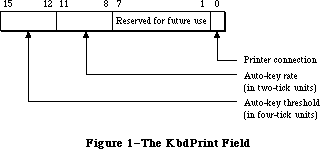 Figure 1–The KbdPrint Field
Bits 0-3 of the volClik field (Figure 2) contain the caret-blink time, and bits 4-7 contain the double-click time; both values are stored in four-tick units. The caret-blink time is the interval between blinks of the caret that marks the insertion point in text. The double-click time is the greatest interval between a mouse-up and mouse-down event that would qualify two mouse clicks as a double-click. Bits 8-10 of the volClik field contain the speaker volume setting, which ranges from silent (0) to loud (7).
Note: The Sound Driver procedure SetSoundVol changes the speaker volume
without changing the setting in parameter RAM, so it’s possible for
the actual volume to be different from this setting.
Bits 2 and 3 of the misc field (Figure 3) contain a value from 0 to 3 designating how many times a menu item will blink when it’s chosen. Bit 4 of this field indicates whether the preferred disk to use to start up the system is in the internal (0) or the external (1) drive; if there’s any problem using the disk in the specified drive, the other drive will be used.
Figure 1–The KbdPrint Field
Bits 0-3 of the volClik field (Figure 2) contain the caret-blink time, and bits 4-7 contain the double-click time; both values are stored in four-tick units. The caret-blink time is the interval between blinks of the caret that marks the insertion point in text. The double-click time is the greatest interval between a mouse-up and mouse-down event that would qualify two mouse clicks as a double-click. Bits 8-10 of the volClik field contain the speaker volume setting, which ranges from silent (0) to loud (7).
Note: The Sound Driver procedure SetSoundVol changes the speaker volume
without changing the setting in parameter RAM, so it’s possible for
the actual volume to be different from this setting.
Bits 2 and 3 of the misc field (Figure 3) contain a value from 0 to 3 designating how many times a menu item will blink when it’s chosen. Bit 4 of this field indicates whether the preferred disk to use to start up the system is in the internal (0) or the external (1) drive; if there’s any problem using the disk in the specified drive, the other drive will be used.
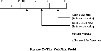 Figure 2–The VolClik Field
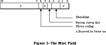 Figure 3–The Misc Field
Finally, bit 6 of the misc field designates whether mouse scaling is on (1) or off (0). If mouse scaling is on, the system looks every sixtieth of a second at whether the mouse has moved; if in that time the sum of the mouse’s horizontal and vertical changes in position is greater than the mouse-scaling threshold
(normally six pixels), then the cursor will move twice as far horizontally and vertically as it would if mouse scaling were off.
Assembly-language note: The mouse-scaling threshold is contained in the
global variable CrsrThresh.
_______________________________________________________________________________
»OPERATING SYSTEM QUEUES
_______________________________________________________________________________
Some of the information used by the Operating System is stored in data structures called queues. A queue is a list of identically structured entries linked together by pointers. Queues are used to keep track of VBL tasks, I/O requests, events, mounted volumes, and disk drives (or other block-formatted devices).
A standard Operating System queue has a header with the following structure:
TYPE QHdr = RECORD
qFlags: INTEGER; {queue flags}
qHead: QElemPtr; {first queue entry}
qTail: QElemPtr {last queue entry}
END;
QHdrPtr = ^QHdr;
QFlags contains information (usually flags) that’s different for each queue type. QHead points to the first entry in the queue, and qTail points to the last entry in the queue. The entries within each type of queue are different; the Operating System uses the following variant record to access them:
TYPE QTypes = (dummyType,
vType, {vertical retrace queue type}
ioQType, {file I/O or driver I/O queue type}
drvQType, {drive queue type}
evType, {event queue type}
fsQType); {volume-control-block queue type}
QElem = RECORD
CASE QTypes OF
vType: (vblQElem: VBLTask);
ioQType: (ioQElem: ParamBlockRec);
drvQType: (drvQElem: DrvQEl);
evType: (evQElem: EvQEl);
fsQType: (vcbQElem: VCB)
END;
QElemPtr = ^QElem;
All entries in queues, regardless of the queue type, begin with four bytes of flags followed by a pointer to the next queue entry. The entries are linked through these pointers; each one points to the pointer field in the next entry. In Pascal, the data type of the pointer is QElemPtr, and the data type of the entry begins with the pointer field. Consequently, the flag bytes are inaccessible from Pascal.
Following the pointer to the next entry, each entry contains an integer designating the queue type (for example, ORD(evType) for the event queue). The exact structure of the rest of the entry depends on the type of queue; for more information, see the chapter that discusses that queue in detail.
_______________________________________________________________________________
»GENERAL OPERATING SYSTEM DATA TYPES
_______________________________________________________________________________
This section describes two data types of general interest to users of the Operating System.
There are several places in the Operating System where you specify a four-character sequence for something, such as for file types and application signatures (described in the Finder Interface chapter). The Pascal data type for such sequences is
TYPE OSType = PACKED ARRAY[1..4] OF CHAR;
Another data type that’s used frequently in the Operating System is
TYPE OSErr = INTEGER;
This is the data type for a result code, which many Operating System routines
(including those described in this chapter) return in addition to their normal results. A result code is an integer indicating whether the routine completed its task successfully or was prevented by some error condition (or other special condition, such as reaching the end of a file). In the normal case that no error is detected, the result code is
CONST noErr = 0; {no error}
A nonzero result code (usually negative) signals an error. A list of all result codes is provided in Appendix A.
_______________________________________________________________________________
»OPERATING SYSTEM UTILITY ROUTINES
_______________________________________________________________________________
»Pointer and Handle Manipulation
These functions would be easy to duplicate with Memory Manager calls; they’re included in the Operating System Utilities as a convenience because the operations they perform are so common.
FUNCTION HandToHand (VAR theHndl: Handle) : OSErr;
Trap macro _HandToHand
On entry A0: theHndl (handle)
On exit A0: theHndl (handle)
D0: result code (word)
HandToHand copies the information to which theHndl is a handle and returns a new handle to the copy in theHndl. Since HandToHand replaces the input parameter with a new handle, you should retain the original value of the input parameter somewhere else, or you won’t be able to access it. For example:
VAR x,y: Handle;
err: OSErr;
y := x;
err := HandToHand(y)
The original handle remains in x while y becomes a different handle to an identical copy of the data.
Result codes noErr No error
memFullErr Not enough room in heap zone
nilHandleErr NIL master pointer
memWZErr Attempt to operate on a free block
FUNCTION PtrToHand (srcPtr: Ptr; VAR dstHndl: Handle;
size: LONGINT) : OSErr;
Trap macro _PtrToHand
On entry A0: srcPtr (pointer)
D0: size (long word)
On exit A0: dstHndl (handle)
D0: result code (word)
PtrToHand returns in dstHndl a newly created handle to a copy of the number of bytes specified by the size parameter, beginning at the location specified by srcPtr.
Result codes noErr No error
memFullErr Not enough room in heap zone
FUNCTION PtrToXHand (srcPtr: Ptr; dstHndl: Handle; size: LONGINT) : OSErr;
Trap macro _PtrToXHand
On entry A0: srcPtr (pointer)
A1: dstHndl (handle)
D0: size (long word)
On exit A0: dstHndl (handle)
D0: result code (word)
PtrToXHand takes the existing handle specified by dstHndl and makes it a handle to a copy of the number of bytes specified by the size parameter, beginning at the location specified by srcPtr.
Result codes noErr No error
memFullErr Not enough room in heap zone
nilHandleErr NIL master pointer
memWZErr Attempt to operate on a free block
FUNCTION HandAndHand (aHndl,bHndl: Handle) : OSErr;
Trap macro _HandAndHand
On entry A0: aHndl (handle)
A1: bHndl (handle)
On exit A0: bHndl (handle)
D0: result code (word)
HandAndHand concatenates the information to which aHndl is a handle onto the end of the information to which bHndl is a handle.
Warning: HandAndHand dereferences aHndl, so be sure to call the Memory
Manager procedure HLock to lock the block before calling HandAndHand.
Result codes noErr No error
memFullErr Not enough room in heap zone
nilHandleErr NIL master pointer
memWZErr Attempt to operate on a free block
FUNCTION PtrAndHand (pntr: Ptr; hndl: Handle; size: LONGINT) : OSErr;
Trap macro _PtrAndHand
On entry A0: pntr (pointer)
A1: hndl (handle)
D0: size (long word)
On exit A0: hndl (handle)
D0: result code (word)
PtrAndHand takes the number of bytes specified by the size parameter, beginning at the location specified by pntr, and concatenates them onto the end of the information to which hndl is a handle.
Result codes noErr No error
memFullErr Not enough room in heap zone
nilHandleErr NIL master pointer
memWZErr Attempt to operate on a free block
_______________________________________________________________________________
»String Comparison
Assembly-language note: The trap macros for these utility routines have
optional arguments corresponding to the Pascal flags
passed to the routines. When present, such an argument
sets a certain bit of the routine trap word; this is
equivalent to setting the corresponding Pascal flag to
either TRUE or FALSE, depending on the flag. The trap
macros for these routines are listed with all the
possible permutations of arguments. Whichever
permutation you use, you must type it exactly as shown.
(The syntax shown applies to the Lisa Workshop
Assembler; programmers using another development
system should consult its documentation for the proper
syntax.)
FUNCTION EqualString (aStr,bStr: Str255;
caseSens,diacSens: BOOLEAN) : BOOLEAN;
Trap macro _CmpString
_CmpString ,MARKS (sets bit 9, for diacSens=FALSE)
_CmpString ,CASE (sets bit 10, for caseSens=TRUE)
_CmpString ,MARKS,CASE (sets bits 9 and 10)
On entry A0: pointer to first character of first string
A1: pointer to first character of second string
D0: high-order word: length of first string
low-order word: length of second string
On exit D0: 0 if strings equal, 1 if strings not equal (long word)
EqualString compares the two given strings for equality on the basis of their ASCII values. If caseSens is TRUE, uppercase characters are distinguished from the corresponding lowercase characters. If diacSens is FALSE, diacritical marks are ignored during the comparison. The function returns TRUE if the strings are equal.
Note: See also the International Utilities Package function IUEqualString.
FUNCTION RelString (aStr,bStr: Str255; caseSens,diacSens: BOOLEAN) : INTEGER;
RelString is similar to EqualString except that it indicates whether the first string is less than, equal to, or greater than the second string by returning either –1, 0, or 1 respectively.
Trap macro _RelString
_RelString ,MARKS (sets bit 9, for diacSens=FALSE)
_RelString ,CASE (sets bit 10, for caseSens=TRUE)
_RelString ,MARKS,CASE (sets bits 9 and 10)
On entry A0: pointer to first character of first string
A1: pointer to first character of second string
D0: high-order word: length of first string
low-order word: length of second string
On exit D0: –1 if first string less than second, 0 if equal,
1 if first string greater than second (long word)
RelString follows the sort order described in the International Utilities Package chapter except for the reordering of the following ligatures:
Æ falls between Å and a
æ falls between å and B
Œ falls between Ø and o
œ falls between ø and P
ß falls between s and T
If diacSens is FALSE, diacritical marks are ignored; RelString strips diacriticals according to the following table:
A <-- Ä, Å, À, Ã
C <-- Ç
E <-- É
N <-- Ñ
O <-- Ö, Õ, Ø
U <-- Ü
a <-- á, à, â, ä, ã, å, ª
c <-- ç
e <-- é, è, ê, ë
i <-- í, ì, î, ï
n <-- ñ
o <-- ó, ò, ô, ö, õ, ø, º
u <-- ú, ù, û, ü
y <-- ÿ
Note: This stripping is identical to that performed by the UprString
procedure when the diacSens parameter is FALSE.
If caseSens is FALSE, the comparison is not case-sensitive; RelString performs a conversion from lower-case to upper-case characters according to the following table:
A <-- a
... <-- ...
Z <-- z
À <-- à
à <-- ã
Ä <-- ä
Å <-- å
Æ <-- æ
Ç <-- ç
É <-- é
Ñ <-- ñ
Ö <-- ö
Õ <-- õ
Ø <-- ø
Œ <-- œ
Ü <-- ü
Note: This conversion is identical to that performed by the UprString
procedure.
PROCEDURE UprString (VAR theString: Str255; diacSens: BOOLEAN);
Trap macro _UprString
_UprString ,MARKS (sets bit 9, for diacSens=FALSE)
On entry A0: pointer to first character of string
D0: length of string (word)
On exit A0: pointer to first character of string
UprString converts any lowercase letters in the given string to uppercase, returning the converted string in theString. In addition, diacritical marks are stripped from the string if diacSens is FALSE.
_______________________________________________________________________________
»Date and Time Operations
The following utilities are for reading and setting the date and time stored in the clock chip. Reading the date and time is a fairly common operation; setting it is somewhat rarer, but could be necessary for implementing a desk accessory like the Control Panel.
The date and time setting is stored as an unsigned number of seconds since midnight, January 1, 1904; you can use a utility routine to convert this to a date/time record. Date/time records are defined as follows:
TYPE DateTimeRec = RECORD
year: INTEGER; {1904 to 2040}
month: INTEGER; {1 to 12 for January to December}
day: INTEGER; {1 to 31}
hour: INTEGER; {0 to 23}
minute: INTEGER; {0 to 59}
second: INTEGER; {0 to 59}
dayOfWeek: INTEGER {1 to 7 for Sunday to Saturday}
END;
FUNCTION ReadDateTime (VAR secs: LONGINT) : OSErr;
Trap macro _ReadDateTime
On entry A0: pointer to long word secs
On exit A0: pointer to long word secs
D0: result code (word)
ReadDateTime copies the date and time stored in the clock chip to a low-memory location and returns it in the secs parameter. This routine is called at system startup; you’ll probably never need to call it yourself. Instead you’ll call GetDateTime (see below).
Assembly-language note: The low-memory location to which ReadDateTime
copies the date and time is the global variable Time.
Result codes noErr No error
clkRdErr Unable to read clock
PROCEDURE GetDateTime (VAR secs: LONGINT); [Not in ROM]
GetDateTime returns in the secs parameter the contents of the low-memory location in which the date and time setting is stored; if this setting reflects the actual current date and time, secs will contain the number of seconds between midnight, January 1, 1904 and the time that the function was called.
Note: If your application disables interrupts for longer than a second,
the number of seconds returned will not be exact.
Assembly-language note: Assembly-language programmers can just access
the global variable Time.
If you wish, you can convert the value returned by GetDateTime to a date/time record by calling the Secs2Date procedure.
Note: Passing the value returned by GetDateTime to the International
Utilities Package procedure IUDateString or IUTimeString will yield
a string representing the corresponding date or time of day,
respectively.
FUNCTION SetDateTime (secs: LONGINT) : OSErr;
Trap macro _SetDateTime
On entry D0: secs (long word)
On exit D0: result code (word)
SetDateTime takes a number of seconds since midnight, January 1, 1904, as specified by the secs parameter, and writes it to the clock chip as the current date and time. It then attempts to read the value just written and verify it by comparing it to the secs parameter.
Assembly-language note: SetDateTime updates the global variable Time to
the value of the secs parameter.
Result codes noErr No error
clkWrErr Time written did not verify
clkRdErr Unable to read clock
PROCEDURE Date2Secs (date: DateTimeRec; VAR secs: LONGINT);
Trap macro _Date2Secs
On entry A0: pointer to date/time record
On exit D0: secs (long word)
Date2Secs takes the given date/time record, converts it to the corresponding number of seconds elapsed since midnight, January 1, 1904, and returns the result in the secs parameter. The dayOfWeek field of the date/time record is ignored. The values passed in the year and month fields should be within their allowable ranges, or unpredictable results will occur. The remaining four fields of the date/time record may contain any value. For example, September 34 will be interpreted as October 4, and you could specify the 300th day of the year as January 300.
PROCEDURE Secs2Date (secs: LONGINT; VAR date: DateTimeRec);
Trap macro _Secs2Date
On entry D0: secs (long word)
On exit A0: pointer to date/time record
Secs2Date takes a number of seconds elapsed since midnight, January 1, 1904 as specified by the secs parameter, converts it to the corresponding date and time, and returns the corresponding date/time record in the date parameter.
PROCEDURE GetTime (VAR date: DateTimeRec); [Not in ROM]
GetTime takes the number of seconds elapsed since midnight, January 1, 1904
(obtained by calling GetDateTime), converts that value into a date and time (by calling Secs2Date), and returns the result in the date parameter.
Assembly-language note: From assembly language, you can pass the value
of the global variable Time to Secs2Date.
PROCEDURE SetTime (date: DateTimeRec); [Not in ROM]
SetTime takes the date and time specified by the date parameter, converts it into the corresponding number of seconds elapsed since midnight, January 1, 1904 (by calling Date2Secs), and then writes that value to the clock chip as the current date and time (by calling SetDateTime).
Assembly-language note: From assembly language, you can just call Date2Secs
and SetDateTime directly.
_______________________________________________________________________________
»Parameter RAM Operations
The following three utilities are used for reading from and writing to parameter RAM. Figure 4 illustrates the function of these three utilities; further details are given below and in the “Parameter RAM” section.
FUNCTION InitUtil : OSErr;
Trap macro _InitUtil
On exit D0: result code (word)
Figure 3–The Misc Field
Finally, bit 6 of the misc field designates whether mouse scaling is on (1) or off (0). If mouse scaling is on, the system looks every sixtieth of a second at whether the mouse has moved; if in that time the sum of the mouse’s horizontal and vertical changes in position is greater than the mouse-scaling threshold
(normally six pixels), then the cursor will move twice as far horizontally and vertically as it would if mouse scaling were off.
Assembly-language note: The mouse-scaling threshold is contained in the
global variable CrsrThresh.
_______________________________________________________________________________
»OPERATING SYSTEM QUEUES
_______________________________________________________________________________
Some of the information used by the Operating System is stored in data structures called queues. A queue is a list of identically structured entries linked together by pointers. Queues are used to keep track of VBL tasks, I/O requests, events, mounted volumes, and disk drives (or other block-formatted devices).
A standard Operating System queue has a header with the following structure:
TYPE QHdr = RECORD
qFlags: INTEGER; {queue flags}
qHead: QElemPtr; {first queue entry}
qTail: QElemPtr {last queue entry}
END;
QHdrPtr = ^QHdr;
QFlags contains information (usually flags) that’s different for each queue type. QHead points to the first entry in the queue, and qTail points to the last entry in the queue. The entries within each type of queue are different; the Operating System uses the following variant record to access them:
TYPE QTypes = (dummyType,
vType, {vertical retrace queue type}
ioQType, {file I/O or driver I/O queue type}
drvQType, {drive queue type}
evType, {event queue type}
fsQType); {volume-control-block queue type}
QElem = RECORD
CASE QTypes OF
vType: (vblQElem: VBLTask);
ioQType: (ioQElem: ParamBlockRec);
drvQType: (drvQElem: DrvQEl);
evType: (evQElem: EvQEl);
fsQType: (vcbQElem: VCB)
END;
QElemPtr = ^QElem;
All entries in queues, regardless of the queue type, begin with four bytes of flags followed by a pointer to the next queue entry. The entries are linked through these pointers; each one points to the pointer field in the next entry. In Pascal, the data type of the pointer is QElemPtr, and the data type of the entry begins with the pointer field. Consequently, the flag bytes are inaccessible from Pascal.
Following the pointer to the next entry, each entry contains an integer designating the queue type (for example, ORD(evType) for the event queue). The exact structure of the rest of the entry depends on the type of queue; for more information, see the chapter that discusses that queue in detail.
_______________________________________________________________________________
»GENERAL OPERATING SYSTEM DATA TYPES
_______________________________________________________________________________
This section describes two data types of general interest to users of the Operating System.
There are several places in the Operating System where you specify a four-character sequence for something, such as for file types and application signatures (described in the Finder Interface chapter). The Pascal data type for such sequences is
TYPE OSType = PACKED ARRAY[1..4] OF CHAR;
Another data type that’s used frequently in the Operating System is
TYPE OSErr = INTEGER;
This is the data type for a result code, which many Operating System routines
(including those described in this chapter) return in addition to their normal results. A result code is an integer indicating whether the routine completed its task successfully or was prevented by some error condition (or other special condition, such as reaching the end of a file). In the normal case that no error is detected, the result code is
CONST noErr = 0; {no error}
A nonzero result code (usually negative) signals an error. A list of all result codes is provided in Appendix A.
_______________________________________________________________________________
»OPERATING SYSTEM UTILITY ROUTINES
_______________________________________________________________________________
»Pointer and Handle Manipulation
These functions would be easy to duplicate with Memory Manager calls; they’re included in the Operating System Utilities as a convenience because the operations they perform are so common.
FUNCTION HandToHand (VAR theHndl: Handle) : OSErr;
Trap macro _HandToHand
On entry A0: theHndl (handle)
On exit A0: theHndl (handle)
D0: result code (word)
HandToHand copies the information to which theHndl is a handle and returns a new handle to the copy in theHndl. Since HandToHand replaces the input parameter with a new handle, you should retain the original value of the input parameter somewhere else, or you won’t be able to access it. For example:
VAR x,y: Handle;
err: OSErr;
y := x;
err := HandToHand(y)
The original handle remains in x while y becomes a different handle to an identical copy of the data.
Result codes noErr No error
memFullErr Not enough room in heap zone
nilHandleErr NIL master pointer
memWZErr Attempt to operate on a free block
FUNCTION PtrToHand (srcPtr: Ptr; VAR dstHndl: Handle;
size: LONGINT) : OSErr;
Trap macro _PtrToHand
On entry A0: srcPtr (pointer)
D0: size (long word)
On exit A0: dstHndl (handle)
D0: result code (word)
PtrToHand returns in dstHndl a newly created handle to a copy of the number of bytes specified by the size parameter, beginning at the location specified by srcPtr.
Result codes noErr No error
memFullErr Not enough room in heap zone
FUNCTION PtrToXHand (srcPtr: Ptr; dstHndl: Handle; size: LONGINT) : OSErr;
Trap macro _PtrToXHand
On entry A0: srcPtr (pointer)
A1: dstHndl (handle)
D0: size (long word)
On exit A0: dstHndl (handle)
D0: result code (word)
PtrToXHand takes the existing handle specified by dstHndl and makes it a handle to a copy of the number of bytes specified by the size parameter, beginning at the location specified by srcPtr.
Result codes noErr No error
memFullErr Not enough room in heap zone
nilHandleErr NIL master pointer
memWZErr Attempt to operate on a free block
FUNCTION HandAndHand (aHndl,bHndl: Handle) : OSErr;
Trap macro _HandAndHand
On entry A0: aHndl (handle)
A1: bHndl (handle)
On exit A0: bHndl (handle)
D0: result code (word)
HandAndHand concatenates the information to which aHndl is a handle onto the end of the information to which bHndl is a handle.
Warning: HandAndHand dereferences aHndl, so be sure to call the Memory
Manager procedure HLock to lock the block before calling HandAndHand.
Result codes noErr No error
memFullErr Not enough room in heap zone
nilHandleErr NIL master pointer
memWZErr Attempt to operate on a free block
FUNCTION PtrAndHand (pntr: Ptr; hndl: Handle; size: LONGINT) : OSErr;
Trap macro _PtrAndHand
On entry A0: pntr (pointer)
A1: hndl (handle)
D0: size (long word)
On exit A0: hndl (handle)
D0: result code (word)
PtrAndHand takes the number of bytes specified by the size parameter, beginning at the location specified by pntr, and concatenates them onto the end of the information to which hndl is a handle.
Result codes noErr No error
memFullErr Not enough room in heap zone
nilHandleErr NIL master pointer
memWZErr Attempt to operate on a free block
_______________________________________________________________________________
»String Comparison
Assembly-language note: The trap macros for these utility routines have
optional arguments corresponding to the Pascal flags
passed to the routines. When present, such an argument
sets a certain bit of the routine trap word; this is
equivalent to setting the corresponding Pascal flag to
either TRUE or FALSE, depending on the flag. The trap
macros for these routines are listed with all the
possible permutations of arguments. Whichever
permutation you use, you must type it exactly as shown.
(The syntax shown applies to the Lisa Workshop
Assembler; programmers using another development
system should consult its documentation for the proper
syntax.)
FUNCTION EqualString (aStr,bStr: Str255;
caseSens,diacSens: BOOLEAN) : BOOLEAN;
Trap macro _CmpString
_CmpString ,MARKS (sets bit 9, for diacSens=FALSE)
_CmpString ,CASE (sets bit 10, for caseSens=TRUE)
_CmpString ,MARKS,CASE (sets bits 9 and 10)
On entry A0: pointer to first character of first string
A1: pointer to first character of second string
D0: high-order word: length of first string
low-order word: length of second string
On exit D0: 0 if strings equal, 1 if strings not equal (long word)
EqualString compares the two given strings for equality on the basis of their ASCII values. If caseSens is TRUE, uppercase characters are distinguished from the corresponding lowercase characters. If diacSens is FALSE, diacritical marks are ignored during the comparison. The function returns TRUE if the strings are equal.
Note: See also the International Utilities Package function IUEqualString.
FUNCTION RelString (aStr,bStr: Str255; caseSens,diacSens: BOOLEAN) : INTEGER;
RelString is similar to EqualString except that it indicates whether the first string is less than, equal to, or greater than the second string by returning either –1, 0, or 1 respectively.
Trap macro _RelString
_RelString ,MARKS (sets bit 9, for diacSens=FALSE)
_RelString ,CASE (sets bit 10, for caseSens=TRUE)
_RelString ,MARKS,CASE (sets bits 9 and 10)
On entry A0: pointer to first character of first string
A1: pointer to first character of second string
D0: high-order word: length of first string
low-order word: length of second string
On exit D0: –1 if first string less than second, 0 if equal,
1 if first string greater than second (long word)
RelString follows the sort order described in the International Utilities Package chapter except for the reordering of the following ligatures:
Æ falls between Å and a
æ falls between å and B
Œ falls between Ø and o
œ falls between ø and P
ß falls between s and T
If diacSens is FALSE, diacritical marks are ignored; RelString strips diacriticals according to the following table:
A <-- Ä, Å, À, Ã
C <-- Ç
E <-- É
N <-- Ñ
O <-- Ö, Õ, Ø
U <-- Ü
a <-- á, à, â, ä, ã, å, ª
c <-- ç
e <-- é, è, ê, ë
i <-- í, ì, î, ï
n <-- ñ
o <-- ó, ò, ô, ö, õ, ø, º
u <-- ú, ù, û, ü
y <-- ÿ
Note: This stripping is identical to that performed by the UprString
procedure when the diacSens parameter is FALSE.
If caseSens is FALSE, the comparison is not case-sensitive; RelString performs a conversion from lower-case to upper-case characters according to the following table:
A <-- a
... <-- ...
Z <-- z
À <-- à
à <-- ã
Ä <-- ä
Å <-- å
Æ <-- æ
Ç <-- ç
É <-- é
Ñ <-- ñ
Ö <-- ö
Õ <-- õ
Ø <-- ø
Œ <-- œ
Ü <-- ü
Note: This conversion is identical to that performed by the UprString
procedure.
PROCEDURE UprString (VAR theString: Str255; diacSens: BOOLEAN);
Trap macro _UprString
_UprString ,MARKS (sets bit 9, for diacSens=FALSE)
On entry A0: pointer to first character of string
D0: length of string (word)
On exit A0: pointer to first character of string
UprString converts any lowercase letters in the given string to uppercase, returning the converted string in theString. In addition, diacritical marks are stripped from the string if diacSens is FALSE.
_______________________________________________________________________________
»Date and Time Operations
The following utilities are for reading and setting the date and time stored in the clock chip. Reading the date and time is a fairly common operation; setting it is somewhat rarer, but could be necessary for implementing a desk accessory like the Control Panel.
The date and time setting is stored as an unsigned number of seconds since midnight, January 1, 1904; you can use a utility routine to convert this to a date/time record. Date/time records are defined as follows:
TYPE DateTimeRec = RECORD
year: INTEGER; {1904 to 2040}
month: INTEGER; {1 to 12 for January to December}
day: INTEGER; {1 to 31}
hour: INTEGER; {0 to 23}
minute: INTEGER; {0 to 59}
second: INTEGER; {0 to 59}
dayOfWeek: INTEGER {1 to 7 for Sunday to Saturday}
END;
FUNCTION ReadDateTime (VAR secs: LONGINT) : OSErr;
Trap macro _ReadDateTime
On entry A0: pointer to long word secs
On exit A0: pointer to long word secs
D0: result code (word)
ReadDateTime copies the date and time stored in the clock chip to a low-memory location and returns it in the secs parameter. This routine is called at system startup; you’ll probably never need to call it yourself. Instead you’ll call GetDateTime (see below).
Assembly-language note: The low-memory location to which ReadDateTime
copies the date and time is the global variable Time.
Result codes noErr No error
clkRdErr Unable to read clock
PROCEDURE GetDateTime (VAR secs: LONGINT); [Not in ROM]
GetDateTime returns in the secs parameter the contents of the low-memory location in which the date and time setting is stored; if this setting reflects the actual current date and time, secs will contain the number of seconds between midnight, January 1, 1904 and the time that the function was called.
Note: If your application disables interrupts for longer than a second,
the number of seconds returned will not be exact.
Assembly-language note: Assembly-language programmers can just access
the global variable Time.
If you wish, you can convert the value returned by GetDateTime to a date/time record by calling the Secs2Date procedure.
Note: Passing the value returned by GetDateTime to the International
Utilities Package procedure IUDateString or IUTimeString will yield
a string representing the corresponding date or time of day,
respectively.
FUNCTION SetDateTime (secs: LONGINT) : OSErr;
Trap macro _SetDateTime
On entry D0: secs (long word)
On exit D0: result code (word)
SetDateTime takes a number of seconds since midnight, January 1, 1904, as specified by the secs parameter, and writes it to the clock chip as the current date and time. It then attempts to read the value just written and verify it by comparing it to the secs parameter.
Assembly-language note: SetDateTime updates the global variable Time to
the value of the secs parameter.
Result codes noErr No error
clkWrErr Time written did not verify
clkRdErr Unable to read clock
PROCEDURE Date2Secs (date: DateTimeRec; VAR secs: LONGINT);
Trap macro _Date2Secs
On entry A0: pointer to date/time record
On exit D0: secs (long word)
Date2Secs takes the given date/time record, converts it to the corresponding number of seconds elapsed since midnight, January 1, 1904, and returns the result in the secs parameter. The dayOfWeek field of the date/time record is ignored. The values passed in the year and month fields should be within their allowable ranges, or unpredictable results will occur. The remaining four fields of the date/time record may contain any value. For example, September 34 will be interpreted as October 4, and you could specify the 300th day of the year as January 300.
PROCEDURE Secs2Date (secs: LONGINT; VAR date: DateTimeRec);
Trap macro _Secs2Date
On entry D0: secs (long word)
On exit A0: pointer to date/time record
Secs2Date takes a number of seconds elapsed since midnight, January 1, 1904 as specified by the secs parameter, converts it to the corresponding date and time, and returns the corresponding date/time record in the date parameter.
PROCEDURE GetTime (VAR date: DateTimeRec); [Not in ROM]
GetTime takes the number of seconds elapsed since midnight, January 1, 1904
(obtained by calling GetDateTime), converts that value into a date and time (by calling Secs2Date), and returns the result in the date parameter.
Assembly-language note: From assembly language, you can pass the value
of the global variable Time to Secs2Date.
PROCEDURE SetTime (date: DateTimeRec); [Not in ROM]
SetTime takes the date and time specified by the date parameter, converts it into the corresponding number of seconds elapsed since midnight, January 1, 1904 (by calling Date2Secs), and then writes that value to the clock chip as the current date and time (by calling SetDateTime).
Assembly-language note: From assembly language, you can just call Date2Secs
and SetDateTime directly.
_______________________________________________________________________________
»Parameter RAM Operations
The following three utilities are used for reading from and writing to parameter RAM. Figure 4 illustrates the function of these three utilities; further details are given below and in the “Parameter RAM” section.
FUNCTION InitUtil : OSErr;
Trap macro _InitUtil
On exit D0: result code (word)
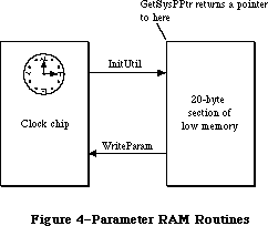 Figure 4–Parameter RAM Routines
InitUtil copies the contents of parameter RAM into 20 bytes of low memory and copies the date and time from the clock chip into its own low-memory location. This routine is called at system startup; you’ll probably never need to call it yourself.
Assembly-language note: InitUtil copies parameter RAM into 20 bytes starting
at the address SysParam and copies the date and time
into the global variable Time.
If the validity status in parameter RAM is not $A8 when InitUtil is called, an error is returned as the result code, and the default values (given in the
“Parameter RAM” section) are read into the low-memory copy of parameter RAM; these values are then written to the clock chip itself.
Result codes noErr No error
prInitErr Validity status not $A8
FUNCTION GetSysPPtr : SysPPtr; [Not in ROM]
GetSysPPtr returns a pointer to the low-memory copy of parameter RAM. You can examine the values stored in its various fields, or change them before calling WriteParam (below).
Assembly-language note: Assembly-language programmers can simply access the
global variables corresponding to the low-memory copy
of parameter RAM. These variables, which begin at the
address SysParam, are listed in the summary.
FUNCTION WriteParam : OSErr;
Trap macro _WriteParam
On entry A0: SysParam (pointer)
D0: MinusOne (long word)
(You have to pass the values of these global variables for
historical reasons.)
On exit D0: result code (word)
WriteParam writes the low-memory copy of parameter RAM to the clock chip. You should previously have called GetSysPPtr and changed selected values as desired.
WriteParam also attempts to verify the values written by reading them back in and comparing them to the values in the low-memory copy.
Note: If you’ve accidentally written incorrect values into parameter RAM,
the system may not be able to start up. If this happens, you can reset
parameter RAM by removing the battery, letting the Macintosh sit turned
off for about five minutes, and then putting the battery back in.
Result codes noErr No error
prWrErr Parameter RAM written did not verify
_______________________________________________________________________________
»Queue Manipulation
This section describes utilities that advanced programmers may want to use for adding entries to or deleting entries from an Operating System queue. Normally you won’t need to use these utilities, since queues are manipulated for you as necessary by routines that need to deal with them.
PROCEDURE Enqueue (qEntry: QElemPtr; theQueue: QHdrPtr);
Trap macro _Enqueue
On entry A0: qEntry (pointer)
A1: theQueue (pointer)
On exit A1: theQueue (pointer)
Enqueue adds the queue entry pointed to by qEntry to the end of the queue specified by theQueue.
Note: Interrupts are disabled for a short time while the queue is updated.
FUNCTION Dequeue (qEntry: QElemPtr; theQueue: QHdrPtr) : OSErr;
Trap macro _Dequeue
On entry A0: qEntry (pointer)
A1: theQueue (pointer)
On exit A1: theQueue (pointer)
D0: result code (word)
Dequeue removes the queue entry pointed to by qEntry from the queue specified by theQueue (without deallocating the entry) and adjusts other entries in the queue accordingly.
Note: The note under Enqueue above also applies here. In this case, the
amount of time interrupts are disabled depends on the length of the
queue and the position of the entry in the queue.
Note: To remove all entries from a queue, you can just clear all the fields
of the queue’s header.
Result codes noErr No error
qErr Entry not in specified queue
_______________________________________________________________________________
»Trap Dispatch Table Utilities
The Operating System Utilities include two routines for manipulating the trap dispatch table, which is described in detail in the Using Assembly Language chapter. Using these routines, you can intercept calls to an Operating System or Toolbox routine and do some pre- or post-processing of your own: Call GetTrapAddress to get the address of the original routine, save that address for later use, and call SetTrapAddress to install your own version of the routine in the dispatch table. Before or after its own processing, the new version of the routine can use the saved address to call the original version.
Warning: You can replace as well as intercept existing routines; in any case,
you should be absolutely sure you know what you’re doing. Remember
that some calls that aren’t in ROM do some processing of their own
before invoking a trap macro (for example, FSOpen eventually invokes
_Open, and IUCompString invokes the macro for IUMagString). Also, a
number of ROM routines have been patched with corrected versions in
RAM; if you intercept a patched routine, you must not do any
processing after the existing patch, and you must be sure to
preserve the registers and the stack (or the system won’t work
properly).
Assembly-language note: You can tell whether a routine is patched by comparing
its address to the global variable ROMBase; if the
address is less than ROMBase, the routine is patched.
In addition, you can use GetTrapAddress to save time in critical sections of your program by calling an Operating System or Toolbox routine directly, avoiding the overhead of a normal trap dispatch.
FUNCTION GetTrapAddress (trapNum: INTEGER) : LONGINT;
Trap macro _GetTrapAddress
On entry D0: trapNum (word)
On exit A0: address of routine
GetTrapAddress returns the address of a routine currently installed in the trap dispatch table under the trap number designated by trapNum. To find out the trap number for a particular routine, see Appendix C.
Assembly-language note: When you use this technique to bypass the trap
dispatcher, you don’t get the extra level of register
saving. The routine itself will preserve A2-A6 and
D3-D7, but if you want any other registers preserved
across the call you have to save and restore them
yourself.
PROCEDURE SetTrapAddress (trapAddr: LONGINT; trapNum: INTEGER);
Trap macro _SetTrapAddress
On entry A0: trapAddr (address)
D0: trapNum (word)
SetTrapAddress installs in the trap dispatch table a routine whose address is trapAddr; this routine is installed under the trap number designated by trapNum.
Warning: Since the trap dispatch table can address locations within a range
of only 64K bytes from the beginning of the system heap, the routine
you install should be in the system heap.
Assembly-language note: To use GetTrapAddress and SetTrapAddress with
128K ROM routines, set bit 9 of the trap word to
indicate the new trap numbering. The state of bit
10 then determines whether the intended trap is a
Toolbox or Operating System trap. You can set these
two bits with the arguments NEWOS and NEWTOOL.
Of course, the 64K ROM versions of GetTrapAddress and
SetTrapAddress will fail if applied to traps that
exist only in the 128K ROM.
The NGetTrapAddress and NSetTrapAddress routines list
the possible permutations of arguments. (The syntax
shown applies to the Lisa Workshop Assembler;
programmers using another development system should
consult its documentation for the proper syntax.)
FUNCTION NGetTrapAddress (trapNum: INTEGER; tType: TrapType) : LongInt;
[Not in ROM]
NGetTrapAddress is identical to GetTrapAddress except that it requires you to specify in tType whether the given routine is an Operating System or a Toolbox trap.
Trap macro _GetTrapAddress ,NEWOS (bit 9 set, bit 10 clear)
_GetTrapAddress ,NEWTOOL (bit 9 set, bit 10 set)
On entry D0: trapNum (word)
On exit A0: address of routine
PROCEDURE NSetTrapAddress (trapAddr: LongInt; trapNum: INTEGER;
tType: TrapType); [Not in ROM]
NSetTrapAddress is identical to SetTrapAddress except that it requires you to specify in tType whether the given routine is an Operating System or a Toolbox trap.
Trap macro _SetTrapAddress ,NEWOS (bit 9 set, bit 10 clear)
_SetTrapAddress ,NEWTOOL (bit 9 set, bit 10 set)
On entry A0: trapAddr (address)
D0: trapNum (word)
_______________________________________________________________________________
»Miscellaneous Utilities
PROCEDURE Delay (numTicks: LONGINT; VAR finalTicks: LONGINT);
Trap macro _Delay
On entry A0: numTicks (long word)
On exit D0: finalTicks (long word)
Delay causes the system to wait for the number of ticks (sixtieths of a second) specified by numTicks, and returns in finalTicks the total number of ticks from system startup to the end of the delay.
Warning: Don’t rely on the duration of the delay being exact; it will usually
be accurate to within one tick, but may be off by more than that.
The Delay procedure enables all interrupts and checks the tick count
that’s incremented during the vertical retrace interrupt; however,
it’s possible for this interrupt to be disabled by other interrupts,
in which case the duration of the delay will not be exactly what you
requested.
Assembly-language note: On exit from this procedure, register D0 contains the
value of the global variable Ticks as measured at the
end of the delay.
PROCEDURE SysBeep (duration: INTEGER);
SysBeep causes the system to beep for approximately the number of ticks specified by the duration parameter. The sound decays from loud to soft; after about five seconds it’s inaudible. The initial volume of the beep depends on the current speaker volume setting, which the user can adjust with the Control Panel desk accessory. If the speaker volume has been set to 0 (silent), SysBeep instead causes the menu bar to blink once.
Assembly-language note: Unlike all other Operating System Utilities, this
procedure is stack-based.
PROCEDURE Environs (VAR rom,machine: INTEGER) [Not in ROM]
In the rom parameter, Environs returns the current ROM version number (for a Macintosh XL, the version number of the ROM image installed by MacWorks). To use the 128K ROM information described in this volume, the version number should be greater than or equal to 117 ($75). In the machine parameter, Environs returns an indication of which machine is in use, as follows:
CONST macXLMachine = 0; {Macintosh XL}
macMachine = 1; {Macintosh 128K, 512K, 512K upgraded, }
{ 512K enhanced, or Macintosh Plus}
Note: The machine parameter does not distinguish between the Macintosh 128K,
512K, 512K upgraded, 512K enhanced, and Macintosh Plus.
Assembly-language note: From assembly language, you can get this information
from the word that’s at an offset of 8 from the
beginning of ROM (which is stored in the global
variable ROMBase). The format of this word is $00xx
for the Macintosh 128K, 512K, 512K enhanced, or
Macintosh Plus, and $xxFF for the Macintosh XL, where
xx is the ROM version number. (The ROM version number
will always be between $01 and $FE.)
PROCEDURE Restart; [Not in ROM]
This procedure restarts the system.
Assembly-language note: From assembly language, you can give the following
instructions to restart the system:
MOVE.L ROMBase,A0
JMP $0A(A0)
Note: The procedures SetUpA5 and RestoreA5 were formerly documented in this
chapter; however, two routines with more functionality are now available
with the MPW 3.0 and later libraries. The routines SetCurrentA5 and
SetA5 are documented in Macintosh Technical Note #208.
X-Ref: Technical Note #208
FUNCTION GetMMUMode (VAR mode: INTEGER); [Not in ROM]
GetMMUMode returns the address translation mode currently in use.
Assembly-language note: Assembly-language programmers can determine the
current address mode by testing the contents of
the global variable MMU32Bit; it’s TRUE if 32-bit
mode is in effect.
X-Ref: Technical Note #228
PROCEDURE SwapMMUMode (VAR mode: Byte);
Trap macro _SwapMMUMode
On entry D0: mode (byte)
On exit D0: mode (byte)
SwapMMUMode sets the address translation mode to that specified by the mode parameter. The mode in use prior to the call is returned in mode, and can be restored with another call to SwapMMUMode.
FUNCTION StripAddress (theAddress: Ptr) : Ptr;
Trap macro _StripAddress
On entry D0: theAddress (pointer)
On exit D0: function result (pointer)
The original description of StripAddress was incorrect. Technical Note #213 correctly documents this function.
X-Ref: Technical Note #213
_______________________________________________________________________________
»SUMMARY OF THE OPERATING SYSTEM UTILITIES
_______________________________________________________________________________
Constants
CONST
{ Values returned by Environs procedure }
macXLMachine = 0; {Macintosh XL}
macMachine = 1; {Macintosh 128K, 512K, 512K upgraded, }
{ 512K enhanced, or Macintosh Plus}
{ Result codes }
clkRdErr = -85; {unable to read clock}
clkWrErr = -86; {time written did not verify}
memFullErr = -108; {not enough room in heap zone}
memWZErr = -111; {attempt to operate on a free block}
nilHandleErr = -109; {NIL master pointer}
noErr = 0; {no error}
prInitErr = -88; {validity status is not $A8}
prWrErr = -87; {parameter RAM written did not verify}
qErr = -1 {entry not in specified queue}
{ Addressing modes }
false32b = 0; {24-bit addressing mode}
true32b = 1; {32-bit addressing mode}
_______________________________________________________________________________
Data Types
TYPE
OSType = PACKED ARRAY[1..4] OF CHAR;
OSErr = INTEGER;
SysPPtr = ^SysParmType;
SysParmType = RECORD
valid: Byte; {validity status}
aTalkA: Byte; {AppleTalk node ID hint for modem }
{ port}
aTalkB: Byte; {AppleTalk node ID hint for printer }
{ port}
config: Byte; {use types for serial ports}
portA: INTEGER; {modem port configuration}
portB: INTEGER; {printer port configuration}
alarm: LONGINT; {alarm setting}
font: INTEGER; {application font number minus 1}
kbdPrint: INTEGER; {auto-key settings, printer }
{ connection}
volClik: INTEGER; {speaker volume, double-click, }
{ caret blink}
misc: INTEGER {mouse scaling, startup disk, }
{ menu blink}
END;
QHdrPtr = ^QHdr;
QHdr = RECORD
qFlags: INTEGER; {queue flags}
qHead: QElemPtr; {first queue entry}
qTail: QElemPtr {last queue entry}
END;
QTypes = (dummyType,
vType, {vertical retrace queue type}
ioQType, {file I/O or driver I/O queue type}
drvQType, {drive queue type}
evType, {event queue type}
fsQType); {volume-control-block queue type}
QElemPtr = ^QElem;
QElem = RECORD
CASE QTypes OF
vType: (vblQElem: VBLTask);
ioQType: (ioQElem: ParamBlockRec);
drvQType: (drvQElem: DrvQEl);
evType: (evQElem: EvQEl);
fsQType: (vcbQElem: VCB)
END;
DateTimeRec = RECORD
year: INTEGER; {1904 to 2040}
month: INTEGER; {1 to 12 for January to December}
day: INTEGER; {1 to 31}
hour: INTEGER; {0 to 23}
minute: INTEGER; {0 to 59}
second: INTEGER; {0 to 59}
dayOfWeek: INTEGER {1 to 7 for Sunday to Saturday}
END;
TrapType = (OSTrap,ToolTrap);
_______________________________________________________________________________
Routines
Pointer and Handle Manipulation
FUNCTION HandToHand (VAR theHndl: Handle) : OSErr;
FUNCTION PtrToHand (srcPtr: Ptr; VAR dstHndl: Handle;
size: LONGINT) : OSErr;
FUNCTION PtrToXHand (srcPtr: Ptr; dstHndl: Handle;
size: LONGINT) : OSErr;
FUNCTION HandAndHand (aHndl,bHndl: Handle) : OSErr;
FUNCTION PtrAndHand (pntr: Ptr; hndl: Handle; size: LONGINT) : OSErr;
String Comparison
FUNCTION EqualString (aStr,bStr: Str255;
caseSens,diacSens: BOOLEAN) : BOOLEAN;
FUNCTION RelString (aStr,bStr: Str255;
caseSens,diacSens: BOOLEAN) : INTEGER;
PROCEDURE UprString (VAR theString: Str255; diacSens: BOOLEAN);
Date and Time Operations
FUNCTION ReadDateTime (VAR secs: LONGINT) : OSErr;
PROCEDURE GetDateTime (VAR secs: LONGINT); [Not in ROM]
FUNCTION SetDateTime (secs: LONGINT) : OSErr;
PROCEDURE Date2Secs (date: DateTimeRec; VAR secs: LONGINT);
PROCEDURE Secs2Date (secs: LONGINT; VAR date: DateTimeRec);
PROCEDURE GetTime (VAR date: DateTimeRec); [Not in ROM]
PROCEDURE SetTime (date: DateTimeRec); [Not in ROM]
Parameter RAM Operations
FUNCTION InitUtil : OSErr;
FUNCTION GetSysPPtr : SysPPtr; [Not in ROM]
FUNCTION WriteParam : OSErr;
Queue Manipulation
PROCEDURE Enqueue (qEntry: QElemPtr; theQueue: QHdrPtr);
FUNCTION Dequeue (qEntry: QElemPtr; theQueue: QHdrPtr) : OSErr;
Trap Dispatch Table Utilities
PROCEDURE SetTrapAddress (trapAddr: LONGINT; trapNum: INTEGER);
FUNCTION GetTrapAddress (trapNum: INTEGER) : LONGINT;
FUNCTION NGetTrapAddress (trapNum: INTEGER;
tType: TrapType) : LongInt; [Not in ROM]
PROCEDURE NSetTrapAddress (trapAddr: LongInt; trapNum: INTEGER;
tType: TrapType); [Not in ROM]
Miscellaneous Utilities
PROCEDURE Delay (numTicks: LONGINT; VAR finalTicks: LONGINT);
PROCEDURE SysBeep (duration: INTEGER);
PROCEDURE Environs (VAR rom,machine: INTEGER) [Not in ROM]
PROCEDURE Restart; [Not in ROM]
PROCEDURE GetMMUMode (VAR mode: Byte);
PROCEDURE SwapMMUMode (VAR mode: Byte);
FUNCTION StripAddress (theAddress: LONGINT) : LONGINT;
Default Parameter RAM Values
Parameter Default value
Validity status $A8
Node ID hint for modem port 0
Node ID hint for printer port 0
Use types for serial ports 0 (both ports)
Modem port configuration 9600 baud, 8 data bits, 2 stop bits,
no parity
Printer port configuration Same as for modem port
Alarm setting 0 (midnight, January 1, 1904)
Application font number minus 1 2 (Geneva)
Auto-key threshold 6 (24 ticks)
Auto-key rate 3 (6 ticks)
Printer connection 0 (printer port)
Speaker volume 3 (medium)
Double-click time 8 (32 ticks)
Caret-blink time 8 (32 ticks)
Mouse scaling 1 (on)
Preferred system startup disk 0 (internal drive)
Menu blink 3
_______________________________________________________________________________
Assembly-Language Information
Constants
; Result codes
clkRdErr .EQU –85 ;unable to read clock
clkWrErr .EQU –86 ;time written did not verify
memFullErr .EQU –108 ;not enough room in heap zone
memWZErr .EQU –111 ;attempt to operate on a free block
nilHandleErr .EQU –109 ;NIL master pointer
noErr .EQU 0 ;no error
prInitErr .EQU –88 ;validity status is not $A8
prWrErr .EQU –87 ;parameter RAM written did not verify
qErr .EQU –1 ;entry not in specified queue
; Addressing modes
false32b .EQU 0 ;24-bit addressing mode
true32b .EQU 1 ;32-bit addressing mode
; Queue types
vType .EQU 1 ;vertical retrace queue type
ioQType .EQU 2 ;file I/O or driver I/O queue type
drvQType .EQU 3 ;drive queue type
evType .EQU 4 ;event queue type
fsQType .EQU 5 ;volume-control-block queue type
Queue Data Structure
qFlags Queue flags (word)
qHead Pointer to first queue entry
qTail Pointer to last queue entry
Date/Time Record Data Structure
dtYear 1904 to 2040 (word)
dtMonth 1 to 12 for January to December (word)
dtDay 1 to 31 (word)
dtHour 0 to 23 (word)
dtMinute 0 to 59 (word)
dtSecond 0 to 59 (word)
dtDayOfWeek 1 to 7 for Sunday to Saturday (word)
Routines
Trap macro On entry On exit
_HandToHand A0: theHndl (handle) A0: theHndl (handle)
D0: result code(word)
_PtrToHand A0: srcPtr (ptr) A0: dstHndl (handle)
D0: size (long) D0: result code (word)
_PtrToXHand A0: srcPtr (ptr) A0: dstHndl (handle)
A1: dstHndl (handle) D0: result code (word)
D0: size (long)
_HandAndHand A0: aHndl (handle) A0: bHndl (handle)
A1: bHndl (handle) D0: result code (word)
_PtrAndHand A0: pntr (ptr) A0: hndl (handle)
A1: hndl (handle) D0: result code (word)
D0: size (long)
_CmpString _CmpString ,MARKS sets bit 9, for diacSens=FALSE
_CmpString ,CASE sets bit 10, for caseSens=TRUE
_CmpString ,MARKS,CASE sets bits 9 and 10
A0: ptr to first string D0: 0 if equal, 1 if
A1: ptr to second string not equal (long)
D0: high word: length of
first string
low word: length of
second string
_RelString _RelString ,MARKS
(sets bit 9, for diacSens=FALSE)
_RelString ,CASE
(sets bit 10, for caseSens=TRUE)
_RelString ,MARKS,CASE
(sets bits 9 and 10)
A0: ptr to first string D0: –1 if first less than
A1: ptr to second string second, 0 if equal, 1 if
D0: high word: length of first greater than
first string second (long)
low word: length of
second string
_UprString _UprString ,MARKS sets bit 9, for diacSens=FALSE
A0: ptr to string A0: ptr to string
D0: length of string (word)
_ReadDateTime A0: ptr to long word secs A0: ptr to long word secs
D0: result code (word)
_SetDateTime D0: secs (long) D0: result code (word)
_Date2Secs A0: ptr to date/time record D0: secs (long)
_Secs2Date D0: secs (long) A0: ptr to date/time record
_InitUtil D0: result code (word)
_WriteParam A0: SysParam (ptr) D0: result code (word)
D0: MinusOne (long)
_Enqueue A0: qEntry (ptr) A1: theQueue (ptr)
A1: theQueue (ptr)
_Dequeue A0: qEntry (ptr) A1: theQueue (ptr)
A1: theQueue (ptr) D0: result code (word)
_GetTrapAddress _GetTrapAddress ,NEWOS
(bit 9 set, bit 10 clear)
_GetTrapAddress ,NEWTOOL
(bit 9 set, bit 10 set)
D0: trapNum (word) A0: address of routine
_SetTrapAddress _SetTrapAddress ,NEWOS
(bit 9 set, bit 10 clear)
_SetTrapAddress ,NEWTOOL
(bit 9 set, bit 10 set)
A0: trapAddr (address)
D0: trapNum (word)
_Delay A0: numTicks (long) D0: finalTicks (long)
_SysBeep stack: duration (word)
_SwapMMUMode D0: mode (byte) D0: mode (byte)
_StripAddress D0: the Address (long) D0: function result (long)
Variables
SysParam Low-memory copy of parameter RAM (20 bytes)
SPValid Validity status (byte)
SPATalkA AppleTalk node ID hint for modem port (byte)
SPATalkB AppleTalk node ID hint for printer port (byte)
SPConfig Use types for serial ports (byte)
SPPortA Modem port configuration (word)
SPPortB Printer port configuration (word)
SPAlarm Alarm setting (long)
SPFont Application font number minus 1 (word)
SPKbd Auto-key threshold and rate (byte)
SPPrint Printer connection (byte)
SPVolCtl Speaker volume (byte)
SPClikCaret Double-click and caret-blink times (byte)
SPMisc2 Mouse scaling, system startup disk, menu blink (byte)
CrsrThresh Mouse-scaling threshold (word)
Time Seconds since midnight, January 1, 1904 (long)
ROMBase Base address of ROM
MMU32Bit Current address mode (byte)
Further Reference:
_______________________________________________________________________________
Technical Note #25, Don’t Depend on Register A5 Within Trap Patches
Technical Note #156, Checking for Specific Functionality
Technical Note #184, Notification Manager
Technical Note #208, Setting and Restoring A5
Technical Note #213, _StripAddress: The Untold Story
Technical Note #228, Use Care When Swapping MMU Mode
Technical Note #261, Cache As Cache Can
Figure 4–Parameter RAM Routines
InitUtil copies the contents of parameter RAM into 20 bytes of low memory and copies the date and time from the clock chip into its own low-memory location. This routine is called at system startup; you’ll probably never need to call it yourself.
Assembly-language note: InitUtil copies parameter RAM into 20 bytes starting
at the address SysParam and copies the date and time
into the global variable Time.
If the validity status in parameter RAM is not $A8 when InitUtil is called, an error is returned as the result code, and the default values (given in the
“Parameter RAM” section) are read into the low-memory copy of parameter RAM; these values are then written to the clock chip itself.
Result codes noErr No error
prInitErr Validity status not $A8
FUNCTION GetSysPPtr : SysPPtr; [Not in ROM]
GetSysPPtr returns a pointer to the low-memory copy of parameter RAM. You can examine the values stored in its various fields, or change them before calling WriteParam (below).
Assembly-language note: Assembly-language programmers can simply access the
global variables corresponding to the low-memory copy
of parameter RAM. These variables, which begin at the
address SysParam, are listed in the summary.
FUNCTION WriteParam : OSErr;
Trap macro _WriteParam
On entry A0: SysParam (pointer)
D0: MinusOne (long word)
(You have to pass the values of these global variables for
historical reasons.)
On exit D0: result code (word)
WriteParam writes the low-memory copy of parameter RAM to the clock chip. You should previously have called GetSysPPtr and changed selected values as desired.
WriteParam also attempts to verify the values written by reading them back in and comparing them to the values in the low-memory copy.
Note: If you’ve accidentally written incorrect values into parameter RAM,
the system may not be able to start up. If this happens, you can reset
parameter RAM by removing the battery, letting the Macintosh sit turned
off for about five minutes, and then putting the battery back in.
Result codes noErr No error
prWrErr Parameter RAM written did not verify
_______________________________________________________________________________
»Queue Manipulation
This section describes utilities that advanced programmers may want to use for adding entries to or deleting entries from an Operating System queue. Normally you won’t need to use these utilities, since queues are manipulated for you as necessary by routines that need to deal with them.
PROCEDURE Enqueue (qEntry: QElemPtr; theQueue: QHdrPtr);
Trap macro _Enqueue
On entry A0: qEntry (pointer)
A1: theQueue (pointer)
On exit A1: theQueue (pointer)
Enqueue adds the queue entry pointed to by qEntry to the end of the queue specified by theQueue.
Note: Interrupts are disabled for a short time while the queue is updated.
FUNCTION Dequeue (qEntry: QElemPtr; theQueue: QHdrPtr) : OSErr;
Trap macro _Dequeue
On entry A0: qEntry (pointer)
A1: theQueue (pointer)
On exit A1: theQueue (pointer)
D0: result code (word)
Dequeue removes the queue entry pointed to by qEntry from the queue specified by theQueue (without deallocating the entry) and adjusts other entries in the queue accordingly.
Note: The note under Enqueue above also applies here. In this case, the
amount of time interrupts are disabled depends on the length of the
queue and the position of the entry in the queue.
Note: To remove all entries from a queue, you can just clear all the fields
of the queue’s header.
Result codes noErr No error
qErr Entry not in specified queue
_______________________________________________________________________________
»Trap Dispatch Table Utilities
The Operating System Utilities include two routines for manipulating the trap dispatch table, which is described in detail in the Using Assembly Language chapter. Using these routines, you can intercept calls to an Operating System or Toolbox routine and do some pre- or post-processing of your own: Call GetTrapAddress to get the address of the original routine, save that address for later use, and call SetTrapAddress to install your own version of the routine in the dispatch table. Before or after its own processing, the new version of the routine can use the saved address to call the original version.
Warning: You can replace as well as intercept existing routines; in any case,
you should be absolutely sure you know what you’re doing. Remember
that some calls that aren’t in ROM do some processing of their own
before invoking a trap macro (for example, FSOpen eventually invokes
_Open, and IUCompString invokes the macro for IUMagString). Also, a
number of ROM routines have been patched with corrected versions in
RAM; if you intercept a patched routine, you must not do any
processing after the existing patch, and you must be sure to
preserve the registers and the stack (or the system won’t work
properly).
Assembly-language note: You can tell whether a routine is patched by comparing
its address to the global variable ROMBase; if the
address is less than ROMBase, the routine is patched.
In addition, you can use GetTrapAddress to save time in critical sections of your program by calling an Operating System or Toolbox routine directly, avoiding the overhead of a normal trap dispatch.
FUNCTION GetTrapAddress (trapNum: INTEGER) : LONGINT;
Trap macro _GetTrapAddress
On entry D0: trapNum (word)
On exit A0: address of routine
GetTrapAddress returns the address of a routine currently installed in the trap dispatch table under the trap number designated by trapNum. To find out the trap number for a particular routine, see Appendix C.
Assembly-language note: When you use this technique to bypass the trap
dispatcher, you don’t get the extra level of register
saving. The routine itself will preserve A2-A6 and
D3-D7, but if you want any other registers preserved
across the call you have to save and restore them
yourself.
PROCEDURE SetTrapAddress (trapAddr: LONGINT; trapNum: INTEGER);
Trap macro _SetTrapAddress
On entry A0: trapAddr (address)
D0: trapNum (word)
SetTrapAddress installs in the trap dispatch table a routine whose address is trapAddr; this routine is installed under the trap number designated by trapNum.
Warning: Since the trap dispatch table can address locations within a range
of only 64K bytes from the beginning of the system heap, the routine
you install should be in the system heap.
Assembly-language note: To use GetTrapAddress and SetTrapAddress with
128K ROM routines, set bit 9 of the trap word to
indicate the new trap numbering. The state of bit
10 then determines whether the intended trap is a
Toolbox or Operating System trap. You can set these
two bits with the arguments NEWOS and NEWTOOL.
Of course, the 64K ROM versions of GetTrapAddress and
SetTrapAddress will fail if applied to traps that
exist only in the 128K ROM.
The NGetTrapAddress and NSetTrapAddress routines list
the possible permutations of arguments. (The syntax
shown applies to the Lisa Workshop Assembler;
programmers using another development system should
consult its documentation for the proper syntax.)
FUNCTION NGetTrapAddress (trapNum: INTEGER; tType: TrapType) : LongInt;
[Not in ROM]
NGetTrapAddress is identical to GetTrapAddress except that it requires you to specify in tType whether the given routine is an Operating System or a Toolbox trap.
Trap macro _GetTrapAddress ,NEWOS (bit 9 set, bit 10 clear)
_GetTrapAddress ,NEWTOOL (bit 9 set, bit 10 set)
On entry D0: trapNum (word)
On exit A0: address of routine
PROCEDURE NSetTrapAddress (trapAddr: LongInt; trapNum: INTEGER;
tType: TrapType); [Not in ROM]
NSetTrapAddress is identical to SetTrapAddress except that it requires you to specify in tType whether the given routine is an Operating System or a Toolbox trap.
Trap macro _SetTrapAddress ,NEWOS (bit 9 set, bit 10 clear)
_SetTrapAddress ,NEWTOOL (bit 9 set, bit 10 set)
On entry A0: trapAddr (address)
D0: trapNum (word)
_______________________________________________________________________________
»Miscellaneous Utilities
PROCEDURE Delay (numTicks: LONGINT; VAR finalTicks: LONGINT);
Trap macro _Delay
On entry A0: numTicks (long word)
On exit D0: finalTicks (long word)
Delay causes the system to wait for the number of ticks (sixtieths of a second) specified by numTicks, and returns in finalTicks the total number of ticks from system startup to the end of the delay.
Warning: Don’t rely on the duration of the delay being exact; it will usually
be accurate to within one tick, but may be off by more than that.
The Delay procedure enables all interrupts and checks the tick count
that’s incremented during the vertical retrace interrupt; however,
it’s possible for this interrupt to be disabled by other interrupts,
in which case the duration of the delay will not be exactly what you
requested.
Assembly-language note: On exit from this procedure, register D0 contains the
value of the global variable Ticks as measured at the
end of the delay.
PROCEDURE SysBeep (duration: INTEGER);
SysBeep causes the system to beep for approximately the number of ticks specified by the duration parameter. The sound decays from loud to soft; after about five seconds it’s inaudible. The initial volume of the beep depends on the current speaker volume setting, which the user can adjust with the Control Panel desk accessory. If the speaker volume has been set to 0 (silent), SysBeep instead causes the menu bar to blink once.
Assembly-language note: Unlike all other Operating System Utilities, this
procedure is stack-based.
PROCEDURE Environs (VAR rom,machine: INTEGER) [Not in ROM]
In the rom parameter, Environs returns the current ROM version number (for a Macintosh XL, the version number of the ROM image installed by MacWorks). To use the 128K ROM information described in this volume, the version number should be greater than or equal to 117 ($75). In the machine parameter, Environs returns an indication of which machine is in use, as follows:
CONST macXLMachine = 0; {Macintosh XL}
macMachine = 1; {Macintosh 128K, 512K, 512K upgraded, }
{ 512K enhanced, or Macintosh Plus}
Note: The machine parameter does not distinguish between the Macintosh 128K,
512K, 512K upgraded, 512K enhanced, and Macintosh Plus.
Assembly-language note: From assembly language, you can get this information
from the word that’s at an offset of 8 from the
beginning of ROM (which is stored in the global
variable ROMBase). The format of this word is $00xx
for the Macintosh 128K, 512K, 512K enhanced, or
Macintosh Plus, and $xxFF for the Macintosh XL, where
xx is the ROM version number. (The ROM version number
will always be between $01 and $FE.)
PROCEDURE Restart; [Not in ROM]
This procedure restarts the system.
Assembly-language note: From assembly language, you can give the following
instructions to restart the system:
MOVE.L ROMBase,A0
JMP $0A(A0)
Note: The procedures SetUpA5 and RestoreA5 were formerly documented in this
chapter; however, two routines with more functionality are now available
with the MPW 3.0 and later libraries. The routines SetCurrentA5 and
SetA5 are documented in Macintosh Technical Note #208.
X-Ref: Technical Note #208
FUNCTION GetMMUMode (VAR mode: INTEGER); [Not in ROM]
GetMMUMode returns the address translation mode currently in use.
Assembly-language note: Assembly-language programmers can determine the
current address mode by testing the contents of
the global variable MMU32Bit; it’s TRUE if 32-bit
mode is in effect.
X-Ref: Technical Note #228
PROCEDURE SwapMMUMode (VAR mode: Byte);
Trap macro _SwapMMUMode
On entry D0: mode (byte)
On exit D0: mode (byte)
SwapMMUMode sets the address translation mode to that specified by the mode parameter. The mode in use prior to the call is returned in mode, and can be restored with another call to SwapMMUMode.
FUNCTION StripAddress (theAddress: Ptr) : Ptr;
Trap macro _StripAddress
On entry D0: theAddress (pointer)
On exit D0: function result (pointer)
The original description of StripAddress was incorrect. Technical Note #213 correctly documents this function.
X-Ref: Technical Note #213
_______________________________________________________________________________
»SUMMARY OF THE OPERATING SYSTEM UTILITIES
_______________________________________________________________________________
Constants
CONST
{ Values returned by Environs procedure }
macXLMachine = 0; {Macintosh XL}
macMachine = 1; {Macintosh 128K, 512K, 512K upgraded, }
{ 512K enhanced, or Macintosh Plus}
{ Result codes }
clkRdErr = -85; {unable to read clock}
clkWrErr = -86; {time written did not verify}
memFullErr = -108; {not enough room in heap zone}
memWZErr = -111; {attempt to operate on a free block}
nilHandleErr = -109; {NIL master pointer}
noErr = 0; {no error}
prInitErr = -88; {validity status is not $A8}
prWrErr = -87; {parameter RAM written did not verify}
qErr = -1 {entry not in specified queue}
{ Addressing modes }
false32b = 0; {24-bit addressing mode}
true32b = 1; {32-bit addressing mode}
_______________________________________________________________________________
Data Types
TYPE
OSType = PACKED ARRAY[1..4] OF CHAR;
OSErr = INTEGER;
SysPPtr = ^SysParmType;
SysParmType = RECORD
valid: Byte; {validity status}
aTalkA: Byte; {AppleTalk node ID hint for modem }
{ port}
aTalkB: Byte; {AppleTalk node ID hint for printer }
{ port}
config: Byte; {use types for serial ports}
portA: INTEGER; {modem port configuration}
portB: INTEGER; {printer port configuration}
alarm: LONGINT; {alarm setting}
font: INTEGER; {application font number minus 1}
kbdPrint: INTEGER; {auto-key settings, printer }
{ connection}
volClik: INTEGER; {speaker volume, double-click, }
{ caret blink}
misc: INTEGER {mouse scaling, startup disk, }
{ menu blink}
END;
QHdrPtr = ^QHdr;
QHdr = RECORD
qFlags: INTEGER; {queue flags}
qHead: QElemPtr; {first queue entry}
qTail: QElemPtr {last queue entry}
END;
QTypes = (dummyType,
vType, {vertical retrace queue type}
ioQType, {file I/O or driver I/O queue type}
drvQType, {drive queue type}
evType, {event queue type}
fsQType); {volume-control-block queue type}
QElemPtr = ^QElem;
QElem = RECORD
CASE QTypes OF
vType: (vblQElem: VBLTask);
ioQType: (ioQElem: ParamBlockRec);
drvQType: (drvQElem: DrvQEl);
evType: (evQElem: EvQEl);
fsQType: (vcbQElem: VCB)
END;
DateTimeRec = RECORD
year: INTEGER; {1904 to 2040}
month: INTEGER; {1 to 12 for January to December}
day: INTEGER; {1 to 31}
hour: INTEGER; {0 to 23}
minute: INTEGER; {0 to 59}
second: INTEGER; {0 to 59}
dayOfWeek: INTEGER {1 to 7 for Sunday to Saturday}
END;
TrapType = (OSTrap,ToolTrap);
_______________________________________________________________________________
Routines
Pointer and Handle Manipulation
FUNCTION HandToHand (VAR theHndl: Handle) : OSErr;
FUNCTION PtrToHand (srcPtr: Ptr; VAR dstHndl: Handle;
size: LONGINT) : OSErr;
FUNCTION PtrToXHand (srcPtr: Ptr; dstHndl: Handle;
size: LONGINT) : OSErr;
FUNCTION HandAndHand (aHndl,bHndl: Handle) : OSErr;
FUNCTION PtrAndHand (pntr: Ptr; hndl: Handle; size: LONGINT) : OSErr;
String Comparison
FUNCTION EqualString (aStr,bStr: Str255;
caseSens,diacSens: BOOLEAN) : BOOLEAN;
FUNCTION RelString (aStr,bStr: Str255;
caseSens,diacSens: BOOLEAN) : INTEGER;
PROCEDURE UprString (VAR theString: Str255; diacSens: BOOLEAN);
Date and Time Operations
FUNCTION ReadDateTime (VAR secs: LONGINT) : OSErr;
PROCEDURE GetDateTime (VAR secs: LONGINT); [Not in ROM]
FUNCTION SetDateTime (secs: LONGINT) : OSErr;
PROCEDURE Date2Secs (date: DateTimeRec; VAR secs: LONGINT);
PROCEDURE Secs2Date (secs: LONGINT; VAR date: DateTimeRec);
PROCEDURE GetTime (VAR date: DateTimeRec); [Not in ROM]
PROCEDURE SetTime (date: DateTimeRec); [Not in ROM]
Parameter RAM Operations
FUNCTION InitUtil : OSErr;
FUNCTION GetSysPPtr : SysPPtr; [Not in ROM]
FUNCTION WriteParam : OSErr;
Queue Manipulation
PROCEDURE Enqueue (qEntry: QElemPtr; theQueue: QHdrPtr);
FUNCTION Dequeue (qEntry: QElemPtr; theQueue: QHdrPtr) : OSErr;
Trap Dispatch Table Utilities
PROCEDURE SetTrapAddress (trapAddr: LONGINT; trapNum: INTEGER);
FUNCTION GetTrapAddress (trapNum: INTEGER) : LONGINT;
FUNCTION NGetTrapAddress (trapNum: INTEGER;
tType: TrapType) : LongInt; [Not in ROM]
PROCEDURE NSetTrapAddress (trapAddr: LongInt; trapNum: INTEGER;
tType: TrapType); [Not in ROM]
Miscellaneous Utilities
PROCEDURE Delay (numTicks: LONGINT; VAR finalTicks: LONGINT);
PROCEDURE SysBeep (duration: INTEGER);
PROCEDURE Environs (VAR rom,machine: INTEGER) [Not in ROM]
PROCEDURE Restart; [Not in ROM]
PROCEDURE GetMMUMode (VAR mode: Byte);
PROCEDURE SwapMMUMode (VAR mode: Byte);
FUNCTION StripAddress (theAddress: LONGINT) : LONGINT;
Default Parameter RAM Values
Parameter Default value
Validity status $A8
Node ID hint for modem port 0
Node ID hint for printer port 0
Use types for serial ports 0 (both ports)
Modem port configuration 9600 baud, 8 data bits, 2 stop bits,
no parity
Printer port configuration Same as for modem port
Alarm setting 0 (midnight, January 1, 1904)
Application font number minus 1 2 (Geneva)
Auto-key threshold 6 (24 ticks)
Auto-key rate 3 (6 ticks)
Printer connection 0 (printer port)
Speaker volume 3 (medium)
Double-click time 8 (32 ticks)
Caret-blink time 8 (32 ticks)
Mouse scaling 1 (on)
Preferred system startup disk 0 (internal drive)
Menu blink 3
_______________________________________________________________________________
Assembly-Language Information
Constants
; Result codes
clkRdErr .EQU –85 ;unable to read clock
clkWrErr .EQU –86 ;time written did not verify
memFullErr .EQU –108 ;not enough room in heap zone
memWZErr .EQU –111 ;attempt to operate on a free block
nilHandleErr .EQU –109 ;NIL master pointer
noErr .EQU 0 ;no error
prInitErr .EQU –88 ;validity status is not $A8
prWrErr .EQU –87 ;parameter RAM written did not verify
qErr .EQU –1 ;entry not in specified queue
; Addressing modes
false32b .EQU 0 ;24-bit addressing mode
true32b .EQU 1 ;32-bit addressing mode
; Queue types
vType .EQU 1 ;vertical retrace queue type
ioQType .EQU 2 ;file I/O or driver I/O queue type
drvQType .EQU 3 ;drive queue type
evType .EQU 4 ;event queue type
fsQType .EQU 5 ;volume-control-block queue type
Queue Data Structure
qFlags Queue flags (word)
qHead Pointer to first queue entry
qTail Pointer to last queue entry
Date/Time Record Data Structure
dtYear 1904 to 2040 (word)
dtMonth 1 to 12 for January to December (word)
dtDay 1 to 31 (word)
dtHour 0 to 23 (word)
dtMinute 0 to 59 (word)
dtSecond 0 to 59 (word)
dtDayOfWeek 1 to 7 for Sunday to Saturday (word)
Routines
Trap macro On entry On exit
_HandToHand A0: theHndl (handle) A0: theHndl (handle)
D0: result code(word)
_PtrToHand A0: srcPtr (ptr) A0: dstHndl (handle)
D0: size (long) D0: result code (word)
_PtrToXHand A0: srcPtr (ptr) A0: dstHndl (handle)
A1: dstHndl (handle) D0: result code (word)
D0: size (long)
_HandAndHand A0: aHndl (handle) A0: bHndl (handle)
A1: bHndl (handle) D0: result code (word)
_PtrAndHand A0: pntr (ptr) A0: hndl (handle)
A1: hndl (handle) D0: result code (word)
D0: size (long)
_CmpString _CmpString ,MARKS sets bit 9, for diacSens=FALSE
_CmpString ,CASE sets bit 10, for caseSens=TRUE
_CmpString ,MARKS,CASE sets bits 9 and 10
A0: ptr to first string D0: 0 if equal, 1 if
A1: ptr to second string not equal (long)
D0: high word: length of
first string
low word: length of
second string
_RelString _RelString ,MARKS
(sets bit 9, for diacSens=FALSE)
_RelString ,CASE
(sets bit 10, for caseSens=TRUE)
_RelString ,MARKS,CASE
(sets bits 9 and 10)
A0: ptr to first string D0: –1 if first less than
A1: ptr to second string second, 0 if equal, 1 if
D0: high word: length of first greater than
first string second (long)
low word: length of
second string
_UprString _UprString ,MARKS sets bit 9, for diacSens=FALSE
A0: ptr to string A0: ptr to string
D0: length of string (word)
_ReadDateTime A0: ptr to long word secs A0: ptr to long word secs
D0: result code (word)
_SetDateTime D0: secs (long) D0: result code (word)
_Date2Secs A0: ptr to date/time record D0: secs (long)
_Secs2Date D0: secs (long) A0: ptr to date/time record
_InitUtil D0: result code (word)
_WriteParam A0: SysParam (ptr) D0: result code (word)
D0: MinusOne (long)
_Enqueue A0: qEntry (ptr) A1: theQueue (ptr)
A1: theQueue (ptr)
_Dequeue A0: qEntry (ptr) A1: theQueue (ptr)
A1: theQueue (ptr) D0: result code (word)
_GetTrapAddress _GetTrapAddress ,NEWOS
(bit 9 set, bit 10 clear)
_GetTrapAddress ,NEWTOOL
(bit 9 set, bit 10 set)
D0: trapNum (word) A0: address of routine
_SetTrapAddress _SetTrapAddress ,NEWOS
(bit 9 set, bit 10 clear)
_SetTrapAddress ,NEWTOOL
(bit 9 set, bit 10 set)
A0: trapAddr (address)
D0: trapNum (word)
_Delay A0: numTicks (long) D0: finalTicks (long)
_SysBeep stack: duration (word)
_SwapMMUMode D0: mode (byte) D0: mode (byte)
_StripAddress D0: the Address (long) D0: function result (long)
Variables
SysParam Low-memory copy of parameter RAM (20 bytes)
SPValid Validity status (byte)
SPATalkA AppleTalk node ID hint for modem port (byte)
SPATalkB AppleTalk node ID hint for printer port (byte)
SPConfig Use types for serial ports (byte)
SPPortA Modem port configuration (word)
SPPortB Printer port configuration (word)
SPAlarm Alarm setting (long)
SPFont Application font number minus 1 (word)
SPKbd Auto-key threshold and rate (byte)
SPPrint Printer connection (byte)
SPVolCtl Speaker volume (byte)
SPClikCaret Double-click and caret-blink times (byte)
SPMisc2 Mouse scaling, system startup disk, menu blink (byte)
CrsrThresh Mouse-scaling threshold (word)
Time Seconds since midnight, January 1, 1904 (long)
ROMBase Base address of ROM
MMU32Bit Current address mode (byte)
Further Reference:
_______________________________________________________________________________
Technical Note #25, Don’t Depend on Register A5 Within Trap Patches
Technical Note #156, Checking for Specific Functionality
Technical Note #184, Notification Manager
Technical Note #208, Setting and Restoring A5
Technical Note #213, _StripAddress: The Untold Story
Technical Note #228, Use Care When Swapping MMU Mode
Technical Note #261, Cache As Cache Can
The Package Manager
_______________________________________________________________________________
THE PACKAGE MANAGER
_______________________________________________________________________________
About This Chapter
About Packages
Package Manager Routines
Summary of the Package Manager
_______________________________________________________________________________
»ABOUT THIS CHAPTER
_______________________________________________________________________________
This chapter describes the Package Manager, which is the part of the Toolbox that provides access to packages. The Macintosh packages include one for presenting the standard user interface when a file is to be saved or opened, and others for doing more specialized operations such as floating-point arithmetic.
You should already be familiar with the Resource Manager.
_______________________________________________________________________________
»ABOUT PACKAGES
_______________________________________________________________________________
Packages are sets of data types and routines that are stored as resources and brought into memory only when needed. They serve as extensions to the Toolbox and Operating System, for the most part performing less common operations.
The Macintosh packages, which are stored in the system resource file, include the following:
• The Standard File Package, for presenting the standard user interface
when a file is to be saved or opened.
• The Disk Initialization Package, for initializing and naming new disks.
This package is called by the Standard File Package; you’ll only need
to call it in nonstandard situations.
• The International Utilities Package, for accessing country-dependent
information such as the formats for numbers, currency, dates, and times.
• The Binary-Decimal Conversion Package, for converting integers to
decimal strings and vice versa.
• The Floating-Point Arithmetic Package, which supports extended-precision
arithmetic according to IEEE Standard 754.
• The Transcendental Functions Package, which contains trigonometric,
logarithmic, exponential, and financial functions, as well as a random
number generator.
• The List Manager Package, for creating, displaying, and manipulating lists.
The following Macintosh packages, previously stored only in the system resource file, are now also found in the 128K ROM:
• The Binary-Decimal Conversion Package
• The Floating-Point Arithmetic Package
• The Transcendental Functions Package
For compatibility with the 64K ROM, the above resources are still stored in the system resource file. The system resource file contains the following additional packages as well:
• The List Manager Package, for creating, displaying, and manipulating lists.
• The Standard File Package.
• The Disk Initialization Package
• The International Utilities Package
Packages have the resource type 'PACK' and the following resource IDs:
CONST listMgr = 0; {List Manager}
dskInit = 2; {Disk Initialization}
stdFile = 3; {Standard File}
flPoint = 4; {Floating-Point Arithmetic}
trFunct = 5; {Transcendental Functions}
intUtil = 6; {International Utilities}
bdConv = 7; {Binary-Decimal Conversion}
The Package Manager has been extended to allow for eight additional packages. All packages are reserved for use by Apple.
Assembly-language note: Just as for the routines in ROM, you can invoke a
package routine with a macro that has the same name
as the routine preceded by an underscore. These
macros, however, aren’t trap macros themselves;
instead, they expand to invoke the trap macro _PackN,
where N is the resource ID of the package. The package
determines which routine to execute from the routine
selector, an integer that’s passed to it in a word on
the stack. For example, the routine selector for the
Standard File Package procedure SFPutFile is 1, so
invoking the macro _SFPutFile pushes 1 onto the stack
and invokes _Pack3. The routines in the Floating-Point
Arithmetic and Transcendental Functions packages also
invoke a trap macro of the form _PackN, but the
mechanism through which they’re called is somewhat
different, as explained in the chapter describing
those packages.
_______________________________________________________________________________
»PACKAGE MANAGER ROUTINES
_______________________________________________________________________________
There are two Package Manager routines that you can call directly from Pascal: one that lets you access a specified package and one that lets you access all packages. The latter will already have been called when your application starts up, so normally you won’t ever have to call the Package Manager yourself. Its procedures are described below for advanced programmers who may want to use them in unusual situations.
PROCEDURE InitPack (packID: INTEGER);
InitPack enables you to use the package specified by packID, which is the package’s resource ID. (It gets a handle that will be used later to read the package into memory.)
PROCEDURE InitAllPacks;
InitAllPacks enables you to use all Macintosh packages (as though InitPack were called for each one). It will already have been called when your application starts up.
_______________________________________________________________________________
»SUMMARY OF THE PACKAGE MANAGER
_______________________________________________________________________________
Constants
CONST
{ Resource IDs for packages }
listMgr = 0; {List Manager}
dskInit = 2; {Disk Initialization}
stdFile = 3; {Standard File}
flPoint = 4; {Floating-Point Arithmetic}
trFunct = 5; {Transcendental Functions}
intUtil = 6; {International Utilities}
bdConv = 7; {Binary-Decimal Conversion}
_______________________________________________________________________________
Routines
PROCEDURE InitPack (packID: INTEGER);
PROCEDURE InitAllPacks;
_______________________________________________________________________________
Assembly-Language Information
Constants
; Resource IDs for packages
listMgr .EQU 0 ;List Manager
dskInit .EQU 2 ;Disk Initialization
stdFile .EQU 3 ;Standard File
flPoint .EQU 4 ;Floating-Point Arithmetic
trFunct .EQU 5 ;Transcendental Functions
intUtil .EQU 6 ;International Utilities
bdConv .EQU 7 ;Binary-Decimal Conversion
Trap Macros for Packages
List Manager _Pack0
Disk Initialization _Pack2
Standard File _Pack3
Floating-Point Arithmetic _Pack4 (synonym: _FP68K)
Transcendental Functions _Pack5 (synonym: _Elems68K)
International Utilities _Pack6
Binary-Decimal Conversion _Pack7
Further Reference:
_______________________________________________________________________________
Resource Manager
List Manager Package
Disk Initialization Pkg
Standard File Package
Floating-Point & Trans
International Utilities
Binary-Decimal Conv Pkg
The Palette Manager
_______________________________________________________________________________
THE PALETTE MANAGER
_______________________________________________________________________________
About This Chapter
About the Palette Manager
The Color Index Model
Color Usage
Courteous Colors
Tolerant Colors
Animating Colors
Explicit Colors
Palette Prioritization
Black, White, and Palette Customization
Color Palette Records
Using the Palette Manager
Color Palettes in a Resource File
Palette Manager Routines
Initialization and Allocation
Interacting With the Window Manager
Drawing With Color Palettes
Color Table Animation
Manipulating Palette Entries
Summary of the Palette Manager
_______________________________________________________________________________
»ABOUT THIS CHAPTER
_______________________________________________________________________________
Warning: This chapter has not been updated to reflect changes and improvements
that are available on systems using 32-Bit QuickDraw. For further
information on 32-Bit QuickDraw, please refer to the 32-Bit QuickDraw
documentation (available on “Phil & Dave’s Excellent CD: The Release
Version).
This chapter describes the Palette Manager, a Toolbox addition for the Macintosh II. The Palette Manager, as its name implies, supports the use of a collection of colors when you draw objects with Color QuickDraw. The Palette Manager provides routines your application can call to manage shared color resources, to provide exact colors for imaging, or to initiate color table animation. It also describes the data structures of color palettes and how the Palette Manager communicates with Color QuickDraw.
You should already be familiar with
• the Resource Manager
• the basic concepts and structures behind Color QuickDraw, particularly
the calls that set RGB colors and use color patterns
• the Color Manager and the RGB color model used by Color QuickDraw
• the Window Manager
_______________________________________________________________________________
»ABOUT THE PALETTE MANAGER
_______________________________________________________________________________
The Palette Manager is responsible for monitoring and establishing the color environment of the Macintosh II. It gives preference to the color needs of the front window, making the assumption that the front window is of greatest interest to the user.
The Palette Manager is initialized during the first InitWindows call after system startup, and continues to run as needed whenever windows are moved. If the front window is an old-style window, or if it has no assigned palette, the Palette Manager establishes the color environment using a default palette.
For many simple applications, the colors in the default palette will suffice. This is especially true of applications that use no color, for the Palette Manager ensures that black and white are always available.
Suppose, as an example, that you wish to draw an object using 32 different shades of gray. The default palette won’t provide enough different levels of gray. Color QuickDraw will match your request as well as it can, so the object will look something like you expected, but probably not exactly the way you wanted. What you need is a convenient way to change the color environment for this window automatically, so that plenty of gray colors will be available each time your window comes to the front. The Palette Manager was designed to solve this problem.
You begin by creating a data structure called a color palette. This is normally done by creating a resource of type 'pltt', but you can create it within your application using the Palette Manager routines if you prefer. In the palette for the gray drawing, you would include 32 palette entries, each one specifying a different shade of gray. In addition, each entry would contain information telling the Palette Manager that you require the color to be an exact match, a process that is described later in this chapter.
You next use a Palette Manager routine to associate your palette with a particular window. If that window is the front window, or whenever it becomes the front window, the Palette Manager checks the current color environment to determine if the 32 shades of gray are available, exactly as requested. If they aren’t available, the Palette Manager changes the color environment, adding as many colors as it can, at the expense of windows in the background. Finally, if the color environment has changed, the Palette Manager updates the background windows.
The Palette Manager routines make each step of this process reasonably simple. The Palette Manager also handles multiple devices and different screen resolutions, so your application need not attempt to provide for all possible machine configurations. In addition, the Palette Manager routines provide for several different uses of color, for example color table animation, by building a color index mode upon the more general Color QuickDraw RGB Model. This color index model is described in the following section.
_______________________________________________________________________________
»The Color Index Model
Many video devices implement color using an indexed color model: a pixel value in the video device’s memory is used as an index into a color table. The RGB value found in the table at that index position appears on the display device. In general, the resolution of the values in the video card’s color look-up table is much higher than the resolution provided by the index itself.
The Palette Manager is primarily designed for use with this indexed color model; it can also be used with direct or fixed video devices. (See the Color Manager chapter for an explanation of the different video device types.) However, the indexed color model has several advantages. It requires less memory than a direct color model. It is also faster because less information must be written to the display device, due to the reduced resolution. In addition, it allows the use of a technique called color table animation. Color table animation involves changing the index entries in the video device’s color table to achieve a change in color, as opposed to changing the pixel values themselves. All pixel values corresponding to the altered index entries suddenly appear on the display device in the new color. By careful selection of index values and the corresponding colors, you can achieve a number of special animation effects.
The indexed color model also has several disadvantages. Because the range of pixel values is generally low, the number of colors that can be shown at any one time is correspondingly low. Colors on such devices are a shared resource, just as the visible area of a display device is shared by several windows. If desk accessories and application windows wish to use different sets of colors, a problem of color contention arises. If color table animation is also used
(assuming the target display device supports it), the problem of contention can become acute.
Although the problems presented by color table animation and color contention can be solved using Color QuickDraw and Color Manager routines, the available solutions are somewhat cumbersome. The Palette Manager handles these problems for your application by providing an indexed color model built upon the more general RGB model. Your application allocates a Palette object and fills it with RGB colors, along with information describing how each color should be managed. When the Palette Manager detects that the target display device allows an indexed color model, it manages the allocation of that device’s color resources. As colors are requested and allocated, it updates its information and adjusts the color matching scheme accordingly.
_______________________________________________________________________________
»Color Usage
The Palette Manager uses one of four methods for selecting colors:
• Courteous colors have no special properties. For such colors, the Palette
Manager relies upon Color QuickDraw to select appropriate pixel values.
Colors with specified usages that can’t be satisfied by the Palette
Manager will default to courteous colors. This occurs, for example, when
drawing to a device with no color look-up table, such as a direct or fixed
device. Courteous colors don’t change the color environment in any way.
• Tolerant colors cause a change in the color environment unless the fit to
the best matching available color falls within a separately specified
tolerance value.
• Animating colors are reserved by a palette and are unavailable to (and
can’t be matched by) any other request for color.
• Explicit colors always generate the corresponding entry in the device’s
color table.
These color types are specified when using Palette Manager routines by using the following constants:
CONST { Usage constants }
pmCourteous = $0000;
pmDithered = $0001; {reserved for future use}
pmTolerant = $0002;
pmAnimated = $0004;
pmExplicit = $0008;
When you specify colors for a palette within a 'pltt' resource, you will usually assign the same usage value to each color in the palette. However, if for some reason a particular color must be used differently than the other colors in the palette, it can be assigned a different usage value, either within the resource file, or within the application through use of the SetEntryUsage routine.
The sections that follow provide more information on these color types.
»Courteous Colors
Courteous colors are provided for two reasons. First, they are a convenient placeholder. If your application uses only a small number of colors you can place each of them in a palette, ordered according to your preference. Suppose you have a palette resource which consists of a set of eight colors, namely white, black, red, orange, yellow, green, blue, and violet, in that order, each with a usage specified as courteous. Assuming further that the palette resource ID number matched that of a color window (myColorWindow) you opened earlier, the following calls will paint a rectangle (myRect) in yellow (palette entry 4, where white is 0):
SetPort (myColorWindow);
PmForeColor (4);
PaintRect (myRect);
This is exactly analogous to the following sequence of calls made using Color Quickdraw routines, where yellowRGB is of type ColorSpec:
with yellowRGB do begin {done once during your initialization}
red := $FFFF;
green := $FFFF;
blue := $0000
end;
SetPort (myColorWindow);
RGBForeColor (yellowRGB);
PaintRect (myRect);
The second reason for providing courteous colors is not immediately apparent. It involves how colors are selected for palettes which use animation. The Palette Manager has access to all palettes used by all windows throughout the system. When deciding which of a device’s colors to allocate for animation, it checks each window currently drawn on that device to see which colors the windows are using. It then chooses the color which is least used and reserves that for animation. In the first example shown above, the Palette Manager would try to avoid the eight colors used in your palette, even though they are just courteous colors. In the second example it would have no knowledge of your colors and might steal them unnecessarily, and when your window is redrawn the selected colors might not be as close to the desired colors as they previously were. If you intend to use only a limited number of colors it is therefore best to place them in the window’s palette so the Palette Manager will know about them.
»Tolerant Colors
Tolerant colors allow you to change the current color environment according to your needs. When your window becomes the frontmost window on a device its palette and the colors contained therein are given preference. Each tolerant color is compared to the best unique match available in the current color environment (for each device on which the window is drawn). When the difference between your color and the best available match is greater than the tolerance you have specified the Palette Manager will modify the color environment to provide an exact match to your color.
The tolerance value associated with each palette entry is compared to a measure of the difference between two RGBColor values. This difference is an approximation of the distance between the two points as measured in a Cartesian coordinate system where the axes are the unsigned red, green, and blue values. The distance formula used is shown below:
∆ RGB = maximum of (abs(Red1–Red2), abs(Green1–Green2), abs(Blue1–Blue2))
A value of $5000 is generally sufficient to allow matching without updates in reasonably well-balanced color environments. A tolerance value of $0000 means that only an exact match is acceptable. Any value of $0xxx, other than $0000, is reserved, and should not be used in applications.
If your palette requires more colors than are currently available the Palette Manager will check to see if any other palette has reserved entries for animation. If so it will dereserve them and make them available for your palette. If you ask for more than are available on a device, the Palette Manager cannot honor your request. However, you can still call PmForeColor for such colors; as mentioned earlier, such colors default to courteous colors. Color QuickDraw will still select the best color available, which of course must match one of the colors elsewhere in your palette since the Palette Manager will only run out of colors after it has given your palette all that it has. Two exceptions to this rule are noted below. See the “Black, White, and Palette Customization” section and the “Palette Prioritization” section describing the interaction among colors of different usages in a single palette.
»Animating Colors
Animating colors allow you to reserve device indexes for color table animation. Each animating color is checked to see if it already has a reserved index for the target device. If it does not, the Palette Manager attempts to find a suitable index. This is done by checking all windows to see what colors they use, and which device indexes match those colors. The least frequently used indexes are then reserved for your palette. The reservation process is analogous to the Color Manager call ReserveEntry. The device index and its corresponding color value is removed from the matching scheme used by Color Quickdraw; you cannot draw with it by calling RGBForeColor. However, when you call PmForeColor the Palette Manager will locate the reserved index and configure your window’s port to draw with it. On multiple devices this will likely be a different index for each device, but this process will be invisible to your application.
After reserving one or more device indexes for each animating entry it detects, the Palette Manager will change the color environment to match the RGB values specified in the palette. To use an animating color you must first draw with it using PmForeColor or PmBackColor. To effect color table animation you can use either AnimateEntry (for a single color) or AnimatePalette (for a contiguous set of colors). These calls are described in the section titled
“Palette Manager Routines”.
»Explicit Colors
Explicit colors are provided as a convenience for users who wish to use colors in very special ways. The RGB value in a palette is completely ignored if a color is an explicit color. Explicit colors cause no change in the color environment and are not counted for purposes of animation. Explicit colors always match the corresponding device index. A PmForeColor call with a parameter of 12 will place a value of (12 modulo (MaxIndex+1)) into the foreground color field of your window’s cGrafPort, where MaxIndex is the maximum available index for each device under consideration. When you draw with an explicit color, you get whatever color the device index currently contains.
One interesting use for explicit colors is that it allows you to monitor the color environment on a device. For example, you could draw a grid of 256 explicit colors, 16-by-16, in a small window. The colors shown are exactly those in the device’s color table. If color table animation is taking place simultaneously the corresponding colors in the small window will animate as well. If you display such a window on a 4-bit device, the first 16 colors will match the 16 colors available in the device and each row thereafter will be a copy of the first row.
However, the main purpose for explicit colors is to provide a convenient indexed color interface. Using the Color Manager, you can establish a known color environment using the SetEntries routine on each device of interest. You can then easily select any of these colors for drawing by setting your window’s palette to contain as many explicit colors as are in the target device with the greatest number of indexes. PmForeColor will configure the cGrafPort to draw with the index of your choice.
Warning: You should not use explicit colors in this fashion if you intend
your application to coexist in multi-application environments such
as those provided by MultiFinder™ or A/UX™ or when using color desk
accessories that depend upon the Palette Manager. However, for
certain types of applications, especially those which are written
for a known device environment, explicit colors will tend to make
indexed color manipulation much more convenient.
_______________________________________________________________________________
»Palette Prioritization
To make the best use of the Palette Manager you should understand how it prioritizes the colors you request. Prioritization is important only when the ActivatePalette routine is called. This occurs automatically when your window becomes the front window, or when you call ActivatePalette after changing one or more of the Palette’s colors or usage values.
Explicit and courteous colors are ignored and are not considered during prioritization. They are important only during calls to PmForeColor and PmBackColor, or when scanning all palettes to check which colors are in use. Of the remaining two types of colors, animating colors are given preference. Starting with the first entry in your window’s palette (entry 0), the Palette Manager checks to see if it is an animating entry. It checks each animating entry to see if the entry has a reserved index for each appropriate device. If the animating entry has no reserved index, the Palette Manager selects an index and reserves it for animation. This process continues until all animating colors have been satisfied or until the available indexes are exhausted.
Tolerant entries are handled next. Each tolerant entry is assigned its own, unique index until all tolerant colors have been satisfied. The Palette Manager then calculates for each entry the difference between the desired color and the color associated with the selected index. If the difference exceeds the tolerance you have specified, the selected device entry is marked to be changed to the desired color.
When as many animating and tolerant entries have been matched as are possible, the Palette Manager checks to see if the color environment needs to be modified. If modifications are needed, it forces the device environment to a known state
(overriding any calls made to the Color Manager outside the Palette Manager) and calls the Color Manager to change the device’s color environment accordingly (with the SetEntries routine).
Finally, if the color environment on a given device has changed, the Palette Manager checks to see if this change has impacted any other window in the system. If another window was affected, that window is checked to see if it specifies an update in the case of such changes. Applications can use the SetPalette routine to specify if a window should be updated. If so, an InvalRect is performed using the bounding rectangle of the device which has been changed.
As mentioned earlier, when you specify a sequence of tolerant entries, the indexes assigned are guaranteed to be unique provided there are sufficient indexes available. If you specify a pair of tolerant entries that can match each other within tolerance, they will each be matched to a different index, and the color environment changed accordingly (if necessary). If this is not the result you desire, then you should convert one of the two to a courteous entry. In the best case the courteous color will, at drawing time, match the exact color you have requested for it, a service provided automatically by Color Quickdraw. In the worst case, the courteous color will match its tolerant counterpart, because that color is at least guaranteed to be provided when your window is frontmost (again assuming enough entries are available).
_______________________________________________________________________________
»Black, White, and Palette Customization
Due to the “first-come, first-served” nature of the Palette Manager, you can prioritize your palettes to customize the color environment automatically for a variety of display depths. Black and white should generally be the first two colors in your palette. Color Quickdraw, in order to support standard Quickdraw features, works best when black and white are located at the end and beginning, respectively, of each device’s color table. The Palette Manager enforces this rule, and thus the maximum number of indexes available for animating or tolerant colors is really the maximum number of indexes minus two. However, if black or white are present in your palette, they won’t be counted as unique indexes if any of your tolerant entries match them within the specified tolerance.
With black and white as the first two colors in your palette, you have matched the two colors the Palette Manager will allow for a 1-bit device. The next two colors should be assigned to the two you wish to have should the device be a 2-bit device. Likewise the first 16 colors should be the optimal palette entries for a 4-bit device. And, for future expandability, the first 256 colors (if you need that many) should be the optimal palette entries for an 8-bit device. A palette is limited to 4095 entries.
_______________________________________________________________________________
»COLOR PALETTE RECORDS
_______________________________________________________________________________
The basic data structure for a color palette is the ColorInfo record. It consists of the following:
TYPE
ColorInfo = RECORD
ciRGB: RGBColor; {absolute RGB values}
ciUsage: INTEGER {color usage information}
ciTolerance: INTEGER; {tolerance value}
ciFlags: INTEGER; {private field}
ciPrivate: LONGINT; {private field}
END;
Field descriptions
ciRGB The ciRGB is the absolute RGB value defined by Color QuickDraw.
ciUsage The ciUsage field contains color usage information that
determines the properties of a color.
ciTolerance The ciTolerance is a value used to determine if a color is close
enough to the color chosen; if the tolerance value is exceeded,
the preferred color is rendered in the device’s color table for
the selected index.
ciFlags The ciFlags field is used internally by the Palette Manager.
ciPrivate The ciPrivate field is used internally to store information
about color allocation: not for use by application.
The data structure for a color palette is made up of an array of ColorInfo records, plus other information relating to the use of the colors within the palette. The 'pltt' resource is an image of the Palette data structure.
Note: The palette is accessed through the Palette Manager routines only:
do not attempt to directly access any of the fields in this data
structure.
TYPE
PaletteHandle = ^PalettePtr;
PalettePtr = ^Palette;
Palette = RECORD
pmEntries: integer; {entries in pmInfo}
pmDataFields: array [0..6] of integer; {private fields}
pmInfo: array [0..0] of ColorInfo;
END;
Field descriptions
pmEntries The pmEntries field contains the number of entries in the pmTable.
pmDataFields The pmDataFields field contains an array of integers that are
used internally by the Palette Manager.
pmInfo The pmInfo field contains an array of ColorInfo records.
_______________________________________________________________________________
»USING THE PALETTE MANAGER
_______________________________________________________________________________
The InitPalettes routine is always called before any other Palette Manager routines. It initializes the Palette Manager, if necessary, and searches the device list to find all active CLUT devices.
Normally, a new color palette is created from a 'pltt' resource, using GetNewPalette. To create a palette from within an application, use NewPalette. Whichever method is used to create the palette, the SetPalette routine can then be used to render the Palette on the display device. The DisposePalette procedure disposes of the entire palette.
The ActivatePalette routine is called by the Window Manager every time your window’s status changes. When using the Palette Manager routines, you should use ActivatePalette after you have made changes to a palette. GetPalette is used to return a handle to the palette currently associated with a specified window.
To use color table animation, you can change the colors in a palette and on corresponding devices with the AnimateEntry and AnimatePalette routines. GetEntryColor, SetEntryColor, GetEntryUsage, and SetEntryUsage allow an application to access and modify the fields of a palette.
CTab2Palette copies the specified color table into a palette, while Palette2CTab does the opposite, and copies a palette into a color table. Each routine resizes the target object as necessary.
_______________________________________________________________________________
»COLOR PALETTES IN A RESOURCE FILE
_______________________________________________________________________________
The format of a palette resource (type 'pltt') is an image of the palette structure itself. The private fields in both the header and in each ColorInfo record are reserved for future use.
The following table shows a sample palette resource with 16 entries as it would appear within a resource file.
Table 1–Sample Palette Resource
Resource Format Description
data 'pltt' (1, "My palette resource") {
$"0010 0000 0000 0000 0000 0000 0000 0000" /* header - $0010 (16) entries */
$"FFFF FFFF FFFF 0002 0000 0000 0000 0000" /* white - used in all screen */
/*depths */
$"0000 0000 0000 0002 0000 0000 0000 0000" /* black */
$"FC00 F37D 052F 0002 0000 0000 0000 0000" /* yellow - used in depths >= 2*/
/* bits/pixel */
$"FFFF 648A 028C 0002 0000 0000 0000 0000" /* orange */
$"0371 C6FF 9EC9 0002 0000 0000 0000 0000" /* blue green - used in depths */
/*>= 4 bits/pixel */
$"0000 A000 0000 0002 0000 0000 0000 0000" /* green */
$"0000 0000 D400 0002 0000 0000 0000 0000" /* blue */
$"DD6B 08C2 06A2 0002 0000 0000 0000 0000" /* red */
$"C000 C000 C000 0002 0000 0000 0000 0000" /* light gray */
$"8000 8000 8000 0002 0000 0000 0000 0000" /* medium gray */
$"FFFF C3DC 8160 0002 0000 0000 0000 0000" /* beige */
$"93FF 281A 12CC 0002 0000 0000 0000 0000" /* brown */
$"6524 C2FF 0000 0002 0000 0000 0000 0000" /* olive green */
$"0000 FFFF 04F1 0002 0000 0000 0000 0000" /* bright green */
$"65DE AD85 FFFF 0002 0000 0000 0000 0000" /* sky blue */
$"8000 0000 FFFF 0002 0000 0000 0000 0000" /* violet */
};
_______________________________________________________________________________
»PALETTE MANAGER ROUTINES
_______________________________________________________________________________
The Palette Manager routines described in this section are designed for use with the Macintosh II.
_______________________________________________________________________________
»Initialization and Allocation
PROCEDURE InitPalettes;
InitPalettes initializes the Palette Manager. It searches for devices which support a Color Look-Up Table (CLUT) and initializes an internal data structure for each one. This call is made by InitWindows and should not have to be made by your application.
FUNCTION NewPalette (entries: INTEGER; srcColors: CTabHandle;
srcUsage, srcTolerance: INTEGER) : PaletteHandle;
NewPalette allocates a new Palette object which contains a table of colors with enough room for “entries” colors. It fills the table with as many RGB values from srcColors as it has or as it can fit. It sets the usage field of each color to srcUsage and the tolerance value of each color to srcTolerance. If no color table is provided (srcColors = NIL) then all colors in the palette are set to black (red = $0000, green = $0000, blue = $0000 ).
FUNCTION GetNewPalette (paletteID: INTEGER) : PaletteHandle;
GetNewPalette fetches a Palette object from the Resource Manager and initializes it. If you open a new color window with GetNewCWindow, this routine is called automatically with paletteID equal to the window’s resource ID. A palette resource is identified by type 'pltt'. A paletteID of 0 is reserved for the system palette resource which is used as the default palette for noncolor windows and color windows without assigned palettes.
PROCEDURE DisposePalette (srcPalette: PaletteHandle);
DisposePalette disposes of a Palette object. If the palette has any entries allocated for animation on any display device, these entries are relinquished prior to deallocation of the object.
_______________________________________________________________________________
»Interacting With the Window Manager
PROCEDURE ActivatePalette (srcWindow: WindowPtr);
ActivatePalette is the routine called by the Window Manager when your window’s status changes: for example, when it opens, closes, moves, or becomes frontmost. You should call ActivatePalette after making changes to a palette with the utility routines described below. Such changes do not take effect until the next call to ActivatePalette, thereby allowing you to make a series of palette changes without any immediate change in the color environment.
If srcWindow is frontmost, ActivatePalette examines the information stored in the palette associated with srcWindow and attempts to provide the color environment described therein. It determines a list of devices on which to render the palette by intersecting the port rect of the srcWindow with each device. If the intersection is not empty, and if the device has a Color Look-Up Table (CLUT), then ActivatePalette checks to see if the color environment is sufficient. If a change is required, ActivatePalette calls the Color Manager to reserve or modify the device’s color entries as required. It then generates update events for all affected windows which desire color updates.
PROCEDURE SetPalette (dstWindow: WindowPtr; srcPalette: PaletteHandle;
cUpdates: BOOLEAN);
SetPalette changes the palette associated with dstWindow to srcPalette. It also records whether the window wants to receive updates as a result of a change to its color environment. If you want dstWindow to be updated whenever its color environment changes, set cUpdates to TRUE.
FUNCTION GetPalette (srcWindow: WindowPtr) : PaletteHandle;
GetPalette returns a handle to the palette associated with srcWindow. If no palette is associated with srcWindow, or if srcWindow is not a color window, GetPalette returns NIL.
_______________________________________________________________________________
»Drawing With Color Palettes
These routines enable applications to specify foreground and background drawing colors with the assistance of the Palette Manager. Substitute these for Color Quickdraw’s RGBForeColor and RGBBackColor routines when you wish to use a color from a palette. You may still use RGBForeColor and RGBBackColor in the normal way whenever you wish to specify drawing colors, for example when you wish to use a color which is not contained in your palette.
PROCEDURE PmForeColor (dstEntry: INTEGER);
PmForeColor sets the RGB and index forecolor fields of the current cGrafPort according to the palette entry of the current cGrafPort (window) corresponding to dstEntry. For courteous and tolerant entries, this call performs an RGBForeColor using the RGB color of the palette entry. For animating colors it will select the recorded device index previously reserved for animation (if still present) and install it in the cGrafPort. The RGB forecolor field is set to the value from the palette entry. For explicit colors PmForeColor places
(dstEntry modulo (MaxIndex+1)) into the cGrafPort, where MaxIndex is the largest index available in a device’s CLUT. When multiple devices are present with different depths, MaxIndex varies appropriately for each device.
PROCEDURE PmBackColor (dstEntry: INTEGER);
PmBackColor sets the RGB and index backcolor fields of the current cGrafPort according to the palette entry of the current cGrafPort (window) corresponding to dstEntry. For courteous and tolerant entries, this call performs an RGBBackColor using the RGB color of the palette entry. For animating colors it will select the recorded device index previously reserved for animation (if still present) and install it in the cGrafPort. The RGB backcolor field is set to the value from the palette entry. For explicit colors PmBackColor places
(dstEntry modulo (MaxIndex+1)) into the cGrafPort, where MaxIndex is the largest index available in a device’s color table. When multiple devices are present with different depths, MaxIndex varies appropriately for each device.
_______________________________________________________________________________
»Color Table Animation
PROCEDURE AnimateEntry (dstWindow: WindowPtr; dstEntry: INTEGER;
srcRGB: RGBColor);
AnimateEntry changes the RGB value of dstEntry in the palette associated with dstWindow to the color specified by srcRGB. Each device for which an index has been reserved is immediately modified to contain the new value. This is not considered to be a change to the device’s color environment since no other windows should be using the animated entry. If the palette entry is not an animating color, or if the associated indexes are no longer reserved, no animation is performed.
If you have blocked color updates in a window, by using SetPalette with CUpdates set to FALSE, you may observe undesired animation. This will occur when ActivatePalette reserves device indexes for animation which are already used in the window. Redrawing the window, which normally occurs as the result of a color update event, will remove any animating colors which do not belong to it.
PROCEDURE AnimatePalette (dstWindow: WindowPtr; srcCTab: CTabHandle;
srcIndex,dstEntry,dstLength: INTEGER);
AnimatePalette performs a function similar to AnimateEntry, but it acts upon a range of palette entries. Beginning at srcIndex (which has a minimum value of 0), the next dstLength entries are copied from srcCTab to dstWindow’s palette, beginning at dstEntry. If srcCTab is not sufficiently large to accommodate the request, as many entries are modified as possible and the remaining entries are left unchanged.
_______________________________________________________________________________
»Manipulating Palette Entries
PROCEDURE GetEntryColor (srcPalette: PaletteHandle; srcEntry: INTEGER;
VAR dstRGB: RGBColor);
GetEntryColor allows your application to access the color of a palette entry. The color may be modified by using the SetEntryColor routine described below.
PROCEDURE SetEntryColor (dstPalette: PaletteHandle; dstEntry: INTEGER;
srcRGB: RGBColor);
SetEntryColor provides a convenient way for your application to modify the color of a single palette entry. When you perform a SetPaletteEntry, the entry is marked as having changed, but no change occurs in the color environment. The change will be effected upon the next call to ActivatePalette. Modified entries are marked such that the palette will be updated even though no update might be required by a change in the color environment.
PROCEDURE GetEntryUsage (srcPalette: PaletteHandle; srcEntry: INTEGER;
VAR dstUsage,dstTolerance: INTEGER);
GetEntryUsage allows your application to access the usage fields of a palette entry, namely ciUsage and ciTolerance. These fields may be modified by using the SetEntryUsage routine described below.
PROCEDURE SetEntryUsage (dstPalette: PaletteHandle; dstEntry: INTEGER;
srcUsage,srcTolerance: INTEGER);
SetEntryUsage provides a convenient way for your application to modify the color of a single palette entry. When you perform a SetEntryUsage, the entry is marked as having changed, but no change occurs in the color environment. The change will be effected upon the next call to ActivatePalette. Modified entries are marked such that the palette will be updated even though no update might be required by a change in the color environment. If either myUsage or myTolerance are set to $FFFF (–1) they will not be changed.
This call is provided to allow easy modifications to a palette created with NewPalette or modified by CTab2Palette. In such cases the ciUsage and ciTolerance fields are homogeneous since only one value can be designated for each. You will typically call SetEntryUsage after those calls in order to adjust and customize your palette.
PROCEDURE CTab2Palette (srcCTab: CTabHandle; dstPalette: PaletteHandle;
srcUsage,srcTolerance: INTEGER);
CTab2Palette is a convenience procedure which copies the fields from an existing ColorTable record into an existing Palette record. If the records are not the same size then the Palette record is resized to match the number of entries in the ColorTable record. If dstPalette has any entries allocated for animation on any display device, these entries are relinquished prior to copying the new colors. If you wish to effect color table animation you can change the colors in a palette, and on corresponding devices, with the AnimateEntry and AnimatePalette routines described above. Changes made to a palette by CTab2Palette don’t take effect until the next ActivatePalette is performed. If either the color table handle or the palette handle are NIL, no operation is performed.
PROCEDURE Palette2CTab (srcPalette: PaletteHandle; dstCTab: CTabHandle);
Palette2CTab is a convenience procedure which copies all of the colors from an existing Palette record into an existing ColorTable record. If the records are not the same size then the ColorTable record is resized to match the number of entries in the Palette record. If either the palette handle or the color table handle are NIL, no operation is performed.
_______________________________________________________________________________
»SUMMARY OF THE PALETTE MANAGER
_______________________________________________________________________________
Constants
CONST
{ Usage constants }
pmCourteous = $0000;
pmDithered = $0001; {not implemented}
pmTolerant = $0002;
pmAnimated = $0004;
pmExplicit = $0008;
_______________________________________________________________________________
Data Types
TYPE
ColorInfo = RECORD
ciRGB: RGBColor; {absolute RGB values}
ciUsage: INTEGER {color usage information}
ciTolerance: INTEGER; {tolerance value}
ciFlags: INTEGER; {private field}
ciPrivate: LONGINT; {private field}
END;
PaletteHandle = ^PalettePtr;
PalettePtr = ^Palette;
Palette = RECORD
pmEntries: integer; {entries in pmInfo}
pmDataFields: array [0..6] of integer; {private fields}
pmInfo: array [0..0] of ColorInfo;
END;
_______________________________________________________________________________
Routines
Initialization and Allocation
PROCEDURE InitPalettes;
FUNCTION NewPalette (entries: INTEGER; srcColors: CTabHandle;
srcUsage,srcTolerance: INTEGER) : PaletteHandle;
FUNCTION GetNewPalette (paletteID: INTEGER) : PaletteHandle;
PROCEDURE DisposePalette (srcPalette: PaletteHandle);
Interacting with the Window Manager
PROCEDURE ActivatePalette (srcWindow: WindowPtr);
PROCEDURE SetPalette (dstWindow: WindowPtr; srcPalette: PaletteHandle;
cUpdates: BOOLEAN);
FUNCTION GetPalette (srcWindow: WindowPtr) : PaletteHandle;
Drawing with Color Palettes
PROCEDURE PmForeColor (myEntry: INTEGER);
PROCEDURE PmBackColor (myEntry: INTEGER);
Color Table Animation
PROCEDURE AnimateEntry (dstWindow: WindowPtr; dstEntry: INTEGER;
srcRGB: RGBColor);
PROCEDURE AnimatePalette (dstWindow: WindowPtr; srcCTab: CTabHandle;
srcIndex,dstEntry,dstLength: INTEGER);
Manipulating Palettes
PROCEDURE GetEntryColor (srcPalette: PaletteHandle; srcEntry: INTEGER;
VAR dstRGB: RGBColor);
PROCEDURE SetEntryColor (dstPalette: PaletteHandle; dstEntry: INTEGER;
srcRGB: RGBColor);
PROCEDURE GetEntryUsage (srcPalette: PaletteHandle; srcEntry: INTEGER;
VAR dstUsage,dstTolerance: INTEGER);
PROCEDURE SetEntryUsage (dstPalette: PaletteHandle; dstEntry: INTEGER;
srcUsage,srcTolerance: INTEGER);
PROCEDURE CTab2Palette (srcCTab: CTabHandle; dstPalette: PaletteHandle;
srcUsage,srcTolerance: INTEGER);
PROCEDURE Palette2CTab (srcPalette: PaletteHandle; dstCTab: CTabHandle);
_______________________________________________________________________________
Assembly Language Information
; Palette Manager Equates
pmCourteous EQU $0000 ;courteous colors
pmDithered EQU $0001 ;reserved for future use
pmTolerant EQU $0002 ;tolerant colors
pmAnimated EQU $0004 ;animating colors
pmExplicit EQU $0008 ;explicit colors
; ColorInfo structure
ciRGB EQU $0000 ;absolute RGB values
ciUsage EQU $0006 ;color usage information
ciTolerance EQU $0008 ;tolerance value
ciFlags EQU $000A ;private field
ciPrivate EQU $000C ;private
ciSize EQU $0010 ;size of the ColorInfo data structure
; Palette structure
pmEntries EQU $0000 ;entries in pmInfo
pmInfo EQU $0010 ;color info
pmHdrSize EQU $0010 ;size of Palette header
Further Reference:
_______________________________________________________________________________
Resource Manager
Color QuickDraw
Color Manager
Window Manager
Technical Note #211, Palette Manager Changes in System 6.0.2
32-Bit QuickDraw Documentation
The Printing Manager
_______________________________________________________________________________
THE PRINTING MANAGER
_______________________________________________________________________________
About This Chapter
About the Printing Manager
Print Records and Dialogs
The Printer Information Subrecord
The Job Subrecord
Additional Device Information
Methods of Printing
Background Processing
Using the Printing Manager
The Printing Loop
Printing a Specified Range of Pages
Using QuickDraw for Printing
Printing From the Finder
Printing Manager Routines
Initialization and Termination
Print Records and Dialogs
Printing
Error Handling
Calling the Printing Manager in ROM
PrGeneral
GetRslData
SetRsl
DraftBits
NoDraftBits
GetRotn
Using PrGeneral
The Printer Driver
Low-Level Driver Access Routines
Printer Control
Bit Map Printing
Text Streaming
Summary of the Printing Manager
_______________________________________________________________________________
»ABOUT THIS CHAPTER
_______________________________________________________________________________
The Printing Manager is a set of RAM-based routines and data types that allow you to use standard QuickDraw routines to print text or graphics on a printer. The Printing Manager calls the Printer Driver, a device driver in RAM. It also includes low-level calls to the Printer Driver so that you can implement alternate, low-level printing routines.
You should already be familiar with the following:
• the Resource Manager
• QuickDraw
• dialogs, as described in the Dialog Manager chapter
• the Device Manager, if you’re interested in writing your
own Printer Driver
• Apple LaserWriter Reference
_______________________________________________________________________________
»ABOUT THE PRINTING MANAGER
_______________________________________________________________________________
The Printing Manager isn’t in the Macintosh ROM; to access the Printing Manager routines, you must link with an object file or files provided as part of your development system.
The Macintosh user prints a document by choosing the Print command from the application’s File menu; a dialog then requests information such as the print quality and number of copies. The Page Setup command in the File menu lets the user specify formatting information, such as the page size, that rarely needs to be changed and is saved with the document. The Printing Manager provides your application with two standard dialogs for obtaining Page Setup and Print information. The user can also print directly from the Finder by selecting one or more documents and choosing Print from the Finder’s File menu; the Print dialog is then applied to all of the documents selected.
The Printing Manager is designed so that your application doesn’t have to be concerned with what kind of printer is connected to the Macintosh; you call the same printing routines, regardless of the printer. This printer independence is possible because the actual printing code (which is different for different printers) is contained in a separate printer resource file on the user’s disk. The printer resource file contains a device driver, called the Printer Driver, that communicates between the Printing Manager and the printer.
The user installs a new printer with the Choose Printer desk accessory, which gives the Printing Manager a new printer resource file. This process is transparent to your application, and your application should not make any assumptions about the printer type.
Figure 1 shows the flow of control for printing on the Macintosh.
You define the image to be printed by using a printing grafPort, a QuickDraw grafPort with additional fields that customize it for printing:
TYPE TPPrPort = ^TPrPort;
TPrPort = RECORD
gPort: GrafPort; {grafPort to draw in}
{more fields for internal use}
END;
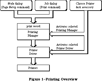 Figure 1–Printing Overview
The Printing Manager gives you a printing grafPort when you open a document for printing. You then print text and graphics by drawing into this port with QuickDraw, just as if you were drawing on the screen. The Printing Manager installs its own versions of QuickDraw’s low-level drawing routines in the printing grafPort, causing your higher-level QuickDraw calls to drive the printer instead of drawing on the screen.
Warning: You should not try to do your own customization of QuickDraw
routines in the printing grafPort unless you’re sure of what
you’re doing.
The Printing Manager has been enhanced and made easier to use through these changes:
• Its code has been moved from a linked file into the 256K ROM.
• New low-level printer control calls have been added, in the form
of new predefined parameter constants for PrCtlCall.
• A generic procedure called PrGeneral now lets your application
perform several advanced printer configuration tasks.
_______________________________________________________________________________
»PRINT RECORDS AND DIALOGS
_______________________________________________________________________________
To format and print a document, your application must know the following:
• the dimensions of the printable area of the page
• if the application must calculate the margins, the size of the physical
sheet of paper and the printer’s vertical and horizontal resolution
• which printing method is being used (draft or spool, explained below)
This information is contained in a data structure called a print record. The Printing Manager fills in the entire print record for you. Information that the user can specify is set through two standard dialogs.
The style dialog should be presented when the user selects the application’s Page Setup command from the File menu. It lets the user specify any options that affect the page dimensions, that is, the information you need for formatting the document to match the printer. Figure 2 shows the standard style dialog for the Imagewriter printer.
Figure 1–Printing Overview
The Printing Manager gives you a printing grafPort when you open a document for printing. You then print text and graphics by drawing into this port with QuickDraw, just as if you were drawing on the screen. The Printing Manager installs its own versions of QuickDraw’s low-level drawing routines in the printing grafPort, causing your higher-level QuickDraw calls to drive the printer instead of drawing on the screen.
Warning: You should not try to do your own customization of QuickDraw
routines in the printing grafPort unless you’re sure of what
you’re doing.
The Printing Manager has been enhanced and made easier to use through these changes:
• Its code has been moved from a linked file into the 256K ROM.
• New low-level printer control calls have been added, in the form
of new predefined parameter constants for PrCtlCall.
• A generic procedure called PrGeneral now lets your application
perform several advanced printer configuration tasks.
_______________________________________________________________________________
»PRINT RECORDS AND DIALOGS
_______________________________________________________________________________
To format and print a document, your application must know the following:
• the dimensions of the printable area of the page
• if the application must calculate the margins, the size of the physical
sheet of paper and the printer’s vertical and horizontal resolution
• which printing method is being used (draft or spool, explained below)
This information is contained in a data structure called a print record. The Printing Manager fills in the entire print record for you. Information that the user can specify is set through two standard dialogs.
The style dialog should be presented when the user selects the application’s Page Setup command from the File menu. It lets the user specify any options that affect the page dimensions, that is, the information you need for formatting the document to match the printer. Figure 2 shows the standard style dialog for the Imagewriter printer.
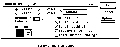 Figure 2–The Style Dialog
The job dialog should be presented when the user chooses to start printing with the Print command. It requests information about how to print the document this time, such as the print quality (for printers that offer a choice of resolutions), the type of paper feed (such as fanfold or cut-sheet), the range of pages to print, and the number of copies. Figure 3 shows the standard job dialog for the Imagewriter.
Figure 2–The Style Dialog
The job dialog should be presented when the user chooses to start printing with the Print command. It requests information about how to print the document this time, such as the print quality (for printers that offer a choice of resolutions), the type of paper feed (such as fanfold or cut-sheet), the range of pages to print, and the number of copies. Figure 3 shows the standard job dialog for the Imagewriter.
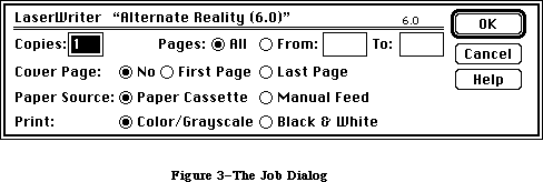 Figure 3–The Job Dialog
Note: The dialogs shown in Figures 2 and 3 are examples only; the
actual content of these dialogs is customized for each printer.
Print records are referred to by handles. Their structure is as follows:
TYPE THPrint = ^TPPrint;
TPPrint = ^TPrint;
TPrint = RECORD
iPrVersion: INTEGER; {Printing Manager version}
prInfo: TPrInfo; {printer information subrecord}
rPaper: Rect; {paper rectangle}
prStl: TPrStl; {additional device information}
prInfoPT: TPrInfo; {used internally}
prXInfo: TPrXInfo; {additional device information}
prJob: TPrJob; {job subrecord}
printX: ARRAY[1..19] OF INTEGER {not used}
END;
Warning: Your application should not change the data in the print record—be
sure to use the standard dialogs for setting this information. The
only fields you’ll need to set directly are some containing optional
information in the job subrecord (explained below). Attempting to set
other values directly in the print record can produce unexpected
results.
IPrVersion identifies the version of the Printing Manager that initialized this print record. If you try to use a print record that’s invalid for the current version of the Printing Manager or for the currently installed printer, the Printing Manager will correct the record by filling it with default values.
The other fields of the print record are discussed in separate sections below.
Note: Whenever you save a document, you should write an appropriate print
record in the document’s resource file. This lets the document
“remember” its own printing parameters for use the next time it’s
printed.
_______________________________________________________________________________
»The Printer Information Subrecord
The printer information subrecord (field prInfo of the print record) gives you the information needed for page composition. It’s defined as follows:
TYPE TPrInfo = RECORD
iDev: INTEGER; {used internally}
iVRes: INTEGER; {vertical resolution of printer}
iHRes: INTEGER; {horizontal resolution of printer}
rPage: Rect {page rectangle}
END;
RPage is the page rectangle, representing the boundaries of the printable page: The printing grafPort’s boundary rectangle, portRect, and clipRgn are set to this rectangle. Its top left corner always has coordinates (0,0); the coordinates of the bottom right corner give the maximum page height and width attainable on the given printer, in dots. Typically these are slightly less than the physical dimensions of the paper, because of the printer’s mechanical limitations. RPage is set as a result of the style dialog.
The rPage rectangle is inside the paper rectangle, specified by the rPaper field of the print record. RPaper gives the physical paper size, defined in the same coordinate system as rPage (see Figure 4). Thus the top left coordinates of the paper rectangle are typically negative and its bottom right coordinates are greater than those of the page rectangle.
IVRes and iHRes give the printer’s vertical and horizontal resolution in dots per inch. Thus, if you divide the width of rPage by iHRes, you get the width of the page rectangle in inches.
_______________________________________________________________________________
»The Job Subrecord
The job subrecord (field prJob of the print record) contains information about a particular printing job. Its contents are set as a result of the job dialog.
Figure 3–The Job Dialog
Note: The dialogs shown in Figures 2 and 3 are examples only; the
actual content of these dialogs is customized for each printer.
Print records are referred to by handles. Their structure is as follows:
TYPE THPrint = ^TPPrint;
TPPrint = ^TPrint;
TPrint = RECORD
iPrVersion: INTEGER; {Printing Manager version}
prInfo: TPrInfo; {printer information subrecord}
rPaper: Rect; {paper rectangle}
prStl: TPrStl; {additional device information}
prInfoPT: TPrInfo; {used internally}
prXInfo: TPrXInfo; {additional device information}
prJob: TPrJob; {job subrecord}
printX: ARRAY[1..19] OF INTEGER {not used}
END;
Warning: Your application should not change the data in the print record—be
sure to use the standard dialogs for setting this information. The
only fields you’ll need to set directly are some containing optional
information in the job subrecord (explained below). Attempting to set
other values directly in the print record can produce unexpected
results.
IPrVersion identifies the version of the Printing Manager that initialized this print record. If you try to use a print record that’s invalid for the current version of the Printing Manager or for the currently installed printer, the Printing Manager will correct the record by filling it with default values.
The other fields of the print record are discussed in separate sections below.
Note: Whenever you save a document, you should write an appropriate print
record in the document’s resource file. This lets the document
“remember” its own printing parameters for use the next time it’s
printed.
_______________________________________________________________________________
»The Printer Information Subrecord
The printer information subrecord (field prInfo of the print record) gives you the information needed for page composition. It’s defined as follows:
TYPE TPrInfo = RECORD
iDev: INTEGER; {used internally}
iVRes: INTEGER; {vertical resolution of printer}
iHRes: INTEGER; {horizontal resolution of printer}
rPage: Rect {page rectangle}
END;
RPage is the page rectangle, representing the boundaries of the printable page: The printing grafPort’s boundary rectangle, portRect, and clipRgn are set to this rectangle. Its top left corner always has coordinates (0,0); the coordinates of the bottom right corner give the maximum page height and width attainable on the given printer, in dots. Typically these are slightly less than the physical dimensions of the paper, because of the printer’s mechanical limitations. RPage is set as a result of the style dialog.
The rPage rectangle is inside the paper rectangle, specified by the rPaper field of the print record. RPaper gives the physical paper size, defined in the same coordinate system as rPage (see Figure 4). Thus the top left coordinates of the paper rectangle are typically negative and its bottom right coordinates are greater than those of the page rectangle.
IVRes and iHRes give the printer’s vertical and horizontal resolution in dots per inch. Thus, if you divide the width of rPage by iHRes, you get the width of the page rectangle in inches.
_______________________________________________________________________________
»The Job Subrecord
The job subrecord (field prJob of the print record) contains information about a particular printing job. Its contents are set as a result of the job dialog.
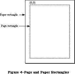 Figure 4–Page and Paper Rectangles
The job subrecord is defined as follows:
TYPE TPrJob = RECORD
iFstPage: INTEGER; {first page to print}
iLstPage: INTEGER; {last page to print}
iCopies: INTEGER; {number of copies}
bJDocLoop: SignedByte; {printing method}
fFromUsr: BOOLEAN; {used internally}
pIdleProc: ProcPtr; {background procedure}
pFileName: StringPtr; {spool file name}
iFileVol: INTEGER; {spool file volume reference number}
bFileVers: SignedByte; {spool file version number}
bJobX: SignedByte {used internally}
END;
BJDocLoop designates the printing method that the Printing Manager will use. It will be one of the following predefined constants:
CONST bDraftLoop = 0; {draft printing}
bSpoolLoop = 1; {spool printing}
Draft printing means that the document will be printed immediately. Spool printing means that printing may be deferred: The Printing Manager writes out a representation of the document’s printed image to a disk file (or possibly to memory); this information is then converted into a bit image and printed. For details about the printing methods, see the “Methods of Printing” section below. The Printing Manager sets the bJDocLoop field; your application should not change it.
IFstPage and iLstPage designate the first and last pages to be printed. These page numbers are relative to the first page counted by the Printing Manager. The Printing Manager knows nothing about any page numbering placed by an application within a document.
ICopies is the number of copies to print. The Printing Manager automatically handles multiple copies for spool printing or for printing on the LaserWriter. Your application only needs this number for draft printing on the Imagewriter.
PIdleProc is a pointer to the background procedure (explained below) for this printing operation. In a newly initialized print record this field is set to NIL, designating the default background procedure, which just polls the keyboard and cancels further printing if the user types Command-period. You can install a background procedure of your own by storing a pointer to your procedure directly into the pIdleProc field.
For spool printing, your application may optionally provide a spool file name, volume reference number, and version number (described in the File Manager chapter):
• PFileName is the name of the spool file. This field is initialized to
NIL, and generally not changed by the application. NIL denotes the
default file name (normally 'Print File') stored in the printer resource
file.
• IFileVol is the volume reference number of the spool file. This field
is initialized to 0, representing the default volume. You can use the
File Manager function SetVol to change the default volume, or you can
override the default setting by storing directly into this field.
• BFileVers is the version number of the spool file, initialized to 0.
_______________________________________________________________________________
»Additional Device Information
The prStl and prXInfo fields of the print record provide device information that your application may need to refer to.
The prStl field of the print record is defined as follows:
TYPE TPrStl = RECORD
wDev: INTEGER; {high byte specifies device}
{more fields for internal use}
END;
The high-order byte of the wDev field indicates which printer is currently selected. A value of 0 indicates the Macintosh screen; other values are reserved for future use. The low-order byte of wDev is used internally.
The prXInfo field of the print record is defined as follows:
TYPE TPrXInfo = RECORD
iRowBytes: INTEGER; {used internally}
iBandV: INTEGER; {used internally}
iBandH: INTEGER; {used internally}
iDevBytes: INTEGER; {size of buffer}
{more fields for internal use}
END;
IDevBytes is the number of bytes of memory required as a buffer for spool printing. (You need this information only if you choose to allocate your own buffer.)
_______________________________________________________________________________
»METHODS OF PRINTING
_______________________________________________________________________________
There are two basic methods of printing documents: draft and spool. The Printing Manager determines which method to use; the two methods are implemented in different ways for different printers.
In draft printing, your QuickDraw calls are converted directly into command codes the printer understands, which are then immediately used to drive the printer:
• On the Imagewriter, draft printing is used for printing quick,
low-quality drafts of text documents that are printed straight
down the page from top to bottom and left to right.
• On the LaserWriter, draft printing is used to obtain high-quality
output. (This typically requires 15K bytes of memory for your data
and printing code.)
Spool printing is a two-stage process. First, the Printing Manager writes out
(“spools”) a representation of your document’s printed image to a disk file or to memory. This information is then converted into a bit image and printed. On the Imagewriter, spool printing is used for standard or high-quality printing.
Spooling and printing are two separate stages because of memory considerations: Spooling a document takes only about 3K bytes of memory, but may require large portions of your application’s code and data in memory; printing the spooled document typically requires from 20K to 40K for the printing code, buffers, and fonts, but most of your application’s code and data are no longer needed. Normally you’ll make your printing code a separate program segment, so you can swap the rest of your code and data out of memory during printing and swap it back in after you’re finished (see the Segment Loader chapter).
Note: This chapter frequently refers to spool files, although there may be
cases when the document is spooled to memory. This difference will be
transparent to the application.
Note: The internal format of spool files is private to the Printing Manager
and may vary from one printer to another. This means that spool files
destined for one printer can’t be printed on another. In spool files for
the Imagewriter, each page is stored as a QuickDraw picture. It’s
envisioned that most other printers will use this same approach, but
there may be exceptions. Spool files can be identified by their file
type ('PFIL') and creator ('PSYS'). File type and creator are discussed
in the Finder Interface chapter.
_______________________________________________________________________________
»BACKGROUND PROCESSING
_______________________________________________________________________________
As mentioned above, the job subrecord includes a pointer, pIdleProc, to an optional background procedure to be run whenever the Printing Manager has directed output to the printer and is waiting for the printer to finish. The background procedure takes no parameters and returns no result; the Printing Manager simply runs it at every opportunity.
If you don’t designate a background procedure, the Printing Manager uses a default procedure for canceling printing: The default procedure just polls the keyboard and sets a Printing Manager error code if the user types Command-period. If you use this option, you should display a dialog box during printing to inform the user that the Command-period option is available.
Note: If you designate a background procedure, you must set pIdleProc after
presenting the dialogs, validating the print record, and initializing
the printing grafPort: The routines that perform these operations
reset pIdleProc to NIL.
Warning: If you write your own background procedure, you must be careful to
avoid a number of subtle concurrency problems that can arise. For
instance, if the background procedure uses QuickDraw, it must be
sure to restore the printing grafPort as the current port before
returning. It’s particularly important not to attempt any printing
from within the background procedure: The Printing Manager is not
reentrant! If you use a background procedure that runs your
application concurrently with printing, it should disable all menu
items having to do with printing, such as Page Setup and Print.
_______________________________________________________________________________
»USING THE PRINTING MANAGER
_______________________________________________________________________________
To use the Printing Manager, you must first initialize QuickDraw, the Font Manager, the Window Manager, the Menu Manager, TextEdit, and the Dialog Manager. The first Printing Manager routine to call is PrOpen; the last routine to call is PrClose.
Before you can print a document, you need a valid print record. You can either use an existing print record (for instance, one saved with a document), or initialize one by calling PrintDefault or PrValidate. If you use an existing print record, be sure to call PrValidate to make sure it’s valid for the current version of the Printing Manager and for the currently installed printer. To create a new print record, you must first create a handle to it with the Memory Manager function NewHandle, as follows:
prRecHdl := THPrint(NewHandle(SIZEOF(TPrint)))
Print record information is obtained via the style and job dialogs:
• Call PrStlDialog when the user chooses the Page Setup commmand, to get
the page dimensions. From the rPage field of the printer information
subrecord, you can then determine where page breaks will be in the
document. You can show rulers and margins correctly by using the
information in the iVRes, iHRes, and rPaper fields.
• Call PrJobDialog when the user chooses the Print commmand, to get the
specific information about that printing job, such as the page range and
number of copies.
You can apply the results of one job dialog to several documents (when printing from the Finder, for example) by calling PrJobMerge.
After getting the job information, you should immediately print the document.
_______________________________________________________________________________
»The Printing Loop
To print a document, you call the following procedures:
1. PrOpenDoc, which returns a printing grafPort that’s set up for draft
or spool printing (depending on the bJDocLoop field of the job subrecord)
2. PrOpenPage, which starts each new page (reinitializing the grafPort)
3. QuickDraw routines, for drawing the page in the printing grafPort
created by PrOpenDoc
4. PrClosePage, which terminates the page
5. PrCloseDoc, at the end of the entire document, to close the printing
grafPort
Each page is either printed immediately (draft printing) or written to the disk or to memory (spool printing). You should test to see whether spooling was done, and if so, print the spooled document: First, swap as much of your program out of memory as you can (see the Segment Loader chapter), and then call PrPicFile.
It’s a good idea to call PrError after each Printing Manager call, to check for any errors. To cancel a printing operation in progress, use PrSetError. If an error occurs and you cancel printing (or if the user aborts printing), be sure to exit normally from the printing loop so that all files are closed properly; that is, be sure that every PrOpenPage is matched by a PrClosePage and PrOpenDoc is matched by PrCloseDoc.
To sum up, your application’s printing loop will typically use the following basic format for printing:
myPrPort := PrOpenDoc(prRecHdl,NIL,NIL); {open printing grafPort}
FOR pg := 1 TO myPgCount DO {page loop: ALL pages of document}
IF PrError = noErr
THEN
BEGIN
PrOpenPage(myPrPort,NIL); {start new page}
IF PrError = noErr
THEN MyDrawingProc(pg); {draw page with QuickDraw}
PrClosePage(myPrPort); {end current page}
END;
PrCloseDoc(myPrPort); {close printing grafPort}
IF prRecHdl^^.prJob.bJDocLoop = bSpoolLoop AND PrError = noErr
THEN
BEGIN
MySwapOutProc; {swap out code and data}
PrPicFile(prRecHdl,NIL,NIL,NIL,myStRec); {print spooled document}
END;
IF PrError <> noErr THEN MyPrErrAlertProc {report any errors}
Note an important assumption in this example: The MyDrawingProc procedure must be able to determine the page boundaries without stepping through each page of the document.
Although spool printing may not be supported on all printers, you must be sure to include PrPicFile in your printing code, as shown above. The application should make no assumptions about the printing method.
Note: The maximum number of pages in a spool file is defined by the
following constant:
CONST iPFMaxPgs = 128;
If you need to print more than 128 pages at one time, just repeat the printing loop (without calling PrValidate, PrStlDialog, or PrJobDialog).
_______________________________________________________________________________
»Printing a Specified Range of Pages
The above example loops through every page of the document, regardless of which pages the user has selected; the Printing Manager draws each page but actually prints only the pages from iFstPage to iLstPage.
If you know the page boundaries in the document, it’s much faster to loop through only the specified pages. You can do this by saving the values of iFstPage and iLstPage and then changing these fields in the print record: For example, to print pages 20 to 25, you would set iFstPage to 1 and iLstPage to 6 (or greater) and then begin printing at your page 20. You could implement this for all cases as follows:
myFirst := prRecHdl^^.prJob.iFstPage; {save requested page numbers}
myLast := prRecHdl^^.prJob.iLstPage;
prRecHdl^^.prJob.iFstPage := 1; {print “all” pages in loop}
prRecHdl^^.prJob.iLstPage := 9999;
FOR pg := myFirst TO myLast DO {page loop: requested pages only}
. . . {print as in first example}
Remember that iFstPage and iLstPage are relative to the first page counted by the Printing Manager. The Printing Manager counts one page each time PrOpenPage is called; the count begins at 1.
_______________________________________________________________________________
»Using QuickDraw for Printing
When drawing to the printing grafPort, you should note the following:
• With each new page, you get a completely reinitialized grafPort, so
you’ll need to reset font information and other grafPort characteristics
as desired.
• Don’t make calls that don’t do anything on the printer. For example,
erase operations are quite time-consuming and normally aren’t needed
on the printer.
• Don’t use clipping to select text to be printed. There are a number of
subtle differences between how text appears on the screen and how it
appears on the printer; you can’t count on knowing the exact dimensions
of the rectangle occupied by the text.
• Don’t use fixed-width fonts to align columns. Since spacing gets
adjusted on the printer, you should explicitly move the pen to where
you want it.
For printing to the LaserWriter, you’ll need to observe the following limitations:
• Regions aren’t supported; try to simulate them with polygons.
• Clipping regions should be limited to rectangles.
• “Invert” routines aren’t supported.
• Copy is the only transfer mode supported for all objects except text
and bit images. For text, Bic is also supported. For bit images, the
only transfer mode not supported is Xor.
• Using SetOrigin within the printing loop is supported, but you should
refer to Technical Note #183 for implementation details.
X-Ref: Technical Note #183
For more information about optimizing your printing code for the LaserWriter, see the Apple LaserWriter Reference.
_______________________________________________________________________________
»Printing From the Finder
The Macintosh user can choose to print from the Finder as well as from an application. Your application should support both alternatives.
To print a document from the Finder, the user selects the document’s icon and chooses the Print command from the File menu. Note that the user can select more than one document, or even a document and an application, which means that the application must verify that it can print the document before proceeding. When the Print command is chosen, the Finder starts up the application, and passes information to it indicating that the document is to be printed rather than opened (see the Segment Loader chapter). Your application should then do the following, preferably without going through its entire startup sequence:
1. Call PrJobDialog. (If the user selected more than one document, you
can use PrJobMerge to apply one job dialog to all of the documents.)
2. Print the document(s).
_______________________________________________________________________________
»PRINTING MANAGER ROUTINES
_______________________________________________________________________________
This section describes the high-level Printing Manager routines; low-level routines are described below in the section “The Printer Driver”.
Assembly-language note: There are no trap macros for these routines. To
print from assembly language, call these Pascal
routines from your program.
_______________________________________________________________________________
»Initialization and Termination
PROCEDURE PrOpen; [Not in ROM]
PrOpen prepares the Printing Manager for use. It opens the Printer Driver and the printer resource file. If either of these is missing, or if the printer resource file isn’t properly formed, PrOpen will do nothing, and PrError will return a Resource Manager result code.
PROCEDURE PrClose; [Not in ROM]
PrClose releases the memory used by the Printing Manager. It closes the printer resource file, allowing the file’s resource map to be removed from memory. It doesn’t close the Printer Driver.
_______________________________________________________________________________
»Print Records and Dialogs
PROCEDURE PrintDefault (hPrint: THPrint); [Not in ROM]
PrintDefault fills the fields of the specified print record with default values that are stored in the printer resource file. HPrint is a handle to the record, which may be a new print record that you’ve just allocated with NewHandle or an existing one (from a document, for example).
FUNCTION PrValidate (hPrint: THPrint) : BOOLEAN; [Not in ROM]
PrValidate checks the contents of the specified print record for compatibility with the current version of the Printing Manager and with the currently installed printer. If the record is valid, the function returns FALSE (no change); if invalid, the record is adjusted to the default values stored in the printer resource file, and the function returns TRUE.
PrValidate also makes sure all the information in the print record is internally self-consistent and updates the print record as necessary. These changes do not affect the function’s Boolean result.
Warning: You should never call PrValidate (or PrStlDialog or PrJobDialog,
which call it) between pages of a document.
FUNCTION PrStlDialog (hPrint: THPrint) : BOOLEAN; [Not in ROM]
PrStlDialog conducts a style dialog with the user to determine the page dimensions and other information needed for page setup. The initial settings displayed in the dialog box are taken from the most recent print record. If the user confirms the dialog, the results of the dialog are saved in the specified print record, PrValidate is called, and the function returns TRUE. Otherwise, the print record is left unchanged and the function returns FALSE.
Note: If the print record was taken from a document, you should update its
contents in the document’s resource file if PrStlDialog returns TRUE.
This makes the results of the style dialog “stick” to the document.
FUNCTION PrJobDialog (hPrint: THPrint) : BOOLEAN; [Not in ROM]
PrJobDialog conducts a job dialog with the user to determine the print quality, range of pages to print, and so on. The initial settings displayed in the dialog box are taken from the printer resource file, where they were remembered from the previous job (with the exception of the page range, set to all, and the copies, set to 1).
If the user confirms the dialog, both the print record and the printer resource file are updated, PrValidate is called, and the function returns TRUE. Otherwise, the print record and printer resource file are left unchanged and the function returns FALSE.
Note: Since the job dialog is associated with the Print command, you should
proceed with the requested printing operation if PrJobDialog returns
TRUE.
PROCEDURE PrJobMerge (hPrintSrc,hPrintDst: THPrint); [Not in ROM]
PrJobMerge first calls PrValidate for each of the given print records. It then copies all of the information set as a result of a job dialog from hPrintSrc to hPrintDst. Finally, it makes sure that all the fields of hPrintDst are internally self-consistent.
PrJobMerge allows you to conduct a job dialog just once and then copy the job information to several print records, which means that you can print several documents with one dialog. This is useful when printing from the Finder.
_______________________________________________________________________________
»»Printing
FUNCTION PrOpenDoc (hPrint: THPrint; pPrPort: TPPrPort;
pIOBuf: Ptr) : TPPrPort; [Not in ROM]
PrOpenDoc initializes a printing grafPort for use in printing a document, makes it the current port, and returns a pointer to it.
HPrint is a handle to the print record for this printing operation; you should already have validated this print record.
Depending on the setting of the bJDocLoop field in the job subrecord, the printing grafPort will be set up for draft or spool printing. For spool printing, the spool file’s name, volume reference number, and version number are taken from the job subrecord.
PPrPort and pIOBuf are normally NIL. PPrPort is a pointer to the printing grafPort; if it’s NIL, PrOpenDoc allocates a new printing grafPort in the heap. Similarly, pIOBuf points to an area of memory to be used as an input/output buffer; if it’s NIL, PrOpenDoc uses the volume buffer for the spool file’s volume. If you allocate your own buffer, it must be 522 bytes long.
Note: These parameters are provided because the printing grafPort and
input/output buffer are both nonrelocatable objects; to avoid
fragmenting the heap, you may want to allocate them yourself.
You must balance every call to PrOpenDoc with a call to PrCloseDoc.
PROCEDURE PrOpenPage (pPrPort: TPPrPort; pPageFrame: TPRect); [Not in ROM]
PrOpenPage begins a new page. The page is printed only if it falls within the page range given in the job subrecord.
For spool printing, the pPageFrame parameter is used for scaling. It points to a rectangle to be used as the QuickDraw picture frame for this page:
TYPE TPRect = ^Rect;
When you print the spooled document, this rectangle will be scaled (with the QuickDraw procedure DrawPicture) to coincide with the rPage rectangle in the printer information subrecord. Unless you want the printout to be scaled, you should set pPageFrame to NIL—this uses the rPage rectangle as the picture frame, so that the page will be printed with no scaling.
Warning: Don’t call the QuickDraw function OpenPicture while a page is open
(after a call to PrOpenPage and before the following PrClosePage).
You can, however, call DrawPicture at any time.
Warning: The printing grafPort is completely reinitialized by PrOpenPage.
Therefore, you must set grafPort features such as the font and
font size for every page that you draw.
You must balance every call to PrOpenPage with a call to PrClosePage.
PROCEDURE PrClosePage (pPrPort: TPPrPort); [Not in ROM]
PrClosePage finishes the printing of the current page. It lets the Printing Manager know that you’re finished with this page, so that it can do whatever is required for the current printer and printing method.
PROCEDURE PrCloseDoc (pPrPort: TPPrPort); [Not in ROM]
PrCloseDoc closes the printing grafPort. For draft printing, PrCloseDoc ends the printing job. For spool printing, PrCloseDoc ends the spooling process: The spooled document must now be printed. Before printing it, call PrError to find out whether spooling succeeded; if it did, you should swap out as much code as possible and then call PrPicFile.
PROCEDURE PrPicFile (hPrint: THPrint; pPrPort: TPPrPort; pIOBuf: Ptr;
pDevBuf: Ptr; VAR prStatus: TPrStatus); [Not in ROM]
PrPicFile prints a spooled document. If spool printing is being used, your application should normally call PrPicFile after PrCloseDoc.
HPrint is a handle to the print record for this printing job. The spool file’s name, volume reference number, and version number are taken from the job subrecord of this print record. After printing is successfully completed, the Printing Manager deletes the spool file from the disk.
You’ll normally pass NIL for pPrPort, pIOBuf, and pDevBuf. PPrPort is a pointer to the printing grafPort for this operation; if it’s NIL, PrPicFile allocates a new printing grafPort in the heap. Similarly, pIOBuf points to an area of memory to be used as an input /output buffer for reading the spool file; if
it’s NIL, PrPicFile uses the volume buffer for the spool file’s volume. PDevBuf points to a device-dependent buffer; if NIL, PrPicFile allocates a buffer in the heap.
Note: If you provide your own storage for pDevBuf, it has to be big enough
to hold the number of bytes indicated by the iDevBytes field of the
PrXInfo subrecord.
Warning: Be sure not to pass, in pPrPort, a pointer to the same printing
grafPort you received from PrOpenDoc. If that port was allocated
by PrOpenDoc itself (that is, if the pPrPort parameter to PrOpenDoc
was NIL), then PrCloseDoc will have disposed of the port, making
your pointer to it invalid. Of course, if you earlier provided your
own storage to PrOpenDoc, there’s no reason you can’t use the same
storage again for PrPicFile.
The prStatus parameter is a printer status record that PrPicFile will use to report on its progress:
TYPE TPrStatus = RECORD
iTotPages: INTEGER; {number of pages in spool file}
iCurPage: INTEGER; {page being printed}
iTotCopies: INTEGER; {number of copies requested}
iCurCopy: INTEGER; {copy being printed}
iTotBands: INTEGER; {used internally}
iCurBand: INTEGER; {used internally}
fPgDirty: BOOLEAN; {TRUE if started printing page}
fImaging: BOOLEAN; {used internally}
hPrint: THPrint; {print record}
pPrPort: TPPrPort; {printing grafPort}
hPic: PicHandle {used internally}
END;
The fPgDirty field is TRUE if anything has already been printed on the current page, FALSE if not.
Your background procedure (if any) can use this record to monitor the state of the printing operation.
_______________________________________________________________________________
»Error Handling
FUNCTION PrError : INTEGER; [Not in ROM]
PrError returns the result code left by the last Printing Manager routine. Some possible result codes are:
CONST noErr = 0; {no error}
iPrSavPFil = —1; {saving print file}
controlErr = —17; {unimplemented control instruction}
iIOAbort = —27; {I/O error}
iMemFullErr = —108; {not enough room in heap zone}
iPrAbort = 128; {application or user requested abort}
{ The following result codes are LaserWriter-specific }
–4101; { Printer not found or closed }
–4100; { Connection just closed }
–4099; { Write request too big }
–4098; { Request already active }
–4097; { Bad connection refnum }
–4096; { No free CCBs (Connect Control Blocks) available }
–8133; { PostScript error occurred during transmission }
{ of data to printer. Most often caused by a bug }
{ in the PostScript code being downloaded. }
–8132; { Timeout occured. This error is returned when }
{ no data has been sent to the printer for 2 }
{ minutes. Usually caused by extremely long }
{ imaging times. }
ControlErr is returned by the Device Manager. Other Operating System or Toolbox result codes may also be returned; a list of all result codes is given in Appendix A.
Assembly-language note: The current result code is contained in the global
variable PrintErr.
PROCEDURE PrSetError (iErr: INTEGER); [Not in ROM]
PrSetError stores the specified value into the global variable where the Printing Manager keeps its result code. This procedure is used for canceling a printing operation in progress. To do this, call:
IF PrError <> noErr THEN PrSetError(iPrAbort)
Assembly-language note: You can achieve the same effect as PrSetError by
storing directly into the global variable PrintErr.
You shouldn’t, however, store into this variable
if it already contains a nonzero value.
_______________________________________________________________________________
»CALLING THE PRINTING MANAGER IN ROM
_______________________________________________________________________________
All the Printing Manager routines are now accessible through the single trap
_PrGlue, available in System file version 4.1 and later. To use trap calls with all System file versions, link your application to PRGlue, available in the MPW 2.0 file Interface.o.
Here are the Printing Manager trap calls as they appear in the Pascal interface:
PROCEDURE PrOpen;
PROCEDURE PrClose;
PROCEDURE PrintDefault (hPrint: THPrint);
FUNCTION PrValidate (hPrint: THPrint) : Boolean;
FUNCTION PrStlDialog (hPrint: THPrint) : Boolean;
FUNCTION PrJobDialog (hPrint: THPrint) : Boolean;
PROCEDURE PrJobMerge (hPrintSrc, hPrintDst: THPrint);
FUNCTION PrOpenDoc (hPrint: THPrint; pPrPort: TPPrPort;
pIOBuf: Ptr): TPPrPort;
PROCEDURE PrCloseDoc (pPrPort: TPPrPort);
PROCEDURE PrOpenPage (pPrPort: TPPrPort; pPageFrame: TPRect);
PROCEDURE PrClosePage (pPrPort: TPPrPort);
PROCEDURE PrPicFile (hPrint: THPrint; pPrPort: TPPrPort; pIOBuf: Ptr;
pDevBuf: Ptr; VAR PrStatus: TPrStatus);
FUNCTION PrError: Integer;
PROCEDURE PrSetError (iErr: Integer);
PROCEDURE PrDrvrOpen;
PROCEDURE PrDrvrClose;
PROCEDURE PrCtlCall (iWhichCtl: Integer; lParam1, lParam2, lParam3: LongInt);
FUNCTION PrDrvrDCE: Handle;
FUNCTION PrDrvrVers: Integer;
You can still call Printing Manager routines with the formats given in the previous section by using one of the following interface files:
• PrintTraps.p for Pascal
• PrintTraps.h for C
• PrintTraps.a for assembly language
Assembly-language note: You can invoke each of the Printing Manager routines
by pushing a longint called a routine selector on the
stack and then executing the _PrGlue trap ($A8FD).
The routine selectors are the following:
PrOpen EQU $C8000000
PrClose EQU $D0000000
PrintDefault EQU $20040480
PrValidate EQU $52040498
PrStlDialog EQU $2A040484
PrJobDialog EQU $32040488
PrJobMerge EQU $5804089C
PrOpenDoc EQU $04000C00
PrCloseDoc EQU $08000484
PrOpenPage EQU $10000808
PrClosePage EQU $1800040C
PrPicFile EQU $60051480
PrError EQU $BA000000
PrSetError EQU $C0000200
PrDrvrOpen EQU $80000000
PrDrvrClose EQU $88000000
PrCtlCall EQU $A0000E00
PrDrvrDCE EQU $94000000
PrDrvrVers EQU $9A000000
_______________________________________________________________________________
»PRGENERAL
_______________________________________________________________________________
The Printing Manager has been expanded to include a new procedure called PrGeneral. It provides advanced, special-purpose features, intended to solve specific problems for those applications that need them. You can use PrGeneral with version 2.5 and later of the ImageWriter driver and version 4.0 and later of the LaserWriter driver. The Pascal declaration of PrGeneral is
PROCEDURE PrGeneral (pData: Ptr);
The pData parameter is a pointer to a data block. The structure of the data block is declared as follows:
TGnlData = RECORD
{1st 8 bytes are common for all PrGeneral calls);
iOpCode: Integer; {input}
iError: Integer; {output}
lReserved: LongInt; {reserved for future use}
{more fields here, depending on particular call}
END;
The first field in the TGnlData record is a 2-byte opcode, iOpCode, which acts somewhat like a routine selector. The currently available opcodes are these:
• GetRslData (get resolution data): iOpCode = 4
• SetRsl (set resolution): iOpCode = 5
• DraftBits (bitmaps in draft mode): iOpCode = 6
• NoDraftBits (no bitmaps in draft mode): iOpCode = 7
• GetRotn (get rotation): iOpCode = 8
GetRslData and SetRsl allow the application to find out what physical resolutions the printer supports, and then specify a supported resolution. DraftBits and noDraftBits invoke a new feature of the ImageWriter, allowing bitmaps (imaged via CopyBits) to be printed in draft mode. GetRotn lets an application know whether landscape orientation has been selected. These routines are described in the next sections.
The second field in the TGnlData record is the error result, iError, returned by the print code. This error only reflects error conditions that occur during the PrGeneral call. For example, if you use an opcode that isn’t implemented in a particular printer driver then you will get an OpNotImpl error. Here are the error codes:
CONST
NoErr = 0; {no error}
NoSuchRsl = 1; {the resolution you chose isn't available}
OpNotImpl = 2; {the driver doesn't support this opcode}
After calling PrGeneral you should always check PrError. If NoErr is returned, then you can proceed. If ResNotFound is returned, then the current printer driver doesn’t support PrGeneral and you should proceed appropriately.
IError is followed by a four byte reserved field. The contents of the rest of the data block depends on the opcode that the application uses.
_______________________________________________________________________________
»GetRslData
GetRslData (iOpCode = 4) returns a record that lets the application know what resolutions are supported by the current printer. The application can then use SetRsl to tell the printer driver which one it will use. These calls introduce a good deal of complexity into your application’s code, and should be used only when necessary.
This is the format of the input data block for the GetRslData call:
TRslRg = RECORD {used in TGetRslBlk}
iMin: Integer; {0 if printer supports only discrete resolutions}
iMax: Integer; {0 if printer supports only discrete resolutions}
END;
TRslRec = RECORD {used in TGetRslBlk}
iXRsl: Integer; {a discrete, physical X resolution}
iYRsl: Integer; {a discrete, physical Y resolution}
END;
TGetRslBlk = RECORD {data block for GetRslData call}
iOpCode: Integer; {input; = getRslDataOp}
iError: Integer; {output}
lReserved: LongInt; {reserved for future use}
iRgType: Integer; {output; version number}
XRslRg: TRslRg; {output; range of X resolutions}
YRslRg: TRslRg; {output; range of Y resolutions}
iRslRecCnt: Integer; {output; how many RslRecs follow}
rgRslRec: ARRAY[1..27] OF TRslRec; {output; number filled }
{ depends on printer type}
END;
The iRgType field is much like a version number; it determines the interpretation of the data that follows. An iRgType value of 1 applies both to the LaserWriter and to the ImageWriter.
For variable-resolution printers like the LaserWriter, the resolution range fields XRslRg and YRslRg express the ranges of values to which the X and Y resolutions can be set. For discrete-resolution printers like the ImageWriter, the values in the resolution range fields are zero.
Note: In general, X and Y in these records are the horizontal and vertical
directions of the printer, not the document. In “landscape”
orientation, X is horizontal on the printer but vertical on the document.
After the resolution range information there is a word which gives the number of resolution records that contain information. These records indicate the physical resolutions at which the printer can actually print dots. Each resolution record gives an X value and a Y value.
When you call PrGeneral, use the following data block:
Figure 4–Page and Paper Rectangles
The job subrecord is defined as follows:
TYPE TPrJob = RECORD
iFstPage: INTEGER; {first page to print}
iLstPage: INTEGER; {last page to print}
iCopies: INTEGER; {number of copies}
bJDocLoop: SignedByte; {printing method}
fFromUsr: BOOLEAN; {used internally}
pIdleProc: ProcPtr; {background procedure}
pFileName: StringPtr; {spool file name}
iFileVol: INTEGER; {spool file volume reference number}
bFileVers: SignedByte; {spool file version number}
bJobX: SignedByte {used internally}
END;
BJDocLoop designates the printing method that the Printing Manager will use. It will be one of the following predefined constants:
CONST bDraftLoop = 0; {draft printing}
bSpoolLoop = 1; {spool printing}
Draft printing means that the document will be printed immediately. Spool printing means that printing may be deferred: The Printing Manager writes out a representation of the document’s printed image to a disk file (or possibly to memory); this information is then converted into a bit image and printed. For details about the printing methods, see the “Methods of Printing” section below. The Printing Manager sets the bJDocLoop field; your application should not change it.
IFstPage and iLstPage designate the first and last pages to be printed. These page numbers are relative to the first page counted by the Printing Manager. The Printing Manager knows nothing about any page numbering placed by an application within a document.
ICopies is the number of copies to print. The Printing Manager automatically handles multiple copies for spool printing or for printing on the LaserWriter. Your application only needs this number for draft printing on the Imagewriter.
PIdleProc is a pointer to the background procedure (explained below) for this printing operation. In a newly initialized print record this field is set to NIL, designating the default background procedure, which just polls the keyboard and cancels further printing if the user types Command-period. You can install a background procedure of your own by storing a pointer to your procedure directly into the pIdleProc field.
For spool printing, your application may optionally provide a spool file name, volume reference number, and version number (described in the File Manager chapter):
• PFileName is the name of the spool file. This field is initialized to
NIL, and generally not changed by the application. NIL denotes the
default file name (normally 'Print File') stored in the printer resource
file.
• IFileVol is the volume reference number of the spool file. This field
is initialized to 0, representing the default volume. You can use the
File Manager function SetVol to change the default volume, or you can
override the default setting by storing directly into this field.
• BFileVers is the version number of the spool file, initialized to 0.
_______________________________________________________________________________
»Additional Device Information
The prStl and prXInfo fields of the print record provide device information that your application may need to refer to.
The prStl field of the print record is defined as follows:
TYPE TPrStl = RECORD
wDev: INTEGER; {high byte specifies device}
{more fields for internal use}
END;
The high-order byte of the wDev field indicates which printer is currently selected. A value of 0 indicates the Macintosh screen; other values are reserved for future use. The low-order byte of wDev is used internally.
The prXInfo field of the print record is defined as follows:
TYPE TPrXInfo = RECORD
iRowBytes: INTEGER; {used internally}
iBandV: INTEGER; {used internally}
iBandH: INTEGER; {used internally}
iDevBytes: INTEGER; {size of buffer}
{more fields for internal use}
END;
IDevBytes is the number of bytes of memory required as a buffer for spool printing. (You need this information only if you choose to allocate your own buffer.)
_______________________________________________________________________________
»METHODS OF PRINTING
_______________________________________________________________________________
There are two basic methods of printing documents: draft and spool. The Printing Manager determines which method to use; the two methods are implemented in different ways for different printers.
In draft printing, your QuickDraw calls are converted directly into command codes the printer understands, which are then immediately used to drive the printer:
• On the Imagewriter, draft printing is used for printing quick,
low-quality drafts of text documents that are printed straight
down the page from top to bottom and left to right.
• On the LaserWriter, draft printing is used to obtain high-quality
output. (This typically requires 15K bytes of memory for your data
and printing code.)
Spool printing is a two-stage process. First, the Printing Manager writes out
(“spools”) a representation of your document’s printed image to a disk file or to memory. This information is then converted into a bit image and printed. On the Imagewriter, spool printing is used for standard or high-quality printing.
Spooling and printing are two separate stages because of memory considerations: Spooling a document takes only about 3K bytes of memory, but may require large portions of your application’s code and data in memory; printing the spooled document typically requires from 20K to 40K for the printing code, buffers, and fonts, but most of your application’s code and data are no longer needed. Normally you’ll make your printing code a separate program segment, so you can swap the rest of your code and data out of memory during printing and swap it back in after you’re finished (see the Segment Loader chapter).
Note: This chapter frequently refers to spool files, although there may be
cases when the document is spooled to memory. This difference will be
transparent to the application.
Note: The internal format of spool files is private to the Printing Manager
and may vary from one printer to another. This means that spool files
destined for one printer can’t be printed on another. In spool files for
the Imagewriter, each page is stored as a QuickDraw picture. It’s
envisioned that most other printers will use this same approach, but
there may be exceptions. Spool files can be identified by their file
type ('PFIL') and creator ('PSYS'). File type and creator are discussed
in the Finder Interface chapter.
_______________________________________________________________________________
»BACKGROUND PROCESSING
_______________________________________________________________________________
As mentioned above, the job subrecord includes a pointer, pIdleProc, to an optional background procedure to be run whenever the Printing Manager has directed output to the printer and is waiting for the printer to finish. The background procedure takes no parameters and returns no result; the Printing Manager simply runs it at every opportunity.
If you don’t designate a background procedure, the Printing Manager uses a default procedure for canceling printing: The default procedure just polls the keyboard and sets a Printing Manager error code if the user types Command-period. If you use this option, you should display a dialog box during printing to inform the user that the Command-period option is available.
Note: If you designate a background procedure, you must set pIdleProc after
presenting the dialogs, validating the print record, and initializing
the printing grafPort: The routines that perform these operations
reset pIdleProc to NIL.
Warning: If you write your own background procedure, you must be careful to
avoid a number of subtle concurrency problems that can arise. For
instance, if the background procedure uses QuickDraw, it must be
sure to restore the printing grafPort as the current port before
returning. It’s particularly important not to attempt any printing
from within the background procedure: The Printing Manager is not
reentrant! If you use a background procedure that runs your
application concurrently with printing, it should disable all menu
items having to do with printing, such as Page Setup and Print.
_______________________________________________________________________________
»USING THE PRINTING MANAGER
_______________________________________________________________________________
To use the Printing Manager, you must first initialize QuickDraw, the Font Manager, the Window Manager, the Menu Manager, TextEdit, and the Dialog Manager. The first Printing Manager routine to call is PrOpen; the last routine to call is PrClose.
Before you can print a document, you need a valid print record. You can either use an existing print record (for instance, one saved with a document), or initialize one by calling PrintDefault or PrValidate. If you use an existing print record, be sure to call PrValidate to make sure it’s valid for the current version of the Printing Manager and for the currently installed printer. To create a new print record, you must first create a handle to it with the Memory Manager function NewHandle, as follows:
prRecHdl := THPrint(NewHandle(SIZEOF(TPrint)))
Print record information is obtained via the style and job dialogs:
• Call PrStlDialog when the user chooses the Page Setup commmand, to get
the page dimensions. From the rPage field of the printer information
subrecord, you can then determine where page breaks will be in the
document. You can show rulers and margins correctly by using the
information in the iVRes, iHRes, and rPaper fields.
• Call PrJobDialog when the user chooses the Print commmand, to get the
specific information about that printing job, such as the page range and
number of copies.
You can apply the results of one job dialog to several documents (when printing from the Finder, for example) by calling PrJobMerge.
After getting the job information, you should immediately print the document.
_______________________________________________________________________________
»The Printing Loop
To print a document, you call the following procedures:
1. PrOpenDoc, which returns a printing grafPort that’s set up for draft
or spool printing (depending on the bJDocLoop field of the job subrecord)
2. PrOpenPage, which starts each new page (reinitializing the grafPort)
3. QuickDraw routines, for drawing the page in the printing grafPort
created by PrOpenDoc
4. PrClosePage, which terminates the page
5. PrCloseDoc, at the end of the entire document, to close the printing
grafPort
Each page is either printed immediately (draft printing) or written to the disk or to memory (spool printing). You should test to see whether spooling was done, and if so, print the spooled document: First, swap as much of your program out of memory as you can (see the Segment Loader chapter), and then call PrPicFile.
It’s a good idea to call PrError after each Printing Manager call, to check for any errors. To cancel a printing operation in progress, use PrSetError. If an error occurs and you cancel printing (or if the user aborts printing), be sure to exit normally from the printing loop so that all files are closed properly; that is, be sure that every PrOpenPage is matched by a PrClosePage and PrOpenDoc is matched by PrCloseDoc.
To sum up, your application’s printing loop will typically use the following basic format for printing:
myPrPort := PrOpenDoc(prRecHdl,NIL,NIL); {open printing grafPort}
FOR pg := 1 TO myPgCount DO {page loop: ALL pages of document}
IF PrError = noErr
THEN
BEGIN
PrOpenPage(myPrPort,NIL); {start new page}
IF PrError = noErr
THEN MyDrawingProc(pg); {draw page with QuickDraw}
PrClosePage(myPrPort); {end current page}
END;
PrCloseDoc(myPrPort); {close printing grafPort}
IF prRecHdl^^.prJob.bJDocLoop = bSpoolLoop AND PrError = noErr
THEN
BEGIN
MySwapOutProc; {swap out code and data}
PrPicFile(prRecHdl,NIL,NIL,NIL,myStRec); {print spooled document}
END;
IF PrError <> noErr THEN MyPrErrAlertProc {report any errors}
Note an important assumption in this example: The MyDrawingProc procedure must be able to determine the page boundaries without stepping through each page of the document.
Although spool printing may not be supported on all printers, you must be sure to include PrPicFile in your printing code, as shown above. The application should make no assumptions about the printing method.
Note: The maximum number of pages in a spool file is defined by the
following constant:
CONST iPFMaxPgs = 128;
If you need to print more than 128 pages at one time, just repeat the printing loop (without calling PrValidate, PrStlDialog, or PrJobDialog).
_______________________________________________________________________________
»Printing a Specified Range of Pages
The above example loops through every page of the document, regardless of which pages the user has selected; the Printing Manager draws each page but actually prints only the pages from iFstPage to iLstPage.
If you know the page boundaries in the document, it’s much faster to loop through only the specified pages. You can do this by saving the values of iFstPage and iLstPage and then changing these fields in the print record: For example, to print pages 20 to 25, you would set iFstPage to 1 and iLstPage to 6 (or greater) and then begin printing at your page 20. You could implement this for all cases as follows:
myFirst := prRecHdl^^.prJob.iFstPage; {save requested page numbers}
myLast := prRecHdl^^.prJob.iLstPage;
prRecHdl^^.prJob.iFstPage := 1; {print “all” pages in loop}
prRecHdl^^.prJob.iLstPage := 9999;
FOR pg := myFirst TO myLast DO {page loop: requested pages only}
. . . {print as in first example}
Remember that iFstPage and iLstPage are relative to the first page counted by the Printing Manager. The Printing Manager counts one page each time PrOpenPage is called; the count begins at 1.
_______________________________________________________________________________
»Using QuickDraw for Printing
When drawing to the printing grafPort, you should note the following:
• With each new page, you get a completely reinitialized grafPort, so
you’ll need to reset font information and other grafPort characteristics
as desired.
• Don’t make calls that don’t do anything on the printer. For example,
erase operations are quite time-consuming and normally aren’t needed
on the printer.
• Don’t use clipping to select text to be printed. There are a number of
subtle differences between how text appears on the screen and how it
appears on the printer; you can’t count on knowing the exact dimensions
of the rectangle occupied by the text.
• Don’t use fixed-width fonts to align columns. Since spacing gets
adjusted on the printer, you should explicitly move the pen to where
you want it.
For printing to the LaserWriter, you’ll need to observe the following limitations:
• Regions aren’t supported; try to simulate them with polygons.
• Clipping regions should be limited to rectangles.
• “Invert” routines aren’t supported.
• Copy is the only transfer mode supported for all objects except text
and bit images. For text, Bic is also supported. For bit images, the
only transfer mode not supported is Xor.
• Using SetOrigin within the printing loop is supported, but you should
refer to Technical Note #183 for implementation details.
X-Ref: Technical Note #183
For more information about optimizing your printing code for the LaserWriter, see the Apple LaserWriter Reference.
_______________________________________________________________________________
»Printing From the Finder
The Macintosh user can choose to print from the Finder as well as from an application. Your application should support both alternatives.
To print a document from the Finder, the user selects the document’s icon and chooses the Print command from the File menu. Note that the user can select more than one document, or even a document and an application, which means that the application must verify that it can print the document before proceeding. When the Print command is chosen, the Finder starts up the application, and passes information to it indicating that the document is to be printed rather than opened (see the Segment Loader chapter). Your application should then do the following, preferably without going through its entire startup sequence:
1. Call PrJobDialog. (If the user selected more than one document, you
can use PrJobMerge to apply one job dialog to all of the documents.)
2. Print the document(s).
_______________________________________________________________________________
»PRINTING MANAGER ROUTINES
_______________________________________________________________________________
This section describes the high-level Printing Manager routines; low-level routines are described below in the section “The Printer Driver”.
Assembly-language note: There are no trap macros for these routines. To
print from assembly language, call these Pascal
routines from your program.
_______________________________________________________________________________
»Initialization and Termination
PROCEDURE PrOpen; [Not in ROM]
PrOpen prepares the Printing Manager for use. It opens the Printer Driver and the printer resource file. If either of these is missing, or if the printer resource file isn’t properly formed, PrOpen will do nothing, and PrError will return a Resource Manager result code.
PROCEDURE PrClose; [Not in ROM]
PrClose releases the memory used by the Printing Manager. It closes the printer resource file, allowing the file’s resource map to be removed from memory. It doesn’t close the Printer Driver.
_______________________________________________________________________________
»Print Records and Dialogs
PROCEDURE PrintDefault (hPrint: THPrint); [Not in ROM]
PrintDefault fills the fields of the specified print record with default values that are stored in the printer resource file. HPrint is a handle to the record, which may be a new print record that you’ve just allocated with NewHandle or an existing one (from a document, for example).
FUNCTION PrValidate (hPrint: THPrint) : BOOLEAN; [Not in ROM]
PrValidate checks the contents of the specified print record for compatibility with the current version of the Printing Manager and with the currently installed printer. If the record is valid, the function returns FALSE (no change); if invalid, the record is adjusted to the default values stored in the printer resource file, and the function returns TRUE.
PrValidate also makes sure all the information in the print record is internally self-consistent and updates the print record as necessary. These changes do not affect the function’s Boolean result.
Warning: You should never call PrValidate (or PrStlDialog or PrJobDialog,
which call it) between pages of a document.
FUNCTION PrStlDialog (hPrint: THPrint) : BOOLEAN; [Not in ROM]
PrStlDialog conducts a style dialog with the user to determine the page dimensions and other information needed for page setup. The initial settings displayed in the dialog box are taken from the most recent print record. If the user confirms the dialog, the results of the dialog are saved in the specified print record, PrValidate is called, and the function returns TRUE. Otherwise, the print record is left unchanged and the function returns FALSE.
Note: If the print record was taken from a document, you should update its
contents in the document’s resource file if PrStlDialog returns TRUE.
This makes the results of the style dialog “stick” to the document.
FUNCTION PrJobDialog (hPrint: THPrint) : BOOLEAN; [Not in ROM]
PrJobDialog conducts a job dialog with the user to determine the print quality, range of pages to print, and so on. The initial settings displayed in the dialog box are taken from the printer resource file, where they were remembered from the previous job (with the exception of the page range, set to all, and the copies, set to 1).
If the user confirms the dialog, both the print record and the printer resource file are updated, PrValidate is called, and the function returns TRUE. Otherwise, the print record and printer resource file are left unchanged and the function returns FALSE.
Note: Since the job dialog is associated with the Print command, you should
proceed with the requested printing operation if PrJobDialog returns
TRUE.
PROCEDURE PrJobMerge (hPrintSrc,hPrintDst: THPrint); [Not in ROM]
PrJobMerge first calls PrValidate for each of the given print records. It then copies all of the information set as a result of a job dialog from hPrintSrc to hPrintDst. Finally, it makes sure that all the fields of hPrintDst are internally self-consistent.
PrJobMerge allows you to conduct a job dialog just once and then copy the job information to several print records, which means that you can print several documents with one dialog. This is useful when printing from the Finder.
_______________________________________________________________________________
»»Printing
FUNCTION PrOpenDoc (hPrint: THPrint; pPrPort: TPPrPort;
pIOBuf: Ptr) : TPPrPort; [Not in ROM]
PrOpenDoc initializes a printing grafPort for use in printing a document, makes it the current port, and returns a pointer to it.
HPrint is a handle to the print record for this printing operation; you should already have validated this print record.
Depending on the setting of the bJDocLoop field in the job subrecord, the printing grafPort will be set up for draft or spool printing. For spool printing, the spool file’s name, volume reference number, and version number are taken from the job subrecord.
PPrPort and pIOBuf are normally NIL. PPrPort is a pointer to the printing grafPort; if it’s NIL, PrOpenDoc allocates a new printing grafPort in the heap. Similarly, pIOBuf points to an area of memory to be used as an input/output buffer; if it’s NIL, PrOpenDoc uses the volume buffer for the spool file’s volume. If you allocate your own buffer, it must be 522 bytes long.
Note: These parameters are provided because the printing grafPort and
input/output buffer are both nonrelocatable objects; to avoid
fragmenting the heap, you may want to allocate them yourself.
You must balance every call to PrOpenDoc with a call to PrCloseDoc.
PROCEDURE PrOpenPage (pPrPort: TPPrPort; pPageFrame: TPRect); [Not in ROM]
PrOpenPage begins a new page. The page is printed only if it falls within the page range given in the job subrecord.
For spool printing, the pPageFrame parameter is used for scaling. It points to a rectangle to be used as the QuickDraw picture frame for this page:
TYPE TPRect = ^Rect;
When you print the spooled document, this rectangle will be scaled (with the QuickDraw procedure DrawPicture) to coincide with the rPage rectangle in the printer information subrecord. Unless you want the printout to be scaled, you should set pPageFrame to NIL—this uses the rPage rectangle as the picture frame, so that the page will be printed with no scaling.
Warning: Don’t call the QuickDraw function OpenPicture while a page is open
(after a call to PrOpenPage and before the following PrClosePage).
You can, however, call DrawPicture at any time.
Warning: The printing grafPort is completely reinitialized by PrOpenPage.
Therefore, you must set grafPort features such as the font and
font size for every page that you draw.
You must balance every call to PrOpenPage with a call to PrClosePage.
PROCEDURE PrClosePage (pPrPort: TPPrPort); [Not in ROM]
PrClosePage finishes the printing of the current page. It lets the Printing Manager know that you’re finished with this page, so that it can do whatever is required for the current printer and printing method.
PROCEDURE PrCloseDoc (pPrPort: TPPrPort); [Not in ROM]
PrCloseDoc closes the printing grafPort. For draft printing, PrCloseDoc ends the printing job. For spool printing, PrCloseDoc ends the spooling process: The spooled document must now be printed. Before printing it, call PrError to find out whether spooling succeeded; if it did, you should swap out as much code as possible and then call PrPicFile.
PROCEDURE PrPicFile (hPrint: THPrint; pPrPort: TPPrPort; pIOBuf: Ptr;
pDevBuf: Ptr; VAR prStatus: TPrStatus); [Not in ROM]
PrPicFile prints a spooled document. If spool printing is being used, your application should normally call PrPicFile after PrCloseDoc.
HPrint is a handle to the print record for this printing job. The spool file’s name, volume reference number, and version number are taken from the job subrecord of this print record. After printing is successfully completed, the Printing Manager deletes the spool file from the disk.
You’ll normally pass NIL for pPrPort, pIOBuf, and pDevBuf. PPrPort is a pointer to the printing grafPort for this operation; if it’s NIL, PrPicFile allocates a new printing grafPort in the heap. Similarly, pIOBuf points to an area of memory to be used as an input /output buffer for reading the spool file; if
it’s NIL, PrPicFile uses the volume buffer for the spool file’s volume. PDevBuf points to a device-dependent buffer; if NIL, PrPicFile allocates a buffer in the heap.
Note: If you provide your own storage for pDevBuf, it has to be big enough
to hold the number of bytes indicated by the iDevBytes field of the
PrXInfo subrecord.
Warning: Be sure not to pass, in pPrPort, a pointer to the same printing
grafPort you received from PrOpenDoc. If that port was allocated
by PrOpenDoc itself (that is, if the pPrPort parameter to PrOpenDoc
was NIL), then PrCloseDoc will have disposed of the port, making
your pointer to it invalid. Of course, if you earlier provided your
own storage to PrOpenDoc, there’s no reason you can’t use the same
storage again for PrPicFile.
The prStatus parameter is a printer status record that PrPicFile will use to report on its progress:
TYPE TPrStatus = RECORD
iTotPages: INTEGER; {number of pages in spool file}
iCurPage: INTEGER; {page being printed}
iTotCopies: INTEGER; {number of copies requested}
iCurCopy: INTEGER; {copy being printed}
iTotBands: INTEGER; {used internally}
iCurBand: INTEGER; {used internally}
fPgDirty: BOOLEAN; {TRUE if started printing page}
fImaging: BOOLEAN; {used internally}
hPrint: THPrint; {print record}
pPrPort: TPPrPort; {printing grafPort}
hPic: PicHandle {used internally}
END;
The fPgDirty field is TRUE if anything has already been printed on the current page, FALSE if not.
Your background procedure (if any) can use this record to monitor the state of the printing operation.
_______________________________________________________________________________
»Error Handling
FUNCTION PrError : INTEGER; [Not in ROM]
PrError returns the result code left by the last Printing Manager routine. Some possible result codes are:
CONST noErr = 0; {no error}
iPrSavPFil = —1; {saving print file}
controlErr = —17; {unimplemented control instruction}
iIOAbort = —27; {I/O error}
iMemFullErr = —108; {not enough room in heap zone}
iPrAbort = 128; {application or user requested abort}
{ The following result codes are LaserWriter-specific }
–4101; { Printer not found or closed }
–4100; { Connection just closed }
–4099; { Write request too big }
–4098; { Request already active }
–4097; { Bad connection refnum }
–4096; { No free CCBs (Connect Control Blocks) available }
–8133; { PostScript error occurred during transmission }
{ of data to printer. Most often caused by a bug }
{ in the PostScript code being downloaded. }
–8132; { Timeout occured. This error is returned when }
{ no data has been sent to the printer for 2 }
{ minutes. Usually caused by extremely long }
{ imaging times. }
ControlErr is returned by the Device Manager. Other Operating System or Toolbox result codes may also be returned; a list of all result codes is given in Appendix A.
Assembly-language note: The current result code is contained in the global
variable PrintErr.
PROCEDURE PrSetError (iErr: INTEGER); [Not in ROM]
PrSetError stores the specified value into the global variable where the Printing Manager keeps its result code. This procedure is used for canceling a printing operation in progress. To do this, call:
IF PrError <> noErr THEN PrSetError(iPrAbort)
Assembly-language note: You can achieve the same effect as PrSetError by
storing directly into the global variable PrintErr.
You shouldn’t, however, store into this variable
if it already contains a nonzero value.
_______________________________________________________________________________
»CALLING THE PRINTING MANAGER IN ROM
_______________________________________________________________________________
All the Printing Manager routines are now accessible through the single trap
_PrGlue, available in System file version 4.1 and later. To use trap calls with all System file versions, link your application to PRGlue, available in the MPW 2.0 file Interface.o.
Here are the Printing Manager trap calls as they appear in the Pascal interface:
PROCEDURE PrOpen;
PROCEDURE PrClose;
PROCEDURE PrintDefault (hPrint: THPrint);
FUNCTION PrValidate (hPrint: THPrint) : Boolean;
FUNCTION PrStlDialog (hPrint: THPrint) : Boolean;
FUNCTION PrJobDialog (hPrint: THPrint) : Boolean;
PROCEDURE PrJobMerge (hPrintSrc, hPrintDst: THPrint);
FUNCTION PrOpenDoc (hPrint: THPrint; pPrPort: TPPrPort;
pIOBuf: Ptr): TPPrPort;
PROCEDURE PrCloseDoc (pPrPort: TPPrPort);
PROCEDURE PrOpenPage (pPrPort: TPPrPort; pPageFrame: TPRect);
PROCEDURE PrClosePage (pPrPort: TPPrPort);
PROCEDURE PrPicFile (hPrint: THPrint; pPrPort: TPPrPort; pIOBuf: Ptr;
pDevBuf: Ptr; VAR PrStatus: TPrStatus);
FUNCTION PrError: Integer;
PROCEDURE PrSetError (iErr: Integer);
PROCEDURE PrDrvrOpen;
PROCEDURE PrDrvrClose;
PROCEDURE PrCtlCall (iWhichCtl: Integer; lParam1, lParam2, lParam3: LongInt);
FUNCTION PrDrvrDCE: Handle;
FUNCTION PrDrvrVers: Integer;
You can still call Printing Manager routines with the formats given in the previous section by using one of the following interface files:
• PrintTraps.p for Pascal
• PrintTraps.h for C
• PrintTraps.a for assembly language
Assembly-language note: You can invoke each of the Printing Manager routines
by pushing a longint called a routine selector on the
stack and then executing the _PrGlue trap ($A8FD).
The routine selectors are the following:
PrOpen EQU $C8000000
PrClose EQU $D0000000
PrintDefault EQU $20040480
PrValidate EQU $52040498
PrStlDialog EQU $2A040484
PrJobDialog EQU $32040488
PrJobMerge EQU $5804089C
PrOpenDoc EQU $04000C00
PrCloseDoc EQU $08000484
PrOpenPage EQU $10000808
PrClosePage EQU $1800040C
PrPicFile EQU $60051480
PrError EQU $BA000000
PrSetError EQU $C0000200
PrDrvrOpen EQU $80000000
PrDrvrClose EQU $88000000
PrCtlCall EQU $A0000E00
PrDrvrDCE EQU $94000000
PrDrvrVers EQU $9A000000
_______________________________________________________________________________
»PRGENERAL
_______________________________________________________________________________
The Printing Manager has been expanded to include a new procedure called PrGeneral. It provides advanced, special-purpose features, intended to solve specific problems for those applications that need them. You can use PrGeneral with version 2.5 and later of the ImageWriter driver and version 4.0 and later of the LaserWriter driver. The Pascal declaration of PrGeneral is
PROCEDURE PrGeneral (pData: Ptr);
The pData parameter is a pointer to a data block. The structure of the data block is declared as follows:
TGnlData = RECORD
{1st 8 bytes are common for all PrGeneral calls);
iOpCode: Integer; {input}
iError: Integer; {output}
lReserved: LongInt; {reserved for future use}
{more fields here, depending on particular call}
END;
The first field in the TGnlData record is a 2-byte opcode, iOpCode, which acts somewhat like a routine selector. The currently available opcodes are these:
• GetRslData (get resolution data): iOpCode = 4
• SetRsl (set resolution): iOpCode = 5
• DraftBits (bitmaps in draft mode): iOpCode = 6
• NoDraftBits (no bitmaps in draft mode): iOpCode = 7
• GetRotn (get rotation): iOpCode = 8
GetRslData and SetRsl allow the application to find out what physical resolutions the printer supports, and then specify a supported resolution. DraftBits and noDraftBits invoke a new feature of the ImageWriter, allowing bitmaps (imaged via CopyBits) to be printed in draft mode. GetRotn lets an application know whether landscape orientation has been selected. These routines are described in the next sections.
The second field in the TGnlData record is the error result, iError, returned by the print code. This error only reflects error conditions that occur during the PrGeneral call. For example, if you use an opcode that isn’t implemented in a particular printer driver then you will get an OpNotImpl error. Here are the error codes:
CONST
NoErr = 0; {no error}
NoSuchRsl = 1; {the resolution you chose isn't available}
OpNotImpl = 2; {the driver doesn't support this opcode}
After calling PrGeneral you should always check PrError. If NoErr is returned, then you can proceed. If ResNotFound is returned, then the current printer driver doesn’t support PrGeneral and you should proceed appropriately.
IError is followed by a four byte reserved field. The contents of the rest of the data block depends on the opcode that the application uses.
_______________________________________________________________________________
»GetRslData
GetRslData (iOpCode = 4) returns a record that lets the application know what resolutions are supported by the current printer. The application can then use SetRsl to tell the printer driver which one it will use. These calls introduce a good deal of complexity into your application’s code, and should be used only when necessary.
This is the format of the input data block for the GetRslData call:
TRslRg = RECORD {used in TGetRslBlk}
iMin: Integer; {0 if printer supports only discrete resolutions}
iMax: Integer; {0 if printer supports only discrete resolutions}
END;
TRslRec = RECORD {used in TGetRslBlk}
iXRsl: Integer; {a discrete, physical X resolution}
iYRsl: Integer; {a discrete, physical Y resolution}
END;
TGetRslBlk = RECORD {data block for GetRslData call}
iOpCode: Integer; {input; = getRslDataOp}
iError: Integer; {output}
lReserved: LongInt; {reserved for future use}
iRgType: Integer; {output; version number}
XRslRg: TRslRg; {output; range of X resolutions}
YRslRg: TRslRg; {output; range of Y resolutions}
iRslRecCnt: Integer; {output; how many RslRecs follow}
rgRslRec: ARRAY[1..27] OF TRslRec; {output; number filled }
{ depends on printer type}
END;
The iRgType field is much like a version number; it determines the interpretation of the data that follows. An iRgType value of 1 applies both to the LaserWriter and to the ImageWriter.
For variable-resolution printers like the LaserWriter, the resolution range fields XRslRg and YRslRg express the ranges of values to which the X and Y resolutions can be set. For discrete-resolution printers like the ImageWriter, the values in the resolution range fields are zero.
Note: In general, X and Y in these records are the horizontal and vertical
directions of the printer, not the document. In “landscape”
orientation, X is horizontal on the printer but vertical on the document.
After the resolution range information there is a word which gives the number of resolution records that contain information. These records indicate the physical resolutions at which the printer can actually print dots. Each resolution record gives an X value and a Y value.
When you call PrGeneral, use the following data block:
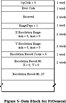 Figure 5–Data Block for PrGeneral
Here is the data block returned by the LaserWriter:
Figure 5–Data Block for PrGeneral
Here is the data block returned by the LaserWriter:
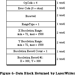 Figure 6–Data Block Returned by the LaserWriter
Notice that all the resolution range numbers are the same for this printer. There is only one resolution record, which gives the physical X and Y resolutions of the printer (300 x 300).
Below is the data block returned by the ImageWriter.
Figure 6–Data Block Returned by the LaserWriter
Notice that all the resolution range numbers are the same for this printer. There is only one resolution record, which gives the physical X and Y resolutions of the printer (300 x 300).
Below is the data block returned by the ImageWriter.
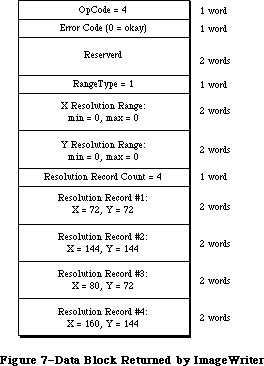 Figure 7–Data Block Returned by the ImageWriter
All the resolution range values are zero, because only discrete resolutions can be specified for the ImageWriter. There are four resolution records giving these discrete physical resolutions.
GetRslData always returns the same information for a particular printer type—it is not dependent on what the user does or on printer configuration information.
_______________________________________________________________________________
»SetRsl
SetRsl (iOpCode = 5) is used to specify the desired imaging resolution, after using GetRslData to determine a workable pair of values. Below is the format of the data block:
TSetRslBlk = RECORD {data block for SetRsl call}
iOpCode: Integer; {input; = setRslOp}
iError: Integer; {output}
lReserved: LongInt; {reserved for future use}
hPrint: THPrint; {input; handle to a valid print record}
iXRsl: Integer; {input; desired X resolution}
iYRsl: Integer; {input; desired Y resolution}
END;
The hPrint parameter contains the handle of a print record that has previously been passed to PrValidate. If the call executes successfully, the print record is updated with the new resolution; the data block comes back with 0 for the error and is otherwise unchanged. If the desired resolution is not supported, the error is set to noSuchRsl and the resolution fields are set to the
printer’s default resolution
You can undo the effect of a previous call to SetRsl by making another call that specifies an unsupported resolution (such as 0 x 0), forcing the default resolution.
_______________________________________________________________________________
»DraftBits
DraftBits (iOpCode = 6) is implemented on both the ImageWriter and the LaserWriter. On the LaserWriter it does nothing, because the LaserWriter is always in draft mode and can always print bitmaps. Here is the format of the data block:
TDftBitsBlk = RECORD {data block for DraftBits and }
{ NoDraftBits calls}
iOpCode: Integer; {input; = draftBitsOp or noDraftBitsOp}
iError: Integer; {output}
lReserved: LongInt; {reserved for future use}
hPrint: THPrint; {input; handle to a valid print record}
END;
The hPrint parameter contains the handle of a print record that has previously been passed to PrValidate.
This call forces draft-mode (immediate) printing, and will allow bitmaps to be printed via CopyBits calls. The virtue of this is that you avoid spooling large masses of bitmap data onto the disk, and you also get better performance.
The following restrictions apply:
• This call should be made before bringing up the print dialog boxes
because it affects their appearance. On the ImageWriter, calling
DraftBits disables the landscape icon in the Style dialog, and the
Best, Faster, and Draft buttons in the Job dialog box.
• If the printer does not support draft mode, already prints bitmaps
in draft mode, or does not print bitmaps at all, this call does nothing.
• Only text and bitmaps can be printed.
• As in the normal draft mode, landscape format is not allowed.
• Everything on the page must be strictly Y-sorted; that is, no reverse
paper motion between one string or bitmap and the next. This means
you can’t have two or more objects (text or bitmaps) side by side; the
top boundary of each object must be no higher than the bottom of the
preceding object.
The last restriction is important. If you violate it, you will not like the results. However, if you want two or more bitmaps side by side, you can combine them into one before calling CopyBits to print the result. Similarly, if you are just printing bitmaps you can rotate them yourself to achieve landscape printing.
_______________________________________________________________________________
»NoDraftBits
NoDraftBits (iOpCode = 7) is implemented on both the ImageWriter and the LaserWriter. On the LaserWriter it does nothing, since the LaserWriter is always in draft mode and can always print bitmaps. The format of the data block is the same as that for the DraftBits call. This call cancels the effect of any preceding DraftBits call. If there was no preceding DraftBits call, or the printer does not support draft-mode printing anyway, this call does nothing.
_______________________________________________________________________________
»GetRotn
GetRotn (iOpCode = 8) is implemented on the ImageWriter and LaserWriter. Here is the format of the data block:
TGetRotnBlk = RECORD {data block for GetRotn call}
iOpCode: Integer; {input; = getRotnOp}
iError: Integer; {output}
lReserved: LongInt; {reserved for future use}
hPrint: THPrint; {input; handle to a valid }
{ print record}
fLandscape: Boolean; {output; Boolean flag}
bXtra: SignedByte; {reserved}
END;
The hPrint parameter contains a handle to a print record that has previously been passed to PrValidate.
If landscape orientation is selected in the print record, then fLandscape is true.
_______________________________________________________________________________
»Using PrGeneral
SetRsl and DraftBits calls may require the print code to suppress certain options in the Style and/or Job dialog boxes, therefore they should always be called before any call to the Style or Job dialogs. An application might use PrGeneral as follows:
• Get a new print record by calling PrintDefault, or take an existing
one from a document and call PrValidate on it.
• Call GetRslData to find out what the printer is capable of, and decide
what resolution to use. Check PrError to be sure the PrGeneral call
is supported on this version of the print code; if the error is
ResNotFound, you have older print code and must print accordingly.
But if the PrError return is 0, proceed as follows:
• Call SetRsl with the print record and the desired resolution if you wish.
• Call DraftBits to invoke the printing of bitmaps in draft mode if you wish.
If you call either SetRsl or DraftBits, you should do so before the user sees either of the printing dialog boxes.
_______________________________________________________________________________
»THE PRINTER DRIVER
_______________________________________________________________________________
The Printing Manager provides a high-level interface that interprets QuickDraw commands for printing; it also provides a low-level interface that lets you directly access the Printer Driver.
Note: You should not use the high-level and low-level calls together.
The Printer Driver is the device driver that communicates with a printer. You only need to read this section if you’re interested in low-level printing or writing your own device driver. For more information, see the Device Manager chapter.
The printer resource file for each type of printer includes a device driver for that printer. When the user chooses a printer, the printer’s device driver becomes the active Printer Driver.
You can communicate with the Printer Driver via the following low-level routines:
• PrDrvrOpen opens the Printer Driver; it remains open until you
call PrDrvrClose.
• PrCtlCall enables you to perform low-level printing operations
such as bit map printing and direct streaming of text to the printer.
• PrDrvrVers tells you the version number of the Printer Driver.
• PrDrvrDCE gets a handle to the driver’s device control entry.
_______________________________________________________________________________
»Low-Level Driver Access Routines
The routines in this section are used for communicating directly with the Printer Driver.
PROCEDURE PrDrvrOpen; [Not in ROM]
PrDrvrOpen opens the Printer Driver, reading it into memory if necessary.
PROCEDURE PrDrvrClose; [Not in ROM]
PrDrvrClose closes the Printer Driver, releasing the memory it occupies.
(Notice that PrClose doesn’t close the Printer Driver.)
PROCEDURE PrCtlCall (iWhichCtl: INTEGER; lParam1,lParam2,lParam3: LONGINT);
[Not in ROM]
PrCtlCall calls the Printer Driver’s control routine. The iWhichCtl parameter identifies the operation to perform. The following values are predefined:
CONST iPrBitsCtl = 4; {bit map printing}
iPrIOCtl = 5; {text streaming}
iPrDevCtl = 7; {printer control}
These operations are described in detail in the following sections of this chapter. The meanings of the lParam1, lParam2, and lParam3 parameters depend on the operation.
Note: Advanced programmers: If you’re making a direct Device Manager
Control call, iWhichCtl will be the csCode parameter, and lParam1,
lParam2, and lParam3 will be csParam, csParam+4, and csParam+8.
FUNCTION PrDrvrDCE : Handle; [Not in ROM]
PrDrvrDCE returns a handle to the Printer Driver’s device control entry.
FUNCTION PrDrvrVers : INTEGER; [Not in ROM]
PrDrvrVers returns the version number of the Printer Driver in the system resource file.
The version number of the Printing Manager is available as the predefined constant iPrRelease. You may want to compare the result of PrDrvrVers with iPrRelease to see if the Printer Driver in the resource file is the most recent version.
_______________________________________________________________________________
»Printer Control
The iPrDevCtl parameter to PrCtlCall is used for several printer control operations. The high-order word of the lParam1 parameter specifies the operation to perform:
CONST
iPrBitsCtl = 4; {the Bitmap Print Proc's ctl number}
lScreenBits = $00000000; {the Bitmap Print Proc's Screen Bitmap param}
lPaintBits = $00000001; {the Bitmap Print Proc's Paint (sq pix) param}
lHiScreenBits = $00000002; {the Bitmap Print Proc's Screen Bitmap param}
lHiPaintBits = $00000003; {the Bitmap Print Proc's Paint (sq pix) param}
iPrIOCtl = 5; {the Raw Byte IO Proc's ctl number}
iPrEvtCtl = 6; {the PrEvent Proc's ctl number; use with Sony }
{ printers and one of these CParams:}
lPrEvtAll = $0002FFFD; {PrEvent Proc's CParam for the whole screen}
lPrEvtTop = $0001FFFD {PrEvent Proc's CParam for the top window}
iPrDevCtl = 7; {the PrDevCtl Proc's ctl number}
lPrReset = $00010000; {OBSOLETE: Use lPrDocOpen instead}
lPrDocOpen = $00010000; {alias for reset}
lPrPageEnd = $00020000; {OBSOLETE: Use lPrPageClose instead}
lPrPageClose = $00020000; {alias for end page}
lPrLineFeed = $00030000; {the PrDevCtl Proc's CParam for paper advance}
lPrLFStd = $0003FFFF; {the PrDevCtl Proc's CParam for std paper adv}
lPrPageOpen = $00040000; {the PrDevCtl Proc's CParam for PageOpen}
lPrDocClose = $00050000; {the PrDevCtl Proc's CParam for DocClose}
Other values that may be shown in the interface file are used only by the
Macintosh system. The low-order word of lParam1 may specify additional information. The lParam2 and lParam3 parameters should always be 0.
Before starting to print, use
PrCtlCall (iPrDevCtl, lPrDocOpen, 0,0);
PrCtlCall (iPrDevCtl, lPrPageOpen, 0, 0);
to reset the printer to its standard initial state. This call should be made only once per document. You can also specify the number of copies to make in the low-order byte of this parameter; for example, a value of $00010002 specifies two copies.
The lPrLineFeed and lPrLFStd parameters allow you to achieve the effect of carriage returns and line feeds in a printer-independent way:
• LPrLineFeed specifies a carriage return only (with a line feed of 0).
• lPrLFStd causes a carriage return and advances the paper by 1/6 inch
(the standard “CR LF” sequence).
You can also specify the exact number of dots the paper advances in the low-order word of the lParam1 parameter. For example, a value of $00030008 for lParam1 causes a carriage return and advances the paper eight dots.
You should use these methods instead of sending carriage returns and line feeds directly to the printer.
The call
PrCtlCall (iPrDevCtl, lPrPageClose, 0, 0);
PrCtlCall (iPrDevCtl, lPrDocClose, 0, 0);
does whatever is appropriate for the given printer at the end of each page, such as sending a form feed character and advancing past the paper fold. You should use this call instead of just sending a form feed yourself.
_______________________________________________________________________________
»Bit Map Printing
To send all or part of a QuickDraw bit map directly to the printer, use
PrCtlCall(iPrBitsCtl,pBitMap,pPortRect,lControl)
The pBitMap parameter is a pointer to a QuickDraw bit map; pPortRect is a pointer to the rectangle to be printed, in the coordinates of the printing grafPort.
LControl should be one of the following predefined constants:
CONST lScreenBits = 0; {default for printer}
lPaintBits = 1; {square dots (72 by 72)}
The Imagewriter, in standard resolution, normally prints rectangular dots that are taller than they are wide (80 dots per inch horizontally by 72 vertically). Since the Macintosh 128K and 512K screen has square pixels (approximately 72 per inch both horizontally and vertically), lPaintBits gives a truer reproduction of the screen, although printing is somewhat slower.
On the LaserWriter, lControl should always be set to lPaintBits.
Putting all this together, you can print the entire screen at the default setting with
PrCtlCall(iPrBitsCtl,ORD(@screenBits),
ORD(@screenBits.bounds),lScreenBits)
To print the contents of a single window in square dots, use
PrCtlCall(iPrBitsCtl,ORD(@theWindow^.portBits),
ORD(@theWindow^.portRect),lPaintBits)
_______________________________________________________________________________
»Text Streaming
Text streaming is useful for fast printing of text when speed is more important than fancy formatting or visual fidelity. It gives you full access to the printer’s native text facilities (such as control or escape sequences for boldface, italic, underlining, or condensed or extended type), but makes no use of QuickDraw.
You can send a stream of characters (including control and escape sequences) directly to the printer with
PrCtlCall(iPrIOCtl,pBuf,lBufCount,0)
The pBuf parameter is a pointer to the beginning of the text. The low-order word of lBufCount is the number of bytes to transfer; the high-order word must be 0.
Warning: Relying on specific printer capabilities and control sequences will
make your application printer-dependent. You can use iPrDevCtl to
perform form feeds and line feeds in a printer-independent way.
Note: Advanced programmers who need more information about sending commands
directly to the LaserWriter should see Macintosh Technical Notes and
the Apple LaserWriter Reference.
_______________________________________________________________________________
»SUMMARY OF THE PRINTING MANAGER
_______________________________________________________________________________
Constants
CONST
{ Printing methods }
bDraftLoop = 0; {draft printing}
bSpoolLoop = 1; {spool printing}
{ Maximum number of pages in a spool file }
iPFMaxPgs = 128;
{ Result codes }
noErr = 0; {no error}
iPrSavPFil = –1; {saving spool file}
controlErr = –17; {unimplemented control instruction}
iIOAbort = –27; {I/O abort error}
iMemFullErr = –108; {not enough room in heap zone}
iPrAbort = 128; {application or user requested abort}
{ The following result codes are LaserWriter-specific }
–4101; { Printer not found or closed }
–4100; { Connection just closed }
–4099; { Write request too big }
–4098; { Request already active }
–4097; { Bad connection refnum }
–4096; { No free CCBs (Connect Control Blocks) available }
–8133; { PostScript error occurred during transmission }
{ of data to printer. Most often caused by a bug }
{ in the PostScript code being downloaded. }
–8132; { Timeout occured. This error is returned when }
{ no data has been sent to the printer for 2 }
{ minutes. Usually caused by extremely long }
{ imaging times. }
{ PrCtlCall parameters }
iPrBitsCtl = 4; {the Bitmap Print Proc's ctl number}
lScreenBits = $00000000; {the Bitmap Print Proc's Screen Bitmap param}
lPaintBits = $00000001; {the Bitmap Print Proc's Paint (sq pix) param}
lHiScreenBits = $00000002; {the Bitmap Print Proc's Screen Bitmap param}
lHiPaintBits = $00000003; {the Bitmap Print Proc's Paint (sq pix) param}
iPrIOCtl = 5; {the Raw Byte IO Proc's ctl number}
iPrEvtCtl = 6; {the PrEvent Proc's ctl number; use with Sony }
{ printers and one of these CParams:}
lPrEvtAll = $0002FFFD; {PrEvent Proc's CParam for the whole screen}
lPrEvtTop = $0001FFFD {PrEvent Proc's CParam for the top window}
iPrDevCtl = 7; {the PrDevCtl Proc's ctl number}
lPrReset = $00010000; {OBSOLETE: Use lPrDocOpen instead}
lPrDocOpen = $00010000; {alias for reset}
lPrPageEnd = $00020000; {OBSOLETE: Use lPrPageClose instead}
lPrPageClose = $00020000; {alias for end page}
lPrLineFeed = $00030000; {the PrDevCtl Proc's CParam for paper advance}
lPrLFStd = $0003FFFF; {the PrDevCtl Proc's CParam for std paper adv}
lPrPageOpen = $00040000; {the PrDevCtl Proc's CParam for PageOpen}
lPrDocClose = $00050000; {the PrDevCtl Proc's CParam for DocClose}
{PrGeneral iOpCode values}
GetRslData = 4; {get resolution data}
SetRsl = 5; {set resolution}
DraftBits = 6; {bitmaps in draft mode}
NoDraftBits = 7; {no bitmaps in draft mode}
GetRotn = 8; {get rotation}
{PrGeneral error codes}
NoErr = 0; {no error}
NoSuchRsl = 1; {the resolution you chose isn't available}
OpNotImpl = 2; {the driver doesn't support this opcode}
_______________________________________________________________________________
Data Types
TYPE
TPPrPort = ^TPrPort;
TPrPort = RECORD
gPort: GrafPort; {grafPort to draw in}
{more fields for internal use}
END;
THPrint = ^TPPrint;
TPPrint = ^TPrint;
TPrint = RECORD
iPrVersion: INTEGER; {Printing Manager version}
prInfo: TPrInfo; {printer information subrecord}
rPaper: Rect; {paper rectangle}
prStl: TPrStl; {additional device information}
prInfoPT: TPrInfo; {used internally}
prXInfo: TPrXInfo; {additional device information}
prJob: TPrJob; {job subrecord}
printX: ARRAY[1..19] OF INTEGER {not used}
END;
TPrInfo = RECORD
iDev: INTEGER; {used internally}
iVRes: INTEGER; {vertical resolution of printer}
iHRes: INTEGER; {horizontal resolution of printer}
rPage: Rect {page rectangle}
END;
TPrJob = RECORD
iFstPage: INTEGER; {first page to print}
iLstPage: INTEGER; {last page to print}
iCopies: INTEGER; {number of copies}
bJDocLoop: SignedByte; {printing method}
fFromUsr: BOOLEAN; {used internally}
pIdleProc: ProcPtr; {background procedure}
pFileName: StringPtr; {spool file name}
iFileVol: INTEGER; {spool file volume reference number}
bFileVers: SignedByte; {spool file version number}
bJobX: SignedByte {used internally}
END;
TPrStl = RECORD
wDev: INTEGER; {high byte specifies device}
{more fields for internal use}
END;
TPrXInfo = RECORD
iRowBytes: INTEGER; {used internally}
iBandV: INTEGER; {used internally}
iBandH: INTEGER; {used internally}
iDevBytes: INTEGER; {size of buffer}
{more fields for internal use}
END;
TPRect = ^Rect;
TPrStatus = RECORD
iTotPages: INTEGER; {number of pages in spool file}
iCurPage: INTEGER; {page being printed}
iTotCopies: INTEGER; {number of copies requested}
iCurCopy: INTEGER; {copy being printed}
iTotBands: INTEGER; {used internally}
iCurBand: INTEGER; {used internally}
fPgDirty: BOOLEAN; {TRUE if started printing page}
fImaging: BOOLEAN; {used internally}
hPrint: THPrint; {print record}
pPrPort: TPPrPort; {printing grafPort}
hPic: PicHandle {used internally}
END;
TGnlData = RECORD
{1st 8 bytes are common for all PrGeneral calls);
iOpCode: Integer; {input}
iError: Integer; {output}
lReserved: LongInt; {reserved for future use}
{more fields here, depending on particular call}
END;
TRslRg = RECORD {used in TGetRslBlk}
iMin: Integer; {0 if printer supports only discrete resolutions}
iMax: Integer; {0 if printer supports only discrete resolutions}
END;
TRslRec = RECORD {used in TGetRslBlk}
iXRsl: Integer; {a discrete, physical X resolution}
iYRsl: Integer; {a discrete, physical Y resolution}
END;
TGetRslBlk = RECORD {data block for GetRslData call}
iOpCode: Integer; {input; = getRslDataOp}
iError: Integer; {output}
lReserved: LongInt; {reserved for future use}
iRgType: Integer; {output; version number}
XRslRg: TRslRg; {output; range of X resolutions}
YRslRg: TRslRg; {output; range of Y resolutions}
iRslRecCnt: Integer; {output; how many RslRecs follow}
rgRslRec: ARRAY[1..27] OF TRslRec; {output; number filled }
{ depends on printer type}
END;
TSetRslBlk = RECORD {data block for SetRsl call}
iOpCode: Integer; {input; = setRslOp}
iError: Integer; {output}
lReserved: LongInt; {reserved for future use}
hPrint: THPrint; {input; handle to a valid print record}
iXRsl: Integer; {input; desired X resolution}
iYRsl: Integer; {input; desired Y resolution}
END;
TDftBitsBlk = RECORD {data block for DraftBits and }
{ NoDraftBits calls}
iOpCode: Integer; {input; = draftBitsOp or noDraftBitsOp}
iError: Integer; {output}
lReserved: LongInt; {reserved for future use}
hPrint: THPrint; {input; handle to a valid print record}
END;
TGetRotnBlk = RECORD {data block for GetRotn call}
iOpCode: Integer; {input; = getRotnOp}
iError: Integer; {output}
lReserved: LongInt; {reserved for future use}
hPrint: THPrint; {input; handle to a valid }
{ print record}
fLandscape: Boolean; {output; Boolean flag}
bXtra: SignedByte; {reserved}
END;
_______________________________________________________________________________
Routines
PROCEDURE PrOpen;
PROCEDURE PrClose;
PROCEDURE PrintDefault (hPrint: THPrint);
FUNCTION PrValidate (hPrint: THPrint) : Boolean;
FUNCTION PrStlDialog (hPrint: THPrint) : Boolean;
FUNCTION PrJobDialog (hPrint: THPrint) : Boolean;
PROCEDURE PrJobMerge (hPrintSrc, hPrintDst: THPrint);
FUNCTION PrOpenDoc (hPrint: THPrint; pPrPort: TPPrPort;
pIOBuf: Ptr): TPPrPort;
PROCEDURE PrCloseDoc (pPrPort: TPPrPort);
PROCEDURE PrOpenPage (pPrPort: TPPrPort; pPageFrame: TPRect);
PROCEDURE PrClosePage (pPrPort: TPPrPort);
PROCEDURE PrPicFile (hPrint: THPrint; pPrPort: TPPrPort; pIOBuf: Ptr;
pDevBuf: Ptr; VAR PrStatus: TPrStatus);
FUNCTION PrError: Integer;
PROCEDURE PrSetError (iErr: Integer);
PROCEDURE PrDrvrOpen;
PROCEDURE PrDrvrClose;
PROCEDURE PrCtlCall (iWhichCtl: Integer;
lParam1, lParam2, lParam3: LongInt);
FUNCTION PrDrvrDCE: Handle;
FUNCTION PrDrvrVers: Integer;
PROCEDURE PrGeneral (pData: Ptr);
_______________________________________________________________________________
Assembly-Language Information
Constants
; Printing methods
bDraftLoop .EQU 0 ;draft printing
bSpoolLoop .EQU 1 ;spool printing
; Result codes
noErr .EQU 0 ;no error
iPrSavPFil .EQU –1 ;saving spool file
controlErr .EQU –17 ;unimplemented control instruction
iIOAbort .EQU –27 ;I/O abort error
iMemFullErr .EQU –108 ;not enough room in heap zone
iPrAbort .EQU 128 ;application or user requested abort
; Printer Driver Control call parameters
iPrDevCtl .EQU 7 ;printer control
lPrReset .EQU 1 ; reset printer
iPrLineFeed .EQU 3 ; carriage return/paper advance
iPrLFSixth .EQU 3 ;standard 1/6-inch line feed
lPrPageEnd .EQU 2 ; end page
iPrBitsCtl .EQU 4 ;bit map printing
lScreenBits .EQU 0 ; default for printer
lPaintBits .EQU 1 ; square dots (72 by 72)
iPrIOCtl .EQU 5 ;text streaming
; Printer Driver information
iPrDrvrRef .EQU –3 ;Printer Driver reference number
Printing GrafPort Data Structure
gPort GrafPort to draw in (portRec bytes)
iPrPortSize Size in bytes of printing grafPort
Print Record Data Structure
iPrVersion Printing Manager version (word)
prInfo Printer information subrecord (14 bytes)
rPaper Paper rectangle (8 bytes)
prStl Additional device information (8 bytes)
prXInfo Additional device information (16 bytes)
prJob Job subrecord (iPrJobSize bytes)
iPrintSize Size in bytes of print record
Structure of Printer Information Subrecord
iVRes Vertical resolution of printer (word)
iHRes Horizontal resolution of printer (word)
rPage Page rectangle (8 bytes)
Structure of Job Subrecord
iFstPage First page to print (word)
iLstPage Last page to print (word)
iCopies Number of copies (word)
bJDocLoop Printing method (byte)
pIdleProc Address of background procedure
pFileName Pointer to spool file name (preceded by length byte)
iFileVol Spool file volume reference number (word)
bFileVers Spool file version number (byte)
iPrJobSize Size in bytes of job subrecord
Structure of PrXInfo Subrecord
iDevBytes Size of buffer (word)
Structure of Printer Status Record
iTotPages Number of pages in spool file (word)
iCurPage Page being printed (word)
iTotCopies Number of copies requested (word)
iCurCopy Copy being printed (word)
fPgDirty Nonzero if started printing page (byte)
hPrint Handle to print record
pPrPort Pointer to printing grafPort
iPrStatSize Size in bytes of printer status record
Variables
PrintErr Result code from last Printing Manager routine (word)
Further Reference:
_______________________________________________________________________________
Resource Manager
QuickDraw
Dialog Manager
Device Manager
Technical Note #33, ImageWriter II Paper Motion
Technical Note #72, Optimizing for the LaserWriter — Techniques
Technical Note #73, Color Printing
Technical Note #91, Optimizing for the LaserWriter—Picture Comments
Technical Note #92, The Appearance of Text
Technical Note #95, How To Add Items to the Print Dialogs
Technical Note #118, How to Check and Handle Printing Errors
Technical Note #122, Device-Independent Printing
Technical Note #123, Bugs in LaserWriter ROMs
Technical Note #124, Low-Level Printing Calls With AppleTalk ImageWriters
Technical Note #125, Effect of Spool-a-page/Print-a-page on Shared Printers
Technical Note #128, PrGeneral
Technical Note #133, Am I Talking To A Spooler?
Technical Note #149, Document Names and the Printing Manager
Technical Note #152, Using Laser Prep Routines
Technical Note #161, When to Call _PrOpen and _PrClose
Technical Note #173, PrGeneral Bug
Technical Note #175, SetLineWidth Revealed
Technical Note #183, Position-Independent PostScript
Technical Note #192, Surprises in LaserWriter 5.0 and newer
Technical Note #217, Where Have My Font Icons Gone?
“Apple LaserWriter Reference”
Figure 7–Data Block Returned by the ImageWriter
All the resolution range values are zero, because only discrete resolutions can be specified for the ImageWriter. There are four resolution records giving these discrete physical resolutions.
GetRslData always returns the same information for a particular printer type—it is not dependent on what the user does or on printer configuration information.
_______________________________________________________________________________
»SetRsl
SetRsl (iOpCode = 5) is used to specify the desired imaging resolution, after using GetRslData to determine a workable pair of values. Below is the format of the data block:
TSetRslBlk = RECORD {data block for SetRsl call}
iOpCode: Integer; {input; = setRslOp}
iError: Integer; {output}
lReserved: LongInt; {reserved for future use}
hPrint: THPrint; {input; handle to a valid print record}
iXRsl: Integer; {input; desired X resolution}
iYRsl: Integer; {input; desired Y resolution}
END;
The hPrint parameter contains the handle of a print record that has previously been passed to PrValidate. If the call executes successfully, the print record is updated with the new resolution; the data block comes back with 0 for the error and is otherwise unchanged. If the desired resolution is not supported, the error is set to noSuchRsl and the resolution fields are set to the
printer’s default resolution
You can undo the effect of a previous call to SetRsl by making another call that specifies an unsupported resolution (such as 0 x 0), forcing the default resolution.
_______________________________________________________________________________
»DraftBits
DraftBits (iOpCode = 6) is implemented on both the ImageWriter and the LaserWriter. On the LaserWriter it does nothing, because the LaserWriter is always in draft mode and can always print bitmaps. Here is the format of the data block:
TDftBitsBlk = RECORD {data block for DraftBits and }
{ NoDraftBits calls}
iOpCode: Integer; {input; = draftBitsOp or noDraftBitsOp}
iError: Integer; {output}
lReserved: LongInt; {reserved for future use}
hPrint: THPrint; {input; handle to a valid print record}
END;
The hPrint parameter contains the handle of a print record that has previously been passed to PrValidate.
This call forces draft-mode (immediate) printing, and will allow bitmaps to be printed via CopyBits calls. The virtue of this is that you avoid spooling large masses of bitmap data onto the disk, and you also get better performance.
The following restrictions apply:
• This call should be made before bringing up the print dialog boxes
because it affects their appearance. On the ImageWriter, calling
DraftBits disables the landscape icon in the Style dialog, and the
Best, Faster, and Draft buttons in the Job dialog box.
• If the printer does not support draft mode, already prints bitmaps
in draft mode, or does not print bitmaps at all, this call does nothing.
• Only text and bitmaps can be printed.
• As in the normal draft mode, landscape format is not allowed.
• Everything on the page must be strictly Y-sorted; that is, no reverse
paper motion between one string or bitmap and the next. This means
you can’t have two or more objects (text or bitmaps) side by side; the
top boundary of each object must be no higher than the bottom of the
preceding object.
The last restriction is important. If you violate it, you will not like the results. However, if you want two or more bitmaps side by side, you can combine them into one before calling CopyBits to print the result. Similarly, if you are just printing bitmaps you can rotate them yourself to achieve landscape printing.
_______________________________________________________________________________
»NoDraftBits
NoDraftBits (iOpCode = 7) is implemented on both the ImageWriter and the LaserWriter. On the LaserWriter it does nothing, since the LaserWriter is always in draft mode and can always print bitmaps. The format of the data block is the same as that for the DraftBits call. This call cancels the effect of any preceding DraftBits call. If there was no preceding DraftBits call, or the printer does not support draft-mode printing anyway, this call does nothing.
_______________________________________________________________________________
»GetRotn
GetRotn (iOpCode = 8) is implemented on the ImageWriter and LaserWriter. Here is the format of the data block:
TGetRotnBlk = RECORD {data block for GetRotn call}
iOpCode: Integer; {input; = getRotnOp}
iError: Integer; {output}
lReserved: LongInt; {reserved for future use}
hPrint: THPrint; {input; handle to a valid }
{ print record}
fLandscape: Boolean; {output; Boolean flag}
bXtra: SignedByte; {reserved}
END;
The hPrint parameter contains a handle to a print record that has previously been passed to PrValidate.
If landscape orientation is selected in the print record, then fLandscape is true.
_______________________________________________________________________________
»Using PrGeneral
SetRsl and DraftBits calls may require the print code to suppress certain options in the Style and/or Job dialog boxes, therefore they should always be called before any call to the Style or Job dialogs. An application might use PrGeneral as follows:
• Get a new print record by calling PrintDefault, or take an existing
one from a document and call PrValidate on it.
• Call GetRslData to find out what the printer is capable of, and decide
what resolution to use. Check PrError to be sure the PrGeneral call
is supported on this version of the print code; if the error is
ResNotFound, you have older print code and must print accordingly.
But if the PrError return is 0, proceed as follows:
• Call SetRsl with the print record and the desired resolution if you wish.
• Call DraftBits to invoke the printing of bitmaps in draft mode if you wish.
If you call either SetRsl or DraftBits, you should do so before the user sees either of the printing dialog boxes.
_______________________________________________________________________________
»THE PRINTER DRIVER
_______________________________________________________________________________
The Printing Manager provides a high-level interface that interprets QuickDraw commands for printing; it also provides a low-level interface that lets you directly access the Printer Driver.
Note: You should not use the high-level and low-level calls together.
The Printer Driver is the device driver that communicates with a printer. You only need to read this section if you’re interested in low-level printing or writing your own device driver. For more information, see the Device Manager chapter.
The printer resource file for each type of printer includes a device driver for that printer. When the user chooses a printer, the printer’s device driver becomes the active Printer Driver.
You can communicate with the Printer Driver via the following low-level routines:
• PrDrvrOpen opens the Printer Driver; it remains open until you
call PrDrvrClose.
• PrCtlCall enables you to perform low-level printing operations
such as bit map printing and direct streaming of text to the printer.
• PrDrvrVers tells you the version number of the Printer Driver.
• PrDrvrDCE gets a handle to the driver’s device control entry.
_______________________________________________________________________________
»Low-Level Driver Access Routines
The routines in this section are used for communicating directly with the Printer Driver.
PROCEDURE PrDrvrOpen; [Not in ROM]
PrDrvrOpen opens the Printer Driver, reading it into memory if necessary.
PROCEDURE PrDrvrClose; [Not in ROM]
PrDrvrClose closes the Printer Driver, releasing the memory it occupies.
(Notice that PrClose doesn’t close the Printer Driver.)
PROCEDURE PrCtlCall (iWhichCtl: INTEGER; lParam1,lParam2,lParam3: LONGINT);
[Not in ROM]
PrCtlCall calls the Printer Driver’s control routine. The iWhichCtl parameter identifies the operation to perform. The following values are predefined:
CONST iPrBitsCtl = 4; {bit map printing}
iPrIOCtl = 5; {text streaming}
iPrDevCtl = 7; {printer control}
These operations are described in detail in the following sections of this chapter. The meanings of the lParam1, lParam2, and lParam3 parameters depend on the operation.
Note: Advanced programmers: If you’re making a direct Device Manager
Control call, iWhichCtl will be the csCode parameter, and lParam1,
lParam2, and lParam3 will be csParam, csParam+4, and csParam+8.
FUNCTION PrDrvrDCE : Handle; [Not in ROM]
PrDrvrDCE returns a handle to the Printer Driver’s device control entry.
FUNCTION PrDrvrVers : INTEGER; [Not in ROM]
PrDrvrVers returns the version number of the Printer Driver in the system resource file.
The version number of the Printing Manager is available as the predefined constant iPrRelease. You may want to compare the result of PrDrvrVers with iPrRelease to see if the Printer Driver in the resource file is the most recent version.
_______________________________________________________________________________
»Printer Control
The iPrDevCtl parameter to PrCtlCall is used for several printer control operations. The high-order word of the lParam1 parameter specifies the operation to perform:
CONST
iPrBitsCtl = 4; {the Bitmap Print Proc's ctl number}
lScreenBits = $00000000; {the Bitmap Print Proc's Screen Bitmap param}
lPaintBits = $00000001; {the Bitmap Print Proc's Paint (sq pix) param}
lHiScreenBits = $00000002; {the Bitmap Print Proc's Screen Bitmap param}
lHiPaintBits = $00000003; {the Bitmap Print Proc's Paint (sq pix) param}
iPrIOCtl = 5; {the Raw Byte IO Proc's ctl number}
iPrEvtCtl = 6; {the PrEvent Proc's ctl number; use with Sony }
{ printers and one of these CParams:}
lPrEvtAll = $0002FFFD; {PrEvent Proc's CParam for the whole screen}
lPrEvtTop = $0001FFFD {PrEvent Proc's CParam for the top window}
iPrDevCtl = 7; {the PrDevCtl Proc's ctl number}
lPrReset = $00010000; {OBSOLETE: Use lPrDocOpen instead}
lPrDocOpen = $00010000; {alias for reset}
lPrPageEnd = $00020000; {OBSOLETE: Use lPrPageClose instead}
lPrPageClose = $00020000; {alias for end page}
lPrLineFeed = $00030000; {the PrDevCtl Proc's CParam for paper advance}
lPrLFStd = $0003FFFF; {the PrDevCtl Proc's CParam for std paper adv}
lPrPageOpen = $00040000; {the PrDevCtl Proc's CParam for PageOpen}
lPrDocClose = $00050000; {the PrDevCtl Proc's CParam for DocClose}
Other values that may be shown in the interface file are used only by the
Macintosh system. The low-order word of lParam1 may specify additional information. The lParam2 and lParam3 parameters should always be 0.
Before starting to print, use
PrCtlCall (iPrDevCtl, lPrDocOpen, 0,0);
PrCtlCall (iPrDevCtl, lPrPageOpen, 0, 0);
to reset the printer to its standard initial state. This call should be made only once per document. You can also specify the number of copies to make in the low-order byte of this parameter; for example, a value of $00010002 specifies two copies.
The lPrLineFeed and lPrLFStd parameters allow you to achieve the effect of carriage returns and line feeds in a printer-independent way:
• LPrLineFeed specifies a carriage return only (with a line feed of 0).
• lPrLFStd causes a carriage return and advances the paper by 1/6 inch
(the standard “CR LF” sequence).
You can also specify the exact number of dots the paper advances in the low-order word of the lParam1 parameter. For example, a value of $00030008 for lParam1 causes a carriage return and advances the paper eight dots.
You should use these methods instead of sending carriage returns and line feeds directly to the printer.
The call
PrCtlCall (iPrDevCtl, lPrPageClose, 0, 0);
PrCtlCall (iPrDevCtl, lPrDocClose, 0, 0);
does whatever is appropriate for the given printer at the end of each page, such as sending a form feed character and advancing past the paper fold. You should use this call instead of just sending a form feed yourself.
_______________________________________________________________________________
»Bit Map Printing
To send all or part of a QuickDraw bit map directly to the printer, use
PrCtlCall(iPrBitsCtl,pBitMap,pPortRect,lControl)
The pBitMap parameter is a pointer to a QuickDraw bit map; pPortRect is a pointer to the rectangle to be printed, in the coordinates of the printing grafPort.
LControl should be one of the following predefined constants:
CONST lScreenBits = 0; {default for printer}
lPaintBits = 1; {square dots (72 by 72)}
The Imagewriter, in standard resolution, normally prints rectangular dots that are taller than they are wide (80 dots per inch horizontally by 72 vertically). Since the Macintosh 128K and 512K screen has square pixels (approximately 72 per inch both horizontally and vertically), lPaintBits gives a truer reproduction of the screen, although printing is somewhat slower.
On the LaserWriter, lControl should always be set to lPaintBits.
Putting all this together, you can print the entire screen at the default setting with
PrCtlCall(iPrBitsCtl,ORD(@screenBits),
ORD(@screenBits.bounds),lScreenBits)
To print the contents of a single window in square dots, use
PrCtlCall(iPrBitsCtl,ORD(@theWindow^.portBits),
ORD(@theWindow^.portRect),lPaintBits)
_______________________________________________________________________________
»Text Streaming
Text streaming is useful for fast printing of text when speed is more important than fancy formatting or visual fidelity. It gives you full access to the printer’s native text facilities (such as control or escape sequences for boldface, italic, underlining, or condensed or extended type), but makes no use of QuickDraw.
You can send a stream of characters (including control and escape sequences) directly to the printer with
PrCtlCall(iPrIOCtl,pBuf,lBufCount,0)
The pBuf parameter is a pointer to the beginning of the text. The low-order word of lBufCount is the number of bytes to transfer; the high-order word must be 0.
Warning: Relying on specific printer capabilities and control sequences will
make your application printer-dependent. You can use iPrDevCtl to
perform form feeds and line feeds in a printer-independent way.
Note: Advanced programmers who need more information about sending commands
directly to the LaserWriter should see Macintosh Technical Notes and
the Apple LaserWriter Reference.
_______________________________________________________________________________
»SUMMARY OF THE PRINTING MANAGER
_______________________________________________________________________________
Constants
CONST
{ Printing methods }
bDraftLoop = 0; {draft printing}
bSpoolLoop = 1; {spool printing}
{ Maximum number of pages in a spool file }
iPFMaxPgs = 128;
{ Result codes }
noErr = 0; {no error}
iPrSavPFil = –1; {saving spool file}
controlErr = –17; {unimplemented control instruction}
iIOAbort = –27; {I/O abort error}
iMemFullErr = –108; {not enough room in heap zone}
iPrAbort = 128; {application or user requested abort}
{ The following result codes are LaserWriter-specific }
–4101; { Printer not found or closed }
–4100; { Connection just closed }
–4099; { Write request too big }
–4098; { Request already active }
–4097; { Bad connection refnum }
–4096; { No free CCBs (Connect Control Blocks) available }
–8133; { PostScript error occurred during transmission }
{ of data to printer. Most often caused by a bug }
{ in the PostScript code being downloaded. }
–8132; { Timeout occured. This error is returned when }
{ no data has been sent to the printer for 2 }
{ minutes. Usually caused by extremely long }
{ imaging times. }
{ PrCtlCall parameters }
iPrBitsCtl = 4; {the Bitmap Print Proc's ctl number}
lScreenBits = $00000000; {the Bitmap Print Proc's Screen Bitmap param}
lPaintBits = $00000001; {the Bitmap Print Proc's Paint (sq pix) param}
lHiScreenBits = $00000002; {the Bitmap Print Proc's Screen Bitmap param}
lHiPaintBits = $00000003; {the Bitmap Print Proc's Paint (sq pix) param}
iPrIOCtl = 5; {the Raw Byte IO Proc's ctl number}
iPrEvtCtl = 6; {the PrEvent Proc's ctl number; use with Sony }
{ printers and one of these CParams:}
lPrEvtAll = $0002FFFD; {PrEvent Proc's CParam for the whole screen}
lPrEvtTop = $0001FFFD {PrEvent Proc's CParam for the top window}
iPrDevCtl = 7; {the PrDevCtl Proc's ctl number}
lPrReset = $00010000; {OBSOLETE: Use lPrDocOpen instead}
lPrDocOpen = $00010000; {alias for reset}
lPrPageEnd = $00020000; {OBSOLETE: Use lPrPageClose instead}
lPrPageClose = $00020000; {alias for end page}
lPrLineFeed = $00030000; {the PrDevCtl Proc's CParam for paper advance}
lPrLFStd = $0003FFFF; {the PrDevCtl Proc's CParam for std paper adv}
lPrPageOpen = $00040000; {the PrDevCtl Proc's CParam for PageOpen}
lPrDocClose = $00050000; {the PrDevCtl Proc's CParam for DocClose}
{PrGeneral iOpCode values}
GetRslData = 4; {get resolution data}
SetRsl = 5; {set resolution}
DraftBits = 6; {bitmaps in draft mode}
NoDraftBits = 7; {no bitmaps in draft mode}
GetRotn = 8; {get rotation}
{PrGeneral error codes}
NoErr = 0; {no error}
NoSuchRsl = 1; {the resolution you chose isn't available}
OpNotImpl = 2; {the driver doesn't support this opcode}
_______________________________________________________________________________
Data Types
TYPE
TPPrPort = ^TPrPort;
TPrPort = RECORD
gPort: GrafPort; {grafPort to draw in}
{more fields for internal use}
END;
THPrint = ^TPPrint;
TPPrint = ^TPrint;
TPrint = RECORD
iPrVersion: INTEGER; {Printing Manager version}
prInfo: TPrInfo; {printer information subrecord}
rPaper: Rect; {paper rectangle}
prStl: TPrStl; {additional device information}
prInfoPT: TPrInfo; {used internally}
prXInfo: TPrXInfo; {additional device information}
prJob: TPrJob; {job subrecord}
printX: ARRAY[1..19] OF INTEGER {not used}
END;
TPrInfo = RECORD
iDev: INTEGER; {used internally}
iVRes: INTEGER; {vertical resolution of printer}
iHRes: INTEGER; {horizontal resolution of printer}
rPage: Rect {page rectangle}
END;
TPrJob = RECORD
iFstPage: INTEGER; {first page to print}
iLstPage: INTEGER; {last page to print}
iCopies: INTEGER; {number of copies}
bJDocLoop: SignedByte; {printing method}
fFromUsr: BOOLEAN; {used internally}
pIdleProc: ProcPtr; {background procedure}
pFileName: StringPtr; {spool file name}
iFileVol: INTEGER; {spool file volume reference number}
bFileVers: SignedByte; {spool file version number}
bJobX: SignedByte {used internally}
END;
TPrStl = RECORD
wDev: INTEGER; {high byte specifies device}
{more fields for internal use}
END;
TPrXInfo = RECORD
iRowBytes: INTEGER; {used internally}
iBandV: INTEGER; {used internally}
iBandH: INTEGER; {used internally}
iDevBytes: INTEGER; {size of buffer}
{more fields for internal use}
END;
TPRect = ^Rect;
TPrStatus = RECORD
iTotPages: INTEGER; {number of pages in spool file}
iCurPage: INTEGER; {page being printed}
iTotCopies: INTEGER; {number of copies requested}
iCurCopy: INTEGER; {copy being printed}
iTotBands: INTEGER; {used internally}
iCurBand: INTEGER; {used internally}
fPgDirty: BOOLEAN; {TRUE if started printing page}
fImaging: BOOLEAN; {used internally}
hPrint: THPrint; {print record}
pPrPort: TPPrPort; {printing grafPort}
hPic: PicHandle {used internally}
END;
TGnlData = RECORD
{1st 8 bytes are common for all PrGeneral calls);
iOpCode: Integer; {input}
iError: Integer; {output}
lReserved: LongInt; {reserved for future use}
{more fields here, depending on particular call}
END;
TRslRg = RECORD {used in TGetRslBlk}
iMin: Integer; {0 if printer supports only discrete resolutions}
iMax: Integer; {0 if printer supports only discrete resolutions}
END;
TRslRec = RECORD {used in TGetRslBlk}
iXRsl: Integer; {a discrete, physical X resolution}
iYRsl: Integer; {a discrete, physical Y resolution}
END;
TGetRslBlk = RECORD {data block for GetRslData call}
iOpCode: Integer; {input; = getRslDataOp}
iError: Integer; {output}
lReserved: LongInt; {reserved for future use}
iRgType: Integer; {output; version number}
XRslRg: TRslRg; {output; range of X resolutions}
YRslRg: TRslRg; {output; range of Y resolutions}
iRslRecCnt: Integer; {output; how many RslRecs follow}
rgRslRec: ARRAY[1..27] OF TRslRec; {output; number filled }
{ depends on printer type}
END;
TSetRslBlk = RECORD {data block for SetRsl call}
iOpCode: Integer; {input; = setRslOp}
iError: Integer; {output}
lReserved: LongInt; {reserved for future use}
hPrint: THPrint; {input; handle to a valid print record}
iXRsl: Integer; {input; desired X resolution}
iYRsl: Integer; {input; desired Y resolution}
END;
TDftBitsBlk = RECORD {data block for DraftBits and }
{ NoDraftBits calls}
iOpCode: Integer; {input; = draftBitsOp or noDraftBitsOp}
iError: Integer; {output}
lReserved: LongInt; {reserved for future use}
hPrint: THPrint; {input; handle to a valid print record}
END;
TGetRotnBlk = RECORD {data block for GetRotn call}
iOpCode: Integer; {input; = getRotnOp}
iError: Integer; {output}
lReserved: LongInt; {reserved for future use}
hPrint: THPrint; {input; handle to a valid }
{ print record}
fLandscape: Boolean; {output; Boolean flag}
bXtra: SignedByte; {reserved}
END;
_______________________________________________________________________________
Routines
PROCEDURE PrOpen;
PROCEDURE PrClose;
PROCEDURE PrintDefault (hPrint: THPrint);
FUNCTION PrValidate (hPrint: THPrint) : Boolean;
FUNCTION PrStlDialog (hPrint: THPrint) : Boolean;
FUNCTION PrJobDialog (hPrint: THPrint) : Boolean;
PROCEDURE PrJobMerge (hPrintSrc, hPrintDst: THPrint);
FUNCTION PrOpenDoc (hPrint: THPrint; pPrPort: TPPrPort;
pIOBuf: Ptr): TPPrPort;
PROCEDURE PrCloseDoc (pPrPort: TPPrPort);
PROCEDURE PrOpenPage (pPrPort: TPPrPort; pPageFrame: TPRect);
PROCEDURE PrClosePage (pPrPort: TPPrPort);
PROCEDURE PrPicFile (hPrint: THPrint; pPrPort: TPPrPort; pIOBuf: Ptr;
pDevBuf: Ptr; VAR PrStatus: TPrStatus);
FUNCTION PrError: Integer;
PROCEDURE PrSetError (iErr: Integer);
PROCEDURE PrDrvrOpen;
PROCEDURE PrDrvrClose;
PROCEDURE PrCtlCall (iWhichCtl: Integer;
lParam1, lParam2, lParam3: LongInt);
FUNCTION PrDrvrDCE: Handle;
FUNCTION PrDrvrVers: Integer;
PROCEDURE PrGeneral (pData: Ptr);
_______________________________________________________________________________
Assembly-Language Information
Constants
; Printing methods
bDraftLoop .EQU 0 ;draft printing
bSpoolLoop .EQU 1 ;spool printing
; Result codes
noErr .EQU 0 ;no error
iPrSavPFil .EQU –1 ;saving spool file
controlErr .EQU –17 ;unimplemented control instruction
iIOAbort .EQU –27 ;I/O abort error
iMemFullErr .EQU –108 ;not enough room in heap zone
iPrAbort .EQU 128 ;application or user requested abort
; Printer Driver Control call parameters
iPrDevCtl .EQU 7 ;printer control
lPrReset .EQU 1 ; reset printer
iPrLineFeed .EQU 3 ; carriage return/paper advance
iPrLFSixth .EQU 3 ;standard 1/6-inch line feed
lPrPageEnd .EQU 2 ; end page
iPrBitsCtl .EQU 4 ;bit map printing
lScreenBits .EQU 0 ; default for printer
lPaintBits .EQU 1 ; square dots (72 by 72)
iPrIOCtl .EQU 5 ;text streaming
; Printer Driver information
iPrDrvrRef .EQU –3 ;Printer Driver reference number
Printing GrafPort Data Structure
gPort GrafPort to draw in (portRec bytes)
iPrPortSize Size in bytes of printing grafPort
Print Record Data Structure
iPrVersion Printing Manager version (word)
prInfo Printer information subrecord (14 bytes)
rPaper Paper rectangle (8 bytes)
prStl Additional device information (8 bytes)
prXInfo Additional device information (16 bytes)
prJob Job subrecord (iPrJobSize bytes)
iPrintSize Size in bytes of print record
Structure of Printer Information Subrecord
iVRes Vertical resolution of printer (word)
iHRes Horizontal resolution of printer (word)
rPage Page rectangle (8 bytes)
Structure of Job Subrecord
iFstPage First page to print (word)
iLstPage Last page to print (word)
iCopies Number of copies (word)
bJDocLoop Printing method (byte)
pIdleProc Address of background procedure
pFileName Pointer to spool file name (preceded by length byte)
iFileVol Spool file volume reference number (word)
bFileVers Spool file version number (byte)
iPrJobSize Size in bytes of job subrecord
Structure of PrXInfo Subrecord
iDevBytes Size of buffer (word)
Structure of Printer Status Record
iTotPages Number of pages in spool file (word)
iCurPage Page being printed (word)
iTotCopies Number of copies requested (word)
iCurCopy Copy being printed (word)
fPgDirty Nonzero if started printing page (byte)
hPrint Handle to print record
pPrPort Pointer to printing grafPort
iPrStatSize Size in bytes of printer status record
Variables
PrintErr Result code from last Printing Manager routine (word)
Further Reference:
_______________________________________________________________________________
Resource Manager
QuickDraw
Dialog Manager
Device Manager
Technical Note #33, ImageWriter II Paper Motion
Technical Note #72, Optimizing for the LaserWriter — Techniques
Technical Note #73, Color Printing
Technical Note #91, Optimizing for the LaserWriter—Picture Comments
Technical Note #92, The Appearance of Text
Technical Note #95, How To Add Items to the Print Dialogs
Technical Note #118, How to Check and Handle Printing Errors
Technical Note #122, Device-Independent Printing
Technical Note #123, Bugs in LaserWriter ROMs
Technical Note #124, Low-Level Printing Calls With AppleTalk ImageWriters
Technical Note #125, Effect of Spool-a-page/Print-a-page on Shared Printers
Technical Note #128, PrGeneral
Technical Note #133, Am I Talking To A Spooler?
Technical Note #149, Document Names and the Printing Manager
Technical Note #152, Using Laser Prep Routines
Technical Note #161, When to Call _PrOpen and _PrClose
Technical Note #173, PrGeneral Bug
Technical Note #175, SetLineWidth Revealed
Technical Note #183, Position-Independent PostScript
Technical Note #192, Surprises in LaserWriter 5.0 and newer
Technical Note #217, Where Have My Font Icons Gone?
“Apple LaserWriter Reference”
The Resource Manager
_______________________________________________________________________________
THE RESOURCE MANAGER
_______________________________________________________________________________
About This Chapter
About the Resource Manager
Overview of Resource Files
Resource Specification
Resource Types
Resource ID Numbers
Resource Names
Resource References
Resources in ROM
Overriding ROM Resources
Resources in the System File
Packages
Drivers and Desk Accessories
Patches
General Resources
Using the Resource Manager
Resource Manager Routines
Initialization
Opening and Closing Resource Files
Checking for Errors
Setting the Current Resource File
Getting Resource Types
Getting and Disposing of Resources
Getting Resource Information
Modifying Resources
Advanced Routines
Resources Within Resources
Format of a Resource File
Summary of the Resource Manager
_______________________________________________________________________________
»ABOUT THIS CHAPTER
_______________________________________________________________________________
This chapter describes the Resource Manager, the part of the Toolbox through which an application accesses various resources that it uses, such as menus, fonts, and icons. It discusses resource files, where resources are stored. Resources form the foundation of every Macintosh application; even the application’s code is a resource. In a resource file, the resources used by the application are stored separately from the code for flexibility and ease of maintenance.
You can use an existing program for creating and editing resource files, or write one of your own; these programs will call Resource Manager routines. Usually you’ll access resources indirectly through other parts of the Toolbox, such as the Menu Manager and the Font Manager, which in turn call the Resource Manager to do the low-level resource operations. In some cases, you may need to call a Resource Manager routine directly.
Familiarity with Macintosh files, as described in the File Manager chapter, is useful if you want a complete understanding of the internal structure of a resource file; however, you don’t need it to be able to use the Resource Manager.
If you’re going to write your own program to create and edit resource files, you also need to know the exact format of each type of resource. The chapter describing the part of the Toolbox that deals with a particular type of resource will tell you what you need to know for that resource.
The speed and efficiency of the Resource Manager have been significantly enhanced in the 128K ROM. Nine routines have been added; seven are functional counterparts of 64K ROM routines but search only the current resource file, and two routines are new. Additional standard resource types have been defined, two new result codes have been added, and the reporting of error conditions has been improved.
This chapter also describes changes to the Resource Manager, and the contents of the Macintosh SE and Macintosh II ROMs and of System file version 4.1.
_______________________________________________________________________________
»ABOUT THE RESOURCE MANAGER
_______________________________________________________________________________
Macintosh applications make use of many resources, such as menus, fonts, and icons, which are stored in resource files. For example, an icon resides in a resource file as a 32-by-32 bit image, and a font as a large bit image containing the characters of the font. In some cases the resource consists of descriptive information (such as, for a menu, the menu title, the text of each command in the menu, whether the command is checked with a check mark, and so on). The Resource Manager keeps track of resources in resource files and provides routines that allow applications and other parts of the Toolbox to access them.
There’s a resource file associated with each application, containing the resources specific to that application; these resources include the application code itself. There’s also a system resource file, which contains standard resources shared by all applications (called system resources).
The resources used by an application are created and changed separately from the application’s code. This separation is the main advantage to having resource files. A change in the title of a menu, for example, won’t require any recompilation of code, nor will translation to another language.
The Resource Manager is initialized by the system when it starts up, and the system resource file is opened as part of the initialization. Your
application’s resource file is opened when the application starts up. When instructed to get a certain resource, the Resource Manager normally looks first in the application’s resource file and then, if the search isn’t successful, in the system resource file. This makes it easy to share resources among applications and also to override a system resource with one of your own (if you want to use something other than a standard icon in an alert box, for example).
Resources are grouped logically by function into resource types. You refer to a resource by passing the Resource Manager a resource specification, which consists of the resource type and either an ID number or a name. Any resource type is valid, whether one of those recognized by the Toolbox as referring to standard Macintosh resources (such as menus and fonts), or a type created for use by your application. Given a resource specification, the Resource Manager will read the resource into memory and return a handle to it.
Note: The Resource Manager knows nothing about the formats of the individual
types of resources. Only the routines in the other parts of the Toolbox
that call the Resource Manager have this knowledge.
While most access to resources is read-only, certain applications may want to modify resources. You can change the content of a resource or its ID number, name, or other attributes—everything except its type. For example, you can designate whether the resource should be kept in memory or whether, as is normal for large resources, it can be removed from memory and read in again when needed. You can change existing resources, remove resources from the resource file altogether, or add new resources to the file.
Resource files aren’t limited to applications; anything stored in a file can have its own resources. For instance, an unusual font used in only one document can be included in the resource file for that document rather than in the system resource file.
Note: Although shared resources are usually stored in the system resource
file, you can have other resource files that contain resources shared
by two or more applications (or documents, or whatever).
A number of resource files may be open at one time; the Resource Manager searches the files in the reverse of the order that they were opened. Since the system resource file is opened when the Resource Manager is initialized, it’s always searched last. The search starts with the most recently opened resource file, but you can change it to start with a file that was opened earlier. (See Figure 1.)
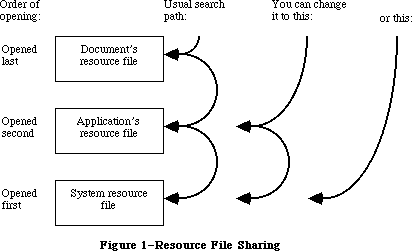 Figure 1–Resource File Searching
_______________________________________________________________________________
»OVERVIEW OF RESOURCE FILES
_______________________________________________________________________________
Resources may be put in a resource file with the aid of the Resource Editor, or with whatever tools are provided by the development system you’re using.
A resource file is not a file in the strictest sense. Although it’s functionally like a file in many ways, it’s actually just one of two parts, or forks, of a file (see Figure 2). Every file has a resource fork and a data fork (either of which may be empty). The resource fork of an application file contains not only the resources used by the application but also the application code itself. The code may be divided into different segments, each of which is a resource; this allows various parts of the program to be loaded and purged dynamically. Information is stored in the resource fork via the Resource Manager. The data fork of an application file can contain anything an application wants to store there. Information is stored in the data fork via the File Manager.
Figure 1–Resource File Searching
_______________________________________________________________________________
»OVERVIEW OF RESOURCE FILES
_______________________________________________________________________________
Resources may be put in a resource file with the aid of the Resource Editor, or with whatever tools are provided by the development system you’re using.
A resource file is not a file in the strictest sense. Although it’s functionally like a file in many ways, it’s actually just one of two parts, or forks, of a file (see Figure 2). Every file has a resource fork and a data fork (either of which may be empty). The resource fork of an application file contains not only the resources used by the application but also the application code itself. The code may be divided into different segments, each of which is a resource; this allows various parts of the program to be loaded and purged dynamically. Information is stored in the resource fork via the Resource Manager. The data fork of an application file can contain anything an application wants to store there. Information is stored in the data fork via the File Manager.
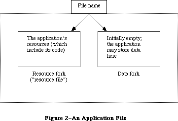 Figure 2–An Application File
As shown in Figure 3, the system resource file has this same structure. The resource fork contains the system resources and the data fork contains “patches” to the routines in the Macintosh ROM. Figure 3 also shows the structure of a file containing a document; the resource fork contains the document’s resources and the data fork contains the data that comprises the document.
To open a resource file, the Resource Manager calls the appropriate File Manager routine and returns the reference number it gets from the File Manager. This is a number greater than 0 by which you can refer to the file when calling other Resource Manager routines.
Note: This reference number is actually the path reference number, as
described in the File Manager chapter.
Most of the Resource Manager routines don’t require the resource file’s reference number as a parameter. Rather, they assume that the current resource file is where they should perform their operation (or begin it, in the case of a search for a resource). The current resource file is the last one that was opened unless you specify otherwise.
Figure 2–An Application File
As shown in Figure 3, the system resource file has this same structure. The resource fork contains the system resources and the data fork contains “patches” to the routines in the Macintosh ROM. Figure 3 also shows the structure of a file containing a document; the resource fork contains the document’s resources and the data fork contains the data that comprises the document.
To open a resource file, the Resource Manager calls the appropriate File Manager routine and returns the reference number it gets from the File Manager. This is a number greater than 0 by which you can refer to the file when calling other Resource Manager routines.
Note: This reference number is actually the path reference number, as
described in the File Manager chapter.
Most of the Resource Manager routines don’t require the resource file’s reference number as a parameter. Rather, they assume that the current resource file is where they should perform their operation (or begin it, in the case of a search for a resource). The current resource file is the last one that was opened unless you specify otherwise.
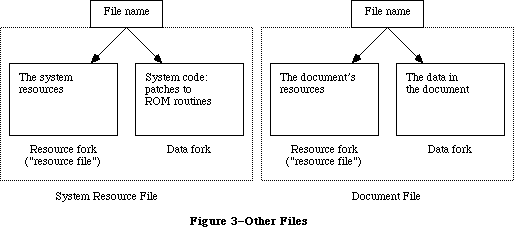 Figure 3–Other Files
A resource file consists primarily of resource data and a resource map. The resource data consists of the resources themselves (for example, the bit image for an icon or the title and commands for a menu). The resource map contains an entry for each resource that provides the location of its resource data. Each entry in the map either gives the offset of the resource data in the file or contains a handle to the data if it’s in memory. The resource map is like the index of a book; the Resource Manager looks in it for the resource you specify and determines where its resource data is located.
The resource map is read into memory when the file is opened and remains there until the file is closed. Although for simplicity we say that the Resource Manager searches resource files, it actually searches the resource maps that were read into memory, and not the resource files on the disk.
Resource data is normally read into memory when needed, though you can specify that it be read in as soon as the resource file is opened. When read in, resource data is stored in a relocatable block in the heap. Resources are designated in the resource map as being either purgeable or unpurgeable; if purgeable, they may be removed from the heap when space is required by the Memory Manager. Resources consisting of a relatively large amount of data are usually designated as purgeable. Before accessing such a resource through its handle, you ask the Resource Manager to read the resource into memory again if it has been purged.
Note: Programmers concerned about the amount of available memory should be
aware that there’s a 12-byte overhead in the resource map for every
resource and an additional 12-byte overhead for memory management if
the resource is read into memory.
To modify a resource, you change the resource data or resource map in memory. The change becomes permanent only at your explicit request, and then only when the application terminates or when you call a routine specifically for updating or closing the resource file.
Each resource file also may contain up to 128 bytes of any data the application wants to store there.
_______________________________________________________________________________
»RESOURCE SPECIFICATION
_______________________________________________________________________________
In a resource file, every resource is assigned a type, an ID number, and optionally a name. When calling a Resource Manager routine to access a resource, you specify the resource by passing its type and either its ID number or its name. This section gives some general information about resource specification.
_______________________________________________________________________________
»Resource Types
The resource type is a sequence of any four characters (printing or
nonprinting). Its Pascal data type is:
TYPE ResType = PACKED ARRAY[1..4] OF CHAR;
The following standard resource types have been defined (System file 4.1 or later). All-uppercase resource types are listed first.
Resource Meaning
type
'ALRT' Alert template
'ADBS' Apple Desktop Bus service routine
'BNDL' Bundle
'CACH' RAM cache code
'CDEF' Control definition function
'CNTL' Control template
'CODE' Application code segment
'CURS' Cursor
'DITL' Item list in a dialog or alert
'DLOG' Dialog template
'DRVR' Desk accessory or other device driver
'DSAT' System startup alert table
'FKEY' Command-Shift-number routine
'FMTR' 3 1/2-inch disk formatting code
'FOND' Font family record
'FONT' Font
'FREF' File reference
'FRSV' IDs of fonts reserved for system use
'FWID' Font widths
'ICN#' Icon list
'ICON' Icon
'INIT' Initialization resource
'INTL' International resource
'INT#' List of integers owned by Find File
'KCAP' Physical layout of keyboard (used by Key Caps desk accessory)
'KCHR' ASCII mapping (software)
'KMAP' Keyboard mapping (hardware)
'KSWP' Keyboard script table
'LDEF' List definition procedure
'MBAR' Menu bar
'MBDF' Default menu definition procedure
'MDEF' Menu definition procedure
'MENU' Menu
'MMAP' Mouse tracking code
'NBPC' Appletalk bundle
'NFNT' 128K ROM font
'PACK' Package
'PAT ' Pattern (The space is required.)
'PAT#' Pattern list
'PDEF' Printing code
'PICT' Picture
'PREC' Print record
'PRER' Device type for Chooser
'PRES' Device type for Chooser
'PTCH' ROM patch code
'RDEV' Device type for Chooser
'ROvr' Code for overriding ROM resources
'ROv#' List of ROM resources to override
'SERD' RAM Serial Driver
'SICN' Script symbol
'STR ' String (The space is required.)
'STR#' String list
'WDEF' Window definition function
'WIND' Window template
'actb' Alert color table
'atpl' Internal AppleTalk resource
'bmap' Bit maps used by the Control Panel
'boot' Copy of boot blocks
'cctb' Control color table
'cicn' Color Macintosh icon
'clst' Cached icon lists used by Chooser and Control Panel
'clut' Color look-up table
'crsr' Color cursor
'ctab' Used by the Control Panel
'dctb' Dialog color table
'fctb' Font color table
'finf' Font information
'gama' Color correction table
'ictb' Color table dialog item
'insc' Installer script
'itl0' Date and time formats
'itl1' Names of days and months
'itl2' International Utilities Package sort hooks
'itlb' International Utilities Package script bundles
'itlc' International configuration for Script Manager
'lmem' Low memory globals
'mcky' Mouse tracking
'mctb' Menu color information table
'mitq' Internal memory requirements for MakeITable
'mppc' AppleTalk configuration code
'nrct' Rectangle positions
'pltt' Color palette
'ppat' Pixel pattern
'snd ' Sound (The space is required.)
'snth' Synthesizer
'wctb' Window color table
Uppercase and lowercase letters are distinguished in resource types. You can use any four-character sequence, except those listed above, and those sequences consisting entirely of lowercase letters (reserved by Apple), for resource types specific to your application. There’s no need to register your resource types with Apple since they’ll only be used by your application.
_______________________________________________________________________________
»Resource ID Numbers
Every resource has an ID number, or resource ID. The resource ID should be unique within each resource type, but resources of different types may have the same ID. If you assign the same resource ID to two resources of the same type, the second assignment of the ID will override the first, thereby making the first resource inaccessible by ID.
Warning: Certain resources contain the resource IDs of other resources; for
instance, a dialog template contains the resource ID of its item
list. In order not to duplicate an existing resource ID, a program
that copies resources may need to change the resource ID of a
resource; such a program may not, however, change the ID where it
is referred to by other resources. For instance, an item list’s
resource ID contained in a dialog template may not be changed,
even though the actual resource ID of the item list was changed to
avoid duplication; this would make it impossible for the template
to access the item list. Be sure to verify, and if necessary correct,
the IDs contained within such resources. (For related information,
see the section “Resource IDs of Owned Resources” below.)
By convention, the ID numbers are divided into the following ranges:
Range Description
–32768 through –16385 Reserved; do not use
–16384 through –1 Used for system resources owned by other system
resources (explained below)
0 through 127 Used for other system resources
128 through 32767 Available for your use in whatever way you wish
Note: The chapters that describe the different types of resources in detail
give information about resource types that may be more restrictive
about the allowable range for their resource IDs. A device driver,
for instance, can’t have a resource ID greater than 31.
Resource IDs of Owned Resources
This section is intended for advanced programmers who are writing their own desk accessories (or other drivers), or special types of windows, controls, and menus. It’s also useful in understanding the way that resource-copying programs recognize resources that are associated with each other.
Certain types of system resources may have resources of their own in the system resource file; the “owning” resource consists of code that reads the “owned” resource into memory. For example, a desk accessory might have its own pattern and string resources. A special numbering convention is used to associate owned system resources with the resources they belong to. This enables resource-copying programs to recognize which additional resources need to be copied along with an owning resource. An owned system resource has the ID illustrated in Figure 4.
Figure 3–Other Files
A resource file consists primarily of resource data and a resource map. The resource data consists of the resources themselves (for example, the bit image for an icon or the title and commands for a menu). The resource map contains an entry for each resource that provides the location of its resource data. Each entry in the map either gives the offset of the resource data in the file or contains a handle to the data if it’s in memory. The resource map is like the index of a book; the Resource Manager looks in it for the resource you specify and determines where its resource data is located.
The resource map is read into memory when the file is opened and remains there until the file is closed. Although for simplicity we say that the Resource Manager searches resource files, it actually searches the resource maps that were read into memory, and not the resource files on the disk.
Resource data is normally read into memory when needed, though you can specify that it be read in as soon as the resource file is opened. When read in, resource data is stored in a relocatable block in the heap. Resources are designated in the resource map as being either purgeable or unpurgeable; if purgeable, they may be removed from the heap when space is required by the Memory Manager. Resources consisting of a relatively large amount of data are usually designated as purgeable. Before accessing such a resource through its handle, you ask the Resource Manager to read the resource into memory again if it has been purged.
Note: Programmers concerned about the amount of available memory should be
aware that there’s a 12-byte overhead in the resource map for every
resource and an additional 12-byte overhead for memory management if
the resource is read into memory.
To modify a resource, you change the resource data or resource map in memory. The change becomes permanent only at your explicit request, and then only when the application terminates or when you call a routine specifically for updating or closing the resource file.
Each resource file also may contain up to 128 bytes of any data the application wants to store there.
_______________________________________________________________________________
»RESOURCE SPECIFICATION
_______________________________________________________________________________
In a resource file, every resource is assigned a type, an ID number, and optionally a name. When calling a Resource Manager routine to access a resource, you specify the resource by passing its type and either its ID number or its name. This section gives some general information about resource specification.
_______________________________________________________________________________
»Resource Types
The resource type is a sequence of any four characters (printing or
nonprinting). Its Pascal data type is:
TYPE ResType = PACKED ARRAY[1..4] OF CHAR;
The following standard resource types have been defined (System file 4.1 or later). All-uppercase resource types are listed first.
Resource Meaning
type
'ALRT' Alert template
'ADBS' Apple Desktop Bus service routine
'BNDL' Bundle
'CACH' RAM cache code
'CDEF' Control definition function
'CNTL' Control template
'CODE' Application code segment
'CURS' Cursor
'DITL' Item list in a dialog or alert
'DLOG' Dialog template
'DRVR' Desk accessory or other device driver
'DSAT' System startup alert table
'FKEY' Command-Shift-number routine
'FMTR' 3 1/2-inch disk formatting code
'FOND' Font family record
'FONT' Font
'FREF' File reference
'FRSV' IDs of fonts reserved for system use
'FWID' Font widths
'ICN#' Icon list
'ICON' Icon
'INIT' Initialization resource
'INTL' International resource
'INT#' List of integers owned by Find File
'KCAP' Physical layout of keyboard (used by Key Caps desk accessory)
'KCHR' ASCII mapping (software)
'KMAP' Keyboard mapping (hardware)
'KSWP' Keyboard script table
'LDEF' List definition procedure
'MBAR' Menu bar
'MBDF' Default menu definition procedure
'MDEF' Menu definition procedure
'MENU' Menu
'MMAP' Mouse tracking code
'NBPC' Appletalk bundle
'NFNT' 128K ROM font
'PACK' Package
'PAT ' Pattern (The space is required.)
'PAT#' Pattern list
'PDEF' Printing code
'PICT' Picture
'PREC' Print record
'PRER' Device type for Chooser
'PRES' Device type for Chooser
'PTCH' ROM patch code
'RDEV' Device type for Chooser
'ROvr' Code for overriding ROM resources
'ROv#' List of ROM resources to override
'SERD' RAM Serial Driver
'SICN' Script symbol
'STR ' String (The space is required.)
'STR#' String list
'WDEF' Window definition function
'WIND' Window template
'actb' Alert color table
'atpl' Internal AppleTalk resource
'bmap' Bit maps used by the Control Panel
'boot' Copy of boot blocks
'cctb' Control color table
'cicn' Color Macintosh icon
'clst' Cached icon lists used by Chooser and Control Panel
'clut' Color look-up table
'crsr' Color cursor
'ctab' Used by the Control Panel
'dctb' Dialog color table
'fctb' Font color table
'finf' Font information
'gama' Color correction table
'ictb' Color table dialog item
'insc' Installer script
'itl0' Date and time formats
'itl1' Names of days and months
'itl2' International Utilities Package sort hooks
'itlb' International Utilities Package script bundles
'itlc' International configuration for Script Manager
'lmem' Low memory globals
'mcky' Mouse tracking
'mctb' Menu color information table
'mitq' Internal memory requirements for MakeITable
'mppc' AppleTalk configuration code
'nrct' Rectangle positions
'pltt' Color palette
'ppat' Pixel pattern
'snd ' Sound (The space is required.)
'snth' Synthesizer
'wctb' Window color table
Uppercase and lowercase letters are distinguished in resource types. You can use any four-character sequence, except those listed above, and those sequences consisting entirely of lowercase letters (reserved by Apple), for resource types specific to your application. There’s no need to register your resource types with Apple since they’ll only be used by your application.
_______________________________________________________________________________
»Resource ID Numbers
Every resource has an ID number, or resource ID. The resource ID should be unique within each resource type, but resources of different types may have the same ID. If you assign the same resource ID to two resources of the same type, the second assignment of the ID will override the first, thereby making the first resource inaccessible by ID.
Warning: Certain resources contain the resource IDs of other resources; for
instance, a dialog template contains the resource ID of its item
list. In order not to duplicate an existing resource ID, a program
that copies resources may need to change the resource ID of a
resource; such a program may not, however, change the ID where it
is referred to by other resources. For instance, an item list’s
resource ID contained in a dialog template may not be changed,
even though the actual resource ID of the item list was changed to
avoid duplication; this would make it impossible for the template
to access the item list. Be sure to verify, and if necessary correct,
the IDs contained within such resources. (For related information,
see the section “Resource IDs of Owned Resources” below.)
By convention, the ID numbers are divided into the following ranges:
Range Description
–32768 through –16385 Reserved; do not use
–16384 through –1 Used for system resources owned by other system
resources (explained below)
0 through 127 Used for other system resources
128 through 32767 Available for your use in whatever way you wish
Note: The chapters that describe the different types of resources in detail
give information about resource types that may be more restrictive
about the allowable range for their resource IDs. A device driver,
for instance, can’t have a resource ID greater than 31.
Resource IDs of Owned Resources
This section is intended for advanced programmers who are writing their own desk accessories (or other drivers), or special types of windows, controls, and menus. It’s also useful in understanding the way that resource-copying programs recognize resources that are associated with each other.
Certain types of system resources may have resources of their own in the system resource file; the “owning” resource consists of code that reads the “owned” resource into memory. For example, a desk accessory might have its own pattern and string resources. A special numbering convention is used to associate owned system resources with the resources they belong to. This enables resource-copying programs to recognize which additional resources need to be copied along with an owning resource. An owned system resource has the ID illustrated in Figure 4.
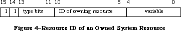 Figure 4–Resource ID of an Owned System Resource
Bits 14 and 15 are always 1. Bits 11-13 specify the type of the owning resource, as follows:
Type bits Type
000 'DRVR'
001 'WDEF'
010 'MDEF'
011 'CDEF'
100 'PDEF'
101 'PACK'
110 Reserved for future use
111 Reserved for future use
Bits 5-10 contain the resource ID of the owning resource (limited to 0 through 63). Bits 0-4 contain any desired value (0 through 31).
Certain types of resources can’t be owned, because their IDs don’t conform to the special numbering convention described above. For instance, while a resource of type 'WDEF' can own other resources, it cannot itself be owned since its resource ID can’t be more than 12 bits long (as described in the Window Manager chapter). Fonts are also an exception because their IDs include the font size. The chapters describing the different types of resources provide detailed information about such restrictions.
An owned resource may itself contain the ID of a resource associated with it. For instance, a dialog template owned by a desk accessory contains the resource ID of its item list. Though the item list is associated with the dialog template, it’s actually owned (indirectly) by the desk accessory. The resource ID of the item list should conform to the same special convention as the ID of the template. For example, if the resource ID of the desk accessory is 17, the IDs of both the template and the item list should contain the value 17 in bits 5-10.
X-Ref: Technical Note #6
As mentioned above, a program that copies resources may need to change the resource ID of a resource in order not to duplicate an existing resource ID. Bits 5-10 of resources owned, directly or indirectly, by the copied resource will also be changed when those resources are copied. For instance, in the above example, if the desk accessory must be given a new ID, bits 5-10 of both the template and the item list will also be changed.
Warning: Remember that while the ID of an owned resource may be changed by a
resource-copying program, the ID may not be changed where it appears
in other resources (such as an item list’s ID contained in a dialog
template).
_______________________________________________________________________________
»Resource Names
A resource may optionally have a resource name. Like the resource ID, the resource name should be unique within each type; if you assign the same resource name to two resources of the same type, the second assignment of the name will override the first, thereby making the first resource inaccessible by name. When comparing resource names, the Resource Manager ignores case (but does not ignore diacritical marks).
_______________________________________________________________________________
»Resource References
The entries in the resource map that identify and locate the resources in a resource file are known as resource references. Using the analogy of an index of a book, resource references are like the individual entries in the index
(see Figure 5).
Every resource reference includes the type, ID number, and optional name of the resource. Suppose you’re accessing a resource for the first time. You pass a resource specification to the Resource Manager, which looks for a match among all the references in the resource map of the current resource file. If none is found, it looks at the references in the resource map of the next resource file to be searched. (Remember, it looks in the resource map in memory, not in the file.) Eventually it finds a reference matching the specification, which tells it where the resource data is in the file. After reading the resource data into memory, the Resource Manager stores a handle to that data in the reference
(again, in the resource map in memory) and returns the handle so you can use it to refer to the resource in subsequent routine calls.
Figure 4–Resource ID of an Owned System Resource
Bits 14 and 15 are always 1. Bits 11-13 specify the type of the owning resource, as follows:
Type bits Type
000 'DRVR'
001 'WDEF'
010 'MDEF'
011 'CDEF'
100 'PDEF'
101 'PACK'
110 Reserved for future use
111 Reserved for future use
Bits 5-10 contain the resource ID of the owning resource (limited to 0 through 63). Bits 0-4 contain any desired value (0 through 31).
Certain types of resources can’t be owned, because their IDs don’t conform to the special numbering convention described above. For instance, while a resource of type 'WDEF' can own other resources, it cannot itself be owned since its resource ID can’t be more than 12 bits long (as described in the Window Manager chapter). Fonts are also an exception because their IDs include the font size. The chapters describing the different types of resources provide detailed information about such restrictions.
An owned resource may itself contain the ID of a resource associated with it. For instance, a dialog template owned by a desk accessory contains the resource ID of its item list. Though the item list is associated with the dialog template, it’s actually owned (indirectly) by the desk accessory. The resource ID of the item list should conform to the same special convention as the ID of the template. For example, if the resource ID of the desk accessory is 17, the IDs of both the template and the item list should contain the value 17 in bits 5-10.
X-Ref: Technical Note #6
As mentioned above, a program that copies resources may need to change the resource ID of a resource in order not to duplicate an existing resource ID. Bits 5-10 of resources owned, directly or indirectly, by the copied resource will also be changed when those resources are copied. For instance, in the above example, if the desk accessory must be given a new ID, bits 5-10 of both the template and the item list will also be changed.
Warning: Remember that while the ID of an owned resource may be changed by a
resource-copying program, the ID may not be changed where it appears
in other resources (such as an item list’s ID contained in a dialog
template).
_______________________________________________________________________________
»Resource Names
A resource may optionally have a resource name. Like the resource ID, the resource name should be unique within each type; if you assign the same resource name to two resources of the same type, the second assignment of the name will override the first, thereby making the first resource inaccessible by name. When comparing resource names, the Resource Manager ignores case (but does not ignore diacritical marks).
_______________________________________________________________________________
»Resource References
The entries in the resource map that identify and locate the resources in a resource file are known as resource references. Using the analogy of an index of a book, resource references are like the individual entries in the index
(see Figure 5).
Every resource reference includes the type, ID number, and optional name of the resource. Suppose you’re accessing a resource for the first time. You pass a resource specification to the Resource Manager, which looks for a match among all the references in the resource map of the current resource file. If none is found, it looks at the references in the resource map of the next resource file to be searched. (Remember, it looks in the resource map in memory, not in the file.) Eventually it finds a reference matching the specification, which tells it where the resource data is in the file. After reading the resource data into memory, the Resource Manager stores a handle to that data in the reference
(again, in the resource map in memory) and returns the handle so you can use it to refer to the resource in subsequent routine calls.
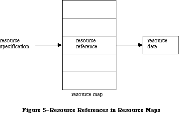 Figure 5–Resource References in Resource Maps
Every resource reference also contains certain resource attributes that determine how the resource should be dealt with. In the routine calls for setting or reading them, each attribute is specified by a bit in the low-order byte of a word, as illustrated in Figure 6.
Figure 5–Resource References in Resource Maps
Every resource reference also contains certain resource attributes that determine how the resource should be dealt with. In the routine calls for setting or reading them, each attribute is specified by a bit in the low-order byte of a word, as illustrated in Figure 6.
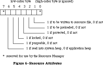 Figure 6–Resource Attributes
The Resource Manager provides a predefined constant for each attribute, in which the bit corresponding to that attribute is set.
CONST resSysHeap = 64; {set if read into system heap}
resPurgeable = 32; {set if purgeable}
resLocked = 16; {set if locked}
resProtected = 8; {set if protected}
resPreload = 4; {set if to be preloaded}
resChanged = 2; {set if to be written to resource file}
Warning: Your application should not change the setting of bit 0 or 7, nor
should it set the resChanged attribute directly. (ResChanged is set
as a side effect of the procedure you call to tell the Resource
Manager that you’ve changed a resource.)
The resSysHeap attribute should not be set for your application’s resources. If a resource with this attribute set is too large for the system heap, the bit will be cleared, and the resource will be read into the application heap.
Since a locked resource is neither relocatable nor purgeable, the resLocked attribute overrides the resPurgeable attribute; when resLocked is set, the resource will not be purgeable regardless of whether resPurgeable is set.
If the resProtected attribute is set, the application can’t use Resource Manager routines to change the ID number or name of the resource, modify its contents, or remove the resource from the resource file. The routine that sets the resource attributes may be called, however, to remove the protection or just change some of the other attributes.
The resPreload attribute tells the Resource Manager to read this resource into memory immediately after opening the resource file. This is useful, for example, if you immediately want to draw ten icons stored in the file; rather than read and draw each one individually in turn, you can have all of them read in when the file is opened and just draw all ten.
The resChanged attribute is used only while the resource map is in memory; it must be 0 in the resource file. It tells the Resource Manager whether this resource has been changed.
_______________________________________________________________________________
»RESOURCES IN ROM
_______________________________________________________________________________
The information presented in this section is useful only to assembly-language programmers.
With the 64K ROM, many of the system resources are stored in the system resource file. With the 128K ROM, the following system resources are stored in ROM:
Type ID Description
'CURS' 1 IBeamCursor
'CURS' 2 CrossCursor
'CURS' 3 PlusCursor
'CURS' 4 WatchCursor
'DRVR' 2 Printer Driver shell (.Print)
'DRVR' 3 Sound Driver (.Sound)
'DRVR' 4 Disk Driver (.Sony)
'DRVR' 9 AppleTalk driver (.MPP)
'DRVR' A AppleTalk driver (.ATP)
'FONT' 0 Name of system font
'FONT' C System font
'MDEF' 0 Default menu definition procedure
'PACK' 4 Floating-Point Arithmetic Package
'PACK' 5 Transcendental Functions Package
'PACK' 7 Binary-Decimal Conversion Package
'SERD' 0 Serial Driver
'WDEF' 0 Default window definition function
Note: The Sound Driver, Disk Driver, and Serial Driver are in the 64K ROM,
but are not stored as resources.
Certain system resources were placed in the 128K ROM for quick access. The Macintosh SE and Macintosh II ROMs include additional resources in ROM; they’re outlined below.
The following system resources are stored in the Macintosh SE ROM (the resource IDs are in hexadecimal):
Type ID Description
'CDEF' 0 Default button definition procedure
'CDEF' 1 Default scroll bar definition procedure
'CURS' 1 IBeamCursor
'CURS' 2 CrossCursor
'CURS' 3 PlusCursor
'CURS' 4 WatchCursor
'DRVR' 3 Sound Driver (.Sound)
'DRVR' 4 Disk Driver (.Sony)
'DRVR' 9 AppleTalk driver (.MPP)
'DRVR' A AppleTalk driver (.ATP)
'DRVR' 28 AppleTalk driver (.XPP)
'FONT' 0 Name of system font
'FONT' C System font (Chicago 12)
'FONT' 189 Geneva 9 font
'FONT' 18C Geneva 12 font
'FONT' 209 Monaco 9 font
'KMAP' 0 Keyboard map for keyboard driver
'MBDF' 0 Default menu bar procedure
'MDEF' 0 Default menu definition procedure
'PACK' 4 Floating-Point Arithmetic Package
'PACK' 5 Transcendental Functions Package
'PACK' 7 Binary-Decimal Conversion Package
'SERD' 0 Serial Driver
'WDEF' 0 Default window definition function (document window)
'WDEF' 1 Default window definition function (rounded window)
The following system resources are stored in the Macintosh II ROM (the resource IDs are in hexadecimal):
Type ID Description
'CDEF' 0 Default button definition procedure
'CDEF' 1 Default scroll bar definition procedure
'CURS' 1 IBeamCursor
'CURS' 2 CrossCursor
'CURS' 3 PlusCursor
'CURS' 4 WatchCursor
'DRVR' 3 Sound Driver (.Sound)
'DRVR' 4 Disk Driver (.Sony)
'DRVR' 9 AppleTalk driver (.MPP)
'DRVR' A AppleTalk driver (.ATP)
'DRVR' 28 AppleTalk driver (.XPP)
'FONT' 0 Name of system font
'FONT' C System font (Chicago 12)
'FONT' 180 Name of Geneva font
'FONT' 189 Geneva 9 font
'FONT' 18C Geneva 12 font
'FONT' 200 Name of Monaco font
'FONT' 209 Monaco 9 font
'KCHR' 0 ASCII mapping (software)
'KMAP' 0 Keyboard mapping (hardware)
'MBDF' 0 Default menu bar procedure
'MDEF' 0 Default menu definition procedure
'NFNT' 2 Chicago 12 font (4-bit)
'NFNT' 3 Chicago 12 font (8-bit)
'NFNT' 22 Geneva 9 font (4-bit)
'PACK' 4 Floating-Point Arithmetic Package
'PACK' 5 Transcendental Functions Package
'PACK' 7 Binary-Decimal Conversion Package
'SERD' 0 Serial Driver
'WDEF' 0 Default window definition function (document window)
'WDEF' 1 Default window definition function (rounded window)
'cctb' 0 Control color table
'clut' 1 Color look-up table
'clut' 2 Color look-up table
'clut' 4 Color look-up table
'clut' 8 Color look-up table
'clut' 7F Color look-up table
'gama' 0 Color correction table
'mitq' 0 Internal memory requirements for MakeITable
'snd ' 1 Brass horn
'wctb' 0 Window color table
When the Macintosh is turned on, a call is made to the InitResources function. The Resource Manager creates a special heap zone within the system heap, and builds a resource map that points to the ROM resources.
In order to use the ROM resources in your calls to the Resource Manager, the ROM map must be inserted in front of the map for the system resource file prior to making the call. The global variable RomMapInsert is used for this purpose; it tells the Resource Manager to insert the ROM map for the next call only. An adjacent global variable, TmpResLoad, is also useful; when RomMapInsert is TRUE, TmpResLoad determines whether the value of the global variable ResLoad is taken to be TRUE or FALSE (overriding the actual value of ResLoad) for the next call only. Figure 7 shows these two variables.
Figure 6–Resource Attributes
The Resource Manager provides a predefined constant for each attribute, in which the bit corresponding to that attribute is set.
CONST resSysHeap = 64; {set if read into system heap}
resPurgeable = 32; {set if purgeable}
resLocked = 16; {set if locked}
resProtected = 8; {set if protected}
resPreload = 4; {set if to be preloaded}
resChanged = 2; {set if to be written to resource file}
Warning: Your application should not change the setting of bit 0 or 7, nor
should it set the resChanged attribute directly. (ResChanged is set
as a side effect of the procedure you call to tell the Resource
Manager that you’ve changed a resource.)
The resSysHeap attribute should not be set for your application’s resources. If a resource with this attribute set is too large for the system heap, the bit will be cleared, and the resource will be read into the application heap.
Since a locked resource is neither relocatable nor purgeable, the resLocked attribute overrides the resPurgeable attribute; when resLocked is set, the resource will not be purgeable regardless of whether resPurgeable is set.
If the resProtected attribute is set, the application can’t use Resource Manager routines to change the ID number or name of the resource, modify its contents, or remove the resource from the resource file. The routine that sets the resource attributes may be called, however, to remove the protection or just change some of the other attributes.
The resPreload attribute tells the Resource Manager to read this resource into memory immediately after opening the resource file. This is useful, for example, if you immediately want to draw ten icons stored in the file; rather than read and draw each one individually in turn, you can have all of them read in when the file is opened and just draw all ten.
The resChanged attribute is used only while the resource map is in memory; it must be 0 in the resource file. It tells the Resource Manager whether this resource has been changed.
_______________________________________________________________________________
»RESOURCES IN ROM
_______________________________________________________________________________
The information presented in this section is useful only to assembly-language programmers.
With the 64K ROM, many of the system resources are stored in the system resource file. With the 128K ROM, the following system resources are stored in ROM:
Type ID Description
'CURS' 1 IBeamCursor
'CURS' 2 CrossCursor
'CURS' 3 PlusCursor
'CURS' 4 WatchCursor
'DRVR' 2 Printer Driver shell (.Print)
'DRVR' 3 Sound Driver (.Sound)
'DRVR' 4 Disk Driver (.Sony)
'DRVR' 9 AppleTalk driver (.MPP)
'DRVR' A AppleTalk driver (.ATP)
'FONT' 0 Name of system font
'FONT' C System font
'MDEF' 0 Default menu definition procedure
'PACK' 4 Floating-Point Arithmetic Package
'PACK' 5 Transcendental Functions Package
'PACK' 7 Binary-Decimal Conversion Package
'SERD' 0 Serial Driver
'WDEF' 0 Default window definition function
Note: The Sound Driver, Disk Driver, and Serial Driver are in the 64K ROM,
but are not stored as resources.
Certain system resources were placed in the 128K ROM for quick access. The Macintosh SE and Macintosh II ROMs include additional resources in ROM; they’re outlined below.
The following system resources are stored in the Macintosh SE ROM (the resource IDs are in hexadecimal):
Type ID Description
'CDEF' 0 Default button definition procedure
'CDEF' 1 Default scroll bar definition procedure
'CURS' 1 IBeamCursor
'CURS' 2 CrossCursor
'CURS' 3 PlusCursor
'CURS' 4 WatchCursor
'DRVR' 3 Sound Driver (.Sound)
'DRVR' 4 Disk Driver (.Sony)
'DRVR' 9 AppleTalk driver (.MPP)
'DRVR' A AppleTalk driver (.ATP)
'DRVR' 28 AppleTalk driver (.XPP)
'FONT' 0 Name of system font
'FONT' C System font (Chicago 12)
'FONT' 189 Geneva 9 font
'FONT' 18C Geneva 12 font
'FONT' 209 Monaco 9 font
'KMAP' 0 Keyboard map for keyboard driver
'MBDF' 0 Default menu bar procedure
'MDEF' 0 Default menu definition procedure
'PACK' 4 Floating-Point Arithmetic Package
'PACK' 5 Transcendental Functions Package
'PACK' 7 Binary-Decimal Conversion Package
'SERD' 0 Serial Driver
'WDEF' 0 Default window definition function (document window)
'WDEF' 1 Default window definition function (rounded window)
The following system resources are stored in the Macintosh II ROM (the resource IDs are in hexadecimal):
Type ID Description
'CDEF' 0 Default button definition procedure
'CDEF' 1 Default scroll bar definition procedure
'CURS' 1 IBeamCursor
'CURS' 2 CrossCursor
'CURS' 3 PlusCursor
'CURS' 4 WatchCursor
'DRVR' 3 Sound Driver (.Sound)
'DRVR' 4 Disk Driver (.Sony)
'DRVR' 9 AppleTalk driver (.MPP)
'DRVR' A AppleTalk driver (.ATP)
'DRVR' 28 AppleTalk driver (.XPP)
'FONT' 0 Name of system font
'FONT' C System font (Chicago 12)
'FONT' 180 Name of Geneva font
'FONT' 189 Geneva 9 font
'FONT' 18C Geneva 12 font
'FONT' 200 Name of Monaco font
'FONT' 209 Monaco 9 font
'KCHR' 0 ASCII mapping (software)
'KMAP' 0 Keyboard mapping (hardware)
'MBDF' 0 Default menu bar procedure
'MDEF' 0 Default menu definition procedure
'NFNT' 2 Chicago 12 font (4-bit)
'NFNT' 3 Chicago 12 font (8-bit)
'NFNT' 22 Geneva 9 font (4-bit)
'PACK' 4 Floating-Point Arithmetic Package
'PACK' 5 Transcendental Functions Package
'PACK' 7 Binary-Decimal Conversion Package
'SERD' 0 Serial Driver
'WDEF' 0 Default window definition function (document window)
'WDEF' 1 Default window definition function (rounded window)
'cctb' 0 Control color table
'clut' 1 Color look-up table
'clut' 2 Color look-up table
'clut' 4 Color look-up table
'clut' 8 Color look-up table
'clut' 7F Color look-up table
'gama' 0 Color correction table
'mitq' 0 Internal memory requirements for MakeITable
'snd ' 1 Brass horn
'wctb' 0 Window color table
When the Macintosh is turned on, a call is made to the InitResources function. The Resource Manager creates a special heap zone within the system heap, and builds a resource map that points to the ROM resources.
In order to use the ROM resources in your calls to the Resource Manager, the ROM map must be inserted in front of the map for the system resource file prior to making the call. The global variable RomMapInsert is used for this purpose; it tells the Resource Manager to insert the ROM map for the next call only. An adjacent global variable, TmpResLoad, is also useful; when RomMapInsert is TRUE, TmpResLoad determines whether the value of the global variable ResLoad is taken to be TRUE or FALSE (overriding the actual value of ResLoad) for the next call only. Figure 7 shows these two variables.
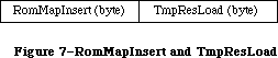 Figure 7–RomMapInsert and TmpResLoad
Two global constants, each a word in length, are provided for setting these variables in tandem: mapTrue inserts the ROM map with SetResLoad(TRUE) and mapFalse inserts the ROM map with SetResLoad(FALSE). As noted, both RomMapInsert and TmpResLoad are cleared after each Resource Manager call.
Note: There is no real resource file associated with the ROM resources; the
ROM map has a path reference number of 1 (an illegal path reference
number). There are two ways to determine if a handle references a ROM
resource. First, you can set up TmpResLoad and RomMapInsert and call
HomeResFile; if 1 is returned, the handle is to a ROM resource. Second,
you can dereference the handle and see if the master pointer points
into the ROM space by comparing it to the global variable ROMBase.
To use the ROM resources in your calls to the Resource Manager, the ROM map must be inserted in front of the map for the System Resource File prior to making the call. Unless the ROM map is inserted, the GetResource call will not search the ROM resources. Sometimes, however, you’ll first want to try to get the resource from any open resource files, and then if it’s not found, to get it from ROM. A new routine, RGetResource, lets you do this easily. It searches the chain of open resource files (including the System Resource File) for the given resource; if it’s not there, it looks in ROM.
_______________________________________________________________________________
»Overriding ROM Resources
This section explains how to override ROM resources.
Warning: As with intercepting system traps using the SetTrapAddress procedure,
you should override ROM resources only if it’s absolutely necessary
and you understand the situation completely.
You can override some of the ROM resources, such as 'CURS' resources, simply by putting the substitute resource in your application’s resource fork. Other ROM resources however, such 'DRVR' and 'PACK' resources, cannot be overridden in this way because they are already referenced and in use when your application is launched.
Whenever InitResource is called, the ROM map is rebuilt. (Do not use InitResources to rebuild the ROM map.) Each time the ROM map is rebuilt, the Resource Manager looks in the system resource file for a 'ROvr' resource 0. If it finds such a resource, it loads it into memory and jumps to this resource via a JSR instruction. The code in the 'ROvr' resource looks in the system resource file for all resources of type 'ROv#' whose version word matches the version word of the ROM (see Figure 8). For example, to override a resource in the 128K ROM, the version must be $75.
Figure 7–RomMapInsert and TmpResLoad
Two global constants, each a word in length, are provided for setting these variables in tandem: mapTrue inserts the ROM map with SetResLoad(TRUE) and mapFalse inserts the ROM map with SetResLoad(FALSE). As noted, both RomMapInsert and TmpResLoad are cleared after each Resource Manager call.
Note: There is no real resource file associated with the ROM resources; the
ROM map has a path reference number of 1 (an illegal path reference
number). There are two ways to determine if a handle references a ROM
resource. First, you can set up TmpResLoad and RomMapInsert and call
HomeResFile; if 1 is returned, the handle is to a ROM resource. Second,
you can dereference the handle and see if the master pointer points
into the ROM space by comparing it to the global variable ROMBase.
To use the ROM resources in your calls to the Resource Manager, the ROM map must be inserted in front of the map for the System Resource File prior to making the call. Unless the ROM map is inserted, the GetResource call will not search the ROM resources. Sometimes, however, you’ll first want to try to get the resource from any open resource files, and then if it’s not found, to get it from ROM. A new routine, RGetResource, lets you do this easily. It searches the chain of open resource files (including the System Resource File) for the given resource; if it’s not there, it looks in ROM.
_______________________________________________________________________________
»Overriding ROM Resources
This section explains how to override ROM resources.
Warning: As with intercepting system traps using the SetTrapAddress procedure,
you should override ROM resources only if it’s absolutely necessary
and you understand the situation completely.
You can override some of the ROM resources, such as 'CURS' resources, simply by putting the substitute resource in your application’s resource fork. Other ROM resources however, such 'DRVR' and 'PACK' resources, cannot be overridden in this way because they are already referenced and in use when your application is launched.
Whenever InitResource is called, the ROM map is rebuilt. (Do not use InitResources to rebuild the ROM map.) Each time the ROM map is rebuilt, the Resource Manager looks in the system resource file for a 'ROvr' resource 0. If it finds such a resource, it loads it into memory and jumps to this resource via a JSR instruction. The code in the 'ROvr' resource looks in the system resource file for all resources of type 'ROv#' whose version word matches the version word of the ROM (see Figure 8). For example, to override a resource in the 128K ROM, the version must be $75.
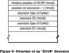 Figure 8–Structure of an 'ROv#' Resource
To override ROM resources in this way, you’ll first need a copy of an 'ROvr' resource; you can obtain one by writing to:
Developer Technical Support
Apple Computer, Inc.
20525 Mariani Avenue, M/S 75-3T
Cupertino, CA 95014
You’ll then need to create an 'ROv#' resource listing the resources you want to override.
_______________________________________________________________________________
»RESOURCES IN THE SYSTEM FILE
_______________________________________________________________________________
The System Resource File contains standard resources that are shared by all applications, and are used by the Macintosh Toolbox and Operating System as well. This file can be modified by the user with the Installer and Font/DA Mover programs.
Warning: Your program should not directly add resources to, or delete
resources from, the System Resource File.
Applications should not alter resources in the System file, except for resources owned by the application, as discussed in the Resource Manager.
With applications that need to install drivers, fonts, or desk accessories, developers should ship an Apple-released copy of the file along with either the Installer and a script (for drivers) or the Font/DA Mover (for fonts and desk accessories).
Note: Some of the resources in the System Resource File are also contained
in the 128K and 256K ROMs; they’re duplicated in the System Resource
File for compatibility with machines in which these resources are not
in ROM.
The rest of this section presents an overview of the System Resource File’s resources, grouped by function.
_______________________________________________________________________________
»Packages
The System Resource File contains the standard Macintosh packages and the resources they use (or own):
• the List Manager Package ('PACK' resource 0), and the standard list
definition procedure ('LDEF' resource 0)
• the Disk Initialization Package ('PACK' resource 2), and code (resource
type 'FMTR') used in formatting disks
• the Standard File Package ('PACK' resource 3), and resources used to
create its alerts and dialogs (resource types 'ALRT', 'DITL', and 'DLOG')
• the Floating-Point Arithmetic Package ('PACK' resource 4)
• the Transcendental Functions Package ('PACK' resource 5)
• the International Utilities Package ('PACK' resource 6)
• the Binary-Decimal Conversion Package ('PACK' resource 7)
• the Color Picker Package ('PACK' resource 12)
_______________________________________________________________________________
»Drivers and Desk Accessories
Certain device drivers (including desk accessories) and the resources they use or own are found in the System Resource File; these resources include
• the .PRINT driver ('DRVR' resource 2) that communicates between the Print
Manager and the printer.
• the .MPP, .ATP, and .XPP drivers ('DRVR' resources 9, 10, and 28
respectively) used by version 42 of AppleTalk.
• the Control Panel desk accessory ('DRVR' resource 18) and the resources
used in displaying its various options. The Control Panel also uses a
resource of type 'clst' to list the cached icons of the devices in order
to improve performance.
• the Chooser desk accessory, which uses the same class of resources as the
Control Panel, including its own 'clst'.
_______________________________________________________________________________
»Patches
For each ROM (64K, 128K, 256K) there are two patch resources of type 'PTCH' that provide updates for ROM routines. At startup, the machine’s ROM is checked and the appropriate 'PTCH' resources are installed and locked in the system heap. The 'PTCH' resources are:
All ROMS 'PTCH' 0
64K ROM 'PTCH' 105
128K ROM 'PTCH' 117
256K ROM (Macintosh SE) 'PTCH' 630
256K ROM (Macintosh II) 'PTCH' 376
_______________________________________________________________________________
»General Resources
Other resources contained in the System Resource File include
• Standard definition procedures for creating windows, menus, controls,
and lists.
• System fonts and font families (resource types 'FONT' and 'FOND').
• System icons.
• The screen utility resources 'FKEY' 3 and 4, which execute a MacPaint
screen snapshot when Command-Shift-3 is pressed, and print a screen
snapshot when Command-Shift-4 is pressed, respectively. Note that
Command-Shift-4 only works with the ImageWriter®; it is useful for a
quick print, but should not be an application’s print strategy.
• Mouse tracking resources: 'mcky' 0 to 4, which provide parameters for
various mouse tracking setups; 'MMAP' 0, which provides mouse tracking
code for use when it is not in ROM.
• Key mapping resources, which implement keyboard mapping in conjunction
with the Apple Desktop Bus: 'ADBS' 2, 'KMAP' 1 and 2, and 'KCHR', which
has IDs for each language. Note that 'INIT' resources 1 and 2, which
used to handle key translation, now point to the 'ADBS'/'KCHR' system
instead.
• Color resources: 'wctb' 0, 'cctb' 0, and 'mitq' 0, which implement color
tables, and 'cicn' 0, the color Macintosh icon. See the Color Quickdraw
and Color Manager chapters for more information.
Notice that some of the resources listed above are “templates”. A template is a list of parameters used to build a Toolbox object; it is not the object itself. For example, a window template contains information specifying the size and location of the window, its title, whether it’s visible, and so on. After the Window Manager has used this information to build the window in memory, the template isn’t needed again until the next window using that template is created.
X-Ref: Technical Note #32
You can use any four-character sequence (except those listed above) for resource types specific to your application.
_______________________________________________________________________________
»USING THE RESOURCE MANAGER
_______________________________________________________________________________
The Resource Manager is initialized automatically when the system starts up: The system resource file is opened and its resource map is read into memory. Your application’s resource file is opened when the application starts up; you can call CurResFile to get its reference number. You can also call OpenResFile to open any resource file that you specify by name, and CloseResFile to close any resource file. A function named ResError lets you check for errors that may occur during execution of Resource Manager routines.
Note: These are the only routines you need to know about to use the Resource
Manager indirectly through other parts of the Toolbox.
Normally when you want to access a resource for the first time, you’ll specify it by type and ID number (or type and name) in a call to GetResource (or GetNamedResource). In special situations, you may want to get every resource of each type. There are two routines which, used together, will tell you all the resource types that are in all open resource files: CountTypes and GetIndType. Similarly, CountResources and GetIndResource may be used to get all resources of a particular type.
If you don’t specify otherwise, GetResource, GetNamedResource, and GetIndResource read the resource data into memory and return a handle to it. Sometimes, however, you may not need the data to be in memory. You can use a procedure named SetResLoad to tell the Resource Manager not to read the resource data into memory when you get a resource; in this case, the handle returned for the resource will be an empty handle (a pointer to a NIL master pointer). You can pass the empty handle to routines that operate only on the resource map (such as the routine that sets resource attributes), since the handle is enough for the Resource Manager to tell what resource you’re referring to. Should you later want to access the resource data, you can read it into memory with the LoadResource procedure. Before calling any of the above routines that read the resource data into memory, it’s a good idea to call SizeResource to see how much space is needed.
Normally the Resource Manager starts looking for a resource in the most recently opened resource file, and searches other open resource files in the reverse of the order that they were opened. In some situations, you may want to change which file is searched first. You can do this with the UseResFile procedure. One such situation might be when you want a resource to be read from the same file as another resource; in this case, you can find out which resource file the other resource was read from by calling the HomeResFile function.
Once you have a handle to a resource, you can call GetResInfo or GetResAttrs to get the information that’s stored for that resource in the resource map, or you can access the resource data through the handle. (If the resource was designated as purgeable, first call LoadResource to ensure that the data is in memory.)
Usually you’ll just read resources from previously created resource files with the routines described above. You may, however, want to modify existing resources or even create your own resource file. To create your own resource file, call CreateResFile (followed by OpenResFile to open it). The AddResource procedure lets you add resources to a resource file; to be sure a new resource won’t override an existing one, you can call the UniqueID function to get an ID number for it. To make a copy of an existing resource, call DetachResource followed by AddResource (with a new resource ID). There are a number of procedures for modifying existing resources:
• To remove a resource, call RmveResource.
• If you’ve changed the resource data for a resource and want the changed
data to be written to the resource file, call ChangedResource; it signals
the Resource Manager to write the data out when the resource file is later
updated.
• To change the information stored for a resource in the resource map, call
SetResInfo or SetResAttrs. If you want the change to be written to the
resource file, call ChangedResource. (Remember that ChangedResource will
also cause the resource data itself to be written out.)
These procedures for adding and modifying resources change only the resource map in memory. The changes are written to the resource file when the application terminates (at which time all resource files other than the system resource file are updated and closed) or when one of the following routines is called:
• CloseResFile, which updates the resource file before closing it
• UpdateResFile, which simply updates the resource file
• WriteResource, which writes the resource data for a specified resource
to the resource file
_______________________________________________________________________________
»RESOURCE MANAGER ROUTINES
_______________________________________________________________________________
Assembly-language note: Except for LoadResource, all Resource Manager routines
preserve all registers except A0 and D0. LoadResource
preserves A0 and D0 as well.
_______________________________________________________________________________
»Initialization
Although you don’t call these initialization routines (because they’re executed automatically for you), it’s a good idea to familiarize yourself with what they do.
FUNCTION InitResources : INTEGER;
InitResources is called by the system when it starts up, and should not be called by the application. It initializes the Resource Manager, opens the system resource file, reads the resource map from the file into memory, and returns a reference number for the file.
Assembly-language note: The name of the system resource file is stored in
the global variable SysResName; the reference number
for the file is stored in the global variable SysMap.
A handle to the resource map of the system resource
file is stored in the variable SysMapHndl.
Note: The application doesn’t need the reference number for the system
resource file, because every Resource Manager routine that has a
reference number as a parameter interprets 0 to mean the system
resource file.
PROCEDURE RsrcZoneInit;
RsrcZoneInit is called automatically when your application starts up, to initialize the resource map read from the system resource file; normally you’ll have no need to call it directly. It “cleans up” after any resource access that may have been done by a previous application. First it closes all open resource files except the system resource file. Then, for every system resource that was read into the application heap (that is, whose resSysHeap attribute is 0), it replaces the handle to that resource in the resource map with NIL. This lets the Resource Manager know that the resource will have to be read in again
(since the previous application heap is no longer around).
_______________________________________________________________________________
»Opening and Closing Resource Files
When calling the CreateResFile or OpenResFile routine, described below, you specify a resource file by its file name; the routine assumes that the file has a version number of 0 and is on the default volume. (Version numbers and volumes are described in the File Manager chapter.) If you want the routine to apply to a file on another volume, just set the default volume to that volume.
X-Ref: Technical Note #101
X-Ref: Technical Note #214
PROCEDURE CreateResFile (fileName: Str255);
CreateResFile creates a resource file containing no resource data. If there’s no file at all with the given name, it also creates an empty data fork for the file. If there’s already a resource file with the given name (that is, a resource fork that isn’t empty), CreateResFile will do nothing and the ResError function will return an appropriate Operating System result code.
Note: Before you can work with the resource file, you need to open it with
OpenResFile.
FUNCTION OpenResFile (fileName: Str255) : INTEGER;
OpenResFile opens the resource file having the given name and makes it the current resource file. It reads the resource map from the file into memory and returns a reference number for the file. It also reads in every resource whose resPreload attribute is set. If the resource file is already open, it doesn’t make it the current resource file; it simply returns the reference number.
Note: You don’t have to call OpenResFile to open the system resource file
or the application’s resource file, because they’re opened when the
system and the application start up, respectively. To get the reference
number of the application’s resource file, you can call CurResFile after
the application starts up (before you open any other resource file).
If the file can’t be opened, OpenResFile will return –1 and the ResError function will return an appropriate Operating System result code. For example, an error occurs if there’s no resource file with the given name.
X-Ref: Technical Note #74
X-Ref: Technical Note #232
Note: To open a resource file simply for block-level operations such as
copying files (without reading the resource map into memory), you
can call the File Manager function OpenRF.
Assembly-language note: A handle to the resource map of the most recently
opened resource file is stored in the global variable
TopMapHndl.
PROCEDURE CloseResFile (refNum: INTEGER);
Given the reference number of a resource file, CloseResFile does the following:
• updates the resource file by calling the UpdateResFile procedure
• for each resource in the resource file, releases the memory it occupies
by calling the ReleaseResource procedure
• releases the memory occupied by the resource map
• closes the resource file
If there’s no resource file open with the given reference number, CloseResFile will do nothing and the ResError function will return the result code resFNotFound. A refNum of 0 represents the system resource file, but if you ask to close this file, CloseResFile first closes all other open resource files.
A CloseResFile of every open resource file (except the system resource file) is done automatically when the application terminates. So you only need to call CloseResFile if you want to close a resource file before the application terminates.
_______________________________________________________________________________
»Checking for Errors
FUNCTION ResError : INTEGER;
Called after one of the various Resource Manager routines that may result in an error condition, ResError returns a result code identifying the error, if any. If no error occurred, it returns the result code
CONST noErr = 0; {no error}
If an error occurred at the Operating System level, it returns an Operating System result code, such as the File Manager “disk I/O” error or the Memory Manager “out of memory” error. (See Appendix A for a list of all result codes.) If an error happened at the Resource Manager level, ResError returns one of the following result codes:
CONST resNotFound = -192; {resource not found}
resFNotFound = -193; {resource file not found}
addResFailed = -194; {AddResource failed}
rmvResFailed = -196; {RmveResource failed}
Each routine description tells which errors may occur for that routine. You can also check for an error after system startup, which calls InitResources, and application startup, which opens the application’s resource file.
Warning: In certain cases, the ResError function will return noError even
though a Resource Manager routine was unable to perform the requested
operation; the routine descriptions give details about the
circumstances under which this will happen.
Assembly-language note: The current value of ResError is stored in the global
variable ResErr. In addition, you can specify a
procedure to be called whenever there’s an error by
storing the address of the procedure in the global
variable ResErrProc (which is normally 0). Before
returning a result code other than noErr, the ResError
function places that result code in register D0 and
calls your procedure.
X-Ref: Technical Note #78
In the 64K ROM, some error conditions resulting from certain Resource Manager routines are not reported by the ResError function. Two additional result codes are defined in the 128K ROM version of the Resource Manager:
CONST resAttrErr = 198; {attribute does not permit operation}
mapReadErr = 199; {map does not permit operation}
In the 128K ROM, the following error conditions are reported by ResError:
• The OpenResFile function checks to see that the information in the
resource map is internally consistent; if it isn’t, ResError returns
mapReadError.
• The CloseResFile procedure calls UpdateResFile. If UpdateResFile returns
a nonzero result code, that result code will be returned by CloseResFile.
• If you provide an index to GetIndResource (or Get1IndResource) that’s
either 0 or negative, the ResError function will return the result code
resNotFound.
• If you call DetachResource to detach a resource whose resChanged attribute
has been set, ResError will return the result code resAttrErr.
• If you call SetResInfo but the resProtected attribute is set, ResError
will return the result code resAttrErr.
• If you call ChangedResource but the resProtected attribute for the
modified resource is set, the ResError function will return the result
code resAttrErr.
• If you call UpdateResFile but the mapReadOnly attribute for the resource
file is set (described in the “Advanced Routines” section of the Resource
Manager chapter), ResError will return the result code mapReadErr.
Warning: If you call the GetResource and Get1Resource functions with a
resource type that isn’t in any open resource file, they return NIL
but the ResError function will return the result code noErr. With
these calls, you must check that the handle returned is nonzero.
_______________________________________________________________________________
»Setting the Current Resource File
When calling the CurResFile and HomeResFile routines, described below, be aware that for the system resource file the actual reference number is returned. You needn’t worry about this number being used (instead of 0) in the routines that require a reference number; those routines recognize both 0 and the actual reference number as referring to the system resource file.
FUNCTION CurResFile : INTEGER;
CurResFile returns the reference number of the current resource file. You can call it when the application starts up to get the reference number of its resource file.
Assembly-language note: The reference number of the current resource file is
stored in the global variable CurMap.
FUNCTION HomeResFile (theResource: Handle) : INTEGER;
Given a handle to a resource, HomeResFile returns the reference number of the resource file containing that resource. If the given handle isn’t a handle to a resource, HomeResFile will return –1 and the ResError function will return the result code resNotFound.
PROCEDURE UseResFile (refNum: INTEGER);
Given the reference number of a resource file, UseResFile sets the current resource file to that file. If there’s no resource file open with the given reference number, UseResFile will do nothing and the ResError function will return the result code resFNotFound. A refNum of 0 represents the system resource file.
Open resource files are arranged as a linked list; the most recently opened file is at the end of the list and is the first one the Resource Manager searches when looking for a resource. UseResFile lets you start the search with a file opened earlier; the file(s) following it in the list are then left out of the search process. Whenever a new resource file is opened, it’s added to the end of the list; this overrides any previous calls to UseResFile, causing the entire list of open resource files to be searched. For example, assume there are four open resource files (R0 through R3); the search order is R3, R2, R1, R0. If you call UseResFile(R2), the search order becomes R2, R1, R0; R3 is no longer searched. If you then open a fifth resource file (R4), it’s added to the end of the list and the search order becomes R4, R3, R2, R1, R0.
This procedure is useful if you no longer want to override a system resource with one by the same name in your application’s resource file. You can call UseResFile(0) to leave the application resource file out of the search, causing only the system resource file to be searched.
Warning: Early versions of some desk accessories may, upon closing, always
set the current resource file to the one opened just before the
accessory, ignoring any additional resource files that may have
been opened while the accessory was open. To be safe, whenever a
desk accessory may have been in use, call UseResFile to ensure
access to resource files opened while the accessory was open.
_______________________________________________________________________________
»Getting Resource Types
FUNCTION CountTypes : INTEGER;
CountTypes returns the number of resource types in all open resource files.
FUNCTION Count1Types : INTEGER;
Count1Types is the same as CountTypes except that it returns the number of resource types in the current resource file only.
PROCEDURE GetIndType (VAR theType: ResType; index: INTEGER);
Given an index ranging from 1 to CountTypes (above), GetIndType returns a resource type in theType. Called repeatedly over the entire range for the index, it returns all the resource types in all open resource files. If the given index isn’t in the range from 1 to CountTypes, GetIndType returns four NULL characters (ASCII code 0).
PROCEDURE Get1IndType (VAR theType: ResType; index: INTEGER);
Assembly-language note: The macro you invoke to call Get1IndType from assembly
language is named _Get1IxType.
Get1IndType is the same as GetIndType except that it searches the current resource file only. Given an index ranging from 1 to Count1Types (above), Get1IndType returns a resource type in theType. Called repeatedly over the entire range for the index, it returns all the resource types in the current resource file. If the given index isn’t in the range from 1 to Count1Types, Get1IndType returns four NULL characters (ASCII code 0).
_______________________________________________________________________________
»Getting and Disposing of Resources
PROCEDURE SetResLoad (load: BOOLEAN);
Normally, the routines that return handles to resources read the resource data into memory if it’s not already in memory. SetResLoad(FALSE) affects all those routines so that they will not read the resource data into memory and will return an empty handle. Furthermore, resources whose resPreload attribute is set will not be read into memory when a resource file is opened.
Warning: If you call SetResLoad(FALSE), be sure to restore the normal state
as soon as possible, because other parts of the Toolbox that call
the Resource Manager rely on it.
Assembly-language note: The current SetResLoad state is stored in the global
variable ResLoad.
FUNCTION CountResources (theType: ResType) : INTEGER;
CountResources returns the total number of resources of the given type in all open resource files.
FUNCTION Count1Resources (theType: ResType) : INTEGER;
Count1Resources is the same as CountResources except that it returns the total number of resources of the given type in the current resource file only.
FUNCTION GetIndResource (theType: ResType; index: INTEGER) : Handle;
Given an index ranging from 1 to CountResources(theType), GetIndResource returns a handle to a resource of the given type (see CountResources, above). Called repeatedly over the entire range for the index, it returns handles to all resources of the given type in all open resource files. GetIndResource reads the resource data into memory if it’s not already in memory, unless
you’ve called SetResLoad(FALSE).
Warning: The handle returned will be an empty handle if you’ve called
SetResLoad(FALSE) (and the data isn’t already in memory). The handle
will become empty if the resource data for a purgeable resource is
read in but later purged. (You can test for an empty handle with,
for example, myHndl^ = NIL.) To read in the data and make the handle
no longer be empty, you can call LoadResource.
GetIndResource returns handles for all resources in the most recently opened resource file first, and then for those in the resource files opened before it, in the reverse of the order that they were opened.
Note: The UseResFile procedure affects which file the Resource Manager
searches first when looking for a particular resource but not when
getting indexed resources with GetIndResource.
If you want to find out how many resources of a given type are in a particular resource file, you can do so as follows: Call GetIndResource repeatedly with the index ranging from 1 to the number of resources of that type
(CountResources(theType)). Pass each handle returned by GetIndResource to HomeResFile and count all occurrences where the reference number returned is that of the desired file. Be sure to start the index from 1, and to call SetResLoad(FALSE) so the resources won’t be read in.
If the given index is 0 or negative, GetIndResource returns NIL, but the ResError function will return the result code noErr. If the given index is larger than the value CountResources(theType), GetIndResource returns NIL and the ResError function will return the result code resNotFound. GetIndResource also returns NIL if the resource is to be read into memory but won’t fit; in this case, ResError will return an appropriate Operating System result code.
FUNCTION Get1IndResource (theType: ResType; index: INTEGER) : Handle;
Assembly-language note: The macro you invoke to call Get1IndResource from
assembly language is named _Get1IxResource
Get1IndResource is the same as GetIndResource except
that it searches the current resource file only. Given
an index ranging from 1 to Count1Resources(theType),
Get1IndResource returns a handle to a resource of the
given type (see Count1Resources, above). Called
repeatedly over the entire range for the index, it
returns handles to all resources of the given type in
the current resource file.
FUNCTION GetResource (theType: ResType; theID: INTEGER) : Handle;
GetResource returns a handle to the resource having the given type and ID number, reading the resource data into memory if it’s not already in memory and if you haven’t called SetResLoad(FALSE) (see the warning above for GetIndResource). If the resource data is already in memory, GetResource just returns the handle to the resource.
GetResource looks in the current resource file and all resource files opened before it, in the reverse of the order that they were opened; the system resource file is searched last. If it doesn’t find the resource, GetResource returns NIL and the ResError function will return the result code resNotFound. GetResource also returns NIL if the resource is to be read into memory but
won’t fit; in this case, ResError will return an appropriate Operating System result code.
Note: If you call GetResource with a resource type that isn’t in any open
resource file, it returns NIL but the ResError function will return
the result code noErr.
FUNCTION Get1Resource (theType: ResType; theID: INTEGER) : Handle;
Get1Resource is the same as GetResource except that it searches the current resource file only.
FUNCTION RGetResource (theType: ResType; theID: INTEGER) : Handle;
RGetResource is identical in function to GetResource except that it looks through the chain of open resource files for the specified resource, and if it doesn’t find it there, it looks in the ROM resources.
Note: With System file version 4.1 or later, RGetResource will also work on
the Macintosh Plus.
FUNCTION GetNamedResource (theType: ResType; name: Str255) : Handle;
GetNamedResource is the same as GetResource (above) except that you pass a resource name instead of an ID number.
FUNCTION Get1NamedResource (theType: ResType; name: Str255) : Handle;
Get1NamedResource is the same as GetNamedResource except that it searches the current resource file only.
PROCEDURE LoadResource (theResource: Handle);
Given a handle to a resource (returned by GetIndResource, GetResource, or GetNamedResource), LoadResource reads that resource into memory. It does nothing if the resource is already in memory or if the given handle isn’t a handle to a resource; in the latter case, the ResError function will return the result code resNotFound. Call this procedure if you want to access the data for a resource through its handle and either you’ve called SetResLoad(FALSE) or the resource is purgeable.
If you’ve changed the resource data for a purgeable resource and the resource is purged before being written to the resource file, the changes will be lost; LoadResource will reread the original resource from the resource file. See the descriptions of ChangedResource and SetResPurge for information about how to ensure that changes made to purgeable resources will be written to the resource file.
Assembly-language note: LoadResource preserves all registers.
PROCEDURE ReleaseResource (theResource: Handle);
Given a handle to a resource, ReleaseResource releases the memory occupied by the resource data, if any, and replaces the handle to that resource in the resource map with NIL (see Figure 9). The given handle will no longer be recognized as a handle to a resource; if the Resource Manager is subsequently called to get the released resource, a new handle will be allocated. Use this procedure only after you’re completely through with a resource.
Figure 8–Structure of an 'ROv#' Resource
To override ROM resources in this way, you’ll first need a copy of an 'ROvr' resource; you can obtain one by writing to:
Developer Technical Support
Apple Computer, Inc.
20525 Mariani Avenue, M/S 75-3T
Cupertino, CA 95014
You’ll then need to create an 'ROv#' resource listing the resources you want to override.
_______________________________________________________________________________
»RESOURCES IN THE SYSTEM FILE
_______________________________________________________________________________
The System Resource File contains standard resources that are shared by all applications, and are used by the Macintosh Toolbox and Operating System as well. This file can be modified by the user with the Installer and Font/DA Mover programs.
Warning: Your program should not directly add resources to, or delete
resources from, the System Resource File.
Applications should not alter resources in the System file, except for resources owned by the application, as discussed in the Resource Manager.
With applications that need to install drivers, fonts, or desk accessories, developers should ship an Apple-released copy of the file along with either the Installer and a script (for drivers) or the Font/DA Mover (for fonts and desk accessories).
Note: Some of the resources in the System Resource File are also contained
in the 128K and 256K ROMs; they’re duplicated in the System Resource
File for compatibility with machines in which these resources are not
in ROM.
The rest of this section presents an overview of the System Resource File’s resources, grouped by function.
_______________________________________________________________________________
»Packages
The System Resource File contains the standard Macintosh packages and the resources they use (or own):
• the List Manager Package ('PACK' resource 0), and the standard list
definition procedure ('LDEF' resource 0)
• the Disk Initialization Package ('PACK' resource 2), and code (resource
type 'FMTR') used in formatting disks
• the Standard File Package ('PACK' resource 3), and resources used to
create its alerts and dialogs (resource types 'ALRT', 'DITL', and 'DLOG')
• the Floating-Point Arithmetic Package ('PACK' resource 4)
• the Transcendental Functions Package ('PACK' resource 5)
• the International Utilities Package ('PACK' resource 6)
• the Binary-Decimal Conversion Package ('PACK' resource 7)
• the Color Picker Package ('PACK' resource 12)
_______________________________________________________________________________
»Drivers and Desk Accessories
Certain device drivers (including desk accessories) and the resources they use or own are found in the System Resource File; these resources include
• the .PRINT driver ('DRVR' resource 2) that communicates between the Print
Manager and the printer.
• the .MPP, .ATP, and .XPP drivers ('DRVR' resources 9, 10, and 28
respectively) used by version 42 of AppleTalk.
• the Control Panel desk accessory ('DRVR' resource 18) and the resources
used in displaying its various options. The Control Panel also uses a
resource of type 'clst' to list the cached icons of the devices in order
to improve performance.
• the Chooser desk accessory, which uses the same class of resources as the
Control Panel, including its own 'clst'.
_______________________________________________________________________________
»Patches
For each ROM (64K, 128K, 256K) there are two patch resources of type 'PTCH' that provide updates for ROM routines. At startup, the machine’s ROM is checked and the appropriate 'PTCH' resources are installed and locked in the system heap. The 'PTCH' resources are:
All ROMS 'PTCH' 0
64K ROM 'PTCH' 105
128K ROM 'PTCH' 117
256K ROM (Macintosh SE) 'PTCH' 630
256K ROM (Macintosh II) 'PTCH' 376
_______________________________________________________________________________
»General Resources
Other resources contained in the System Resource File include
• Standard definition procedures for creating windows, menus, controls,
and lists.
• System fonts and font families (resource types 'FONT' and 'FOND').
• System icons.
• The screen utility resources 'FKEY' 3 and 4, which execute a MacPaint
screen snapshot when Command-Shift-3 is pressed, and print a screen
snapshot when Command-Shift-4 is pressed, respectively. Note that
Command-Shift-4 only works with the ImageWriter®; it is useful for a
quick print, but should not be an application’s print strategy.
• Mouse tracking resources: 'mcky' 0 to 4, which provide parameters for
various mouse tracking setups; 'MMAP' 0, which provides mouse tracking
code for use when it is not in ROM.
• Key mapping resources, which implement keyboard mapping in conjunction
with the Apple Desktop Bus: 'ADBS' 2, 'KMAP' 1 and 2, and 'KCHR', which
has IDs for each language. Note that 'INIT' resources 1 and 2, which
used to handle key translation, now point to the 'ADBS'/'KCHR' system
instead.
• Color resources: 'wctb' 0, 'cctb' 0, and 'mitq' 0, which implement color
tables, and 'cicn' 0, the color Macintosh icon. See the Color Quickdraw
and Color Manager chapters for more information.
Notice that some of the resources listed above are “templates”. A template is a list of parameters used to build a Toolbox object; it is not the object itself. For example, a window template contains information specifying the size and location of the window, its title, whether it’s visible, and so on. After the Window Manager has used this information to build the window in memory, the template isn’t needed again until the next window using that template is created.
X-Ref: Technical Note #32
You can use any four-character sequence (except those listed above) for resource types specific to your application.
_______________________________________________________________________________
»USING THE RESOURCE MANAGER
_______________________________________________________________________________
The Resource Manager is initialized automatically when the system starts up: The system resource file is opened and its resource map is read into memory. Your application’s resource file is opened when the application starts up; you can call CurResFile to get its reference number. You can also call OpenResFile to open any resource file that you specify by name, and CloseResFile to close any resource file. A function named ResError lets you check for errors that may occur during execution of Resource Manager routines.
Note: These are the only routines you need to know about to use the Resource
Manager indirectly through other parts of the Toolbox.
Normally when you want to access a resource for the first time, you’ll specify it by type and ID number (or type and name) in a call to GetResource (or GetNamedResource). In special situations, you may want to get every resource of each type. There are two routines which, used together, will tell you all the resource types that are in all open resource files: CountTypes and GetIndType. Similarly, CountResources and GetIndResource may be used to get all resources of a particular type.
If you don’t specify otherwise, GetResource, GetNamedResource, and GetIndResource read the resource data into memory and return a handle to it. Sometimes, however, you may not need the data to be in memory. You can use a procedure named SetResLoad to tell the Resource Manager not to read the resource data into memory when you get a resource; in this case, the handle returned for the resource will be an empty handle (a pointer to a NIL master pointer). You can pass the empty handle to routines that operate only on the resource map (such as the routine that sets resource attributes), since the handle is enough for the Resource Manager to tell what resource you’re referring to. Should you later want to access the resource data, you can read it into memory with the LoadResource procedure. Before calling any of the above routines that read the resource data into memory, it’s a good idea to call SizeResource to see how much space is needed.
Normally the Resource Manager starts looking for a resource in the most recently opened resource file, and searches other open resource files in the reverse of the order that they were opened. In some situations, you may want to change which file is searched first. You can do this with the UseResFile procedure. One such situation might be when you want a resource to be read from the same file as another resource; in this case, you can find out which resource file the other resource was read from by calling the HomeResFile function.
Once you have a handle to a resource, you can call GetResInfo or GetResAttrs to get the information that’s stored for that resource in the resource map, or you can access the resource data through the handle. (If the resource was designated as purgeable, first call LoadResource to ensure that the data is in memory.)
Usually you’ll just read resources from previously created resource files with the routines described above. You may, however, want to modify existing resources or even create your own resource file. To create your own resource file, call CreateResFile (followed by OpenResFile to open it). The AddResource procedure lets you add resources to a resource file; to be sure a new resource won’t override an existing one, you can call the UniqueID function to get an ID number for it. To make a copy of an existing resource, call DetachResource followed by AddResource (with a new resource ID). There are a number of procedures for modifying existing resources:
• To remove a resource, call RmveResource.
• If you’ve changed the resource data for a resource and want the changed
data to be written to the resource file, call ChangedResource; it signals
the Resource Manager to write the data out when the resource file is later
updated.
• To change the information stored for a resource in the resource map, call
SetResInfo or SetResAttrs. If you want the change to be written to the
resource file, call ChangedResource. (Remember that ChangedResource will
also cause the resource data itself to be written out.)
These procedures for adding and modifying resources change only the resource map in memory. The changes are written to the resource file when the application terminates (at which time all resource files other than the system resource file are updated and closed) or when one of the following routines is called:
• CloseResFile, which updates the resource file before closing it
• UpdateResFile, which simply updates the resource file
• WriteResource, which writes the resource data for a specified resource
to the resource file
_______________________________________________________________________________
»RESOURCE MANAGER ROUTINES
_______________________________________________________________________________
Assembly-language note: Except for LoadResource, all Resource Manager routines
preserve all registers except A0 and D0. LoadResource
preserves A0 and D0 as well.
_______________________________________________________________________________
»Initialization
Although you don’t call these initialization routines (because they’re executed automatically for you), it’s a good idea to familiarize yourself with what they do.
FUNCTION InitResources : INTEGER;
InitResources is called by the system when it starts up, and should not be called by the application. It initializes the Resource Manager, opens the system resource file, reads the resource map from the file into memory, and returns a reference number for the file.
Assembly-language note: The name of the system resource file is stored in
the global variable SysResName; the reference number
for the file is stored in the global variable SysMap.
A handle to the resource map of the system resource
file is stored in the variable SysMapHndl.
Note: The application doesn’t need the reference number for the system
resource file, because every Resource Manager routine that has a
reference number as a parameter interprets 0 to mean the system
resource file.
PROCEDURE RsrcZoneInit;
RsrcZoneInit is called automatically when your application starts up, to initialize the resource map read from the system resource file; normally you’ll have no need to call it directly. It “cleans up” after any resource access that may have been done by a previous application. First it closes all open resource files except the system resource file. Then, for every system resource that was read into the application heap (that is, whose resSysHeap attribute is 0), it replaces the handle to that resource in the resource map with NIL. This lets the Resource Manager know that the resource will have to be read in again
(since the previous application heap is no longer around).
_______________________________________________________________________________
»Opening and Closing Resource Files
When calling the CreateResFile or OpenResFile routine, described below, you specify a resource file by its file name; the routine assumes that the file has a version number of 0 and is on the default volume. (Version numbers and volumes are described in the File Manager chapter.) If you want the routine to apply to a file on another volume, just set the default volume to that volume.
X-Ref: Technical Note #101
X-Ref: Technical Note #214
PROCEDURE CreateResFile (fileName: Str255);
CreateResFile creates a resource file containing no resource data. If there’s no file at all with the given name, it also creates an empty data fork for the file. If there’s already a resource file with the given name (that is, a resource fork that isn’t empty), CreateResFile will do nothing and the ResError function will return an appropriate Operating System result code.
Note: Before you can work with the resource file, you need to open it with
OpenResFile.
FUNCTION OpenResFile (fileName: Str255) : INTEGER;
OpenResFile opens the resource file having the given name and makes it the current resource file. It reads the resource map from the file into memory and returns a reference number for the file. It also reads in every resource whose resPreload attribute is set. If the resource file is already open, it doesn’t make it the current resource file; it simply returns the reference number.
Note: You don’t have to call OpenResFile to open the system resource file
or the application’s resource file, because they’re opened when the
system and the application start up, respectively. To get the reference
number of the application’s resource file, you can call CurResFile after
the application starts up (before you open any other resource file).
If the file can’t be opened, OpenResFile will return –1 and the ResError function will return an appropriate Operating System result code. For example, an error occurs if there’s no resource file with the given name.
X-Ref: Technical Note #74
X-Ref: Technical Note #232
Note: To open a resource file simply for block-level operations such as
copying files (without reading the resource map into memory), you
can call the File Manager function OpenRF.
Assembly-language note: A handle to the resource map of the most recently
opened resource file is stored in the global variable
TopMapHndl.
PROCEDURE CloseResFile (refNum: INTEGER);
Given the reference number of a resource file, CloseResFile does the following:
• updates the resource file by calling the UpdateResFile procedure
• for each resource in the resource file, releases the memory it occupies
by calling the ReleaseResource procedure
• releases the memory occupied by the resource map
• closes the resource file
If there’s no resource file open with the given reference number, CloseResFile will do nothing and the ResError function will return the result code resFNotFound. A refNum of 0 represents the system resource file, but if you ask to close this file, CloseResFile first closes all other open resource files.
A CloseResFile of every open resource file (except the system resource file) is done automatically when the application terminates. So you only need to call CloseResFile if you want to close a resource file before the application terminates.
_______________________________________________________________________________
»Checking for Errors
FUNCTION ResError : INTEGER;
Called after one of the various Resource Manager routines that may result in an error condition, ResError returns a result code identifying the error, if any. If no error occurred, it returns the result code
CONST noErr = 0; {no error}
If an error occurred at the Operating System level, it returns an Operating System result code, such as the File Manager “disk I/O” error or the Memory Manager “out of memory” error. (See Appendix A for a list of all result codes.) If an error happened at the Resource Manager level, ResError returns one of the following result codes:
CONST resNotFound = -192; {resource not found}
resFNotFound = -193; {resource file not found}
addResFailed = -194; {AddResource failed}
rmvResFailed = -196; {RmveResource failed}
Each routine description tells which errors may occur for that routine. You can also check for an error after system startup, which calls InitResources, and application startup, which opens the application’s resource file.
Warning: In certain cases, the ResError function will return noError even
though a Resource Manager routine was unable to perform the requested
operation; the routine descriptions give details about the
circumstances under which this will happen.
Assembly-language note: The current value of ResError is stored in the global
variable ResErr. In addition, you can specify a
procedure to be called whenever there’s an error by
storing the address of the procedure in the global
variable ResErrProc (which is normally 0). Before
returning a result code other than noErr, the ResError
function places that result code in register D0 and
calls your procedure.
X-Ref: Technical Note #78
In the 64K ROM, some error conditions resulting from certain Resource Manager routines are not reported by the ResError function. Two additional result codes are defined in the 128K ROM version of the Resource Manager:
CONST resAttrErr = 198; {attribute does not permit operation}
mapReadErr = 199; {map does not permit operation}
In the 128K ROM, the following error conditions are reported by ResError:
• The OpenResFile function checks to see that the information in the
resource map is internally consistent; if it isn’t, ResError returns
mapReadError.
• The CloseResFile procedure calls UpdateResFile. If UpdateResFile returns
a nonzero result code, that result code will be returned by CloseResFile.
• If you provide an index to GetIndResource (or Get1IndResource) that’s
either 0 or negative, the ResError function will return the result code
resNotFound.
• If you call DetachResource to detach a resource whose resChanged attribute
has been set, ResError will return the result code resAttrErr.
• If you call SetResInfo but the resProtected attribute is set, ResError
will return the result code resAttrErr.
• If you call ChangedResource but the resProtected attribute for the
modified resource is set, the ResError function will return the result
code resAttrErr.
• If you call UpdateResFile but the mapReadOnly attribute for the resource
file is set (described in the “Advanced Routines” section of the Resource
Manager chapter), ResError will return the result code mapReadErr.
Warning: If you call the GetResource and Get1Resource functions with a
resource type that isn’t in any open resource file, they return NIL
but the ResError function will return the result code noErr. With
these calls, you must check that the handle returned is nonzero.
_______________________________________________________________________________
»Setting the Current Resource File
When calling the CurResFile and HomeResFile routines, described below, be aware that for the system resource file the actual reference number is returned. You needn’t worry about this number being used (instead of 0) in the routines that require a reference number; those routines recognize both 0 and the actual reference number as referring to the system resource file.
FUNCTION CurResFile : INTEGER;
CurResFile returns the reference number of the current resource file. You can call it when the application starts up to get the reference number of its resource file.
Assembly-language note: The reference number of the current resource file is
stored in the global variable CurMap.
FUNCTION HomeResFile (theResource: Handle) : INTEGER;
Given a handle to a resource, HomeResFile returns the reference number of the resource file containing that resource. If the given handle isn’t a handle to a resource, HomeResFile will return –1 and the ResError function will return the result code resNotFound.
PROCEDURE UseResFile (refNum: INTEGER);
Given the reference number of a resource file, UseResFile sets the current resource file to that file. If there’s no resource file open with the given reference number, UseResFile will do nothing and the ResError function will return the result code resFNotFound. A refNum of 0 represents the system resource file.
Open resource files are arranged as a linked list; the most recently opened file is at the end of the list and is the first one the Resource Manager searches when looking for a resource. UseResFile lets you start the search with a file opened earlier; the file(s) following it in the list are then left out of the search process. Whenever a new resource file is opened, it’s added to the end of the list; this overrides any previous calls to UseResFile, causing the entire list of open resource files to be searched. For example, assume there are four open resource files (R0 through R3); the search order is R3, R2, R1, R0. If you call UseResFile(R2), the search order becomes R2, R1, R0; R3 is no longer searched. If you then open a fifth resource file (R4), it’s added to the end of the list and the search order becomes R4, R3, R2, R1, R0.
This procedure is useful if you no longer want to override a system resource with one by the same name in your application’s resource file. You can call UseResFile(0) to leave the application resource file out of the search, causing only the system resource file to be searched.
Warning: Early versions of some desk accessories may, upon closing, always
set the current resource file to the one opened just before the
accessory, ignoring any additional resource files that may have
been opened while the accessory was open. To be safe, whenever a
desk accessory may have been in use, call UseResFile to ensure
access to resource files opened while the accessory was open.
_______________________________________________________________________________
»Getting Resource Types
FUNCTION CountTypes : INTEGER;
CountTypes returns the number of resource types in all open resource files.
FUNCTION Count1Types : INTEGER;
Count1Types is the same as CountTypes except that it returns the number of resource types in the current resource file only.
PROCEDURE GetIndType (VAR theType: ResType; index: INTEGER);
Given an index ranging from 1 to CountTypes (above), GetIndType returns a resource type in theType. Called repeatedly over the entire range for the index, it returns all the resource types in all open resource files. If the given index isn’t in the range from 1 to CountTypes, GetIndType returns four NULL characters (ASCII code 0).
PROCEDURE Get1IndType (VAR theType: ResType; index: INTEGER);
Assembly-language note: The macro you invoke to call Get1IndType from assembly
language is named _Get1IxType.
Get1IndType is the same as GetIndType except that it searches the current resource file only. Given an index ranging from 1 to Count1Types (above), Get1IndType returns a resource type in theType. Called repeatedly over the entire range for the index, it returns all the resource types in the current resource file. If the given index isn’t in the range from 1 to Count1Types, Get1IndType returns four NULL characters (ASCII code 0).
_______________________________________________________________________________
»Getting and Disposing of Resources
PROCEDURE SetResLoad (load: BOOLEAN);
Normally, the routines that return handles to resources read the resource data into memory if it’s not already in memory. SetResLoad(FALSE) affects all those routines so that they will not read the resource data into memory and will return an empty handle. Furthermore, resources whose resPreload attribute is set will not be read into memory when a resource file is opened.
Warning: If you call SetResLoad(FALSE), be sure to restore the normal state
as soon as possible, because other parts of the Toolbox that call
the Resource Manager rely on it.
Assembly-language note: The current SetResLoad state is stored in the global
variable ResLoad.
FUNCTION CountResources (theType: ResType) : INTEGER;
CountResources returns the total number of resources of the given type in all open resource files.
FUNCTION Count1Resources (theType: ResType) : INTEGER;
Count1Resources is the same as CountResources except that it returns the total number of resources of the given type in the current resource file only.
FUNCTION GetIndResource (theType: ResType; index: INTEGER) : Handle;
Given an index ranging from 1 to CountResources(theType), GetIndResource returns a handle to a resource of the given type (see CountResources, above). Called repeatedly over the entire range for the index, it returns handles to all resources of the given type in all open resource files. GetIndResource reads the resource data into memory if it’s not already in memory, unless
you’ve called SetResLoad(FALSE).
Warning: The handle returned will be an empty handle if you’ve called
SetResLoad(FALSE) (and the data isn’t already in memory). The handle
will become empty if the resource data for a purgeable resource is
read in but later purged. (You can test for an empty handle with,
for example, myHndl^ = NIL.) To read in the data and make the handle
no longer be empty, you can call LoadResource.
GetIndResource returns handles for all resources in the most recently opened resource file first, and then for those in the resource files opened before it, in the reverse of the order that they were opened.
Note: The UseResFile procedure affects which file the Resource Manager
searches first when looking for a particular resource but not when
getting indexed resources with GetIndResource.
If you want to find out how many resources of a given type are in a particular resource file, you can do so as follows: Call GetIndResource repeatedly with the index ranging from 1 to the number of resources of that type
(CountResources(theType)). Pass each handle returned by GetIndResource to HomeResFile and count all occurrences where the reference number returned is that of the desired file. Be sure to start the index from 1, and to call SetResLoad(FALSE) so the resources won’t be read in.
If the given index is 0 or negative, GetIndResource returns NIL, but the ResError function will return the result code noErr. If the given index is larger than the value CountResources(theType), GetIndResource returns NIL and the ResError function will return the result code resNotFound. GetIndResource also returns NIL if the resource is to be read into memory but won’t fit; in this case, ResError will return an appropriate Operating System result code.
FUNCTION Get1IndResource (theType: ResType; index: INTEGER) : Handle;
Assembly-language note: The macro you invoke to call Get1IndResource from
assembly language is named _Get1IxResource
Get1IndResource is the same as GetIndResource except
that it searches the current resource file only. Given
an index ranging from 1 to Count1Resources(theType),
Get1IndResource returns a handle to a resource of the
given type (see Count1Resources, above). Called
repeatedly over the entire range for the index, it
returns handles to all resources of the given type in
the current resource file.
FUNCTION GetResource (theType: ResType; theID: INTEGER) : Handle;
GetResource returns a handle to the resource having the given type and ID number, reading the resource data into memory if it’s not already in memory and if you haven’t called SetResLoad(FALSE) (see the warning above for GetIndResource). If the resource data is already in memory, GetResource just returns the handle to the resource.
GetResource looks in the current resource file and all resource files opened before it, in the reverse of the order that they were opened; the system resource file is searched last. If it doesn’t find the resource, GetResource returns NIL and the ResError function will return the result code resNotFound. GetResource also returns NIL if the resource is to be read into memory but
won’t fit; in this case, ResError will return an appropriate Operating System result code.
Note: If you call GetResource with a resource type that isn’t in any open
resource file, it returns NIL but the ResError function will return
the result code noErr.
FUNCTION Get1Resource (theType: ResType; theID: INTEGER) : Handle;
Get1Resource is the same as GetResource except that it searches the current resource file only.
FUNCTION RGetResource (theType: ResType; theID: INTEGER) : Handle;
RGetResource is identical in function to GetResource except that it looks through the chain of open resource files for the specified resource, and if it doesn’t find it there, it looks in the ROM resources.
Note: With System file version 4.1 or later, RGetResource will also work on
the Macintosh Plus.
FUNCTION GetNamedResource (theType: ResType; name: Str255) : Handle;
GetNamedResource is the same as GetResource (above) except that you pass a resource name instead of an ID number.
FUNCTION Get1NamedResource (theType: ResType; name: Str255) : Handle;
Get1NamedResource is the same as GetNamedResource except that it searches the current resource file only.
PROCEDURE LoadResource (theResource: Handle);
Given a handle to a resource (returned by GetIndResource, GetResource, or GetNamedResource), LoadResource reads that resource into memory. It does nothing if the resource is already in memory or if the given handle isn’t a handle to a resource; in the latter case, the ResError function will return the result code resNotFound. Call this procedure if you want to access the data for a resource through its handle and either you’ve called SetResLoad(FALSE) or the resource is purgeable.
If you’ve changed the resource data for a purgeable resource and the resource is purged before being written to the resource file, the changes will be lost; LoadResource will reread the original resource from the resource file. See the descriptions of ChangedResource and SetResPurge for information about how to ensure that changes made to purgeable resources will be written to the resource file.
Assembly-language note: LoadResource preserves all registers.
PROCEDURE ReleaseResource (theResource: Handle);
Given a handle to a resource, ReleaseResource releases the memory occupied by the resource data, if any, and replaces the handle to that resource in the resource map with NIL (see Figure 9). The given handle will no longer be recognized as a handle to a resource; if the Resource Manager is subsequently called to get the released resource, a new handle will be allocated. Use this procedure only after you’re completely through with a resource.
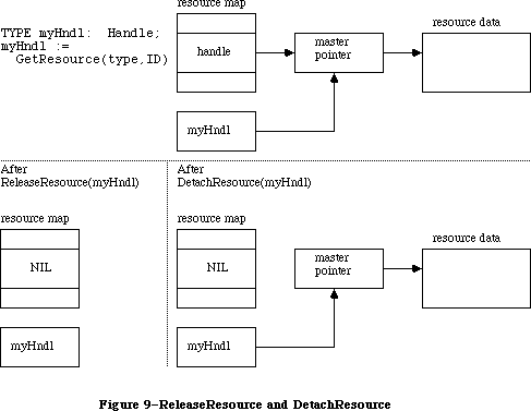 Figure 9–ReleaseResource and DetachResource
If the given handle isn’t a handle to a resource, ReleaseResource will do nothing and the ResError function will return the result code resNotFound. ReleaseResource won’t let you release a resource whose resChanged attribute has been set; however, ResError will still return noErr.
PROCEDURE DetachResource (theResource: Handle);
Given a handle to a resource, DetachResource replaces the handle to that resource in the resource map with NIL (see Figure 9 above). The given handle will no longer be recognized as a handle to a resource; if the Resource Manager is subsequently called to get the detached resource, a new handle will be allocated.
DetachResource is useful if you want the resource data to be accessed only by yourself through the given handle and not by the Resource Manager. DetachResource is also useful in the unusual case that you don’t want a resource to be released when a resource file is closed. To copy a resource, you can call DetachResource followed by AddResource (with a new resource ID).
If the given handle isn’t a handle to a resource, DetachResource will do nothing and the ResError function will return the result code resNotFound. DetachResource won’t let you detach a resource whose resChanged attribute has been set; however, ResError will still return noErr.
_______________________________________________________________________________
»Getting Resource Information
FUNCTION UniqueID (theType: ResType) : INTEGER;
UniqueID returns an ID number greater than 0 that isn’t currently assigned to any resource of the given type in any open resource file. Using this number when you add a new resource to a resource file ensures that you won’t duplicate a resource ID and override an existing resource.
Warning: It’s possible that UniqueID will return an ID in the range reserved
for system resources (0 to 127). You should check that the ID
returned is greater than 127; if it isn’t, call UniqueID again.
FUNCTION Unique1ID (theType: ResType) : INTEGER;
Unique1ID is the same as UniqueID except that the ID number it returns is unique only with respect to resources in the current resource file.
PROCEDURE GetResInfo (theResource: Handle; VAR theID: INTEGER;
VAR theType: ResType; VAR name: Str255);
Given a handle to a resource, GetResInfo returns the ID number, type, and name of the resource. If the given handle isn’t a handle to a resource, GetResInfo will do nothing and the ResError function will return the result code resNotFound.
FUNCTION GetResAttrs (theResource: Handle) : INTEGER;
Given a handle to a resource, GetResAttrs returns the resource attributes for the resource. (Resource attributes are described above under “Resource References”.) If the given handle isn’t a handle to a resource, GetResAttrs will do nothing and the ResError function will return the result code resNotFound.
FUNCTION SizeResource (the Resource: Handle) : LONGINT;
Assembly-language note: The macro you invoke to call SizeResource from
assembly language is named _SizeRsrc.
Given a handle to a resource, SizeResource returns the size in bytes of the resource in the resource file. If the given handle isn’t a handle to a resource, SizeResource will return –1 and the ResError function will return the result code resNotFound. It’s a good idea to call SizeResource and ensure that sufficient space is available before reading a resource into memory.
FUNCTION MaxSizeRsrc (theResource: Handle) : LONGINT;
MaxSizeRsrc is similar to SizeResource except that it does not cause the disk to be read; instead it determines the size (in bytes) of the resource from the offsets found in the resource map.
Since MaxSizeRsrc does not read from the disk, it returns only the maximum size of the resource. In other words, you can count on the resource not being larger than the number of bytes reported by MaxSizeRsrc; it’s possible, however, that the resource is actually smaller than the resource map indicates (because the file has not yet been compacted). If called after UpdateResFile, MaxSizeRsrc will return the correct size of the resource.
_______________________________________________________________________________
»Modifying Resources
Except for UpdateResFile and WriteResource, all the routines described below change the resource map in memory and not the resource file itself.
PROCEDURE SetResInfo (theResource: Handle; theID: INTEGER; name: Str255);
Given a handle to a resource, SetResInfo changes the ID number and name of the resource to the given ID number and name.
Assembly-language note: If you pass 0 for the name parameter, the name will
not be changed.
Warning: It’s a dangerous practice to change the ID number and name of a
system resource, because other applications may already access the
resource and may no longer work properly.
The change will be written to the resource file when the file is updated if you follow SetResInfo with a call to ChangedResource.
Warning: Even if you don’t call ChangedResource for this resource, the change
may be written to the resource file when the file is updated. If
you’ve ever called ChangedResource for any resource in the file, or
if you’ve added or removed a resource, the Resource Manager will
write out the entire resource map when it updates the file, so all
changes made to resource information in the map will become permanent.
If you want any of the changes to be temporary, you’ll have to
restore the original information before the file is updated.
_______________________________________________________________________________
SetResInfo does nothing in the following cases:
• The given handle isn’t a handle to a resource. The ResError function will
return the result code resNotFound.
• The resource map becomes too large to fit in memory (which can happen if
a name is passed) or the modified resource file can’t be written out to
the disk. ResError will return an appropriate Operating System result code.
• The resProtected attribute for the resource is set. ResError will,
however, return the result code noErr.
PROCEDURE SetResAttrs (theResource: Handle; attrs: INTEGER);
Given a handle to a resource, SetResAttrs sets the resource attributes for the resource to attrs. (Resource attributes are described above under “Resource References”.) The resProtected attribute takes effect immediately; the others take effect the next time the resource is read in.
Warning: Do not use SetResAttrs to set the resChanged attribute; you must
call ChangedResource instead. Be sure that the attrs parameter
passed to SetResAttrs doesn’t change the current setting of this
attribute; to determine the current setting, first call GetResAttrs.
The attributes set with SetResAttrs will be written to the resource file when the file is updated if you follow SetResAttrs with a call to ChangedResource. However, even if you don’t call ChangedResource for this resource, the change may be written to the resource file when the file is updated. See the last warning for SetResInfo (above).
X-Ref: Technical Note #78
If the given handle isn’t a handle to a resource, SetResAttrs will do nothing and the ResError function will return the result code resNotFound.
PROCEDURE ChangedResource (theResource: Handle);
Call ChangedResource after changing either the information about a resource in the resource map (as described above under SetResInfo and SetResAttrs) or the resource data for a resource, if you want the change to be permanent. Given a handle to a resource, ChangedResource sets the resChanged attribute for the resource. This attribute tells the Resource Manager to do both of the following:
• write the resource data for the resource to the resource file when the file
is updated or when WriteResource is called
• write the entire resource map to the resource file when the file is updated
Warning: If you change information in the resource map with SetResInfo or
SetResAttrs and then call ChangedResource, remember that not only
the resource map but also the resource data will be written out when
the resource file is updated.
To change the resource data for a purgeable resource and make the change permanent, you have to take special precautions to ensure that the resource
won’t be purged while you’re changing it. You can make the resource temporarily unpurgeable and then write it out with WriteResource before making it purgeable again. You have to use the Memory Manager procedures HNoPurge and HPurge to make the resource unpurgeable and purgeable; SetResAttrs can’t be used because it won’t take effect immediately. For example:
myHndl := GetResource(type,ID); {or LoadResource(myHndl) if }
{ you've gotten it previously}
HNoPurge(myHndl); {make it unpurgeable}
. . . {make the changes here}
ChangedResource(myHndl); {mark it changed}
WriteResource(myHndl); {write it out}
HPurge(myHndl) {make it purgeable again}
Or, instead of calling WriteResource to write the data out immediately, you can call SetResPurge(TRUE) before making any changes to purgeable resource data.
ChangedResource does nothing in the following cases:
• The given handle isn’t a handle to a resource. The ResError function will
return the result code resNotFound.
• The modified resource file can’t be written out to the disk. ResError will
return an appropriate Operating System result code.
• The resProtected attribute for the modified resource is set. ResError will,
however, return the result code noErr.
X-Ref: Technical Note #188
Warning: Be aware that if the modified file can’t be written out to the disk,
the resChanged attribute won’t be set. This means that when
WriteResource is called, it won’t know that the resource file has
been changed; it won’t write out the modified file and no error will
be returned. For this reason, always check to see that
ChangedResource returns noErr.
PROCEDURE AddResource (theData: Handle; theType: ResType;
theID: INTEGER; name: Str255);
Given a handle to data in memory (not a handle to an existing resource), AddResource adds to the current resource file a resource reference that points to the data. It sets the resChanged attribute for the resource, so the data will be written to the resource file when the file is updated or when WriteResource is called. If the given handle is empty, zero-length resource data will be written.
Note: To make a copy of an existing resource, call DetachResource before
calling AddResource. To add the same data to several different resource
files, call the Operating System Utility function HandToHand to
duplicate the handle for each resource reference.
AddResource does nothing in the following cases:
• The given handle is NIL or is already a handle to an existing resource
. The ResError function will return the result code addResFailed.
• The resource map becomes too large to fit in memory or the modified
resource file can’t be written out to the disk. ResError will return an
appropriate Operating System result code. (The warning under
ChangedResource above concerning the resChanged attribute also applies
to AddResource.)
Warning: AddResource doesn’t verify whether the resource ID you pass is
already assigned to another resource of the same type; be sure to
call UniqueID before adding a resource.
PROCEDURE RmveResource (theResource: Handle);
Given a handle to a resource in the current resource file, RmveResource removes its resource reference. The resource data will be removed from the resource file when the file is updated.
Note: RmveResource doesn’t release the memory occupied by the resource data;
to do that, call the Memory Manager procedure DisposHandle after calling
RmveResource.
If the resProtected attribute for the resource is set or if the given handle isn’t a handle to a resource in the current resource file, RmveResource will do nothing and the ResError function will return the result code rmvResFailed.
PROCEDURE UpdateResFile (refNum: INTEGER);
Given the reference number of a resource file, UpdateResFile does the following:
• Changes, adds, or removes resource data in the file as appropriate to
match the map. Remember that changed resource data is written out only if
you called ChangedResource (and the call was successful). UpdateResFile
calls WriteResource to write out changed or added resources.
• Compacts the resource file, closing up any empty space created when a
resource was removed, made smaller, or made larger. (If the size of a
changed resource is greater than its original size in the resource file,
it’s written at the end of the file rather than at its original location;
the space occupied by the original is then compacted.) The actual size of
the resource file will be adjusted when a resource is removed or made
larger, but not when a resource is made smaller.
• Writes out the resource map of the resource file, if you ever called
ChangedResource for any resource in the file or if you added or removed
a resource. All changes to resource information in the map will become
permanent as a result of this, so if you want any such changes to be
temporary, you must restore the original information before calling
UpdateResFile.
If there’s no open resource file with the given reference number, UpdateResFile will do nothing and the ResError function will return the result code resFNotFound. A refNum of 0 represents the system resource file.
The CloseResFile procedure calls UpdateResFile before it closes the resource file, so you only need to call UpdateResFile yourself if you want to update the file without closing it.
PROCEDURE WriteResource (theResource: Handle);
Given a handle to a resource, WriteResource checks the resChanged attribute for that resource and, if it’s set (which it will be if you called ChangedResource or AddResource successfully), writes its resource data to the resource file and clears its resChanged attribute.
Warning: Be aware that ChangedResource and AddResource determine whether the
modified file can be written out to the disk; if it can’t, the
resChanged attribute won’t be set and WriteResource will be unaware
of the modifications. For this reason, always verify that
ChangedResource and AddResource return noErr.
If the resource is purgeable and has been purged, zero-length resource data will be written. WriteResource does nothing if the resProtected attribute for the resource is set or if the resChanged attribute isn’t set; in both cases, however, the ResError function will return the result code noErr. If the given handle isn’t a handle to a resource, WriteResource will do nothing and the ResError function will return the result code resNotFound.
Since the resource file is updated when the application terminates or when you call UpdateResFile (or CloseResFile, which calls UpdateResFile), you only need to call WriteResource if you want to write out just one or a few resources immediately.
Warning: The maximum size for a resource to be written to a resource file is
32K bytes.
PROCEDURE SetResPurge (install: BOOLEAN);
SetResPurge(TRUE) sets a “hook” in the Memory Manager such that before purging data specified by a handle, the Memory Manager will first pass the handle to the Resource Manager. The Resource Manager will determine whether the handle is that of a resource in the application heap and, if so, will call WriteResource to write the resource data for that resource to the resource file if its resChanged attribute is set (see ChangedResource and WriteResource). SetResPurge(FALSE) restores the normal state, clearing the hook so that the Memory Manager will once again purge without checking with the Resource Manager.
SetResPurge(TRUE) is useful in applications that modify purgeable resources. You still have to make the resources temporarily unpurgeable while making the changes, as shown in the description of ChangedResource, but you can set the purge hook instead of writing the data out immediately with WriteResource. Notice that you won’t know exactly when the resources are being written out; most applications will want more control than this. If you wish, you can set your own such hook; for details, refer to the section “Memory Manager Data Structures” in the Memory Manager chapter.
_______________________________________________________________________________
»ADVANCED ROUTINES
_______________________________________________________________________________
The routines described in this section allow advanced programmers to have even greater control over resource file operations. Just as individual resources have attributes, an entire resource file also has attributes, which these routines manipulate. Like the attributes of individual resources, resource file attributes are specified by bits in the low-order byte of a word. The Resource Manager provides the following masks for setting or testing these bits:
CONST mapReadOnly = 128; {set if file is read-only}
mapCompact = 64; {set to compact file on update}
mapChanged = 32; {set to write map on update}
When the mapReadOnly attribute is set, the Resource Manager will neither write anything to the resource file nor check whether the file can be written out to the disk when the resource map is modified. When this attribute is set, UpdateResFile and WriteResource will do nothing, but the ResError function will return the result code noErr.
Warning: If you set mapReadOnly but then later clear it, the resource file
will be written even if there’s no room for it on the disk. This
would destroy the file.
The mapCompact attribute causes the resource file to be compacted when the file is updated. It’s set by the Resource Manager when a resource is removed, or when a resource is made larger and thus has to be written at the end of the resource file. You may want to set mapCompact to force compaction when you’ve only made resources smaller.
The mapChanged attribute causes the resource map to be written to the resource file when the file is updated. It’s set by the Resource Manager when you call ChangedResource or when you add or remove a resource. You can set mapChanged if, for example, you’ve changed resource attributes only and don’t want to call ChangedResource because you don’t want the resource data to be written out.
FUNCTION GetResFileAttrs (refNum: INTEGER) : INTEGER;
Given the reference number of a resource file, GetResFileAttrs returns the resource file attributes for the file. If there’s no resource file with the given reference number, GetResFileAttrs will do nothing and the ResError function will return the result code resFNotFound. A refNum of 0 represents the system resource file.
PROCEDURE SetResFileAttrs (refNum: INTEGER; attrs: INTEGER);
Given the reference number of a resource file, SetResFileAttrs sets the resource file attributes of the file to attrs. If there’s no resource file with the given reference number, SetResFileAttrs will do nothing but the ResError function will return the result code noErr. A refNum of 0 represents the system resource file, but you shouldn’t change its resource file attributes.
FUNCTION RsrcMapEntry (theResource: Handle) : LONGINT;
RsrcMapEntry provides a way to access the resource references in the resource map. Given a handle to a resource, RsrcMapEntry returns the offset of the resource’s reference from the beginning of the resource map. (For more information on resource references and the structure of a resource map, see the section “Format of a Resource File” in the Resource Manager chapter.) If it doesn’t find the resource, RsrcMapEntry returns NIL and the ResError function will return the result code resNotFound. If you pass it a NIL handle, RsrcMapEntry will return garbage but ResError will return the result code noErr.
Warning: Since routines are provided for opening, accessing, and changing
resources, there’s really no reason to access resources directly.
To avoid damaging the resource file, you should be extremely careful
if you use RsrcMapEntry.
FUNCTION OpenRFPerm (fileName: Str255; vRefNum: INTEGER;
permission: Byte) : INTEGER;
OpenRFPerm is similar to OpenResFile except that it allows you to specify the read/write permission of the resource file the first time it is opened; OpenRFPerm also lets you specify in vRefNum the directory or volume on which the file is located (see the File Manager chapter for more details on directories). Permission can have any of the values that you would pass to the File Manager; these values are given in “Low-Level File Manager Routines” in the File Manager chapter.
OpenRFPerm, like OpenResFile, will not open the specified file twice; it simply returns the reference number already assigned to the file. In other words, OpenRFPerm cannot be used to open a second access path to a resource file nor can it be used to change the permission of an already open file. Since OpenRFPerm gives no indication of whether the file was already open, there’s no way to tell whether the file’s open permission is what you specified or what was specified by an earlier call.
X-Ref: Technical Note #185
Note: The shared read/write permission described in the File Manager chapter
has no effect with OpenRFPerm since the Resource Manager is unable to
deal with a portion of a resource file.
_______________________________________________________________________________
»RESOURCES WITHIN RESOURCES
_______________________________________________________________________________
Resources may point to other resources; this section discusses how this is normally done, for programmers who are interested in background information about resources or who are defining their own resource types.
In a resource file, one resource points to another with the ID number of the other resource. For example, the resource data for a menu includes the ID number of the menu’s definition procedure (a separate resource that determines how the menu looks and behaves). To work with the resource data in memory, however, it’s faster and more convenient to have a handle to the other resource rather than its ID number. Since a handle occupies two words, the ID number in the resource file is followed by a word containing 0; these two words together serve as a placeholder for the handle. Once the other resource has been read into memory, these two words can be replaced by a handle to it. (See Figure 10.)
Note: The practice of using the ID number followed by 0 as a placeholder is
simply a convention. If you like, you can set up your own resources to
have the ID number followed by a dummy word, or even a word of useful
information, or you can put the ID in the second rather than the first
word of the placeholder.
In the case of menus, the Menu Manager function GetMenu calls the Resource Manager to read the menu and the menu definition procedure into memory, and then replaces the placeholder in the menu with the handle to the procedure. There may be other cases where you call the Resource Manager directly and store the handle in the placeholder yourself. It might be useful in these cases to call HomeResFile to learn which resource file the original resource is located in, and then, before getting the resource it points to, call UseResFile to set the current resource file to that file. This will ensure that the resource pointed to is read from that same file (rather than one that was opened after it).
Warning: If you modify a resource that points to another resource and you
make the change permanent by calling ChangedResource, be sure you
reverse the process described here, restoring the other resource’s
ID number in the placeholder.
Figure 9–ReleaseResource and DetachResource
If the given handle isn’t a handle to a resource, ReleaseResource will do nothing and the ResError function will return the result code resNotFound. ReleaseResource won’t let you release a resource whose resChanged attribute has been set; however, ResError will still return noErr.
PROCEDURE DetachResource (theResource: Handle);
Given a handle to a resource, DetachResource replaces the handle to that resource in the resource map with NIL (see Figure 9 above). The given handle will no longer be recognized as a handle to a resource; if the Resource Manager is subsequently called to get the detached resource, a new handle will be allocated.
DetachResource is useful if you want the resource data to be accessed only by yourself through the given handle and not by the Resource Manager. DetachResource is also useful in the unusual case that you don’t want a resource to be released when a resource file is closed. To copy a resource, you can call DetachResource followed by AddResource (with a new resource ID).
If the given handle isn’t a handle to a resource, DetachResource will do nothing and the ResError function will return the result code resNotFound. DetachResource won’t let you detach a resource whose resChanged attribute has been set; however, ResError will still return noErr.
_______________________________________________________________________________
»Getting Resource Information
FUNCTION UniqueID (theType: ResType) : INTEGER;
UniqueID returns an ID number greater than 0 that isn’t currently assigned to any resource of the given type in any open resource file. Using this number when you add a new resource to a resource file ensures that you won’t duplicate a resource ID and override an existing resource.
Warning: It’s possible that UniqueID will return an ID in the range reserved
for system resources (0 to 127). You should check that the ID
returned is greater than 127; if it isn’t, call UniqueID again.
FUNCTION Unique1ID (theType: ResType) : INTEGER;
Unique1ID is the same as UniqueID except that the ID number it returns is unique only with respect to resources in the current resource file.
PROCEDURE GetResInfo (theResource: Handle; VAR theID: INTEGER;
VAR theType: ResType; VAR name: Str255);
Given a handle to a resource, GetResInfo returns the ID number, type, and name of the resource. If the given handle isn’t a handle to a resource, GetResInfo will do nothing and the ResError function will return the result code resNotFound.
FUNCTION GetResAttrs (theResource: Handle) : INTEGER;
Given a handle to a resource, GetResAttrs returns the resource attributes for the resource. (Resource attributes are described above under “Resource References”.) If the given handle isn’t a handle to a resource, GetResAttrs will do nothing and the ResError function will return the result code resNotFound.
FUNCTION SizeResource (the Resource: Handle) : LONGINT;
Assembly-language note: The macro you invoke to call SizeResource from
assembly language is named _SizeRsrc.
Given a handle to a resource, SizeResource returns the size in bytes of the resource in the resource file. If the given handle isn’t a handle to a resource, SizeResource will return –1 and the ResError function will return the result code resNotFound. It’s a good idea to call SizeResource and ensure that sufficient space is available before reading a resource into memory.
FUNCTION MaxSizeRsrc (theResource: Handle) : LONGINT;
MaxSizeRsrc is similar to SizeResource except that it does not cause the disk to be read; instead it determines the size (in bytes) of the resource from the offsets found in the resource map.
Since MaxSizeRsrc does not read from the disk, it returns only the maximum size of the resource. In other words, you can count on the resource not being larger than the number of bytes reported by MaxSizeRsrc; it’s possible, however, that the resource is actually smaller than the resource map indicates (because the file has not yet been compacted). If called after UpdateResFile, MaxSizeRsrc will return the correct size of the resource.
_______________________________________________________________________________
»Modifying Resources
Except for UpdateResFile and WriteResource, all the routines described below change the resource map in memory and not the resource file itself.
PROCEDURE SetResInfo (theResource: Handle; theID: INTEGER; name: Str255);
Given a handle to a resource, SetResInfo changes the ID number and name of the resource to the given ID number and name.
Assembly-language note: If you pass 0 for the name parameter, the name will
not be changed.
Warning: It’s a dangerous practice to change the ID number and name of a
system resource, because other applications may already access the
resource and may no longer work properly.
The change will be written to the resource file when the file is updated if you follow SetResInfo with a call to ChangedResource.
Warning: Even if you don’t call ChangedResource for this resource, the change
may be written to the resource file when the file is updated. If
you’ve ever called ChangedResource for any resource in the file, or
if you’ve added or removed a resource, the Resource Manager will
write out the entire resource map when it updates the file, so all
changes made to resource information in the map will become permanent.
If you want any of the changes to be temporary, you’ll have to
restore the original information before the file is updated.
_______________________________________________________________________________
SetResInfo does nothing in the following cases:
• The given handle isn’t a handle to a resource. The ResError function will
return the result code resNotFound.
• The resource map becomes too large to fit in memory (which can happen if
a name is passed) or the modified resource file can’t be written out to
the disk. ResError will return an appropriate Operating System result code.
• The resProtected attribute for the resource is set. ResError will,
however, return the result code noErr.
PROCEDURE SetResAttrs (theResource: Handle; attrs: INTEGER);
Given a handle to a resource, SetResAttrs sets the resource attributes for the resource to attrs. (Resource attributes are described above under “Resource References”.) The resProtected attribute takes effect immediately; the others take effect the next time the resource is read in.
Warning: Do not use SetResAttrs to set the resChanged attribute; you must
call ChangedResource instead. Be sure that the attrs parameter
passed to SetResAttrs doesn’t change the current setting of this
attribute; to determine the current setting, first call GetResAttrs.
The attributes set with SetResAttrs will be written to the resource file when the file is updated if you follow SetResAttrs with a call to ChangedResource. However, even if you don’t call ChangedResource for this resource, the change may be written to the resource file when the file is updated. See the last warning for SetResInfo (above).
X-Ref: Technical Note #78
If the given handle isn’t a handle to a resource, SetResAttrs will do nothing and the ResError function will return the result code resNotFound.
PROCEDURE ChangedResource (theResource: Handle);
Call ChangedResource after changing either the information about a resource in the resource map (as described above under SetResInfo and SetResAttrs) or the resource data for a resource, if you want the change to be permanent. Given a handle to a resource, ChangedResource sets the resChanged attribute for the resource. This attribute tells the Resource Manager to do both of the following:
• write the resource data for the resource to the resource file when the file
is updated or when WriteResource is called
• write the entire resource map to the resource file when the file is updated
Warning: If you change information in the resource map with SetResInfo or
SetResAttrs and then call ChangedResource, remember that not only
the resource map but also the resource data will be written out when
the resource file is updated.
To change the resource data for a purgeable resource and make the change permanent, you have to take special precautions to ensure that the resource
won’t be purged while you’re changing it. You can make the resource temporarily unpurgeable and then write it out with WriteResource before making it purgeable again. You have to use the Memory Manager procedures HNoPurge and HPurge to make the resource unpurgeable and purgeable; SetResAttrs can’t be used because it won’t take effect immediately. For example:
myHndl := GetResource(type,ID); {or LoadResource(myHndl) if }
{ you've gotten it previously}
HNoPurge(myHndl); {make it unpurgeable}
. . . {make the changes here}
ChangedResource(myHndl); {mark it changed}
WriteResource(myHndl); {write it out}
HPurge(myHndl) {make it purgeable again}
Or, instead of calling WriteResource to write the data out immediately, you can call SetResPurge(TRUE) before making any changes to purgeable resource data.
ChangedResource does nothing in the following cases:
• The given handle isn’t a handle to a resource. The ResError function will
return the result code resNotFound.
• The modified resource file can’t be written out to the disk. ResError will
return an appropriate Operating System result code.
• The resProtected attribute for the modified resource is set. ResError will,
however, return the result code noErr.
X-Ref: Technical Note #188
Warning: Be aware that if the modified file can’t be written out to the disk,
the resChanged attribute won’t be set. This means that when
WriteResource is called, it won’t know that the resource file has
been changed; it won’t write out the modified file and no error will
be returned. For this reason, always check to see that
ChangedResource returns noErr.
PROCEDURE AddResource (theData: Handle; theType: ResType;
theID: INTEGER; name: Str255);
Given a handle to data in memory (not a handle to an existing resource), AddResource adds to the current resource file a resource reference that points to the data. It sets the resChanged attribute for the resource, so the data will be written to the resource file when the file is updated or when WriteResource is called. If the given handle is empty, zero-length resource data will be written.
Note: To make a copy of an existing resource, call DetachResource before
calling AddResource. To add the same data to several different resource
files, call the Operating System Utility function HandToHand to
duplicate the handle for each resource reference.
AddResource does nothing in the following cases:
• The given handle is NIL or is already a handle to an existing resource
. The ResError function will return the result code addResFailed.
• The resource map becomes too large to fit in memory or the modified
resource file can’t be written out to the disk. ResError will return an
appropriate Operating System result code. (The warning under
ChangedResource above concerning the resChanged attribute also applies
to AddResource.)
Warning: AddResource doesn’t verify whether the resource ID you pass is
already assigned to another resource of the same type; be sure to
call UniqueID before adding a resource.
PROCEDURE RmveResource (theResource: Handle);
Given a handle to a resource in the current resource file, RmveResource removes its resource reference. The resource data will be removed from the resource file when the file is updated.
Note: RmveResource doesn’t release the memory occupied by the resource data;
to do that, call the Memory Manager procedure DisposHandle after calling
RmveResource.
If the resProtected attribute for the resource is set or if the given handle isn’t a handle to a resource in the current resource file, RmveResource will do nothing and the ResError function will return the result code rmvResFailed.
PROCEDURE UpdateResFile (refNum: INTEGER);
Given the reference number of a resource file, UpdateResFile does the following:
• Changes, adds, or removes resource data in the file as appropriate to
match the map. Remember that changed resource data is written out only if
you called ChangedResource (and the call was successful). UpdateResFile
calls WriteResource to write out changed or added resources.
• Compacts the resource file, closing up any empty space created when a
resource was removed, made smaller, or made larger. (If the size of a
changed resource is greater than its original size in the resource file,
it’s written at the end of the file rather than at its original location;
the space occupied by the original is then compacted.) The actual size of
the resource file will be adjusted when a resource is removed or made
larger, but not when a resource is made smaller.
• Writes out the resource map of the resource file, if you ever called
ChangedResource for any resource in the file or if you added or removed
a resource. All changes to resource information in the map will become
permanent as a result of this, so if you want any such changes to be
temporary, you must restore the original information before calling
UpdateResFile.
If there’s no open resource file with the given reference number, UpdateResFile will do nothing and the ResError function will return the result code resFNotFound. A refNum of 0 represents the system resource file.
The CloseResFile procedure calls UpdateResFile before it closes the resource file, so you only need to call UpdateResFile yourself if you want to update the file without closing it.
PROCEDURE WriteResource (theResource: Handle);
Given a handle to a resource, WriteResource checks the resChanged attribute for that resource and, if it’s set (which it will be if you called ChangedResource or AddResource successfully), writes its resource data to the resource file and clears its resChanged attribute.
Warning: Be aware that ChangedResource and AddResource determine whether the
modified file can be written out to the disk; if it can’t, the
resChanged attribute won’t be set and WriteResource will be unaware
of the modifications. For this reason, always verify that
ChangedResource and AddResource return noErr.
If the resource is purgeable and has been purged, zero-length resource data will be written. WriteResource does nothing if the resProtected attribute for the resource is set or if the resChanged attribute isn’t set; in both cases, however, the ResError function will return the result code noErr. If the given handle isn’t a handle to a resource, WriteResource will do nothing and the ResError function will return the result code resNotFound.
Since the resource file is updated when the application terminates or when you call UpdateResFile (or CloseResFile, which calls UpdateResFile), you only need to call WriteResource if you want to write out just one or a few resources immediately.
Warning: The maximum size for a resource to be written to a resource file is
32K bytes.
PROCEDURE SetResPurge (install: BOOLEAN);
SetResPurge(TRUE) sets a “hook” in the Memory Manager such that before purging data specified by a handle, the Memory Manager will first pass the handle to the Resource Manager. The Resource Manager will determine whether the handle is that of a resource in the application heap and, if so, will call WriteResource to write the resource data for that resource to the resource file if its resChanged attribute is set (see ChangedResource and WriteResource). SetResPurge(FALSE) restores the normal state, clearing the hook so that the Memory Manager will once again purge without checking with the Resource Manager.
SetResPurge(TRUE) is useful in applications that modify purgeable resources. You still have to make the resources temporarily unpurgeable while making the changes, as shown in the description of ChangedResource, but you can set the purge hook instead of writing the data out immediately with WriteResource. Notice that you won’t know exactly when the resources are being written out; most applications will want more control than this. If you wish, you can set your own such hook; for details, refer to the section “Memory Manager Data Structures” in the Memory Manager chapter.
_______________________________________________________________________________
»ADVANCED ROUTINES
_______________________________________________________________________________
The routines described in this section allow advanced programmers to have even greater control over resource file operations. Just as individual resources have attributes, an entire resource file also has attributes, which these routines manipulate. Like the attributes of individual resources, resource file attributes are specified by bits in the low-order byte of a word. The Resource Manager provides the following masks for setting or testing these bits:
CONST mapReadOnly = 128; {set if file is read-only}
mapCompact = 64; {set to compact file on update}
mapChanged = 32; {set to write map on update}
When the mapReadOnly attribute is set, the Resource Manager will neither write anything to the resource file nor check whether the file can be written out to the disk when the resource map is modified. When this attribute is set, UpdateResFile and WriteResource will do nothing, but the ResError function will return the result code noErr.
Warning: If you set mapReadOnly but then later clear it, the resource file
will be written even if there’s no room for it on the disk. This
would destroy the file.
The mapCompact attribute causes the resource file to be compacted when the file is updated. It’s set by the Resource Manager when a resource is removed, or when a resource is made larger and thus has to be written at the end of the resource file. You may want to set mapCompact to force compaction when you’ve only made resources smaller.
The mapChanged attribute causes the resource map to be written to the resource file when the file is updated. It’s set by the Resource Manager when you call ChangedResource or when you add or remove a resource. You can set mapChanged if, for example, you’ve changed resource attributes only and don’t want to call ChangedResource because you don’t want the resource data to be written out.
FUNCTION GetResFileAttrs (refNum: INTEGER) : INTEGER;
Given the reference number of a resource file, GetResFileAttrs returns the resource file attributes for the file. If there’s no resource file with the given reference number, GetResFileAttrs will do nothing and the ResError function will return the result code resFNotFound. A refNum of 0 represents the system resource file.
PROCEDURE SetResFileAttrs (refNum: INTEGER; attrs: INTEGER);
Given the reference number of a resource file, SetResFileAttrs sets the resource file attributes of the file to attrs. If there’s no resource file with the given reference number, SetResFileAttrs will do nothing but the ResError function will return the result code noErr. A refNum of 0 represents the system resource file, but you shouldn’t change its resource file attributes.
FUNCTION RsrcMapEntry (theResource: Handle) : LONGINT;
RsrcMapEntry provides a way to access the resource references in the resource map. Given a handle to a resource, RsrcMapEntry returns the offset of the resource’s reference from the beginning of the resource map. (For more information on resource references and the structure of a resource map, see the section “Format of a Resource File” in the Resource Manager chapter.) If it doesn’t find the resource, RsrcMapEntry returns NIL and the ResError function will return the result code resNotFound. If you pass it a NIL handle, RsrcMapEntry will return garbage but ResError will return the result code noErr.
Warning: Since routines are provided for opening, accessing, and changing
resources, there’s really no reason to access resources directly.
To avoid damaging the resource file, you should be extremely careful
if you use RsrcMapEntry.
FUNCTION OpenRFPerm (fileName: Str255; vRefNum: INTEGER;
permission: Byte) : INTEGER;
OpenRFPerm is similar to OpenResFile except that it allows you to specify the read/write permission of the resource file the first time it is opened; OpenRFPerm also lets you specify in vRefNum the directory or volume on which the file is located (see the File Manager chapter for more details on directories). Permission can have any of the values that you would pass to the File Manager; these values are given in “Low-Level File Manager Routines” in the File Manager chapter.
OpenRFPerm, like OpenResFile, will not open the specified file twice; it simply returns the reference number already assigned to the file. In other words, OpenRFPerm cannot be used to open a second access path to a resource file nor can it be used to change the permission of an already open file. Since OpenRFPerm gives no indication of whether the file was already open, there’s no way to tell whether the file’s open permission is what you specified or what was specified by an earlier call.
X-Ref: Technical Note #185
Note: The shared read/write permission described in the File Manager chapter
has no effect with OpenRFPerm since the Resource Manager is unable to
deal with a portion of a resource file.
_______________________________________________________________________________
»RESOURCES WITHIN RESOURCES
_______________________________________________________________________________
Resources may point to other resources; this section discusses how this is normally done, for programmers who are interested in background information about resources or who are defining their own resource types.
In a resource file, one resource points to another with the ID number of the other resource. For example, the resource data for a menu includes the ID number of the menu’s definition procedure (a separate resource that determines how the menu looks and behaves). To work with the resource data in memory, however, it’s faster and more convenient to have a handle to the other resource rather than its ID number. Since a handle occupies two words, the ID number in the resource file is followed by a word containing 0; these two words together serve as a placeholder for the handle. Once the other resource has been read into memory, these two words can be replaced by a handle to it. (See Figure 10.)
Note: The practice of using the ID number followed by 0 as a placeholder is
simply a convention. If you like, you can set up your own resources to
have the ID number followed by a dummy word, or even a word of useful
information, or you can put the ID in the second rather than the first
word of the placeholder.
In the case of menus, the Menu Manager function GetMenu calls the Resource Manager to read the menu and the menu definition procedure into memory, and then replaces the placeholder in the menu with the handle to the procedure. There may be other cases where you call the Resource Manager directly and store the handle in the placeholder yourself. It might be useful in these cases to call HomeResFile to learn which resource file the original resource is located in, and then, before getting the resource it points to, call UseResFile to set the current resource file to that file. This will ensure that the resource pointed to is read from that same file (rather than one that was opened after it).
Warning: If you modify a resource that points to another resource and you
make the change permanent by calling ChangedResource, be sure you
reverse the process described here, restoring the other resource’s
ID number in the placeholder.
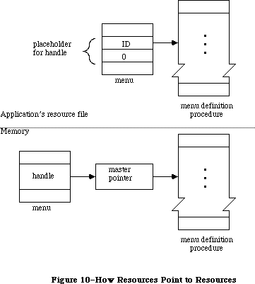 Figure 10–How Resources Point to Resources
_______________________________________________________________________________
»FORMAT OF A RESOURCE FILE
_______________________________________________________________________________
X-Ref: Technical Note #141
X-Ref: Technical Note #203
You need to know the exact format of a resource file, described below, only if you’re writing a program that will create or modify resource files directly; you don’t have to know it to be able to use the Resource Manager routines.
Figure 10–How Resources Point to Resources
_______________________________________________________________________________
»FORMAT OF A RESOURCE FILE
_______________________________________________________________________________
X-Ref: Technical Note #141
X-Ref: Technical Note #203
You need to know the exact format of a resource file, described below, only if you’re writing a program that will create or modify resource files directly; you don’t have to know it to be able to use the Resource Manager routines.
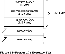 Figure 11–Format of a Resource File
As illustrated in Figure 11, every resource file begins with a resource header. The resource header gives the offsets to and lengths of the resource data and resource map parts of the file, as follows:
Number of bytes Contents
4 bytes Offset from beginning of resource file to resource data
4 bytes Offset from beginning of resource file to resource map
4 bytes Length of resource data
4 bytes Length of resource map
Note: All offsets and lengths in the resource file are given in bytes.
This is what immediately follows the resource header:
Number of bytes Contents
112 bytes Reserved for system use
128 bytes Reserved for application data
X-Ref: Technical Note #62
The application data may be whatever you want.
The resource data follows the space reserved for the application data. It consists of the following for each resource in the file:
Number of bytes Contents
For each resource:
4 bytes Length of following resource data
n bytes Resource data for this resource
To learn exactly what the resource data is for a standard type of resource, see the chapter describing the part of the Toolbox that deals with that resource type.
After the resource data, the resource map begins as follows:
Number of bytes Contents
16 bytes 0 (reserved for copy of resource header)
4 bytes 0 (reserved for handle to next resource map to be searched)
2 bytes 0 (reserved for file reference number)
2 bytes Resource file attributes
2 bytes Offset from beginning of resource map to
type list (see below)
2 bytes Offset from beginning of resource map to
resource name list (see below)
After reading the resource map into memory, the Resource Manager stores the indicated information in the reserved areas at the beginning of the map.
The resource map continues with a type list, reference lists, and a resource name list. The type list contains the following:
Number of bytes Contents
2 bytes Number of resource types in the map minus 1
For each type:
4 bytes Resource type
2 bytes Number of resources of this type in the map minus 1
2 bytes Offset from beginning of type list to reference list
for resources of this type
This is followed by the reference list for each type of resource, which contains the resource references for all resources of that type. The reference lists are contiguous and in the same order as the types in the type list. The format of a reference list is as follows:
Number of bytes Contents
For each reference
of this type:
2 bytes Resource ID
2 bytes Offset from beginning of resource name list
to length of resource name, or –1 if none
1 byte Resource attributes
3 bytes Offset from beginning of resouce data to
length of data for this resource
4 bytes 0 (reserved for handle to resource)
The resource name list follows the reference list and has this format:
Number of bytes Contents
For each name:
1 byte Length of following resource name
n bytes Characters of resource name
Figure 12 shows where the various offsets lead to in a resource file, in general and also specifically for a resource reference.
Figure 11–Format of a Resource File
As illustrated in Figure 11, every resource file begins with a resource header. The resource header gives the offsets to and lengths of the resource data and resource map parts of the file, as follows:
Number of bytes Contents
4 bytes Offset from beginning of resource file to resource data
4 bytes Offset from beginning of resource file to resource map
4 bytes Length of resource data
4 bytes Length of resource map
Note: All offsets and lengths in the resource file are given in bytes.
This is what immediately follows the resource header:
Number of bytes Contents
112 bytes Reserved for system use
128 bytes Reserved for application data
X-Ref: Technical Note #62
The application data may be whatever you want.
The resource data follows the space reserved for the application data. It consists of the following for each resource in the file:
Number of bytes Contents
For each resource:
4 bytes Length of following resource data
n bytes Resource data for this resource
To learn exactly what the resource data is for a standard type of resource, see the chapter describing the part of the Toolbox that deals with that resource type.
After the resource data, the resource map begins as follows:
Number of bytes Contents
16 bytes 0 (reserved for copy of resource header)
4 bytes 0 (reserved for handle to next resource map to be searched)
2 bytes 0 (reserved for file reference number)
2 bytes Resource file attributes
2 bytes Offset from beginning of resource map to
type list (see below)
2 bytes Offset from beginning of resource map to
resource name list (see below)
After reading the resource map into memory, the Resource Manager stores the indicated information in the reserved areas at the beginning of the map.
The resource map continues with a type list, reference lists, and a resource name list. The type list contains the following:
Number of bytes Contents
2 bytes Number of resource types in the map minus 1
For each type:
4 bytes Resource type
2 bytes Number of resources of this type in the map minus 1
2 bytes Offset from beginning of type list to reference list
for resources of this type
This is followed by the reference list for each type of resource, which contains the resource references for all resources of that type. The reference lists are contiguous and in the same order as the types in the type list. The format of a reference list is as follows:
Number of bytes Contents
For each reference
of this type:
2 bytes Resource ID
2 bytes Offset from beginning of resource name list
to length of resource name, or –1 if none
1 byte Resource attributes
3 bytes Offset from beginning of resouce data to
length of data for this resource
4 bytes 0 (reserved for handle to resource)
The resource name list follows the reference list and has this format:
Number of bytes Contents
For each name:
1 byte Length of following resource name
n bytes Characters of resource name
Figure 12 shows where the various offsets lead to in a resource file, in general and also specifically for a resource reference.
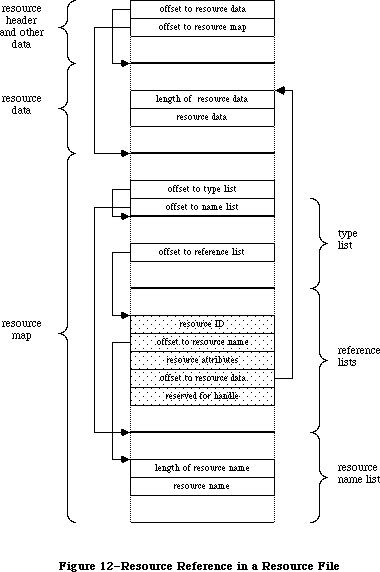 Figure 12–Resource Reference in a Resource File
_______________________________________________________________________________
»SUMMARY OF THE RESOURCE MANAGER
_______________________________________________________________________________
Constants
CONST
{ Masks for resource attributes }
resSysHeap = 64; {set if read into system heap}
resPurgeable = 32; {set if purgeable}
resLocked = 16; {set if locked}
resProtected = 8; {set if protected}
resPreload = 4; {set if to be preloaded}
resChanged = 2; {set if to be written to resource file}
{ Resource Manager result codes }
resNotFound = -192; {resource not found}
resFNotFound = -193; {resource file not found}
addResFailed = -194; {AddResource failed}
rmvResFailed = -196; {RmveResource failed}
resAttrErr = –198; {attribute inconsistent with operation}
mapReadErr = –199; {map inconsistent with operation}
{ Masks for resource file attributes }
mapReadOnly = 128; {set if file is read-only}
mapCompact = 64; {set to compact file on update}
mapChanged = 32; {set to write map on update}
_______________________________________________________________________________
Data Types
TYPE ResType = PACKED ARRAY[1..4] OF CHAR;
_______________________________________________________________________________
Routines
Initialization
FUNCTION InitResources : INTEGER;
PROCEDURE RsrcZoneInit;
Opening and Closing Resource Files
PROCEDURE CreateResFile (fileName: Str255);
FUNCTION OpenResFile (fileName: Str255) : INTEGER;
PROCEDURE CloseResFile (refNum: INTEGER);
Checking for Errors
FUNCTION ResError : INTEGER;
Setting the Current Resource File
FUNCTION CurResFile : INTEGER;
FUNCTION HomeResFile (theResource: Handle) : INTEGER;
PROCEDURE UseResFile (refNum: INTEGER);
Getting Resource Types
FUNCTION CountTypes : INTEGER;
FUNCTION Count1Types : INTEGER;
PROCEDURE GetIndType (VAR theType: ResType; index: INTEGER);
PROCEDURE Get1IndType (VAR theType: ResType; index: INTEGER);
Getting and Disposing of Resources
PROCEDURE SetResLoad (load: BOOLEAN);
FUNCTION CountResources (theType: ResType) : INTEGER;
FUNCTION Count1Resources (theType: ResType) : INTEGER;
FUNCTION GetIndResource (theType: ResType; index: INTEGER) : Handle;
FUNCTION Get1IndResource (theType: ResType; index: INTEGER) : Handle;
FUNCTION GetResource (theType: ResType; theID: INTEGER) : Handle;
FUNCTION Get1Resource (theType: ResType; theID: INTEGER) : Handle;
FUNCTION RGetResource (theType: ResType; theID: INTEGER) : Handle;
FUNCTION GetNamedResource (theType: ResType; name: Str255) : Handle;
FUNCTION Get1NamedResource (theType: ResType; name: Str255) : Handle;
PROCEDURE LoadResource (theResource: Handle);
PROCEDURE ReleaseResource (theResource: Handle);
PROCEDURE DetachResource (theResource: Handle);
Getting Resource Information
FUNCTION UniqueID (theType: ResType) : INTEGER;
FUNCTION Unique1ID (theType: ResType) : INTEGER;
PROCEDURE GetResInfo (theResource: Handle; VAR theID: INTEGER;
VAR theType: ResType; VAR name: Str255);
FUNCTION GetResAttrs (theResource: Handle) : INTEGER;
FUNCTION SizeResource (theResource: Handle) : LONGINT;
Modifying Resources
FUNCTION MaxSizeRsrc (theResource: Handle) : LONGINT;
PROCEDURE SetResInfo (theResource: Handle; theID: INTEGER;
name: Str255);
PROCEDURE SetResAttrs (theResource: Handle; attrs: INTEGER);
PROCEDURE ChangedResource (theResource: Handle);
PROCEDURE AddResource (theData: Handle; theType: ResType;
theID: INTEGER; name: Str255);
PROCEDURE RmveResource (theResource: Handle);
PROCEDURE UpdateResFile (refNum: INTEGER);
PROCEDURE WriteResource (theResource: Handle);
PROCEDURE SetResPurge (install: BOOLEAN);
Advanced Routines
FUNCTION GetResFileAttrs (refNum: INTEGER) : INTEGER;
PROCEDURE SetResFileAttrs (refNum: INTEGER; attrs: INTEGER);
FUNCTION RsrcMapEntry (theResource: Handle) : LONGINT;
FUNCTION OpenRFPerm (fileName: Str255; vRefNum: INTEGER;
permission: Byte) : INTEGER;
_______________________________________________________________________________
Assembly-Language Information
Constants
; Resource attributes
resSysHeap .EQU 6 ;set if read into system heap
resPurgeable .EQU 5 ;set if purgeable
resLocked .EQU 4 ;set if locked
resProtected .EQU 3 ;set if protected
resPreload .EQU 2 ;set if to be preloaded
resChanged .EQU 1 ;set if to be written to resource file
; Resource Manager result codes
resNotFound .EQU -192 ;resource not found
resFNotFound .EQU -193 ;resource file not found
addResFailed .EQU -194 ;AddResource failed
rmvResFailed .EQU -196 ;RmveResource failed
resAttrErr .EQU –198 ;attribute inconsistent with operation
mapReadErr .EQU –199 ;map inconsistent with operation
; Resource file attributes
mapReadOnly .EQU 7 ;set if file is read-only
mapCompact .EQU 6 ;set to compact file on update
mapChanged .EQU 5 ;set to write map on update
; Values for setting RomMapInsert and TmpResLoad
mapTrue .EQU $FFFF ;insert ROM map with TmpResLoad set to TRUE
mapFalse .EQU $FF00 ;insert ROM map with TmpResLoad set to FALSE
Special Macro Names
Pascal name Macro name
SizeResource _SizeRsrc
Get1IndType _Get1IxType
Get1IndResource _Get1IxResource
Variables
TopMapHndl Handle to resource map of most recently opened resource file
SysMapHndl Handle to map of system resource file
SysMap Reference number of system resource file (word)
CurMap Reference number of current resource file (word)
ResLoad Current SetResLoad state (word)
ResErr Current value of ResError (word)
ResErrProc Address of resource error procedure
SysResName Name of system resource file (length byte followed by
up to 19 characters)
RomMapInsert Flag for whether to insert map to the ROM resources (byte)
TmpResLoad Temporary SetResLoad state for calls using RomMapInsert (byte)
Further Reference:
_______________________________________________________________________________
File Manager
Technical Note #1, Desk Accessories and System Resources
Technical Note #6, Shortcut for Owned Resources
Technical Note #23, Life With Font/DA Mover—Desk Accessories
Technical Note #30, Font Height Tables
Technical Note #32, Reserved Resource Types
Technical Note #46, Separate Resource Files
Technical Note #50, Calling SetResLoad
Technical Note #62, Don’t Use Resource Header Application Bytes
Technical Note #74, Don’t Use the Resource Fork for Data
Technical Note #75, The Installer and Scripts
Technical Note #78, Resource Manager Tips
Technical Note #101, CreateResFile and the Poor Man’s Search Path
Technical Note #111, MoveHHi and SetResPurge
Technical Note #116, AppleShare-able Apps & the Resource Manager
Technical Note #141, Maximum Number of Resources in a File
Technical Note #185, OpenRFPerm: What your mother never told you.
Technical Note #188, ChangedResource: Too much of a good thing.
Technical Note #203, Don’t Abuse the Managers
Technical Note #214, New Resource Manager Calls
Technical Note #232, Strip With _OpenResFile and _OpenRFPerm
Figure 12–Resource Reference in a Resource File
_______________________________________________________________________________
»SUMMARY OF THE RESOURCE MANAGER
_______________________________________________________________________________
Constants
CONST
{ Masks for resource attributes }
resSysHeap = 64; {set if read into system heap}
resPurgeable = 32; {set if purgeable}
resLocked = 16; {set if locked}
resProtected = 8; {set if protected}
resPreload = 4; {set if to be preloaded}
resChanged = 2; {set if to be written to resource file}
{ Resource Manager result codes }
resNotFound = -192; {resource not found}
resFNotFound = -193; {resource file not found}
addResFailed = -194; {AddResource failed}
rmvResFailed = -196; {RmveResource failed}
resAttrErr = –198; {attribute inconsistent with operation}
mapReadErr = –199; {map inconsistent with operation}
{ Masks for resource file attributes }
mapReadOnly = 128; {set if file is read-only}
mapCompact = 64; {set to compact file on update}
mapChanged = 32; {set to write map on update}
_______________________________________________________________________________
Data Types
TYPE ResType = PACKED ARRAY[1..4] OF CHAR;
_______________________________________________________________________________
Routines
Initialization
FUNCTION InitResources : INTEGER;
PROCEDURE RsrcZoneInit;
Opening and Closing Resource Files
PROCEDURE CreateResFile (fileName: Str255);
FUNCTION OpenResFile (fileName: Str255) : INTEGER;
PROCEDURE CloseResFile (refNum: INTEGER);
Checking for Errors
FUNCTION ResError : INTEGER;
Setting the Current Resource File
FUNCTION CurResFile : INTEGER;
FUNCTION HomeResFile (theResource: Handle) : INTEGER;
PROCEDURE UseResFile (refNum: INTEGER);
Getting Resource Types
FUNCTION CountTypes : INTEGER;
FUNCTION Count1Types : INTEGER;
PROCEDURE GetIndType (VAR theType: ResType; index: INTEGER);
PROCEDURE Get1IndType (VAR theType: ResType; index: INTEGER);
Getting and Disposing of Resources
PROCEDURE SetResLoad (load: BOOLEAN);
FUNCTION CountResources (theType: ResType) : INTEGER;
FUNCTION Count1Resources (theType: ResType) : INTEGER;
FUNCTION GetIndResource (theType: ResType; index: INTEGER) : Handle;
FUNCTION Get1IndResource (theType: ResType; index: INTEGER) : Handle;
FUNCTION GetResource (theType: ResType; theID: INTEGER) : Handle;
FUNCTION Get1Resource (theType: ResType; theID: INTEGER) : Handle;
FUNCTION RGetResource (theType: ResType; theID: INTEGER) : Handle;
FUNCTION GetNamedResource (theType: ResType; name: Str255) : Handle;
FUNCTION Get1NamedResource (theType: ResType; name: Str255) : Handle;
PROCEDURE LoadResource (theResource: Handle);
PROCEDURE ReleaseResource (theResource: Handle);
PROCEDURE DetachResource (theResource: Handle);
Getting Resource Information
FUNCTION UniqueID (theType: ResType) : INTEGER;
FUNCTION Unique1ID (theType: ResType) : INTEGER;
PROCEDURE GetResInfo (theResource: Handle; VAR theID: INTEGER;
VAR theType: ResType; VAR name: Str255);
FUNCTION GetResAttrs (theResource: Handle) : INTEGER;
FUNCTION SizeResource (theResource: Handle) : LONGINT;
Modifying Resources
FUNCTION MaxSizeRsrc (theResource: Handle) : LONGINT;
PROCEDURE SetResInfo (theResource: Handle; theID: INTEGER;
name: Str255);
PROCEDURE SetResAttrs (theResource: Handle; attrs: INTEGER);
PROCEDURE ChangedResource (theResource: Handle);
PROCEDURE AddResource (theData: Handle; theType: ResType;
theID: INTEGER; name: Str255);
PROCEDURE RmveResource (theResource: Handle);
PROCEDURE UpdateResFile (refNum: INTEGER);
PROCEDURE WriteResource (theResource: Handle);
PROCEDURE SetResPurge (install: BOOLEAN);
Advanced Routines
FUNCTION GetResFileAttrs (refNum: INTEGER) : INTEGER;
PROCEDURE SetResFileAttrs (refNum: INTEGER; attrs: INTEGER);
FUNCTION RsrcMapEntry (theResource: Handle) : LONGINT;
FUNCTION OpenRFPerm (fileName: Str255; vRefNum: INTEGER;
permission: Byte) : INTEGER;
_______________________________________________________________________________
Assembly-Language Information
Constants
; Resource attributes
resSysHeap .EQU 6 ;set if read into system heap
resPurgeable .EQU 5 ;set if purgeable
resLocked .EQU 4 ;set if locked
resProtected .EQU 3 ;set if protected
resPreload .EQU 2 ;set if to be preloaded
resChanged .EQU 1 ;set if to be written to resource file
; Resource Manager result codes
resNotFound .EQU -192 ;resource not found
resFNotFound .EQU -193 ;resource file not found
addResFailed .EQU -194 ;AddResource failed
rmvResFailed .EQU -196 ;RmveResource failed
resAttrErr .EQU –198 ;attribute inconsistent with operation
mapReadErr .EQU –199 ;map inconsistent with operation
; Resource file attributes
mapReadOnly .EQU 7 ;set if file is read-only
mapCompact .EQU 6 ;set to compact file on update
mapChanged .EQU 5 ;set to write map on update
; Values for setting RomMapInsert and TmpResLoad
mapTrue .EQU $FFFF ;insert ROM map with TmpResLoad set to TRUE
mapFalse .EQU $FF00 ;insert ROM map with TmpResLoad set to FALSE
Special Macro Names
Pascal name Macro name
SizeResource _SizeRsrc
Get1IndType _Get1IxType
Get1IndResource _Get1IxResource
Variables
TopMapHndl Handle to resource map of most recently opened resource file
SysMapHndl Handle to map of system resource file
SysMap Reference number of system resource file (word)
CurMap Reference number of current resource file (word)
ResLoad Current SetResLoad state (word)
ResErr Current value of ResError (word)
ResErrProc Address of resource error procedure
SysResName Name of system resource file (length byte followed by
up to 19 characters)
RomMapInsert Flag for whether to insert map to the ROM resources (byte)
TmpResLoad Temporary SetResLoad state for calls using RomMapInsert (byte)
Further Reference:
_______________________________________________________________________________
File Manager
Technical Note #1, Desk Accessories and System Resources
Technical Note #6, Shortcut for Owned Resources
Technical Note #23, Life With Font/DA Mover—Desk Accessories
Technical Note #30, Font Height Tables
Technical Note #32, Reserved Resource Types
Technical Note #46, Separate Resource Files
Technical Note #50, Calling SetResLoad
Technical Note #62, Don’t Use Resource Header Application Bytes
Technical Note #74, Don’t Use the Resource Fork for Data
Technical Note #75, The Installer and Scripts
Technical Note #78, Resource Manager Tips
Technical Note #101, CreateResFile and the Poor Man’s Search Path
Technical Note #111, MoveHHi and SetResPurge
Technical Note #116, AppleShare-able Apps & the Resource Manager
Technical Note #141, Maximum Number of Resources in a File
Technical Note #185, OpenRFPerm: What your mother never told you.
Technical Note #188, ChangedResource: Too much of a good thing.
Technical Note #203, Don’t Abuse the Managers
Technical Note #214, New Resource Manager Calls
Technical Note #232, Strip With _OpenResFile and _OpenRFPerm
The Scrap Manager
_______________________________________________________________________________
THE SCRAP MANAGER
_______________________________________________________________________________
About This Chapter
About the Scrap Manager
Memory and the Desk Scrap
Desk Scrap Data Types
Using the Scrap Manager
Scrap Manager Routines
Getting Desk Scrap Information
Keeping the Desk Scrap on the Disk
Writing to the Desk Scrap
Reading from the Desk Scrap
Private Scraps
Format of the Desk Scrap
Summary of the Scrap Manager
_______________________________________________________________________________
»ABOUT THIS CHAPTER
_______________________________________________________________________________
This chapter describes the Scrap Manager, the part of the Toolbox that supports cutting and pasting among applications and desk accessories.
You should already be familiar with:
• resources, as discussed in the Resource Manager chapter
• QuickDraw pictures
• the Toolbox Event Manager
_______________________________________________________________________________
»ABOUT THE SCRAP MANAGER
_______________________________________________________________________________
The Scrap Manager is a set of routines and data types that let Macintosh applications support cutting and pasting using the desk scrap. The desk scrap is the vehicle for transferring data between two applications, between an application and a desk accessory, or between two desk accessories; it can also be used for transferring data that’s cut and pasted within an application.
From the user’s point of view, all data that’s cut or copied resides in the Clipboard. The Cut command deletes data from a document and places it in the Clipboard; the Copy command copies data into the Clipboard without deleting it from the document. The next Paste command—whether applied to the same document or another, in the same application or another—inserts the contents of the Clipboard at a specified place. An application that supports cutting and pasting may also provide a Clipboard window for displaying the current contents of the scrap; it may show the Clipboard window at all times or only when requested via the toggled command Show (or Hide) Clipboard.
Note: The Scrap Manager was designed to transfer small amounts of data;
attempts to transfer very large amounts of data may fail due to lack
of memory.
The nature of the data to be transferred varies according to the application. For example, in a word processor or in the Calculator desk accessory, the data is text; in a graphics application it’s a picture. The amount of information retained about the data being transferred also varies. Between two text applications, text can be cut and pasted without any loss of information; however, if the user of a graphics application cuts a picture consisting of text and then pastes it into a word processor document, the text in the picture may not be editable in the word processor, or it may be editable but not look exactly the same as in the graphics application. The Scrap Manager allows for a variety of data types and provides a mechanism whereby applications have some control over how much information is retained when data is transferred.
The desk scrap is usually stored in memory, but can be stored on the disk (in the scrap file) if there’s not enough room for it in memory. The scrap may remain on the disk throughout the use of the application, but must be read back into memory when the application terminates, since the user may then remove that disk and insert another. The Scrap Manager provides routines for writing the desk scrap to the disk and for reading it back into memory. The routines that access the scrap keep track of whether it’s in memory or on the disk.
The desk scrap is now written on the system startup volume (that is, the volume that contains the currently open System file) rather than the default volume. With hierarchical volumes, the scrap file is placed in the folder containing the currently open System file and Finder.
In addition, the GetScrap and PutScrap functions will never return the result code noScrapErr; if the scrap has not been initialized, the ZeroScrap function will be called. The InfoScrap function also calls ZeroScrap if the scrap is uninitialized.
_______________________________________________________________________________
»MEMORY AND THE DESK SCRAP
_______________________________________________________________________________
The desk scrap is initially located in the application heap; a handle to it is stored in low memory. When starting up an application, the Segment Loader temporarily moves the scrap out of the heap into the stack, reinitializes the heap, and puts the scrap back in the heap (see Figure 1). For a short time while it does this, two copies of the scrap exist in the memory allocated for the stack and the heap; for this reason, the desk scrap cannot be bigger than half that amount of memory.
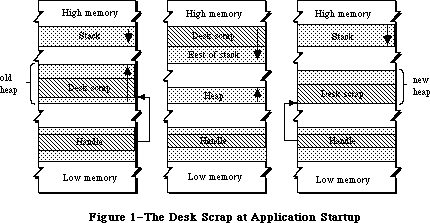 Figure 1–The Desk Scrap at Application Startup
The application can get the size of the desk scrap by calling a Scrap Manager function named InfoScrap. An application concerned about whether there’s room for the desk scrap in memory could be set up so that a small initial segment of the application is loaded in just to check the scrap size. After a decision is made about whether to keep the scrap in memory or on the disk, the remaining segments of the application can be loaded in as needed.
There are certain disadvantages to keeping the desk scrap on the disk. The disk may be locked, it may not have enough room for the scrap, or it may be removed during use of the application. If the application can’t write the scrap to the disk, it should put up an alert box informing the user, who may want to abort the operation at that point.
_______________________________________________________________________________
»DESK SCRAP DATA TYPES
_______________________________________________________________________________
From the user’s point of view there can be only one thing in the Clipboard at a time, but the application may store more than one version of the information in the scrap, each representing the same Clipboard contents in a different form. For example, text cut with a word processor may be stored in the desk scrap both as text and as a QuickDraw picture.
Desk scrap data types, like resource types, are a sequence of four characters. As defined in the Resource Manager, their Pascal type is as follows:
TYPE ResType = PACKED ARRAY[1..4] OF CHAR;
Two standard types of data are defined:
• 'TEXT': a series of ASCII characters
• 'PICT': a QuickDraw picture, which is a saved sequence of drawing
commands that can be played back with the DrawPicture command
and may include picture comments (see the QuickDraw chapter
for details)
Applications must write at least one of these standard types of data to the desk scrap and must be able to read both types. Most applications will prefer one of these types over the other; for example, a word processor prefers text while a graphics application prefers pictures. An application should write at least its preferred standard type of data to the desk scrap, and may write both types (to pass the most information possible on to the receiving application, which may prefer the other type).
An application reading the desk scrap will look for its preferred data type. If its preferred type isn’t there, or if it’s there but was written by an application having a different preferred type, the receiving application may or may not be able to convert the data to the type it needs. If not, some information may be lost in the transfer process. For example, a graphics application can easily convert text to a picture, but the reverse isn’t true. Figure 2 illustrates the latter case: A picture consisting of text is cut from a graphics application, then pasted into a word processor document.
Figure 1–The Desk Scrap at Application Startup
The application can get the size of the desk scrap by calling a Scrap Manager function named InfoScrap. An application concerned about whether there’s room for the desk scrap in memory could be set up so that a small initial segment of the application is loaded in just to check the scrap size. After a decision is made about whether to keep the scrap in memory or on the disk, the remaining segments of the application can be loaded in as needed.
There are certain disadvantages to keeping the desk scrap on the disk. The disk may be locked, it may not have enough room for the scrap, or it may be removed during use of the application. If the application can’t write the scrap to the disk, it should put up an alert box informing the user, who may want to abort the operation at that point.
_______________________________________________________________________________
»DESK SCRAP DATA TYPES
_______________________________________________________________________________
From the user’s point of view there can be only one thing in the Clipboard at a time, but the application may store more than one version of the information in the scrap, each representing the same Clipboard contents in a different form. For example, text cut with a word processor may be stored in the desk scrap both as text and as a QuickDraw picture.
Desk scrap data types, like resource types, are a sequence of four characters. As defined in the Resource Manager, their Pascal type is as follows:
TYPE ResType = PACKED ARRAY[1..4] OF CHAR;
Two standard types of data are defined:
• 'TEXT': a series of ASCII characters
• 'PICT': a QuickDraw picture, which is a saved sequence of drawing
commands that can be played back with the DrawPicture command
and may include picture comments (see the QuickDraw chapter
for details)
Applications must write at least one of these standard types of data to the desk scrap and must be able to read both types. Most applications will prefer one of these types over the other; for example, a word processor prefers text while a graphics application prefers pictures. An application should write at least its preferred standard type of data to the desk scrap, and may write both types (to pass the most information possible on to the receiving application, which may prefer the other type).
An application reading the desk scrap will look for its preferred data type. If its preferred type isn’t there, or if it’s there but was written by an application having a different preferred type, the receiving application may or may not be able to convert the data to the type it needs. If not, some information may be lost in the transfer process. For example, a graphics application can easily convert text to a picture, but the reverse isn’t true. Figure 2 illustrates the latter case: A picture consisting of text is cut from a graphics application, then pasted into a word processor document.
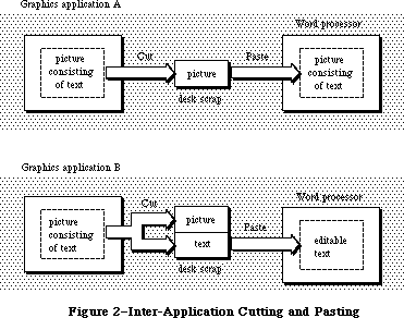 Figure 2–Inter-Application Cutting and Pasting
• If the graphics application writes only its preferred data type (picture)
to the desk scrap—like application A in Figure 2—the text in the
picture will not be editable in the word processor, because it will be
seen as just a series of drawing commands and not as a sequence of
characters.
• On the other hand, if the graphics application takes the trouble to
recognize which characters have been drawn in the picture, and writes
them out to the desk scrap both as a picture and as text—like application
B in Figure 2—the word processor will be able to treat them as editable
text. In this case, however, any part of the picture that isn’t text will
be lost.
In addition to the two standard data types, the desk scrap may also contain application-specific types of data. If several applications are to support the transfer of a private type of data, each one will write and read that type, but still must write at least one of the standard types and be able to read both standard types.
The order in which data is written to the desk scrap is important: The application should write out the different types in order of preference. For example, if it’s a word processor that has a private type of data as its preferred type, but also can write text and pictures, it should write the data in that order.
Since the size of the desk scrap is limited, it may be too costly to write out both an application-specific data type and one (or both) of the standard types. Instead of creating your own type, if your data is graphic, you may be able to use the standard picture type and encode additional information in picture comments. (As described in the QuickDraw chapter, picture comments may be stored in the definition of a picture with the QuickDraw procedure PicComment; they’re passed by the DrawPicture procedure to a special routine set up by the application for that purpose.) Applications that are to process that information can do so, while others can ignore it.
_______________________________________________________________________________
»USING THE SCRAP MANAGER
_______________________________________________________________________________
If you’re concerned about memory use, call InfoScrap early in your program to find out the size of the desk scrap and decide whether there will be enough room in the heap for both the desk scrap and the application itself. If there won’t be enough room for the scrap, call UnloadScrap to write the scrap from memory onto the disk.
InfoScrap also provides a handle to the desk scrap if it’s in memory, its file name on the disk, and a count that changes when the contents of the desk scrap change. If your application supports display of the Clipboard, you can call InfoScrap each time through your main event loop to check this count: If the Clipboard window is visible, it needs to be updated whenever the count changes.
When a Cut or Copy command is given, you need to write the cut or copied data to the desk scrap. First call ZeroScrap to initialize the scrap or clear its previous contents, and then PutScrap to put the data into the scrap. (You can call PutScrap more than once, to put the data in the scrap in different forms.)
Call GetScrap when a Paste command is given, to access data of a particular type in the desk scrap and to get information about the data.
When the user gives a command that terminates the application, call LoadScrap to read the desk scrap back into memory if it’s on the disk (in case the user ejects the disk).
Note: ZeroScrap, PutScrap, and GetScrap all keep track of whether the scrap
is in memory or on the disk, so you don’t have to worry about it.
If your application uses TextEdit and the TextEdit scrap, you’ll need to transfer data between the two scraps, as described in the section “Private Scraps”, below.
_______________________________________________________________________________
»SCRAP MANAGER ROUTINES
_______________________________________________________________________________
Most of these routines return a result code indicating whether an error occurred. If no error occurred, they return the result code
CONST noErr = 0; {no error}
If an error occurred at the Operating System level, an Operating System result code is returned; otherwise, a Scrap Manager result code is returned, as indicated in the routine descriptions. (See Appendix A for a list of all result codes.)
_______________________________________________________________________________
»Getting Desk Scrap Information
FUNCTION InfoScrap : PScrapStuff;
InfoScrap returns a pointer to information about the desk scrap. The PScrapStuff data type is defined as follows:
TYPE PScrapStuff = ^ScrapStuff;
ScrapStuff = RECORD
scrapSize: LONGINT; {size of desk scrap}
scrapHandle: Handle; {handle to desk scrap}
scrapCount: INTEGER; {count changed by ZeroScrap}
scrapState: INTEGER; {tells where desk scrap is}
scrapName: StringPtr {scrap file name}
END;
ScrapSize is the size of the desk scrap in bytes. ScrapHandle is a handle to the scrap if it’s in memory, or NIL if not.
ScrapCount is a count that changes every time ZeroScrap is called. You can use this count for testing whether the contents of the desk scrap have changed, since if ZeroScrap has been called, presumably PutScrap was also called. This may be useful if your application supports display of the Clipboard or has a private scrap (as described under “Private Scraps”, below).
Warning: Just check to see whether the value of the scrapCount field has
changed; don’t rely on exactly how it has changed.
ScrapState is positive if the desk scrap is in memory, 0 if it’s on the disk, or negative if it hasn’t been initialized by ZeroScrap.
Note: ScrapState is actually 0 if the scrap should be on the disk; for
instance, if the user deletes the Clipboard file and then cuts
something, the scrap is really in memory, but ScrapState will be 0.
ScrapName is a pointer to the name of the scrap file, usually “Clipboard File”.
Note: InfoScrap assumes that the scrap file has a version number of 0 and is
on the default volume. (Version numbers and volumes are described in
the File Manager chapter.)
Assembly-language note: The scrap information is available in global variables
that have the same names as the Pascal fields.
_______________________________________________________________________________
»Keeping the Desk Scrap on the Disk
FUNCTION UnloadScrap : LONGINT;
Assembly-language note: The macro you invoke to call UnloadScrap from assembly
language is named _UnlodeScrap.
UnloadScrap writes the desk scrap from memory to the scrap file, and releases the memory it occupied. If the desk scrap is already on the disk, UnloadScrap does nothing. If no error occurs, UnloadScrap returns the result code noErr; otherwise, it returns an Operating System result code indicating an error.
FUNCTION LoadScrap : LONGINT;
Assembly-language note: The macro you invoke to call LoadScrap from assembly
language is named _LodeScrap.
LoadScrap reads the desk scrap from the scrap file into memory. If the desk scrap is already in memory, it does nothing. If no error occurs, LoadScrap returns the result code noErr; otherwise, it returns an Operating System result code indicating an error.
_______________________________________________________________________________
»Writing to the Desk Scrap
FUNCTION ZeroScrap : LONGINT;
If the scrap already exists (in memory or on the disk), ZeroScrap clears its contents; if not, the scrap is initialized in memory. You must call ZeroScrap before the first time you call PutScrap. If no error occurs, ZeroScrap returns the result code noErr; otherwise, it returns an Operating System result code indicating an error.
ZeroScrap also changes the scrapCount field of the record of information provided by InfoScrap.
FUNCTION PutScrap (length: LONGINT; theType: ResType;
source: Ptr) : LONGINT;
PutScrap writes the data pointed to by the source parameter to the desk scrap
(in memory or on the disk). The length parameter indicates the number of bytes to write, and theType is the data type.
Warning: The specified type must be different from the type of any data
already in the desk scrap. If you write data of a type already in
the scrap, the new data will be appended to the scrap, and subsequent
GetScrap calls will still return the old data.
If no error occurs, PutScrap returns the result code noErr; otherwise, it returns an Operating System result code indicating an error, or the following Scrap Manager result code:
CONST noScrapErr = -100; {desk scrap isn't initialized}
Warning: Don’t forget to call ZeroScrap to initialize the scrap or clear its
previous contents.
Note: To copy the TextEdit scrap to the desk scrap, use the TextEdit function
TEToScrap.
_______________________________________________________________________________
»Reading from the Desk Scrap
FUNCTION GetScrap (hDest: Handle; theType: ResType;
VAR offset: LONGINT) : LONGINT;
Given an existing handle in hDest, GetScrap reads the data of type theType from the desk scrap (whether in memory or on the disk), makes a copy of it in memory, and sets hDest to be a handle to the copy. Usually you’ll pass in hDest a handle to a minimum-size block; GetScrap will resize the block and copy the scrap into it. If you pass NIL in hDest, GetScrap will not read in the data. This is useful if you want to be sure the data is there before allocating space for its handle, or if you just want to know the size of the data.
In the offset parameter, GetScrap returns the location of the data as an offset (in bytes) from the beginning of the desk scrap. If no error occurs, the function result is the length of the data in bytes; otherwise, it’s either an appropriate Operating System result code (which will be negative) or the following Scrap Manager result code:
CONST noTypeErr = -102; {no data of the requested type}
For example, given the declarations
VAR pHndl: Handle; {handle for 'PICT' type}
tHndl: Handle; {handle for 'TEXT' type}
length: LONGINT;
offset: LONGINT;
frame: Rect;
you can make the following calls:
pHndl := NewHandle(0);
length := GetScrap(pHndl,'PICT',offset);
IF length < 0
THEN
{error handling}
ELSE DrawPicture(PicHandle(pHndl),frame)
If your application wants data in the form of a picture, and the scrap contains only text, you can convert the text into a picture by doing the following:
tHndl := NewHandle(0);
length := GetScrap(tHndl,'TEXT',offset);
IF length < 0
THEN
{error handling}
ELSE
BEGIN
HLock(tHndl);
pHndl := OpenPicture(thePort^.portRect);
TextBox(tHndl^,length,thePort^.portRect,teJustLeft);
ClosePicture;
HUnlock(tHndl);
END
The Memory Manager procedures HLock and HUnlock are used to lock and unlock blocks when handles are dereferenced (see the Memory Manager chapter).
Note: To copy the desk scrap to the TextEdit scrap, use the TextEdit
function TEFromScrap.
Your application should pass its preferred data type to GetScrap. If it doesn’t prefer one data type over any other, it should try getting each of the types it can read, and use the type that returns the lowest offset. (A lower offset means that this data type was written before the others, and therefore was preferred by the application that wrote it.)
Note: If you’re trying to read in a complicated picture, and there isn’t
enough room in memory for a copy of it, you can customize QuickDraw’s
picture retrieval so that DrawPicture will read the picture directly
from the scrap file. (QuickDraw also lets you customize how pictures
are saved so you can save them in a file; see the QuickDraw chapter
for details about customizing.)
Note: When reading in a picture from the scrap, allow a buffer of about 3.5K
bytes on the stack.
_______________________________________________________________________________
»PRIVATE SCRAPS
_______________________________________________________________________________
Note: MultiFinder keeps separate scrap variables for each partition. For
more information about managing private scraps with MultiFinder running,
refer to the “Programmer’s Guide to MultiFinder” and Technical Notes
#180 and #205.
X-Ref: Technical Note #180
X-Ref: Technical Note #205
Instead of using the desk scrap for storing data that’s cut and pasted within an application, advanced programmers may want to set up a private scrap for this purpose. In applications that use the standard 'TEXT' or 'PICT' data types, it’s simpler to use the desk scrap, but if your application defines its own private type of data, or if it’s likely that very large amounts of data will be cut and pasted, using a private scrap may result in faster cutting and pasting within the application.
The format of a private scrap can be whatever the application likes, since no other application will use it. For example, an application can simply maintain a pointer to data that’s been cut or copied. The application must, however, be able to convert data between the format of its private scrap and the format of the desk scrap.
Note: The TextEdit scrap is a private scrap for applications that use TextEdit.
TextEdit provides routines for accessing this scrap; you’ll need to
transfer data between the TextEdit scrap and the desk scrap.
If you use a private scrap, you must be sure that the right data will always be pasted when the user gives a Paste command (the right data being whatever was most recently cut or copied in any application or desk accessory), and that the Clipboard, if visible, always shows the current data. You should copy the contents of the desk scrap to your private scrap at application startup and whenever a desk accessory is deactivated (call GetScrap to access the desk scrap). When the application is terminated or when a desk accessory is activated, you should copy the contents of the private scrap to the desk scrap: Call ZeroScrap to initialize the desk scrap or clear its previous contents, and PutScrap to write data to the desk scrap.
If transferring data between the two scraps means converting it, and possibly losing information, you can copy the scrap only when you actually need to, at the time something is cut or pasted. The desk scrap needn’t be copied to the private scrap unless a Paste command is given before the first Cut or Copy command since the application started up or since a desk accessory that changed the scrap was deactivated. Until that point, you must keep the contents of the desk scrap intact, displaying it instead of the private scrap in the Clipboard window if that window is visible. Thereafter, you can ignore the desk scrap until a desk accessory is activated or the application is terminated; in either of these cases, you must copy the private scrap back to the desk scrap. Thus whatever was last cut or copied within the application will be pasted if a Paste command is given in a desk accessory or in the next application. If no Cut or Copy commands are given within the application, you never have to change the desk scrap.
To find out whether a desk accessory has changed the desk scrap, you can check the scrapCount field of the record returned by InfoScrap. Save the value of this field when one of your application’s windows is deactivated and a system window is activated. Check each time through the main event loop to see whether its value has changed; if so, the contents of the desk scrap have changed.
If the application encounters problems in trying to copy one scrap to another, it should alert the user. The desk scrap may be too large to copy to the private scrap, in which case the user may want to leave the application or just proceed with an empty Clipboard. If the private scrap is too large to copy to the desk scrap, either because it’s disk-based and too large to copy into memory or because it exceeds the maximum size allowed for the desk scrap, the user may want to stay in the application and cut or copy something smaller.
_______________________________________________________________________________
»FORMAT OF THE DESK SCRAP
_______________________________________________________________________________
In general, the desk scrap consists of a series of data items that have the following format:
Number of bytes Contents
4 bytes Type (a sequence of four characters)
4 bytes Length of following data in bytes
n bytes Data; n must be even (if the above length
is odd, add an extra byte)
The standard types are 'TEXT' and 'PICT'. You may use any other four-character sequence for types specific to your application.
The format of the data for the 'TEXT' type is as follows:
Number of bytes Contents
4 bytes Number of characters in the text
n bytes The characters in the text
The data for the 'PICT' type is a QuickDraw picture, which consists of the size of the picture in bytes, the picture frame, and the picture definition data
(which may include picture comments). See the QuickDraw chapter for details.
_______________________________________________________________________________
»SUMMARY OF THE SCRAP MANAGER
_______________________________________________________________________________
Constants
CONST
{ Scrap Manager result codes }
noScrapErr = -100; {desk scrap isn't initialized}
noTypeErr = -102; {no data of the requested type}
_______________________________________________________________________________
Data Types
TYPE
PScrapStuff = ^ScrapStuff;
ScrapStuff = RECORD
scrapSize: LONGINT; {size of desk scrap}
scrapHandle: Handle; {handle to desk scrap}
scrapCount: INTEGER; {count changed by ZeroScrap}
scrapState: INTEGER; {tells where desk scrap is}
scrapName: StringPtr {scrap file name}
END;
_______________________________________________________________________________
Routines
Getting Desk Scrap Information
FUNCTION InfoScrap : PScrapStuff;
Keeping the Desk Scrap on the Disk
FUNCTION UnloadScrap : LONGINT;
FUNCTION LoadScrap : LONGINT;
Writing to the Desk Scrap
FUNCTION ZeroScrap : LONGINT;
FUNCTION PutScrap (length: LONGINT; theType: ResType;
source: Ptr) : LONGINT;
Reading from the Desk Scrap
FUNCTION GetScrap (hDest: Handle; theType: ResType;
VAR offset: LONGINT) : LONGINT;
_______________________________________________________________________________
Assembly-Language Information
Constants
; Scrap Manager result codes
noScrapErr .EQU -100 ;desk scrap isn't initialized
noTypeErr .EQU -102 ;no data of the requested type
Special Macro Names
Pascal name Macro name
LoadScrap _LodeScrap
UnloadScrap _UnlodeScrap
Variables
ScrapSize Size in bytes of desk scrap (long)
ScrapHandle Handle to desk scrap in memory
ScrapCount Count changed by ZeroScrap (word)
ScrapState Tells where desk scrap is (word)
ScrapName Pointer to scrap file name (preceded by length byte)
Further Reference:
_______________________________________________________________________________
Resource Manager
QuickDraw
Toolbox Event Manager
Technical Note #180, MultiFinder Miscellanea
Technical Note #205, MultiFinder Revisited: The 6.0 System Release
Figure 2–Inter-Application Cutting and Pasting
• If the graphics application writes only its preferred data type (picture)
to the desk scrap—like application A in Figure 2—the text in the
picture will not be editable in the word processor, because it will be
seen as just a series of drawing commands and not as a sequence of
characters.
• On the other hand, if the graphics application takes the trouble to
recognize which characters have been drawn in the picture, and writes
them out to the desk scrap both as a picture and as text—like application
B in Figure 2—the word processor will be able to treat them as editable
text. In this case, however, any part of the picture that isn’t text will
be lost.
In addition to the two standard data types, the desk scrap may also contain application-specific types of data. If several applications are to support the transfer of a private type of data, each one will write and read that type, but still must write at least one of the standard types and be able to read both standard types.
The order in which data is written to the desk scrap is important: The application should write out the different types in order of preference. For example, if it’s a word processor that has a private type of data as its preferred type, but also can write text and pictures, it should write the data in that order.
Since the size of the desk scrap is limited, it may be too costly to write out both an application-specific data type and one (or both) of the standard types. Instead of creating your own type, if your data is graphic, you may be able to use the standard picture type and encode additional information in picture comments. (As described in the QuickDraw chapter, picture comments may be stored in the definition of a picture with the QuickDraw procedure PicComment; they’re passed by the DrawPicture procedure to a special routine set up by the application for that purpose.) Applications that are to process that information can do so, while others can ignore it.
_______________________________________________________________________________
»USING THE SCRAP MANAGER
_______________________________________________________________________________
If you’re concerned about memory use, call InfoScrap early in your program to find out the size of the desk scrap and decide whether there will be enough room in the heap for both the desk scrap and the application itself. If there won’t be enough room for the scrap, call UnloadScrap to write the scrap from memory onto the disk.
InfoScrap also provides a handle to the desk scrap if it’s in memory, its file name on the disk, and a count that changes when the contents of the desk scrap change. If your application supports display of the Clipboard, you can call InfoScrap each time through your main event loop to check this count: If the Clipboard window is visible, it needs to be updated whenever the count changes.
When a Cut or Copy command is given, you need to write the cut or copied data to the desk scrap. First call ZeroScrap to initialize the scrap or clear its previous contents, and then PutScrap to put the data into the scrap. (You can call PutScrap more than once, to put the data in the scrap in different forms.)
Call GetScrap when a Paste command is given, to access data of a particular type in the desk scrap and to get information about the data.
When the user gives a command that terminates the application, call LoadScrap to read the desk scrap back into memory if it’s on the disk (in case the user ejects the disk).
Note: ZeroScrap, PutScrap, and GetScrap all keep track of whether the scrap
is in memory or on the disk, so you don’t have to worry about it.
If your application uses TextEdit and the TextEdit scrap, you’ll need to transfer data between the two scraps, as described in the section “Private Scraps”, below.
_______________________________________________________________________________
»SCRAP MANAGER ROUTINES
_______________________________________________________________________________
Most of these routines return a result code indicating whether an error occurred. If no error occurred, they return the result code
CONST noErr = 0; {no error}
If an error occurred at the Operating System level, an Operating System result code is returned; otherwise, a Scrap Manager result code is returned, as indicated in the routine descriptions. (See Appendix A for a list of all result codes.)
_______________________________________________________________________________
»Getting Desk Scrap Information
FUNCTION InfoScrap : PScrapStuff;
InfoScrap returns a pointer to information about the desk scrap. The PScrapStuff data type is defined as follows:
TYPE PScrapStuff = ^ScrapStuff;
ScrapStuff = RECORD
scrapSize: LONGINT; {size of desk scrap}
scrapHandle: Handle; {handle to desk scrap}
scrapCount: INTEGER; {count changed by ZeroScrap}
scrapState: INTEGER; {tells where desk scrap is}
scrapName: StringPtr {scrap file name}
END;
ScrapSize is the size of the desk scrap in bytes. ScrapHandle is a handle to the scrap if it’s in memory, or NIL if not.
ScrapCount is a count that changes every time ZeroScrap is called. You can use this count for testing whether the contents of the desk scrap have changed, since if ZeroScrap has been called, presumably PutScrap was also called. This may be useful if your application supports display of the Clipboard or has a private scrap (as described under “Private Scraps”, below).
Warning: Just check to see whether the value of the scrapCount field has
changed; don’t rely on exactly how it has changed.
ScrapState is positive if the desk scrap is in memory, 0 if it’s on the disk, or negative if it hasn’t been initialized by ZeroScrap.
Note: ScrapState is actually 0 if the scrap should be on the disk; for
instance, if the user deletes the Clipboard file and then cuts
something, the scrap is really in memory, but ScrapState will be 0.
ScrapName is a pointer to the name of the scrap file, usually “Clipboard File”.
Note: InfoScrap assumes that the scrap file has a version number of 0 and is
on the default volume. (Version numbers and volumes are described in
the File Manager chapter.)
Assembly-language note: The scrap information is available in global variables
that have the same names as the Pascal fields.
_______________________________________________________________________________
»Keeping the Desk Scrap on the Disk
FUNCTION UnloadScrap : LONGINT;
Assembly-language note: The macro you invoke to call UnloadScrap from assembly
language is named _UnlodeScrap.
UnloadScrap writes the desk scrap from memory to the scrap file, and releases the memory it occupied. If the desk scrap is already on the disk, UnloadScrap does nothing. If no error occurs, UnloadScrap returns the result code noErr; otherwise, it returns an Operating System result code indicating an error.
FUNCTION LoadScrap : LONGINT;
Assembly-language note: The macro you invoke to call LoadScrap from assembly
language is named _LodeScrap.
LoadScrap reads the desk scrap from the scrap file into memory. If the desk scrap is already in memory, it does nothing. If no error occurs, LoadScrap returns the result code noErr; otherwise, it returns an Operating System result code indicating an error.
_______________________________________________________________________________
»Writing to the Desk Scrap
FUNCTION ZeroScrap : LONGINT;
If the scrap already exists (in memory or on the disk), ZeroScrap clears its contents; if not, the scrap is initialized in memory. You must call ZeroScrap before the first time you call PutScrap. If no error occurs, ZeroScrap returns the result code noErr; otherwise, it returns an Operating System result code indicating an error.
ZeroScrap also changes the scrapCount field of the record of information provided by InfoScrap.
FUNCTION PutScrap (length: LONGINT; theType: ResType;
source: Ptr) : LONGINT;
PutScrap writes the data pointed to by the source parameter to the desk scrap
(in memory or on the disk). The length parameter indicates the number of bytes to write, and theType is the data type.
Warning: The specified type must be different from the type of any data
already in the desk scrap. If you write data of a type already in
the scrap, the new data will be appended to the scrap, and subsequent
GetScrap calls will still return the old data.
If no error occurs, PutScrap returns the result code noErr; otherwise, it returns an Operating System result code indicating an error, or the following Scrap Manager result code:
CONST noScrapErr = -100; {desk scrap isn't initialized}
Warning: Don’t forget to call ZeroScrap to initialize the scrap or clear its
previous contents.
Note: To copy the TextEdit scrap to the desk scrap, use the TextEdit function
TEToScrap.
_______________________________________________________________________________
»Reading from the Desk Scrap
FUNCTION GetScrap (hDest: Handle; theType: ResType;
VAR offset: LONGINT) : LONGINT;
Given an existing handle in hDest, GetScrap reads the data of type theType from the desk scrap (whether in memory or on the disk), makes a copy of it in memory, and sets hDest to be a handle to the copy. Usually you’ll pass in hDest a handle to a minimum-size block; GetScrap will resize the block and copy the scrap into it. If you pass NIL in hDest, GetScrap will not read in the data. This is useful if you want to be sure the data is there before allocating space for its handle, or if you just want to know the size of the data.
In the offset parameter, GetScrap returns the location of the data as an offset (in bytes) from the beginning of the desk scrap. If no error occurs, the function result is the length of the data in bytes; otherwise, it’s either an appropriate Operating System result code (which will be negative) or the following Scrap Manager result code:
CONST noTypeErr = -102; {no data of the requested type}
For example, given the declarations
VAR pHndl: Handle; {handle for 'PICT' type}
tHndl: Handle; {handle for 'TEXT' type}
length: LONGINT;
offset: LONGINT;
frame: Rect;
you can make the following calls:
pHndl := NewHandle(0);
length := GetScrap(pHndl,'PICT',offset);
IF length < 0
THEN
{error handling}
ELSE DrawPicture(PicHandle(pHndl),frame)
If your application wants data in the form of a picture, and the scrap contains only text, you can convert the text into a picture by doing the following:
tHndl := NewHandle(0);
length := GetScrap(tHndl,'TEXT',offset);
IF length < 0
THEN
{error handling}
ELSE
BEGIN
HLock(tHndl);
pHndl := OpenPicture(thePort^.portRect);
TextBox(tHndl^,length,thePort^.portRect,teJustLeft);
ClosePicture;
HUnlock(tHndl);
END
The Memory Manager procedures HLock and HUnlock are used to lock and unlock blocks when handles are dereferenced (see the Memory Manager chapter).
Note: To copy the desk scrap to the TextEdit scrap, use the TextEdit
function TEFromScrap.
Your application should pass its preferred data type to GetScrap. If it doesn’t prefer one data type over any other, it should try getting each of the types it can read, and use the type that returns the lowest offset. (A lower offset means that this data type was written before the others, and therefore was preferred by the application that wrote it.)
Note: If you’re trying to read in a complicated picture, and there isn’t
enough room in memory for a copy of it, you can customize QuickDraw’s
picture retrieval so that DrawPicture will read the picture directly
from the scrap file. (QuickDraw also lets you customize how pictures
are saved so you can save them in a file; see the QuickDraw chapter
for details about customizing.)
Note: When reading in a picture from the scrap, allow a buffer of about 3.5K
bytes on the stack.
_______________________________________________________________________________
»PRIVATE SCRAPS
_______________________________________________________________________________
Note: MultiFinder keeps separate scrap variables for each partition. For
more information about managing private scraps with MultiFinder running,
refer to the “Programmer’s Guide to MultiFinder” and Technical Notes
#180 and #205.
X-Ref: Technical Note #180
X-Ref: Technical Note #205
Instead of using the desk scrap for storing data that’s cut and pasted within an application, advanced programmers may want to set up a private scrap for this purpose. In applications that use the standard 'TEXT' or 'PICT' data types, it’s simpler to use the desk scrap, but if your application defines its own private type of data, or if it’s likely that very large amounts of data will be cut and pasted, using a private scrap may result in faster cutting and pasting within the application.
The format of a private scrap can be whatever the application likes, since no other application will use it. For example, an application can simply maintain a pointer to data that’s been cut or copied. The application must, however, be able to convert data between the format of its private scrap and the format of the desk scrap.
Note: The TextEdit scrap is a private scrap for applications that use TextEdit.
TextEdit provides routines for accessing this scrap; you’ll need to
transfer data between the TextEdit scrap and the desk scrap.
If you use a private scrap, you must be sure that the right data will always be pasted when the user gives a Paste command (the right data being whatever was most recently cut or copied in any application or desk accessory), and that the Clipboard, if visible, always shows the current data. You should copy the contents of the desk scrap to your private scrap at application startup and whenever a desk accessory is deactivated (call GetScrap to access the desk scrap). When the application is terminated or when a desk accessory is activated, you should copy the contents of the private scrap to the desk scrap: Call ZeroScrap to initialize the desk scrap or clear its previous contents, and PutScrap to write data to the desk scrap.
If transferring data between the two scraps means converting it, and possibly losing information, you can copy the scrap only when you actually need to, at the time something is cut or pasted. The desk scrap needn’t be copied to the private scrap unless a Paste command is given before the first Cut or Copy command since the application started up or since a desk accessory that changed the scrap was deactivated. Until that point, you must keep the contents of the desk scrap intact, displaying it instead of the private scrap in the Clipboard window if that window is visible. Thereafter, you can ignore the desk scrap until a desk accessory is activated or the application is terminated; in either of these cases, you must copy the private scrap back to the desk scrap. Thus whatever was last cut or copied within the application will be pasted if a Paste command is given in a desk accessory or in the next application. If no Cut or Copy commands are given within the application, you never have to change the desk scrap.
To find out whether a desk accessory has changed the desk scrap, you can check the scrapCount field of the record returned by InfoScrap. Save the value of this field when one of your application’s windows is deactivated and a system window is activated. Check each time through the main event loop to see whether its value has changed; if so, the contents of the desk scrap have changed.
If the application encounters problems in trying to copy one scrap to another, it should alert the user. The desk scrap may be too large to copy to the private scrap, in which case the user may want to leave the application or just proceed with an empty Clipboard. If the private scrap is too large to copy to the desk scrap, either because it’s disk-based and too large to copy into memory or because it exceeds the maximum size allowed for the desk scrap, the user may want to stay in the application and cut or copy something smaller.
_______________________________________________________________________________
»FORMAT OF THE DESK SCRAP
_______________________________________________________________________________
In general, the desk scrap consists of a series of data items that have the following format:
Number of bytes Contents
4 bytes Type (a sequence of four characters)
4 bytes Length of following data in bytes
n bytes Data; n must be even (if the above length
is odd, add an extra byte)
The standard types are 'TEXT' and 'PICT'. You may use any other four-character sequence for types specific to your application.
The format of the data for the 'TEXT' type is as follows:
Number of bytes Contents
4 bytes Number of characters in the text
n bytes The characters in the text
The data for the 'PICT' type is a QuickDraw picture, which consists of the size of the picture in bytes, the picture frame, and the picture definition data
(which may include picture comments). See the QuickDraw chapter for details.
_______________________________________________________________________________
»SUMMARY OF THE SCRAP MANAGER
_______________________________________________________________________________
Constants
CONST
{ Scrap Manager result codes }
noScrapErr = -100; {desk scrap isn't initialized}
noTypeErr = -102; {no data of the requested type}
_______________________________________________________________________________
Data Types
TYPE
PScrapStuff = ^ScrapStuff;
ScrapStuff = RECORD
scrapSize: LONGINT; {size of desk scrap}
scrapHandle: Handle; {handle to desk scrap}
scrapCount: INTEGER; {count changed by ZeroScrap}
scrapState: INTEGER; {tells where desk scrap is}
scrapName: StringPtr {scrap file name}
END;
_______________________________________________________________________________
Routines
Getting Desk Scrap Information
FUNCTION InfoScrap : PScrapStuff;
Keeping the Desk Scrap on the Disk
FUNCTION UnloadScrap : LONGINT;
FUNCTION LoadScrap : LONGINT;
Writing to the Desk Scrap
FUNCTION ZeroScrap : LONGINT;
FUNCTION PutScrap (length: LONGINT; theType: ResType;
source: Ptr) : LONGINT;
Reading from the Desk Scrap
FUNCTION GetScrap (hDest: Handle; theType: ResType;
VAR offset: LONGINT) : LONGINT;
_______________________________________________________________________________
Assembly-Language Information
Constants
; Scrap Manager result codes
noScrapErr .EQU -100 ;desk scrap isn't initialized
noTypeErr .EQU -102 ;no data of the requested type
Special Macro Names
Pascal name Macro name
LoadScrap _LodeScrap
UnloadScrap _UnlodeScrap
Variables
ScrapSize Size in bytes of desk scrap (long)
ScrapHandle Handle to desk scrap in memory
ScrapCount Count changed by ZeroScrap (word)
ScrapState Tells where desk scrap is (word)
ScrapName Pointer to scrap file name (preceded by length byte)
Further Reference:
_______________________________________________________________________________
Resource Manager
QuickDraw
Toolbox Event Manager
Technical Note #180, MultiFinder Miscellanea
Technical Note #205, MultiFinder Revisited: The 6.0 System Release
The Script Manager
_______________________________________________________________________________
THE SCRIPT MANAGER
_______________________________________________________________________________
About This Chapter
About the Script Manager
Text Manipulation
Determining the Script in Use
Drawing and Measuring
Parsing
Character Codes
Key-Down Event Handling
Writing Direction
Partitioning Text
Numeric Strings
Using the Script Manager
Script Information
Character Information
Text Editing
Advanced Routines
System Routines
'Itl4' Resource
Script Manager Routines
CharByte
CharType
Pixel2Char
Char2Pixel
FindWord
HiLiteText
DrawJust
MeasureJust
Transliterate
GetScript
SetScript
GetEnvirons
SetEnvirons
FontScript
IntlScript
KeyScript
Font2Script
GetDefFontSize
GetSysFont
GetAppFont
GetMBarHeight
GetSysJust
SetSysJust
Script Manager 2.0 Routines
ParseTable
IntlTokenize
PortionText
FormatOrder
FindScriptRun
StyledLineBreak
VisibleLength
UprText and LwrText
Text Comparison
LongDateTime
InitDateCache
String2Date and String2Time
LongDate2Secs and LongSecs2Date
ToggleDate and ValidDate
ReadLocation and WriteLocation
Setting Latitude, Longitude, and Time Zone cdev
NumberParts
Str2Format
Format2Str
FormatX2Str
FormatStr2X
Hints for Using the Script Manager
Testing for the Script Manager
Setting the Keyboard Script
Summary of the Script Manager
_______________________________________________________________________________
»ABOUT THIS CHAPTER
_______________________________________________________________________________
This chapter describes the Script Manager, a set of general text manipulation routines that let applications function correctly with non-Roman writing systems such as Japanese and Arabic, as well as Roman (or Latin-based) alphabets such as English, French, and German. The Script Manager works with one or more Script Interface Systems, each of which contains the rules for a specific method of writing.
This chapter also documents version 2.0 of the Script Manager. It includes extended date and time utility routines, general-purpose number formatting routines, and additional text manipulation routines.
Reader’s guide: Most applications do not need to call the Script Manager
routines directly, since they can handle text by means of
TextEdit, which functions correctly with the Script Manager.
Applications that need to call the new routines are those
that directly manipulate text, such as word processors or
programs that parse ordinary language.
You should already be familiar with
• QuickDraw’s text manipulation functions
• the International Utilities package
• the Binary-Decimal Conversion package
It may also be helpful to have a general understanding of how the Font Manager provides font support for QuickDraw and how TextEdit handles word selection and justification.
The process of adapting an application to different languages, called localization, is made easier if certain principles are kept in mind when you create the application. For example, you should place quoted strings in resources separate from program code, and you should avoid implicit assumptions about the language that the application uses, such as the number of characters in its alphabet. General guidelines for writing applications that are easy to localize are presented in Human Interface Guidelines, available through APDA. They are summarized in the “Compatibility Guidelines” chapter.
_______________________________________________________________________________
»ABOUT THE SCRIPT MANAGER
_______________________________________________________________________________
The Script Manager is a set of extensions to the standard Macintosh Toolbox and operating system that does two things:
• It provides standard, easy-to-use tools for the sophisticated
manipulation of ordinary text.
• It makes it easy to translate an application into another writing system.
A script is a writing system. Roman scripts are writing systems whose alphabets have evolved from Latin. Non-Roman scripts, (such as Japanese, Chinese, and Arabic) have quite different characteristics. For example, Roman scripts generally have less than 256 characters, whereas the Japanese script contains more than 40,000. Characters of Roman scripts are relatively independent of each other, but Arabic characters change form depending on surrounding characters.
For example, Figure 1 shows how Key Caps looks in Arabic script.
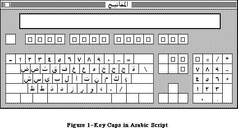 Figure 1–Key Caps in Arabic Script
The Script Manager is the low-level software that enables Macintosh applications to work with such different scripts. It includes utilities and initialization code to create an environment in which scripts of all kinds can be handled. In order for an application to use a particular script, a Script Interface System to support that script must also be present. All the currently available Script Interface Systems are written by Apple. Macintosh computers normally use the Roman script, so the Roman Interface System (RIS) is in the System file and always present. On some models it may be in ROM. Other Script Interface Systems are the Kanji Interface System (KIS, also called KanjiTalk), which allows applications to write in Japanese; the Arabic Interface System (AIS); and the Hanze Interface System (HIS) for Chinese.
A Script Interface System typically provides the following:
• fonts for the target language
• keyboard mapping tables
• special routines to perform character input, conversion,
sorting, and text manipulation
• a desk accessory utility for system maintenance and control
The Script Manager calls a Script Interface System to perform specific procedure calls for a given script. How a typical call (in this case, Pixel2Char) is passed from an application through the Script Manager to a Script Interface System and back is shown in Figure 2.
Figure 1–Key Caps in Arabic Script
The Script Manager is the low-level software that enables Macintosh applications to work with such different scripts. It includes utilities and initialization code to create an environment in which scripts of all kinds can be handled. In order for an application to use a particular script, a Script Interface System to support that script must also be present. All the currently available Script Interface Systems are written by Apple. Macintosh computers normally use the Roman script, so the Roman Interface System (RIS) is in the System file and always present. On some models it may be in ROM. Other Script Interface Systems are the Kanji Interface System (KIS, also called KanjiTalk), which allows applications to write in Japanese; the Arabic Interface System (AIS); and the Hanze Interface System (HIS) for Chinese.
A Script Interface System typically provides the following:
• fonts for the target language
• keyboard mapping tables
• special routines to perform character input, conversion,
sorting, and text manipulation
• a desk accessory utility for system maintenance and control
The Script Manager calls a Script Interface System to perform specific procedure calls for a given script. How a typical call (in this case, Pixel2Char) is passed from an application through the Script Manager to a Script Interface System and back is shown in Figure 2.
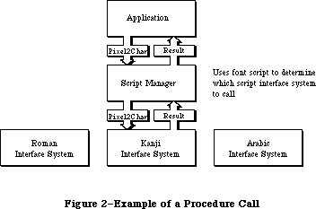 Figure 2–Example of a Procedure Call
In many cases the versatility provided by Script Interface Systems allows applications to be localized for non-Roman languages with no change to their program code (assuming they were written to permit localization to Roman script. Up to 64 different Script Interface Systems can be installed at one time on the Macintosh, allowing an application to switch back and forth between different scripts. When more than one Script Interface System is installed, an icon symbolizing the script in use appears at the right side of the menu bar.
The Script Manager provides the functions needed to extend Macintosh’s text manipulation capabilities beyond any implicit assumptions that would limit it to Roman scripts. The areas in which these limitations appear are:
• Character set size. Large character sets, such as Japanese, require
two-byte codes for computer storage in place of the one-byte codes that
are sufficient for Roman scripts. Script Manager routines permit
applications to run without knowing whether one-byte or two-byte codes
are being used.
• Writing direction. The Script Manager provides the capability to write
from right to left, as required by Arabic, Hebrew, and other languages,
and to mix right-to-left and left-to-right directions within lines and
blocks of text.
• Context dependence. Context dependence means that characters may be
modified by the values of preceding and following characters in the input
stream. In Arabic, for example, many characters change form depending on
other characters nearby. Context analysis is usually handled by the
appropriate Script Interface System under the control of the Script
Manager.
• Word demarcation. Words in Roman scripts are generally delimited by
spaces and punctuation marks. In contrast, Japanese scripts may have no
word delimiters, so the Script Manager provides a more sophisticated
method of finding word boundaries. TextEdit calls may be intercepted by
the Script Manager, which calls the appropriate Script Interface System
routines to perform selection, highlighting, dragging, and word wrapping
correctly for the current script.
• Text justification. Justification (spreading text out to fill a given
line width) is usually performed in Roman text by increasing the size of
the interword spaces. Arabic, however, inserts extension bar characters
between joined characters and widens blank characters to fill any
remaining gap. The Script Manager provides routines that take these
alternate justification methods into account when drawing, measuring, or
selecting text.
The Script Manager 2.0 release extends the tools and capabilities of developers on the Macintosh for three areas: text, dates and numbers. In addition, some minor bugs were fixed and performance enhancements incorporated.
The new text routines include: lexically interpreting different scripts (e.g., in macro languages); allotting justification to different format runs within a line; ordering format runs properly with bidirectional text (Hebrew & Arabic); quickly separating Roman from non-Roman text, and determining word-wrap in text processing. The international utilities text comparison routines were significantly improved in performance, in amounts ranging from 25% to 94%.
The Macintosh date routines are extended to provide a larger range (roughly 35 thousand years), and more information. This extension allows programs that need a larger range of dates to use system routines rather than produce their own, which may not be internationally compatible. The programmer can also access the stored location (latitude and longitude) and time zone of the Macintosh from parameter RAM. The Map cdev gives users the ability to change and reference these values.
The new number routines supplement SANE, allowing applications to display formatted numbers in the manner of Microsoft Excel or Fourth Dimension, and to read both formatted and simple numbers. The formatting strings allow natural display and entry of numbers and editing of format strings even though the original numbers and the format strings were entered in a language other than that of the final user.
Some of the following 2.0 routines have parameter blocks with reserved fields. These fields must be zeroed.
In general, the additional routines are handled by the Script Manager rather than script interface systems. The three exceptions are FindScriptRun, PortionText, and VisibleLength which are handled by the individual script systems (such as Roman). The version of the Script Manager can be checked before using any of these routines, to make sure that it is Script Manager 2.0
(version is $0200 or greater). For compatibility, all Script Systems test the version of the Script Manager and do not initialize if the major version number (first byte) is greater than they expect.
For testing only, the version number in INIT 2 can be changed in ResEdit in the resource header to enable those systems to run; the header has the following format:
60xx Branch
xxxx Flags word
4943 Resource type (INIT)
4954
0002 Resource number (2)
02xx Script Manager version: change to 01FF for testing
For an old script, the three routines FindScriptRun, PortionText, and VisibleLength will not work at all. In addition, the 'itl4' resource (see below) for the script will not be present, so the IntlTokenize and number formatting routines will not work properly for the particular script’s features.
The results returned from the new function calls are error and status codes which are found in the MPW 3.0 header and interface files.
Note that in the following text, the term “language” generally refers to a natural language rather than a programming language.
The interface files for the Script Manager 2.0 routines are available in MPW 3.0 and later releases.
_______________________________________________________________________________
»TEXT MANIPULATION
_______________________________________________________________________________
Applications that do extensive text handling and analysis, such as word processors, may need to use Script Manager routines directly and work in close interaction with Script Interface Systems. This section describes some potential problems with such applications and provides general guidelines for handling them.
_______________________________________________________________________________
»Determining the Script in Use
The characteristics of different scripts require that text manipulation functions be handled according to the script in use. Every script has a unique identification number, as shown in the following list:
Constant Value Script
smRoman 0 Normal ASCII alphabet
smKanji 1 Japanese
smChinese 2 Chinese
smKorean 3 Korean
smArabic 4 Arabic
smHebrew 5 Hebrew
smGreek 6 Greek
smRussian 7 Cyrillic
smReserved1 8 Reserved
smDevanagari 9 Devanagari
smGurmukhi 10 Gurmukhi
smGujarati 11 Gujarati
smOriya 12 Oriya
smBengali 13 Bengali
smTamil 14 Tamil
smTelugu 15 Telugu
smKannada 16 Kannada
smMalayalam 17 Malayalam
smSinhalese 18 Sinhalese
smBurmese 19 Burmese
smKhmer 20 Cambodian
smThai 21 Thai
smLaotian 22 Laotian
smGeorgian 23 Georgian
smArmenian 24 Armenian
smMaldivian 25 Maldivian
smTibetan 26 Tibetan
smMongolian 27 Mongolian
smAmharic 28 Ethiopian
smSlavic 29 Non-Cyrillic Slavic
smVietnamese 30 Vietnamese
smSindhi 31 Sindhi
smUninterp 32 Uninterpreted symbols (such as MacPaint palette symbols)
The Script Manager looks for one of these values in the font field of the current grafPort (thePort) to determine which script the application is using. The script specified by the font of thePort is referred to as the font script. For example, if thePort’s font is Geneva, the font script will be Roman. If thePort’s font is Kyoto, the font script will be Japanese. If the mapping from font to script results in a request for a Script Interface System that is not available, the font script defaults to Roman.
Note: Be sure to set the font in the current grafPort correctly so the Script
Manager will know what script it is working with. Otherwise the results
it returns will be meaningless (for example, if a block of Arabic text
is treated as if it were kanji).
The font script is not to be confused with the key script, which is maintained by the system. The key script value determines which keyboard layout and input method to use, but has no effect on characters drawn on the screen or on the operations performed by the Script Manager routines. The key and font scripts are not always the same. For example, while an international word processing application is using the Arabic Interface System for keyboard input, it may also be drawing kanji and Roman text on the screen. For further information about keyboard characters translation, see the System Resource File chapter.
_______________________________________________________________________________
»Drawing and Measuring
The drawing and measuring of Roman and non-Roman text is handled correctly by standard Toolbox routines working in conjunction with the current Script Interface System and the Script Manager. For example, the QuickDraw routine TextWidth can always be used to find the width of a given line of text, since the Script Interface System that is currently in use modifies the routine if necessary to give proper results.
For an application to be able to handle non-Roman as well as Roman scripts, however, it is important for text to be drawn and measured in blocks, rather than as individual characters.
Warning: Since non-Roman scripts can have multibyte characters, breaking apart
a string into individual bytes will have unpredictable results.
This is not a good idea even on standard Roman systems: scaled or
fractional-width characters cause incorrect results if measured
and/or drawn one at a time. Also, it takes longer to measure the
widths of several characters one at a time (using CharWidth) than it
does to measure them together (using TextWidth or MeasureText).
In addition to supporting the standard trap routines for drawing and measuring text, the Script Manager provides routines for handling text that is fully justified. These routines behave the same as the standard drawing and measuring routines, but they have the extra ability to spread the text out evenly on the line.
_______________________________________________________________________________
»Parsing
One problem in evaluating or searching non-Roman text is that the low byte of a double-byte character may be treated as though it were a valid character. For example, 93 (the ASCII code for a right bracket) is the value of the low byte for up to 60 double-byte kanji characters. If an application uses this character as a delimiter and searches through double-byte text, it can produce invalid results. To prevent invalid character evaluation results, applications should use the Script Manager routine CharByte to determine whether the character in question is one byte of a double-byte character.
A related problem occurs when text is broken up into arbitrary chunks. This is a problem for scripts whose characters are more than one byte long, or that change their appearance based on surrounding context. The best solution is to avoid breaking text into physical chunks. If it is necessary to draw the text in sections, it should be done using the clipping facility of QuickDraw.
For example, suppose a graphics program needs to draw a string that has been rotated to 45°, and it must use a temporary buffer to draw the original text before drawing the rotated text on the screen. The solution is to create a grafPort whose bit image is the buffer and set the clipping region or bitmap bounding rectangle to the dimensions of the buffer. The text can then be drawn into the grafPort, with the starting pen position set up so that the desired segment of the text appears in the buffer. The text can be drawn in the buffer as many times as is necessary, with a different starting pen position for each segment, until the entire text has been drawn on the screen.
This method lets the Script Interface System correctly draw the characters each time, regardless of any double-byte character or context problems. It also ensures that fractional width characters will be drawn correctly.
_______________________________________________________________________________
»Character Codes
An application may, for some reason, need to use a character code or range of codes to represent non-character data (such as field delimiters). Character codes below $20 are never affected by the Script Interface System, and therefore can be used safely for these special purposes. Note, however, that certain characters in this range are already assigned special meanings by parts of the Macintosh Toolbox (TextEdit) or certain languages (C). The following low-ASCII characters should be avoided:
Character ASCII Code
Null 0
Enter 3
Backspace 8
Tab 9
Line feed 10
Carriage return 13
System characters 17, 18, 19, 20
Clear 27
Cursor keys 28, 29, 30, 31
_______________________________________________________________________________
»Key-Down Event Handling
Double-byte characters are passed to an application by two key-down events. With double-byte scripts, the Script Interface System extends TextEdit as necessary to handle character buffering.
Text-processing routines should check to see whether a key-down event is the first byte of a double-byte character by using CharByte. If so, they should buffer the first byte and wait for the second byte. When the second byte arrives, the character can be inserted in the text and drawn correctly.
TextEdit performance can be improved significantly, even with Roman scripts, if the application program buffers characters. Each time through the event loop, if the current event is a keyDown or autoKey, place the byte in a buffer. Whenever the event is anything else (including the null event), insert the buffer (call TEDelete to remove the current selection range, call TEInsert to add the buffered characters, then clear the buffer).
_______________________________________________________________________________
»Writing Direction
The standard writing direction at a given time is determined by the low-memory global teSysJust. Setting teSysJust is handled by the Script Interface System, which provides user control through a desk accessory. For Roman text teSysJust is set to 0; if it is –1, the user (or the Script Interface System) has specified right-to-left as the standard system direction. The value of this global has two results:
• TextEdit, the Menu Manager, and the Control Manager’s radio buttons and
check boxes will all justify on the right instead of the left. For
compatibility, the meaning of teJustLeft (0) changes. In that case, 0
causes the text to be right-justified, so teJustLeft actually represents
default justification. The parameter teForceLeft should be used if the
application really needs to force the justification to be left. This is
also the case for the TextEdit routine TextBox.
• Bidirectional fonts, such as Arabic and Hebrew, will draw blocks from
right to left. Within blocks of Arabic or Hebrew, QuickDraw is patched to
order text from right to left. That is, text is drawn from the given
penLoc towards the right as normal, but the order of the characters within
that text may be reversed.
When constructing dialog boxes, if the user sets teSysJust through the Script Interface System desk accessory, everything in dialog boxes will be lined up on the right edges of the individual item rectangles. If a column of buttons, for example, is supposed to line up in either writing direction, both the left and the right boundaries should be aligned.
When a word processor displays different text fonts and styles within a line, the pieces should be drawn (and measured) in different order, depending on the teSysJust value.
_______________________________________________________________________________
»Partitioning Text
You should be careful when text needs to be partitioned or analyzed. With the Script Manager, bytes may be mapped to different fonts in order to display non-Roman characters. This mapping is also not fixed, because it can depend on the context around the byte. Moreover, with Japanese and Chinese double-byte characters, a single byte may be only part of a character. Here is a list of situations requiring extra care:
• Applications should not assume that a given character code will always
have the same width. With certain scripts, for example, using the new
Font Manager cached width tables may give inaccurate results. The new
QuickDraw routine MeasureText will return correct results with all
current scripts.
• Applications should not assume that a monospaced font always produces
monospaced text. For example, the user might insert a wide Japanese
character within a line of Monaco text.
• Applications should be capable of processing zero-width characters.
Zero-width characters should never be divided from the previous character
in the text when partitioning text. When truncating a string to fit into
a horizontal space, the correct algorithm is to truncate from the end of
the string toward the beginning, one byte at a time, until the total width
is small enough. This avoids cutting text before a zero-width character.
• Script Manager utility routines should be used any time a line of text is
to be partitioned, as in selection, searching, or word wrapping. If a
line is to be truncated within a cell, for example, Pixel2Char should be
used to find the point where the line should be broken. If a line of text
is broken into pieces, as when a word processor displays different text
fonts and styles within a line, Pixel2Char and Char2Pixel can be applied
to each piece in succession to find the character offset or pixel width.
• Applications should use the FindWord routine for word selection and word
wrapping, since some languages do not use spaces between words. TextEdit
breaks words properly because it is extended by the Script Interface
System to handle the current script.
_______________________________________________________________________________
»Numeric Strings
The characters that can appear in a numeric string depend on the script in which the string is written. Applications that want to check ASCII strings to see if they are valid numeric fields, or convert ASCII strings into their equivalent numeric values, should use the SANE routines to do so. These routines will always return the correct result, regardess of the script in which the number is written. SANE routines are described in the Apple Numerics Manual.
Note: As with the international sorting and date/time routines, the
interpretation of numbers depends on the font for the current port.
See “Script Information”, later in this chapter.
_______________________________________________________________________________
»USING THE SCRIPT MANAGER
_______________________________________________________________________________
This section outlines the routines provided by the Script Manager and explains some of the basic concepts you need to use them. The actual routines are presented later in this chapter.
_______________________________________________________________________________
»Script Information
FontScript tells your application to which script the font of the current grafPort belongs. IntlScript is similar to FontScript but is used by the International Utilities package to determine the number, date, time, currency, and sorting formats.
Note: Application programs can examine the international parameter blocks
that determine the number, date, time, currency, and sorting formats
by calling the IUGetIntl routine in the International Utilities package.
Applications should not try to access the international parameter blocks
directly (via the Resource Manager routine GetResource).
KeyScript is used to change the keyboard script, which determines the layout of the keyboard. Word processors and other text-intensive programs should use this routine to change the keyboard script when the user changes the current font. For example, if the user selects Al Qahira (Cairo) as the current font or selects a run of text that uses the Al Qahira font, the application should set the keyboard script to Arabic. This can be done by using FontScript to find the script for the font, then using KeyScript to set the keyboard.
Note: With many scripts, the user can also change the keyboard script by
using the script desk accessory. Alternatively, your application can
check the keyscript (using GetEnvirons) in its main event loop; if it
has changed, the application can set the current font to the system font
of the new keyscript (determined by a call to GetScript). This saves the
user from having to do it manually.
_______________________________________________________________________________
»Character Information
With scripts that use two-byte characters, such as kanji, it is necessary to be able to determine what part of a character a single byte represents. CharByte tells you whether a particular byte is the first or second byte of a two-byte character, or a single-byte character code.
Here is an example of adding an extra step to a search procedure, similar to a check for whole words, to handle double-byte characters:
{Search for text at keyPtr with size keySize}
done := false;
newLocation := -1;
repeat
newLocation := Munger(mainHandle, newLocation+1,
keyPtr, keySize, nil, 0); {find the raw text}
if newLocation < 0 then done := true
{only use CharByte when ScriptManager is installed}
else if (scriptsInstalled <= 1) |
(CharByte(mainHandle^,newLocation) <= 0) then done := true
{note that CharByte doesn't touch the heap}
until done;
if newLocation >= 0 then {we really got it, so do something}
To make an extra test for whole words, the following code can be inserted instead of the done := true statement after CharByte:
if not testWord then done := true {if no word testing}
else begin {test whole word}
HLock(mainHandle); {FindWord may touch heap}
FindWord(mainHandle^, GetHandleSize(mainHandle),
newLocation, false, nil, myOffsets);
if myOffsets[0] = newLocation then
if myOffsets[1] = newLocation+keySize then done:= true;
HUnlock(mainHandle); {restore}
end; {whole word test}
The CharType routine is similar to CharByte; it tells you what kind of character is indicated given a text buffer pointer and an offset. CharType returns additional information about the character, such as to which script it belongs and whether it’s uppercase or lowercase.
_______________________________________________________________________________
»Text Editing
Pixel2Char converts a screen position (given in pixels) to a character offset. This is useful for determining the character position of a mouse-down event.
The Char2Pixel routine finds the screen position (in pixels) of insertion points, selections, and so on, given a text buffer pointer and a length.
The FindWord routine can be used to find word boundaries within text. It takes an optional breakTable parameter which can be used to change its function for a particular script. For word wrapping or selection, application programs can call Pixel2Char to find a character offset and FindWord to find the boundaries of a word.
The HiliteText routine is used to find the appropriate sections of text to be highlighted. It allows applications to be independent of the direction of text. The right-to-left languages are actually bidirectional, with mixed blocks of left-to-right and right-to-left text. Using this routine allows applications to highlight properly with left-to-right or with bidirectional scripts.
The DrawJust and MeasureJust routines can be used to draw and measure text that is fully justified. These routines take a justification gap argument, which determines how much justification is to be done. The justification gap is the difference between the normal width of the text, as measured by TextWidth, and the desired margins after justification has taken place. A justification gap of zero causes these routines to behave like the QuickDraw DrawText and MeasureText routines.
Pixel2Char and Char2Pixel also take the justification gap argument, so they can be used on fully justified text.
_______________________________________________________________________________
»Advanced Routines
The Transliterate routine converts text to the closest approximation in a different script or type of character. The primary use of this routine for developers is to convert uppercase text to lowercase and vice versa.
The Font2Script routine can be used to map an arbitrary font number to the appropriate script. By using Font2Script and KeyScript, for example, your program can set the keyboard to correspond to the user’s font selection.
_______________________________________________________________________________
»System Routines
The GetEnvirons and SetEnvirons routines can be used to retrieve or to modify the global variables maintained for all scripts. Each script also has its own set of local variables and routine vectors. The GetScript and SetScript routines perform the same functions as GetEnvirons and SetEnvirons, but they work with the local area of the specified script.
Warning: Changing the local variables of a script while it is running can be
dangerous. Be sure you know what you are doing before attempting
it, following the guidelines in the documentation for the particular
Script Interface System. Save the original values of the variables
you change, and restore them as soon as possible.
The GetEnvirons and SetEnvirons routines either pass or return a long integer. The actual values that are loaded or stored can be long integers, integers, or signedBytes. If the value is not a long integer, then it is stored in the low-order word or byte of the long integer. The remaining bytes in the value should be zero with SetScript and SetEnvirons, and are set to zero with GetScript and GetEnvirons.
The GetDefFontSize, GetSysFont, GetAppFont, GetMBarHeight, and GetSysJust functions return the current values of specific Script Manager variables. SetSysJust is a procedure that lets you adjust the system script justification.
_______________________________________________________________________________
»'Itl4' RESOURCE
_______________________________________________________________________________
There is a new international resource, 'itl4', which contains information used by several of the 2.0 routines and must be localized for each script (including Roman).
In Pascal:
Itl4Rec = RECORD
flags: integer;
resourceType: longInt;
resourceNum: integer;
version: integer;
resHeader1: longInt;
resHeader2: longInt;
numTables: integer; { one-based }
mapOffset: longInt; { offsets are from record start }
strOffset: longInt;
fetchOffset: longInt;
unTokenOffset: longInt;
defPartsOffset: longInt;
resOffset6: longInt;
resOffset7: longInt;
resOffset8: longInt;
{ the rest is data pointed to by offsets}
END;
Itl4Ptr = ^Itl4Rec;
Itl4Handle = ^Itl4Ptr;
In C:
struct Itl4Rec {
short flags;
long resourceType;
short resourceNum;
short version;
long resHeader1;
long resHeader2;
short numTables; /*one-based*/
long mapOffset; /*offsets are from record start*/
long strOffset;
long fetchOffset;
long unTokenOffset;
long defPartsOffset;
long resOffset6;
long resOffset7;
long resOffset8;
};
#ifndef __cplusplus
typedef struct Itl4Rec Itl4Rec;
#endif
typedef Itl4Rec *Itl4Ptr, **Itl4Handle;
_______________________________________________________________________________
»SCRIPT MANAGER ROUTINES
_______________________________________________________________________________
The Script Manager provides routines that support text manipulation with scripts of all kinds.
Assembly-language note: You can invoke each of the Script Manager routines
with a macro of the same name preceded by an
underscore. These macros, however, aren’t trap macros
themselves; instead they expand to invoke the trap
macro _ScriptUtil. The Script Manager then determines
the routine to execute from the routine selector, a
long integer that’s pushed on the stack. The routine
selectors are listed in the Script Manager equates
included with the Macintosh Programmer’s Workshop,
Version 2.0 and higher.
_______________________________________________________________________________
»CharByte
FUNCTION CharByte (textBuf: Ptr; textOffset: Integer) : Integer;
CharByte is used to check the character type of the byte at the given offset
(using an offset of zero for the first character in the buffer). It can return the following values:
Value Meaning
–1 First byte of a multibyte character
0 Single-byte character
1 Last byte of multibyte character
2 Middle byte of multibyte character
_______________________________________________________________________________
»CharType
FUNCTION CharType (textBuf: Ptr; textOffset: Integer) : Integer;
CharType is an extension of CharByte which returns more information about the given byte.
Note: If the byte indicated by the offset is not the last or the only byte
of a character, the offset should be incremented until the CharType
call is made for the lowest-order byte.
The format of the return value is an integer with the following structure:
Bits Contents
0–3 Character type
4–7 Reserved
8–11 Character class (subset of type)
12 Reserved
13 Direction
14 Character case
15 Character size
Each Script Interface System defines constants for the different types of characters. The following predefined constants are available to help you access the CharType return value for the Roman script:
CONST
{ CharType character types }
smCharPunct = 0;
smCharAscii = 1;
smCharEuro = 7;
{ CharType character classes }
smPunctNormal = $0000;
smPunctNumber = $0100;
smPunctSymbol = $0200;
smPunctBlank = $0300;
{ CharType directions }
smCharLeft = $0000;
smCharRight = $2000;
{ CharType character case }
smCharLower = $0000;
smCharUpper = $4000;
{ CharType character size (1 or 2 byte) }
smChar1byte = $0000;
smChar2byte = $8000;
For example, if the character indicated were an uppercase “A” (single-byte), then the value of the result would be smCharAscii + smCharUpper. Blank characters are indicated by a type smCharPunct and a class smCharBlank.
_______________________________________________________________________________
»Pixel2Char
FUNCTION Pixel2Char (textBuf: Ptr; textLen, slop, pixelWidth: Integer;
VAR leftSide: Boolean) : Integer;
Pixel2Char should be used to find the nearest character offset within a text buffer corresponding to a given pixel width. It returns the offset of the character that pixelWidth is closest to. It is the inverse of the Char2Pixel routine.
The leftSide flag is set if the pixel width falls within the left side of a character. This flag can be used for word selection, and for positioning the cursor correctly at the end of lines. For example, during word selection if the character offset is at the end of a word and the leftSide flag is on, then the double click was actually on the following character, and the preceding word should not be selected.
The slop argument is used for justified text. It specifies how many extra pixels must be added to the length of the string. If the text is not justified, pass a slop value of zero.
_______________________________________________________________________________
»Char2Pixel
FUNCTION Char2Pixel (textBuf: Ptr; textLen, slop, offset: Integer;
direction: SignedByte): Integer;
Char2Pixel is the inverse of Pixel2Char ; it should be used to find the screen position of carets and selection points, given the text and length. For left-to-right scripts (including kanji), this routine works the same way as TextWidth. For other scripts, it works differently. The parameters are the same as in Pixel2Char, except for the direction.
The direction argument indicates whether Char2Pixel is being called to determine where the caret should appear or to find the endpoints for highlighting. For unidirectional scripts such as Roman, it should have the value 1. The following predefined constants are available for specifying the direction:
CONST
smLeftCaret = 0; {place caret for left block}
smRightCaret = -1; {place caret for right block}
smHilite = 1; {direction is TESysJust}
Like Pixel2Char, this routine can handle fully justified text. If the text is not justified, pass a slop value of zero.
Although Char2Pixel uses TextWidth (with Roman script), the arguments passed are not the same. TextWidth, for ease of calling from Pascal, takes a byteCount argument which is redundant. The length and offset for Char2Pixel are not equivalent; the routine needs the context of the complete text in order to determine the correct value. For example, if myPtr is a pointer to the text
‘abcdefghi’, with the cursor between the ‘d’ and the ‘e’ (and no justification), the call would be
pixelWidth := Char2Pixel(myPtr, 9, 0, 4, 1);
When Char2Pixel is used to blink the insertion, the direction parameter to Char2Pixel should depend on the keyboard script. The call can look like this:
keyDirection := GetScript(GetEnvirons(smKeyScript),smScriptRight);
pixelWidth := Char2Pixel(myPtr, 9, 0, 4, keyDirection);
However, the keyboard script may change between drawing and erasing the insertion point. An application should remember the position where it drew the cursor, then erase (invert) at that position again. This can be done by remembering the keyDirection, the pixel width, or even the whole rectangle. For example, if the application remembers the keyDirection by declaring it as a global variable, code like this could be used:
drawingInsertion := true; {when window is activated}
.
.
.
{to blink the insertion point}
IF drawingInsertion THEN
BEGIN{drawing}
keyDirection := GetScript(GetEnvirons(smKeyScript),smScriptRight);
pixelWidth := Char2Pixel(myPtr, myLength, mySlop, keyDirection);
{Get the vertical position for the insertion point, then invert }
{ the appropriate rectangle}
END
ELSE
BEGIN {erasing}
pixelWidth := Char2Pixel(myPtr, myLength, mySlop, keyDirection);
{Get the vertical position for the insertion point, then invert }
{ the appropriate rectangle}
END; {blinking}
drawingInsertion := not drawingInsertion;
_______________________________________________________________________________
»FindWord
PROCEDURE FindWord (textPtr: Ptr; textLength, offset: Integer leftSide: Boolean;
breaks: BreakTable; var offsets: OffsetTable);
FindWord takes a text string, passed in the textPtr and textLength parameters, and a position in the string, passed as an offset. The leftSide flag has the same meaning here as in the Pixel2Char routine. FindWord returns two offsets in the offset table which specify the boundaries of the word selected by the offset and leftSide. For example, if the text “This is it” were passed with an offset and leftSide that selected the first word, the offset pair returned would be (0,4).
FindWord uses a break table—a list of word-division templates—to determine the boundaries of a word. If the breaks parameter is NIL, the default word-selection break table for the current script is used. If it is POINTER(–1), then the default word-wrapping break table is used. If the breaks parameter has another value, it should point to a valid break table, which will be used in place of the default table. For information about constructing alternate break tables, contact Developer Technical Support.
Word-selection break tables are used to find boundaries of words for word selection, dragging, spelling checking, and so on. Word-wrapping break tables are used to distinguish words for finding the widths of lines for wrapping. Word selection generally makes finer distinctions than word wrapping. For example, the default word-selection break table for Roman script yields three words in the string (here): (, here, and ). For word wrapping, on the other hand, this string is considered to be one word.
_______________________________________________________________________________
»HiLiteText
PROCEDURE HiliteText (textPtr: Ptr;
textLength, firstOffset, secondOffset: Integer;
VAR offsets: OffsetTable);
HiliteText is used to find the characters between two offsets that should be highlighted. The offsets are passed in firstOffset and secondOffset, and returned in offsetTable.
The offsetTable can be thought of as a set of three offset pairs. If the two offsets in any pair are equal, the pair is empty and can be skipped. Otherwise the pair identifies a run of characters. Char2Pixel can be used to convert the offsets into pixel widths, if necessary.
The offsetTable requires three offset pairs because in bidirectional scripts a single selection may comprise up to three physically discontinuous segments. In the Arabic script, for example, Arabic words are written right-to-left while English words in the same line are written left-to-right. Thus the selection of a section of Arabic containing an English word can appear as shown in Figure 3.
Figure 2–Example of a Procedure Call
In many cases the versatility provided by Script Interface Systems allows applications to be localized for non-Roman languages with no change to their program code (assuming they were written to permit localization to Roman script. Up to 64 different Script Interface Systems can be installed at one time on the Macintosh, allowing an application to switch back and forth between different scripts. When more than one Script Interface System is installed, an icon symbolizing the script in use appears at the right side of the menu bar.
The Script Manager provides the functions needed to extend Macintosh’s text manipulation capabilities beyond any implicit assumptions that would limit it to Roman scripts. The areas in which these limitations appear are:
• Character set size. Large character sets, such as Japanese, require
two-byte codes for computer storage in place of the one-byte codes that
are sufficient for Roman scripts. Script Manager routines permit
applications to run without knowing whether one-byte or two-byte codes
are being used.
• Writing direction. The Script Manager provides the capability to write
from right to left, as required by Arabic, Hebrew, and other languages,
and to mix right-to-left and left-to-right directions within lines and
blocks of text.
• Context dependence. Context dependence means that characters may be
modified by the values of preceding and following characters in the input
stream. In Arabic, for example, many characters change form depending on
other characters nearby. Context analysis is usually handled by the
appropriate Script Interface System under the control of the Script
Manager.
• Word demarcation. Words in Roman scripts are generally delimited by
spaces and punctuation marks. In contrast, Japanese scripts may have no
word delimiters, so the Script Manager provides a more sophisticated
method of finding word boundaries. TextEdit calls may be intercepted by
the Script Manager, which calls the appropriate Script Interface System
routines to perform selection, highlighting, dragging, and word wrapping
correctly for the current script.
• Text justification. Justification (spreading text out to fill a given
line width) is usually performed in Roman text by increasing the size of
the interword spaces. Arabic, however, inserts extension bar characters
between joined characters and widens blank characters to fill any
remaining gap. The Script Manager provides routines that take these
alternate justification methods into account when drawing, measuring, or
selecting text.
The Script Manager 2.0 release extends the tools and capabilities of developers on the Macintosh for three areas: text, dates and numbers. In addition, some minor bugs were fixed and performance enhancements incorporated.
The new text routines include: lexically interpreting different scripts (e.g., in macro languages); allotting justification to different format runs within a line; ordering format runs properly with bidirectional text (Hebrew & Arabic); quickly separating Roman from non-Roman text, and determining word-wrap in text processing. The international utilities text comparison routines were significantly improved in performance, in amounts ranging from 25% to 94%.
The Macintosh date routines are extended to provide a larger range (roughly 35 thousand years), and more information. This extension allows programs that need a larger range of dates to use system routines rather than produce their own, which may not be internationally compatible. The programmer can also access the stored location (latitude and longitude) and time zone of the Macintosh from parameter RAM. The Map cdev gives users the ability to change and reference these values.
The new number routines supplement SANE, allowing applications to display formatted numbers in the manner of Microsoft Excel or Fourth Dimension, and to read both formatted and simple numbers. The formatting strings allow natural display and entry of numbers and editing of format strings even though the original numbers and the format strings were entered in a language other than that of the final user.
Some of the following 2.0 routines have parameter blocks with reserved fields. These fields must be zeroed.
In general, the additional routines are handled by the Script Manager rather than script interface systems. The three exceptions are FindScriptRun, PortionText, and VisibleLength which are handled by the individual script systems (such as Roman). The version of the Script Manager can be checked before using any of these routines, to make sure that it is Script Manager 2.0
(version is $0200 or greater). For compatibility, all Script Systems test the version of the Script Manager and do not initialize if the major version number (first byte) is greater than they expect.
For testing only, the version number in INIT 2 can be changed in ResEdit in the resource header to enable those systems to run; the header has the following format:
60xx Branch
xxxx Flags word
4943 Resource type (INIT)
4954
0002 Resource number (2)
02xx Script Manager version: change to 01FF for testing
For an old script, the three routines FindScriptRun, PortionText, and VisibleLength will not work at all. In addition, the 'itl4' resource (see below) for the script will not be present, so the IntlTokenize and number formatting routines will not work properly for the particular script’s features.
The results returned from the new function calls are error and status codes which are found in the MPW 3.0 header and interface files.
Note that in the following text, the term “language” generally refers to a natural language rather than a programming language.
The interface files for the Script Manager 2.0 routines are available in MPW 3.0 and later releases.
_______________________________________________________________________________
»TEXT MANIPULATION
_______________________________________________________________________________
Applications that do extensive text handling and analysis, such as word processors, may need to use Script Manager routines directly and work in close interaction with Script Interface Systems. This section describes some potential problems with such applications and provides general guidelines for handling them.
_______________________________________________________________________________
»Determining the Script in Use
The characteristics of different scripts require that text manipulation functions be handled according to the script in use. Every script has a unique identification number, as shown in the following list:
Constant Value Script
smRoman 0 Normal ASCII alphabet
smKanji 1 Japanese
smChinese 2 Chinese
smKorean 3 Korean
smArabic 4 Arabic
smHebrew 5 Hebrew
smGreek 6 Greek
smRussian 7 Cyrillic
smReserved1 8 Reserved
smDevanagari 9 Devanagari
smGurmukhi 10 Gurmukhi
smGujarati 11 Gujarati
smOriya 12 Oriya
smBengali 13 Bengali
smTamil 14 Tamil
smTelugu 15 Telugu
smKannada 16 Kannada
smMalayalam 17 Malayalam
smSinhalese 18 Sinhalese
smBurmese 19 Burmese
smKhmer 20 Cambodian
smThai 21 Thai
smLaotian 22 Laotian
smGeorgian 23 Georgian
smArmenian 24 Armenian
smMaldivian 25 Maldivian
smTibetan 26 Tibetan
smMongolian 27 Mongolian
smAmharic 28 Ethiopian
smSlavic 29 Non-Cyrillic Slavic
smVietnamese 30 Vietnamese
smSindhi 31 Sindhi
smUninterp 32 Uninterpreted symbols (such as MacPaint palette symbols)
The Script Manager looks for one of these values in the font field of the current grafPort (thePort) to determine which script the application is using. The script specified by the font of thePort is referred to as the font script. For example, if thePort’s font is Geneva, the font script will be Roman. If thePort’s font is Kyoto, the font script will be Japanese. If the mapping from font to script results in a request for a Script Interface System that is not available, the font script defaults to Roman.
Note: Be sure to set the font in the current grafPort correctly so the Script
Manager will know what script it is working with. Otherwise the results
it returns will be meaningless (for example, if a block of Arabic text
is treated as if it were kanji).
The font script is not to be confused with the key script, which is maintained by the system. The key script value determines which keyboard layout and input method to use, but has no effect on characters drawn on the screen or on the operations performed by the Script Manager routines. The key and font scripts are not always the same. For example, while an international word processing application is using the Arabic Interface System for keyboard input, it may also be drawing kanji and Roman text on the screen. For further information about keyboard characters translation, see the System Resource File chapter.
_______________________________________________________________________________
»Drawing and Measuring
The drawing and measuring of Roman and non-Roman text is handled correctly by standard Toolbox routines working in conjunction with the current Script Interface System and the Script Manager. For example, the QuickDraw routine TextWidth can always be used to find the width of a given line of text, since the Script Interface System that is currently in use modifies the routine if necessary to give proper results.
For an application to be able to handle non-Roman as well as Roman scripts, however, it is important for text to be drawn and measured in blocks, rather than as individual characters.
Warning: Since non-Roman scripts can have multibyte characters, breaking apart
a string into individual bytes will have unpredictable results.
This is not a good idea even on standard Roman systems: scaled or
fractional-width characters cause incorrect results if measured
and/or drawn one at a time. Also, it takes longer to measure the
widths of several characters one at a time (using CharWidth) than it
does to measure them together (using TextWidth or MeasureText).
In addition to supporting the standard trap routines for drawing and measuring text, the Script Manager provides routines for handling text that is fully justified. These routines behave the same as the standard drawing and measuring routines, but they have the extra ability to spread the text out evenly on the line.
_______________________________________________________________________________
»Parsing
One problem in evaluating or searching non-Roman text is that the low byte of a double-byte character may be treated as though it were a valid character. For example, 93 (the ASCII code for a right bracket) is the value of the low byte for up to 60 double-byte kanji characters. If an application uses this character as a delimiter and searches through double-byte text, it can produce invalid results. To prevent invalid character evaluation results, applications should use the Script Manager routine CharByte to determine whether the character in question is one byte of a double-byte character.
A related problem occurs when text is broken up into arbitrary chunks. This is a problem for scripts whose characters are more than one byte long, or that change their appearance based on surrounding context. The best solution is to avoid breaking text into physical chunks. If it is necessary to draw the text in sections, it should be done using the clipping facility of QuickDraw.
For example, suppose a graphics program needs to draw a string that has been rotated to 45°, and it must use a temporary buffer to draw the original text before drawing the rotated text on the screen. The solution is to create a grafPort whose bit image is the buffer and set the clipping region or bitmap bounding rectangle to the dimensions of the buffer. The text can then be drawn into the grafPort, with the starting pen position set up so that the desired segment of the text appears in the buffer. The text can be drawn in the buffer as many times as is necessary, with a different starting pen position for each segment, until the entire text has been drawn on the screen.
This method lets the Script Interface System correctly draw the characters each time, regardless of any double-byte character or context problems. It also ensures that fractional width characters will be drawn correctly.
_______________________________________________________________________________
»Character Codes
An application may, for some reason, need to use a character code or range of codes to represent non-character data (such as field delimiters). Character codes below $20 are never affected by the Script Interface System, and therefore can be used safely for these special purposes. Note, however, that certain characters in this range are already assigned special meanings by parts of the Macintosh Toolbox (TextEdit) or certain languages (C). The following low-ASCII characters should be avoided:
Character ASCII Code
Null 0
Enter 3
Backspace 8
Tab 9
Line feed 10
Carriage return 13
System characters 17, 18, 19, 20
Clear 27
Cursor keys 28, 29, 30, 31
_______________________________________________________________________________
»Key-Down Event Handling
Double-byte characters are passed to an application by two key-down events. With double-byte scripts, the Script Interface System extends TextEdit as necessary to handle character buffering.
Text-processing routines should check to see whether a key-down event is the first byte of a double-byte character by using CharByte. If so, they should buffer the first byte and wait for the second byte. When the second byte arrives, the character can be inserted in the text and drawn correctly.
TextEdit performance can be improved significantly, even with Roman scripts, if the application program buffers characters. Each time through the event loop, if the current event is a keyDown or autoKey, place the byte in a buffer. Whenever the event is anything else (including the null event), insert the buffer (call TEDelete to remove the current selection range, call TEInsert to add the buffered characters, then clear the buffer).
_______________________________________________________________________________
»Writing Direction
The standard writing direction at a given time is determined by the low-memory global teSysJust. Setting teSysJust is handled by the Script Interface System, which provides user control through a desk accessory. For Roman text teSysJust is set to 0; if it is –1, the user (or the Script Interface System) has specified right-to-left as the standard system direction. The value of this global has two results:
• TextEdit, the Menu Manager, and the Control Manager’s radio buttons and
check boxes will all justify on the right instead of the left. For
compatibility, the meaning of teJustLeft (0) changes. In that case, 0
causes the text to be right-justified, so teJustLeft actually represents
default justification. The parameter teForceLeft should be used if the
application really needs to force the justification to be left. This is
also the case for the TextEdit routine TextBox.
• Bidirectional fonts, such as Arabic and Hebrew, will draw blocks from
right to left. Within blocks of Arabic or Hebrew, QuickDraw is patched to
order text from right to left. That is, text is drawn from the given
penLoc towards the right as normal, but the order of the characters within
that text may be reversed.
When constructing dialog boxes, if the user sets teSysJust through the Script Interface System desk accessory, everything in dialog boxes will be lined up on the right edges of the individual item rectangles. If a column of buttons, for example, is supposed to line up in either writing direction, both the left and the right boundaries should be aligned.
When a word processor displays different text fonts and styles within a line, the pieces should be drawn (and measured) in different order, depending on the teSysJust value.
_______________________________________________________________________________
»Partitioning Text
You should be careful when text needs to be partitioned or analyzed. With the Script Manager, bytes may be mapped to different fonts in order to display non-Roman characters. This mapping is also not fixed, because it can depend on the context around the byte. Moreover, with Japanese and Chinese double-byte characters, a single byte may be only part of a character. Here is a list of situations requiring extra care:
• Applications should not assume that a given character code will always
have the same width. With certain scripts, for example, using the new
Font Manager cached width tables may give inaccurate results. The new
QuickDraw routine MeasureText will return correct results with all
current scripts.
• Applications should not assume that a monospaced font always produces
monospaced text. For example, the user might insert a wide Japanese
character within a line of Monaco text.
• Applications should be capable of processing zero-width characters.
Zero-width characters should never be divided from the previous character
in the text when partitioning text. When truncating a string to fit into
a horizontal space, the correct algorithm is to truncate from the end of
the string toward the beginning, one byte at a time, until the total width
is small enough. This avoids cutting text before a zero-width character.
• Script Manager utility routines should be used any time a line of text is
to be partitioned, as in selection, searching, or word wrapping. If a
line is to be truncated within a cell, for example, Pixel2Char should be
used to find the point where the line should be broken. If a line of text
is broken into pieces, as when a word processor displays different text
fonts and styles within a line, Pixel2Char and Char2Pixel can be applied
to each piece in succession to find the character offset or pixel width.
• Applications should use the FindWord routine for word selection and word
wrapping, since some languages do not use spaces between words. TextEdit
breaks words properly because it is extended by the Script Interface
System to handle the current script.
_______________________________________________________________________________
»Numeric Strings
The characters that can appear in a numeric string depend on the script in which the string is written. Applications that want to check ASCII strings to see if they are valid numeric fields, or convert ASCII strings into their equivalent numeric values, should use the SANE routines to do so. These routines will always return the correct result, regardess of the script in which the number is written. SANE routines are described in the Apple Numerics Manual.
Note: As with the international sorting and date/time routines, the
interpretation of numbers depends on the font for the current port.
See “Script Information”, later in this chapter.
_______________________________________________________________________________
»USING THE SCRIPT MANAGER
_______________________________________________________________________________
This section outlines the routines provided by the Script Manager and explains some of the basic concepts you need to use them. The actual routines are presented later in this chapter.
_______________________________________________________________________________
»Script Information
FontScript tells your application to which script the font of the current grafPort belongs. IntlScript is similar to FontScript but is used by the International Utilities package to determine the number, date, time, currency, and sorting formats.
Note: Application programs can examine the international parameter blocks
that determine the number, date, time, currency, and sorting formats
by calling the IUGetIntl routine in the International Utilities package.
Applications should not try to access the international parameter blocks
directly (via the Resource Manager routine GetResource).
KeyScript is used to change the keyboard script, which determines the layout of the keyboard. Word processors and other text-intensive programs should use this routine to change the keyboard script when the user changes the current font. For example, if the user selects Al Qahira (Cairo) as the current font or selects a run of text that uses the Al Qahira font, the application should set the keyboard script to Arabic. This can be done by using FontScript to find the script for the font, then using KeyScript to set the keyboard.
Note: With many scripts, the user can also change the keyboard script by
using the script desk accessory. Alternatively, your application can
check the keyscript (using GetEnvirons) in its main event loop; if it
has changed, the application can set the current font to the system font
of the new keyscript (determined by a call to GetScript). This saves the
user from having to do it manually.
_______________________________________________________________________________
»Character Information
With scripts that use two-byte characters, such as kanji, it is necessary to be able to determine what part of a character a single byte represents. CharByte tells you whether a particular byte is the first or second byte of a two-byte character, or a single-byte character code.
Here is an example of adding an extra step to a search procedure, similar to a check for whole words, to handle double-byte characters:
{Search for text at keyPtr with size keySize}
done := false;
newLocation := -1;
repeat
newLocation := Munger(mainHandle, newLocation+1,
keyPtr, keySize, nil, 0); {find the raw text}
if newLocation < 0 then done := true
{only use CharByte when ScriptManager is installed}
else if (scriptsInstalled <= 1) |
(CharByte(mainHandle^,newLocation) <= 0) then done := true
{note that CharByte doesn't touch the heap}
until done;
if newLocation >= 0 then {we really got it, so do something}
To make an extra test for whole words, the following code can be inserted instead of the done := true statement after CharByte:
if not testWord then done := true {if no word testing}
else begin {test whole word}
HLock(mainHandle); {FindWord may touch heap}
FindWord(mainHandle^, GetHandleSize(mainHandle),
newLocation, false, nil, myOffsets);
if myOffsets[0] = newLocation then
if myOffsets[1] = newLocation+keySize then done:= true;
HUnlock(mainHandle); {restore}
end; {whole word test}
The CharType routine is similar to CharByte; it tells you what kind of character is indicated given a text buffer pointer and an offset. CharType returns additional information about the character, such as to which script it belongs and whether it’s uppercase or lowercase.
_______________________________________________________________________________
»Text Editing
Pixel2Char converts a screen position (given in pixels) to a character offset. This is useful for determining the character position of a mouse-down event.
The Char2Pixel routine finds the screen position (in pixels) of insertion points, selections, and so on, given a text buffer pointer and a length.
The FindWord routine can be used to find word boundaries within text. It takes an optional breakTable parameter which can be used to change its function for a particular script. For word wrapping or selection, application programs can call Pixel2Char to find a character offset and FindWord to find the boundaries of a word.
The HiliteText routine is used to find the appropriate sections of text to be highlighted. It allows applications to be independent of the direction of text. The right-to-left languages are actually bidirectional, with mixed blocks of left-to-right and right-to-left text. Using this routine allows applications to highlight properly with left-to-right or with bidirectional scripts.
The DrawJust and MeasureJust routines can be used to draw and measure text that is fully justified. These routines take a justification gap argument, which determines how much justification is to be done. The justification gap is the difference between the normal width of the text, as measured by TextWidth, and the desired margins after justification has taken place. A justification gap of zero causes these routines to behave like the QuickDraw DrawText and MeasureText routines.
Pixel2Char and Char2Pixel also take the justification gap argument, so they can be used on fully justified text.
_______________________________________________________________________________
»Advanced Routines
The Transliterate routine converts text to the closest approximation in a different script or type of character. The primary use of this routine for developers is to convert uppercase text to lowercase and vice versa.
The Font2Script routine can be used to map an arbitrary font number to the appropriate script. By using Font2Script and KeyScript, for example, your program can set the keyboard to correspond to the user’s font selection.
_______________________________________________________________________________
»System Routines
The GetEnvirons and SetEnvirons routines can be used to retrieve or to modify the global variables maintained for all scripts. Each script also has its own set of local variables and routine vectors. The GetScript and SetScript routines perform the same functions as GetEnvirons and SetEnvirons, but they work with the local area of the specified script.
Warning: Changing the local variables of a script while it is running can be
dangerous. Be sure you know what you are doing before attempting
it, following the guidelines in the documentation for the particular
Script Interface System. Save the original values of the variables
you change, and restore them as soon as possible.
The GetEnvirons and SetEnvirons routines either pass or return a long integer. The actual values that are loaded or stored can be long integers, integers, or signedBytes. If the value is not a long integer, then it is stored in the low-order word or byte of the long integer. The remaining bytes in the value should be zero with SetScript and SetEnvirons, and are set to zero with GetScript and GetEnvirons.
The GetDefFontSize, GetSysFont, GetAppFont, GetMBarHeight, and GetSysJust functions return the current values of specific Script Manager variables. SetSysJust is a procedure that lets you adjust the system script justification.
_______________________________________________________________________________
»'Itl4' RESOURCE
_______________________________________________________________________________
There is a new international resource, 'itl4', which contains information used by several of the 2.0 routines and must be localized for each script (including Roman).
In Pascal:
Itl4Rec = RECORD
flags: integer;
resourceType: longInt;
resourceNum: integer;
version: integer;
resHeader1: longInt;
resHeader2: longInt;
numTables: integer; { one-based }
mapOffset: longInt; { offsets are from record start }
strOffset: longInt;
fetchOffset: longInt;
unTokenOffset: longInt;
defPartsOffset: longInt;
resOffset6: longInt;
resOffset7: longInt;
resOffset8: longInt;
{ the rest is data pointed to by offsets}
END;
Itl4Ptr = ^Itl4Rec;
Itl4Handle = ^Itl4Ptr;
In C:
struct Itl4Rec {
short flags;
long resourceType;
short resourceNum;
short version;
long resHeader1;
long resHeader2;
short numTables; /*one-based*/
long mapOffset; /*offsets are from record start*/
long strOffset;
long fetchOffset;
long unTokenOffset;
long defPartsOffset;
long resOffset6;
long resOffset7;
long resOffset8;
};
#ifndef __cplusplus
typedef struct Itl4Rec Itl4Rec;
#endif
typedef Itl4Rec *Itl4Ptr, **Itl4Handle;
_______________________________________________________________________________
»SCRIPT MANAGER ROUTINES
_______________________________________________________________________________
The Script Manager provides routines that support text manipulation with scripts of all kinds.
Assembly-language note: You can invoke each of the Script Manager routines
with a macro of the same name preceded by an
underscore. These macros, however, aren’t trap macros
themselves; instead they expand to invoke the trap
macro _ScriptUtil. The Script Manager then determines
the routine to execute from the routine selector, a
long integer that’s pushed on the stack. The routine
selectors are listed in the Script Manager equates
included with the Macintosh Programmer’s Workshop,
Version 2.0 and higher.
_______________________________________________________________________________
»CharByte
FUNCTION CharByte (textBuf: Ptr; textOffset: Integer) : Integer;
CharByte is used to check the character type of the byte at the given offset
(using an offset of zero for the first character in the buffer). It can return the following values:
Value Meaning
–1 First byte of a multibyte character
0 Single-byte character
1 Last byte of multibyte character
2 Middle byte of multibyte character
_______________________________________________________________________________
»CharType
FUNCTION CharType (textBuf: Ptr; textOffset: Integer) : Integer;
CharType is an extension of CharByte which returns more information about the given byte.
Note: If the byte indicated by the offset is not the last or the only byte
of a character, the offset should be incremented until the CharType
call is made for the lowest-order byte.
The format of the return value is an integer with the following structure:
Bits Contents
0–3 Character type
4–7 Reserved
8–11 Character class (subset of type)
12 Reserved
13 Direction
14 Character case
15 Character size
Each Script Interface System defines constants for the different types of characters. The following predefined constants are available to help you access the CharType return value for the Roman script:
CONST
{ CharType character types }
smCharPunct = 0;
smCharAscii = 1;
smCharEuro = 7;
{ CharType character classes }
smPunctNormal = $0000;
smPunctNumber = $0100;
smPunctSymbol = $0200;
smPunctBlank = $0300;
{ CharType directions }
smCharLeft = $0000;
smCharRight = $2000;
{ CharType character case }
smCharLower = $0000;
smCharUpper = $4000;
{ CharType character size (1 or 2 byte) }
smChar1byte = $0000;
smChar2byte = $8000;
For example, if the character indicated were an uppercase “A” (single-byte), then the value of the result would be smCharAscii + smCharUpper. Blank characters are indicated by a type smCharPunct and a class smCharBlank.
_______________________________________________________________________________
»Pixel2Char
FUNCTION Pixel2Char (textBuf: Ptr; textLen, slop, pixelWidth: Integer;
VAR leftSide: Boolean) : Integer;
Pixel2Char should be used to find the nearest character offset within a text buffer corresponding to a given pixel width. It returns the offset of the character that pixelWidth is closest to. It is the inverse of the Char2Pixel routine.
The leftSide flag is set if the pixel width falls within the left side of a character. This flag can be used for word selection, and for positioning the cursor correctly at the end of lines. For example, during word selection if the character offset is at the end of a word and the leftSide flag is on, then the double click was actually on the following character, and the preceding word should not be selected.
The slop argument is used for justified text. It specifies how many extra pixels must be added to the length of the string. If the text is not justified, pass a slop value of zero.
_______________________________________________________________________________
»Char2Pixel
FUNCTION Char2Pixel (textBuf: Ptr; textLen, slop, offset: Integer;
direction: SignedByte): Integer;
Char2Pixel is the inverse of Pixel2Char ; it should be used to find the screen position of carets and selection points, given the text and length. For left-to-right scripts (including kanji), this routine works the same way as TextWidth. For other scripts, it works differently. The parameters are the same as in Pixel2Char, except for the direction.
The direction argument indicates whether Char2Pixel is being called to determine where the caret should appear or to find the endpoints for highlighting. For unidirectional scripts such as Roman, it should have the value 1. The following predefined constants are available for specifying the direction:
CONST
smLeftCaret = 0; {place caret for left block}
smRightCaret = -1; {place caret for right block}
smHilite = 1; {direction is TESysJust}
Like Pixel2Char, this routine can handle fully justified text. If the text is not justified, pass a slop value of zero.
Although Char2Pixel uses TextWidth (with Roman script), the arguments passed are not the same. TextWidth, for ease of calling from Pascal, takes a byteCount argument which is redundant. The length and offset for Char2Pixel are not equivalent; the routine needs the context of the complete text in order to determine the correct value. For example, if myPtr is a pointer to the text
‘abcdefghi’, with the cursor between the ‘d’ and the ‘e’ (and no justification), the call would be
pixelWidth := Char2Pixel(myPtr, 9, 0, 4, 1);
When Char2Pixel is used to blink the insertion, the direction parameter to Char2Pixel should depend on the keyboard script. The call can look like this:
keyDirection := GetScript(GetEnvirons(smKeyScript),smScriptRight);
pixelWidth := Char2Pixel(myPtr, 9, 0, 4, keyDirection);
However, the keyboard script may change between drawing and erasing the insertion point. An application should remember the position where it drew the cursor, then erase (invert) at that position again. This can be done by remembering the keyDirection, the pixel width, or even the whole rectangle. For example, if the application remembers the keyDirection by declaring it as a global variable, code like this could be used:
drawingInsertion := true; {when window is activated}
.
.
.
{to blink the insertion point}
IF drawingInsertion THEN
BEGIN{drawing}
keyDirection := GetScript(GetEnvirons(smKeyScript),smScriptRight);
pixelWidth := Char2Pixel(myPtr, myLength, mySlop, keyDirection);
{Get the vertical position for the insertion point, then invert }
{ the appropriate rectangle}
END
ELSE
BEGIN {erasing}
pixelWidth := Char2Pixel(myPtr, myLength, mySlop, keyDirection);
{Get the vertical position for the insertion point, then invert }
{ the appropriate rectangle}
END; {blinking}
drawingInsertion := not drawingInsertion;
_______________________________________________________________________________
»FindWord
PROCEDURE FindWord (textPtr: Ptr; textLength, offset: Integer leftSide: Boolean;
breaks: BreakTable; var offsets: OffsetTable);
FindWord takes a text string, passed in the textPtr and textLength parameters, and a position in the string, passed as an offset. The leftSide flag has the same meaning here as in the Pixel2Char routine. FindWord returns two offsets in the offset table which specify the boundaries of the word selected by the offset and leftSide. For example, if the text “This is it” were passed with an offset and leftSide that selected the first word, the offset pair returned would be (0,4).
FindWord uses a break table—a list of word-division templates—to determine the boundaries of a word. If the breaks parameter is NIL, the default word-selection break table for the current script is used. If it is POINTER(–1), then the default word-wrapping break table is used. If the breaks parameter has another value, it should point to a valid break table, which will be used in place of the default table. For information about constructing alternate break tables, contact Developer Technical Support.
Word-selection break tables are used to find boundaries of words for word selection, dragging, spelling checking, and so on. Word-wrapping break tables are used to distinguish words for finding the widths of lines for wrapping. Word selection generally makes finer distinctions than word wrapping. For example, the default word-selection break table for Roman script yields three words in the string (here): (, here, and ). For word wrapping, on the other hand, this string is considered to be one word.
_______________________________________________________________________________
»HiLiteText
PROCEDURE HiliteText (textPtr: Ptr;
textLength, firstOffset, secondOffset: Integer;
VAR offsets: OffsetTable);
HiliteText is used to find the characters between two offsets that should be highlighted. The offsets are passed in firstOffset and secondOffset, and returned in offsetTable.
The offsetTable can be thought of as a set of three offset pairs. If the two offsets in any pair are equal, the pair is empty and can be skipped. Otherwise the pair identifies a run of characters. Char2Pixel can be used to convert the offsets into pixel widths, if necessary.
The offsetTable requires three offset pairs because in bidirectional scripts a single selection may comprise up to three physically discontinuous segments. In the Arabic script, for example, Arabic words are written right-to-left while English words in the same line are written left-to-right. Thus the selection of a section of Arabic containing an English word can appear as shown in Figure 3.
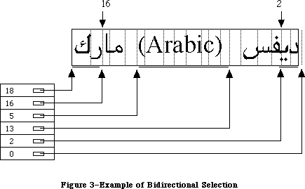 Figure 3–Example of Bidirectional Selection
HiLiteText returns the specific regions to be highlighted in this case as an offset table.
_______________________________________________________________________________
»DrawJust
PROCEDURE DrawJust (textPtr: Ptr; textLength, slop: Integer);
DrawJust is similar to the QuickDraw DrawText routine. It draws the given text at the current pen location in the current font, style, and size. The slop parameter indicates how many extra pixels are to be added to the width of the string when it is drawn. This is useful for justifying text.
_______________________________________________________________________________
»MeasureJust
PROCEDURE MeasureJust (textPtr: Ptr; textLength, slop: Integer; charLocs: Ptr);
MeasureJust is similar to the QuickDraw MeasureText routine. The charLocs parameter should point to an array of textLength+1 integers; MeasureJust will fill it with the TextWidths of the first textLength characters of the text pointed to by textPtr. The first entry in the array will return the width of zero characters, the second the width of the first character, the third the width of the first and second characters, and so forth.
_______________________________________________________________________________
»Transliterate
FUNCTION Transliterate (srcHandle, dstHandle: Handle; target: Integer;
srcMask: Longint): Integer;
Transliterate converts the given text to the closest possible approximation in a different script or type of character. It is the caller’s responsibility to provide storage and dispose of it. The srcMask indicates which character types
(scripts) in the source are to be converted. For example, Japanese text may contain Roman, hiragana, katakana, and kanji characters. The source mask could be used to limit transliteration to hiragana characters only.
The target value specifies what the text is to be transliterated into. The low byte of the target is the format to convert to. A value of –1 means the system script. The high byte contains modifiers, which depend on the specific script number. The following predefined constants are available to help you specify target values:
Constant Value Meaning
smTransAscii 0 Target is Roman script
smTransNative 1 Target is non-Roman script
smTransCase 2 Switch case for any target
smTransLower 16384 Target becomes lowercase
smTransUpper 32768 Target becomes uppercase
smMaskAscii 1 Convert only Roman script
smMaskNative 2 Convert only non-Roman script
smMaskAll –1 Convert all text
The result is 0 for noErr or –1 for transliteration not available.
Transliteration is performed on a “best effort” basis: typically it will be designed to give a unique transliteration into the non-Roman script. This may not be the most phonetic or natural transcription, since those transcriptions are usually ambiguous (for example, in certain transcriptions “th” may refer to the sound in the, the sound in thick, or the sounds in boathouse).
On Roman systems, this routine is typically used to change case. For example, to convert all the characters in a block of text to single-byte Roman
(uppercase), the value of srcMask would be smMaskAll, and target would be smTransUpper+smTransAscii. Each of the Script Interface Systems defines additional target constants to be used during transliteration.
Here are some examples of the effects of transliteration:
to uppercase -----> TO UPPERCASE
TO LOWERCASE -----> to lowercase
_______________________________________________________________________________
»GetScript
FUNCTION GetScript (script, verb: Integer) : LongInt;
X-Ref: Technical Note #243
GetScript is used to retrieve the values of the local script variables and routine vectors. The following predefined constants are available for the verb parameter:
Constant Value Meaning
smScriptVersion 0 Software version
smScriptMunged 2 Script entry changed count
smScriptEnabled 4 Script enabled flag
smScriptRight 6 Right-to-left flag
smScriptJust 8 Justification flag
smScriptRedraw 10 Word redraw flag
smScriptSysFond 12 Preferred system font
smScriptAppFond 14 Preferred application font
smScriptNumber 16 Script 'itl0' ID, from dictionary
smScriptDate 18 Script 'itl1' ID, from dictionary
smScriptSort 20 Script 'itl2' ID, from dictionary
smScriptFlags 22 Script Flags Word
smScriptToken 24 'itl4' ID number
smScriptRsvd 26 Reserved
smScriptLang 28 Script’s language code
smScriptNumDate 30 Number/Date Representation codes
smScriptKeys 32 Script 'KCHR' ID, from dictionary
smScriptIcon 34 Script 'SICN' ID, from dictionary
smScriptPrint 36 Script printer action routine
smScriptTrap 38 Trap entry pointer
smScriptCreator 40 Script file creator
smScriptFile 42 Script file name
smScriptName 44 Script name
Verb values unique to a script are defined by the applicable Script Interface System. GetScript returns 0 if the verb value is not recognized or if the specified script is not installed.
_______________________________________________________________________________
»SetScript
FUNCTION SetScript (script, verb: Integer; param: LongInt) : OSErr;
SetScript is the opposite of GetScript. It is used to change the local script variables and routine vectors and uses the same verb values as GetScript. The value smVerbNotFound is returned if the verb value is not recognized or the script specified is not installed. Otherwise, the function result will be noErr. It is a good idea to first retrieve the original value of the global variable that you want to change, using GetScript. The original value can then be restored with a second call to SetScript as soon as possible.
_______________________________________________________________________________
»GetEnvirons
FUNCTION GetEnvirons (verb: Integer) : LongInt;
X-Ref: Technical Note #243
GetEnvirons is used to retrieve the values of the global Script Manager variables and routine vectors. The following predefined constants are available for the verb argument:
Constant Value Meaning
smVersion 0 Environment version
smMunged 2 Globals changed count
smEnabled 4 Environment enabled flag
smBiDirect 6 Set if scripts of different directions
are installed together
smFontForce 8 Force font flag
smIntlForce 10 Force international utilities flag
smForced 12 Current script forced to system script
smDefault 14 Current script defaulted to Roman script
smPrint 16 Printer action routine
smSysScript 18 System script
smLastScript 20 Last keyboard script
smKeyScript 22 Keyboard script
smSysRef 24 System folder reference number
smKeyCache 26 Keyboard table cache pointer
smKeySwap 28 Swapping table pointer
smGenFlags 30 General Flags
smOverride 32 Script Override flags
smCharPortion 34 Ch vs Sp Extra proportion, 4.12 fixed
This routine returns 0 if the verb is not recognized.
_______________________________________________________________________________
»SetEnvirons
FUNCTION SetEnvirons (verb: Integer; param: LongInt) : OSErr;
SetEnvirons is the opposite of GetEnvirons. It is used to change the global Script Interface System variables and routine vectors; it uses the same verbs as GetEnvirons. The value smVerbNotFound is returned if the verb is not recognized. Otherwise, the function result will be noErr.
It is a good idea to first retrieve the original value of the global variable that you want to change, using GetEnvirons. The original value can then be restored with a second call to SetEnvirons as soon as possible.
_______________________________________________________________________________
»FontScript
FUNCTION FontScript: Integer;
FontScript returns the script code for the font script. The font script is determined by the font of the current grafPort.
_______________________________________________________________________________
»IntlScript
FUNCTION IntlScript: Integer;
IntlScript returns the script code for the International Utilities script. Like the font script, the International Utilities script is determined by the font of the current grafPort. If the Script Manager global IntlForce is off, then IntlScript is the same as the font script; if IntlForce is on, IntlScript is the system script. For further information, see the International Utilities Package chapter in this volume.
_______________________________________________________________________________
»KeyScript
PROCEDURE KeyScript(scriptCode: Integer);
KeyScript is used to set the keyboard script. This routine also changes the keyboard layout to that of the new keyboard script and draws the script icon for the new keyboard script in the upper-right corner of the menu bar.
Warning: Applications can also change the keyboard script without changing
the keyboard layout or the script icon in the menu bar, by calling
the SetEnvirons routine with the smKeyScript verb. However, this
method should only be used to momentarily change the keyboard script
to perform a special operation. Changing the keyboard script without
changing the keyboard layout violates the user interface paradigm and
will cause problems for other Script Manager routines.
_______________________________________________________________________________
»Font2Script
FUNCTION Font2Script(fontNumber: Integer): Integer;
Font2Script translates a font identification number into a script code. This routine is useful for determining to which script a particular font belongs and which fonts are usable under a particular script.
_______________________________________________________________________________
»GetDefFontSize
FUNCTION GetDefFontSize: Integer;
GetDefFontSize fetches the size of the current default font. This routine is in the Pascal interface, not in ROM; it cannot be used with the 64K ROM.
_______________________________________________________________________________
»GetSysFont
FUNCTION GetSysFont: Integer;
GetSysFont fetches the identification number of the current system font. This routine is in the Pascal interface, not in ROM; it cannot be used with the 64K ROM.
_______________________________________________________________________________
»GetAppFont
FUNCTION GetAppFont: Integer;
GetAppFont fetches the identification number of the current application font. This routine is in the Pascal interface, not in ROM.
_______________________________________________________________________________
»GetMBarHeight
FUNCTION GetMBarHeight: Integer;
GetMBarHeight fetches the height of the menu bar as required to hold menu titles in its current font. This routine is in the Pascal interface, not in ROM; it cannot be used with the 64K ROM.
_______________________________________________________________________________
»GetSysJust
FUNCTION GetSysJust: Integer;
GetSysJust returns the value of a global variable that represents the direction in which lines written in the system script are justified: 0 for left justification (the default case) or –1 for right justification. This routine is in the Pascal interface, not in ROM; it cannot be used with the 64K ROM.
_______________________________________________________________________________
»SetSysJust
PROCEDURE SetSysJust (newJust: Integer);
GetSysJust sets a global variable that represents the direction in which lines written in the system script are justified: 0 for left justification (the default case) or –1 for right justification. This routine is in the Pascal interface, not in ROM; it cannot be used with the 64K ROM.
_______________________________________________________________________________
»SCRIPT MANAGER 2.0 ROUTINES
_______________________________________________________________________________
The new text routines include: lexically interpreting different scripts (e.g., in macro languages); allotting justification to different format runs within a line; ordering format runs properly with bidirectional text (Hebrew & Arabic); quickly separating Roman from non-Roman text, and determining word-wrap in text processing. The international utilities text comparison routines were significantly improved in performance, in amounts ranging from 25% to 94%.
_______________________________________________________________________________
»ParseTable
In Pascal:
Type
CharByteTable = Packed Array [0..255] of SignedByte;
Function ParseTable(table: CharByteTable): Boolean;
typedef char CharByteTable[256];
In C:
pascal Boolean ParseTable(CharByteTable table);
Double-byte characters have distinctive high (first) bytes, which allows them to be distinguished from single-byte characters. The ParseTable routine can be used to traverse double-byte text quickly. It does this by filling a table of bytes with values which indicate the extra number of bytes taken by a given character. This array can then be used instead of making function calls on each byte. As with the other script-specific routine calls, the values in the table will vary with the script of the current font in thePort, so you must make sure to set the font correctly.
An entry in the table is set to 0 for a single-byte character and 1 for the first byte of a double-byte character. (With a single-byte script, the entries are all zero.) The return value from the routine will always be true. This routine has always been present in the Script Manager, but was not documented until now. Also note that script systems will never require more than two bytes per character, so you can safely assume that there are only single-byte and double-byte characters.
For example, in the following code the reference to tablePtr[myChar] is functionally equivalent to a use of _CharByte, but does not involve a trap call.
In Pascal:
Var
myChar: Integer;
i, max: Integer;
tablePtr: CharByteTable;
s: String [255];
ParseResult: Boolean;
Begin
ParseResult := ParseTable(tablePtr);
i := 1;
max := length (s);
While i <= max do Begin
myChar := ord(s[i]); {get byte}
i := i + 1; {skip to start of next}
if (tablePtr[myChar] <> 0) then Begin {if double-byte}
myChar := myChar * $100 + ord(s[i]); {include next byte}
i := i + 1; {skip to start of next}
End;
{do something with myChar}
End;
End;
In C:
short mychar;
CharByteTable table;
char *s = "Test String";
Boolean ParseResult;
{
ParseResult = ParseTable(table);
while ( *s ) {
mychar = *s++;
if ( table[mychar] <> 0 )
mychar = mychar << 8) + *s++;
/* do something with mychar */
}
}
Remember that the CharByteTable is specific to the script. There could be two or three scripts installed that are double-byte and have different CharByteTable arrays.
_______________________________________________________________________________
»IntlTokenize
In Pascal:
Function IntlTokenize ( tokenParam : TokenBlockPtr ): TokenResults;
In C:
pascal TokenResults IntlTokenize(TokenBlockPtr tokenParam);
The IntlTokenize routine is intended for use in macro expressions and similar programming constructs intended for general users. It allows the program to recognize variables, symbols and quoted literals without depending on the particular natural language (e.g., English vs. Japanese).
The routine is a mildly programmable regular expression recognizer for parsing text into tokens. The single parameter is a parameter block describing the text to be tokenized, the destination of the token stream, the 'itl4' resource handle, and the various programmable options. IntlTokenize will return a list of tokens found in the text.
In Pascal:
TokenBlock = RECORD
source: Ptr; {pointer to stream of characters}
sourceLength: LongInt; {length of source stream}
tokenList: Ptr; {pointer to array of tokens}
tokenLength: LongInt; {maximum length of TokenList}
tokenCount: LongInt; {number of tokens generated by }
{ tokenizer}
stringList: Ptr; {pointer to stream of identifiers}
stringLength: LongInt; {length of string list}
stringCount: LongInt; {number of bytes currently used}
doString: Boolean; {make strings & put into }
{ StringLIst}
doAppend: Boolean; {append to TokenList rather }
{ than replace}
doAlphanumeric: Boolean; {identifiers may include numeric}
doNest: Boolean; {do comments nest?}
leftDelims, rightDelims: ARRAY[0..1] OF TokenType;
leftComment, rightComment: ARRAY[0..3] OF TokenType;
escapeCode: TokenType; {escape symbol code}
decimalCode: TokenType; {decimal symbol code}
itlResource: Handle; {itl4 resource handle of }
{ current script}
reserved: array [0..7] of Longint; { must be zeroed! }
END;
TokenType = Integer; {see list of TokenType values at end of document}
TokenRec = RECORD
theToken: TokenType;
Position: Ptr; {ptr into original source}
length: LongInt; {length of text in original source}
stringPosition: StringPtr; {Pascal/C string copy of identifier}
END;
In C:
struct TokenBlock {
Ptr source; /*pointer to stream of characters*/
long sourceLength; /*length of source stream*/
Ptr tokenList; /*pointer to array of tokens*/
long tokenLength; /*maximum length of TokenList*/
long tokenCount; /*number tokens generated by tokenizer*/
Ptr stringList; /*pointer to stream of identifiers*/
long stringLength; /*length of string list*/
long stringCount; /*number of bytes currently used*/
Boolean doString; /*make strings & put into StringLIst*/
Boolean doAppend; /*append to TokenList rather than replace*/
Boolean doAlphanumeric; /*identifiers may include numeric*/
Boolean doNest; /*do comments nest?*/
TokenType leftDelims[2];
TokenType rightDelims[2];
TokenType leftComment[4];
TokenType rightComment[4];
TokenType escapeCode; /*escape symbol code*/
TokenType decimalCode;
Handle itlResource; /*ptr to itl4 resource of current script*/
long reserved[8]; /*must be zero!*/
};
#ifndef __cplusplus
typedef struct TokenBlock TokenBlock;
#endif
typedef TokenBlock *TokenBlockPtr;
typedef short TokenType;
struct TokenRec {
TokenType theToken;
Ptr Position; /*pointer into original Source*/
long length; /*length of text in original source*/
StringPtr stringPosition; /*Pascal/C string copy of identifier*/
};
For the TokenBlock record:
source is a pointer to the beginning of a stream of characters
(not a Pascal string).
sourceLength is the number of characters in the source stream.
tokenList is a pointer to memory allocated by the application for the
token stream. The tokenizer places the tokens it generates
at and after the address in tokenList.
tokenLength is the number of tokens that will fit in the memory pointed
to by tokenList (not the number of bytes).
tokenCount is the number of tokens that are currently occupying the space
pointed to by tokenList. If the doAppend flag is true, then
tokenCount must be a correct number before calling the
tokenizer. The tokenizer modifies this value to show how many
tokens are in the token stream after tokenizing.
stringList is a pointer to memory allocated by the application for strings
that the tokenizer generates if the doString flag is true. If
the flag is false, then stringList is ignored.
stringLength is the number of bytes of memory allocated for stringList.
stringCount is the number of bytes that are currently occupying the space
pointed to by stringList. If the doAppend flag is true, then
stringCount must be a correct number before calling the
tokenizer. The tokenizer modifies this value to show how many
bytes are in the string stream after tokenizing.
doString is a boolean flag that instructs the tokenizer to create a
sequence of even-boundaried, null-terminated Pascal strings.
Each token generated by the tokenizer will have a string
created to represent it if the flag is true. Each token
record contains the address of the string that represents it.
doAppend is a boolean flag that instructs the tokenizer to append tokens
to the space pointed to by tokenList rather than replace
whatever is there. tokenCount must correctly reflect the
number of tokens in the space pointed to by tokenList.
doAlphanumeric is a boolean flag that, when true, states that numerics may
be mixed with alphabetics to create alphabetic tokens.
doNest is a boolean flag that instructs the tokenizer to allow nested
comments of any depth.
leftDelims is an array of two integers, each of which corresponds to the
class of the symbol that may be used as a left delimiter for a
quoted literal. Double quotes, for instance, is class
token2Quote. If only one left delimiter is needed, the other
must be specified to be delimPad.
rightDelims is an array of two integers, each of which corresponds to the
class of the symbol that may be used as the matching right
delimiter for the corresponding left delimiter in leftDelims.
leftComment is an array of four integers. Each successive pair of two
describes a pair of tokens that may be used as left delimiters
for comments. These tokens are stored in reverse order. The
tokens numbered zero and two are the second tokens of the two-
token sequences; the tokens numbered one and three are the
first tokens of the two-token sequences.
If only one token is needed for a delimiter, the second token
must be specified to be delimPad. If only one delimiter is
needed, then both of the tokens allocated for the other symbol
must be delimPad. The first token of a two-token sequence is
the higher position in the array. For example, the two left
delimiters (* and { would be specified as
leftComment[0]:= tokenAsterisk; (*asterisk*)
leftComment[1]:= tokenLeftParen; (*left parenthesis*)
leftComment[2]:= delimPad ; (*nothing*)
leftComment[3]:= tokenLeftCurly; (*curly brace*)
rightComment is an array of four integers with similar characteristics as
leftComment. The positions in the array of the right
delimiters must be the same as their matching left delimiters.
escapeChar is a single integer that is the class of the symbol that may be
used for an escape character. The tokenizer considers the
escape character to be an escape character (as opposed to being
itself) only within quoted literals.
If backslash (\) is given as the escapeChar, then the tokenizer
would consider it an escape character in the following string:
"This is an escape\n"
It would not be considered an escape character in a non-quoted
string like the following:
This isn't an escape\n
decimalCode is a single integer that is the tokenType that may be used for
a decimal point. The tokenizer considers the decimal character
to be a decimal character (as opposed to being itself) only
when flanked by numeric or alternate numeric characters, or
when following them. When the strings option is selected, the
decimal character will always be transliterated to an ASCII
period (and alternate numbers will be transliterated to ASCII
digits).
itlResource is a handle to the 'itl4' resource of the script in current
use. The application must load the 'itl4' resource and place
its handle here before calling the tokenizer. Every time the
script of the text to be tokenized changes, the pointer to the
respective 'itl4' resource must be placed here.
reserved locations must all be zeroed.
For the token record:
theToken is the ordinal value of the token represented by the token
record.
position points to the first character in the original text that
caused this particular token to be generated.
length is the length in bytes of the original text corresponding
to this token.
stringPosition points to a null-terminated, even-boundariedPascal string
that is the result of using the doString option. If doString
is false then stringPosition is always set to NIL.
The available token types are: whitespace, newline, alphabetic, numeric, decimal, endOfStream, unknown, alternate numeric, alternate decimal, and a host of fixed token symbols, such as ( # @ : := .
The tokenizer does not attempt to provide complete lexical analysis, but rather offers a programmable “pre-lex” function whose output should then be processed by the application at a lexical or syntactic level.
The programmable options include: whether to generate strings which correspond to the text of each token; whether the current tokenize call is to append to, rather than replace, the current token list; whether alphabetic tokens may have numerics within them; whether comments may be nested; what the left and right delimiters for comments are (up to two sets may be specified); what the left and right delimiters for quoted literals are (up to two sets may be specified); what the escape character is; and what the decimal point symbol is.
Some users may use two or more different scripts within a program. However, each script’s character stream must be passed separately to the tokenizer because different resources must be passed to the tokenizer depending on the script of the text stream. Appending tokens to the token stream lets the application see the tokens generated by the different scripts’ characters as a single token stream. Restriction: users may not change scripts within a comment or quoted literal because these syntactic units must be complete within a single call to the tokenizer in order to avoid tokenizer syntax errors.
The application may specify up to two pairs of delimiters each for both quoted literals and comments. Quoted literal delimiters consist of a single symbol, and comment delimiters may be either one or two symbols (including newline for notations whose comments automatically terminate at the end of lines). The characters that compose literals within quoted literals and comments are normally defined to have no syntactic significance; however, the escape character within a quoted literal does signal that the following character should not be treated as the right delimiter. Each delimiter is represented by a token, as is the literal between left and right delimiters.
If two different comment delimiters are specified by the application, then the doNest flag always applies to both. Comments may be nested if so specified by the doNest flag with one restriction that must be strictly observed in order to prevent the tokenizer from malfunctioning: nesting is legal only if both the left and right delimiters for the comment token are composed of two symbols each. In this version, there is limited support for nested comments. When using this feature, test to insure that it meets your requirements.
An escape character between left and right delimiters of a quoted literal signals that the following character is not the right delimiter. An escape character is not specially recognized and has no significance outside of quoted literals. When an escape character is encountered, the portion of the literal before the escape is placed into a single token, the escape character itself becomes a token, the character following the escape becomes a token, and the portion of the literal following the escape sequence becomes a token.
A sequence of whitespace characters becomes a single token.
Newline, or carriage return, becomes a single token.
A sequence of alphabetic characters becomes an alphabetic token. If the doAlphanumeric flag is set, then alphabetic characters include digits, but the first character must be alphabetic.
A sequence of numeric characters becomes a numeric token.
A sequence of numeric characters followed by a decimal mark, and optionally followed by more numeric characters, becomes a realNumber token.
Some scripts have not only “English” digits, but also their own numeral codes, which of course will be unrecognizable to the typical application. A sequence of alternate digits becomes an alternate numeric token. If the strings option is selected then the digits will be transliterated to “English” digits. This includes the realNumber tokens, whose results become alternate real tokens.
The end of the character stream becomes a token.
A token record consists of a token code, a pointer into the source stream
(signifying the first character of the sequence that generated the token), the byte length of the sequence of characters that generated the token, and space for a pointer to a Pascal string, explained next.
The application may instruct the tokenizer to generate null-terminated, even-boundaried Pascal strings corresponding to each token. In this case, if the token is anything but alphabetic or numeric then the text of the source stream is copied verbatim into the Pascal string. Otherwise, if the text in the source stream is Roman letters or numbers then those characters are transliterated into Macintosh eight-bit ASCII and a string is created from
the result, allowing users of other languages to transparently use their own script’s numerals or Roman characters for numbers or keywords. Non-Roman alphabetics are copied verbatim.
Semantic attributes of byte codes vary from natural language to natural language. As an example, in the Macintosh character set code $81 is an Å, but in Kanji this code is the first byte of many double-byte characters, some of which are alphabetic, some numeric, and some symbols. This information is retrieved from the 'itl4' resource, which also contains a canonical string format for the fixed tokens, so that the internal format of formulæ can be redisplayed in the original language.
'itl4' also holds a string copy routine which converts the native text to the corresponding English (except for alphanumerics). As with the other international resources, the choice of 'itl4' depends on the script interface system in use.
Figure 3–Example of Bidirectional Selection
HiLiteText returns the specific regions to be highlighted in this case as an offset table.
_______________________________________________________________________________
»DrawJust
PROCEDURE DrawJust (textPtr: Ptr; textLength, slop: Integer);
DrawJust is similar to the QuickDraw DrawText routine. It draws the given text at the current pen location in the current font, style, and size. The slop parameter indicates how many extra pixels are to be added to the width of the string when it is drawn. This is useful for justifying text.
_______________________________________________________________________________
»MeasureJust
PROCEDURE MeasureJust (textPtr: Ptr; textLength, slop: Integer; charLocs: Ptr);
MeasureJust is similar to the QuickDraw MeasureText routine. The charLocs parameter should point to an array of textLength+1 integers; MeasureJust will fill it with the TextWidths of the first textLength characters of the text pointed to by textPtr. The first entry in the array will return the width of zero characters, the second the width of the first character, the third the width of the first and second characters, and so forth.
_______________________________________________________________________________
»Transliterate
FUNCTION Transliterate (srcHandle, dstHandle: Handle; target: Integer;
srcMask: Longint): Integer;
Transliterate converts the given text to the closest possible approximation in a different script or type of character. It is the caller’s responsibility to provide storage and dispose of it. The srcMask indicates which character types
(scripts) in the source are to be converted. For example, Japanese text may contain Roman, hiragana, katakana, and kanji characters. The source mask could be used to limit transliteration to hiragana characters only.
The target value specifies what the text is to be transliterated into. The low byte of the target is the format to convert to. A value of –1 means the system script. The high byte contains modifiers, which depend on the specific script number. The following predefined constants are available to help you specify target values:
Constant Value Meaning
smTransAscii 0 Target is Roman script
smTransNative 1 Target is non-Roman script
smTransCase 2 Switch case for any target
smTransLower 16384 Target becomes lowercase
smTransUpper 32768 Target becomes uppercase
smMaskAscii 1 Convert only Roman script
smMaskNative 2 Convert only non-Roman script
smMaskAll –1 Convert all text
The result is 0 for noErr or –1 for transliteration not available.
Transliteration is performed on a “best effort” basis: typically it will be designed to give a unique transliteration into the non-Roman script. This may not be the most phonetic or natural transcription, since those transcriptions are usually ambiguous (for example, in certain transcriptions “th” may refer to the sound in the, the sound in thick, or the sounds in boathouse).
On Roman systems, this routine is typically used to change case. For example, to convert all the characters in a block of text to single-byte Roman
(uppercase), the value of srcMask would be smMaskAll, and target would be smTransUpper+smTransAscii. Each of the Script Interface Systems defines additional target constants to be used during transliteration.
Here are some examples of the effects of transliteration:
to uppercase -----> TO UPPERCASE
TO LOWERCASE -----> to lowercase
_______________________________________________________________________________
»GetScript
FUNCTION GetScript (script, verb: Integer) : LongInt;
X-Ref: Technical Note #243
GetScript is used to retrieve the values of the local script variables and routine vectors. The following predefined constants are available for the verb parameter:
Constant Value Meaning
smScriptVersion 0 Software version
smScriptMunged 2 Script entry changed count
smScriptEnabled 4 Script enabled flag
smScriptRight 6 Right-to-left flag
smScriptJust 8 Justification flag
smScriptRedraw 10 Word redraw flag
smScriptSysFond 12 Preferred system font
smScriptAppFond 14 Preferred application font
smScriptNumber 16 Script 'itl0' ID, from dictionary
smScriptDate 18 Script 'itl1' ID, from dictionary
smScriptSort 20 Script 'itl2' ID, from dictionary
smScriptFlags 22 Script Flags Word
smScriptToken 24 'itl4' ID number
smScriptRsvd 26 Reserved
smScriptLang 28 Script’s language code
smScriptNumDate 30 Number/Date Representation codes
smScriptKeys 32 Script 'KCHR' ID, from dictionary
smScriptIcon 34 Script 'SICN' ID, from dictionary
smScriptPrint 36 Script printer action routine
smScriptTrap 38 Trap entry pointer
smScriptCreator 40 Script file creator
smScriptFile 42 Script file name
smScriptName 44 Script name
Verb values unique to a script are defined by the applicable Script Interface System. GetScript returns 0 if the verb value is not recognized or if the specified script is not installed.
_______________________________________________________________________________
»SetScript
FUNCTION SetScript (script, verb: Integer; param: LongInt) : OSErr;
SetScript is the opposite of GetScript. It is used to change the local script variables and routine vectors and uses the same verb values as GetScript. The value smVerbNotFound is returned if the verb value is not recognized or the script specified is not installed. Otherwise, the function result will be noErr. It is a good idea to first retrieve the original value of the global variable that you want to change, using GetScript. The original value can then be restored with a second call to SetScript as soon as possible.
_______________________________________________________________________________
»GetEnvirons
FUNCTION GetEnvirons (verb: Integer) : LongInt;
X-Ref: Technical Note #243
GetEnvirons is used to retrieve the values of the global Script Manager variables and routine vectors. The following predefined constants are available for the verb argument:
Constant Value Meaning
smVersion 0 Environment version
smMunged 2 Globals changed count
smEnabled 4 Environment enabled flag
smBiDirect 6 Set if scripts of different directions
are installed together
smFontForce 8 Force font flag
smIntlForce 10 Force international utilities flag
smForced 12 Current script forced to system script
smDefault 14 Current script defaulted to Roman script
smPrint 16 Printer action routine
smSysScript 18 System script
smLastScript 20 Last keyboard script
smKeyScript 22 Keyboard script
smSysRef 24 System folder reference number
smKeyCache 26 Keyboard table cache pointer
smKeySwap 28 Swapping table pointer
smGenFlags 30 General Flags
smOverride 32 Script Override flags
smCharPortion 34 Ch vs Sp Extra proportion, 4.12 fixed
This routine returns 0 if the verb is not recognized.
_______________________________________________________________________________
»SetEnvirons
FUNCTION SetEnvirons (verb: Integer; param: LongInt) : OSErr;
SetEnvirons is the opposite of GetEnvirons. It is used to change the global Script Interface System variables and routine vectors; it uses the same verbs as GetEnvirons. The value smVerbNotFound is returned if the verb is not recognized. Otherwise, the function result will be noErr.
It is a good idea to first retrieve the original value of the global variable that you want to change, using GetEnvirons. The original value can then be restored with a second call to SetEnvirons as soon as possible.
_______________________________________________________________________________
»FontScript
FUNCTION FontScript: Integer;
FontScript returns the script code for the font script. The font script is determined by the font of the current grafPort.
_______________________________________________________________________________
»IntlScript
FUNCTION IntlScript: Integer;
IntlScript returns the script code for the International Utilities script. Like the font script, the International Utilities script is determined by the font of the current grafPort. If the Script Manager global IntlForce is off, then IntlScript is the same as the font script; if IntlForce is on, IntlScript is the system script. For further information, see the International Utilities Package chapter in this volume.
_______________________________________________________________________________
»KeyScript
PROCEDURE KeyScript(scriptCode: Integer);
KeyScript is used to set the keyboard script. This routine also changes the keyboard layout to that of the new keyboard script and draws the script icon for the new keyboard script in the upper-right corner of the menu bar.
Warning: Applications can also change the keyboard script without changing
the keyboard layout or the script icon in the menu bar, by calling
the SetEnvirons routine with the smKeyScript verb. However, this
method should only be used to momentarily change the keyboard script
to perform a special operation. Changing the keyboard script without
changing the keyboard layout violates the user interface paradigm and
will cause problems for other Script Manager routines.
_______________________________________________________________________________
»Font2Script
FUNCTION Font2Script(fontNumber: Integer): Integer;
Font2Script translates a font identification number into a script code. This routine is useful for determining to which script a particular font belongs and which fonts are usable under a particular script.
_______________________________________________________________________________
»GetDefFontSize
FUNCTION GetDefFontSize: Integer;
GetDefFontSize fetches the size of the current default font. This routine is in the Pascal interface, not in ROM; it cannot be used with the 64K ROM.
_______________________________________________________________________________
»GetSysFont
FUNCTION GetSysFont: Integer;
GetSysFont fetches the identification number of the current system font. This routine is in the Pascal interface, not in ROM; it cannot be used with the 64K ROM.
_______________________________________________________________________________
»GetAppFont
FUNCTION GetAppFont: Integer;
GetAppFont fetches the identification number of the current application font. This routine is in the Pascal interface, not in ROM.
_______________________________________________________________________________
»GetMBarHeight
FUNCTION GetMBarHeight: Integer;
GetMBarHeight fetches the height of the menu bar as required to hold menu titles in its current font. This routine is in the Pascal interface, not in ROM; it cannot be used with the 64K ROM.
_______________________________________________________________________________
»GetSysJust
FUNCTION GetSysJust: Integer;
GetSysJust returns the value of a global variable that represents the direction in which lines written in the system script are justified: 0 for left justification (the default case) or –1 for right justification. This routine is in the Pascal interface, not in ROM; it cannot be used with the 64K ROM.
_______________________________________________________________________________
»SetSysJust
PROCEDURE SetSysJust (newJust: Integer);
GetSysJust sets a global variable that represents the direction in which lines written in the system script are justified: 0 for left justification (the default case) or –1 for right justification. This routine is in the Pascal interface, not in ROM; it cannot be used with the 64K ROM.
_______________________________________________________________________________
»SCRIPT MANAGER 2.0 ROUTINES
_______________________________________________________________________________
The new text routines include: lexically interpreting different scripts (e.g., in macro languages); allotting justification to different format runs within a line; ordering format runs properly with bidirectional text (Hebrew & Arabic); quickly separating Roman from non-Roman text, and determining word-wrap in text processing. The international utilities text comparison routines were significantly improved in performance, in amounts ranging from 25% to 94%.
_______________________________________________________________________________
»ParseTable
In Pascal:
Type
CharByteTable = Packed Array [0..255] of SignedByte;
Function ParseTable(table: CharByteTable): Boolean;
typedef char CharByteTable[256];
In C:
pascal Boolean ParseTable(CharByteTable table);
Double-byte characters have distinctive high (first) bytes, which allows them to be distinguished from single-byte characters. The ParseTable routine can be used to traverse double-byte text quickly. It does this by filling a table of bytes with values which indicate the extra number of bytes taken by a given character. This array can then be used instead of making function calls on each byte. As with the other script-specific routine calls, the values in the table will vary with the script of the current font in thePort, so you must make sure to set the font correctly.
An entry in the table is set to 0 for a single-byte character and 1 for the first byte of a double-byte character. (With a single-byte script, the entries are all zero.) The return value from the routine will always be true. This routine has always been present in the Script Manager, but was not documented until now. Also note that script systems will never require more than two bytes per character, so you can safely assume that there are only single-byte and double-byte characters.
For example, in the following code the reference to tablePtr[myChar] is functionally equivalent to a use of _CharByte, but does not involve a trap call.
In Pascal:
Var
myChar: Integer;
i, max: Integer;
tablePtr: CharByteTable;
s: String [255];
ParseResult: Boolean;
Begin
ParseResult := ParseTable(tablePtr);
i := 1;
max := length (s);
While i <= max do Begin
myChar := ord(s[i]); {get byte}
i := i + 1; {skip to start of next}
if (tablePtr[myChar] <> 0) then Begin {if double-byte}
myChar := myChar * $100 + ord(s[i]); {include next byte}
i := i + 1; {skip to start of next}
End;
{do something with myChar}
End;
End;
In C:
short mychar;
CharByteTable table;
char *s = "Test String";
Boolean ParseResult;
{
ParseResult = ParseTable(table);
while ( *s ) {
mychar = *s++;
if ( table[mychar] <> 0 )
mychar = mychar << 8) + *s++;
/* do something with mychar */
}
}
Remember that the CharByteTable is specific to the script. There could be two or three scripts installed that are double-byte and have different CharByteTable arrays.
_______________________________________________________________________________
»IntlTokenize
In Pascal:
Function IntlTokenize ( tokenParam : TokenBlockPtr ): TokenResults;
In C:
pascal TokenResults IntlTokenize(TokenBlockPtr tokenParam);
The IntlTokenize routine is intended for use in macro expressions and similar programming constructs intended for general users. It allows the program to recognize variables, symbols and quoted literals without depending on the particular natural language (e.g., English vs. Japanese).
The routine is a mildly programmable regular expression recognizer for parsing text into tokens. The single parameter is a parameter block describing the text to be tokenized, the destination of the token stream, the 'itl4' resource handle, and the various programmable options. IntlTokenize will return a list of tokens found in the text.
In Pascal:
TokenBlock = RECORD
source: Ptr; {pointer to stream of characters}
sourceLength: LongInt; {length of source stream}
tokenList: Ptr; {pointer to array of tokens}
tokenLength: LongInt; {maximum length of TokenList}
tokenCount: LongInt; {number of tokens generated by }
{ tokenizer}
stringList: Ptr; {pointer to stream of identifiers}
stringLength: LongInt; {length of string list}
stringCount: LongInt; {number of bytes currently used}
doString: Boolean; {make strings & put into }
{ StringLIst}
doAppend: Boolean; {append to TokenList rather }
{ than replace}
doAlphanumeric: Boolean; {identifiers may include numeric}
doNest: Boolean; {do comments nest?}
leftDelims, rightDelims: ARRAY[0..1] OF TokenType;
leftComment, rightComment: ARRAY[0..3] OF TokenType;
escapeCode: TokenType; {escape symbol code}
decimalCode: TokenType; {decimal symbol code}
itlResource: Handle; {itl4 resource handle of }
{ current script}
reserved: array [0..7] of Longint; { must be zeroed! }
END;
TokenType = Integer; {see list of TokenType values at end of document}
TokenRec = RECORD
theToken: TokenType;
Position: Ptr; {ptr into original source}
length: LongInt; {length of text in original source}
stringPosition: StringPtr; {Pascal/C string copy of identifier}
END;
In C:
struct TokenBlock {
Ptr source; /*pointer to stream of characters*/
long sourceLength; /*length of source stream*/
Ptr tokenList; /*pointer to array of tokens*/
long tokenLength; /*maximum length of TokenList*/
long tokenCount; /*number tokens generated by tokenizer*/
Ptr stringList; /*pointer to stream of identifiers*/
long stringLength; /*length of string list*/
long stringCount; /*number of bytes currently used*/
Boolean doString; /*make strings & put into StringLIst*/
Boolean doAppend; /*append to TokenList rather than replace*/
Boolean doAlphanumeric; /*identifiers may include numeric*/
Boolean doNest; /*do comments nest?*/
TokenType leftDelims[2];
TokenType rightDelims[2];
TokenType leftComment[4];
TokenType rightComment[4];
TokenType escapeCode; /*escape symbol code*/
TokenType decimalCode;
Handle itlResource; /*ptr to itl4 resource of current script*/
long reserved[8]; /*must be zero!*/
};
#ifndef __cplusplus
typedef struct TokenBlock TokenBlock;
#endif
typedef TokenBlock *TokenBlockPtr;
typedef short TokenType;
struct TokenRec {
TokenType theToken;
Ptr Position; /*pointer into original Source*/
long length; /*length of text in original source*/
StringPtr stringPosition; /*Pascal/C string copy of identifier*/
};
For the TokenBlock record:
source is a pointer to the beginning of a stream of characters
(not a Pascal string).
sourceLength is the number of characters in the source stream.
tokenList is a pointer to memory allocated by the application for the
token stream. The tokenizer places the tokens it generates
at and after the address in tokenList.
tokenLength is the number of tokens that will fit in the memory pointed
to by tokenList (not the number of bytes).
tokenCount is the number of tokens that are currently occupying the space
pointed to by tokenList. If the doAppend flag is true, then
tokenCount must be a correct number before calling the
tokenizer. The tokenizer modifies this value to show how many
tokens are in the token stream after tokenizing.
stringList is a pointer to memory allocated by the application for strings
that the tokenizer generates if the doString flag is true. If
the flag is false, then stringList is ignored.
stringLength is the number of bytes of memory allocated for stringList.
stringCount is the number of bytes that are currently occupying the space
pointed to by stringList. If the doAppend flag is true, then
stringCount must be a correct number before calling the
tokenizer. The tokenizer modifies this value to show how many
bytes are in the string stream after tokenizing.
doString is a boolean flag that instructs the tokenizer to create a
sequence of even-boundaried, null-terminated Pascal strings.
Each token generated by the tokenizer will have a string
created to represent it if the flag is true. Each token
record contains the address of the string that represents it.
doAppend is a boolean flag that instructs the tokenizer to append tokens
to the space pointed to by tokenList rather than replace
whatever is there. tokenCount must correctly reflect the
number of tokens in the space pointed to by tokenList.
doAlphanumeric is a boolean flag that, when true, states that numerics may
be mixed with alphabetics to create alphabetic tokens.
doNest is a boolean flag that instructs the tokenizer to allow nested
comments of any depth.
leftDelims is an array of two integers, each of which corresponds to the
class of the symbol that may be used as a left delimiter for a
quoted literal. Double quotes, for instance, is class
token2Quote. If only one left delimiter is needed, the other
must be specified to be delimPad.
rightDelims is an array of two integers, each of which corresponds to the
class of the symbol that may be used as the matching right
delimiter for the corresponding left delimiter in leftDelims.
leftComment is an array of four integers. Each successive pair of two
describes a pair of tokens that may be used as left delimiters
for comments. These tokens are stored in reverse order. The
tokens numbered zero and two are the second tokens of the two-
token sequences; the tokens numbered one and three are the
first tokens of the two-token sequences.
If only one token is needed for a delimiter, the second token
must be specified to be delimPad. If only one delimiter is
needed, then both of the tokens allocated for the other symbol
must be delimPad. The first token of a two-token sequence is
the higher position in the array. For example, the two left
delimiters (* and { would be specified as
leftComment[0]:= tokenAsterisk; (*asterisk*)
leftComment[1]:= tokenLeftParen; (*left parenthesis*)
leftComment[2]:= delimPad ; (*nothing*)
leftComment[3]:= tokenLeftCurly; (*curly brace*)
rightComment is an array of four integers with similar characteristics as
leftComment. The positions in the array of the right
delimiters must be the same as their matching left delimiters.
escapeChar is a single integer that is the class of the symbol that may be
used for an escape character. The tokenizer considers the
escape character to be an escape character (as opposed to being
itself) only within quoted literals.
If backslash (\) is given as the escapeChar, then the tokenizer
would consider it an escape character in the following string:
"This is an escape\n"
It would not be considered an escape character in a non-quoted
string like the following:
This isn't an escape\n
decimalCode is a single integer that is the tokenType that may be used for
a decimal point. The tokenizer considers the decimal character
to be a decimal character (as opposed to being itself) only
when flanked by numeric or alternate numeric characters, or
when following them. When the strings option is selected, the
decimal character will always be transliterated to an ASCII
period (and alternate numbers will be transliterated to ASCII
digits).
itlResource is a handle to the 'itl4' resource of the script in current
use. The application must load the 'itl4' resource and place
its handle here before calling the tokenizer. Every time the
script of the text to be tokenized changes, the pointer to the
respective 'itl4' resource must be placed here.
reserved locations must all be zeroed.
For the token record:
theToken is the ordinal value of the token represented by the token
record.
position points to the first character in the original text that
caused this particular token to be generated.
length is the length in bytes of the original text corresponding
to this token.
stringPosition points to a null-terminated, even-boundariedPascal string
that is the result of using the doString option. If doString
is false then stringPosition is always set to NIL.
The available token types are: whitespace, newline, alphabetic, numeric, decimal, endOfStream, unknown, alternate numeric, alternate decimal, and a host of fixed token symbols, such as ( # @ : := .
The tokenizer does not attempt to provide complete lexical analysis, but rather offers a programmable “pre-lex” function whose output should then be processed by the application at a lexical or syntactic level.
The programmable options include: whether to generate strings which correspond to the text of each token; whether the current tokenize call is to append to, rather than replace, the current token list; whether alphabetic tokens may have numerics within them; whether comments may be nested; what the left and right delimiters for comments are (up to two sets may be specified); what the left and right delimiters for quoted literals are (up to two sets may be specified); what the escape character is; and what the decimal point symbol is.
Some users may use two or more different scripts within a program. However, each script’s character stream must be passed separately to the tokenizer because different resources must be passed to the tokenizer depending on the script of the text stream. Appending tokens to the token stream lets the application see the tokens generated by the different scripts’ characters as a single token stream. Restriction: users may not change scripts within a comment or quoted literal because these syntactic units must be complete within a single call to the tokenizer in order to avoid tokenizer syntax errors.
The application may specify up to two pairs of delimiters each for both quoted literals and comments. Quoted literal delimiters consist of a single symbol, and comment delimiters may be either one or two symbols (including newline for notations whose comments automatically terminate at the end of lines). The characters that compose literals within quoted literals and comments are normally defined to have no syntactic significance; however, the escape character within a quoted literal does signal that the following character should not be treated as the right delimiter. Each delimiter is represented by a token, as is the literal between left and right delimiters.
If two different comment delimiters are specified by the application, then the doNest flag always applies to both. Comments may be nested if so specified by the doNest flag with one restriction that must be strictly observed in order to prevent the tokenizer from malfunctioning: nesting is legal only if both the left and right delimiters for the comment token are composed of two symbols each. In this version, there is limited support for nested comments. When using this feature, test to insure that it meets your requirements.
An escape character between left and right delimiters of a quoted literal signals that the following character is not the right delimiter. An escape character is not specially recognized and has no significance outside of quoted literals. When an escape character is encountered, the portion of the literal before the escape is placed into a single token, the escape character itself becomes a token, the character following the escape becomes a token, and the portion of the literal following the escape sequence becomes a token.
A sequence of whitespace characters becomes a single token.
Newline, or carriage return, becomes a single token.
A sequence of alphabetic characters becomes an alphabetic token. If the doAlphanumeric flag is set, then alphabetic characters include digits, but the first character must be alphabetic.
A sequence of numeric characters becomes a numeric token.
A sequence of numeric characters followed by a decimal mark, and optionally followed by more numeric characters, becomes a realNumber token.
Some scripts have not only “English” digits, but also their own numeral codes, which of course will be unrecognizable to the typical application. A sequence of alternate digits becomes an alternate numeric token. If the strings option is selected then the digits will be transliterated to “English” digits. This includes the realNumber tokens, whose results become alternate real tokens.
The end of the character stream becomes a token.
A token record consists of a token code, a pointer into the source stream
(signifying the first character of the sequence that generated the token), the byte length of the sequence of characters that generated the token, and space for a pointer to a Pascal string, explained next.
The application may instruct the tokenizer to generate null-terminated, even-boundaried Pascal strings corresponding to each token. In this case, if the token is anything but alphabetic or numeric then the text of the source stream is copied verbatim into the Pascal string. Otherwise, if the text in the source stream is Roman letters or numbers then those characters are transliterated into Macintosh eight-bit ASCII and a string is created from
the result, allowing users of other languages to transparently use their own script’s numerals or Roman characters for numbers or keywords. Non-Roman alphabetics are copied verbatim.
Semantic attributes of byte codes vary from natural language to natural language. As an example, in the Macintosh character set code $81 is an Å, but in Kanji this code is the first byte of many double-byte characters, some of which are alphabetic, some numeric, and some symbols. This information is retrieved from the 'itl4' resource, which also contains a canonical string format for the fixed tokens, so that the internal format of formulæ can be redisplayed in the original language.
'itl4' also holds a string copy routine which converts the native text to the corresponding English (except for alphanumerics). As with the other international resources, the choice of 'itl4' depends on the script interface system in use.
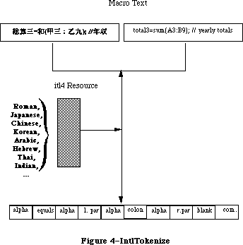 Figure 4–IntlTokenize
The untokenTable in the 'itl4' resource contains standard representations for the fixed tokens, and can be used to display the internal format. An example of how a user might access this table and use the token information follows:
In Pascal:
Type
UntokenTable = Record
len: Integer;
lastToken: Integer;
index: array [0..255] of Integer;
{index table; last = lastToken}
{list of Pascal strings here. index pointers }
{ are from front of table}
End;
UntokenTablePtr = ^UntokenTable;
UntokenTableHandle = ^UntokenTablePtr;
Function GetUntokenTable( Var x: UntokenTableHandle ): Boolean;
Var
itl4: itl4Handle;
P : UntokenTablePtr;
Begin
GetUntokenTable := false; {assume error}
itl4 := itl4Handle(IUGetIntl(4)); {get itl4 record}
if itl4 <> nil then begin {if ok}
HLock(Handle(itl4)); {lock for safety}
P := UntokenTablePtr(ord(itl4^)+itl4^^.untokenOffset);
{untokenize parts subtable}
With P^ Do Begin {using resource table}
x := UntokenTableHandle(NewHandle(len));
{make handle of proper size}
BlockMove(Ptr(p),Ptr(x^),len); {copy contents}
End;
HUnlock(Handle(itl4)); {free back up}
GetUntokenTable := true; {no error}
End;
End;
If (GetUntokenTable(myUntokenTable)) then
With curToken^ Do Case theToken OF
{. . .}
tokenAlpha:
AppendString( myVariable[i] );
Otherwise With myUntokenTable^^, curToken^ Do Begin
If theToken > lastToken Then Begin
AppendString( '?' );
End Else Begin
sPtr := Pointer(ord(@len) + index[theToken]);
AppendString(sPtr^);
End; {if}
End; {item}
End; {case}
In C:
struct UntokenTable {
short len;
short lastToken;
short index[256]; /*index table; last = lastToken*/
};
#ifndef __cplusplus
typedef struct UntokenTable UntokenTable;
#endif
typedef UntokenTable *UntokenTablePtr, **UntokenTableHandle;
GetUntokenTable(UntokenTableHandle *x)
{
Itl4Handle itl4;
UntokenTablePtr p;
itl4 = (Itl4Handle)IUGetIntl(4);
if (itl4) {
HLock((Handle)itl4);
P = (UntokenTablePtr)( (char *)(*itl4) + ( (*itl4)->unTokenOffset ) );
*x = (UntokenTableHandle)NewHandle(p->len);
if (x)
BlockMove((Ptr)p,(Ptr)**x,p->len);
HUnlock((Handle)itl4);
return((short)*x);
}
else
return(0);
}
if ( GetUntokenTable(myUntokenTable) )
switch curtoken->theToken {
/* ... */
case tokenAlpha:
AppendString(myvariable[i]);
break;
default:
if (curtoken->theToken > lastToken)
AppendString("?");
else {
Hlock((Handle)myUntokenTable);
sptr = (char *)(*myUntokenTable) +
(*myUntokenTable)->index[curtoken->theToken];
AppendString(sptr);
HUnlock((Handle)myUntokenTable);
}
break;
}
_______________________________________________________________________________
»PortionText
In Pascal:
Function PortionText (textPtr :Ptr; textLen : Longint): Fixed; {proportion}
In C:
pascal Fixed PortionText(Ptr textPtr,long textLen);
This routine returns a result which indicates the proportion of justification that should be allocated to this text when compared to other text. It is used when justifying a sequence of format runs, so that the appropriate amount of extra width is apportioned properly among them. For example, suppose that there are three format runs on a line: A, B, and C. The line needs to be widened by 11 pixels for justification. Calling PortionText on these format runs yields the first row in the following table:
A B C Total
PortionText: 5.4 7.3 8.2 20.9
Normalized: .258 .349 remainder 1.00
Pixels (p): 2.84 3.84 remainder 11.0
Rounded (r): 3 4 remainder 11
The proportion of the justification to be allotted to A is 25.8%, so it receives 3 pixels out of 11. In general, to prevent rounding errors,
rn = round(∑1..nP) – ∑1..n–1 r (which can be computed iteratively);
e.g., rB is round(3.84+2.84) – 3, and rC is round(11.0) – 7.
For normal Roman text, the result is currently a function of the number of spaces in the text, the number of other characters in the text, and the font size (the raw size, not ascent + descent + leading). This may change in the future, so values should be compared at the time of execution.
Figure 4–IntlTokenize
The untokenTable in the 'itl4' resource contains standard representations for the fixed tokens, and can be used to display the internal format. An example of how a user might access this table and use the token information follows:
In Pascal:
Type
UntokenTable = Record
len: Integer;
lastToken: Integer;
index: array [0..255] of Integer;
{index table; last = lastToken}
{list of Pascal strings here. index pointers }
{ are from front of table}
End;
UntokenTablePtr = ^UntokenTable;
UntokenTableHandle = ^UntokenTablePtr;
Function GetUntokenTable( Var x: UntokenTableHandle ): Boolean;
Var
itl4: itl4Handle;
P : UntokenTablePtr;
Begin
GetUntokenTable := false; {assume error}
itl4 := itl4Handle(IUGetIntl(4)); {get itl4 record}
if itl4 <> nil then begin {if ok}
HLock(Handle(itl4)); {lock for safety}
P := UntokenTablePtr(ord(itl4^)+itl4^^.untokenOffset);
{untokenize parts subtable}
With P^ Do Begin {using resource table}
x := UntokenTableHandle(NewHandle(len));
{make handle of proper size}
BlockMove(Ptr(p),Ptr(x^),len); {copy contents}
End;
HUnlock(Handle(itl4)); {free back up}
GetUntokenTable := true; {no error}
End;
End;
If (GetUntokenTable(myUntokenTable)) then
With curToken^ Do Case theToken OF
{. . .}
tokenAlpha:
AppendString( myVariable[i] );
Otherwise With myUntokenTable^^, curToken^ Do Begin
If theToken > lastToken Then Begin
AppendString( '?' );
End Else Begin
sPtr := Pointer(ord(@len) + index[theToken]);
AppendString(sPtr^);
End; {if}
End; {item}
End; {case}
In C:
struct UntokenTable {
short len;
short lastToken;
short index[256]; /*index table; last = lastToken*/
};
#ifndef __cplusplus
typedef struct UntokenTable UntokenTable;
#endif
typedef UntokenTable *UntokenTablePtr, **UntokenTableHandle;
GetUntokenTable(UntokenTableHandle *x)
{
Itl4Handle itl4;
UntokenTablePtr p;
itl4 = (Itl4Handle)IUGetIntl(4);
if (itl4) {
HLock((Handle)itl4);
P = (UntokenTablePtr)( (char *)(*itl4) + ( (*itl4)->unTokenOffset ) );
*x = (UntokenTableHandle)NewHandle(p->len);
if (x)
BlockMove((Ptr)p,(Ptr)**x,p->len);
HUnlock((Handle)itl4);
return((short)*x);
}
else
return(0);
}
if ( GetUntokenTable(myUntokenTable) )
switch curtoken->theToken {
/* ... */
case tokenAlpha:
AppendString(myvariable[i]);
break;
default:
if (curtoken->theToken > lastToken)
AppendString("?");
else {
Hlock((Handle)myUntokenTable);
sptr = (char *)(*myUntokenTable) +
(*myUntokenTable)->index[curtoken->theToken];
AppendString(sptr);
HUnlock((Handle)myUntokenTable);
}
break;
}
_______________________________________________________________________________
»PortionText
In Pascal:
Function PortionText (textPtr :Ptr; textLen : Longint): Fixed; {proportion}
In C:
pascal Fixed PortionText(Ptr textPtr,long textLen);
This routine returns a result which indicates the proportion of justification that should be allocated to this text when compared to other text. It is used when justifying a sequence of format runs, so that the appropriate amount of extra width is apportioned properly among them. For example, suppose that there are three format runs on a line: A, B, and C. The line needs to be widened by 11 pixels for justification. Calling PortionText on these format runs yields the first row in the following table:
A B C Total
PortionText: 5.4 7.3 8.2 20.9
Normalized: .258 .349 remainder 1.00
Pixels (p): 2.84 3.84 remainder 11.0
Rounded (r): 3 4 remainder 11
The proportion of the justification to be allotted to A is 25.8%, so it receives 3 pixels out of 11. In general, to prevent rounding errors,
rn = round(∑1..nP) – ∑1..n–1 r (which can be computed iteratively);
e.g., rB is round(3.84+2.84) – 3, and rC is round(11.0) – 7.
For normal Roman text, the result is currently a function of the number of spaces in the text, the number of other characters in the text, and the font size (the raw size, not ascent + descent + leading). This may change in the future, so values should be compared at the time of execution.
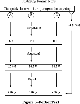 Figure 5–PortionText
_______________________________________________________________________________
»FormatOrder
In Pascal:
FormatOrder = array [0..0] of Integer;
FormatOrderPtr = ^FormatOrder;
Procedure GetFormatOrder ( ordering: FormatOrderPtr;
firstFormat: Integer;
lastFormat: Integer;
lineRight: Boolean;
RLDirProc: Ptr;
dirParam: Ptr);
In C:
typedef short FormatOrder[1];
typedef FormatOrder *FormatOrderPtr;
pascal void GetFormatOrder(FormatOrderPtr ordering,short firstFormat,
short lastFormat, Boolean lineRight,
Ptr rlDirProc, Ptr dirParam);
This routine orders the text properly for display of bidirectional format runs. Word processing programs that use this procedure for multi-font text can be independent of script text-ordering in a line (e.g., Hebrew or Arabic right-left text). The ordering points to an array of integers, with (lastFormat – firstFormat + 1) entries. The GetFormatOrder routine retrieves the direction of each format by calling the direction procedure, RLDirProc, which has the following format:
In Pascal:
Function MyRLDirProc ( theFormat : Integer; dirParam : Ptr) :Boolean;
In C:
pascal Boolean MyRLDirProc(short theFormat, Ptr dirParam);
The RLDirProc is called with the values from firstFormat to lastFormat to determine the directions of each of the format runs. It returns true for
right-left text direction, otherwise false. The parameter dirParam is available to provide other necessary information for the direction procedure
(i.e., style number, pointer to style array, etc).
GetFormatOrder returns a permuted list of the numbers from firstFormat to lastFormat. This permuted list can be used to draw or measure the text.
(For more detail, see the Script Manager developers’ packet). The lineRight parameter is true if the text is right-left orientation, otherwise false.
The array Ordering is created and filled by your application. The first element in the array should correspond to the parameter firstFormat, and the last element should correspond to lastFormat. GetFormatOrder loops through this array and passes each element in the array back to the RLDirProc function. Since you fill the ordering array and you write the RLDirProc, you should obviously store format runs in a way that makes the GetFormatOrder routine useable.
One obvious way to do this would be to declare a record type for format runs that allowed you to save things like font style, font ID, script number, and so on. You then could store these records in an array. When the time came to call GetFormatOrder, you would simply fill the Ordering array with the indexes that you used to access your array of format run records. GetFormatOrder would return an array which described the correct drawing order for your format runs.
Consider this example. Let uppercase letters stand for format runs that are left to right, and lowercase letters stand for right-left format runs. For example, there are two format runs in the following line.
1 2
ABCfed
With left-right line direction, the text should appear on the screen as:
1 2
ABCdef
With right-left line direction, the text should appear on the screen as:
2 1
fedABC
GetFormatOrder is used to tell you what order the format runs should be drawn in based on line direction for a particular line of text.
Figure 5–PortionText
_______________________________________________________________________________
»FormatOrder
In Pascal:
FormatOrder = array [0..0] of Integer;
FormatOrderPtr = ^FormatOrder;
Procedure GetFormatOrder ( ordering: FormatOrderPtr;
firstFormat: Integer;
lastFormat: Integer;
lineRight: Boolean;
RLDirProc: Ptr;
dirParam: Ptr);
In C:
typedef short FormatOrder[1];
typedef FormatOrder *FormatOrderPtr;
pascal void GetFormatOrder(FormatOrderPtr ordering,short firstFormat,
short lastFormat, Boolean lineRight,
Ptr rlDirProc, Ptr dirParam);
This routine orders the text properly for display of bidirectional format runs. Word processing programs that use this procedure for multi-font text can be independent of script text-ordering in a line (e.g., Hebrew or Arabic right-left text). The ordering points to an array of integers, with (lastFormat – firstFormat + 1) entries. The GetFormatOrder routine retrieves the direction of each format by calling the direction procedure, RLDirProc, which has the following format:
In Pascal:
Function MyRLDirProc ( theFormat : Integer; dirParam : Ptr) :Boolean;
In C:
pascal Boolean MyRLDirProc(short theFormat, Ptr dirParam);
The RLDirProc is called with the values from firstFormat to lastFormat to determine the directions of each of the format runs. It returns true for
right-left text direction, otherwise false. The parameter dirParam is available to provide other necessary information for the direction procedure
(i.e., style number, pointer to style array, etc).
GetFormatOrder returns a permuted list of the numbers from firstFormat to lastFormat. This permuted list can be used to draw or measure the text.
(For more detail, see the Script Manager developers’ packet). The lineRight parameter is true if the text is right-left orientation, otherwise false.
The array Ordering is created and filled by your application. The first element in the array should correspond to the parameter firstFormat, and the last element should correspond to lastFormat. GetFormatOrder loops through this array and passes each element in the array back to the RLDirProc function. Since you fill the ordering array and you write the RLDirProc, you should obviously store format runs in a way that makes the GetFormatOrder routine useable.
One obvious way to do this would be to declare a record type for format runs that allowed you to save things like font style, font ID, script number, and so on. You then could store these records in an array. When the time came to call GetFormatOrder, you would simply fill the Ordering array with the indexes that you used to access your array of format run records. GetFormatOrder would return an array which described the correct drawing order for your format runs.
Consider this example. Let uppercase letters stand for format runs that are left to right, and lowercase letters stand for right-left format runs. For example, there are two format runs in the following line.
1 2
ABCfed
With left-right line direction, the text should appear on the screen as:
1 2
ABCdef
With right-left line direction, the text should appear on the screen as:
2 1
fedABC
GetFormatOrder is used to tell you what order the format runs should be drawn in based on line direction for a particular line of text.
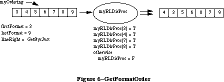 Figure 6–GetFormatOrder
For example, in Pascal:
GetFormatOrder(myOrdering,firstFormat,lastFormat,
GetSysJust = 0,MyRLDirProc,nil);
for i := 0 to lastFormat-firstFormat do
with MyFormat [myOrdering [i]], MyStyle [formatStyle] do begin
TextFont(styleFont);
{set up other text style features...}
case what of
drawing: DrawText(textStartPtr, formatStart, formatLength);
measuring: TextWidth(textStartPtr, formatStart, formatLength);
{and so on}
end; {case}
end; {with}
end; {for}
In C:
GetFormatOrder(myOrdering,firstFormat,lastFormat,(Boolean)GetSysJust(),
(Ptr)MyRLDirProc,nil);
for ( i = 0, i <= (lastFormat-firstFormat), i++)
/* set up style stuff */
switch what {
case drawing:
DrawText(textStartPtr,formatStart,formatLength);
break;
case measuring:
TextWidth(textStartPtr,formatStart,formatLength);
break;
default:
break;
}
_______________________________________________________________________________
»FindScriptRun
In Pascal:
Function FindScriptRun (textPtr: Ptr; textLen: Longint;
VAR lenUsed: Longint): ScriptRunStatus;
ScriptRunStatus = RECORD
script: SignedByte;
variant: SignedByte;
END;
In C:
pascal struct ScriptRunStatus FindScriptRun(Ptr textPtr,long textLen,
long *lenUsed);
struct ScriptRunStatus {
short script;
short variant;
};
char *mychararray = 'abcDEFghi';
char *textptr;
long textlength;
ScriptRunStatus srs;
long lenused;
srs = FindScriptRun(mychararray,(long)strlen(mychararray),&lenUsed);
/* lenUsed would now = 3, blocktype would equal 0 */
/* we can point at the remainder of the text with the following code */
textptr = mychararray + lenUsed;
textlen = strlen(mychararray) - lenUsed;
For compatibility, each script allows Roman text to be mixed in. This routine is used to break up mixed text (Roman & Native) into blocks. The lenUsed is set to reflect the length of the remaining text. The return value reflects the type of block: the upper byte is the script (0 being Roman text) and the lower byte being script-specific (script systems can return types of native sub-scripts, such as Kanji, Katakana and Hiragana for Japanese). For example, given that the capital letters represent Hebrew text:
In Pascal:
myCharArray = 'abcDEFghi';
myCharPtr := @myCharArray;
blockType := FindScriptRun (myCharPtr, 9, lenUsed);
{lenUsed = 3, blockType = 0: get remainder of text with: }
textPtr := Ptr(ord(textPtr)+lenUsed);
textLen := textLen-lenUsed;
_______________________________________________________________________________
»StyledLineBreak
In Pascal:
Function StyledLineBreak(textPtr: Ptr;
textLen: Longint;
textStart:Longint;
textEnd: Longint;
flags: Longint;
Var textWidth:Fixed; {on exit, set if too long}
Var textOffset: Longint)
:StyledLineBreakCode;
StyledLineBreakCode = (smBreakWord,smBreakChar,smBreakOverflow);
In C:
pascal StyledLineBreakCode StyledLineBreak(Ptr textPtr,long textLen,
long textStart,long textEnd,
long flags,Fixed *textWidth,
long *textOffset);
enum {smBreakWord,smBreakChar,smBreakOverflow};
typedef unsigned char StyledLineBreakCode;
This routine breaks a line on a word boundary. The user will loop through a sequence of format runs, resetting the textPtr and textLen each time the script changes; and resetting the textStart and textEnd for each format run. The textWidth will automatically be decremented by StyledLineBreak.
TextPtr points to the start of the text, textLen indicates the maximum length of the text, and the textWidth parameter indicates the maximum pixel width of the rectangle used to display the text starting at the textStart and ending at the textEnd. The flags parameter is reserved for future expansion and must be zero.
Figure 6–GetFormatOrder
For example, in Pascal:
GetFormatOrder(myOrdering,firstFormat,lastFormat,
GetSysJust = 0,MyRLDirProc,nil);
for i := 0 to lastFormat-firstFormat do
with MyFormat [myOrdering [i]], MyStyle [formatStyle] do begin
TextFont(styleFont);
{set up other text style features...}
case what of
drawing: DrawText(textStartPtr, formatStart, formatLength);
measuring: TextWidth(textStartPtr, formatStart, formatLength);
{and so on}
end; {case}
end; {with}
end; {for}
In C:
GetFormatOrder(myOrdering,firstFormat,lastFormat,(Boolean)GetSysJust(),
(Ptr)MyRLDirProc,nil);
for ( i = 0, i <= (lastFormat-firstFormat), i++)
/* set up style stuff */
switch what {
case drawing:
DrawText(textStartPtr,formatStart,formatLength);
break;
case measuring:
TextWidth(textStartPtr,formatStart,formatLength);
break;
default:
break;
}
_______________________________________________________________________________
»FindScriptRun
In Pascal:
Function FindScriptRun (textPtr: Ptr; textLen: Longint;
VAR lenUsed: Longint): ScriptRunStatus;
ScriptRunStatus = RECORD
script: SignedByte;
variant: SignedByte;
END;
In C:
pascal struct ScriptRunStatus FindScriptRun(Ptr textPtr,long textLen,
long *lenUsed);
struct ScriptRunStatus {
short script;
short variant;
};
char *mychararray = 'abcDEFghi';
char *textptr;
long textlength;
ScriptRunStatus srs;
long lenused;
srs = FindScriptRun(mychararray,(long)strlen(mychararray),&lenUsed);
/* lenUsed would now = 3, blocktype would equal 0 */
/* we can point at the remainder of the text with the following code */
textptr = mychararray + lenUsed;
textlen = strlen(mychararray) - lenUsed;
For compatibility, each script allows Roman text to be mixed in. This routine is used to break up mixed text (Roman & Native) into blocks. The lenUsed is set to reflect the length of the remaining text. The return value reflects the type of block: the upper byte is the script (0 being Roman text) and the lower byte being script-specific (script systems can return types of native sub-scripts, such as Kanji, Katakana and Hiragana for Japanese). For example, given that the capital letters represent Hebrew text:
In Pascal:
myCharArray = 'abcDEFghi';
myCharPtr := @myCharArray;
blockType := FindScriptRun (myCharPtr, 9, lenUsed);
{lenUsed = 3, blockType = 0: get remainder of text with: }
textPtr := Ptr(ord(textPtr)+lenUsed);
textLen := textLen-lenUsed;
_______________________________________________________________________________
»StyledLineBreak
In Pascal:
Function StyledLineBreak(textPtr: Ptr;
textLen: Longint;
textStart:Longint;
textEnd: Longint;
flags: Longint;
Var textWidth:Fixed; {on exit, set if too long}
Var textOffset: Longint)
:StyledLineBreakCode;
StyledLineBreakCode = (smBreakWord,smBreakChar,smBreakOverflow);
In C:
pascal StyledLineBreakCode StyledLineBreak(Ptr textPtr,long textLen,
long textStart,long textEnd,
long flags,Fixed *textWidth,
long *textOffset);
enum {smBreakWord,smBreakChar,smBreakOverflow};
typedef unsigned char StyledLineBreakCode;
This routine breaks a line on a word boundary. The user will loop through a sequence of format runs, resetting the textPtr and textLen each time the script changes; and resetting the textStart and textEnd for each format run. The textWidth will automatically be decremented by StyledLineBreak.
TextPtr points to the start of the text, textLen indicates the maximum length of the text, and the textWidth parameter indicates the maximum pixel width of the rectangle used to display the text starting at the textStart and ending at the textEnd. The flags parameter is reserved for future expansion and must be zero.
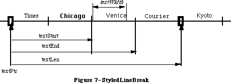 Figure 7–StyledLineBreak
On input, a non-zero textOffset indicates whether this is the first format run
(possibly forcing a character break rather than a word break: if textOffset is non-zero, at least one character will be returned if the line is not empty). On output it is the number of bytes from textPtr up to the point where the line should be broken. If the passed textWidth extended beyond the end of the text
(i.e., is larger than the width from textoffset to textLen), then the width of the text is subtracted from the textWidth and the result returned in the textWidth parameter. This can be used for the next format run.
The routine result indicates whether the routine broke on a word boundary, character boundary, or the width extended beyond the edge of the text.
When used with single-format text, the textStart can be zero, and the textEnd identical with the textLen. With multi-format text, the interval between textStart and textEnd specifies a format run. The interval between textPtr and textLen specifies a script run (a contiguous sequence of text where the script of each of the format runs is the same). Note that the format runs in StyledLineBreak must be traversed in back-end storage order, not display order
(see GetFormatOrder).
In other words, if the current format run is included in a contiguous sequence of other format runs of the same script, then the textPtr should point to the start of the first format run of the same script, while the textLen should include the last format run of the same script. This is so that word boundaries can extend across format runs; they will never extend across script runs.
Although the offsets are in longint values and widths in fixed for future extensions, in the current version the longint values should be restricted to the integer range, and only the integer portion of the widths will be used.
_______________________________________________________________________________
»VisibleLength
In Pascal:
FUNCTION VisibleLength ( textPtr : Ptr; textLen: Longint): Longint;
In C:
pascal long VisibleLength(Ptr textPtr,long textLen);
This routine returns the length of the text excluding trailing white space, taking into account the script of the text. Trailing white space is only excluded if it occurs on the visible right side, in display order.
Figure 7–StyledLineBreak
On input, a non-zero textOffset indicates whether this is the first format run
(possibly forcing a character break rather than a word break: if textOffset is non-zero, at least one character will be returned if the line is not empty). On output it is the number of bytes from textPtr up to the point where the line should be broken. If the passed textWidth extended beyond the end of the text
(i.e., is larger than the width from textoffset to textLen), then the width of the text is subtracted from the textWidth and the result returned in the textWidth parameter. This can be used for the next format run.
The routine result indicates whether the routine broke on a word boundary, character boundary, or the width extended beyond the edge of the text.
When used with single-format text, the textStart can be zero, and the textEnd identical with the textLen. With multi-format text, the interval between textStart and textEnd specifies a format run. The interval between textPtr and textLen specifies a script run (a contiguous sequence of text where the script of each of the format runs is the same). Note that the format runs in StyledLineBreak must be traversed in back-end storage order, not display order
(see GetFormatOrder).
In other words, if the current format run is included in a contiguous sequence of other format runs of the same script, then the textPtr should point to the start of the first format run of the same script, while the textLen should include the last format run of the same script. This is so that word boundaries can extend across format runs; they will never extend across script runs.
Although the offsets are in longint values and widths in fixed for future extensions, in the current version the longint values should be restricted to the integer range, and only the integer portion of the widths will be used.
_______________________________________________________________________________
»VisibleLength
In Pascal:
FUNCTION VisibleLength ( textPtr : Ptr; textLen: Longint): Longint;
In C:
pascal long VisibleLength(Ptr textPtr,long textLen);
This routine returns the length of the text excluding trailing white space, taking into account the script of the text. Trailing white space is only excluded if it occurs on the visible right side, in display order.
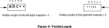 Figure 8–VisibleLength
For example, in Pascal:
myVisibleLength := VisibleLength(myText,myOffset);
curSlop := myPixel - TextWidth(myText,0,myVisibleLength);
DrawJust(myText,myVisibleLength,curSlop);
_______________________________________________________________________________
»UprText and LwrText
In Pascal:
Procedure UprText(textPtr: Ptr; len: Integer);
Procedure LwrText(textPtr: Ptr; len: Integer);
In C:
pascal void UprText(Ptr textPtr,short len);
pascal void LwrText(Ptr textPtr,short len);
UprText provides a Pascal interface to the _UprString assembly routine, which will uppercase text up to 32K in length. The LwrText routine provides the corresponding lowercase routine. Both of these routines will not change the number or position of characters in a string, but are faster and simpler than the Transliterate routine.
_______________________________________________________________________________
»Text Comparison
We have done some performance analyses of Pack6 comparison routines, and based upon those, were able to increase performance by about 50% on average. This increase results in a corresponding increase in 4th Dimension sorting performance, for example. Also, a long-standing bug in sorting “œ” and “æ” has been corrected. A test program on the Macintosh SE comparing “The quick brown fox jumped over the lazy dog” to variants produced the following decreases in comparison time:
Identical text: 94%
Last Character Unequal (g vs. X) 83%
Last Character Weakly Equal (g vs. G): 82%
First Character Unequal (T vs X): 59%
First Character Weakly Equal (T vs t): 29%
All Characters Weakly Equal (T vs t…g vs. G): 25%
Part of the performance increase results from internal caching of 'itl ' resources. Originally all 'itl ' resources (resulting from IUGetIntl of 0,1,2,4) were cached, but several programs do a _ReleaseResource or
_DetachResource on 'itl0', rendering the cache invalid. Because of this, currently only 'itl2' and 'itl4' are cached. Developers must be sure not to release or detach these resources. Also, only the system file resources are used, so they cannot be overridden by copies in the application or document resource forks.
Figure 8–VisibleLength
For example, in Pascal:
myVisibleLength := VisibleLength(myText,myOffset);
curSlop := myPixel - TextWidth(myText,0,myVisibleLength);
DrawJust(myText,myVisibleLength,curSlop);
_______________________________________________________________________________
»UprText and LwrText
In Pascal:
Procedure UprText(textPtr: Ptr; len: Integer);
Procedure LwrText(textPtr: Ptr; len: Integer);
In C:
pascal void UprText(Ptr textPtr,short len);
pascal void LwrText(Ptr textPtr,short len);
UprText provides a Pascal interface to the _UprString assembly routine, which will uppercase text up to 32K in length. The LwrText routine provides the corresponding lowercase routine. Both of these routines will not change the number or position of characters in a string, but are faster and simpler than the Transliterate routine.
_______________________________________________________________________________
»Text Comparison
We have done some performance analyses of Pack6 comparison routines, and based upon those, were able to increase performance by about 50% on average. This increase results in a corresponding increase in 4th Dimension sorting performance, for example. Also, a long-standing bug in sorting “œ” and “æ” has been corrected. A test program on the Macintosh SE comparing “The quick brown fox jumped over the lazy dog” to variants produced the following decreases in comparison time:
Identical text: 94%
Last Character Unequal (g vs. X) 83%
Last Character Weakly Equal (g vs. G): 82%
First Character Unequal (T vs X): 59%
First Character Weakly Equal (T vs t): 29%
All Characters Weakly Equal (T vs t…g vs. G): 25%
Part of the performance increase results from internal caching of 'itl ' resources. Originally all 'itl ' resources (resulting from IUGetIntl of 0,1,2,4) were cached, but several programs do a _ReleaseResource or
_DetachResource on 'itl0', rendering the cache invalid. Because of this, currently only 'itl2' and 'itl4' are cached. Developers must be sure not to release or detach these resources. Also, only the system file resources are used, so they cannot be overridden by copies in the application or document resource forks.
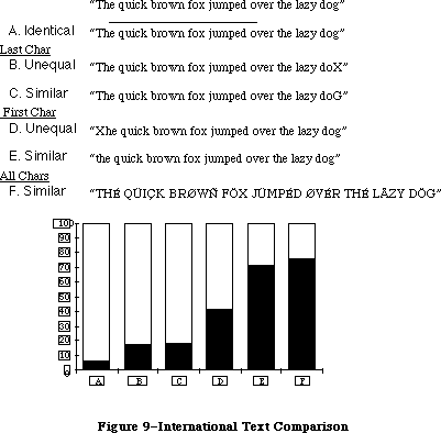 Figure 9–International Text Comparison
The Macintosh date routines are extended to provide a larger range (roughly 35 thousand years), and more information. This extension allows programs that need a larger range of dates to use system routines rather than produce their own, which may not be internationally compatible. The programmer can also access the stored location (latitude and longitude) and time zone of the Macintosh from parameter RAM. The Map cdev gives users the ability to change and reference these values.
The long internal format of a date is as before, in seconds since 12:00 midnight, January 1, 1904, but is represented as a signed 64-bit integer (SANE Comp format), allowing a somewhat larger range (roughly 500 billion years). Short internal format dates (since they are unsigned) can be converted to long format by filling the top 32 bits with zero; long formats can be converted to short by truncating (assuming that they are within range). When storing in files, a five (or six) byte format can be used for a range of roughly 35 thousand years. This value should be sign-extended to restore it to a Comp format.
_______________________________________________________________________________
»LongDateTime
In Pascal:
Type LongDateTime = Comp;
In C:
typedef comp LongDateTime;
The standard date conversion record is extended using a new structure:
In Pascal:
LongDateRec = Record
case Integer of
0: ( era,year,month,day,hour,minute,second,
dayOfWeek,dayOfYear,weekOfYear,
pm,res1,res2,res3: Integer);
1: ( list: array [longDateField] of Integer);
2: ( eraAlt: Integer;
oldDate: DateTimeRec);
end;
In C:
union LongDateRec {
struct {
short era;
short year;
short month;
short day;
short hour;
short minute;
short second;
short dayOfWeek;
short dayOfYear;
short weekOfYear;
short pm;
short res1;
short res2;
short res3;
} ld;
short list[14]; /*Index by LongDateField!*/
struct {
short eraAlt;
DateTimeRec oldDate;
} od;
};
The default calendar for converting to and from the long internal format is the Gregorian calendar. The era field for this calendar has values 0 for A.D. and
-1 for B.C. (Note that the international date string conversion routines do not append strings for A.D. or B.C.) The current range allowed in conversion is roughly 30,000 BC to 30,000 AD.
(Note that in different countries the change from the Julian calendar to Gregorian calendar occurred in different years: in Catholic countries, it occurred in 1582, while in Russia it took place as late as 1917. Dates before these years in those countries should use the Julian calendar for conversion. The Julian calendar differs from the Gregorian by three days every four centuries.)
Figure 9–International Text Comparison
The Macintosh date routines are extended to provide a larger range (roughly 35 thousand years), and more information. This extension allows programs that need a larger range of dates to use system routines rather than produce their own, which may not be internationally compatible. The programmer can also access the stored location (latitude and longitude) and time zone of the Macintosh from parameter RAM. The Map cdev gives users the ability to change and reference these values.
The long internal format of a date is as before, in seconds since 12:00 midnight, January 1, 1904, but is represented as a signed 64-bit integer (SANE Comp format), allowing a somewhat larger range (roughly 500 billion years). Short internal format dates (since they are unsigned) can be converted to long format by filling the top 32 bits with zero; long formats can be converted to short by truncating (assuming that they are within range). When storing in files, a five (or six) byte format can be used for a range of roughly 35 thousand years. This value should be sign-extended to restore it to a Comp format.
_______________________________________________________________________________
»LongDateTime
In Pascal:
Type LongDateTime = Comp;
In C:
typedef comp LongDateTime;
The standard date conversion record is extended using a new structure:
In Pascal:
LongDateRec = Record
case Integer of
0: ( era,year,month,day,hour,minute,second,
dayOfWeek,dayOfYear,weekOfYear,
pm,res1,res2,res3: Integer);
1: ( list: array [longDateField] of Integer);
2: ( eraAlt: Integer;
oldDate: DateTimeRec);
end;
In C:
union LongDateRec {
struct {
short era;
short year;
short month;
short day;
short hour;
short minute;
short second;
short dayOfWeek;
short dayOfYear;
short weekOfYear;
short pm;
short res1;
short res2;
short res3;
} ld;
short list[14]; /*Index by LongDateField!*/
struct {
short eraAlt;
DateTimeRec oldDate;
} od;
};
The default calendar for converting to and from the long internal format is the Gregorian calendar. The era field for this calendar has values 0 for A.D. and
-1 for B.C. (Note that the international date string conversion routines do not append strings for A.D. or B.C.) The current range allowed in conversion is roughly 30,000 BC to 30,000 AD.
(Note that in different countries the change from the Julian calendar to Gregorian calendar occurred in different years: in Catholic countries, it occurred in 1582, while in Russia it took place as late as 1917. Dates before these years in those countries should use the Julian calendar for conversion. The Julian calendar differs from the Gregorian by three days every four centuries.)
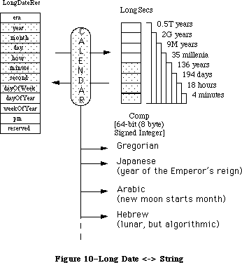 Figure 10–Long Date <-> String
_______________________________________________________________________________
»InitDateCache
In Pascal:
Function InitDateCache (theCache: DateCachePtr): OSErr;
In C:
pascal OSErr InitDateCache(DateCachePtr theCache);
This routine must be called before using the String2Date or String2Time routines to format the theCache record. Allocation of this record is the responsibility of the caller: it can either be a local variable, a Ptr or a locked Handle. By using this cache, the performance of the String2Date and String2Time routines is improved.
In Pascal:
Procedure MyRoutine;
Var
myCache: DateCacheRecord;
Begin
InitDateCache (@myCache);
{call the String2Date or Time routines. Note that if you are }
{ doing this inside an application where global variables are }
{ allowed, you should probably make your Date cache a global and }
{ initialize it once, when you initialize the Toolbox Managers.}
End;
In C:
void MyRoutine()
{
DateCacheRecord myCache;
InitDateCache(&myCache);
/* Now you can call String2Date or String2Time, Note that if you
are doing this inside an application where global variables are
allowed, you should probably make your Date cache a global and
initialize it once when you initialize the Toolbox managers
*/
}
_______________________________________________________________________________
»String2Date and String2Time
In Pascal:
Function String2Date(textPtr: Ptr;
textLen: longint;
theCache: DateCachePtr;
Var lengthUsed: Longint;
Var dateTime: LongDateRec)
: String2DateStatus;
Function String2Time(textPtr: Ptr;
textLen: longint;
theCache: DateCachePtr;
Var lengthUsed: Longint;
Var dateTime: LongDateRec)
: String2DateStatus;
In C:
pascal String2DateStatus String2Date(Ptr textPtr,long textLen,
DateCachePtr theCache, long *lengthUsed,
LongDateRec *dateTime);
pascal String2DateStatus String2Time(Ptr textPtr,long textLen,
DateCachePtr theCache, long *lengthUsed,
LongDateRec *dateTime);
These routines expect a date and time at the beginning of the text. They parse the text, setting the lengthUsed to reflect the remainder of the text, and fill the dateTime record. They recognize all the strings that are produced by the international date and time utilities, and others. For example, they will recognize the following dates: September 1, 1987; 1 Sept 1987; 1/9/1987; and 1 1987 sEpT.
If the value of the input year is less than 100, then it is added to 1900; if less than 1000, then it is added to 1000 (the appropriate values are used from other calendars, gotten from the base date: LongDateTime = 0). Thus the dates 1/9/1987 and 1/9/87 are equivalent.
The routines use the following grammar to interpret the date and time. The relevant fields of the international utilities resources are used for separators, month and weekday names, and the ordering of the date elements. The parsing is actually semantic-driven, so finer distinctions are made than those represented in the syntax diagram.
time := number [tSep number [tSep number]] [mornStr | eveStr | timeSuff]
tSep := timeSep | sep
date := [dSep] dField [dSep dField [dSep dField [dSep dField [dSep]]]]
dField := number | dayOfWeek | abbrevMonth | month
dSep := dateSep | st0 | st1 | st2 | st3 | st4 | sep
sep := <non-alphanumeric>
The date defaults are the current day, month and year. The time defaults to
00:00:00. The digits in a year are padded on the left, using the base date
(the date corresponding to zero seconds: Jan 1, 1904). This routine uses the tokenizer to separate the components of the strings. It depends upon the names of the months and weekdays used from international resources being single alphanumeric tokens.
Note that the date routine only fills in the year, month, day and dayOfWeek; the time routine fills in only the hour, minute and second. Thus the two routines can be called sequentially to fill complementary values in the LongDateRec.
The return from the routine is a set of bits that indicate confidence levels, with higher numbers indicating low confidence in how closely the input string matched what the routine expected. For example, inputting a time of 12.43.36 will work, but return a message indicating that the separator was not standard. This can also be used to parse a string containing both the date and time, by using the confidence levels to determine which portion comes first. The returned bits include:
In Pascal:
fatalDateTime = $8000;
longDateFound = 1;
leftOverChars = 2;
sepNotIntlSep = 4;
fieldOrderNotIntl = 8;
extraneousStrings = 16;
tooManySeps = 32;
sepNotConsistent = 64;
tokenErr = $8100;
cantReadUtilities = $8200;
dateTimeNotFound = $8400;
dateTimeInvalid = $8800;
In C:
#define fatalDateTime 0x8000
#define longDateFound 1
#define leftOverChars 2
#define sepNotIntlSep 4
#define fieldOrderNotIntl 8
#define extraneousStrings 16
#define tooManySeps 32
#define sepNotConsistent 64
#define tokenErr 0x8100
#define cantReadUtilities 0x8200
#define dateTimeNotFound 0x8400
#define dateTimeInvalid 0x8800
_______________________________________________________________________________
»LongDate2Secs and LongSecs2Date
In Pascal:
Procedure LongDate2Secs(lDate: LongDateRec; Var lSecs: LongDateTime);
Procedure LongSecs2Date(lSecs: LongDateTime; Var lDate: LongDateRec);
In C:
pascal void LongDate2Secs(const LongDateRec *lDate,LongDateTime *lSecs);
pascal void LongSecs2Date(LongDateTime *lSecs,LongDateRec *lDate);
These routines extend the range of the Macintosh calendar as discussed above. Any fields that are not used should be zeroed. On input, the LongDate2Secs routine will use the day and month unless the day is zero; otherwise the dayOfYear is used unless it is zero; otherwise the dayOfWeek and weekOfYear are used.
Other fields are additive: if you supply a month of 37, that will be interpreted as adding 3 to the year, and using a month of 1. This latter property is subject to some restrictions imposed by the internal arithmetic: for example, | hour*60+minute | must be less than 32767.
Two new interfaces have been added to Pack6 for LongDate support:
In Pascal:
IULDateString(dateTime: LongDateTime; form: DateForm; Var Result: Str255;
intlParam: Handle);
Assembly selector: 20
IULTimeString(dateTime: LongDateTime; wantSeconds: BOOLEAN; Var Result:Str255;
intlParam: Handle);
Assembly selector: 22
In C:
pascal void IULDateString(LongDateTime *dateTime,DateForm longFlag,
Str255 result, Handle intlParam);
pascal void IULTimeString(LongDateTime *dateTime,Boolean wantSeconds,
Str255 result, Handle intlParam);
These routines take a LongDateTime, and return a formatted string. Only the old fields year..second, and dayOfWeek are used. If the intlParam is zero, then the international resource 0 ('itl0') is used. The output year is limited to four digits: e.g., from 1 to 9999 A.D.
_______________________________________________________________________________
»ToggleDate and ValidDate
In Pascal:
Function ToggleDate (Var mySecs: LongDateTime; field: LongDateField;
delta: DateDelta; ch: Integer;
params: TogglePB) :ToggleResults;
Function ValidDate (Var date : LongDateRec; flags: Longint;
Var newSecs: LongDateTime) : Integer;
In C:
pascal ToggleResults ToggleDate(LongDateTime *lSecs,LongDateField field,
DateDelta delta,short ch,
const TogglePB *params);
pascal short ValidDate(LongDateRec *vDate,long flags,LongDateTime *newSecs);
The ToggleDate routine is used to modify a date or time record by toggling one of the fields up or down. The routine returns a valid date by performing two types of action. If the affected field overflows or underflows, then it will wrap to the corresponding low or high value. If changing the affected field causes other fields to be invalid, then a close date is selected (which may cause other fields to change). For example, toggling the year upwards in February 29, 1980 results in March 1, 1981. Currently only the fields year..second, and am can be toggled, although this should change in the future.
The routine will also toggle by character, if the delta = 0. The character will be used to change the field in the following way. If it is a digit, then it will be added to the end of the field, and the field will be then modified to be valid in a similar manner as in the alarm clock. For example, if the minute is 54, then to replace it by 23 by entering characters, first the minute will change to 42, then to 23. The AM/PM field will also use letters.
In Pascal:
TogglePB = RECORD
togFlags: LONGINT;
amChars: ResType; {from intl0}
pmChars: ResType; {from intl0}
reserved: ARRAY [0..3] OF LONGINT;
END;
In C:
struct TogglePB {
long togFlags;
ResType amChars; /*from intl0*/
ResType pmChars; /*from intl0*/
long reserved[4];
};
The parameter block should be set up as follows. It should contain the uppercase versions of the AM and PM strings to match (the defaults mornStr and eveStr can be copied from the international utilities using IUGetIntl, and converted to uppercase with UprText).
The ToggleDate routine makes an internal call to ValidDate, which can also be called directly by the user. ValidDate checks the date record for correctness, using the params.togflags which is passed to it by ToggleDate. If any of the record fields are invalid, ValidDate returns a DateField value corresponding to the field in error. Otherwise, it returns a -1.
The params.togflags value passed to ValidDate by ToggleDate are the same for ToggleDate and ValidDate. The low word bits correspond to the values in the enumerated type DateField. For example, to check the validity of the year field you can create a mask by doing the following:
yearFieldMask = 2**yearField;
The high word of the flags value can be used to set various other conditions. The only one currently used is a flag which can be set to restrict the range of valid dates to the short date format (smallDateBit = 31; smallDateMask = $80000000). All other bits are reserved, and should be set to zero. The reserved values should also be zeroed.
Togflags should normally be set to $007F, which can be done by using the predeclared constant dateStdMask.
Figure 10–Long Date <-> String
_______________________________________________________________________________
»InitDateCache
In Pascal:
Function InitDateCache (theCache: DateCachePtr): OSErr;
In C:
pascal OSErr InitDateCache(DateCachePtr theCache);
This routine must be called before using the String2Date or String2Time routines to format the theCache record. Allocation of this record is the responsibility of the caller: it can either be a local variable, a Ptr or a locked Handle. By using this cache, the performance of the String2Date and String2Time routines is improved.
In Pascal:
Procedure MyRoutine;
Var
myCache: DateCacheRecord;
Begin
InitDateCache (@myCache);
{call the String2Date or Time routines. Note that if you are }
{ doing this inside an application where global variables are }
{ allowed, you should probably make your Date cache a global and }
{ initialize it once, when you initialize the Toolbox Managers.}
End;
In C:
void MyRoutine()
{
DateCacheRecord myCache;
InitDateCache(&myCache);
/* Now you can call String2Date or String2Time, Note that if you
are doing this inside an application where global variables are
allowed, you should probably make your Date cache a global and
initialize it once when you initialize the Toolbox managers
*/
}
_______________________________________________________________________________
»String2Date and String2Time
In Pascal:
Function String2Date(textPtr: Ptr;
textLen: longint;
theCache: DateCachePtr;
Var lengthUsed: Longint;
Var dateTime: LongDateRec)
: String2DateStatus;
Function String2Time(textPtr: Ptr;
textLen: longint;
theCache: DateCachePtr;
Var lengthUsed: Longint;
Var dateTime: LongDateRec)
: String2DateStatus;
In C:
pascal String2DateStatus String2Date(Ptr textPtr,long textLen,
DateCachePtr theCache, long *lengthUsed,
LongDateRec *dateTime);
pascal String2DateStatus String2Time(Ptr textPtr,long textLen,
DateCachePtr theCache, long *lengthUsed,
LongDateRec *dateTime);
These routines expect a date and time at the beginning of the text. They parse the text, setting the lengthUsed to reflect the remainder of the text, and fill the dateTime record. They recognize all the strings that are produced by the international date and time utilities, and others. For example, they will recognize the following dates: September 1, 1987; 1 Sept 1987; 1/9/1987; and 1 1987 sEpT.
If the value of the input year is less than 100, then it is added to 1900; if less than 1000, then it is added to 1000 (the appropriate values are used from other calendars, gotten from the base date: LongDateTime = 0). Thus the dates 1/9/1987 and 1/9/87 are equivalent.
The routines use the following grammar to interpret the date and time. The relevant fields of the international utilities resources are used for separators, month and weekday names, and the ordering of the date elements. The parsing is actually semantic-driven, so finer distinctions are made than those represented in the syntax diagram.
time := number [tSep number [tSep number]] [mornStr | eveStr | timeSuff]
tSep := timeSep | sep
date := [dSep] dField [dSep dField [dSep dField [dSep dField [dSep]]]]
dField := number | dayOfWeek | abbrevMonth | month
dSep := dateSep | st0 | st1 | st2 | st3 | st4 | sep
sep := <non-alphanumeric>
The date defaults are the current day, month and year. The time defaults to
00:00:00. The digits in a year are padded on the left, using the base date
(the date corresponding to zero seconds: Jan 1, 1904). This routine uses the tokenizer to separate the components of the strings. It depends upon the names of the months and weekdays used from international resources being single alphanumeric tokens.
Note that the date routine only fills in the year, month, day and dayOfWeek; the time routine fills in only the hour, minute and second. Thus the two routines can be called sequentially to fill complementary values in the LongDateRec.
The return from the routine is a set of bits that indicate confidence levels, with higher numbers indicating low confidence in how closely the input string matched what the routine expected. For example, inputting a time of 12.43.36 will work, but return a message indicating that the separator was not standard. This can also be used to parse a string containing both the date and time, by using the confidence levels to determine which portion comes first. The returned bits include:
In Pascal:
fatalDateTime = $8000;
longDateFound = 1;
leftOverChars = 2;
sepNotIntlSep = 4;
fieldOrderNotIntl = 8;
extraneousStrings = 16;
tooManySeps = 32;
sepNotConsistent = 64;
tokenErr = $8100;
cantReadUtilities = $8200;
dateTimeNotFound = $8400;
dateTimeInvalid = $8800;
In C:
#define fatalDateTime 0x8000
#define longDateFound 1
#define leftOverChars 2
#define sepNotIntlSep 4
#define fieldOrderNotIntl 8
#define extraneousStrings 16
#define tooManySeps 32
#define sepNotConsistent 64
#define tokenErr 0x8100
#define cantReadUtilities 0x8200
#define dateTimeNotFound 0x8400
#define dateTimeInvalid 0x8800
_______________________________________________________________________________
»LongDate2Secs and LongSecs2Date
In Pascal:
Procedure LongDate2Secs(lDate: LongDateRec; Var lSecs: LongDateTime);
Procedure LongSecs2Date(lSecs: LongDateTime; Var lDate: LongDateRec);
In C:
pascal void LongDate2Secs(const LongDateRec *lDate,LongDateTime *lSecs);
pascal void LongSecs2Date(LongDateTime *lSecs,LongDateRec *lDate);
These routines extend the range of the Macintosh calendar as discussed above. Any fields that are not used should be zeroed. On input, the LongDate2Secs routine will use the day and month unless the day is zero; otherwise the dayOfYear is used unless it is zero; otherwise the dayOfWeek and weekOfYear are used.
Other fields are additive: if you supply a month of 37, that will be interpreted as adding 3 to the year, and using a month of 1. This latter property is subject to some restrictions imposed by the internal arithmetic: for example, | hour*60+minute | must be less than 32767.
Two new interfaces have been added to Pack6 for LongDate support:
In Pascal:
IULDateString(dateTime: LongDateTime; form: DateForm; Var Result: Str255;
intlParam: Handle);
Assembly selector: 20
IULTimeString(dateTime: LongDateTime; wantSeconds: BOOLEAN; Var Result:Str255;
intlParam: Handle);
Assembly selector: 22
In C:
pascal void IULDateString(LongDateTime *dateTime,DateForm longFlag,
Str255 result, Handle intlParam);
pascal void IULTimeString(LongDateTime *dateTime,Boolean wantSeconds,
Str255 result, Handle intlParam);
These routines take a LongDateTime, and return a formatted string. Only the old fields year..second, and dayOfWeek are used. If the intlParam is zero, then the international resource 0 ('itl0') is used. The output year is limited to four digits: e.g., from 1 to 9999 A.D.
_______________________________________________________________________________
»ToggleDate and ValidDate
In Pascal:
Function ToggleDate (Var mySecs: LongDateTime; field: LongDateField;
delta: DateDelta; ch: Integer;
params: TogglePB) :ToggleResults;
Function ValidDate (Var date : LongDateRec; flags: Longint;
Var newSecs: LongDateTime) : Integer;
In C:
pascal ToggleResults ToggleDate(LongDateTime *lSecs,LongDateField field,
DateDelta delta,short ch,
const TogglePB *params);
pascal short ValidDate(LongDateRec *vDate,long flags,LongDateTime *newSecs);
The ToggleDate routine is used to modify a date or time record by toggling one of the fields up or down. The routine returns a valid date by performing two types of action. If the affected field overflows or underflows, then it will wrap to the corresponding low or high value. If changing the affected field causes other fields to be invalid, then a close date is selected (which may cause other fields to change). For example, toggling the year upwards in February 29, 1980 results in March 1, 1981. Currently only the fields year..second, and am can be toggled, although this should change in the future.
The routine will also toggle by character, if the delta = 0. The character will be used to change the field in the following way. If it is a digit, then it will be added to the end of the field, and the field will be then modified to be valid in a similar manner as in the alarm clock. For example, if the minute is 54, then to replace it by 23 by entering characters, first the minute will change to 42, then to 23. The AM/PM field will also use letters.
In Pascal:
TogglePB = RECORD
togFlags: LONGINT;
amChars: ResType; {from intl0}
pmChars: ResType; {from intl0}
reserved: ARRAY [0..3] OF LONGINT;
END;
In C:
struct TogglePB {
long togFlags;
ResType amChars; /*from intl0*/
ResType pmChars; /*from intl0*/
long reserved[4];
};
The parameter block should be set up as follows. It should contain the uppercase versions of the AM and PM strings to match (the defaults mornStr and eveStr can be copied from the international utilities using IUGetIntl, and converted to uppercase with UprText).
The ToggleDate routine makes an internal call to ValidDate, which can also be called directly by the user. ValidDate checks the date record for correctness, using the params.togflags which is passed to it by ToggleDate. If any of the record fields are invalid, ValidDate returns a DateField value corresponding to the field in error. Otherwise, it returns a -1.
The params.togflags value passed to ValidDate by ToggleDate are the same for ToggleDate and ValidDate. The low word bits correspond to the values in the enumerated type DateField. For example, to check the validity of the year field you can create a mask by doing the following:
yearFieldMask = 2**yearField;
The high word of the flags value can be used to set various other conditions. The only one currently used is a flag which can be set to restrict the range of valid dates to the short date format (smallDateBit = 31; smallDateMask = $80000000). All other bits are reserved, and should be set to zero. The reserved values should also be zeroed.
Togflags should normally be set to $007F, which can be done by using the predeclared constant dateStdMask.
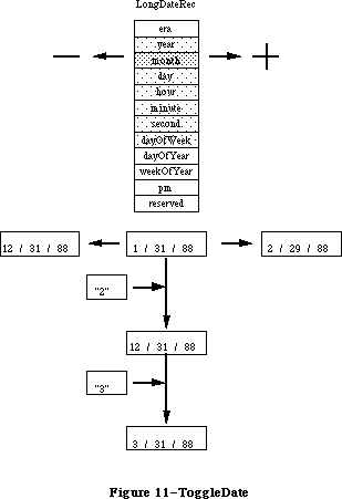 Figure 11–ToggleDate
_______________________________________________________________________________
»ReadLocation and WriteLocation
In Pascal:
PROCEDURE ReadLocation(VAR loc: MachineLocation);
PROCEDURE WriteLocation(loc: MachineLocation);
In C:
pascal void ReadLocation(MachineLocation *loc);
pascal void WriteLocation(const MachineLocation *loc);
These routines allow the programmer to access the stored geographic location of the Macintosh and time zone information from parameter RAM. For example, the time zone information can be used to derive the absolute time (GMT) that a document or mail message was created. With this information, when the document is received across time zones, the creation date and time are correct. Otherwise, documents can appear to be created after” they are read (e.g., I can create a message in Tokyo on Tuesday and send it to Cupertino, where it is received and read on Monday). Geographic information can also be used by applications which require it.
If the MachineLocation has never been set, then it should be <0,0,0>. The top byte of the gmtDelta should be masked off and preserved when writing: it is reserved for future extension. The gmtDelta is in seconds east of GMT: e.g., San Francisco is at minus 28,800 seconds (8 hours * 3600 seconds per hour). The latitude and longitude are in fractions of a great circle, giving them accuracy to within less than a foot, which should be sufficient for most purposes. For example, Fract values of 1.0 = 90°, -1.0 = -90°, -2.0 = -180°.
In Pascal:
MachineLocation = RECORD
latitude: Fract;
longitude: Fract;
CASE INTEGER OF
0:
(dlsDelta: SignedByte);
{signed byte; daylight savings delta}
1:
(gmtDelta: LONGINT);
{must mask - see documentation}
END;
In C:
struct MachineLocation {
Fract latitude;
Fract longitude;
union{
char dlsDelta; /*signed byte; daylight savings delta*/
long gmtDelta; /*must mask - see documentation*/
} gmtFlags;
};
The gmtDelta is really a three-byte value, so the user must take care to get and set it properly as in the following code examples:
In Pascal:
Function GetGmtDelta(myLocation: MachineLocation): longint;
Var
internalGmtDelta: Longint;
begin
With myLocation Do Begin
internalGmtDelta := BAnd(gmtDelta,$00FFFFFF); {get value}
If BTst(internalGmtDelta,23) {sign extend}
Then internalGmtDelta := BOr(internalGmtDelta,$FF000000);
GetGmtDelta := internalGmtDelta;
End;
End;
Procedure SetGmtDelta(Var myLocation: Location; myGmtDelta: Longint);
Var
tempSignedByte: SignedByte;
BEGIN
WITH myLocation DO BEGIN
tempSignedByte := dlsDelta;
gmtDelta := myGmtDelta;
dlsDelta := tempSignedByte;
END;
END;
In C:
long GetGmtDelta(MachineLocation myLocation)
{
long internalGMTDelta;
internalGMTDelta = myLocation.gmtDelta & 0x00ffffff;
if ( (internalGMTDelta >> 23) & 1 ) // need to sign extend
internalGmtDelta = internalGmtDelta | 0xff000000;
return(internalGmtDelta);
}
void SetGmtDelta(MachineLocation *myLocation, long myGmtDelta)
{
char tempSignedByte;
tempSignedByte = myLocation->dlsDelta;
myLocation->gmtDelta = myGmtDelta;
myLocation->dlsDelta = tempSignedByte;
}
Figure 11–ToggleDate
_______________________________________________________________________________
»ReadLocation and WriteLocation
In Pascal:
PROCEDURE ReadLocation(VAR loc: MachineLocation);
PROCEDURE WriteLocation(loc: MachineLocation);
In C:
pascal void ReadLocation(MachineLocation *loc);
pascal void WriteLocation(const MachineLocation *loc);
These routines allow the programmer to access the stored geographic location of the Macintosh and time zone information from parameter RAM. For example, the time zone information can be used to derive the absolute time (GMT) that a document or mail message was created. With this information, when the document is received across time zones, the creation date and time are correct. Otherwise, documents can appear to be created after” they are read (e.g., I can create a message in Tokyo on Tuesday and send it to Cupertino, where it is received and read on Monday). Geographic information can also be used by applications which require it.
If the MachineLocation has never been set, then it should be <0,0,0>. The top byte of the gmtDelta should be masked off and preserved when writing: it is reserved for future extension. The gmtDelta is in seconds east of GMT: e.g., San Francisco is at minus 28,800 seconds (8 hours * 3600 seconds per hour). The latitude and longitude are in fractions of a great circle, giving them accuracy to within less than a foot, which should be sufficient for most purposes. For example, Fract values of 1.0 = 90°, -1.0 = -90°, -2.0 = -180°.
In Pascal:
MachineLocation = RECORD
latitude: Fract;
longitude: Fract;
CASE INTEGER OF
0:
(dlsDelta: SignedByte);
{signed byte; daylight savings delta}
1:
(gmtDelta: LONGINT);
{must mask - see documentation}
END;
In C:
struct MachineLocation {
Fract latitude;
Fract longitude;
union{
char dlsDelta; /*signed byte; daylight savings delta*/
long gmtDelta; /*must mask - see documentation*/
} gmtFlags;
};
The gmtDelta is really a three-byte value, so the user must take care to get and set it properly as in the following code examples:
In Pascal:
Function GetGmtDelta(myLocation: MachineLocation): longint;
Var
internalGmtDelta: Longint;
begin
With myLocation Do Begin
internalGmtDelta := BAnd(gmtDelta,$00FFFFFF); {get value}
If BTst(internalGmtDelta,23) {sign extend}
Then internalGmtDelta := BOr(internalGmtDelta,$FF000000);
GetGmtDelta := internalGmtDelta;
End;
End;
Procedure SetGmtDelta(Var myLocation: Location; myGmtDelta: Longint);
Var
tempSignedByte: SignedByte;
BEGIN
WITH myLocation DO BEGIN
tempSignedByte := dlsDelta;
gmtDelta := myGmtDelta;
dlsDelta := tempSignedByte;
END;
END;
In C:
long GetGmtDelta(MachineLocation myLocation)
{
long internalGMTDelta;
internalGMTDelta = myLocation.gmtDelta & 0x00ffffff;
if ( (internalGMTDelta >> 23) & 1 ) // need to sign extend
internalGmtDelta = internalGmtDelta | 0xff000000;
return(internalGmtDelta);
}
void SetGmtDelta(MachineLocation *myLocation, long myGmtDelta)
{
char tempSignedByte;
tempSignedByte = myLocation->dlsDelta;
myLocation->gmtDelta = myGmtDelta;
myLocation->dlsDelta = tempSignedByte;
}
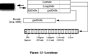 Figure 12–Locations
_______________________________________________________________________________
»Setting Latitude, Longitude, and Time Zone cdev
This new Control Panel module on the utilities disk allows the user to set the latitude, longitude, and time zone. The values are stored in parameter RAM on the host machine. (See the Map cdev documentation for more details).
Figure 12–Locations
_______________________________________________________________________________
»Setting Latitude, Longitude, and Time Zone cdev
This new Control Panel module on the utilities disk allows the user to set the latitude, longitude, and time zone. The values are stored in parameter RAM on the host machine. (See the Map cdev documentation for more details).
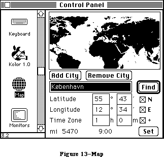 Figure 13–Map
The new number routines supplement SANE, allowing applications to display formatted numbers in the manner of Microsoft Excel or Fourth Dimension, and to read both formatted and simple numbers. The formatting strings allow natural display and entry of numbers and editing of format strings even though the original numbers and the format strings were entered in a language other than that of the final user.
Number parsing is based on a NumberParts table that describes the essentials of numeric display for a particular language, including such components as thousands separator, decimal point, scientific notation, forced zeroes in the absence of significant digits, etc. A default NumberParts table for each locale’s system resides in the 'itl4' resource for that system.
_______________________________________________________________________________
»NumberParts
In Pascal:
NumberParts = RECORD
version: integer;
data: array [tokLeftQuote..tokMaxSymbols] OF WideChar;
pePlus,peMinus,peMinusPlus: WideCharArr;
altNumTable: WideCharArr;
reserved: packed array [0..19] of Char; (must be zeroed!}
END;
In C:
struct NumberParts {
short version;
WideChar data[31]; /*index by [tokLeftQuote..tokMaxSymbols]*/
WideCharArr pePlus;
WideCharArr peMinus;
WideCharArr peMinusPlus;
WideCharArr altNumTable;
char reserved[20];
};
Here is an example of how to access the 'itl4' default NumberParts table:
In Pascal:
Function DefaultParts( Var x: NumberParts ): Boolean;
Var
itl4: Itl4Handle;
Begin
DefaultParts := false; {assume error}
itl4 := itl4Handle(IUGetIntl(4)); {get itl4 record}
if itl4 <> nil then begin {if ok}
x := NumberPartsPtr(ord(itl4^)+itl4^^.defPartsOffset)^;
{numberParts subtable}
DefaultParts := true; {no error}
end;
End;
In C:
DefaultParts(NumberParts *x)
{
Itl4Handle itl4;
itl4 = (Itl4Handle)IUGetIntl(4);
if ( itl4 ) {
*x = *((NumberPartsPtr)( (char *)(*itl4) +
((*itl4)->defPartsOffset ) ) );
return(1);
}
return(0);
}
The user provides a format descriptor string very similar to Fourth Dimension’s. This format string is translated by Str2Format in a canonical format which is transportable between different languages such as French, English, and Japanese. The canonical format is stored in a record called NumFormatString. This
record’s structure is as follows:
In Pascal:
NumFormatString = PACKED RECORD
fLength: Byte;
fVersion: Byte;
data: PACKED ARRAY [0..253] OF SignedByte;
{private data}
END;
In C:
struct NumFormatString {
char fLength;
char fVersion;
char data[254]; /*private data*/
};
The format descriptor string may be broken into as many as three parts: positive, negative, and zero. For example, the number 3456.713 used with the canonical format produced from “#,###.#;(#,###.#)” will produce the string representation “3,456.7” in the United States. In Switzerland the same canonical format would be displayed as “#.###,#;(#.###,#),” and the number displayed with this format would be “3.456,7.”
The number formats include the following features (the defaults for the U.S. are listed following):
Separators:
decimal separator (.), thousands separator (,)
Example: format string: ###,###.0##,###
1 —> 1.0
1234 —> 1,234.0
3.141592 —> 3.141,592
Digits:
zero digit (0), skipping digit (#), padding digit (^), padding value (NBSP)
Example: format string: ###;(000);^^^
1 —> 1
-1 —> (001)
0 —> 0
The number format routines always fill in digits from the right or
from the left of the decimal point.
Example: format string: ###‘foo’###
123foo456 —> 123foo456
22foo44 —> 2foo244
123foo —> 123
Example: format string: 0.###‘foo’###
0.foo123 —> 0.123
0.1foo456 —> 0.145foo6
0.1456 —> 0.145foo6
Formats using zero and skipping digit characters do not allow extension
beyond the minimum number of digits specified to the right or left of
the decimal place. For example: users must provide the desired maximum
digits on the left: e.g., #,###,### instead of #,###. X2FormStr will
return a result of formatOverflow when the number contains more digits
to the left of the decimal point than specified in the format string.
Input values with more digits to the right of the decimal point than
there are digits allowed in the format string will be rounded on output.
Example: format string: ###.###
1234.56789 —> formatOverflow on output
1.234999 —> 1.235
Control:
left quote (‘), right quote (’), escape quote (\), sign separator (;)
Example: format string: ###‘CR’;###‘DB’;‘\’zero\‘’
1 —> 1CR
-1 —> 1DB
0 —> ‘zero’
Marks:
plus (+), minus (-), percent (%), positive exponent (E+),
negative exponent (E-), mixed exponent (E)
Example: format string: ##%
0.1 —> 10%
There is a limitation creating format strings with exponential notation:
the user must always place zero leaders immediately after the exponent
marks and skipping digits before, when more than one digit must be
represented between the exponent and the decimal point.
Example: format string: ##.####E+0
1.23E+3 —> 1.23E+3
The sign of exponents must be made explicit in the format string by using
ePlus (E+) or eMinus (E-) format. eMinusPlus notation (E) is only used
in the input number string to specify a positive exponent when the sign
of the format string exponent is negative.
format + exponent sign -
ePlus ePlus(E+) eMinus(E-)
eMinus eMinusPlus(E) eMinus(E-)
Use ePlus notation in the format string to specify negatively or
positively signed exponents in the input number string:
Example: ePlus format string: #.#E+#
1.2E-3 —> 1.2E-3
1.2E+3 —> 1.2E+3
Example: eMinus format string: #.#E-#
1.2E-3 —> 1.2E-3
1.2E3 —> 1.2E3 (i.e., 1200)
Literals:
unquoted literals ([]$:(){}), literals requiring quotes (ABC...)
Example: format string: [###‘ Million ’###‘ Thousand ’###]
300 —> [300]
3000000 —> [3 Million 000 Thousand 000]
A typical scenario consists of the application reading the default NumberParts table from 'itl4'. One provides a format definition string, such as the string “#.###,#;(#.###,#)” of the above example, as a template for whatever field one is currently working in. The application submits that string to Str2Format, which returns a canonical format string corresponding to the user’s input. This canonical format, rather than the raw format definition string, is stored in the document. The program can convert the canonical format back to a user-editable string using the Format2Str routine.
When a number is to be displayed, the application passes the number and canonical format to FormatX2Str to produce a formatted number that the application then displays in that field. If the user types a string into the field, then FormatStr2X can be used with the canonical format for the field to read formatted numbers. That is, the user can type “(3.678,9)” and have the number interpreted correctly.
_______________________________________________________________________________
»Str2Format
In Pascal:
FUNCTION Str2Format(inString: Str255;partsTable: NumberParts;
VAR outString: NumFormatString): FormatStatus;
In C:
pascal FormatStatus Str2Format(const Str255 inString,
const NumberParts *partsTable,
NumFormatString *outString);
Str2Format converts a string typed by the user into a canonical format. It checks the validity of the format string itself and also that of the NumberParts table, because the NumberParts table is programmable by the application.
Figure 13–Map
The new number routines supplement SANE, allowing applications to display formatted numbers in the manner of Microsoft Excel or Fourth Dimension, and to read both formatted and simple numbers. The formatting strings allow natural display and entry of numbers and editing of format strings even though the original numbers and the format strings were entered in a language other than that of the final user.
Number parsing is based on a NumberParts table that describes the essentials of numeric display for a particular language, including such components as thousands separator, decimal point, scientific notation, forced zeroes in the absence of significant digits, etc. A default NumberParts table for each locale’s system resides in the 'itl4' resource for that system.
_______________________________________________________________________________
»NumberParts
In Pascal:
NumberParts = RECORD
version: integer;
data: array [tokLeftQuote..tokMaxSymbols] OF WideChar;
pePlus,peMinus,peMinusPlus: WideCharArr;
altNumTable: WideCharArr;
reserved: packed array [0..19] of Char; (must be zeroed!}
END;
In C:
struct NumberParts {
short version;
WideChar data[31]; /*index by [tokLeftQuote..tokMaxSymbols]*/
WideCharArr pePlus;
WideCharArr peMinus;
WideCharArr peMinusPlus;
WideCharArr altNumTable;
char reserved[20];
};
Here is an example of how to access the 'itl4' default NumberParts table:
In Pascal:
Function DefaultParts( Var x: NumberParts ): Boolean;
Var
itl4: Itl4Handle;
Begin
DefaultParts := false; {assume error}
itl4 := itl4Handle(IUGetIntl(4)); {get itl4 record}
if itl4 <> nil then begin {if ok}
x := NumberPartsPtr(ord(itl4^)+itl4^^.defPartsOffset)^;
{numberParts subtable}
DefaultParts := true; {no error}
end;
End;
In C:
DefaultParts(NumberParts *x)
{
Itl4Handle itl4;
itl4 = (Itl4Handle)IUGetIntl(4);
if ( itl4 ) {
*x = *((NumberPartsPtr)( (char *)(*itl4) +
((*itl4)->defPartsOffset ) ) );
return(1);
}
return(0);
}
The user provides a format descriptor string very similar to Fourth Dimension’s. This format string is translated by Str2Format in a canonical format which is transportable between different languages such as French, English, and Japanese. The canonical format is stored in a record called NumFormatString. This
record’s structure is as follows:
In Pascal:
NumFormatString = PACKED RECORD
fLength: Byte;
fVersion: Byte;
data: PACKED ARRAY [0..253] OF SignedByte;
{private data}
END;
In C:
struct NumFormatString {
char fLength;
char fVersion;
char data[254]; /*private data*/
};
The format descriptor string may be broken into as many as three parts: positive, negative, and zero. For example, the number 3456.713 used with the canonical format produced from “#,###.#;(#,###.#)” will produce the string representation “3,456.7” in the United States. In Switzerland the same canonical format would be displayed as “#.###,#;(#.###,#),” and the number displayed with this format would be “3.456,7.”
The number formats include the following features (the defaults for the U.S. are listed following):
Separators:
decimal separator (.), thousands separator (,)
Example: format string: ###,###.0##,###
1 —> 1.0
1234 —> 1,234.0
3.141592 —> 3.141,592
Digits:
zero digit (0), skipping digit (#), padding digit (^), padding value (NBSP)
Example: format string: ###;(000);^^^
1 —> 1
-1 —> (001)
0 —> 0
The number format routines always fill in digits from the right or
from the left of the decimal point.
Example: format string: ###‘foo’###
123foo456 —> 123foo456
22foo44 —> 2foo244
123foo —> 123
Example: format string: 0.###‘foo’###
0.foo123 —> 0.123
0.1foo456 —> 0.145foo6
0.1456 —> 0.145foo6
Formats using zero and skipping digit characters do not allow extension
beyond the minimum number of digits specified to the right or left of
the decimal place. For example: users must provide the desired maximum
digits on the left: e.g., #,###,### instead of #,###. X2FormStr will
return a result of formatOverflow when the number contains more digits
to the left of the decimal point than specified in the format string.
Input values with more digits to the right of the decimal point than
there are digits allowed in the format string will be rounded on output.
Example: format string: ###.###
1234.56789 —> formatOverflow on output
1.234999 —> 1.235
Control:
left quote (‘), right quote (’), escape quote (\), sign separator (;)
Example: format string: ###‘CR’;###‘DB’;‘\’zero\‘’
1 —> 1CR
-1 —> 1DB
0 —> ‘zero’
Marks:
plus (+), minus (-), percent (%), positive exponent (E+),
negative exponent (E-), mixed exponent (E)
Example: format string: ##%
0.1 —> 10%
There is a limitation creating format strings with exponential notation:
the user must always place zero leaders immediately after the exponent
marks and skipping digits before, when more than one digit must be
represented between the exponent and the decimal point.
Example: format string: ##.####E+0
1.23E+3 —> 1.23E+3
The sign of exponents must be made explicit in the format string by using
ePlus (E+) or eMinus (E-) format. eMinusPlus notation (E) is only used
in the input number string to specify a positive exponent when the sign
of the format string exponent is negative.
format + exponent sign -
ePlus ePlus(E+) eMinus(E-)
eMinus eMinusPlus(E) eMinus(E-)
Use ePlus notation in the format string to specify negatively or
positively signed exponents in the input number string:
Example: ePlus format string: #.#E+#
1.2E-3 —> 1.2E-3
1.2E+3 —> 1.2E+3
Example: eMinus format string: #.#E-#
1.2E-3 —> 1.2E-3
1.2E3 —> 1.2E3 (i.e., 1200)
Literals:
unquoted literals ([]$:(){}), literals requiring quotes (ABC...)
Example: format string: [###‘ Million ’###‘ Thousand ’###]
300 —> [300]
3000000 —> [3 Million 000 Thousand 000]
A typical scenario consists of the application reading the default NumberParts table from 'itl4'. One provides a format definition string, such as the string “#.###,#;(#.###,#)” of the above example, as a template for whatever field one is currently working in. The application submits that string to Str2Format, which returns a canonical format string corresponding to the user’s input. This canonical format, rather than the raw format definition string, is stored in the document. The program can convert the canonical format back to a user-editable string using the Format2Str routine.
When a number is to be displayed, the application passes the number and canonical format to FormatX2Str to produce a formatted number that the application then displays in that field. If the user types a string into the field, then FormatStr2X can be used with the canonical format for the field to read formatted numbers. That is, the user can type “(3.678,9)” and have the number interpreted correctly.
_______________________________________________________________________________
»Str2Format
In Pascal:
FUNCTION Str2Format(inString: Str255;partsTable: NumberParts;
VAR outString: NumFormatString): FormatStatus;
In C:
pascal FormatStatus Str2Format(const Str255 inString,
const NumberParts *partsTable,
NumFormatString *outString);
Str2Format converts a string typed by the user into a canonical format. It checks the validity of the format string itself and also that of the NumberParts table, because the NumberParts table is programmable by the application.
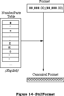 Figure 14–Str2Format
_______________________________________________________________________________
»Format2Str
In Pascal:
FUNCTION Format2Str(myCanonical: NumFormatString;partsTable: NumberParts;
VAR outString: Str255;
VAR positions: TripleInt): FormatStatus;
In C:
pascal FormatStatus Format2Str(const NumFormatString *myCanonical,
const NumberParts *partsTable,Str255 outString,TripleInt *positions);
Format2Str creates the string corresponding to a format definition string which has been created by a prior call to Str2Format and according to the NumberParts table. It is the inverse operation of Str2Format. This allows programs to display previously entered formats for users to edit.
Figure 14–Str2Format
_______________________________________________________________________________
»Format2Str
In Pascal:
FUNCTION Format2Str(myCanonical: NumFormatString;partsTable: NumberParts;
VAR outString: Str255;
VAR positions: TripleInt): FormatStatus;
In C:
pascal FormatStatus Format2Str(const NumFormatString *myCanonical,
const NumberParts *partsTable,Str255 outString,TripleInt *positions);
Format2Str creates the string corresponding to a format definition string which has been created by a prior call to Str2Format and according to the NumberParts table. It is the inverse operation of Str2Format. This allows programs to display previously entered formats for users to edit.
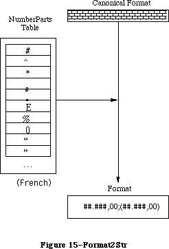 Figure 15–Format2Str
_______________________________________________________________________________
»FormatX2Str
In Pascal:
FUNCTION FormatX2Str(x: Extended;myCanonical: NumFormatString;
partsTable: NumberParts;
VAR outString: Str255): FormatStatus;
In C:
pascal FormatStatus FormatX2Str(extended x,const NumFormatString *myCanonical,
const NumberParts *partsTable,
Str255 outString);
This routine creates a textual representation of a number according to a canonical format which has been created by a prior call to Str2Format.
Figure 15–Format2Str
_______________________________________________________________________________
»FormatX2Str
In Pascal:
FUNCTION FormatX2Str(x: Extended;myCanonical: NumFormatString;
partsTable: NumberParts;
VAR outString: Str255): FormatStatus;
In C:
pascal FormatStatus FormatX2Str(extended x,const NumFormatString *myCanonical,
const NumberParts *partsTable,
Str255 outString);
This routine creates a textual representation of a number according to a canonical format which has been created by a prior call to Str2Format.
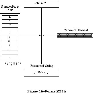 Figure 16–FormatX2Str
_______________________________________________________________________________
»FormatStr2X
In Pascal:
FUNCTION FormatStr2X(source: Str255;myCanonical: NumFormatString;
partsTable: NumberParts; VAR x: Extended): FormatStatus;
In C:
pascal FormatStatus FormatStr2X(const Str255 source,
const NumFormatString *myCanonical,
const NumberParts *partsTable,extended *x);
This routine reads a textual representation of a number according to a canonical format which has been created by a prior call to Str2Format, and creates an extended floating point number which corresponds to that string.
Internally, the routine converts the string into a format acceptable to SANE, matching against the three possible patterns in the canonical format. If the input string does not match any of the patterns, then FormatStr2X parses the string as best it can returning the result. Currently it is converted to a simple form, stripping non-digits and replacing the decimal point, before calling SANE.
Figure 16–FormatX2Str
_______________________________________________________________________________
»FormatStr2X
In Pascal:
FUNCTION FormatStr2X(source: Str255;myCanonical: NumFormatString;
partsTable: NumberParts; VAR x: Extended): FormatStatus;
In C:
pascal FormatStatus FormatStr2X(const Str255 source,
const NumFormatString *myCanonical,
const NumberParts *partsTable,extended *x);
This routine reads a textual representation of a number according to a canonical format which has been created by a prior call to Str2Format, and creates an extended floating point number which corresponds to that string.
Internally, the routine converts the string into a format acceptable to SANE, matching against the three possible patterns in the canonical format. If the input string does not match any of the patterns, then FormatStr2X parses the string as best it can returning the result. Currently it is converted to a simple form, stripping non-digits and replacing the decimal point, before calling SANE.
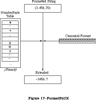 Figure 17–FormatStr2X
_______________________________________________________________________________
»HINTS FOR USING THE SCRIPT MANAGER
_______________________________________________________________________________
This section contains two programming suggestions you may find useful when using the Script Manager.
Note: In a work of this scope it is impossible to cover all aspects of script
manipulation. It is strongly advised that you obtain the latest version
of the Script Manager Developer’s Package before trying to write an
application that uses the Script Manager. This documentation is
available through the APDA.
_______________________________________________________________________________
»Testing for the Script Manager
Verify that the Script Manager is installed by checking to see if the Script Manager trap is implemented. To identify the number of scripts currently enabled, use the verb smEnabled. There is always at least one enabled script—Roman. Programs can use this information to optimize performance for the Roman version:
{ Globals }
Const
UnimplCoreRoutine = $9F; {unimplemented core routine}
ScriptUtil = $B5; {the Script Manager trap}
Var
scriptsInstalled : Integer; {global for testing throughout }
{ application}
.
.
.
{ Initialization: find out whether we can use the Script Manager }
scriptsInstalled := 0;
if GetTrapAddress(UnimplCoreRoutine) <> GetTrapAddress(ScriptUtil)
then scriptsInstalled := GetEnvirons(smEnabled);
.
.
.
{ Code: we can then bracket sections of the code that use the }
{ Script Manager }
if scriptsInstalled > 1
then begin
{use CharByte}
end else begin
{don’t use CharByte}
end;
Most script systems other than Roman will not install themselves on 64K ROMs, but the Roman interface system and utility routines will always be present if the Script Manager is installed.
_______________________________________________________________________________
»Setting the Keyboard Script
When the user selects a font from a menu, or clicks in text of a different script, the application should set the keyboard script. Key Caps Version 2.0 does this, for example. Use the following code:
{ Set the font for the item or port to myFont }
{ Set the keyboard to agree with the current script, if different}
if scriptsInstalled > 1 then begin {only if 2+ }
{ scripts}
if myFont <> oldFont then begin {quick check for }
{ speed}
newScript := Font2Script(myFont); {find the }
{ script}
if newScript <> oldScript then begin {if different}
if multiFont or { always switch }
{ mixed fonts}
(GetEnvirons(smKeyScript) <> smRoman) {don't }
{ switch if not}
then KeyScript(newScript); {switch the }
{ keyboard}
oldScript := newScript; {save global}
end;
oldFont := myFont; {save global}
end;
end;
Roman script is a special case with single-script text. Non-Roman scripts typically include the 128 ASCII characters, and users will alternate between the Roman keyboard and the native keyboard. Hence the Roman keyboard should be left alone when switching. With mixed-script text this is not true, since users will be using a Roman font when they want Roman text. For this case, you do not need to test for Roman.
To get the current keyboard script, and the system or application font for that script, use the code:
{ For the system font }
if scriptsInstalled <= 1 then scriptFont := systemFont
{default to system font}
else scriptFont := GetScript(GetEnvirons(smKeyScript), smScriptSysFond);
{ For the application font }
if scriptsInstalled <= 1 then scriptFont := applFont
{default to application font}
else scriptFont := GetScript(GetEnvirons(smKeyScript), smScriptAppFond);
This code can be used if your application does not have an interface that lets users change fonts but still needs to provide for different scripts.
_______________________________________________________________________________
»SUMMARY OF THE SCRIPT MANAGER
_______________________________________________________________________________
Note: This summary only covers the original Script Manager routines. The
Script Manager 2.0 routines and constants are available in the MPW 3.0
and later interface files.
Constants
CONST
{ Values of thePort.font }
smRoman = 0; {normal ASCII alphabet}
smKanji = 1; {Japanese}
smChinese = 2; {Chinese}
smKorean = 3; {Korean}
smArabic = 4; {Arabic}
smHebrew = 5; {Hebrew}
smGreek = 6; {Greek}
smRussian = 7; {Cyrillic}
smReserved1 = 8; {reserved}
smDevanagari = 9; {Devanagari}
smGurmukhi = 10; {Gurmukhi}
smGujarati = 11; {Gujarati}
smOriya = 12; {Oriya}
smBengali = 13; {Bengali}
smTamil = 14; {Tamil}
smTelugu = 15; {Telugu}
smKannada = 16; {Kannada}
smMalayalam = 17; {Malayalam}
smSinhalese = 18; {Sinhalese}
smBurmese = 19; {Burmese}
smKhmer = 20; {Khmer}
smThai = 21; {Thai}
smLaotian = 22; {Laotian}
smGeorgian = 23; {Georgian}
smArmenian = 24; {Armenian}
smMaldivian = 25; {Maldivian}
smTibetan = 26; {Tibetan}
smMongolian = 27; {Mongolian}
smAmharic = 28; {Ethiopian}
smSlavic = 29; {non-Cyrillic Slavic}
smVietnamese = 30; {Vietnamese}
smSindhi = 31; {Sindhi}
smUninterp = 32; {uninterpreted symbols}
{ CharType character types }
smCharPunct = 0;
smCharAscii = 1;
smCharEuro = 7;
{ CharType character classes }
smPunctNormal = $0000;
smPunctNumber = $0100;
smPunctSymbol = $0200;
smPunctBlank = $0300;
{ CharType directions }
smCharLeft = $0000;
smCharRight = $2000;
{ CharType character case }
smCharLower = $0000;
smCharUpper = $4000;
{ CharType character size (1 or 2 byte) }
smChar1byte = $0000;
smChar2byte = $8000;
{ Transliterate targets }
smTransAscii = 0 {target is Roman script}
smTransNative = 1 {target is non-Roman script}
smTransLower = 16384 {target becomes lowercase}
smTransUpper = 32768 {target becomes uppercase}
smMaskAscii = 1 {convert only Roman script}
smMaskNative = 2 {convert only non-Roman script}
smMaskAll = –1 {convert all text}
{ GetScript verbs }
smScriptVersion 0 Software version
smScriptMunged 2 Script entry changed count
smScriptEnabled 4 Script enabled flag
smScriptRight 6 Right-to-left flag
smScriptJust 8 Justification flag
smScriptRedraw 10 Word redraw flag
smScriptSysFond 12 Preferred system font
smScriptAppFond 14 Preferred application font
smScriptNumber 16 Script 'itl0' ID, from dictionary
smScriptDate 18 Script 'itl1' ID, from dictionary
smScriptSort 20 Script 'itl2' ID, from dictionary
smScriptFlags 22 Script Flags Word
smScriptToken 24 'itl4' ID number
smScriptRsvd 26 Reserved
smScriptLang 28 Script’s language code
smScriptNumDate 30 Number/Date Representation codes
smScriptKeys 32 Script 'KCHR' ID, from dictionary
smScriptIcon 34 Script 'SICN' ID, from dictionary
smScriptPrint 36 Script printer action routine
smScriptTrap 38 Trap entry pointer
smScriptCreator 40 Script file creator
smScriptFile 42 Script file name
smScriptName 44 Script name
{ GetEnvirons verbs }
smVersion 0 Environment version
smMunged 2 Globals changed count
smEnabled 4 Environment enabled flag
smBiDirect 6 Set if scripts of different directions
are installed together
smFontForce 8 Force font flag
smIntlForce 10 Force international utilities flag
smForced 12 Current script forced to system script
smDefault 14 Current script defaulted to Roman script
smPrint 16 Printer action routine
smSysScript 18 System script
smLastScript 20 Last keyboard script
smKeyScript 22 Keyboard script
smSysRef 24 System folder reference number
smKeyCache 26 Keyboard table cache pointer
smKeySwap 28 Swapping table pointer
smGenFlags 30 General Flags
smOverride 32 Script Override flags
smCharPortion 34 Ch vs Sp Extra proportion, 4.12 fixed
_______________________________________________________________________________
Routines
Script Information Routines
FUNCTION FontScript : Integer;
FUNCTION IntlScript : Integer;
PROCEDURE KeyScript (scriptCode: Integer);
Character Information Routines
FUNCTION CharByte (textBuf: Ptr; textOffset: Integer) : Integer;
FUNCTION CharType (textBuf: Ptr; textOffset: Integer) : Integer;
Text Editing Routines
FUNCTION Pixel2Char (textBuf: Ptr; textLen, slop,pixelWidth: Integer ;
VAR leftSide: Boolean): Integer;
FUNCTION Char2Pixel (textBuf: Ptr; textLen, slop,offset: Integer;
direction: SignedByte) : Integer;
PROCEDURE FindWord (textPtr: Ptr; textLength, offset: Integer;
leftSide: Boolean; breaks: BreakTable;
var offsets: OffsetTable);
PROCEDURE HiliteText (textPtr: Ptr;
textLength, firstOffset, secondOffset: Integer;
VAR offsets: OffsetTable);
PROCEDURE DrawJust (textPtr: Ptr; textLength, slop: Integer);
PROCEDURE MeasureJust (textPtr: Ptr; textLength, slop: Integer; charLocs: Ptr);
Advanced Routines
FUNCTION Transliterate (srcHandle, dstHandle: Handle;
target: Integer; srcMask: Longint) : Integer;
FUNCTION Font2Script (fontNumber: Integer) : Integer;
System Routines
FUNCTION GetScript (script, verb: Integer) : LongInt;
FUNCTION SetScript (script, verb: Integer; param: LongInt) : OSErr;
FUNCTION GetEnvirons (verb: Integer) : LongInt;
FUNCTION SetEnvirons (verb: Integer; param: LongInt) : OSErr;
FUNCTION GetDefFontSize: Integer;
FUNCTION GetSysFont: Integer;
FUNCTION GetAppFont: Integer;
FUNCTION GetMBarHeight: Integer;
FUNCTION GetSysJust: Integer;
PROCEDURE SetSysJust (newJust: Integer);
_______________________________________________________________________________
Assembly-Language Information
Constants
; Routine selectors for _ScriptUtil trap
smFontScript EQU 0
smIntlScript EQU 2
smKybdScript EQU 4
smFont2Script EQU 6
smGetEnvirons EQU 8
smSetEnvirons EQU 10
smGetScript EQU 12
smSetScript EQU 14
smCharByte EQU 16
smCharType EQU 18
smPixel2Char EQU 20
smChar2Pixel EQU 22
smTranslit EQU 24
smFindWord EQU 26
smHiliteText EQU 28
smDrawJust EQU 30
smMeasureJust EQU 32
Trap Macro Name
_ScriptUtil
Note: You can invoke each of the Script Manager routines with a macro that
has the same name as the routine preceded by an underscore.
Further Reference:
_______________________________________________________________________________
QuickDraw
International Utilities
Binary-Decimal Conv Pkg
Font Manager
TextEdit
Technical Note #153, Changes in International Utilities and Resources
Technical Note #160, Key Mapping
Technical Note #174, Accessing the Script Manager Print Action Routine
Technical Note #182, How to Construct Word-Break Tables
Technical Note #241, Script Manager’s Pixel2Char Routine
Technical Note #242, Fonts and the Script Manager
Technical Note #243, Script Manager Variables
Figure 17–FormatStr2X
_______________________________________________________________________________
»HINTS FOR USING THE SCRIPT MANAGER
_______________________________________________________________________________
This section contains two programming suggestions you may find useful when using the Script Manager.
Note: In a work of this scope it is impossible to cover all aspects of script
manipulation. It is strongly advised that you obtain the latest version
of the Script Manager Developer’s Package before trying to write an
application that uses the Script Manager. This documentation is
available through the APDA.
_______________________________________________________________________________
»Testing for the Script Manager
Verify that the Script Manager is installed by checking to see if the Script Manager trap is implemented. To identify the number of scripts currently enabled, use the verb smEnabled. There is always at least one enabled script—Roman. Programs can use this information to optimize performance for the Roman version:
{ Globals }
Const
UnimplCoreRoutine = $9F; {unimplemented core routine}
ScriptUtil = $B5; {the Script Manager trap}
Var
scriptsInstalled : Integer; {global for testing throughout }
{ application}
.
.
.
{ Initialization: find out whether we can use the Script Manager }
scriptsInstalled := 0;
if GetTrapAddress(UnimplCoreRoutine) <> GetTrapAddress(ScriptUtil)
then scriptsInstalled := GetEnvirons(smEnabled);
.
.
.
{ Code: we can then bracket sections of the code that use the }
{ Script Manager }
if scriptsInstalled > 1
then begin
{use CharByte}
end else begin
{don’t use CharByte}
end;
Most script systems other than Roman will not install themselves on 64K ROMs, but the Roman interface system and utility routines will always be present if the Script Manager is installed.
_______________________________________________________________________________
»Setting the Keyboard Script
When the user selects a font from a menu, or clicks in text of a different script, the application should set the keyboard script. Key Caps Version 2.0 does this, for example. Use the following code:
{ Set the font for the item or port to myFont }
{ Set the keyboard to agree with the current script, if different}
if scriptsInstalled > 1 then begin {only if 2+ }
{ scripts}
if myFont <> oldFont then begin {quick check for }
{ speed}
newScript := Font2Script(myFont); {find the }
{ script}
if newScript <> oldScript then begin {if different}
if multiFont or { always switch }
{ mixed fonts}
(GetEnvirons(smKeyScript) <> smRoman) {don't }
{ switch if not}
then KeyScript(newScript); {switch the }
{ keyboard}
oldScript := newScript; {save global}
end;
oldFont := myFont; {save global}
end;
end;
Roman script is a special case with single-script text. Non-Roman scripts typically include the 128 ASCII characters, and users will alternate between the Roman keyboard and the native keyboard. Hence the Roman keyboard should be left alone when switching. With mixed-script text this is not true, since users will be using a Roman font when they want Roman text. For this case, you do not need to test for Roman.
To get the current keyboard script, and the system or application font for that script, use the code:
{ For the system font }
if scriptsInstalled <= 1 then scriptFont := systemFont
{default to system font}
else scriptFont := GetScript(GetEnvirons(smKeyScript), smScriptSysFond);
{ For the application font }
if scriptsInstalled <= 1 then scriptFont := applFont
{default to application font}
else scriptFont := GetScript(GetEnvirons(smKeyScript), smScriptAppFond);
This code can be used if your application does not have an interface that lets users change fonts but still needs to provide for different scripts.
_______________________________________________________________________________
»SUMMARY OF THE SCRIPT MANAGER
_______________________________________________________________________________
Note: This summary only covers the original Script Manager routines. The
Script Manager 2.0 routines and constants are available in the MPW 3.0
and later interface files.
Constants
CONST
{ Values of thePort.font }
smRoman = 0; {normal ASCII alphabet}
smKanji = 1; {Japanese}
smChinese = 2; {Chinese}
smKorean = 3; {Korean}
smArabic = 4; {Arabic}
smHebrew = 5; {Hebrew}
smGreek = 6; {Greek}
smRussian = 7; {Cyrillic}
smReserved1 = 8; {reserved}
smDevanagari = 9; {Devanagari}
smGurmukhi = 10; {Gurmukhi}
smGujarati = 11; {Gujarati}
smOriya = 12; {Oriya}
smBengali = 13; {Bengali}
smTamil = 14; {Tamil}
smTelugu = 15; {Telugu}
smKannada = 16; {Kannada}
smMalayalam = 17; {Malayalam}
smSinhalese = 18; {Sinhalese}
smBurmese = 19; {Burmese}
smKhmer = 20; {Khmer}
smThai = 21; {Thai}
smLaotian = 22; {Laotian}
smGeorgian = 23; {Georgian}
smArmenian = 24; {Armenian}
smMaldivian = 25; {Maldivian}
smTibetan = 26; {Tibetan}
smMongolian = 27; {Mongolian}
smAmharic = 28; {Ethiopian}
smSlavic = 29; {non-Cyrillic Slavic}
smVietnamese = 30; {Vietnamese}
smSindhi = 31; {Sindhi}
smUninterp = 32; {uninterpreted symbols}
{ CharType character types }
smCharPunct = 0;
smCharAscii = 1;
smCharEuro = 7;
{ CharType character classes }
smPunctNormal = $0000;
smPunctNumber = $0100;
smPunctSymbol = $0200;
smPunctBlank = $0300;
{ CharType directions }
smCharLeft = $0000;
smCharRight = $2000;
{ CharType character case }
smCharLower = $0000;
smCharUpper = $4000;
{ CharType character size (1 or 2 byte) }
smChar1byte = $0000;
smChar2byte = $8000;
{ Transliterate targets }
smTransAscii = 0 {target is Roman script}
smTransNative = 1 {target is non-Roman script}
smTransLower = 16384 {target becomes lowercase}
smTransUpper = 32768 {target becomes uppercase}
smMaskAscii = 1 {convert only Roman script}
smMaskNative = 2 {convert only non-Roman script}
smMaskAll = –1 {convert all text}
{ GetScript verbs }
smScriptVersion 0 Software version
smScriptMunged 2 Script entry changed count
smScriptEnabled 4 Script enabled flag
smScriptRight 6 Right-to-left flag
smScriptJust 8 Justification flag
smScriptRedraw 10 Word redraw flag
smScriptSysFond 12 Preferred system font
smScriptAppFond 14 Preferred application font
smScriptNumber 16 Script 'itl0' ID, from dictionary
smScriptDate 18 Script 'itl1' ID, from dictionary
smScriptSort 20 Script 'itl2' ID, from dictionary
smScriptFlags 22 Script Flags Word
smScriptToken 24 'itl4' ID number
smScriptRsvd 26 Reserved
smScriptLang 28 Script’s language code
smScriptNumDate 30 Number/Date Representation codes
smScriptKeys 32 Script 'KCHR' ID, from dictionary
smScriptIcon 34 Script 'SICN' ID, from dictionary
smScriptPrint 36 Script printer action routine
smScriptTrap 38 Trap entry pointer
smScriptCreator 40 Script file creator
smScriptFile 42 Script file name
smScriptName 44 Script name
{ GetEnvirons verbs }
smVersion 0 Environment version
smMunged 2 Globals changed count
smEnabled 4 Environment enabled flag
smBiDirect 6 Set if scripts of different directions
are installed together
smFontForce 8 Force font flag
smIntlForce 10 Force international utilities flag
smForced 12 Current script forced to system script
smDefault 14 Current script defaulted to Roman script
smPrint 16 Printer action routine
smSysScript 18 System script
smLastScript 20 Last keyboard script
smKeyScript 22 Keyboard script
smSysRef 24 System folder reference number
smKeyCache 26 Keyboard table cache pointer
smKeySwap 28 Swapping table pointer
smGenFlags 30 General Flags
smOverride 32 Script Override flags
smCharPortion 34 Ch vs Sp Extra proportion, 4.12 fixed
_______________________________________________________________________________
Routines
Script Information Routines
FUNCTION FontScript : Integer;
FUNCTION IntlScript : Integer;
PROCEDURE KeyScript (scriptCode: Integer);
Character Information Routines
FUNCTION CharByte (textBuf: Ptr; textOffset: Integer) : Integer;
FUNCTION CharType (textBuf: Ptr; textOffset: Integer) : Integer;
Text Editing Routines
FUNCTION Pixel2Char (textBuf: Ptr; textLen, slop,pixelWidth: Integer ;
VAR leftSide: Boolean): Integer;
FUNCTION Char2Pixel (textBuf: Ptr; textLen, slop,offset: Integer;
direction: SignedByte) : Integer;
PROCEDURE FindWord (textPtr: Ptr; textLength, offset: Integer;
leftSide: Boolean; breaks: BreakTable;
var offsets: OffsetTable);
PROCEDURE HiliteText (textPtr: Ptr;
textLength, firstOffset, secondOffset: Integer;
VAR offsets: OffsetTable);
PROCEDURE DrawJust (textPtr: Ptr; textLength, slop: Integer);
PROCEDURE MeasureJust (textPtr: Ptr; textLength, slop: Integer; charLocs: Ptr);
Advanced Routines
FUNCTION Transliterate (srcHandle, dstHandle: Handle;
target: Integer; srcMask: Longint) : Integer;
FUNCTION Font2Script (fontNumber: Integer) : Integer;
System Routines
FUNCTION GetScript (script, verb: Integer) : LongInt;
FUNCTION SetScript (script, verb: Integer; param: LongInt) : OSErr;
FUNCTION GetEnvirons (verb: Integer) : LongInt;
FUNCTION SetEnvirons (verb: Integer; param: LongInt) : OSErr;
FUNCTION GetDefFontSize: Integer;
FUNCTION GetSysFont: Integer;
FUNCTION GetAppFont: Integer;
FUNCTION GetMBarHeight: Integer;
FUNCTION GetSysJust: Integer;
PROCEDURE SetSysJust (newJust: Integer);
_______________________________________________________________________________
Assembly-Language Information
Constants
; Routine selectors for _ScriptUtil trap
smFontScript EQU 0
smIntlScript EQU 2
smKybdScript EQU 4
smFont2Script EQU 6
smGetEnvirons EQU 8
smSetEnvirons EQU 10
smGetScript EQU 12
smSetScript EQU 14
smCharByte EQU 16
smCharType EQU 18
smPixel2Char EQU 20
smChar2Pixel EQU 22
smTranslit EQU 24
smFindWord EQU 26
smHiliteText EQU 28
smDrawJust EQU 30
smMeasureJust EQU 32
Trap Macro Name
_ScriptUtil
Note: You can invoke each of the Script Manager routines with a macro that
has the same name as the routine preceded by an underscore.
Further Reference:
_______________________________________________________________________________
QuickDraw
International Utilities
Binary-Decimal Conv Pkg
Font Manager
TextEdit
Technical Note #153, Changes in International Utilities and Resources
Technical Note #160, Key Mapping
Technical Note #174, Accessing the Script Manager Print Action Routine
Technical Note #182, How to Construct Word-Break Tables
Technical Note #241, Script Manager’s Pixel2Char Routine
Technical Note #242, Fonts and the Script Manager
Technical Note #243, Script Manager Variables
The SCSI Manager
_______________________________________________________________________________
THE SCSI MANAGER
_______________________________________________________________________________
About This Chapter
About the SCSI Manager
Using the SCSI Manager
Describing the Operation to be Performed
Example
SCSI Manager Routines
Transfer Modes
Writing a Driver for a SCSI Block Device
Disk Partitioning
Driver Descriptor Map
Partition Map
Partitioning Guidelines
Summary of the SCSI Manager
_______________________________________________________________________________
»ABOUT THIS CHAPTER
_______________________________________________________________________________
This chapter describes the SCSI Manager, the part of the Operating System that controls the exchange of information between a Macintosh and peripheral devices connected through the Small Computer Standard Interface (SCSI).
The SCSI Manager is the Macintosh implementation of an SCSI bus and its attached devices. This chapter describes the routines and data structures
you’ll use to communicate between a Macintosh and peripherals over an SCSI bus. It also explains how to write an SCSI device driver that’s capable of performing the Macintosh system startup.
This chapter provides information needed to connect a device to the Macintosh via an SCSI bus; it is not intended as a guide to designing an SCSI device. A familiarity with the American National Standard Committee (ANSC) documentation for SCSI, specifically the ANSC X3T9.2/82-2 draft proposal, is assumed; the information provided in the draft proposal will not be repeated in this chapter.
You should also already be familiar with:
• the use of devices and device drivers, as described in the
Device Manager chapter
• sectors and file tags, as described in the Disk Driver chapter
• any documentation provided with the particular SCSI device you want to
connect to the Macintosh
_______________________________________________________________________________
»ABOUT THE SCSI MANAGER
_______________________________________________________________________________
The Small Computer Standard Interface (SCSI) is a specification of mechanical, electrical, and functional standards for connecting small computers with intelligent peripherals such as hard disks, printers, and optical disks. The SCSI Manager is the part of the Operating System that provides routines and data structures for communicating between a Macintosh and peripheral devices according to this industry-standard interface.
Up to eight devices can be connected, in a daisy-chain configuration, to an SCSI bus. When two SCSI devices communicate with each other, one acts as the initiator and the other as the target. The initiator asks the target to perform a certain operation, such as reading a block of data. An SCSI device typically has a fixed role as an initiator or target; for instance, the Macintosh acts as initiator to a variety of peripherals acting as targets. There may also be intelligent peripherals capable of acting as initiators. Multiple initiators
(as well as multiple targets) are allowed on an SCSI bus, but only one Macintosh can be connected to an SCSI bus at a time.
Each device on the bus has a unique ID, an integer from 0 to 7. The Macintosh always has an ID of 7; peripheral devices should choose another number.
At any given time, the Apple SCSI bus is in one of eight phases. When no SCSI device is actively using the bus, the bus is in the bus free phase.
Since multiple initiators are possible, an initiator must first gain control of the bus; this process is called the arbitration phase.
Note: If more than one initiator arbitrates for use of the bus at the same
time, the initiator with the higher ID gains control first. Once an
initiator (regardless of ID) gains control of the bus, no other device
can interrupt that session.
Once the initiator has gained control of the bus, it selects the target device that will be asked to perform a certain operation; this phase, known as the selection phase, includes an acknowledgement from the target that it has been selected. In the event that the target suspends (or disconnects) the communication, an optional phase, known as the reselection phase, lets the target reconnect to the initiator.
In the command phase, the initiator tells the target what operation to perform. The data phase follows; this is when the actual transfer of data between initiator and target takes place. When the operation is completed, the target sends two completion bytes. The first byte contains status information and the second contains a message; they constitute the status phase and message phase respectively.
A typical communication might involve a Macintosh requesting a block of data to be read from a hard disk connected via an SCSI bus. The Macintosh waits for a bus free phase to occur and then arbitrates for use of the bus. It selects the hard disk as target and sends the command for the read operation. The hard disk transfers the requested data back to the Macintosh, completing the session by sending the status and message bytes.
On the Macintosh SE and Macintosh II, the SCSIRBlind and SCSIWBlind functions have hardware support; this ensures that they will work reliably with most third-party SCSI drives.
Warning: SCSI drivers that jump directly to the ROM will crash on any machine
other than a Macintosh Plus.
_______________________________________________________________________________
»USING THE SCSI MANAGER
_______________________________________________________________________________
The SCSI Manager is automatically initialized when the system starts up. To gain control of the SCSI bus, call SCSIGet. To select a target device to perform an operation (such as reading or writing data), call SCSISelect. The SCSICmd function tells the target device what operation to perform.
To transfer data from the target device to the Macintosh, you can call SCSIRead; SCSIWrite transfers data from the Macintosh to the target device. The read and write operations can be performed without polling and waiting for the /REQ line on each data byte by calling SCSIRBlind and SCSIWBlind, respectively. All four read/write functions require a transfer instruction block telling the SCSI Manager what to do with the data bytes transferred during the data phase.
The SCSIComplete function gives the current command a specified number of ticks to complete and then returns the status and message bytes.
You can obtain a bit map of the SCSI control and status bits by calling SCSIStat. To reset the SCSI bus (typically when a device has left it in a suspended phase), call SCSIReset.
Three new routines support the message phase of the SCSI standard. SCSISelAtn lets you select a device, alerting the device that you want to send a message. SCSIMsgOut sends a message byte to the device, and SCSIMsgIn receives a message byte from the device.
_______________________________________________________________________________
»Describing the Operation to be Performed
You tell the SCSI Manager what operation to perform by passing a pointer to a command descriptor block; the SCSI command structure is outlined in the ANSC document X3T9.2/82-2.
When the command to be performed involves a transfer of data (such as a read or write operation), you also need to pass a pointer to a transfer instruction block, which tells the SCSI Manager what to do with the data bytes transferred during the data phase. A transfer instruction block contains a pseudo-program consisting of a variable number of instructions; it’s similar to a subroutine except that the instructions are provided and interpreted by the SCSI Manager itself. The instructions are of a fixed size and have the following structure:
TYPE SCSIInstr = RECORD
scOpcode: INTEGER; {operation code}
scParam1: LONGINT; {first parameter}
scParam2: LONGINT {second parameter}
END;
Eight instructions are available; their operation codes are specified with the following predefined constants:
CONST scInc = 1; {SCINC instruction}
scNoInc = 2; {SCNOINC instruction}
scAdd = 3; {SCADD instruction}
scMove = 4; {SCMOVE instruction}
scLoop = 5; {SCLOOP instruction}
scNOp = 6; {SCNOP instruction}
scStop = 7; {SCSTOP instruction}
scComp = 8; {SCCOMP instruction}
A description of the instructions is given below.
opcode = scInc param1 = buffer param2 = count
The SCINC instruction moves count data bytes to or from buffer, incrementing buffer by count when done.
opcode = scNoInc param1 = buffer param2 = count
The SCNOINC instruction moves count data bytes to or from buffer, leaving buffer unmodified.
opcode = scAdd param1 = addr param2 = value
The SCADD instruction adds the given value to the address in addr. (The addition is performed as an MC68000 long operation.)
opcode = scMove param1 = addr1 param2 = addr2
The SCMOVE instruction moves the value pointed at by addr1 to the location pointed to by addr2. (The move is an MC68000 long operation.)
opcode = scLoop param1 = relAddr param2 = count
The SCLOOP instruction decrements count by 1. If the result is greater than 0, pseudo-program execution resumes at the current address+relAddr. If the result is 0, pseudo-program execution resumes at the next instruction. RelAddr should be a signed multiple of the instruction size (10 bytes). For example, to loop to the immediately preceding instruction, the relAddr field would contain –10. To loop forward by three instructions, it would contain 30.
opcode = scNOp param1 = NIL param2 = NIL
The SCNOP instruction does nothing.
opcode = scStop param1 = NIL param2 = NIL
The SCSTOP instruction terminates the pseudo-program execution, returning to the calling SCSI Manager routine.
opcode = scComp param1 = addr param2 = count
The SCCOMP instruction is used only with a read command. Beginning at addr, it compares incoming data bytes with memory, incrementing addr by count when done. If the bytes do not compare equally, an error is returned to the read command.
»Example
This example gives a transfer instruction block for a transfer of six 512-byte blocks of data from or to address $67B50.
SCINC $67B50 512
SCLOOP -10 6
SCSTOP
_______________________________________________________________________________
»SCSI MANAGER ROUTINES
_______________________________________________________________________________
Assembly-language note: Unlike most other Operating System routines, the SCSI
Manager routines are stack-based. You can invoke each
of the SCSI routines with a macro that has the same
name as the routine preceded by an underscore. These
macros, however, aren’t trap macros themselves;
instead they expand to invoke the trap macro
_SCSIDispatch. The SCSI Manager determines which
routine to execute from the routine selector, an
integer that’s passed to it in a word on the stack.
The routine selectors for the new routines are as
follows:
scsiReset .EQU 0
scsiGet .EQU 1
scsiSelect .EQU 2
scsiCmd .EQU 3
scsiComplete .EQU 4
scsiRead .EQU 5
scsiWrite .EQU 6
scsiRBlind .EQU 8
scsiWBlind .EQU 9
scsiStat .EQU 10
scsiSelAtn .EQU 11
scsiMsgIn .EQU 12
scsiMsgOut .EQU 13
If you specify a routine selector that’s not defined, the System Error Handler is called with the system error ID dsCoreErr.
Most of the SCSI Manager routines return an integer result code of type OSErr. Each routine lists all of the applicable result codes, along with a short description of what the result code means. Lengthier explanations of all the result codes can be found in the summary at the end of this chapter. The error scSequenceErr is not listed under each operation. It is returned when an attempted operation is out of sequence (calling SCSISelect without first calling SCSIGet, for instance).
Warning: The error codes returned by SCSI Manager routines typically indicate
only that a given operation failed. To determine the actual cause of
the failure, you need to send another SCSI command asking the device
what went wrong.
FUNCTION SCSIReset : OSErr;
SCSIReset resets the SCSI bus.
Result codes noErr No error
commErr Breakdown in SCSI protocols
FUNCTION SCSIGet : OSErr;
SCSIGet arbitrates for use of the SCSI bus.
Result codes noErr No error
commErr Breakdown in SCSI protocols
scArbNBErr Bus is busy
scMgrBusyErr SCSI Manager busy with another operation
FUNCTION SCSISelect (targetID: INTEGER) : OSErr;
SCSISelect selects the device whose ID is in targetID.
Result codes noErr No error
commErr Breakdown in SCSI protocols
FUNCTION SCSICmd (buffer: Ptr; count: INTEGER) : OSErr;
SCSICmd sends the command pointed to by buffer to the selected target device. The size of the command in bytes is specified in count.
Result codes noErr No error
commErr Breakdown in SCSI protocols
phaseErr Phase error
FUNCTION SCSIRead (tibPtr: Ptr) : OSErr;
SCSIRead transfers data from the target to the initiator, as specified in the transfer instruction block pointed to by tibPtr.
Result codes noErr No error
badParmsErr Unrecognized instruction in transfer instruction
block
commErr Breakdown in SCSI protocols
compareErr Data comparison error (with scComp command
in transfer instruction block)
phaseErr Phase error
FUNCTION SCSIRBlind (tibPtr: Ptr) : OSErr;
SCSIRBlind is functionally identical to SCSIRead, but does not poll and wait for the /REQ line on each data byte. Rather, the /REQ line is polled only for the first byte transferred by each SCINC, SCNOINC, or SCCOMP instruction. For instance, given the following transfer instruction block
SCINC $67B50 512
SCLOOP -10 6
SCSTOP
SCSIRBlind polls and waits only for the first byte of each 512-byte block transferred.
Result codes noErr No error
badParmsErr Unrecognized instruction
commErr Breakdown in SCSI protocols
compareErr Data comparison error
phaseErr Phase error
scBusTOErr Data not ready within the bus timeout period
FUNCTION SCSIWrite (tibPtr: Ptr) : OSErr;
SCSIWrite transfers data from the initiator to the target, as specified in the command descriptor block pointed to by tibPtr.
Result codes noErr No error
badParmsErr Unrecognized instruction
commErr Breakdown in SCSI protocols
phaseErr Phase error
FUNCTION SCSIWBlind (tibPtr: Ptr) : OSErr;
SCSIWBlind is functionally identical to SCSIWrite, but does not poll and wait for the /REQ line on each data byte. As with SCSIRBlind, SCSIWBlind polls the
/REQ line only for the first byte transferred by each SCINC, SCNOINC, or SCCOMP instruction.
Result codes noErr No error
badParmsErr Unrecognized instruction
commErr Breakdown in SCSI protocols
phaseErr Phase error
scBusTOErr Data not ready within the bus timeout period
FUNCTION SCSIComplete (VAR stat,message: INTEGER; wait: LONGINT) : OSErr;
SCSIComplete gives the current command wait number of ticks to complete; the two completion bytes are returned in stat and message.
Result codes noErr No error
commErr Breakdown in SCSI protocols
phaseErr Phase error
scComplPhaseErr Bus not in the Status phase (indicates
that either filler bytes were written or
bytes were read and lost)
FUNCTION SCSIStat : INTEGER;
This function returns a bit map of SCSI control and status bits; these bits are shown in Figure 1. See the NCR 5380 SCSI chip documentation for a description of these signals. (Bits 0–9 are complements of the SCSI bus standard signals.)
Result codes noErr No error
commErr Breakdown in SCSI protocols
phaseErr Phase error
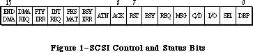 Figure 1–SCSI Control and Status Bits
FUNCTION SCSISelAtn (targetID: INTEGER) : OSErr;
SCSISelAtn is identical in function to SCSISelect except that it asserts the Attention line during selection, signaling that you want to send a message to the device.
FUNCTION SCSIMsgIn (VAR message: INTEGER) : OSErr;
SCSIMsgIn gets a message from the device. The message is contained in the low-order byte of the message parameter; message values are listed in the ANSI documentation for SCSI.
SCSIMsgIn leaves the Attention line undisturbed if it’s already asserted upon entry.
FUNCTION SCSIMsgOut (message: INTEGER) : OSErr;
SCSIMsgOut sends a message byte to the target device; message values are listed in the ANSI documentation for SCSI.
_______________________________________________________________________________
»TRANSFER MODES
_______________________________________________________________________________
The Macintosh Plus SCSI Manager implements two transfer modes: polled and blind. The polled mode checks the DRQ signal on the 5380 SCSI chip before each byte is transferred (on both read and write operations). While slower than blind mode, the polled mode is completely safe since the SCSI Manager will wait indefinitely for each byte sent to or from the peripheral.
The blind mode does not poll the DRQ line and is therefore about 50% faster. Use of this mode imposes certain timing constraints, however, making it unreliable for some peripherals. Once a transfer is underway, if the peripheral’s controller cannot send (or receive) a byte every 2 microseconds, the SCSI Manager may either read invalid data or write data faster than the peripheral can accept it, resulting in the loss of data.
Programmers writing SCSI device drivers must be familiar with the limits of their peripherals. If the peripheral has internal interrupts, for instance, or if it has processing overhead at unpredictable points within a block transfer, the blind mode should not be used.
Note: If the peripheral has a regular pause at a specific byte number within
a block, it’s possible to use a transfer information block containing
two or more data transfer pseudoinstructions. Since the SCSI Manager
will handshake the first byte at the beginning of each data transfer
operation, this can be used to synchronize with the peripheral’s
internal processing.
The Macintosh SE and Macintosh II have additional hardware support for SCSI data transfers. For compatibility, the faster transfer routines are still called SCSIRBlind and SCSIWBlind; these routines do, however, take advantage of the hardware handshaking available on the new machines. Use of the hardware handshake, however, imposes other timing constraints. If the time between any two bytes in a data transfer exceeds a certain period—between 265 and 284 milliseconds on the Macintosh SE and approximately 16 microseconds on the Macintosh II—a CPU bus error is generated. If your peripheral cannot meet this constraint, you should use the polled mode calls, SCSIRead and SCSIWrite.
_______________________________________________________________________________
»WRITING A DRIVER FOR A SCSI BLOCK DEVICE
_______________________________________________________________________________
Device drivers are usually written in assembly language. The structure of a device driver is described in the Device Manager chapter. This section presents additional information to enable SCSI block devices to perform the Macintosh system startup.
For each attached SCSI device, the ROM attempts to read in its driver prior to system startup. In order to be loaded, the device must place two data structures in the first two physical blocks. A driver descriptor map must be put at the start of physical block 0; it identifies the various device drivers available for loading (see Figure 2). The drivers can then be located anywhere else on the device and can be as large as necessary.
Figure 1–SCSI Control and Status Bits
FUNCTION SCSISelAtn (targetID: INTEGER) : OSErr;
SCSISelAtn is identical in function to SCSISelect except that it asserts the Attention line during selection, signaling that you want to send a message to the device.
FUNCTION SCSIMsgIn (VAR message: INTEGER) : OSErr;
SCSIMsgIn gets a message from the device. The message is contained in the low-order byte of the message parameter; message values are listed in the ANSI documentation for SCSI.
SCSIMsgIn leaves the Attention line undisturbed if it’s already asserted upon entry.
FUNCTION SCSIMsgOut (message: INTEGER) : OSErr;
SCSIMsgOut sends a message byte to the target device; message values are listed in the ANSI documentation for SCSI.
_______________________________________________________________________________
»TRANSFER MODES
_______________________________________________________________________________
The Macintosh Plus SCSI Manager implements two transfer modes: polled and blind. The polled mode checks the DRQ signal on the 5380 SCSI chip before each byte is transferred (on both read and write operations). While slower than blind mode, the polled mode is completely safe since the SCSI Manager will wait indefinitely for each byte sent to or from the peripheral.
The blind mode does not poll the DRQ line and is therefore about 50% faster. Use of this mode imposes certain timing constraints, however, making it unreliable for some peripherals. Once a transfer is underway, if the peripheral’s controller cannot send (or receive) a byte every 2 microseconds, the SCSI Manager may either read invalid data or write data faster than the peripheral can accept it, resulting in the loss of data.
Programmers writing SCSI device drivers must be familiar with the limits of their peripherals. If the peripheral has internal interrupts, for instance, or if it has processing overhead at unpredictable points within a block transfer, the blind mode should not be used.
Note: If the peripheral has a regular pause at a specific byte number within
a block, it’s possible to use a transfer information block containing
two or more data transfer pseudoinstructions. Since the SCSI Manager
will handshake the first byte at the beginning of each data transfer
operation, this can be used to synchronize with the peripheral’s
internal processing.
The Macintosh SE and Macintosh II have additional hardware support for SCSI data transfers. For compatibility, the faster transfer routines are still called SCSIRBlind and SCSIWBlind; these routines do, however, take advantage of the hardware handshaking available on the new machines. Use of the hardware handshake, however, imposes other timing constraints. If the time between any two bytes in a data transfer exceeds a certain period—between 265 and 284 milliseconds on the Macintosh SE and approximately 16 microseconds on the Macintosh II—a CPU bus error is generated. If your peripheral cannot meet this constraint, you should use the polled mode calls, SCSIRead and SCSIWrite.
_______________________________________________________________________________
»WRITING A DRIVER FOR A SCSI BLOCK DEVICE
_______________________________________________________________________________
Device drivers are usually written in assembly language. The structure of a device driver is described in the Device Manager chapter. This section presents additional information to enable SCSI block devices to perform the Macintosh system startup.
For each attached SCSI device, the ROM attempts to read in its driver prior to system startup. In order to be loaded, the device must place two data structures in the first two physical blocks. A driver descriptor map must be put at the start of physical block 0; it identifies the various device drivers available for loading (see Figure 2). The drivers can then be located anywhere else on the device and can be as large as necessary.
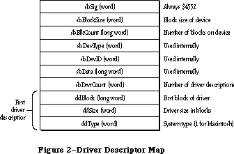 Figure 2–Driver Descriptor Map
A second data structure, the device partition map, must be put at the start of physical block 1; it describes the allocation of blocks on the device for different partitions and/or operating systems (see Figure 3).
Figure 2–Driver Descriptor Map
A second data structure, the device partition map, must be put at the start of physical block 1; it describes the allocation of blocks on the device for different partitions and/or operating systems (see Figure 3).
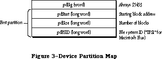 Figure 3–Device Partition Map
Since there’s no field in the device partition map for specifying the number of partitions, you need to signal the end of the map with a partition whose pdStart, pdSize, and pdFSID fields are set to 0.
The system startup procedure takes the following steps:
1. It attempts to select the first target device on the bus by its ID,
beginning with the device, if any, having an ID of 6.
2. It reads the first 256 bytes of physical block 0, checking for the
signature indicating a valid driver descriptor map ($4552). It then
reads the device partition map from physical block 1 and checks for
the proper signature ($504D). Note that old-style partition maps
have a signature of ($5453) instead of ($504D).
3. It searches the driver descriptor map for a driver for the Macintosh.
4. It reads the driver from the indicated physical blocks into the system
heap, using standard SCSI read commands. It checks for a proper driver
signature.
5. It calls the driver to install itself, and passes a pointer to the
device partition map for examination by the driver.
6. It performs steps 1 through 5 for all other SCSI devices on the bus.
Note: During system startup, the SCSI Manager may call SCSIReset after your
driver has been loaded.
Since the driver is called to install itself, it must contain code to set up its own entry in the unit table and to call its own Open routine. An example of how to do this can be obtained from
Developer Technical Support
Apple Computer, Inc.
20525 Mariani Avenue, M/S 75-3T
Cupertino, CA 95014
_______________________________________________________________________________
»DISK PARTITIONING
_______________________________________________________________________________
The previous section introduced the subject of booting from SCSI devices. It presents two data structures needed in the first two physical blocks of the device. The first data structure, the driver descriptor map, identifies the various device drivers available for loading. The second structure, the device partition map, presents a scheme for describing the allocation, or partitioning, of the blocks of a device between multiple operating systems.
In order to support multiple operating systems on a single disk, the device partition map has been redesigned. The old partition map format is still supported, but developers are encouraged to adopt the new format (see below).
_______________________________________________________________________________
»Driver Descriptor Map
A driver descriptor map must always be located at the start of physical block 0; its format is given in Figure 2.
SBSig contains the signature; it’s used to verify that the block is valid (that is, the disk has been formatted) and should always be $4552.
SBDrvrCount specifies the number of drivers that may be used for this disk; more than one driver may be needed when multiple operating systems or processors are supported.
There must be a driver descriptor for each driver on the device (as well as a partition map entry, as explained below). DDBlock is the address of the first physical block of the driver code. DDSize contains the size of the driver in blocks. DDType identifies the operating system or processor supported by the driver. The Macintosh Operating System has the value 1; values 0 through 15 are reserved for use by Apple.
To specify a particular operating system for use at system startup, you’ll need to call the Start Manager routine SetOSDefault using the same value in ddType
(see the Start Manager chapter).
_______________________________________________________________________________
»Partition Map
For the purposes of this discussion, a partition is simply a series of blocks that have been allocated to a particular operating system, file system, or device driver. (Another way to look at it is that a single physical disk is divided into a number of logical disks.) The partition map organizes, or maps, this allocation of the physical blocks of a disk. It is strongly recommended that all operating systems that run on the Macintosh II use and support the partition map presented here. This will ensure the peaceful coexistence and operation of different operating systems on a single disk, and will enable the transfer of files between partitions.
To support the variety of disk types and sizes that can be attached to the Macintosh II, you should either allow for a variable number of partitions (to be determined at disk initialization), or allocate a large number (greater than 100) of fixed partition slots.
With the exception of physical block zero, every block on a disk must be accounted for as belonging to a partition.
The partition map contains a number of physical blocks (as mentioned above, the old device partition map, located at physical block 1, has become logical block 0 of the partition map). For each partition on a disk, the partition map has one block that describes the partition. The partition map is itself a partition and contains a partition map entry describing itself. Figure 4 gives an example of a partitioned disk.
Figure 3–Device Partition Map
Since there’s no field in the device partition map for specifying the number of partitions, you need to signal the end of the map with a partition whose pdStart, pdSize, and pdFSID fields are set to 0.
The system startup procedure takes the following steps:
1. It attempts to select the first target device on the bus by its ID,
beginning with the device, if any, having an ID of 6.
2. It reads the first 256 bytes of physical block 0, checking for the
signature indicating a valid driver descriptor map ($4552). It then
reads the device partition map from physical block 1 and checks for
the proper signature ($504D). Note that old-style partition maps
have a signature of ($5453) instead of ($504D).
3. It searches the driver descriptor map for a driver for the Macintosh.
4. It reads the driver from the indicated physical blocks into the system
heap, using standard SCSI read commands. It checks for a proper driver
signature.
5. It calls the driver to install itself, and passes a pointer to the
device partition map for examination by the driver.
6. It performs steps 1 through 5 for all other SCSI devices on the bus.
Note: During system startup, the SCSI Manager may call SCSIReset after your
driver has been loaded.
Since the driver is called to install itself, it must contain code to set up its own entry in the unit table and to call its own Open routine. An example of how to do this can be obtained from
Developer Technical Support
Apple Computer, Inc.
20525 Mariani Avenue, M/S 75-3T
Cupertino, CA 95014
_______________________________________________________________________________
»DISK PARTITIONING
_______________________________________________________________________________
The previous section introduced the subject of booting from SCSI devices. It presents two data structures needed in the first two physical blocks of the device. The first data structure, the driver descriptor map, identifies the various device drivers available for loading. The second structure, the device partition map, presents a scheme for describing the allocation, or partitioning, of the blocks of a device between multiple operating systems.
In order to support multiple operating systems on a single disk, the device partition map has been redesigned. The old partition map format is still supported, but developers are encouraged to adopt the new format (see below).
_______________________________________________________________________________
»Driver Descriptor Map
A driver descriptor map must always be located at the start of physical block 0; its format is given in Figure 2.
SBSig contains the signature; it’s used to verify that the block is valid (that is, the disk has been formatted) and should always be $4552.
SBDrvrCount specifies the number of drivers that may be used for this disk; more than one driver may be needed when multiple operating systems or processors are supported.
There must be a driver descriptor for each driver on the device (as well as a partition map entry, as explained below). DDBlock is the address of the first physical block of the driver code. DDSize contains the size of the driver in blocks. DDType identifies the operating system or processor supported by the driver. The Macintosh Operating System has the value 1; values 0 through 15 are reserved for use by Apple.
To specify a particular operating system for use at system startup, you’ll need to call the Start Manager routine SetOSDefault using the same value in ddType
(see the Start Manager chapter).
_______________________________________________________________________________
»Partition Map
For the purposes of this discussion, a partition is simply a series of blocks that have been allocated to a particular operating system, file system, or device driver. (Another way to look at it is that a single physical disk is divided into a number of logical disks.) The partition map organizes, or maps, this allocation of the physical blocks of a disk. It is strongly recommended that all operating systems that run on the Macintosh II use and support the partition map presented here. This will ensure the peaceful coexistence and operation of different operating systems on a single disk, and will enable the transfer of files between partitions.
To support the variety of disk types and sizes that can be attached to the Macintosh II, you should either allow for a variable number of partitions (to be determined at disk initialization), or allocate a large number (greater than 100) of fixed partition slots.
With the exception of physical block zero, every block on a disk must be accounted for as belonging to a partition.
The partition map contains a number of physical blocks (as mentioned above, the old device partition map, located at physical block 1, has become logical block 0 of the partition map). For each partition on a disk, the partition map has one block that describes the partition. The partition map is itself a partition and contains a partition map entry describing itself. Figure 4 gives an example of a partitioned disk.
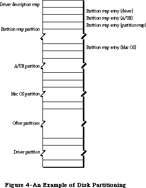 Figure 4–An Example of Disk Partitioning
The information about a partition is contained in a partition map entry; it’s shown in Figure 5.
Figure 4–An Example of Disk Partitioning
The information about a partition is contained in a partition map entry; it’s shown in Figure 5.
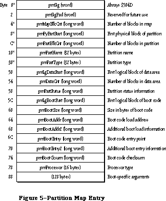 Figure 5–Partition Map Entry
The information in the fields marked with asterisks is used and expected by the Start Manager. The other fields may or may not be currently used; they’ve been defined to provide a convenient and standard way of storing information specific to your driver or operating system. To permit communication between partitions, it’s recommended that you use these fields as described below.
PMSig should always contain $504D to identify the block as containing a partition map entry. (The old partition map format, with a signature of $5453, is still supported but is discouraged.)
PMMapBlkCnt should contain the size in blocks of the partition map. The partition map entry for the partition map is not necessarily the first entry in the map. The number of blocks in the partition map is maintained in each entry, so that you can determine the size of the partition map from any entry in the map.
PMPyPartStart should give the physical block number of the first block of the partition and pmPartBlkCnt should contain the number of blocks in the partition.
PMPartName and pmPartType are both ASCII strings of 1 to 32 bytes in length; case is not significant. If either name is less than 32 characters long, it must be terminated by the NUL character (ASCII code 0). You can specify an empty name or type by setting the first byte to the NUL character.
PMPartName is similar to the handwritten label on a floppy disk; you can use this field to store a user-defined name (which may or may not be the same name used by the operating system).
PMPartType should indicate the operating system or driver using the partition. Types beginning with the string Apple_name are reserved by Apple; the following standard types have been defined:
Type Meaning
Apple_MFS Flat file system (64K ROM)
Apple_HFS Hierarchical file system (128K ROM and later)
Apple_Unix_SVR2 Partition for UNIX
Apple_partition_map Partition containing partition map
Apple_Driver Partition contains a device driver
Apple_PRODOS Partition designated for an Apple IIgs
Apple_Free Partition unused and available for assignment
Apple_Scratch Partition empty and free for use
Programmers who wish to take advantage of a checksum verification performed by the Start Manager should give a partition type of Apple_Driver and a partition name beginning with the letters “MACI” (for Macintosh). PMBootSize must contain the size in bytes of the boot code, while pmBootChecksum the checksum for that code, using the following algorithm:
DoCksum
moveq.l #0,D0 ;initialize sum register
moveq.l #0,D7 ;zero-extended byte
bra.s CkDecr ;handle 0 bytes
CkLoop
move.b (A0)+,D7 ;get a byte
add.w D7,D0 ;add to checksum
rol.w #1,D0 ;and rotate
CkDecr
dbra D1,CkLoop ;next byte
tst.w D0 ;convert a checksum of 0
bne.s @1 ; into $FFFF
subq.w #1,D0 ;
@1
With some operating systems—for instance Apple’s A/UX™ operating system—the file system may not begin at logical block 0 of the partition. You should use pmLgDataStart to store the logical block number of the first block containing the file system data and pmDataCnt to specify the size in blocks of that data area.
The low-order byte of pmPartStatus (currently used only by A/UX) contains status information about the partition, as follows:
Bit Meaning
0 Set if a valid partition map entry
1 Set if partition is already allocated; clear if available
2 Set if partition is in use; might be cleared after a system reset
3 Set if partition contains valid boot information
4 Set if partition allows reading
5 Set if partition allows writing
6 Set if boot code is position independent
7 Free for your use
The high-order byte of pmPartStatus is reserved for future use.
PMLgBootStart specifies the logical block number of the first block containing boot code.
PMBootLoad specifies the memory address where the boot code is to be loaded; pmBootLoad2 contains additional load information.
PMBootEntry specifies the memory address to which the boot code will jump after being loaded into memory; pmBootEntry2 contains additional information about this address.
PMProcessor identifies the type of processor that will execute the boot code. It’s an ASCII string of 1 to 16 bytes in length; case is not significant. If the type is less than 16 characters long, it must be terminated by the NUL character (ASCII code 0). You can specify an empty processor type by setting the first byte to the NUL character. The following processor types have been defined:
68000
68008
68010
68012
68020
_______________________________________________________________________________
»»Partitioning Guidelines
Developers writing disk partitioning (or repartitioning) programs should remember the following basic guidelines:
• Every block on a disk, with the exception of physical block 0, must belong
to a partition. Unused blocks are given the partition type Apple_Free.
• Every partition must have a partition map entry describing it. Remember
that the partition map is itself a partition, with a partition map entry
describing it. Partition map entries can be in any particular order, and
need not correspond to the order in which the partitions they describe are
located on the disk.
• Each device driver must be placed in its own partition (as opposed to
being in the partition of the operating system associated with it). This
simplifies the updating of the driver descriptor map when the driver is
moved.
• Repartitioning of a disk is a two-step process where existing partitions
must be combined to form new partitions. The existing partitions to be
combined must first be marked as type Apple_Free. As part of freeing a
partition, you must set to zero the first eight blocks (copying the
contents of the partition somewhere else) to ensure that the partition is
not mistaken for an occupied partition. Once freed, the existing
partitions can be combined with adjacent free partitions to make a single,
larger partition.
• If, as a result of repartitioning, the partition map needs additional
room, the other existing partitions can be shifted towards the “end” of
the disk. The partition map is the only partition that can be extended
without first destroying its contents.
_______________________________________________________________________________
»SUMMARY OF THE SCSI MANAGER
_______________________________________________________________________________
Constants
CONST
{ Transfer instruction operation codes }
scInc = 1; {SCINC instruction}
scNoInc = 2; {SCNOINC instruction}
scAdd = 3; {SCADD instruction}
scMove = 4; {SCMOVE instruction}
scLoop = 5; {SCLOOP instruction}
scNop = 6; {SCNOP instruction}
scStop = 7; {SCSTOP instruction}
scComp = 8; {SCCOMP instruction}
{ SCSI Manager result codes }
scCommErr 2 Breakdown in SCSI protocols: usually no device
connected or bus not terminated
scArbNBErr 3 Arbitration failed during SCSIGet; bus busy
scBadParmsErr 4 Unrecognized instruction in transfer
instruction block
scPhaseErr 5 Phase error: target and initiator not in
agreement as to type of information to transfer
scCompareErr 6 Data comparison error during read (with SCCOMP
instruction in transfer instruction block)
scMgrBusyErr 7 SCSI Manager busy with another operation
when SCSIGet was called
scSequenceErr 8 Attempted operation is out of sequence;
e.g., calling SCSISelect before doing SCSIGet
scBusTOErr 9 Bus timeout before data ready on SCSIRBlind
and SCSIWBlind
scComplPhaseErr 10 SCSIComplete failed; bus not in Status phase
_______________________________________________________________________________
Data Types
TYPE
SCSIInstr = RECORD
scOpcode: INTEGER; {operation code}
scParam1: LONGINT; {first parameter}
scParam2: LONGINT {second parameter}
END;
_______________________________________________________________________________
Routines
FUNCTION SCSIReset : OSErr;
FUNCTION SCSIGet : OSErr;
FUNCTION SCSISelect (targetID: INTEGER) : OSErr;
FUNCTION SCSICmd (buffer: Ptr; count: INTEGER) : OSErr;
FUNCTION SCSIRead (tibPtr: Ptr) : OSErr;
FUNCTION SCSIRBlind (tibPtr: Ptr) : OSErr;
FUNCTION SCSIWrite (tibPtr: Ptr ) : OSErr;
FUNCTION SCSIWBlind (tibPtr: Ptr) : OSErr;
FUNCTION SCSIComplete (VAR stat,message: INTEGER; wait: LONGINT) : OSErr;
FUNCTION SCSIStat : LONGINT;
FUNCTION SCSISelAtn (targetID: INTEGER) : OSErr;
FUNCTION SCSIMsgIn (VAR message: INTEGER) : OSErr;
FUNCTION SCSIMsgOut (message: INTEGER) : OSErr;
_______________________________________________________________________________
Assembly-Language Information
Constants
; Transfer instruction operation codes
scInc .EQU 1 ;SCINC instruction
scNoInc .EQU 2 ;SCNOINC instruction
scAdd .EQU 3 ;SCADD instruction
scMove .EQU 4 ;SCMOVE instruction
scLoop .EQU 5 ;SCLOOP instruction
scNOp .EQU 6 ;SCNOP instruction
scStop .EQU 7 ;SCSTOP instruction
scComp .EQU 8 ;SCCOMP instruction
; Routine selectors
; (Note: You can invoke each of the SCSI Manager routines
; with a macro that has the same name as the routine
; preceded by an underscore.)
scsiReset .EQU 0
scsiGet .EQU 1
scsiSelect .EQU 2
scsiCmd .EQU 3
scsiComplete .EQU 4
scsiRead .EQU 5
scsiWrite .EQU 6
scsiRBlind .EQU 8
scsiWBlind .EQU 9
scsiStat .EQU 10
scsiSelAtn .EQU 11
scsiMsgIn .EQU 12
scsiMsgOut .EQU 13
; SCSI Manager result codes
scBadParmsErr .EQU 4 ;unrecognized instruction in transfer
; instruction block
scCommErr .EQU 2 ;breakdown in SCSI protocols: usually no
; device connected or bus not terminated
scCompareErr .EQU 6 ;data comparison error during read (with scComp
; command in transfer instruction block)
scPhaseErr .EQU 5 ;phase error: target and initiator not in
; agreement as to type of information to transfer
Structure of Driver Descriptor Map
sbSig Always $4552 (word)
sbBlockSize Block size of device (word)
sbBlkCount Number of blocks on device (long)
sbDevType Used internally (word)
sbDevID Used internally (word)
sbData Used internally (long)
sbDrvrCount Number of driver descriptors (word)
Driver Descriptor Structure
ddBlock First block of driver (long)
ddSize Driver size in blocks (word)
ddType System type; 1 for Macintosh
Structure of Partition Map Entry
pmSig Always $504D (or $5453 for old format) (word)
pmSigPad Reserved for future use (word)
pmMapBlkCnt Number of blocks in partition map (long)
pmPyPartStart First physical block of partition (long)
pmPartBlkCnt Number of blocks in partition (long)
pmPartName Partition name (1–32 bytes)
pmPartType Partition type (1–32 bytes)
pmLgDataStart First logical block of data area (long)
pmDataCnt Number of blocks in data area (long)
pmPartStatus Partition status information (long)
pmLgBootStart First logical block of boot code (long)
pmBootSize Size in bytes of boot code (long)
pmBootLoad Boot code load address (long)
pmBootLoad2 Additional boot load information (long)
pmBootEntry Boot code entry point (long)
pmBootEntry2 Additional boot code entry information (long)
pmBootCksum Optional checksum (long)
pmProcessor Processor type (1–16 bytes)
Additional boot-specific arguments (128 bytes)
Trap Macro Name
_SCSIDispatch
(Note: You can invoke each of the SCSI Manager routines with a macro that
has the same name as the routine preceded by an underscore.)
Further Reference:
_______________________________________________________________________________
Device Manager
Disk Driver
Technical Note #65, Macintosh Plus Pinouts
Technical Note #96, SCSI Bugs
Technical Note #134, Hard Disk Medic & Booting Camp
Technical Note #159, Hard Disk Hacking
Technical Note #258, Our Checksum Bounced
“Macintosh Family Hardware Reference”
Figure 5–Partition Map Entry
The information in the fields marked with asterisks is used and expected by the Start Manager. The other fields may or may not be currently used; they’ve been defined to provide a convenient and standard way of storing information specific to your driver or operating system. To permit communication between partitions, it’s recommended that you use these fields as described below.
PMSig should always contain $504D to identify the block as containing a partition map entry. (The old partition map format, with a signature of $5453, is still supported but is discouraged.)
PMMapBlkCnt should contain the size in blocks of the partition map. The partition map entry for the partition map is not necessarily the first entry in the map. The number of blocks in the partition map is maintained in each entry, so that you can determine the size of the partition map from any entry in the map.
PMPyPartStart should give the physical block number of the first block of the partition and pmPartBlkCnt should contain the number of blocks in the partition.
PMPartName and pmPartType are both ASCII strings of 1 to 32 bytes in length; case is not significant. If either name is less than 32 characters long, it must be terminated by the NUL character (ASCII code 0). You can specify an empty name or type by setting the first byte to the NUL character.
PMPartName is similar to the handwritten label on a floppy disk; you can use this field to store a user-defined name (which may or may not be the same name used by the operating system).
PMPartType should indicate the operating system or driver using the partition. Types beginning with the string Apple_name are reserved by Apple; the following standard types have been defined:
Type Meaning
Apple_MFS Flat file system (64K ROM)
Apple_HFS Hierarchical file system (128K ROM and later)
Apple_Unix_SVR2 Partition for UNIX
Apple_partition_map Partition containing partition map
Apple_Driver Partition contains a device driver
Apple_PRODOS Partition designated for an Apple IIgs
Apple_Free Partition unused and available for assignment
Apple_Scratch Partition empty and free for use
Programmers who wish to take advantage of a checksum verification performed by the Start Manager should give a partition type of Apple_Driver and a partition name beginning with the letters “MACI” (for Macintosh). PMBootSize must contain the size in bytes of the boot code, while pmBootChecksum the checksum for that code, using the following algorithm:
DoCksum
moveq.l #0,D0 ;initialize sum register
moveq.l #0,D7 ;zero-extended byte
bra.s CkDecr ;handle 0 bytes
CkLoop
move.b (A0)+,D7 ;get a byte
add.w D7,D0 ;add to checksum
rol.w #1,D0 ;and rotate
CkDecr
dbra D1,CkLoop ;next byte
tst.w D0 ;convert a checksum of 0
bne.s @1 ; into $FFFF
subq.w #1,D0 ;
@1
With some operating systems—for instance Apple’s A/UX™ operating system—the file system may not begin at logical block 0 of the partition. You should use pmLgDataStart to store the logical block number of the first block containing the file system data and pmDataCnt to specify the size in blocks of that data area.
The low-order byte of pmPartStatus (currently used only by A/UX) contains status information about the partition, as follows:
Bit Meaning
0 Set if a valid partition map entry
1 Set if partition is already allocated; clear if available
2 Set if partition is in use; might be cleared after a system reset
3 Set if partition contains valid boot information
4 Set if partition allows reading
5 Set if partition allows writing
6 Set if boot code is position independent
7 Free for your use
The high-order byte of pmPartStatus is reserved for future use.
PMLgBootStart specifies the logical block number of the first block containing boot code.
PMBootLoad specifies the memory address where the boot code is to be loaded; pmBootLoad2 contains additional load information.
PMBootEntry specifies the memory address to which the boot code will jump after being loaded into memory; pmBootEntry2 contains additional information about this address.
PMProcessor identifies the type of processor that will execute the boot code. It’s an ASCII string of 1 to 16 bytes in length; case is not significant. If the type is less than 16 characters long, it must be terminated by the NUL character (ASCII code 0). You can specify an empty processor type by setting the first byte to the NUL character. The following processor types have been defined:
68000
68008
68010
68012
68020
_______________________________________________________________________________
»»Partitioning Guidelines
Developers writing disk partitioning (or repartitioning) programs should remember the following basic guidelines:
• Every block on a disk, with the exception of physical block 0, must belong
to a partition. Unused blocks are given the partition type Apple_Free.
• Every partition must have a partition map entry describing it. Remember
that the partition map is itself a partition, with a partition map entry
describing it. Partition map entries can be in any particular order, and
need not correspond to the order in which the partitions they describe are
located on the disk.
• Each device driver must be placed in its own partition (as opposed to
being in the partition of the operating system associated with it). This
simplifies the updating of the driver descriptor map when the driver is
moved.
• Repartitioning of a disk is a two-step process where existing partitions
must be combined to form new partitions. The existing partitions to be
combined must first be marked as type Apple_Free. As part of freeing a
partition, you must set to zero the first eight blocks (copying the
contents of the partition somewhere else) to ensure that the partition is
not mistaken for an occupied partition. Once freed, the existing
partitions can be combined with adjacent free partitions to make a single,
larger partition.
• If, as a result of repartitioning, the partition map needs additional
room, the other existing partitions can be shifted towards the “end” of
the disk. The partition map is the only partition that can be extended
without first destroying its contents.
_______________________________________________________________________________
»SUMMARY OF THE SCSI MANAGER
_______________________________________________________________________________
Constants
CONST
{ Transfer instruction operation codes }
scInc = 1; {SCINC instruction}
scNoInc = 2; {SCNOINC instruction}
scAdd = 3; {SCADD instruction}
scMove = 4; {SCMOVE instruction}
scLoop = 5; {SCLOOP instruction}
scNop = 6; {SCNOP instruction}
scStop = 7; {SCSTOP instruction}
scComp = 8; {SCCOMP instruction}
{ SCSI Manager result codes }
scCommErr 2 Breakdown in SCSI protocols: usually no device
connected or bus not terminated
scArbNBErr 3 Arbitration failed during SCSIGet; bus busy
scBadParmsErr 4 Unrecognized instruction in transfer
instruction block
scPhaseErr 5 Phase error: target and initiator not in
agreement as to type of information to transfer
scCompareErr 6 Data comparison error during read (with SCCOMP
instruction in transfer instruction block)
scMgrBusyErr 7 SCSI Manager busy with another operation
when SCSIGet was called
scSequenceErr 8 Attempted operation is out of sequence;
e.g., calling SCSISelect before doing SCSIGet
scBusTOErr 9 Bus timeout before data ready on SCSIRBlind
and SCSIWBlind
scComplPhaseErr 10 SCSIComplete failed; bus not in Status phase
_______________________________________________________________________________
Data Types
TYPE
SCSIInstr = RECORD
scOpcode: INTEGER; {operation code}
scParam1: LONGINT; {first parameter}
scParam2: LONGINT {second parameter}
END;
_______________________________________________________________________________
Routines
FUNCTION SCSIReset : OSErr;
FUNCTION SCSIGet : OSErr;
FUNCTION SCSISelect (targetID: INTEGER) : OSErr;
FUNCTION SCSICmd (buffer: Ptr; count: INTEGER) : OSErr;
FUNCTION SCSIRead (tibPtr: Ptr) : OSErr;
FUNCTION SCSIRBlind (tibPtr: Ptr) : OSErr;
FUNCTION SCSIWrite (tibPtr: Ptr ) : OSErr;
FUNCTION SCSIWBlind (tibPtr: Ptr) : OSErr;
FUNCTION SCSIComplete (VAR stat,message: INTEGER; wait: LONGINT) : OSErr;
FUNCTION SCSIStat : LONGINT;
FUNCTION SCSISelAtn (targetID: INTEGER) : OSErr;
FUNCTION SCSIMsgIn (VAR message: INTEGER) : OSErr;
FUNCTION SCSIMsgOut (message: INTEGER) : OSErr;
_______________________________________________________________________________
Assembly-Language Information
Constants
; Transfer instruction operation codes
scInc .EQU 1 ;SCINC instruction
scNoInc .EQU 2 ;SCNOINC instruction
scAdd .EQU 3 ;SCADD instruction
scMove .EQU 4 ;SCMOVE instruction
scLoop .EQU 5 ;SCLOOP instruction
scNOp .EQU 6 ;SCNOP instruction
scStop .EQU 7 ;SCSTOP instruction
scComp .EQU 8 ;SCCOMP instruction
; Routine selectors
; (Note: You can invoke each of the SCSI Manager routines
; with a macro that has the same name as the routine
; preceded by an underscore.)
scsiReset .EQU 0
scsiGet .EQU 1
scsiSelect .EQU 2
scsiCmd .EQU 3
scsiComplete .EQU 4
scsiRead .EQU 5
scsiWrite .EQU 6
scsiRBlind .EQU 8
scsiWBlind .EQU 9
scsiStat .EQU 10
scsiSelAtn .EQU 11
scsiMsgIn .EQU 12
scsiMsgOut .EQU 13
; SCSI Manager result codes
scBadParmsErr .EQU 4 ;unrecognized instruction in transfer
; instruction block
scCommErr .EQU 2 ;breakdown in SCSI protocols: usually no
; device connected or bus not terminated
scCompareErr .EQU 6 ;data comparison error during read (with scComp
; command in transfer instruction block)
scPhaseErr .EQU 5 ;phase error: target and initiator not in
; agreement as to type of information to transfer
Structure of Driver Descriptor Map
sbSig Always $4552 (word)
sbBlockSize Block size of device (word)
sbBlkCount Number of blocks on device (long)
sbDevType Used internally (word)
sbDevID Used internally (word)
sbData Used internally (long)
sbDrvrCount Number of driver descriptors (word)
Driver Descriptor Structure
ddBlock First block of driver (long)
ddSize Driver size in blocks (word)
ddType System type; 1 for Macintosh
Structure of Partition Map Entry
pmSig Always $504D (or $5453 for old format) (word)
pmSigPad Reserved for future use (word)
pmMapBlkCnt Number of blocks in partition map (long)
pmPyPartStart First physical block of partition (long)
pmPartBlkCnt Number of blocks in partition (long)
pmPartName Partition name (1–32 bytes)
pmPartType Partition type (1–32 bytes)
pmLgDataStart First logical block of data area (long)
pmDataCnt Number of blocks in data area (long)
pmPartStatus Partition status information (long)
pmLgBootStart First logical block of boot code (long)
pmBootSize Size in bytes of boot code (long)
pmBootLoad Boot code load address (long)
pmBootLoad2 Additional boot load information (long)
pmBootEntry Boot code entry point (long)
pmBootEntry2 Additional boot code entry information (long)
pmBootCksum Optional checksum (long)
pmProcessor Processor type (1–16 bytes)
Additional boot-specific arguments (128 bytes)
Trap Macro Name
_SCSIDispatch
(Note: You can invoke each of the SCSI Manager routines with a macro that
has the same name as the routine preceded by an underscore.)
Further Reference:
_______________________________________________________________________________
Device Manager
Disk Driver
Technical Note #65, Macintosh Plus Pinouts
Technical Note #96, SCSI Bugs
Technical Note #134, Hard Disk Medic & Booting Camp
Technical Note #159, Hard Disk Hacking
Technical Note #258, Our Checksum Bounced
“Macintosh Family Hardware Reference”
The Segment Loader
_______________________________________________________________________________
THE SEGMENT LOADER
_______________________________________________________________________________
About This Chapter
About the Segment Loader
Finder Information
Using the Segment Loader
Segment Loader Routines
Advanced Routines
The Jump Table
Summary of the Segment Loader
_______________________________________________________________________________
»ABOUT THIS CHAPTER
_______________________________________________________________________________
This chapter describes the Segment Loader, the part of the Macintosh Operating System that lets you divide your application into several parts and have only some of them in memory at a time. The Segment Loader also provides routines for accessing information about documents that the user has selected to be opened or printed.
You should already be familiar with:
• the basic concepts behind the Resource Manager
• the Memory Manager
_______________________________________________________________________________
»ABOUT THE SEGMENT LOADER
_______________________________________________________________________________
The Segment Loader allows you to divide the code of your application into several parts or segments. The Finder starts up an application by calling a Segment Loader routine that loads in the main segment (the one containing the main program). Other segments are loaded in automatically when they’re needed. Your application can call the Segment Loader to have these segments removed from memory when they’re no longer needed.
The Segment Loader enables you to have programs larger than 32K bytes, the maximum size of a single segment. Also, any code that isn’t executed often
(such as code for printing) needn’t occupy memory when it isn’t being used, but can instead be in a separate segment that’s “swapped in” when needed.
This mechanism may remind you of the resources of an application, which the Resource Manager reads into memory when necessary. An application’s segments are in fact themselves stored as resources; their resource type is 'CODE'. A
“loaded” segment has been read into memory by the Resource Manager and locked
(so that it’s neither relocatable nor purgeable). When a segment is unloaded, it’s made relocatable and purgeable.
Every segment has a name. If you do nothing about dividing your program into segments, it will consist only of the main segment. Dividing your program into segments means specifying in your source file the beginning of each segment by name. The names are for your use only; they’re not kept around after linking.
_______________________________________________________________________________
»FINDER INFORMATION
_______________________________________________________________________________
When the Finder starts up your application, it passes along a list of documents selected by the user to be printed or opened, if any. This information is called the Finder information; its structure is shown in Figure 1.
It’s up to your application to access the Finder information and open or print the documents selected by the user.
The message in the first word of the Finder information indicates whether the documents are to be opened (0) or printed (1), and the count following it indicates the number of documents (0 if none). The rest of the Finder information specifies each of the selected documents by volume reference number, file type, version number, and file name; these terms are explained in the File Manager chapter and the Finder Interface chapter. File names are padded to an even number of bytes if necessary.
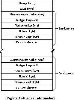 Figure 1–Finder Information
Your application should start up with an empty untitled document on the desktop if there are no documents listed in the Finder information. If one or more documents are to be opened, your application should go through each document one at a time, and determine whether it can be opened. If it can be opened, you should do so, and then check the next document in the list (unless you’ve opened your maximum number of documents, in which case you should ignore the rest). If your application doesn’t recognize a document’s file type (which can happen if the user selected your application along with another application’s document), you may want to open the document anyway and check its internal structure to see if it’s a compatible type. Display an alert box including the name of each document that can’t be opened.
If one or more documents are to be printed, your application should go through each document in the list and determine whether it can be printed. If any documents can be printed, the application should display the standard Print dialog box and then print each document—preferably without doing its entire startup sequence. For example, it may not be necessary to show the menu bar or the document window. If the document can’t be printed, ignore it; it may be intended for another application.
_______________________________________________________________________________
»USING THE SEGMENT LOADER
_______________________________________________________________________________
When your application starts up, you should determine whether any documents were selected to be printed or opened by it. First call CountAppFiles, which returns the number of selected documents and indicates whether they’re to be printed or opened. If the number of selected documents is 0, open an empty untitled document in the normal manner. Otherwise, call GetAppFiles once for each selected document. GetAppFiles returns information about each document, including its file type. Based on the file type, your application can decide how to treat the document, as described in the preceding section. For each document that your application opens or prints, call ClrAppFiles, which indicates to the Finder that you’ve processed it.
To unload a segment when it’s no longer needed, call UnloadSeg. If you don’t want to keep track of when each particular segment should be unloaded, you can call UnloadSeg for every segment in your application at the end of your main event loop. This isn’t harmful, since the segments aren’t purged unless necessary.
Note: The main segment is always loaded and locked.
Warning: A segment should never unload the segment that called it, because
the return addresses on the stack would refer to code that may be
moved or purged.
Another procedure, GetAppParms, lets you get information about your application such as its name and the reference number for its resource file. The Segment Loader also provides the ExitToShell procedure—a way for an application to quit and return the user to the Finder.
Finally, there are three advanced routines that can be called only from assembly language: Chain, Launch, and LoadSeg. Chain starts up another application without disturbing the application heap. Thus the current application can let another application take over while still keeping its data around in the heap. Launch is called by the Finder to start up an application; it’s like Chain but doesn’t retain the application heap. LoadSeg is called indirectly (via the jump table, as described later) to load segments when necessary—that is, whenever a routine in an unloaded segment is invoked.
_______________________________________________________________________________
»SEGMENT LOADER ROUTINES
_______________________________________________________________________________
Assembly-language note: Instead of using CountAppFiles, GetAppFiles, and
ClrAppFiles, assembly-language programmers can access
the Finder information via the global variable
AppParmHandle, which contains a handle to the Finder
information. Parse the Finder information as shown in
Figure 1 above. For each document that your
application opens or prints, set the file type in the
Finder information to 0.
PROCEDURE CountAppFiles (VAR message: INTEGER;
VAR count: INTEGER); [Not in ROM]
CountAppFiles deciphers the Finder information passed to your application, and returns information about the documents that were selected when your application started up. It returns the number of selected documents in the count parameter, and a number in the message parameter that indicates whether the documents are to opened or printed:
CONST appOpen = 0; {open the document(s)}
appPrint = 1; {print the document(s)}
PROCEDURE GetAppFiles (index: INTEGER; VAR theFile: AppFile); [Not in ROM]
GetAppFiles returns information about a document that was selected when your application started up (as listed in the Finder information). The index parameter indicates the file for which information should be returned; it must be between 1 and the number returned by CountAppFiles, inclusive. The information is returned in the following data structure:
TYPE AppFile = RECORD
vRefNum: INTEGER; {volume reference number}
fType: OSType; {file type}
versNum: INTEGER; {version number}
fName: Str255 {file name}
END;
PROCEDURE ClrAppFiles (index: INTEGER); [Not in ROM]
ClrAppFiles changes the Finder information passed to your application about the specified file such that the Finder knows you’ve processed the file. The index parameter must be between 1 and the number returned by CountAppFiles. You should call ClrAppFiles for every document your application opens or prints, so that the information returned by CountAppFiles and GetAppFiles is always correct. (ClrAppFiles sets the file type in the Finder information to 0.)
PROCEDURE GetAppParms (VAR apName: Str255; VAR apRefNum: INTEGER;
VAR apParam: Handle);
GetAppParms returns information about the current application. It returns the application name in apName and the reference number for the application’s resource file in apRefNum. A handle to the Finder information is returned in apParam, but the Finder information is more easily accessed with the GetAppFiles call.
Assembly-language note: Assembly-language programmers can instead get the
application name, reference number, and handle to the
Finder information directly from the global variables
CurApName, CurApRefNum, and AppParmHandle.
Note: If you simply want the application’s resource file reference number,
you can call the Resource Manager function CurResFile when the
application starts up.
PROCEDURE UnloadSeg (routineAddr: Ptr);
UnloadSeg unloads a segment, making it relocatable and purgeable; routineAddr is the address of any externally referenced routine in the segment. The segment won’t actually be purged until the memory it occupies is needed. If the segment is purged, the Segment Loader will reload it the next time one of the routines in it is called.
Note: UnloadSeg will work only if called from outside the segment to be
unloaded.
PROCEDURE ExitToShell;
ExitToShell provides an exit from an application by starting up the Finder
(after releasing the entire application heap).
Assembly-language note: ExitToShell actually launches the application whose
name is stored in the global variable FinderName.
_______________________________________________________________________________
»Advanced Routines
The routines below are provided for advanced programmers; they can be called only from assembly language.
Chain procedure
Trap macro _Chain
On entry (A0): pointer to application’s file name (preceded by length byte)
4(A0): configuration of sound and screen buffers (word)
Chain starts up an application without doing anything to the application heap, so the current application can let another application take over while still keeping its data around in the heap.
Chain also configures memory for the sound and screen buffers. The value you pass in 4(A0) determines which sound and screen buffers are allocated:
• If you pass 0 in 4(A0), you get the main sound and screen buffers; in this
case, you have the largest amount of memory available to your application.
• Any positive value in 4(A0) causes the alternate sound buffer and main
screen buffer to be allocated.
• Any negative value in 4(A0) causes the alternate sound buffer and
alternate screen buffer to be allocated.
The memory map in the Memory Manager chapter shows the locations of the screen and sound buffers.
Warning: The sound buffers and alternate screen buffer are only supported on
the Macintosh 128K, 512K (and enhanced), Plus, and SE models.
Note: You can get the most recent value passed in 4(A0) to the Chain procedure
from the global variable CurPageOption.
Chain closes the resource file for any previous application and opens the resource file for the application being started; call DetachResource for any resources that you still wish to access.
Launch procedure
X-Ref: Technical Note #126
Trap macro _Launch
On entry (A0): pointer to application’s file name (preceded by length byte)
4(A0): configuration of sound and screen buffers (word)
Launch is called by the Finder to start up an application and will rarely need to be called by an application itself. It’s the same as the Chain procedure
(described above) except that it frees the storage occupied by the application heap and restores the heap to its original size.
Note: Launch preserves a special handle in the application heap which is used
for preserving the desk scrap between applications; see the Scrap
Manager chapter for details.
LoadSeg procedure
Trap macro _LoadSeg
On entry stack: segment number (word)
LoadSeg is called indirectly via the jump table (as described in the following section) when the application calls a routine in an unloaded segment. It loads the segment having the given segment number, which was assigned by the Linker. If the segment isn’t in memory, LoadSeg calls the Resource Manager to read it in. It changes the jump table entries for all the routines in the segment from the “unloaded” to the “loaded” state and then invokes the routine that was called.
Note: Since LoadSeg is called via the jump table, there isn’t any need for
you to call it yourself.
Advanced programmers: The LoadSeg procedure has been modified to help reduce
heap fragmentation. If the code segment to be loaded is
unlocked (that is, if it’s not in memory and its
resLocked attribute is clear, or if it is in memory and
is unlocked), LoadSeg calls the Memory Manager procedure
MoveHHi to move the segment toward the top of the
current heap zone.
To maintain compatibility with the 64K ROM, your code segments should be locked in the resource file. They will, however, be unlocked when they’re unloaded and may float up in the heap; subsequent loading may then cause heap fragmentation.
If your application will never run on a 64K ROM machine, all segments except the main segment ('CODE' resource 1) can be unlocked in the resource file. Your application’s initialization routine must call the Memory Manager procedure MaxApplZone, however; otherwise the heap zone will grow incrementally and calls to MoveHHi may leave your segments scattered throughout the heap.
_______________________________________________________________________________
»THE JUMP TABLE
_______________________________________________________________________________
This section describes how the Segment Loader works internally, and is included here for advanced programmers; you don’t have to know about this to be able to use the common Segment Loader routines.
The loading and unloading of segments is implemented through the application’s jump table. The jump table contains one eight-byte entry for every externally referenced routine in every segment; all the entries for a particular segment are stored contiguously. The location of the jump table is shown in the Memory Manager chapter.
When the Linker encounters a call to a routine in another segment, it creates a jump table entry for the routine (see Figure 2). The jump table refers to segments by segment numbers assigned by the Linker. If the segment is loaded, the jump table entry contains code that jumps to the routine. If the segment isn’t loaded, the entry contains code that loads the segment.
Figure 1–Finder Information
Your application should start up with an empty untitled document on the desktop if there are no documents listed in the Finder information. If one or more documents are to be opened, your application should go through each document one at a time, and determine whether it can be opened. If it can be opened, you should do so, and then check the next document in the list (unless you’ve opened your maximum number of documents, in which case you should ignore the rest). If your application doesn’t recognize a document’s file type (which can happen if the user selected your application along with another application’s document), you may want to open the document anyway and check its internal structure to see if it’s a compatible type. Display an alert box including the name of each document that can’t be opened.
If one or more documents are to be printed, your application should go through each document in the list and determine whether it can be printed. If any documents can be printed, the application should display the standard Print dialog box and then print each document—preferably without doing its entire startup sequence. For example, it may not be necessary to show the menu bar or the document window. If the document can’t be printed, ignore it; it may be intended for another application.
_______________________________________________________________________________
»USING THE SEGMENT LOADER
_______________________________________________________________________________
When your application starts up, you should determine whether any documents were selected to be printed or opened by it. First call CountAppFiles, which returns the number of selected documents and indicates whether they’re to be printed or opened. If the number of selected documents is 0, open an empty untitled document in the normal manner. Otherwise, call GetAppFiles once for each selected document. GetAppFiles returns information about each document, including its file type. Based on the file type, your application can decide how to treat the document, as described in the preceding section. For each document that your application opens or prints, call ClrAppFiles, which indicates to the Finder that you’ve processed it.
To unload a segment when it’s no longer needed, call UnloadSeg. If you don’t want to keep track of when each particular segment should be unloaded, you can call UnloadSeg for every segment in your application at the end of your main event loop. This isn’t harmful, since the segments aren’t purged unless necessary.
Note: The main segment is always loaded and locked.
Warning: A segment should never unload the segment that called it, because
the return addresses on the stack would refer to code that may be
moved or purged.
Another procedure, GetAppParms, lets you get information about your application such as its name and the reference number for its resource file. The Segment Loader also provides the ExitToShell procedure—a way for an application to quit and return the user to the Finder.
Finally, there are three advanced routines that can be called only from assembly language: Chain, Launch, and LoadSeg. Chain starts up another application without disturbing the application heap. Thus the current application can let another application take over while still keeping its data around in the heap. Launch is called by the Finder to start up an application; it’s like Chain but doesn’t retain the application heap. LoadSeg is called indirectly (via the jump table, as described later) to load segments when necessary—that is, whenever a routine in an unloaded segment is invoked.
_______________________________________________________________________________
»SEGMENT LOADER ROUTINES
_______________________________________________________________________________
Assembly-language note: Instead of using CountAppFiles, GetAppFiles, and
ClrAppFiles, assembly-language programmers can access
the Finder information via the global variable
AppParmHandle, which contains a handle to the Finder
information. Parse the Finder information as shown in
Figure 1 above. For each document that your
application opens or prints, set the file type in the
Finder information to 0.
PROCEDURE CountAppFiles (VAR message: INTEGER;
VAR count: INTEGER); [Not in ROM]
CountAppFiles deciphers the Finder information passed to your application, and returns information about the documents that were selected when your application started up. It returns the number of selected documents in the count parameter, and a number in the message parameter that indicates whether the documents are to opened or printed:
CONST appOpen = 0; {open the document(s)}
appPrint = 1; {print the document(s)}
PROCEDURE GetAppFiles (index: INTEGER; VAR theFile: AppFile); [Not in ROM]
GetAppFiles returns information about a document that was selected when your application started up (as listed in the Finder information). The index parameter indicates the file for which information should be returned; it must be between 1 and the number returned by CountAppFiles, inclusive. The information is returned in the following data structure:
TYPE AppFile = RECORD
vRefNum: INTEGER; {volume reference number}
fType: OSType; {file type}
versNum: INTEGER; {version number}
fName: Str255 {file name}
END;
PROCEDURE ClrAppFiles (index: INTEGER); [Not in ROM]
ClrAppFiles changes the Finder information passed to your application about the specified file such that the Finder knows you’ve processed the file. The index parameter must be between 1 and the number returned by CountAppFiles. You should call ClrAppFiles for every document your application opens or prints, so that the information returned by CountAppFiles and GetAppFiles is always correct. (ClrAppFiles sets the file type in the Finder information to 0.)
PROCEDURE GetAppParms (VAR apName: Str255; VAR apRefNum: INTEGER;
VAR apParam: Handle);
GetAppParms returns information about the current application. It returns the application name in apName and the reference number for the application’s resource file in apRefNum. A handle to the Finder information is returned in apParam, but the Finder information is more easily accessed with the GetAppFiles call.
Assembly-language note: Assembly-language programmers can instead get the
application name, reference number, and handle to the
Finder information directly from the global variables
CurApName, CurApRefNum, and AppParmHandle.
Note: If you simply want the application’s resource file reference number,
you can call the Resource Manager function CurResFile when the
application starts up.
PROCEDURE UnloadSeg (routineAddr: Ptr);
UnloadSeg unloads a segment, making it relocatable and purgeable; routineAddr is the address of any externally referenced routine in the segment. The segment won’t actually be purged until the memory it occupies is needed. If the segment is purged, the Segment Loader will reload it the next time one of the routines in it is called.
Note: UnloadSeg will work only if called from outside the segment to be
unloaded.
PROCEDURE ExitToShell;
ExitToShell provides an exit from an application by starting up the Finder
(after releasing the entire application heap).
Assembly-language note: ExitToShell actually launches the application whose
name is stored in the global variable FinderName.
_______________________________________________________________________________
»Advanced Routines
The routines below are provided for advanced programmers; they can be called only from assembly language.
Chain procedure
Trap macro _Chain
On entry (A0): pointer to application’s file name (preceded by length byte)
4(A0): configuration of sound and screen buffers (word)
Chain starts up an application without doing anything to the application heap, so the current application can let another application take over while still keeping its data around in the heap.
Chain also configures memory for the sound and screen buffers. The value you pass in 4(A0) determines which sound and screen buffers are allocated:
• If you pass 0 in 4(A0), you get the main sound and screen buffers; in this
case, you have the largest amount of memory available to your application.
• Any positive value in 4(A0) causes the alternate sound buffer and main
screen buffer to be allocated.
• Any negative value in 4(A0) causes the alternate sound buffer and
alternate screen buffer to be allocated.
The memory map in the Memory Manager chapter shows the locations of the screen and sound buffers.
Warning: The sound buffers and alternate screen buffer are only supported on
the Macintosh 128K, 512K (and enhanced), Plus, and SE models.
Note: You can get the most recent value passed in 4(A0) to the Chain procedure
from the global variable CurPageOption.
Chain closes the resource file for any previous application and opens the resource file for the application being started; call DetachResource for any resources that you still wish to access.
Launch procedure
X-Ref: Technical Note #126
Trap macro _Launch
On entry (A0): pointer to application’s file name (preceded by length byte)
4(A0): configuration of sound and screen buffers (word)
Launch is called by the Finder to start up an application and will rarely need to be called by an application itself. It’s the same as the Chain procedure
(described above) except that it frees the storage occupied by the application heap and restores the heap to its original size.
Note: Launch preserves a special handle in the application heap which is used
for preserving the desk scrap between applications; see the Scrap
Manager chapter for details.
LoadSeg procedure
Trap macro _LoadSeg
On entry stack: segment number (word)
LoadSeg is called indirectly via the jump table (as described in the following section) when the application calls a routine in an unloaded segment. It loads the segment having the given segment number, which was assigned by the Linker. If the segment isn’t in memory, LoadSeg calls the Resource Manager to read it in. It changes the jump table entries for all the routines in the segment from the “unloaded” to the “loaded” state and then invokes the routine that was called.
Note: Since LoadSeg is called via the jump table, there isn’t any need for
you to call it yourself.
Advanced programmers: The LoadSeg procedure has been modified to help reduce
heap fragmentation. If the code segment to be loaded is
unlocked (that is, if it’s not in memory and its
resLocked attribute is clear, or if it is in memory and
is unlocked), LoadSeg calls the Memory Manager procedure
MoveHHi to move the segment toward the top of the
current heap zone.
To maintain compatibility with the 64K ROM, your code segments should be locked in the resource file. They will, however, be unlocked when they’re unloaded and may float up in the heap; subsequent loading may then cause heap fragmentation.
If your application will never run on a 64K ROM machine, all segments except the main segment ('CODE' resource 1) can be unlocked in the resource file. Your application’s initialization routine must call the Memory Manager procedure MaxApplZone, however; otherwise the heap zone will grow incrementally and calls to MoveHHi may leave your segments scattered throughout the heap.
_______________________________________________________________________________
»THE JUMP TABLE
_______________________________________________________________________________
This section describes how the Segment Loader works internally, and is included here for advanced programmers; you don’t have to know about this to be able to use the common Segment Loader routines.
The loading and unloading of segments is implemented through the application’s jump table. The jump table contains one eight-byte entry for every externally referenced routine in every segment; all the entries for a particular segment are stored contiguously. The location of the jump table is shown in the Memory Manager chapter.
When the Linker encounters a call to a routine in another segment, it creates a jump table entry for the routine (see Figure 2). The jump table refers to segments by segment numbers assigned by the Linker. If the segment is loaded, the jump table entry contains code that jumps to the routine. If the segment isn’t loaded, the entry contains code that loads the segment.
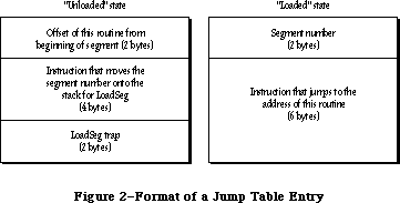 Figure 2–Format of a Jump Table Entry
X-Ref: Technical Note #220
When a segment is unloaded, all its jump table entries are in the “unloaded” state. When a call to a routine in an unloaded segment is made, the code in the last six bytes of its jump table entry is executed. This code calls LoadSeg, which loads the segment into memory, transforms all of its jump table entries to the “loaded” state, and invokes the routine by executing the instruction in the last six bytes of the jump table entry. Subsequent calls to the routine also execute this instruction. If UnloadSeg is called to unload the segment, it restores the jump table entries to their “unloaded” state. Notice that whether the segment is loaded or unloaded, the last six bytes of the jump table entry are executed; the effect depends on the state of the entry at the time.
To be able to set all the jump table entries for a segment to a particular state, LoadSeg and UnloadSeg need to know exactly where in the jump table all the entries are located. They get this information from the segment header, four bytes at the beginning of the segment which contain the following:
Number of bytes Contents
2 bytes Offset of the first routine’s entry from the
beginning of the jump table
2 bytes Number of entries for this segment
When an application starts up, its jump table is read in from segment 0 (which is the 'CODE' resource with an ID of 0). This is a special segment created by the Linker for every executable file. It contains the following:
Number of bytes Contents
4 bytes “Above A5” size; size in bytes from location pointed
to by A5 to upper end of application space
4 bytes “Below A5” size; size in bytes of application globals
plus QuickDraw globals
4 bytes Length of jump table in bytes
4 bytes Offset to jump table from location pointed to by A5
n bytes Jump table
Note: For all applications, the offset to the jump table from the location
pointed to by A5 is 32, and the “above A5” size is 32 plus the length
of the jump table.
The Segment Loader then executes the first entry in the jump table, which loads the main segment ('CODE' resource 1) and starts the application.
Assembly-language note: The offset to the jump table from the location
pointed to by A5 is stored in the global variable
CurJTOffset.
_______________________________________________________________________________
»SUMMARY OF THE SEGMENT LOADER
_______________________________________________________________________________
Constants
CONST
{ Message returned by CountAppleFiles }
appOpen = 0; {open the document(s)}
appPrint = 1; {print the document(s)}
_______________________________________________________________________________
Data Types
TYPE
AppFile = RECORD
vRefNum: INTEGER; {volume reference number}
fType: OSType; {file type}
versNum: INTEGER; {version number}
fName: Str255 {file name}
END;
_______________________________________________________________________________
Routines
PROCEDURE CountAppFiles (VAR message: INTEGER; VAR count: INTEGER);
[Not in ROM]
PROCEDURE GetAppFiles (index: INTEGER; VAR theFile: AppFile); [Not in ROM]
PROCEDURE ClrAppFiles (index: INTEGER); [Not in ROM]
PROCEDURE GetAppParms (VAR apName: Str255; VAR apRefNum: INTEGER;
VAR apParam: Handle);
PROCEDURE UnloadSeg (routineAddr: Ptr);
PROCEDURE ExitToShell;
_______________________________________________________________________________
Assembly-Language Information
Advanced Routines
Trap macro On entry
_Chain (A0): pointer to application’s file name (preceded by length byte)
4(A0): configuration of sound and screen buffers (word)
_Launch (A0): pointer to application’s file name (preceded by length byte)
4(A0): configuration of sound and screen buffers (word)
_LoadSeg stack: segment number (word)
Variables
AppParmHandle Handle to Finder information
CurApName Name of current application (length byte followed
by up to 31 characters)
CurApRefNum Reference number of current application’s resource file (word)
CurPageOption Sound/screen buffer configuration passed to Chain or
Launch (word)
CurJTOffset Offset to jump table from location pointed to by A5 (word)
FinderName Name of the Finder (length byte followed by up to 15 characters)
Further Reference:
_______________________________________________________________________________
Resource Manager
Memory Manager
Technical Note #43, Calling LoadSeg
Technical Note #113, Boot Blocks
Technical Note #126, Sub(Launching) from a High-Level Language
Technical Note #220, Segment Loader Limitations
Technical Note #239, Inside Object Pascal
Technical Note #240, Using MPW for Non-Macintosh 68000 Systems
Technical Note #256, Stand-Alone Code, ad nauseam
Figure 2–Format of a Jump Table Entry
X-Ref: Technical Note #220
When a segment is unloaded, all its jump table entries are in the “unloaded” state. When a call to a routine in an unloaded segment is made, the code in the last six bytes of its jump table entry is executed. This code calls LoadSeg, which loads the segment into memory, transforms all of its jump table entries to the “loaded” state, and invokes the routine by executing the instruction in the last six bytes of the jump table entry. Subsequent calls to the routine also execute this instruction. If UnloadSeg is called to unload the segment, it restores the jump table entries to their “unloaded” state. Notice that whether the segment is loaded or unloaded, the last six bytes of the jump table entry are executed; the effect depends on the state of the entry at the time.
To be able to set all the jump table entries for a segment to a particular state, LoadSeg and UnloadSeg need to know exactly where in the jump table all the entries are located. They get this information from the segment header, four bytes at the beginning of the segment which contain the following:
Number of bytes Contents
2 bytes Offset of the first routine’s entry from the
beginning of the jump table
2 bytes Number of entries for this segment
When an application starts up, its jump table is read in from segment 0 (which is the 'CODE' resource with an ID of 0). This is a special segment created by the Linker for every executable file. It contains the following:
Number of bytes Contents
4 bytes “Above A5” size; size in bytes from location pointed
to by A5 to upper end of application space
4 bytes “Below A5” size; size in bytes of application globals
plus QuickDraw globals
4 bytes Length of jump table in bytes
4 bytes Offset to jump table from location pointed to by A5
n bytes Jump table
Note: For all applications, the offset to the jump table from the location
pointed to by A5 is 32, and the “above A5” size is 32 plus the length
of the jump table.
The Segment Loader then executes the first entry in the jump table, which loads the main segment ('CODE' resource 1) and starts the application.
Assembly-language note: The offset to the jump table from the location
pointed to by A5 is stored in the global variable
CurJTOffset.
_______________________________________________________________________________
»SUMMARY OF THE SEGMENT LOADER
_______________________________________________________________________________
Constants
CONST
{ Message returned by CountAppleFiles }
appOpen = 0; {open the document(s)}
appPrint = 1; {print the document(s)}
_______________________________________________________________________________
Data Types
TYPE
AppFile = RECORD
vRefNum: INTEGER; {volume reference number}
fType: OSType; {file type}
versNum: INTEGER; {version number}
fName: Str255 {file name}
END;
_______________________________________________________________________________
Routines
PROCEDURE CountAppFiles (VAR message: INTEGER; VAR count: INTEGER);
[Not in ROM]
PROCEDURE GetAppFiles (index: INTEGER; VAR theFile: AppFile); [Not in ROM]
PROCEDURE ClrAppFiles (index: INTEGER); [Not in ROM]
PROCEDURE GetAppParms (VAR apName: Str255; VAR apRefNum: INTEGER;
VAR apParam: Handle);
PROCEDURE UnloadSeg (routineAddr: Ptr);
PROCEDURE ExitToShell;
_______________________________________________________________________________
Assembly-Language Information
Advanced Routines
Trap macro On entry
_Chain (A0): pointer to application’s file name (preceded by length byte)
4(A0): configuration of sound and screen buffers (word)
_Launch (A0): pointer to application’s file name (preceded by length byte)
4(A0): configuration of sound and screen buffers (word)
_LoadSeg stack: segment number (word)
Variables
AppParmHandle Handle to Finder information
CurApName Name of current application (length byte followed
by up to 31 characters)
CurApRefNum Reference number of current application’s resource file (word)
CurPageOption Sound/screen buffer configuration passed to Chain or
Launch (word)
CurJTOffset Offset to jump table from location pointed to by A5 (word)
FinderName Name of the Finder (length byte followed by up to 15 characters)
Further Reference:
_______________________________________________________________________________
Resource Manager
Memory Manager
Technical Note #43, Calling LoadSeg
Technical Note #113, Boot Blocks
Technical Note #126, Sub(Launching) from a High-Level Language
Technical Note #220, Segment Loader Limitations
Technical Note #239, Inside Object Pascal
Technical Note #240, Using MPW for Non-Macintosh 68000 Systems
Technical Note #256, Stand-Alone Code, ad nauseam
The Serial Drivers
_______________________________________________________________________________
THE SERIAL DRIVERS
_______________________________________________________________________________
About This Chapter
Serial Communication
About the Serial Drivers
Using the Serial Drivers
Serial Driver Routines
Opening and Closing the RAM Serial Driver
Changing Serial Driver Information
Getting Serial Driver Information
Advanced Control Calls
Summary of the Serial Drivers
_______________________________________________________________________________
»ABOUT THIS CHAPTER
_______________________________________________________________________________
The Macintosh RAM Serial Driver and ROM Serial Driver are Macintosh device drivers for handling asynchronous serial communication between a Macintosh application and serial devices. This chapter describes the Serial Drivers in detail.
You should already be familiar with:
• resources, as discussed in the Resource Manager chapter
• events, as discussed in the Toolbox Event Manager chapter
• the Memory Manager
• interrupts and the use of devices and device drivers, as described
in the Device Manager chapter
• asynchronous serial data communication
_______________________________________________________________________________
»SERIAL COMMUNICATION
_______________________________________________________________________________
The Serial Drivers support full-duplex asynchronous serial communication. Serial data is transmitted over a single-path communication line, one bit at a time (as opposed to parallel data, which is transmitted over a multiple-path communication line, multiple bits at a time). Full-duplex means that the Macintosh and another serial device connected to it can transmit data simultaneously (as opposed to half-duplex operation, in which data can be transmitted by only one device at a time). Asynchronous communication means that the Macintosh and other serial devices communicating with it don’t share a common timer, and no timing data is transmitted. The time interval between characters transmitted asynchronously can be of any length. The format of asynchronous serial data communication used by the Serial Drivers is shown in Figure 1.
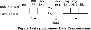 Figure 1–Asynchronous Data Transmission
When a transmitting serial device is idle (not sending data), it maintains the transmission line in a continuous state (“mark” in Figure 1). The transmitting device may begin sending a character at any time by sending a start bit. The start bit tells the receiving device to prepare to receive a character. The transmitting device then transmits 5, 6, 7, or 8 data bits, optionally followed by a parity bit. The value of the parity bit is chosen such that the number of 1’s among the data and parity bits is even or odd, depending on whether the parity is even or odd, respectively. Finally, the transmitting device sends 1, 1.5, or 2 stop bits, indicating the end of the character. The measure of the total number of bits sent over the transmission line per second is called the baud rate.
If a parity bit is set incorrectly, the receiving device will note a parity error. The time elapsed from the start bit to the last stop bit is called a frame. If the receiving device doesn’t get a stop bit after the data and parity bits, it will note a framing error. After the stop bits, the transmitting device may send another character or maintain the line in the mark state. If the line is held in the “space” state (Figure 1) for one frame or longer, a break occurs. Breaks are used to interrupt data transmission.
_______________________________________________________________________________
»ABOUT THE SERIAL DRIVERS
_______________________________________________________________________________
Note: The extensions to the Serial Drivers described in this chapter were
originally documented in Inside Macintosh, Volumes IV. As such, the
Volume IV information refers to the 128K ROM and System file version
3.2 and later. The sections of this chapter that cover these extensions
are so noted.
There are two Macintosh device drivers for serial communication: the RAM Serial Driver and the ROM Serial Driver. The two drivers are nearly identical, although the RAM driver has a few features the ROM driver doesn’t. Both allow Macintosh applications to communicate with serial devices via the two serial ports on the back of the Macintosh.
Note: There are actually two versions of the RAM Serial Driver; one is for
the Macintosh 128K and 512K, the other is for the Macintosh XL. If you
want your application to run on all versions of the Macintosh, you
should install both drivers in your application resource file, as
resources of type 'SERD'. The resource ID should be 1 for the Macintosh
128K and 512K driver, and 2 for the Macintosh XL driver.
Each Serial Driver actually consists of four drivers: one input driver and one output driver for the modem port, and one input driver and one output driver for the printer port (Figure 2). Each input driver receives data via a serial port and transfers it to the application. Each output driver takes data from the application and sends it out through a serial port. The input and output drivers for a port are closely related, and share some of the same routines. Each driver does, however, have a separate device control entry, which allows the Serial Drivers to support full-duplex communication. An individual port can both transmit and receive data at the same time. The serial ports are controlled by the Macintosh’s Zilog Z8530 Serial Communications Controller
(SCC). Channel A of the SCC controls the modem port, and channel B controls the printer port.
Data received via a serial port passes through a three-character buffer in the SCC and then into a buffer in the input driver for the port. Characters are removed from the input driver’s buffer each time an application issues a Read call to the driver. Each input driver’s buffer can initially hold up to 64 characters, but your application can specify a larger buffer if necessary. The following errors may occur:
• If the SCC buffer ever overflows (because the input driver doesn’t read
it often enough), a hardware overrun error occurs.
• If an input driver’s buffer ever overflows (because the application
doesn’t issue Read calls to the driver often enough), a software overrun
error occurs.
The printer port should be used for output-only connections to devices such as printers, or at low baud rates (300 baud or less). The modem port has no such restrictions. It may be used simultaneously with disk accesses without fear of hardware overrun errors, because whenever the Disk Driver must turn off interrupts for longer than 100 microseconds, it stores any data received via the modem port and later passes the data to the modem port’s input driver.
Figure 1–Asynchronous Data Transmission
When a transmitting serial device is idle (not sending data), it maintains the transmission line in a continuous state (“mark” in Figure 1). The transmitting device may begin sending a character at any time by sending a start bit. The start bit tells the receiving device to prepare to receive a character. The transmitting device then transmits 5, 6, 7, or 8 data bits, optionally followed by a parity bit. The value of the parity bit is chosen such that the number of 1’s among the data and parity bits is even or odd, depending on whether the parity is even or odd, respectively. Finally, the transmitting device sends 1, 1.5, or 2 stop bits, indicating the end of the character. The measure of the total number of bits sent over the transmission line per second is called the baud rate.
If a parity bit is set incorrectly, the receiving device will note a parity error. The time elapsed from the start bit to the last stop bit is called a frame. If the receiving device doesn’t get a stop bit after the data and parity bits, it will note a framing error. After the stop bits, the transmitting device may send another character or maintain the line in the mark state. If the line is held in the “space” state (Figure 1) for one frame or longer, a break occurs. Breaks are used to interrupt data transmission.
_______________________________________________________________________________
»ABOUT THE SERIAL DRIVERS
_______________________________________________________________________________
Note: The extensions to the Serial Drivers described in this chapter were
originally documented in Inside Macintosh, Volumes IV. As such, the
Volume IV information refers to the 128K ROM and System file version
3.2 and later. The sections of this chapter that cover these extensions
are so noted.
There are two Macintosh device drivers for serial communication: the RAM Serial Driver and the ROM Serial Driver. The two drivers are nearly identical, although the RAM driver has a few features the ROM driver doesn’t. Both allow Macintosh applications to communicate with serial devices via the two serial ports on the back of the Macintosh.
Note: There are actually two versions of the RAM Serial Driver; one is for
the Macintosh 128K and 512K, the other is for the Macintosh XL. If you
want your application to run on all versions of the Macintosh, you
should install both drivers in your application resource file, as
resources of type 'SERD'. The resource ID should be 1 for the Macintosh
128K and 512K driver, and 2 for the Macintosh XL driver.
Each Serial Driver actually consists of four drivers: one input driver and one output driver for the modem port, and one input driver and one output driver for the printer port (Figure 2). Each input driver receives data via a serial port and transfers it to the application. Each output driver takes data from the application and sends it out through a serial port. The input and output drivers for a port are closely related, and share some of the same routines. Each driver does, however, have a separate device control entry, which allows the Serial Drivers to support full-duplex communication. An individual port can both transmit and receive data at the same time. The serial ports are controlled by the Macintosh’s Zilog Z8530 Serial Communications Controller
(SCC). Channel A of the SCC controls the modem port, and channel B controls the printer port.
Data received via a serial port passes through a three-character buffer in the SCC and then into a buffer in the input driver for the port. Characters are removed from the input driver’s buffer each time an application issues a Read call to the driver. Each input driver’s buffer can initially hold up to 64 characters, but your application can specify a larger buffer if necessary. The following errors may occur:
• If the SCC buffer ever overflows (because the input driver doesn’t read
it often enough), a hardware overrun error occurs.
• If an input driver’s buffer ever overflows (because the application
doesn’t issue Read calls to the driver often enough), a software overrun
error occurs.
The printer port should be used for output-only connections to devices such as printers, or at low baud rates (300 baud or less). The modem port has no such restrictions. It may be used simultaneously with disk accesses without fear of hardware overrun errors, because whenever the Disk Driver must turn off interrupts for longer than 100 microseconds, it stores any data received via the modem port and later passes the data to the modem port’s input driver.
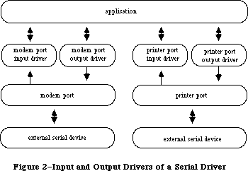 Figure 2–Input and Output Drivers of a Serial Driver
All four drivers default to 9600 baud, eight data bits per character, no parity bit, and two stop bits. You can change any of these options. The Serial Drivers support Clear To Send (CTS) hardware handshake and XOn/XOff software flow control.
Note: The ROM Serial Driver defaults to hardware handshake only; it doesn’t
support XOn/XOff input flow control—only output flow control. Use the
RAM Serial Driver if you want XOn/XOff input flow control. The RAM
Serial Driver defaults to no hardware handshake and no software flow
control.
Whenever an input driver receives a break, it terminates any pending Read requests, but not Write requests. You can choose to have the input drivers terminate Read requests whenever a parity, overrun, or framing error occurs.
Note: The ROM Serial Driver always terminates input requests when an error
occurs. Use the RAM Serial Driver if you don’t want input requests to
be terminated by errors.
You can request the Serial Drivers to post device driver events whenever a change in the hardware handshake status or a break occurs, if you want your application to take some specific action upon these occurrences.
Note: The extensions to the Serial Drivers described in the following
paragraphs were originally documented in Inside Macintosh, Volume IV.
As such, this information refers to the 128K ROMs and System file
version 3.2 and later.
In the 128K ROM, a single new Serial Driver replaces the RAM and ROM Serial Drivers.
Note: The new Serial Driver has a version number of 2. The old ROM driver
had a version number of 0, and the old RAM driver a version number of 1.
For best results, include the RAM Serial Drivers as resources of type 'SERD' in the resource fork of your application and continue to use RAMSDOpen and RAMSDClose. If the 128K ROM is present, the new driver is automatically substituted.
The new Serial Driver verifies that the serial port is correctly configured and free; if not, the result code portNotCf or portInUse is returned. When opened, the Serial Driver defaults to hardware handshake on (as did the old ROM driver).
Note: The Q & A Stack “Programming” section contains a thorough discussion
of configuration errors.
The Data Terminal Ready (DTR) line in the RS232 interface is now automatically asserted when the Serial Driver is opened; DTR is negated when it is closed. Control calls let you explicitly set the state of this line, as well as use it to automatically control the input data flow from an external device.
New advanced control calls let you control the DTR line, set certain control options, and modify the translation of parity error default characters; they’re described below.
All control and status calls may be immediate. (For information about immediate calls, see the Device Manager chapter.)
The following bugs have been fixed:
• The procedure RAMSDClose preserves mouse interrupts during its execution.
• The execution of break and close routines is now synchronized to the
current transmission.
• Incoming clock pulses on the CTS line are now detected; if they’re present,
CTS interrupts are disabled.
• If you open only the input channel of a driver, the Open routine checks
to see if the necessary variables have been initialized and exits if they
have not.
_______________________________________________________________________________
»USING THE SERIAL DRIVERS
_______________________________________________________________________________
Note: The information on Using the Serial Drivers described in the following
paragraphs was originally documented in Inside Macintosh, Volume II.
This section introduces you to the Serial Driver routines described in detail in the next section, and discusses other calls you can make to communicate with the Serial Drivers.
Drivers are referred to by name and reference number:
Driver Driver name Reference number
Modem port input .AIn –6
Modem port output .AOut –7
Printer port input .BIn –8
Printer port output .BOut –9
Warning: You should not hard-code Reference numbers; instead, use the
Device Manager to open the driver, then use the Reference numbers
that it returns.
Before you can receive data through a port, both the input and output drivers for the port must be opened. Before you can send data through a port, the output driver for the port must be opened. To open the ROM input and output drivers, call the Device Manager Open function; to open the RAM input and output drivers, call the Serial Driver function RAMSDOpen. The RAM drivers occupy less than 2K bytes of memory in the application heap.
When you open an output driver, the Serial Driver initializes local variables for the output driver and the associated input driver, allocates and locks buffer storage for both drivers, installs interrupt handlers for both drivers, and initializes the correct SCC channel (ROM Serial Driver only). When you open an input driver, the Serial Driver only notes the location of its device control entry.
You shouldn’t ever close the ROM Serial Driver with a Device Manager Close call. If you wish to replace it with a RAM Serial Driver, the RAMSDOpen call will automatically close the ROM driver for you. You must close the RAM Serial Driver with a call to RAMSDClose before your application terminates; this will also release the memory occupied by the driver itself. When you close an output driver, the Serial Driver resets the appropriate SCC channel, releases all local variable and buffer storage space, and restores any changed interrupt vectors.
Warning: The previous paragraph applies to all Macintosh models through the
Macintosh Plus. Closing the serial driver on these machines kills
mouse interrupts, since quadrature signals go to the SCC.
Note: The Q & A Stack “Programming” section and Macintosh Technical Note #249
contain a thorough discussion of opening and closing the ROM serial
driver.
X-Ref: Technical Note #249
To transmit serial data out through a port, make a Device Manager Write call to the output driver for the port. You must pass the following parameters:
• the driver reference number –7 or –9, depending on whether you’re using
the modem port or the printer port
• a buffer that contains the data you want to transmit
• the number of bytes you want to transmit
To receive serial data from a port, make a Device Manager Read call to the input driver for the port. You must pass the following parameters:
• the driver reference number –6 or –8, depending on whether you’re using
the modem port or the printer port
• a buffer to receive the data
• the number of bytes you want to receive
There are six different calls you can make to the Serial Driver’s control routine:
• KillIO causes all current I/O requests to be aborted and any bytes
remaining in both input buffers to be discarded. KillIO is a Device
Manager call.
• SerReset resets and reinitializes a driver with new data bits, stop bits,
parity bit, and baud rate information.
• SerSetBuf allows you to specify a new input buffer, replacing the driver’s
64-character default buffer.
• SerHShake allows you to specify handshake options.
• SerSetBrk sets break mode.
• SerClrBrk clears break mode.
Advanced programmers can make nine additional calls to the RAM Serial Driver’s control routine on 64K ROM machines and 14 additional calls on 128K ROM machines; see the “Advanced Control Calls” section.
There are two different calls you can make to the Serial Driver’s status routine:
• SerGetBuf returns the number of bytes in the buffer of an input driver.
• SerStatus returns information about errors, I/O requests, and handshake.
Assembly-language note: Control and Status calls to the RAM Serial Driver may
be immediate (use IMMED as the second argument to the
routine macro).
_______________________________________________________________________________
»SERIAL DRIVER ROUTINES
_______________________________________________________________________________
Most of the Serial Driver routines return an integer result code of type OSErr; each routine description lists all of the applicable result codes.
_______________________________________________________________________________
»Opening and Closing the RAM Serial Driver
FUNCTION RAMSDOpen (whichPort: SPortSel) : OSErr; [Not in ROM]
RAMSDOpen closes the ROM Serial Driver and opens the RAM input and output drivers for the port identified by the whichPort parameter, which must be a member of the SPortSel set:
TYPE SPortSel = (sPortA, {modem port}
sPortB {printer port});
RAMSDOpen determines what type of Macintosh is in use and chooses the RAM Serial Driver appropriate to that machine.
Assembly-language note: To open the RAM input and output drivers from assembly
language, call this Pascal procedure from your program.
Result codes noErr No error
openErr Can’t open driver
PROCEDURE RAMSDClose (whichPort: SPortSel); [Not in ROM]
RAMSDClose closes the RAM input and output drivers for the port identified by the whichPort parameter, which must be a member of the SPortSel set (defined in the description of RAMSDOpen above).
Warning: The RAM Serial Driver must be closed with a call to RAMSDClose
before your application terminates.
Assembly-language note: To close the RAM input and output drivers from
assembly language, call this Pascal procedure from
your program.
_______________________________________________________________________________
»Changing Serial Driver Information
FUNCTION SerReset (refNum: INTEGER; serConfig: INTEGER) : OSErr;
[Not in ROM]
Assembly-language note: SerReset is equivalent to a Control call with
csCode=8 and csParam=serConfig.
SerReset resets and reinitializes the input or output driver having the reference number refNum according to the information in serConfig. Figure 3 shows the format of serConfig.
Figure 2–Input and Output Drivers of a Serial Driver
All four drivers default to 9600 baud, eight data bits per character, no parity bit, and two stop bits. You can change any of these options. The Serial Drivers support Clear To Send (CTS) hardware handshake and XOn/XOff software flow control.
Note: The ROM Serial Driver defaults to hardware handshake only; it doesn’t
support XOn/XOff input flow control—only output flow control. Use the
RAM Serial Driver if you want XOn/XOff input flow control. The RAM
Serial Driver defaults to no hardware handshake and no software flow
control.
Whenever an input driver receives a break, it terminates any pending Read requests, but not Write requests. You can choose to have the input drivers terminate Read requests whenever a parity, overrun, or framing error occurs.
Note: The ROM Serial Driver always terminates input requests when an error
occurs. Use the RAM Serial Driver if you don’t want input requests to
be terminated by errors.
You can request the Serial Drivers to post device driver events whenever a change in the hardware handshake status or a break occurs, if you want your application to take some specific action upon these occurrences.
Note: The extensions to the Serial Drivers described in the following
paragraphs were originally documented in Inside Macintosh, Volume IV.
As such, this information refers to the 128K ROMs and System file
version 3.2 and later.
In the 128K ROM, a single new Serial Driver replaces the RAM and ROM Serial Drivers.
Note: The new Serial Driver has a version number of 2. The old ROM driver
had a version number of 0, and the old RAM driver a version number of 1.
For best results, include the RAM Serial Drivers as resources of type 'SERD' in the resource fork of your application and continue to use RAMSDOpen and RAMSDClose. If the 128K ROM is present, the new driver is automatically substituted.
The new Serial Driver verifies that the serial port is correctly configured and free; if not, the result code portNotCf or portInUse is returned. When opened, the Serial Driver defaults to hardware handshake on (as did the old ROM driver).
Note: The Q & A Stack “Programming” section contains a thorough discussion
of configuration errors.
The Data Terminal Ready (DTR) line in the RS232 interface is now automatically asserted when the Serial Driver is opened; DTR is negated when it is closed. Control calls let you explicitly set the state of this line, as well as use it to automatically control the input data flow from an external device.
New advanced control calls let you control the DTR line, set certain control options, and modify the translation of parity error default characters; they’re described below.
All control and status calls may be immediate. (For information about immediate calls, see the Device Manager chapter.)
The following bugs have been fixed:
• The procedure RAMSDClose preserves mouse interrupts during its execution.
• The execution of break and close routines is now synchronized to the
current transmission.
• Incoming clock pulses on the CTS line are now detected; if they’re present,
CTS interrupts are disabled.
• If you open only the input channel of a driver, the Open routine checks
to see if the necessary variables have been initialized and exits if they
have not.
_______________________________________________________________________________
»USING THE SERIAL DRIVERS
_______________________________________________________________________________
Note: The information on Using the Serial Drivers described in the following
paragraphs was originally documented in Inside Macintosh, Volume II.
This section introduces you to the Serial Driver routines described in detail in the next section, and discusses other calls you can make to communicate with the Serial Drivers.
Drivers are referred to by name and reference number:
Driver Driver name Reference number
Modem port input .AIn –6
Modem port output .AOut –7
Printer port input .BIn –8
Printer port output .BOut –9
Warning: You should not hard-code Reference numbers; instead, use the
Device Manager to open the driver, then use the Reference numbers
that it returns.
Before you can receive data through a port, both the input and output drivers for the port must be opened. Before you can send data through a port, the output driver for the port must be opened. To open the ROM input and output drivers, call the Device Manager Open function; to open the RAM input and output drivers, call the Serial Driver function RAMSDOpen. The RAM drivers occupy less than 2K bytes of memory in the application heap.
When you open an output driver, the Serial Driver initializes local variables for the output driver and the associated input driver, allocates and locks buffer storage for both drivers, installs interrupt handlers for both drivers, and initializes the correct SCC channel (ROM Serial Driver only). When you open an input driver, the Serial Driver only notes the location of its device control entry.
You shouldn’t ever close the ROM Serial Driver with a Device Manager Close call. If you wish to replace it with a RAM Serial Driver, the RAMSDOpen call will automatically close the ROM driver for you. You must close the RAM Serial Driver with a call to RAMSDClose before your application terminates; this will also release the memory occupied by the driver itself. When you close an output driver, the Serial Driver resets the appropriate SCC channel, releases all local variable and buffer storage space, and restores any changed interrupt vectors.
Warning: The previous paragraph applies to all Macintosh models through the
Macintosh Plus. Closing the serial driver on these machines kills
mouse interrupts, since quadrature signals go to the SCC.
Note: The Q & A Stack “Programming” section and Macintosh Technical Note #249
contain a thorough discussion of opening and closing the ROM serial
driver.
X-Ref: Technical Note #249
To transmit serial data out through a port, make a Device Manager Write call to the output driver for the port. You must pass the following parameters:
• the driver reference number –7 or –9, depending on whether you’re using
the modem port or the printer port
• a buffer that contains the data you want to transmit
• the number of bytes you want to transmit
To receive serial data from a port, make a Device Manager Read call to the input driver for the port. You must pass the following parameters:
• the driver reference number –6 or –8, depending on whether you’re using
the modem port or the printer port
• a buffer to receive the data
• the number of bytes you want to receive
There are six different calls you can make to the Serial Driver’s control routine:
• KillIO causes all current I/O requests to be aborted and any bytes
remaining in both input buffers to be discarded. KillIO is a Device
Manager call.
• SerReset resets and reinitializes a driver with new data bits, stop bits,
parity bit, and baud rate information.
• SerSetBuf allows you to specify a new input buffer, replacing the driver’s
64-character default buffer.
• SerHShake allows you to specify handshake options.
• SerSetBrk sets break mode.
• SerClrBrk clears break mode.
Advanced programmers can make nine additional calls to the RAM Serial Driver’s control routine on 64K ROM machines and 14 additional calls on 128K ROM machines; see the “Advanced Control Calls” section.
There are two different calls you can make to the Serial Driver’s status routine:
• SerGetBuf returns the number of bytes in the buffer of an input driver.
• SerStatus returns information about errors, I/O requests, and handshake.
Assembly-language note: Control and Status calls to the RAM Serial Driver may
be immediate (use IMMED as the second argument to the
routine macro).
_______________________________________________________________________________
»SERIAL DRIVER ROUTINES
_______________________________________________________________________________
Most of the Serial Driver routines return an integer result code of type OSErr; each routine description lists all of the applicable result codes.
_______________________________________________________________________________
»Opening and Closing the RAM Serial Driver
FUNCTION RAMSDOpen (whichPort: SPortSel) : OSErr; [Not in ROM]
RAMSDOpen closes the ROM Serial Driver and opens the RAM input and output drivers for the port identified by the whichPort parameter, which must be a member of the SPortSel set:
TYPE SPortSel = (sPortA, {modem port}
sPortB {printer port});
RAMSDOpen determines what type of Macintosh is in use and chooses the RAM Serial Driver appropriate to that machine.
Assembly-language note: To open the RAM input and output drivers from assembly
language, call this Pascal procedure from your program.
Result codes noErr No error
openErr Can’t open driver
PROCEDURE RAMSDClose (whichPort: SPortSel); [Not in ROM]
RAMSDClose closes the RAM input and output drivers for the port identified by the whichPort parameter, which must be a member of the SPortSel set (defined in the description of RAMSDOpen above).
Warning: The RAM Serial Driver must be closed with a call to RAMSDClose
before your application terminates.
Assembly-language note: To close the RAM input and output drivers from
assembly language, call this Pascal procedure from
your program.
_______________________________________________________________________________
»Changing Serial Driver Information
FUNCTION SerReset (refNum: INTEGER; serConfig: INTEGER) : OSErr;
[Not in ROM]
Assembly-language note: SerReset is equivalent to a Control call with
csCode=8 and csParam=serConfig.
SerReset resets and reinitializes the input or output driver having the reference number refNum according to the information in serConfig. Figure 3 shows the format of serConfig.
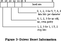 Figure 3–Driver Reset Information
You can use the following predefined constants to set the values of various bits of serConfig:
CONST baud300 = 380; {300 baud}
baud600 = 189; {600 baud}
baud1200 = 94; {1200 baud}
baud1800 = 62; {1800 baud}
baud2400 = 46; {2400 baud}
baud3600 = 30; {3600 baud}
baud4800 = 22; {4800 baud}
baud7200 = 14; {7200 baud}
baud9600 = 10; {9600 baud}
baud19200 = 4; {19200 baud}
baud57600 = 0; {57600 baud}
stop10 = 16384; {1 stop bit}
stop15 = -32768; {1.5 stop bits}
stop20 = -16384; {2 stop bits}
noParity = 0; {no parity}
oddParity = 4096; {odd parity}
evenParity = 12288; {even parity}
data5 = 0; {5 data bits}
data6 = 2048; {6 data bits}
data7 = 1024; {7 data bits}
data8 = 3072; {8 data bits}
For example, the default setting of 9600 baud, eight data bits, two stop bits, and no parity bit is equivalent to passing the following value in serConfig: baud9600 + data8 + stop20 + noParity.
Result codes noErr No error
Note: The Q & A Stack “Programming” section contains updated information
on the 38,400 baud setting.
FUNCTION SerSetBuf (refNum: INTEGER; serBPtr: Ptr;
serBLen: INTEGER) : OSErr; [Not in ROM]
Assembly-language note: SerSetBuf is equivalent to a Control call with
csCode=9, csParam=serBPtr, and csParam+4=serBLen.
SerSetBuf specifies a new input buffer for the input driver having the reference number refNum. SerBPtr points to the buffer, and serBLen specifies the number of bytes in the buffer. To restore the driver’s default buffer, call SerSetBuf with serBLen set to 0.
Warning: You must lock a new input buffer while it’s in use.
Result codes noErr No error
FUNCTION SerHShake (refNum: INTEGER; flags: SerShk) : OSErr; [Not in ROM]
Assembly-language note: SerHShake is equivalent to a Control call with
csCode=10 and csParam through csParam+6 flags.
SerHShake sets handshake options and other control information, as specified by the flags parameter, for the input or output driver having the reference number refNum. The flags parameter has the following data structure:
TYPE SerShk = PACKED RECORD
fXOn: Byte; {XOn/XOff output flow control flag}
fCTS: Byte; {CTS hardware handshake flag}
xOn: CHAR; {XOn character}
xOff: CHAR; {XOff character}
errs: Byte; {errors that cause abort}
evts: Byte; {status changes that cause events}
fInX: Byte; {XOn/XOff input flow control flag}
null: Byte {not used}
END;
If fXOn is nonzero, XOn/XOff output flow control is enabled; if fInX is nonzero, XOn/XOff input flow control is enabled. XOn and xOff specify the XOn character and XOff character used for XOn/XOff flow control. If fCTS is nonzero, CTS hardware handshake is enabled. The errs field indicates which errors will cause input requests to be aborted; for each type of error, there’s a predefined constant in which the corresponding bit is set:
CONST parityErr = 16; {set if parity error}
hwOverrunErr = 32; {set if hardware overrun error}
framingErr = 64; {set if framing error}
Note: The ROM Serial Driver doesn’t support XOn/XOff input flow control or
aborts caused by error conditions.
The evts field indicates whether changes in the CTS or break status will cause the Serial Driver to post device driver events. You can use the following predefined constants to set or test the value of evts:
CONST ctsEvent = 32; {set if CTS change will cause event to be posted}
breakEvent = 128; {set if break status change will cause event }
{ to be posted}
Warning: Use of this option is discouraged because of the long time that
interrupts are disabled while such an event is posted.
Result codes noErr No error
X-Ref: Technical Note #56
FUNCTION SerSetBrk (refNum: INTEGER) : OSErr; [Not in ROM]
Assembly-language note: SerSetBrk is equivalent to a Control call with
csCode=12.
SerSetBrk sets break mode in the input or output driver having the reference number refNum.
Result codes noErr No error
FUNCTION SerClrBrk (refNum: INTEGER) : OSErr; [Not in ROM]
Assembly-language note: SerClrBrk is equivalent to a Control call with
csCode=11.
SerClrBrk clears break mode in the input or output driver having the reference number refNum.
Result codes noErr No error
_______________________________________________________________________________
»Getting Serial Driver Information
FUNCTION SerGetBuf (refNum: INTEGER; VAR count: LONGINT) : OSErr;
[Not in ROM]
Assembly-language note: SerGetBuf is equivalent to a Status call with
csCode=2; count is returned in csParam as a long word.
SerGetBuf returns, in the count parameter, the number of bytes in the buffer of the input driver having the reference number refNum.
Result codes noErr No error
FUNCTION SerStatus (refNum: INTEGER; VAR serSta: SerStaRec) : OSErr;
[Not in ROM]
Assembly-language note: SerStatus is equivalent to a Status call with
csCode=8; serSta is returned in csParam through
csParam+5.
SerStatus returns in serSta three words of status information for the input or output driver having the reference number refNum. SerSta has the following data structure:
TYPE SerStaRec = PACKED RECORD
cumErrs: Byte; {cumulative errors}
xOffSent: Byte; {XOff sent as input flow control}
rdPend: Byte; {read pending flag}
wrPend: Byte; {write pending flag}
ctsHold: Byte; {CTS flow control hold flag}
xOffHold: Byte {XOff flow control hold flag}
END;
CumErrs indicates which errors have occurred since the last time SerStatus was called:
CONST swOverrunErr = 1; {set if software overrun error}
parityErr = 16; {set if parity error}
hwOverrunErr = 32; {set if hardware overrun error}
framingErr = 64; {set if framing error}
If the driver has sent an XOff character, xOffSent will be equal to the following predefined constant:
CONST xOffWasSent = $80; {XOff character was sent}
If the driver has a Read or Write call pending, rdPend or wrPend, respectively, will be nonzero. If output has been suspended because the hardware handshake was disabled, ctsHold will be nonzero. If output has been suspended because an XOff character was received, xOffHold will be nonzero.
Result codes noErr No error
_______________________________________________________________________________
»ADVANCED CONTROL CALLS
_______________________________________________________________________________
This section describes several advanced control calls. Control calls to the Serial Driver should be made to the output character channel driver.
csCode = 13 csParam = baudRate
This call provides an additional way (besides SerReset) to set the baud rate. CsParam specifies the actual baud rate as an integer (for instance, 9600). The closest baud rate that the Serial Driver will generate is returned in csParam.
csCode = 19 csParam = char
After this call is made, all incoming characters with parity errors will be replaced by the character specified by the ASCII code in csParam. If csParam is 0, no character replacement will be done.
csCode = 21
This call unconditionally sets XOff for output flow control. It’s equivalent to receiving an XOff character. Data transmission is halted until an XOn is received or a Control call with csCode=24 is made.
csCode = 22
This call unconditionally clears XOff for output flow control. It’s equivalent to receiving an XOn character.
csCode = 23
This call sends an XOn character for input flow control if the last input flow control character sent was XOff.
csCode = 24
This call unconditionally sends an XOn character for input flow control, regardless of the current state of input flow control.
csCode = 25
This call sends an XOff character for input flow control if the last input flow control character sent was XOn.
csCode = 26
This call unconditionally sends an XOff character for input flow control, regardless of the current state of input flow control.
csCode = 27
This call lets you reset the SCC channel belonging to the driver specified by ioRefNum before calling RAMSDClose or SerReset.
Note: The extensions to the Serial Drivers described in the following
paragraphs were originally documented in Inside Macintosh, Volume IV.
As such, this information refers to the 128K ROMs and System file
version 3.2 and later.
csCode = 14 csParam through csParam+7 = serShk
This call is identical to a control call with csCode=10 (the SerHShake function, described above) with the additional specification of the DTR handshake option in the eighth byte of its flags parameter (the null field of the SerShk record). You can enable DTR input flow control by setting this byte to a nonzero value. This works symmetrically to hardware handshake output control.
csCode = 16 csParam = byte
This call sets miscellaneous control options. Bits 0–6 should be set to 0 for future options. Bit 7, if set to 1, will cause DTR to be left unchanged when the driver is closed (rather than the normal procedure of negating DTR). This may be used for modem control to prevent the modem from hanging up just because the driver is being closed (such as when the user temporarily exits the terminal program).
csCode = 17
This call asserts DTR.
csCode = 18
This call negates DTR.
csCode = 20 csParam = char csParam+1 = alt char
This call is an extension of call 19, which would simply clear bit 7 of an incoming character when it matched the replacement character. After this call is made, all incoming characters with parity errors will be replaced by the character specified by the ASCII code in csParam. If csParam is 0, no character replacement will be done. If an incoming character is the same as the replacement character specified in csParam, it will be replaced instead by the second character specified in csParam+1.
Note: With this call, the null character (ASCII $00) can be used as the
alternate character but not as the first replacement.
_______________________________________________________________________________
»SUMMARY OF THE SERIAL DRIVERS
_______________________________________________________________________________
Constants
CONST
{ Driver reset information }
baud300 = 380; {300 baud}
baud600 = 189; {600 baud}
baud1200 = 94; {1200 baud}
baud1800 = 62; {1800 baud}
baud2400 = 46; {2400 baud}
baud3600 = 30; {3600 baud}
baud4800 = 22; {4800 baud}
baud7200 = 14; {7200 baud}
baud9600 = 10; {9600 baud}
baud19200 = 4; {19200 baud}
baud57600 = 0; {57600 baud}
stop10 = 16384; {1 stop bit}
stop15 = -32768; {1.5 stop bits}
stop20 = -16384; {2 stop bits}
noParity = 0; {no parity}
oddParity = 4096; {odd parity}
evenParity = 12288; {even parity}
data5 = 0; {5 data bits}
data6 = 2048; {6 data bits}
data7 = 1024; {7 data bits}
data8 = 3072; {8 data bits}
{ Masks for errors }
swOverrunErr = 1; {set if software overrun error}
parityErr = 16; {set if parity error}
hwOverrunErr = 32; {set if hardware overrun error}
framingErr = 64; {set if framing error}
{ Masks for changes that cause events to be posted }
ctsEvent = 32; {set if CTS change will cause event to be posted}
breakEvent = 128; {set if break status change will cause }
{ event to be posted}
{ Indication that DTR is negated }
dtrNegated = $40; {[Volume IV addition]}
{ Indication that an XOff character was sent }
xOffWasSent = $80;
{ Result codes }
noErr = 0; {no error}
openErr = -23; {attempt to open RAM Serial Driver failed}
{ Result codes [Volume IV additions]}
portInUse = -97; {driver Open error, port already in use}
portNotCf = -98; {driver Open error, port not configured for this }
{ connection}
memFullErr = –108; {not enough room in heap zone}
_______________________________________________________________________________
Data Types
TYPE
SPortSel = (sPortA, {modem port}
sPortB {printer port});
SerStaRec = PACKED RECORD
cumErrs: Byte; {cumulative errors}
xOffSent: Byte; {XOff sent as input flow control}
rdPend: Byte; {read pending flag}
wrPend: Byte; {write pending flag}
ctsHold: Byte; {CTS flow control hold flag}
xOffHold: Byte {XOff flow control hold flag}
END;
SerShk = PACKED RECORD
fXOn: Byte; {XOn/XOff output flow control flag}
fCTS: Byte; {CTS hardware handshake flag}
xOn: CHAR; {XOn character}
xOff: CHAR; {XOff character}
errs: Byte; {errors that cause abort}
evts: Byte; {status changes that cause events}
fInX: Byte; {XOn/XOff input flow control flag}
null: Byte {not used}
END;
{[Volume IV addition]}
SerShk = PACKED RECORD
fXOn: Byte; {XOn/XOff output flow control flag}
fCTS: Byte; {CTS hardware handshake flag}
xOn: CHAR; {XOn character}
xOff: CHAR; {XOff character}
errs: Byte; {errors that cause abort}
evts: Byte; {status changes that cause events}
fInX: Byte; {XOn/XOff input flow control flag}
fDTR: Byte {DTR input flow control flag}
END;
_______________________________________________________________________________
Routines
Opening and Closing the RAM Serial Driver
FUNCTION RAMSDOpen (whichPort: SPortSel) : OSErr;
PROCEDURE RAMSDClose (whichPort: SPortSel);
Changing Serial Driver Information
FUNCTION SerReset (refNum: INTEGER; serConfig: INTEGER) : OSErr;
FUNCTION SerSetBuf (refNum: INTEGER; serBPtr: Ptr;
serBLen: INTEGER) : OSErr;
FUNCTION SerHShake (refNum: INTEGER; flags: SerShk) : OSErr;
FUNCTION SerSetBrk (refNum: INTEGER) : OSErr;
FUNCTION SerClrBrk (refNum: INTEGER) : OSErr;
Getting Serial Driver Information
FUNCTION SerGetBuf (refNum: INTEGER; VAR count: LONGINT) : OSErr;
FUNCTION SerStatus (refNum: INTEGER; VAR serSta: SerStaRec) : OSErr;
_______________________________________________________________________________
Advanced Control Calls (RAM Serial Driver)
csCode csParam Effect
13 baudRate Set baud rate (actual rate, as an integer)
19 char Replace parity errors
21 Unconditionally set XOff for output flow control
22 Unconditionally clear XOff for input flow control
23 Send XOn for input flow control if XOff was sent last
24 Unconditionally send XOn for input flow control
25 Send XOff for input flow control if XOn was sent last
26 Unconditionally send XOff for input flow control
27 Reset SCC channel
Volume IV additions
csCode csParam Effect
14 serShk Set handshake parameters
16 byte Set miscellaneous control options
17 Asserts DTR
18 Negates DTR
20 2 chars Replace parity errors, with alternate
replacement character
_______________________________________________________________________________
Driver Names and Reference Numbers
Driver Driver name Reference number
Modem port input .AIn –6
Modem port output .AOut –7
Printer port input .BIn –8
Printer port output .BOut –9
_______________________________________________________________________________
Assembly-Language Information
Constants
; Result codes
noErr .EQU 0 ;no error
openErr .EQU –23 ;attempt to open RAM Serial Driver failed
; [Volume IV additions]
portInUse .EQU -97 ;driver Open error, port already in use
portNotCf .EQU -98 ;driver Open error, port not configured
;for this connection
memFullErr EQU –108 ;not enough room in heap zone
Structure of Status Information for SerStatus
ssCumErrs Cumulative errors (byte)
ssXOffSent XOff sent as input flow control (byte)
ssRdPend Read pending flag (byte)
ssWrPend Write pending flag (byte)
ssCTSHold CTS flow control hold flag (byte)
ssXOffHold XOff flow control hold flag (byte)
Structure of Control Information for SerHShake
shFXOn XOn/XOff output flow control flag (byte)
shFCTS CTS hardware handshake flag (byte)
shXOn XOn character (byte)
shXOff XOff character (byte)
shErrs Errors that cause abort (byte)
shEvts Status changes that cause events (byte)
shFInX XOn/XOff input flow control flag (byte)
shDTR DTR control flag (byte) [Volume IV addition]
Equivalent Device Manager Calls
Pascal routine Call
SerReset Control with csCode=8, csParam=serConfig
SerSetBuf Control with csCode=8, csParam=serBPtr, csParam+4=serBLen
SerHShake Control with csCode=10, csParam through csParam+6=flags
SerSetBrk Control with csCode=12
SerClrBrk Control with csCode=11
SerGetBuf Status with csCode=2; count returned in csParam
SerStatus Status with csCode=8; serSta returned in csParam
through csParam+5
Further Reference:
_______________________________________________________________________________
Resource Manager
Toolbox Event Manager
Memory Manager
Device Manager
Technical Note #2, Compatibility Guidelines
Technical Note #10, Pinouts
Technical Note #56, Break/CTS Device Driver Event Structure
Technical Note #65, Macintosh Plus Pinouts
Technical Note #117, Compatibility: Why & How
Technical Note #212, The Joy Of Being 32-Bit Clean
Technical Note #249, Opening the Serial Driver
Q & A Stack
“Macintosh Family Hardware Reference”
Figure 3–Driver Reset Information
You can use the following predefined constants to set the values of various bits of serConfig:
CONST baud300 = 380; {300 baud}
baud600 = 189; {600 baud}
baud1200 = 94; {1200 baud}
baud1800 = 62; {1800 baud}
baud2400 = 46; {2400 baud}
baud3600 = 30; {3600 baud}
baud4800 = 22; {4800 baud}
baud7200 = 14; {7200 baud}
baud9600 = 10; {9600 baud}
baud19200 = 4; {19200 baud}
baud57600 = 0; {57600 baud}
stop10 = 16384; {1 stop bit}
stop15 = -32768; {1.5 stop bits}
stop20 = -16384; {2 stop bits}
noParity = 0; {no parity}
oddParity = 4096; {odd parity}
evenParity = 12288; {even parity}
data5 = 0; {5 data bits}
data6 = 2048; {6 data bits}
data7 = 1024; {7 data bits}
data8 = 3072; {8 data bits}
For example, the default setting of 9600 baud, eight data bits, two stop bits, and no parity bit is equivalent to passing the following value in serConfig: baud9600 + data8 + stop20 + noParity.
Result codes noErr No error
Note: The Q & A Stack “Programming” section contains updated information
on the 38,400 baud setting.
FUNCTION SerSetBuf (refNum: INTEGER; serBPtr: Ptr;
serBLen: INTEGER) : OSErr; [Not in ROM]
Assembly-language note: SerSetBuf is equivalent to a Control call with
csCode=9, csParam=serBPtr, and csParam+4=serBLen.
SerSetBuf specifies a new input buffer for the input driver having the reference number refNum. SerBPtr points to the buffer, and serBLen specifies the number of bytes in the buffer. To restore the driver’s default buffer, call SerSetBuf with serBLen set to 0.
Warning: You must lock a new input buffer while it’s in use.
Result codes noErr No error
FUNCTION SerHShake (refNum: INTEGER; flags: SerShk) : OSErr; [Not in ROM]
Assembly-language note: SerHShake is equivalent to a Control call with
csCode=10 and csParam through csParam+6 flags.
SerHShake sets handshake options and other control information, as specified by the flags parameter, for the input or output driver having the reference number refNum. The flags parameter has the following data structure:
TYPE SerShk = PACKED RECORD
fXOn: Byte; {XOn/XOff output flow control flag}
fCTS: Byte; {CTS hardware handshake flag}
xOn: CHAR; {XOn character}
xOff: CHAR; {XOff character}
errs: Byte; {errors that cause abort}
evts: Byte; {status changes that cause events}
fInX: Byte; {XOn/XOff input flow control flag}
null: Byte {not used}
END;
If fXOn is nonzero, XOn/XOff output flow control is enabled; if fInX is nonzero, XOn/XOff input flow control is enabled. XOn and xOff specify the XOn character and XOff character used for XOn/XOff flow control. If fCTS is nonzero, CTS hardware handshake is enabled. The errs field indicates which errors will cause input requests to be aborted; for each type of error, there’s a predefined constant in which the corresponding bit is set:
CONST parityErr = 16; {set if parity error}
hwOverrunErr = 32; {set if hardware overrun error}
framingErr = 64; {set if framing error}
Note: The ROM Serial Driver doesn’t support XOn/XOff input flow control or
aborts caused by error conditions.
The evts field indicates whether changes in the CTS or break status will cause the Serial Driver to post device driver events. You can use the following predefined constants to set or test the value of evts:
CONST ctsEvent = 32; {set if CTS change will cause event to be posted}
breakEvent = 128; {set if break status change will cause event }
{ to be posted}
Warning: Use of this option is discouraged because of the long time that
interrupts are disabled while such an event is posted.
Result codes noErr No error
X-Ref: Technical Note #56
FUNCTION SerSetBrk (refNum: INTEGER) : OSErr; [Not in ROM]
Assembly-language note: SerSetBrk is equivalent to a Control call with
csCode=12.
SerSetBrk sets break mode in the input or output driver having the reference number refNum.
Result codes noErr No error
FUNCTION SerClrBrk (refNum: INTEGER) : OSErr; [Not in ROM]
Assembly-language note: SerClrBrk is equivalent to a Control call with
csCode=11.
SerClrBrk clears break mode in the input or output driver having the reference number refNum.
Result codes noErr No error
_______________________________________________________________________________
»Getting Serial Driver Information
FUNCTION SerGetBuf (refNum: INTEGER; VAR count: LONGINT) : OSErr;
[Not in ROM]
Assembly-language note: SerGetBuf is equivalent to a Status call with
csCode=2; count is returned in csParam as a long word.
SerGetBuf returns, in the count parameter, the number of bytes in the buffer of the input driver having the reference number refNum.
Result codes noErr No error
FUNCTION SerStatus (refNum: INTEGER; VAR serSta: SerStaRec) : OSErr;
[Not in ROM]
Assembly-language note: SerStatus is equivalent to a Status call with
csCode=8; serSta is returned in csParam through
csParam+5.
SerStatus returns in serSta three words of status information for the input or output driver having the reference number refNum. SerSta has the following data structure:
TYPE SerStaRec = PACKED RECORD
cumErrs: Byte; {cumulative errors}
xOffSent: Byte; {XOff sent as input flow control}
rdPend: Byte; {read pending flag}
wrPend: Byte; {write pending flag}
ctsHold: Byte; {CTS flow control hold flag}
xOffHold: Byte {XOff flow control hold flag}
END;
CumErrs indicates which errors have occurred since the last time SerStatus was called:
CONST swOverrunErr = 1; {set if software overrun error}
parityErr = 16; {set if parity error}
hwOverrunErr = 32; {set if hardware overrun error}
framingErr = 64; {set if framing error}
If the driver has sent an XOff character, xOffSent will be equal to the following predefined constant:
CONST xOffWasSent = $80; {XOff character was sent}
If the driver has a Read or Write call pending, rdPend or wrPend, respectively, will be nonzero. If output has been suspended because the hardware handshake was disabled, ctsHold will be nonzero. If output has been suspended because an XOff character was received, xOffHold will be nonzero.
Result codes noErr No error
_______________________________________________________________________________
»ADVANCED CONTROL CALLS
_______________________________________________________________________________
This section describes several advanced control calls. Control calls to the Serial Driver should be made to the output character channel driver.
csCode = 13 csParam = baudRate
This call provides an additional way (besides SerReset) to set the baud rate. CsParam specifies the actual baud rate as an integer (for instance, 9600). The closest baud rate that the Serial Driver will generate is returned in csParam.
csCode = 19 csParam = char
After this call is made, all incoming characters with parity errors will be replaced by the character specified by the ASCII code in csParam. If csParam is 0, no character replacement will be done.
csCode = 21
This call unconditionally sets XOff for output flow control. It’s equivalent to receiving an XOff character. Data transmission is halted until an XOn is received or a Control call with csCode=24 is made.
csCode = 22
This call unconditionally clears XOff for output flow control. It’s equivalent to receiving an XOn character.
csCode = 23
This call sends an XOn character for input flow control if the last input flow control character sent was XOff.
csCode = 24
This call unconditionally sends an XOn character for input flow control, regardless of the current state of input flow control.
csCode = 25
This call sends an XOff character for input flow control if the last input flow control character sent was XOn.
csCode = 26
This call unconditionally sends an XOff character for input flow control, regardless of the current state of input flow control.
csCode = 27
This call lets you reset the SCC channel belonging to the driver specified by ioRefNum before calling RAMSDClose or SerReset.
Note: The extensions to the Serial Drivers described in the following
paragraphs were originally documented in Inside Macintosh, Volume IV.
As such, this information refers to the 128K ROMs and System file
version 3.2 and later.
csCode = 14 csParam through csParam+7 = serShk
This call is identical to a control call with csCode=10 (the SerHShake function, described above) with the additional specification of the DTR handshake option in the eighth byte of its flags parameter (the null field of the SerShk record). You can enable DTR input flow control by setting this byte to a nonzero value. This works symmetrically to hardware handshake output control.
csCode = 16 csParam = byte
This call sets miscellaneous control options. Bits 0–6 should be set to 0 for future options. Bit 7, if set to 1, will cause DTR to be left unchanged when the driver is closed (rather than the normal procedure of negating DTR). This may be used for modem control to prevent the modem from hanging up just because the driver is being closed (such as when the user temporarily exits the terminal program).
csCode = 17
This call asserts DTR.
csCode = 18
This call negates DTR.
csCode = 20 csParam = char csParam+1 = alt char
This call is an extension of call 19, which would simply clear bit 7 of an incoming character when it matched the replacement character. After this call is made, all incoming characters with parity errors will be replaced by the character specified by the ASCII code in csParam. If csParam is 0, no character replacement will be done. If an incoming character is the same as the replacement character specified in csParam, it will be replaced instead by the second character specified in csParam+1.
Note: With this call, the null character (ASCII $00) can be used as the
alternate character but not as the first replacement.
_______________________________________________________________________________
»SUMMARY OF THE SERIAL DRIVERS
_______________________________________________________________________________
Constants
CONST
{ Driver reset information }
baud300 = 380; {300 baud}
baud600 = 189; {600 baud}
baud1200 = 94; {1200 baud}
baud1800 = 62; {1800 baud}
baud2400 = 46; {2400 baud}
baud3600 = 30; {3600 baud}
baud4800 = 22; {4800 baud}
baud7200 = 14; {7200 baud}
baud9600 = 10; {9600 baud}
baud19200 = 4; {19200 baud}
baud57600 = 0; {57600 baud}
stop10 = 16384; {1 stop bit}
stop15 = -32768; {1.5 stop bits}
stop20 = -16384; {2 stop bits}
noParity = 0; {no parity}
oddParity = 4096; {odd parity}
evenParity = 12288; {even parity}
data5 = 0; {5 data bits}
data6 = 2048; {6 data bits}
data7 = 1024; {7 data bits}
data8 = 3072; {8 data bits}
{ Masks for errors }
swOverrunErr = 1; {set if software overrun error}
parityErr = 16; {set if parity error}
hwOverrunErr = 32; {set if hardware overrun error}
framingErr = 64; {set if framing error}
{ Masks for changes that cause events to be posted }
ctsEvent = 32; {set if CTS change will cause event to be posted}
breakEvent = 128; {set if break status change will cause }
{ event to be posted}
{ Indication that DTR is negated }
dtrNegated = $40; {[Volume IV addition]}
{ Indication that an XOff character was sent }
xOffWasSent = $80;
{ Result codes }
noErr = 0; {no error}
openErr = -23; {attempt to open RAM Serial Driver failed}
{ Result codes [Volume IV additions]}
portInUse = -97; {driver Open error, port already in use}
portNotCf = -98; {driver Open error, port not configured for this }
{ connection}
memFullErr = –108; {not enough room in heap zone}
_______________________________________________________________________________
Data Types
TYPE
SPortSel = (sPortA, {modem port}
sPortB {printer port});
SerStaRec = PACKED RECORD
cumErrs: Byte; {cumulative errors}
xOffSent: Byte; {XOff sent as input flow control}
rdPend: Byte; {read pending flag}
wrPend: Byte; {write pending flag}
ctsHold: Byte; {CTS flow control hold flag}
xOffHold: Byte {XOff flow control hold flag}
END;
SerShk = PACKED RECORD
fXOn: Byte; {XOn/XOff output flow control flag}
fCTS: Byte; {CTS hardware handshake flag}
xOn: CHAR; {XOn character}
xOff: CHAR; {XOff character}
errs: Byte; {errors that cause abort}
evts: Byte; {status changes that cause events}
fInX: Byte; {XOn/XOff input flow control flag}
null: Byte {not used}
END;
{[Volume IV addition]}
SerShk = PACKED RECORD
fXOn: Byte; {XOn/XOff output flow control flag}
fCTS: Byte; {CTS hardware handshake flag}
xOn: CHAR; {XOn character}
xOff: CHAR; {XOff character}
errs: Byte; {errors that cause abort}
evts: Byte; {status changes that cause events}
fInX: Byte; {XOn/XOff input flow control flag}
fDTR: Byte {DTR input flow control flag}
END;
_______________________________________________________________________________
Routines
Opening and Closing the RAM Serial Driver
FUNCTION RAMSDOpen (whichPort: SPortSel) : OSErr;
PROCEDURE RAMSDClose (whichPort: SPortSel);
Changing Serial Driver Information
FUNCTION SerReset (refNum: INTEGER; serConfig: INTEGER) : OSErr;
FUNCTION SerSetBuf (refNum: INTEGER; serBPtr: Ptr;
serBLen: INTEGER) : OSErr;
FUNCTION SerHShake (refNum: INTEGER; flags: SerShk) : OSErr;
FUNCTION SerSetBrk (refNum: INTEGER) : OSErr;
FUNCTION SerClrBrk (refNum: INTEGER) : OSErr;
Getting Serial Driver Information
FUNCTION SerGetBuf (refNum: INTEGER; VAR count: LONGINT) : OSErr;
FUNCTION SerStatus (refNum: INTEGER; VAR serSta: SerStaRec) : OSErr;
_______________________________________________________________________________
Advanced Control Calls (RAM Serial Driver)
csCode csParam Effect
13 baudRate Set baud rate (actual rate, as an integer)
19 char Replace parity errors
21 Unconditionally set XOff for output flow control
22 Unconditionally clear XOff for input flow control
23 Send XOn for input flow control if XOff was sent last
24 Unconditionally send XOn for input flow control
25 Send XOff for input flow control if XOn was sent last
26 Unconditionally send XOff for input flow control
27 Reset SCC channel
Volume IV additions
csCode csParam Effect
14 serShk Set handshake parameters
16 byte Set miscellaneous control options
17 Asserts DTR
18 Negates DTR
20 2 chars Replace parity errors, with alternate
replacement character
_______________________________________________________________________________
Driver Names and Reference Numbers
Driver Driver name Reference number
Modem port input .AIn –6
Modem port output .AOut –7
Printer port input .BIn –8
Printer port output .BOut –9
_______________________________________________________________________________
Assembly-Language Information
Constants
; Result codes
noErr .EQU 0 ;no error
openErr .EQU –23 ;attempt to open RAM Serial Driver failed
; [Volume IV additions]
portInUse .EQU -97 ;driver Open error, port already in use
portNotCf .EQU -98 ;driver Open error, port not configured
;for this connection
memFullErr EQU –108 ;not enough room in heap zone
Structure of Status Information for SerStatus
ssCumErrs Cumulative errors (byte)
ssXOffSent XOff sent as input flow control (byte)
ssRdPend Read pending flag (byte)
ssWrPend Write pending flag (byte)
ssCTSHold CTS flow control hold flag (byte)
ssXOffHold XOff flow control hold flag (byte)
Structure of Control Information for SerHShake
shFXOn XOn/XOff output flow control flag (byte)
shFCTS CTS hardware handshake flag (byte)
shXOn XOn character (byte)
shXOff XOff character (byte)
shErrs Errors that cause abort (byte)
shEvts Status changes that cause events (byte)
shFInX XOn/XOff input flow control flag (byte)
shDTR DTR control flag (byte) [Volume IV addition]
Equivalent Device Manager Calls
Pascal routine Call
SerReset Control with csCode=8, csParam=serConfig
SerSetBuf Control with csCode=8, csParam=serBPtr, csParam+4=serBLen
SerHShake Control with csCode=10, csParam through csParam+6=flags
SerSetBrk Control with csCode=12
SerClrBrk Control with csCode=11
SerGetBuf Status with csCode=2; count returned in csParam
SerStatus Status with csCode=8; serSta returned in csParam
through csParam+5
Further Reference:
_______________________________________________________________________________
Resource Manager
Toolbox Event Manager
Memory Manager
Device Manager
Technical Note #2, Compatibility Guidelines
Technical Note #10, Pinouts
Technical Note #56, Break/CTS Device Driver Event Structure
Technical Note #65, Macintosh Plus Pinouts
Technical Note #117, Compatibility: Why & How
Technical Note #212, The Joy Of Being 32-Bit Clean
Technical Note #249, Opening the Serial Driver
Q & A Stack
“Macintosh Family Hardware Reference”
The Shutdown Manager
_______________________________________________________________________________
THE SHUTDOWN MANAGER
_______________________________________________________________________________
About This Chapter
About the Shutdown Manager
Using the Shutdown Manager
Shutdown Manager Routines
Summary of the Shutdown Manager
_______________________________________________________________________________
»ABOUT THIS CHAPTER
_______________________________________________________________________________
This chapter describes the Shutdown Manager, which gives applications a chance to perform any necessary housekeeping before the machine is rebooted or turned off. The Shutdown Manager also provides the user with a consistent interface for restarting and turning off the different versions of the Macintosh.
_______________________________________________________________________________
»ABOUT THE SHUTDOWN MANAGER
_______________________________________________________________________________
With earlier versions of the System file, the Shut Down (a misnomer) menu item in the Special menu resulted in the restarting of the machine. There was no way to turn the machine off from software; the user needed to choose Shut Down and manually toggle the power switch before the machine had begun to reboot.
On the Macintosh II, two options are available: the Restart menu item results in a reboot, while the Shut Down menu item actually turns off power to the machine.
The Macintosh SE does not have power-off capability from software. When the user chooses Restart, the machine is rebooted. When the user chooses Shut Down, the Shutdown Manager blackens the screen and calls the System Error Handler with an error code of 42. This causes an alert to be presented, telling the user it’s safe to turn off the machine.
The Shutdown Manager is contained in the System Resource File (System file version 3.3 or later) and is compatible with all earlier versions of the Macintosh. If the Shutdown Manager is present and the user chooses Restart, the machine is rebooted. On all earlier machines (with the exception of the Macintosh XL), if the user chooses Shut Down, the Shutdown alert is presented. On the Macintosh XL, Shut Down fades the screen and turns off the power.
_______________________________________________________________________________
»USING THE SHUTDOWN MANAGER
_______________________________________________________________________________
The ShutDwnPower procedure turns the machine off; if the Macintosh must be turned off manually, the Shutdown alert is presented to the user. The ShutDwnStart procedure causes the machine to reboot.
Warning: ShutDwnPower and ShutDwnStart are used by the Finder and other
system software; your application should have no need to call these
two routines.
Both ShutDwnPower and ShutDwnStart check to see if Switcher is running; if it is, the ExitToShell procedure is called, exiting Switcher and returning control to the Finder. Otherwise, they perform standard system housekeeping prior to reboot or power off; this housekeeping can be divided into two phases. In the first phase, the unit table is searched for open drivers (including desk accessories). For each driver, if the dNeedGoodbye bit in the drvrFlags field is set (see the Device Manager chapter for details), a Control call with csCode equal to –1 is sent to the driver’s control routine. Then, the UnloadScrap function is called, writing the desk scrap to the disk.
Note: While the Finder does not currently read the scrap at boot time, it
may do so in the future.
In the second phase of housekeeping, the volume-control-block queue is searched; for each mounted volume, the UnmountVol and Eject routines are called.
The ShutDwnInstall procedure lets you install your own shutdown procedure(s) prior to either of these two system housekeeping phases, as well as just prior to rebooting and/or power off. The ShutDwnRemove procedure lets you remove your shutdown procedures.
_______________________________________________________________________________
»SHUTDOWN MANAGER ROUTINES
_______________________________________________________________________________
Assembly-language note: You can invoke each of the Shutdown Manager routines
with a macro that has the same name as the routine
preceded by an underscore. These macros expand to
invoke the _Shutdown trap macro. The _Shutdown trap
determines which routine to execute from a routine
selector, an integer that’s passed to it in a word on
the stack. The routine selectors are as follows:
sdPowerOff .EQU 1
sdRestart .EQU 2
sdInstall .EQU 3
sdRemove .EQU 4
PROCEDURE ShutDwnPower;
ShutDwnPower performs system housekeeping, executes any shutdown procedures you may have installed with ShutDwnInstall, and turns the machine off. (If the machine must be turned off manually, the shutdown alert is presented.)
PROCEDURE ShutDwnStart;
ShutDwnPower performs system housekeeping, executes any shutdown procedures you may have installed with ShutDwnInstall, and reboots the machine.
Assembly-language note: ShutDwnStart results in the execution of the Reset
instruction, followed by a jump to the ROM boot code
(the address is the value of the global variable
ROMBase + 10).
PROCEDURE ShutDwnInstall (shutDwnProc: ProcPtr; flags: INTEGER);
ShutDwnInstall installs the shutdown procedure pointed to by shutDwnProc. The flags parameter indicates where in the shutdown process to execute your shutdown procedure. The following masks are provided for setting the bits of the flags parameter:
CONST sdOnPowerOff = 1; {call procedure before power off}
sdOnRestart = 2; {call procedure before restart}
sdOnUnmount = 4; {call procedure before unmounting}
sdOnDrivers = 8; {call procedure before closing drivers}
sdRestartOrPower = sdOnPowerOff + sdOnRestart {call procedure before }
{ either power off or restart}
PROCEDURE ShutDwnRemove (shutDwnProc: ProcPtr);
ShutDwnRemove removes the shutdown procedure pointed to by shutDwnProc.
Note: If the procedure was marked for execution at a number of points in the
shutdown process (say, for instance, at unmounting, restart, and power
off), it will be removed at all points.
_______________________________________________________________________________
»SUMMARY OF THE SHUTDOWN MANAGER
_______________________________________________________________________________
Constants
CONST
{ Masks for ShutDwnInstall procedure }
sdOnPowerOff = 1; {call procedure before power off}
sdOnRestart = 2; {call procedure before restart}
sdOnUnmount = 4; {call procedure before unmounting}
sdOnDrivers = 8; {call procedure before closing drivers}
sdRestartOrPower = sdOnPowerOff + sdOnRestart; {call procedure before }
{ either power off or restart}
_______________________________________________________________________________
Routines
PROCEDURE ShutDwnPower;
PROCEDURE ShutDwnStart;
PROCEDURE ShutDwnInstall (shutDwnProc: ProcPtr; flags: INTEGER);
PROCEDURE ShutDwnRemove (shutDwnProc: ProcPtr);
_______________________________________________________________________________
Assembly-Language Information
Constants
; Masks for ShutDwnInstall procedure
sdOnPowerOff .EQU 1 ;call procedure before power off
sdOnRestart .EQU 2 ;call procedure before restart
sdOnUnmount .EQU 4 ;call procedure before unmounting
sdOnDrivers .EQU 8 ;call procedure before closing drivers
sdRestartOrPower .EQU sdOnPowerOff + sdOnRestart ;call procedure before
; either power off or restart
; Routine selectors
; (Note: You can invoke each of the Shutdown Manager routines with
; a macro that has the same name as the routine preceded by an
; underscore.)
sdPowerOff .EQU 1
sdRestart .EQU 2
sdInstall .EQU 3
sdRemove .EQU 4
Trap Macro Name
_Shutdown
(Note: You can invoke each of the Shutdown Manager routines with a macro that
has the same name as the routine preceded by an underscore. Also, be
aware that the _Shutdown macro is not in ROM.)
The Slot Manager
_______________________________________________________________________________
THE SLOT MANAGER
_______________________________________________________________________________
About This Chapter
Slot Card Firmware
Slot Manager Routines
Data Types
Slot Parameter Block
SExec Block
Principal Slot Manager Routines
Specialized Slot Manager Routines
Advanced Slot Manager Routines
Status Results
Fatal Errors
Nonfatal Errors
Summary of the Slot Manager
_______________________________________________________________________________
»ABOUT THIS CHAPTER
_______________________________________________________________________________
Warning: This chapter has not been updated to reflect changes and improvements
that are available on systems using 32-Bit QuickDraw. For further
information on 32-Bit QuickDraw, please refer to the 32-Bit QuickDraw
documentation (available on “Phil & Dave’s Excellent CD: The Release
Version).
This chapter describes the Slot Manager section of the Macintosh II ROM. The Slot Manager contains routines that let your program identify cards plugged into NuBus slots in the Macintosh II and communicate with the firmware on each card.
Note: The Macintosh SE computer also has slots, but they work differently.
For an explanation of Macintosh SE slots, see the book “Designing Cards
and Drivers for Macintosh II and Macintosh SE.”
Reader’s guide: You need the information in this chapter only if you are
writing an application, driver, or operating system that
must access a slot card directly. Otherwise, the standard
Macintosh Toolbox and Operating System routines normally
take care of all slot card management, making the Slot
Manager transparent to most applications.
The Slot Manager routines described in this chapter are divided into three sections:
• The section “Principal Slot Manager Routines” describes routines that you
might need if you are writing an application or a driver.
• The section “Specialized Slot Manager Routines” describes routines that
you might need if you are writing a driver.
• The section “Advanced Slot Manager Routines” describes routines that are
normally used only by the operating system. This section is included for
completeness of documentation.
Note: When accessing NuBus cards directly, it is important that you use the
standard Slot Manager routines. If you try to bypass them, your
application may conflict with other applications and probably will not
work in future Apple computers.
Before trying to use the information in this chapter, you should already be familiar with the Device Manager. If you are writing a driver, you should also be familiar with
• the information in the book “Designing Cards and Drivers for Macintosh II
and Macintosh SE”
• the architecture and mode of operation of the specific card or cards your
driver will access
_______________________________________________________________________________
»SLOT CARD FIRMWARE
_______________________________________________________________________________
Most of the routines described in this chapter let you access data or code structures residing in the firmware of all NuBus plug-in cards. These structures are described in detail in the book “Designing Cards and Drivers for Macintosh II and Macintosh SE.” They have certain uniform features that create a standard interface to the Slot Manager. The principal card firmware structures are the following:
• A format block, containing format and identification information for the
card’s firmware and an offset to its sResource directory
• An sResource directory, containing an identification number and offset
for each sResource list in the firmware
• A Board sResource list, containing information about the slot card itself
• One or more other sResource lists, each of which contains information
about a single sResource in the card’s firmware
Don’t confuse sResources on plug-in cards with standard Macintosh resources; they are different, although related conceptually. Every sResource has a type and a name. It may also have an icon and driver code in firmware, and may define a region of system memory allocated to the card it is in. Such sResources are treated like devices. Some sResources, however, may contain only data—for example, special fonts. You must understand the specific nature of an sResource before trying to access it with the Slot Manager.
The physical location of a slot card’s firmware is called its declaration ROM. The Slot Manager maintains a table, called the Slot Resource Table, of all sResources currently available in the system.
For full details about slot card firmware, see the book “Designing Cards and Drivers for Macintosh II and Macintosh SE.”
_______________________________________________________________________________
»SLOT MANAGER ROUTINES
_______________________________________________________________________________
The Slot Manager is a section of the Macintosh II ROM containing routines that communicate with NuBus card firmware. This section discusses them under three headings:
• the four principal routines—those used by virtually any driver or
application that needs to manage a NuBus card directly
• the specialized routines—those that might be used by a driver
• the advanced routines—those normally used only by the Macintosh II
operating system
Assembly-language note: You can invoke each of the Slot Manager routines
with a macro of the same name preceded by an
underscore. These macros, however, aren’t trap macros
themselves; instead they expand to invoke the trap
macro _SlotManager. The Slot Manager then determines
the routine to execute from the routine selector, a
long integer that’s passed in register D0. The
routine selectors are the following:
SReadByte EQU 0
SReadWord EQU 1
SReadLong EQU 2
SGetCString EQU 3
SGetBlock EQU 5
SFindStruct EQU 6
SReadStruct EQU 7
SReadInfo EQU 16
SReadPRAMRec EQU 17
SPutPRAMRec EQU 18
SReadFHeader EQU 19
SNextRsrc EQU 20
SNextTypesRsrc EQU 21
SRsrcInfo EQU 22
SCkCardStatus EQU 24
SReadDrvrName EQU 25
SFindDevBase EQU 27
InitSDeclMgr EQU 32
SPrimaryInit EQU 33
SCardChanged EQU 34
SExec EQU 35
SOffsetData EQU 36
InitPRAMRecs EQU 37
SReadPBSize EQU 38
SCalcStep EQU 40
InitsRsrcTable EQU 41
SSearchSRT EQU 42
SUpdateSRT EQU 43
SCalcsPointer EQU 44
SGetDriver EQU 45
SPtrToSlot EQU 46
SFindsInfoRecPtr EQU 47
SFindsRsrcPtr EQU 48
SdeleteSRTRec EQU 49
At the time the trap macro is called, register A0
must contain a pointer to the Slot Parameter Block,
described in the next section. On exit, the routine
leaves a result code in register D0.
_______________________________________________________________________________
»Data Types
The following data types are used for communication with the Slot Manager routines:
Data type Description
Byte 8 bits, signed or unsigned
Word 16 bits, signed or unsigned
Long 32 bits, signed or unsigned
cString One-dimensional array of bytes, the last of which
has the value $00
sBlock Data structure starting with a 4-byte header
that gives the total sBlock size
The bit formats of the word, long, and sBlock data types are shown in Figure 1.
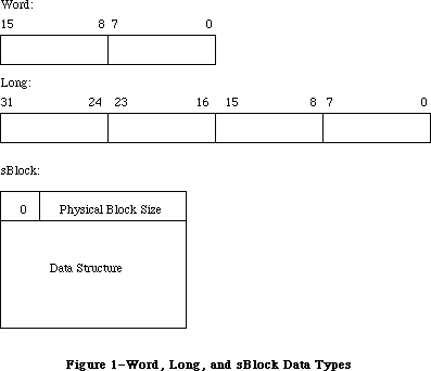 Figure 1–Word, Long, and sBlock Data Types
Note: Pointers are always of type long. The value of a null
pointer is $00000000.
_______________________________________________________________________________
»Slot Parameter Block
Data transfer between the Slot Manager and card firmware takes place through the Slot Parameter Block, which has this structure:
TYPE
SpBlockPtr = ^SpBlock;
SpBlock = PACKED RECORD
spResult: LONGINT; {FUNCTION result used by }
{ every function}
spsPointer: Ptr; {structure pointer}
spSize: LONGINT; {size of structure}
spOffsetData: LONGINT; {offset/data field used by }
{ sOffsetData}
spIOFileName: Ptr; {pointer to IOFile name used }
{ by sDisDrvrName}
spsExecPBlk: Ptr; {pointer to sExec parameter block}
spStackPtr: Ptr; {old Stack pointer}
spMisc: LONGINT; {misc field for SDM}
spReserved: LONGINT; {reserved for future }
{ expansion}
spIOReserved: INTEGER; {reserved field of Slot }
{ Resource Table}
spRefNum: INTEGER; {RefNum}
spCategory: INTEGER; {sType:Category}
spCType: INTEGER; {sType:Type}
spDrvrSW: INTEGER; {sType:DrvrSW}
spDrvrHW: INTEGER; {sType:DrvrHW}
spTBMask: SignedByte; {type bit mask (Bits 0..3 }
{ mask words 0..3}
spSlot: SignedByte; {slot number}
spID: SignedByte; {structure ID}
spExtDev: SignedByte; {ID of the external device}
spHWDev: SignedByte; {ID of the hardware device}
spByteLanes: SignedByte; {ByteLanes from format block }
{ in card ROM}
spFlags: SignedByte; {standard flags}
spKey: SignedByte; {internal use only}
END;
Assembly-language note: The Slot Parameter Block has the following structure
in assembly language:
spResult Function result (long)
spsPointer Structure pointer (long)
spOffsetData Offset/Data field (long)
spIOFileName Pointer to IOFileName (long)
spsExecBlk Pointer to sExec parameter block (long)
spStackPtr Old stack pointer (long)
spMisc Reserved for Slot Manager (long)
spReserved Reserved (long)
spIOReserved Reserved field of Slot Resource
Table (word)
spRefNum Slot Resource Table reference
number (word)
spCategory sResource type: Category (word)
spType sResource type: Type (word)
spDrvrSW sResource type: Driver software
identifier (word)
spDrvrHW sResource type: Driver hardware
identifier (word)
spTBMask Type bit mask (byte)
spSlot Slot number (byte)
spId sResource list ID (byte)
spExtDev External device identifier (byte)
spHWDev Hardware device identifier (byte)
spByteLanes ByteLanes value from format block
in card firmware (byte)
spFlags Standard flags (byte)
spKey Reserved (byte)
spBlockSize Size of Slot Parameter Block
_______________________________________________________________________________
»SExec Block
For the routine sExec, data transfer between the Slot Manager and card firmware also takes place through the SExec Block, which has this structure:
SEBlockPtr = ^SEBlock;
SEBlock = PACKED RECORD
seSlot: SignedByte; {slot number}
sesRsrcId: SignedByte; {sResource Id}
seStatus: INTEGER; {status of code executed by sExec}
seFlags: SignedByte; {flags}
seFiller0: SignedByte; {filler--SignedByte to align }
{ on word boundary}
seFiller1: SignedByte; {filler}
seFiller2: SignedByte; {filler}
seResult: LONGINT; {result of sLoad}
seIOFileName: LONGINT; {pointer to IOFile name}
seDevice: SignedByte; {which device to read from}
sePartition: SignedByte; {the partition}
seOSType: SignedByte; {type of OS}
seReserved: SignedByte; {reserved field}
seRefNum: SignedByte; {RefNum of the driver}
seNumDevices: SignedByte; {number of devices to load}
seBootState: SignedByte; {state of StartBoot code}
END;
Assembly-language note: The SExec Block has the following structure in
assembly language:
seSlot Slot number (byte)
sesRsrcId sResource list ID (byte)
seStatus Status of code executed by sExec (word)
seFlags Flags (byte)
seFiller0 Filler (byte)
seFiller1 Filler (byte)
seFiller2 Filler (byte)
seResult Result of sLoad (long)
seIOFileName Pointer to IOFile name (long)
seDevice Which device to read from (byte)
sePartition Device partition (byte)
seOSType Operating system type (byte)
seReserved Reserved (byte)
seRefNum RefNum of the driver (byte)
seNumDevices Number of devices to load (byte)
seBootState Status of the StartBoot code (byte)
The seOSType parameter has these values:
Name Value Description
sMacOS68000 1 Load routine will run on a Macintosh
computer with MC68000 processor
sMacOS68020 2 Load routine will run on a Macintosh
computer with MC68020 processor
Other values may be used for future Macintosh family operating systems.
_______________________________________________________________________________
»Principal Slot Manager Routines
The routines described in this section are available to drivers and applications that need to perform slot management tasks beyond those automatically provided by the system. Their principal purpose is to find slot devices and open their drivers.
The description of each Slot Manager routine specifies which parameters are required for communication with the routine. A right-pointing arrow indicates that the parameter is an input to the routine; a left-pointing arrow indicates that it is an output. Other parameters whose values may be affected by the routine are also listed. Parameters not mentioned remain unchanged.
Assembly-language note: All Slot Manager routines return a status result in
the low-order word of register D0 after execution. A
D0 value of zero indicates successful execution. Other
D0 values are listed under “Status Results” later in
this section. All routines report fatal errors (those
that halt program execution); some may also report
nonfatal errors. The description of each routine
specifies if it can return status values indicating
nonfatal errors.
FUNCTION SRsrcInfo(spBlkPtr: SpBlockPtr) : OSErr;
Trap macro: _SRsrcInfo
Required Parameters
<-- spsPointer
<-- spIOReserved
<-- spRefNum
<-- spCategory
<-- spCType
<-- spDrvrSW
<-- spDrvrHW
--> spSlot
--> spId
--> spExtDev
<-- spHWDev
The trap macro SRsrcInfo returns an sResource list pointer (spsPointer), plus the sResource type (category, cType, software, and hardware), driver reference number (spRefNum), and Slot Resource Table ioReserved field (spIOReserved) for the sResource specified by the slot number spSlot, sResource list identification number spId, and external device identifier spExtDev. This call is most often used to return the driver reference number.
FUNCTION SNextsRsrc(spBlkPtr: SpBlockPtr) : OSErr;
Trap macro: _SNextsRsrc
Required Parameters
<-> spSlot
<-> spId
<-> spExtDev
<-- spsPointer
<-- spRefNum
<-- spIOReserved
<-- spCategory
<-- spCType
<-- spDrvrSW
<-- spDrvrHW
<-- spHWDev
Starting from a given slot number spSlot, sResource list identification number spId, and external device identifier spExtDev, the trap macro SNextsRsrc returns the slot number, sResource list identification number, sResource type
(category, cType, software, and hardware), driver reference number (spRefNum), and Slot Resource Table ioReserved field (spIOReserved) for the next sResource. If there are no more sResources, SNextsRsrc returns a nonfatal error status. This routine can be used to determine the set of all sResources in a given slot card or NuBus configuration.
FUNCTION SNextTypesRsrc(spBlkPtr: SpBlockPtr) : OSErr;
Trap macro: _SNextTypesRsrc
Required Parameters
<-> spSlot
<-> spId
<-> spExtDev
--> spTBMask
<-- spsPointer
<-- spRefNum
<-- spIOReserved
<-> spCategory
<-> spCType
<-> spDrvrSW
<-> spDrvrHW
<-> spHWDev
Given an sResource type (category, cType, software, and hardware) and spTBMask, and starting from a given slot number spSlot and sResource list identification number spId, the trap macro SNextTypesRsrc returns the slot number spSlot, sResource list identification number spId, sResource type, driver reference number (spRefNum), and Slot Resource Table ioReserved field (spIOReserved) for the next sResource of that type, as masked. If there are no more sResources of that type, SNextTypesRsrc returns a nonfatal error report.
The spTBMask field lets you mask off specific fields of the sResource type that you don’t care about, by setting any of bits 0–3. Bit 3 masks off the spCategory field; bit 2 the spCType field; bit 1 the spDrvrSW field; and bit 0 the spDrvrHW field.
This procedure behaves the same as sNextsRsrc except that it returns information only about sResources of the specified type.
FUNCTION SReadDrvrName(spBlkPtr: SpBlockPtr) : OSErr;
Trap macro: _SReadDrvrName
Required Parameters
--> spSlot
--> spId
--> spResult
Other Parameters Affected
spSize
spsPointer
The trap macro SReadDrvrName reads the name of the sResource corresponding to the slot number spSlot and sResource list identification number spId, prefixes a period to the value of the cString and converts its type to Str255. It then reads the result into a Pascal string variable declared by the calling program and pointed to by spResult. The final driver name is compatible with the Open routine.
_______________________________________________________________________________
»Specialized Slot Manager Routines
The routines described in this section are used only by drivers. They find data structures in slot card firmware.
FUNCTION SReadByte(spBlkPtr: SpBlockPtr) : OSErr;
Trap macro: _SReadByte
Required Parameters
--> spsPointer
--> spId
<-- spResult
Other Parameters Affected
spOffsetData
spByteLanes
The trap macro SReadByte returns in spResult an 8-bit value identified by spId from the sResource list pointed to by spsPointer. This routine’s low-order byte can return nonfatal error reports.
FUNCTION SReadWord(spBlkPtr: SpBlockPtr) : OSErr;
Trap macro: _SReadWord
Required Parameters
--> spsPointer
--> spId
<-- spResult
Other Parameters Affected
spOffsetData
spByteLanes
The trap macro SReadWord returns in the low-order word of spResult a 16-bit value identified by spId from the sResource list pointed to by spsPointer. This routine can return nonfatal error reports.
FUNCTION sReadLong(spBlkPtr: SpBlockPtr) : OSErr;
Trap macro: _SReadLong
Required Parameters
--> spsPointer
--> spId
<-- spResult
Other Parameters Affected
spOffsetData
spByteLanes
spSize
The trap macro SReadLong returns in spResult a 32-bit value identified by spId from the sResource list pointed to by spsPointer. This routine can return nonfatal error reports.
FUNCTION SGetCString(spBlkPtr: SpBlockPtr) : OSErr;
Trap macro: _SGetCString
Required Parameters
--> spsPointer
--> spId
<-- spResult
Other Parameters Affected
spOffsetData
spByteLanes
spSize
spFlags
The trap macro SGetCString copies a cString identified by spId from the sResource list pointed to by spsPointer to a buffer pointed to by spResult. Memory for this buffer is automatically allocated by SGetCString.
FUNCTION SGetBlock(spBlkPtr: SpBlockPtr) : OSErr;
Trap macro: _SGetBlock
Required Parameters
--> spsPointer
--> spId
<-- spResult
Other Parameters Affected
spOffsetData
spByteLanes
spSize
spFlags
The trap macro SGetBlock copies the sBlock from the sResource list pointed to by spsPointer and identified by spId into a new block and returns a pointer to it in spResult. The pointer in spResult should be disposed of by using the Memory Manager routine DisposPtr.
FUNCTION SFindStruct(spBlkPtr: SpBlockPtr) : OSErr;
Trap macro: _ sFindStruct
Required Parameters
--> spId
<-> spsPointer
Other Parameters Affected
spByteLanes
The trap macro SFindStruct returns a pointer to the data structure defined by spId in the sResource list pointed to by spsPointer.
FUNCTION SReadStruct(spBlkPtr: SpBlockPtr) : OSErr;
Trap macro: _SReadStruct
Required Parameters
--> spsPointer
--> spSize
--> spResult
Other Parameter Affected
spByteLanes
The trap macro sReadStruct copies a structure of size spSize from the sResource list pointed to by spsPointer into a new block allocated by the calling program and pointed to by spResult.
FUNCTION SReadInfo(spBlkPtr: SpBlockPtr) : OSErr;
Trap macro: _SReadInfo
Required Parameters
--> spSlot
--> spResult
Other Parameter Affected
spSize
The trap macro SReadInfo reads the sInfo record identified by spSlot into a new record allocated by the calling program and pointed to by spResult. Here is the structure of the sInfo record:
TYPE
SInfoRecPtr = ^SInfoRecord;
SInfoRecord = PACKED RECORD
siDirPtr: Ptr; {pointer to directory}
siInitStatusA: INTEGER; {initialization error}
siInitStatusV: INTEGER; {status returned by }
{ vendor init code}
siState: SignedByte; {initialization state}
siCPUByteLanes: SignedByte; {0=[d0..d7], }
{ 1=[d8..d15], ...}
siTopOfROM: SignedByte; {top of ROM = $FsFFFFFx, }
{ where x is TopOfROM}
siStatusFlags: SignedByte; {bit 0--card is changed}
siTOConstant: INTEGER; {timeout constant for }
{ bus error}
siReserved: SignedByte; {reserved}
END;
Assembly-language note: The sInfo record has the following structure
in assembly language:
siDirPtr Pointer to sResource directory (long)
siInitStatusA Fundamental error (word)
siInitStatusV Status returned by vendor init
code (word)
siState Initialization state—primary,
secondary (byte)
siCPUByteLanes Each bit set signifies a byte lane
used (byte)
siTopOfROM x such that Top of ROM = $FsFFFFFx
(byte)
siStatusFlags Bit 0 indicates if card has been
changed (byte)
siTOConst Timeout constant for bus error (word)
siReserved Reserved—must be 0 (byte)
sInfoRecSize Size of sInfo record
The siDirPtr field of the sInfo record contains a pointer to the sResource directory in the configuration ROM. The siInitStatusA field indicates the result of efforts to initialize the card. A zero value indicates that the card is installed and operational. A non-zero value is the Slot Manager error code indicating why the card could not be used.
The siInitStatusV field contains the value returned by the card's primary initialization code (in the seStatus field of the seBlock). Negative values cause the card to fail initialization. Zero or positive values indicate that the card is operational.
The siState field is used internally to indicate what initialization steps have occurred so far.
The siCPUByteLanes field indicate which byte lanes are used by the card.
The siTopOfROM field gives the last nibble of the address of the actual ByteLanes value in the fHeader record.
The siStatusFlags field gives status information about the slot. Currently only the fCardIsChanged bit has meaning. A value of 1 indicates that the board ID of the installed card did not match the ID saved in parameter RAM—in other words, the card has been changed.
The siTOConstant field contains the number of retries that will be performed when a bus error occurs while accessing the declaration ROM. It defaults to 100, but may be set to another value with the TimeOut field in the board sResource of the card.
The siReserved field is reserved and should have a value of 0.
FUNCTION SReadPRAMRec(spBlkPtr: SpBlockPtr) : OSErr;
Trap macro: _SReadPRAMRec
Required Parameters
--> spSlot
--> spResult
Other Parameter Affected
spSize
The trap macro SReadPRAMRec copies the sPRAM record data for the slot identified by spSlot to a new record allocated by the calling program and pointed to by spResult.
One sPRAM record for each slot resides in the Macintosh II parameter RAM. The sPRAM record is initialized during startup by InitsPRAMRecs, described below under “Advanced Routines”. Here is its structure:
TYPE
SPRAMRecPtr = ^SPRAMRecord;
SPRAMRecord = PACKED RECORD
boardID: INTEGER; {Apple-defined card }
{ identification}
vendorUse1: SignedByte; {reserved for vendor use}
vendorUse2: SignedByte; {reserved for vendor use}
vendorUse3: SignedByte; {reserved for vendor use}
vendorUse4: SignedByte; {reserved for vendor use}
vendorUse5: SignedByte; {reserved for vendor use}
vendorUse6: SignedByte; {reserved for vendor use}
END;
Assembly-language note: The sPRAM record has the following structure in
assembly language:
boardID Apple-defined card indentification (word)
vendorUse1 Reserved for vendor use (byte)
vendorUse2 Reserved for vendor use (byte)
vendorUse3 Reserved for vendor use (byte)
vendorUse4 Reserved for vendor use (byte)
vendorUse5 Reserved for vendor use (byte)
vendorUse6 Reserved for vendor use (byte)
If a card is removed from its slot, the corresponding sPRAM record is cleared at the next system startup. If a different card is plugged back into the slot, the corresponding sPRAM record is reinitialized. A flag is set each time an sPRAM record is initialized, to alert the Start Manager.
FUNCTION SPutPRAMRec(spBlkPtr: SpBlockPtr) : OSErr;
Trap macro: _SPutPRAMRec
Required Parameters
--> spSlot
--> spsPointer
The trap macro SPutPRAMRec copies the logical data from the block referenced by spsPointer into the sPRAM record for the slot identified by spSlot. This updates the Macintosh PRAM for that slot. The sPRAM record is defined above under SReadPRAMRec. In this record, the field boardId is an Apple-defined field and is protected during execution of SPutPRAMRec.
FUNCTION SReadFHeader(spBlkPtr: SpBlockPtr) : OSErr;
Trap macro: _SReadFHeader
Required Parameters
--> spSlot
--> spResult
Other Parameters Affected
spsPointer
spByteLanes
spSize
spOffsetData
The trap macro SReadFHeader copies the format block data for the slot designated by spSlot to an FHeader record allocated by the calling program and pointed to by spResult. Here is the structure of FHeader:
TYPE
FHeaderRecPtr = ^FHeaderRec;
FHeaderRec = PACKED RECORD
fhDIROffset: LONGINT; {offset to directory}
fhLength: LONGINT; {length of ROM}
fhCRC: LONGINT; {CRC}
fhROMRev: SignedByte; {revision of ROM}
fhFormat: SignedByte; {format - 2}
fhTstPat: LONGINT; {test pattern}
fhReserved: SignedByte; {reserved}
fhByteLanes: SignedByte; {ByteLanes}
END;
Assembly-language note: The FHeader record has the following structure in
assembly language:
fhDIROffset Offset to sResource directory (long)
fhLength Length of card’s declaration ROM (long)
fhCRC Declaration ROM checksum (long)
fhROMRev ROM revision number (byte)
fhFormat ROM format number (byte)
fhTstPat Test Pattern (long)
fhReserved Reserved (byte)
fhByteLanes Byte lanes used (byte)
fhSize Size of the FHeader record
The fHeader record exists at the highest address of a card’s declaration ROM, and should therefore be visible at the highest address in the card’s slot space. The Slot Manager uses the fHeader record to verify that a card is installed in the slot, to determine its physical connection to NuBus (which byte lanes are used), and to locate the sResource directory.
The fhDIROffset field of the fHeader record is a self-relative signed 24-bit offset to the sResource directory. The high order byte must be 0, or a card initialization error occurs.
The fhLength field gives the size of the configuration ROM.
The fhCRC field gives the cyclic redundancy check (CRC) value of the declaration ROM. The CRC value itself is taken as zero in the CRC calculation.
The fhRomRev field gives the revision level of this declaration ROM. Values greater than 9 cause a card initialization error.
The fhFormat field identifies the format of the configuration ROM. Only the value 1 (appleFormat ) is currently recognized as valid.
The fhTstPat field is used to verify that the fhByteLanes field is correct.
The fhReserved field must be zero.
The fhByteLanes field indicates what NuBus byte lanes are used by the card. Byte lanes are described in the “Access to Address Space” chapter of “Designing Cards and Drivers for Macintosh II and Macintosh SE.”
FUNCTION SCkCardStatus(spBlkPtr: SpBlockPtr) : OSErr;
Trap macro: _SCkCardStatus
Required Parameter
--> spSlot
Other Parameter Affected
spResult
The trap macro SCkCardStatus checks the InitStatusA field of the sInfo record of the slot designated by spSlot, which also reflects the value of InitStatusV. If this field contains a nonzero value, SCkCardStatus returns a zero value. The sInfo record is described above under SReadInfo. The sCkCardStatus routine can return nonfatal error reports.
Trap macro: _SFindDevBase
Required Parameters
--> spSlot
--> spId
<-- spResult
The trap macro SFindDevBase returns a pointer in spResult to the base of a device whose slot number is in spSlot and whose sResource id is in spId. The base address of a device may be in either slot or superslot space but not in both. Slot or superslot slot spaces are discussed in the book “Designing Cards and Drivers for Macintosh II and Macintosh SE.”
FUNCTION SDeleteSRTRec(spBlkPtr: SpBlockPtr) : OSErr;
Trap macro: _SDeleteSRTRec
Required Parameters
--> spSlot
--> spId
--> spExtDev
The trap macro SDeleteSRTRec deletes from the system’s Slot Resource Table the sResource defined by spId,spSlot, and spExtDev.
FUNCTION SPtrToSlot(spBlkPtr: SpBlockPtr) : OSErr;
Trap macro: _SPtrToSlot
Required Parameters
--> spsPointer
<-- spSlot
The trap macro SPtrToSlot returns in spSlot the slot number of the card whose declaration ROM is pointed to by spsPointer. The value of spsPointer must have the form Fsxx xxxx, where s is a slot number.
_______________________________________________________________________________
»Advanced Slot Manager Routines
The routines described in this section are used only by the Macintosh II operating system. They are described here just for completeness of documentation.
FUNCTION InitSDeclMgr(spBlkPtr: SpBlockPtr) : OSErr;
Trap macro: _InitSDeclMgr
The trap macro InitSDeclMgr initializes the Slot Manager. The contents of the parameter block are undefined. This procedure allocates the sInfo array and checks each slot for a card. If a card is not present, an error is logged in the initStatusA field of the sInfoRecord for that slot; otherwise the card’s firmware is validated, and the resulting data is placed in the slot’s sInfoRecord. The sInfoRecord is described above under SReadInfo.
FUNCTION SPrimaryInit(spBlkPtr: SpBlockPtr) : OSErr;
Trap macro: _SPrimaryInit
Required Parameter
--> spFlags
The trap macro SPrimaryInit initializes each slot having an sPrimaryInit record. It passes the spFlags byte to the initialization code via seFlags. Within that byte the fWarmStart bit should be set to 1 if a warm start is being performed.
FUNCTION SCardChanged(spBlkPtr: SpBlockPtr) : OSErr;
Trap macro: _SCardChanged
Required Parameters
--> spSlot
<-- spResult
The trap macro SCardChanged returns a value of true in spResult if the card in slot spSlot has been changed (that is, if its sPRAMRecord has been initialized); otherwise it returns false.
FUNCTION SExec(spBlkPtr: SpBlockPtr) : OSErr;
Trap macro: _SExec
Required Parameters
--> spsPointer
--> spId
--> spsExecPBlk
Other parameters affected:
spResult
The trap macro SExec loads an sExecBlock from the sResource list pointed to by spsPointer and identified by spId to the current heap zone, checks its revision level, checks its CPU field, and executes the code. The status is returned in seStatus. The spsExecPBlk field is presumed to hold a pointer to an sExecBlock (described in the “Slot Manager Routines” section earlier in this chapter), and is passed to the sExec block code in register A0.
FUNCTION SOffsetData(spBlkPtr: SpBlockPtr) : OSErr;
Trap macro: _SOffsetData
Required Parameters
--> spsPointer
--> spId
<-- spOffsetData
<-- spByteLanes
Other Parameters Affected
spResult
spFlags
The trap macro SOffsetData returns (in spOffsetData) the contents of the
offset/data field from the sResource list identified by spId and pointed to by spsPointer. The parameter spsPointer returns a pointer to the fields’s identification number in the sResource list.
FUNCTION SReadPBSize(spBlkPtr: SpBlockPtr) : OSErr;
Trap macro: _SReadPBSize
Required Parameters
--> spsPointer
--> spId
--> spFlags
<-- spSize
<-- spByteLanes
Other Parameter Affected
spResult
The trap macro SReadPBSize reads the physical block size of the sBlock pointed to by spsPointer and identified by spId. It also checks to see that the upper byte is 0 if the fckReserved flag is set. The parameter spsPointer points to the resulting logical block when SReadPBSize is done.
FUNCTION SCalcStep(spBlkPtr: SpBlockPtr) : OSErr;
Trap macro: _SCalcStep
Parameters Required
--> spsPointer
--> spByteLanes
--> spFlags
<-- spResult
The trap macro SCalcStep calculates the field sizes in the block pointed to by spBlkPtr. It is used for stepping through the card firmware one field at a time. If the fConsecBytes flag is set it calculates the step value for consecutive bytes; otherwise it calculates it for consecutive IDs.
FUNCTION InitsRsrcTable(spBlkPtr: SpBlockPtr) : OSErr;
Trap macro: _InitsRsrcTable
The trap macro InitsRsrcTable initializes the Slot Resource Table. It scans each slot and inserts the slot, type, sRsrcId, sRsrcPtr, and HWDevID values into the table for every sResource. It sets all other fields to zero. The contents of the parameter block are undefined.
FUNCTION InitPRAMRecs(spBlkPtr: SpBlockPtr) : OSErr;
Trap macro: _InitPRAMRecs
The trap macro InitPRAMRecs scans every slot and checks its BoardId value against the value stored for it in its sPRAM record. If the values do not match, then the CardIsChanged flag is set and the Board sResource list is searched for an sPRAMInitRecord. If one is found, the sPRAMRecord for the slot is initialized with this data; otherwise it is initialized with all zeros.
FUNCTION SSearchSRT(spBlkPtr: SpBlockPtr) : OSErr;
Trap macro: _SSearchSRT
Parameters Required
--> spSlot
--> spId
--> spExtDev
--> spFlags
--> spsPointer
The trap macro SSearchSRT searches the Slot Resource Table for the record corresponding to the sResource in slot spSlot with list spId and external device identifier spExtDev, and returns a pointer to it in spsPointer. If the fckForNext bit of spFlags has a value of 0, it searches for that record; if it has a value of 1, it searches for the next record.
FUNCTION SUpdateSRT(spBlkPtr: SpBlockPtr) : OSErr;
Trap macro: _SUpdateSRT
Parameters Required
--> spSlot
--> spId
--> spExtDev
--> spRefNum
--> spIOReserved
Other Parameters Affected
spsPointer
spFlags
spSize
spResult
The trap macro SUpdateSRT updates the Slot Resource Table records spRefNum and spIOReserved with information about the sResource in slot spSlot with list spId and external device identifier spExtDev. This routine is called by IOCore whenever the driver for a slot device is opened or closed.
FUNCTION SCalcSPtr(spBlkPtr: SpBlockPtr) : OSErr;
Trap macro: _SCalcSPtr
Parameters Required
--> spsPointer
--> spOffsetData
--> spByteLanes
The trap macro SCalcSPtr returns a pointer to a given byte in a card’s declaration ROM, given the pointer to a current byte and an offset
(spOffsetData) in bytes.
FUNCTION SGetDriver(spBlkPtr: SpBlockPtr) : OSErr;
Trap macro: _SGetDriver
Parameters Required
--> spSlot
--> spId
--> spExtDev
--> spsExecPBlk
<-- spResult
Other Parameters Affected
spFlags
spSize
The trap macro SGetDriver loads the driver corresponding to the sResource designated by the slot number spSlot and the sResource list identification number spId into a relocatable block on the system heap and returns a handle to it in spResult (referenced by A0 in assembly language). The driver can come from either of two sources:
• First, the sResource sLoad directory is checked for a Macintosh
sLoadRecord. If one is found, then the sLoad record is loaded into RAM
and executed.
• If no sLoad record exists, the sResource sDriver directory is checked for
an sDriverRecord. If one is found, then the sDriver record is loaded into
RAM.
FUNCTION SFindsInfoRecPtr(spBlkPtr: SpBlockPtr) : OSErr;
Trap macro: _SFindsInfoRecPtr
Parameters Required
--> spSlot
<-- spResult
The trap macro SFindsInfoRecPtr returns a pointer to the sInfoRecord identified by spSlot. The sInfoRecord is described under SReadInfo.
FUNCTION SFindsRsrcPtr(spBlkPtr: SpBlockPtr): OSErr;
Trap macro: _SFindsRsrcPtr
Parameters Required
<-- spsPointer
--> spSlot
--> spId
Other Parameter Affected
spResult
The trap macro SFindsRsrcPtr returns a pointer to the sRsrc list for the sRsrc identified by spSlot, spID, and spExtDev.
_______________________________________________________________________________
»Status Results
All Slot Manager routines return a status result in register D0 upon completion. Its value is zero if execution was successful; otherwise it is one of the values listed below.
»Fatal Errors
In the event of a serious execution error (one that halts program execution), the Slot Manager returns one of the following status values:
Value Name Description
–300 smEmptySlot No card in this slot.
–301 smCRCFail CRC check failed.
–302 smFormatErr The format of the card’s declaration ROM is wrong.
–303 smRevisionErr The revision of the card’s declaration ROM is wrong.
–304 smNoDir There is no sResource directory.
–306 smNosInfoArray The SDM was unable to allocate memory for
the sInfo array.
–307 smResrvErr A reserved field of the declaration ROM was used.
–308 smUnExBusErr An unexpected bus error occurred.
–309 smBLFieldBad A valid ByteLanes field was not found.
–312 smDisposePErr An error occurred during execution of DisposPointer.
–313 smNoBoardsRsrc There is no board sResource.
–314 smGetPRErr An error occurred during execution of sGetPRAMRec.
–315 smNoBoardId There is no board Id.
–316 smInitStatVErr The InitStatus_V field was negative after Primary Init.
–317 smInitTblErr An error occurred while trying to initialize the
sResource Table.
–318 smNoJmpTbl Slot Manager jump table could not be created.
–319 smBadBoardId BoardId was wrong; reinit the PRAM record.
»Nonfatal Errors
Some (but not all) of the Slot Manager routines may also indicate nonfatal execution problems by returning one of the status values listed below. The discussion of each routine earlier in this chapter indicates whether or not it can return a nonfatal error.
Value Name Description
–330 smBadRefId Reference ID was not found in the given sResource list.
–331 smBadsList The IDs in the given sResource list are not in
ascending order.
–332 smReservedErr A reserved field was not zero.
–333 smCodeRevErr The revision of the code to be executed by sExec
was wrong.
–334 smCPUErr The CPU field of the code to be executed by sExec
was wrong.
–335 smsPointerNil The sPointer is NIL. No sResource list is specified.
–336 smNilsBlockErr The physical block size (of an sBlock) was zero.
–337 smSlotOOBErr The given slot was out of bounds (or does not exist).
–338 smSelOOBErr Selector is out of bounds.
–339 smNewPErr An error occurred during execution of NewPointer.
–341 smCkStatusErr Status of slot is bad (InitStatus_A,V).
–342 smGetDrvrNamErr An error occurred during execution of sGetDrvrName.
–344 smNoMoresRsrcs No more sResources.
–345 smGetDrvrErr An error occurred during execution of sGetDrvr.
–346 smBadsPtrErr A bad sPointer was presented to a SDM call.
–347 smByteLanesErr Bad ByteLanes value was passed to an SDM call.
–350 smSRTOvrFlErr Slot Resource Table overflow.
–351 smRecNotFnd Record not found in the Slot Resource Table.
_______________________________________________________________________________
»SUMMARY OF THE SLOT MANAGER
_______________________________________________________________________________
Constants
CONST
{ seOSType parameter values }
sMacOS68000 = 1 {driver will run with 68000 processor}
sMacOS68020 = 2 {driver will run with 68020 processor}
_______________________________________________________________________________
Data Types
TYPE
SpBlockPtr = ^SpBlock;
SpBlock = PACKED RECORD
spResult: LONGINT; {FUNCTION result used by }
{ every function}
spsPointer: Ptr; {structure pointer}
spSize: LONGINT; {size of structure}
spOffsetData: LONGINT; {offset/data field used by }
{ sOffsetData}
spIOFileName: Ptr; {pointer to IOFile name used }
{ by sDisDrvrName}
spsExecPBlk: Ptr; {pointer to sExec parameter block}
spStackPtr: Ptr; {old Stack pointer}
spMisc: LONGINT; {misc field for SDM}
spReserved: LONGINT; {reserved for future }
{ expansion}
spIOReserved: INTEGER; {reserved field of Slot }
{ Resource Table}
spRefNum: INTEGER; {RefNum}
spCategory: INTEGER; {sType:Category}
spCType: INTEGER; {sType:Type}
spDrvrSW: INTEGER; {sType:DrvrSW}
spDrvrHW: INTEGER; {sType:DrvrHW}
spTBMask: SignedByte; {type bit mask (Bits 0..3 }
{ mask words 0..3}
spSlot: SignedByte; {slot number}
spID: SignedByte; {structure ID}
spExtDev: SignedByte; {ID of the external device}
spHWDev: SignedByte; {ID of the hardware device}
spByteLanes: SignedByte; {ByteLanes from format block }
{ in card ROM}
spFlags: SignedByte; {standard flags}
spKey: SignedByte; {internal use only}
END;
SInfoRecPtr = ^SInfoRecord;
SInfoRecord = PACKED RECORD
siDirPtr: Ptr; {pointer to directory}
siInitStatusA: INTEGER; {initialization error}
siInitStatusV: INTEGER; {status returned by }
{ vendor init code}
siState: SignedByte; {initialization state}
siCPUByteLanes: SignedByte; {0=[d0..d7], }
{ 1=[d8..d15], ...}
siTopOfROM: SignedByte; {top of ROM = $FsFFFFFx, }
{ where x is TopOfROM}
siStatusFlags: SignedByte; {bit 0--card is changed}
siTOConstant: INTEGER; {timeout constant for }
{ bus error}
siReserved: SignedByte; {reserved}
END;
SEBlockPtr = ^SEBlock;
SEBlock = PACKED RECORD
seSlot: SignedByte; {slot number}
sesRsrcId: SignedByte; {sResource Id}
seStatus: INTEGER; {status of code executed by sExec}
seFlags: SignedByte; {flags}
seFiller0: SignedByte; {filler--SignedByte to align }
{ on word boundary}
seFiller1: SignedByte; {filler}
seFiller2: SignedByte; {filler}
seResult: LONGINT; {result of sLoad}
seIOFileName: LONGINT; {pointer to IOFile name}
seDevice: SignedByte; {which device to read from}
sePartition: SignedByte; {the partition}
seOSType: SignedByte; {type of OS}
seReserved: SignedByte; {reserved field}
seRefNum: SignedByte; {RefNum of the driver}
seNumDevices: SignedByte; {number of devices to load}
seBootState: SignedByte; {state of StartBoot code}
END;
SPRAMRecPtr = ^SPRAMRecord;
SPRAMRecord = PACKED RECORD
boardID: INTEGER; {Apple-defined card }
{ identification}
vendorUse1: SignedByte; {reserved for vendor use}
vendorUse2: SignedByte; {reserved for vendor use}
vendorUse3: SignedByte; {reserved for vendor use}
vendorUse4: SignedByte; {reserved for vendor use}
vendorUse5: SignedByte; {reserved for vendor use}
vendorUse6: SignedByte; {reserved for vendor use}
END;
FHeaderRecPtr = ^FHeaderRec;
FHeaderRec = PACKED RECORD
fhDIROffset: LONGINT; {offset to directory}
fhLength: LONGINT; {length of ROM}
fhCRC: LONGINT; {CRC}
fhROMRev: SignedByte; {revision of ROM}
fhFormat: SignedByte; {format - 2}
fhTstPat: LONGINT; {test pattern}
fhReserved: SignedByte; {reserved}
fhByteLanes: SignedByte; {ByteLanes}
END;
_______________________________________________________________________________
Routines
Principal Routines
FUNCTION SRsrcInfo (spBlkPtr: SpBlockPtr) : OSErr;
FUNCTION SNextsRsrc (spBlkPtr: SpBlockPtr) : OSErr;
FUNCTION SNextTypesRsrc (spBlkPtr: SpBlockPtr) : OSErr;
FUNCTION SReadDrvrName (spBlkPtr: SpBlockPtr) : OSErr;
Specialized Routines
FUNCTION SReadByte (spBlkPtr: SpBlockPtr) : OSErr;
FUNCTION SReadWord (spBlkPtr: SpBlockPtr) : OSErr;
FUNCTION SReadLong (spBlkPtr: SpBlockPtr) : OSErr;
FUNCTION SGetcString (spBlkPtr: SpBlockPtr) : OSErr;
FUNCTION SGetBlock (spBlkPtr: SpBlockPtr) : OSErr;
FUNCTION SFindStruct (spBlkPtr: SpBlockPtr) : OSErr;
FUNCTION SReadStruct (spBlkPtr: SpBlockPtr) : OSErr;
FUNCTION SReadInfo (spBlkPtr: SpBlockPtr) : OSErr;
FUNCTION SReadPRAMRec (spBlkPtr: SpBlockPtr) : OSErr;
FUNCTION SPutPRAMRec (spBlkPtr: SpBlockPtr) : OSErr;
FUNCTION SReadFHeader (spBlkPtr: SpBlockPtr) : OSErr;
FUNCTION SCkCardStatus (spBlkPtr: SpBlockPtr) : OSErr;
FUNCTION SFindDevBase (spBlkPtr: SpBlockPtr) : OSErr;
FUNCTION SDeleteSRTRec
FUNCTION SPtrToSlot (spBlkPtr: SpBlockPtr) : OSErr;
Advanced Routines
FUNCTION InitSDeclMgr (spBlkPtr: SpBlockPtr) : OSErr;
FUNCTION SPrimaryInit (spBlkPtr: SpBlockPtr) : OSErr;
FUNCTION SCardChanged (spBlkPtr: SpBlockPtr) : OSErr;
FUNCTION SExec (spBlkPtr: SpBlockPtr) : OSErr;
FUNCTION SOffsetData (spBlkPtr: SpBlockPtr) : OSErr;
FUNCTION SReadPBSize (spBlkPtr: SpBlockPtr) : OSErr;
FUNCTION SCalcStep (spBlkPtr: SpBlockPtr) : OSErr;
FUNCTION InitsRsrcTable (spBlkPtr: SpBlockPtr) : OSErr;
FUNCTION InitPRAMRecs (spBlkPtr: SpBlockPtr) : OSErr;
FUNCTION SSearchSRT (spBlkPtr: SpBlockPtr) : OSErr;
FUNCTION SUpdateSRT (spBlkPtr: SpBlockPtr) : OSErr;
FUNCTION SCalcSPointer
FUNCTION SGetDriver (spBlkPtr: SpBlockPtr) : OSErr;
FUNCTION SFindSInfoRecPtr
FUNCTION SFindSRsrcPtr
_______________________________________________________________________________
Assembly-Language Information
Constants
; Routine selectors for _SlotManager trap
sReadByte EQU 0
sReadWord EQU 1
sReadLong EQU 2
sGetcString EQU 3
sGetBlock EQU 5
sFindStruct EQU 6
sReadStruct EQU 7
sReadInfo EQU 16
sReadPRAMRec EQU 17
sPutPRAMRec EQU 18
sReadFHeader EQU 19
sNextRsrc EQU 20
sNextTypesRsrc EQU 21
sRsrcInfo EQU 22
sDisposePtr EQU 23
sCkCardStatus EQU 24
sReadDrvrName EQU 25
sFindDevBase EQU 27
InitSDeclMgr EQU 32
sPrimaryInit EQU 33
sCardChanged EQU 34
sExec EQU 35
sOffsetData EQU 36
InitPRAMRecs EQU 37
sReadPBSize EQU 38
sCalcStep EQU 40
InitsRsrcTable EQU 41
sSearchSRT EQU 42
sUpdateSRT EQU 43
sCalcsPointer EQU 44
sGetDriver EQU 45
sPtrToSlot EQU 46
sFindsInfoRecPtr EQU 47
sFindsRsrcPtr EQU 48
sdeleteSRTRec EQU 49
Slot Parameter Block Structure
spResult Function result (long)
spsPointer Structure pointer (long)
spOffsetData Offset/Data field (long)
spIOFileName Pointer to IOFileName (long)
spsExecBlk Pointer to sExec parameter block (long)
spStackPtr Old stack pointer (long)
spMisc Reserved for Slot Manager (long)
spReserved Reserved (long)
spIOReserved Reserved field of Slot Resource Table (word)
spRefNum Slot Resource Table reference number (word)
spCategory sResource type: Category (word)
spType sResource type: Type (word)
spDrvrSW sResource type: Driver software identifier (word)
spDrvrHW sResource type: Driver hardware identifier (word)
spTBMask Type bit mask (byte)
spSlot Slot number (byte)
spId sResource list ID (byte)
spExtDev External device identifier (byte)
spHWDev Hardware device identifier (byte)
spByteLanes ByteLanes value from format block in card firmware (byte)
spFlags Standard flags (byte)
spKey Reserved (byte)
spBlockSize Size of Slot Parameter Block
Slot Executive Block Structure
seSlot Slot number (byte)
sesRsrcId sResource list ID (byte)
seStatus Status of code executed by sExec (word)
seFlags Flags (byte)
seFiller0 Filler (byte)
seFiller1 Filler (byte)
seFiller2 Filler (byte)
seResult Result of sLoad (long)
seIOFileName Pointer to IOFile name (long)
seDevice Which device to read from (byte)
sePartition Device partition (byte)
seOSType Operating system type (byte)
seReserved Reserved (byte)
seRefNum RefNum of the driver (byte)
seNumDevices Number of devices to load (byte)
seBootState Status of the StartBoot code (byte)
SInfo Record Structure
siDirPtr Pointer to sResource directory (long)
siInitStatusA Fundamental error (word)
siInitStatusV Status returned by vendor init code (word)
siState Initialization state—primary, secondary (byte)
siCPUByteLanes Each bit set signifies a byte lane used (byte)
siTopOfROM Top of ROM = $FssFFFFx, where x is siTopOfROM (byte)
siStatusFlags Bit 0 indicates if card has been changed (byte)
siTOConst Timeout constant for bus error (word)
siReserved Reserved—must be 0 (byte)
sInfoRecSize Size of sInfo record
FHeader Record Structure
fhDIROffset Offset to sResource directory (long)
fhLength Length of card’s declaration ROM (long)
fhCRC Declaration ROM checksum (long)
fhROMRev ROM revision number (byte)
fhFormat ROM format number (byte)
fhTstPat Test Pattern (long)
fhReserved Reserved (byte)
fhByteLanes Byte lanes used (byte)
fhSize Size of the FHeader record
SPRAM Record Structure
boardID Apple-defined card indentification (word)
vendorUse1 Reserved for vendor use (byte)
vendorUse2 Reserved for vendor use (byte)
vendorUse3 Reserved for vendor use (byte)
vendorUse4 Reserved for vendor use (byte)
vendorUse5 Reserved for vendor use (byte)
vendorUse6 Reserved for vendor use (byte)
Trap Macro Name
_SlotManager
Further Reference:
_______________________________________________________________________________
Device Manager
32-Bit QuickDraw Documentation
“Macintosh Family Hardware Reference”
“Designing Cards and Drivers for the Macintosh II and Macintosh SE”
Figure 1–Word, Long, and sBlock Data Types
Note: Pointers are always of type long. The value of a null
pointer is $00000000.
_______________________________________________________________________________
»Slot Parameter Block
Data transfer between the Slot Manager and card firmware takes place through the Slot Parameter Block, which has this structure:
TYPE
SpBlockPtr = ^SpBlock;
SpBlock = PACKED RECORD
spResult: LONGINT; {FUNCTION result used by }
{ every function}
spsPointer: Ptr; {structure pointer}
spSize: LONGINT; {size of structure}
spOffsetData: LONGINT; {offset/data field used by }
{ sOffsetData}
spIOFileName: Ptr; {pointer to IOFile name used }
{ by sDisDrvrName}
spsExecPBlk: Ptr; {pointer to sExec parameter block}
spStackPtr: Ptr; {old Stack pointer}
spMisc: LONGINT; {misc field for SDM}
spReserved: LONGINT; {reserved for future }
{ expansion}
spIOReserved: INTEGER; {reserved field of Slot }
{ Resource Table}
spRefNum: INTEGER; {RefNum}
spCategory: INTEGER; {sType:Category}
spCType: INTEGER; {sType:Type}
spDrvrSW: INTEGER; {sType:DrvrSW}
spDrvrHW: INTEGER; {sType:DrvrHW}
spTBMask: SignedByte; {type bit mask (Bits 0..3 }
{ mask words 0..3}
spSlot: SignedByte; {slot number}
spID: SignedByte; {structure ID}
spExtDev: SignedByte; {ID of the external device}
spHWDev: SignedByte; {ID of the hardware device}
spByteLanes: SignedByte; {ByteLanes from format block }
{ in card ROM}
spFlags: SignedByte; {standard flags}
spKey: SignedByte; {internal use only}
END;
Assembly-language note: The Slot Parameter Block has the following structure
in assembly language:
spResult Function result (long)
spsPointer Structure pointer (long)
spOffsetData Offset/Data field (long)
spIOFileName Pointer to IOFileName (long)
spsExecBlk Pointer to sExec parameter block (long)
spStackPtr Old stack pointer (long)
spMisc Reserved for Slot Manager (long)
spReserved Reserved (long)
spIOReserved Reserved field of Slot Resource
Table (word)
spRefNum Slot Resource Table reference
number (word)
spCategory sResource type: Category (word)
spType sResource type: Type (word)
spDrvrSW sResource type: Driver software
identifier (word)
spDrvrHW sResource type: Driver hardware
identifier (word)
spTBMask Type bit mask (byte)
spSlot Slot number (byte)
spId sResource list ID (byte)
spExtDev External device identifier (byte)
spHWDev Hardware device identifier (byte)
spByteLanes ByteLanes value from format block
in card firmware (byte)
spFlags Standard flags (byte)
spKey Reserved (byte)
spBlockSize Size of Slot Parameter Block
_______________________________________________________________________________
»SExec Block
For the routine sExec, data transfer between the Slot Manager and card firmware also takes place through the SExec Block, which has this structure:
SEBlockPtr = ^SEBlock;
SEBlock = PACKED RECORD
seSlot: SignedByte; {slot number}
sesRsrcId: SignedByte; {sResource Id}
seStatus: INTEGER; {status of code executed by sExec}
seFlags: SignedByte; {flags}
seFiller0: SignedByte; {filler--SignedByte to align }
{ on word boundary}
seFiller1: SignedByte; {filler}
seFiller2: SignedByte; {filler}
seResult: LONGINT; {result of sLoad}
seIOFileName: LONGINT; {pointer to IOFile name}
seDevice: SignedByte; {which device to read from}
sePartition: SignedByte; {the partition}
seOSType: SignedByte; {type of OS}
seReserved: SignedByte; {reserved field}
seRefNum: SignedByte; {RefNum of the driver}
seNumDevices: SignedByte; {number of devices to load}
seBootState: SignedByte; {state of StartBoot code}
END;
Assembly-language note: The SExec Block has the following structure in
assembly language:
seSlot Slot number (byte)
sesRsrcId sResource list ID (byte)
seStatus Status of code executed by sExec (word)
seFlags Flags (byte)
seFiller0 Filler (byte)
seFiller1 Filler (byte)
seFiller2 Filler (byte)
seResult Result of sLoad (long)
seIOFileName Pointer to IOFile name (long)
seDevice Which device to read from (byte)
sePartition Device partition (byte)
seOSType Operating system type (byte)
seReserved Reserved (byte)
seRefNum RefNum of the driver (byte)
seNumDevices Number of devices to load (byte)
seBootState Status of the StartBoot code (byte)
The seOSType parameter has these values:
Name Value Description
sMacOS68000 1 Load routine will run on a Macintosh
computer with MC68000 processor
sMacOS68020 2 Load routine will run on a Macintosh
computer with MC68020 processor
Other values may be used for future Macintosh family operating systems.
_______________________________________________________________________________
»Principal Slot Manager Routines
The routines described in this section are available to drivers and applications that need to perform slot management tasks beyond those automatically provided by the system. Their principal purpose is to find slot devices and open their drivers.
The description of each Slot Manager routine specifies which parameters are required for communication with the routine. A right-pointing arrow indicates that the parameter is an input to the routine; a left-pointing arrow indicates that it is an output. Other parameters whose values may be affected by the routine are also listed. Parameters not mentioned remain unchanged.
Assembly-language note: All Slot Manager routines return a status result in
the low-order word of register D0 after execution. A
D0 value of zero indicates successful execution. Other
D0 values are listed under “Status Results” later in
this section. All routines report fatal errors (those
that halt program execution); some may also report
nonfatal errors. The description of each routine
specifies if it can return status values indicating
nonfatal errors.
FUNCTION SRsrcInfo(spBlkPtr: SpBlockPtr) : OSErr;
Trap macro: _SRsrcInfo
Required Parameters
<-- spsPointer
<-- spIOReserved
<-- spRefNum
<-- spCategory
<-- spCType
<-- spDrvrSW
<-- spDrvrHW
--> spSlot
--> spId
--> spExtDev
<-- spHWDev
The trap macro SRsrcInfo returns an sResource list pointer (spsPointer), plus the sResource type (category, cType, software, and hardware), driver reference number (spRefNum), and Slot Resource Table ioReserved field (spIOReserved) for the sResource specified by the slot number spSlot, sResource list identification number spId, and external device identifier spExtDev. This call is most often used to return the driver reference number.
FUNCTION SNextsRsrc(spBlkPtr: SpBlockPtr) : OSErr;
Trap macro: _SNextsRsrc
Required Parameters
<-> spSlot
<-> spId
<-> spExtDev
<-- spsPointer
<-- spRefNum
<-- spIOReserved
<-- spCategory
<-- spCType
<-- spDrvrSW
<-- spDrvrHW
<-- spHWDev
Starting from a given slot number spSlot, sResource list identification number spId, and external device identifier spExtDev, the trap macro SNextsRsrc returns the slot number, sResource list identification number, sResource type
(category, cType, software, and hardware), driver reference number (spRefNum), and Slot Resource Table ioReserved field (spIOReserved) for the next sResource. If there are no more sResources, SNextsRsrc returns a nonfatal error status. This routine can be used to determine the set of all sResources in a given slot card or NuBus configuration.
FUNCTION SNextTypesRsrc(spBlkPtr: SpBlockPtr) : OSErr;
Trap macro: _SNextTypesRsrc
Required Parameters
<-> spSlot
<-> spId
<-> spExtDev
--> spTBMask
<-- spsPointer
<-- spRefNum
<-- spIOReserved
<-> spCategory
<-> spCType
<-> spDrvrSW
<-> spDrvrHW
<-> spHWDev
Given an sResource type (category, cType, software, and hardware) and spTBMask, and starting from a given slot number spSlot and sResource list identification number spId, the trap macro SNextTypesRsrc returns the slot number spSlot, sResource list identification number spId, sResource type, driver reference number (spRefNum), and Slot Resource Table ioReserved field (spIOReserved) for the next sResource of that type, as masked. If there are no more sResources of that type, SNextTypesRsrc returns a nonfatal error report.
The spTBMask field lets you mask off specific fields of the sResource type that you don’t care about, by setting any of bits 0–3. Bit 3 masks off the spCategory field; bit 2 the spCType field; bit 1 the spDrvrSW field; and bit 0 the spDrvrHW field.
This procedure behaves the same as sNextsRsrc except that it returns information only about sResources of the specified type.
FUNCTION SReadDrvrName(spBlkPtr: SpBlockPtr) : OSErr;
Trap macro: _SReadDrvrName
Required Parameters
--> spSlot
--> spId
--> spResult
Other Parameters Affected
spSize
spsPointer
The trap macro SReadDrvrName reads the name of the sResource corresponding to the slot number spSlot and sResource list identification number spId, prefixes a period to the value of the cString and converts its type to Str255. It then reads the result into a Pascal string variable declared by the calling program and pointed to by spResult. The final driver name is compatible with the Open routine.
_______________________________________________________________________________
»Specialized Slot Manager Routines
The routines described in this section are used only by drivers. They find data structures in slot card firmware.
FUNCTION SReadByte(spBlkPtr: SpBlockPtr) : OSErr;
Trap macro: _SReadByte
Required Parameters
--> spsPointer
--> spId
<-- spResult
Other Parameters Affected
spOffsetData
spByteLanes
The trap macro SReadByte returns in spResult an 8-bit value identified by spId from the sResource list pointed to by spsPointer. This routine’s low-order byte can return nonfatal error reports.
FUNCTION SReadWord(spBlkPtr: SpBlockPtr) : OSErr;
Trap macro: _SReadWord
Required Parameters
--> spsPointer
--> spId
<-- spResult
Other Parameters Affected
spOffsetData
spByteLanes
The trap macro SReadWord returns in the low-order word of spResult a 16-bit value identified by spId from the sResource list pointed to by spsPointer. This routine can return nonfatal error reports.
FUNCTION sReadLong(spBlkPtr: SpBlockPtr) : OSErr;
Trap macro: _SReadLong
Required Parameters
--> spsPointer
--> spId
<-- spResult
Other Parameters Affected
spOffsetData
spByteLanes
spSize
The trap macro SReadLong returns in spResult a 32-bit value identified by spId from the sResource list pointed to by spsPointer. This routine can return nonfatal error reports.
FUNCTION SGetCString(spBlkPtr: SpBlockPtr) : OSErr;
Trap macro: _SGetCString
Required Parameters
--> spsPointer
--> spId
<-- spResult
Other Parameters Affected
spOffsetData
spByteLanes
spSize
spFlags
The trap macro SGetCString copies a cString identified by spId from the sResource list pointed to by spsPointer to a buffer pointed to by spResult. Memory for this buffer is automatically allocated by SGetCString.
FUNCTION SGetBlock(spBlkPtr: SpBlockPtr) : OSErr;
Trap macro: _SGetBlock
Required Parameters
--> spsPointer
--> spId
<-- spResult
Other Parameters Affected
spOffsetData
spByteLanes
spSize
spFlags
The trap macro SGetBlock copies the sBlock from the sResource list pointed to by spsPointer and identified by spId into a new block and returns a pointer to it in spResult. The pointer in spResult should be disposed of by using the Memory Manager routine DisposPtr.
FUNCTION SFindStruct(spBlkPtr: SpBlockPtr) : OSErr;
Trap macro: _ sFindStruct
Required Parameters
--> spId
<-> spsPointer
Other Parameters Affected
spByteLanes
The trap macro SFindStruct returns a pointer to the data structure defined by spId in the sResource list pointed to by spsPointer.
FUNCTION SReadStruct(spBlkPtr: SpBlockPtr) : OSErr;
Trap macro: _SReadStruct
Required Parameters
--> spsPointer
--> spSize
--> spResult
Other Parameter Affected
spByteLanes
The trap macro sReadStruct copies a structure of size spSize from the sResource list pointed to by spsPointer into a new block allocated by the calling program and pointed to by spResult.
FUNCTION SReadInfo(spBlkPtr: SpBlockPtr) : OSErr;
Trap macro: _SReadInfo
Required Parameters
--> spSlot
--> spResult
Other Parameter Affected
spSize
The trap macro SReadInfo reads the sInfo record identified by spSlot into a new record allocated by the calling program and pointed to by spResult. Here is the structure of the sInfo record:
TYPE
SInfoRecPtr = ^SInfoRecord;
SInfoRecord = PACKED RECORD
siDirPtr: Ptr; {pointer to directory}
siInitStatusA: INTEGER; {initialization error}
siInitStatusV: INTEGER; {status returned by }
{ vendor init code}
siState: SignedByte; {initialization state}
siCPUByteLanes: SignedByte; {0=[d0..d7], }
{ 1=[d8..d15], ...}
siTopOfROM: SignedByte; {top of ROM = $FsFFFFFx, }
{ where x is TopOfROM}
siStatusFlags: SignedByte; {bit 0--card is changed}
siTOConstant: INTEGER; {timeout constant for }
{ bus error}
siReserved: SignedByte; {reserved}
END;
Assembly-language note: The sInfo record has the following structure
in assembly language:
siDirPtr Pointer to sResource directory (long)
siInitStatusA Fundamental error (word)
siInitStatusV Status returned by vendor init
code (word)
siState Initialization state—primary,
secondary (byte)
siCPUByteLanes Each bit set signifies a byte lane
used (byte)
siTopOfROM x such that Top of ROM = $FsFFFFFx
(byte)
siStatusFlags Bit 0 indicates if card has been
changed (byte)
siTOConst Timeout constant for bus error (word)
siReserved Reserved—must be 0 (byte)
sInfoRecSize Size of sInfo record
The siDirPtr field of the sInfo record contains a pointer to the sResource directory in the configuration ROM. The siInitStatusA field indicates the result of efforts to initialize the card. A zero value indicates that the card is installed and operational. A non-zero value is the Slot Manager error code indicating why the card could not be used.
The siInitStatusV field contains the value returned by the card's primary initialization code (in the seStatus field of the seBlock). Negative values cause the card to fail initialization. Zero or positive values indicate that the card is operational.
The siState field is used internally to indicate what initialization steps have occurred so far.
The siCPUByteLanes field indicate which byte lanes are used by the card.
The siTopOfROM field gives the last nibble of the address of the actual ByteLanes value in the fHeader record.
The siStatusFlags field gives status information about the slot. Currently only the fCardIsChanged bit has meaning. A value of 1 indicates that the board ID of the installed card did not match the ID saved in parameter RAM—in other words, the card has been changed.
The siTOConstant field contains the number of retries that will be performed when a bus error occurs while accessing the declaration ROM. It defaults to 100, but may be set to another value with the TimeOut field in the board sResource of the card.
The siReserved field is reserved and should have a value of 0.
FUNCTION SReadPRAMRec(spBlkPtr: SpBlockPtr) : OSErr;
Trap macro: _SReadPRAMRec
Required Parameters
--> spSlot
--> spResult
Other Parameter Affected
spSize
The trap macro SReadPRAMRec copies the sPRAM record data for the slot identified by spSlot to a new record allocated by the calling program and pointed to by spResult.
One sPRAM record for each slot resides in the Macintosh II parameter RAM. The sPRAM record is initialized during startup by InitsPRAMRecs, described below under “Advanced Routines”. Here is its structure:
TYPE
SPRAMRecPtr = ^SPRAMRecord;
SPRAMRecord = PACKED RECORD
boardID: INTEGER; {Apple-defined card }
{ identification}
vendorUse1: SignedByte; {reserved for vendor use}
vendorUse2: SignedByte; {reserved for vendor use}
vendorUse3: SignedByte; {reserved for vendor use}
vendorUse4: SignedByte; {reserved for vendor use}
vendorUse5: SignedByte; {reserved for vendor use}
vendorUse6: SignedByte; {reserved for vendor use}
END;
Assembly-language note: The sPRAM record has the following structure in
assembly language:
boardID Apple-defined card indentification (word)
vendorUse1 Reserved for vendor use (byte)
vendorUse2 Reserved for vendor use (byte)
vendorUse3 Reserved for vendor use (byte)
vendorUse4 Reserved for vendor use (byte)
vendorUse5 Reserved for vendor use (byte)
vendorUse6 Reserved for vendor use (byte)
If a card is removed from its slot, the corresponding sPRAM record is cleared at the next system startup. If a different card is plugged back into the slot, the corresponding sPRAM record is reinitialized. A flag is set each time an sPRAM record is initialized, to alert the Start Manager.
FUNCTION SPutPRAMRec(spBlkPtr: SpBlockPtr) : OSErr;
Trap macro: _SPutPRAMRec
Required Parameters
--> spSlot
--> spsPointer
The trap macro SPutPRAMRec copies the logical data from the block referenced by spsPointer into the sPRAM record for the slot identified by spSlot. This updates the Macintosh PRAM for that slot. The sPRAM record is defined above under SReadPRAMRec. In this record, the field boardId is an Apple-defined field and is protected during execution of SPutPRAMRec.
FUNCTION SReadFHeader(spBlkPtr: SpBlockPtr) : OSErr;
Trap macro: _SReadFHeader
Required Parameters
--> spSlot
--> spResult
Other Parameters Affected
spsPointer
spByteLanes
spSize
spOffsetData
The trap macro SReadFHeader copies the format block data for the slot designated by spSlot to an FHeader record allocated by the calling program and pointed to by spResult. Here is the structure of FHeader:
TYPE
FHeaderRecPtr = ^FHeaderRec;
FHeaderRec = PACKED RECORD
fhDIROffset: LONGINT; {offset to directory}
fhLength: LONGINT; {length of ROM}
fhCRC: LONGINT; {CRC}
fhROMRev: SignedByte; {revision of ROM}
fhFormat: SignedByte; {format - 2}
fhTstPat: LONGINT; {test pattern}
fhReserved: SignedByte; {reserved}
fhByteLanes: SignedByte; {ByteLanes}
END;
Assembly-language note: The FHeader record has the following structure in
assembly language:
fhDIROffset Offset to sResource directory (long)
fhLength Length of card’s declaration ROM (long)
fhCRC Declaration ROM checksum (long)
fhROMRev ROM revision number (byte)
fhFormat ROM format number (byte)
fhTstPat Test Pattern (long)
fhReserved Reserved (byte)
fhByteLanes Byte lanes used (byte)
fhSize Size of the FHeader record
The fHeader record exists at the highest address of a card’s declaration ROM, and should therefore be visible at the highest address in the card’s slot space. The Slot Manager uses the fHeader record to verify that a card is installed in the slot, to determine its physical connection to NuBus (which byte lanes are used), and to locate the sResource directory.
The fhDIROffset field of the fHeader record is a self-relative signed 24-bit offset to the sResource directory. The high order byte must be 0, or a card initialization error occurs.
The fhLength field gives the size of the configuration ROM.
The fhCRC field gives the cyclic redundancy check (CRC) value of the declaration ROM. The CRC value itself is taken as zero in the CRC calculation.
The fhRomRev field gives the revision level of this declaration ROM. Values greater than 9 cause a card initialization error.
The fhFormat field identifies the format of the configuration ROM. Only the value 1 (appleFormat ) is currently recognized as valid.
The fhTstPat field is used to verify that the fhByteLanes field is correct.
The fhReserved field must be zero.
The fhByteLanes field indicates what NuBus byte lanes are used by the card. Byte lanes are described in the “Access to Address Space” chapter of “Designing Cards and Drivers for Macintosh II and Macintosh SE.”
FUNCTION SCkCardStatus(spBlkPtr: SpBlockPtr) : OSErr;
Trap macro: _SCkCardStatus
Required Parameter
--> spSlot
Other Parameter Affected
spResult
The trap macro SCkCardStatus checks the InitStatusA field of the sInfo record of the slot designated by spSlot, which also reflects the value of InitStatusV. If this field contains a nonzero value, SCkCardStatus returns a zero value. The sInfo record is described above under SReadInfo. The sCkCardStatus routine can return nonfatal error reports.
Trap macro: _SFindDevBase
Required Parameters
--> spSlot
--> spId
<-- spResult
The trap macro SFindDevBase returns a pointer in spResult to the base of a device whose slot number is in spSlot and whose sResource id is in spId. The base address of a device may be in either slot or superslot space but not in both. Slot or superslot slot spaces are discussed in the book “Designing Cards and Drivers for Macintosh II and Macintosh SE.”
FUNCTION SDeleteSRTRec(spBlkPtr: SpBlockPtr) : OSErr;
Trap macro: _SDeleteSRTRec
Required Parameters
--> spSlot
--> spId
--> spExtDev
The trap macro SDeleteSRTRec deletes from the system’s Slot Resource Table the sResource defined by spId,spSlot, and spExtDev.
FUNCTION SPtrToSlot(spBlkPtr: SpBlockPtr) : OSErr;
Trap macro: _SPtrToSlot
Required Parameters
--> spsPointer
<-- spSlot
The trap macro SPtrToSlot returns in spSlot the slot number of the card whose declaration ROM is pointed to by spsPointer. The value of spsPointer must have the form Fsxx xxxx, where s is a slot number.
_______________________________________________________________________________
»Advanced Slot Manager Routines
The routines described in this section are used only by the Macintosh II operating system. They are described here just for completeness of documentation.
FUNCTION InitSDeclMgr(spBlkPtr: SpBlockPtr) : OSErr;
Trap macro: _InitSDeclMgr
The trap macro InitSDeclMgr initializes the Slot Manager. The contents of the parameter block are undefined. This procedure allocates the sInfo array and checks each slot for a card. If a card is not present, an error is logged in the initStatusA field of the sInfoRecord for that slot; otherwise the card’s firmware is validated, and the resulting data is placed in the slot’s sInfoRecord. The sInfoRecord is described above under SReadInfo.
FUNCTION SPrimaryInit(spBlkPtr: SpBlockPtr) : OSErr;
Trap macro: _SPrimaryInit
Required Parameter
--> spFlags
The trap macro SPrimaryInit initializes each slot having an sPrimaryInit record. It passes the spFlags byte to the initialization code via seFlags. Within that byte the fWarmStart bit should be set to 1 if a warm start is being performed.
FUNCTION SCardChanged(spBlkPtr: SpBlockPtr) : OSErr;
Trap macro: _SCardChanged
Required Parameters
--> spSlot
<-- spResult
The trap macro SCardChanged returns a value of true in spResult if the card in slot spSlot has been changed (that is, if its sPRAMRecord has been initialized); otherwise it returns false.
FUNCTION SExec(spBlkPtr: SpBlockPtr) : OSErr;
Trap macro: _SExec
Required Parameters
--> spsPointer
--> spId
--> spsExecPBlk
Other parameters affected:
spResult
The trap macro SExec loads an sExecBlock from the sResource list pointed to by spsPointer and identified by spId to the current heap zone, checks its revision level, checks its CPU field, and executes the code. The status is returned in seStatus. The spsExecPBlk field is presumed to hold a pointer to an sExecBlock (described in the “Slot Manager Routines” section earlier in this chapter), and is passed to the sExec block code in register A0.
FUNCTION SOffsetData(spBlkPtr: SpBlockPtr) : OSErr;
Trap macro: _SOffsetData
Required Parameters
--> spsPointer
--> spId
<-- spOffsetData
<-- spByteLanes
Other Parameters Affected
spResult
spFlags
The trap macro SOffsetData returns (in spOffsetData) the contents of the
offset/data field from the sResource list identified by spId and pointed to by spsPointer. The parameter spsPointer returns a pointer to the fields’s identification number in the sResource list.
FUNCTION SReadPBSize(spBlkPtr: SpBlockPtr) : OSErr;
Trap macro: _SReadPBSize
Required Parameters
--> spsPointer
--> spId
--> spFlags
<-- spSize
<-- spByteLanes
Other Parameter Affected
spResult
The trap macro SReadPBSize reads the physical block size of the sBlock pointed to by spsPointer and identified by spId. It also checks to see that the upper byte is 0 if the fckReserved flag is set. The parameter spsPointer points to the resulting logical block when SReadPBSize is done.
FUNCTION SCalcStep(spBlkPtr: SpBlockPtr) : OSErr;
Trap macro: _SCalcStep
Parameters Required
--> spsPointer
--> spByteLanes
--> spFlags
<-- spResult
The trap macro SCalcStep calculates the field sizes in the block pointed to by spBlkPtr. It is used for stepping through the card firmware one field at a time. If the fConsecBytes flag is set it calculates the step value for consecutive bytes; otherwise it calculates it for consecutive IDs.
FUNCTION InitsRsrcTable(spBlkPtr: SpBlockPtr) : OSErr;
Trap macro: _InitsRsrcTable
The trap macro InitsRsrcTable initializes the Slot Resource Table. It scans each slot and inserts the slot, type, sRsrcId, sRsrcPtr, and HWDevID values into the table for every sResource. It sets all other fields to zero. The contents of the parameter block are undefined.
FUNCTION InitPRAMRecs(spBlkPtr: SpBlockPtr) : OSErr;
Trap macro: _InitPRAMRecs
The trap macro InitPRAMRecs scans every slot and checks its BoardId value against the value stored for it in its sPRAM record. If the values do not match, then the CardIsChanged flag is set and the Board sResource list is searched for an sPRAMInitRecord. If one is found, the sPRAMRecord for the slot is initialized with this data; otherwise it is initialized with all zeros.
FUNCTION SSearchSRT(spBlkPtr: SpBlockPtr) : OSErr;
Trap macro: _SSearchSRT
Parameters Required
--> spSlot
--> spId
--> spExtDev
--> spFlags
--> spsPointer
The trap macro SSearchSRT searches the Slot Resource Table for the record corresponding to the sResource in slot spSlot with list spId and external device identifier spExtDev, and returns a pointer to it in spsPointer. If the fckForNext bit of spFlags has a value of 0, it searches for that record; if it has a value of 1, it searches for the next record.
FUNCTION SUpdateSRT(spBlkPtr: SpBlockPtr) : OSErr;
Trap macro: _SUpdateSRT
Parameters Required
--> spSlot
--> spId
--> spExtDev
--> spRefNum
--> spIOReserved
Other Parameters Affected
spsPointer
spFlags
spSize
spResult
The trap macro SUpdateSRT updates the Slot Resource Table records spRefNum and spIOReserved with information about the sResource in slot spSlot with list spId and external device identifier spExtDev. This routine is called by IOCore whenever the driver for a slot device is opened or closed.
FUNCTION SCalcSPtr(spBlkPtr: SpBlockPtr) : OSErr;
Trap macro: _SCalcSPtr
Parameters Required
--> spsPointer
--> spOffsetData
--> spByteLanes
The trap macro SCalcSPtr returns a pointer to a given byte in a card’s declaration ROM, given the pointer to a current byte and an offset
(spOffsetData) in bytes.
FUNCTION SGetDriver(spBlkPtr: SpBlockPtr) : OSErr;
Trap macro: _SGetDriver
Parameters Required
--> spSlot
--> spId
--> spExtDev
--> spsExecPBlk
<-- spResult
Other Parameters Affected
spFlags
spSize
The trap macro SGetDriver loads the driver corresponding to the sResource designated by the slot number spSlot and the sResource list identification number spId into a relocatable block on the system heap and returns a handle to it in spResult (referenced by A0 in assembly language). The driver can come from either of two sources:
• First, the sResource sLoad directory is checked for a Macintosh
sLoadRecord. If one is found, then the sLoad record is loaded into RAM
and executed.
• If no sLoad record exists, the sResource sDriver directory is checked for
an sDriverRecord. If one is found, then the sDriver record is loaded into
RAM.
FUNCTION SFindsInfoRecPtr(spBlkPtr: SpBlockPtr) : OSErr;
Trap macro: _SFindsInfoRecPtr
Parameters Required
--> spSlot
<-- spResult
The trap macro SFindsInfoRecPtr returns a pointer to the sInfoRecord identified by spSlot. The sInfoRecord is described under SReadInfo.
FUNCTION SFindsRsrcPtr(spBlkPtr: SpBlockPtr): OSErr;
Trap macro: _SFindsRsrcPtr
Parameters Required
<-- spsPointer
--> spSlot
--> spId
Other Parameter Affected
spResult
The trap macro SFindsRsrcPtr returns a pointer to the sRsrc list for the sRsrc identified by spSlot, spID, and spExtDev.
_______________________________________________________________________________
»Status Results
All Slot Manager routines return a status result in register D0 upon completion. Its value is zero if execution was successful; otherwise it is one of the values listed below.
»Fatal Errors
In the event of a serious execution error (one that halts program execution), the Slot Manager returns one of the following status values:
Value Name Description
–300 smEmptySlot No card in this slot.
–301 smCRCFail CRC check failed.
–302 smFormatErr The format of the card’s declaration ROM is wrong.
–303 smRevisionErr The revision of the card’s declaration ROM is wrong.
–304 smNoDir There is no sResource directory.
–306 smNosInfoArray The SDM was unable to allocate memory for
the sInfo array.
–307 smResrvErr A reserved field of the declaration ROM was used.
–308 smUnExBusErr An unexpected bus error occurred.
–309 smBLFieldBad A valid ByteLanes field was not found.
–312 smDisposePErr An error occurred during execution of DisposPointer.
–313 smNoBoardsRsrc There is no board sResource.
–314 smGetPRErr An error occurred during execution of sGetPRAMRec.
–315 smNoBoardId There is no board Id.
–316 smInitStatVErr The InitStatus_V field was negative after Primary Init.
–317 smInitTblErr An error occurred while trying to initialize the
sResource Table.
–318 smNoJmpTbl Slot Manager jump table could not be created.
–319 smBadBoardId BoardId was wrong; reinit the PRAM record.
»Nonfatal Errors
Some (but not all) of the Slot Manager routines may also indicate nonfatal execution problems by returning one of the status values listed below. The discussion of each routine earlier in this chapter indicates whether or not it can return a nonfatal error.
Value Name Description
–330 smBadRefId Reference ID was not found in the given sResource list.
–331 smBadsList The IDs in the given sResource list are not in
ascending order.
–332 smReservedErr A reserved field was not zero.
–333 smCodeRevErr The revision of the code to be executed by sExec
was wrong.
–334 smCPUErr The CPU field of the code to be executed by sExec
was wrong.
–335 smsPointerNil The sPointer is NIL. No sResource list is specified.
–336 smNilsBlockErr The physical block size (of an sBlock) was zero.
–337 smSlotOOBErr The given slot was out of bounds (or does not exist).
–338 smSelOOBErr Selector is out of bounds.
–339 smNewPErr An error occurred during execution of NewPointer.
–341 smCkStatusErr Status of slot is bad (InitStatus_A,V).
–342 smGetDrvrNamErr An error occurred during execution of sGetDrvrName.
–344 smNoMoresRsrcs No more sResources.
–345 smGetDrvrErr An error occurred during execution of sGetDrvr.
–346 smBadsPtrErr A bad sPointer was presented to a SDM call.
–347 smByteLanesErr Bad ByteLanes value was passed to an SDM call.
–350 smSRTOvrFlErr Slot Resource Table overflow.
–351 smRecNotFnd Record not found in the Slot Resource Table.
_______________________________________________________________________________
»SUMMARY OF THE SLOT MANAGER
_______________________________________________________________________________
Constants
CONST
{ seOSType parameter values }
sMacOS68000 = 1 {driver will run with 68000 processor}
sMacOS68020 = 2 {driver will run with 68020 processor}
_______________________________________________________________________________
Data Types
TYPE
SpBlockPtr = ^SpBlock;
SpBlock = PACKED RECORD
spResult: LONGINT; {FUNCTION result used by }
{ every function}
spsPointer: Ptr; {structure pointer}
spSize: LONGINT; {size of structure}
spOffsetData: LONGINT; {offset/data field used by }
{ sOffsetData}
spIOFileName: Ptr; {pointer to IOFile name used }
{ by sDisDrvrName}
spsExecPBlk: Ptr; {pointer to sExec parameter block}
spStackPtr: Ptr; {old Stack pointer}
spMisc: LONGINT; {misc field for SDM}
spReserved: LONGINT; {reserved for future }
{ expansion}
spIOReserved: INTEGER; {reserved field of Slot }
{ Resource Table}
spRefNum: INTEGER; {RefNum}
spCategory: INTEGER; {sType:Category}
spCType: INTEGER; {sType:Type}
spDrvrSW: INTEGER; {sType:DrvrSW}
spDrvrHW: INTEGER; {sType:DrvrHW}
spTBMask: SignedByte; {type bit mask (Bits 0..3 }
{ mask words 0..3}
spSlot: SignedByte; {slot number}
spID: SignedByte; {structure ID}
spExtDev: SignedByte; {ID of the external device}
spHWDev: SignedByte; {ID of the hardware device}
spByteLanes: SignedByte; {ByteLanes from format block }
{ in card ROM}
spFlags: SignedByte; {standard flags}
spKey: SignedByte; {internal use only}
END;
SInfoRecPtr = ^SInfoRecord;
SInfoRecord = PACKED RECORD
siDirPtr: Ptr; {pointer to directory}
siInitStatusA: INTEGER; {initialization error}
siInitStatusV: INTEGER; {status returned by }
{ vendor init code}
siState: SignedByte; {initialization state}
siCPUByteLanes: SignedByte; {0=[d0..d7], }
{ 1=[d8..d15], ...}
siTopOfROM: SignedByte; {top of ROM = $FsFFFFFx, }
{ where x is TopOfROM}
siStatusFlags: SignedByte; {bit 0--card is changed}
siTOConstant: INTEGER; {timeout constant for }
{ bus error}
siReserved: SignedByte; {reserved}
END;
SEBlockPtr = ^SEBlock;
SEBlock = PACKED RECORD
seSlot: SignedByte; {slot number}
sesRsrcId: SignedByte; {sResource Id}
seStatus: INTEGER; {status of code executed by sExec}
seFlags: SignedByte; {flags}
seFiller0: SignedByte; {filler--SignedByte to align }
{ on word boundary}
seFiller1: SignedByte; {filler}
seFiller2: SignedByte; {filler}
seResult: LONGINT; {result of sLoad}
seIOFileName: LONGINT; {pointer to IOFile name}
seDevice: SignedByte; {which device to read from}
sePartition: SignedByte; {the partition}
seOSType: SignedByte; {type of OS}
seReserved: SignedByte; {reserved field}
seRefNum: SignedByte; {RefNum of the driver}
seNumDevices: SignedByte; {number of devices to load}
seBootState: SignedByte; {state of StartBoot code}
END;
SPRAMRecPtr = ^SPRAMRecord;
SPRAMRecord = PACKED RECORD
boardID: INTEGER; {Apple-defined card }
{ identification}
vendorUse1: SignedByte; {reserved for vendor use}
vendorUse2: SignedByte; {reserved for vendor use}
vendorUse3: SignedByte; {reserved for vendor use}
vendorUse4: SignedByte; {reserved for vendor use}
vendorUse5: SignedByte; {reserved for vendor use}
vendorUse6: SignedByte; {reserved for vendor use}
END;
FHeaderRecPtr = ^FHeaderRec;
FHeaderRec = PACKED RECORD
fhDIROffset: LONGINT; {offset to directory}
fhLength: LONGINT; {length of ROM}
fhCRC: LONGINT; {CRC}
fhROMRev: SignedByte; {revision of ROM}
fhFormat: SignedByte; {format - 2}
fhTstPat: LONGINT; {test pattern}
fhReserved: SignedByte; {reserved}
fhByteLanes: SignedByte; {ByteLanes}
END;
_______________________________________________________________________________
Routines
Principal Routines
FUNCTION SRsrcInfo (spBlkPtr: SpBlockPtr) : OSErr;
FUNCTION SNextsRsrc (spBlkPtr: SpBlockPtr) : OSErr;
FUNCTION SNextTypesRsrc (spBlkPtr: SpBlockPtr) : OSErr;
FUNCTION SReadDrvrName (spBlkPtr: SpBlockPtr) : OSErr;
Specialized Routines
FUNCTION SReadByte (spBlkPtr: SpBlockPtr) : OSErr;
FUNCTION SReadWord (spBlkPtr: SpBlockPtr) : OSErr;
FUNCTION SReadLong (spBlkPtr: SpBlockPtr) : OSErr;
FUNCTION SGetcString (spBlkPtr: SpBlockPtr) : OSErr;
FUNCTION SGetBlock (spBlkPtr: SpBlockPtr) : OSErr;
FUNCTION SFindStruct (spBlkPtr: SpBlockPtr) : OSErr;
FUNCTION SReadStruct (spBlkPtr: SpBlockPtr) : OSErr;
FUNCTION SReadInfo (spBlkPtr: SpBlockPtr) : OSErr;
FUNCTION SReadPRAMRec (spBlkPtr: SpBlockPtr) : OSErr;
FUNCTION SPutPRAMRec (spBlkPtr: SpBlockPtr) : OSErr;
FUNCTION SReadFHeader (spBlkPtr: SpBlockPtr) : OSErr;
FUNCTION SCkCardStatus (spBlkPtr: SpBlockPtr) : OSErr;
FUNCTION SFindDevBase (spBlkPtr: SpBlockPtr) : OSErr;
FUNCTION SDeleteSRTRec
FUNCTION SPtrToSlot (spBlkPtr: SpBlockPtr) : OSErr;
Advanced Routines
FUNCTION InitSDeclMgr (spBlkPtr: SpBlockPtr) : OSErr;
FUNCTION SPrimaryInit (spBlkPtr: SpBlockPtr) : OSErr;
FUNCTION SCardChanged (spBlkPtr: SpBlockPtr) : OSErr;
FUNCTION SExec (spBlkPtr: SpBlockPtr) : OSErr;
FUNCTION SOffsetData (spBlkPtr: SpBlockPtr) : OSErr;
FUNCTION SReadPBSize (spBlkPtr: SpBlockPtr) : OSErr;
FUNCTION SCalcStep (spBlkPtr: SpBlockPtr) : OSErr;
FUNCTION InitsRsrcTable (spBlkPtr: SpBlockPtr) : OSErr;
FUNCTION InitPRAMRecs (spBlkPtr: SpBlockPtr) : OSErr;
FUNCTION SSearchSRT (spBlkPtr: SpBlockPtr) : OSErr;
FUNCTION SUpdateSRT (spBlkPtr: SpBlockPtr) : OSErr;
FUNCTION SCalcSPointer
FUNCTION SGetDriver (spBlkPtr: SpBlockPtr) : OSErr;
FUNCTION SFindSInfoRecPtr
FUNCTION SFindSRsrcPtr
_______________________________________________________________________________
Assembly-Language Information
Constants
; Routine selectors for _SlotManager trap
sReadByte EQU 0
sReadWord EQU 1
sReadLong EQU 2
sGetcString EQU 3
sGetBlock EQU 5
sFindStruct EQU 6
sReadStruct EQU 7
sReadInfo EQU 16
sReadPRAMRec EQU 17
sPutPRAMRec EQU 18
sReadFHeader EQU 19
sNextRsrc EQU 20
sNextTypesRsrc EQU 21
sRsrcInfo EQU 22
sDisposePtr EQU 23
sCkCardStatus EQU 24
sReadDrvrName EQU 25
sFindDevBase EQU 27
InitSDeclMgr EQU 32
sPrimaryInit EQU 33
sCardChanged EQU 34
sExec EQU 35
sOffsetData EQU 36
InitPRAMRecs EQU 37
sReadPBSize EQU 38
sCalcStep EQU 40
InitsRsrcTable EQU 41
sSearchSRT EQU 42
sUpdateSRT EQU 43
sCalcsPointer EQU 44
sGetDriver EQU 45
sPtrToSlot EQU 46
sFindsInfoRecPtr EQU 47
sFindsRsrcPtr EQU 48
sdeleteSRTRec EQU 49
Slot Parameter Block Structure
spResult Function result (long)
spsPointer Structure pointer (long)
spOffsetData Offset/Data field (long)
spIOFileName Pointer to IOFileName (long)
spsExecBlk Pointer to sExec parameter block (long)
spStackPtr Old stack pointer (long)
spMisc Reserved for Slot Manager (long)
spReserved Reserved (long)
spIOReserved Reserved field of Slot Resource Table (word)
spRefNum Slot Resource Table reference number (word)
spCategory sResource type: Category (word)
spType sResource type: Type (word)
spDrvrSW sResource type: Driver software identifier (word)
spDrvrHW sResource type: Driver hardware identifier (word)
spTBMask Type bit mask (byte)
spSlot Slot number (byte)
spId sResource list ID (byte)
spExtDev External device identifier (byte)
spHWDev Hardware device identifier (byte)
spByteLanes ByteLanes value from format block in card firmware (byte)
spFlags Standard flags (byte)
spKey Reserved (byte)
spBlockSize Size of Slot Parameter Block
Slot Executive Block Structure
seSlot Slot number (byte)
sesRsrcId sResource list ID (byte)
seStatus Status of code executed by sExec (word)
seFlags Flags (byte)
seFiller0 Filler (byte)
seFiller1 Filler (byte)
seFiller2 Filler (byte)
seResult Result of sLoad (long)
seIOFileName Pointer to IOFile name (long)
seDevice Which device to read from (byte)
sePartition Device partition (byte)
seOSType Operating system type (byte)
seReserved Reserved (byte)
seRefNum RefNum of the driver (byte)
seNumDevices Number of devices to load (byte)
seBootState Status of the StartBoot code (byte)
SInfo Record Structure
siDirPtr Pointer to sResource directory (long)
siInitStatusA Fundamental error (word)
siInitStatusV Status returned by vendor init code (word)
siState Initialization state—primary, secondary (byte)
siCPUByteLanes Each bit set signifies a byte lane used (byte)
siTopOfROM Top of ROM = $FssFFFFx, where x is siTopOfROM (byte)
siStatusFlags Bit 0 indicates if card has been changed (byte)
siTOConst Timeout constant for bus error (word)
siReserved Reserved—must be 0 (byte)
sInfoRecSize Size of sInfo record
FHeader Record Structure
fhDIROffset Offset to sResource directory (long)
fhLength Length of card’s declaration ROM (long)
fhCRC Declaration ROM checksum (long)
fhROMRev ROM revision number (byte)
fhFormat ROM format number (byte)
fhTstPat Test Pattern (long)
fhReserved Reserved (byte)
fhByteLanes Byte lanes used (byte)
fhSize Size of the FHeader record
SPRAM Record Structure
boardID Apple-defined card indentification (word)
vendorUse1 Reserved for vendor use (byte)
vendorUse2 Reserved for vendor use (byte)
vendorUse3 Reserved for vendor use (byte)
vendorUse4 Reserved for vendor use (byte)
vendorUse5 Reserved for vendor use (byte)
vendorUse6 Reserved for vendor use (byte)
Trap Macro Name
_SlotManager
Further Reference:
_______________________________________________________________________________
Device Manager
32-Bit QuickDraw Documentation
“Macintosh Family Hardware Reference”
“Designing Cards and Drivers for the Macintosh II and Macintosh SE”
The Sound Driver
_______________________________________________________________________________
THE SOUND DRIVER
_______________________________________________________________________________
About This Chapter
About the Sound Driver
Sound Driver Synthesizers
Square-Wave Synthesizer
Four-Tone Synthesizer
Free-Form Synthesizer
Using the Sound Driver
Sound Driver Routines
Sound Driver Hardware
Summary of the Sound Driver
_______________________________________________________________________________
»ABOUT THIS CHAPTER
_______________________________________________________________________________
Note: The Sound Manager is a replacement for the Sound Driver documented in
this chapter. The abilities of the Sound Driver are currently supported
by the Sound Manager and it will utilize future hardware improvements.
The Sound Manager offers more flexible ways of doing things and includes
new features and options, all requiring less programming effort. This
chapter on the Sound Driver is included for reference; however, Apple
highly recommends that you use the Sound Manager, documented in the
Sound Manager chapter, instead of the Sound Driver in your applications.
The Sound Driver is a Macintosh device driver for handling sound and music generation in a Macintosh application. This chapter describes the Sound Driver in detail.
You should already be familiar with:
• events, as discussed in the Toolbox Event Manager chapter
• the Memory Manager
• the use of devices and device drivers, as described in
the Device Manager chapter
_______________________________________________________________________________
»ABOUT THE SOUND DRIVER
_______________________________________________________________________________
The Sound Driver is a standard Macintosh device driver in ROM that’s used to synthesize sound. You can generate sound characterized by any kind of waveform by using the three different sound synthesizers in the Sound Driver:
• The four-tone synthesizer is used to make simple harmonic tones, with up
to four “voices” producing sound simultaneously; it requires about 50% of
the microprocessor’s attention during any given time interval.
• The square-wave synthesizer is used to produce less harmonic sounds such
as beeps, and requires about 2% of the processor’s time.
• The free-form synthesizer is used to make complex music and speech; it
requires about 20% of the processor’s time.
The Macintosh XL is equipped only with a square-wave synthesizer; all information in this chapter about four-tone and free-form sound applies only to the Macintosh 128K and 512K.
Figure 1 depicts the waveform of a typical sound wave, and the terms used to describe it. The magnitude is the vertical distance between any given point on the wave and the horizontal line about which the wave oscillates; you can think of the magnitude as the volume level. The amplitude is the maximum magnitude of a periodic wave. The wavelength is the horizontal extent of one complete cycle of the wave. Magnitude and wavelength can be measured in any unit of distance. The period is the time elapsed during one complete cycle of a wave. The frequency is the reciprocal of the period, or the number of cycles per second—also called hertz (Hz). The phase is some fraction of a wave cycle (measured from a fixed point on the wave).
There are many different types of waveforms, three of which are depicted in Figure 2. Sine waves are generated by objects that oscillate periodically at a single frequency (such as a tuning fork). Square waves are generated by objects that toggle instantly between two states at a single frequency (such as an electronic “beep”). Free-form waves are the most common of all, and are generated by objects that vibrate at rapidly changing frequencies with rapidly changing magnitudes (such as your vocal cords).
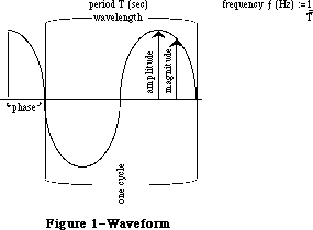 Figure 1–Waveform
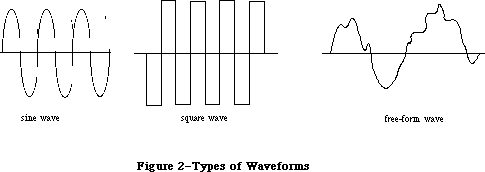 Figure 2–Types of Waveforms
Figure 3 shows analog and digital representations of a waveform. The Sound Driver represents waveforms digitally, so all waveforms must be converted from their analog representation to a digital representation. The rows of numbers at the bottom of the figure are digital representations of the waveform. The numbers in the upper row are the magnitudes relative to the horizontal zero-magnitude line. The numbers in the lower row all represent the same relative magnitudes, but have been normalized to positive numbers; you’ll use numbers like these when calling the Sound Driver.
A digital representation of a waveform is simply a sequence of wave magnitudes measured at fixed intervals. This sequence of magnitudes is stored in the Sound Driver as a sequence of bytes, each one of which specifies an instantaneous voltage to be sent to the speaker. The bytes are stored in a data structure called a waveform description. Since a sequence of bytes can only represent a group of numbers whose maximum and minimum values differ by less than 256, the magnitudes of your waveforms must be constrained to these same limits.
Figure 2–Types of Waveforms
Figure 3 shows analog and digital representations of a waveform. The Sound Driver represents waveforms digitally, so all waveforms must be converted from their analog representation to a digital representation. The rows of numbers at the bottom of the figure are digital representations of the waveform. The numbers in the upper row are the magnitudes relative to the horizontal zero-magnitude line. The numbers in the lower row all represent the same relative magnitudes, but have been normalized to positive numbers; you’ll use numbers like these when calling the Sound Driver.
A digital representation of a waveform is simply a sequence of wave magnitudes measured at fixed intervals. This sequence of magnitudes is stored in the Sound Driver as a sequence of bytes, each one of which specifies an instantaneous voltage to be sent to the speaker. The bytes are stored in a data structure called a waveform description. Since a sequence of bytes can only represent a group of numbers whose maximum and minimum values differ by less than 256, the magnitudes of your waveforms must be constrained to these same limits.
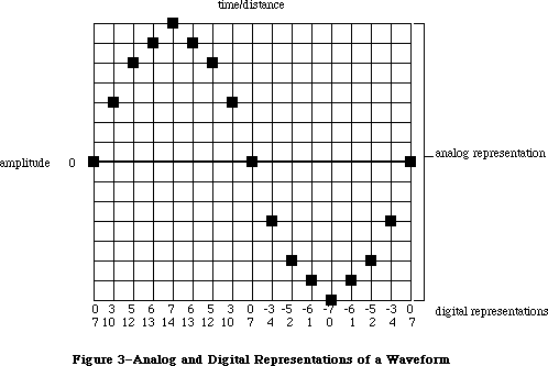 Figure 3–Analog and Digital Representations of a Waveform
_______________________________________________________________________________
»SOUND DRIVER SYNTHESIZERS
_______________________________________________________________________________
A description of the sound to be generated by a synthesizer is contained in a data structure called a synthesizer buffer. A synthesizer buffer contains the duration, pitch, phase, and waveform of the sound the synthesizer will generate. The exact structure of a synthesizer buffer differs for each type of synthesizer being used. The first word in every synthesizer buffer is an integer that identifies the synthesizer, and must be one of the following predefined constants:
CONST swMode = –1; {square-wave synthesizer}
ftMode = 1; {four-tone synthesizer}
ffMode = 0; {free-form synthesizer}
_______________________________________________________________________________
»Square-Wave Synthesizer
The square-wave synthesizer is used to make sounds such as beeps. A square-wave synthesizer buffer has the following structure:
TYPE SWSynthRec = RECORD
mode: INTEGER; {always swMode}
triplets: Tones {sounds}
END;
SWSynthPtr = ^SWSynthRec;
Tones = ARRAY[0..5000] OF Tone;
Tone = RECORD
count: INTEGER; {frequency}
amplitude: INTEGER; {amplitude, 0-255}
duration: INTEGER {duration in ticks}
END;
Each tone triplet contains the count, amplitude, and duration of a different sound. You can store as many triplets in a synthesizer buffer as there’s room for.
The count integer can range in value from 0 to 65535. The actual frequency the count corresponds to is given by the relationship:
frequency (Hz) = 783360 / count
A partial list of count values and corresponding frequencies for notes is given in the summary at the end of this chapter.
The type Tones is declared with 5001 elements to allow you to pass up to 5000 sounds (the last element must contain 0). To be space-efficient, your application shouldn’t declare a variable of type Tones; instead, you can do something like this:
VAR myPtr: Ptr;
myHandle: Handle;
mySWPtr: SWSynthPtr;
. . .
myHandle := NewHandle(buffSize); {allocate space for the buffer}
HLock(myHandle); {lock the buffer}
myPtr := myHandle^; {dereference the handle}
mySWPtr := SWSynthPtr(myPtr); {coerce type to SWSynthPtr}
mySWPtr^.mode := swMode; {identify the synthesizer}
mySWPtr^.triplets[0].count := 2; {fill the buffer with values }
. . . { describing the sound}
StartSound(myPtr,buffSize,POINTER(-1)); {produce the sound}
HUnlock(myHandle) {unlock the buffer}
where buffSize contains the number of bytes in the synthesizer buffer. This example dereferences handles instead of using pointers directly, to minimize the number of nonrelocatable objects in the heap.
Assembly-language note: The global variable CurPitch contains the current
value of the count field.
The amplitude can range from 0 to 255. The duration specifies the number of ticks that the sound will be generated.
The list of tones ends with a triplet in which all fields are set to 0. When the square-wave synthesizer is used, the sound specified by each triplet is generated once, and then the synthesizer stops.
_______________________________________________________________________________
»Four-Tone Synthesizer
The four-tone synthesizer is used to produce harmonic sounds such as music. It can simultaneously generate four different sounds, each with its own frequency, phase, and waveform.
A four-tone synthesizer buffer has the following structure:
TYPE FTSynthRec = RECORD
mode: INTEGER; {always ftMode}
sndRec: FTSndRecPtr {tones to play}
END;
FTSynthPtr = ^FTSynthRec;
The sndRec field points to a four-tone record, which describes the four tones:
TYPE FTSoundRec = RECORD
duration: INTEGER; {duration in ticks}
sound1Rate: Fixed; {tone 1 cycle rate}
sound1Phase: LONGINT; {tone 1 byte offset}
sound2Rate: Fixed; {tone 2 cycle rate}
sound2Phase: LONGINT; {tone 2 byte offset}
sound3Rate: Fixed; {tone 3 cycle rate}
sound3Phase: LONGINT; {tone 3 byte offset}
sound4Rate: Fixed; {tone 4 cycle rate}
sound4Phase: LONGINT; {tone 4 byte offset}
sound1Wave: WavePtr; {tone 1 waveform}
sound2Wave: WavePtr; {tone 2 waveform}
sound3Wave: WavePtr; {tone 3 waveform}
sound4Wave: WavePtr {tone 4 waveform}
END;
FTSndRecPtr = ^FTSoundRec:
Wave = PACKED ARRAY[0..255] OF Byte;
WavePtr = ^Wave;
Assembly-language note: The address of the four-tone record currently in use
is stored in the global variable SoundPtr.
The duration integer indicates the number of ticks that the sound will be generated. Each phase long integer indicates the byte within the waveform description at which the synthesizer should begin producing sound (the first byte is byte number 0). Each rate value determines the speed at which the synthesizer cycles through the waveform, from 0 to 255.
The four-tone synthesizer creates sound by starting at the byte in the waveform description specified by the phase, and skipping ahead the number of bytes specified by the rate field every 44.93 microseconds; when the time specified by the duration has elapsed, the synthesizer stops. The rate field determines how the waveform will be “sampled”, as shown in Figure 4. For nonperiodic waveforms, this is best illustrated by example: If the rate field is 1, each byte value in the waveform will be used, each producing sound for 44.93 microseconds. If the rate field is 0.1, each byte will be used 10 times, each therefore producing sound for a total of 449.3 microseconds. If the rate field is 5, only every fifth byte in the waveform will be sampled, each producing sound for 44.93 microseconds.
If the waveform contains one wavelength, the frequency that the rate corresponds to is given by:
frequency (Hz) = 1000000 / (44.93 / (rate/256))
You can use the Toolbox Utility routines FixMul and FixRatio to calculate this, as follows:
frequency := FixMul(rate,FixRatio(22257,256))
The maximum rate of 256 corresponds to approximately 22.3 kilohertz if the waveform contains one wavelength, and a rate of 0 produces no sound. A partial list of rate values and corresponding frequencies for notes is given in the summary at the end of this chapter.
_______________________________________________________________________________
»Free-Form Synthesizer
The free-form synthesizer is used to synthesize complex music and speech. The sound to be produced is represented as a waveform whose complexity and length are limited only by available memory.
A free-form synthesizer buffer has the following structure:
TYPE FFSynthRec = RECORD
mode: INTEGER; {always ffMode}
count: Fixed; {“sampling” factor}
waveBytes: FreeWave {waveform description}
END;
FFSynthPtr = ^FFSynthRec;
FreeWave = PACKED ARRAY[0..30000] OF Byte;
The type FreeWave is declared with 30001 elements to allow you to pass a very long waveform. To be space-efficient, your application shouldn’t declare a variable of type FreeWave; instead, you can do something like this:
VAR myPtr: Ptr;
myHandle: Handle;
myFFPtr: FFSynthPtr;
. . .
myHandle := NewHandle(buffSize); {allocate space for the buffer}
HLock(myHandle); {lock the buffer}
myPtr := myHandle^; {dereference the handle}
myFFPtr := FFSynthPtr(myPtr); {coerce type to FFSynthPtr}
myFFPtr^.mode := ffMode; {identify the synthesizer}
myFFPtr^.count := FixRatio(1,1); {fill the buffer with values }
myFFPtr^.waveBytes[0] := 0; { describing the sound}
. . .
StartSound(myPtr,buffSize,POINTER(–1)); {produce the sound}
HUnlock(myHandle) {unlock the buffer}
where buffSize contains the number of bytes in the synthesizer buffer. This example dereferences handles instead of using pointers directly, to minimize the number of nonrelocatable objects in the heap.
Figure 3–Analog and Digital Representations of a Waveform
_______________________________________________________________________________
»SOUND DRIVER SYNTHESIZERS
_______________________________________________________________________________
A description of the sound to be generated by a synthesizer is contained in a data structure called a synthesizer buffer. A synthesizer buffer contains the duration, pitch, phase, and waveform of the sound the synthesizer will generate. The exact structure of a synthesizer buffer differs for each type of synthesizer being used. The first word in every synthesizer buffer is an integer that identifies the synthesizer, and must be one of the following predefined constants:
CONST swMode = –1; {square-wave synthesizer}
ftMode = 1; {four-tone synthesizer}
ffMode = 0; {free-form synthesizer}
_______________________________________________________________________________
»Square-Wave Synthesizer
The square-wave synthesizer is used to make sounds such as beeps. A square-wave synthesizer buffer has the following structure:
TYPE SWSynthRec = RECORD
mode: INTEGER; {always swMode}
triplets: Tones {sounds}
END;
SWSynthPtr = ^SWSynthRec;
Tones = ARRAY[0..5000] OF Tone;
Tone = RECORD
count: INTEGER; {frequency}
amplitude: INTEGER; {amplitude, 0-255}
duration: INTEGER {duration in ticks}
END;
Each tone triplet contains the count, amplitude, and duration of a different sound. You can store as many triplets in a synthesizer buffer as there’s room for.
The count integer can range in value from 0 to 65535. The actual frequency the count corresponds to is given by the relationship:
frequency (Hz) = 783360 / count
A partial list of count values and corresponding frequencies for notes is given in the summary at the end of this chapter.
The type Tones is declared with 5001 elements to allow you to pass up to 5000 sounds (the last element must contain 0). To be space-efficient, your application shouldn’t declare a variable of type Tones; instead, you can do something like this:
VAR myPtr: Ptr;
myHandle: Handle;
mySWPtr: SWSynthPtr;
. . .
myHandle := NewHandle(buffSize); {allocate space for the buffer}
HLock(myHandle); {lock the buffer}
myPtr := myHandle^; {dereference the handle}
mySWPtr := SWSynthPtr(myPtr); {coerce type to SWSynthPtr}
mySWPtr^.mode := swMode; {identify the synthesizer}
mySWPtr^.triplets[0].count := 2; {fill the buffer with values }
. . . { describing the sound}
StartSound(myPtr,buffSize,POINTER(-1)); {produce the sound}
HUnlock(myHandle) {unlock the buffer}
where buffSize contains the number of bytes in the synthesizer buffer. This example dereferences handles instead of using pointers directly, to minimize the number of nonrelocatable objects in the heap.
Assembly-language note: The global variable CurPitch contains the current
value of the count field.
The amplitude can range from 0 to 255. The duration specifies the number of ticks that the sound will be generated.
The list of tones ends with a triplet in which all fields are set to 0. When the square-wave synthesizer is used, the sound specified by each triplet is generated once, and then the synthesizer stops.
_______________________________________________________________________________
»Four-Tone Synthesizer
The four-tone synthesizer is used to produce harmonic sounds such as music. It can simultaneously generate four different sounds, each with its own frequency, phase, and waveform.
A four-tone synthesizer buffer has the following structure:
TYPE FTSynthRec = RECORD
mode: INTEGER; {always ftMode}
sndRec: FTSndRecPtr {tones to play}
END;
FTSynthPtr = ^FTSynthRec;
The sndRec field points to a four-tone record, which describes the four tones:
TYPE FTSoundRec = RECORD
duration: INTEGER; {duration in ticks}
sound1Rate: Fixed; {tone 1 cycle rate}
sound1Phase: LONGINT; {tone 1 byte offset}
sound2Rate: Fixed; {tone 2 cycle rate}
sound2Phase: LONGINT; {tone 2 byte offset}
sound3Rate: Fixed; {tone 3 cycle rate}
sound3Phase: LONGINT; {tone 3 byte offset}
sound4Rate: Fixed; {tone 4 cycle rate}
sound4Phase: LONGINT; {tone 4 byte offset}
sound1Wave: WavePtr; {tone 1 waveform}
sound2Wave: WavePtr; {tone 2 waveform}
sound3Wave: WavePtr; {tone 3 waveform}
sound4Wave: WavePtr {tone 4 waveform}
END;
FTSndRecPtr = ^FTSoundRec:
Wave = PACKED ARRAY[0..255] OF Byte;
WavePtr = ^Wave;
Assembly-language note: The address of the four-tone record currently in use
is stored in the global variable SoundPtr.
The duration integer indicates the number of ticks that the sound will be generated. Each phase long integer indicates the byte within the waveform description at which the synthesizer should begin producing sound (the first byte is byte number 0). Each rate value determines the speed at which the synthesizer cycles through the waveform, from 0 to 255.
The four-tone synthesizer creates sound by starting at the byte in the waveform description specified by the phase, and skipping ahead the number of bytes specified by the rate field every 44.93 microseconds; when the time specified by the duration has elapsed, the synthesizer stops. The rate field determines how the waveform will be “sampled”, as shown in Figure 4. For nonperiodic waveforms, this is best illustrated by example: If the rate field is 1, each byte value in the waveform will be used, each producing sound for 44.93 microseconds. If the rate field is 0.1, each byte will be used 10 times, each therefore producing sound for a total of 449.3 microseconds. If the rate field is 5, only every fifth byte in the waveform will be sampled, each producing sound for 44.93 microseconds.
If the waveform contains one wavelength, the frequency that the rate corresponds to is given by:
frequency (Hz) = 1000000 / (44.93 / (rate/256))
You can use the Toolbox Utility routines FixMul and FixRatio to calculate this, as follows:
frequency := FixMul(rate,FixRatio(22257,256))
The maximum rate of 256 corresponds to approximately 22.3 kilohertz if the waveform contains one wavelength, and a rate of 0 produces no sound. A partial list of rate values and corresponding frequencies for notes is given in the summary at the end of this chapter.
_______________________________________________________________________________
»Free-Form Synthesizer
The free-form synthesizer is used to synthesize complex music and speech. The sound to be produced is represented as a waveform whose complexity and length are limited only by available memory.
A free-form synthesizer buffer has the following structure:
TYPE FFSynthRec = RECORD
mode: INTEGER; {always ffMode}
count: Fixed; {“sampling” factor}
waveBytes: FreeWave {waveform description}
END;
FFSynthPtr = ^FFSynthRec;
FreeWave = PACKED ARRAY[0..30000] OF Byte;
The type FreeWave is declared with 30001 elements to allow you to pass a very long waveform. To be space-efficient, your application shouldn’t declare a variable of type FreeWave; instead, you can do something like this:
VAR myPtr: Ptr;
myHandle: Handle;
myFFPtr: FFSynthPtr;
. . .
myHandle := NewHandle(buffSize); {allocate space for the buffer}
HLock(myHandle); {lock the buffer}
myPtr := myHandle^; {dereference the handle}
myFFPtr := FFSynthPtr(myPtr); {coerce type to FFSynthPtr}
myFFPtr^.mode := ffMode; {identify the synthesizer}
myFFPtr^.count := FixRatio(1,1); {fill the buffer with values }
myFFPtr^.waveBytes[0] := 0; { describing the sound}
. . .
StartSound(myPtr,buffSize,POINTER(–1)); {produce the sound}
HUnlock(myHandle) {unlock the buffer}
where buffSize contains the number of bytes in the synthesizer buffer. This example dereferences handles instead of using pointers directly, to minimize the number of nonrelocatable objects in the heap.
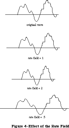 Figure 4–Effect of the Rate Field
The free-form synthesizer creates sound by starting at the first byte in the waveform and skipping ahead the number of bytes specified by count every 44.93 microseconds. The count field determines how the waveform will be “sampled”;
it’s analogous to the rate field of the four-tone synthesizer (see Figure 4 above). When the end of the waveform is reached, the synthesizer will stop.
For periodic waveforms, you can determine the frequency of the wave cycle by using the following relationship:
frequency (Hz) = 1000000 / (44.93 * (wavelength/count))
You can calculate this with Toolbox Utility routines as follows:
frequency := FixMul(count,FixRatio(22257,wavelength))
The wavelength is given in bytes. For example, the frequency of a wave with a 100-byte wavelength played at a count value of 2 would be approximately 445 Hz.
_______________________________________________________________________________
»USING THE SOUND DRIVER
_______________________________________________________________________________
The Sound Driver is opened automatically when the system starts up. Its driver name is '.Sound', and its driver reference number is –4. To close or open the Sound Driver, you can use the Device Manager Close and Open functions. Because the driver is in ROM, there’s really no reason to close it.
To use one of the three types of synthesizers to generate sound, you can do the following: Use the Memory Manager function NewHandle to allocate heap space for a synthesizer buffer; then lock the buffer, fill it with values describing the sound, and make a StartSound call to the Sound Driver. StartSound can be called either synchronously or asynchronously (with an optional completion routine). When called synchronously, control returns to your application after the sound is completed. When called asynchronously, control returns to your application immediately, and your application is free to perform other tasks while the sound is produced.
To produce continuous, unbroken sounds, it’s sometimes advantageous to preallocate space for all the synthesizer buffers you require before you make the first StartSound call. Then, while one asynchronous StartSound call is being completed, you can calculate the waveform values for the next call.
To avoid the click that may occur between StartSound calls when using the four-tone synthesizer, set the duration field to a large value and just change the value of one of the rate fields to start a new sound. To avoid the clicks that may occur during four-tone and free-form sound generation, fill the waveform description with multiples of 740 bytes.
Warning: The Sound Driver uses interrupts to produce sound. If other device
drivers are in use, they may turn off interrupts, making sound
production unreliable. For instance, if the Disk Driver is accessing
a disk during sound generation, a “crackling” sound may be produced.
To determine when the sound initiated by a StartSound call has been completed, you can poll the SoundDone function. You can cancel any current StartSound call and any pending asynchronous StartSound calls by calling StopSound. By calling GetSoundVol and SetSoundVol, you can get and set the current speaker volume level.
_______________________________________________________________________________
»SOUND DRIVER ROUTINES
_______________________________________________________________________________
PROCEDURE StartSound (synthRec: Ptr; numBytes: LONGINT;
completionRtn: ProcPtr); [Not in ROM]
Assembly-language note: StartSound is equivalent to a Device Manager Write
call with ioRefNum=–4, ioBuffer=synthRec, and
ioReqCount=numBytes.
StartSound begins producing the sound described by the synthesizer buffer pointed to by synthRec. NumBytes indicates the size of the synthesizer buffer
(in bytes), and completionRtn points to a completion routine to be executed when the sound finishes:
• If completionRtn is POINTER(–1), the sound will be produced synchronously.
• If completionRtn is NIL, the sound will be produced asynchronously, but
no completion routine will be executed.
• Otherwise, the sound will be produced asynchronously and the routine
pointed to by completionRtn will be executed when the sound finishes.
Warning: You may want the completion routine to start the next sound when one
sound finishes, but beware: Completion routines are executed at the
interrupt level and must preserve all registers other than A0, A1,
and D0-D2. They must not make any calls to the Memory Manager,
directly or indirectly, and can’t depend on handles to unlocked
blocks being valid; be sure to preallocate all the space you’ll need.
Or, instead of starting the next sound itself, the completion routine
can post an application-defined event and your application’s main
event loop can start the next sound when it gets the event.
Because the type of pointer for each type of synthesizer buffer is different and the type of the synthRec parameter is Ptr, you’ll need to do something like the following example (which applies to the free-form synthesizer):
VAR myPtr: Ptr;
myHandle: Handle;
myFFPtr: FFSynthPtr;
. . .
myHandle := NewHandle(buffSize); {allocate space for the buffer}
HLock(myHandle); {lock the buffer}
myPtr := myHandle^; {dereference the handle}
myFFPtr := FFSynthPtr(myPtr); {coerce type to FFSynthPtr}
myFFPtr^.mode := ffMode; {identify the synthesizer}
. . . {fill the buffer with values }
{ describing the sound}
StartSound(myPtr,buffSize,POINTER(-1)); {produce the sound}
HUnlock(myHandle) {unlock the buffer}
where buffSize is the number of bytes in the synthesizer buffer.
The sounds are generated as follows:
• Free-form synthesizer: The magnitudes described by each byte in the
waveform description are generated sequentially until the number of bytes
specified by the numBytes parameter have been written.
• Square-wave synthesizer: The sounds described by each sound triplet are
generated sequentially until either the end of the buffer has been reached
(indicated by a count, amplitude, and duration of 0 in the square-wave
buffer), or the number of bytes specified by the numBytes parameter have
been written.
• Four-tone synthesizer: All four sounds are generated for the length of
time specified by the duration integer in the four-tone record.
PROCEDURE StopSound; [Not in ROM]
StopSound immediately stops the current StartSound call (if any), executes the current StartSound call’s completion routine (if any), and cancels any pending asynchronous StartSound calls.
Assembly-language note: To stop sound from assembly language, you can make a
Device Manager KillIO call (and, when using the
square-wave synthesizer, set the global variable
CurPitch to 0). Although StopSound executes the
completion routine of only the current StartSound
call, KillIO executes the completion routine of every
pending asynchronous call.
FUNCTION SoundDone : BOOLEAN; [Not in ROM]
SoundDone returns TRUE if the Sound Driver isn’t currently producing sound and there are no asynchronous StartSound calls pending; otherwise it returns FALSE.
Assembly-language note: Assembly-language programmers can poll the ioResult
field of the most recent Device Manager Write call’s
parameter block to determine when the Write call
finishes.
PROCEDURE GetSoundVol (VAR level: INTEGER); [Not in ROM]
GetSoundVol returns the current speaker volume, from 0 (silent) to 7 (loudest).
Assembly-language note: Assembly-language programmers can get the speaker
volume level from the low-order three bits of the
global variable SdVolume.
PROCEDURE SetSoundVol (level: INTEGER); [Not in ROM]
SetSoundVol immediately sets the speaker volume to the specified level, from 0
(silent) to 7 (loudest); it doesn’t, however, change the volume setting that’s under user control via the Control Panel desk accessory. If your application calls SetSoundVol, it should save the current volume (using GetSoundVol) when it starts up and restore it (with SetSoundVol) upon exit; this resets the actual speaker volume to match the Control Panel setting.
Assembly-language note: To set the speaker volume level from assembly
language, call this Pascal procedure from your program.
As a side effect, it will set the low-order three bits
of the global variable SdVolume to the specified level.
Note: The Control Panel volume setting is stored in parameter RAM; if you’re
writing a similar desk accessory and want to change this setting, see
the discussion of parameter RAM in the Operating System Utilities
chapter.
_______________________________________________________________________________
»SOUND DRIVER HARDWARE
_______________________________________________________________________________
The information in this section applies to the Macintosh 128K and 512K, but not the Macintosh XL.
This section briefly describes how the Sound Driver uses the Macintosh hardware to produce sound, and how assembly-language programmers can intervene in this process to control the square-wave synthesizer. You can skip this section if it doesn’t interest you, and you’ll still be able to use the Sound Driver as described.
Note: For more information about the hardware used by the Sound Driver, see
the Macintosh Hardware chapter.
The Sound Driver and disk speed-control circuitry share a special 740-byte buffer in memory, of which the Sound Driver uses the 370 even-numbered bytes to generate sound. Every horizontal blanking interval (every 44.93 microseconds—when the beam of the display tube moves from the right edge of the screen to the left), the MC68000 automatically fetches two bytes from this buffer and sends the high-order byte to the speaker.
Note: The period of any four-tone or free-form sound generated by the Sound
Driver is a multiple of this 44.93-microsecond interval; the highest
frequency is 11128 Hz, which corresponds to twice this interval.
Every vertical blanking interval (every 16.6 milliseconds—when the beam of the display tube moves from the bottom of the screen to the top), the Sound Driver fills its half of the 740-byte buffer with the next set of values. For square-wave sound, the buffer is filled with a constant value; for more complex sound, it’s filled with many values.
From assembly language, you can cause the square-wave synthesizer to start generating sound, and then change the amplitude of the sound being generated any time you wish:
1. Make an asynchronous Device Manager Write call to the Sound Driver
specifying the count, amplitude, and duration of the sound you want.
The amplitude you specify will be placed in the 740-byte buffer, and
the Sound Driver will begin producing sound.
2. Whenever you want to change the sound being generated, make an immediate
Control call to the Sound Driver with the following parameters: ioRefNum
must be –4, csCode must be 3, and csParam must provide the new amplitude
level. The amplitude you specify will be placed in the 740-byte buffer,
and the sound will change. You can continue to change the sound until the
time specified by the duration has elapsed.
When the immediate Control call is completed, the Device Manager will execute the completion routine (if any) of the currently executing Write call. For this reason, the Write call shouldn’t have a completion routine.
Note: You can determine the amplitude placed in the 740-byte buffer from the
global variable SoundLevel.
_______________________________________________________________________________
»SUMMARY OF THE SOUND DRIVER
_______________________________________________________________________________
Constants
CONST
{ Mode values for synthesizers }
swMode = –1; {square-wave synthesizer}
ftMode = 1; {four-tone synthesizer}
ffMode = 0; {free-form synthesizer}
_______________________________________________________________________________
Data Types
TYPE
{ Free-form synthesizer }
FFSynthPtr = ^FFSynthRec;
FFSynthRec = RECORD
mode: INTEGER; {always ffMode}
count: Fixed; {“sampling” factor}
waveBytes: FreeWave {waveform description}
END;
FreeWave = PACKED ARRAY[0..30000] OF Byte;
{ Square-wave synthesizer }
SWSynthPtr = ^SWSynthRec;
SWSynthRec = RECORD
mode: INTEGER; {always swMode}
triplets: Tones {sounds}
END;
Tones = ARRAY[0..5000] OF Tone;
Tone = RECORD
count: INTEGER; {frequency}
amplitude: INTEGER; {amplitude, 0-255}
duration: INTEGER {duration in ticks}
END;
{ Four-tone synthesizer }
FTSynthPtr = ^FTSynthRec;
FTSynthRec = RECORD
mode: INTEGER; {always ftMode}
sndRec: FTSndRecPtr {tones to play}
END;
FTSndRecPtr = ^FTSoundRec:
FTSoundRec = RECORD
duration: INTEGER; {duration in ticks}
sound1Rate: Fixed; {tone 1 cycle rate}
sound1Phase: LONGINT; {tone 1 byte offset}
sound2Rate: Fixed; {tone 2 cycle rate}
sound2Phase: LONGINT; {tone 2 byte offset}
sound3Rate: Fixed; {tone 3 cycle rate}
sound3Phase: LONGINT; {tone 3 byte offset}
sound4Rate: Fixed; {tone 4 cycle rate}
sound4Phase: LONGINT; {tone 4 byte offset}
sound1Wave: WavePtr; {tone 1 waveform}
sound2Wave: WavePtr; {tone 2 waveform}
sound3Wave: WavePtr; {tone 3 waveform}
sound4Wave: WavePtr {tone 4 waveform}
END;
WavePtr = ^Wave;
Wave = PACKED ARRAY[0..255] OF Byte;
_______________________________________________________________________________
Routines
PROCEDURE StartSound (synthRec: Ptr; numBytes: LONGINT;
completionRtn: ProcPtr);
PROCEDURE StopSound;
FUNCTION SoundDone : BOOLEAN;
PROCEDURE GetSoundVol (VAR level: INTEGER);
PROCEDURE SetSoundVol (level: INTEGER);
_______________________________________________________________________________
Assembly-Language Information
Routines
Pascal name Equivalent for assembly language
StartSound Call Write with ioRefNum=–4, ioBuffer=synthRec,
ioReqCount=numBytes
StopSound Call KillIO and (for square-wave) set CurPitch to 0
SoundDone Poll ioResult field of most recent Write call’s parameter block
GetSoundVol Get low-order three bits of variable SdVolume
SetSoundVol Call this Pascal procedure from your program
Variables
SdVolume Speaker volume (byte: low-order three bits only)
SoundPtr Pointer to four-tone record
SoundLevel Amplitude in 740-byte buffer (byte)
CurPitch Value of count in square-wave synthesizer buffer (word)
Sound Driver Values for Notes
The following table contains values for the rate field of a four-tone synthesizer and the count field of a square-wave synthesizer. A just-tempered scale—in the key of C, as an example—is given in the first four columns; you can use a just-tempered scale for perfect tuning in a particular key. The last four columns give an equal-tempered scale, for applications that may use any key; this scale is appropriate for most Macintosh sound applications. Following this table is a list of the ratios used in calculating these values, and instructions on how to calculate them for a just-tempered scale in any key.
Just-Tempered Scale Equal-Tempered Scale
Rate for Count for Rate for Count for
Four-Tone Square-Wave Four-Tone Square-Wave
Note Long Fixed Word Integer Long Fixed Word Integer
3 octaves below middle C
C 612B 0.37956 5CBA 23738 604C 0.37616 5D92 23954
C# 667C 0.40033 57EB 22507 6606 0.39853 5851 22609
Db 67A6 0.40488 56EF 22255
D 6D51 0.42702 526D 21101 6C17 0.42223 535C 21340
Ebb 6E8F 0.43187 5180 20864
D# 71DF 0.44481 4F21 20257 7284 0.44733 4EAF 20143
Eb 749A 0.45547 4D46 19782
E 7976 0.47446 4A2F 18991 7953 0.47392 4A44 19012
F 818F 0.50609 458C 17804 808A 0.50211 4619 17945
F# 88A5 0.53377 41F0 16880 882F 0.53197 422A 16938
Gb 8A32 0.53983 4133 16691
G 91C1 0.56935 3DD1 15825 9048 0.56360 3E73 15987
G# 97D4 0.59308 3B58 15192 98DC 0.59711 3AF2 15090
Ab 9B79 0.60732 39F4 14836
A A1F3 0.63261 37A3 14243 A1F3 0.63261 37A3 14243
Bbb A3CA 0.63980 3703 14083
A# AA0C 0.66425 34FD 13565 AB94 0.67023 3484 13444
Bb ACBF 0.67479 3429 13353
B B631 0.71169 3174 12660 B5C8 0.71008 3191 12689
2 octaves below middle C
C C257 0.75914 2E5D 11869 C097 0.75230 2EC9 11977
C# CCF8 0.80066 2BF6 11254 CC0B 0.79704 2C29 11305
Db CF4C 0.80975 2B77 11127
D DAA2 0.85403 2936 10550 D82D 0.84444 29AE 10670
Ebb DD1D 0.86372 28C0 10432
D# E3BE 0.88962 2790 10128 E508 0.89465 2757 10071
Eb E935 0.91096 26A3 9891
E F2ED 0.94893 2517 9495 F2A6 0.94785 2522 9506
F 1031E 1.01218 22C6 8902 10114 1.00421 230C 8972
F# 1114A 1.06754 20F8 8440 1105D 1.06392 2115 8469
Gb 11465 1.07967 2099 8345
G 12382 1.13870 1EE9 7913 12090 1.12720 1F3A 7994
2 octaves below middle C
G# 12FA8 1.18616 1DAC 7596 131B8 1.19421 1D79 7545
Ab 136F1 1.21461 1CFA 7418
A 143E6 1.26523 1BD1 7121 143E6 1.26523 1BD1 7121
Bbb 14794 1.27960 1B81 7041
A# 15418 1.32849 1A7E 6782 15729 1.34047 1A42 6722
Bb 1597E 1.34958 1A14 6676
B 16C63 1.42339 18BA 6330 16B90 1.42017 18C8 6344
1 octave below middle C
C 184AE 1.51828 172F 5935 1812F 1.50462 1764 5988
C# 199EF 1.60130 15FB 5627 19816 1.59409 1614 5652
Db 19E97 1.61949 15BC 5564
D 1B543 1.70805 149B 5275 1B05A 1.68887 14D7 5335
Ebb 1BA3B 1.72746 1460 5216
D# 1C77B 1.77922 13C8 5064 1CA10 1.78931 13AC 5036
Eb 1D26A 1.82193 1351 4945
E 1E5D9 1.89784 128C 4748 1E54D 1.89571 1291 4753
F 2063D 2.02437 1163 4451 20228 2.00842 1186 4486
F# 22294 2.13507 107C 4220 220BB 2.12785 108A 4234
Gb 228C9 2.15932 104D 4173
G 24704 2.27740 F74 3956 2411F 2.25438 F9D 3997
G# 25F4F 2.37230 ED6 3798 26370 2.38843 EBC 3772
Ab 26DE3 2.42924 E7D 3709
A 287CC 2.53046 DE9 3561 287CC 2.53046 DE9 3561
Bbb 28F28 2.55920 DC1 3521
A# 2A830 2.65698 D3F 3391 2AE51 2.68092 D21 3361
Bb 2B2FC 2.69916 D0A 3338
B 2D8C6 2.84677 C5D 3165 2D721 2.84035 C64 3172
Middle C
C 3095B 3.03654 B97 2967 3025D 3.00923 BB2 2994
C# 333DE 3.20261 AFD 2813 3302C 3.18817 B0A 2826
Db 33D2E 3.23898 ADE 2782
D 36A87 3.41612 A4E 2638 360B5 3.37776 A6C 2668
Ebb 37476 3.45493 A30 2608
D# 38EF7 3.55846 9E4 2532 39420 3.57861 9D6 2518
Eb 3A4D4 3.64386 9A9 2473
E 3CBB2 3.79568 946 2374 3CA99 3.79140 949 2377
F 40C7A 4.04874 8B1 2225 40450 4.01685 8C3 2243
F# 44528 4.27014 83E 2110 44176 4.25571 845 2117
Gb 45193 4.31865 826 2086
G 48E09 4.55482 7BA 1978 4823E 4.50876 7CE 1998
G# 4BE9F 4.74461 76B 1899 4C6E1 4.77687 75E 1886
Ab 4DBC5 4.85847 73F 1855
A 50F98 5.06091 6F4 1780 50F98 5.06091 6F4 1780
Middle C
Bbb 51E4F 5.11839 6E0 1760
A# 55060 5.31396 6A0 1696 55CA2 5.36185 690 1680
Bb 565F8 5.39832 685 1669
B 5B18B 5.69353 62F 1583 5AE41 5.68068 632 1586
1 octave above middle C
C 612B7 6.07310 5CC 1484 604BB 6.01848 5D9 1497
C# 667BD 6.40523 57F 1407 66059 6.37636 585 1413
Db 67A5C 6.47797 56F 1391
D 6D50D 6.83223 527 1319 6C169 6.75551 536 1334
Ebb 6E8EB 6.90984 518 1304
D# 71DEE 7.11691 4F2 1266 7283F 7.15721 4EB 1259
Eb 749A8 7.28772 4D4 1236
E 79764 7.59137 4A3 1187 79533 7.58281 4A4 1188
F 818F3 8.09746 459 1113 808A1 8.03371 462 1122
F# 88A51 8.54030 41F 1055 882EC 8.51141 423 1059
Gb 8A326 8.63730 413 1043
G 91C12 9.10965 3DD 989 9047D 9.01753 3E7 999
G# 97D3D 9.48921 3B6 950 98DC2 9.55374 3AF 943
Ab 9B78B 9.71696 39F 927
A A1F30 10.12183 37A 890 A1F30 10.12183 37A 890
Bbb A3C9F 10.23680 370 880
A# AA0BF 10.62791 350 848 AB945 10.72371 348 840
Bb ACBEF 10.79662 343 835
B B6316 11.38705 317 791 B5C83 11.36137 319 793
2 octaves above middle C
C C256D 12.14619 2E6 742 C0976 12.03696 2ED 749
C# CCF79 12.81044 2BF 703 CC0B1 12.75270 2C3 707
Db CF4B9 12.95595 2B7 695
D DAA1B 13.66447 293 659 D82D2 13.51102 29B 667
Ebb DD1D6 13.81967 28C 652
D# E3BDC 14.23383 279 633 E507E 14.31442 275 629
Eb E9350 14.57544 26A 618
E F2EC8 15.18274 251 593 F2A65 15.16560 252 594
F 1031E7 16.19493 22C 556 101141 16.06740 231 561
F# 1114A1 17.08058 210 528 1105D8 17.02283 211 529
Gb 11464C 17.27460 20A 522
G 123824 18.21930 1EF 495 1208F9 18.03505 1F4 500
G# 12FA7B 18.97844 1DB 475 131B83 19.10747 1D8 472
Ab 136F15 19.43391 1D0 464
A 143E61 20.24367 1BD 445 143E61 20.24367 1BD 445
Bbb 14793D 20.47359 1B8 440
A# 15417F 21.25584 1A8 424 15728A 21.44742 1A4 420
Bb 1597DE 21.59323 1A1 417
B 16C62D 22.77412 18C 396 16B906 22.72275 18D 397
3 octaves above middle C
C 184ADA 24.29239 173 371 1812EB 24.07390 176 374
C# 199EF2 25.62088 160 352 198163 25.50542 161 353
Db 19E971 25.91188 15C 348
D 1B5436 27.32895 14A 330 1B05A5 27.02205 14D 333
Ebb 1BA3AC 27.63934 146 326
D# 1C77B8 28.46765 13D 317 1CA0FD 28.62886 13B 315
Eb 1D26A0 29.15088 135 309
E 1E5D91 30.36549 129 297 1E54CB 30.33122 129 297
F 2063CE 32.38986 116 278 202283 32.13481 118 280
F# 222943 34.16118 108 264 220BAF 34.04564 109 265
Gb 228C97 34.54918 105 261
G 247047 36.43858 F7 247 2411F2 36.07010 FA 250
G# 25F4F5 37.95686 ED 237 263706 38.21494 EC 236
Ab 26DE2A 38.86783 E8 232
A 287CC1 40.48732 DF 223 287CC1 40.48732 DF 223
Bbb 28F27A 40.94717 DC 220
A# 2A82FE 42.51169 D4 212 2AE513 42.89482 D2 210
Bb 2B2FBD 43.18648 D1 209
B 2D8C59 45.54823 C6 198 2D720B 45.44548 C6 198
The following table gives the ratios used in calculating the above values. It shows the relationship between the notes making up the just-tempered scale in the key of C; should you need to implement a just-tempered scale in some other key, you can do so as follows: First get the value of the root note in the proper octave in the equal-tempered scale (from the above table). Then use the following table to determine the values of the intervals for the other notes in the key by multiplying the ratio by the root note.
Chromatic Just-tempered Equal-tempered
interval Note frequency ratio frequency ratio Interval type
0 C 1.00000 1.00000 Unison
1 C# 1.05469 1.05946 Minor second as chromatic
semitone
Db 1.06667 Minor second as diatonic
semitone
2 D 1.11111 1.12246 Major second as minor tone
D 1.12500 Major second as major tone
Ebb 1.13778 Diminished third
3 D# 1.17188 1.18921 Augmented second
Eb 1.20000 Minor third
4 E 1.25000 1.25992 Major third
5 F 1.33333 1.33484 Fourth
6 F# 1.40625 1.41421 Tritone as augmented fourth
Gb 1.42222 Tritone as diminished fifth
7 G 1.50000 1.49831 Fifth
8 G# 1.56250 1.58740 Augmented fifth
Ab 1.60000 Minor sixth
9 A 1.66667 1.68179 Major sixth
Bbb 1.68560 Diminished seventh
10 A# 1.75000 1.78180 Augmented sixth
Bb 1.77778 Minor seventh
11 B 1.87500 1.88775 Major seventh
12 C 2.00000 2.00000 Octave
Further Reference:
_______________________________________________________________________________
Sound Manager
Toolbox Event Manager
Memory Manager
Device Manager
“Macintosh Family Hardware Reference”
Figure 4–Effect of the Rate Field
The free-form synthesizer creates sound by starting at the first byte in the waveform and skipping ahead the number of bytes specified by count every 44.93 microseconds. The count field determines how the waveform will be “sampled”;
it’s analogous to the rate field of the four-tone synthesizer (see Figure 4 above). When the end of the waveform is reached, the synthesizer will stop.
For periodic waveforms, you can determine the frequency of the wave cycle by using the following relationship:
frequency (Hz) = 1000000 / (44.93 * (wavelength/count))
You can calculate this with Toolbox Utility routines as follows:
frequency := FixMul(count,FixRatio(22257,wavelength))
The wavelength is given in bytes. For example, the frequency of a wave with a 100-byte wavelength played at a count value of 2 would be approximately 445 Hz.
_______________________________________________________________________________
»USING THE SOUND DRIVER
_______________________________________________________________________________
The Sound Driver is opened automatically when the system starts up. Its driver name is '.Sound', and its driver reference number is –4. To close or open the Sound Driver, you can use the Device Manager Close and Open functions. Because the driver is in ROM, there’s really no reason to close it.
To use one of the three types of synthesizers to generate sound, you can do the following: Use the Memory Manager function NewHandle to allocate heap space for a synthesizer buffer; then lock the buffer, fill it with values describing the sound, and make a StartSound call to the Sound Driver. StartSound can be called either synchronously or asynchronously (with an optional completion routine). When called synchronously, control returns to your application after the sound is completed. When called asynchronously, control returns to your application immediately, and your application is free to perform other tasks while the sound is produced.
To produce continuous, unbroken sounds, it’s sometimes advantageous to preallocate space for all the synthesizer buffers you require before you make the first StartSound call. Then, while one asynchronous StartSound call is being completed, you can calculate the waveform values for the next call.
To avoid the click that may occur between StartSound calls when using the four-tone synthesizer, set the duration field to a large value and just change the value of one of the rate fields to start a new sound. To avoid the clicks that may occur during four-tone and free-form sound generation, fill the waveform description with multiples of 740 bytes.
Warning: The Sound Driver uses interrupts to produce sound. If other device
drivers are in use, they may turn off interrupts, making sound
production unreliable. For instance, if the Disk Driver is accessing
a disk during sound generation, a “crackling” sound may be produced.
To determine when the sound initiated by a StartSound call has been completed, you can poll the SoundDone function. You can cancel any current StartSound call and any pending asynchronous StartSound calls by calling StopSound. By calling GetSoundVol and SetSoundVol, you can get and set the current speaker volume level.
_______________________________________________________________________________
»SOUND DRIVER ROUTINES
_______________________________________________________________________________
PROCEDURE StartSound (synthRec: Ptr; numBytes: LONGINT;
completionRtn: ProcPtr); [Not in ROM]
Assembly-language note: StartSound is equivalent to a Device Manager Write
call with ioRefNum=–4, ioBuffer=synthRec, and
ioReqCount=numBytes.
StartSound begins producing the sound described by the synthesizer buffer pointed to by synthRec. NumBytes indicates the size of the synthesizer buffer
(in bytes), and completionRtn points to a completion routine to be executed when the sound finishes:
• If completionRtn is POINTER(–1), the sound will be produced synchronously.
• If completionRtn is NIL, the sound will be produced asynchronously, but
no completion routine will be executed.
• Otherwise, the sound will be produced asynchronously and the routine
pointed to by completionRtn will be executed when the sound finishes.
Warning: You may want the completion routine to start the next sound when one
sound finishes, but beware: Completion routines are executed at the
interrupt level and must preserve all registers other than A0, A1,
and D0-D2. They must not make any calls to the Memory Manager,
directly or indirectly, and can’t depend on handles to unlocked
blocks being valid; be sure to preallocate all the space you’ll need.
Or, instead of starting the next sound itself, the completion routine
can post an application-defined event and your application’s main
event loop can start the next sound when it gets the event.
Because the type of pointer for each type of synthesizer buffer is different and the type of the synthRec parameter is Ptr, you’ll need to do something like the following example (which applies to the free-form synthesizer):
VAR myPtr: Ptr;
myHandle: Handle;
myFFPtr: FFSynthPtr;
. . .
myHandle := NewHandle(buffSize); {allocate space for the buffer}
HLock(myHandle); {lock the buffer}
myPtr := myHandle^; {dereference the handle}
myFFPtr := FFSynthPtr(myPtr); {coerce type to FFSynthPtr}
myFFPtr^.mode := ffMode; {identify the synthesizer}
. . . {fill the buffer with values }
{ describing the sound}
StartSound(myPtr,buffSize,POINTER(-1)); {produce the sound}
HUnlock(myHandle) {unlock the buffer}
where buffSize is the number of bytes in the synthesizer buffer.
The sounds are generated as follows:
• Free-form synthesizer: The magnitudes described by each byte in the
waveform description are generated sequentially until the number of bytes
specified by the numBytes parameter have been written.
• Square-wave synthesizer: The sounds described by each sound triplet are
generated sequentially until either the end of the buffer has been reached
(indicated by a count, amplitude, and duration of 0 in the square-wave
buffer), or the number of bytes specified by the numBytes parameter have
been written.
• Four-tone synthesizer: All four sounds are generated for the length of
time specified by the duration integer in the four-tone record.
PROCEDURE StopSound; [Not in ROM]
StopSound immediately stops the current StartSound call (if any), executes the current StartSound call’s completion routine (if any), and cancels any pending asynchronous StartSound calls.
Assembly-language note: To stop sound from assembly language, you can make a
Device Manager KillIO call (and, when using the
square-wave synthesizer, set the global variable
CurPitch to 0). Although StopSound executes the
completion routine of only the current StartSound
call, KillIO executes the completion routine of every
pending asynchronous call.
FUNCTION SoundDone : BOOLEAN; [Not in ROM]
SoundDone returns TRUE if the Sound Driver isn’t currently producing sound and there are no asynchronous StartSound calls pending; otherwise it returns FALSE.
Assembly-language note: Assembly-language programmers can poll the ioResult
field of the most recent Device Manager Write call’s
parameter block to determine when the Write call
finishes.
PROCEDURE GetSoundVol (VAR level: INTEGER); [Not in ROM]
GetSoundVol returns the current speaker volume, from 0 (silent) to 7 (loudest).
Assembly-language note: Assembly-language programmers can get the speaker
volume level from the low-order three bits of the
global variable SdVolume.
PROCEDURE SetSoundVol (level: INTEGER); [Not in ROM]
SetSoundVol immediately sets the speaker volume to the specified level, from 0
(silent) to 7 (loudest); it doesn’t, however, change the volume setting that’s under user control via the Control Panel desk accessory. If your application calls SetSoundVol, it should save the current volume (using GetSoundVol) when it starts up and restore it (with SetSoundVol) upon exit; this resets the actual speaker volume to match the Control Panel setting.
Assembly-language note: To set the speaker volume level from assembly
language, call this Pascal procedure from your program.
As a side effect, it will set the low-order three bits
of the global variable SdVolume to the specified level.
Note: The Control Panel volume setting is stored in parameter RAM; if you’re
writing a similar desk accessory and want to change this setting, see
the discussion of parameter RAM in the Operating System Utilities
chapter.
_______________________________________________________________________________
»SOUND DRIVER HARDWARE
_______________________________________________________________________________
The information in this section applies to the Macintosh 128K and 512K, but not the Macintosh XL.
This section briefly describes how the Sound Driver uses the Macintosh hardware to produce sound, and how assembly-language programmers can intervene in this process to control the square-wave synthesizer. You can skip this section if it doesn’t interest you, and you’ll still be able to use the Sound Driver as described.
Note: For more information about the hardware used by the Sound Driver, see
the Macintosh Hardware chapter.
The Sound Driver and disk speed-control circuitry share a special 740-byte buffer in memory, of which the Sound Driver uses the 370 even-numbered bytes to generate sound. Every horizontal blanking interval (every 44.93 microseconds—when the beam of the display tube moves from the right edge of the screen to the left), the MC68000 automatically fetches two bytes from this buffer and sends the high-order byte to the speaker.
Note: The period of any four-tone or free-form sound generated by the Sound
Driver is a multiple of this 44.93-microsecond interval; the highest
frequency is 11128 Hz, which corresponds to twice this interval.
Every vertical blanking interval (every 16.6 milliseconds—when the beam of the display tube moves from the bottom of the screen to the top), the Sound Driver fills its half of the 740-byte buffer with the next set of values. For square-wave sound, the buffer is filled with a constant value; for more complex sound, it’s filled with many values.
From assembly language, you can cause the square-wave synthesizer to start generating sound, and then change the amplitude of the sound being generated any time you wish:
1. Make an asynchronous Device Manager Write call to the Sound Driver
specifying the count, amplitude, and duration of the sound you want.
The amplitude you specify will be placed in the 740-byte buffer, and
the Sound Driver will begin producing sound.
2. Whenever you want to change the sound being generated, make an immediate
Control call to the Sound Driver with the following parameters: ioRefNum
must be –4, csCode must be 3, and csParam must provide the new amplitude
level. The amplitude you specify will be placed in the 740-byte buffer,
and the sound will change. You can continue to change the sound until the
time specified by the duration has elapsed.
When the immediate Control call is completed, the Device Manager will execute the completion routine (if any) of the currently executing Write call. For this reason, the Write call shouldn’t have a completion routine.
Note: You can determine the amplitude placed in the 740-byte buffer from the
global variable SoundLevel.
_______________________________________________________________________________
»SUMMARY OF THE SOUND DRIVER
_______________________________________________________________________________
Constants
CONST
{ Mode values for synthesizers }
swMode = –1; {square-wave synthesizer}
ftMode = 1; {four-tone synthesizer}
ffMode = 0; {free-form synthesizer}
_______________________________________________________________________________
Data Types
TYPE
{ Free-form synthesizer }
FFSynthPtr = ^FFSynthRec;
FFSynthRec = RECORD
mode: INTEGER; {always ffMode}
count: Fixed; {“sampling” factor}
waveBytes: FreeWave {waveform description}
END;
FreeWave = PACKED ARRAY[0..30000] OF Byte;
{ Square-wave synthesizer }
SWSynthPtr = ^SWSynthRec;
SWSynthRec = RECORD
mode: INTEGER; {always swMode}
triplets: Tones {sounds}
END;
Tones = ARRAY[0..5000] OF Tone;
Tone = RECORD
count: INTEGER; {frequency}
amplitude: INTEGER; {amplitude, 0-255}
duration: INTEGER {duration in ticks}
END;
{ Four-tone synthesizer }
FTSynthPtr = ^FTSynthRec;
FTSynthRec = RECORD
mode: INTEGER; {always ftMode}
sndRec: FTSndRecPtr {tones to play}
END;
FTSndRecPtr = ^FTSoundRec:
FTSoundRec = RECORD
duration: INTEGER; {duration in ticks}
sound1Rate: Fixed; {tone 1 cycle rate}
sound1Phase: LONGINT; {tone 1 byte offset}
sound2Rate: Fixed; {tone 2 cycle rate}
sound2Phase: LONGINT; {tone 2 byte offset}
sound3Rate: Fixed; {tone 3 cycle rate}
sound3Phase: LONGINT; {tone 3 byte offset}
sound4Rate: Fixed; {tone 4 cycle rate}
sound4Phase: LONGINT; {tone 4 byte offset}
sound1Wave: WavePtr; {tone 1 waveform}
sound2Wave: WavePtr; {tone 2 waveform}
sound3Wave: WavePtr; {tone 3 waveform}
sound4Wave: WavePtr {tone 4 waveform}
END;
WavePtr = ^Wave;
Wave = PACKED ARRAY[0..255] OF Byte;
_______________________________________________________________________________
Routines
PROCEDURE StartSound (synthRec: Ptr; numBytes: LONGINT;
completionRtn: ProcPtr);
PROCEDURE StopSound;
FUNCTION SoundDone : BOOLEAN;
PROCEDURE GetSoundVol (VAR level: INTEGER);
PROCEDURE SetSoundVol (level: INTEGER);
_______________________________________________________________________________
Assembly-Language Information
Routines
Pascal name Equivalent for assembly language
StartSound Call Write with ioRefNum=–4, ioBuffer=synthRec,
ioReqCount=numBytes
StopSound Call KillIO and (for square-wave) set CurPitch to 0
SoundDone Poll ioResult field of most recent Write call’s parameter block
GetSoundVol Get low-order three bits of variable SdVolume
SetSoundVol Call this Pascal procedure from your program
Variables
SdVolume Speaker volume (byte: low-order three bits only)
SoundPtr Pointer to four-tone record
SoundLevel Amplitude in 740-byte buffer (byte)
CurPitch Value of count in square-wave synthesizer buffer (word)
Sound Driver Values for Notes
The following table contains values for the rate field of a four-tone synthesizer and the count field of a square-wave synthesizer. A just-tempered scale—in the key of C, as an example—is given in the first four columns; you can use a just-tempered scale for perfect tuning in a particular key. The last four columns give an equal-tempered scale, for applications that may use any key; this scale is appropriate for most Macintosh sound applications. Following this table is a list of the ratios used in calculating these values, and instructions on how to calculate them for a just-tempered scale in any key.
Just-Tempered Scale Equal-Tempered Scale
Rate for Count for Rate for Count for
Four-Tone Square-Wave Four-Tone Square-Wave
Note Long Fixed Word Integer Long Fixed Word Integer
3 octaves below middle C
C 612B 0.37956 5CBA 23738 604C 0.37616 5D92 23954
C# 667C 0.40033 57EB 22507 6606 0.39853 5851 22609
Db 67A6 0.40488 56EF 22255
D 6D51 0.42702 526D 21101 6C17 0.42223 535C 21340
Ebb 6E8F 0.43187 5180 20864
D# 71DF 0.44481 4F21 20257 7284 0.44733 4EAF 20143
Eb 749A 0.45547 4D46 19782
E 7976 0.47446 4A2F 18991 7953 0.47392 4A44 19012
F 818F 0.50609 458C 17804 808A 0.50211 4619 17945
F# 88A5 0.53377 41F0 16880 882F 0.53197 422A 16938
Gb 8A32 0.53983 4133 16691
G 91C1 0.56935 3DD1 15825 9048 0.56360 3E73 15987
G# 97D4 0.59308 3B58 15192 98DC 0.59711 3AF2 15090
Ab 9B79 0.60732 39F4 14836
A A1F3 0.63261 37A3 14243 A1F3 0.63261 37A3 14243
Bbb A3CA 0.63980 3703 14083
A# AA0C 0.66425 34FD 13565 AB94 0.67023 3484 13444
Bb ACBF 0.67479 3429 13353
B B631 0.71169 3174 12660 B5C8 0.71008 3191 12689
2 octaves below middle C
C C257 0.75914 2E5D 11869 C097 0.75230 2EC9 11977
C# CCF8 0.80066 2BF6 11254 CC0B 0.79704 2C29 11305
Db CF4C 0.80975 2B77 11127
D DAA2 0.85403 2936 10550 D82D 0.84444 29AE 10670
Ebb DD1D 0.86372 28C0 10432
D# E3BE 0.88962 2790 10128 E508 0.89465 2757 10071
Eb E935 0.91096 26A3 9891
E F2ED 0.94893 2517 9495 F2A6 0.94785 2522 9506
F 1031E 1.01218 22C6 8902 10114 1.00421 230C 8972
F# 1114A 1.06754 20F8 8440 1105D 1.06392 2115 8469
Gb 11465 1.07967 2099 8345
G 12382 1.13870 1EE9 7913 12090 1.12720 1F3A 7994
2 octaves below middle C
G# 12FA8 1.18616 1DAC 7596 131B8 1.19421 1D79 7545
Ab 136F1 1.21461 1CFA 7418
A 143E6 1.26523 1BD1 7121 143E6 1.26523 1BD1 7121
Bbb 14794 1.27960 1B81 7041
A# 15418 1.32849 1A7E 6782 15729 1.34047 1A42 6722
Bb 1597E 1.34958 1A14 6676
B 16C63 1.42339 18BA 6330 16B90 1.42017 18C8 6344
1 octave below middle C
C 184AE 1.51828 172F 5935 1812F 1.50462 1764 5988
C# 199EF 1.60130 15FB 5627 19816 1.59409 1614 5652
Db 19E97 1.61949 15BC 5564
D 1B543 1.70805 149B 5275 1B05A 1.68887 14D7 5335
Ebb 1BA3B 1.72746 1460 5216
D# 1C77B 1.77922 13C8 5064 1CA10 1.78931 13AC 5036
Eb 1D26A 1.82193 1351 4945
E 1E5D9 1.89784 128C 4748 1E54D 1.89571 1291 4753
F 2063D 2.02437 1163 4451 20228 2.00842 1186 4486
F# 22294 2.13507 107C 4220 220BB 2.12785 108A 4234
Gb 228C9 2.15932 104D 4173
G 24704 2.27740 F74 3956 2411F 2.25438 F9D 3997
G# 25F4F 2.37230 ED6 3798 26370 2.38843 EBC 3772
Ab 26DE3 2.42924 E7D 3709
A 287CC 2.53046 DE9 3561 287CC 2.53046 DE9 3561
Bbb 28F28 2.55920 DC1 3521
A# 2A830 2.65698 D3F 3391 2AE51 2.68092 D21 3361
Bb 2B2FC 2.69916 D0A 3338
B 2D8C6 2.84677 C5D 3165 2D721 2.84035 C64 3172
Middle C
C 3095B 3.03654 B97 2967 3025D 3.00923 BB2 2994
C# 333DE 3.20261 AFD 2813 3302C 3.18817 B0A 2826
Db 33D2E 3.23898 ADE 2782
D 36A87 3.41612 A4E 2638 360B5 3.37776 A6C 2668
Ebb 37476 3.45493 A30 2608
D# 38EF7 3.55846 9E4 2532 39420 3.57861 9D6 2518
Eb 3A4D4 3.64386 9A9 2473
E 3CBB2 3.79568 946 2374 3CA99 3.79140 949 2377
F 40C7A 4.04874 8B1 2225 40450 4.01685 8C3 2243
F# 44528 4.27014 83E 2110 44176 4.25571 845 2117
Gb 45193 4.31865 826 2086
G 48E09 4.55482 7BA 1978 4823E 4.50876 7CE 1998
G# 4BE9F 4.74461 76B 1899 4C6E1 4.77687 75E 1886
Ab 4DBC5 4.85847 73F 1855
A 50F98 5.06091 6F4 1780 50F98 5.06091 6F4 1780
Middle C
Bbb 51E4F 5.11839 6E0 1760
A# 55060 5.31396 6A0 1696 55CA2 5.36185 690 1680
Bb 565F8 5.39832 685 1669
B 5B18B 5.69353 62F 1583 5AE41 5.68068 632 1586
1 octave above middle C
C 612B7 6.07310 5CC 1484 604BB 6.01848 5D9 1497
C# 667BD 6.40523 57F 1407 66059 6.37636 585 1413
Db 67A5C 6.47797 56F 1391
D 6D50D 6.83223 527 1319 6C169 6.75551 536 1334
Ebb 6E8EB 6.90984 518 1304
D# 71DEE 7.11691 4F2 1266 7283F 7.15721 4EB 1259
Eb 749A8 7.28772 4D4 1236
E 79764 7.59137 4A3 1187 79533 7.58281 4A4 1188
F 818F3 8.09746 459 1113 808A1 8.03371 462 1122
F# 88A51 8.54030 41F 1055 882EC 8.51141 423 1059
Gb 8A326 8.63730 413 1043
G 91C12 9.10965 3DD 989 9047D 9.01753 3E7 999
G# 97D3D 9.48921 3B6 950 98DC2 9.55374 3AF 943
Ab 9B78B 9.71696 39F 927
A A1F30 10.12183 37A 890 A1F30 10.12183 37A 890
Bbb A3C9F 10.23680 370 880
A# AA0BF 10.62791 350 848 AB945 10.72371 348 840
Bb ACBEF 10.79662 343 835
B B6316 11.38705 317 791 B5C83 11.36137 319 793
2 octaves above middle C
C C256D 12.14619 2E6 742 C0976 12.03696 2ED 749
C# CCF79 12.81044 2BF 703 CC0B1 12.75270 2C3 707
Db CF4B9 12.95595 2B7 695
D DAA1B 13.66447 293 659 D82D2 13.51102 29B 667
Ebb DD1D6 13.81967 28C 652
D# E3BDC 14.23383 279 633 E507E 14.31442 275 629
Eb E9350 14.57544 26A 618
E F2EC8 15.18274 251 593 F2A65 15.16560 252 594
F 1031E7 16.19493 22C 556 101141 16.06740 231 561
F# 1114A1 17.08058 210 528 1105D8 17.02283 211 529
Gb 11464C 17.27460 20A 522
G 123824 18.21930 1EF 495 1208F9 18.03505 1F4 500
G# 12FA7B 18.97844 1DB 475 131B83 19.10747 1D8 472
Ab 136F15 19.43391 1D0 464
A 143E61 20.24367 1BD 445 143E61 20.24367 1BD 445
Bbb 14793D 20.47359 1B8 440
A# 15417F 21.25584 1A8 424 15728A 21.44742 1A4 420
Bb 1597DE 21.59323 1A1 417
B 16C62D 22.77412 18C 396 16B906 22.72275 18D 397
3 octaves above middle C
C 184ADA 24.29239 173 371 1812EB 24.07390 176 374
C# 199EF2 25.62088 160 352 198163 25.50542 161 353
Db 19E971 25.91188 15C 348
D 1B5436 27.32895 14A 330 1B05A5 27.02205 14D 333
Ebb 1BA3AC 27.63934 146 326
D# 1C77B8 28.46765 13D 317 1CA0FD 28.62886 13B 315
Eb 1D26A0 29.15088 135 309
E 1E5D91 30.36549 129 297 1E54CB 30.33122 129 297
F 2063CE 32.38986 116 278 202283 32.13481 118 280
F# 222943 34.16118 108 264 220BAF 34.04564 109 265
Gb 228C97 34.54918 105 261
G 247047 36.43858 F7 247 2411F2 36.07010 FA 250
G# 25F4F5 37.95686 ED 237 263706 38.21494 EC 236
Ab 26DE2A 38.86783 E8 232
A 287CC1 40.48732 DF 223 287CC1 40.48732 DF 223
Bbb 28F27A 40.94717 DC 220
A# 2A82FE 42.51169 D4 212 2AE513 42.89482 D2 210
Bb 2B2FBD 43.18648 D1 209
B 2D8C59 45.54823 C6 198 2D720B 45.44548 C6 198
The following table gives the ratios used in calculating the above values. It shows the relationship between the notes making up the just-tempered scale in the key of C; should you need to implement a just-tempered scale in some other key, you can do so as follows: First get the value of the root note in the proper octave in the equal-tempered scale (from the above table). Then use the following table to determine the values of the intervals for the other notes in the key by multiplying the ratio by the root note.
Chromatic Just-tempered Equal-tempered
interval Note frequency ratio frequency ratio Interval type
0 C 1.00000 1.00000 Unison
1 C# 1.05469 1.05946 Minor second as chromatic
semitone
Db 1.06667 Minor second as diatonic
semitone
2 D 1.11111 1.12246 Major second as minor tone
D 1.12500 Major second as major tone
Ebb 1.13778 Diminished third
3 D# 1.17188 1.18921 Augmented second
Eb 1.20000 Minor third
4 E 1.25000 1.25992 Major third
5 F 1.33333 1.33484 Fourth
6 F# 1.40625 1.41421 Tritone as augmented fourth
Gb 1.42222 Tritone as diminished fifth
7 G 1.50000 1.49831 Fifth
8 G# 1.56250 1.58740 Augmented fifth
Ab 1.60000 Minor sixth
9 A 1.66667 1.68179 Major sixth
Bbb 1.68560 Diminished seventh
10 A# 1.75000 1.78180 Augmented sixth
Bb 1.77778 Minor seventh
11 B 1.87500 1.88775 Major seventh
12 C 2.00000 2.00000 Octave
Further Reference:
_______________________________________________________________________________
Sound Manager
Toolbox Event Manager
Memory Manager
Device Manager
“Macintosh Family Hardware Reference”
The Sound Manager
_______________________________________________________________________________
THE SOUND MANAGER
_______________________________________________________________________________
Sound Advice
About the Sound Manager
Using the Sound Manager
The System Beep
The Note Synthesizer
The Wave Table Synthesizer
The Sampled Sound Synthesizer
Sound Resources
Format 1 'snd ' Resource
Example Format 1 'snd '
Format 2 'snd ' Resource
Example Format 2 'snd '
The 'snth' Resource
Sound Manager Routines
SndPlay
SndNewChannel
SndAddModifier
SndDoCommand
SndDoImmediate
SndControl
SndDisposeChannel
Sound Manager Commands
User Routines
PROCEDURE CallBack
FUNCTION Modifier
The Current Sound Manager
Synthesizer Details
The Note Synthesizer
Limitations of the Note Synthesizer
The Wave Table Synthesizer
Limitations of the Wave Table Synthesizer
The Sampled Sound Synthesizer
Limitations of the Sampled Sound Synthesizer
The MIDI Synthesizer
Limitations of the MIDI Synthesizer
Sound Manager Bugs
Sound Manager Abuse
Frequently Asked Questions
Note Values and Durations
Summary of the Sound Manager
_______________________________________________________________________________
»SOUND ADVICE
_______________________________________________________________________________
This chapter describes the System 6.0.2 Sound Manager. The original chapter describing the Sound Manager is ambiguous, inaccurate, and often contradicts itself. This chapter hopefully will clear up the confusion and get developers using the Sound Manager as was originally intended. This document replaces the Sound Manager chapter originally published in Inside Macintosh.
The Sound Manager is a replacement for the older Sound Driver documented in Inside Macintosh. The abilities of the Sound Driver are currently supported by the Sound Manager and it will utilize future hardware improvements. The Sound Manager offers more flexible ways of doing things and includes new features and options, all requiring less programming effort. Many applications do not require the use of sound and therefore do not need to be concerned with the Sound Manager. Refer to the Human Interface Guideline: The Apple Desktop Interface when using sound.
A fundamental knowledge of music and sound synthesis is presumed in this document. There are utilities available from third parties that aid in the development of creating sampled sound resources. Creating wave table data or discussing the abilities of wave synthesis versus sampled sound synthesis is not covered in this document. Two good reference books are Computer Music, Synthesis, Composition, and Performance by Charles Dodge and Thomas A. Jerse, and Principles of Digital Audio by Ken Pohlman.
This document contains an overview of the Sound Manager, and a detailed description of sound resources, routines and commands. All of the known bugs and limitations are collected into one section, “The Current Sound Manager”. A “Warning” is used to point out information contained in this section that is relative to the text being read. For example, when reading about a sound command if a “Warning” is present, make sure you have read the “Current Sound Manager” section regarding that command.
_______________________________________________________________________________
»ABOUT THE SOUND MANAGER
_______________________________________________________________________________
The Sound Manager is a collection of routines that can be used to create sounds without knowledge of, or dependence on, the hardware available. By using the Sound Manager, applications are assured of upward-compatibility with future hardware and software releases. The Sound Manager will always take advantage of hardware advancements. Applications using the Sound Manager now will gain those advantages. When a command is sent to the Sound Manager, it is really a request. For example, if sound code written to play on a Macintosh II is being used on a Macintosh Plus or Macintosh SE (which have slower CPU clocks and less capable audio hardware) the Sound Manager will use synthesizers fitted best to those machine’s abilities. Conversely, future Macintoshes may have improved audio hardware, and that same code will be utilized by the Sound Manager to take full advantage of these as-yet-undetermined hardwares. All of this is transparent to the application, yet serves to make that application compatible with the full line of Macintosh computers, present and future.
A synthesizer is very similar to a device driver. A synthesizer is the code responsible for interpreting the most general sound commands and using the hardware available to produce it. A synthesizer is stored as a resource which the Sound Manager will install. Customized synthesizers are supplied for every Macintosh configuration. Only one synthesizer can be active at any time. Apple’s sound hardware is only supported when used with Apple’s synthesizers. Writing synthesizers for Apple’s hardware is not supported. Writing custom synthesizers for non-Apple hardware is beyond the scope of this document. All references to synthesizers in this document pertain to the Apple synthesizers that are supplied with the Sound Manager.
Modifiers are used to perform pre-processing of commands before they are received by a synthesizer. Modifiers can ignore, alter, remove, or add commands, or perform periodic functions. A modifier is a procedure in memory, or a resource which the Sound Manager can install. For example, if the application wanted to play a melody transposed up by an octave a modifier could be used to replace notes with notes that are an octave higher.
Instructions for a synthesizer and modifier are sent through a command queue called a sound channel. Sound channels provide a means of linking applications to the audio hardware. The application provides a sequence of commands which are processed through a number of modifiers (if any) and finally through a synthesizer that creates the sound with the hardware.
_______________________________________________________________________________
»USING THE SOUND MANAGER
_______________________________________________________________________________
The Sound Manager code that runs on the Macintosh Plus is the same that is used on the Macintosh SE. The code running on the Macintosh II is different, since it has the Apple Sound Chip installed. The Apple Sound Chip was developed to reduce the CPU’s involvement with producing sound and to extend the capabilities of the Sound Manager.
Note: The Sound Manager requires the use of the VIA1 timer T1. This conflicts
with some third party MIDI drivers. As such, it is not possible to use
both the Sound Manager and these MIDI applications.
There are two types of resources used by the Sound Manager, 'snd ' and 'snth'. A 'snd ' resource contains data and/or commands. A 'snth' resource is code used as a synthesizer or modifier to interpret the commands sent into a channel. Generally, applications only need to be concerned with 'snd ' resources. More information on the formats of 'snd ' resources and their use is given later.
The Sound Manager provides a range of methods for creating sound on the Macintosh. Most applications will only need to use a few of the Sound Manager routines. At the simplest end of the range is the use of the note synthesizer to play a simple melody or _SndPlay. _SndPlay only requires a proper 'snd ' resource. Such a resource will contain the necessary information to create a channel linked to the required synthesizer and the commands to be sent into that channel. An application can use the following code to create a sound with this method:
myChan := NIL;
sndHandle := GetNamedResource ('snd ', 'myBeep');
myErr := SndPlay (myChan, sndHandle, FALSE);
For more complete control of the sound channel, an application can open a sound channel with _SndNewChannel. The application will then send commands to that channel with _SndDoCommand or _SndDoImmediate. When the application’s sound is completed, the application closes the channel with _SndDisposeChannel.
_______________________________________________________________________________
»The System Beep
The trap _SysBeep is a call to the Sound Manager. The sound of the System Beep is selected by the user in the Control Panel using the Sound 'cdev'. Except for the “Simple Beep” _SysBeep will be performed by the Sound Manager. If this sound is selected on a Macintosh that doesn’t have the Apple Sound Chip (i.e. the Macintosh Plus and SE), the beep will be generated by the original ROM code. This has the benefit of bypassing the Sound Manager and the potential conflict of third party MIDI drivers which both use the VIA1 timer T1. Thus, this conflict over the timer can be avoided by setting the System beep to the
“Simple Beep” using the Sound 'cdev' in the Control Panel.
If an application has an active synthesizer, then _SysBeep may not generate any sound. This is because only one synthesizer can be active at any time. On a Macintosh without the Apple Sound Chip (i.e. the Plus and SE) when the “Simple Beep” is selected the beep will be heard, since it bypasses the Sound Manager. Applications should dispose of their channels as soon as they have completed making sound, allowing the _SysBeep to be heard.
Note: _SysBeep cannot be called at interrupt time since the Sound Manager will
attempt to allocate memory and load a resource.
Warning: Refer to the section “Current Sound Manager” regarding _SysBeep on
a Macintosh Plus and SE.
_______________________________________________________________________________
»The Note Synthesizer
The note synthesizer is the simplest of all the synthesizers supplied with the Sound Manager. The sound produced by this synthesizer is based upon a square wave. An application cannot play back a wave form description or recorded sound when using this synthesizer. Very little set up is required to use this synthesizer. It also has the advantage of using little CPU time. It can be used for creating simple monophonic melodies.
_______________________________________________________________________________
»The Wave Table Synthesizer
The wave table synthesizer will produce sounds based on a description of a single wave cycle. This cycle is called a wave table and is represented as an array of bytes describing the timbre (tone) of a sound. Applications may use any number of bytes to represent the wave, but 512 is the recommended length since the Sound Manager will re-sample it to this length. A wave table can be pulled in from a resource or computed by the application at run time. To install a wave table in a channel, use the waveTableCmd. Up to four wave table channels can be opened at once allowing an application to play chords, melodies with harmonies and polyphonic melodies.
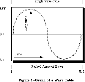 Figure 1–Graph of a Wave Table
A wave table is a sequence of wave amplitudes measured at fixed intervals. Figure 1 represents a sine wave being converted into a wave table by taking the value of the wave’s amplitude at every 1/512th interval. A wave table is represented as a PACKED ARRAY [1..512] OF BYTE. Each byte may contain the value of $00 through $FF inclusive. These bytes are considered offset values where $80 represents a zero level of amplitude, $00 is the largest negative value, and $FF is the largest positive value. The wave table synthesizer loops through the wave table for the duration of the sound.
Warning: Refer to the section “Current Sound Manager” regarding the wave table
synthesizer on the Macintosh Plus and SE.
_______________________________________________________________________________
»The Sampled Sound Synthesizer
The sampled sound synthesizer will play back digitally recorded (or computed) sounds. These sampled sounds are passed to the synthesizer in the form of a sampled sound header. This header can be played at the original sample rate, or at other rates to change its pitch. The sampled sound can be installed into a channel and then used as an instrument to play a sequence of notes. Thus a sampled sound, such as a harpsichord, can be used to play a melody. This synthesizer is typically used with pre-recorded sounds such as speech, songs or special effects. Developers concerned with saving sampled sound files need to refer to the Audio Interchange File Format available from APDA. Figure 2 shows the structure of the sampled sound header used by the sampled sound synthesizer.
Figure 1–Graph of a Wave Table
A wave table is a sequence of wave amplitudes measured at fixed intervals. Figure 1 represents a sine wave being converted into a wave table by taking the value of the wave’s amplitude at every 1/512th interval. A wave table is represented as a PACKED ARRAY [1..512] OF BYTE. Each byte may contain the value of $00 through $FF inclusive. These bytes are considered offset values where $80 represents a zero level of amplitude, $00 is the largest negative value, and $FF is the largest positive value. The wave table synthesizer loops through the wave table for the duration of the sound.
Warning: Refer to the section “Current Sound Manager” regarding the wave table
synthesizer on the Macintosh Plus and SE.
_______________________________________________________________________________
»The Sampled Sound Synthesizer
The sampled sound synthesizer will play back digitally recorded (or computed) sounds. These sampled sounds are passed to the synthesizer in the form of a sampled sound header. This header can be played at the original sample rate, or at other rates to change its pitch. The sampled sound can be installed into a channel and then used as an instrument to play a sequence of notes. Thus a sampled sound, such as a harpsichord, can be used to play a melody. This synthesizer is typically used with pre-recorded sounds such as speech, songs or special effects. Developers concerned with saving sampled sound files need to refer to the Audio Interchange File Format available from APDA. Figure 2 shows the structure of the sampled sound header used by the sampled sound synthesizer.
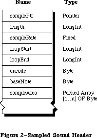 Figure 2–Sampled Sound Header
The first field of a sampled sound header is a POINTER. If the sampled sound is located immediately in memory after the baseNote, this field is NIL, otherwise it will be a pointer to the sample sound data. The length field is the number of bytes in the PACKED ARRAY [1..n] OF BYTE containing the sampled sound, n being this length.
RATE DECIMAL HEX
5kHz 5563.6363 $15BB.A2E8
7kHz 7418.1818 $1CFA.2E8B
11kHz 11127.2727 $2B77.45D1
22kHz 22254.5454 $56EE.8BA3
44kHz 44100.0000 $AC44.0000
Table 1–Sample Rates
The sampleRate is the rate at which the sample was originally recorded. These unsigned numbers are of type FIXED. The approximate sample rates are shown in Table 1.
The loop points contained within the sample header specifies the portion of the sample to be used by the Sound Manager when determining the duration of a noteCmd. These loop points specify the byte numbers in the sampled data used as the beginning and ending points to cycle through while playing the sound.
Warning: Refer to the section “Current Sound Manager” regarding the noteCmd
and looping with a sampled sound header.
The encode option is used to determine the method of encoding used in the sample. The current encode options are shown below.
stdSH = $00 {standard sound header}
extSH = $01 {extended sound header}
cmpSH = $02 {compressed sound header}
The extended sample header (extSH) is the in-memory implementation of the Audio Interchange File Format standard expected by the Sound Manager. The AIFF standard specifies up to 32 bit sample sizes, up to 128 channels per file, and much more. Refer to the AIFF documentation for more details. The compressed sample header (cmpSH) is the compressed sample counter-part of the extended sample header. Refer to the Macintosh Audio Compression and Expansion documentation for further information.
Note: Developers are free to use their own encode options with values in the
range 64-127. Apple reserves the values 0 - 63.
The baseNote is the pitch at which the original sample was taken. If a harpsichord were sampled while playing middle C, then the baseNote is middle C. The baseNote values are 1 through 127 inclusive. (Refer to Table 4.) The baseNote allows the Sound Manager to calculate the proper play back rate of the sample when an application uses the noteCmd. Applications should not modify the baseNote of a sampled sound. To use the sample at different pitches, send the noteCmd or freqCmd.
Warning: Refer to the section “Current Sound Manager” regarding limitations
with the noteCmd and freqCmd.
Each byte in the sampleArea data is similar in value to those in a wave table description. Each byte is a value of $00 through $FF inclusive $80 represents a zero level of amplitude, $00 is the largest negative value, and $FF is the largest positive value.
The Sound Manager Summary contains the description of the data format to be used with 16 bit sampled sounds. Developers wishing to write custom synthesizers for their hardware are encouraged to use this data format. This data structure is intended to complement the use of the AIFF standard.
_______________________________________________________________________________
»SOUND RESOURCES
_______________________________________________________________________________
Figure 2–Sampled Sound Header
The first field of a sampled sound header is a POINTER. If the sampled sound is located immediately in memory after the baseNote, this field is NIL, otherwise it will be a pointer to the sample sound data. The length field is the number of bytes in the PACKED ARRAY [1..n] OF BYTE containing the sampled sound, n being this length.
RATE DECIMAL HEX
5kHz 5563.6363 $15BB.A2E8
7kHz 7418.1818 $1CFA.2E8B
11kHz 11127.2727 $2B77.45D1
22kHz 22254.5454 $56EE.8BA3
44kHz 44100.0000 $AC44.0000
Table 1–Sample Rates
The sampleRate is the rate at which the sample was originally recorded. These unsigned numbers are of type FIXED. The approximate sample rates are shown in Table 1.
The loop points contained within the sample header specifies the portion of the sample to be used by the Sound Manager when determining the duration of a noteCmd. These loop points specify the byte numbers in the sampled data used as the beginning and ending points to cycle through while playing the sound.
Warning: Refer to the section “Current Sound Manager” regarding the noteCmd
and looping with a sampled sound header.
The encode option is used to determine the method of encoding used in the sample. The current encode options are shown below.
stdSH = $00 {standard sound header}
extSH = $01 {extended sound header}
cmpSH = $02 {compressed sound header}
The extended sample header (extSH) is the in-memory implementation of the Audio Interchange File Format standard expected by the Sound Manager. The AIFF standard specifies up to 32 bit sample sizes, up to 128 channels per file, and much more. Refer to the AIFF documentation for more details. The compressed sample header (cmpSH) is the compressed sample counter-part of the extended sample header. Refer to the Macintosh Audio Compression and Expansion documentation for further information.
Note: Developers are free to use their own encode options with values in the
range 64-127. Apple reserves the values 0 - 63.
The baseNote is the pitch at which the original sample was taken. If a harpsichord were sampled while playing middle C, then the baseNote is middle C. The baseNote values are 1 through 127 inclusive. (Refer to Table 4.) The baseNote allows the Sound Manager to calculate the proper play back rate of the sample when an application uses the noteCmd. Applications should not modify the baseNote of a sampled sound. To use the sample at different pitches, send the noteCmd or freqCmd.
Warning: Refer to the section “Current Sound Manager” regarding limitations
with the noteCmd and freqCmd.
Each byte in the sampleArea data is similar in value to those in a wave table description. Each byte is a value of $00 through $FF inclusive $80 represents a zero level of amplitude, $00 is the largest negative value, and $FF is the largest positive value.
The Sound Manager Summary contains the description of the data format to be used with 16 bit sampled sounds. Developers wishing to write custom synthesizers for their hardware are encouraged to use this data format. This data structure is intended to complement the use of the AIFF standard.
_______________________________________________________________________________
»SOUND RESOURCES
_______________________________________________________________________________
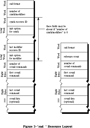 Figure 3–'snd ' Resource Layout
Sound resources are intended to be simple, portable, and dynamic solutions for incorporating sounds into applications. Creating these 'snd ' or sound resources, requires some understanding of sound synthesis to build a sampled sound header, wave table data, and sound commands. There are two types of
'snd ' resources, format 1 and format 2. Figure 3 compares the structures of both of these formats. These resources should have their purgeable bit set or the application will need to call _HPurge after using the 'snd '.
The format 1 'snd ' was developed for use with the Sound Manager. A format 1
'snd ' may be a sequence of commands describing a melody without specifying a synthesizer or modifier and without sound data. This would allow an application to use the _SndPlay routine on any channel to play that melody. A format 1 'snd ' resource may contain a sampled sound or wave table data.
The format 2 'snd ' was developed for use with HyperCard. It is intended for use with the sampled sound synthesizer only. A format 2 simply contains a sound command that points to a sampled sound header.
Warning: HyperCard (versions 1.2.1 and earlier) contain 'snd ' resources
incorrectly labeled as format 1. Refer to Macintosh Technical
Note #168.
Note: Numbers for 'snd ' resources in the range 0 through 8191 are reserved
for Apple. The 'snd ' resources numbered 1 through 4 are defined to be
the standard system beep.
A sound command contained in a 'snd ' resource with associated sound data is marked by setting the high bit of the command. This changes the param2 field of the command to be an offset value from the resource’s beginning, pointing to the location of the sound data. Refer to Figure 5 showing the structure of a sound command. To calculate this offset, use one of the following formulas below.
For a format 1 'snd ' resource, the offset is calculated as follows:
offset = 4 + (number of synth/mods * 6) + (number of cmds * 8)
For a format 2 'snd ' resource, the offset is calculated as follows:
offset = 6 + (number of cmds * 8)
The first few bytes of the resource contain 'snd ' header information and are a different size for either format. Each synthesizer or modifier specified in a format 1 'snd ' requires 6 bytes. The number of synthesizers and/or modifiers multiplied by 6 is added to this offset. The number of commands multiplied by 8 bytes, the size of a sound command, is added to the offset.
_______________________________________________________________________________
»Format 1 'snd ' Resource
Figure 3 shows the fields of a format 1 'snd ' resource. This resource may also contain the actual sound data for the wave table synthesizer or the sampled sound synthesizer. The number of synthesizer and modifiers to be used by this 'snd ' is specified in the field number of synth/modifiers. The synthesizer required to produce the sound described in the 'snd ' is specified by the field synth resource ID. If any modifiers are to be installed, their resource IDs follow the first synthesizer. Any synthesizer or modifier specified beyond this first one will be installed into the channel as a modifier.
For every synthesizer and modifier, an init option can be supplied in the field immediately following the resource ID for each synthesizer or modifier. The number of commands within the resource is specified in the field number of sound commands. Each sound command follows in the order they should be sent to the channel. If a command such as a bufferCmd is contained in this resource, it needs to specify where in the resource the sampled sound header is located. This is done by setting the high bit of the bufferCmd and supplying the offset in param2. Refer to the section “Sound Manager Commands”.
The 'snd ' resource may be only a sequence of commands describing a melody playable by any synthesizer. This allows the 'snd ' to be used on any channel. In this case the number of synth/modifiers should be 0, and there would not be a synth resource ID nor init option in the 'snd '.
»Example Format 1 'snd '
The following example resource contains the proper information to create a sound with _SndPlay and the sampled sound synthesizer.
HEX Size Meaning
{beginning of snd resource, header information}
$0001 WORD format 1 resource
$0001 WORD number of synth/modifiers to be installed
{synth ID to be used}
$0005 WORD resource ID of the first synth/modifier
$0000 0000 LONG initialization option for first synth/modifier
$0001 WORD number of sound commands to follow
{first command, 8 bytes in length}
$8051 WORD bufferCmd, high bit on to indicate sound data included
$0000 WORD bufferCmd param1
$0000 0014 LONG bufferCmd param2, offset to sound header (20 bytes)
{sampled sound header used in a soundCmd and bufferCmd}
$0000 0000 LONG pointer to data (it follows immediately}
$0000 0BB8 LONG number of samples in bytes (3000 samples)
$56EE 8BA3 LONG sampling rate of this sound (22kHz)
$0000 07D0 LONG starting of the sample’s loop point
$0000 0898 LONG ending of the sample’s loop point
$00 BYTE standard sample encoding
$3C BYTE baseNote (middle C) at which sample was taken
{Packed Array [1..3000] OF Byte, the sampled sound data}
$8080 8182 8487 9384 6F68 6D65 727B 8288
$918E 8D8F 867E 7C79 6F6D 7170 7079 7F81
$898F 8D8B...
_______________________________________________________________________________
»Format 2 'snd ' Resource
The format 2 'snd ' resource is used by the sampled sound synthesizer only and must contain a sampled sound. The _SndPlay routine supports this format by automatically opening a channel to the sample sound synthesizer and using the bufferCmd.
Figure 3 shows the fields of a format 2 'snd ' resource. The field reference count is for the application’s use and is not used by the Sound Manager. The fields number of sound commands and the sound commands are the same as described in a format 1 resource. The last field of this 'snd ' is for the sampled sound. The first command should be either a soundCmd or bufferCmd with the pointer bit set in the command to specify the location of this sampled sound header. Any other sound commands in this 'snd ' will be ignored by the Sound Manager.
»Example Format 2 'snd '
The following example resource contains the proper information to create a sound with _SndPlay and the sampled sound synthesizer.
HEX Size Meaning
{beginning of 'snd ' resource, header information}
$0002 WORD format 2 resource
$0000 WORD reference count for application’s use
$0001 WORD number of sound commands to follow
{first command, 8 bytes in length}
$8051 WORD bufferCmd, high bit on to indicate sound data included
$0000 WORD bufferCmd param1
$0000 0014 LONG bufferCmd param2, offset to sound header (20 bytes)
{sampled sound header used in a soundCmd and bufferCmd}
$0000 0000 LONG pointer to data (it follows immediately}
$0000 0BB8 LONG number of samples in bytes (3000 samples)
$56EE 8BA3 LONG sampling rate of this sound (22kHz)
$0000 07D0 LONG starting of the sample’s loop point
$0000 0898 LONG ending of the sample’s loop point
$00 BYTE standard sample encoding
$3C BYTE baseNote (middle C) at which sample was taken
{Packed Array [1..3000] OF Byte, the sampled sound data}
$8080 8182 8487 9384 6F68 6D65 727B 8288
$918E 8D8F 867E 7C79 6F6D 7170 7079 7F81
$898F 8D8B...
_______________________________________________________________________________
»The 'snth' Resource
The 'snth' resources are the routines that get linked to a sound channel used to create sound. The calls to _SndPlay, _SndNewChannel, _SndAddModifier, and
_SndControl are mapped with unique 'snth' resources based on the hardware present on each Macintosh. The Sound Manager first determines the type of Macintosh being used. Then, using the id specified in one of the four routines above, adds a constant to this id. For the Macintosh Plus and SE, a constant of $1000 is added to this id. For the Macintosh II, $800 is added to the id. If the mapped resource ID is not available, the Sound Manager will use the actual id value specified.
Note: The 'snth' resource IDs in the range 0 through 255 inclusive are
reserved for Apple within the 'snth' resource mapping range.
Resource ID Synthesizer Target Macintosh
$0001 noteSynth general for any Macintosh
$0003 waveTableSynth general for any Macintosh
$0005 sampledSynth general for any Macintosh
$0006-$00FF reserved for Apple general for any Macintosh
$0100-$0799 free for developers general for any Macintosh
$0801 noteSynth Mac with Apple Sound Chip
$0803 waveTableSynth Mac with Apple Sound Chip
$0805 sampledSynth Mac with Apple Sound Chip
$0806-$08FF reserved for Apple Mac with Apple Sound Chip
$0900-$0999 free for developers Mac with Apple Sound Chip
$1001 noteSynth Mac Plus and SE
$1003 waveTableSynth Mac Plus and SE
$1005 sampledSynth Mac Plus and SE
$1006-$10FF reserved for Apple Mac Plus and SE
$1100-$1199 free for developers Mac Plus and SE
Table 2–Synthesizer Resource IDs
For example, if an application requested the sampled sound synthesizer while running on the Macintosh Plus, it uses the resource ID of 5 when calling
_SndNewChannel. The Sound Manager will then open the 'snth' resource with the ID of $1005 since this synthesizer is specific to the Macintosh Plus. Table 2 lists the current synthesizers and the IDs used by each Macintosh.
Warning: Refer to the section “Current Sound Manager” regarding the
Macintosh II 'snth' IDs.
_______________________________________________________________________________
»SOUND MANAGER ROUTINES
_______________________________________________________________________________
Figure 3–'snd ' Resource Layout
Sound resources are intended to be simple, portable, and dynamic solutions for incorporating sounds into applications. Creating these 'snd ' or sound resources, requires some understanding of sound synthesis to build a sampled sound header, wave table data, and sound commands. There are two types of
'snd ' resources, format 1 and format 2. Figure 3 compares the structures of both of these formats. These resources should have their purgeable bit set or the application will need to call _HPurge after using the 'snd '.
The format 1 'snd ' was developed for use with the Sound Manager. A format 1
'snd ' may be a sequence of commands describing a melody without specifying a synthesizer or modifier and without sound data. This would allow an application to use the _SndPlay routine on any channel to play that melody. A format 1 'snd ' resource may contain a sampled sound or wave table data.
The format 2 'snd ' was developed for use with HyperCard. It is intended for use with the sampled sound synthesizer only. A format 2 simply contains a sound command that points to a sampled sound header.
Warning: HyperCard (versions 1.2.1 and earlier) contain 'snd ' resources
incorrectly labeled as format 1. Refer to Macintosh Technical
Note #168.
Note: Numbers for 'snd ' resources in the range 0 through 8191 are reserved
for Apple. The 'snd ' resources numbered 1 through 4 are defined to be
the standard system beep.
A sound command contained in a 'snd ' resource with associated sound data is marked by setting the high bit of the command. This changes the param2 field of the command to be an offset value from the resource’s beginning, pointing to the location of the sound data. Refer to Figure 5 showing the structure of a sound command. To calculate this offset, use one of the following formulas below.
For a format 1 'snd ' resource, the offset is calculated as follows:
offset = 4 + (number of synth/mods * 6) + (number of cmds * 8)
For a format 2 'snd ' resource, the offset is calculated as follows:
offset = 6 + (number of cmds * 8)
The first few bytes of the resource contain 'snd ' header information and are a different size for either format. Each synthesizer or modifier specified in a format 1 'snd ' requires 6 bytes. The number of synthesizers and/or modifiers multiplied by 6 is added to this offset. The number of commands multiplied by 8 bytes, the size of a sound command, is added to the offset.
_______________________________________________________________________________
»Format 1 'snd ' Resource
Figure 3 shows the fields of a format 1 'snd ' resource. This resource may also contain the actual sound data for the wave table synthesizer or the sampled sound synthesizer. The number of synthesizer and modifiers to be used by this 'snd ' is specified in the field number of synth/modifiers. The synthesizer required to produce the sound described in the 'snd ' is specified by the field synth resource ID. If any modifiers are to be installed, their resource IDs follow the first synthesizer. Any synthesizer or modifier specified beyond this first one will be installed into the channel as a modifier.
For every synthesizer and modifier, an init option can be supplied in the field immediately following the resource ID for each synthesizer or modifier. The number of commands within the resource is specified in the field number of sound commands. Each sound command follows in the order they should be sent to the channel. If a command such as a bufferCmd is contained in this resource, it needs to specify where in the resource the sampled sound header is located. This is done by setting the high bit of the bufferCmd and supplying the offset in param2. Refer to the section “Sound Manager Commands”.
The 'snd ' resource may be only a sequence of commands describing a melody playable by any synthesizer. This allows the 'snd ' to be used on any channel. In this case the number of synth/modifiers should be 0, and there would not be a synth resource ID nor init option in the 'snd '.
»Example Format 1 'snd '
The following example resource contains the proper information to create a sound with _SndPlay and the sampled sound synthesizer.
HEX Size Meaning
{beginning of snd resource, header information}
$0001 WORD format 1 resource
$0001 WORD number of synth/modifiers to be installed
{synth ID to be used}
$0005 WORD resource ID of the first synth/modifier
$0000 0000 LONG initialization option for first synth/modifier
$0001 WORD number of sound commands to follow
{first command, 8 bytes in length}
$8051 WORD bufferCmd, high bit on to indicate sound data included
$0000 WORD bufferCmd param1
$0000 0014 LONG bufferCmd param2, offset to sound header (20 bytes)
{sampled sound header used in a soundCmd and bufferCmd}
$0000 0000 LONG pointer to data (it follows immediately}
$0000 0BB8 LONG number of samples in bytes (3000 samples)
$56EE 8BA3 LONG sampling rate of this sound (22kHz)
$0000 07D0 LONG starting of the sample’s loop point
$0000 0898 LONG ending of the sample’s loop point
$00 BYTE standard sample encoding
$3C BYTE baseNote (middle C) at which sample was taken
{Packed Array [1..3000] OF Byte, the sampled sound data}
$8080 8182 8487 9384 6F68 6D65 727B 8288
$918E 8D8F 867E 7C79 6F6D 7170 7079 7F81
$898F 8D8B...
_______________________________________________________________________________
»Format 2 'snd ' Resource
The format 2 'snd ' resource is used by the sampled sound synthesizer only and must contain a sampled sound. The _SndPlay routine supports this format by automatically opening a channel to the sample sound synthesizer and using the bufferCmd.
Figure 3 shows the fields of a format 2 'snd ' resource. The field reference count is for the application’s use and is not used by the Sound Manager. The fields number of sound commands and the sound commands are the same as described in a format 1 resource. The last field of this 'snd ' is for the sampled sound. The first command should be either a soundCmd or bufferCmd with the pointer bit set in the command to specify the location of this sampled sound header. Any other sound commands in this 'snd ' will be ignored by the Sound Manager.
»Example Format 2 'snd '
The following example resource contains the proper information to create a sound with _SndPlay and the sampled sound synthesizer.
HEX Size Meaning
{beginning of 'snd ' resource, header information}
$0002 WORD format 2 resource
$0000 WORD reference count for application’s use
$0001 WORD number of sound commands to follow
{first command, 8 bytes in length}
$8051 WORD bufferCmd, high bit on to indicate sound data included
$0000 WORD bufferCmd param1
$0000 0014 LONG bufferCmd param2, offset to sound header (20 bytes)
{sampled sound header used in a soundCmd and bufferCmd}
$0000 0000 LONG pointer to data (it follows immediately}
$0000 0BB8 LONG number of samples in bytes (3000 samples)
$56EE 8BA3 LONG sampling rate of this sound (22kHz)
$0000 07D0 LONG starting of the sample’s loop point
$0000 0898 LONG ending of the sample’s loop point
$00 BYTE standard sample encoding
$3C BYTE baseNote (middle C) at which sample was taken
{Packed Array [1..3000] OF Byte, the sampled sound data}
$8080 8182 8487 9384 6F68 6D65 727B 8288
$918E 8D8F 867E 7C79 6F6D 7170 7079 7F81
$898F 8D8B...
_______________________________________________________________________________
»The 'snth' Resource
The 'snth' resources are the routines that get linked to a sound channel used to create sound. The calls to _SndPlay, _SndNewChannel, _SndAddModifier, and
_SndControl are mapped with unique 'snth' resources based on the hardware present on each Macintosh. The Sound Manager first determines the type of Macintosh being used. Then, using the id specified in one of the four routines above, adds a constant to this id. For the Macintosh Plus and SE, a constant of $1000 is added to this id. For the Macintosh II, $800 is added to the id. If the mapped resource ID is not available, the Sound Manager will use the actual id value specified.
Note: The 'snth' resource IDs in the range 0 through 255 inclusive are
reserved for Apple within the 'snth' resource mapping range.
Resource ID Synthesizer Target Macintosh
$0001 noteSynth general for any Macintosh
$0003 waveTableSynth general for any Macintosh
$0005 sampledSynth general for any Macintosh
$0006-$00FF reserved for Apple general for any Macintosh
$0100-$0799 free for developers general for any Macintosh
$0801 noteSynth Mac with Apple Sound Chip
$0803 waveTableSynth Mac with Apple Sound Chip
$0805 sampledSynth Mac with Apple Sound Chip
$0806-$08FF reserved for Apple Mac with Apple Sound Chip
$0900-$0999 free for developers Mac with Apple Sound Chip
$1001 noteSynth Mac Plus and SE
$1003 waveTableSynth Mac Plus and SE
$1005 sampledSynth Mac Plus and SE
$1006-$10FF reserved for Apple Mac Plus and SE
$1100-$1199 free for developers Mac Plus and SE
Table 2–Synthesizer Resource IDs
For example, if an application requested the sampled sound synthesizer while running on the Macintosh Plus, it uses the resource ID of 5 when calling
_SndNewChannel. The Sound Manager will then open the 'snth' resource with the ID of $1005 since this synthesizer is specific to the Macintosh Plus. Table 2 lists the current synthesizers and the IDs used by each Macintosh.
Warning: Refer to the section “Current Sound Manager” regarding the
Macintosh II 'snth' IDs.
_______________________________________________________________________________
»SOUND MANAGER ROUTINES
_______________________________________________________________________________
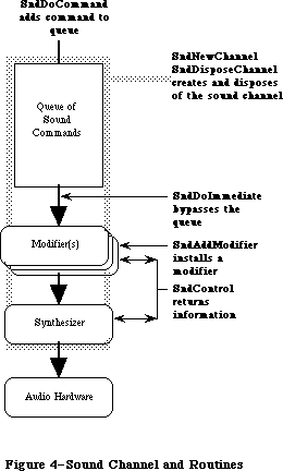 Figure 4–Sound Channel and Routines
_______________________________________________________________________________
»SndPlay
FUNCTION SndPlay (chan: SndChannelPtr; sndHdl: Handle;
async: BOOLEAN) : OSErr;
The function _SndPlay is a higher level sound routine and is generally used separately from the other Sound Manager calls. _SndPlay will attempt to play the sound specified in the 'snd ' resource located at sndHdl. This is the only Sound Manager routine that accepts a 'snd ' resource as one of its parameters. If a format 1 'snd ' specifies a synthesizer and any modifiers, those 'snth' resource(s) will be loaded in memory and linked to the channel. All commands contained in the 'snd ' will be sent to the channel. If the application passes NIL as the channel pointer, _SndPlay will create a channel in the application’s heap. The Sound Manager will release this memory after the sound has completed. The async parameter is ignored if NIL is passed as the channel pointer.
If the application does supply a channel pointer in chan, the sound can be produced asynchronously. When sound is played asynchronously, a completion routine can be called when the last command has finished processing. This procedure is the userRoutine supplied with _SndNewChannel. _SndPlay will call
_HGetState on the 'snd ' resource before _HMoveHi and _HLock, and once the sound has completed, will restore the state of the 'snd ' resource’s handle with _HSetState.
If the format 1 'snd ' resource does not specify which synthesizer is to be used, _SndPlay will default to the note synthesizer. _SndPlay will also support a format 2 'snd ' resource using the sampled sound synthesizer and a bufferCmd. Note that a format 1 'snd ' must use have a bufferCmd in order to be used with _SndPlay and the sampled sound synthesizer.
Warning: Do not use _SndPlay with a 'snd ' that specifies a synthesizer ID if
the channel has already been linked to a synthesizer.
_______________________________________________________________________________
»SndNewChannel
FUNCTION SndNewChannel (VAR chan: SndChannelPtr; synth: INTEGER;
init: LONGINT; userRoutine: ProcPtr) : OSErr;
When NIL is passed as the chan parameter, _SndNewChannel will allocate a sound channel record in the application’s heap and return its POINTER. Applications concerned with memory management can allocate their own channel memory and pass this POINTER in the chan parameter. Typically this should not present a problem since a channel should only be in use temporarily. Each channel will hold 128 commands as a default size. The length of a channel can be expanded by the application creating its own channel in memory.
The synth parameter is used to specify which synthesizer is to be used. The application specifies a synthesizer by its resource ID, and this 'snth' resource will be loaded and linked to the channel. The state of the 'snth' handle will be saved with _HGetState. To create a channel without linking it with a synthesizer, pass 0 as the synth. This is useful when using _SndPlay with a 'snd ' that specifies a synthesizer ID.
The application may specify an init option that should be sent to the synthesizer when opening the channel. For example, to open the third wave table channel use initChan2 as the init. Only the wave table synthesizer and sampled sound synthesizer currently use the init options. To determine if a particular option is available by the synthesizer, use the availableCmd.
initChanLeft = $02; {left channel - sampleSynth only}
initChanRight = $03; {right channel- sampleSynth only}
initChan0 = $04; {channel 1 - wave table only}
initChan1 = $05; {channel 2 - wave table only}
initChan2 = $06; {channel 3 - wave table only}
initChan3 = $07; {channel 4 - wave table only}
initSRate22k = $20; {22k sampling rate - sampleSynth only}
initSRate44k = $30; {44k sampling rate - sampleSynth only}
initMono = $80; {monophonic channel - sampleSynth only}
initStereo = $C0; {stereo channel - sampleSynth only}
Warning: Refer to the section “Current Sound Manager” regarding init options
and the sampled sound synthesizer.
If an application is to produce sounds asynchronously or needs to be alerted when a command has completed, it uses a CallBack procedure. This routine will be called once the callBackCmd has been received by the synthesizer. If you pass NIL as the userRoutine, then any callBack command will be ignored.
_______________________________________________________________________________
»SndAddModifier
FUNCTION SndAddModifier (chan: SndChannelPtr; modifier: ProcPtr;
id: INTEGER; init: LONGINT) : OSErr;
This routine is used to install a modifier into an open channel specified in chan. The modifier will be installed in front of the synthesizer or any existing modifiers in the channel. If the modifier is saved as a 'snth' resource, pass NIL for the ProcPtr and specify its resource ID in the parameter id. This will cause the Sound Manager to load the 'snth' resource, lock it in memory, and link it to the channel specified. The state of the 'snth' resource handle will be saved with _HGetState. Refer to the section “User Routines” for more information regarding writing a modifier.
Warning: Refer to the section “Current Sound Manager” regarding modifier
resources.
_______________________________________________________________________________
»SndDoCommand
FUNCTION SndDoCommand (chan: SndChannelPtr; cmd: SndCommand;
noWait: BOOLEAN) : OSErr;
This routine will send the sound command specified in cmd to the existing channel’s command queue. If the parameter noWait is set to FALSE and the queue is full, the Sound Manager will wait until there is space to add the command. If noWait is set to TRUE and the channel is full, the Sound Manager will not send the command and returns the error “queueFull”.
_______________________________________________________________________________
»SndDoImmediate
FUNCTION SndDoImmediate (chan: SndChannelPtr; cmd: SndCommand): OSErr;
This routine will bypass the command queue of the existing channel and send the specified command directly to the synthesizer, or the first modifier. This routine will also override any waitCmd, pauseCmd or syncCmd that may have been received by the synthesizer or modifiers.
_______________________________________________________________________________
»SndControl
FUNCTION SndControl (id: INTEGER; VAR cmd: SndCommand) : OSErr;
This routine is used to send control commands directly to a synthesizer or modifier specified by its resource ID. This can be called even if no channel has been created for the synthesizer. This control call is used with the availableCmd or versionCmd to request information regarding a synthesizer.
The result of this call is returned in cmd.
_______________________________________________________________________________
»SndDisposeChannel
FUNCTION SndDisposeChannel (chan: SndChannelPtr; quietNow: BOOLEAN) : OSErr;
This routine will dispose of the channel specified in chan and release all memory created by the Sound Manager. If an application created its own channel record in memory or installed a sound as an instrument, the Sound Manager will not dispose of that memory. The Sound Manager will restore the original state of 'snth' resource handles with a call to _HSetState.
_SndDisposeChannel can either immediately dispose of a channel or wait until the queued commands are processed. If quietNow is set to TRUE, a flushCmd and then a quietCmd is sent to the channel. This will remove all commands, stop any sound in progress and close the channel. If quietNow is set to FALSE, then the Sound Manager will issue a quietCmd only and wait until the quietCmd is received by the synthesizer before disposing of the channel. In this situation _SndDisposeChannel will be synchronous.
_______________________________________________________________________________
»SOUND MANAGER COMMANDS
_______________________________________________________________________________
Command Descriptions
Sound commands are placed into a channel one after the other. At the end of the channel is the synthesizer which interprets the command and plays the sound with the hardware. All synthesizers are designed to accept the most general set of sound commands. Some commands are specific to only a particular synthesizer. There are some commands and options that may not be currently implemented by a synthesizer. Refer to section “The Current Sound Manager” for more details.
Figure 4–Sound Channel and Routines
_______________________________________________________________________________
»SndPlay
FUNCTION SndPlay (chan: SndChannelPtr; sndHdl: Handle;
async: BOOLEAN) : OSErr;
The function _SndPlay is a higher level sound routine and is generally used separately from the other Sound Manager calls. _SndPlay will attempt to play the sound specified in the 'snd ' resource located at sndHdl. This is the only Sound Manager routine that accepts a 'snd ' resource as one of its parameters. If a format 1 'snd ' specifies a synthesizer and any modifiers, those 'snth' resource(s) will be loaded in memory and linked to the channel. All commands contained in the 'snd ' will be sent to the channel. If the application passes NIL as the channel pointer, _SndPlay will create a channel in the application’s heap. The Sound Manager will release this memory after the sound has completed. The async parameter is ignored if NIL is passed as the channel pointer.
If the application does supply a channel pointer in chan, the sound can be produced asynchronously. When sound is played asynchronously, a completion routine can be called when the last command has finished processing. This procedure is the userRoutine supplied with _SndNewChannel. _SndPlay will call
_HGetState on the 'snd ' resource before _HMoveHi and _HLock, and once the sound has completed, will restore the state of the 'snd ' resource’s handle with _HSetState.
If the format 1 'snd ' resource does not specify which synthesizer is to be used, _SndPlay will default to the note synthesizer. _SndPlay will also support a format 2 'snd ' resource using the sampled sound synthesizer and a bufferCmd. Note that a format 1 'snd ' must use have a bufferCmd in order to be used with _SndPlay and the sampled sound synthesizer.
Warning: Do not use _SndPlay with a 'snd ' that specifies a synthesizer ID if
the channel has already been linked to a synthesizer.
_______________________________________________________________________________
»SndNewChannel
FUNCTION SndNewChannel (VAR chan: SndChannelPtr; synth: INTEGER;
init: LONGINT; userRoutine: ProcPtr) : OSErr;
When NIL is passed as the chan parameter, _SndNewChannel will allocate a sound channel record in the application’s heap and return its POINTER. Applications concerned with memory management can allocate their own channel memory and pass this POINTER in the chan parameter. Typically this should not present a problem since a channel should only be in use temporarily. Each channel will hold 128 commands as a default size. The length of a channel can be expanded by the application creating its own channel in memory.
The synth parameter is used to specify which synthesizer is to be used. The application specifies a synthesizer by its resource ID, and this 'snth' resource will be loaded and linked to the channel. The state of the 'snth' handle will be saved with _HGetState. To create a channel without linking it with a synthesizer, pass 0 as the synth. This is useful when using _SndPlay with a 'snd ' that specifies a synthesizer ID.
The application may specify an init option that should be sent to the synthesizer when opening the channel. For example, to open the third wave table channel use initChan2 as the init. Only the wave table synthesizer and sampled sound synthesizer currently use the init options. To determine if a particular option is available by the synthesizer, use the availableCmd.
initChanLeft = $02; {left channel - sampleSynth only}
initChanRight = $03; {right channel- sampleSynth only}
initChan0 = $04; {channel 1 - wave table only}
initChan1 = $05; {channel 2 - wave table only}
initChan2 = $06; {channel 3 - wave table only}
initChan3 = $07; {channel 4 - wave table only}
initSRate22k = $20; {22k sampling rate - sampleSynth only}
initSRate44k = $30; {44k sampling rate - sampleSynth only}
initMono = $80; {monophonic channel - sampleSynth only}
initStereo = $C0; {stereo channel - sampleSynth only}
Warning: Refer to the section “Current Sound Manager” regarding init options
and the sampled sound synthesizer.
If an application is to produce sounds asynchronously or needs to be alerted when a command has completed, it uses a CallBack procedure. This routine will be called once the callBackCmd has been received by the synthesizer. If you pass NIL as the userRoutine, then any callBack command will be ignored.
_______________________________________________________________________________
»SndAddModifier
FUNCTION SndAddModifier (chan: SndChannelPtr; modifier: ProcPtr;
id: INTEGER; init: LONGINT) : OSErr;
This routine is used to install a modifier into an open channel specified in chan. The modifier will be installed in front of the synthesizer or any existing modifiers in the channel. If the modifier is saved as a 'snth' resource, pass NIL for the ProcPtr and specify its resource ID in the parameter id. This will cause the Sound Manager to load the 'snth' resource, lock it in memory, and link it to the channel specified. The state of the 'snth' resource handle will be saved with _HGetState. Refer to the section “User Routines” for more information regarding writing a modifier.
Warning: Refer to the section “Current Sound Manager” regarding modifier
resources.
_______________________________________________________________________________
»SndDoCommand
FUNCTION SndDoCommand (chan: SndChannelPtr; cmd: SndCommand;
noWait: BOOLEAN) : OSErr;
This routine will send the sound command specified in cmd to the existing channel’s command queue. If the parameter noWait is set to FALSE and the queue is full, the Sound Manager will wait until there is space to add the command. If noWait is set to TRUE and the channel is full, the Sound Manager will not send the command and returns the error “queueFull”.
_______________________________________________________________________________
»SndDoImmediate
FUNCTION SndDoImmediate (chan: SndChannelPtr; cmd: SndCommand): OSErr;
This routine will bypass the command queue of the existing channel and send the specified command directly to the synthesizer, or the first modifier. This routine will also override any waitCmd, pauseCmd or syncCmd that may have been received by the synthesizer or modifiers.
_______________________________________________________________________________
»SndControl
FUNCTION SndControl (id: INTEGER; VAR cmd: SndCommand) : OSErr;
This routine is used to send control commands directly to a synthesizer or modifier specified by its resource ID. This can be called even if no channel has been created for the synthesizer. This control call is used with the availableCmd or versionCmd to request information regarding a synthesizer.
The result of this call is returned in cmd.
_______________________________________________________________________________
»SndDisposeChannel
FUNCTION SndDisposeChannel (chan: SndChannelPtr; quietNow: BOOLEAN) : OSErr;
This routine will dispose of the channel specified in chan and release all memory created by the Sound Manager. If an application created its own channel record in memory or installed a sound as an instrument, the Sound Manager will not dispose of that memory. The Sound Manager will restore the original state of 'snth' resource handles with a call to _HSetState.
_SndDisposeChannel can either immediately dispose of a channel or wait until the queued commands are processed. If quietNow is set to TRUE, a flushCmd and then a quietCmd is sent to the channel. This will remove all commands, stop any sound in progress and close the channel. If quietNow is set to FALSE, then the Sound Manager will issue a quietCmd only and wait until the quietCmd is received by the synthesizer before disposing of the channel. In this situation _SndDisposeChannel will be synchronous.
_______________________________________________________________________________
»SOUND MANAGER COMMANDS
_______________________________________________________________________________
Command Descriptions
Sound commands are placed into a channel one after the other. At the end of the channel is the synthesizer which interprets the command and plays the sound with the hardware. All synthesizers are designed to accept the most general set of sound commands. Some commands are specific to only a particular synthesizer. There are some commands and options that may not be currently implemented by a synthesizer. Refer to section “The Current Sound Manager” for more details.
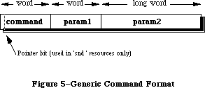 Figure 5–Generic Command Format
Figure 5 shows the structure of a generic sound command. Commands are always eight bytes in length. The first two bytes are the command number, and the next six make up the command’s options. The format of these last six bytes will depend on the command being used.
The pointer bit is only used by 'snd ' resources that contain commands and associated sound data (i.e. sampled sound or wave table data). If the high bit of the command is set, then param2 is an offset specifying where the associated data is located. This offset is the number of bytes starting from the beginning of the resource to the associated sound data. The section “Sound Resources” shows how this offset is calculated.
cmd=nullCmd param1=0 param2=0
This command is sent by modifiers. It is simply absorbed by the Sound Manager and no action is performed. Modifiers use a nullCmd to replace commands in a channel to prevent them from being sent to a synthesizer.
cmd=initCmd param1=0 param2=init
This command is only sent by the Sound Manager. It will send an initCmd to the synthesizer when an application uses the routines _SndPlay, _SndNewChannel or
_SndAddModifier. This causes a synthesizer or modifier to allocate its private memory storage and to use the init option.
cmd=freeCmd param1=0 param2=0
This command is only sent by the Sound Manager. It is exactly opposite of the initCmd. When an application calls _SndDisposeChannel, the Sound Manager will send the freeCmd to the synthesizer. This causes the synthesizer to dispose of all the private memory it had allocated.
cmd=quietCmd param1=0 param2=0
This command is sent by an application using _SndDoImmediate. It will cause the synthesizer to stop any sound in progress. It is also sent by the Sound Manager with the _SndDisposeChannel routine.
cmd=flushCmd param1=0 param2=0
This command is sent by an application using _SndDoImmediate. It will cause all commands in the channel be be removed. It is also sent by the Sound Manager from _SndDisposeChannel when quietNow is TRUE.
cmd=waitCmd param1=duration param2=0
This command is sent by an application or a modifier. It will suspend all processing in the channel for the number of half-milliseconds specified in duration. A one second wait would be a duration of 2000.
cmd=pauseCmd param1=0 param2=0
This command is sent by an application or a modifier to cause the channel to suspend processing until a tickleCmd or resumeCmd is received.
cmd=resumeCmd param1=0 param2=0
This command is sent by an application or a modifier to cause a channel to resume processing of commands. This is the opposite of the pauseCmd.
cmd=callBackCmd param1=user-defined param2=user-defined
This command is sent by an application. The callBackCmd causes the Sound Manager to call the userRoutine specified in _SndNewChannel. The two parameters of this command can be used by the application for any purpose. This allows an application to have a general userRoutine for any channel. By using param1 and param2 with unique values, the CallBack procedure can test for specific actions to take. Refer to the section “User Routines”.
This command is used as a marker for an application to determine at what point the channel has reached in processing its queue. It is mostly used to determine when to dispose of a channel, since the callBackCmd is generally the last command sent. It can also be used to allow an application to synchronize sounds with other actions.
cmd=syncCmd param1=count param2=identifier
This command is sent by an application. Every syncCmd is held in the channel, suspending any further processing until its count equals 0. The Sound Manager will first decrement the count and then wait for another syncCmd having the same identifier to be received on another channel.
To synchronize four wave table channels, send the syncCmd to each channel with count = 4 giving each command the same identifier. If a channel should wait for two more syncCmds, then its count would be 3. If a channel is to wait for one more syncCmd, its count would be sent as 2.
Warning: Refer to the section “Current Sound Manager” regarding the count
parameter of a syncCmd.
cmd=emptyCmd param1=0 param2=0
This command is only sent by the Sound Manager. Synthesizers expect to receive additional commands after a resumeCmd. If no other commands are to be sent, the Sound Manager will send an emptyCmd.
cmd=tickleCmd param1=0 param2=0
This command is only sent by the Sound Manager to a modifier. This will cause modifiers to perform their requested periodic actions. If the tickleCmd had been requested by a howOftenCmd, then a tickleCmd will be sent periodically according to the period specified in the howOftenCmd. If the tickleCmd had been requested by an wakeUpCmd, then this command will be sent only once according to the period specified in the wakeUpCmd. A tickleCmd command will also resume a channel suspended by a pauseCmd.
cmd=requestNextCmd param1=count param2=0
This command is only sent by the Sound Manager in response to a modifier returning TRUE. Refer to the section “User Routine” discussing modifiers. Count is the number of consecutive times that the modifier has requested another command.
cmd=howOftenCmd param1=period param2=pointer
This command is sent by a modifier and will instruct the Sound Manager to periodically send a tickleCmd. Param1 contains the period (in half-milliseconds) that a tickleCmd should be sent. Param2 contains a POINTER to the modifier stub.
cmd=wakeUpCmd param1=period param2=pointer
This command is sent by a modifier and will instruct the Sound Manager to send a single tickleCmd after the period specified (in half-milliseconds). Param2 contains a POINTER to the modifier stub.
Note: The howOftenCmd and the wakeUpCmd are mutually exclusive. Sending one
will cancel the other.
cmd=availableCmd param1=result param2=init
This command is sent by an application to determine if certain characteristics specified in the init parameter are available from the synthesizer. This command can only be used with the _SndControl routine. These init options are documented under the _SndNewChannel routine and are passed in param2 of the availableCmd.
myCmd.cmd := availableCmd;
myCmd.param1 := 0;
myCmd.param2 := initStereo; {we’ll test for a stereo channel}
myErr := SndControl (sampledSynth, myCmd);
IF (myCmd.param1 <> 0) THEN stereoAvailable := TRUE;
The result is returned in param1. A result of 1 is returned if the synthesizer has the requested characteristics. If it does not, the result is 0.
Warning: Refer to section “Current Sound Manager” regarding limitations with
the availableCmd.
cmd=versionCmd param1=0 param2=version
This command is sent by applications and the Sound Manager to determine which version of the synthesizer is available. The versionCmd can only be sent with the _SndControl routine. The version is returned in param2. Version 1.2 of a synthesizer would be returned as $0001 0002.
cmd=noteCmd param1=duration param2=amplitude + frequency
This command is sent by applications and modifiers to specify a note for either the note synthesizer, or with an instrument installed into the channel. The duration parameter is in half-milliseconds. A duration of 2000 would be a duration of one second. The maximum duration is a duration of 32767 or about 16 seconds. The structure of a noteCmd is given in Figure 6.
Figure 5–Generic Command Format
Figure 5 shows the structure of a generic sound command. Commands are always eight bytes in length. The first two bytes are the command number, and the next six make up the command’s options. The format of these last six bytes will depend on the command being used.
The pointer bit is only used by 'snd ' resources that contain commands and associated sound data (i.e. sampled sound or wave table data). If the high bit of the command is set, then param2 is an offset specifying where the associated data is located. This offset is the number of bytes starting from the beginning of the resource to the associated sound data. The section “Sound Resources” shows how this offset is calculated.
cmd=nullCmd param1=0 param2=0
This command is sent by modifiers. It is simply absorbed by the Sound Manager and no action is performed. Modifiers use a nullCmd to replace commands in a channel to prevent them from being sent to a synthesizer.
cmd=initCmd param1=0 param2=init
This command is only sent by the Sound Manager. It will send an initCmd to the synthesizer when an application uses the routines _SndPlay, _SndNewChannel or
_SndAddModifier. This causes a synthesizer or modifier to allocate its private memory storage and to use the init option.
cmd=freeCmd param1=0 param2=0
This command is only sent by the Sound Manager. It is exactly opposite of the initCmd. When an application calls _SndDisposeChannel, the Sound Manager will send the freeCmd to the synthesizer. This causes the synthesizer to dispose of all the private memory it had allocated.
cmd=quietCmd param1=0 param2=0
This command is sent by an application using _SndDoImmediate. It will cause the synthesizer to stop any sound in progress. It is also sent by the Sound Manager with the _SndDisposeChannel routine.
cmd=flushCmd param1=0 param2=0
This command is sent by an application using _SndDoImmediate. It will cause all commands in the channel be be removed. It is also sent by the Sound Manager from _SndDisposeChannel when quietNow is TRUE.
cmd=waitCmd param1=duration param2=0
This command is sent by an application or a modifier. It will suspend all processing in the channel for the number of half-milliseconds specified in duration. A one second wait would be a duration of 2000.
cmd=pauseCmd param1=0 param2=0
This command is sent by an application or a modifier to cause the channel to suspend processing until a tickleCmd or resumeCmd is received.
cmd=resumeCmd param1=0 param2=0
This command is sent by an application or a modifier to cause a channel to resume processing of commands. This is the opposite of the pauseCmd.
cmd=callBackCmd param1=user-defined param2=user-defined
This command is sent by an application. The callBackCmd causes the Sound Manager to call the userRoutine specified in _SndNewChannel. The two parameters of this command can be used by the application for any purpose. This allows an application to have a general userRoutine for any channel. By using param1 and param2 with unique values, the CallBack procedure can test for specific actions to take. Refer to the section “User Routines”.
This command is used as a marker for an application to determine at what point the channel has reached in processing its queue. It is mostly used to determine when to dispose of a channel, since the callBackCmd is generally the last command sent. It can also be used to allow an application to synchronize sounds with other actions.
cmd=syncCmd param1=count param2=identifier
This command is sent by an application. Every syncCmd is held in the channel, suspending any further processing until its count equals 0. The Sound Manager will first decrement the count and then wait for another syncCmd having the same identifier to be received on another channel.
To synchronize four wave table channels, send the syncCmd to each channel with count = 4 giving each command the same identifier. If a channel should wait for two more syncCmds, then its count would be 3. If a channel is to wait for one more syncCmd, its count would be sent as 2.
Warning: Refer to the section “Current Sound Manager” regarding the count
parameter of a syncCmd.
cmd=emptyCmd param1=0 param2=0
This command is only sent by the Sound Manager. Synthesizers expect to receive additional commands after a resumeCmd. If no other commands are to be sent, the Sound Manager will send an emptyCmd.
cmd=tickleCmd param1=0 param2=0
This command is only sent by the Sound Manager to a modifier. This will cause modifiers to perform their requested periodic actions. If the tickleCmd had been requested by a howOftenCmd, then a tickleCmd will be sent periodically according to the period specified in the howOftenCmd. If the tickleCmd had been requested by an wakeUpCmd, then this command will be sent only once according to the period specified in the wakeUpCmd. A tickleCmd command will also resume a channel suspended by a pauseCmd.
cmd=requestNextCmd param1=count param2=0
This command is only sent by the Sound Manager in response to a modifier returning TRUE. Refer to the section “User Routine” discussing modifiers. Count is the number of consecutive times that the modifier has requested another command.
cmd=howOftenCmd param1=period param2=pointer
This command is sent by a modifier and will instruct the Sound Manager to periodically send a tickleCmd. Param1 contains the period (in half-milliseconds) that a tickleCmd should be sent. Param2 contains a POINTER to the modifier stub.
cmd=wakeUpCmd param1=period param2=pointer
This command is sent by a modifier and will instruct the Sound Manager to send a single tickleCmd after the period specified (in half-milliseconds). Param2 contains a POINTER to the modifier stub.
Note: The howOftenCmd and the wakeUpCmd are mutually exclusive. Sending one
will cancel the other.
cmd=availableCmd param1=result param2=init
This command is sent by an application to determine if certain characteristics specified in the init parameter are available from the synthesizer. This command can only be used with the _SndControl routine. These init options are documented under the _SndNewChannel routine and are passed in param2 of the availableCmd.
myCmd.cmd := availableCmd;
myCmd.param1 := 0;
myCmd.param2 := initStereo; {we’ll test for a stereo channel}
myErr := SndControl (sampledSynth, myCmd);
IF (myCmd.param1 <> 0) THEN stereoAvailable := TRUE;
The result is returned in param1. A result of 1 is returned if the synthesizer has the requested characteristics. If it does not, the result is 0.
Warning: Refer to section “Current Sound Manager” regarding limitations with
the availableCmd.
cmd=versionCmd param1=0 param2=version
This command is sent by applications and the Sound Manager to determine which version of the synthesizer is available. The versionCmd can only be sent with the _SndControl routine. The version is returned in param2. Version 1.2 of a synthesizer would be returned as $0001 0002.
cmd=noteCmd param1=duration param2=amplitude + frequency
This command is sent by applications and modifiers to specify a note for either the note synthesizer, or with an instrument installed into the channel. The duration parameter is in half-milliseconds. A duration of 2000 would be a duration of one second. The maximum duration is a duration of 32767 or about 16 seconds. The structure of a noteCmd is given in Figure 6.
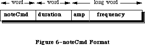 Figure 6–noteCmd Format
The param2 of a noteCmd is a combination of an amplitude and a frequency. The amplitude is passed in the high byte and the lower three bytes are the frequency . The frequency can be specified in two ways, as a decimal note
(refer to the section “Note Values and Durations”) or a frequency value (refer to freqCmd). The amplitude values range from $00 to $FF inclusively. The following example demonstrates the use of a noteCmd.
amp := $FF000000; {loudest possible amplitude}
note := 60; {middle C}
myCmd.cmd := noteCmd;
myCmd.param1 := 2000; {one second duration}
myCmd.param2 := amp + note;
myErr := SndDoCommand(myChan, myCmd, FALSE);
Note: The noteCmd will start at the beginning of a sampled sound. The
noteCmd uses the loop points of the header to extend the length of
the sound to the duration specified in a noteCmd. There must be a
loop ending point specified in the header in order for the noteCmd
to work properly.
Warning: Refer to the section “Current Sound Manager” regarding limitations
with the noteCmd and using amplitude.
cmd=restCmd param1=duration param2=0
This command is sent by applications and modifiers to cause the channel to rest for the duration specified in half-milliseconds.
cmd=freqCmd param1=0 param2=frequency
This command is sent by applications and modifiers. A frequency can be sent to a synthesizer to change the pitch of a sound. It is similar to the noteCmd in that a decimal note value can be used instead of a frequency value. The structure of this command is shown in Figure 7. If no sound is playing, it causes the synthesizer to begin playing at the specified frequency for an indefinite duration. The upper byte of param2 is ignored. A frequency value is sent in the lower three bytes of param2, where the frequency desired is multiplied by 256. For example, to specify a frequency of 440 Hz (the A below middle C) the frequency value would be 440 * 256 or 112640.
Figure 6–noteCmd Format
The param2 of a noteCmd is a combination of an amplitude and a frequency. The amplitude is passed in the high byte and the lower three bytes are the frequency . The frequency can be specified in two ways, as a decimal note
(refer to the section “Note Values and Durations”) or a frequency value (refer to freqCmd). The amplitude values range from $00 to $FF inclusively. The following example demonstrates the use of a noteCmd.
amp := $FF000000; {loudest possible amplitude}
note := 60; {middle C}
myCmd.cmd := noteCmd;
myCmd.param1 := 2000; {one second duration}
myCmd.param2 := amp + note;
myErr := SndDoCommand(myChan, myCmd, FALSE);
Note: The noteCmd will start at the beginning of a sampled sound. The
noteCmd uses the loop points of the header to extend the length of
the sound to the duration specified in a noteCmd. There must be a
loop ending point specified in the header in order for the noteCmd
to work properly.
Warning: Refer to the section “Current Sound Manager” regarding limitations
with the noteCmd and using amplitude.
cmd=restCmd param1=duration param2=0
This command is sent by applications and modifiers to cause the channel to rest for the duration specified in half-milliseconds.
cmd=freqCmd param1=0 param2=frequency
This command is sent by applications and modifiers. A frequency can be sent to a synthesizer to change the pitch of a sound. It is similar to the noteCmd in that a decimal note value can be used instead of a frequency value. The structure of this command is shown in Figure 7. If no sound is playing, it causes the synthesizer to begin playing at the specified frequency for an indefinite duration. The upper byte of param2 is ignored. A frequency value is sent in the lower three bytes of param2, where the frequency desired is multiplied by 256. For example, to specify a frequency of 440 Hz (the A below middle C) the frequency value would be 440 * 256 or 112640.
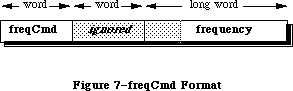 Figure 7–freqCmd format
Warning: Refer to the section “Current Sound Manager” regarding the
limitations of the freqCmd.
cmd=ampCmd param1=amplitude param2=0
This command is sent by applications and modifiers to change the amplitude of the sound in progress. If no sound is currently playing, then it will affect the amplitude of the next sound.
Warning: Refer to the section “Current Sound Manager” regarding the use of
amplitude.
cmd=timbreCmd param1=timbre param2=0
This command is sent by applications and modifiers. It is used only by the note synthesizer to change its timbre or tone. A sine wave is specified as 0 in param1 and produces a flute-like sound. A value of 255 in param1 represents a modified square wave and produces a buzzing or reed-like sound. Changing the note synthesizer’s timbre should be done before playing the sound. Only a Macintosh with the Apple Sound Chip will allow this command to be sent while a sound is in progress.
cmd=waveTableCmd param1=length param2=pointer
This command is sent by applications. It is only used by the wave table synthesizer. It will install a wave table to be used as an instrument by supplying a POINTER to the wave table in param2.
Note: All wave cycles will be re-sampled to 512 bytes.
cmd=phaseCmd param1=shift param2=pointer
This command is sent by applications. It is only used by the wave table synthesizer to synchronize the phases of the wave cycles across different wave table channels. As an example, if two wave table channels containing the same wave cycle were sent the same noteCmd, they could not begin exactly at the same time. Therefore, to synchronize the wave cycles for these two channels the phaseCmd is sent.
This prevents the phasing effects of playing two similar waves together at the same pitch. The channel will have its wave shifted by the amount specified in shift to correspond with the wave’s phase in the channel specified in param2. The shift value is a 16 bit fraction going from zero to one. The value of $8000 would be the half-way point of the wave cycle. Generally, the effects from this command will not be noticed.
Warning: Refer to the section “Current Sound Manager” regarding the phaseCmd.
cmd=soundCmd param1=0 param2=pointer
This command is sent by an application and is only used by the sampled sound synthesizer. If the application sends this command, param2 is a POINTER to the sampled sound locked in memory. The format of a sampled sound is shown in section “The Sampled Sound Synthesizer”. This command will install the sampled sound as an instrument for the channel. If the soundCmd is contained within a
'snd ' resource, the high bit of the command must be set. To use a sampled sound 'snd ' as an instrument , first obtain a POINTER to the sampled sound header locked in memory. Then pass this POINTER in param2 of a soundCmd. After using the sound, the application is expected to unlock this resource and allow it to be purged.
cmd=bufferCmd param1=0 param2=pointer
This command is sent by applications and the Sound Manager to play a sampled sound, in one-shot mode, without any looping. The POINTER in param2 is the location of a sampled sound header locked in memory. The format of a sampled sound is shown in section “The Sampled Sound Synthesizer”. A bufferCmd will be queued in the channel until the preceding commands have been processed. If the bufferCmd is contained within a 'snd ' resource, the high bit of the command must be set. If the sound was loaded in from a 'snd ' resource, the application is expected to unlock this resource and allow it to be purged after using it.
Warning: Refer to the section “Current Sound Manager” regarding the bufferCmd.
cmd=rateCmd param1=0 param2=rate
This command is sent by applications to modify the pitch of the sampled sound currently playing. The current pitch is multiplied by the rate in param2. It is used for pitch bending effects. The default rate of a channel is 1.0. To cause the pitch to fall an octave (or half of its frequency), send the rateCmd with param2 equal to one half as shown below.
myCmd.cmd := rateCmd;
myCmd.param1 := 0;
myCmd.param2 := FixedRatio(1, 2);
myErr := SndDoImmediate(myChan, myCmd);
cmd=continueCmd param1=0 param2=pointer
This command is sent by applications to the sampled sound synthesizer. It is similar to the bufferCmd. Long sampled sounds may be broken up into smaller sections. In this case, the application would use the bufferCmd for the first portion and the continueCmd for any remaining portions. This will result in a single continuous sound with the first byte of the sample being joined with the last byte of the previous sound header without audible clicks.
Warning: Refer to the section “Current Sound Manager” regarding the
continueCmd.
_______________________________________________________________________________
»USER ROUTINES
_______________________________________________________________________________
Warning: These user routines will be called at interrupt time and therefore
must not attempt to allocate, move or dispose of memory, de-reference
an unlocked handle, or call other routines that do so. Assembly
language programmers must preserve all registers other than A0-A1,
and D0-D2. If these routines are to use an application’s global
data storage, it must first reset A5 to the application’s A5 and
then restore it upon exit. Refer to Macintosh Technical Note #208
regarding setting up A5.
X-Ref: Technical Note #208
_______________________________________________________________________________
»PROCEDURE CallBack
(chan: SndChannelPtr; cmd: SndCommand);
The function _SndNewChannel allows a completion routine or CallBack procedure to be associated with a channel. This procedure will be called when a callBackCmd is received by the synthesizer linked to that channel. This procedure can be used for various purposes. Generally it is used by an application to determine that the channel has completed its commands and to dispose of the channel. The CallBack procedure itself cannot be used to dispose of the channel, since it may be called at interrupt time.
A CallBack procedure can also be used to signal that a channel has reached a certain point in the queue. An application may wish to perform particular actions based on how far along the sequence of commands a channel has processed. Applications can use param1 or param2 of the callBackCmd as flags. Based on certain flags for certain channels, the call back can perform many different functions. The CallBack procedure will be passed the channel that received the callBackCmd. The entire callBack command is also passed to the CallBack procedure.
myCmd.cmd := callBackCmd; {install the callBack command}
myCmd.param1 := 0; {not used in this example}
myCmd.param2 := SetCurrentA5; {pass the callBack our A5}
myErr := SndDoCommand (myChan, myCmd, FALSE);
The example code above is used to setup a callBackCmd. Note that param2 of a sound command is a LONGINT. This can be used to pass in the application’s A5 to the CallBack procedure. Once this command is received by the synthesizer, the following example CallBack procedure can set A5 in order to access the application’s globals. The function’s SetCurrentA5 and SetA5 are documented in Macintosh Technical Note #208.
Procedure SampleCallBack (theChan: SndChannelPtr; theCmd: SndCommand);
VAR
theA5 : LONGINT;
BEGIN
theA5 := SetA5(myCmd.param2); {set A5 and get current A5}
callBackPerformed := TRUE; {global flag}
theA5 := SetA5(theA5); {restore the current A5}
END;
_______________________________________________________________________________
»FUNCTION Modifier
(chan: SndChannelPtr; VAR cmd: SndCommand; mod: ModifierStubPtr) : BOOLEAN
A modifier will be called when the command reaches the end of the queue, before being sent to the synthesizer or other modifiers that may be installed. Chan will contain the channel pointer allowing multiple wave table channels to be supported by the same modifier. The ModifierStub is a record created by the Sound Manager during the call _SndAddModifier. A pointer to the ModifierStub is in mod. There are two special commands that the modifier must support, the initCmd and the freeCmd.
Warning: Refer to the section “Current Sound Manager” regarding modifiers
being saved as resources.
ModifierStub = PACKED RECORD
nextStub: ModifierStubPtr; {pointer to next stub}
code: ProcPtr; {pointer to modifier}
userInfo: LONGINT; {free for modifier’s use}
count: Time; {used internally}
every: Time; {used internally}
flags: SignedByte; {used internally}
hState: SignedByte; {used internally}
END;
The initCmd is sent by the Sound Manager when an application calls
_SndAddModifier. This is a command telling the modifier to allocate any additional data. The ModiferStub contains a four byte field, userInfo, that can be used as a pointer to this additional memory. The initCmd will not be sent to a modifier at interrupt time. This allows a modifier to allocate memory and save the current application’s A5. All memory storage allocated by the modifier must be locked, since the modifier will be called at interrupt time.
The freeCmd will be sent to the modifier when the Sound Manager is disposing of the channel. This command will not be sent at interrupt time. At this point the modifier should free any data it may have allocated.
A modifier will be given the current command, before the command is sent to the synthesizer or other modifiers. The current command is sent to the modifier in the variable cmd. A nullCmd is never sent to a modifier. If the modifier wished to ignore the current command and allow it to be sent on, it would return FALSE. To remove the current command, replace it with a nullCmd and then return FALSE. To alter the current command, replace it with the new one and return FALSE. Returning FALSE means that the modifier has completed its function.
If the modifier is to send additional commands to the channel, the function will return TRUE and may or may not change the current command. The Sound Manager will call the modifier again sending it a requestNextCmd. The modifier can then replace this command with the one desired. The modifier can continue to return TRUE to send additional commands. The requestNextCmd will indicate the number of times this command has been consecutively sent to the modifier.
Note: Modifiers are short routines used to perform real-time modifications on
channels. Having too many modifiers, or a lengthy one, may degrade
performance.
_______________________________________________________________________________
»THE CURRENT SOUND MANAGER
_______________________________________________________________________________
»Synthesizer Details
This section documents the details for each of the current synthesizers.
»The Note Synthesizer
• The version shipped with System 6.0.2 is $0001 0002.
• Commands currently supported:
availableCmd versionCmd freqCmd
noteCmd restCmd flushCmd
quietCmd ampCmd timbreCmd
»Limitations of the Note Synthesizer
• Amplitude change is only supported by a Macintosh with the Apple Sound
Chip, and is not supported by a Macintosh Plus or Macintosh SE.
• Only a single monophonic channel can be used.
»The Wave Table Synthesizer
• The version shipped with System 6.0.2 is $0001 0002.
• Commands currently supported:
availableCmd versionCmd freqCmd
noteCmd restCmd flushCmd
quietCmd waveTableCmd
»Limitations of the Wave Table Synthesizer
• This synthesizer is not functioning on a Macintosh Plus or Macintosh SE.
• A maximum of four channels can be open at any time.
• Amplitude change is not supported on any Macintosh.
• The one-shot mode is not supported on any Macintosh.
• The phaseCmd is not working.
»The Sampled Sound Synthesizer
• The version shipped with System 6.0.2 is $0001 0002.
• Commands currently supported:
availableCmd versionCmd freqCmd
noteCmd restCmd flushCmd
quietCmd rateCmd soundCmd
bufferCmd
»Limitations of the Sampled Sound Synthesizer
• Amplitude change is not supported on any Macintosh.
• The current hardware will only support sampling rates up to 22kHz. This
is not a limitation to the playback rates, and samples can be pitched
higher on playback.
• There can only be a single monophonic channel stereo is not supported.
• The continueCmd is not working.
»The MIDI Synthesizer
• The version shipped with System 6.0.2 is $0001 0002.
»Limitations of the MIDI Synthesizer
• The midiDataCmd cannot be used.
• Fully functional MIDI applications cannot be written using the current
Sound Manager and were intended as a “poor man’s” method of sending notes
to a MIDI keyboard.
• A bug in the MIDI synthesizer code prevents it from working after calling
_SndDisposeChannel.
_______________________________________________________________________________
»Sound Manager Bugs
This is a list of all known bugs and possible work-arounds in the System 6.0.2 Sound Manager. Each of these issues are being addressed and are expected to be solved with the next Sound Manager release.
Macintosh II 'snth' IDs
The System 6.0.2 'snth' resources for the Macintosh II are incorrectly numbered. They should be $0801-$0805, but were shipped as $0001-$0005. This does not currently present a problem for applications, since the Sound Manager will default to these versions while running on the Macintosh II.
availableCmd
The availableCmd is returning a value of 1, meaning TRUE, even if the synthesizer is actually no longer available. For example, after calling
_SndNewChannel for the noteSynth, the availableCmd for the noteSynth should return FALSE since there isn’t a second one. Furthermore, considering that only one synthesizer can be active at one time, after opening the noteSynth the sampledSynth is not available, but this command reports that it is. The only time the availableCmd will return FALSE is by requesting an init option that a synthesizer doesn't support, such as stereo channels.
_SndAddModifier
A modifier resource used in multiple channels must be pre-loaded and locked in memory by the application. There is a bug when the Sound Manager is disposing of a channel causing the modifier to be unlocked, regardless of other channels that may be using that modifier. If the application locks the modifier before installing it in the channel, the Sound Manager will not unlock it, but restores its state with _HSetState.
syncCmd
This command has a bug causing the count to be decremented incorrectly. To synchronize four channels, the same count = 4 should be sent to all channels. The bug is with the Sound Manager decrementing all of the count values with every new syncCmd. In order to work around this, an application can synchronize four wave table channels by sending the syncCmd with count = 4. Then a syncCmd with the same identifier is sent to the second channel, this time with count = 3. The third channel is sent a syncCmd with count = 2. Finally, the last channel is sent with the count = 1. As soon as the fourth syncCmd is received, all channels will have their count at 0 and will resume processing their queued commands. This bug will be fixed eventually, so test for the version of the synthesizer being used before relying on this.
bufferCmd
Sending a bufferCmd will reset the channel’s amplitude and rate settings. Since the amplitude is already being ignored and the rate isn't typically used, this problem is not of much concern at this time.
noteCmd
This command may cause the sampled sound synthesizer to loop until another command is sent to the channel. This occurs when using a sampled sound installed as an instrument. If a noteCmd is the last command in the channel, the sound will loop endlessly. The work-around is to send a command after the final noteCmd. A callBackCmd, restCmd or quietCmd would be good.
noteCmd and freqCmd
These commands currently only support note values 1 through 127 inclusive. Refer to Table 4 for these values.
_SysBeep
On a Macintosh Plus or SE (which do not have the Apple Sound Chip) the Sound Manager will purge the application’s channel of its 'snth' or sound data. The application would have to dispose of the channel at this point and recreate a new one. This is another reason to release channels as soon as the application has completed its sound. This bug can be avoided by selecting the “Simple Beep” in the Control Panel’s sound 'cdev'. Applications should dispose of all channels before allowing a _SysBeep to occur. This includes putting up an alert or modal dialog that could cause the system beep. Since a foreground application under MultiFinder could cause a _SysBeep while the sound application is in the background, all applications should dispose of channels at a suspend event.
_______________________________________________________________________________
»SOUND MANAGER ABUSE
_______________________________________________________________________________
Sound channels are for temporary use, and should only be created just before playing sound. Once the sound is completed, the channel should be disposed. Applications should not hold on to these channels for extended periods. The amount of overhead in _SndNewChannel is minimal. Basically, it is only a Memory Manager call. As long as the application holds onto a channel linked to a synthesizer, the _SysBeep call will not work and may cause trouble for the application’s channel.
Friendly applications will dispose of all open channels during a suspend event from MultiFinder. If an application created a channel and then gets sent into the background, any foreground application or _SysBeep will be unable to gain access to the sound hardware.
Applications must dispose of all channels before calling _ExitToShell. Currently, calling _ExitToShell while generating a sound on the Macintosh Plus and SE will cause a system crash. So, calling _SndDisposeChannel before
_ExitToShell will solve this issue. Setting quietNow to be FALSE will allow the application to complete the sound before continuing.
Do not mix older Sound Driver calls with the newer Sound Manager routines. The older Sound Driver should no longer be used. The Sound Manager is its replacement, providing all of it predecessor’s abilities and more. Note that
_GetSoundVol and _SetSoundVol are not part of the Sound Manager. They are used for setting parameter RAM, not the amplitude of a channel. Support for the older Sound Driver may eventually be discontinued.
The 'snd ' resource is so flexible that a warning of resource usage is needed. Most of the problems developers have with the Sound Manager are related more to the 'snd ' being used and less to the actual routines. Editing and creating
'snd ' resources with ResEdit is difficult. Many of the issues required in dealing with a 'snd ' are not supported by third party utilities. It is best to limit the 'snd ' to contain either sound data (i.e. sample sound) or a sequence of sound commands. Do not attempt to create resources that contain multiple sets of sound data.
Be very careful with what 'snd ' resources the application is intending to support. Test for the proper format and proper fields beforehand. An application needs to know the exact contents of the entire 'snd ' in order to properly handle it. Things can get ugly real quick considering variant records, variable record lengths, and the pointer math that will be required.
If an application wants to use _SndPlay with an existing channel already linked to a synthesizer, the 'snd ' must not contain any synth information. With a format 1 'snd ', the number of synth/modifiers field must be 0, and no synth ID or init option should be in the resource. Applications can only call _SndPlay with a channel linked to a synthesizer using a format 1 'snd ' that contains sound commands without synth information.
A format 2 'snd ' can never be used with _SndPlay more than once with an existing channel. This 'snd ' is assumed to be for the sampled sound synthesizer and _SndPlay will link this synthesizer to the channel. If a channel is created before calling _SndPlay with a format 2, specify synth = 0 in the call to _SndNewChannel. After calling _SndPlay once, the application will have to dispose of the channel before using a format 2 'snd ' again.
_______________________________________________________________________________
»FREQUENTLY ASKED QUESTIONS
_______________________________________________________________________________
Q: Is there a way to determine if a sound is being made?
A: It is not possible at this time to determine if a synthesizer is currently
active or producing a sound. However, an application can use the
callBackCmd to determine when a sound has completed.
Q: How do I determine if the Apple Sound Chip is present?
A: There is no supported method for determining this. A new _SysEnvirons
record is being considered to contain this information.
Q: How can I use the Sound Manager for a metronome effect?
A: Use a modifier to send a noteCmd to the note synthesizer. The modifier
will use the howOftenCmd to cause the Sound Manager to send a tickleCmd.
Every time the modifier gets called, it can send a noteCmd to cause the
click.
Q: What is the maximum number of synthesizers that can be opened at once?
Can I have the noteSynth and the sampledSynth open at the same time and
produce sound from either?
A: Only one synthesizer can be active at any time. This is because the active
synthesizer “owns” the sound hardware until the channel is disposed of.
Q: How can I tell if more than four wave table channels are open or if another
application has already open a synthesizer?
A: It is not possible at this time to determine when more than the maximum
number of wave table channels has been allocated due to a limitation with
the availableCmd. This issue is being investigated. It is not possible
to determine if a synthesizer is in use by another application. If all
applications would dispose of their channels at the resume event, this
would not be a problem.
Q: How do I get _SndPlay to play the sound asynchronously? The Sound Manager
seems to ignore the async parameter.
A: If NIL is used for the channel, then _SndPlay does ignore the async flag.
To play the sound asynchronously, create a new channel with _SndNewChannel
and pass this channel’s pointer to _SndPlay. Again, if this 'snd '
contains 'snth' information you must not link a synthesizer to the channel.
Pass 0 as the synth in the call to _SndNewChannel.
Q: Should we use 'snd ' format 1 or format 2 for creating sound resources?
A: The format 1 'snd ' is much more versatile. It can be used in the _SndPlay
routine for any synthesizer and requires minimal programming effort. There
is no recommendation for using either format. A format 1 has more
advantages, and may contain everything a format 2 does. A format 2 is for
a sampled sound only.
Q: I’ve opened a channel for the sampled sound synthesizer and I’m using
_SndPlay. After awhile the system either hangs or crashes. What’s wrong?
A: This is the most common abuse of the Sound Manager. The 'snd ' being used
has specified a 'snth' resource (a format 2 'snd ' is assumed for the
sampled sound synthesizer). The Sound Manager will attempt to link this
'snth' to the channel with every call to _SndPlay. What’s wrong is that
the synthesizer has already been installed and the Sound Manager is
attempting to install it again, only this time as a modifier. The same
'snth' code has been install more than once in the channel. If the 'snd '
contains 'snth' information, then _SndPlay can be used once and only once
on a channel. There two possible solutions: Do the pointer math to obtain
the sampled sound header and use the bufferCmd, or dispose of the channel
after each call to _SndPlay.
Q: How can I use a sampled sound to play a sequence of notes?
A: Begin by opening a sampled sound channel. Load and lock the 'snd '
resource containing the sample sound into memory. Then obtain a pointer
to the sampled sound header. Pass this pointer to the channel using the
soundCmd. Now the sound is installed and ready for a sequence of noteCmds.
This sampled sound must contain an ending loop point or the noteCmd may
not be heard.
Q: How do I change the play back rate of a sampled sound? Do I use the
freqCmd or the rateCmd?
A: It is possible to change the sampling rate contained in the sampled sound
header and then use the bufferCmd. The freqCmd currently requires decimal
note values and will not support real frequency values. The rateCmd will
only affect a sound that is currently in progress and is used for pitch
bending effects. It is possible to add a few bytes of silence to the
beginning of the sample to allow the rateCmd enough time to adjust the play
back rate without hearing the bending affect on its pitch.
Q: How can I play multiple sampled sounds to play as a single sampled sound
without the glitch that is heard between each sample on the Mac Plus?
A: On the Macintosh Plus or SE, the Sound Manager uses a 370 byte buffer
internally to play sampled sounds. If the array of sampled sound data is
in multiples of 370 bytes, the Sound Manager will not have to pad its
internal buffer with silence. Using double buffering techniques, an
application can send multiple sampled sounds using the bufferCmd from a
CallBack procedure to create a continuous sound. Use this technique until
the continueCmd is supported.
Q: How can I use the MIDI synthesizers with my own keyboards?
A: They have too many limitations at this time. Don’t bother trying.
_______________________________________________________________________________
»NOTE VALUES AND DURATIONS
_______________________________________________________________________________
Tempo in beats/min 30 60 90 120 150 180
whole note 16000 8000 5333 4000 3200 2667
half note 8000 4000 2667 2000 1600 1333
dotted quarter note 6000 3000 2000 1500 1200 1000
quarter note 4000 2000 1333 1000 800 667
dotted eighth note 3000 1500 1000 750 600 500
eighth note 2000 1000 667 500 400 333
dotted sixteenth note 1500 750 500 375 300 250
sixteenth note 1000 500 333 250 200 167
Table 3–duration values
Table 3 shows the duration values that are used in a waitCmd, howOftenCmd, wakeUpCmd, noteCmd, and restCmd. Their duration is in half-millisecond values. This chart will help in determining the actual duration used in certain tempos. To calculate the duration use the following formula.
duration = (2000/(beats per minute/60)) * beats per note
To calculate the duration for a note at a given tempo, divide the beats per minute by 60 to get the number of beats per second. Then divide the beats per second into 2000, which is the number of half-milliseconds in a second. Multiply this ratio with the number of beats the note should receive. For example, in a 4/4 time signature each sixteenth note receives 1/4th of a beat. If an application is playing a song in 120 beats per minute and wanted four sixteenth notes, each noteCmd would have a duration of 250.
A A# B C C# D D# E F F# G G#
Octave 1 1 2 3 4 5 6 7 8
Octave 2 9 10 11 12 13 14 15 16 17 18 19 20
Octave 3 21 22 23 24 25 26 27 28 29 30 31 32
Octave 4 33 34 35 36 37 38 39 40 41 42 43 44
Octave 5 45 46 47 48 49 50 51 52 53 54 55 56
Octave 6 57 58 59 60 61 62 63 64 65 66 67 68
Octave 7 69 70 71 72 73 74 75 76 77 78 79 80
Octave 8 81 82 83 84 85 86 87 88 89 90 91 92
Octave 9 93 94 95 96 97 98 99 100 101 102 103 104
Octave 10 105 106 107 108 109 110 111 112 113 114 115 116
Octave 11 117 118 119 120 121 122 123 124 125 126 127
Table 4–noteCmd values
Table 4 shows the values that can be sent with a noteCmd. Middle C is represented by a value of 60. These values correspond to MIDI note values.
_______________________________________________________________________________
»SUMMARY OF THE SOUND MANAGER
_______________________________________________________________________________
Constants
CONST
{ sound command numbers }
nullCmd = 0; {utility generally sent by Sound Manager}
initCmd = 1; {utility generally sent by Sound Manager}
freeCmd = 2; {utility generally sent by Sound Manager}
quietCmd = 3; {utility generally sent by Sound Manager}
flushCmd = 4; {utility generally sent by Sound Manager}
waitCmd = 10; {sync control sent by application or modifier}
pauseCmd = 11; {sync control sent by application or modifier}
resumeCmd = 12; {sync control sent by application or modifier}
callBackCmd = 13; {sync control sent by application or modifier}
syncCmd = 14; {sync control sent by application or modifier}
emptyCmd = 15; {sync control sent by application or modifier}
tickleCmd = 20; {utility sent by Sound Manager or modifier}
requestNextCmd = 21; {utility sent by Sound Manager or modifier}
howOftenCmd = 22; {utility sent by Sound Manager or modifier}
wakeUpCmd = 23; {utility sent by Sound Manager or modifier}
availableCmd = 24; {utility sent by application}
versionCmd = 25; {utility sent by application}
noteCmd = 40; {basic command supported by all synthesizers}
restCmd = 41; {basic command supported by all synthesizers}
freqCmd = 42; {basic command supported by all synthesizers}
ampCmd = 43; {basic command supported by all synthesizers}
timbreCmd = 44; {noteSynth only}
waveTableCmd = 60; {waveTableSynth only}
phaseCmd = 61; {waveTableSynth only}
soundCmd = 80; {sampledSynth only}
bufferCmd = 81; {sampledSynth only}
rateCmd = 82; {sampledSynth only}
continueCmd = 83; {sampledSynth only}
{ synthesizer resource IDs used with _SndNewChannel }
noteSynth = 1; {note synthesizer}
waveTableSynth = 3; {wave table synthesizer}
sampledSynth = 5; {MIDI synthesizer in}
midiSynthIn = 7; {MIDI synthesizer in}
midiSynthOut = 9; {MIDI synthesizer out}
{ init options used with _SndNewChannel }
initChanLeft = $02; {left channel - sampleSynth only}
initChanRight = $03; {right channel- sampleSynth only}
initChan0 = $04; {channel 0 - wave table only}
initChan1 = $05; {channel 1 - wave table only}
initChan2 = $06; {channel 2 - wave table only}
initChan3 = $07; {channel 3 - wave table only}
initSRate22k = $20; {22k sampling rate - sampleSynth only}
initSRate44k = $30; {44k sampling rate - sampleSynth only}
initMono = $80; {monophonic channel - sampleSynth only}
initStereo = $C0; {stereo channel - sampleSynth only}
stdQLength = 128; {channel length for holding 128 commands}
{ sample encoding options }
stdSH = $00 {standard sound header}
extSH = $01 {extended sound header}
cmpSH = $02 {compressed sound header}
{ Sound Manager error codes }
noErr = 0 {no error}
noHardware = -200 {no hardware to support synthesizer}
notEnoughHardware = -201 {no more channels to support synthesizer}
queueFull = -203 {no room left in the channel}
resProblem = -204 {problem loading the resource}
badChannel = -205 {invalid channel}
badFormat = -206 {handle to snd resource was invalid}
_______________________________________________________________________________
Data Types
TYPE
Time = LONGINT;
SndCommand = PACKED RECORD
cmd: INTEGER; {command number}
param1: INTEGER; {first parameter}
param2: LONGINT; {second parameter}
END;
ModifierStubPtr = ^ModifierStub;
ModifierStub = PACKED RECORD
nextStub: ModifierStubPtr; {pointer to next stub}
code: ProcPtr; {pointer to modifier}
userInfo: LONGINT; {free for modifier’s use}
count: Time; {used internally}
every: Time; {used internally}
flags: SignedByte; {used internally}
hState: SignedByte; {used internally}
END;
SndChannelPtr = ^SndChannel;
SndChannel = PACKED RECORD
nextChan: SndChannelPtr; {pointer to next channel}
firstMod: ModifierStubPtr; {ptr to first modifier}
callBack: ProcPtr; {ptr to call back procedure}
userInfo: LONGINT; {free for application’s use}
wait: Time; {used internally}
cmdInProgress: SndCommand; {used internally}
flags: INTEGER; {used internally}
qLength: INTEGER; {used internally}
qHead: INTEGER; {used internally}
qTail: INTEGER; {used internally}
queue: ARRAY [0..stdQLength-1] OF SndCommand;
END;
SoundHeaderPtr = ^SoundHeader;
SoundHeader = PACKED RECORD {sampled sound header}
samplePtr: Ptr; {NIL if samples in sampleArea}
length: LONGINT; {number of samples in array}
sampleRate: Fixed; {sampling rate}
loopStart: LONGINT; {loop point beginning}
loopEnd: LONGINT; {loop point ending}
encode: BYTE; {sample's encoding option}
baseNote: BYTE; {base note of sample}
sampleArea: PACKED ARRAY [0..0] OF Byte;
END;
{refer to the Audio Interchange File Format “AIFF” specification}
ExtSoundHeaderPtr = ^ExtSoundHeader;
ExtSoundHeader = PACKED RECORD {extended sample header}
samplePtr: Ptr; {NIL if samples in }
{ sampleArea}
length: LONGINT; {number of sample frames}
sampleRate: Fixed; {rate of original sample}
loopStart: LONGINT; {loop point beginning}
loopEnd: LONGINT; {loop point ending}
encode: BYTE; {sample's encoding option}
baseNote: BYTE; {base note of original }
{ sample}
numChannels: INTEGER; {number of chans used in }
{ sample}
sampleSize: INTEGER; {bits in each sample point}
AIFFSampleRate: EXTENDED; {rate of original sample}
MarkerChunk: Ptr; {pointer to a marker info}
InstrumentChunks: Ptr; {pointer to instrument info}
AESRecording: Ptr; {pointer to audio info}
FutureUse1: LONGINT;
FutureUse2: LONGINT;
FutureUse3: LONGINT;
FutureUse4: LONGINT;
sampleArea: PACKED ARRAY [0..0] OF Byte;
END;
_______________________________________________________________________________
Routines
FUNCTION SndDoCommand (chan: SndChannelPtr; cmd: SndCommand;
noWait: BOOLEAN): OSErr;
INLINE $A803;
FUNCTION SndDoImmediate (chan: SndChannelPtr; cmd: SndCommand): OSErr;
INLINE $A804;
FUNCTION SndNewChannel (VAR chan: SndChannelPtr; synth: INTEGER;
init: LONGINT; userRoutine: ProcPtr): OSErr;
INLINE $A807;
FUNCTION SndDisposeChannel (chan: SndChannelPtr; quietNow: BOOLEAN): OSErr;
INLINE $A801;
FUNCTION SndPlay (chan: SndChannelPtr; sndHdl: Handle;
async: BOOLEAN): OSErr;
INLINE $A805;
FUNCTION SndControl (id: INTEGER; VAR cmd: SndCommand): OSErr;
INLINE $A806;
FUNCTION SndAddModifier (chan: SndChannelPtr; modifier: ProcPtr;
id: INTEGER; init: LONGINT): OSErr;
INLINE $A802;
PROCEDURE MyCallBack (chan: SndChannelPtr; cmd: SndCommand);
FUNCTION MyModifier (chan: SndChannelPtr; VAR cmd: SndCommand;
mod: ModifierStub): BOOLEAN;
Further Reference:
_______________________________________________________________________________
Resource Manager
User Interface Guidelines
OS Utilities
Technical Note #19, How To Produce Continuous Sound Without Clicking
Technical Note #168, HyperCard ‘snd ’ Resources
Technical Note #208, Setting and Restoring A5
“Macintosh Family Hardware Reference”
Figure 7–freqCmd format
Warning: Refer to the section “Current Sound Manager” regarding the
limitations of the freqCmd.
cmd=ampCmd param1=amplitude param2=0
This command is sent by applications and modifiers to change the amplitude of the sound in progress. If no sound is currently playing, then it will affect the amplitude of the next sound.
Warning: Refer to the section “Current Sound Manager” regarding the use of
amplitude.
cmd=timbreCmd param1=timbre param2=0
This command is sent by applications and modifiers. It is used only by the note synthesizer to change its timbre or tone. A sine wave is specified as 0 in param1 and produces a flute-like sound. A value of 255 in param1 represents a modified square wave and produces a buzzing or reed-like sound. Changing the note synthesizer’s timbre should be done before playing the sound. Only a Macintosh with the Apple Sound Chip will allow this command to be sent while a sound is in progress.
cmd=waveTableCmd param1=length param2=pointer
This command is sent by applications. It is only used by the wave table synthesizer. It will install a wave table to be used as an instrument by supplying a POINTER to the wave table in param2.
Note: All wave cycles will be re-sampled to 512 bytes.
cmd=phaseCmd param1=shift param2=pointer
This command is sent by applications. It is only used by the wave table synthesizer to synchronize the phases of the wave cycles across different wave table channels. As an example, if two wave table channels containing the same wave cycle were sent the same noteCmd, they could not begin exactly at the same time. Therefore, to synchronize the wave cycles for these two channels the phaseCmd is sent.
This prevents the phasing effects of playing two similar waves together at the same pitch. The channel will have its wave shifted by the amount specified in shift to correspond with the wave’s phase in the channel specified in param2. The shift value is a 16 bit fraction going from zero to one. The value of $8000 would be the half-way point of the wave cycle. Generally, the effects from this command will not be noticed.
Warning: Refer to the section “Current Sound Manager” regarding the phaseCmd.
cmd=soundCmd param1=0 param2=pointer
This command is sent by an application and is only used by the sampled sound synthesizer. If the application sends this command, param2 is a POINTER to the sampled sound locked in memory. The format of a sampled sound is shown in section “The Sampled Sound Synthesizer”. This command will install the sampled sound as an instrument for the channel. If the soundCmd is contained within a
'snd ' resource, the high bit of the command must be set. To use a sampled sound 'snd ' as an instrument , first obtain a POINTER to the sampled sound header locked in memory. Then pass this POINTER in param2 of a soundCmd. After using the sound, the application is expected to unlock this resource and allow it to be purged.
cmd=bufferCmd param1=0 param2=pointer
This command is sent by applications and the Sound Manager to play a sampled sound, in one-shot mode, without any looping. The POINTER in param2 is the location of a sampled sound header locked in memory. The format of a sampled sound is shown in section “The Sampled Sound Synthesizer”. A bufferCmd will be queued in the channel until the preceding commands have been processed. If the bufferCmd is contained within a 'snd ' resource, the high bit of the command must be set. If the sound was loaded in from a 'snd ' resource, the application is expected to unlock this resource and allow it to be purged after using it.
Warning: Refer to the section “Current Sound Manager” regarding the bufferCmd.
cmd=rateCmd param1=0 param2=rate
This command is sent by applications to modify the pitch of the sampled sound currently playing. The current pitch is multiplied by the rate in param2. It is used for pitch bending effects. The default rate of a channel is 1.0. To cause the pitch to fall an octave (or half of its frequency), send the rateCmd with param2 equal to one half as shown below.
myCmd.cmd := rateCmd;
myCmd.param1 := 0;
myCmd.param2 := FixedRatio(1, 2);
myErr := SndDoImmediate(myChan, myCmd);
cmd=continueCmd param1=0 param2=pointer
This command is sent by applications to the sampled sound synthesizer. It is similar to the bufferCmd. Long sampled sounds may be broken up into smaller sections. In this case, the application would use the bufferCmd for the first portion and the continueCmd for any remaining portions. This will result in a single continuous sound with the first byte of the sample being joined with the last byte of the previous sound header without audible clicks.
Warning: Refer to the section “Current Sound Manager” regarding the
continueCmd.
_______________________________________________________________________________
»USER ROUTINES
_______________________________________________________________________________
Warning: These user routines will be called at interrupt time and therefore
must not attempt to allocate, move or dispose of memory, de-reference
an unlocked handle, or call other routines that do so. Assembly
language programmers must preserve all registers other than A0-A1,
and D0-D2. If these routines are to use an application’s global
data storage, it must first reset A5 to the application’s A5 and
then restore it upon exit. Refer to Macintosh Technical Note #208
regarding setting up A5.
X-Ref: Technical Note #208
_______________________________________________________________________________
»PROCEDURE CallBack
(chan: SndChannelPtr; cmd: SndCommand);
The function _SndNewChannel allows a completion routine or CallBack procedure to be associated with a channel. This procedure will be called when a callBackCmd is received by the synthesizer linked to that channel. This procedure can be used for various purposes. Generally it is used by an application to determine that the channel has completed its commands and to dispose of the channel. The CallBack procedure itself cannot be used to dispose of the channel, since it may be called at interrupt time.
A CallBack procedure can also be used to signal that a channel has reached a certain point in the queue. An application may wish to perform particular actions based on how far along the sequence of commands a channel has processed. Applications can use param1 or param2 of the callBackCmd as flags. Based on certain flags for certain channels, the call back can perform many different functions. The CallBack procedure will be passed the channel that received the callBackCmd. The entire callBack command is also passed to the CallBack procedure.
myCmd.cmd := callBackCmd; {install the callBack command}
myCmd.param1 := 0; {not used in this example}
myCmd.param2 := SetCurrentA5; {pass the callBack our A5}
myErr := SndDoCommand (myChan, myCmd, FALSE);
The example code above is used to setup a callBackCmd. Note that param2 of a sound command is a LONGINT. This can be used to pass in the application’s A5 to the CallBack procedure. Once this command is received by the synthesizer, the following example CallBack procedure can set A5 in order to access the application’s globals. The function’s SetCurrentA5 and SetA5 are documented in Macintosh Technical Note #208.
Procedure SampleCallBack (theChan: SndChannelPtr; theCmd: SndCommand);
VAR
theA5 : LONGINT;
BEGIN
theA5 := SetA5(myCmd.param2); {set A5 and get current A5}
callBackPerformed := TRUE; {global flag}
theA5 := SetA5(theA5); {restore the current A5}
END;
_______________________________________________________________________________
»FUNCTION Modifier
(chan: SndChannelPtr; VAR cmd: SndCommand; mod: ModifierStubPtr) : BOOLEAN
A modifier will be called when the command reaches the end of the queue, before being sent to the synthesizer or other modifiers that may be installed. Chan will contain the channel pointer allowing multiple wave table channels to be supported by the same modifier. The ModifierStub is a record created by the Sound Manager during the call _SndAddModifier. A pointer to the ModifierStub is in mod. There are two special commands that the modifier must support, the initCmd and the freeCmd.
Warning: Refer to the section “Current Sound Manager” regarding modifiers
being saved as resources.
ModifierStub = PACKED RECORD
nextStub: ModifierStubPtr; {pointer to next stub}
code: ProcPtr; {pointer to modifier}
userInfo: LONGINT; {free for modifier’s use}
count: Time; {used internally}
every: Time; {used internally}
flags: SignedByte; {used internally}
hState: SignedByte; {used internally}
END;
The initCmd is sent by the Sound Manager when an application calls
_SndAddModifier. This is a command telling the modifier to allocate any additional data. The ModiferStub contains a four byte field, userInfo, that can be used as a pointer to this additional memory. The initCmd will not be sent to a modifier at interrupt time. This allows a modifier to allocate memory and save the current application’s A5. All memory storage allocated by the modifier must be locked, since the modifier will be called at interrupt time.
The freeCmd will be sent to the modifier when the Sound Manager is disposing of the channel. This command will not be sent at interrupt time. At this point the modifier should free any data it may have allocated.
A modifier will be given the current command, before the command is sent to the synthesizer or other modifiers. The current command is sent to the modifier in the variable cmd. A nullCmd is never sent to a modifier. If the modifier wished to ignore the current command and allow it to be sent on, it would return FALSE. To remove the current command, replace it with a nullCmd and then return FALSE. To alter the current command, replace it with the new one and return FALSE. Returning FALSE means that the modifier has completed its function.
If the modifier is to send additional commands to the channel, the function will return TRUE and may or may not change the current command. The Sound Manager will call the modifier again sending it a requestNextCmd. The modifier can then replace this command with the one desired. The modifier can continue to return TRUE to send additional commands. The requestNextCmd will indicate the number of times this command has been consecutively sent to the modifier.
Note: Modifiers are short routines used to perform real-time modifications on
channels. Having too many modifiers, or a lengthy one, may degrade
performance.
_______________________________________________________________________________
»THE CURRENT SOUND MANAGER
_______________________________________________________________________________
»Synthesizer Details
This section documents the details for each of the current synthesizers.
»The Note Synthesizer
• The version shipped with System 6.0.2 is $0001 0002.
• Commands currently supported:
availableCmd versionCmd freqCmd
noteCmd restCmd flushCmd
quietCmd ampCmd timbreCmd
»Limitations of the Note Synthesizer
• Amplitude change is only supported by a Macintosh with the Apple Sound
Chip, and is not supported by a Macintosh Plus or Macintosh SE.
• Only a single monophonic channel can be used.
»The Wave Table Synthesizer
• The version shipped with System 6.0.2 is $0001 0002.
• Commands currently supported:
availableCmd versionCmd freqCmd
noteCmd restCmd flushCmd
quietCmd waveTableCmd
»Limitations of the Wave Table Synthesizer
• This synthesizer is not functioning on a Macintosh Plus or Macintosh SE.
• A maximum of four channels can be open at any time.
• Amplitude change is not supported on any Macintosh.
• The one-shot mode is not supported on any Macintosh.
• The phaseCmd is not working.
»The Sampled Sound Synthesizer
• The version shipped with System 6.0.2 is $0001 0002.
• Commands currently supported:
availableCmd versionCmd freqCmd
noteCmd restCmd flushCmd
quietCmd rateCmd soundCmd
bufferCmd
»Limitations of the Sampled Sound Synthesizer
• Amplitude change is not supported on any Macintosh.
• The current hardware will only support sampling rates up to 22kHz. This
is not a limitation to the playback rates, and samples can be pitched
higher on playback.
• There can only be a single monophonic channel stereo is not supported.
• The continueCmd is not working.
»The MIDI Synthesizer
• The version shipped with System 6.0.2 is $0001 0002.
»Limitations of the MIDI Synthesizer
• The midiDataCmd cannot be used.
• Fully functional MIDI applications cannot be written using the current
Sound Manager and were intended as a “poor man’s” method of sending notes
to a MIDI keyboard.
• A bug in the MIDI synthesizer code prevents it from working after calling
_SndDisposeChannel.
_______________________________________________________________________________
»Sound Manager Bugs
This is a list of all known bugs and possible work-arounds in the System 6.0.2 Sound Manager. Each of these issues are being addressed and are expected to be solved with the next Sound Manager release.
Macintosh II 'snth' IDs
The System 6.0.2 'snth' resources for the Macintosh II are incorrectly numbered. They should be $0801-$0805, but were shipped as $0001-$0005. This does not currently present a problem for applications, since the Sound Manager will default to these versions while running on the Macintosh II.
availableCmd
The availableCmd is returning a value of 1, meaning TRUE, even if the synthesizer is actually no longer available. For example, after calling
_SndNewChannel for the noteSynth, the availableCmd for the noteSynth should return FALSE since there isn’t a second one. Furthermore, considering that only one synthesizer can be active at one time, after opening the noteSynth the sampledSynth is not available, but this command reports that it is. The only time the availableCmd will return FALSE is by requesting an init option that a synthesizer doesn't support, such as stereo channels.
_SndAddModifier
A modifier resource used in multiple channels must be pre-loaded and locked in memory by the application. There is a bug when the Sound Manager is disposing of a channel causing the modifier to be unlocked, regardless of other channels that may be using that modifier. If the application locks the modifier before installing it in the channel, the Sound Manager will not unlock it, but restores its state with _HSetState.
syncCmd
This command has a bug causing the count to be decremented incorrectly. To synchronize four channels, the same count = 4 should be sent to all channels. The bug is with the Sound Manager decrementing all of the count values with every new syncCmd. In order to work around this, an application can synchronize four wave table channels by sending the syncCmd with count = 4. Then a syncCmd with the same identifier is sent to the second channel, this time with count = 3. The third channel is sent a syncCmd with count = 2. Finally, the last channel is sent with the count = 1. As soon as the fourth syncCmd is received, all channels will have their count at 0 and will resume processing their queued commands. This bug will be fixed eventually, so test for the version of the synthesizer being used before relying on this.
bufferCmd
Sending a bufferCmd will reset the channel’s amplitude and rate settings. Since the amplitude is already being ignored and the rate isn't typically used, this problem is not of much concern at this time.
noteCmd
This command may cause the sampled sound synthesizer to loop until another command is sent to the channel. This occurs when using a sampled sound installed as an instrument. If a noteCmd is the last command in the channel, the sound will loop endlessly. The work-around is to send a command after the final noteCmd. A callBackCmd, restCmd or quietCmd would be good.
noteCmd and freqCmd
These commands currently only support note values 1 through 127 inclusive. Refer to Table 4 for these values.
_SysBeep
On a Macintosh Plus or SE (which do not have the Apple Sound Chip) the Sound Manager will purge the application’s channel of its 'snth' or sound data. The application would have to dispose of the channel at this point and recreate a new one. This is another reason to release channels as soon as the application has completed its sound. This bug can be avoided by selecting the “Simple Beep” in the Control Panel’s sound 'cdev'. Applications should dispose of all channels before allowing a _SysBeep to occur. This includes putting up an alert or modal dialog that could cause the system beep. Since a foreground application under MultiFinder could cause a _SysBeep while the sound application is in the background, all applications should dispose of channels at a suspend event.
_______________________________________________________________________________
»SOUND MANAGER ABUSE
_______________________________________________________________________________
Sound channels are for temporary use, and should only be created just before playing sound. Once the sound is completed, the channel should be disposed. Applications should not hold on to these channels for extended periods. The amount of overhead in _SndNewChannel is minimal. Basically, it is only a Memory Manager call. As long as the application holds onto a channel linked to a synthesizer, the _SysBeep call will not work and may cause trouble for the application’s channel.
Friendly applications will dispose of all open channels during a suspend event from MultiFinder. If an application created a channel and then gets sent into the background, any foreground application or _SysBeep will be unable to gain access to the sound hardware.
Applications must dispose of all channels before calling _ExitToShell. Currently, calling _ExitToShell while generating a sound on the Macintosh Plus and SE will cause a system crash. So, calling _SndDisposeChannel before
_ExitToShell will solve this issue. Setting quietNow to be FALSE will allow the application to complete the sound before continuing.
Do not mix older Sound Driver calls with the newer Sound Manager routines. The older Sound Driver should no longer be used. The Sound Manager is its replacement, providing all of it predecessor’s abilities and more. Note that
_GetSoundVol and _SetSoundVol are not part of the Sound Manager. They are used for setting parameter RAM, not the amplitude of a channel. Support for the older Sound Driver may eventually be discontinued.
The 'snd ' resource is so flexible that a warning of resource usage is needed. Most of the problems developers have with the Sound Manager are related more to the 'snd ' being used and less to the actual routines. Editing and creating
'snd ' resources with ResEdit is difficult. Many of the issues required in dealing with a 'snd ' are not supported by third party utilities. It is best to limit the 'snd ' to contain either sound data (i.e. sample sound) or a sequence of sound commands. Do not attempt to create resources that contain multiple sets of sound data.
Be very careful with what 'snd ' resources the application is intending to support. Test for the proper format and proper fields beforehand. An application needs to know the exact contents of the entire 'snd ' in order to properly handle it. Things can get ugly real quick considering variant records, variable record lengths, and the pointer math that will be required.
If an application wants to use _SndPlay with an existing channel already linked to a synthesizer, the 'snd ' must not contain any synth information. With a format 1 'snd ', the number of synth/modifiers field must be 0, and no synth ID or init option should be in the resource. Applications can only call _SndPlay with a channel linked to a synthesizer using a format 1 'snd ' that contains sound commands without synth information.
A format 2 'snd ' can never be used with _SndPlay more than once with an existing channel. This 'snd ' is assumed to be for the sampled sound synthesizer and _SndPlay will link this synthesizer to the channel. If a channel is created before calling _SndPlay with a format 2, specify synth = 0 in the call to _SndNewChannel. After calling _SndPlay once, the application will have to dispose of the channel before using a format 2 'snd ' again.
_______________________________________________________________________________
»FREQUENTLY ASKED QUESTIONS
_______________________________________________________________________________
Q: Is there a way to determine if a sound is being made?
A: It is not possible at this time to determine if a synthesizer is currently
active or producing a sound. However, an application can use the
callBackCmd to determine when a sound has completed.
Q: How do I determine if the Apple Sound Chip is present?
A: There is no supported method for determining this. A new _SysEnvirons
record is being considered to contain this information.
Q: How can I use the Sound Manager for a metronome effect?
A: Use a modifier to send a noteCmd to the note synthesizer. The modifier
will use the howOftenCmd to cause the Sound Manager to send a tickleCmd.
Every time the modifier gets called, it can send a noteCmd to cause the
click.
Q: What is the maximum number of synthesizers that can be opened at once?
Can I have the noteSynth and the sampledSynth open at the same time and
produce sound from either?
A: Only one synthesizer can be active at any time. This is because the active
synthesizer “owns” the sound hardware until the channel is disposed of.
Q: How can I tell if more than four wave table channels are open or if another
application has already open a synthesizer?
A: It is not possible at this time to determine when more than the maximum
number of wave table channels has been allocated due to a limitation with
the availableCmd. This issue is being investigated. It is not possible
to determine if a synthesizer is in use by another application. If all
applications would dispose of their channels at the resume event, this
would not be a problem.
Q: How do I get _SndPlay to play the sound asynchronously? The Sound Manager
seems to ignore the async parameter.
A: If NIL is used for the channel, then _SndPlay does ignore the async flag.
To play the sound asynchronously, create a new channel with _SndNewChannel
and pass this channel’s pointer to _SndPlay. Again, if this 'snd '
contains 'snth' information you must not link a synthesizer to the channel.
Pass 0 as the synth in the call to _SndNewChannel.
Q: Should we use 'snd ' format 1 or format 2 for creating sound resources?
A: The format 1 'snd ' is much more versatile. It can be used in the _SndPlay
routine for any synthesizer and requires minimal programming effort. There
is no recommendation for using either format. A format 1 has more
advantages, and may contain everything a format 2 does. A format 2 is for
a sampled sound only.
Q: I’ve opened a channel for the sampled sound synthesizer and I’m using
_SndPlay. After awhile the system either hangs or crashes. What’s wrong?
A: This is the most common abuse of the Sound Manager. The 'snd ' being used
has specified a 'snth' resource (a format 2 'snd ' is assumed for the
sampled sound synthesizer). The Sound Manager will attempt to link this
'snth' to the channel with every call to _SndPlay. What’s wrong is that
the synthesizer has already been installed and the Sound Manager is
attempting to install it again, only this time as a modifier. The same
'snth' code has been install more than once in the channel. If the 'snd '
contains 'snth' information, then _SndPlay can be used once and only once
on a channel. There two possible solutions: Do the pointer math to obtain
the sampled sound header and use the bufferCmd, or dispose of the channel
after each call to _SndPlay.
Q: How can I use a sampled sound to play a sequence of notes?
A: Begin by opening a sampled sound channel. Load and lock the 'snd '
resource containing the sample sound into memory. Then obtain a pointer
to the sampled sound header. Pass this pointer to the channel using the
soundCmd. Now the sound is installed and ready for a sequence of noteCmds.
This sampled sound must contain an ending loop point or the noteCmd may
not be heard.
Q: How do I change the play back rate of a sampled sound? Do I use the
freqCmd or the rateCmd?
A: It is possible to change the sampling rate contained in the sampled sound
header and then use the bufferCmd. The freqCmd currently requires decimal
note values and will not support real frequency values. The rateCmd will
only affect a sound that is currently in progress and is used for pitch
bending effects. It is possible to add a few bytes of silence to the
beginning of the sample to allow the rateCmd enough time to adjust the play
back rate without hearing the bending affect on its pitch.
Q: How can I play multiple sampled sounds to play as a single sampled sound
without the glitch that is heard between each sample on the Mac Plus?
A: On the Macintosh Plus or SE, the Sound Manager uses a 370 byte buffer
internally to play sampled sounds. If the array of sampled sound data is
in multiples of 370 bytes, the Sound Manager will not have to pad its
internal buffer with silence. Using double buffering techniques, an
application can send multiple sampled sounds using the bufferCmd from a
CallBack procedure to create a continuous sound. Use this technique until
the continueCmd is supported.
Q: How can I use the MIDI synthesizers with my own keyboards?
A: They have too many limitations at this time. Don’t bother trying.
_______________________________________________________________________________
»NOTE VALUES AND DURATIONS
_______________________________________________________________________________
Tempo in beats/min 30 60 90 120 150 180
whole note 16000 8000 5333 4000 3200 2667
half note 8000 4000 2667 2000 1600 1333
dotted quarter note 6000 3000 2000 1500 1200 1000
quarter note 4000 2000 1333 1000 800 667
dotted eighth note 3000 1500 1000 750 600 500
eighth note 2000 1000 667 500 400 333
dotted sixteenth note 1500 750 500 375 300 250
sixteenth note 1000 500 333 250 200 167
Table 3–duration values
Table 3 shows the duration values that are used in a waitCmd, howOftenCmd, wakeUpCmd, noteCmd, and restCmd. Their duration is in half-millisecond values. This chart will help in determining the actual duration used in certain tempos. To calculate the duration use the following formula.
duration = (2000/(beats per minute/60)) * beats per note
To calculate the duration for a note at a given tempo, divide the beats per minute by 60 to get the number of beats per second. Then divide the beats per second into 2000, which is the number of half-milliseconds in a second. Multiply this ratio with the number of beats the note should receive. For example, in a 4/4 time signature each sixteenth note receives 1/4th of a beat. If an application is playing a song in 120 beats per minute and wanted four sixteenth notes, each noteCmd would have a duration of 250.
A A# B C C# D D# E F F# G G#
Octave 1 1 2 3 4 5 6 7 8
Octave 2 9 10 11 12 13 14 15 16 17 18 19 20
Octave 3 21 22 23 24 25 26 27 28 29 30 31 32
Octave 4 33 34 35 36 37 38 39 40 41 42 43 44
Octave 5 45 46 47 48 49 50 51 52 53 54 55 56
Octave 6 57 58 59 60 61 62 63 64 65 66 67 68
Octave 7 69 70 71 72 73 74 75 76 77 78 79 80
Octave 8 81 82 83 84 85 86 87 88 89 90 91 92
Octave 9 93 94 95 96 97 98 99 100 101 102 103 104
Octave 10 105 106 107 108 109 110 111 112 113 114 115 116
Octave 11 117 118 119 120 121 122 123 124 125 126 127
Table 4–noteCmd values
Table 4 shows the values that can be sent with a noteCmd. Middle C is represented by a value of 60. These values correspond to MIDI note values.
_______________________________________________________________________________
»SUMMARY OF THE SOUND MANAGER
_______________________________________________________________________________
Constants
CONST
{ sound command numbers }
nullCmd = 0; {utility generally sent by Sound Manager}
initCmd = 1; {utility generally sent by Sound Manager}
freeCmd = 2; {utility generally sent by Sound Manager}
quietCmd = 3; {utility generally sent by Sound Manager}
flushCmd = 4; {utility generally sent by Sound Manager}
waitCmd = 10; {sync control sent by application or modifier}
pauseCmd = 11; {sync control sent by application or modifier}
resumeCmd = 12; {sync control sent by application or modifier}
callBackCmd = 13; {sync control sent by application or modifier}
syncCmd = 14; {sync control sent by application or modifier}
emptyCmd = 15; {sync control sent by application or modifier}
tickleCmd = 20; {utility sent by Sound Manager or modifier}
requestNextCmd = 21; {utility sent by Sound Manager or modifier}
howOftenCmd = 22; {utility sent by Sound Manager or modifier}
wakeUpCmd = 23; {utility sent by Sound Manager or modifier}
availableCmd = 24; {utility sent by application}
versionCmd = 25; {utility sent by application}
noteCmd = 40; {basic command supported by all synthesizers}
restCmd = 41; {basic command supported by all synthesizers}
freqCmd = 42; {basic command supported by all synthesizers}
ampCmd = 43; {basic command supported by all synthesizers}
timbreCmd = 44; {noteSynth only}
waveTableCmd = 60; {waveTableSynth only}
phaseCmd = 61; {waveTableSynth only}
soundCmd = 80; {sampledSynth only}
bufferCmd = 81; {sampledSynth only}
rateCmd = 82; {sampledSynth only}
continueCmd = 83; {sampledSynth only}
{ synthesizer resource IDs used with _SndNewChannel }
noteSynth = 1; {note synthesizer}
waveTableSynth = 3; {wave table synthesizer}
sampledSynth = 5; {MIDI synthesizer in}
midiSynthIn = 7; {MIDI synthesizer in}
midiSynthOut = 9; {MIDI synthesizer out}
{ init options used with _SndNewChannel }
initChanLeft = $02; {left channel - sampleSynth only}
initChanRight = $03; {right channel- sampleSynth only}
initChan0 = $04; {channel 0 - wave table only}
initChan1 = $05; {channel 1 - wave table only}
initChan2 = $06; {channel 2 - wave table only}
initChan3 = $07; {channel 3 - wave table only}
initSRate22k = $20; {22k sampling rate - sampleSynth only}
initSRate44k = $30; {44k sampling rate - sampleSynth only}
initMono = $80; {monophonic channel - sampleSynth only}
initStereo = $C0; {stereo channel - sampleSynth only}
stdQLength = 128; {channel length for holding 128 commands}
{ sample encoding options }
stdSH = $00 {standard sound header}
extSH = $01 {extended sound header}
cmpSH = $02 {compressed sound header}
{ Sound Manager error codes }
noErr = 0 {no error}
noHardware = -200 {no hardware to support synthesizer}
notEnoughHardware = -201 {no more channels to support synthesizer}
queueFull = -203 {no room left in the channel}
resProblem = -204 {problem loading the resource}
badChannel = -205 {invalid channel}
badFormat = -206 {handle to snd resource was invalid}
_______________________________________________________________________________
Data Types
TYPE
Time = LONGINT;
SndCommand = PACKED RECORD
cmd: INTEGER; {command number}
param1: INTEGER; {first parameter}
param2: LONGINT; {second parameter}
END;
ModifierStubPtr = ^ModifierStub;
ModifierStub = PACKED RECORD
nextStub: ModifierStubPtr; {pointer to next stub}
code: ProcPtr; {pointer to modifier}
userInfo: LONGINT; {free for modifier’s use}
count: Time; {used internally}
every: Time; {used internally}
flags: SignedByte; {used internally}
hState: SignedByte; {used internally}
END;
SndChannelPtr = ^SndChannel;
SndChannel = PACKED RECORD
nextChan: SndChannelPtr; {pointer to next channel}
firstMod: ModifierStubPtr; {ptr to first modifier}
callBack: ProcPtr; {ptr to call back procedure}
userInfo: LONGINT; {free for application’s use}
wait: Time; {used internally}
cmdInProgress: SndCommand; {used internally}
flags: INTEGER; {used internally}
qLength: INTEGER; {used internally}
qHead: INTEGER; {used internally}
qTail: INTEGER; {used internally}
queue: ARRAY [0..stdQLength-1] OF SndCommand;
END;
SoundHeaderPtr = ^SoundHeader;
SoundHeader = PACKED RECORD {sampled sound header}
samplePtr: Ptr; {NIL if samples in sampleArea}
length: LONGINT; {number of samples in array}
sampleRate: Fixed; {sampling rate}
loopStart: LONGINT; {loop point beginning}
loopEnd: LONGINT; {loop point ending}
encode: BYTE; {sample's encoding option}
baseNote: BYTE; {base note of sample}
sampleArea: PACKED ARRAY [0..0] OF Byte;
END;
{refer to the Audio Interchange File Format “AIFF” specification}
ExtSoundHeaderPtr = ^ExtSoundHeader;
ExtSoundHeader = PACKED RECORD {extended sample header}
samplePtr: Ptr; {NIL if samples in }
{ sampleArea}
length: LONGINT; {number of sample frames}
sampleRate: Fixed; {rate of original sample}
loopStart: LONGINT; {loop point beginning}
loopEnd: LONGINT; {loop point ending}
encode: BYTE; {sample's encoding option}
baseNote: BYTE; {base note of original }
{ sample}
numChannels: INTEGER; {number of chans used in }
{ sample}
sampleSize: INTEGER; {bits in each sample point}
AIFFSampleRate: EXTENDED; {rate of original sample}
MarkerChunk: Ptr; {pointer to a marker info}
InstrumentChunks: Ptr; {pointer to instrument info}
AESRecording: Ptr; {pointer to audio info}
FutureUse1: LONGINT;
FutureUse2: LONGINT;
FutureUse3: LONGINT;
FutureUse4: LONGINT;
sampleArea: PACKED ARRAY [0..0] OF Byte;
END;
_______________________________________________________________________________
Routines
FUNCTION SndDoCommand (chan: SndChannelPtr; cmd: SndCommand;
noWait: BOOLEAN): OSErr;
INLINE $A803;
FUNCTION SndDoImmediate (chan: SndChannelPtr; cmd: SndCommand): OSErr;
INLINE $A804;
FUNCTION SndNewChannel (VAR chan: SndChannelPtr; synth: INTEGER;
init: LONGINT; userRoutine: ProcPtr): OSErr;
INLINE $A807;
FUNCTION SndDisposeChannel (chan: SndChannelPtr; quietNow: BOOLEAN): OSErr;
INLINE $A801;
FUNCTION SndPlay (chan: SndChannelPtr; sndHdl: Handle;
async: BOOLEAN): OSErr;
INLINE $A805;
FUNCTION SndControl (id: INTEGER; VAR cmd: SndCommand): OSErr;
INLINE $A806;
FUNCTION SndAddModifier (chan: SndChannelPtr; modifier: ProcPtr;
id: INTEGER; init: LONGINT): OSErr;
INLINE $A802;
PROCEDURE MyCallBack (chan: SndChannelPtr; cmd: SndCommand);
FUNCTION MyModifier (chan: SndChannelPtr; VAR cmd: SndCommand;
mod: ModifierStub): BOOLEAN;
Further Reference:
_______________________________________________________________________________
Resource Manager
User Interface Guidelines
OS Utilities
Technical Note #19, How To Produce Continuous Sound Without Clicking
Technical Note #168, HyperCard ‘snd ’ Resources
Technical Note #208, Setting and Restoring A5
“Macintosh Family Hardware Reference”
The Standard File Package
_______________________________________________________________________________
THE STANDARD FILE PACKAGE
_______________________________________________________________________________
About This Chapter
About the Standard File Package
Using the Standard File Package
Using the Keyboard
Standard File Package Routines
Creating Your Own Dialog Box
The DlgHook Function
Summary of the Standard File Package
_______________________________________________________________________________
»ABOUT THIS CHAPTER
_______________________________________________________________________________
This chapter describes the Standard File Package, which provides the standard user interface for specifying a file to be opened or saved. The Standard File Package allows the file to be on a disk in any drive connected to the Macintosh, and lets a currently inserted disk be ejected so that another can be inserted.
You should already be familiar with:
• the basic concepts and structures behind QuickDraw, particularly points
and rectangles
• the Toolbox Event Manager
• the Dialog Manager, especially the ModalDialog procedure
• packages in general, as described in the Package Manager chapter
_______________________________________________________________________________
»ABOUT THE STANDARD FILE PACKAGE
_______________________________________________________________________________
Standard Macintosh applications should have a File menu from which the user can save and open documents, via the Save, Save As, and Open commands. In response to these commands, the application can call the Standard File Package to find out the document name and let the user switch disks if desired. As described below, a dialog box is presented for this purpose.
When the user chooses Save As, or Save when the document is untitled, the application needs a name for the document. The corresponding dialog box lets the user enter the document name and click a button labeled “Save” (or just click “Cancel” to abort the command). By convention, the dialog box comes up displaying the current document name, if any, so the user can edit it.
In response to an Open command, the application needs to know which document to open. The corresponding dialog box displays the names of all documents that might be opened; the user opens one by clicking it and then clicking a button labeled “Open”, or simply by double-clicking on the document name. If there are more names than can be shown at once, the user can scroll through them using a vertical scroll bar, or type a character on the keyboard to cause the list to scroll to the first name beginning with that character.
Both of these dialog boxes let the user:
• access a disk in an external drive connected to the Macintosh
• eject a disk from either drive and insert another
• initialize and name an inserted disk that’s uninitialized
• switch from one drive to another or from one subdirectory to another
On the right in the dialog box, separated from the rest of the box by a dotted line, there’s a disk name with one or two buttons below it; Figure 1 shows what this looks like when an external drive is connected to the Macintosh but currently has no disk in it. Notice that the Drive button is inactive (dimmed). After the user inserts a disk in the external drive (and, if necessary, initializes and names it), the Drive button becomes active. If there’s no external drive, the Drive button isn’t displayed at all.
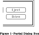 Figure 1–Partial Dialog Box
The disk name displayed in the dialog box is the name of the current disk, initially the disk from which the application was started. The user can click Eject to eject the current disk and insert another, which then becomes the current disk. If there’s an external drive, clicking the Drive button changes the current disk from the one in the external drive to the one in the internal drive or vice versa. The Drive button is inactive whenever there’s only one disk inserted.
Note: Clicking the Drive button actually cycles through all volumes in
drives currently connected to the Macintosh. (Volumes and drives are
discussed in the File Manager chapter.)
If an uninitialized or otherwise unreadable disk is inserted, the Standard File Package calls the Disk Initialization Package to provide the standard user interface for initializing and naming a disk.
Note: The remainder of this section discusses the enhanced Standard File
Package which is only available in the 128K and later ROMs.
The Standard File Package has been modified to work with the hierarchical file system. (This chapter assumes some familiarity with the material presented in the File Manager chapter.) Since a volume’s files are no longer necessarily contained in a single flat directory, the Standard File Package must provide some way for the user to select a file that’s contained in a folder (or subdirectory). It must also provide the user with a way of indicating the directory into which a particular file should be saved.
The dialog box displayed in response to the SFGetFile procedure shows the names of folders (if any) as well as files. Files and folders are distinguished by miniature icons preceding their names. Notice that there are two types of mini-icons for files—one for applications and another for documents. Figure 2 shows the files and folders contained on a sample desktop.
Figure 1–Partial Dialog Box
The disk name displayed in the dialog box is the name of the current disk, initially the disk from which the application was started. The user can click Eject to eject the current disk and insert another, which then becomes the current disk. If there’s an external drive, clicking the Drive button changes the current disk from the one in the external drive to the one in the internal drive or vice versa. The Drive button is inactive whenever there’s only one disk inserted.
Note: Clicking the Drive button actually cycles through all volumes in
drives currently connected to the Macintosh. (Volumes and drives are
discussed in the File Manager chapter.)
If an uninitialized or otherwise unreadable disk is inserted, the Standard File Package calls the Disk Initialization Package to provide the standard user interface for initializing and naming a disk.
Note: The remainder of this section discusses the enhanced Standard File
Package which is only available in the 128K and later ROMs.
The Standard File Package has been modified to work with the hierarchical file system. (This chapter assumes some familiarity with the material presented in the File Manager chapter.) Since a volume’s files are no longer necessarily contained in a single flat directory, the Standard File Package must provide some way for the user to select a file that’s contained in a folder (or subdirectory). It must also provide the user with a way of indicating the directory into which a particular file should be saved.
The dialog box displayed in response to the SFGetFile procedure shows the names of folders (if any) as well as files. Files and folders are distinguished by miniature icons preceding their names. Notice that there are two types of mini-icons for files—one for applications and another for documents. Figure 2 shows the files and folders contained on a sample desktop.
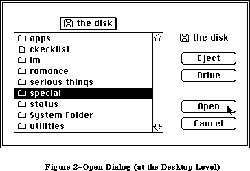 Figure 2–Open Dialog (at the Desktop Level)
To view the files and folders contained in a particular folder, the user must open the folder by clicking it and then clicking the Open button, or by double-clicking on the folder name; this causes the contents of the folder to be displayed. Figure 3 shows the contents of the sample folder special.
Figure 2–Open Dialog (at the Desktop Level)
To view the files and folders contained in a particular folder, the user must open the folder by clicking it and then clicking the Open button, or by double-clicking on the folder name; this causes the contents of the folder to be displayed. Figure 3 shows the contents of the sample folder special.
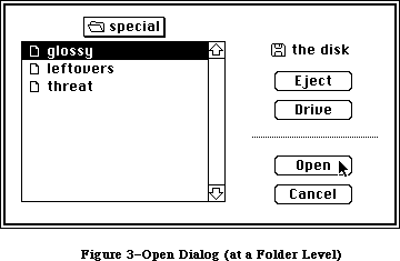 Figure 3–Open Dialog (at a Folder Level)
A current directory button above the list shows the name of the directory whose files and folders are displayed in the list below. If the contents of the desktop (or root directory) are being displayed, the button will show the name of the volume next to either a 3 1/2-inch disk mini-icon or a hard disk mini-icon (as in Figure 2). If the contents of a particular folder (or subdirectory) are being displayed, the button will show the name of that folder next to an open folder mini-icon (as in Figure 3 for instance).
Assembly-language note: The global variable SFSaveDisk always contains the
negative of the volume reference number (never a
working directory reference number) of the volume
to use. If the hierarchical version of the File
Manager is running, the global variable CurDirStore
contains the directory ID of whatever directory
(including the root) was last opened (regardless of
whether a document was actually opened or saved).
With the 64K ROM version of the File Manager,
CurDirStore is not needed and is set to 0.
X-Ref: Technical Note #80
The current directory button provides a way of moving back up through the hierarchical directory structure of a volume. If the user is at the level of a particular folder (or subdirectory), clicking on the button causes a list to pop down. This list gives the path from the current directory back up to the root directory. The rules for displaying and selecting items from this “pop down” list are identical to those for items in a menu. To change levels, select the desired folder and the files and folders at that level will be displayed.
When the user chooses Save As, or Save when the document is untitled, the SFPutFile dialog box contains a list of files and folders similar to the list displayed in response to the Open command. This allows the user to specify the directory into which the file should be placed. A current directory button above the list lets the user move about in the hierarchical structure. File names in the list are dimmed (but displayed, so that the user can see what other files are in the directory). Figure 4 shows an example.
Figure 3–Open Dialog (at a Folder Level)
A current directory button above the list shows the name of the directory whose files and folders are displayed in the list below. If the contents of the desktop (or root directory) are being displayed, the button will show the name of the volume next to either a 3 1/2-inch disk mini-icon or a hard disk mini-icon (as in Figure 2). If the contents of a particular folder (or subdirectory) are being displayed, the button will show the name of that folder next to an open folder mini-icon (as in Figure 3 for instance).
Assembly-language note: The global variable SFSaveDisk always contains the
negative of the volume reference number (never a
working directory reference number) of the volume
to use. If the hierarchical version of the File
Manager is running, the global variable CurDirStore
contains the directory ID of whatever directory
(including the root) was last opened (regardless of
whether a document was actually opened or saved).
With the 64K ROM version of the File Manager,
CurDirStore is not needed and is set to 0.
X-Ref: Technical Note #80
The current directory button provides a way of moving back up through the hierarchical directory structure of a volume. If the user is at the level of a particular folder (or subdirectory), clicking on the button causes a list to pop down. This list gives the path from the current directory back up to the root directory. The rules for displaying and selecting items from this “pop down” list are identical to those for items in a menu. To change levels, select the desired folder and the files and folders at that level will be displayed.
When the user chooses Save As, or Save when the document is untitled, the SFPutFile dialog box contains a list of files and folders similar to the list displayed in response to the Open command. This allows the user to specify the directory into which the file should be placed. A current directory button above the list lets the user move about in the hierarchical structure. File names in the list are dimmed (but displayed, so that the user can see what other files are in the directory). Figure 4 shows an example.
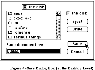 Figure 4–Save Dialog Box (at the Desktop Level)
In both dialog boxes, the Drive, Eject, and Open/Save buttons function as they always have, although their positions have changed. The Save button is always dimmed if the current volume is locked.
Note: No new buttons have been added, so programmers need not worry about
interference with controls they’ve added. The new dialog boxes,
however, are larger than the old boxes; the Standard File Package
does its best to position nonstandard dialogs in a visible and
pleasing position. (Additional details are provided below in the
section “Creating Your Own Dialog Box”.)
When the user dismisses the dialog, whether by Cancel or Save or Open, the directory currently displayed is set to be the working directory (in other words, a call is made to the File Manager function OpenWD).
_______________________________________________________________________________
»USING THE STANDARD FILE PACKAGE
_______________________________________________________________________________
The Standard File Package and the resources it uses are automatically read into memory when one of its routines is called. It in turn reads the Disk Initialization Package into memory if a disk is ejected (in case an uninitialized disk is inserted next); together these packages occupy about 8.5K to 10K bytes, depending on the number of files on the disk.
Call SFPutFile when your application is to save to a file and needs to get the name of the file from the user. Standard applications should do this when the user chooses Save As from the File menu, or Save when the document is untitled. SFPutFile displays a dialog box allowing the user to enter a file name.
Similarly, SFGetFile is useful whenever your application is to open a file and needs to know which one, such as when the user chooses the Open command from a standard application’s File menu. SFGetFile displays a dialog box with a list of file names to choose from.
You pass these routines a reply record, as shown below, and they fill it with information about the user’s reply.
TYPE SFReply = RECORD
good: BOOLEAN; {FALSE if ignore command}
copy: BOOLEAN; {not used}
fType: OSType; {file type or not used}
vRefNum: INTEGER; {volume reference number}
version: INTEGER; {file's version number}
fName: STRING[63] {file name}
END;
The first field of this record determines whether the file operation should take place or the command should be ignored (because the user clicked the Cancel button in the dialog box). The fType field is used by SFGetFile to store the file’s type. The vRefNum, version, and fName fields identify the file chosen by the user; the application passes their values on to the File Manager routine that does the actual file operation. VRefNum contains the volume reference number of the volume containing the file. The version field always contains 0; the use of nonzero version numbers is not supported by this package. For more information on files, volumes, and file operations, see the File Manager chapter.
Assembly-language note: Before calling a Standard File Package routine, if
you set the global variable SFSaveDisk to the negative
of a volume reference number, Standard File will use
that volume and display its name in the dialog box.
(Note that since the volume reference number is
negative, you set SFSaveDisk to a positive value.)
X-Ref: Technical Note #80
Both SFPutFile and SFGetFile allow you to use a nonstandard dialog box; two additional routines, SFPPutFile and SFPGetFile, provide an even more convenient and powerful way of doing this.
Applications that use the Standard File Package properly need no modification to operate on machines equipped with the 128K ROM. The specification of a directory in the SFGetFile and SFPutFile procedures is transparent, due to the fact that working directory reference numbers can always be used in place of volume reference numbers. (The relationship between volume reference numbers and working directory reference numbers is described in detail in the File Manager chapter.) If the user specifies that a given file be opened from or saved to a particular subdirectory, the vRefNum field of the reply record you pass with these routines will be filled with a working directory reference number instead of a volume reference number.
Warning: Programmers who have written their own “standard file” routines or
who rely on SFReply.vRefNum being a volume reference number may
find that their applications are not compatible with the 128K ROM
version of the File Manager.
_______________________________________________________________________________
»Using the Keyboard
The Standard File Package lets you use a variety of keyboard keys to respond to its dialogs. The following special keys (or key sequences) are defined:
Key Sequence Action
Up Arrow Scrolls up (backward) through displayed list
Down Arrow Scrolls down (forward) through displayed list
Command–Up Arrow Closes the current directory
Command–Down Arrow Opens the selected directory
Command–Shift–1 Ejects disk in internal drive
Command–Shift–2 Ejects disk in external drive
Tab Equivalent to Drive button
Return Equivalent to either Open or Save button
Enter Same as Return
Note: The Up Arrow and Down Arrow keys are available on the standard
Macintosh Plus keyboard, and on the optional numeric keypad for
the Macintosh 128K and 512K, as well as on the Macintosh XL keypad.
(See the Macintosh User Interface Guidelines chapter for details on
using the arrow keys.) In addition, with the SFGetFile dialog the
user can type characters to locate files in the list; each time a
character is typed, the list selects and displays the first file
whose initial character matches the typed character.
_______________________________________________________________________________
»STANDARD FILE PACKAGE ROUTINES
_______________________________________________________________________________
Assembly-language note: The trap macro for the Standard File Package is
_Pack3. The routine selectors are as follows:
sfPutFile .EQU 1
sfGetFile .EQU 2
sfPPutFile .EQU 3
sfPGetFile .EQU 4
PROCEDURE SFPutFile (where: Point; prompt: Str255; origName: Str255;
dlgHook: ProcPtr; VAR reply: SFReply);
SFPutFile displays a dialog box allowing the user to specify a file to which data will be written (as during a Save or Save As command). It then repeatedly gets and handles events until the user either confirms the command after entering an appropriate file name or aborts the command by clicking Cancel in the dialog. It reports the user’s reply by filling the fields of the reply record specified by the reply parameter, as described above; the fType field of this record isn’t used.
The general appearance of the standard SFPutFile dialog box is shown in Figure 3. The where parameter specifies the location of the top left corner of the dialog box in global coordinates. The prompt parameter is a line of text to be displayed as a statText item in the dialog box, where shown in Figure 3. The origName parameter contains text that appears as an enabled, selected editText item; for the standard document-saving commands, it should be the current name of the document, or the empty string (to display an insertion point) if the document hasn’t been named yet.
If you want to use the standard SFPutFile dialog box, pass NIL for dlgHook; otherwise, see the information for advanced programmers below.
SFPutFile repeatedly calls the Dialog Manager procedure ModalDialog. When an event involving an enabled dialog item occurs, ModalDialog handles the event and returns the item number, and SFPutFile responds as follows:
• If the Eject or Drive button is clicked, or a disk is inserted,
SFPutFile responds as described above under “About the Standard File
Package”.
• Text entered into the editText item is stored in the fName field of
the reply record. (SFPutFile keeps track of whether there’s currently
any text in the item, and makes the Save button inactive if not.)
• If the Save button is clicked, SFPutFile determines whether the file
name in the fName field of the reply record is appropriate. If so, it
returns control to the application with the first field of the reply
record set to TRUE; otherwise, it responds accordingly, as described
below.
• If the Cancel button in the dialog is clicked, SFPutFile returns control
to the application with the first field of the reply record set to FALSE.
Note: Notice that disk insertion is one of the user actions listed above,
even though ModalDialog normally ignores disk-inserted events. The
reason this works is that SFPutFile calls ModalDialog with a
filterProc function that lets it receive disk-inserted events.
The situations that may cause an entered name to be inappropriate, and SFPutFile’s response to each, are as follows:
• If a file with the specified name already exists on the disk and is
different from what was passed in the origName parameter, the alert
in Figure 5 is displayed. If the user clicks Yes, the file name is
appropriate.
Figure 4–Save Dialog Box (at the Desktop Level)
In both dialog boxes, the Drive, Eject, and Open/Save buttons function as they always have, although their positions have changed. The Save button is always dimmed if the current volume is locked.
Note: No new buttons have been added, so programmers need not worry about
interference with controls they’ve added. The new dialog boxes,
however, are larger than the old boxes; the Standard File Package
does its best to position nonstandard dialogs in a visible and
pleasing position. (Additional details are provided below in the
section “Creating Your Own Dialog Box”.)
When the user dismisses the dialog, whether by Cancel or Save or Open, the directory currently displayed is set to be the working directory (in other words, a call is made to the File Manager function OpenWD).
_______________________________________________________________________________
»USING THE STANDARD FILE PACKAGE
_______________________________________________________________________________
The Standard File Package and the resources it uses are automatically read into memory when one of its routines is called. It in turn reads the Disk Initialization Package into memory if a disk is ejected (in case an uninitialized disk is inserted next); together these packages occupy about 8.5K to 10K bytes, depending on the number of files on the disk.
Call SFPutFile when your application is to save to a file and needs to get the name of the file from the user. Standard applications should do this when the user chooses Save As from the File menu, or Save when the document is untitled. SFPutFile displays a dialog box allowing the user to enter a file name.
Similarly, SFGetFile is useful whenever your application is to open a file and needs to know which one, such as when the user chooses the Open command from a standard application’s File menu. SFGetFile displays a dialog box with a list of file names to choose from.
You pass these routines a reply record, as shown below, and they fill it with information about the user’s reply.
TYPE SFReply = RECORD
good: BOOLEAN; {FALSE if ignore command}
copy: BOOLEAN; {not used}
fType: OSType; {file type or not used}
vRefNum: INTEGER; {volume reference number}
version: INTEGER; {file's version number}
fName: STRING[63] {file name}
END;
The first field of this record determines whether the file operation should take place or the command should be ignored (because the user clicked the Cancel button in the dialog box). The fType field is used by SFGetFile to store the file’s type. The vRefNum, version, and fName fields identify the file chosen by the user; the application passes their values on to the File Manager routine that does the actual file operation. VRefNum contains the volume reference number of the volume containing the file. The version field always contains 0; the use of nonzero version numbers is not supported by this package. For more information on files, volumes, and file operations, see the File Manager chapter.
Assembly-language note: Before calling a Standard File Package routine, if
you set the global variable SFSaveDisk to the negative
of a volume reference number, Standard File will use
that volume and display its name in the dialog box.
(Note that since the volume reference number is
negative, you set SFSaveDisk to a positive value.)
X-Ref: Technical Note #80
Both SFPutFile and SFGetFile allow you to use a nonstandard dialog box; two additional routines, SFPPutFile and SFPGetFile, provide an even more convenient and powerful way of doing this.
Applications that use the Standard File Package properly need no modification to operate on machines equipped with the 128K ROM. The specification of a directory in the SFGetFile and SFPutFile procedures is transparent, due to the fact that working directory reference numbers can always be used in place of volume reference numbers. (The relationship between volume reference numbers and working directory reference numbers is described in detail in the File Manager chapter.) If the user specifies that a given file be opened from or saved to a particular subdirectory, the vRefNum field of the reply record you pass with these routines will be filled with a working directory reference number instead of a volume reference number.
Warning: Programmers who have written their own “standard file” routines or
who rely on SFReply.vRefNum being a volume reference number may
find that their applications are not compatible with the 128K ROM
version of the File Manager.
_______________________________________________________________________________
»Using the Keyboard
The Standard File Package lets you use a variety of keyboard keys to respond to its dialogs. The following special keys (or key sequences) are defined:
Key Sequence Action
Up Arrow Scrolls up (backward) through displayed list
Down Arrow Scrolls down (forward) through displayed list
Command–Up Arrow Closes the current directory
Command–Down Arrow Opens the selected directory
Command–Shift–1 Ejects disk in internal drive
Command–Shift–2 Ejects disk in external drive
Tab Equivalent to Drive button
Return Equivalent to either Open or Save button
Enter Same as Return
Note: The Up Arrow and Down Arrow keys are available on the standard
Macintosh Plus keyboard, and on the optional numeric keypad for
the Macintosh 128K and 512K, as well as on the Macintosh XL keypad.
(See the Macintosh User Interface Guidelines chapter for details on
using the arrow keys.) In addition, with the SFGetFile dialog the
user can type characters to locate files in the list; each time a
character is typed, the list selects and displays the first file
whose initial character matches the typed character.
_______________________________________________________________________________
»STANDARD FILE PACKAGE ROUTINES
_______________________________________________________________________________
Assembly-language note: The trap macro for the Standard File Package is
_Pack3. The routine selectors are as follows:
sfPutFile .EQU 1
sfGetFile .EQU 2
sfPPutFile .EQU 3
sfPGetFile .EQU 4
PROCEDURE SFPutFile (where: Point; prompt: Str255; origName: Str255;
dlgHook: ProcPtr; VAR reply: SFReply);
SFPutFile displays a dialog box allowing the user to specify a file to which data will be written (as during a Save or Save As command). It then repeatedly gets and handles events until the user either confirms the command after entering an appropriate file name or aborts the command by clicking Cancel in the dialog. It reports the user’s reply by filling the fields of the reply record specified by the reply parameter, as described above; the fType field of this record isn’t used.
The general appearance of the standard SFPutFile dialog box is shown in Figure 3. The where parameter specifies the location of the top left corner of the dialog box in global coordinates. The prompt parameter is a line of text to be displayed as a statText item in the dialog box, where shown in Figure 3. The origName parameter contains text that appears as an enabled, selected editText item; for the standard document-saving commands, it should be the current name of the document, or the empty string (to display an insertion point) if the document hasn’t been named yet.
If you want to use the standard SFPutFile dialog box, pass NIL for dlgHook; otherwise, see the information for advanced programmers below.
SFPutFile repeatedly calls the Dialog Manager procedure ModalDialog. When an event involving an enabled dialog item occurs, ModalDialog handles the event and returns the item number, and SFPutFile responds as follows:
• If the Eject or Drive button is clicked, or a disk is inserted,
SFPutFile responds as described above under “About the Standard File
Package”.
• Text entered into the editText item is stored in the fName field of
the reply record. (SFPutFile keeps track of whether there’s currently
any text in the item, and makes the Save button inactive if not.)
• If the Save button is clicked, SFPutFile determines whether the file
name in the fName field of the reply record is appropriate. If so, it
returns control to the application with the first field of the reply
record set to TRUE; otherwise, it responds accordingly, as described
below.
• If the Cancel button in the dialog is clicked, SFPutFile returns control
to the application with the first field of the reply record set to FALSE.
Note: Notice that disk insertion is one of the user actions listed above,
even though ModalDialog normally ignores disk-inserted events. The
reason this works is that SFPutFile calls ModalDialog with a
filterProc function that lets it receive disk-inserted events.
The situations that may cause an entered name to be inappropriate, and SFPutFile’s response to each, are as follows:
• If a file with the specified name already exists on the disk and is
different from what was passed in the origName parameter, the alert
in Figure 5 is displayed. If the user clicks Yes, the file name is
appropriate.
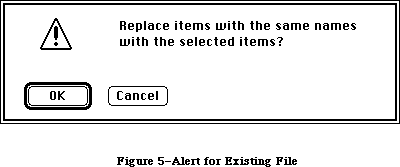 Figure 5–Alert for Existing File
• If the disk to which the file should be written is locked, the alert
in Figure 6 is displayed. If a system error occurs, a similar alert
is displayed, with the message “A system error occurred; please try
again” (this is unrelated to the fatal system errors reported by the
System Error Handler).
Figure 5–Alert for Existing File
• If the disk to which the file should be written is locked, the alert
in Figure 6 is displayed. If a system error occurs, a similar alert
is displayed, with the message “A system error occurred; please try
again” (this is unrelated to the fatal system errors reported by the
System Error Handler).
 Figure 6–Alert for Locked Disk
Note: The user may specify a disk name (preceding the file name and
separated from it by a colon). If the disk isn’t currently in a
drive, an alert similar to the one in Figure 6 is displayed.
The ability to specify a disk name is supported for historical
reasons only; users should not be encouraged to do it.
After the user clicks No or Cancel in response to one of these alerts, SFPutFile dismisses the alert box and continues handling events (so a different name may be entered).
Advanced programmers: You can create your own dialog box rather than use the
standard SFPutFile dialog. However, future compatibility
is not guaranteed if you don’t use the standard
SFPutFile dialog. To create a nonstandard dialog, you
must provide your own dialog template and store it in
your application’s resource file with the same resource
ID that the standard template has in the system resource
file:
CONST putDlgID = -3999; {SFPutFile dialog template ID}
X-Ref: Technical Note #47
Note: The SFPPutFile procedure, described below, lets you use any resource
ID for your nonstandard dialog box.
Your dialog template must specify that the dialog window be invisible, and your dialog must contain all the standard items, as listed below. The appearance and location of these items in your dialog may be different. You can make an item
“invisible” by giving it a display rectangle that’s off the screen. The display rectangle for each item in the standard dialog box is given below. The rectangle for the standard dialog box itself is (0,0)(304,104).
Item number Item Standard display rectangle
1 Save button (12,74)(82,92)
2 Cancel button (114,74)(184,92)
3 Prompt string (statText) (12,12)(184,28)
4 UserItem for disk name (209,16)(295,34)
5 Eject button (217,43)(287,61)
6 Drive button (217,74)(287,92)
7 EditText item for file name (14,34)(182,50)
8 UserItem for dotted line (200,16)(201,88)
Note: Remember that the display rectangle for any “invisible” text item must
be at least about 20 pixels wide.
If your dialog has additional items beyond the standard ones, or if you want to handle any of the standard items in a nonstandard manner, you must write your own dlgHook function and point to it with dlgHook. Your dlgHook function should have two parameters and return an integer value. For example, this is how it would be declared if it were named MyDlg:
FUNCTION MyDlg (item: INTEGER; theDialog: DialogPtr) : INTEGER;
Immediately after calling ModalDialog, SFPutFile calls your dlgHook function, passing it the item number returned by ModalDialog and a pointer to the dialog record describing your dialog box. Using these two parameters, your dlgHook function should determine how to handle the event. There are predefined constants for the item numbers of standard enabled items, as follows:
CONST putSave = 1; {Save button}
putCancel = 2; {Cancel button}
putEject = 5; {Eject button}
putDrive = 6; {Drive button}
putName = 7; {editText item for file name}
After handling the event (or, perhaps, after ignoring it) the dlgHook function must return an item number to SFPutFile. If the item number is one of those listed above, SFPutFile responds in the standard way; otherwise, it does nothing.
Note: For advanced programmers who want to change the appearance of the
alerts displayed when an inappropriate file name is entered, the
resource IDs of those alerts in the system resource file are listed
below.
Alert Resource ID
Disk not found –3994
System error –3995
Existing file –3996
Locked disk –3997
PROCEDURE SFPPutFile (where: Point; prompt: Str255; origName: Str255;
dlgHook: ProcPtr; VAR reply: SFReply; dlgID: INTEGER;
filterProc: ProcPtr);
SFPPutFile is an alternative to SFPutFile for advanced programmers who want to use a nonstandard dialog box. It’s the same as SFPutFile except for the two additional parameters dlgID and filterProc.
DlgID is the resource ID of the dialog template to be used instead of the standard one (so you can use whatever ID you wish rather than the same one as the standard).
The filterProc parameter determines how ModalDialog will filter events when called by SFPPutFile. If filterProc is NIL, ModalDialog does the standard filtering that it does when called by SFPutFile; otherwise, filterProc should point to a function for ModalDialog to execute after doing the standard filtering. The function must be the same as one you would pass directly to ModalDialog in its filterProc parameter. (See the Dialog Manager chapter for more information.)
PROCEDURE SFGetFile (where: Point; prompt: Str255; fileFilter: ProcPtr;
numTypes: INTEGER; typeList: SFTypeList;
dlgHook: ProcPtr; VAR reply: SFReply);
SFGetFile displays a dialog box listing the names of a specific group of files from which the user can select one to be opened (as during an Open command). It then repeatedly gets and handles events until the user either confirms the command after choosing a file name or aborts the command by clicking Cancel in the dialog. It reports the user’s reply by filling the fields of the reply record specified by the reply parameter, as described above under “Using the Standard File Package”.
The general appearance of the standard SFGetFile dialog box is shown in Figure 1. File names are sorted in order of the ASCII codes of their characters, ignoring diacritical marks and mapping lowercase characters to their uppercase equivalents. If there are more file names than can be displayed at one time, the scroll bar is active; otherwise, the scroll bar is inactive.
The where parameter specifies the location of the top left corner of the dialog box in global coordinates. The prompt parameter is ignored; it’s there for historical purposes only.
The fileFilter, numTypes, and typeList parameters determine which files appear in the dialog box. SFGetFile first looks at numTypes and typeList to determine what types of files to display, then it executes the function pointed to by fileFilter (if any) to do additional filtering on which files to display. File types are discussed in the Finder Interface chapter. For example, if the application is concerned only with pictures, you won’t want to display the names of any text files.
Pass –1 for numTypes to display all types of files; otherwise, pass the number of file types (up to 4) that you want to display, and pass the types themselves in typeList. The SFTypeList data type is defined as follows:
TYPE SFTypeList = ARRAY[0..3] OF OSType;
Assembly-language note: If you need to specify more than four types, pass a
pointer to an array with the desired number of entries.
If fileFilter isn’t NIL, SFGetFile executes the function it points to for each file, to determine whether the file should be displayed. The fileFilter function has one parameter and returns a Boolean value. For example:
FUNCTION MyFileFilter (paramBlock: ParmBlkPtr) : BOOLEAN;
SFGetFile passes this function the file information it gets by calling the File Manager procedure GetFileInfo (see the File Manager chapter for details). The function selects which files should appear in the dialog by returning FALSE for every file that should be shown and TRUE for every file that shouldn’t be shown.
Note: As described in the File Manager chapter, a flag can be set that tells
the Finder not to display a particular file’s icon on the desktop;
this has no effect on whether SFGetFile will list the file name.
If you want to use the standard SFGetFile dialog box, pass NIL for dlgHook; otherwise, see the information for advanced programmers below.
Like SFPutFile, SFGetFile repeatedly calls the Dialog Manager procedure ModalDialog. When an event involving an enabled dialog item occurs, ModalDialog handles the event and returns the item number, and SFGetFile responds as follows:
• If the Eject or Drive button is clicked, or a disk is inserted,
SFGetFile responds as described above under “About the Standard File
Package”.
• If clicking or dragging occurs in the scroll bar, the contents of the
dialog box are redrawn accordingly.
• If a file name is clicked, it’s selected and stored in the fName field
of the reply record. (SFGetFile keeps track of whether a file name is
currently selected, and makes the Open button inactive if not.)
• If the Open button is clicked, SFGetFile returns control to the
application with the first field of the reply record set to TRUE.
• If a file name is double-clicked, SFGetFile responds as if the user
clicked the file name and then the Open button.
• If the Cancel button in the dialog is clicked, SFGetFile returns control
to the application with the first field of the reply record set to FALSE.
If a character key is pressed, SFGetFile selects the first file name starting with the character typed, scrolling the list of names if necessary to show the selection. If no file name starts with the character, SFGetFile selects the first file name starting with a character whose ASCII code is greater than the character typed.
Advanced programmers: You can create your own dialog box rather than use the
standard SFGetFile dialog. However, future compatibility
is not guaranteed if you don’t use the standard
SFGetFile dialog. To create a nonstandard dialog, you
must provide your own dialog template and store it in
your application’s resource file with the same resource
ID that the standard template has in the system resource
file:
CONST getDlgID = -4000; {SFGetFile dialog template ID}
Note: The SFPGetFile procedure, described below, lets you use any resource
ID for your nonstandard dialog box.
Your dialog template must specify that the dialog window be invisible, and your dialog must contain all the standard items, as listed below. The appearance and location of these items in your dialog may be different. You can make an item
“invisible” by giving it a display rectangle that’s off the screen. The display rectangle for each item in the standard dialog box is given below. The rectangle for the standard dialog box itself is (0,0)(348,136).
Item number Item Standard display rectangle
1 Open button (152,28)(232,46)
2 Invisible button (1152,59)(1232,77)
3 Cancel button (152,90)(232,108)
4 UserItem for disk name (248,28)(344,46)
5 Eject button (256,59)(336,77)
6 Drive button (256,90)(336,108)
7 UserItem for file name list (12,11)(125,125)
8 UserItem for scroll bar (124,11)(140,125)
9 UserItem for dotted line (244,20)(245,116)
10 Invisible text (statText) (1044,20)(1145,116)
If your dialog has additional items beyond the standard ones, or if you want to handle any of the standard items in a nonstandard manner, you must write your own dlgHook function and point to it with dlgHook. Your dlgHook function should have two parameters and return an integer value. For example, this is how it would be declared if it were named MyDlg:
FUNCTION MyDlg (item: INTEGER; theDialog: DialogPtr) : INTEGER;
Immediately after calling ModalDialog, SFGetFile calls your dlgHook function, passing it the item number returned by ModalDialog and a pointer to the dialog record describing your dialog box. Using these two parameters, your dlgHook function should determine how to handle the event. There are predefined constants for the item numbers of standard enabled items, as follows:
CONST getOpen = 1; {Open button}
getCancel = 3; {Cancel button}
getEject = 5; {Eject button}
getDrive = 6; {Drive button}
getNmList = 7; {userItem for file name list}
getScroll = 8; {userItem for scroll bar}
ModalDialog also returns “fake” item numbers in the following situations, which are detected by its filterProc function:
• When it receives a null event, it returns 100. Note that since it calls
GetNextEvent with a mask that excludes disk-inserted events, ModalDialog
sees them as null events, too.
• When a key-down event occurs, it returns 1000 plus the ASCII code of the
character.
After handling the event (or, perhaps, after ignoring it) your dlgHook function must return an item number to SFGetFile. If the item number is one of those listed above, SFGetFile responds in the standard way; otherwise, it does nothing.
PROCEDURE SFPGetFile (where: Point; prompt: Str255; fileFilter: ProcPtr;
numTypes: INTEGER; typeList: SFTypeList;
dlgHook: ProcPtr; VAR reply: SFReply; dlgID: INTEGER;
filterProc: ProcPtr);
SFPGetFile is an alternative to SFGetFile for advanced programmers who want to use a nonstandard dialog box. It’s the same as SFGetFile except for the two additional parameters dlgID and filterProc.
DlgID is the resource ID of the dialog template to be used instead of the standard one (so you can use whatever ID you wish rather than the same one as the standard).
The filterProc parameter determines how ModalDialog will filter events when called by SFPGetFile. If filterProc is NIL, ModalDialog does the standard filtering that it does when called by SFGetFile; otherwise, filterProc should point to a function for ModalDialog to execute after doing the standard filtering. The function must be the same as one you would pass directly to ModalDialog in its filterProc parameter. (See the Dialog Manager chapter for more information.) Note that the standard filtering will detect key-down events only if the dialog template ID is the standard one.
_______________________________________________________________________________
»CREATING YOUR OWN DIALOG BOX
_______________________________________________________________________________
This section is for advanced programmers who want to create their own dialog boxes rather than use the standard SFPutFile and SFGetFile dialogs.
Note: This section discusses the enhanced Standard File Package
which is only available in the 128K and later ROMs.
Warning: Future compatibility is not guaranteed if you don’t use the standard
dialogs.
X-Ref: Technical Note #47
The addition of the file name list to the SFPutFile dialog, as well as the addition of current directory buttons to both SFPutFile and SFGetFile, requires that the dialog boxes for each call be made larger and the items in the box moved down. Although new dialog templates and item lists are provided, the Standard File Package also needs an algorithm for transforming old or nonstandard dialog templates and item lists.
To maintain compatibility with existing applications, the Standard File Package uses only the existing dialog items. In SFPutFile, a userItem for the new file name list replaces the dotted line in item number 8. In SFGetFile, the scroll bar userItem in item number 8 is no longer used. For both SFPutFile and SFGetFile, the information for the current directory button and the scroll bars is maintained internally.
The Standard File Package determines if a dialog needs to be transformed by looking at the width of item number 8 (the dotted line or scroll bar) as specified in the item’s rectangle. If the width of item number 8 specifies either a dotted line (a width of 1) or a scroll bar (a width of 16), the dialog will be transformed.
Note: If a dialog needs to be transformed, the box is enlarged to make room
for both the scrolling list and the current directory button. All of
the items are moved down to their original position relative to the
bottom of the box, and the scrolling list and current directory button
are added. The dialog is then centered on the screen. If it overlaps
the menu bar, it’s moved down. If it extends below or to the right of
the screen, it’s repositioned to make the entire dialog visible. In the
case of certain unusual dialogs, the bottom of the dialog may not be
visible.
To create nonstandard dialogs that will not be transformed (in other words, ones in which you leave room for the list and current directory button), simply set item number 8 to the desired size and location of your file name list, including scroll bars (for SFPutFile), and set item number 8 to have a width other than 16 (for SFGetFile). The scroll bar is placed within the specified file name list’s rectangle.
_______________________________________________________________________________
»The DlgHook Function
In the old Standard File Package, a dlgHook routine could not accurately monitor what file was being opened, since it could not detect a double-click. In the new Standard File Package, double-clicks on files are interpreted as clicks on the Open button (item number 1), allowing the dlgHook to intercept files to be opened. With folders, however, both clicks on the Open button and double-clicks are passed to the hook as “fake” item number 103.
A new fake item number 102 is generated by a click in the current directory button; it causes the file list to be pulled down and tracked.
To redisplay the file list in GetFile (which you might do if your dialog box contains radio buttons that let you choose different file types to be
displayed), change item number 100 (a null event) into item number 101 (which means redisplay the list) from within the dialog hook.
Note: Disk-inserted events are handled internally; they are not (and never
have been) returned as “fake” item number 100. Item number 100 is
returned only when no event has taken place.
Before the dlgHook routine is called, information for the selected file or folder is stuffed in the reply record (which can be examined on null events). If no file or folder is selected, fName and fType are both NIL. If a file is selected, fName will not be NIL and will contain the file name. If a folder is selected, fType will not be NIL and will contain the dirID. This is done before the dialog hook is called, regardless of which event is being returned.
Three of the new Standard File Package alerts display an OK button instead of a Cancel button:
Alert Resource ID
Disk not found –3994
System error –3995
Locked disk –3997
Also, the text of the alert number –3994 (previously “Can’t find that disk.”) has been changed to “Bad character in name, or can’t find that disk.” This reflects the fact that this alert is generated if there’s a colon in the name.
With nonhierarchical volumes, SFGetFile passes the fileFilter function the file information it gets by calling the File Manager function GetFileInfo. With hierarchical volumes, it gets this information from the GetCatInfo function. SFPutFile does not support a fileFilter function.
_______________________________________________________________________________
»SUMMARY OF THE STANDARD FILE PACKAGE
_______________________________________________________________________________
Constants
CONST
{ SFPutFile dialog template ID }
putDlgID = -3999;
{ Item numbers of enabled items in SFPutFile dialog }
putSave = 1; {Save button}
putCancel = 2; {Cancel button}
putEject = 5; {Eject button}
putDrive = 6; {Drive button}
putName = 7; {editText item for file name}
{ SFGetFile dialog template ID }
getDlgID = -4000;
{ Item numbers of enabled items in SFGetFile dialog }
getOpen = 1; {Open button}
getCancel = 3; {Cancel button}
getEject = 5; {Eject button}
getDrive = 6; {Drive button}
getNmList = 7; {userItem for file name list}
getScroll = 8; {userItem for scroll bar}
_______________________________________________________________________________
Data Types
TYPE
SFReply = RECORD
good: BOOLEAN; {FALSE if ignore command}
copy: BOOLEAN; {not used}
fType: OSType; {file type or not used}
vRefNum: INTEGER; {volume reference number}
version: INTEGER; {file's version number}
fName: STRING[63] {file name}
END;
SFTypeList = ARRAY[0..3] OF OSType;
_______________________________________________________________________________
Routines
PROCEDURE SFPutFile (where: Point; prompt: Str255; origName: Str255;
dlgHook: ProcPtr; VAR reply: SFReply);
PROCEDURE SFPPutFile (where: Point; prompt: Str255; origName: Str255;
dlgHook: ProcPtr; VAR reply: SFReply; dlgID: INTEGER;
filterProc: ProcPtr);
PROCEDURE SFGetFile (where: Point; prompt: Str255; fileFilter: ProcPtr;
numTypes: INTEGER; typeList: SFTypeList;
dlgHook: ProcPtr; VAR reply: SFReply);
PROCEDURE SFPGetFile (where: Point; prompt: Str255; fileFilter: ProcPtr;
numTypes: INTEGER; typeList: SFTypeList;
dlgHook: ProcPtr; VAR reply: SFReply; dlgID: INTEGER;
filterProc: ProcPtr);
_______________________________________________________________________________
DlgHook Function
FUNCTION MyDlg (item: INTEGER; theDialog: DialogPtr) : INTEGER;
_______________________________________________________________________________
FileFilter Function
FUNCTION MyFileFilter (paramBlock: ParmBlkPtr) : BOOLEAN;
_______________________________________________________________________________
Standard SFPutFile Items
Item number Item Standard display rectangle
1 Save button (12,74)(82,92)
2 Cancel button (114,74)(184,92)
3 Prompt string (statText) (12,12)(184,28)
4 UserItem for disk name (209,16)(295,34)
5 Eject button (217,43)(287,61)
6 Drive button (217,74)(287,92)
7 EditText item for file name (14,34)(182,50)
8 UserItem for dotted line (200,16)(201,88)
_______________________________________________________________________________
Resource IDs of SFPutFile Alerts
Alert Resource ID
Disk not found –3994
System error –3995
Existing file –3996
Locked disk –3997
_______________________________________________________________________________
Standard SFGetFile Items
Item number Item Standard display rectangle
1 Open button (152,28)(232,46)
2 Invisible button (1152,59)(1232,77)
3 Cancel button (152,90)(232,108)
4 UserItem for disk name (248,28)(344,46)
5 Eject button (256,59)(336,77)
6 Drive button (256,90)(336,108)
7 UserItem for file name list (12,11)(125,125)
8 UserItem for scroll bar (124,11)(140,125)
9 UserItem for dotted line (244,20)(245,116)
10 Invisible text (statText) (1044,20)(1145,116)
_______________________________________________________________________________
Assembly-Language Information
Constants
; SFPutFile dialog template ID
putDlgID .EQU -3999
; Item numbers of enabled items in SFPutFile dialog
putSave .EQU 1 ;Save button
putCancel .EQU 2 ;Cancel button
putEject .EQU 5 ;Eject button
putDrive .EQU 6 ;Drive button
putName .EQU 7 ;editText item for file name
; SFGetFile dialog template ID
getDlgID .EQU -4000
; Item numbers of enabled items in SFGetFile dialog
getOpen .EQU 1 ;Open button
getCancel .EQU 3 ;Cancel button
getEject .EQU 5 ;Eject button
getDrive .EQU 6 ;Drive button
getNmList .EQU 7 ;userItem for file name list
getScroll .EQU 8 ;userItem for scroll bar
; Routine selectors
sfPutFile .EQU 1
sfGetFile .EQU 2
sfPPutFile .EQU 3
sfPGetFile .EQU 4
Reply Record Data Structure
rGood 0 if ignore command (byte)
rType File type (long)
rVolume Volume reference number (word)
rVersion File’s version number (word)
rName File name (length byte followed by up to 63 characters)
Trap Macro Name
_Pack3
Variables
SFSaveDisk Negative of volume reference number used by
Standard File Package (word)
CurDirStore Directory ID of directory last opened (long)
SFSaveDisk Negative of volume reference number (word)
Further Reference:
_______________________________________________________________________________
QuickDraw
Toolbox Event Manager
Dialog Manager
Package Manager
Technical Note #47, Customizing Standard File
Technical Note #80, Standard File Tips
Technical Note #99, Standard File Bug in System 3.2
Technical Note #246, Mixing HFS and C File I/O
Figure 6–Alert for Locked Disk
Note: The user may specify a disk name (preceding the file name and
separated from it by a colon). If the disk isn’t currently in a
drive, an alert similar to the one in Figure 6 is displayed.
The ability to specify a disk name is supported for historical
reasons only; users should not be encouraged to do it.
After the user clicks No or Cancel in response to one of these alerts, SFPutFile dismisses the alert box and continues handling events (so a different name may be entered).
Advanced programmers: You can create your own dialog box rather than use the
standard SFPutFile dialog. However, future compatibility
is not guaranteed if you don’t use the standard
SFPutFile dialog. To create a nonstandard dialog, you
must provide your own dialog template and store it in
your application’s resource file with the same resource
ID that the standard template has in the system resource
file:
CONST putDlgID = -3999; {SFPutFile dialog template ID}
X-Ref: Technical Note #47
Note: The SFPPutFile procedure, described below, lets you use any resource
ID for your nonstandard dialog box.
Your dialog template must specify that the dialog window be invisible, and your dialog must contain all the standard items, as listed below. The appearance and location of these items in your dialog may be different. You can make an item
“invisible” by giving it a display rectangle that’s off the screen. The display rectangle for each item in the standard dialog box is given below. The rectangle for the standard dialog box itself is (0,0)(304,104).
Item number Item Standard display rectangle
1 Save button (12,74)(82,92)
2 Cancel button (114,74)(184,92)
3 Prompt string (statText) (12,12)(184,28)
4 UserItem for disk name (209,16)(295,34)
5 Eject button (217,43)(287,61)
6 Drive button (217,74)(287,92)
7 EditText item for file name (14,34)(182,50)
8 UserItem for dotted line (200,16)(201,88)
Note: Remember that the display rectangle for any “invisible” text item must
be at least about 20 pixels wide.
If your dialog has additional items beyond the standard ones, or if you want to handle any of the standard items in a nonstandard manner, you must write your own dlgHook function and point to it with dlgHook. Your dlgHook function should have two parameters and return an integer value. For example, this is how it would be declared if it were named MyDlg:
FUNCTION MyDlg (item: INTEGER; theDialog: DialogPtr) : INTEGER;
Immediately after calling ModalDialog, SFPutFile calls your dlgHook function, passing it the item number returned by ModalDialog and a pointer to the dialog record describing your dialog box. Using these two parameters, your dlgHook function should determine how to handle the event. There are predefined constants for the item numbers of standard enabled items, as follows:
CONST putSave = 1; {Save button}
putCancel = 2; {Cancel button}
putEject = 5; {Eject button}
putDrive = 6; {Drive button}
putName = 7; {editText item for file name}
After handling the event (or, perhaps, after ignoring it) the dlgHook function must return an item number to SFPutFile. If the item number is one of those listed above, SFPutFile responds in the standard way; otherwise, it does nothing.
Note: For advanced programmers who want to change the appearance of the
alerts displayed when an inappropriate file name is entered, the
resource IDs of those alerts in the system resource file are listed
below.
Alert Resource ID
Disk not found –3994
System error –3995
Existing file –3996
Locked disk –3997
PROCEDURE SFPPutFile (where: Point; prompt: Str255; origName: Str255;
dlgHook: ProcPtr; VAR reply: SFReply; dlgID: INTEGER;
filterProc: ProcPtr);
SFPPutFile is an alternative to SFPutFile for advanced programmers who want to use a nonstandard dialog box. It’s the same as SFPutFile except for the two additional parameters dlgID and filterProc.
DlgID is the resource ID of the dialog template to be used instead of the standard one (so you can use whatever ID you wish rather than the same one as the standard).
The filterProc parameter determines how ModalDialog will filter events when called by SFPPutFile. If filterProc is NIL, ModalDialog does the standard filtering that it does when called by SFPutFile; otherwise, filterProc should point to a function for ModalDialog to execute after doing the standard filtering. The function must be the same as one you would pass directly to ModalDialog in its filterProc parameter. (See the Dialog Manager chapter for more information.)
PROCEDURE SFGetFile (where: Point; prompt: Str255; fileFilter: ProcPtr;
numTypes: INTEGER; typeList: SFTypeList;
dlgHook: ProcPtr; VAR reply: SFReply);
SFGetFile displays a dialog box listing the names of a specific group of files from which the user can select one to be opened (as during an Open command). It then repeatedly gets and handles events until the user either confirms the command after choosing a file name or aborts the command by clicking Cancel in the dialog. It reports the user’s reply by filling the fields of the reply record specified by the reply parameter, as described above under “Using the Standard File Package”.
The general appearance of the standard SFGetFile dialog box is shown in Figure 1. File names are sorted in order of the ASCII codes of their characters, ignoring diacritical marks and mapping lowercase characters to their uppercase equivalents. If there are more file names than can be displayed at one time, the scroll bar is active; otherwise, the scroll bar is inactive.
The where parameter specifies the location of the top left corner of the dialog box in global coordinates. The prompt parameter is ignored; it’s there for historical purposes only.
The fileFilter, numTypes, and typeList parameters determine which files appear in the dialog box. SFGetFile first looks at numTypes and typeList to determine what types of files to display, then it executes the function pointed to by fileFilter (if any) to do additional filtering on which files to display. File types are discussed in the Finder Interface chapter. For example, if the application is concerned only with pictures, you won’t want to display the names of any text files.
Pass –1 for numTypes to display all types of files; otherwise, pass the number of file types (up to 4) that you want to display, and pass the types themselves in typeList. The SFTypeList data type is defined as follows:
TYPE SFTypeList = ARRAY[0..3] OF OSType;
Assembly-language note: If you need to specify more than four types, pass a
pointer to an array with the desired number of entries.
If fileFilter isn’t NIL, SFGetFile executes the function it points to for each file, to determine whether the file should be displayed. The fileFilter function has one parameter and returns a Boolean value. For example:
FUNCTION MyFileFilter (paramBlock: ParmBlkPtr) : BOOLEAN;
SFGetFile passes this function the file information it gets by calling the File Manager procedure GetFileInfo (see the File Manager chapter for details). The function selects which files should appear in the dialog by returning FALSE for every file that should be shown and TRUE for every file that shouldn’t be shown.
Note: As described in the File Manager chapter, a flag can be set that tells
the Finder not to display a particular file’s icon on the desktop;
this has no effect on whether SFGetFile will list the file name.
If you want to use the standard SFGetFile dialog box, pass NIL for dlgHook; otherwise, see the information for advanced programmers below.
Like SFPutFile, SFGetFile repeatedly calls the Dialog Manager procedure ModalDialog. When an event involving an enabled dialog item occurs, ModalDialog handles the event and returns the item number, and SFGetFile responds as follows:
• If the Eject or Drive button is clicked, or a disk is inserted,
SFGetFile responds as described above under “About the Standard File
Package”.
• If clicking or dragging occurs in the scroll bar, the contents of the
dialog box are redrawn accordingly.
• If a file name is clicked, it’s selected and stored in the fName field
of the reply record. (SFGetFile keeps track of whether a file name is
currently selected, and makes the Open button inactive if not.)
• If the Open button is clicked, SFGetFile returns control to the
application with the first field of the reply record set to TRUE.
• If a file name is double-clicked, SFGetFile responds as if the user
clicked the file name and then the Open button.
• If the Cancel button in the dialog is clicked, SFGetFile returns control
to the application with the first field of the reply record set to FALSE.
If a character key is pressed, SFGetFile selects the first file name starting with the character typed, scrolling the list of names if necessary to show the selection. If no file name starts with the character, SFGetFile selects the first file name starting with a character whose ASCII code is greater than the character typed.
Advanced programmers: You can create your own dialog box rather than use the
standard SFGetFile dialog. However, future compatibility
is not guaranteed if you don’t use the standard
SFGetFile dialog. To create a nonstandard dialog, you
must provide your own dialog template and store it in
your application’s resource file with the same resource
ID that the standard template has in the system resource
file:
CONST getDlgID = -4000; {SFGetFile dialog template ID}
Note: The SFPGetFile procedure, described below, lets you use any resource
ID for your nonstandard dialog box.
Your dialog template must specify that the dialog window be invisible, and your dialog must contain all the standard items, as listed below. The appearance and location of these items in your dialog may be different. You can make an item
“invisible” by giving it a display rectangle that’s off the screen. The display rectangle for each item in the standard dialog box is given below. The rectangle for the standard dialog box itself is (0,0)(348,136).
Item number Item Standard display rectangle
1 Open button (152,28)(232,46)
2 Invisible button (1152,59)(1232,77)
3 Cancel button (152,90)(232,108)
4 UserItem for disk name (248,28)(344,46)
5 Eject button (256,59)(336,77)
6 Drive button (256,90)(336,108)
7 UserItem for file name list (12,11)(125,125)
8 UserItem for scroll bar (124,11)(140,125)
9 UserItem for dotted line (244,20)(245,116)
10 Invisible text (statText) (1044,20)(1145,116)
If your dialog has additional items beyond the standard ones, or if you want to handle any of the standard items in a nonstandard manner, you must write your own dlgHook function and point to it with dlgHook. Your dlgHook function should have two parameters and return an integer value. For example, this is how it would be declared if it were named MyDlg:
FUNCTION MyDlg (item: INTEGER; theDialog: DialogPtr) : INTEGER;
Immediately after calling ModalDialog, SFGetFile calls your dlgHook function, passing it the item number returned by ModalDialog and a pointer to the dialog record describing your dialog box. Using these two parameters, your dlgHook function should determine how to handle the event. There are predefined constants for the item numbers of standard enabled items, as follows:
CONST getOpen = 1; {Open button}
getCancel = 3; {Cancel button}
getEject = 5; {Eject button}
getDrive = 6; {Drive button}
getNmList = 7; {userItem for file name list}
getScroll = 8; {userItem for scroll bar}
ModalDialog also returns “fake” item numbers in the following situations, which are detected by its filterProc function:
• When it receives a null event, it returns 100. Note that since it calls
GetNextEvent with a mask that excludes disk-inserted events, ModalDialog
sees them as null events, too.
• When a key-down event occurs, it returns 1000 plus the ASCII code of the
character.
After handling the event (or, perhaps, after ignoring it) your dlgHook function must return an item number to SFGetFile. If the item number is one of those listed above, SFGetFile responds in the standard way; otherwise, it does nothing.
PROCEDURE SFPGetFile (where: Point; prompt: Str255; fileFilter: ProcPtr;
numTypes: INTEGER; typeList: SFTypeList;
dlgHook: ProcPtr; VAR reply: SFReply; dlgID: INTEGER;
filterProc: ProcPtr);
SFPGetFile is an alternative to SFGetFile for advanced programmers who want to use a nonstandard dialog box. It’s the same as SFGetFile except for the two additional parameters dlgID and filterProc.
DlgID is the resource ID of the dialog template to be used instead of the standard one (so you can use whatever ID you wish rather than the same one as the standard).
The filterProc parameter determines how ModalDialog will filter events when called by SFPGetFile. If filterProc is NIL, ModalDialog does the standard filtering that it does when called by SFGetFile; otherwise, filterProc should point to a function for ModalDialog to execute after doing the standard filtering. The function must be the same as one you would pass directly to ModalDialog in its filterProc parameter. (See the Dialog Manager chapter for more information.) Note that the standard filtering will detect key-down events only if the dialog template ID is the standard one.
_______________________________________________________________________________
»CREATING YOUR OWN DIALOG BOX
_______________________________________________________________________________
This section is for advanced programmers who want to create their own dialog boxes rather than use the standard SFPutFile and SFGetFile dialogs.
Note: This section discusses the enhanced Standard File Package
which is only available in the 128K and later ROMs.
Warning: Future compatibility is not guaranteed if you don’t use the standard
dialogs.
X-Ref: Technical Note #47
The addition of the file name list to the SFPutFile dialog, as well as the addition of current directory buttons to both SFPutFile and SFGetFile, requires that the dialog boxes for each call be made larger and the items in the box moved down. Although new dialog templates and item lists are provided, the Standard File Package also needs an algorithm for transforming old or nonstandard dialog templates and item lists.
To maintain compatibility with existing applications, the Standard File Package uses only the existing dialog items. In SFPutFile, a userItem for the new file name list replaces the dotted line in item number 8. In SFGetFile, the scroll bar userItem in item number 8 is no longer used. For both SFPutFile and SFGetFile, the information for the current directory button and the scroll bars is maintained internally.
The Standard File Package determines if a dialog needs to be transformed by looking at the width of item number 8 (the dotted line or scroll bar) as specified in the item’s rectangle. If the width of item number 8 specifies either a dotted line (a width of 1) or a scroll bar (a width of 16), the dialog will be transformed.
Note: If a dialog needs to be transformed, the box is enlarged to make room
for both the scrolling list and the current directory button. All of
the items are moved down to their original position relative to the
bottom of the box, and the scrolling list and current directory button
are added. The dialog is then centered on the screen. If it overlaps
the menu bar, it’s moved down. If it extends below or to the right of
the screen, it’s repositioned to make the entire dialog visible. In the
case of certain unusual dialogs, the bottom of the dialog may not be
visible.
To create nonstandard dialogs that will not be transformed (in other words, ones in which you leave room for the list and current directory button), simply set item number 8 to the desired size and location of your file name list, including scroll bars (for SFPutFile), and set item number 8 to have a width other than 16 (for SFGetFile). The scroll bar is placed within the specified file name list’s rectangle.
_______________________________________________________________________________
»The DlgHook Function
In the old Standard File Package, a dlgHook routine could not accurately monitor what file was being opened, since it could not detect a double-click. In the new Standard File Package, double-clicks on files are interpreted as clicks on the Open button (item number 1), allowing the dlgHook to intercept files to be opened. With folders, however, both clicks on the Open button and double-clicks are passed to the hook as “fake” item number 103.
A new fake item number 102 is generated by a click in the current directory button; it causes the file list to be pulled down and tracked.
To redisplay the file list in GetFile (which you might do if your dialog box contains radio buttons that let you choose different file types to be
displayed), change item number 100 (a null event) into item number 101 (which means redisplay the list) from within the dialog hook.
Note: Disk-inserted events are handled internally; they are not (and never
have been) returned as “fake” item number 100. Item number 100 is
returned only when no event has taken place.
Before the dlgHook routine is called, information for the selected file or folder is stuffed in the reply record (which can be examined on null events). If no file or folder is selected, fName and fType are both NIL. If a file is selected, fName will not be NIL and will contain the file name. If a folder is selected, fType will not be NIL and will contain the dirID. This is done before the dialog hook is called, regardless of which event is being returned.
Three of the new Standard File Package alerts display an OK button instead of a Cancel button:
Alert Resource ID
Disk not found –3994
System error –3995
Locked disk –3997
Also, the text of the alert number –3994 (previously “Can’t find that disk.”) has been changed to “Bad character in name, or can’t find that disk.” This reflects the fact that this alert is generated if there’s a colon in the name.
With nonhierarchical volumes, SFGetFile passes the fileFilter function the file information it gets by calling the File Manager function GetFileInfo. With hierarchical volumes, it gets this information from the GetCatInfo function. SFPutFile does not support a fileFilter function.
_______________________________________________________________________________
»SUMMARY OF THE STANDARD FILE PACKAGE
_______________________________________________________________________________
Constants
CONST
{ SFPutFile dialog template ID }
putDlgID = -3999;
{ Item numbers of enabled items in SFPutFile dialog }
putSave = 1; {Save button}
putCancel = 2; {Cancel button}
putEject = 5; {Eject button}
putDrive = 6; {Drive button}
putName = 7; {editText item for file name}
{ SFGetFile dialog template ID }
getDlgID = -4000;
{ Item numbers of enabled items in SFGetFile dialog }
getOpen = 1; {Open button}
getCancel = 3; {Cancel button}
getEject = 5; {Eject button}
getDrive = 6; {Drive button}
getNmList = 7; {userItem for file name list}
getScroll = 8; {userItem for scroll bar}
_______________________________________________________________________________
Data Types
TYPE
SFReply = RECORD
good: BOOLEAN; {FALSE if ignore command}
copy: BOOLEAN; {not used}
fType: OSType; {file type or not used}
vRefNum: INTEGER; {volume reference number}
version: INTEGER; {file's version number}
fName: STRING[63] {file name}
END;
SFTypeList = ARRAY[0..3] OF OSType;
_______________________________________________________________________________
Routines
PROCEDURE SFPutFile (where: Point; prompt: Str255; origName: Str255;
dlgHook: ProcPtr; VAR reply: SFReply);
PROCEDURE SFPPutFile (where: Point; prompt: Str255; origName: Str255;
dlgHook: ProcPtr; VAR reply: SFReply; dlgID: INTEGER;
filterProc: ProcPtr);
PROCEDURE SFGetFile (where: Point; prompt: Str255; fileFilter: ProcPtr;
numTypes: INTEGER; typeList: SFTypeList;
dlgHook: ProcPtr; VAR reply: SFReply);
PROCEDURE SFPGetFile (where: Point; prompt: Str255; fileFilter: ProcPtr;
numTypes: INTEGER; typeList: SFTypeList;
dlgHook: ProcPtr; VAR reply: SFReply; dlgID: INTEGER;
filterProc: ProcPtr);
_______________________________________________________________________________
DlgHook Function
FUNCTION MyDlg (item: INTEGER; theDialog: DialogPtr) : INTEGER;
_______________________________________________________________________________
FileFilter Function
FUNCTION MyFileFilter (paramBlock: ParmBlkPtr) : BOOLEAN;
_______________________________________________________________________________
Standard SFPutFile Items
Item number Item Standard display rectangle
1 Save button (12,74)(82,92)
2 Cancel button (114,74)(184,92)
3 Prompt string (statText) (12,12)(184,28)
4 UserItem for disk name (209,16)(295,34)
5 Eject button (217,43)(287,61)
6 Drive button (217,74)(287,92)
7 EditText item for file name (14,34)(182,50)
8 UserItem for dotted line (200,16)(201,88)
_______________________________________________________________________________
Resource IDs of SFPutFile Alerts
Alert Resource ID
Disk not found –3994
System error –3995
Existing file –3996
Locked disk –3997
_______________________________________________________________________________
Standard SFGetFile Items
Item number Item Standard display rectangle
1 Open button (152,28)(232,46)
2 Invisible button (1152,59)(1232,77)
3 Cancel button (152,90)(232,108)
4 UserItem for disk name (248,28)(344,46)
5 Eject button (256,59)(336,77)
6 Drive button (256,90)(336,108)
7 UserItem for file name list (12,11)(125,125)
8 UserItem for scroll bar (124,11)(140,125)
9 UserItem for dotted line (244,20)(245,116)
10 Invisible text (statText) (1044,20)(1145,116)
_______________________________________________________________________________
Assembly-Language Information
Constants
; SFPutFile dialog template ID
putDlgID .EQU -3999
; Item numbers of enabled items in SFPutFile dialog
putSave .EQU 1 ;Save button
putCancel .EQU 2 ;Cancel button
putEject .EQU 5 ;Eject button
putDrive .EQU 6 ;Drive button
putName .EQU 7 ;editText item for file name
; SFGetFile dialog template ID
getDlgID .EQU -4000
; Item numbers of enabled items in SFGetFile dialog
getOpen .EQU 1 ;Open button
getCancel .EQU 3 ;Cancel button
getEject .EQU 5 ;Eject button
getDrive .EQU 6 ;Drive button
getNmList .EQU 7 ;userItem for file name list
getScroll .EQU 8 ;userItem for scroll bar
; Routine selectors
sfPutFile .EQU 1
sfGetFile .EQU 2
sfPPutFile .EQU 3
sfPGetFile .EQU 4
Reply Record Data Structure
rGood 0 if ignore command (byte)
rType File type (long)
rVolume Volume reference number (word)
rVersion File’s version number (word)
rName File name (length byte followed by up to 63 characters)
Trap Macro Name
_Pack3
Variables
SFSaveDisk Negative of volume reference number used by
Standard File Package (word)
CurDirStore Directory ID of directory last opened (long)
SFSaveDisk Negative of volume reference number (word)
Further Reference:
_______________________________________________________________________________
QuickDraw
Toolbox Event Manager
Dialog Manager
Package Manager
Technical Note #47, Customizing Standard File
Technical Note #80, Standard File Tips
Technical Note #99, Standard File Bug in System 3.2
Technical Note #246, Mixing HFS and C File I/O
The Start Manager
_______________________________________________________________________________
THE START MANAGER
_______________________________________________________________________________
About This Chapter
Initialization
System Startup
Special Topics
System Startup Information
'INIT' Resource 31
Timing Information
Start Manager Routines
Summary of the Start Manager
_______________________________________________________________________________
»ABOUT THIS CHAPTER
_______________________________________________________________________________
This chapter describes the Start Manager, which coordinates the initialization and system startup procedures of the Macintosh SE and Macintosh II.
Reader’s guide: The Start Manager is operated entirely by the standard
Macintosh operating system. The only time you might need
to understand the Start Manager is if you were implementing
a different operating system on the Macintosh.
_______________________________________________________________________________
»INITIALIZATION
_______________________________________________________________________________
When the Macintosh SE or Macintosh II are turned on or restarted, the Start Manager goes through the following initialization procedures (steps specific to the Macintosh II are noted as such):
• A set of diagnostic routines test the critical hardware components
(VIA1, VIA2, SCC, IWM, SCSI, and ASC); if the diagnostics succeed, the
familiar startup tone is issued and the hardware components are
initialized.
• Memory is tested in two stages, depending on whether the machine is
being turned on or the system is being restarted. A complete test of
RAM is done only when the system is first turned on; on a system restart,
only a quick 1K RAM test is performed.
• The Start Manager determines which microprocessor is installed and the
rate at which it’s running. The global variable CPUFlag will contain
the value 0, 1, or 2, indicating that the processor is an MC68000, 68010,
or 68020 respectively. If the MC68020 is present, the instruction cache
is enabled. Several global variables are initialized with timing
information (see below for details).
• Global variables needed by the system and interrupt dispatch tables are
initialized.
• On the Macintosh II, the system is put in 24-bit mode for compatibility
with existing Macintosh software. (For information on how to convert to
32-bit address mode, see the Operating System Utilities chapter.)
• A small system heap is created; this heap will grow in order to
accommodate additional drivers.
• The ROM resources, Package Manager, and Time Manager are initialized.
• On the Macintosh II, the Slot Manager is initialized and the
initialization code on the declaration ROM of each inserted card is
executed.
• The Apple Desktop Bus Manager is initialized.
• On the Macintosh II, the Start Manager looks for a video card to use as
the main video display. It first tries the device specified by the user
via the Control Panel. If no device has been specified, or if the
specified card isn’t found, it looks for the first available video
sResource. (SResources are described in the Slot Manager chapter.)
QuickDraw is initialized and the desktop is drawn.
• The SCSI Manager, Disk Manager, and Sound Manager are initialized.
• The cursor is made available. (If no video card was found, the global
variable ScrnBase is set to 0.)
_______________________________________________________________________________
»SYSTEM STARTUP
_______________________________________________________________________________
After initialization has been completed, the Start Manager performs the following system startup procedures:
• The drive number of the internal SCSI drive is obtained from parameter
RAM. The Start Manager then pauses from 15 to 31 seconds to allow the
device to power up. (The amount of time that the system waits can be
obtained and changed with the GetTimeout and SetTimeout procedures,
described below.)
• The Start Manager looks for an appropriate start device. It first
checks the 3.5-inch drives, starting with the internal drive; if no
disk is found, the device specified as the default start device by the
user (via the Control Panel) is used. If no default is specified, or
if the specified device is no longer connected, it checks for devices
on the SCSI bus, beginning with the internal drive (the drive number of
the internal drive is contained in parameter RAM). The remaining drives
are then checked, beginning with drive 6 and ending with drive 0. For
each device, the appropriate driver is read in and entered in the drive
queue.
• Once a start device has been selected, system startup information is
read from the device. On the Macintosh II, a slot device may take
over the system startup process instead of providing system startup
information; for details, see the Device Manager chapter.
• If the system startup information is dispatchable (version $44), the code
is executed; otherwise, the information is read in. (The format of the
system startup information is given below.)
• Using this information, the System file is used to initialize the
Resource Manager, and the System Error Handler and Font Manager are then
initialized.
• The system startup screen, if present, is displayed (the name of the
startup screen, typically “StartUpScreen”, is contained in the system
startup information).
• The debugger, if present, is loaded (the name of the debugger, typically
“MacsBug”, is contained in the system startup information).
• ROM patches are loaded from resources of type 'PTCH'.
• If the machine uses the Apple Desktop Bus, all resources of type 'ADBS'
are loaded and executed.
• Tracking of mouse movement begins.
• Drivers read in from slot devices are opened if the flag fOpenAtStart in
the sRsrc_Flags field of the device’s sResource is set. This flag is
discussed under “Installing a Driver at Startup” in the Driver Design
chapter of “Designing Cards and Drivers for Macintosh II and Macintosh SE.”
• The RAM cache specified in the Control Panel is installed, and the
application heap is initialized.
• All 'INIT' resources are loaded and executed (see below for details).
• The system heap size (determined by the system startup information) and
default folder are set.
• The startup application is launched; if this fails, the Finder is launched.
_______________________________________________________________________________
»SPECIAL TOPICS
_______________________________________________________________________________
This section gives additional information about various aspects of initialization and system startup.
_______________________________________________________________________________
»System Startup Information
Each Macintosh-initialized volume must contain system startup information in logical blocks 0 and 1 (sometimes referred to as the “boot blocks”). This information consists of certain configurable system parameters, such as the capacity of the event queue, the initial size of the system heap, and the number of open files allowed. Figure 1 gives the format of the first 16 fields of this system startup information.
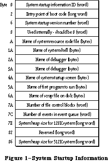 Figure 1–System Startup Information
The System file contains standard values for these fields that are used in formatting a volume. (The values for certain fields, such as the number of file control blocks and the system heap size, depend on the machine that’s running and are computed at system startup time.) You should have no reason to access the information in these fields; they’re shown only for your information.
The system startup information ID is used to verify that the blocks contain system startup information.
The version number distinguishes between different versions of system startup information. A version number of $44 means that the blocks contain executable code. The code typically directly follows the startup information, and the entry code for such code is stored just before the version number (at byte 2).
Following the version number are a number of names that identify standard files used or executed during system startup. These names can be up to 15 characters long, and must be preceded by a length byte.
_______________________________________________________________________________
»'INIT' Resource 31
The 'INIT' 31 resource (introduced in the System Resource File chapter) has been modified to provide a way for 'INIT' resources to request space in the system heap zone. Whenever 'INIT' 31 opens your file of type 'INIT' or 'RDEV', it now looks for a resource of type 'sysz' with an ID = 0. The 'sysz' resource can be any size you like, as long as the first long word contains the number of bytes of system heap space needed by the 'INIT' resources in your 'RDEV' or
'INIT' file. 'INIT' 31 calls the SetApplBase procedure as needed to meet the space request. For each 'INIT' resource loaded from the 'RDEV' or 'INIT' file, 'INIT' 31 guarantees at least 16K of contiguous space in the system heap.
Although the System Resource File chapter discussed allocation of space from the address contained in the global variable BufPtr, programmers are encouraged to take advantage of the 'sysz' resource for the memory needs of their 'INIT' resources.
_______________________________________________________________________________
»Timing Information
At system startup, a number of global variables are initialized with timing information useful to assembly-language programmers:
Variable Contents
TimeDBRA The number of times the DBRA instruction can be
executed per millisecond.
TimeSCCDB The number of times the SCC can be accessed per millisecond.
TimeSCSIDB The number of times the SCSI can be accessed per millisecond.
Access of the SCC and SCSI chips consists of the following two instructions
(where register A0 points at the base address of the respective chips):
@1 BTST #0,(A0)
DBRA D0,@1
_______________________________________________________________________________
»START MANAGER ROUTINES
_______________________________________________________________________________
The routines described below are used by the Start Manager for configuring the system startup process. Only a very few advanced programmers who wish to implement a different operating system on the Macintosh will ever need to use these routines.
GetDefaultStartup, SetDefaultStartup, GetTimeout, and Set Timeout are implemented for both the Macintosh SE and the Macintosh II. GetVideoDefault, SetVideoDefault, GetOSDefault, and SetOSDefault are implemented only on the Macintosh II.
Routine parameters for GetDefaultStartup, SetDefaultStartup, GetVideoDefault, SetVideoDefault, GetOSDefault, and SetOSDefault are passed and returned using parameter blocks.
Assembly-language note: When you call GetDefaultStartup, SetDefaultStartup,
GetVideoDefault, SetVideoDefault, GetOSDefault, and
SetOSDefault, A0 must point to a parameter block that
will contain the parameters passed to, or returned
by, the routine.
The DefStartRec parameter block used by GetDefaultStartup and SetDefaultStartup has the following structure:
TYPE DefStartType = (slotDev,scsiDev);
DefStartRec = RECORD
CASE DefStartType OF
slotDev:
sdExtDevID: SignedByte; {external device ID}
sdPartition: SignedByte; {reserved}
sdSlotNum: SignedByte; {slot number}
sdSRsrcID: SignedByte; {SResourceID}
scsiDev:
sdReserved1: SignedByte; {reserved}
sdReserved2: SignedByte; {reserved}
sdRefNum: INTEGER {driver reference number}
END;
DefStartPtr = ^DefStartRec
The two variants of the StartDevPBRec correspond to two types of devices that can currently be connected. The slotDev variant contains information about slot devices, while the scsiDev variant describes a device connected through the SCSI port.
PROCEDURE GetDefaultStartup (paramBlock: DefStartPtr);
--> 0 sdExtDevID byte or --> 0 sdReserved1 byte
--> 1 sdPartition byte --> 1 sdReserved2 byte
--> 2 sdSlotNum byte --> 2 sdRefNum word
--> 3 sdSRsrcID byte
GetDefaultStartup returns information about the default startup device from parameter RAM. To determine which variant to use, you need to look at the sdRefNum field. If this field contains a negative number, it’s the driver reference number for an SCSI device, which is all you need to know.
(SDReserved1 and sdReserved2 are reserved for future use.)
If sdRefNum contains a positive number, you’ll need to access the information in the slotDev variant. SDExtDevID is specified by a slot’s driver; it identifies one of perhaps several devices that are connected through a single slot. SDSlotNum is the slot number ($9 thru E) and sdSRsrcID is the sResource ID; see the Slot Manager chapter for details.
PROCEDURE SetDefaultStartup (paramBlock: DefStartPtr);
<-- 0 sdExtDevID byte or <-- 0 sdReserved1 byte
<-- 1 sdPartition byte <-- 1 sdReserved2 byte
<-- 2 sdSlotNum byte <-- 2 sdRefNum word
<-- 3 sdSRsrcID byte
SetDefaultStartup specifies a device as the default startup device. For a slot device, sdExtDevID (specified by the slot’s driver) identifies one of perhaps several devices that are connected through a single slot. SDSlotNum is the slot number ($9 thru E) and sdSRsrcID is the sResource ID; see the Slot Manager chapter for details.
In the case of an SCSI device, sdRefNum contains the reference number; to specify no device as default (meaning that the first available device will be chosen at startup), pass 0 in sdRefNum. SDReserved1 and sdReserved2 are reserved for future use and should be 0.
The GetVideoDefault and SetVideoDefault calls use the following parameter block to pass information about the default video device:
TYPE DefVideoRec = RECORD
sdSlot: SignedByte; {slot number}
sdSResource: SignedByte; {sResource ID}
END;
DefVideoPtr = ^DefVideoRec
PROCEDURE GetVideoDefault (paramBlock: DefVideoPtr);
Trap macro _GetVideoDefault
Parameter block
--> 0 sdSlot byte
--> 1 sdSResource byte
GetVideoDefault returns the slot number and sResourceID of the default video device. If sdSlot returns 0, there is no default video device and the first available video device will be chosen.
PROCEDURE SetVideoDefault (paramBlock: DefVideoPtr);
Trap macro _SetVideoDefault
Parameter block
<-- 0 sdSlot byte
<-- 1 sdSResource byte
SetVideoDefault makes the device with the given slot number and sResourceID the default video device.
The GetOSDefault and SetOSDefault calls use the following parameter block to pas information about the default operating system:
TYPE DefOSRec = RECORD
sdReserved: SignedByte; {reserved--should be 0}
sdOSType: SignedByte; {operating system type}
END;
DefOSPtr = ^DefOSRec
PROCEDURE GetOSDefault (paramBlock: DefOSPtr);
Trap macro _GetOSDefault
Parameter block
--> 0 sdReserved byte
--> 1 sdOSType byte
GetOSDefault returns a value in sdOSType identifying the operating system to be used at startup. The sdReserved parameter currently returns 0; it’s reserved for future use. This call is generally used only with partitioned devices containing multiple operating systems; for more details, see the SCSI Manager chapter.
PROCEDURE SetOSDefault (paramBlock: DefOSPtr);
Trap macro _SetOSDefault
Parameter block
<-- 0 sdReserved byte
<-- 1 sdOSType byte
SetOSDefault specifies in sdOSType the operating system to be used at startup. The sdReserved parameter is reserved for future use and should be 0. This call is generally used only with partitioned devices containing multiple operating systems; for details, see the SCSI Manager chapter.
PROCEDURE GetTimeout (VAR count: INTEGER);
Trap macro _GetTimeout
On exit D0: count (word)
Note: The _GetTimeout macro is actually not a trap, but expands to invoke
the trap macro _InternalWait with a routine selector of 0 pushed on
the stack.
GetTimeout returns in count the number of seconds the system will wait for the internal hard disk to respond. A value of 0 indicates the default timeout of 15 seconds.
PROCEDURE SetTimeout (count: INTEGER);
Trap macro _SetTimeout
On entry D0: count (word)
Note: The _SetTimeout macro is actually not a trap, but expands to invoke
the trap macro _InternalWait with a routine selector of 1 pushed on
the stack.
SetTimeout lets you specify in count the number of seconds the system should wait for the internal hard disk to respond. The maximum value is 31 seconds; a value of 0 indicates the default timeout of 15 seconds.
_______________________________________________________________________________
»SUMMARY OF THE START MANAGER
_______________________________________________________________________________
Data Types
TYPE
DefStartType = (slotDev,scsiDev);
DefStartPtr = ^DefStartRec
DefStartRec = RECORD
CASE DefStartType OF
slotDev:
sdExtDevID: SignedByte; {external device ID}
sdPartition: SignedByte; {reserved}
sdSlotNum: SignedByte; {slot number}
sdSRsrcID: SignedByte; {SResourceID}
scsiDev:
sdReserved1: SignedByte; {reserved}
sdReserved2: SignedByte; {reserved}
sdRefNum: INTEGER {driver reference number}
END;
DefVideoPtr = ^DefVideoRec
DefVideoRec = RECORD
sdSlot: SignedByte; {slot number}
sdSResource: SignedByte; {sResource ID}
END;
DefOSPtr = ^DefOSRec
DefOSRec = RECORD
sdReserved: SignedByte; {reserved--should be 0}
sdOSType: SignedByte; {operating system type}
END;
_______________________________________________________________________________
Routines
PROCEDURE GetDefaultStartup (paramBlock: DefStartPtr);
--> 0 sdExtDevID byte or --> 0 sdReserved1 byte
--> 1 sdPartition byte --> 1 sdReserved2 byte
--> 2 sdSlotNum byte --> 2 sdRefNum word
--> 3 sdSRsrcID byte
PROCEDURE SetDefaultStartup (paramBlock: DefStartPtr);
<-- 0 sdExtDevID byte or <-- 0 sdReserved1 byte
<-- 1 sdPartition byte <-- 1 sdReserved2 byte
<-- 2 sdSlotNum byte <-- 2 sdRefNum word
<-- 3 sdSRsrcID byte
PROCEDURE GetVideoDefault (paramBlock: DefVideoPtr);
--> 0 sdSlot byte
--> 1 sdSResource byte
PROCEDURE SetVideoDefault (paramBlock: DefVideoPtr);
<-- 0 sdSlot byte
<-- 1 sdSResource byte
PROCEDURE GetOSDefault (paramBlock: DefOSPtr);
--> 0 sdReserved byte
--> 1 sdOSType byte
PROCEDURE SetOSDefault (paramBlock: DefOSPtr);
<-- 0 sdReserved byte
<-- 1 sdOSType byte
PROCEDURE GetTimeout (VAR count: INTEGER);
PROCEDURE SetTimeout (count: INTEGER);
_______________________________________________________________________________
Assembly-Language Information
Structure of Default Startup Device Parameter Block (Slot)
sdExtDevID External device ID (byte)
sdPartition Reserved—should be 0 (byte)
sdSlotNum Slot number (byte)
sdSRsrcID SResource ID (byte)
Structure of Default Startup Device Parameter Block (SCSI)
sdReserved1 Reserved—should be 0 (byte)
sdReserved2 Reserved—should be 0 (byte
sdRefNum Driver reference number (word)
Structure of Default Video Device Parameter Block
sdSlot Slot number (byte)
sdSResource SResource ID (byte)
Structure of Default OS Parameter Block
sdReserved Reserved—should be 0 (byte)
sdOSType Operating system type (byte)
_______________________________________________________________________________
Routines
Trap macro On entry On Exit
_GetVideoDefault A0: ptr to param block A0: ptr to param block
_SetVideoDefault A0: ptr to param block A0: ptr to param block
_GetOSDefault A0: ptr to param block A0: ptr to param block
_SetOSDefault A0: ptr to param block A0: ptr to param block
_GetTimeout D0: count (word)
_SetTimeout D0: count (word)
Note: The GetTimeout and SetTimeout macros expand to invoke the trap macro
_InternalWait with routine selectors of 0 and 1 respectively pushed
on the stack.)
_______________________________________________________________________________
Variables
CPUFlag Microprocessor in use (word)
TimeDBRA Number of times the DBRA instruction can be executed
per millisecond (word)
TimeSCCDB Number of times the SCC can be accessed per millisecond (word)
TimeSCSIDB Number of times the SCSI can be accessed per millisecond (word)
Further Reference:
_______________________________________________________________________________
Technical Note #14, The INIT 31 Mechanism
Technical Note #256, Stand-Alone Code, ad nauseam
“Macintosh Family Hardware Reference”
Figure 1–System Startup Information
The System file contains standard values for these fields that are used in formatting a volume. (The values for certain fields, such as the number of file control blocks and the system heap size, depend on the machine that’s running and are computed at system startup time.) You should have no reason to access the information in these fields; they’re shown only for your information.
The system startup information ID is used to verify that the blocks contain system startup information.
The version number distinguishes between different versions of system startup information. A version number of $44 means that the blocks contain executable code. The code typically directly follows the startup information, and the entry code for such code is stored just before the version number (at byte 2).
Following the version number are a number of names that identify standard files used or executed during system startup. These names can be up to 15 characters long, and must be preceded by a length byte.
_______________________________________________________________________________
»'INIT' Resource 31
The 'INIT' 31 resource (introduced in the System Resource File chapter) has been modified to provide a way for 'INIT' resources to request space in the system heap zone. Whenever 'INIT' 31 opens your file of type 'INIT' or 'RDEV', it now looks for a resource of type 'sysz' with an ID = 0. The 'sysz' resource can be any size you like, as long as the first long word contains the number of bytes of system heap space needed by the 'INIT' resources in your 'RDEV' or
'INIT' file. 'INIT' 31 calls the SetApplBase procedure as needed to meet the space request. For each 'INIT' resource loaded from the 'RDEV' or 'INIT' file, 'INIT' 31 guarantees at least 16K of contiguous space in the system heap.
Although the System Resource File chapter discussed allocation of space from the address contained in the global variable BufPtr, programmers are encouraged to take advantage of the 'sysz' resource for the memory needs of their 'INIT' resources.
_______________________________________________________________________________
»Timing Information
At system startup, a number of global variables are initialized with timing information useful to assembly-language programmers:
Variable Contents
TimeDBRA The number of times the DBRA instruction can be
executed per millisecond.
TimeSCCDB The number of times the SCC can be accessed per millisecond.
TimeSCSIDB The number of times the SCSI can be accessed per millisecond.
Access of the SCC and SCSI chips consists of the following two instructions
(where register A0 points at the base address of the respective chips):
@1 BTST #0,(A0)
DBRA D0,@1
_______________________________________________________________________________
»START MANAGER ROUTINES
_______________________________________________________________________________
The routines described below are used by the Start Manager for configuring the system startup process. Only a very few advanced programmers who wish to implement a different operating system on the Macintosh will ever need to use these routines.
GetDefaultStartup, SetDefaultStartup, GetTimeout, and Set Timeout are implemented for both the Macintosh SE and the Macintosh II. GetVideoDefault, SetVideoDefault, GetOSDefault, and SetOSDefault are implemented only on the Macintosh II.
Routine parameters for GetDefaultStartup, SetDefaultStartup, GetVideoDefault, SetVideoDefault, GetOSDefault, and SetOSDefault are passed and returned using parameter blocks.
Assembly-language note: When you call GetDefaultStartup, SetDefaultStartup,
GetVideoDefault, SetVideoDefault, GetOSDefault, and
SetOSDefault, A0 must point to a parameter block that
will contain the parameters passed to, or returned
by, the routine.
The DefStartRec parameter block used by GetDefaultStartup and SetDefaultStartup has the following structure:
TYPE DefStartType = (slotDev,scsiDev);
DefStartRec = RECORD
CASE DefStartType OF
slotDev:
sdExtDevID: SignedByte; {external device ID}
sdPartition: SignedByte; {reserved}
sdSlotNum: SignedByte; {slot number}
sdSRsrcID: SignedByte; {SResourceID}
scsiDev:
sdReserved1: SignedByte; {reserved}
sdReserved2: SignedByte; {reserved}
sdRefNum: INTEGER {driver reference number}
END;
DefStartPtr = ^DefStartRec
The two variants of the StartDevPBRec correspond to two types of devices that can currently be connected. The slotDev variant contains information about slot devices, while the scsiDev variant describes a device connected through the SCSI port.
PROCEDURE GetDefaultStartup (paramBlock: DefStartPtr);
--> 0 sdExtDevID byte or --> 0 sdReserved1 byte
--> 1 sdPartition byte --> 1 sdReserved2 byte
--> 2 sdSlotNum byte --> 2 sdRefNum word
--> 3 sdSRsrcID byte
GetDefaultStartup returns information about the default startup device from parameter RAM. To determine which variant to use, you need to look at the sdRefNum field. If this field contains a negative number, it’s the driver reference number for an SCSI device, which is all you need to know.
(SDReserved1 and sdReserved2 are reserved for future use.)
If sdRefNum contains a positive number, you’ll need to access the information in the slotDev variant. SDExtDevID is specified by a slot’s driver; it identifies one of perhaps several devices that are connected through a single slot. SDSlotNum is the slot number ($9 thru E) and sdSRsrcID is the sResource ID; see the Slot Manager chapter for details.
PROCEDURE SetDefaultStartup (paramBlock: DefStartPtr);
<-- 0 sdExtDevID byte or <-- 0 sdReserved1 byte
<-- 1 sdPartition byte <-- 1 sdReserved2 byte
<-- 2 sdSlotNum byte <-- 2 sdRefNum word
<-- 3 sdSRsrcID byte
SetDefaultStartup specifies a device as the default startup device. For a slot device, sdExtDevID (specified by the slot’s driver) identifies one of perhaps several devices that are connected through a single slot. SDSlotNum is the slot number ($9 thru E) and sdSRsrcID is the sResource ID; see the Slot Manager chapter for details.
In the case of an SCSI device, sdRefNum contains the reference number; to specify no device as default (meaning that the first available device will be chosen at startup), pass 0 in sdRefNum. SDReserved1 and sdReserved2 are reserved for future use and should be 0.
The GetVideoDefault and SetVideoDefault calls use the following parameter block to pass information about the default video device:
TYPE DefVideoRec = RECORD
sdSlot: SignedByte; {slot number}
sdSResource: SignedByte; {sResource ID}
END;
DefVideoPtr = ^DefVideoRec
PROCEDURE GetVideoDefault (paramBlock: DefVideoPtr);
Trap macro _GetVideoDefault
Parameter block
--> 0 sdSlot byte
--> 1 sdSResource byte
GetVideoDefault returns the slot number and sResourceID of the default video device. If sdSlot returns 0, there is no default video device and the first available video device will be chosen.
PROCEDURE SetVideoDefault (paramBlock: DefVideoPtr);
Trap macro _SetVideoDefault
Parameter block
<-- 0 sdSlot byte
<-- 1 sdSResource byte
SetVideoDefault makes the device with the given slot number and sResourceID the default video device.
The GetOSDefault and SetOSDefault calls use the following parameter block to pas information about the default operating system:
TYPE DefOSRec = RECORD
sdReserved: SignedByte; {reserved--should be 0}
sdOSType: SignedByte; {operating system type}
END;
DefOSPtr = ^DefOSRec
PROCEDURE GetOSDefault (paramBlock: DefOSPtr);
Trap macro _GetOSDefault
Parameter block
--> 0 sdReserved byte
--> 1 sdOSType byte
GetOSDefault returns a value in sdOSType identifying the operating system to be used at startup. The sdReserved parameter currently returns 0; it’s reserved for future use. This call is generally used only with partitioned devices containing multiple operating systems; for more details, see the SCSI Manager chapter.
PROCEDURE SetOSDefault (paramBlock: DefOSPtr);
Trap macro _SetOSDefault
Parameter block
<-- 0 sdReserved byte
<-- 1 sdOSType byte
SetOSDefault specifies in sdOSType the operating system to be used at startup. The sdReserved parameter is reserved for future use and should be 0. This call is generally used only with partitioned devices containing multiple operating systems; for details, see the SCSI Manager chapter.
PROCEDURE GetTimeout (VAR count: INTEGER);
Trap macro _GetTimeout
On exit D0: count (word)
Note: The _GetTimeout macro is actually not a trap, but expands to invoke
the trap macro _InternalWait with a routine selector of 0 pushed on
the stack.
GetTimeout returns in count the number of seconds the system will wait for the internal hard disk to respond. A value of 0 indicates the default timeout of 15 seconds.
PROCEDURE SetTimeout (count: INTEGER);
Trap macro _SetTimeout
On entry D0: count (word)
Note: The _SetTimeout macro is actually not a trap, but expands to invoke
the trap macro _InternalWait with a routine selector of 1 pushed on
the stack.
SetTimeout lets you specify in count the number of seconds the system should wait for the internal hard disk to respond. The maximum value is 31 seconds; a value of 0 indicates the default timeout of 15 seconds.
_______________________________________________________________________________
»SUMMARY OF THE START MANAGER
_______________________________________________________________________________
Data Types
TYPE
DefStartType = (slotDev,scsiDev);
DefStartPtr = ^DefStartRec
DefStartRec = RECORD
CASE DefStartType OF
slotDev:
sdExtDevID: SignedByte; {external device ID}
sdPartition: SignedByte; {reserved}
sdSlotNum: SignedByte; {slot number}
sdSRsrcID: SignedByte; {SResourceID}
scsiDev:
sdReserved1: SignedByte; {reserved}
sdReserved2: SignedByte; {reserved}
sdRefNum: INTEGER {driver reference number}
END;
DefVideoPtr = ^DefVideoRec
DefVideoRec = RECORD
sdSlot: SignedByte; {slot number}
sdSResource: SignedByte; {sResource ID}
END;
DefOSPtr = ^DefOSRec
DefOSRec = RECORD
sdReserved: SignedByte; {reserved--should be 0}
sdOSType: SignedByte; {operating system type}
END;
_______________________________________________________________________________
Routines
PROCEDURE GetDefaultStartup (paramBlock: DefStartPtr);
--> 0 sdExtDevID byte or --> 0 sdReserved1 byte
--> 1 sdPartition byte --> 1 sdReserved2 byte
--> 2 sdSlotNum byte --> 2 sdRefNum word
--> 3 sdSRsrcID byte
PROCEDURE SetDefaultStartup (paramBlock: DefStartPtr);
<-- 0 sdExtDevID byte or <-- 0 sdReserved1 byte
<-- 1 sdPartition byte <-- 1 sdReserved2 byte
<-- 2 sdSlotNum byte <-- 2 sdRefNum word
<-- 3 sdSRsrcID byte
PROCEDURE GetVideoDefault (paramBlock: DefVideoPtr);
--> 0 sdSlot byte
--> 1 sdSResource byte
PROCEDURE SetVideoDefault (paramBlock: DefVideoPtr);
<-- 0 sdSlot byte
<-- 1 sdSResource byte
PROCEDURE GetOSDefault (paramBlock: DefOSPtr);
--> 0 sdReserved byte
--> 1 sdOSType byte
PROCEDURE SetOSDefault (paramBlock: DefOSPtr);
<-- 0 sdReserved byte
<-- 1 sdOSType byte
PROCEDURE GetTimeout (VAR count: INTEGER);
PROCEDURE SetTimeout (count: INTEGER);
_______________________________________________________________________________
Assembly-Language Information
Structure of Default Startup Device Parameter Block (Slot)
sdExtDevID External device ID (byte)
sdPartition Reserved—should be 0 (byte)
sdSlotNum Slot number (byte)
sdSRsrcID SResource ID (byte)
Structure of Default Startup Device Parameter Block (SCSI)
sdReserved1 Reserved—should be 0 (byte)
sdReserved2 Reserved—should be 0 (byte
sdRefNum Driver reference number (word)
Structure of Default Video Device Parameter Block
sdSlot Slot number (byte)
sdSResource SResource ID (byte)
Structure of Default OS Parameter Block
sdReserved Reserved—should be 0 (byte)
sdOSType Operating system type (byte)
_______________________________________________________________________________
Routines
Trap macro On entry On Exit
_GetVideoDefault A0: ptr to param block A0: ptr to param block
_SetVideoDefault A0: ptr to param block A0: ptr to param block
_GetOSDefault A0: ptr to param block A0: ptr to param block
_SetOSDefault A0: ptr to param block A0: ptr to param block
_GetTimeout D0: count (word)
_SetTimeout D0: count (word)
Note: The GetTimeout and SetTimeout macros expand to invoke the trap macro
_InternalWait with routine selectors of 0 and 1 respectively pushed
on the stack.)
_______________________________________________________________________________
Variables
CPUFlag Microprocessor in use (word)
TimeDBRA Number of times the DBRA instruction can be executed
per millisecond (word)
TimeSCCDB Number of times the SCC can be accessed per millisecond (word)
TimeSCSIDB Number of times the SCSI can be accessed per millisecond (word)
Further Reference:
_______________________________________________________________________________
Technical Note #14, The INIT 31 Mechanism
Technical Note #256, Stand-Alone Code, ad nauseam
“Macintosh Family Hardware Reference”
The System Error Handler
_______________________________________________________________________________
THE SYSTEM ERROR HANDLER
_______________________________________________________________________________
About This Chapter
About the System Error Handler
Recovering From System Errors
System Error Alert Tables
System Error Handler Routine
Summary of the System Error Handler
_______________________________________________________________________________
»ABOUT THIS CHAPTER
_______________________________________________________________________________
The System Error Handler is the part of the Operating System that assumes control when a fatal system error occurs. This chapter introduces you to the System Error Handler and describes how your application can recover from system errors.
You’ll already need to be somewhat familiar with most of the User Interface Toolbox and the rest of the Operating System.
_______________________________________________________________________________
»ABOUT THE SYSTEM ERROR HANDLER
_______________________________________________________________________________
The System Error Handler assumes control when a fatal system error occurs. Its main function is to display an alert box with an error message (called a system error alert) and provide a mechanism for the application to resume execution.
Note: The system error alerts simply identify the type of problem encountered
and, in some cases, the part of the Toolbox or Operating System
involved. They don’t, however, tell you where in your application code
the failure occurred.
Because a system error usually indicates that a very low-level part of the system has failed, the System Error Handler performs its duties by using as little of the system as possible. It requires only the following:
• The trap dispatcher is operative.
• The Font Manager procedure InitFonts has been called (it’s called when
the system starts up).
• Register A7 points to a reasonable place in memory (for example, not to
the main screen buffer).
• A few important system data structures aren’t too badly damaged.
The System Error Handler doesn’t require the Memory Manager to be operative.
The content of the alert box displayed is determined by a system error alert table, a resource stored in the system resource file. There are two different system error alert tables: a system startup alert table used when the system starts up, and a user alert table for informing the user of system errors.
The system startup alerts are used to display messages at system startup such as the “Welcome to Macintosh” message (Figure 1). They’re displayed by the System Error Handler instead of the Dialog Manager because the System Error Handler needs very little of the system to operate.
The user alerts (Figure 2) notify the user of system errors. The bottom right corner of a user alert contains a system error ID that identifies the error. Usually the message “Sorry, a system error occurred”, a Restart button, and a Resume button are also shown. If the Finder can’t be found on a disk, the message “Can’t load the finder” and a Restart button will be shown. The Macintosh will attempt to restart if the user clicks the Restart button, and the application will attempt to resume execution if the user clicks the Resume button.
 Figure 1–System Startup Alert
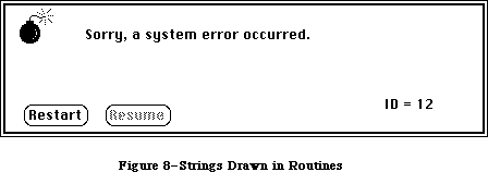 Figure 2–User Alert
The “Please insert the disk:” message displayed by the File Manager is also a user alert; however, unlike the other alerts, it’s displayed in a dialog box.
The summary at the end of this chapter lists the system error IDs for the various user alerts, as well as the system startup alert messages.
A new system error, user alert ID 84, has been added. This error results when the Menu Manager tries to access a menu that’s been purged.
_______________________________________________________________________________
»RECOVERING FROM SYSTEM ERRORS
_______________________________________________________________________________
An application recovers from a system error by means of a resume procedure. You pass a pointer to your resume procedure when you call the Dialog Manager procedure InitDialogs. When the user clicks the Resume button in a system error alert, the System Error Handler attempts to restore the state of the system and then calls your resume procedure.
Assembly-language note: The System Error Handler actually restores the value
of register A5 to what it was before the system error
occurred, sets the stack pointer to the address stored
in the global variable CurStackBase (throwing away the
stack), and then jumps to your resume procedure.
If you don’t have a resume procedure, you’ll pass NIL to InitDialogs (and the Resume button in the system error alert will be dimmed).
_______________________________________________________________________________
»SYSTEM ERROR ALERT TABLES
_______________________________________________________________________________
This section describes the data structures that define the alert boxes displayed by the System Error Handler; this information is provided mainly to allow you to edit and translate the messages displayed in the alerts. Rearranging the alert tables or creating new ones is discouraged because the Operating System depends on having the alert information stored in a very specific and constant way.
In the system resource file, the system error alerts have the following resource types and IDs:
Table Resource type Resource ID
System startup alert table 'DSAT' 0
User alert table 'INIT' 2
Assembly-language note: The global variable DSAlertTab contains a pointer to
the current system error alert table. DSAlertTab
points to the system startup alert table when the
system is starting up; then it’s changed to point to
the user alert table.
A system error alert table consists of a word indicating the number of entries in the table, followed by alert, text, icon, button, and procedure definitions, all of which are explained below. The first definition in a system error alert table is an alert definition that applies to all system errors that don’t have their own alert definition. The rest of the definitions within the alert table needn’t be in any particular order, nor do the definitions of one type need to be grouped together. The first two words in every definition are used for the same purpose: The first word contains an ID number identifying the definition, and the second specifies the length of the rest of the definition in bytes.
An alert definition specifies the IDs of the text, icon, button, and procedure definitions that together determine the appearance and operation of the alert box that will be drawn (Figure 3). The ID of an alert definition is the system error ID that the alert pertains to. The System Error Handler uses the system error ID to locate the alert definition. The alert definition specifies the IDs of the other definitions needed to create the alert; 0 is specified if the alert doesn’t include any items of that type.
A text definition specifies the text that will be drawn in the system error alert (Figure 4). Each alert definition refers to two text definitions; the secondary text definition allows a second line of text to be added to the alert message. (No more than two lines of text may be displayed.) The pen location at which QuickDraw will begin drawing the text is given as a point in global coordinates. The actual characters that comprise the text are suffixed by one NUL character (ASCII code 0).
Warning: The slash character (/) can’t be used in the text.
Figure 2–User Alert
The “Please insert the disk:” message displayed by the File Manager is also a user alert; however, unlike the other alerts, it’s displayed in a dialog box.
The summary at the end of this chapter lists the system error IDs for the various user alerts, as well as the system startup alert messages.
A new system error, user alert ID 84, has been added. This error results when the Menu Manager tries to access a menu that’s been purged.
_______________________________________________________________________________
»RECOVERING FROM SYSTEM ERRORS
_______________________________________________________________________________
An application recovers from a system error by means of a resume procedure. You pass a pointer to your resume procedure when you call the Dialog Manager procedure InitDialogs. When the user clicks the Resume button in a system error alert, the System Error Handler attempts to restore the state of the system and then calls your resume procedure.
Assembly-language note: The System Error Handler actually restores the value
of register A5 to what it was before the system error
occurred, sets the stack pointer to the address stored
in the global variable CurStackBase (throwing away the
stack), and then jumps to your resume procedure.
If you don’t have a resume procedure, you’ll pass NIL to InitDialogs (and the Resume button in the system error alert will be dimmed).
_______________________________________________________________________________
»SYSTEM ERROR ALERT TABLES
_______________________________________________________________________________
This section describes the data structures that define the alert boxes displayed by the System Error Handler; this information is provided mainly to allow you to edit and translate the messages displayed in the alerts. Rearranging the alert tables or creating new ones is discouraged because the Operating System depends on having the alert information stored in a very specific and constant way.
In the system resource file, the system error alerts have the following resource types and IDs:
Table Resource type Resource ID
System startup alert table 'DSAT' 0
User alert table 'INIT' 2
Assembly-language note: The global variable DSAlertTab contains a pointer to
the current system error alert table. DSAlertTab
points to the system startup alert table when the
system is starting up; then it’s changed to point to
the user alert table.
A system error alert table consists of a word indicating the number of entries in the table, followed by alert, text, icon, button, and procedure definitions, all of which are explained below. The first definition in a system error alert table is an alert definition that applies to all system errors that don’t have their own alert definition. The rest of the definitions within the alert table needn’t be in any particular order, nor do the definitions of one type need to be grouped together. The first two words in every definition are used for the same purpose: The first word contains an ID number identifying the definition, and the second specifies the length of the rest of the definition in bytes.
An alert definition specifies the IDs of the text, icon, button, and procedure definitions that together determine the appearance and operation of the alert box that will be drawn (Figure 3). The ID of an alert definition is the system error ID that the alert pertains to. The System Error Handler uses the system error ID to locate the alert definition. The alert definition specifies the IDs of the other definitions needed to create the alert; 0 is specified if the alert doesn’t include any items of that type.
A text definition specifies the text that will be drawn in the system error alert (Figure 4). Each alert definition refers to two text definitions; the secondary text definition allows a second line of text to be added to the alert message. (No more than two lines of text may be displayed.) The pen location at which QuickDraw will begin drawing the text is given as a point in global coordinates. The actual characters that comprise the text are suffixed by one NUL character (ASCII code 0).
Warning: The slash character (/) can’t be used in the text.
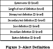 Figure 3–Alert Definition
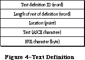 Figure 4–Text Definition
An icon definition specifies the icon that will be drawn in the system error alert (Figure 5). The location of the icon is given as a rectangle in global coordinates. The 128 bytes that comprise the icon complete the definition.
Figure 4–Text Definition
An icon definition specifies the icon that will be drawn in the system error alert (Figure 5). The location of the icon is given as a rectangle in global coordinates. The 128 bytes that comprise the icon complete the definition.
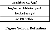 Figure 5–Icon Definition
A procedure definition specifies a procedure that will be executed whenever the system error alert is drawn (Figure 6). Procedure definitions are also used to specify the action to be taken when a particular button is pressed, as described below. Most of a procedure definition is simply the code comprising the procedure.
Figure 5–Icon Definition
A procedure definition specifies a procedure that will be executed whenever the system error alert is drawn (Figure 6). Procedure definitions are also used to specify the action to be taken when a particular button is pressed, as described below. Most of a procedure definition is simply the code comprising the procedure.
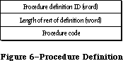 Figure 6–Procedure Definition
A button definition specifies the button(s) that will be drawn in the system error alert (Figure 7). It indicates the number of buttons that will be drawn, followed by that many six-word groups, each specifying the text, location, and operation of a button.
Figure 6–Procedure Definition
A button definition specifies the button(s) that will be drawn in the system error alert (Figure 7). It indicates the number of buttons that will be drawn, followed by that many six-word groups, each specifying the text, location, and operation of a button.
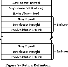 Figure 7–Button Definition
The first word of each six-word group contains a string ID (explained below) specifying the text that will be drawn inside the button. The button’s location is given as a rectangle in global coordinates. The last word contains a procedure definition ID identifying the code to be executed when the button is clicked.
The text that will be drawn inside each button is specified by the data structure shown in Figure 8. The first word contains a string ID identifying the string and the second indicates the length of the string in bytes. The actual characters of the string follow.
Each alert has two button definitions; these definitions have sequential button definition IDs (such as 60 and 61). The button definition ID of the first definition is placed in the alert definition. This definition is used if no resume procedure has been specified (with a call to the Dialog Manager’s InitDialogs procedure). If a resume procedure has been specified, the System Error Handler adds 1 to the button definition ID specified in the alert definition and so uses the second
Figure 7–Button Definition
The first word of each six-word group contains a string ID (explained below) specifying the text that will be drawn inside the button. The button’s location is given as a rectangle in global coordinates. The last word contains a procedure definition ID identifying the code to be executed when the button is clicked.
The text that will be drawn inside each button is specified by the data structure shown in Figure 8. The first word contains a string ID identifying the string and the second indicates the length of the string in bytes. The actual characters of the string follow.
Each alert has two button definitions; these definitions have sequential button definition IDs (such as 60 and 61). The button definition ID of the first definition is placed in the alert definition. This definition is used if no resume procedure has been specified (with a call to the Dialog Manager’s InitDialogs procedure). If a resume procedure has been specified, the System Error Handler adds 1 to the button definition ID specified in the alert definition and so uses the second
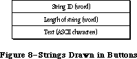 Figure 8–Strings Drawn in Buttons
button definition. In this definition, the procedure for the Resume button attempts to restore the state of the system and calls the resume procedure that was specified with InitDialogs.
_______________________________________________________________________________
»SYSTEM ERROR HANDLER ROUTINE
_______________________________________________________________________________
The System Error Handler has only one routine, SysError, described below. Most application programs won’t have any reason to call it. The system itself calls SysError whenever a system error occurs, and most applications need only be concerned with recovering from the error and resuming execution.
PROCEDURE SysError (errorCode: INTEGER);
Trap macro _SysError
On entry D0: errorCode (word)
On exit All registers changed
SysError generates a system error with the ID specified by the errorCode parameter.
It takes the following precise steps:
1. It saves all registers and the stack pointer.
2. It stores the system error ID in a global variable (named DSErrCode).
3. It checks to see whether there’s a system error alert table in memory
(by testing whether the global variable DSAlertTab is 0); if there
isn’t, it draws the “sad Macintosh” icon.
4. It allocates memory for QuickDraw globals on the stack, initializes
QuickDraw, and initializes a grafPort in which the alert box will be
drawn.
5. It checks the system error ID. If the system error ID is negative, the
alert box isn’t redrawn (this is used for system startup alerts, which
can display a sequence of consecutive messages in the same box). If the
system error ID doesn’t correspond to an entry in the system error alert
table, the default alert definition at the start of the table will be
used, displaying the message “Sorry, a system error occurred”.
6. It draws an alert box (in the rectangle specified by the global variable
DSAlertRect).
7. If the text definition IDs in the alert definition for this alert aren’t
0, it draws both strings.
8. If the icon definition ID in the alert definition isn’t 0, it draws the
icon.
9. If the procedure definition ID in the alert definition isn’t 0, it
invokes the procedure with the specified ID.
10. If the button definition ID in the alert definition is 0, it returns
control to the procedure that called it (this is used during the disk-
switch alert to return control to the File Manager after the “Please
insert the disk:” message has been displayed).
11. If there’s a resume procedure, it increments the button definition ID
by 1.
12. It draws the buttons.
13. It hit-tests the buttons and calls the corresponding procedure code
when a button is pressed. If there’s no procedure code, it returns to
the procedure that called it.
_______________________________________________________________________________
»SUMMARY OF THE SYSTEM ERROR HANDLER
_______________________________________________________________________________
Routines
PROCEDURE SysError (errorCode: INTEGER);
_______________________________________________________________________________
User Alerts
ID Explanation
1 Bus error: Invalid memory reference; happens only on a Macintosh XL
2 Address error: Word or long-word reference made to an odd address
3 Illegal instruction: The MC68000 received an instruction it didn’t
recognize.
4 Zero divide: Signed Divide (DIVS) or Unsigned Divide (DIVU)
instruction with a divisor of 0 was executed.
5 Check exception: Check Register Against Bounds (CHK) instruction was
executed and failed. Pascal “value out of range” errors are usually
reported in this way.
6 TrapV exception: Trap On Overflow (TRAPV) instruction was executed
and failed.
7 Privilege violation: Macintosh always runs in supervisor mode;
perhaps an erroneous Return From Execution (RTE) instruction was
executed.
8 Trace exception: The trace bit in the status register is set.
9 Line 1010 exception: The 1010 trap dispatcher has failed.
10 Line 1111 exception: Unimplemented instruction
11 Miscellaneous exception: All other MC68000 exceptions
12 Unimplemented core routine: An unimplemented trap number was
encountered.
13 Spurious interrupt: The interrupt vector table entry for a
particular level of interrupt is NIL; usually occurs with level 4,
5, 6, or 7 interrupts.
14 I/O system error: The File Manager is attempting to dequeue an
entry from an I/O request queue that has a bad queue type field;
perhaps the queue entry is unlocked. Or, the dCtlQHead field was
NIL during a Fetch or Stash call. Or, a needed device control entry
has been purged.
15 Segment Loader error: A GetResource call to read a segment into
memory failed.
16 Floating point error: The halt bit in the floating-point environment
word was set.
17-24 Can’t load package: A GetResource call to read a package into
memory failed.
25 Can’t allocate requested memory block in the heap
26 Segment Loader error: A GetResource call to read 'CODE' resource
0 into memory failed; usually indicates a nonexecutable file.
27 File map destroyed: A logical block number was found that’s greater
than the number of the last logical block on the volume or less than
the logical block number of the first allocation block on the volume.
28 Stack overflow error: The stack has expanded into the heap.
30 “Please insert the disk:” File Manager alert
31 Not the requested disk
33 Negative ZcbFree value
41 The file named “Finder” can’t be found on the disk.
84 A menu has been purged
100 Can’t mount system startup volume. The system couldn’t read the
system resource file into memory.
32767 “Sorry, a system error occurred”: Default alert message
_______________________________________________________________________________
System Startup Alerts
“Welcome to Macintosh”
“Disassembler installed”
“MacsBug installed”
“Warning—this startup disk is not usable”
_______________________________________________________________________________
Assembly-Language Information
Constants
; System error IDs
dsBusError .EQU 1 ;bus error
dsAddressErr .EQU 2 ;address error
dsIllInstErr .EQU 3 ;illegal instruction
dsZeroDivErr .EQU 4 ;zero divide
dsChkErr .EQU 5 ;check exception
dsOvflowErr .EQU 6 ;trapV exception
dsPrivErr .EQU 7 ;privilege violation
dsTraceErr .EQU 8 ;trace exception
dsLineAErr .EQU 9 ;line 1010 exception
dsLineFErr .EQU 10 ;line 1111 exception
dsMiscErr .EQU 11 ;miscellaneous exception
dsCoreErr .EQU 12 ;unimplemented core routine
dsIrqErr .EQU 13 ;spurious interrupt
dsIOCoreErr .EQU 14 ;I/O system error
dsLoadErr .EQU 15 ;Segment Loader error
dsFPErr .EQU 16 ;floating point error
dsNoPackErr .EQU 17 ;can't load package 0
dsNoPk1 .EQU 18 ;can't load package 1
dsNoPk2 .EQU 19 ;can't load package 2
dsNoPk3 .EQU 20 ;can't load package 3
dsNoPk4 .EQU 21 ;can't load package 4
dsNoPk5 .EQU 22 ;can't load package 5
dsNoPk6 .EQU 23 ;can't load package 6
dsNoPk7 .EQU 24 ;can't load package 7
dsMemFullErr .EQU 25 ;can't allocate requested block
dsBadLaunch .EQU 26 ;Segment Loader error
dsFSErr .EQU 27 ;file map destroyed
dsStkNHeap .EQU 28 ;stack overflow error
dsReinsert .EQU 30 ;“Please insert the disk:”
dsNotThe1 EQU 31 ;not the requested disk
negZcbFreeErr EQU 33 ;ZcbFree is negative
menuPrgErr EQU 84 ;happens when a menu is purged
dsSysErr .EQU 32767 ;undifferentiated system error
Routines
Trap macro On entry On exit
_SysError D0: errorCode (word) All registers changed
Variables
DSErrCode Current system error ID (word)
DSAlertTab Pointer to system error alert table in use
DSAlertRect Rectangle enclosing system error alert (8 bytes)
Figure 8–Strings Drawn in Buttons
button definition. In this definition, the procedure for the Resume button attempts to restore the state of the system and calls the resume procedure that was specified with InitDialogs.
_______________________________________________________________________________
»SYSTEM ERROR HANDLER ROUTINE
_______________________________________________________________________________
The System Error Handler has only one routine, SysError, described below. Most application programs won’t have any reason to call it. The system itself calls SysError whenever a system error occurs, and most applications need only be concerned with recovering from the error and resuming execution.
PROCEDURE SysError (errorCode: INTEGER);
Trap macro _SysError
On entry D0: errorCode (word)
On exit All registers changed
SysError generates a system error with the ID specified by the errorCode parameter.
It takes the following precise steps:
1. It saves all registers and the stack pointer.
2. It stores the system error ID in a global variable (named DSErrCode).
3. It checks to see whether there’s a system error alert table in memory
(by testing whether the global variable DSAlertTab is 0); if there
isn’t, it draws the “sad Macintosh” icon.
4. It allocates memory for QuickDraw globals on the stack, initializes
QuickDraw, and initializes a grafPort in which the alert box will be
drawn.
5. It checks the system error ID. If the system error ID is negative, the
alert box isn’t redrawn (this is used for system startup alerts, which
can display a sequence of consecutive messages in the same box). If the
system error ID doesn’t correspond to an entry in the system error alert
table, the default alert definition at the start of the table will be
used, displaying the message “Sorry, a system error occurred”.
6. It draws an alert box (in the rectangle specified by the global variable
DSAlertRect).
7. If the text definition IDs in the alert definition for this alert aren’t
0, it draws both strings.
8. If the icon definition ID in the alert definition isn’t 0, it draws the
icon.
9. If the procedure definition ID in the alert definition isn’t 0, it
invokes the procedure with the specified ID.
10. If the button definition ID in the alert definition is 0, it returns
control to the procedure that called it (this is used during the disk-
switch alert to return control to the File Manager after the “Please
insert the disk:” message has been displayed).
11. If there’s a resume procedure, it increments the button definition ID
by 1.
12. It draws the buttons.
13. It hit-tests the buttons and calls the corresponding procedure code
when a button is pressed. If there’s no procedure code, it returns to
the procedure that called it.
_______________________________________________________________________________
»SUMMARY OF THE SYSTEM ERROR HANDLER
_______________________________________________________________________________
Routines
PROCEDURE SysError (errorCode: INTEGER);
_______________________________________________________________________________
User Alerts
ID Explanation
1 Bus error: Invalid memory reference; happens only on a Macintosh XL
2 Address error: Word or long-word reference made to an odd address
3 Illegal instruction: The MC68000 received an instruction it didn’t
recognize.
4 Zero divide: Signed Divide (DIVS) or Unsigned Divide (DIVU)
instruction with a divisor of 0 was executed.
5 Check exception: Check Register Against Bounds (CHK) instruction was
executed and failed. Pascal “value out of range” errors are usually
reported in this way.
6 TrapV exception: Trap On Overflow (TRAPV) instruction was executed
and failed.
7 Privilege violation: Macintosh always runs in supervisor mode;
perhaps an erroneous Return From Execution (RTE) instruction was
executed.
8 Trace exception: The trace bit in the status register is set.
9 Line 1010 exception: The 1010 trap dispatcher has failed.
10 Line 1111 exception: Unimplemented instruction
11 Miscellaneous exception: All other MC68000 exceptions
12 Unimplemented core routine: An unimplemented trap number was
encountered.
13 Spurious interrupt: The interrupt vector table entry for a
particular level of interrupt is NIL; usually occurs with level 4,
5, 6, or 7 interrupts.
14 I/O system error: The File Manager is attempting to dequeue an
entry from an I/O request queue that has a bad queue type field;
perhaps the queue entry is unlocked. Or, the dCtlQHead field was
NIL during a Fetch or Stash call. Or, a needed device control entry
has been purged.
15 Segment Loader error: A GetResource call to read a segment into
memory failed.
16 Floating point error: The halt bit in the floating-point environment
word was set.
17-24 Can’t load package: A GetResource call to read a package into
memory failed.
25 Can’t allocate requested memory block in the heap
26 Segment Loader error: A GetResource call to read 'CODE' resource
0 into memory failed; usually indicates a nonexecutable file.
27 File map destroyed: A logical block number was found that’s greater
than the number of the last logical block on the volume or less than
the logical block number of the first allocation block on the volume.
28 Stack overflow error: The stack has expanded into the heap.
30 “Please insert the disk:” File Manager alert
31 Not the requested disk
33 Negative ZcbFree value
41 The file named “Finder” can’t be found on the disk.
84 A menu has been purged
100 Can’t mount system startup volume. The system couldn’t read the
system resource file into memory.
32767 “Sorry, a system error occurred”: Default alert message
_______________________________________________________________________________
System Startup Alerts
“Welcome to Macintosh”
“Disassembler installed”
“MacsBug installed”
“Warning—this startup disk is not usable”
_______________________________________________________________________________
Assembly-Language Information
Constants
; System error IDs
dsBusError .EQU 1 ;bus error
dsAddressErr .EQU 2 ;address error
dsIllInstErr .EQU 3 ;illegal instruction
dsZeroDivErr .EQU 4 ;zero divide
dsChkErr .EQU 5 ;check exception
dsOvflowErr .EQU 6 ;trapV exception
dsPrivErr .EQU 7 ;privilege violation
dsTraceErr .EQU 8 ;trace exception
dsLineAErr .EQU 9 ;line 1010 exception
dsLineFErr .EQU 10 ;line 1111 exception
dsMiscErr .EQU 11 ;miscellaneous exception
dsCoreErr .EQU 12 ;unimplemented core routine
dsIrqErr .EQU 13 ;spurious interrupt
dsIOCoreErr .EQU 14 ;I/O system error
dsLoadErr .EQU 15 ;Segment Loader error
dsFPErr .EQU 16 ;floating point error
dsNoPackErr .EQU 17 ;can't load package 0
dsNoPk1 .EQU 18 ;can't load package 1
dsNoPk2 .EQU 19 ;can't load package 2
dsNoPk3 .EQU 20 ;can't load package 3
dsNoPk4 .EQU 21 ;can't load package 4
dsNoPk5 .EQU 22 ;can't load package 5
dsNoPk6 .EQU 23 ;can't load package 6
dsNoPk7 .EQU 24 ;can't load package 7
dsMemFullErr .EQU 25 ;can't allocate requested block
dsBadLaunch .EQU 26 ;Segment Loader error
dsFSErr .EQU 27 ;file map destroyed
dsStkNHeap .EQU 28 ;stack overflow error
dsReinsert .EQU 30 ;“Please insert the disk:”
dsNotThe1 EQU 31 ;not the requested disk
negZcbFreeErr EQU 33 ;ZcbFree is negative
menuPrgErr EQU 84 ;happens when a menu is purged
dsSysErr .EQU 32767 ;undifferentiated system error
Routines
Trap macro On entry On exit
_SysError D0: errorCode (word) All registers changed
Variables
DSErrCode Current system error ID (word)
DSAlertTab Pointer to system error alert table in use
DSAlertRect Rectangle enclosing system error alert (8 bytes)
The System Resource File
_______________________________________________________________________________
THE SYSTEM RESOURCE FILE
_______________________________________________________________________________
About This Chapter
Initialization Resources
The System Startup Environment
_______________________________________________________________________________
»ABOUT THIS CHAPTER
_______________________________________________________________________________
This chapter describes the contents of the System file version 3.2 whose creation date is June 4, 1986.
The System file, also known as the system resource file, contains standard resources that are shared by all applications, and are used by the Macintosh Toolbox and Operating System as well. This file can be modified by the user with the Installer and Font/DA Mover programs.
Warning: You should not add resources to, or delete resources from, the
system resource file directly.
Note: Some of the resources in the system resource file are also contained
in the 128K ROM; they’re duplicated in the system resource file for
compatibility with machines not equipped with the 128K ROM. Other
resources are put in the system resource file because they are too
large to be put in ROM.
The system resource file contains the standard Macintosh packages and the resources they use (or own):
• the List Manager Package ('PACK' resource 0), and the standard list
definition procedure ('LDEF' resource 0)
• the Disk Initialization Package ('PACK' resource 2), and code
(resource type 'FMTR') used in formatting disks
• the Standard File Package ('PACK' resource 3), and resources used to
create its alerts and dialogs (resource types 'ALRT', 'DITL', and 'DLOG')
• the Floating-Point Arithmetic Package ('PACK' resource 4)
• the Transcendental Functions Package ('PACK' resource 5)
• the International Utilities Package ('PACK' resource 6)
• the Binary-Decimal Conversion Package ('PACK' resource 7)
Certain device drivers (including desk accessories) and the resources they use
(or own) are also found in the system resource file; these resources include:
• the .PRINT driver ('DRVR' resource 2) that communicates between the
Printing Manager and the printer
• the .MPP and .ATP drivers ('DRVR' resources 9 and 10 respectively) used
by AppleTalk
• the Control Panel desk accessory ('DRVR' resource 15) and the bit maps
(resource type 'bmap') and windows (resource type 'WIND') used in
displaying its various options
• the Chooser desk accessory ('DRVR' resource 16), and the dialogs, icons,
list definition procedures, and strings (resource types 'DITL', 'DLOG',
'ICON', and 'LDEF') that it uses (or owns)
Other general resources contained in the system resource file include:
• standard definition procedures for creating windows, menus, controls,
lists, and so on
• system fonts and font families (resource types 'FONT' and 'FOND')
• system icons
• code for patching bugs in ROM routines (resource type 'PTCH')
• initialization resources (described below) used during system startup
_______________________________________________________________________________
»INITIALIZATION RESOURCES
_______________________________________________________________________________
The system resource file contains initialization resources (resource type
'INIT') used during system startup. A mechanism has been provided so that applications can supply code to be executed during system startup without adding resources of type 'INIT' to the system resource file. Instead of putting your code in the system resource file, you should create a separate file with a file type of 'INIT' (or for Chooser devices, file type 'RDEV').
A special initialization resource in the system resource file, 'INIT' resource 31, searches the System Folder of the system startup volume for files of type
'INIT' or 'RDEV'. When it finds one, it opens the file (with ResLoad set to FALSE) and uses GetIndResource (with ResLoad set to TRUE) to find all resources in that file of type 'INIT'. It calls each resource it finds. After calling the last resource, it closes the file, and continues searching for other files of type 'INIT' or 'RDEV'.
Warning: If you do not want your 'INIT' resources to be released, be sure
to call the Resource Manager procedure DetachResource.
Note: The order in which your 'INIT' resources are called depends on the
order in which your 'INIT' and 'RDEV' files are opened, and on the
order of the 'INIT' resources within these files; these orders are
not predictable.
Assembly-language note: The 'INIT' resource 31 saves all registers and
places the handle to your 'INIT' resource in
register A0.
_______________________________________________________________________________
»The System Startup Environment
This section discusses the organization of the Macintosh Plus RAM at the time your 'INIT' files are loaded (see Figure 1); most the information presented here is useful only to assembly-language programmers.
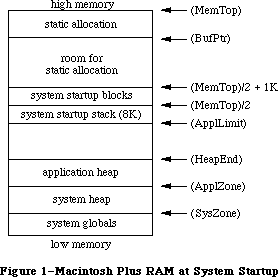 Figure 1–Macintosh Plus RAM at System Startup
The global variables, shown in parentheses, contain the addresses of the indicated areas.
The application heap limit (stored in the global variable ApplLimit) is set to 8K below the beginning of the boot stack to protect the stack.
Static allocation off the address contained in the global variable BufPtr is useful when a large amount of space is needed which will never be deallocated
(once space is allocated, it may not be deallocated unless no one has allocated space below). An 'INIT' resource may obtain permanent space by moving BufPtr down, but no further than the location of the boot blocks (MemTop/2 + 1K). (If it’s necessary to allocate space below MemTop/2 + 1K, contact Developer Technical Support for details.) It may also use the application zone for temporary heap memory.
Warning: An 'INIT' resource that wants to grow the system heap should be
aware that its associated resource map is open in the application
heap at the time.
To avoid their being deallocated when the application heap is initialized, vertical retrace tasks, AppleTalk listeners, and RAM-based drivers (and their storage) should be placed in the system heap or in statically allocated space.
Further Reference:
_______________________________________________________________________________
Resource Manager
Package Manager
Technical Note #14, The INIT 31 Mechanism
Technical Note #256, Stand-Alone Code, ad nauseam
Figure 1–Macintosh Plus RAM at System Startup
The global variables, shown in parentheses, contain the addresses of the indicated areas.
The application heap limit (stored in the global variable ApplLimit) is set to 8K below the beginning of the boot stack to protect the stack.
Static allocation off the address contained in the global variable BufPtr is useful when a large amount of space is needed which will never be deallocated
(once space is allocated, it may not be deallocated unless no one has allocated space below). An 'INIT' resource may obtain permanent space by moving BufPtr down, but no further than the location of the boot blocks (MemTop/2 + 1K). (If it’s necessary to allocate space below MemTop/2 + 1K, contact Developer Technical Support for details.) It may also use the application zone for temporary heap memory.
Warning: An 'INIT' resource that wants to grow the system heap should be
aware that its associated resource map is open in the application
heap at the time.
To avoid their being deallocated when the application heap is initialized, vertical retrace tasks, AppleTalk listeners, and RAM-based drivers (and their storage) should be placed in the system heap or in statically allocated space.
Further Reference:
_______________________________________________________________________________
Resource Manager
Package Manager
Technical Note #14, The INIT 31 Mechanism
Technical Note #256, Stand-Alone Code, ad nauseam
The Time Manager
_______________________________________________________________________________
THE TIME MANAGER
_______________________________________________________________________________
About This Chapter
About the Time Manager
Using the Time Manager
Time Manager Routines
Summary of the Time Manager
_______________________________________________________________________________
»ABOUT THIS CHAPTER
_______________________________________________________________________________
This chapter describes the Time Manager, the part of the Operating System that lets you schedule a routine to be executed after a given number of milliseconds have elapsed.
_______________________________________________________________________________
»ABOUT THE TIME MANAGER
_______________________________________________________________________________
The Time Manager provides the user with an asynchronous “wakeup” service with
1-millisecond accuracy; it can have any number of outstanding wakeup requests. The Time Manager is independent of clock speed or interrupts, and should be used in place of cycle-counting timing loops.
An application can add any number of tasks for the Time Manager to schedule. These tasks can perform any desired action so long as they don’t make any calls to the Memory Manager, directly or indirectly, and don’t depend on handles to unlocked blocks being valid. They must preserve all registers other than A0–A3 and D0–D3. If they use application globals, they must also ensure that register A5 contains the address of the boundary between the application globals and the application parameters; for details, see SetCurrentA5 and SetA5 in Macintosh Technical Note #208.
X-Ref: Technical Note #208
Note: To perform periodic actions that do allocate and release memory, you
can use the Desk Manager procedure SystemTask.
Information describing each Time Manager task is contained in the Time Manager queue; you need only supply a pointer to the routine to be executed. The Time Manager queue is a standard Macintosh queue, as described in the Operating System Utilities chapter. Each entry in the Time Manager queue has the following structure:
TYPE TMTask = RECORD
qLink: QElemPtr; {next queue entry}
qType: INTEGER; {queue type}
tmAddr: ProcPtr; {pointer to routine}
tmCount: INTEGER {reserved}
END;
_______________________________________________________________________________
»USING THE TIME MANAGER
_______________________________________________________________________________
The Time Manager is automatically initialized when the system starts up. Since the “sleep” time for a given task can be as small as 1 millisecond, you need to install a queue element in the Time Manager queue before actually making the wakeup request; to do this, call InsTime. To make the actual wakeup request, call PrimeTime. When you’re done, call RmvTime to remove the element from the queue.
_______________________________________________________________________________
»TIME MANAGER ROUTINES
_______________________________________________________________________________
PROCEDURE InsTime (tmTaskPtr: QElemPtr);
Trap macro _InsTime
On entry A0: tmTaskPtr (pointer)
On exit D0: result code (word)
InsTime adds the task specified by tmTaskPtr to the Time Manager queue. InsTime returns one of the result codes listed below.
Result codes noErr No error
PROCEDURE PrimeTime (tmTaskPtr,count: LONGINT);
Trap macro _PrimeTime
On entry A0: tmTaskPtr (pointer)
D0: count (long word)
On exit D0: result code ( word)
PrimeTime schedules the routine specified by tmTaskPtr to be executed after count milliseconds have elapsed. The queue element must already be inserted into the queue by a call to InsTime before making the PrimeTime call. The PrimeTime routine returns immediately, and the specified routine will be executed after count milliseconds have elapsed.
Result codes noErr No error
PROCEDURE RmvTime (tmTaskPtr: QElemPtr);
Trap macro _RmvTime
On entry A0: tmTaskPtr (pointer)
On exit D0: result code (word)
RmvTime removes the task specified by tmTaskPtr from the Time Manager queue. RmvTime returns one of the result codes listed below.
Result codes noErr No error
_______________________________________________________________________________
»SUMMARY OF THE TIME MANAGER
_______________________________________________________________________________
Data Types
TYPE
TMTask = RECORD
qLink: QElemPtr; {next queue entry}
qType: INTEGER; {queue type}
tmAddr: ProcPtr; {pointer to routine}
tmCount: INTEGER {reserved}
END;
_______________________________________________________________________________
Routines
PROCEDURE InsTime (tmTaskPtr: QElemPtr);
PROCEDURE RmvTime (tmTaskPtr: QElemPtr);
PROCEDURE PrimeTime (tmTaskPtr,count: LONGINT);
_______________________________________________________________________________
Assembly-Language Information
Routines
Trap macro On entry On exit
_InsTime A0: tmTaskPtr (ptr) D0: result code (word)
_RmvTime A0: tmTaskPtr (ptr) D0: result code (word)
_PrimeTime A0: tmTaskPtr (ptr) D0: result code (word)
D0: count (long)
Structure of Time Manager Queue Entry
qLink Pointer to next queue entry
qType Queue type (word)
tmAddr Pointer to task
tmCount Reserved (word)
Further Reference:
_______________________________________________________________________________
Desk Manager
OS Utilities
Technical Note #180, MultiFinder Miscellanea
Technical Note #208, Setting and Restoring A5
The Toolbox Event Manager
_______________________________________________________________________________
THE TOOLBOX EVENT MANAGER
_______________________________________________________________________________
About This Chapter
About the Toolbox Event Manager
Event Types
Priority of Events
Keyboard Events
The Apple Extended Keyboard
Reassigning Right Key Codes
Event Records
Event Code
Event Message
Modifier Flags
Event Masks
Using the Toolbox Event Manager
Responding to Mouse Events
Responding to Keyboard Events
Responding to Activate and Update Events
Responding to Disk-Inserted Events
Other Operations
Toolbox Event Manager Routines
Accessing Events
Reading the Mouse
Reading the Keyboard and Keypad
Miscellaneous Routines
The Journaling Mechanism
Writing Your Own Journaling Device Driver
Summary of the Toolbox Event Manager
_______________________________________________________________________________
»ABOUT THIS CHAPTER
_______________________________________________________________________________
This chapter describes the Event Manager, the part of the Toolbox that allows your application to monitor the user’s actions, such as those involving the mouse, keyboard, and keypad. The Event Manager is also used by other parts of the Toolbox; for instance, the Window Manager uses events to coordinate the ordering and display of windows on the screen.
There are actually two Event Managers: one in the Operating System and one in the Toolbox. The Toolbox Event Manager calls the Operating System Event Manager and serves as an interface between it and your application; it also adds some features that aren’t present at the Operating System level, such as the window management facilities mentioned above. This chapter describes the Toolbox Event Manager, which is the one your application will ordinarily deal with. All references to “the Event Manager” should be understood to refer to the Toolbox Event Manager. For information on the Operating System’s Event Manager, see the Operating System Event Manager chapter.
This chapter also describes four changes that enhance the ability of the Macintosh II and Macintosh SE to respond to keyboard events:
• Your application can now work with the Macintosh Plus, Macintosh II,
and Apple Extended Keyboards, all of which offer several new key
functions.
• The event message for keyboard events now distinguishes multiple
keyboards.
• A new modifier flag detects the state of the control key on the
Macintosh Plus and Apple Extended Keyboards.
• A new Toolbox routine, KeyTrans, helps your application convert key
codes into ASCII codes.
Note: Most of the constants and data types presented in this chapter are
actually defined in the Operating System Event Manager; they’re
explained here because they’re essential to understanding the Toolbox
Event Manager.
You should already be familiar with resources and with the basic concepts and structures behind QuickDraw.
_______________________________________________________________________________
»ABOUT THE TOOLBOX EVENT MANAGER
_______________________________________________________________________________
The Toolbox Event Manager is your application’s link to its user. Whenever the user presses the mouse button, types on the keyboard or keypad, or inserts a disk in a disk drive, your application is notified by means of an event. A typical Macintosh application program is event-driven: It decides what to do from moment to moment by asking the Event Manager for events and responding to them one by one in whatever way is appropriate.
Although the Event Manager’s primary purpose is to monitor the user’s actions and pass them to your application in an orderly way, it also serves as a convenient mechanism for sending signals from one part of your application to another. For instance, the Window Manager uses events to coordinate the ordering and display of windows as the user activates and deactivates them and moves them around on the screen. You can also define your own types of events and use them in any way you wish.
Most events waiting to be processed are kept in the event queue, where they’re stored (posted) by the Operating System Event Manager. The Toolbox Event Manager retrieves events from this queue for your application and also reports other events that aren’t kept in the queue, such as those related to windows. In general, events are collected from a variety of sources and reported to your application on demand, one at a time. Events aren’t necessarily reported in the order they occurred; some have a higher priority than others.
There are several different types of events. You can restrict some Event Manager routines to apply only to certain event types, in effect disabling the other types.
Other operations your application can perform with Event Manager routines include:
• directly reading the current state of the keyboard, keypad, and mouse
button
• monitoring the location of the mouse
• finding out how much time has elapsed since the system last started up
The Event Manager also provides a journaling mechanism, which enables events to be fed to the Event Manager from a source other than the user.
_______________________________________________________________________________
»EVENT TYPES
_______________________________________________________________________________
Events are of various types, depending on their origin and meaning. Some report actions by the user; others are generated by the Window Manager, by device drivers, or by your application itself for its own purposes. Some events are handled by the system before your application ever sees them; others are left for your application to handle in its own way.
The most important event types are those that record actions by the user:
• Mouse-down and mouse-up events occur when the user presses or releases
the mouse button.
• Key-down and key-up events occur when the user presses or releases a
key on the keyboard or keypad. Auto-key events are generated when the
user holds down a repeating key. Together, these three event types are
called keyboard events.
• Disk-inserted events occur when the user inserts a disk into a disk
drive or takes any other action that requires a volume to be mounted
(as described in the File Manager chapter). For example, a hard disk that
contains several volumes may also post a disk-inserted event.
Note: Mere movements of the mouse are not reported as events. If
necessary, your application can keep track of them by
periodically asking the Event Manager for the current location
of the mouse.
The following event types are generated by the Window Manager to coordinate the display of windows on the screen:
• Activate events are generated whenever an inactive window becomes
active or an active window becomes inactive. They generally occur in
pairs (that is, one window is deactivated and then another is activated).
• Update events occur when all or part of a window’s contents need to be
drawn or redrawn, usually as a result of the user’s opening, closing,
activating, or moving a window.
Another event type (device driver event) may be generated by device drivers in certain situations; for example, a driver might be set up to report an event when its transmission of data is interrupted. The chapters describing the individual drivers will tell you about any specific device driver events that may occur.
A network event may be generated by the AppleTalk Manager. It contains a handle to a parameter block; for details, see the File Manager chapter.
In addition, your application can define as many as four event types of its own and use them for any desired purpose.
Note: You place application-defined events in the event queue with the
Operating System Event Manager procedure PostEvent. See the Operating
System Event Manager chapter for details.
One final type of event is the null event, which is what the Event Manager returns if it has no other events to report.
_______________________________________________________________________________
»PRIORITY OF EVENTS
_______________________________________________________________________________
The event queue is a FIFO (first-in-first-out) list—that is, events are retrieved from the queue in the order they were originally posted. However, the way that various types of events are generated and detected causes some events to have higher priority than others. (Remember, not all events are kept in the event queue.) Furthermore, when you ask the Event Manager for an event, you can specify particular types that are of interest; doing so can cause some events to be passed over in favor of others that were actually posted later. The following discussion is limited to the event types you’ve specifically requested in your Event Manager call.
The Event Manager always returns the highest-priority event available of the requested types. The priority ranking is as follows:
1. activate (window becoming inactive before window becoming active)
2. mouse-down, mouse-up, key-down, key-up, disk-inserted, network, device
driver, application-defined (all in FIFO order)
3. auto-key
4. update (in front-to-back order of windows)
5. null
Activate events take priority over all others; they’re detected in a special way, and are never actually placed in the event queue. The Event Manager checks for pending activate events before looking in the event queue, so it will always return such an event if one is available. Because of the special way activate events are detected, there can never be more than two such events pending at the same time; at most there will be one for a window becoming inactive followed by another for a window becoming active.
Category 2 includes most of the event types. Within this category, events are retrieved from the queue in the order they were posted.
If no event is available in categories 1 and 2, the Event Manager reports an auto-key event if the appropriate conditions hold for one. (These conditions are described in detail in the next section.)
Next in priority are update events. Like activate events, these are not placed in the event queue, but are detected in another way. If no higher-priority event is available, the Event Manager checks for windows whose contents need to be drawn. If it finds one, it returns an update event for that window. Windows are checked in the order in which they’re displayed on the screen, from front to back, so if two or more windows need to be updated, an update event will be returned for the frontmost such window.
Finally, if no other event is available, the Event Manager returns a null event.
Note: The event queue normally has a capacity of 20 events. If the queue
should become full, the Operating System Event Manager will begin
discarding old events to make room for new ones as they’re posted.
The events discarded are always the oldest ones in the queue. The
capacity of the event queue is determined by the system startup
information stored on a volume; for more information, see the
section “Data Organization on Volumes” in the File Manager chapter.
_______________________________________________________________________________
»KEYBOARD EVENTS
_______________________________________________________________________________
The character keys on the Macintosh keyboard and numeric keypad generate key-down and key-up events when pressed and released; this includes all keys except Shift, Caps Lock, Command, and Option, which are called modifier keys.
(Modifier keys are treated specially, as described below, and generate no keyboard events of their own.) In addition, an auto-key event is posted whenever all of the following conditions apply:
• Auto-key events haven’t been disabled. (This is discussed further under
“Event Masks” below.)
• No higher-priority event is available.
• The user is currently holding down a character key.
• The appropriate time interval (see below) has elapsed since the last
key-down or auto-key event.
Two different time intervals are associated with auto-key events. The first auto-key event is generated after a certain initial delay has elapsed since the original key-down event (that is, since the key was originally pressed); this is called the auto-key threshold. Subsequent auto-key events are then generated each time a certain repeat interval has elapsed since the last such event; this is called the auto-key rate. The default values are 16 ticks (sixtieths of a second) for the auto-key threshold and four ticks for the auto-key rate. The user can change these values with the Control Panel desk accessory, by adjusting the keyboard touch and the rate of repeating keys.
Assembly-language note: The current values for the auto-key threshold and
rate are stored in the global variables KeyThresh
and KeyRepThresh, respectively.
When the user presses, holds down, or releases a character key, the character generated by that key is identified internally with a character code. Character codes are given in the extended version of ASCII (the American Standard Code for Information Interchange) used by the Macintosh. A table showing the character codes for the standard Macintosh character set appears in Figure 1. All character codes are given in hexadecimal in this table. The first digit of a character’s hexadecimal value is shown at the top of the table, the second down the left side. For example, character code $47 stands for “G”, which appears in the table at the intersection of column 4 and row 7.
Macintosh, the owner’s guide, describes the method of generating the printing characters (codes $20 through $D8) shown in Figure 1. Notice that in addition to the regular space character ($20) there’s a nonbreaking space ($CA), which is generated by pressing the space bar with the Option key down.
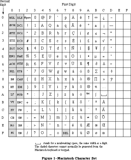 Figure 1–Macintosh Character Set
Nonprinting or “control” characters ($00 through $1F, as well as $7F) are identified in the table by their traditional ASCII abbreviations; those that are shaded have no special meaning on the Macintosh and cannot normally be generated from the Macintosh keyboard or keypad. Those that can be generated are listed below along with the method of generating them:
Code Abbreviation Key
$03 ETX Enter key on keyboard or keypad
$08 BS Backspace key on keyboard
$09 HT Tab key on keyboard
$0D CR Return key on keyboard
$1B ESC Clear key on keypad
$1C FS Left arrow key on keypad
$1D GS Right arrow key on keypad
$1E RS Up arrow key on keypad
$1F US Down arrow key on keypad
The association between characters and keys on the keyboard or the keypad is defined by a keyboard configuration, which is a resource stored in a resource file. The particular character that’s generated by a character key depends on three things:
• the character key being pressed
• which, if any, of the modifier keys were held down when the character
key was pressed
• the keyboard configuration currently in effect
The modifier keys, instead of generating keyboard events themselves, modify the meaning of the character keys by changing the character codes that those keys generate. For example, under the standard U.S. keyboard configuration, the “C” key generates any of the following, depending on which modifier keys are held down:
Key(s) pressed Character generated
“C” by itself Lowercase c
“C” with Shift or Caps Lock down Capital C
“C” with Option down Lowercase c with a cedilla(ç),
used in foreign languages
“C” with Option and Shift down, or Capital C with a cedilla (Ç)
with Option and Caps Lock down
The state of each of the modifier keys is also reported in a field of the event record (see next section), where your application can examine it directly.
Note: As described in the owner’s guide, some accented characters are
generated by pressing Option along with another key for the accent,
and then typing the character to be accented. In these cases, a
single key-down event occurs for the accented character; there’s no
event corresponding to the typing of the accent.
Under the standard keyboard configuration, only the Shift, Caps Lock, and Option keys actually modify the character code generated by a character key on the keyboard; the Command key has no effect on the character code generated. Similarly, character codes for the keypad are affected only by the Shift key. To find out whether the Command key was down at the time of an event (or Caps Lock or Option in the case of one generated from the keypad), you have to examine the event record field containing the state of the modifier keys.
_______________________________________________________________________________
»The Apple Extended Keyboard
Apple now offers the Extended Keyboard as an option. Besides all the key functions of the present U.S. keyboard and keypad, it contains the following new ones:
• Fifteen general Function keys, labeled F1 through F15. Applications
that use Undo, Cut, Copy, and Paste should assign keys F1 through F4
to these operations. Keys F5 through F15 are intended to be defined
by the user, not by the application.
• A Control key. This is included for compatibility with applications
requiring a Control key, which the Macintosh might access through
communication with another operating system. It should not be used
by new Macintosh applications. Pressing it sets bit 12 of the modifiers
field of the event record for keyboard events.
• A Help key. This key is available to the user to request help or
instructions from your application.
• A Forward Delete (Fwd Del) key. Pressing this key performs a forward
text delete: the character immediately to the right of the insertion
point is removed and all subsequent characters are shifted left one
place. When the Fwd Del key is held down, the effect is that the
insertion point remains stationary while everything ahead of it is
“vacuumed” away. If it is pressed while there is a current selection,
it removes the selected text.
• A Home key. Pressing the Home key is equivalent to moving the vertical
scroll box to the top and the horizontal scroll box to the far left.
It has no effect on the current insertion point or on any selected
material.
• An End key. Pressing the End key is equivalent to moving the vertical
scroll box to the bottom and the horizontal scroll box to the far right.
It has no effect on the current insertion point or on any selected
material.
• A Page Up key. Pressing the Page Up key is equivalent to clicking in
the page-up region of the vertical scroll bar of the active window.
It has no effect on the current insertion point or on any selected
material.
• A Page Down key. Pressing the Page Down key is equivalent to clicking
in the page-down region of the vertical scroll bar of the active window.
It has no effect on the current insertion point or on any selected
material.
• Duplicated Shift, Option, and Control Keys. On the Apple Extended
Keyboard, the Shift, Option, and Control keys occur both to the right
and to the left of the space bar. Normally they have the same key
codes. However, it is possible to send the keyboard a command that
changes the key codes for the keys on the right side. This possibility
is discussed under “Reassigning Right Key Codes”, below.
»Reassigning Right Key Codes
It is possible to reassign the key codes for the Shift, Option, and Control keys on the right side of the Apple Extended keyboard to the following:
Right key Raw key code Virtual key code
Shift $7B 3C
Option $7C 3D
Control $7D 3E
Changing these key codes requires changing the value of the Device Handler ID field in the Apple Extended Keyboard’s register 3 from 2 to 3. The Device Handler ID is described in the Apple Desktop Bus chapter.
Warning: This capability is included for compatibility with certain existing
operating systems that distinguish the right and left keys. Its use
by new applications violates the Apple user interface guidelines and
is strongly discouraged.
_______________________________________________________________________________
»EVENT RECORDS
_______________________________________________________________________________
Every event is represented internally by an event record containing all pertinent information about that event. The event record includes the following information:
• the type of event
• the time the event was posted (in ticks since system startup)
• the location of the mouse at the time the event was posted (in global
coordinates)
• the state of the mouse button and modifier keys at the time the event
was posted
• any additional information required for a particular type of event, such
as which key the user pressed or which window is being activated
Every event has an event record containing this information—even null events.
Event records are defined as follows:
TYPE EventRecord = RECORD
what: INTEGER; {event code}
message: LONGINT; {event message}
when: LONGINT; {ticks since startup}
where: Point; {mouse location}
modifiers: INTEGER {modifier flags}
END;
The when field contains the number of ticks since the system last started up, and the where field gives the location of the mouse, in global coordinates, at the time the event was posted. The other three fields are described below.
_______________________________________________________________________________
»Event Code
The what field of an event record contains an event code identifying the type of the event. The event codes are available as predefined constants:
CONST nullEvent = 0; {null}
mouseDown = 1; {mouse-down}
mouseUp = 2; {mouse-up}
keyDown = 3; {key-down}
keyUp = 4; {key-up}
autoKey = 5; {auto-key}
updateEvt = 6; {update}
diskEvt = 7; {disk-inserted}
activateEvt = 8; {activate}
networkEvt = 10; {network}
driverEvt = 11; {device driver}
app1Evt = 12; {application-defined}
app2Evt = 13; {application-defined}
app3Evt = 14; {application-defined}
app4Evt = 15; {application-defined}
_______________________________________________________________________________
»Event Message
The message field of an event record contains the event message, which conveys additional important information about the event. The nature of this information depends on the event type, as summarized in the following table and described below.
Event type Event message
Keyboard Character code, key code, and ADB address field
Activate, update Pointer to window
Disk-inserted Drive number in low-order word, File Manager
result code in high-order word
Mouse-down, Undefined
mouse-up, null
Network Handle to parameter block
Device driver See chapter describing driver
Application-defined Whatever you wish
For keyboard events, the low-order byte of the low-order word of the event message contains the ASCII character code generated by the key or combination of keys that was pressed or released; usually this is all you’ll need. However, as described in the Apple Desktop Bus chapter, the Macintosh II and SE can be connected to multiple keyboards. To identify the origin of keyboard events, the keyboard event message contains a new ADB address field. It now has the structure shown in Figure 2.
Warning: The high byte of the event message for keyboard events is reserved
for future use, and is not presently guaranteed to be zero.
The event message for non-keyboard events remains the same as described above.
Figure 1–Macintosh Character Set
Nonprinting or “control” characters ($00 through $1F, as well as $7F) are identified in the table by their traditional ASCII abbreviations; those that are shaded have no special meaning on the Macintosh and cannot normally be generated from the Macintosh keyboard or keypad. Those that can be generated are listed below along with the method of generating them:
Code Abbreviation Key
$03 ETX Enter key on keyboard or keypad
$08 BS Backspace key on keyboard
$09 HT Tab key on keyboard
$0D CR Return key on keyboard
$1B ESC Clear key on keypad
$1C FS Left arrow key on keypad
$1D GS Right arrow key on keypad
$1E RS Up arrow key on keypad
$1F US Down arrow key on keypad
The association between characters and keys on the keyboard or the keypad is defined by a keyboard configuration, which is a resource stored in a resource file. The particular character that’s generated by a character key depends on three things:
• the character key being pressed
• which, if any, of the modifier keys were held down when the character
key was pressed
• the keyboard configuration currently in effect
The modifier keys, instead of generating keyboard events themselves, modify the meaning of the character keys by changing the character codes that those keys generate. For example, under the standard U.S. keyboard configuration, the “C” key generates any of the following, depending on which modifier keys are held down:
Key(s) pressed Character generated
“C” by itself Lowercase c
“C” with Shift or Caps Lock down Capital C
“C” with Option down Lowercase c with a cedilla(ç),
used in foreign languages
“C” with Option and Shift down, or Capital C with a cedilla (Ç)
with Option and Caps Lock down
The state of each of the modifier keys is also reported in a field of the event record (see next section), where your application can examine it directly.
Note: As described in the owner’s guide, some accented characters are
generated by pressing Option along with another key for the accent,
and then typing the character to be accented. In these cases, a
single key-down event occurs for the accented character; there’s no
event corresponding to the typing of the accent.
Under the standard keyboard configuration, only the Shift, Caps Lock, and Option keys actually modify the character code generated by a character key on the keyboard; the Command key has no effect on the character code generated. Similarly, character codes for the keypad are affected only by the Shift key. To find out whether the Command key was down at the time of an event (or Caps Lock or Option in the case of one generated from the keypad), you have to examine the event record field containing the state of the modifier keys.
_______________________________________________________________________________
»The Apple Extended Keyboard
Apple now offers the Extended Keyboard as an option. Besides all the key functions of the present U.S. keyboard and keypad, it contains the following new ones:
• Fifteen general Function keys, labeled F1 through F15. Applications
that use Undo, Cut, Copy, and Paste should assign keys F1 through F4
to these operations. Keys F5 through F15 are intended to be defined
by the user, not by the application.
• A Control key. This is included for compatibility with applications
requiring a Control key, which the Macintosh might access through
communication with another operating system. It should not be used
by new Macintosh applications. Pressing it sets bit 12 of the modifiers
field of the event record for keyboard events.
• A Help key. This key is available to the user to request help or
instructions from your application.
• A Forward Delete (Fwd Del) key. Pressing this key performs a forward
text delete: the character immediately to the right of the insertion
point is removed and all subsequent characters are shifted left one
place. When the Fwd Del key is held down, the effect is that the
insertion point remains stationary while everything ahead of it is
“vacuumed” away. If it is pressed while there is a current selection,
it removes the selected text.
• A Home key. Pressing the Home key is equivalent to moving the vertical
scroll box to the top and the horizontal scroll box to the far left.
It has no effect on the current insertion point or on any selected
material.
• An End key. Pressing the End key is equivalent to moving the vertical
scroll box to the bottom and the horizontal scroll box to the far right.
It has no effect on the current insertion point or on any selected
material.
• A Page Up key. Pressing the Page Up key is equivalent to clicking in
the page-up region of the vertical scroll bar of the active window.
It has no effect on the current insertion point or on any selected
material.
• A Page Down key. Pressing the Page Down key is equivalent to clicking
in the page-down region of the vertical scroll bar of the active window.
It has no effect on the current insertion point or on any selected
material.
• Duplicated Shift, Option, and Control Keys. On the Apple Extended
Keyboard, the Shift, Option, and Control keys occur both to the right
and to the left of the space bar. Normally they have the same key
codes. However, it is possible to send the keyboard a command that
changes the key codes for the keys on the right side. This possibility
is discussed under “Reassigning Right Key Codes”, below.
»Reassigning Right Key Codes
It is possible to reassign the key codes for the Shift, Option, and Control keys on the right side of the Apple Extended keyboard to the following:
Right key Raw key code Virtual key code
Shift $7B 3C
Option $7C 3D
Control $7D 3E
Changing these key codes requires changing the value of the Device Handler ID field in the Apple Extended Keyboard’s register 3 from 2 to 3. The Device Handler ID is described in the Apple Desktop Bus chapter.
Warning: This capability is included for compatibility with certain existing
operating systems that distinguish the right and left keys. Its use
by new applications violates the Apple user interface guidelines and
is strongly discouraged.
_______________________________________________________________________________
»EVENT RECORDS
_______________________________________________________________________________
Every event is represented internally by an event record containing all pertinent information about that event. The event record includes the following information:
• the type of event
• the time the event was posted (in ticks since system startup)
• the location of the mouse at the time the event was posted (in global
coordinates)
• the state of the mouse button and modifier keys at the time the event
was posted
• any additional information required for a particular type of event, such
as which key the user pressed or which window is being activated
Every event has an event record containing this information—even null events.
Event records are defined as follows:
TYPE EventRecord = RECORD
what: INTEGER; {event code}
message: LONGINT; {event message}
when: LONGINT; {ticks since startup}
where: Point; {mouse location}
modifiers: INTEGER {modifier flags}
END;
The when field contains the number of ticks since the system last started up, and the where field gives the location of the mouse, in global coordinates, at the time the event was posted. The other three fields are described below.
_______________________________________________________________________________
»Event Code
The what field of an event record contains an event code identifying the type of the event. The event codes are available as predefined constants:
CONST nullEvent = 0; {null}
mouseDown = 1; {mouse-down}
mouseUp = 2; {mouse-up}
keyDown = 3; {key-down}
keyUp = 4; {key-up}
autoKey = 5; {auto-key}
updateEvt = 6; {update}
diskEvt = 7; {disk-inserted}
activateEvt = 8; {activate}
networkEvt = 10; {network}
driverEvt = 11; {device driver}
app1Evt = 12; {application-defined}
app2Evt = 13; {application-defined}
app3Evt = 14; {application-defined}
app4Evt = 15; {application-defined}
_______________________________________________________________________________
»Event Message
The message field of an event record contains the event message, which conveys additional important information about the event. The nature of this information depends on the event type, as summarized in the following table and described below.
Event type Event message
Keyboard Character code, key code, and ADB address field
Activate, update Pointer to window
Disk-inserted Drive number in low-order word, File Manager
result code in high-order word
Mouse-down, Undefined
mouse-up, null
Network Handle to parameter block
Device driver See chapter describing driver
Application-defined Whatever you wish
For keyboard events, the low-order byte of the low-order word of the event message contains the ASCII character code generated by the key or combination of keys that was pressed or released; usually this is all you’ll need. However, as described in the Apple Desktop Bus chapter, the Macintosh II and SE can be connected to multiple keyboards. To identify the origin of keyboard events, the keyboard event message contains a new ADB address field. It now has the structure shown in Figure 2.
Warning: The high byte of the event message for keyboard events is reserved
for future use, and is not presently guaranteed to be zero.
The event message for non-keyboard events remains the same as described above.
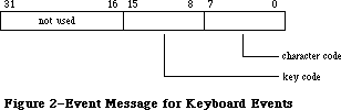 Figure 2–Event Message for Keyboard Events
The key code in the event message for a keyboard event represents the character key that was pressed or released; this value is always the same for any given character key, regardless of the modifier keys pressed along with it. Key codes are useful in special cases—in a music generator, for example—where you want to treat the keyboard as a set of keys unrelated to characters. Figure 3 gives the key codes for all the keys on the keyboard and keypad. (Key codes are shown for modifier keys here because they’re meaningful in other contexts, as explained later.) Both the U.S. and international keyboards are shown; in some cases the codes are quite different (for example, space and Enter are reversed).
Three keyboards are now available as standard equipment with Macintosh computers sold in the U.S. They are
• The Macintosh Plus Keyboard, which includes cursor control keys and an
integral keypad. Its layout and key coding is shown in Figure 4.
• The Macintosh II Keyboard, also shipped with the Macintosh SE, which
adds Esc (Escape) and Control keys and is connected to the Apple Desktop
Bus. Its layout and key coding is shown in Figure 5.
• The Apple Extended Keyboard, which the user may connect to the Apple
Desktop Bus of any Macintosh II or Macintosh SE computer. Its layout
and key coding is shown in Figure 6.
These figures show the virtual key codes for each key; they are the key codes that actually appear in keyboard events. In the case of the Macintosh II and Apple Extended Keyboards, however, the hardware produces raw key codes, which may be different. Raw key codes are translated to virtual key codes by the
'KMAP' resource in the System Folder. By modifying the 'KMAP' resource you can change the key codes for any keys. Similarly, you can change the ASCII codes corresponding to specific key codes by modifying the 'KCHR' resource in the System Folder. The 'KMAP' and 'KCHR' resources are described in the Resource Manager chapter.
With both the Macintosh II and the Apple Extended keyboards, the standard 'KMAP' resource supplied in the system folder reassigns the following raw key codes to different virtual key codes:
Key Raw key code Virtual key code
Control 36 3B
Left cursor 3B 7B
Right cursor 3C 7C
Down cursor 3D 7D
Up cursor 3E 7E
The standard 'KMAP' resource leaves all other raw key codes and virtual key codes the same.
With the Apple Extended Keyboard, the virtual key codes for three more keys may be easily reassigned, as described above under “Reassigning Right Key Codes”.
The following predefined constants are available to help you access the character code and key code:
CONST charCodeMask = $000000FF; {character code}
keyCodeMask = $0000FF00; {key code}
Figure 2–Event Message for Keyboard Events
The key code in the event message for a keyboard event represents the character key that was pressed or released; this value is always the same for any given character key, regardless of the modifier keys pressed along with it. Key codes are useful in special cases—in a music generator, for example—where you want to treat the keyboard as a set of keys unrelated to characters. Figure 3 gives the key codes for all the keys on the keyboard and keypad. (Key codes are shown for modifier keys here because they’re meaningful in other contexts, as explained later.) Both the U.S. and international keyboards are shown; in some cases the codes are quite different (for example, space and Enter are reversed).
Three keyboards are now available as standard equipment with Macintosh computers sold in the U.S. They are
• The Macintosh Plus Keyboard, which includes cursor control keys and an
integral keypad. Its layout and key coding is shown in Figure 4.
• The Macintosh II Keyboard, also shipped with the Macintosh SE, which
adds Esc (Escape) and Control keys and is connected to the Apple Desktop
Bus. Its layout and key coding is shown in Figure 5.
• The Apple Extended Keyboard, which the user may connect to the Apple
Desktop Bus of any Macintosh II or Macintosh SE computer. Its layout
and key coding is shown in Figure 6.
These figures show the virtual key codes for each key; they are the key codes that actually appear in keyboard events. In the case of the Macintosh II and Apple Extended Keyboards, however, the hardware produces raw key codes, which may be different. Raw key codes are translated to virtual key codes by the
'KMAP' resource in the System Folder. By modifying the 'KMAP' resource you can change the key codes for any keys. Similarly, you can change the ASCII codes corresponding to specific key codes by modifying the 'KCHR' resource in the System Folder. The 'KMAP' and 'KCHR' resources are described in the Resource Manager chapter.
With both the Macintosh II and the Apple Extended keyboards, the standard 'KMAP' resource supplied in the system folder reassigns the following raw key codes to different virtual key codes:
Key Raw key code Virtual key code
Control 36 3B
Left cursor 3B 7B
Right cursor 3C 7C
Down cursor 3D 7D
Up cursor 3E 7E
The standard 'KMAP' resource leaves all other raw key codes and virtual key codes the same.
With the Apple Extended Keyboard, the virtual key codes for three more keys may be easily reassigned, as described above under “Reassigning Right Key Codes”.
The following predefined constants are available to help you access the character code and key code:
CONST charCodeMask = $000000FF; {character code}
keyCodeMask = $0000FF00; {key code}
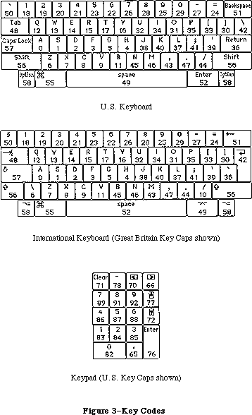 Figure 3–Key Codes
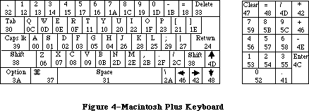 Figure 4–Macintosh Plus Keyboard
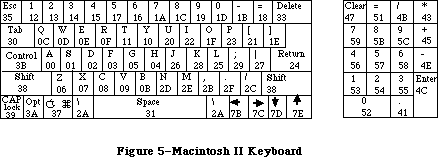 Figure 5–Macintosh II Keyboard
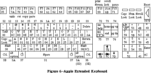 Figure 6–Apple Extended Keyboard
Note: You can use the Toolbox Utility function BitAnd with these constants;
for instance, to access the character code, use
charCode := BitAnd(my Event.message,charCodeMask)
For activate and update events, the event message is a pointer to the window affected. (If the event is an activate event, additional important information about the event can be found in the modifiers field of the event record, as described below.)
For disk-inserted events, the low-order word of the event message contains the drive number of the disk drive into which the disk was inserted: 1 for the Macintosh’s built-in drive, and 2 for the external drive, if any. Numbers greater than 2 denote additional disk drives connected to the Macintosh. By the time your application receives a disk-inserted event, the system will already have attempted to mount the volume on the disk by calling the File Manager function MountVol; the high-order word of the event message will contain the result code returned by MountVol.
For mouse-down, mouse-up, and null events, the event message is undefined and should be ignored. The event message for a network event contains a handle to a parameter block, as described in the AppleTalk Manager chapter. For device driver events, the contents of the event message depend on the situation under which the event was generated; the chapters describing those situations will give the details. Finally, you can use the event message however you wish for application-defined event types.
_______________________________________________________________________________
»Modifier Flags
As mentioned above, the modifiers field of an event record contains further information about activate events and the state of the modifier keys and mouse button at the time the event was posted (see Figure 7). You might look at this field to find out, for instance, whether the Command key was down when a mouse-down event was posted (which in many applications affects the way objects are selected) or when a key-down event was posted (which could mean the user is choosing a menu item by typing its keyboard equivalent).
Figure 6–Apple Extended Keyboard
Note: You can use the Toolbox Utility function BitAnd with these constants;
for instance, to access the character code, use
charCode := BitAnd(my Event.message,charCodeMask)
For activate and update events, the event message is a pointer to the window affected. (If the event is an activate event, additional important information about the event can be found in the modifiers field of the event record, as described below.)
For disk-inserted events, the low-order word of the event message contains the drive number of the disk drive into which the disk was inserted: 1 for the Macintosh’s built-in drive, and 2 for the external drive, if any. Numbers greater than 2 denote additional disk drives connected to the Macintosh. By the time your application receives a disk-inserted event, the system will already have attempted to mount the volume on the disk by calling the File Manager function MountVol; the high-order word of the event message will contain the result code returned by MountVol.
For mouse-down, mouse-up, and null events, the event message is undefined and should be ignored. The event message for a network event contains a handle to a parameter block, as described in the AppleTalk Manager chapter. For device driver events, the contents of the event message depend on the situation under which the event was generated; the chapters describing those situations will give the details. Finally, you can use the event message however you wish for application-defined event types.
_______________________________________________________________________________
»Modifier Flags
As mentioned above, the modifiers field of an event record contains further information about activate events and the state of the modifier keys and mouse button at the time the event was posted (see Figure 7). You might look at this field to find out, for instance, whether the Command key was down when a mouse-down event was posted (which in many applications affects the way objects are selected) or when a key-down event was posted (which could mean the user is choosing a menu item by typing its keyboard equivalent).
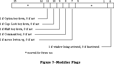 Figure 7–Modifier Flags
The following predefined constants are useful as masks for reading the flags in the modifiers field:
CONST activeFlag = 1; {set if window being activated}
btnState = 128; {set if mouse button up}
cmdKey = 256; {set if Command key down}
shiftKey = 512; {set if Shift key down}
alphaLock = 1024; {set if Caps Lock key down}
optionKey = 2048; {set if Option key down}
ControlKey = 4096; {set if Control key down}
The activeFlag bit gives further information about activate events; it’s set if the window pointed to by the event message is being activated, or 0 if the window is being deactivated. The remaining bits indicate the state of the mouse button and modifier keys. Notice that the btnState bit is set if the mouse button is up, whereas the bits for the four modifier keys are set if their corresponding keys are down.
_______________________________________________________________________________
»EVENT MASKS
_______________________________________________________________________________
Some of the Event Manager routines can be restricted to operate on a specific event type or group of types; in other words, the specified event types are enabled while all others are disabled. For instance, instead of just requesting the next available event, you can specifically ask for the next keyboard event.
You specify which event types a particular Event Manager call applies to by supplying an event mask as a parameter. This is an integer in which there’s one bit position for each event type, as shown in Figure 8. The bit position representing a given type corresponds to the event code for that type—for example, update events (event code 6) are specified by bit 6 of the mask. A 1 in bit 6 means that this Event Manager call applies to update events; a 0 means that it doesn’t.
Figure 7–Modifier Flags
The following predefined constants are useful as masks for reading the flags in the modifiers field:
CONST activeFlag = 1; {set if window being activated}
btnState = 128; {set if mouse button up}
cmdKey = 256; {set if Command key down}
shiftKey = 512; {set if Shift key down}
alphaLock = 1024; {set if Caps Lock key down}
optionKey = 2048; {set if Option key down}
ControlKey = 4096; {set if Control key down}
The activeFlag bit gives further information about activate events; it’s set if the window pointed to by the event message is being activated, or 0 if the window is being deactivated. The remaining bits indicate the state of the mouse button and modifier keys. Notice that the btnState bit is set if the mouse button is up, whereas the bits for the four modifier keys are set if their corresponding keys are down.
_______________________________________________________________________________
»EVENT MASKS
_______________________________________________________________________________
Some of the Event Manager routines can be restricted to operate on a specific event type or group of types; in other words, the specified event types are enabled while all others are disabled. For instance, instead of just requesting the next available event, you can specifically ask for the next keyboard event.
You specify which event types a particular Event Manager call applies to by supplying an event mask as a parameter. This is an integer in which there’s one bit position for each event type, as shown in Figure 8. The bit position representing a given type corresponds to the event code for that type—for example, update events (event code 6) are specified by bit 6 of the mask. A 1 in bit 6 means that this Event Manager call applies to update events; a 0 means that it doesn’t.
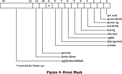 Figure 8–Event Mask
Masks for each individual event type are available as predefined constants:
CONST mDownMask = 2; {mouse-down}
mUpMask = 4; {mouse-up}
keyDownMask = 8; {key-down}
keyUpMask = 16; {key-up}
autoKeyMask = 32; {auto-key}
updateMask = 64; {update}
diskMask = 128; {disk-inserted}
activMask = 256; {activate}
networkMask = 1024; {network}
driverMask = 2048; {device driver}
app1Mask = 4096; {application-defined}
app2Mask = 8192; {application-defined}
app3Mask = 16384; {application-defined}
app4Mask = -32768; {application-defined}
Note: Null events can’t be disabled; a null event will always be reported
when none of the enabled types of events are available.
The following predefined mask designates all event types:
CONST everyEvent = -1; {all event types}
You can form any mask you need by adding or subtracting these mask constants. For example, to specify every keyboard event, use
keyDownMask + keyUpMask + autoKeyMask
For every event except an update, use
everyEvent - updateMask
Note: It’s recommended that you always use the event mask everyEvent unless
there’s a specific reason not to.
There’s also a global system event mask that controls which event types get posted into the event queue. Only event types corresponding to bits set in the system event mask are posted; all others are ignored. When the system starts up, the system event mask is set to post all except key-up event—that is, it’s initialized to
everyEvent - keyUpMask
Note: Key-up events are meaningless for most applications. Your application
will usually want to ignore them; if not, it can set the system event
mask with the Operating System Event Manager procedure SetEventMask.
_______________________________________________________________________________
»USING THE TOOLBOX EVENT MANAGER
_______________________________________________________________________________
Before using the Event Manager, you should initialize the Window Manager by calling its procedure InitWindows; parts of the Event Manager rely on the Window Manager’s data structures and will not work properly unless those structures have been properly initialized. Initializing the Window Manager requires you to have initialized QuickDraw and the Font Manager.
Assembly-language note: If you want to use events but not windows, set the
global variable WindowList (a long word) to 0 instead
of calling InitWindows.
It’s also usually a good idea to issue the Operating System Event Manager call FlushEvents(everyEvent,0) to empty the event queue of any stray events left over from before your application started up (such as keystrokes typed to the Finder). See the Operating System Event Manager chapter for a description of FlushEvents.
Most Macintosh application programs are event-driven. Such prorams have a main loop that repeatedly calls GetNextEvent to retrieve the next available event, and then uses a CASE statement to take whatever action is appropriate for each type of event; some typical responses to commonly occurring events are described below. Your program is expected to respond only to those events that are directly related to its own operations. After calling GetNextEvent, you should test its Boolean result to find out whether your application needs to respond to the event: TRUE means the event may be of interest to your application; FALSE usually means it will not be of interest.
In some cases, you may simply want to look at a pending event while leaving it available for subsequent retrieval by GetNextEvent. You can do this with the EventAvail function.
_______________________________________________________________________________
»Responding to Mouse Events
On receiving a mouse-down event, your application should first call the Window Manager function FindWindow to find out where on the screen the mouse button was pressed, and then respond in whatever way is appropriate. Depending on the part of the screen in which the button was pressed, this may involve calls to Toolbox routines such as the Menu Manager function
MenuSelect, the Desk Manager procedure SystemClick, the Window Manager routines SelectWindow, DragWindow, GrowWindow, and TrackGoAway, and the Control Manager routines FindControl, TrackControl, and DragControl. See the relevant chapters for details.
If your application attaches some special significance to pressing a modifier key along with the mouse button, you can discover the state of that modifier key while the mouse button is down by examining the appropriate flag in the modifiers field.
If you’re using the TextEdit part of the Toolbox to handle text editing, mouse double-clicks will work automatically as a means of selecting a word; to respond to double-clicks in any other context, however, you’ll have to detect them yourself. You can do so by comparing the time and location of a mouse-up event with those of the immediately following mouse-down event. You should assume a double-click has occurred if both of the following are true:
• The times of the mouse-up event and the mouse-down event differ by a
number of ticks less than or equal to the value returned by the Event
Manager function GetDblTime.
• The locations of the two mouse-down events separated by the mouse-up
event are sufficiently close to each other. Exactly what this means
depends on the particular application. For instance, in a word-processing
application, you might consider the two locations essentially the same
if they fall on the same character, whereas in a graphics application
you might consider them essentially the same if the sum of the horizontal
and vertical changes in position is no more than five pixels.
Mouse-up events may be significant in other ways; for example, they might signal the end of dragging to select more than one object. Most simple applications, however, will ignore mouse-up events.
_______________________________________________________________________________
»Responding to Keyboard Events
For a key-down event, you should first check the modifiers field to see whether the character was typed with the Command key held down; if so, the user may have been choosing a menu item by typing its keyboard equivalent. To find out, pass the character that was typed to the Menu Manager function MenuKey. (See the Menu Manager chapter for details.)
If the key-down event was not a menu command, you should then respond to the event in whatever way is appropriate for your application. For example, if one of your windows is active, you might want to insert the typed character into the active document; if none of your windows is active, you might want to ignore the event.
Usually your application can handle auto-key events the same as key-down events. You may, however, want to ignore auto-key events that invoke commands that shouldn’t be continually repeated.
Note: Remember that most applications will want to ignore key-up events;
with the standard system event mask you won’t get any.
If you wish to periodically inspect the state of the keyboard or keypad—say, while the mouse button is being held down—use the procedure GetKeys; this procedure is also the only way to tell whether a modifier key is being pressed alone.
_______________________________________________________________________________
»Responding to Activate and Update Events
When your application receives an activate event for one of its own windows, the Window Manager will already have done all of the normal “housekeeping” associated with the event, such as highlighting or unhighlighting the window. You can then take any further action that your application may require, such as showing or hiding a scroll bar or highlighting or unhighlighting a selection.
On receiving an update event for one of its own windows, your application should usually call the Window Manager procedure BeginUpdate, draw the window’s contents, and then call EndUpdate. See the Window Manager chapter for important additional information on activate and update events.
_______________________________________________________________________________
»Responding to Disk-Inserted Events
Most applications will use the Standard File Package, which responds to disk-inserted events for you during standard file saving and opening; you’ll usually want to ignore any other disk-inserted events, such as the user’s inserting a disk when not expected. If, however, you do want to respond to other disk-inserted events, or if you plan not to use the Standard File Package, then
you’ll have to handle such events yourself.
When you receive a disk-inserted event, the system will already have attempted to mount the volume on the disk by calling the File Manager function MountVol. You should examine the result code returned by the File Manager in the high-order word of the event message. If the result code indicates that the attempt to mount the volume was unsuccessful, you might want to take some special action, such as calling the Disk Initialization Package function DIBadMount. See the File Manager and Disk Initialization Package chapters for further details.
_______________________________________________________________________________
»Other Operations
In addition to receiving the user’s mouse and keyboard actions in the form of events, you can directly read the keyboard (and keypad), mouse location, and state of the mouse button by calling GetKeys, GetMouse, and Button, respectively. A new routine in the 256K ROM lets your application convert key codes to ASCII values as determined by a 'KCHR' resource. The 'KCHR' resource type is discussed in the Resource Manager chapter. To follow the mouse when the user moves it with the button down, use StillDown or WaitMouseUp.
The function TickCount returns the number of ticks since the last system startup; you might, for example, compare this value to the when field of an event record to discover the delay since that event was posted.
Finally, the function GetCaretTime returns the number of ticks between blinks of the “caret” (usually a vertical bar) marking the insertion point in editable text. You should call GetCaretTime if you aren’t using TextEdit and therefore need to cause the caret to blink yourself. You would check this value each time through your program’s main event loop, to ensure a constant frequency of blinking.
_______________________________________________________________________________
»TOOLBOX EVENT MANAGER ROUTINES
_______________________________________________________________________________
»Accessing Events
FUNCTION GetNextEvent (eventMask: INTEGER;
VAR theEvent: EventRecord) : BOOLEAN;
GetNextEvent returns the next available event of a specified type or types and, if the event is in the event queue, removes it from the queue. The event is returned in the parameter theEvent. The eventMask parameter specifies which event types are of interest. GetNextEvent returns the next available event of any type designated by the mask, subject to the priority rules discussed above under “Priority of Events”. If no event of any of the designated types is available, GetNextEvent returns a null event.
Note: Events in the queue that aren’t designated in the mask are kept in
the queue; if you want to remove them, you can do so by calling the
Operating System Event Manager procedure FlushEvents.
Before reporting an event to your application, GetNextEvent first calls the Desk Manager function SystemEvent to see whether the system wants to intercept and respond to the event. If so, or if the event being reported is a null event, GetNextEvent returns a function result of FALSE; a function result of TRUE means that your application should handle the event itself. The Desk Manager intercepts the following events:
• activate and update events directed to a desk accessory
• mouse-up and keyboard events, if the currently active window belongs to
a desk accessory
Note: In each case, the event is intercepted by the Desk Manager only if
the desk accessory can handle that type of event; however, as a rule
all desk accessories should be set up to handle activate, update, and
keyboard events and should not handle mouse-up events.
The Desk Manager also intercepts disk-inserted events: It attempts to mount the volume on the disk by calling the File Manager function MountVol. GetNextEvent will always return TRUE in this case, though, so that your application can take any further appropriate action after examining the result code returned by MountVol in the event message. (See the Desk Manager and File Manager chapters.) GetNextEvent returns TRUE for all other non-null events
(including all mouse-down events, regardless of which window is active), leaving them for your application to handle.
GetNextEvent also makes the following processing happen, invisible to your program:
• If the “alarm” is set and the current time is the alarm time, the alarm
goes off (a beep followed by blinking the apple symbol in the menu bar).
The user can set the alarm with the Alarm Clock desk accessory.
• If the user holds down the Command and Shift keys while pressing a
numeric key that has a special effect, that effect occurs. The standard
such keys are 1 and 2 for ejecting the disk in the internal or external
drive, and 3 and 4 for writing a snapshot of the screen to a MacPaint
document or to the printer.
Note: Advanced programmers can implement their own code to be executed in
response to Command-Shift-number combinations (except for Command-
Shift-1 and 2, which can’t be changed). The code corresponding to a
particular number must be a routine having no parameters, stored in
a resource whose type is 'FKEY' and whose ID is the number. The
system resource file contains code for the numbers 3 and 4.
Assembly-language note: You can disable GetNextEvent’s processing of Command-
Shift-number combinations by setting the global
variable ScrDmpEnb (a byte) to 0.
FUNCTION EventAvail (eventMask: INTEGER;
VAR theEvent: EventRecord) : BOOLEAN;
EventAvail works exactly the same as GetNextEvent except that if the event is in the event queue, it’s left there.
Note: An event returned by EventAvail will not be accessible later if in
the meantime the queue becomes full and the event is discarded from
it; since the events discarded are always the oldest ones in the queue,
however, this will happen only in an unusually busy environment.
_______________________________________________________________________________
»Reading the Mouse
PROCEDURE GetMouse (VAR mouseLoc: Point);
GetMouse returns the current mouse location in the mouseLoc parameter. The location is given in the local coordinate system of the current grafPort (which might be, for example, the currently active window). Notice that this differs from the mouse location stored in the where field of an event record; that location is always in global coordinates.
FUNCTION Button : BOOLEAN;
The Button function returns TRUE if the mouse button is currently down, and FALSE if it isn’t.
FUNCTION StillDown : BOOLEAN;
Usually called after a mouse-down event, StillDown tests whether the mouse button is still down. It returns TRUE if the button is currently down and there are no more mouse events pending in the event queue. This is a true test of whether the button is still down from the original press—unlike Button (above), which returns TRUE whenever the button is currently down, even if it has been released and pressed again since the original mouse-down event.
FUNCTION WaitMouseUp : BOOLEAN;
WaitMouseUp works exactly the same as StillDown (above), except that if the button is not still down from the original press, WaitMouseUp removes the preceding mouse-up event before returning FALSE. If, for instance, your application attaches some special significance both to mouse double-clicks and to mouse-up events, this function would allow your application to recognize a double-click without being confused by the intervening mouse-up.
_______________________________________________________________________________
»Reading the Keyboard and Keypad
PROCEDURE GetKeys (VAR theKeys: KeyMap);
GetKeys reads the current state of the keyboard (and keypad, if any) and returns it in the form of a keyMap:
TYPE KeyMap = PACKED ARRAY[0..127] OF BOOLEAN;
Each key on the keyboard or keypad corresponds to an element in the keyMap. The index into the keyMap for a particular key is the same as the key code for that key. (The key codes are shown in Figure 3 above.) The keyMap element is TRUE if the corresponding key is down and FALSE if it isn’t. The maximum number of keys that can be down simultaneously is two character keys plus any combination of the four modifier keys.
FUNCTION KeyTrans (transData: Ptr; keycode: Integer;
VAR state: LONGINT) : LONGINT; [256K ROM]
KeyTrans lets your application convert key codes to ASCII values as determined by a 'KCHR' resource. The 'KCHR' resource type is discussed in the Resource Manager chapter.
TransData points to a 'KCHR' resource, which maps virtual key codes to ASCII values. The keycode parameter is a 16-bit value with the structure shown in Figure 9.
Figure 8–Event Mask
Masks for each individual event type are available as predefined constants:
CONST mDownMask = 2; {mouse-down}
mUpMask = 4; {mouse-up}
keyDownMask = 8; {key-down}
keyUpMask = 16; {key-up}
autoKeyMask = 32; {auto-key}
updateMask = 64; {update}
diskMask = 128; {disk-inserted}
activMask = 256; {activate}
networkMask = 1024; {network}
driverMask = 2048; {device driver}
app1Mask = 4096; {application-defined}
app2Mask = 8192; {application-defined}
app3Mask = 16384; {application-defined}
app4Mask = -32768; {application-defined}
Note: Null events can’t be disabled; a null event will always be reported
when none of the enabled types of events are available.
The following predefined mask designates all event types:
CONST everyEvent = -1; {all event types}
You can form any mask you need by adding or subtracting these mask constants. For example, to specify every keyboard event, use
keyDownMask + keyUpMask + autoKeyMask
For every event except an update, use
everyEvent - updateMask
Note: It’s recommended that you always use the event mask everyEvent unless
there’s a specific reason not to.
There’s also a global system event mask that controls which event types get posted into the event queue. Only event types corresponding to bits set in the system event mask are posted; all others are ignored. When the system starts up, the system event mask is set to post all except key-up event—that is, it’s initialized to
everyEvent - keyUpMask
Note: Key-up events are meaningless for most applications. Your application
will usually want to ignore them; if not, it can set the system event
mask with the Operating System Event Manager procedure SetEventMask.
_______________________________________________________________________________
»USING THE TOOLBOX EVENT MANAGER
_______________________________________________________________________________
Before using the Event Manager, you should initialize the Window Manager by calling its procedure InitWindows; parts of the Event Manager rely on the Window Manager’s data structures and will not work properly unless those structures have been properly initialized. Initializing the Window Manager requires you to have initialized QuickDraw and the Font Manager.
Assembly-language note: If you want to use events but not windows, set the
global variable WindowList (a long word) to 0 instead
of calling InitWindows.
It’s also usually a good idea to issue the Operating System Event Manager call FlushEvents(everyEvent,0) to empty the event queue of any stray events left over from before your application started up (such as keystrokes typed to the Finder). See the Operating System Event Manager chapter for a description of FlushEvents.
Most Macintosh application programs are event-driven. Such prorams have a main loop that repeatedly calls GetNextEvent to retrieve the next available event, and then uses a CASE statement to take whatever action is appropriate for each type of event; some typical responses to commonly occurring events are described below. Your program is expected to respond only to those events that are directly related to its own operations. After calling GetNextEvent, you should test its Boolean result to find out whether your application needs to respond to the event: TRUE means the event may be of interest to your application; FALSE usually means it will not be of interest.
In some cases, you may simply want to look at a pending event while leaving it available for subsequent retrieval by GetNextEvent. You can do this with the EventAvail function.
_______________________________________________________________________________
»Responding to Mouse Events
On receiving a mouse-down event, your application should first call the Window Manager function FindWindow to find out where on the screen the mouse button was pressed, and then respond in whatever way is appropriate. Depending on the part of the screen in which the button was pressed, this may involve calls to Toolbox routines such as the Menu Manager function
MenuSelect, the Desk Manager procedure SystemClick, the Window Manager routines SelectWindow, DragWindow, GrowWindow, and TrackGoAway, and the Control Manager routines FindControl, TrackControl, and DragControl. See the relevant chapters for details.
If your application attaches some special significance to pressing a modifier key along with the mouse button, you can discover the state of that modifier key while the mouse button is down by examining the appropriate flag in the modifiers field.
If you’re using the TextEdit part of the Toolbox to handle text editing, mouse double-clicks will work automatically as a means of selecting a word; to respond to double-clicks in any other context, however, you’ll have to detect them yourself. You can do so by comparing the time and location of a mouse-up event with those of the immediately following mouse-down event. You should assume a double-click has occurred if both of the following are true:
• The times of the mouse-up event and the mouse-down event differ by a
number of ticks less than or equal to the value returned by the Event
Manager function GetDblTime.
• The locations of the two mouse-down events separated by the mouse-up
event are sufficiently close to each other. Exactly what this means
depends on the particular application. For instance, in a word-processing
application, you might consider the two locations essentially the same
if they fall on the same character, whereas in a graphics application
you might consider them essentially the same if the sum of the horizontal
and vertical changes in position is no more than five pixels.
Mouse-up events may be significant in other ways; for example, they might signal the end of dragging to select more than one object. Most simple applications, however, will ignore mouse-up events.
_______________________________________________________________________________
»Responding to Keyboard Events
For a key-down event, you should first check the modifiers field to see whether the character was typed with the Command key held down; if so, the user may have been choosing a menu item by typing its keyboard equivalent. To find out, pass the character that was typed to the Menu Manager function MenuKey. (See the Menu Manager chapter for details.)
If the key-down event was not a menu command, you should then respond to the event in whatever way is appropriate for your application. For example, if one of your windows is active, you might want to insert the typed character into the active document; if none of your windows is active, you might want to ignore the event.
Usually your application can handle auto-key events the same as key-down events. You may, however, want to ignore auto-key events that invoke commands that shouldn’t be continually repeated.
Note: Remember that most applications will want to ignore key-up events;
with the standard system event mask you won’t get any.
If you wish to periodically inspect the state of the keyboard or keypad—say, while the mouse button is being held down—use the procedure GetKeys; this procedure is also the only way to tell whether a modifier key is being pressed alone.
_______________________________________________________________________________
»Responding to Activate and Update Events
When your application receives an activate event for one of its own windows, the Window Manager will already have done all of the normal “housekeeping” associated with the event, such as highlighting or unhighlighting the window. You can then take any further action that your application may require, such as showing or hiding a scroll bar or highlighting or unhighlighting a selection.
On receiving an update event for one of its own windows, your application should usually call the Window Manager procedure BeginUpdate, draw the window’s contents, and then call EndUpdate. See the Window Manager chapter for important additional information on activate and update events.
_______________________________________________________________________________
»Responding to Disk-Inserted Events
Most applications will use the Standard File Package, which responds to disk-inserted events for you during standard file saving and opening; you’ll usually want to ignore any other disk-inserted events, such as the user’s inserting a disk when not expected. If, however, you do want to respond to other disk-inserted events, or if you plan not to use the Standard File Package, then
you’ll have to handle such events yourself.
When you receive a disk-inserted event, the system will already have attempted to mount the volume on the disk by calling the File Manager function MountVol. You should examine the result code returned by the File Manager in the high-order word of the event message. If the result code indicates that the attempt to mount the volume was unsuccessful, you might want to take some special action, such as calling the Disk Initialization Package function DIBadMount. See the File Manager and Disk Initialization Package chapters for further details.
_______________________________________________________________________________
»Other Operations
In addition to receiving the user’s mouse and keyboard actions in the form of events, you can directly read the keyboard (and keypad), mouse location, and state of the mouse button by calling GetKeys, GetMouse, and Button, respectively. A new routine in the 256K ROM lets your application convert key codes to ASCII values as determined by a 'KCHR' resource. The 'KCHR' resource type is discussed in the Resource Manager chapter. To follow the mouse when the user moves it with the button down, use StillDown or WaitMouseUp.
The function TickCount returns the number of ticks since the last system startup; you might, for example, compare this value to the when field of an event record to discover the delay since that event was posted.
Finally, the function GetCaretTime returns the number of ticks between blinks of the “caret” (usually a vertical bar) marking the insertion point in editable text. You should call GetCaretTime if you aren’t using TextEdit and therefore need to cause the caret to blink yourself. You would check this value each time through your program’s main event loop, to ensure a constant frequency of blinking.
_______________________________________________________________________________
»TOOLBOX EVENT MANAGER ROUTINES
_______________________________________________________________________________
»Accessing Events
FUNCTION GetNextEvent (eventMask: INTEGER;
VAR theEvent: EventRecord) : BOOLEAN;
GetNextEvent returns the next available event of a specified type or types and, if the event is in the event queue, removes it from the queue. The event is returned in the parameter theEvent. The eventMask parameter specifies which event types are of interest. GetNextEvent returns the next available event of any type designated by the mask, subject to the priority rules discussed above under “Priority of Events”. If no event of any of the designated types is available, GetNextEvent returns a null event.
Note: Events in the queue that aren’t designated in the mask are kept in
the queue; if you want to remove them, you can do so by calling the
Operating System Event Manager procedure FlushEvents.
Before reporting an event to your application, GetNextEvent first calls the Desk Manager function SystemEvent to see whether the system wants to intercept and respond to the event. If so, or if the event being reported is a null event, GetNextEvent returns a function result of FALSE; a function result of TRUE means that your application should handle the event itself. The Desk Manager intercepts the following events:
• activate and update events directed to a desk accessory
• mouse-up and keyboard events, if the currently active window belongs to
a desk accessory
Note: In each case, the event is intercepted by the Desk Manager only if
the desk accessory can handle that type of event; however, as a rule
all desk accessories should be set up to handle activate, update, and
keyboard events and should not handle mouse-up events.
The Desk Manager also intercepts disk-inserted events: It attempts to mount the volume on the disk by calling the File Manager function MountVol. GetNextEvent will always return TRUE in this case, though, so that your application can take any further appropriate action after examining the result code returned by MountVol in the event message. (See the Desk Manager and File Manager chapters.) GetNextEvent returns TRUE for all other non-null events
(including all mouse-down events, regardless of which window is active), leaving them for your application to handle.
GetNextEvent also makes the following processing happen, invisible to your program:
• If the “alarm” is set and the current time is the alarm time, the alarm
goes off (a beep followed by blinking the apple symbol in the menu bar).
The user can set the alarm with the Alarm Clock desk accessory.
• If the user holds down the Command and Shift keys while pressing a
numeric key that has a special effect, that effect occurs. The standard
such keys are 1 and 2 for ejecting the disk in the internal or external
drive, and 3 and 4 for writing a snapshot of the screen to a MacPaint
document or to the printer.
Note: Advanced programmers can implement their own code to be executed in
response to Command-Shift-number combinations (except for Command-
Shift-1 and 2, which can’t be changed). The code corresponding to a
particular number must be a routine having no parameters, stored in
a resource whose type is 'FKEY' and whose ID is the number. The
system resource file contains code for the numbers 3 and 4.
Assembly-language note: You can disable GetNextEvent’s processing of Command-
Shift-number combinations by setting the global
variable ScrDmpEnb (a byte) to 0.
FUNCTION EventAvail (eventMask: INTEGER;
VAR theEvent: EventRecord) : BOOLEAN;
EventAvail works exactly the same as GetNextEvent except that if the event is in the event queue, it’s left there.
Note: An event returned by EventAvail will not be accessible later if in
the meantime the queue becomes full and the event is discarded from
it; since the events discarded are always the oldest ones in the queue,
however, this will happen only in an unusually busy environment.
_______________________________________________________________________________
»Reading the Mouse
PROCEDURE GetMouse (VAR mouseLoc: Point);
GetMouse returns the current mouse location in the mouseLoc parameter. The location is given in the local coordinate system of the current grafPort (which might be, for example, the currently active window). Notice that this differs from the mouse location stored in the where field of an event record; that location is always in global coordinates.
FUNCTION Button : BOOLEAN;
The Button function returns TRUE if the mouse button is currently down, and FALSE if it isn’t.
FUNCTION StillDown : BOOLEAN;
Usually called after a mouse-down event, StillDown tests whether the mouse button is still down. It returns TRUE if the button is currently down and there are no more mouse events pending in the event queue. This is a true test of whether the button is still down from the original press—unlike Button (above), which returns TRUE whenever the button is currently down, even if it has been released and pressed again since the original mouse-down event.
FUNCTION WaitMouseUp : BOOLEAN;
WaitMouseUp works exactly the same as StillDown (above), except that if the button is not still down from the original press, WaitMouseUp removes the preceding mouse-up event before returning FALSE. If, for instance, your application attaches some special significance both to mouse double-clicks and to mouse-up events, this function would allow your application to recognize a double-click without being confused by the intervening mouse-up.
_______________________________________________________________________________
»Reading the Keyboard and Keypad
PROCEDURE GetKeys (VAR theKeys: KeyMap);
GetKeys reads the current state of the keyboard (and keypad, if any) and returns it in the form of a keyMap:
TYPE KeyMap = PACKED ARRAY[0..127] OF BOOLEAN;
Each key on the keyboard or keypad corresponds to an element in the keyMap. The index into the keyMap for a particular key is the same as the key code for that key. (The key codes are shown in Figure 3 above.) The keyMap element is TRUE if the corresponding key is down and FALSE if it isn’t. The maximum number of keys that can be down simultaneously is two character keys plus any combination of the four modifier keys.
FUNCTION KeyTrans (transData: Ptr; keycode: Integer;
VAR state: LONGINT) : LONGINT; [256K ROM]
KeyTrans lets your application convert key codes to ASCII values as determined by a 'KCHR' resource. The 'KCHR' resource type is discussed in the Resource Manager chapter.
TransData points to a 'KCHR' resource, which maps virtual key codes to ASCII values. The keycode parameter is a 16-bit value with the structure shown in Figure 9.
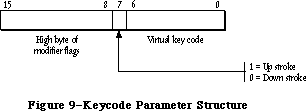 Figure 9–Keycode Parameter Structure
The state parameter is a value maintained by the Toolbox. Your application should save it between calls to KeyTrans. If your application changes transData to point to a different 'KCHR' resource, it should reset the state value to 0.
KeyTrans returns a 32-bit value with the structure shown in Figure 10. In this structure, ASCII 1 is the ASCII value of the first character generated by the key code parameter; reserved1 is an extension for future “16-bit ASCII” coding. ASCII 2 and reserved2 have the same meanings for a possible second character generated by key code—for example, if key code designates an alphabetic character with a separate accent character.
Figure 9–Keycode Parameter Structure
The state parameter is a value maintained by the Toolbox. Your application should save it between calls to KeyTrans. If your application changes transData to point to a different 'KCHR' resource, it should reset the state value to 0.
KeyTrans returns a 32-bit value with the structure shown in Figure 10. In this structure, ASCII 1 is the ASCII value of the first character generated by the key code parameter; reserved1 is an extension for future “16-bit ASCII” coding. ASCII 2 and reserved2 have the same meanings for a possible second character generated by key code—for example, if key code designates an alphabetic character with a separate accent character.
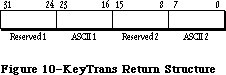 Figure 10–KeyTrans Return Structure
Assembly-language note: The macro you invoke to call KeyTrans from assembly
language is named _KeyTrans. Its parameters are
passed on the stack.
_______________________________________________________________________________
»Miscellaneous Routines
FUNCTION TickCount : LONGINT;
TickCount returns the current number of ticks (sixtieths of a second) since the system last started up.
Warning: Don’t rely on the tick count being exact; it will usually be
accurate to within one tick, but may be off by more than that. The
tick count is incremented during the vertical retrace interrupt,
but it’s possible for this interrupt to be disabled. Furthermore,
don’t rely on the tick count being incremented to a certain value,
such as testing whether it has become equal to its old value plus 1;
check instead for “greater than or equal to” (since an interrupt
task may keep control for more than one tick).
Assembly-language note: The value returned by this function is also contained
in the global variable Ticks.
FUNCTION GetDblTime : LONGINT; [Not in ROM]
GetDblTime returns the suggested maximum difference (in ticks) that should exist between the times of a mouse-up event and a mouse-down event for those two mouse clicks to be considered a double-click. The user can adjust this value by means of the Control Panel desk accessory.
Assembly-language note: This value is available to assembly-language
programmers in the global variable DoubleTime.
FUNCTION GetCaretTime : LONGINT; [Not in ROM]
GetCaretTime returns the time (in ticks) between blinks of the “caret” (usually a vertical bar) marking the insertion point in editable text. If you aren’t using TextEdit, you’ll need to cause the caret to blink yourself; on every pass through your program’s main event loop, you should check this value against the elapsed time since the last blink of the caret. The user can adjust this value by means of the Control Panel desk accessory.
Assembly-language note: This value is available to assembly-language
programmers in the global variable CaretTime.
_______________________________________________________________________________
»THE JOURNALING MECHANISM
_______________________________________________________________________________
So far, this chapter has described the Event Manager as responding to events generated by users—keypresses, mouse clicks, disk insertions, and so on. By using the Event Manager’s journaling mechanism, though, you can “decouple” the Event Manager from the user and feed it events from some other source. Such a source might be a file into which have been recorded all the events that occurred during some portion of a user’s session with the Macintosh. This section briefly describes the journaling mechanism and some examples of its use, and then gives the technical information you’ll need if you want to use this mechanism yourself.
Note: The journaling mechanism can be accessed only through assembly
language; Pascal programmers may want to skip this discussion.
In the usual sense, “journaling” means the recording of a sequence of user-generated events into a file; specifically, this file is a recording of all calls to the Event Manager routines GetNextEvent, EventAvail, GetMouse, Button, GetKeys, and TickCount. When a journal is being recorded, every call to any of these routines is sent to a journaling device driver, which records the call
(and the results of the call) in a file. When the journal is played back, these recorded Event Manager calls are taken from the journal file and sent directly to the Event Manager. The result is that the recorded sequence of user-generated events is reproduced when the journal is played back. The Macintosh Guided Tour is an example of such a journal.
Using the journaling mechanism need not involve a file. Before Macintosh was introduced, Macintosh Software Engineering created a special desk accessory of its own for testing Macintosh software. This desk accessory, which was based on the journaling mechanism, didn’t use a file—it generated events randomly, putting Macintosh “through its paces” for long periods of time without requiring a user’s attention.
So, the Event Manager’s journaling mechanism has a much broader utility than a mechanism simply for “journaling” as it’s normally defined. With the journaling mechanism, you can decouple the Event Manager from the user and feed it events from a journaling device driver of your own design. Figure 11 illustrates what happens when the journaling mechanism is off, in recording mode, and in playback mode.
Figure 10–KeyTrans Return Structure
Assembly-language note: The macro you invoke to call KeyTrans from assembly
language is named _KeyTrans. Its parameters are
passed on the stack.
_______________________________________________________________________________
»Miscellaneous Routines
FUNCTION TickCount : LONGINT;
TickCount returns the current number of ticks (sixtieths of a second) since the system last started up.
Warning: Don’t rely on the tick count being exact; it will usually be
accurate to within one tick, but may be off by more than that. The
tick count is incremented during the vertical retrace interrupt,
but it’s possible for this interrupt to be disabled. Furthermore,
don’t rely on the tick count being incremented to a certain value,
such as testing whether it has become equal to its old value plus 1;
check instead for “greater than or equal to” (since an interrupt
task may keep control for more than one tick).
Assembly-language note: The value returned by this function is also contained
in the global variable Ticks.
FUNCTION GetDblTime : LONGINT; [Not in ROM]
GetDblTime returns the suggested maximum difference (in ticks) that should exist between the times of a mouse-up event and a mouse-down event for those two mouse clicks to be considered a double-click. The user can adjust this value by means of the Control Panel desk accessory.
Assembly-language note: This value is available to assembly-language
programmers in the global variable DoubleTime.
FUNCTION GetCaretTime : LONGINT; [Not in ROM]
GetCaretTime returns the time (in ticks) between blinks of the “caret” (usually a vertical bar) marking the insertion point in editable text. If you aren’t using TextEdit, you’ll need to cause the caret to blink yourself; on every pass through your program’s main event loop, you should check this value against the elapsed time since the last blink of the caret. The user can adjust this value by means of the Control Panel desk accessory.
Assembly-language note: This value is available to assembly-language
programmers in the global variable CaretTime.
_______________________________________________________________________________
»THE JOURNALING MECHANISM
_______________________________________________________________________________
So far, this chapter has described the Event Manager as responding to events generated by users—keypresses, mouse clicks, disk insertions, and so on. By using the Event Manager’s journaling mechanism, though, you can “decouple” the Event Manager from the user and feed it events from some other source. Such a source might be a file into which have been recorded all the events that occurred during some portion of a user’s session with the Macintosh. This section briefly describes the journaling mechanism and some examples of its use, and then gives the technical information you’ll need if you want to use this mechanism yourself.
Note: The journaling mechanism can be accessed only through assembly
language; Pascal programmers may want to skip this discussion.
In the usual sense, “journaling” means the recording of a sequence of user-generated events into a file; specifically, this file is a recording of all calls to the Event Manager routines GetNextEvent, EventAvail, GetMouse, Button, GetKeys, and TickCount. When a journal is being recorded, every call to any of these routines is sent to a journaling device driver, which records the call
(and the results of the call) in a file. When the journal is played back, these recorded Event Manager calls are taken from the journal file and sent directly to the Event Manager. The result is that the recorded sequence of user-generated events is reproduced when the journal is played back. The Macintosh Guided Tour is an example of such a journal.
Using the journaling mechanism need not involve a file. Before Macintosh was introduced, Macintosh Software Engineering created a special desk accessory of its own for testing Macintosh software. This desk accessory, which was based on the journaling mechanism, didn’t use a file—it generated events randomly, putting Macintosh “through its paces” for long periods of time without requiring a user’s attention.
So, the Event Manager’s journaling mechanism has a much broader utility than a mechanism simply for “journaling” as it’s normally defined. With the journaling mechanism, you can decouple the Event Manager from the user and feed it events from a journaling device driver of your own design. Figure 11 illustrates what happens when the journaling mechanism is off, in recording mode, and in playback mode.
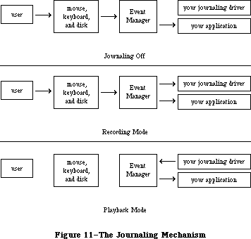 Figure 11–The Journaling Mechanism
_______________________________________________________________________________
»Writing Your Own Journaling Device Driver
If you want to implement journaling in a new way, you’ll need to write your own journaling device driver. Details about how to do this are given below; however, you must already have read about writing your own device driver in the Device Manager chapter. Furthermore, if you want to implement your journaling device driver as a desk accessory, you’ll have to be familiar with details given in the Desk Manager chapter.
Whenever a call is made to any of the Event Manager routines GetNextEvent, EventAvail, GetMouse, Button, GetKeys, and TickCount, the information returned by the routine is passed to the journaling device driver by means of a Control call. The routine makes the Control call to the journaling device driver with the reference number stored in the global variable JournalRef; the journaling device driver should put its reference number in this variable when it’s opened.
You control whether the journaling mechanism is playing or recording by setting the global variable JournalFlag to a negative or positive value. Before the Event Manager routine makes the Control call, it copies one of the following global constants into the csCode parameter of the Control call, depending on the value of JournalFlag:
JournalFlag Value of csCode Meaning
Negative jPlayCtl .EQU 16 Journal in playback mode
Positive jRecordCtl .EQU 17 Journal in recording mode
If you set the value of JournalFlag to 0, the Control call won’t be made at all.
Before the Event Manager routine makes the Control call, it copies into csParam a pointer to the actual data being polled by the routine (for example, a pointer to a keyMap for GetKeys, or a pointer to an event record for GetNextEvent). It also copies, into csParam+4, a journal code designating which routine is making the call:
Control call csParam contains Journal code
made during: pointer to: at csParam+4:
TickCount Long word jcTickCount .EQU 0
GetMouse Point jcGetMouse .EQU 1
Button Boolean jcButton .EQU 2
GetKeys KeyMap jcGetKeys .EQU 3
GetNextEvent Event record jcEvent .EQU 4
EventAvail Event record jcEvent .EQU 4
_______________________________________________________________________________
»SUMMARY OF THE TOOLBOX EVENT MANAGER
_______________________________________________________________________________
Constants
CONST
{ Event codes }
nullEvent = 0; {null}
mouseDown = 1; {mouse-down}
mouseUp = 2; {mouse-up}
keyDown = 3; {key-down}
keyUp = 4; {key-up}
autoKey = 5; {auto-key}
updateEvt = 6; {update}
diskEvt = 7; {disk-inserted}
activateEvt = 8; {activate}
networkEvt = 10; {network}
driverEvt = 11; {device driver}
app1Evt = 12; {application-defined}
app2Evt = 13; {application-defined}
app3Evt = 14; {application-defined}
app4Evt = 15; {application-defined}
{ Masks for keyboard event message }
charCodeMask = $000000FF; {character code}
keyCodeMask = $0000FF00; {key code}
{ Masks for forming event mask }
mDownMask = 2; {mouse-down}
mUpMask = 4; {mouse-up}
keyDownMask = 8; {key-down}
keyUpMask = 16; {key-up}
autoKeyMask = 32; {auto-key}
updateMask = 64; {update}
diskMask = 128; {disk-inserted}
activMask = 256; {activate}
networkMask = 1024; {network}
driverMask = 2048; {device driver}
app1Mask = 4096; {application-defined}
app2Mask = 8192; {application-defined}
app3Mask = 16384; {application-defined}
app4Mask = -32768; {application-defined}
{ Modifier flags in event record }
activeFlag = 1; {set if window being activated}
btnState = 128; {set if mouse button up}
cmdKey = 256; {set if Command key down}
shiftKey = 512; {set if Shift key down}
alphaLock = 1024; {set if Caps Lock key down}
optionKey = 2048; {set if Option key down}
ControlKey = 4096; {set if Control key down}
_______________________________________________________________________________
Data Types
TYPE
EventRecord = RECORD
what: INTEGER; {event code}
message: LONGINT; {event message}
when: LONGINT; {ticks since startup}
where: Point; {mouse location}
modifiers: INTEGER {modifier flags}
END;
KeyMap = PACKED ARRAY[0..127] OF BOOLEAN;
_______________________________________________________________________________
Routines
Accessing Events
FUNCTION GetNextEvent (eventMask: INTEGER;
VAR theEvent: EventRecord) : BOOLEAN;
FUNCTION EventAvail (eventMask: INTEGER;
VAR theEvent: EventRecord) : BOOLEAN;
Reading the Mouse
PROCEDURE GetMouse (VAR mouseLoc: Point);
FUNCTION Button : BOOLEAN;
FUNCTION StillDown : BOOLEAN;
FUNCTION WaitMouseUp : BOOLEAN;
Reading the Keyboard and Keypad
PROCEDURE GetKeys (VAR theKeys: KeyMap);
FUNCTION KeyTrans (transData: Ptr; keycode: Integer;
VAR state: LONGINT) : LONGINT; [256K ROM]
Miscellaneous Routines
FUNCTION TickCount : LONGINT;
FUNCTION GetDblTime : LONGINT; [Not in ROM]
FUNCTION GetCaretTime : LONGINT; [Not in ROM]
_______________________________________________________________________________
Event Message in Event Record
Event type Event message
Keyboard Character code, key code, and ADB address field
Activate, update Pointer to window
Disk-inserted Drive number in low-order word, File Manager
result code in high-order word
Mouse-down, Undefined
mouse-up, null
Network Handle to parameter block
Device driver See chapter describing driver
Application-defined Whatever you wish
_______________________________________________________________________________
Assembly-Language Information
Constants
;Event codes
nullEvt .EQU 0 ;null
mButDwnEvt .EQU 1 ;mouse-down
mButUpEvt .EQU 2 ;mouse-up
keyDwnEvt .EQU 3 ;key-down
keyUpEvt .EQU 4 ;key-up
autoKeyEvt .EQU 5 ;auto-key
updatEvt .EQU 6 ;update
diskInsertEvt .EQU 7 ;disk-inserted
activateEvt .EQU 8 ;activate
networkEvt .EQU 10 ;network
ioDrvrEvt .EQU 11 ;device driver
app1Evt .EQU 12 ;application-defined
app2Evt .EQU 13 ;application-defined
app3Evt .EQU 14 ;application-defined
app4Evt .EQU 15 ;application-defined
; Modifier flags in event record
activeFlag .EQU 0 ;set if window being activated
btnState .EQU 2 ;set if mouse button up
cmdKey .EQU 3 ;set if Command key down
shiftKey .EQU 4 ;set if Shift key down
alphaLock .EQU 5 ;set if Caps Lock key down
optionKey .EQU 6 ;set if Option key down
; Journaling mechanism Control call
jPlayCtl .EQU 16 ;journal in playback mode
jRecordCtl .EQU 17 ;journal in recording mode
jcTickCount .EQU 0 ;journal code for TickCount
jcGetMouse .EQU 1 ;journal code for GetMouse
jcButton .EQU 2 ;journal code for Button
jcGetKeys .EQU 3 ;journal code for GetKeys
jcEvent .EQU 4 ;journal code for GetNextEvent and EventAvail
Event Record Data Structure
evtNum Event code (word)
evtMessage Event message (long)
evtTicks Ticks since startup (long)
evtMouse Mouse location (point; long)
evtMeta State of modifier keys (byte)
evtMBut State of mouse button (byte)
evtBlkSize Size in bytes of event record
Variables
KeyThresh Auto-key threshold (word)
KeyRepThresh Auto-key rate (word)
WindowList 0 if using events but not windows (long)
ScrDmpEnb 0 if GetNextEvent shouldn't process Command-Shift-number
combinations (byte)
Ticks Current number of ticks since system startup (long)
DoubleTime Double-click interval in ticks (long)
CaretTime Caret-blink interval in ticks (long)
JournalRef Reference number of journaling device driver (word)
JournalFlag Journaling mode (word)
Further Reference:
_______________________________________________________________________________
OS Event Manager
Technical Note #3, Command-Shift-Number Keys
Technical Note #5, Using Modeless Dialogs from Desk Accessories
Technical Note #85, GetNextEvent; Blinking Apple Menu
Figure 11–The Journaling Mechanism
_______________________________________________________________________________
»Writing Your Own Journaling Device Driver
If you want to implement journaling in a new way, you’ll need to write your own journaling device driver. Details about how to do this are given below; however, you must already have read about writing your own device driver in the Device Manager chapter. Furthermore, if you want to implement your journaling device driver as a desk accessory, you’ll have to be familiar with details given in the Desk Manager chapter.
Whenever a call is made to any of the Event Manager routines GetNextEvent, EventAvail, GetMouse, Button, GetKeys, and TickCount, the information returned by the routine is passed to the journaling device driver by means of a Control call. The routine makes the Control call to the journaling device driver with the reference number stored in the global variable JournalRef; the journaling device driver should put its reference number in this variable when it’s opened.
You control whether the journaling mechanism is playing or recording by setting the global variable JournalFlag to a negative or positive value. Before the Event Manager routine makes the Control call, it copies one of the following global constants into the csCode parameter of the Control call, depending on the value of JournalFlag:
JournalFlag Value of csCode Meaning
Negative jPlayCtl .EQU 16 Journal in playback mode
Positive jRecordCtl .EQU 17 Journal in recording mode
If you set the value of JournalFlag to 0, the Control call won’t be made at all.
Before the Event Manager routine makes the Control call, it copies into csParam a pointer to the actual data being polled by the routine (for example, a pointer to a keyMap for GetKeys, or a pointer to an event record for GetNextEvent). It also copies, into csParam+4, a journal code designating which routine is making the call:
Control call csParam contains Journal code
made during: pointer to: at csParam+4:
TickCount Long word jcTickCount .EQU 0
GetMouse Point jcGetMouse .EQU 1
Button Boolean jcButton .EQU 2
GetKeys KeyMap jcGetKeys .EQU 3
GetNextEvent Event record jcEvent .EQU 4
EventAvail Event record jcEvent .EQU 4
_______________________________________________________________________________
»SUMMARY OF THE TOOLBOX EVENT MANAGER
_______________________________________________________________________________
Constants
CONST
{ Event codes }
nullEvent = 0; {null}
mouseDown = 1; {mouse-down}
mouseUp = 2; {mouse-up}
keyDown = 3; {key-down}
keyUp = 4; {key-up}
autoKey = 5; {auto-key}
updateEvt = 6; {update}
diskEvt = 7; {disk-inserted}
activateEvt = 8; {activate}
networkEvt = 10; {network}
driverEvt = 11; {device driver}
app1Evt = 12; {application-defined}
app2Evt = 13; {application-defined}
app3Evt = 14; {application-defined}
app4Evt = 15; {application-defined}
{ Masks for keyboard event message }
charCodeMask = $000000FF; {character code}
keyCodeMask = $0000FF00; {key code}
{ Masks for forming event mask }
mDownMask = 2; {mouse-down}
mUpMask = 4; {mouse-up}
keyDownMask = 8; {key-down}
keyUpMask = 16; {key-up}
autoKeyMask = 32; {auto-key}
updateMask = 64; {update}
diskMask = 128; {disk-inserted}
activMask = 256; {activate}
networkMask = 1024; {network}
driverMask = 2048; {device driver}
app1Mask = 4096; {application-defined}
app2Mask = 8192; {application-defined}
app3Mask = 16384; {application-defined}
app4Mask = -32768; {application-defined}
{ Modifier flags in event record }
activeFlag = 1; {set if window being activated}
btnState = 128; {set if mouse button up}
cmdKey = 256; {set if Command key down}
shiftKey = 512; {set if Shift key down}
alphaLock = 1024; {set if Caps Lock key down}
optionKey = 2048; {set if Option key down}
ControlKey = 4096; {set if Control key down}
_______________________________________________________________________________
Data Types
TYPE
EventRecord = RECORD
what: INTEGER; {event code}
message: LONGINT; {event message}
when: LONGINT; {ticks since startup}
where: Point; {mouse location}
modifiers: INTEGER {modifier flags}
END;
KeyMap = PACKED ARRAY[0..127] OF BOOLEAN;
_______________________________________________________________________________
Routines
Accessing Events
FUNCTION GetNextEvent (eventMask: INTEGER;
VAR theEvent: EventRecord) : BOOLEAN;
FUNCTION EventAvail (eventMask: INTEGER;
VAR theEvent: EventRecord) : BOOLEAN;
Reading the Mouse
PROCEDURE GetMouse (VAR mouseLoc: Point);
FUNCTION Button : BOOLEAN;
FUNCTION StillDown : BOOLEAN;
FUNCTION WaitMouseUp : BOOLEAN;
Reading the Keyboard and Keypad
PROCEDURE GetKeys (VAR theKeys: KeyMap);
FUNCTION KeyTrans (transData: Ptr; keycode: Integer;
VAR state: LONGINT) : LONGINT; [256K ROM]
Miscellaneous Routines
FUNCTION TickCount : LONGINT;
FUNCTION GetDblTime : LONGINT; [Not in ROM]
FUNCTION GetCaretTime : LONGINT; [Not in ROM]
_______________________________________________________________________________
Event Message in Event Record
Event type Event message
Keyboard Character code, key code, and ADB address field
Activate, update Pointer to window
Disk-inserted Drive number in low-order word, File Manager
result code in high-order word
Mouse-down, Undefined
mouse-up, null
Network Handle to parameter block
Device driver See chapter describing driver
Application-defined Whatever you wish
_______________________________________________________________________________
Assembly-Language Information
Constants
;Event codes
nullEvt .EQU 0 ;null
mButDwnEvt .EQU 1 ;mouse-down
mButUpEvt .EQU 2 ;mouse-up
keyDwnEvt .EQU 3 ;key-down
keyUpEvt .EQU 4 ;key-up
autoKeyEvt .EQU 5 ;auto-key
updatEvt .EQU 6 ;update
diskInsertEvt .EQU 7 ;disk-inserted
activateEvt .EQU 8 ;activate
networkEvt .EQU 10 ;network
ioDrvrEvt .EQU 11 ;device driver
app1Evt .EQU 12 ;application-defined
app2Evt .EQU 13 ;application-defined
app3Evt .EQU 14 ;application-defined
app4Evt .EQU 15 ;application-defined
; Modifier flags in event record
activeFlag .EQU 0 ;set if window being activated
btnState .EQU 2 ;set if mouse button up
cmdKey .EQU 3 ;set if Command key down
shiftKey .EQU 4 ;set if Shift key down
alphaLock .EQU 5 ;set if Caps Lock key down
optionKey .EQU 6 ;set if Option key down
; Journaling mechanism Control call
jPlayCtl .EQU 16 ;journal in playback mode
jRecordCtl .EQU 17 ;journal in recording mode
jcTickCount .EQU 0 ;journal code for TickCount
jcGetMouse .EQU 1 ;journal code for GetMouse
jcButton .EQU 2 ;journal code for Button
jcGetKeys .EQU 3 ;journal code for GetKeys
jcEvent .EQU 4 ;journal code for GetNextEvent and EventAvail
Event Record Data Structure
evtNum Event code (word)
evtMessage Event message (long)
evtTicks Ticks since startup (long)
evtMouse Mouse location (point; long)
evtMeta State of modifier keys (byte)
evtMBut State of mouse button (byte)
evtBlkSize Size in bytes of event record
Variables
KeyThresh Auto-key threshold (word)
KeyRepThresh Auto-key rate (word)
WindowList 0 if using events but not windows (long)
ScrDmpEnb 0 if GetNextEvent shouldn't process Command-Shift-number
combinations (byte)
Ticks Current number of ticks since system startup (long)
DoubleTime Double-click interval in ticks (long)
CaretTime Caret-blink interval in ticks (long)
JournalRef Reference number of journaling device driver (word)
JournalFlag Journaling mode (word)
Further Reference:
_______________________________________________________________________________
OS Event Manager
Technical Note #3, Command-Shift-Number Keys
Technical Note #5, Using Modeless Dialogs from Desk Accessories
Technical Note #85, GetNextEvent; Blinking Apple Menu
The Vertical Retrace Manager
_______________________________________________________________________________
THE VERTICAL RETRACE MANAGER
_______________________________________________________________________________
About This Chapter
About the Vertical Retrace Manager
Using the Vertical Retrace Manager
Vertical Retrace Manager Routines
Summary of the Vertical Retrace Manager
_______________________________________________________________________________
»ABOUT THIS CHAPTER
_______________________________________________________________________________
This chapter describes the Vertical Retrace Manager, the part of the Operating System that schedules and performs recurrent tasks during vertical retrace interrupts. It describes how your application can install and remove its own recurrent tasks.
You should already be familiar with:
• events, as discussed in the Toolbox Event Manager chapter
• interrupts, as described in the Device Manager chapter
_______________________________________________________________________________
»ABOUT THE VERTICAL RETRACE MANAGER
_______________________________________________________________________________
The Macintosh video circuitry generates a vertical retrace interrupt, also known as the vertical blanking (or VBL) interrupt, 60 times a second while the beam of the display tube returns from the bottom of the screen to the top to display the next frame. This interrupt is used as a convenient time for performing the following sequence of recurrent system tasks:
1. Increment the number of ticks since system startup (every interrupt).
You can get this number by calling the Toolbox Event Manager function
TickCount.
2. Check whether the stack has expanded into the heap; if so, it calls
the System Error Handler (every interrupt).
3. Handle cursor movement (every interrupt).
4. Post a mouse event if the state of the mouse button changed from its
previous state and then remained unchanged for four interrupts (every
other interrupt).
5. Reset the keyboard if it’s been reattached after having been detached
(every 32 interrupts).
6. Post a disk-inserted event if the user has inserted a disk or taken
any other action that requires a volume to be mounted (every 30
interrupts).
These tasks must execute at regular intervals based on the “heartbeat” of the Macintosh, and shouldn’t be changed.
Tasks performed during the vertical retrace interrupt are known as VBL tasks. An application can add any number of its own VBL tasks for the Vertical Retrace Manager to execute. VBL tasks can be set to execute at any frequency (up to once per vertical retrace interrupt). For example, an electronic mail application might add a VBL task that checks every tenth of a second (every six interrupts) to see if it has received any messages. These tasks can perform any desired action as long as they don’t make any calls to the Memory Manager, directly or indirectly, and don’t depend on handles to unlocked blocks being valid. They must preserve all registers other than A0-A3 and D0-D3. If they use application globals, they must also ensure that register A5 contains the address of the boundary between the application globals and the application parameters; for details, see SetCurrentA5 and SetA5 in Macintosh Technical Note #208.
X-Ref: Technical Note #208
Warning: When interrupts are disabled (such as during a disk access), or
when VBL tasks take longer than about a sixtieth of a second to
perform, one or more vertical retrace interrupts may be missed,
thereby affecting the performance of certain VBL tasks. For
instance, while a disk is being accessed, the updating of the
cursor movement may be irregular.
Note: To perform periodic actions that do allocate and release memory, you
can use the Desk Manager procedure SystemTask. Or, since the first
thing the Vertical Retrace Manager does during a vertical retrace
interrupt is increment the tick count, you can call TickCount
repeatedly and perform periodic actions whenever a specific number
of ticks have elapsed.
Information describing each VBL task is contained in the vertical retrace queue. The vertical retrace queue is a standard Macintosh Operating System queue, as described in the Operating System Utilities chapter. Each entry in the vertical retrace queue has the following structure:
TYPE VBLTask = RECORD
qLink: QElemPtr; {next queue entry}
qType: INTEGER; {queue type}
vblAddr: ProcPtr; {pointer to task}
vblCount: INTEGER; {task frequency}
vblPhase: INTEGER {task phase}
END;
QLink points to the next entry in the queue, and qType indicates the queue type, which must be ORD(vType).
VBLAddr contains a pointer to the task. VBLCount specifies the number of ticks between successive calls to the task. This value is decremented each sixtieth of a second until it reaches 0, at which point the task is called. The task must then reset vblCount, or its entry will be removed from the queue after it has been executed. VBLPhase contains an integer (smaller than vblCount) used to modify vblCount when the task is first added to the queue. This ensures that two or more tasks added to the queue at the same time with the same vblCount value will be out of phase with each other, and won’t be called during the same interrupt. Unless there are many tasks to be added to the queue at the same time, vblPhase can usually be set to 0.
The Vertical Retrace Manager uses bit 6 of the queue flags field in the queue header to indicate when a task is being executed:
Bit Meaning
6 Set if a task is being executed
Assembly-language note: Assembly-programmers can use the global constant
inVBL to test this bit.
_______________________________________________________________________________
»USING THE VERTICAL RETRACE MANAGER
_______________________________________________________________________________
The Vertical Retrace Manager is automatically initialized each time the system starts up. To add a VBL task to the vertical retrace queue, call VInstall. When your application no longer wants a task to be executed, it can remove the task from the vertical retrace queue by calling VRemove. A VBL task shouldn’t call VRemove to remove its entry from the queue—either the application should call VRemove, or the task should simply not reset the vblCount field of the queue entry.
Assembly-language note: VBL tasks may use registers A0-A3 and D0-D3, and
must save and restore any additional registers
used. They must exit with an RTS instruction.
If you’d like to manipulate the contents of the vertical retrace queue directly, you can get a pointer to the header of the vertical retrace queue by calling GetVBLQHdr.
With the advent of slots, a variety of screens are available, each with potentially different vertical retrace periods. The Vertical Retrace Manager has been extended to provide flexible, slot-specific video-interrupt handling on the Macintosh II. These changes are mostly transparent to existing applications.
Several video cards can be installed on a single system. The user can, at any time, designate a particular slot as the primary video slot for the system. If at system startup, no device is designated, the Start Manager selects one (see the Start Manager chapter for details).
Instead of maintaining a single vertical retrace queue, the Vertical Retrace Manager now maintains a separate queue for each connected video device; associated with each queue is the rate at which the device’s vertical retrace interrupt occurs. When interrupts occur for a particular video slot, the Vertical Retrace Manager executes any tasks in the queue for that slot.
For compatibility with existing software, a special system-generated interrupt handles the execution of tasks previously performed during the vertical retrace interrupt. This special interrupt, generated 60.15 times a second (identical to the retrace rate on the Macintosh Plus), mimics the vertical retrace interrupt and ensures that application tasks installed with the VInstall function, as well as periodic system tasks such as updating the tick count and checking whether the stack has expanded into the heap, are performed as usual.
You can still use the VInstall function as a way of performing recurrent tasks based on ticks. Be aware, however, that these tasks will no longer be tied to the actual retrace rate of the video screen.
To install a task whose execution is tied to the vertical retrace period of a particular video device, call SlotVInstall using the VBLTask queue element; as before qType must be ORD(vType). The Vertical Retrace Manager interprets the vblCount field in terms of the rate that the specified slot generates vertical retrace interrupts. On the current Macintosh II monitors, for instance, the interrupt occurs every 1/67th of a second; specifying a vblCount of 10 means that the task will be executed every 10/67ths of a second. The value of vblCount is decremented every 1/67th of a second until it reaches 0, at which point the task is called. To remove a slot-specific task, call SlotVRemove.
The AttachVBL function is used primarily by the Start Manager and Control Panel for designating the primary video device; only applications that shift between multiple video cards will need to call this routine.
Slot interrupt handlers for video cards need to call the DoVBLTask function; this causes the Vertical Retrace Manager to execute any tasks in the queue for that slot.
_______________________________________________________________________________
»VERTICAL RETRACE MANAGER ROUTINES
_______________________________________________________________________________
FUNCTION VInstall (vblTaskPtr: QElemPtr) : OSErr;
Trap macro _VInstall
On entry A0: vblTaskPtr (pointer)
On exit D0: result code (word)
VInstall adds the VBL task specified by vblTaskPtr to the vertical retrace queue. Your application must fill in all fields of the task except qLink. VInstall returns one of the result codes listed below.
Result codes noErr No error
vTypErr QType field isn’t ORD(vType)
FUNCTION SlotVInstall (vblTaskPtr: QElemPtr; theSlot:INTEGER) : OSErr;
Trap macro _SlotVInstall
On entry A0: vblTaskPtr (pointer)
D0: theSlot (word)
On exit D0: result code (word)
SlotVInstall is identical in function to the VInstall function except that it installs the task in the queue for the device specified by theSlot.
Result codes noErr No error
vTypErr Invalid queue element
slotNumErr Invalid slot number
FUNCTION VRemove (vblTaskPtr: QElemPtr) : OSErr;
Trap macro _VRemove
On entry A0: vblTaskPtr (pointer)
On exit D0: result code (word)
VRemove removes the VBL task specified by vblTaskPtr from the vertical retrace queue. It returns one of the result codes listed below.
Result codes noErr No error
vTypErr QType field isn’t ORD(vType)
qErr Task entry isn’t in the queue
FUNCTION SlotVRemove (vblTaskPtr: QElemPtr; theSlot: INTEGER) : OSErr;
Trap macro _SlotVRemove
On entry A0: vblTaskPtr (pointer)
D0: theSlot (word)
On exit D0: result code (word)
SlotVRemove is identical in function to the VRemove function except that it removes the task from the queue for the slot specified by theSlot.
Result codes noErr No error
vTypErr Invalid queue element
slotNumErr Invalid slot number
FUNCTION GetVBLQHdr : QHdrPtr; [Not in ROM]
GetVBLQHdr returns a pointer to the header of the vertical retrace queue.
Assembly-language note: The global variable VBLQueue contains the header
of the vertical retrace queue.
FUNCTION AttachVBL (theSlot: INTEGER) : OSErr;
Trap macro _AttachVBL
On entry D0: theSlot (word)
On exit D0: result code (word)
AttachVBL makes theSlot the primary video slot, allowing correct cursor updating.
Result codes noErr No error
slotNumErr Invalid slot number
FUNCTION DoVBLTask (theSlot: INTEGER) : OSErr;
Trap macro _DoVBLTask
On entry D0: theSlot (word)
On exit D0: result code (word)
Note: To reduce overhead at interrupt time, instead of executing the
_DoVBLTask trap you can load the jump vector jDoVBLTask into an
address register and execute a JSR instruction using that register.
DoVBLTask causes any VBL tasks in the queue for the specified slot to be executed. If the specified slot is the primary video slot, the position of the cursor will also be updated.
Result codes noErr No error
slotNumErr Invalid slot number
_______________________________________________________________________________
»SUMMARY OF THE VERTICAL RETRACE MANAGER
_______________________________________________________________________________
Constants
CONST
{ Result codes }
noErr = 0; {no error}
qErr = -1; {task entry isn't in the queue}
vTypErr = -2; {qType field isn't ORD(vType)}
_______________________________________________________________________________
Data Types
TYPE
VBLTask = RECORD
qLink: QElemPtr; {next queue entry}
qType: INTEGER; {queue type}
vblAddr: ProcPtr; {pointer to task}
vblCount: INTEGER; {task frequency}
vblPhase: INTEGER {task phase}
END;
_______________________________________________________________________________
Routines
FUNCTION VInstall (vblTaskPtr: QElemPtr) : OSErr;
FUNCTION SlotVInstall (vblTaskPtr: QElemPtr; theSlot:INTEGER) : OSErr;
FUNCTION VRemove (vblTaskPtr: QElemPtr) : OSErr;
FUNCTION SlotVRemove (vblTaskPtr: QElemPtr; theSlot: INTEGER) : OSErr;
FUNCTION GetVBLQHdr : QHdrPtr; [Not in ROM]
FUNCTION AttachVBL (theSlot: INTEGER) : OSErr;
FUNCTION DoVBLTask (theSlot: INTEGER) : OSErr;
_______________________________________________________________________________
Assembly-Language Information
Constants
inVBL .EQU 6 ;set if Vertical Retrace Manager is executing a task
; Result codes
noErr .EQU 0 ;no error
qErr .EQU -1 ;task entry isn't in the queue
vTypErr .EQU -2 ;qType field isn't vType
Structure of Vertical Retrace Queue Entry
qLink Pointer to next queue entry
qType Queue type (word)
vblAddr Address of task
vblCount Task frequency (word)
vblPhase Task phase (word)
Routines
Trap macro On entry On exit
_VInstall A0: vblTaskPtr (ptr) D0: result code (word)
_SlotVInstall A0: vblTaskPtr (pointer) D0: result code (word)
D0: theSlot (word)
_VRemove A0: vblTaskPtr (ptr) D0: result code (word)
_SlotVRemove A0: vblTaskPtr (pointer) D0: result code (word)
D0: theSlot (word)
_AttachVBL D0: theSlot (word) D0: result code (word)
_DoVBLTask D0: theSlot (word) D0: result code (word)
Variables
VBLQueue Vertical retrace queue header (10 bytes)
jDoVBLTask Jump vector for DoVBLTask routine
Further Reference:
_______________________________________________________________________________
Toolbox Event Manager
Device Manager
Start Manager
Technical Note #180, MultiFinder Miscellanea
Technical Note #208, Setting and Restoring A5
Technical Note #221, NuBus Interrupt Latency
“Macintosh Family Hardware Reference”
The Window Manager
_______________________________________________________________________________
THE WINDOW MANAGER
_______________________________________________________________________________
About This Chapter
About the Window Manager
Windows and GrafPorts
Window Regions
Windows and Resources
Window Records
Window Pointers
The WindowRecord Data Type
Color Window Records
Auxiliary Window Records
Window Color Tables
How a Window is Drawn
Making a Window Active: Activate Events
Using the Window Manager
Using Color Windows
Window Manager Routines
Initialization and Allocation
Window Display
Mouse Location
Window Movement and Sizing
Update Region Maintenance
Color Window Routines
Miscellaneous Routines
Advanced Routines
Low-Level Routines
Defining Your Own Windows
The Window Definition Function
The Draw Window Frame Routine
The Hit Routine
The Routine to Calculate Regions
The Initialize Routine
The Dispose Routine
The Grow Routine
The Draw Size Box Routine
The Color Definition Procedure
Formats of Resources for Windows
Summary of the Window Manager
_______________________________________________________________________________
»ABOUT THIS CHAPTER
_______________________________________________________________________________
The Window Manager is the part of the Toolbox that allows you to create, manipulate, and dispose of windows. This chapter describes the Window Manager in detail, including the enhancements to the Window Manager provided for the Macintosh Plus, the Macintosh SE, and the Macintosh II. A new set of Window Manager routines for the Macintosh II supports the use of multiple screen desktops and color windows. New data structures and a new resource type, 'wctb', have been introduced to store color window information. All handling of color windows and multiple screens is transparent to applications that aren’t using the new features.
To make use of the information in this chapter, you should be familiar with
• the drawing environment described in the Color QuickDraw chapter
• the use of resources in an application program, described in the
Resource Manager chapter
You should already be familiar with:
• The basic concepts and structures behind QuickDraw, particularly
points, rectangles, regions, grafPorts, and pictures. You don’t
have to know the QuickDraw routines in order to use the Window
Manager, though you’ll be using QuickDraw to draw inside a window.
• The Toolbox Event Manager.
_______________________________________________________________________________
»ABOUT THE WINDOW MANAGER
_______________________________________________________________________________
The Window Manager is a tool for dealing with windows on the Macintosh screen. The screen represents a working surface or desktop; graphic objects appear on the desktop and can be manipulated with the mouse. A window is an object on the desktop that presents information, such as a document or a message. Windows can be any size or shape, and there can be one or many of them, depending on the application.
Some standard types of windows are predefined. One of these is the document window, as illustrated in Figure 1. Every document window has a 20-pixel-high title bar containing a title that’s centered and in the system font and system font size. In addition, a particular document window may or may not have a close box or a size box; you’ll learn in this chapter how to implement them. There may also be scroll bars along the bottom and/or right edge of a document window. Scroll bars are controls, and are supported by the Control Manager.
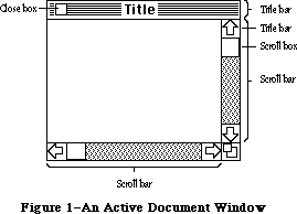 Figure 1–An Active Document Window
Your application can easily create standard types of windows such as document windows, and can also define its own types of windows. Some windows may be created indirectly for you when you use other parts of the Toolbox; an example is the window the Dialog Manager creates to display an alert box. Windows created either directly or indirectly by an application are collectively called application windows. There’s also a class of windows called system windows; these are the windows in which desk accessories are displayed.
The document window shown in Figure 1 is the active (frontmost) window, the one that will be acted on when the user types, gives commands, or whatever is appropriate to the application being used. Its title bar is highlighted—displayed in a distinctive visual way—so that the window will stand out from other, inactive windows that may be on the screen. Since a close box, size box, and scroll bars will have an effect only in an active window, none of them appear in an inactive window (see Figure 2).
Figure 1–An Active Document Window
Your application can easily create standard types of windows such as document windows, and can also define its own types of windows. Some windows may be created indirectly for you when you use other parts of the Toolbox; an example is the window the Dialog Manager creates to display an alert box. Windows created either directly or indirectly by an application are collectively called application windows. There’s also a class of windows called system windows; these are the windows in which desk accessories are displayed.
The document window shown in Figure 1 is the active (frontmost) window, the one that will be acted on when the user types, gives commands, or whatever is appropriate to the application being used. Its title bar is highlighted—displayed in a distinctive visual way—so that the window will stand out from other, inactive windows that may be on the screen. Since a close box, size box, and scroll bars will have an effect only in an active window, none of them appear in an inactive window (see Figure 2).
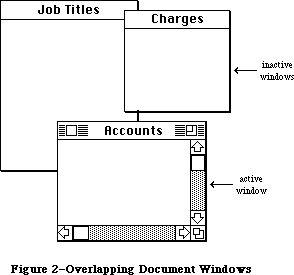 Figure 2–Overlapping Document Windows
Note: If a document window has neither a size box nor scroll bars,
the lines delimiting those areas aren’t drawn, as in the Memo
window in Figure 2.
An important function of the Window Manager is to keep track of overlapping windows. You can draw in any window without running over onto windows in front of it. You can move windows to different places on the screen, change their plane (their front-to-back ordering), or change their size, all without concern for how the various windows overlap. The Window Manager keeps track of any newly exposed areas and provides a convenient mechanism for you to ensure that they’re properly redrawn.
Finally, you can easily set up your application so that mouse actions cause these standard responses inside a document window, or similar responses inside other windows:
• Clicking anywhere in an inactive window makes it the active window
by bringing it to the front and highlighting its title bar.
• Clicking inside the close box of the active window closes the window.
Depending on the application, this may mean that the window disappears
altogether, or a representation of the window (such as an icon) may be
left on the desktop.
• Dragging anywhere inside the title bar of a window (except in the
close box, if any) pulls an outline of the window across the screen,
and releasing the mouse button moves the window to the new location.
If the window isn’t the active window, it becomes the active window
unless the Command key was also held down. A window can never be
moved completely off the screen; by convention, it can’t be moved such
that the visible area of the title bar is less than four pixels square.
• Dragging inside the size box of the active window changes the size of
the window.
For the Macintosh Plus, the Macintosh SE, and the Macintosh II, the following Window Manager routines were changed to support hierarchical menus:
• The InitWindow routine now calls the Menu Manager to calculate menu
bar height, and to draw the empty menu bar. The FindWindow routine
also makes a call to the Menu Manager when testing to see if a point
on the screen has been selected.
For the Macintosh II, the Window Manager has been enhanced to support multiple screen desktops and color windows:
• Color windows can now be created within an application program.
• Because window content regions may be colored on the Macintosh II,
each window’s area is now erased separately. Formerly, the Window
Manager collected the update region of multiple windows into a single
region, then erased this single region to white.
• The standard desktop pattern may be a binary deskPattern or a color
deskCPattern. If the color desktop pattern is enabled, InitWindows
loads the default desktop pixel pattern as well as the standard binary
pattern.
• Windows may be dragged from one screen to another on a system
configured with multiple screens. Changes to the DragGrayRgn routine
allow the object being dragged to be positioned anywhere on the
multiscreen desktop. The GetGrayRgn routine provides a handle to the
global variable GrayRgn, which contains information about the current
desktop.
• The MoveWindow, GrowWindow, and ZoomWindow routines have been modified
to ensure that windows will perform properly in a multiscreen environment.
_______________________________________________________________________________
»WINDOWS AND GRAFPORTS
_______________________________________________________________________________
It’s easy for applications to use windows: To the application, a window is a grafPort that it can draw into like any other with QuickDraw routines. When you create a window, you specify a rectangle that becomes the portRect of the grafPort in which the window contents will be drawn. The bit map for this grafPort, its pen pattern, and other characteristics are the same as the default values set by QuickDraw, except for the character font, which is set to the application font. These characteristics will apply whenever the application draws in the window, and they can easily be changed with QuickDraw routines
(SetPort to make the grafPort the current port, and other routines as appropriate).
There is, however, more to a window than just the grafPort that the application draws in. In a standard document window, for example, the title bar and outline of the window are drawn by the Window Manager, not by the application. The part of a window that the Window Manager draws is called the window frame, since it usually surrounds the rest of the window. For drawing window frames, the Window Manager creates a grafPort that has the entire screen as its portRect; this grafPort is called the Window Manager port.
_______________________________________________________________________________
»WINDOW REGIONS
_______________________________________________________________________________
Every window has the following two regions:
• the content region: the area that your application draws in
• the structure region: the entire window; its complete “structure”
(the content region plus the window frame)
The content region is bounded by the rectangle you specify when you create the window (that is, the portRect of the window’s grafPort); for a document window, it’s the entire portRect. This is where your application presents information and where the size box and scroll bars of a document window are located.
A window may also have any of the regions listed below. Clicking or dragging in one of these regions causes the indicated action.
• A go-away region within the window frame. Clicking in this region of
the active window closes the window.
• A drag region within the window frame. Dragging in this region pulls
an outline of the window across the screen, moves the window to a new
location, and makes it the active window (if it isn’t already) unless
the Command key was held down.
• A grow region, usually within the content region. Dragging in this
region of the active window changes the size of the window. In a
document window, the grow region is in the content region, but in
windows of your own design it may be in either the content region
or the window frame.
Clicking in any region of an inactive window simply makes it the active window.
Note: The results of clicking and dragging that are discussed here don’t
happen automatically; you have to make the right Window Manager
calls to cause them to happen.
Figure 3 illustrates the various regions of a standard document window and its window frame.
Figure 2–Overlapping Document Windows
Note: If a document window has neither a size box nor scroll bars,
the lines delimiting those areas aren’t drawn, as in the Memo
window in Figure 2.
An important function of the Window Manager is to keep track of overlapping windows. You can draw in any window without running over onto windows in front of it. You can move windows to different places on the screen, change their plane (their front-to-back ordering), or change their size, all without concern for how the various windows overlap. The Window Manager keeps track of any newly exposed areas and provides a convenient mechanism for you to ensure that they’re properly redrawn.
Finally, you can easily set up your application so that mouse actions cause these standard responses inside a document window, or similar responses inside other windows:
• Clicking anywhere in an inactive window makes it the active window
by bringing it to the front and highlighting its title bar.
• Clicking inside the close box of the active window closes the window.
Depending on the application, this may mean that the window disappears
altogether, or a representation of the window (such as an icon) may be
left on the desktop.
• Dragging anywhere inside the title bar of a window (except in the
close box, if any) pulls an outline of the window across the screen,
and releasing the mouse button moves the window to the new location.
If the window isn’t the active window, it becomes the active window
unless the Command key was also held down. A window can never be
moved completely off the screen; by convention, it can’t be moved such
that the visible area of the title bar is less than four pixels square.
• Dragging inside the size box of the active window changes the size of
the window.
For the Macintosh Plus, the Macintosh SE, and the Macintosh II, the following Window Manager routines were changed to support hierarchical menus:
• The InitWindow routine now calls the Menu Manager to calculate menu
bar height, and to draw the empty menu bar. The FindWindow routine
also makes a call to the Menu Manager when testing to see if a point
on the screen has been selected.
For the Macintosh II, the Window Manager has been enhanced to support multiple screen desktops and color windows:
• Color windows can now be created within an application program.
• Because window content regions may be colored on the Macintosh II,
each window’s area is now erased separately. Formerly, the Window
Manager collected the update region of multiple windows into a single
region, then erased this single region to white.
• The standard desktop pattern may be a binary deskPattern or a color
deskCPattern. If the color desktop pattern is enabled, InitWindows
loads the default desktop pixel pattern as well as the standard binary
pattern.
• Windows may be dragged from one screen to another on a system
configured with multiple screens. Changes to the DragGrayRgn routine
allow the object being dragged to be positioned anywhere on the
multiscreen desktop. The GetGrayRgn routine provides a handle to the
global variable GrayRgn, which contains information about the current
desktop.
• The MoveWindow, GrowWindow, and ZoomWindow routines have been modified
to ensure that windows will perform properly in a multiscreen environment.
_______________________________________________________________________________
»WINDOWS AND GRAFPORTS
_______________________________________________________________________________
It’s easy for applications to use windows: To the application, a window is a grafPort that it can draw into like any other with QuickDraw routines. When you create a window, you specify a rectangle that becomes the portRect of the grafPort in which the window contents will be drawn. The bit map for this grafPort, its pen pattern, and other characteristics are the same as the default values set by QuickDraw, except for the character font, which is set to the application font. These characteristics will apply whenever the application draws in the window, and they can easily be changed with QuickDraw routines
(SetPort to make the grafPort the current port, and other routines as appropriate).
There is, however, more to a window than just the grafPort that the application draws in. In a standard document window, for example, the title bar and outline of the window are drawn by the Window Manager, not by the application. The part of a window that the Window Manager draws is called the window frame, since it usually surrounds the rest of the window. For drawing window frames, the Window Manager creates a grafPort that has the entire screen as its portRect; this grafPort is called the Window Manager port.
_______________________________________________________________________________
»WINDOW REGIONS
_______________________________________________________________________________
Every window has the following two regions:
• the content region: the area that your application draws in
• the structure region: the entire window; its complete “structure”
(the content region plus the window frame)
The content region is bounded by the rectangle you specify when you create the window (that is, the portRect of the window’s grafPort); for a document window, it’s the entire portRect. This is where your application presents information and where the size box and scroll bars of a document window are located.
A window may also have any of the regions listed below. Clicking or dragging in one of these regions causes the indicated action.
• A go-away region within the window frame. Clicking in this region of
the active window closes the window.
• A drag region within the window frame. Dragging in this region pulls
an outline of the window across the screen, moves the window to a new
location, and makes it the active window (if it isn’t already) unless
the Command key was held down.
• A grow region, usually within the content region. Dragging in this
region of the active window changes the size of the window. In a
document window, the grow region is in the content region, but in
windows of your own design it may be in either the content region
or the window frame.
Clicking in any region of an inactive window simply makes it the active window.
Note: The results of clicking and dragging that are discussed here don’t
happen automatically; you have to make the right Window Manager
calls to cause them to happen.
Figure 3 illustrates the various regions of a standard document window and its window frame.
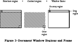 Figure 3–Document Window Regions and Frame
An example of a window that has no drag region is the window that displays an alert box. On the other hand, you could design a window whose drag region is the entire structure region and whose content region is empty; such a window might present a fixed picture rather than information that’s to be manipulated.
Another important window region is the update region. Unlike the regions described above, the update region is dynamic rather than fixed: The Window Manager keeps track of all areas of the content region that have to be redrawn and accumulates them into the update region. For example, if you bring to the front a window that was overlapped by another window, the Window Manager adds the formerly overlapped (now exposed) area of the front window’s content region to its update region. You’ll also accumulate areas into the update region yourself; the Window Manager provides update region maintenance routines for this purpose.
_______________________________________________________________________________
»WINDOWS AND RESOURCES
_______________________________________________________________________________
The general appearance and behavior of a window is determined by a routine called its window definition function, which is stored as a resource in a resource file. The window definition function performs all actions that differ from one window type to another, such as drawing the window frame. The Window Manager calls the window definition function whenever it needs to perform one of these type-dependent actions (passing it a message that tells which action to perform).
The system resource file includes window definition functions for the standard document window and other standard types of windows. If you want to define your own, nonstandard window types, you’ll have to write window definition functions for them, as described later in the section “Defining Your Own Windows”.
When you create a window, you specify its type with a window definition ID, which tells the Window Manager the resource ID of the definition function for that type of window. You can use one of the following constants as a window definition ID to refer to a standard type of window (see Figure 4):
CONST documentProc = 0; {standard document window}
dBoxProc = 1; {alert box or modal dialog box}
plainDBox = 2; {plain box}
altDBoxProc = 3; {plain box with shadow}
noGrowDocProc = 4; {document window without size box}
rDocProc = 16; {rounded-corner window}
Figure 3–Document Window Regions and Frame
An example of a window that has no drag region is the window that displays an alert box. On the other hand, you could design a window whose drag region is the entire structure region and whose content region is empty; such a window might present a fixed picture rather than information that’s to be manipulated.
Another important window region is the update region. Unlike the regions described above, the update region is dynamic rather than fixed: The Window Manager keeps track of all areas of the content region that have to be redrawn and accumulates them into the update region. For example, if you bring to the front a window that was overlapped by another window, the Window Manager adds the formerly overlapped (now exposed) area of the front window’s content region to its update region. You’ll also accumulate areas into the update region yourself; the Window Manager provides update region maintenance routines for this purpose.
_______________________________________________________________________________
»WINDOWS AND RESOURCES
_______________________________________________________________________________
The general appearance and behavior of a window is determined by a routine called its window definition function, which is stored as a resource in a resource file. The window definition function performs all actions that differ from one window type to another, such as drawing the window frame. The Window Manager calls the window definition function whenever it needs to perform one of these type-dependent actions (passing it a message that tells which action to perform).
The system resource file includes window definition functions for the standard document window and other standard types of windows. If you want to define your own, nonstandard window types, you’ll have to write window definition functions for them, as described later in the section “Defining Your Own Windows”.
When you create a window, you specify its type with a window definition ID, which tells the Window Manager the resource ID of the definition function for that type of window. You can use one of the following constants as a window definition ID to refer to a standard type of window (see Figure 4):
CONST documentProc = 0; {standard document window}
dBoxProc = 1; {alert box or modal dialog box}
plainDBox = 2; {plain box}
altDBoxProc = 3; {plain box with shadow}
noGrowDocProc = 4; {document window without size box}
rDocProc = 16; {rounded-corner window}
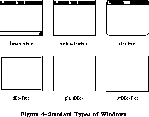 Figure 4–Standard Types of Windows
DocumentProc represents a standard document window that may or may not contain a size box; noGrowDocProc is exactly the same except that the window must not contain a size box. If you’re working with a number of document windows that need to be treated similarly, but some will have size boxes and some won’t, you can use documentProc for all of them. If none of the windows will have size boxes, however, it’s more convenient to use noGrowDocProc.
The dBoxProc type of window resembles an alert box or a “modal” dialog box (the kind that requires the user to respond before doing any other work on the desktop). It’s a rectangular window with no go-away region, drag region, or grow region and with a two-pixel-thick border two pixels in from the edge. It has no special highlighted state because alerts and modal dialogs are always displayed in the frontmost window. PlainDBox and altDBoxProc are variations of dBoxProc: plainDBox is just a plain box with no inner border, and altDBoxProc has a two-pixel-thick shadow instead of a border.
The rDocProc type of window is like a document window with no grow region, with rounded corners, and with a method of highlighting that inverts the entire title bar (that is, changes white to black and vice versa). It’s often used for desk accessories. Rounded-corner windows are drawn by the QuickDraw procedure FrameRoundRect, which requires the diameters of curvature to be passed as parameters. For an rDocProc type of window, the diameters of curvature are both 16. You can add a number from 1 to 7 to rDocProc to get different diameters:
Window definition ID Diameters of curvature
rDocProc 16, 16
rDocProc + 1 4, 4
rDocProc + 2 6, 6
rDocProc + 3 8, 8
rDocProc + 4 10, 10
rDocProc + 5 12, 12
rDocProc + 6 20, 20
rDocProc + 7 24, 24
To create a window, the Window Manager needs to know not only the window definition ID but also other information specific to this window, such as its title (if any), its location, and its plane. You can supply all the needed information in individual parameters to a Window Manager routine or, better yet, you can store it as a single resource in a resource file and just pass the resource ID. This type of resource is called a window template. Using window templates simplifies the process of creating a number of windows of the same type. More important, it allows you to isolate specific window descriptions from your application’s code. Translation of window titles to another language, for example, would require only a change to the resource file.
_______________________________________________________________________________
»WINDOW RECORDS
_______________________________________________________________________________
The Window Manager keeps all the information it requires for its operations on a particular window in a window record. The window record contains the following:
• The grafPort for the window.
• A handle to the window definition function.
• A handle to the window’s title, if any.
• The window class, which tells whether the window is a system window,
a dialog or alert window, or a window created directly by the
application.
• A handle to the window’s control list, which is a list of all the
controls, if any, in the window. The Control Manager maintains this
list.
• A pointer to the next window in the window list, which is a list of
all windows on the desktop ordered according to their front-to-back
positions.
The window record also contains an indication of whether the window is currently visible or invisible. These terms refer only to whether the window is drawn in its plane, not necessarily whether you can see it on the screen. If, for example, it’s completely overlapped by another window, it’s still “visible” even though it can’t be seen in its current location.
The 32-bit reference value field of the window record is reserved for use by your application. You specify an initial reference value when you create a window, and can then read or change the reference value whenever you wish. For example, it might be a handle to data associated with the window, such as a TextEdit edit record.
Finally, a window record may contain a handle to a QuickDraw picture of the window contents. For a window whose contents never change, the application can simply have the Window Manager redraw this picture instead of using the update event mechanism. For more information, see “How a Window is Drawn”.
The data type for a window record is called WindowRecord. A window record is referred to by a pointer, as discussed further under “Window Pointers” below. You can store into and access most of the fields of a window record with Window Manager routines, so normally you don’t have to know the exact field names. Occasionally—particularly if you define your own type of window—you may need to know the exact structure; it’s given below under “The WindowRecord Data Type”.
_______________________________________________________________________________
»Window Pointers
There are two types of pointer through which you can access windows: WindowPtr and WindowPeek. Most programmers will only need to use WindowPtr.
The Window Manager defines the following type of window pointer:
TYPE WindowPtr = GrafPtr;
It can do this because the first field of a window record contains the window’s grafPort. This type of pointer can be used to access fields of the grafPort or can be passed to QuickDraw routines that expect pointers to grafPorts as parameters. The application might call such routines to draw into the window, and the Window Manager itself calls them to perform many of its operations. The Window Manager gets the additional information it needs from the rest of the window record beyond the grafPort.
In some cases, however, a more direct way of accessing the window record may be necessary or desirable. For this reason, the Window Manager also defines the following type of window pointer:
TYPE WindowPeek = ^WindowRecord;
Programmers who want to access WindowRecord fields directly must use this type of pointer (which derives its name from the fact that it lets you “peek” at the additional information about the window). A WindowPeek pointer is also used wherever the Window Manager will not be calling QuickDraw routines and will benefit from a more direct means of getting to the data stored in the window record.
Assembly-language note: From assembly language, of course, there’s no type
checking on pointers, and the two types of pointer
are equal.
_______________________________________________________________________________
»The WindowRecord Data Type
The exact data structure of a window record is as follows:
TYPE WindowRecord = RECORD
port: GrafPort; {window's grafPort}
windowKind: INTEGER; {window class}
visible: BOOLEAN; {TRUE if visible}
hilited: BOOLEAN; {TRUE if highlighted}
goAwayFlag: BOOLEAN; {TRUE if has go-away region}
spareFlag: BOOLEAN; {reserved for future use}
strucRgn: RgnHandle; {structure region}
contRgn: RgnHandle; {content region}
updateRgn: RgnHandle; {update region}
windowDefProc: Handle; {window definition function}
dataHandle: Handle; {data used by windowDefProc}
titleHandle: StringHandle;{window's title}
titleWidth: INTEGER; {width of title in pixels}
controlList: ControlHandle; {window's control list}
nextWindow: WindowPeek; {next window in window list}
windowPic: PicHandle; {picture for drawing window}
refCon: LONGINT {window's reference value}
END;
The port is the window’s grafPort.
WindowKind identifies the window class. If negative, it means the window is a system window (it’s the desk accessory’s reference number, as described in the Desk Manager chapter). It may also be one of the following predefined constants:
CONST dialogKind = 2; {dialog or alert window}
userKind = 8; {window created directly by the application}
DialogKind is the window class for a dialog or alert window, whether created by the system or indirectly (via the Dialog Manger) by your application. UserKind represents a window created directly by application calls to the Window Manager; for such windows the application can in fact set the window class to any value greater than 8 if desired.
Note: WindowKind values 0, 1, and 3 through 7 are reserved for future
use by the system.
When visible is TRUE, the window is currently visible.
Hilited and goAwayFlag are checked by the window definition function when it draws the window frame, to determine whether the window should be highlighted and whether it should have a go-away region. For a document window, this means that if hilited is TRUE, the title bar of the window is highlighted, and if goAwayFlag is also TRUE, a close box appears in the highlighted title bar.
Note: The Window Manager sets the visible and hilited flags to TRUE by
storing 255 in them rather than 1. This may cause problems in Lisa
Pascal; to be safe, you should check for the truth or falsity of
these flags by comparing ORD of the flag to 0. For example, you would
check to see if the flag is TRUE with ORD(myWindow^.visible) <> 0.
StrucRgn, contRgn, and updateRgn are region handles, as defined in QuickDraw, to the structure region, content region, and update region of the window. These regions are all in global coordinates.
WindowDefProc is a handle to the window definition function for this type of window. When you create a window, you identify its type with a window definition ID, which is converted into a handle and stored in the windowDefProc field. Thereafter, the Window Manager uses this handle to access the definition function; you should never need to access this field directly.
Note: The high-order byte of the windowDefProc field contains some
additional information that the Window Manager gets from the
window definition ID; for details, see the section “Defining
Your Own Windows”.
X-Ref: Technical Note #212
DataHandle is reserved for use by the window definition function. If the window is one of your own definition, your window definition function may use this field to store and access any desired information. If no more than four bytes of information are needed, the definition function can store the information directly in the dataHandle field rather than use a handle. For example, the definition function for rounded-corner windows uses this field to store the diameters of curvature.
TitleHandle is a string handle to the window’s title, if any.
TitleWidth is the width, in pixels, of the window’s title in the system font and system font size. This width is determined by the Window Manager and is normally of no concern to the application.
ControlList is a control handle to the window’s control list. The ControlHandle data type is defined in the Control Manager.
NextWindow is a pointer to the next window in the window list, that is, the window behind this window. If this window is the farthest back (with no windows between it and the desktop), nextWindow is NIL.
Assembly-language note: The global variable WindowList contains a pointer
to the first window in the window list. Remember
that any window in the list may be invisible.
WindowPic is a handle to a QuickDraw picture of the window contents, or NIL if the application will draw the window contents in response to an update event, as described below under “How a Window is Drawn”.
RefCon is the window’s reference value field, which the application may store into and access for any purpose.
Note: Notice that the go-away, drag, and grow regions are not included
in the window record. Although these are conceptually regions,
they don’t necessarily have the formal data structure for regions
as defined in QuickDraw. The window definition function determines
where these regions are, and it can do so with great flexibility.
_______________________________________________________________________________
»COLOR WINDOW RECORDS
_______________________________________________________________________________
The Window Manager keeps all the information required for drawing color windows in a color window record. The structure and size of a color window record are the same as a regular window record, except that it’s now optionally based on a cGrafPort instead of an old-style grafPort. This allows the window structure and content to use the color capability of the Macintosh II.
All standard window definition procedures can now draw window structure information into a color window port, called the WMgrCPort. The WMgrCPort is analogous to the WMgrPort. See the section “Defining Your Own Windows” for more information on how to use the WMgrCPort correctly.
The new data type CWindowRecord is identical to the old WindowRecord except that its port field is a cGrafPort instead of a grafPort. Because both types of port are the same size and follow the same rules, the old-style and new-style window records are also the same size and have all their fields at the same locations within the record. You can access most of the fields of a window record with Window Manager routines, so for most applications you won’t need to use the fields listed below.
TYPE
CWindowPtr = CGrafPtr;
CWindowPeek = ^CWindowRecord;
CWindowRecord = RECORD {all fields remain the same as before}
port: CGrafPort; {window's CGrafPort}
windowKind: INTEGER; {window class}
visible: BOOLEAN; {TRUE if visible}
hilited: BOOLEAN; {TRUE if highlighted}
goAwayFlag: BOOLEAN; {TRUE if has go-away region}
spareFlag: BOOLEAN; {reserved for future use}
strucRgn: RgnHandle; {structure region}
contRgn: RgnHandle; {content region}
updateRgn: RgnHandle; {update region}
windowDefProc: Handle; {window definition function}
dataHandle: Handle; {data used by windowDefProc}
titleHandle: StringHandle; {window's title}
titleWidth: INTEGER; {width of title in pixels}
controlList: ControlHandle; {window's control list}
nextWindow: CWindowPeek; {next window in window list}
windowPic: PicHandle; {picture for drawing window}
refCon: LONGINT {window's reference value}
END;
All of the old Window Manager routines now accept a CWindowPtr in place of a WindowPtr. If necessary, high-level languages may use type coercion to convert one data type to another. (Another method that allows the use of both types is to define a duplicate set of interfaces, substituting a CWindowPtr for a WindowPtr for convenience or code efficiency.) The two types of window may even be mixed on the same screen; the Window Manager will examine each window’s port field to see which type it is, and draw it in full RGB colors or the original eight QuickDraw colors.
_______________________________________________________________________________
»Auxiliary Window Records
As described earlier in this chapter, windows consist of two parts: a structure region that includes the frame, titlebar, and other window elements, and a content region enclosed within the frame. Applications draw within the content region, and may draw in color by using the NewCWindow routine. Use of the NewWindow routine limits drawing within the contents region to the eight original QuickDraw colors. On the Macintosh II, the structure region is always drawn in the WMgrCPort and has full color capability, independent of the content region.
A new data structure, the auxiliary window record, stores the color information needed for each color window in an independent list. A number of auxiliary window records may exist as a linked list, beginning in the global variable AuxWindowHead. Each auxiliary window record is a relocatable object residing in the application heap. Figure 5 shows an example of a set of auxiliary window records that could be used for an application using a separate window color table for each of the windows. This data structure is known as the AuxWinList, and is simply a linked list where each additional auxiliary window record points to the one after it.
Figure 4–Standard Types of Windows
DocumentProc represents a standard document window that may or may not contain a size box; noGrowDocProc is exactly the same except that the window must not contain a size box. If you’re working with a number of document windows that need to be treated similarly, but some will have size boxes and some won’t, you can use documentProc for all of them. If none of the windows will have size boxes, however, it’s more convenient to use noGrowDocProc.
The dBoxProc type of window resembles an alert box or a “modal” dialog box (the kind that requires the user to respond before doing any other work on the desktop). It’s a rectangular window with no go-away region, drag region, or grow region and with a two-pixel-thick border two pixels in from the edge. It has no special highlighted state because alerts and modal dialogs are always displayed in the frontmost window. PlainDBox and altDBoxProc are variations of dBoxProc: plainDBox is just a plain box with no inner border, and altDBoxProc has a two-pixel-thick shadow instead of a border.
The rDocProc type of window is like a document window with no grow region, with rounded corners, and with a method of highlighting that inverts the entire title bar (that is, changes white to black and vice versa). It’s often used for desk accessories. Rounded-corner windows are drawn by the QuickDraw procedure FrameRoundRect, which requires the diameters of curvature to be passed as parameters. For an rDocProc type of window, the diameters of curvature are both 16. You can add a number from 1 to 7 to rDocProc to get different diameters:
Window definition ID Diameters of curvature
rDocProc 16, 16
rDocProc + 1 4, 4
rDocProc + 2 6, 6
rDocProc + 3 8, 8
rDocProc + 4 10, 10
rDocProc + 5 12, 12
rDocProc + 6 20, 20
rDocProc + 7 24, 24
To create a window, the Window Manager needs to know not only the window definition ID but also other information specific to this window, such as its title (if any), its location, and its plane. You can supply all the needed information in individual parameters to a Window Manager routine or, better yet, you can store it as a single resource in a resource file and just pass the resource ID. This type of resource is called a window template. Using window templates simplifies the process of creating a number of windows of the same type. More important, it allows you to isolate specific window descriptions from your application’s code. Translation of window titles to another language, for example, would require only a change to the resource file.
_______________________________________________________________________________
»WINDOW RECORDS
_______________________________________________________________________________
The Window Manager keeps all the information it requires for its operations on a particular window in a window record. The window record contains the following:
• The grafPort for the window.
• A handle to the window definition function.
• A handle to the window’s title, if any.
• The window class, which tells whether the window is a system window,
a dialog or alert window, or a window created directly by the
application.
• A handle to the window’s control list, which is a list of all the
controls, if any, in the window. The Control Manager maintains this
list.
• A pointer to the next window in the window list, which is a list of
all windows on the desktop ordered according to their front-to-back
positions.
The window record also contains an indication of whether the window is currently visible or invisible. These terms refer only to whether the window is drawn in its plane, not necessarily whether you can see it on the screen. If, for example, it’s completely overlapped by another window, it’s still “visible” even though it can’t be seen in its current location.
The 32-bit reference value field of the window record is reserved for use by your application. You specify an initial reference value when you create a window, and can then read or change the reference value whenever you wish. For example, it might be a handle to data associated with the window, such as a TextEdit edit record.
Finally, a window record may contain a handle to a QuickDraw picture of the window contents. For a window whose contents never change, the application can simply have the Window Manager redraw this picture instead of using the update event mechanism. For more information, see “How a Window is Drawn”.
The data type for a window record is called WindowRecord. A window record is referred to by a pointer, as discussed further under “Window Pointers” below. You can store into and access most of the fields of a window record with Window Manager routines, so normally you don’t have to know the exact field names. Occasionally—particularly if you define your own type of window—you may need to know the exact structure; it’s given below under “The WindowRecord Data Type”.
_______________________________________________________________________________
»Window Pointers
There are two types of pointer through which you can access windows: WindowPtr and WindowPeek. Most programmers will only need to use WindowPtr.
The Window Manager defines the following type of window pointer:
TYPE WindowPtr = GrafPtr;
It can do this because the first field of a window record contains the window’s grafPort. This type of pointer can be used to access fields of the grafPort or can be passed to QuickDraw routines that expect pointers to grafPorts as parameters. The application might call such routines to draw into the window, and the Window Manager itself calls them to perform many of its operations. The Window Manager gets the additional information it needs from the rest of the window record beyond the grafPort.
In some cases, however, a more direct way of accessing the window record may be necessary or desirable. For this reason, the Window Manager also defines the following type of window pointer:
TYPE WindowPeek = ^WindowRecord;
Programmers who want to access WindowRecord fields directly must use this type of pointer (which derives its name from the fact that it lets you “peek” at the additional information about the window). A WindowPeek pointer is also used wherever the Window Manager will not be calling QuickDraw routines and will benefit from a more direct means of getting to the data stored in the window record.
Assembly-language note: From assembly language, of course, there’s no type
checking on pointers, and the two types of pointer
are equal.
_______________________________________________________________________________
»The WindowRecord Data Type
The exact data structure of a window record is as follows:
TYPE WindowRecord = RECORD
port: GrafPort; {window's grafPort}
windowKind: INTEGER; {window class}
visible: BOOLEAN; {TRUE if visible}
hilited: BOOLEAN; {TRUE if highlighted}
goAwayFlag: BOOLEAN; {TRUE if has go-away region}
spareFlag: BOOLEAN; {reserved for future use}
strucRgn: RgnHandle; {structure region}
contRgn: RgnHandle; {content region}
updateRgn: RgnHandle; {update region}
windowDefProc: Handle; {window definition function}
dataHandle: Handle; {data used by windowDefProc}
titleHandle: StringHandle;{window's title}
titleWidth: INTEGER; {width of title in pixels}
controlList: ControlHandle; {window's control list}
nextWindow: WindowPeek; {next window in window list}
windowPic: PicHandle; {picture for drawing window}
refCon: LONGINT {window's reference value}
END;
The port is the window’s grafPort.
WindowKind identifies the window class. If negative, it means the window is a system window (it’s the desk accessory’s reference number, as described in the Desk Manager chapter). It may also be one of the following predefined constants:
CONST dialogKind = 2; {dialog or alert window}
userKind = 8; {window created directly by the application}
DialogKind is the window class for a dialog or alert window, whether created by the system or indirectly (via the Dialog Manger) by your application. UserKind represents a window created directly by application calls to the Window Manager; for such windows the application can in fact set the window class to any value greater than 8 if desired.
Note: WindowKind values 0, 1, and 3 through 7 are reserved for future
use by the system.
When visible is TRUE, the window is currently visible.
Hilited and goAwayFlag are checked by the window definition function when it draws the window frame, to determine whether the window should be highlighted and whether it should have a go-away region. For a document window, this means that if hilited is TRUE, the title bar of the window is highlighted, and if goAwayFlag is also TRUE, a close box appears in the highlighted title bar.
Note: The Window Manager sets the visible and hilited flags to TRUE by
storing 255 in them rather than 1. This may cause problems in Lisa
Pascal; to be safe, you should check for the truth or falsity of
these flags by comparing ORD of the flag to 0. For example, you would
check to see if the flag is TRUE with ORD(myWindow^.visible) <> 0.
StrucRgn, contRgn, and updateRgn are region handles, as defined in QuickDraw, to the structure region, content region, and update region of the window. These regions are all in global coordinates.
WindowDefProc is a handle to the window definition function for this type of window. When you create a window, you identify its type with a window definition ID, which is converted into a handle and stored in the windowDefProc field. Thereafter, the Window Manager uses this handle to access the definition function; you should never need to access this field directly.
Note: The high-order byte of the windowDefProc field contains some
additional information that the Window Manager gets from the
window definition ID; for details, see the section “Defining
Your Own Windows”.
X-Ref: Technical Note #212
DataHandle is reserved for use by the window definition function. If the window is one of your own definition, your window definition function may use this field to store and access any desired information. If no more than four bytes of information are needed, the definition function can store the information directly in the dataHandle field rather than use a handle. For example, the definition function for rounded-corner windows uses this field to store the diameters of curvature.
TitleHandle is a string handle to the window’s title, if any.
TitleWidth is the width, in pixels, of the window’s title in the system font and system font size. This width is determined by the Window Manager and is normally of no concern to the application.
ControlList is a control handle to the window’s control list. The ControlHandle data type is defined in the Control Manager.
NextWindow is a pointer to the next window in the window list, that is, the window behind this window. If this window is the farthest back (with no windows between it and the desktop), nextWindow is NIL.
Assembly-language note: The global variable WindowList contains a pointer
to the first window in the window list. Remember
that any window in the list may be invisible.
WindowPic is a handle to a QuickDraw picture of the window contents, or NIL if the application will draw the window contents in response to an update event, as described below under “How a Window is Drawn”.
RefCon is the window’s reference value field, which the application may store into and access for any purpose.
Note: Notice that the go-away, drag, and grow regions are not included
in the window record. Although these are conceptually regions,
they don’t necessarily have the formal data structure for regions
as defined in QuickDraw. The window definition function determines
where these regions are, and it can do so with great flexibility.
_______________________________________________________________________________
»COLOR WINDOW RECORDS
_______________________________________________________________________________
The Window Manager keeps all the information required for drawing color windows in a color window record. The structure and size of a color window record are the same as a regular window record, except that it’s now optionally based on a cGrafPort instead of an old-style grafPort. This allows the window structure and content to use the color capability of the Macintosh II.
All standard window definition procedures can now draw window structure information into a color window port, called the WMgrCPort. The WMgrCPort is analogous to the WMgrPort. See the section “Defining Your Own Windows” for more information on how to use the WMgrCPort correctly.
The new data type CWindowRecord is identical to the old WindowRecord except that its port field is a cGrafPort instead of a grafPort. Because both types of port are the same size and follow the same rules, the old-style and new-style window records are also the same size and have all their fields at the same locations within the record. You can access most of the fields of a window record with Window Manager routines, so for most applications you won’t need to use the fields listed below.
TYPE
CWindowPtr = CGrafPtr;
CWindowPeek = ^CWindowRecord;
CWindowRecord = RECORD {all fields remain the same as before}
port: CGrafPort; {window's CGrafPort}
windowKind: INTEGER; {window class}
visible: BOOLEAN; {TRUE if visible}
hilited: BOOLEAN; {TRUE if highlighted}
goAwayFlag: BOOLEAN; {TRUE if has go-away region}
spareFlag: BOOLEAN; {reserved for future use}
strucRgn: RgnHandle; {structure region}
contRgn: RgnHandle; {content region}
updateRgn: RgnHandle; {update region}
windowDefProc: Handle; {window definition function}
dataHandle: Handle; {data used by windowDefProc}
titleHandle: StringHandle; {window's title}
titleWidth: INTEGER; {width of title in pixels}
controlList: ControlHandle; {window's control list}
nextWindow: CWindowPeek; {next window in window list}
windowPic: PicHandle; {picture for drawing window}
refCon: LONGINT {window's reference value}
END;
All of the old Window Manager routines now accept a CWindowPtr in place of a WindowPtr. If necessary, high-level languages may use type coercion to convert one data type to another. (Another method that allows the use of both types is to define a duplicate set of interfaces, substituting a CWindowPtr for a WindowPtr for convenience or code efficiency.) The two types of window may even be mixed on the same screen; the Window Manager will examine each window’s port field to see which type it is, and draw it in full RGB colors or the original eight QuickDraw colors.
_______________________________________________________________________________
»Auxiliary Window Records
As described earlier in this chapter, windows consist of two parts: a structure region that includes the frame, titlebar, and other window elements, and a content region enclosed within the frame. Applications draw within the content region, and may draw in color by using the NewCWindow routine. Use of the NewWindow routine limits drawing within the contents region to the eight original QuickDraw colors. On the Macintosh II, the structure region is always drawn in the WMgrCPort and has full color capability, independent of the content region.
A new data structure, the auxiliary window record, stores the color information needed for each color window in an independent list. A number of auxiliary window records may exist as a linked list, beginning in the global variable AuxWindowHead. Each auxiliary window record is a relocatable object residing in the application heap. Figure 5 shows an example of a set of auxiliary window records that could be used for an application using a separate window color table for each of the windows. This data structure is known as the AuxWinList, and is simply a linked list where each additional auxiliary window record points to the one after it.
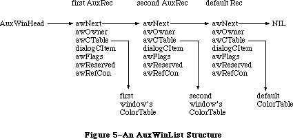 Figure 5–An AuxWinList Structure
The AuxWinRec structure includes a handle to the window’s individual color table (see “Window Color Tables” below), as well as the handle to the dialogCItem list. The rest of the record consists of a link to the next record in the list, a pointer to the owning window, and several reserved fields.
TYPE
AuxWinHandle = ^AuxWinPtr;
AuxWinPtr = ^AuxWinRec;
AuxWinRec = RECORD
awNext: AuxWinHandle; {handle to next record in list}
awOwner: WindowPtr; {pointer to owning window}
awCTable: CTabHandle; {handle to window's color table}
dialogCItem: Handle; {private storage for }
{ Dialog Manager}
awFlags: LONGINT; {reserved for future use}
awReserved: CTabHandle; {reserved for future use}
awRefCon: LONGINT {reserved for }
{ application use}
END;
Field descriptions
awNext The awNext field is a handle to the next record in the auxiliary
window list. If this record is the default auxWinRec, this value
will be NIL.
awOwner The awOwner field is a pointer to the window to which this
record belongs. The default auxWinRec awOwner field is always
set to NIL.
awCTable The awCTable is a handle to the window’s color table. Normally
these are five-element color tables (see “Window Color Tables”
below).
dialogCItem The dialogCItem field contains private storage for the
Dialog Manager.
awFlags The awFlags field is reserved for future expansion.
awReserved The awReserved field is reserved for future expansion.
awRefCon The awRefCon field is a reference constant for use by
the application.
The default colors for all windows are loaded from a 'wctb' resource = 0 when InitWindows is called. First the application is checked for a 'wctb' resource, then if none is found, the System file is checked, and finally, ROM Resources is checked for an existing 'wctb'. To change the default colors for any of the windows, use SetWinColor. The standard colors on the system are identical to black-and-white Macintosh windows.
An AuxWinRec specifies the default colorTable for the application’s window list. For most types of applications, several windows can use the same auxiliary window record and share the same color table. Separate auxiliary window records are needed only for windows whose color usage differs from the default. Each such nonstandard window must have its own auxiliary record, even if it uses the same colors as another window. Two or more auxiliary records may share the same color table. If a window uses a color table resource, the resource must not be purgeable, and the color table won’t be disposed when DisposeWindow is called. However, for an auxiliary record using any color table that is not a resource, the application must avoid deallocating the color table if another window is still using it.
The AuxWinRec is deallocated when DisposeWindow is called. If the resource bit of a color table’s handle is set, the color table can only be disposed using the Resource Manager routine ReleaseResource.
A window created with the NewWindow routine will initially have no auxiliary window record. If it is to use nonstandard colors, it must be given an auxiliary record and a color table with SetWinColor (see the “Window Manager Routines” section). Such a window should normally be made invisible at creation and then displayed with ShowWindow or ShowHide after the colors are set. For windows created from a template resource, the color table can be specified as a resource as well.
A/UX systems: For systems using 32-bit mode, each window will have an
AuxWinRec. The default AuxWinRec structure is present at
the end of the AuxWinList, but is not used. The variant
code for the window is no longer stored in the high byte
of the windowDefProc field, but is stored in the awFlags
field. This allows the defproc to occur anywhere within
the 32-bit address space.
_______________________________________________________________________________
»WINDOW COLOR TABLES
_______________________________________________________________________________
The contents and meaning of a window’s color table are determined by its window definition function (see the “Defining Your Own Windows” section later in this chapter). The CTabHandle parameter used in the Window Manager routines provides a handle to the window color table. The color table containing the window’s colorSpecs can have any number of entries, but standard window color tables as stored in the system resource file have five colorSpecs.
The components of a window color table are defined as follows:
TYPE
WCTabHandle = ^WCTabPtr;
WCTabPtr = ^WinCTab;
WinCTab = RECORD
wCSeed: LONGINT; {unique identifier from table}
wCReserved: INTEGER; {not used for windows}
ctSize: INTEGER; {number of entries in table –1}
ctTable: Array [0..4] of ColorSpec; {array of }
{ ColorSpec records}
END;
Field descriptions
wCSeed The wCSeed field is unused in window color tables, and is
reserved for Apple’s use.
wCReserved The wCReserved field is unused in window color tables, and is
reserved for Apple’s use.
ctSize The ctSize field defines the number of elements in the table,
minus one. If your application is building a color table for
use with the standard definition procedure, this field is always
4. Custom window definition procedures can allocate color tables
of any size.
ctTable The ctTable field is made of an array of colorSpec records.
Each colorSpec contains the partIdentifer and partRGB field,
as shown below. The partIdentifier field holds an integer which
associates a colorSpec to a particular part of the window. The
definition procedures attempt to find the appropriate
partIdentifier when preparing to draw a part. If that
partIdentifier is not found, the first color in the table is
used to draw the part. The partIdentifiers can appear in any
order in the table. The partRGB field specifies a standard RGB
color record, indicating what RGB value will be used to draw
the window part found in partIdentifier.
The standard window type uses a five-element color table with part identifiers as shown in Figure 6.
Figure 5–An AuxWinList Structure
The AuxWinRec structure includes a handle to the window’s individual color table (see “Window Color Tables” below), as well as the handle to the dialogCItem list. The rest of the record consists of a link to the next record in the list, a pointer to the owning window, and several reserved fields.
TYPE
AuxWinHandle = ^AuxWinPtr;
AuxWinPtr = ^AuxWinRec;
AuxWinRec = RECORD
awNext: AuxWinHandle; {handle to next record in list}
awOwner: WindowPtr; {pointer to owning window}
awCTable: CTabHandle; {handle to window's color table}
dialogCItem: Handle; {private storage for }
{ Dialog Manager}
awFlags: LONGINT; {reserved for future use}
awReserved: CTabHandle; {reserved for future use}
awRefCon: LONGINT {reserved for }
{ application use}
END;
Field descriptions
awNext The awNext field is a handle to the next record in the auxiliary
window list. If this record is the default auxWinRec, this value
will be NIL.
awOwner The awOwner field is a pointer to the window to which this
record belongs. The default auxWinRec awOwner field is always
set to NIL.
awCTable The awCTable is a handle to the window’s color table. Normally
these are five-element color tables (see “Window Color Tables”
below).
dialogCItem The dialogCItem field contains private storage for the
Dialog Manager.
awFlags The awFlags field is reserved for future expansion.
awReserved The awReserved field is reserved for future expansion.
awRefCon The awRefCon field is a reference constant for use by
the application.
The default colors for all windows are loaded from a 'wctb' resource = 0 when InitWindows is called. First the application is checked for a 'wctb' resource, then if none is found, the System file is checked, and finally, ROM Resources is checked for an existing 'wctb'. To change the default colors for any of the windows, use SetWinColor. The standard colors on the system are identical to black-and-white Macintosh windows.
An AuxWinRec specifies the default colorTable for the application’s window list. For most types of applications, several windows can use the same auxiliary window record and share the same color table. Separate auxiliary window records are needed only for windows whose color usage differs from the default. Each such nonstandard window must have its own auxiliary record, even if it uses the same colors as another window. Two or more auxiliary records may share the same color table. If a window uses a color table resource, the resource must not be purgeable, and the color table won’t be disposed when DisposeWindow is called. However, for an auxiliary record using any color table that is not a resource, the application must avoid deallocating the color table if another window is still using it.
The AuxWinRec is deallocated when DisposeWindow is called. If the resource bit of a color table’s handle is set, the color table can only be disposed using the Resource Manager routine ReleaseResource.
A window created with the NewWindow routine will initially have no auxiliary window record. If it is to use nonstandard colors, it must be given an auxiliary record and a color table with SetWinColor (see the “Window Manager Routines” section). Such a window should normally be made invisible at creation and then displayed with ShowWindow or ShowHide after the colors are set. For windows created from a template resource, the color table can be specified as a resource as well.
A/UX systems: For systems using 32-bit mode, each window will have an
AuxWinRec. The default AuxWinRec structure is present at
the end of the AuxWinList, but is not used. The variant
code for the window is no longer stored in the high byte
of the windowDefProc field, but is stored in the awFlags
field. This allows the defproc to occur anywhere within
the 32-bit address space.
_______________________________________________________________________________
»WINDOW COLOR TABLES
_______________________________________________________________________________
The contents and meaning of a window’s color table are determined by its window definition function (see the “Defining Your Own Windows” section later in this chapter). The CTabHandle parameter used in the Window Manager routines provides a handle to the window color table. The color table containing the window’s colorSpecs can have any number of entries, but standard window color tables as stored in the system resource file have five colorSpecs.
The components of a window color table are defined as follows:
TYPE
WCTabHandle = ^WCTabPtr;
WCTabPtr = ^WinCTab;
WinCTab = RECORD
wCSeed: LONGINT; {unique identifier from table}
wCReserved: INTEGER; {not used for windows}
ctSize: INTEGER; {number of entries in table –1}
ctTable: Array [0..4] of ColorSpec; {array of }
{ ColorSpec records}
END;
Field descriptions
wCSeed The wCSeed field is unused in window color tables, and is
reserved for Apple’s use.
wCReserved The wCReserved field is unused in window color tables, and is
reserved for Apple’s use.
ctSize The ctSize field defines the number of elements in the table,
minus one. If your application is building a color table for
use with the standard definition procedure, this field is always
4. Custom window definition procedures can allocate color tables
of any size.
ctTable The ctTable field is made of an array of colorSpec records.
Each colorSpec contains the partIdentifer and partRGB field,
as shown below. The partIdentifier field holds an integer which
associates a colorSpec to a particular part of the window. The
definition procedures attempt to find the appropriate
partIdentifier when preparing to draw a part. If that
partIdentifier is not found, the first color in the table is
used to draw the part. The partIdentifiers can appear in any
order in the table. The partRGB field specifies a standard RGB
color record, indicating what RGB value will be used to draw
the window part found in partIdentifier.
The standard window type uses a five-element color table with part identifiers as shown in Figure 6.
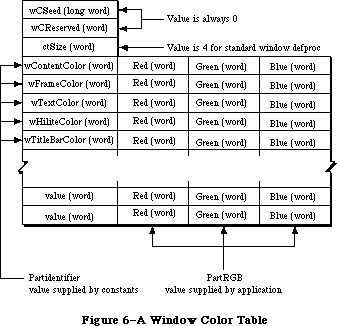 Figure 6–A Window Color Table
The following constants are used for the partIdentifiers in a window color table:
wContentColor = 0;
wFrameColor = 1;
wTextColor = 2;
wHiliteColor = 3;
wTitleBarColor = 4;
The default color table read into the heap at application startup simply contains the right combination of black and white to produce standard
black-and-white Macintosh windows. The last record in the auxiliary window list holds a handle to this default color table. Before drawing a window, the standard window definition function searches the list for an auxiliary record whose awOwner points to the window to be drawn. If it finds such a record, it uses the color table designated by that record; if it doesn’t find one before reaching the default record at the end of the list, it uses the default color table instead. The default record is recognized by NIL values in both its awNext and awOwner fields; your program must not change these fields.
When creating a color window, the background color is set to the content color. Old-style windows should use a content color of white.
A nonstandard window definition function can explicitly declare a color table of any desired size and define its contents in any way it wishes, except that part identifiers 1 to 127 are reserved for system definition. For compatibility with the defaulting mechanism described above, the customized definition function should either use indices 0 to 4 in the standard way, or else bypass the default by allocating an explicit auxiliary record for every window it creates. To access a nonstandard window color table from Pascal, the handle must be coerced to WCTabHandle.
The 'wctb' resource is an exact image of the window table data structure. This resource is stored in a similar format as 'clut' color table resources. The partIdentifier and partCode fields are stored as the colorSpec.value and colorSpec.RGBColor fields.
_______________________________________________________________________________
»HOW A WINDOW IS DRAWN
_______________________________________________________________________________
When a window is drawn or redrawn, the following two-step process usually takes place: The Window Manager draws the window frame, then the application draws the window contents.
To perform the first step of this process, the Window Manager calls the window definition function with a request that the window frame be drawn. It manipulates regions of the Window Manager port as necessary before calling the window definition function, to ensure that only what should and must be drawn is actually drawn on the screen. Depending on a parameter passed to the routine that created the window, the window definition function may or may not draw a go-away region in the window frame (a close box in the title bar, for a document window).
Usually the second step is that the Window Manager generates an update event to get the application to draw the window contents. It does this by accumulating in the update region the areas of the window’s content region that need updating. The Toolbox Event Manager periodically checks to see if there’s any window whose update region is not empty; if it finds one, it reports (via the GetNextEvent function) that an update event has occurred, and passes along the window pointer in the event message. (If it finds more than one such window, it issues an update event for the frontmost one, so that update events are reported in front-to-back order.) The application should respond as follows:
1. Call BeginUpdate. This procedure temporarily replaces the visRgn of
the window’s grafPort with the intersection of the visRgn and the
update region. It then sets the update region to an empty region;
this “clears” the update event so it won’t be reported again.
2. Draw the window contents, entirely or in part. Normally it’s more
convenient to draw the entire content region, but it suffices to
draw only the visRgn. In either case, since the visRgn is limited
to where it intersects the old update region, only the parts of the
window that require updating will actually be drawn on the screen.
3. Call EndUpdate, which restores the normal visRgn.
Figure 7 illustrates the effect of BeginUpdate and EndUpdate on the visRgn and update region of a window that’s redrawn after being brought to the front.
If you choose to draw only the visRgn in step 2, there are various ways you can check to see whether what you need to draw falls in that region. With the QuickDraw function PtInRgn, you can check whether a point lies in the visRgn. It may be more convenient to look at the visRgn’s enclosing rectangle, which is stored in its rgnBBox field. The QuickDraw functions PtInRect and SectRect let you check for intersection with a rectangle.
To be able to respond to update events for one of its windows, the application has to keep track of the window’s contents, usually in a data structure. In most cases, it’s best never to draw immediately into a window; when you need to draw something, just keep track of it and add the area where it should be drawn to the window’s update region (by calling one of the Window Manager’s update region maintenance routines, InvalRect and InvalRgn). Do the actual drawing only in response to an update event. Usually this will simplify the structure of your application considerably, but be aware of the following possible problems:
• This method doesn’t work if you want to do continuous scrolling while
the user presses a scroll arrow; in this case, you would draw directly
into the window.
• This method isn’t convenient to apply to areas that aren’t easily
defined by a rectangle or a region; again, just draw directly into the
window.
• If you find that sometimes there’s too long a delay before an update
event happens, you can get update events first when necessary by
calling GetNextEvent with a mask that accepts only that type of event.
The Window Manager allows an alternative to the update event mechanism that may be useful for windows whose contents never change: A handle to a QuickDraw picture may be stored in the window record. If this is done, the Window Manager doesn’t generate an update event to get the application to draw the window contents; instead, it calls the QuickDraw procedure DrawPicture to draw the picture whose handle is stored in the window record (and it does all the necessary region manipulation).
Figure 6–A Window Color Table
The following constants are used for the partIdentifiers in a window color table:
wContentColor = 0;
wFrameColor = 1;
wTextColor = 2;
wHiliteColor = 3;
wTitleBarColor = 4;
The default color table read into the heap at application startup simply contains the right combination of black and white to produce standard
black-and-white Macintosh windows. The last record in the auxiliary window list holds a handle to this default color table. Before drawing a window, the standard window definition function searches the list for an auxiliary record whose awOwner points to the window to be drawn. If it finds such a record, it uses the color table designated by that record; if it doesn’t find one before reaching the default record at the end of the list, it uses the default color table instead. The default record is recognized by NIL values in both its awNext and awOwner fields; your program must not change these fields.
When creating a color window, the background color is set to the content color. Old-style windows should use a content color of white.
A nonstandard window definition function can explicitly declare a color table of any desired size and define its contents in any way it wishes, except that part identifiers 1 to 127 are reserved for system definition. For compatibility with the defaulting mechanism described above, the customized definition function should either use indices 0 to 4 in the standard way, or else bypass the default by allocating an explicit auxiliary record for every window it creates. To access a nonstandard window color table from Pascal, the handle must be coerced to WCTabHandle.
The 'wctb' resource is an exact image of the window table data structure. This resource is stored in a similar format as 'clut' color table resources. The partIdentifier and partCode fields are stored as the colorSpec.value and colorSpec.RGBColor fields.
_______________________________________________________________________________
»HOW A WINDOW IS DRAWN
_______________________________________________________________________________
When a window is drawn or redrawn, the following two-step process usually takes place: The Window Manager draws the window frame, then the application draws the window contents.
To perform the first step of this process, the Window Manager calls the window definition function with a request that the window frame be drawn. It manipulates regions of the Window Manager port as necessary before calling the window definition function, to ensure that only what should and must be drawn is actually drawn on the screen. Depending on a parameter passed to the routine that created the window, the window definition function may or may not draw a go-away region in the window frame (a close box in the title bar, for a document window).
Usually the second step is that the Window Manager generates an update event to get the application to draw the window contents. It does this by accumulating in the update region the areas of the window’s content region that need updating. The Toolbox Event Manager periodically checks to see if there’s any window whose update region is not empty; if it finds one, it reports (via the GetNextEvent function) that an update event has occurred, and passes along the window pointer in the event message. (If it finds more than one such window, it issues an update event for the frontmost one, so that update events are reported in front-to-back order.) The application should respond as follows:
1. Call BeginUpdate. This procedure temporarily replaces the visRgn of
the window’s grafPort with the intersection of the visRgn and the
update region. It then sets the update region to an empty region;
this “clears” the update event so it won’t be reported again.
2. Draw the window contents, entirely or in part. Normally it’s more
convenient to draw the entire content region, but it suffices to
draw only the visRgn. In either case, since the visRgn is limited
to where it intersects the old update region, only the parts of the
window that require updating will actually be drawn on the screen.
3. Call EndUpdate, which restores the normal visRgn.
Figure 7 illustrates the effect of BeginUpdate and EndUpdate on the visRgn and update region of a window that’s redrawn after being brought to the front.
If you choose to draw only the visRgn in step 2, there are various ways you can check to see whether what you need to draw falls in that region. With the QuickDraw function PtInRgn, you can check whether a point lies in the visRgn. It may be more convenient to look at the visRgn’s enclosing rectangle, which is stored in its rgnBBox field. The QuickDraw functions PtInRect and SectRect let you check for intersection with a rectangle.
To be able to respond to update events for one of its windows, the application has to keep track of the window’s contents, usually in a data structure. In most cases, it’s best never to draw immediately into a window; when you need to draw something, just keep track of it and add the area where it should be drawn to the window’s update region (by calling one of the Window Manager’s update region maintenance routines, InvalRect and InvalRgn). Do the actual drawing only in response to an update event. Usually this will simplify the structure of your application considerably, but be aware of the following possible problems:
• This method doesn’t work if you want to do continuous scrolling while
the user presses a scroll arrow; in this case, you would draw directly
into the window.
• This method isn’t convenient to apply to areas that aren’t easily
defined by a rectangle or a region; again, just draw directly into the
window.
• If you find that sometimes there’s too long a delay before an update
event happens, you can get update events first when necessary by
calling GetNextEvent with a mask that accepts only that type of event.
The Window Manager allows an alternative to the update event mechanism that may be useful for windows whose contents never change: A handle to a QuickDraw picture may be stored in the window record. If this is done, the Window Manager doesn’t generate an update event to get the application to draw the window contents; instead, it calls the QuickDraw procedure DrawPicture to draw the picture whose handle is stored in the window record (and it does all the necessary region manipulation).
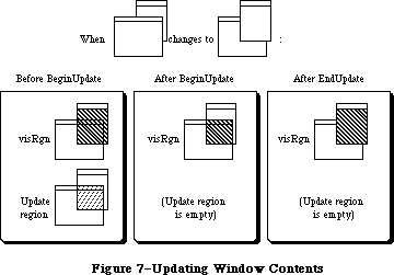 Figure 7–Updating Window Contents
_______________________________________________________________________________
»MAKING A WINDOW ACTIVE: ACTIVATE EVENTS
_______________________________________________________________________________
A number of Window Manager routines change the state of a window from inactive to active or from active to inactive. For each such change, the Window Manager generates an activate event, passing along the window pointer in the event message. The activeFlag bit in the modifiers field of the event record is set if the window has become active, or cleared if it has become inactive.
When the Toolbox Event Manager finds out from the Window Manager that an activate event has been generated, it passes the event on to the application
(via the GetNextEvent function). Activate events have the highest priority of any type of event.
Usually when one window becomes active another becomes inactive, and vice versa, so activate events are most commonly generated in pairs. When this happens, the Window Manager generates first the event for the window becoming inactive, and then the event for the window becoming active. Sometimes only a single activate event is generated, such as when there’s only one window in the window list, or when the active window is permanently disposed of (since it no longer exists).
Activate events for dialog and alert windows are handled by the Dialog Manager. In response to activate events for windows created directly by your application, you might take actions such as the following:
• In a document window containing a size box or scroll bars, erase the
size box icon or scroll bars when the window becomes inactive and
redraw them when it becomes active.
• In a window that contains text being edited, remove the highlighting
or blinking vertical bar from the text when the window becomes inactive
and restore it when the window becomes active.
• Enable or disable a menu or certain menu items as appropriate to match
what the user can do when the window becomes active or inactive.
Assembly-language note: The global variable CurActivate contains a
pointer to a window for which an activate event
has been generated; the event, however, may not
yet have been reported to the application via
GetNextEvent, so you may be able to keep the event
from happening by clearing CurActivate. Similarly,
you may be able to keep a deactivate event from
happening by clearing the global variable CurDeactive.
_______________________________________________________________________________
»USING THE WINDOW MANAGER
_______________________________________________________________________________
To use the Window Manager, you must have previously called InitGraf to initialize QuickDraw and InitFonts to initialize the Font Manager. The first Window Manager routine to call is the initialization routine InitWindows, which draws the desktop and the (empty) menu bar.
Where appropriate in your program, use NewWindow or GetNewWindow to create any windows you need; these functions return a window pointer, which you can then use to refer to the window. NewWindow takes descriptive information about the window from its parameters, whereas GetNewWindow gets the information from a window template in a resource file. You can supply a pointer to the storage for the window record or let it be allocated by the routine creating the window; when you no longer need a window, call CloseWindow if you supplied the storage, or DisposeWindow if not.
When the Toolbox Event Manager function GetNextEvent reports that an update event has occurred, call BeginUpdate, draw the visRgn or the entire content region, and call EndUpdate (see “How a Window is Drawn”). You can also use InvalRect or InvalRgn to prepare a window for updating, and ValidRect or ValidRgn to protect portions of the window from updating.
When drawing the contents of a window that contains a size box in its content region, you’ll draw the size box if the window is active or just the lines delimiting the size box and scroll bar areas if it’s inactive. The FrontWindow function tells you which is the active window; the DrawGrowIcon procedure helps you draw the size box or delimiting lines. You’ll also call the latter procedure when an activate event occurs that makes the window active or inactive.
Note: Before drawing in a window or making a call that affects the update
region, remember to set the window to be the current grafPort with
the QuickDraw procedure SetPort.
When GetNextEvent reports a mouse-down event, call the FindWindow function to find out which part of which window the mouse button was pressed in.
• If it was pressed in the content region of an inactive window, make
that window the active window by calling SelectWindow.
• If it was pressed in the grow region of the active window, call
GrowWindow to pull around an image that shows how the window’s size
will change, and then SizeWindow to actually change the size.
• If it was pressed in the drag region of any window, call DragWindow,
which will pull an outline of the window across the screen, move the
window to a new location, and, if the window is inactive, make it the
active window (unless the Command key was held down).
• If it was pressed in the go-away region of the active window, call
TrackGoAway to handle the highlighting of the go-away region and to
determine whether the mouse is inside the region when the button is
released. Then do whatever is appropriate as a response to this mouse
action in the particular application. For example, call CloseWindow or
DisposeWindow if you want the window to go away permanently, or
HideWindow if you want it to disappear temporarily.
Note: If the mouse button was pressed in the content region of an
active window (but not in the grow region), call the Control
Manager function FindControl if the window contains controls.
If it was pressed in a system window, call the Desk Manager
procedure SystemClick. See the Control Manager and Desk Manager
chapters for details.
The MoveWindow procedure simply moves a window without pulling around an outline of it. Note, however, that the application shouldn’t surprise the user by moving (or sizing) windows unexpectedly. There are other routines that you normally won’t need to use that let you change the title of a window, place one window behind another, make a window visible or invisible, and access miscellaneous fields of the window record. There are also low-level routines that may be of interest to advanced programmers.
A new variation of the window definition function implements a feature known as window zooming; a description of window zooming is found in the Macintosh User Interface Guidelines chapter.
If you’re using the standard document window, you can implement a zoom-window box by specifying a window definition function with a resource ID of 0 and a variation code of 8 when you call either the NewWindow or GetNewWindow functions. Two fields in the window record, dataHandle and spareFlag, are used only when variation code 8 is specified (otherwise they’re not used).
DataHandle contains a handle to two rectangles that specify the standard and user states of the window:
TYPE
WStateData = RECORD;
userState: Rect;
stdState: Rect
END;
If you wish, your application can access both states. You might want to provide initial values for the user state. Or you might want to save and restore all windows to the same state the next time your application is launched. To do this, you would save the two states and determine which of the two is current. The next time the application is launched, you would then create the window using the saved current state, and set the user and standard states to their previous values, after the GetNewWindow or NewWindow call.
SpareFlag is TRUE if zooming has been requested (that is, if a variation code of 8 has been specified).
If you create a custom window, you can give your window definition function any variation code you wish. If you want to implement zooming in the custom window, you must supply values for WStateData.
When there’s a mouse-down event in the zoom-window box and your application calls the FindWindow function, the integer returned will be one of the following predefined constants:
CONST inZoomIn = 7; {in zoom box for zooming in}
inZoomOut = 8; {in zoom box for zooming out}
InZoomIn and inZoomOut both indicate that the mouse button was pressed in the zoom-window box of the window. FindWindow returns inZoomIn when the window is in the standard state (and will be zoomed in), and inZoomOut when it’s in the user state (and will be zoomed out).
If either of these constants are returned by FindWindow, call the TrackBox function (described below) to handle the highlighting of the zoom-window box and to determine whether the mouse is inside the box when the button is released. If TrackBox returns TRUE, call the ZoomWindow procedure (described below) to resize the window appropriately.
Advanced programmers: Two additional constants have been defined for your
window definition function to return in response to
a wHit message:
CONST wInZoomIn = 5; {in zoom box for zooming in}
wInZoomOut = 6; {in zoom box for zooming out}
_______________________________________________________________________________
»USING COLOR WINDOWS
_______________________________________________________________________________
Each color window (excluding those using a colored default) should have its own color table. When an application is initialized, the default colorTable field used is the 'wctb' resource = 0 in the application’s resource fork. This allows you to set default window colors on an application basis. If a 'wctb'
resource = 0 is not found in the application, or in the System file, a nonchangeable resource is loaded from ROM resources. Normally, the default window colors will be the correct combination of black and white to create standard Macintosh windows.
The GetAuxWin routine is used to return the handle to an individual window color table. CloseWindow will dispose of a window’s AuxWinRec, if present.
When a new window is created with the NewCWindow or NewWindow routine, no entry is added to the AuxList, and the window will use the default colors. If SetWinColor is used with a different color table for a window, a new AuxList will be allocated and added to the head of the list. To avoid having a visible window flash to a different color, it is useful to call NewCWindow or NewWindow with the visible field set to FALSE, then to call SetWinColor to change the colors, and finally to call ShowHide to make it visible.
Within an application, a new window is usually created from a resource by using GetNewCWindow or GetNewWindow. GetNewCWindow will attempt to load a 'wctb' resource if it is present. It then executes the SetWinColor call. A new AuxRec is allocated if the resource file contains the 'wctb' resource with the same ResId as the 'WIND' template. Otherwise, the default window colors are used. The Window Manager automatically hides specially-colored visible windows so that they won’t flash to a different color.
Any windows created with NewWindow will contain an old-style grafPort in the windowRec, and only the eight original QuickDraw colors can be displayed in the window content. NewCWindow creates a window record based on a cGrafport, thus allowing full use of the Macintosh II color capability.
Advanced Window Manager routines include SetDeskCPat, which allows the Control Panel to set the desktop pattern to a color pattern. This routine should not be used in application programs, but its description here will help you understand how the Window Manager manages desktop patterns. The GetCWMgrPort routine returns the address of the WMgrCPort. In most cases this won’t be necessary, since applications should avoid drawing in the Window Manager ports.
Color QuickDraw on the Macintosh II supports drawing to multiple screens that have been configured to act as a single large screen. All window dragging and sizing operations, including the MoveWindow, DragGrayRgn, GrowWindow, SizeWindow, and ZoomWindow routines, have been modified to allow windows to perform properly when dragged across a multiple-screen desktop. If a portion of a window moves across screen boundaries, update events are automatically generated to ensure that the window’s contents are drawn in the correct colors.
A special Window Manager variable, the GrayRgn, describes the size and shape of the desktop on all Macintoshes. On a multiple-screen Macintosh II, the GrayRgn variable contains information on all the screens configured into the system. Your application can determine the size of the desktop by checking the
GrayRgn’s bounding box, and should use this rectangle for dragging and sizing bounds. The GetGrayRgn routine returns a handle to the current desktop GrayRgn. Zooming should be restricted to using the full size of only one screen by using screenbits.bounds for the main screen, or the appropriate GDRect for any other screens.
_______________________________________________________________________________
»WINDOW MANAGER ROUTINES
_______________________________________________________________________________
»Initialization and Allocation
PROCEDURE InitWindows; [Macintosh Plus, Macintosh SE, Macintosh II]
InitWindows initializes the Window Manager. It creates the Window Manager port; you can get a pointer to this port with the GetWMgrPort procedure. InitWindows draws the desktop (as a rounded-corner rectangle with diameters of curvature 16,16, in the desktop pattern) and the (empty) menu bar. Call this procedure once before all other Window Manager routines.
Note: The desktop pattern is the pattern whose resource ID is:
CONST deskPatID = 16;
If you store a pattern with resource ID deskPatID in the application’s
resource file, that pattern will be used whenever the desktop is drawn.
The InitWindow procedure now calls the new Menu Bar definition procedure to calculate menu bar height, and to draw the empty menu bar. Since the menu bar definition procedure ('MBDF') actually performs these calculations, InitWindows now calls InitMenus directly. InitMenus has been modified so that it can be called twice in a program without ill effect.
For the Macintosh II, if the color desktop pattern is enabled, InitWindows loads the default desktop pixel pattern as well as the standard binary pattern. It allocates both the WMgrCPort and the WMgrPort, then calculates the union of all active screen devices, and saves this region in the global variable GrayRgn.
Warning: InitWindows creates the Window Manager port as a nonrelocatable
block in the application heap. To prevent heap fragmentation,
call InitWindows in the main segment of your program, before any
references to routines in other segments.
Assembly-language note: InitWindows initializes the global variable GrayRgn
to be a handle to the desktop region (a rounded-corner
rectangle occupying the entire screen, minus the menu
bar), and draws this region. It initializes the global
variable DeskPattern to the pattern whose resource ID
is deskPatID, and paints the desktop with this pattern.
Any subsequent time that the desktop needs to be drawn,
such as when a new area of it is exposed after a
window is closed or moved, the Window Manager calls
the procedure pointed to by the global variable
DeskHook, if any (normally DeskHook is 0). The
DeskHook procedure is called with 0 in register D0
to distinguish this use of it from its use in
responding to clicks on the desktop (discussed in the
description of FindWindow); it should respond by
painting thePort^.clipRgn with DeskPattern and then
doing anything else it wants.
PROCEDURE GetWMgrPort (VAR wPort: GrafPtr);
GetWMgrPort returns in wPort a pointer to the Window Manager port.
Warning: Do not change any regions of the Window Manager port, or
overlapping windows may not be handled properly.
Assembly-language note: This pointer is stored in the global variable
WMgrPort.
FUNCTION NewWindow (wStorage: Ptr; boundsRect: Rect; title: Str255;
visible: BOOLEAN; procID: INTEGER; behind: WindowPtr;
goAwayFlag: BOOLEAN; refCon: LONGINT) : WindowPtr;
NewWindow creates a window as specified by its parameters, adds it to the window list, and returns a windowPtr to the new window. It allocates space for the structure and content regions of the window and asks the window definition function to calculate those regions.
WStorage is a pointer to where to store the window record. For example, if
you’ve declared the variable wRecord of type WindowRecord, you can pass @wRecord as the first parameter to NewWindow. If you pass NIL for wStorage, the window record will be allocated as a nonrelocatable object in the heap; in that case, though, you risk ending up with a fragmented heap.
BoundsRect, a rectangle given in global coordinates, determines the window’s size and location, and becomes the portRect of the window’s grafPort; note, however, that the portRect is in local coordinates. NewWindow sets the top left corner of the portRect to (0,0). For the standard types of windows, the boundsRect defines the content region of the window.
Note: The bit map, pen pattern, and other characteristics of the window’s
grafPort are the same as the default values set by the OpenPort
procedure in QuickDraw, except for the character font, which is set
to the application font rather than the system font. (NewWindow
actually calls OpenPort to initialize the window’s grafPort.) Note,
however, that the coordinates of the grafPort’s portBits.bounds and
visRgn are changed along with its portRect.
The title parameter is the window’s title. If the title of a document window is longer than will fit in the title bar, it’s truncated in one of two ways: If the window has a close box, the characters that don’t fit are truncated from the end of the title; if there’s no close box, the title is centered and truncated at both ends.
If the visible parameter is TRUE, NewWindow draws the window. First it calls the window definition function to draw the window frame; if goAwayFlag is also TRUE and the window is frontmost (as specified by the behind parameter, below), it draws a go-away region in the frame. Then it generates an update event for the entire window contents.
ProcID is the window definition ID, which leads to the window definition function for this type of window. The function is read into memory if it’s not already in memory. If it can’t be read, NewWindow returns NIL. The window definition IDs for the standard types of windows are listed above under
“Windows and Resources”. Window definition IDs for windows of your own design are discussed later under “Defining Your Own Windows”.
The behind parameter determines the window’s plane. The new window is inserted in back of the window pointed to by this parameter. To put the new window behind all other windows, use behind=NIL. To place it in front of all other windows, use behind=POINTER(–1); in this case, NewWindow will unhighlight the previously active window, highlight the window being created, and generate appropriate activate events.
RefCon is the window’s reference value, set and used only by your application.
NewWindow also sets the window class in the window record to indicate that the window was created directly by the application.
FUNCTION GetNewWindow (windowID: INTEGER; wStorage: Ptr;
behind: WindowPtr) : WindowPtr;
Like NewWindow (above), GetNewWindow creates a window as specified by its parameters, adds it to the window list, and returns a windowPtr to the new window. The only difference between the two functions is that instead of having the parameters boundsRect, title, visible, procID, goAwayFlag, and refCon, GetNewWindow has a single windowID parameter, where windowID is the resource ID of a window template that supplies the same information as those parameters. If the window template can’t be read from the resource file, GetNewWindow returns NIL. GetNewWindow releases the memory occupied by the resource before returning. The wStorage and behind parameters have the same meaning as in NewWindow.
PROCEDURE CloseWindow (theWindow: WindowPtr);
CloseWindow removes the given window from the screen and deletes it from the window list. It releases the memory occupied by all data structures associated with the window, but not the memory taken up by the window record itself. Call this procedure when you’re done with a window if you supplied NewWindow or GetNewWindow a pointer to the window storage (in the wStorage parameter) when you created the window.
Any update events for the window are discarded. If the window was the frontmost window and there was another window behind it, the latter window is highlighted and an appropriate activate event is generated.
Warning: If you allocated memory yourself and stored a handle to it in the
refCon field, CloseWindow won’t know about it—you must release the
memory before calling CloseWindow. Similarly, if you used the
windowPic field to access a picture stored as a resource, you must
release the memory it occupies; CloseWindow assumes the picture
isn’t a resource, and calls the QuickDraw procedure KillPicture to
delete it.
PROCEDURE DisposeWindow (theWindow: WindowPtr);
Assembly-language note: The macro you invoke to call DisposeWindow from
assembly language is named _DisposWindow.
Dispose Window calls CloseWindow (above) and then releases the memory occupied by the window record. Call this procedure when you’re done with a window if you let the window record be allocated in the heap when you created the window (by passing NIL as the wStorage parameter to NewWindow or GetNewWindow).
_______________________________________________________________________________
»Window Display
These procedures affect the appearance or plane of a window but not its size or location.
PROCEDURE SetWTitle (theWindow: WindowPtr; title: Str255);
SetWTitle sets theWindow’s title to the given string, performing any necessary redrawing of the window frame.
PROCEDURE GetWTitle (theWindow: WindowPtr; VAR title: Str255);
GetWTitle returns theWindow's title as the value of the title parameter.
PROCEDURE SelectWindow (theWindow: WindowPtr);
SelectWindow makes theWindow the active window as follows: It unhighlights the previously active window, brings theWindow in front of all other windows, highlights theWindow, and generates the appropriate activate events. Call this procedure if there’s a mouse-down event in the content region of an inactive window.
PROCEDURE HideWindow (theWindow: WindowPtr);
HideWindow makes theWindow invisible. If theWindow is the frontmost window and there’s a window behind it, HideWindow also unhighlights theWindow, brings the window behind it to the front, highlights that window, and generates appropriate activate events (see Figure 8). If theWindow is already invisible, HideWindow has no effect.
Figure 7–Updating Window Contents
_______________________________________________________________________________
»MAKING A WINDOW ACTIVE: ACTIVATE EVENTS
_______________________________________________________________________________
A number of Window Manager routines change the state of a window from inactive to active or from active to inactive. For each such change, the Window Manager generates an activate event, passing along the window pointer in the event message. The activeFlag bit in the modifiers field of the event record is set if the window has become active, or cleared if it has become inactive.
When the Toolbox Event Manager finds out from the Window Manager that an activate event has been generated, it passes the event on to the application
(via the GetNextEvent function). Activate events have the highest priority of any type of event.
Usually when one window becomes active another becomes inactive, and vice versa, so activate events are most commonly generated in pairs. When this happens, the Window Manager generates first the event for the window becoming inactive, and then the event for the window becoming active. Sometimes only a single activate event is generated, such as when there’s only one window in the window list, or when the active window is permanently disposed of (since it no longer exists).
Activate events for dialog and alert windows are handled by the Dialog Manager. In response to activate events for windows created directly by your application, you might take actions such as the following:
• In a document window containing a size box or scroll bars, erase the
size box icon or scroll bars when the window becomes inactive and
redraw them when it becomes active.
• In a window that contains text being edited, remove the highlighting
or blinking vertical bar from the text when the window becomes inactive
and restore it when the window becomes active.
• Enable or disable a menu or certain menu items as appropriate to match
what the user can do when the window becomes active or inactive.
Assembly-language note: The global variable CurActivate contains a
pointer to a window for which an activate event
has been generated; the event, however, may not
yet have been reported to the application via
GetNextEvent, so you may be able to keep the event
from happening by clearing CurActivate. Similarly,
you may be able to keep a deactivate event from
happening by clearing the global variable CurDeactive.
_______________________________________________________________________________
»USING THE WINDOW MANAGER
_______________________________________________________________________________
To use the Window Manager, you must have previously called InitGraf to initialize QuickDraw and InitFonts to initialize the Font Manager. The first Window Manager routine to call is the initialization routine InitWindows, which draws the desktop and the (empty) menu bar.
Where appropriate in your program, use NewWindow or GetNewWindow to create any windows you need; these functions return a window pointer, which you can then use to refer to the window. NewWindow takes descriptive information about the window from its parameters, whereas GetNewWindow gets the information from a window template in a resource file. You can supply a pointer to the storage for the window record or let it be allocated by the routine creating the window; when you no longer need a window, call CloseWindow if you supplied the storage, or DisposeWindow if not.
When the Toolbox Event Manager function GetNextEvent reports that an update event has occurred, call BeginUpdate, draw the visRgn or the entire content region, and call EndUpdate (see “How a Window is Drawn”). You can also use InvalRect or InvalRgn to prepare a window for updating, and ValidRect or ValidRgn to protect portions of the window from updating.
When drawing the contents of a window that contains a size box in its content region, you’ll draw the size box if the window is active or just the lines delimiting the size box and scroll bar areas if it’s inactive. The FrontWindow function tells you which is the active window; the DrawGrowIcon procedure helps you draw the size box or delimiting lines. You’ll also call the latter procedure when an activate event occurs that makes the window active or inactive.
Note: Before drawing in a window or making a call that affects the update
region, remember to set the window to be the current grafPort with
the QuickDraw procedure SetPort.
When GetNextEvent reports a mouse-down event, call the FindWindow function to find out which part of which window the mouse button was pressed in.
• If it was pressed in the content region of an inactive window, make
that window the active window by calling SelectWindow.
• If it was pressed in the grow region of the active window, call
GrowWindow to pull around an image that shows how the window’s size
will change, and then SizeWindow to actually change the size.
• If it was pressed in the drag region of any window, call DragWindow,
which will pull an outline of the window across the screen, move the
window to a new location, and, if the window is inactive, make it the
active window (unless the Command key was held down).
• If it was pressed in the go-away region of the active window, call
TrackGoAway to handle the highlighting of the go-away region and to
determine whether the mouse is inside the region when the button is
released. Then do whatever is appropriate as a response to this mouse
action in the particular application. For example, call CloseWindow or
DisposeWindow if you want the window to go away permanently, or
HideWindow if you want it to disappear temporarily.
Note: If the mouse button was pressed in the content region of an
active window (but not in the grow region), call the Control
Manager function FindControl if the window contains controls.
If it was pressed in a system window, call the Desk Manager
procedure SystemClick. See the Control Manager and Desk Manager
chapters for details.
The MoveWindow procedure simply moves a window without pulling around an outline of it. Note, however, that the application shouldn’t surprise the user by moving (or sizing) windows unexpectedly. There are other routines that you normally won’t need to use that let you change the title of a window, place one window behind another, make a window visible or invisible, and access miscellaneous fields of the window record. There are also low-level routines that may be of interest to advanced programmers.
A new variation of the window definition function implements a feature known as window zooming; a description of window zooming is found in the Macintosh User Interface Guidelines chapter.
If you’re using the standard document window, you can implement a zoom-window box by specifying a window definition function with a resource ID of 0 and a variation code of 8 when you call either the NewWindow or GetNewWindow functions. Two fields in the window record, dataHandle and spareFlag, are used only when variation code 8 is specified (otherwise they’re not used).
DataHandle contains a handle to two rectangles that specify the standard and user states of the window:
TYPE
WStateData = RECORD;
userState: Rect;
stdState: Rect
END;
If you wish, your application can access both states. You might want to provide initial values for the user state. Or you might want to save and restore all windows to the same state the next time your application is launched. To do this, you would save the two states and determine which of the two is current. The next time the application is launched, you would then create the window using the saved current state, and set the user and standard states to their previous values, after the GetNewWindow or NewWindow call.
SpareFlag is TRUE if zooming has been requested (that is, if a variation code of 8 has been specified).
If you create a custom window, you can give your window definition function any variation code you wish. If you want to implement zooming in the custom window, you must supply values for WStateData.
When there’s a mouse-down event in the zoom-window box and your application calls the FindWindow function, the integer returned will be one of the following predefined constants:
CONST inZoomIn = 7; {in zoom box for zooming in}
inZoomOut = 8; {in zoom box for zooming out}
InZoomIn and inZoomOut both indicate that the mouse button was pressed in the zoom-window box of the window. FindWindow returns inZoomIn when the window is in the standard state (and will be zoomed in), and inZoomOut when it’s in the user state (and will be zoomed out).
If either of these constants are returned by FindWindow, call the TrackBox function (described below) to handle the highlighting of the zoom-window box and to determine whether the mouse is inside the box when the button is released. If TrackBox returns TRUE, call the ZoomWindow procedure (described below) to resize the window appropriately.
Advanced programmers: Two additional constants have been defined for your
window definition function to return in response to
a wHit message:
CONST wInZoomIn = 5; {in zoom box for zooming in}
wInZoomOut = 6; {in zoom box for zooming out}
_______________________________________________________________________________
»USING COLOR WINDOWS
_______________________________________________________________________________
Each color window (excluding those using a colored default) should have its own color table. When an application is initialized, the default colorTable field used is the 'wctb' resource = 0 in the application’s resource fork. This allows you to set default window colors on an application basis. If a 'wctb'
resource = 0 is not found in the application, or in the System file, a nonchangeable resource is loaded from ROM resources. Normally, the default window colors will be the correct combination of black and white to create standard Macintosh windows.
The GetAuxWin routine is used to return the handle to an individual window color table. CloseWindow will dispose of a window’s AuxWinRec, if present.
When a new window is created with the NewCWindow or NewWindow routine, no entry is added to the AuxList, and the window will use the default colors. If SetWinColor is used with a different color table for a window, a new AuxList will be allocated and added to the head of the list. To avoid having a visible window flash to a different color, it is useful to call NewCWindow or NewWindow with the visible field set to FALSE, then to call SetWinColor to change the colors, and finally to call ShowHide to make it visible.
Within an application, a new window is usually created from a resource by using GetNewCWindow or GetNewWindow. GetNewCWindow will attempt to load a 'wctb' resource if it is present. It then executes the SetWinColor call. A new AuxRec is allocated if the resource file contains the 'wctb' resource with the same ResId as the 'WIND' template. Otherwise, the default window colors are used. The Window Manager automatically hides specially-colored visible windows so that they won’t flash to a different color.
Any windows created with NewWindow will contain an old-style grafPort in the windowRec, and only the eight original QuickDraw colors can be displayed in the window content. NewCWindow creates a window record based on a cGrafport, thus allowing full use of the Macintosh II color capability.
Advanced Window Manager routines include SetDeskCPat, which allows the Control Panel to set the desktop pattern to a color pattern. This routine should not be used in application programs, but its description here will help you understand how the Window Manager manages desktop patterns. The GetCWMgrPort routine returns the address of the WMgrCPort. In most cases this won’t be necessary, since applications should avoid drawing in the Window Manager ports.
Color QuickDraw on the Macintosh II supports drawing to multiple screens that have been configured to act as a single large screen. All window dragging and sizing operations, including the MoveWindow, DragGrayRgn, GrowWindow, SizeWindow, and ZoomWindow routines, have been modified to allow windows to perform properly when dragged across a multiple-screen desktop. If a portion of a window moves across screen boundaries, update events are automatically generated to ensure that the window’s contents are drawn in the correct colors.
A special Window Manager variable, the GrayRgn, describes the size and shape of the desktop on all Macintoshes. On a multiple-screen Macintosh II, the GrayRgn variable contains information on all the screens configured into the system. Your application can determine the size of the desktop by checking the
GrayRgn’s bounding box, and should use this rectangle for dragging and sizing bounds. The GetGrayRgn routine returns a handle to the current desktop GrayRgn. Zooming should be restricted to using the full size of only one screen by using screenbits.bounds for the main screen, or the appropriate GDRect for any other screens.
_______________________________________________________________________________
»WINDOW MANAGER ROUTINES
_______________________________________________________________________________
»Initialization and Allocation
PROCEDURE InitWindows; [Macintosh Plus, Macintosh SE, Macintosh II]
InitWindows initializes the Window Manager. It creates the Window Manager port; you can get a pointer to this port with the GetWMgrPort procedure. InitWindows draws the desktop (as a rounded-corner rectangle with diameters of curvature 16,16, in the desktop pattern) and the (empty) menu bar. Call this procedure once before all other Window Manager routines.
Note: The desktop pattern is the pattern whose resource ID is:
CONST deskPatID = 16;
If you store a pattern with resource ID deskPatID in the application’s
resource file, that pattern will be used whenever the desktop is drawn.
The InitWindow procedure now calls the new Menu Bar definition procedure to calculate menu bar height, and to draw the empty menu bar. Since the menu bar definition procedure ('MBDF') actually performs these calculations, InitWindows now calls InitMenus directly. InitMenus has been modified so that it can be called twice in a program without ill effect.
For the Macintosh II, if the color desktop pattern is enabled, InitWindows loads the default desktop pixel pattern as well as the standard binary pattern. It allocates both the WMgrCPort and the WMgrPort, then calculates the union of all active screen devices, and saves this region in the global variable GrayRgn.
Warning: InitWindows creates the Window Manager port as a nonrelocatable
block in the application heap. To prevent heap fragmentation,
call InitWindows in the main segment of your program, before any
references to routines in other segments.
Assembly-language note: InitWindows initializes the global variable GrayRgn
to be a handle to the desktop region (a rounded-corner
rectangle occupying the entire screen, minus the menu
bar), and draws this region. It initializes the global
variable DeskPattern to the pattern whose resource ID
is deskPatID, and paints the desktop with this pattern.
Any subsequent time that the desktop needs to be drawn,
such as when a new area of it is exposed after a
window is closed or moved, the Window Manager calls
the procedure pointed to by the global variable
DeskHook, if any (normally DeskHook is 0). The
DeskHook procedure is called with 0 in register D0
to distinguish this use of it from its use in
responding to clicks on the desktop (discussed in the
description of FindWindow); it should respond by
painting thePort^.clipRgn with DeskPattern and then
doing anything else it wants.
PROCEDURE GetWMgrPort (VAR wPort: GrafPtr);
GetWMgrPort returns in wPort a pointer to the Window Manager port.
Warning: Do not change any regions of the Window Manager port, or
overlapping windows may not be handled properly.
Assembly-language note: This pointer is stored in the global variable
WMgrPort.
FUNCTION NewWindow (wStorage: Ptr; boundsRect: Rect; title: Str255;
visible: BOOLEAN; procID: INTEGER; behind: WindowPtr;
goAwayFlag: BOOLEAN; refCon: LONGINT) : WindowPtr;
NewWindow creates a window as specified by its parameters, adds it to the window list, and returns a windowPtr to the new window. It allocates space for the structure and content regions of the window and asks the window definition function to calculate those regions.
WStorage is a pointer to where to store the window record. For example, if
you’ve declared the variable wRecord of type WindowRecord, you can pass @wRecord as the first parameter to NewWindow. If you pass NIL for wStorage, the window record will be allocated as a nonrelocatable object in the heap; in that case, though, you risk ending up with a fragmented heap.
BoundsRect, a rectangle given in global coordinates, determines the window’s size and location, and becomes the portRect of the window’s grafPort; note, however, that the portRect is in local coordinates. NewWindow sets the top left corner of the portRect to (0,0). For the standard types of windows, the boundsRect defines the content region of the window.
Note: The bit map, pen pattern, and other characteristics of the window’s
grafPort are the same as the default values set by the OpenPort
procedure in QuickDraw, except for the character font, which is set
to the application font rather than the system font. (NewWindow
actually calls OpenPort to initialize the window’s grafPort.) Note,
however, that the coordinates of the grafPort’s portBits.bounds and
visRgn are changed along with its portRect.
The title parameter is the window’s title. If the title of a document window is longer than will fit in the title bar, it’s truncated in one of two ways: If the window has a close box, the characters that don’t fit are truncated from the end of the title; if there’s no close box, the title is centered and truncated at both ends.
If the visible parameter is TRUE, NewWindow draws the window. First it calls the window definition function to draw the window frame; if goAwayFlag is also TRUE and the window is frontmost (as specified by the behind parameter, below), it draws a go-away region in the frame. Then it generates an update event for the entire window contents.
ProcID is the window definition ID, which leads to the window definition function for this type of window. The function is read into memory if it’s not already in memory. If it can’t be read, NewWindow returns NIL. The window definition IDs for the standard types of windows are listed above under
“Windows and Resources”. Window definition IDs for windows of your own design are discussed later under “Defining Your Own Windows”.
The behind parameter determines the window’s plane. The new window is inserted in back of the window pointed to by this parameter. To put the new window behind all other windows, use behind=NIL. To place it in front of all other windows, use behind=POINTER(–1); in this case, NewWindow will unhighlight the previously active window, highlight the window being created, and generate appropriate activate events.
RefCon is the window’s reference value, set and used only by your application.
NewWindow also sets the window class in the window record to indicate that the window was created directly by the application.
FUNCTION GetNewWindow (windowID: INTEGER; wStorage: Ptr;
behind: WindowPtr) : WindowPtr;
Like NewWindow (above), GetNewWindow creates a window as specified by its parameters, adds it to the window list, and returns a windowPtr to the new window. The only difference between the two functions is that instead of having the parameters boundsRect, title, visible, procID, goAwayFlag, and refCon, GetNewWindow has a single windowID parameter, where windowID is the resource ID of a window template that supplies the same information as those parameters. If the window template can’t be read from the resource file, GetNewWindow returns NIL. GetNewWindow releases the memory occupied by the resource before returning. The wStorage and behind parameters have the same meaning as in NewWindow.
PROCEDURE CloseWindow (theWindow: WindowPtr);
CloseWindow removes the given window from the screen and deletes it from the window list. It releases the memory occupied by all data structures associated with the window, but not the memory taken up by the window record itself. Call this procedure when you’re done with a window if you supplied NewWindow or GetNewWindow a pointer to the window storage (in the wStorage parameter) when you created the window.
Any update events for the window are discarded. If the window was the frontmost window and there was another window behind it, the latter window is highlighted and an appropriate activate event is generated.
Warning: If you allocated memory yourself and stored a handle to it in the
refCon field, CloseWindow won’t know about it—you must release the
memory before calling CloseWindow. Similarly, if you used the
windowPic field to access a picture stored as a resource, you must
release the memory it occupies; CloseWindow assumes the picture
isn’t a resource, and calls the QuickDraw procedure KillPicture to
delete it.
PROCEDURE DisposeWindow (theWindow: WindowPtr);
Assembly-language note: The macro you invoke to call DisposeWindow from
assembly language is named _DisposWindow.
Dispose Window calls CloseWindow (above) and then releases the memory occupied by the window record. Call this procedure when you’re done with a window if you let the window record be allocated in the heap when you created the window (by passing NIL as the wStorage parameter to NewWindow or GetNewWindow).
_______________________________________________________________________________
»Window Display
These procedures affect the appearance or plane of a window but not its size or location.
PROCEDURE SetWTitle (theWindow: WindowPtr; title: Str255);
SetWTitle sets theWindow’s title to the given string, performing any necessary redrawing of the window frame.
PROCEDURE GetWTitle (theWindow: WindowPtr; VAR title: Str255);
GetWTitle returns theWindow's title as the value of the title parameter.
PROCEDURE SelectWindow (theWindow: WindowPtr);
SelectWindow makes theWindow the active window as follows: It unhighlights the previously active window, brings theWindow in front of all other windows, highlights theWindow, and generates the appropriate activate events. Call this procedure if there’s a mouse-down event in the content region of an inactive window.
PROCEDURE HideWindow (theWindow: WindowPtr);
HideWindow makes theWindow invisible. If theWindow is the frontmost window and there’s a window behind it, HideWindow also unhighlights theWindow, brings the window behind it to the front, highlights that window, and generates appropriate activate events (see Figure 8). If theWindow is already invisible, HideWindow has no effect.
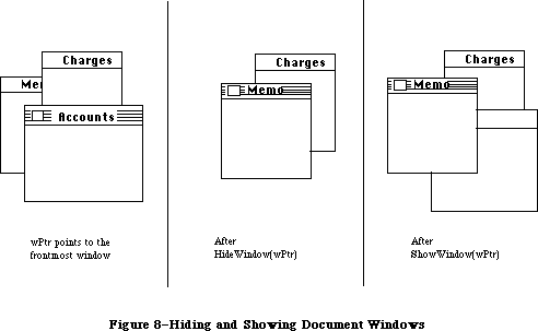 Figure 8–Hiding and Showing Document Windows
PROCEDURE ShowWindow (theWindow: WindowPtr);
ShowWindow makes theWindow visible. It does not change the front-to-back ordering of the windows. Remember that if you previously hid the frontmost window with HideWindow, HideWindow will have brought the window behind it to the front; so if you then do a ShowWindow of the window you hid, it will no longer be frontmost (see Figure 8). If theWindow is already visible, ShowWindow has no effect.
Note: Although it’s inadvisable, you can create a situation where the
frontmost window is invisible. If you do a ShowWindow of such a
window, it will highlight the window if it’s not already highlighted
and will generate an activate event to force this window from inactive
to active.
PROCEDURE ShowHide (theWindow: WindowPtr; showFlag: BOOLEAN);
If showFlag is TRUE, ShowHide makes theWindow visible if it’s not already visible and has no effect if it is already visible. If showFlag is FALSE, ShowHide makes theWindow invisible if it’s not already invisible and has no effect if it is already invisible. Unlike HideWindow and ShowWindow, ShowHide never changes the highlighting or front-to-back ordering of windows or generates activate events.
Warning: Use this procedure carefully, and only in special circumstances
where you need more control than allowed by HideWindow and
ShowWindow.
PROCEDURE HiliteWindow (theWindow: WindowPtr; fHilite: BOOLEAN);
If fHilite is TRUE, this procedure highlights theWindow if it’s not already highlighted and has no effect if it is highlighted. If fHilite is FALSE, HiliteWindow unhighlights theWindow if it is highlighted and has no effect if it’s not highlighted. The exact way a window is highlighted depends on its window definition function.
Normally you won’t have to call this procedure, since you should call SelectWindow to make a window active, and SelectWindow takes care of the necessary highlighting changes. Highlighting a window that isn’t the active window is contrary to the Macintosh User Interface Guidelines.
PROCEDURE BringToFront (theWindow: WindowPtr);
BringToFront brings theWindow to the front of all other windows and redraws the window as necessary. Normally you won’t have to call this procedure, since you should call SelectWindow to make a window active, and SelectWindow takes care of bringing the window to the front. If you do call BringToFront, however, remember to call HiliteWindow to make the necessary highlighting changes.
PROCEDURE SendBehind (theWindow,behindWindow: WindowPtr);
SendBehind sends theWindow behind behindWindow, redrawing any exposed windows. If behindWindow is NIL, it sends theWindow behind all other windows. If theWindow is the active window, it unhighlights theWindow, highlights the new active window, and generates the appropriate activate events.
Warning: Do not use SendBehind to deactivate a previously active window.
Calling SelectWindow to make a window active takes care of
deactivating the previously active window.
Note: If you’re moving theWindow closer to the front (that is, if it’s
initially even farther behind behindWindow), you must make the
following calls after calling SendBehind:
wPeek := POINTER(theWindow);
PaintOne(wPeek, wPeek^.strucRgn);
CalcVis(wPeek)
PaintOne and CalcVis are described under “Low-Level Routines”.
FUNCTION FrontWindow : WindowPtr;
FrontWindow returns a pointer to the first visible window in the window list
(that is, the active window). If there are no visible windows, it returns NIL.
Assembly-language note: In the global variable GhostWindow, you can store
a pointer to a window that’s not to be considered
frontmost even if it is (for example, if you want
to have a special editing window always present
and floating above all the others). If the window
pointed to by GhostWindow is the first window in
the window list, FrontWindow will return a pointer
to the next visible window.
PROCEDURE DrawGrowIcon (theWindow: WindowPtr);
Call DrawGrowIcon in response to an update or activate event involving a window that contains a size box in its content region. If theWindow is active, DrawGrowIcon draws the size box; otherwise, it draws whatever is appropriate to show that the window temporarily cannot be sized. The exact appearance and location of what’s drawn depend on the window definition function. For an active document window, DrawGrowIcon draws the size box icon in the bottom right corner of the portRect of the window’s grafPort, along with the lines delimiting the size box and scroll bar areas (15 pixels in from the right edge and bottom of the portRect). It doesn’t erase the scroll bar areas, so if the window doesn’t contain scroll bars you should erase those areas yourself after the window’s size changes. For an inactive document window, DrawGrowIcon draws only the lines delimiting the size box and scroll bar areas, and erases the size box icon.
_______________________________________________________________________________
»Mouse Location
PROCEDURE FindWindow (thePoint: Point; VAR whichWindow:windowPtr):INTEGER;
[Macintosh Plus, Macintosh SE, Macintosh II]
When a mouse-down event occurs, the application should call FindWindow with thePt equal to the point where the mouse button was pressed (in global coordinates, as stored in the where field of the event record). FindWindow tells which part of which window, if any, the mouse button was pressed in. If it was pressed in a window, the whichWindow parameter is set to the window pointer; otherwise, it’s set to NIL. The integer returned by FindWindow is one of the following predefined constants:
CONST inDesk = 0; {none of the following}
inMenuBar = 1; {in menu bar}
inSysWindow = 2; {in system window}
inContent = 3; {in content region (except grow, if active)}
inDrag = 4; {in drag region}
inGrow = 5; {in grow region (active window only)}
inGoAway = 6; {in go-away region (active window only)}
InDesk usually means that the mouse button was pressed on the desktop, outside the menu bar or any windows; however, it may also mean that the mouse button was pressed inside a window frame but not in the drag region or go-away region of the window. Usually one of the last four values is returned for windows created by the application.
The FindWindow procedure now calls the new menu bar definition procedure to determine whether the point where the mouse button was pressed lies in the menu bar.
Assembly-language note: If you store a pointer to a procedure in the
global variable DeskHook, it will be called when
the mouse button is pressed on the desktop. The
DeskHook procedure will be called with –1 in
register D0 to distinguish this use of it from its
use in drawing the desktop (discussed in the
description of InitWindows). Register A0 will
contain a pointer to the event record for the
mouse-down event. When you use DeskHook in this
way FindWindow does not return inDesk when the
mouse button is pressed on the desktop; it
returns inSysWindow, and the Desk Manager procedure
SystemClick calls the DeskHook procedure.
If the window is a documentProc type of window that doesn’t contain a size box, the application should treat inGrow the same as inContent; if it’s a noGrowDocProc type of window, FindWindow will never return inGrow for that window. If the window is a documentProc, noGrowDocProc, or rDocProc type of window with no close box, FindWindow will never return inGoAway for that window.
FUNCTION TrackGoAway (theWindow: WindowPtr; thePt: Point) : BOOLEAN;
When there’s a mouse-down event in the go-away region of theWindow, the application should call TrackGoAway with thePt equal to the point where the mouse button was pressed (in global coordinates, as stored in the where field of the event record). TrackGoAway keeps control until the mouse button is released, highlighting the go-away region as long as the mouse location remains inside it, and unhighlighting it when the mouse moves outside it. The exact way a window’s go-away region is highlighted depends on its window definition function; the highlighting of a document window’s close box is illustrated in Figure 9. When the mouse button is released, TrackGoAway unhighlights the go-away region and returns TRUE if the mouse is inside the go-away region or FALSE if it’s outside the region (in which case the application should do nothing).
Figure 8–Hiding and Showing Document Windows
PROCEDURE ShowWindow (theWindow: WindowPtr);
ShowWindow makes theWindow visible. It does not change the front-to-back ordering of the windows. Remember that if you previously hid the frontmost window with HideWindow, HideWindow will have brought the window behind it to the front; so if you then do a ShowWindow of the window you hid, it will no longer be frontmost (see Figure 8). If theWindow is already visible, ShowWindow has no effect.
Note: Although it’s inadvisable, you can create a situation where the
frontmost window is invisible. If you do a ShowWindow of such a
window, it will highlight the window if it’s not already highlighted
and will generate an activate event to force this window from inactive
to active.
PROCEDURE ShowHide (theWindow: WindowPtr; showFlag: BOOLEAN);
If showFlag is TRUE, ShowHide makes theWindow visible if it’s not already visible and has no effect if it is already visible. If showFlag is FALSE, ShowHide makes theWindow invisible if it’s not already invisible and has no effect if it is already invisible. Unlike HideWindow and ShowWindow, ShowHide never changes the highlighting or front-to-back ordering of windows or generates activate events.
Warning: Use this procedure carefully, and only in special circumstances
where you need more control than allowed by HideWindow and
ShowWindow.
PROCEDURE HiliteWindow (theWindow: WindowPtr; fHilite: BOOLEAN);
If fHilite is TRUE, this procedure highlights theWindow if it’s not already highlighted and has no effect if it is highlighted. If fHilite is FALSE, HiliteWindow unhighlights theWindow if it is highlighted and has no effect if it’s not highlighted. The exact way a window is highlighted depends on its window definition function.
Normally you won’t have to call this procedure, since you should call SelectWindow to make a window active, and SelectWindow takes care of the necessary highlighting changes. Highlighting a window that isn’t the active window is contrary to the Macintosh User Interface Guidelines.
PROCEDURE BringToFront (theWindow: WindowPtr);
BringToFront brings theWindow to the front of all other windows and redraws the window as necessary. Normally you won’t have to call this procedure, since you should call SelectWindow to make a window active, and SelectWindow takes care of bringing the window to the front. If you do call BringToFront, however, remember to call HiliteWindow to make the necessary highlighting changes.
PROCEDURE SendBehind (theWindow,behindWindow: WindowPtr);
SendBehind sends theWindow behind behindWindow, redrawing any exposed windows. If behindWindow is NIL, it sends theWindow behind all other windows. If theWindow is the active window, it unhighlights theWindow, highlights the new active window, and generates the appropriate activate events.
Warning: Do not use SendBehind to deactivate a previously active window.
Calling SelectWindow to make a window active takes care of
deactivating the previously active window.
Note: If you’re moving theWindow closer to the front (that is, if it’s
initially even farther behind behindWindow), you must make the
following calls after calling SendBehind:
wPeek := POINTER(theWindow);
PaintOne(wPeek, wPeek^.strucRgn);
CalcVis(wPeek)
PaintOne and CalcVis are described under “Low-Level Routines”.
FUNCTION FrontWindow : WindowPtr;
FrontWindow returns a pointer to the first visible window in the window list
(that is, the active window). If there are no visible windows, it returns NIL.
Assembly-language note: In the global variable GhostWindow, you can store
a pointer to a window that’s not to be considered
frontmost even if it is (for example, if you want
to have a special editing window always present
and floating above all the others). If the window
pointed to by GhostWindow is the first window in
the window list, FrontWindow will return a pointer
to the next visible window.
PROCEDURE DrawGrowIcon (theWindow: WindowPtr);
Call DrawGrowIcon in response to an update or activate event involving a window that contains a size box in its content region. If theWindow is active, DrawGrowIcon draws the size box; otherwise, it draws whatever is appropriate to show that the window temporarily cannot be sized. The exact appearance and location of what’s drawn depend on the window definition function. For an active document window, DrawGrowIcon draws the size box icon in the bottom right corner of the portRect of the window’s grafPort, along with the lines delimiting the size box and scroll bar areas (15 pixels in from the right edge and bottom of the portRect). It doesn’t erase the scroll bar areas, so if the window doesn’t contain scroll bars you should erase those areas yourself after the window’s size changes. For an inactive document window, DrawGrowIcon draws only the lines delimiting the size box and scroll bar areas, and erases the size box icon.
_______________________________________________________________________________
»Mouse Location
PROCEDURE FindWindow (thePoint: Point; VAR whichWindow:windowPtr):INTEGER;
[Macintosh Plus, Macintosh SE, Macintosh II]
When a mouse-down event occurs, the application should call FindWindow with thePt equal to the point where the mouse button was pressed (in global coordinates, as stored in the where field of the event record). FindWindow tells which part of which window, if any, the mouse button was pressed in. If it was pressed in a window, the whichWindow parameter is set to the window pointer; otherwise, it’s set to NIL. The integer returned by FindWindow is one of the following predefined constants:
CONST inDesk = 0; {none of the following}
inMenuBar = 1; {in menu bar}
inSysWindow = 2; {in system window}
inContent = 3; {in content region (except grow, if active)}
inDrag = 4; {in drag region}
inGrow = 5; {in grow region (active window only)}
inGoAway = 6; {in go-away region (active window only)}
InDesk usually means that the mouse button was pressed on the desktop, outside the menu bar or any windows; however, it may also mean that the mouse button was pressed inside a window frame but not in the drag region or go-away region of the window. Usually one of the last four values is returned for windows created by the application.
The FindWindow procedure now calls the new menu bar definition procedure to determine whether the point where the mouse button was pressed lies in the menu bar.
Assembly-language note: If you store a pointer to a procedure in the
global variable DeskHook, it will be called when
the mouse button is pressed on the desktop. The
DeskHook procedure will be called with –1 in
register D0 to distinguish this use of it from its
use in drawing the desktop (discussed in the
description of InitWindows). Register A0 will
contain a pointer to the event record for the
mouse-down event. When you use DeskHook in this
way FindWindow does not return inDesk when the
mouse button is pressed on the desktop; it
returns inSysWindow, and the Desk Manager procedure
SystemClick calls the DeskHook procedure.
If the window is a documentProc type of window that doesn’t contain a size box, the application should treat inGrow the same as inContent; if it’s a noGrowDocProc type of window, FindWindow will never return inGrow for that window. If the window is a documentProc, noGrowDocProc, or rDocProc type of window with no close box, FindWindow will never return inGoAway for that window.
FUNCTION TrackGoAway (theWindow: WindowPtr; thePt: Point) : BOOLEAN;
When there’s a mouse-down event in the go-away region of theWindow, the application should call TrackGoAway with thePt equal to the point where the mouse button was pressed (in global coordinates, as stored in the where field of the event record). TrackGoAway keeps control until the mouse button is released, highlighting the go-away region as long as the mouse location remains inside it, and unhighlighting it when the mouse moves outside it. The exact way a window’s go-away region is highlighted depends on its window definition function; the highlighting of a document window’s close box is illustrated in Figure 9. When the mouse button is released, TrackGoAway unhighlights the go-away region and returns TRUE if the mouse is inside the go-away region or FALSE if it’s outside the region (in which case the application should do nothing).
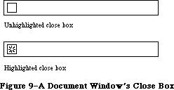 Figure 9–A Document Window’s Close Box
Assembly-language note: If you store a pointer to a procedure in the
global variable DragHook, TrackGoAway will call
that procedure repeatedly (with no parameters) for
as long as the user holds down the mouse button.
_______________________________________________________________________________
»Window Movement and Sizing
PROCEDURE MoveWindow (theWindow:windowPtr; hGlobal, vGlobal:INTEGER;
front: BOOLEAN); [Macintosh II]
MoveWindow moves theWindow to another part of the screen, without affecting its size or plane. The top left corner of the portRect of the window’s grafPort is moved to the screen point indicated by the global coordinates hGlobal and vGlobal. The local coordinates of the top left corner remain the same. If the front parameter is TRUE and theWindow isn’t the active window, MoveWindow makes it the active window by calling SelectWindow(theWindow).
The MoveWindow routine formerly copied a window’s entire structure region. On multiple-screen systems, MoveWindow now copies only the portion of the window that will remain on the same screen. All other parts of the window are not copied, and are redrawn on the next update event. When a window’s content crosses screen boundaries, MoveWindow may post additional updates on multiple screen systems.
For new applications, the specified dragging bounds should be the bounding box of the GrayRgn. To support existing programs, if the dragging bounds passed to MoveWindow are within six pixels of the current screenbits.bounds on the left, right, and bottom, and are within thirty-six pixels of the
screenbits.bounds.top, the GrayRgn’s bounding box is substituted.
PROCEDURE DragWindow (theWindow: WindowPtr; startPt: Point; boundsRect: Rect);
When there’s a mouse-down event in the drag region of theWindow, the application should call DragWindow with startPt equal to the point where the mouse button was pressed (in global coordinates, as stored in the where field of the event record). DragWindow pulls a dotted outline of theWindow around, following the movements of the mouse until the button is released. When the mouse button is released, DragWindow calls MoveWindow to move theWindow to the location to which it was dragged. If theWindow isn’t the active window (and the Command key wasn’t being held down), DragWindow makes it the active window by passing TRUE for the front parameter when calling MoveWindow. If the Command key was being held down, the window is moved without being made the active window.
BoundsRect is also given in global coordinates. If the mouse button is released when the mouse location is outside the limits of boundsRect, DragWindow returns without moving theWindow or making it the active window. For a document window, boundsRect typically will be four pixels in from the menu bar and from the other edges of the screen, to ensure that there won’t be less than a four-pixel-square area of the title bar visible on the screen.
Assembly-language note: As for TrackGoAway, if you store a pointer to a
procedure in the global variable DragHook, that
procedure will be called repeatedly while the user
holds down the mouse button. (DragWindow calls
DragGrayRgn, which calls the DragHook procedure).
FUNCTION GrowWindow (theWindow:windowPtr: startPt:Point;
sizeRect: Rect):LONGINT; [Macintosh II]
When there’s a mouse-down event in the grow region of theWindow, the application should call GrowWindow with startPt equal to the point where the mouse button was pressed (in global coordinates, as stored in the where field of the event record). GrowWindow pulls a grow image of the window around, following the movements of the mouse until the button is released. The grow image for a document window is a dotted outline of the entire window and also the lines delimiting the title bar, size box, and scroll bar areas; Figure 10 illustrates this for a document window containing both scroll bars, but the grow image would be the same even if the window contained one or no scroll bars. In general, the grow image is defined in the window definition function and is whatever is appropriate to show that the window’s size will change.
On multiple-screen systems, the GrowWindow routine is modified so that windows can be stretched only a small amount onto other screens. This restriction can be removed by holding down the command key while growing the window, allowing windows to cover the full extent of the multiscreen desktop.
Figure 9–A Document Window’s Close Box
Assembly-language note: If you store a pointer to a procedure in the
global variable DragHook, TrackGoAway will call
that procedure repeatedly (with no parameters) for
as long as the user holds down the mouse button.
_______________________________________________________________________________
»Window Movement and Sizing
PROCEDURE MoveWindow (theWindow:windowPtr; hGlobal, vGlobal:INTEGER;
front: BOOLEAN); [Macintosh II]
MoveWindow moves theWindow to another part of the screen, without affecting its size or plane. The top left corner of the portRect of the window’s grafPort is moved to the screen point indicated by the global coordinates hGlobal and vGlobal. The local coordinates of the top left corner remain the same. If the front parameter is TRUE and theWindow isn’t the active window, MoveWindow makes it the active window by calling SelectWindow(theWindow).
The MoveWindow routine formerly copied a window’s entire structure region. On multiple-screen systems, MoveWindow now copies only the portion of the window that will remain on the same screen. All other parts of the window are not copied, and are redrawn on the next update event. When a window’s content crosses screen boundaries, MoveWindow may post additional updates on multiple screen systems.
For new applications, the specified dragging bounds should be the bounding box of the GrayRgn. To support existing programs, if the dragging bounds passed to MoveWindow are within six pixels of the current screenbits.bounds on the left, right, and bottom, and are within thirty-six pixels of the
screenbits.bounds.top, the GrayRgn’s bounding box is substituted.
PROCEDURE DragWindow (theWindow: WindowPtr; startPt: Point; boundsRect: Rect);
When there’s a mouse-down event in the drag region of theWindow, the application should call DragWindow with startPt equal to the point where the mouse button was pressed (in global coordinates, as stored in the where field of the event record). DragWindow pulls a dotted outline of theWindow around, following the movements of the mouse until the button is released. When the mouse button is released, DragWindow calls MoveWindow to move theWindow to the location to which it was dragged. If theWindow isn’t the active window (and the Command key wasn’t being held down), DragWindow makes it the active window by passing TRUE for the front parameter when calling MoveWindow. If the Command key was being held down, the window is moved without being made the active window.
BoundsRect is also given in global coordinates. If the mouse button is released when the mouse location is outside the limits of boundsRect, DragWindow returns without moving theWindow or making it the active window. For a document window, boundsRect typically will be four pixels in from the menu bar and from the other edges of the screen, to ensure that there won’t be less than a four-pixel-square area of the title bar visible on the screen.
Assembly-language note: As for TrackGoAway, if you store a pointer to a
procedure in the global variable DragHook, that
procedure will be called repeatedly while the user
holds down the mouse button. (DragWindow calls
DragGrayRgn, which calls the DragHook procedure).
FUNCTION GrowWindow (theWindow:windowPtr: startPt:Point;
sizeRect: Rect):LONGINT; [Macintosh II]
When there’s a mouse-down event in the grow region of theWindow, the application should call GrowWindow with startPt equal to the point where the mouse button was pressed (in global coordinates, as stored in the where field of the event record). GrowWindow pulls a grow image of the window around, following the movements of the mouse until the button is released. The grow image for a document window is a dotted outline of the entire window and also the lines delimiting the title bar, size box, and scroll bar areas; Figure 10 illustrates this for a document window containing both scroll bars, but the grow image would be the same even if the window contained one or no scroll bars. In general, the grow image is defined in the window definition function and is whatever is appropriate to show that the window’s size will change.
On multiple-screen systems, the GrowWindow routine is modified so that windows can be stretched only a small amount onto other screens. This restriction can be removed by holding down the command key while growing the window, allowing windows to cover the full extent of the multiscreen desktop.
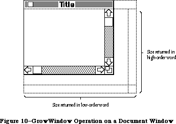 Figure 10–GrowWindow Operation on a Document Window
The application should subsequently call SizeWindow to change the portRect of the window’s grafPort to the new one outlined by the grow image. The sizeRect parameter specifies limits, in pixels, on the vertical and horizontal measurements of what will be the new portRect. SizeRect.top is the minimum vertical measurement, sizeRect.left is the minimum horizontal measurement, sizeRect.bottom is the maximum vertical measurement, and sizeRect.right is the maximum horizontal measurement.
GrowWindow returns the actual size for the new portRect as outlined by the grow image when the mouse button is released. The high-order word of the long integer is the vertical measurement in pixels and the low-order word is the horizontal measurement. A return value of 0 indicates that the size is the same as that of the current portRect.
Note: The Toolbox Utility function HiWord takes a long integer as a
parameter and returns an integer equal to its high-order word; the
function LoWord returns the low-order word.
Assembly-language note: Like TrackGoAway, GrowWindow repeatedly calls the
procedure pointed to by the global variable DragHook
(if any) as long as the mouse button is held down.
PROCEDURE SizeWindow (theWindow: WindowPtr; w,h: INTEGER; fUpdate: BOOLEAN);
SizeWindow enlarges or shrinks the portRect of theWindow’s grafPort to the width and height specified by w and h, or does nothing if w and h are 0. The window’s position on the screen does not change. The new window frame is drawn; if the width of a document window changes, the title is again centered in the title bar, or is truncated if it no longer fits. If fUpdate is TRUE, SizeWindow accumulates any newly created area of the content region into the update region (see Figure 11); normally this is what you’ll want. If you pass FALSE for fUpdate, you’re responsible for the update region maintenance yourself. For more information, see InvalRect and ValidRect.
Figure 10–GrowWindow Operation on a Document Window
The application should subsequently call SizeWindow to change the portRect of the window’s grafPort to the new one outlined by the grow image. The sizeRect parameter specifies limits, in pixels, on the vertical and horizontal measurements of what will be the new portRect. SizeRect.top is the minimum vertical measurement, sizeRect.left is the minimum horizontal measurement, sizeRect.bottom is the maximum vertical measurement, and sizeRect.right is the maximum horizontal measurement.
GrowWindow returns the actual size for the new portRect as outlined by the grow image when the mouse button is released. The high-order word of the long integer is the vertical measurement in pixels and the low-order word is the horizontal measurement. A return value of 0 indicates that the size is the same as that of the current portRect.
Note: The Toolbox Utility function HiWord takes a long integer as a
parameter and returns an integer equal to its high-order word; the
function LoWord returns the low-order word.
Assembly-language note: Like TrackGoAway, GrowWindow repeatedly calls the
procedure pointed to by the global variable DragHook
(if any) as long as the mouse button is held down.
PROCEDURE SizeWindow (theWindow: WindowPtr; w,h: INTEGER; fUpdate: BOOLEAN);
SizeWindow enlarges or shrinks the portRect of theWindow’s grafPort to the width and height specified by w and h, or does nothing if w and h are 0. The window’s position on the screen does not change. The new window frame is drawn; if the width of a document window changes, the title is again centered in the title bar, or is truncated if it no longer fits. If fUpdate is TRUE, SizeWindow accumulates any newly created area of the content region into the update region (see Figure 11); normally this is what you’ll want. If you pass FALSE for fUpdate, you’re responsible for the update region maintenance yourself. For more information, see InvalRect and ValidRect.
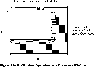 Figure 11–SizeWindow Operation on a Document Window
FUNCTION TrackBox (theWindow: WindowPtr; thePt: Point;
partCode: INTEGER) : BOOLEAN;
When there’s a mouse-down event in the zoom-window box of theWindow, the application should call TrackBox with thePt equal to the point where the mouse button was pressed (in global coordinates, as stored in the where field of the event record). The partCode parameter contains the constant (either inZoomIn or inZoomOut) returned by FindWindow. TrackBox keeps control until the mouse button is released; it highlights the zoom-window box in the same way as a window’s close box is highlighted. When the mouse button is released, TrackBox unhighlights the zoom-window box and returns TRUE if the mouse is inside the zoom-window box or FALSE if it’s outside the box (in which case the application should do nothing).
PROCEDURE ZoomWindow(theWindow:windowPtr; partCode: INTEGER;
front: BOOLEAN); [Macintosh II]
Call ZoomWindow after a call to TrackBox that returns TRUE. The partCode parameter contains the constant (either inZoomIn or inZoomOut) returned by FindWindow. The window will be zoomed either out or in, depending on the state of the window specified by partCode. If the window is already in the state specified by partCode, ZoomWindow does nothing. If the front parameter is TRUE, the window will be brought to the front; otherwise, the window is left where it is. (This means a window can be zoomed without necessarily becoming the active window.)
On multiple-screen systems, applications that call ZoomWindow with a new size based on the screen rectangle (screenBits.bounds) will now cause any windows not on the main screen to zoom to full size on the main screen. To perform properly in a multiscreen environment, these applications should test which screen contains the greatest area of the window to be zoomed, and then zoom to the screen rectangle (GDRect) for that screen device. See the Graphics Devices chapter for information on obtaining the GDRect value for a device.
For best results, call the QuickDraw procedure EraseRect with the portRect field of theWindow’s grafPort before calling ZoomWindow.
Warning: Using the QuickDraw procedure SetPort, set thePort to the window’s
port before calling ZoomWindow.
Note: ZoomWindow is in no way tied to the TrackBox function and could just
as easily be called in response to a selection from a menu.
_______________________________________________________________________________
»Update Region Maintenance
PROCEDURE InvalRect (badRect: Rect);
InvalRect accumulates the given rectangle into the update region of the window whose grafPort is the current port. This tells the Window Manager that the rectangle has changed and must be updated. The rectangle is given in local coordinates and is clipped to the window’s content region.
For example, this procedure is useful when you’re calling SizeWindow for a document window that contains a size box or scroll bars. Suppose you’re going to call SizeWindow with fUpdate=TRUE. If the window is enlarged as shown in Figure 10, you’ll want not only the newly created part of the content region to be updated, but also the two rectangular areas containing the (former) size box and scroll bars; before calling SizeWindow, you can call InvalRect twice to accumulate those areas into the update region. In case the window is made smaller, you’ll want the new size box and scroll bar areas to be updated, and so can similarly call InvalRect for those areas after calling SizeWindow. See Figure 12 for an illustration of this type of update region maintenance.
As another example, suppose your application scrolls up text in a document window and wants to show new text added at the bottom of the window. You can cause the added text to be redrawn by accumulating that area into the update region with InvalRect.
PROCEDURE InvalRgn (badRgn: RgnHandle);
InvalRgn is the same as InvalRect but for a region that has changed rather than a rectangle.
Figure 11–SizeWindow Operation on a Document Window
FUNCTION TrackBox (theWindow: WindowPtr; thePt: Point;
partCode: INTEGER) : BOOLEAN;
When there’s a mouse-down event in the zoom-window box of theWindow, the application should call TrackBox with thePt equal to the point where the mouse button was pressed (in global coordinates, as stored in the where field of the event record). The partCode parameter contains the constant (either inZoomIn or inZoomOut) returned by FindWindow. TrackBox keeps control until the mouse button is released; it highlights the zoom-window box in the same way as a window’s close box is highlighted. When the mouse button is released, TrackBox unhighlights the zoom-window box and returns TRUE if the mouse is inside the zoom-window box or FALSE if it’s outside the box (in which case the application should do nothing).
PROCEDURE ZoomWindow(theWindow:windowPtr; partCode: INTEGER;
front: BOOLEAN); [Macintosh II]
Call ZoomWindow after a call to TrackBox that returns TRUE. The partCode parameter contains the constant (either inZoomIn or inZoomOut) returned by FindWindow. The window will be zoomed either out or in, depending on the state of the window specified by partCode. If the window is already in the state specified by partCode, ZoomWindow does nothing. If the front parameter is TRUE, the window will be brought to the front; otherwise, the window is left where it is. (This means a window can be zoomed without necessarily becoming the active window.)
On multiple-screen systems, applications that call ZoomWindow with a new size based on the screen rectangle (screenBits.bounds) will now cause any windows not on the main screen to zoom to full size on the main screen. To perform properly in a multiscreen environment, these applications should test which screen contains the greatest area of the window to be zoomed, and then zoom to the screen rectangle (GDRect) for that screen device. See the Graphics Devices chapter for information on obtaining the GDRect value for a device.
For best results, call the QuickDraw procedure EraseRect with the portRect field of theWindow’s grafPort before calling ZoomWindow.
Warning: Using the QuickDraw procedure SetPort, set thePort to the window’s
port before calling ZoomWindow.
Note: ZoomWindow is in no way tied to the TrackBox function and could just
as easily be called in response to a selection from a menu.
_______________________________________________________________________________
»Update Region Maintenance
PROCEDURE InvalRect (badRect: Rect);
InvalRect accumulates the given rectangle into the update region of the window whose grafPort is the current port. This tells the Window Manager that the rectangle has changed and must be updated. The rectangle is given in local coordinates and is clipped to the window’s content region.
For example, this procedure is useful when you’re calling SizeWindow for a document window that contains a size box or scroll bars. Suppose you’re going to call SizeWindow with fUpdate=TRUE. If the window is enlarged as shown in Figure 10, you’ll want not only the newly created part of the content region to be updated, but also the two rectangular areas containing the (former) size box and scroll bars; before calling SizeWindow, you can call InvalRect twice to accumulate those areas into the update region. In case the window is made smaller, you’ll want the new size box and scroll bar areas to be updated, and so can similarly call InvalRect for those areas after calling SizeWindow. See Figure 12 for an illustration of this type of update region maintenance.
As another example, suppose your application scrolls up text in a document window and wants to show new text added at the bottom of the window. You can cause the added text to be redrawn by accumulating that area into the update region with InvalRect.
PROCEDURE InvalRgn (badRgn: RgnHandle);
InvalRgn is the same as InvalRect but for a region that has changed rather than a rectangle.
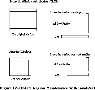 Figure 12–Update Region Maintenance with InvalRect
PROCEDURE ValidRect (goodRect: Rect);
ValidRect removes goodRect from the update region of the window whose grafPort is the current port. This tells the Window Manager that the application has already drawn the rectangle and to cancel any updates accumulated for that area. The rectangle is clipped to the window’s content region and is given in local coordinates. Using ValidRect results in better performance and less redundant redrawing in the window.
For example, suppose you’ve called SizeWindow with fUpdate=TRUE for a document window that contains a size box or scroll bars. Depending on the dimensions of the newly sized window, the new size box and scroll bar areas may or may not have been accumulated into the window’s update region. After calling SizeWindow, you can redraw the size box or scroll bars immediately and then call ValidRect for the areas they occupy in case they were in fact accumulated into the update region; this will avoid redundant drawing.
PROCEDURE ValidRgn (goodRgn: RgnHandle);
ValidRgn is the same as ValidRect but for a region that has been drawn rather than a rectangle.
PROCEDURE BeginUpdate (theWindow: WindowPtr);
Call BeginUpdate when an update event occurs for theWindow. BeginUpdate replaces the visRgn of the window’s grafPort with the intersection of the visRgn and the update region and then sets the window’s update region to an empty region. You would then usually draw the entire content region, though it suffices to draw only the visRgn; in either case, only the parts of the window that require updating will actually be drawn on the screen. Every call to BeginUpdate must be balanced by a call to EndUpdate. (See “How a Window is Drawn”.)
Note: In Pascal, BeginUpdate and EndUpdate calls can’t be nested (that is,
you must call EndUpdate before the next call to BeginUpdate).
Assembly-language note: A handle to a copy of the original visRgn (in
global coordinates) is stored in the global
variable SaveVisRgn. You can nest BeginUpdate and
EndUpdate calls in assembly language if you save
and restore this region.
PROCEDURE EndUpdate (theWindow: WindowPtr);
Call EndUpdate to restore the normal visRgn of theWindow’s grafPort, which was changed by BeginUpdate as described above.
_______________________________________________________________________________
»Color Window Routines
FUNCTION NewCWindow (wStorage: Ptr; boundsRect: Rect; title: Str255;
visible: BOOLEAN; procID: INTEGER; behind: WindowPtr;
goAwayFlag: BOOLEAN; refCon: LONGINT) : WindowPtr;
[Macintosh II]
The NewCWindow routine creates a new color window. This routine is similar to the old routine NewWindow, but creates a window based on a cGrafPort instead of an old-style grafPort.
FUNCTION GetNewCWindow (windowID: INTEGER; wStorage: Ptr;
behind: CWindowPtr) : WindowPtr; [Macintosh II]
The GetNewCWindow routine creates a new color window from a template in a resource file. It’s analogous to the old routine GetNewWindow, but it creates a window based on a cGrafPort instead of an old-style grafPort. GetNewCWindow checks the 'wctb' resource, and if it contains the same resource ID, it colors the window. The backColor of the window is set to the new content color. This allows an application to begin its update with an EraseRect without changing the background color.
PROCEDURE SetWinColor (theWindow: WindowPtr; newColorTable: WCTabHandle);
[Macintosh II]
The SetWinColor routine sets a window’s color table. If the window currently has no auxiliary window record, a new one is created with the given color table and added to the head of the auxiliary window list. If there is already an auxiliary record for the window, its color table is replaced by the contents of newColorTable. The window is then automatically redrawn in the new colors. If SetWinColor is performed on a cWindow, it sets the backColor of the window to the new content color. This allows an application to begin its update without changing the background color.
If newColorTable has the same contents as the default color table, the window’s existing auxiliary record and color table are removed from the auxiliary window list and deallocated. If theWindow = NIL, the operation modifies the default color table in memory. The system never disposes of color tables that are resources when the resource bit is set; 'wctb' resources can’t be purgeable.
FUNCTION GetAuxWin (theWindow: WindowPtr;
VAR awHndl: AuxWinHandle) : BOOLEAN; [Macintosh II]
The GetAuxWin routine returns a handle to a window’s auxiliary window record:
• If the given window has an auxiliary record, its handle is returned in
awHndl and the function returns TRUE.
• If the window has no auxiliary record, a handle to the default record
is returned in awHndl and the function returns FALSE.
• If theWindow = NIL, a handle to the default record is returned in awHndl
and the function returns TRUE.
FUNCTION GetWVariant (whichWindow:WindowPtr): INTEGER;
[Macintosh Plus, Macintosh SE, Macintosh II]
GetWVariant returns the variant code for the window described by whichWindow. See the section “Defining Your Own Windows” for more information about variants.
FUNCTION GetGrayRgn : regionHandle;
[Macintosh Plus, Macintosh SE, Macintosh II]
The GetGrayRgn function returns a handle to the current desktop region stored in the global variable GrayRgn.
_______________________________________________________________________________
»Miscellaneous Routines
PROCEDURE SetWRefCon (theWindow: WindowPtr; data: LONGINT);
SetWRefCon sets theWindow’s reference value to the given data.
FUNCTION GetWRefCon (theWindow: WindowPtr) : LONGINT;
GetWRefCon returns theWindow’s current reference value.
PROCEDURE SetWindowPic (theWindow: WindowPtr; pic: PicHandle);
SetWindowPic stores the given picture handle in the window record for theWindow, so that when theWindow’s contents are to be drawn, the Window Manager will draw this picture rather than generate an update event.
FUNCTION GetWindowPic (theWindow: WindowPtr) : PicHandle;
GetWindowPic returns the handle to the picture that draws theWindow’s contents, previously stored with SetWindowPic.
FUNCTION PinRect (theRect: Rect; thePt: Point) : LONGINT;
PinRect “pins” thePt inside theRect: If thePt is inside theRect, thePt is returned; otherwise, the point associated with the nearest pixel within theRect is returned. (The high-order word of the long integer returned is the vertical coordinate; the low-order word is the horizontal coordinate.) More precisely, for theRect (left,top) (right,bottom) and thePt (h,v), PinRect does the following:
• If h < left, it returns left.
• If v < top, it returns top.
• If h > right, it returns right–1.
• If v > bottom, it returns bottom–1.
Note: The 1 is subtracted when thePt is below or to the right of theRect
so that a pixel drawn at that point will lie within theRect. However,
if thePt is exactly on the bottom or right edge of theRect, 1 should
be subtracted but isn’t.
FUNCTION DragGrayRgn (theRgn: RgnHandle; startPt: Point;
lmitRect, slopRect: Rect; axis: INTEGER;
actionProc:ProcPtr):LONGINT; [Macintosh II]
Called when the mouse button is down inside theRgn, DragGrayRgn pulls a dotted
(gray) outline of the region around, following the movements of the mouse until the button is released. DragWindow calls this function before actually moving the window. You can call it yourself to pull around the outline of any region, and then use the information it returns to determine where to move the region.
On multiple-screen systems, the Window Manager now checks the screen rectangle
(screenBits.bounds) when the DragGrayRgn routine is called. This allows the object being dragged to be positioned anywhere on the multiscreen desktop. If the dragging bounds are based on screenBits.bound, the dragging boundsRect will be changed to the bounding box of the grayRgn. The Window Manager’s criteria for modifying the bounds are (1) the left, bottom, and right are within six pixels of screenBits.bound, and (2) the top is within 36 pixels of screenBits.bounds.top. If the dragging bounds are modified, the lmitRect parameter is also similarly modified.
Note: DragGrayRgn alters the region; if you don’t want the original region
changed, pass DragGrayRgn a handle to a copy.
The startPt parameter is assumed to be the point where the mouse button was originally pressed, in the local coordinates of the current grafPort.
LmitRect and slopRect are also in the local coordinates of the current grafPort. To explain these parameters, the concept of “offset point” must be introduced: This is initially the point whose vertical and horizontal offsets from the top left corner of the region’s enclosing rectangle are the same as those of startPt. The offset point follows the mouse location, except that DragGrayRgn will never move the offset point outside limitRect; this limits the travel of the region’s outline (but not the movements of the mouse). SlopRect, which should completely enclose limitRect, allows the user some “slop” in moving the mouse. DragGrayRgn’s behavior while tracking the mouse depends on the location of the mouse with respect to these two rectangles:
• When the mouse is inside lmitRect, the region’s outline follows it
normally. If the mouse button is released there, the region should be
moved to the mouse location.
• When the mouse is outside lmitRect but inside slopRect, DragGrayRgn
“pins” the offset point to the edge of lmitRect. If the mouse button
is released there, the region should be moved to this pinned location.
• When the mouse is outside slopRect, the outline disappears from the
screen, but DragGrayRgn continues to follow the mouse; if it moves back
into slopRect, the outline reappears. If the mouse button is released
outside slopRect, the region should not be moved from its original
position.
Figure 13 illustrates what happens when the mouse is moved outside lmitRect but inside slopRect, for a rectangular region. The offset point is pinned as the mouse location moves on.
If the mouse button is released within slopRect, the high-order word of the value returned by DragGrayRgn contains the vertical coordinate of the ending mouse location minus that of startPt and the low-order word contains the difference between the horizontal coordinates. If the mouse button is released outside slopRect, both words contain –32768 ($8000).
Figure 12–Update Region Maintenance with InvalRect
PROCEDURE ValidRect (goodRect: Rect);
ValidRect removes goodRect from the update region of the window whose grafPort is the current port. This tells the Window Manager that the application has already drawn the rectangle and to cancel any updates accumulated for that area. The rectangle is clipped to the window’s content region and is given in local coordinates. Using ValidRect results in better performance and less redundant redrawing in the window.
For example, suppose you’ve called SizeWindow with fUpdate=TRUE for a document window that contains a size box or scroll bars. Depending on the dimensions of the newly sized window, the new size box and scroll bar areas may or may not have been accumulated into the window’s update region. After calling SizeWindow, you can redraw the size box or scroll bars immediately and then call ValidRect for the areas they occupy in case they were in fact accumulated into the update region; this will avoid redundant drawing.
PROCEDURE ValidRgn (goodRgn: RgnHandle);
ValidRgn is the same as ValidRect but for a region that has been drawn rather than a rectangle.
PROCEDURE BeginUpdate (theWindow: WindowPtr);
Call BeginUpdate when an update event occurs for theWindow. BeginUpdate replaces the visRgn of the window’s grafPort with the intersection of the visRgn and the update region and then sets the window’s update region to an empty region. You would then usually draw the entire content region, though it suffices to draw only the visRgn; in either case, only the parts of the window that require updating will actually be drawn on the screen. Every call to BeginUpdate must be balanced by a call to EndUpdate. (See “How a Window is Drawn”.)
Note: In Pascal, BeginUpdate and EndUpdate calls can’t be nested (that is,
you must call EndUpdate before the next call to BeginUpdate).
Assembly-language note: A handle to a copy of the original visRgn (in
global coordinates) is stored in the global
variable SaveVisRgn. You can nest BeginUpdate and
EndUpdate calls in assembly language if you save
and restore this region.
PROCEDURE EndUpdate (theWindow: WindowPtr);
Call EndUpdate to restore the normal visRgn of theWindow’s grafPort, which was changed by BeginUpdate as described above.
_______________________________________________________________________________
»Color Window Routines
FUNCTION NewCWindow (wStorage: Ptr; boundsRect: Rect; title: Str255;
visible: BOOLEAN; procID: INTEGER; behind: WindowPtr;
goAwayFlag: BOOLEAN; refCon: LONGINT) : WindowPtr;
[Macintosh II]
The NewCWindow routine creates a new color window. This routine is similar to the old routine NewWindow, but creates a window based on a cGrafPort instead of an old-style grafPort.
FUNCTION GetNewCWindow (windowID: INTEGER; wStorage: Ptr;
behind: CWindowPtr) : WindowPtr; [Macintosh II]
The GetNewCWindow routine creates a new color window from a template in a resource file. It’s analogous to the old routine GetNewWindow, but it creates a window based on a cGrafPort instead of an old-style grafPort. GetNewCWindow checks the 'wctb' resource, and if it contains the same resource ID, it colors the window. The backColor of the window is set to the new content color. This allows an application to begin its update with an EraseRect without changing the background color.
PROCEDURE SetWinColor (theWindow: WindowPtr; newColorTable: WCTabHandle);
[Macintosh II]
The SetWinColor routine sets a window’s color table. If the window currently has no auxiliary window record, a new one is created with the given color table and added to the head of the auxiliary window list. If there is already an auxiliary record for the window, its color table is replaced by the contents of newColorTable. The window is then automatically redrawn in the new colors. If SetWinColor is performed on a cWindow, it sets the backColor of the window to the new content color. This allows an application to begin its update without changing the background color.
If newColorTable has the same contents as the default color table, the window’s existing auxiliary record and color table are removed from the auxiliary window list and deallocated. If theWindow = NIL, the operation modifies the default color table in memory. The system never disposes of color tables that are resources when the resource bit is set; 'wctb' resources can’t be purgeable.
FUNCTION GetAuxWin (theWindow: WindowPtr;
VAR awHndl: AuxWinHandle) : BOOLEAN; [Macintosh II]
The GetAuxWin routine returns a handle to a window’s auxiliary window record:
• If the given window has an auxiliary record, its handle is returned in
awHndl and the function returns TRUE.
• If the window has no auxiliary record, a handle to the default record
is returned in awHndl and the function returns FALSE.
• If theWindow = NIL, a handle to the default record is returned in awHndl
and the function returns TRUE.
FUNCTION GetWVariant (whichWindow:WindowPtr): INTEGER;
[Macintosh Plus, Macintosh SE, Macintosh II]
GetWVariant returns the variant code for the window described by whichWindow. See the section “Defining Your Own Windows” for more information about variants.
FUNCTION GetGrayRgn : regionHandle;
[Macintosh Plus, Macintosh SE, Macintosh II]
The GetGrayRgn function returns a handle to the current desktop region stored in the global variable GrayRgn.
_______________________________________________________________________________
»Miscellaneous Routines
PROCEDURE SetWRefCon (theWindow: WindowPtr; data: LONGINT);
SetWRefCon sets theWindow’s reference value to the given data.
FUNCTION GetWRefCon (theWindow: WindowPtr) : LONGINT;
GetWRefCon returns theWindow’s current reference value.
PROCEDURE SetWindowPic (theWindow: WindowPtr; pic: PicHandle);
SetWindowPic stores the given picture handle in the window record for theWindow, so that when theWindow’s contents are to be drawn, the Window Manager will draw this picture rather than generate an update event.
FUNCTION GetWindowPic (theWindow: WindowPtr) : PicHandle;
GetWindowPic returns the handle to the picture that draws theWindow’s contents, previously stored with SetWindowPic.
FUNCTION PinRect (theRect: Rect; thePt: Point) : LONGINT;
PinRect “pins” thePt inside theRect: If thePt is inside theRect, thePt is returned; otherwise, the point associated with the nearest pixel within theRect is returned. (The high-order word of the long integer returned is the vertical coordinate; the low-order word is the horizontal coordinate.) More precisely, for theRect (left,top) (right,bottom) and thePt (h,v), PinRect does the following:
• If h < left, it returns left.
• If v < top, it returns top.
• If h > right, it returns right–1.
• If v > bottom, it returns bottom–1.
Note: The 1 is subtracted when thePt is below or to the right of theRect
so that a pixel drawn at that point will lie within theRect. However,
if thePt is exactly on the bottom or right edge of theRect, 1 should
be subtracted but isn’t.
FUNCTION DragGrayRgn (theRgn: RgnHandle; startPt: Point;
lmitRect, slopRect: Rect; axis: INTEGER;
actionProc:ProcPtr):LONGINT; [Macintosh II]
Called when the mouse button is down inside theRgn, DragGrayRgn pulls a dotted
(gray) outline of the region around, following the movements of the mouse until the button is released. DragWindow calls this function before actually moving the window. You can call it yourself to pull around the outline of any region, and then use the information it returns to determine where to move the region.
On multiple-screen systems, the Window Manager now checks the screen rectangle
(screenBits.bounds) when the DragGrayRgn routine is called. This allows the object being dragged to be positioned anywhere on the multiscreen desktop. If the dragging bounds are based on screenBits.bound, the dragging boundsRect will be changed to the bounding box of the grayRgn. The Window Manager’s criteria for modifying the bounds are (1) the left, bottom, and right are within six pixels of screenBits.bound, and (2) the top is within 36 pixels of screenBits.bounds.top. If the dragging bounds are modified, the lmitRect parameter is also similarly modified.
Note: DragGrayRgn alters the region; if you don’t want the original region
changed, pass DragGrayRgn a handle to a copy.
The startPt parameter is assumed to be the point where the mouse button was originally pressed, in the local coordinates of the current grafPort.
LmitRect and slopRect are also in the local coordinates of the current grafPort. To explain these parameters, the concept of “offset point” must be introduced: This is initially the point whose vertical and horizontal offsets from the top left corner of the region’s enclosing rectangle are the same as those of startPt. The offset point follows the mouse location, except that DragGrayRgn will never move the offset point outside limitRect; this limits the travel of the region’s outline (but not the movements of the mouse). SlopRect, which should completely enclose limitRect, allows the user some “slop” in moving the mouse. DragGrayRgn’s behavior while tracking the mouse depends on the location of the mouse with respect to these two rectangles:
• When the mouse is inside lmitRect, the region’s outline follows it
normally. If the mouse button is released there, the region should be
moved to the mouse location.
• When the mouse is outside lmitRect but inside slopRect, DragGrayRgn
“pins” the offset point to the edge of lmitRect. If the mouse button
is released there, the region should be moved to this pinned location.
• When the mouse is outside slopRect, the outline disappears from the
screen, but DragGrayRgn continues to follow the mouse; if it moves back
into slopRect, the outline reappears. If the mouse button is released
outside slopRect, the region should not be moved from its original
position.
Figure 13 illustrates what happens when the mouse is moved outside lmitRect but inside slopRect, for a rectangular region. The offset point is pinned as the mouse location moves on.
If the mouse button is released within slopRect, the high-order word of the value returned by DragGrayRgn contains the vertical coordinate of the ending mouse location minus that of startPt and the low-order word contains the difference between the horizontal coordinates. If the mouse button is released outside slopRect, both words contain –32768 ($8000).
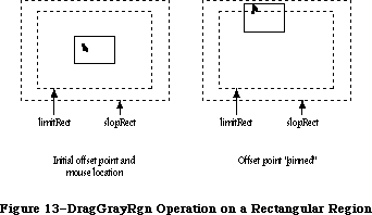 Figure 13–DragGrayRgn Operation on a Rectangular Region
The axis parameter allows you to constrain the region’s motion to only one axis. It has one of the following values:
CONST noConstraint = 0; {no constraint}
hAxisOnly = 1; {horizontal axis only}
vAxisOnly = 2; {vertical axis only}
If an axis constraint is in effect, the outline will follow the mouse’s movements along the specified axis only, ignoring motion along the other axis. With or without an axis constraint, the mouse must still be inside the slop rectangle for the outline to appear at all.
The actionProc parameter is a pointer to a procedure that defines some action to be performed repeatedly for as long as the user holds down the mouse button; the procedure should have no parameters. If actionProc is NIL, DragGrayRgn simply retains control until the mouse button is released.
Assembly-language note: DragGrayRgn calls the procedure pointed to by the
global variable DragHook, if any, as long as the
mouse button is held down. (If there’s an actionProc
procedure, the actionProc procedure is called first.)
If you want the region’s outline to be drawn in a
pattern other than gray, you can store the pattern in
the global variable DragPattern and then invoke the
macro _DragTheRgn.
_______________________________________________________________________________
»Advanced Routines
PROCEDURE GetCWMgrPort (VAR wport: CGrafPtr); [Macintosh II]
The WMgrCPort is a parallel structure to the WMgrPort. The GetCWMgrPort returns the address of the WMgrCPort. In Apple-provided 'WDEF' resources, all drawing is done in the WMgrCPort to allow full color drawing, rather than just the eight QuickDraw colors.
PROCEDURE SetDeskCPat (deskPixPat: PixPatHandle); [Macintosh II]
Note: This routine is not for use by applications, and its description is
only included for informational purposes.
The SetDeskCPat procedure sets the desktop pattern to a given pixel pattern, allowing it to be drawn in more than two colors if desired. The desktop is automatically redrawn in the new pattern. If deskPixPat is an old-style binary pattern (patType = 0), it will be drawn in the current foreground and background colors. If the pixPatHandle is NIL, the standard binary deskPat
('ppat' resource = 16) will be used.
The standard desktop painting routines can paint either in the existing binary pattern (kept in global variable DeskPat) or in a new pixel pattern. The desk pattern used at startup is determined by the value of another bit flag called pCDeskPat. If this is pCDeskPat = 0, the new pixel pattern is used; for all other values, the binary pattern is used by default. The color pattern can be changed through use of the Control Panel or through the use of SetDeskCPat, but only the Control Panel changes the value of pCDeskPat in parameter RAM.
_______________________________________________________________________________
»Low-Level Routines
These routines are called by higher-level routines; normally you won’t need to call them yourself.
FUNCTION CheckUpdate (VAR theEvent: EventRecord) : BOOLEAN;
CheckUpdate is called by the Toolbox Event Manager. From the front to the back in the window list, it looks for a visible window that needs updating (that is, whose update region is not empty). If it finds one whose window record contains a picture handle, it draws the picture (doing all the necessary region manipulation) and looks for the next visible window that needs updating. If it ever finds one whose window record doesn’t contain a picture handle, it stores an update event for that window in theEvent and returns TRUE. If it never finds such a window, it returns FALSE.
PROCEDURE ClipAbove (window: WindowPeek);
ClipAbove sets the clipRgn of the Window Manager port to be the desktop intersected with the current clipRgn, minus the structure regions of all the windows in front of the given window.
Assembly-language note: ClipAbove gets the desktop region from the global
variable GrayRgn.
PROCEDURE SaveOld (window: WindowPeek);
SaveOld saves the given window’s current structure region and content region for the DrawNew operation (see below). It must be balanced by a subsequent call to DrawNew.
PROCEDURE DrawNew (window: WindowPeek; update: BOOLEAN);
If the update parameter is TRUE, DrawNew updates the area
(OldStructure XOR NewStructure) UNION (OldContent XOR NewContent)
where OldStructure and OldContent are the structure and content regions saved by the SaveOld procedure, and NewStructure and NewContent are the current structure and content regions. It erases the area and adds it to the window’s update region. If update is FALSE, it only erases the area.
Warning: In Pascal, SaveOld and DrawNew are not nestable.
Assembly-language note: In assembly language, you can nest SaveOld and
DrawNew if you save and restore the values of the
global variables OldStructure and OldContent.
PROCEDURE PaintOne (window: WindowPeek; clobberedRgn:RgnHandle); [Macintosh II]
PaintOne “paints” the given window, clipped to clobberedRgn and all windows above it: It draws the window frame and, if some content is exposed, erases the exposed area (paints it with the background pattern) and adds it to the window’s update region. If the window parameter is NIL, the window is the desktop and so is painted with the desktop pattern.
The PaintOne routine is modified to improve the performance of updates when differently colored windows are in use. Formerly, the Window Manager collected the update region of multiple windows into a single region, then erased this single region to white. In a color environment, different windows may need to be erased to different colors, so the previously used monochrome optimization is disabled. Each uncovered window is now erased separately, as if the PaintWhite global variable was always set to TRUE. Software that uses the PaintWhite and SaveUpdate flags may appear slightly different when update events are being processed.
PaintOne tests to see if a window has an old or new grafPort, and sets either the wMgrPort or wMgrCPort as appropriate. This allows color windows the full RGB range when being erased to their content color.
Assembly-language note: The global variables SaveUpdate and PaintWhite
are flags used by PaintOne. Normally both flags are
set. Clearing SaveUpdate prevents clobberedRgn from
being added to the window’s update region. Clearing
PaintWhite prevents clobberedRgn from being erased
before being added to the update region (this is
useful, for example, if the background of the window
isn’t the background pattern). The Window Manager
sets both flags periodically, so you should clear
the appropriate flag just before each situation you
wish it to apply to.
PROCEDURE PaintBehind (startWindow: WindowPeek; clobberedRgn: RgnHandle);
PaintBehind calls PaintOne for startWindow and all the windows behind startWindow, clipped to clobberedRgn.
Assembly-language note: PaintBehind clears the global variable PaintWhite
before calling PaintOne, so clobberedRgn isn’t
erased. (PaintWhite is reset after the call to
PaintOne.)
PROCEDURE CalcVis (window: WindowPeek);
CalcVis calculates the visRgn of the given window by starting with its content region and subtracting the structure region of each window in front of it.
PROCEDURE CalcVisBehind (startWindow: WindowPeek; clobberedRgn: RgnHandle);
Assembly-language note: The macro you invoke to call CalcVisBehind from
assembly language is named _CalcVBehind.
CalcVisBehind calculates the visRgns of startWindow and all windows behind startWindow that intersect clobberedRgn. It should be called after PaintBehind.
_______________________________________________________________________________
»DEFINING YOUR OWN WINDOWS
_______________________________________________________________________________
Certain types of windows, such as the standard document window, are predefined for you. However, you may want to define your own type of window—maybe a round or hexagonal window, or even a window shaped like an apple. QuickDraw and the Window Manager make it possible for you to do this.
Note: For the convenience of your application’s user, remember to conform
to the Macintosh User Interface Guidelines for windows as much as
possible.
To define your own type of window, you write a window definition function and store it in a resource file. When you create a window, you provide a window definition ID, which leads to the window definition function. The window definition ID is an integer that contains the resource ID of the window definition function in its upper 12 bits and a variation code in its lower four bits. Thus, for a given resource ID and variation code, the window definition ID is
16 * resource ID + variation code
The variation code allows a single window definition function to implement several related types of window as “variations on a theme”. For example, the dBoxProc type of window is a variation of the standard document window; both use the window definition function whose resource ID is 0, but the document window has a variation code of 0 while the dBoxProc window has a variation code of 1.
The Window Manager calls the Resource Manager to access the window definition function with the given resource ID. The Resource Manager reads the window definition function into memory and returns a handle to it. The Window Manager stores this handle in the windowDefProc field of the window record, along with the variation code in the high-order byte of that field. Later, when it needs to perform a type-dependent action on the window, it calls the window definition function and passes it the variation code as a parameter. Figure 14 illustrates this process.
Figure 13–DragGrayRgn Operation on a Rectangular Region
The axis parameter allows you to constrain the region’s motion to only one axis. It has one of the following values:
CONST noConstraint = 0; {no constraint}
hAxisOnly = 1; {horizontal axis only}
vAxisOnly = 2; {vertical axis only}
If an axis constraint is in effect, the outline will follow the mouse’s movements along the specified axis only, ignoring motion along the other axis. With or without an axis constraint, the mouse must still be inside the slop rectangle for the outline to appear at all.
The actionProc parameter is a pointer to a procedure that defines some action to be performed repeatedly for as long as the user holds down the mouse button; the procedure should have no parameters. If actionProc is NIL, DragGrayRgn simply retains control until the mouse button is released.
Assembly-language note: DragGrayRgn calls the procedure pointed to by the
global variable DragHook, if any, as long as the
mouse button is held down. (If there’s an actionProc
procedure, the actionProc procedure is called first.)
If you want the region’s outline to be drawn in a
pattern other than gray, you can store the pattern in
the global variable DragPattern and then invoke the
macro _DragTheRgn.
_______________________________________________________________________________
»Advanced Routines
PROCEDURE GetCWMgrPort (VAR wport: CGrafPtr); [Macintosh II]
The WMgrCPort is a parallel structure to the WMgrPort. The GetCWMgrPort returns the address of the WMgrCPort. In Apple-provided 'WDEF' resources, all drawing is done in the WMgrCPort to allow full color drawing, rather than just the eight QuickDraw colors.
PROCEDURE SetDeskCPat (deskPixPat: PixPatHandle); [Macintosh II]
Note: This routine is not for use by applications, and its description is
only included for informational purposes.
The SetDeskCPat procedure sets the desktop pattern to a given pixel pattern, allowing it to be drawn in more than two colors if desired. The desktop is automatically redrawn in the new pattern. If deskPixPat is an old-style binary pattern (patType = 0), it will be drawn in the current foreground and background colors. If the pixPatHandle is NIL, the standard binary deskPat
('ppat' resource = 16) will be used.
The standard desktop painting routines can paint either in the existing binary pattern (kept in global variable DeskPat) or in a new pixel pattern. The desk pattern used at startup is determined by the value of another bit flag called pCDeskPat. If this is pCDeskPat = 0, the new pixel pattern is used; for all other values, the binary pattern is used by default. The color pattern can be changed through use of the Control Panel or through the use of SetDeskCPat, but only the Control Panel changes the value of pCDeskPat in parameter RAM.
_______________________________________________________________________________
»Low-Level Routines
These routines are called by higher-level routines; normally you won’t need to call them yourself.
FUNCTION CheckUpdate (VAR theEvent: EventRecord) : BOOLEAN;
CheckUpdate is called by the Toolbox Event Manager. From the front to the back in the window list, it looks for a visible window that needs updating (that is, whose update region is not empty). If it finds one whose window record contains a picture handle, it draws the picture (doing all the necessary region manipulation) and looks for the next visible window that needs updating. If it ever finds one whose window record doesn’t contain a picture handle, it stores an update event for that window in theEvent and returns TRUE. If it never finds such a window, it returns FALSE.
PROCEDURE ClipAbove (window: WindowPeek);
ClipAbove sets the clipRgn of the Window Manager port to be the desktop intersected with the current clipRgn, minus the structure regions of all the windows in front of the given window.
Assembly-language note: ClipAbove gets the desktop region from the global
variable GrayRgn.
PROCEDURE SaveOld (window: WindowPeek);
SaveOld saves the given window’s current structure region and content region for the DrawNew operation (see below). It must be balanced by a subsequent call to DrawNew.
PROCEDURE DrawNew (window: WindowPeek; update: BOOLEAN);
If the update parameter is TRUE, DrawNew updates the area
(OldStructure XOR NewStructure) UNION (OldContent XOR NewContent)
where OldStructure and OldContent are the structure and content regions saved by the SaveOld procedure, and NewStructure and NewContent are the current structure and content regions. It erases the area and adds it to the window’s update region. If update is FALSE, it only erases the area.
Warning: In Pascal, SaveOld and DrawNew are not nestable.
Assembly-language note: In assembly language, you can nest SaveOld and
DrawNew if you save and restore the values of the
global variables OldStructure and OldContent.
PROCEDURE PaintOne (window: WindowPeek; clobberedRgn:RgnHandle); [Macintosh II]
PaintOne “paints” the given window, clipped to clobberedRgn and all windows above it: It draws the window frame and, if some content is exposed, erases the exposed area (paints it with the background pattern) and adds it to the window’s update region. If the window parameter is NIL, the window is the desktop and so is painted with the desktop pattern.
The PaintOne routine is modified to improve the performance of updates when differently colored windows are in use. Formerly, the Window Manager collected the update region of multiple windows into a single region, then erased this single region to white. In a color environment, different windows may need to be erased to different colors, so the previously used monochrome optimization is disabled. Each uncovered window is now erased separately, as if the PaintWhite global variable was always set to TRUE. Software that uses the PaintWhite and SaveUpdate flags may appear slightly different when update events are being processed.
PaintOne tests to see if a window has an old or new grafPort, and sets either the wMgrPort or wMgrCPort as appropriate. This allows color windows the full RGB range when being erased to their content color.
Assembly-language note: The global variables SaveUpdate and PaintWhite
are flags used by PaintOne. Normally both flags are
set. Clearing SaveUpdate prevents clobberedRgn from
being added to the window’s update region. Clearing
PaintWhite prevents clobberedRgn from being erased
before being added to the update region (this is
useful, for example, if the background of the window
isn’t the background pattern). The Window Manager
sets both flags periodically, so you should clear
the appropriate flag just before each situation you
wish it to apply to.
PROCEDURE PaintBehind (startWindow: WindowPeek; clobberedRgn: RgnHandle);
PaintBehind calls PaintOne for startWindow and all the windows behind startWindow, clipped to clobberedRgn.
Assembly-language note: PaintBehind clears the global variable PaintWhite
before calling PaintOne, so clobberedRgn isn’t
erased. (PaintWhite is reset after the call to
PaintOne.)
PROCEDURE CalcVis (window: WindowPeek);
CalcVis calculates the visRgn of the given window by starting with its content region and subtracting the structure region of each window in front of it.
PROCEDURE CalcVisBehind (startWindow: WindowPeek; clobberedRgn: RgnHandle);
Assembly-language note: The macro you invoke to call CalcVisBehind from
assembly language is named _CalcVBehind.
CalcVisBehind calculates the visRgns of startWindow and all windows behind startWindow that intersect clobberedRgn. It should be called after PaintBehind.
_______________________________________________________________________________
»DEFINING YOUR OWN WINDOWS
_______________________________________________________________________________
Certain types of windows, such as the standard document window, are predefined for you. However, you may want to define your own type of window—maybe a round or hexagonal window, or even a window shaped like an apple. QuickDraw and the Window Manager make it possible for you to do this.
Note: For the convenience of your application’s user, remember to conform
to the Macintosh User Interface Guidelines for windows as much as
possible.
To define your own type of window, you write a window definition function and store it in a resource file. When you create a window, you provide a window definition ID, which leads to the window definition function. The window definition ID is an integer that contains the resource ID of the window definition function in its upper 12 bits and a variation code in its lower four bits. Thus, for a given resource ID and variation code, the window definition ID is
16 * resource ID + variation code
The variation code allows a single window definition function to implement several related types of window as “variations on a theme”. For example, the dBoxProc type of window is a variation of the standard document window; both use the window definition function whose resource ID is 0, but the document window has a variation code of 0 while the dBoxProc window has a variation code of 1.
The Window Manager calls the Resource Manager to access the window definition function with the given resource ID. The Resource Manager reads the window definition function into memory and returns a handle to it. The Window Manager stores this handle in the windowDefProc field of the window record, along with the variation code in the high-order byte of that field. Later, when it needs to perform a type-dependent action on the window, it calls the window definition function and passes it the variation code as a parameter. Figure 14 illustrates this process.
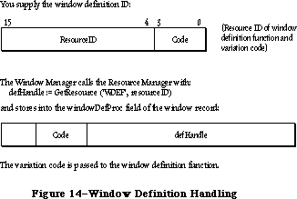 Figure 14–Window Definition Handling
_______________________________________________________________________________
»The Window Definition Function
The window definition function is usually written in assembly language, but may be written in Pascal.
Assembly-language note: The function’s entry point must be at the beginning.
You may choose any name you wish for your window definition function. Here’s how you would declare one named MyWindow:
FUNCTION MyWindow (varCode: INTEGER; theWindow: WindowPtr; message: INTEGER;
param: LONGINT) : LONGINT;
VarCode is the variation code, as described above.
TheWindow indicates the window that the operation will affect. If the window definition function needs to use a WindowPeek type of pointer more than a WindowPtr, you can simply specify WindowPeek instead of WindowPtr in the function declaration.
The message parameter identifies the desired operation. It has one of the following values:
CONST wDraw = 0; {draw window frame}
wHit = 1; {tell what region mouse button was pressed in}
wCalcRgns = 2; {calculate strucRgn and contRgn}
wNew = 3; {do any additional window initialization}
wDispose = 4; {take any additional disposal actions}
wGrow = 5; {draw window's grow image}
wDrawGIcon = 6; {draw size box in content region}
As described below in the discussions of the routines that perform these operations, the value passed for param, the last parameter of the window definition function, depends on the operation. Where it’s not mentioned below, this parameter is ignored. Similarly, the window definition function is expected to return a function result only where indicated; in other cases, the function should return 0.
Note: “Routine” here doesn’t necessarily mean a procedure or function.
While it’s a good idea to set these up as subprograms inside the
window definition function, you’re not required to do so.
_______________________________________________________________________________
»The Draw Window Frame Routine
When the window definition function receives a wDraw message, it should draw the window frame in the current grafPort, which will be the Window Manager port. (For details on drawing, see the QuickDraw chapter.)
This routine should make certain checks to determine exactly what it should do. If the visible field in the window record is FALSE, the routine should do nothing; otherwise, it should examine the value of param received by the window definition function, as described below.
If param is 0, the routine should draw the entire window frame. If the hilited field in the window record is TRUE, the window frame should be highlighted in whatever way is appropriate to show that this is the active window. If goAwayFlag in the window record is also TRUE, the highlighted window frame should include a go-away region; this is useful when you want to define a window such that a particular window of that type may or may not have a go-away region, depending on the situation.
Special action should be taken if the value of param is wInGoAway (a predefined constant, equal to 4, which is one of those returned by the hit routine described below). If param is wInGoAway, the routine should do nothing but
“toggle” the state of the window’s go-away region from unhighlighted to highlighted or vice versa. The highlighting should be whatever is appropriate to show that the mouse button has been pressed inside the region. Simple inverse highlighting may be used or, as in document windows, the appearance of the region may change considerably. In the latter case, the routine could use a “mask” consisting of the unhighlighted state of the region XORed with its highlighted state (where XOR stands for the logical operation “exclusive or”). When such a mask is itself XORed with either state of the region, the result is the other state; Figure 15 illustrates this for a document window.
Figure 14–Window Definition Handling
_______________________________________________________________________________
»The Window Definition Function
The window definition function is usually written in assembly language, but may be written in Pascal.
Assembly-language note: The function’s entry point must be at the beginning.
You may choose any name you wish for your window definition function. Here’s how you would declare one named MyWindow:
FUNCTION MyWindow (varCode: INTEGER; theWindow: WindowPtr; message: INTEGER;
param: LONGINT) : LONGINT;
VarCode is the variation code, as described above.
TheWindow indicates the window that the operation will affect. If the window definition function needs to use a WindowPeek type of pointer more than a WindowPtr, you can simply specify WindowPeek instead of WindowPtr in the function declaration.
The message parameter identifies the desired operation. It has one of the following values:
CONST wDraw = 0; {draw window frame}
wHit = 1; {tell what region mouse button was pressed in}
wCalcRgns = 2; {calculate strucRgn and contRgn}
wNew = 3; {do any additional window initialization}
wDispose = 4; {take any additional disposal actions}
wGrow = 5; {draw window's grow image}
wDrawGIcon = 6; {draw size box in content region}
As described below in the discussions of the routines that perform these operations, the value passed for param, the last parameter of the window definition function, depends on the operation. Where it’s not mentioned below, this parameter is ignored. Similarly, the window definition function is expected to return a function result only where indicated; in other cases, the function should return 0.
Note: “Routine” here doesn’t necessarily mean a procedure or function.
While it’s a good idea to set these up as subprograms inside the
window definition function, you’re not required to do so.
_______________________________________________________________________________
»The Draw Window Frame Routine
When the window definition function receives a wDraw message, it should draw the window frame in the current grafPort, which will be the Window Manager port. (For details on drawing, see the QuickDraw chapter.)
This routine should make certain checks to determine exactly what it should do. If the visible field in the window record is FALSE, the routine should do nothing; otherwise, it should examine the value of param received by the window definition function, as described below.
If param is 0, the routine should draw the entire window frame. If the hilited field in the window record is TRUE, the window frame should be highlighted in whatever way is appropriate to show that this is the active window. If goAwayFlag in the window record is also TRUE, the highlighted window frame should include a go-away region; this is useful when you want to define a window such that a particular window of that type may or may not have a go-away region, depending on the situation.
Special action should be taken if the value of param is wInGoAway (a predefined constant, equal to 4, which is one of those returned by the hit routine described below). If param is wInGoAway, the routine should do nothing but
“toggle” the state of the window’s go-away region from unhighlighted to highlighted or vice versa. The highlighting should be whatever is appropriate to show that the mouse button has been pressed inside the region. Simple inverse highlighting may be used or, as in document windows, the appearance of the region may change considerably. In the latter case, the routine could use a “mask” consisting of the unhighlighted state of the region XORed with its highlighted state (where XOR stands for the logical operation “exclusive or”). When such a mask is itself XORed with either state of the region, the result is the other state; Figure 15 illustrates this for a document window.
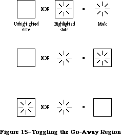 Figure 15–Toggling the Go-Away Region
Typically the window frame will include the window’s title, which should be in the system font and system font size. The Window Manager port will already be set to use the system font and system font size.
Note: Nothing drawn outside the window’s structure region will be visible.
_______________________________________________________________________________
»The Hit Routine
When the window definition function receives a wHit message, it also receives as its param value the point where the mouse button was pressed. This point is given in global coordinates, with the vertical coordinate in the high-order word of the long integer and the horizontal coordinate in the low-order word. The window definition function should determine where the mouse button “hit” and then return one of these predefined constants:
CONST wNoHit = 0; {none of the following}
wInContent = 1; {in content region (except grow, if active)}
wInDrag = 2; {in drag region}
wInGrow = 3; {in grow region (active window only)}
wInGoAway = 4; {in go-away region (active window only)}
Usually, wNoHit means the given point isn’t anywhere within the window, but this is not necessarily so. For example, the document window’s hit routine returns wNoHit if the point is in the window frame but not in the title bar.
The constants wInGrow and wInGoAway should be returned only if the window is active, since by convention the size box and go-away region won’t be drawn if the window is inactive (or, if drawn, won’t be operable). In an inactive document window, if the mouse button is pressed in the title bar where the close box would be if the window were active, the hit routine returns wInDrag.
Of the regions that may have been hit, only the content region necessarily has the structure of a region and is included in the window record. The hit routine can determine in any way it likes whether the drag, grow, or go-away “region” has been hit.
_______________________________________________________________________________
»The Routine to Calculate Regions
The routine executed in response to a wCalcRgns message should calculate the window’s structure region and content region based on the current grafPort’s portRect. These regions, whose handles are in the strucRgn and contRgn fields, are in global coordinates. The Window Manager will request this operation only if the window is visible.
Warning: When you calculate regions for your own type of window, do not
alter the clipRgn or the visRgn of the window’s grafPort. The
Window Manager and QuickDraw take care of this for you. Altering
the clipRgn or visRgn may result in damage to other windows.
_______________________________________________________________________________
»The Initialize Routine
After initializing fields as appropriate when creating a new window, the Window Manager sends the message wNew to the window definition function. This gives the definition function a chance to perform any type-specific initialization it may require. For example, if the content region is unusually shaped, the initialize routine might allocate space for the region and store the region handle in the dataHandle field of the window record. The initialize routine for a standard document window does nothing.
_______________________________________________________________________________
»The Dispose Routine
The Window Manager’s CloseWindow and DisposeWindow procedures send the message wDispose to the window definition function, telling it to carry out any additional actions required when disposing of the window. The dispose routine might, for example, release space that was allocated by the initialize routine. The dispose routine for a standard document window does nothing.
_______________________________________________________________________________
»The Grow Routine
When the window definition function receives a wGrow message, it also receives a pointer to a rectangle as its param value. The rectangle is in global coordinates and is usually aligned at its top left corner with the portRect of the window’s grafPort. The grow routine should draw a grow image of the window to fit the given rectangle (that is, whatever is appropriate to show that the window’s size will change, such as an outline of the content region). The Window Manager requests this operation repeatedly as the user drags inside the grow region. The grow routine should draw in the current grafPort, which will be the Window Manager port, and should use the grafPort’s current pen pattern and pen mode, which are set up (as gray and notPatXor) to conform to the Macintosh User Interface Guidelines.
The grow routine for a standard document window draws a dotted (gray) outline of the window and also the lines delimiting the title bar, size box, and scroll bar areas.
_______________________________________________________________________________
»The Draw Size Box Routine
If the window’s grow region is in the content region, the wDrawGIcon message tells the window definition function to draw the size box in the grow region if the window is active (highlighted); if the window is inactive it should draw whatever is appropriate to show that the window temporarily can’t be sized. For active document windows, this routine draws the size box icon in the bottom right corner of the portRect of the window’s grafPort, along with the lines delimiting the size box and scroll bar areas; for inactive windows, it draws just the delimiting lines, and erases the size box icon.
If the grow region is located in the window frame rather than the content region, this routine should do nothing.
_______________________________________________________________________________
»The Color Definition Procedure
Like standard windows, custom window structures can be drawn in full color. On the Macintosh II, a new data structure known as the WMgrCPort, which opens a cGrafPort, is introduced. This data structure is analogous to the existing WMgrPort, and defines the desktop area of the Window Manager, allowing desktop objects (such as window frames) to be drawn in full color. The standard defprocs included in the Macintosh II ROM and on the system disk, are universal defprocs—that is, they support the full color capabilities of the Macintosh II while maintaining full compatibility on noncolor Macintoshes. Since applications can be transported between color and noncolor Macintoshes on disk, custom defprocs associated with applications should be written in this same universal style.
To write a universal defproc, the defproc should, upon entry, identify the capabilities of the machine on which it is running by using the _SysEnvirons call. If the machine doesn’t support color, then all previous rules for writing defprocs should be followed.
If the machine is equipped with Color QuickDraw, then a number of extra steps should be performed:
• First, the defproc should change the current port from the WMgrPort to
the WMgrCPort, to allow the system to draw in the full range of RGBColors.
• Next, the defproc should update certain fields in the WMgrCPort to the
values of the corresponding fields in the WMgrPort. The fields that
should be updated are the pen attributes, the text attributes, and bkPat.
The vis and clip regions are automatically transferred by the Window
Manager.
Note: The parallelism of the WMgrPort and the WMgrCPort is maintained only
by the defprocs. All defprocs that draw in the WMgrPort should follow
these rules even if the changed fields don’t affect their operation.
When the two ports are in parallel, the color defproc can proceed with its drawing. Note that the GetAuxWin routine, described above, can be used to get the intended colors for the window parts from the AuxWinList. As with all color objects, highlighting shouldn’t be performed by inverting; the forecolor and backcolor should be reversed and the highlighted item redrawn. No special steps need be taken on exit from the defproc. All other features and requirements of defprocs are unchanged.
Note: For compatibility with systems using MultiFinder™, no drawing should
take place in either the WMgrPort or the WMgrCPort unless the drawing
occurs within a definition procedure.
_______________________________________________________________________________
»FORMATS OF RESOURCES FOR WINDOWS
_______________________________________________________________________________
The Window Manager function GetNewWindow takes the resource ID of a window template as a parameter, and gets from the template the same information that the NewWindow function gets from six of its parameters. The resource type for a window template is 'WIND', and the resource data has the following format:
Number of bytes Contents
8 bytes Same as boundsRect parameter to NewWindow
2 bytes Same as procID parameter to NewWindow
2 bytes Same as visible parameter to NewWindow
2 bytes Same as goAwayFlag parameter to NewWindow
4 bytes Same as refCon parameter to NewWindow
n bytes Same as title parameter to NewWindow
(1-byte length in bytes, followed by the
characters of the title)
The resource type for a window definition function is 'WDEF', and the resource data is simply the compiled or assembled code of the function.
_______________________________________________________________________________
»SUMMARY OF THE WINDOW MANAGER
_______________________________________________________________________________
Constants
CONST
{ Window definition IDs }
documentProc = 0; {standard document window}
dBoxProc = 1; {alert box or modal dialog box}
plainDBox = 2; {plain box}
altDBoxProc = 3; {plain box with shadow}
noGrowDocProc = 4; {document window without size box}
rDocProc = 16; {rounded-corner window}
{ Window class, in windowKind field of window record }
dialogKind = 2; {dialog or alert window}
userKind = 8; {window created directly by the application}
{ Values returned by FindWindow }
inDesk = 0; {none of the following}
inMenuBar = 1; {in menu bar}
inSysWindow = 2; {in system window}
inContent = 3; {in content region (except grow, if active)}
inDrag = 4; {in drag region}
inGrow = 5; {in grow region (active window only)}
inGoAway = 6; {in go-away region (active window only)}
inZoomIn = 7; {in zoom box for zooming in}
inZoomOut = 8; {in zoom box for zooming out}
{ Axis constraints for DragGrayRgn }
noConstraint = 0; {no constraint}
hAxisOnly = 1; {horizontal axis only}
vAxisOnly = 2; {vertical axis only}
{ Messages to window definition function }
wDraw = 0; {draw window frame}
wHit = 1; {tell what region mouse button was pressed in}
wCalcRgns = 2; {calculate strucRgn and contRgn}
wNew = 3; {do any additional window initialization}
wDispose = 4; {take any additional disposal actions}
wGrow = 5; {draw window's grow image}
wDrawGIcon = 6; {draw size box in content region}
{ Values returned by window definition function's hit routine }
wNoHit = 0; {none of the following}
wInContent = 1; {in content region (except grow, if active)}
wInDrag = 2; {in drag region}
wInGrow = 3; {in grow region (active window only)}
wInGoAway = 4; {in go-away region (active window only)}
wInZoomIn = 5; {in zoom box for zooming in}
wInZoomOut = 6; {in zoom box for zooming out}
{ Resource ID of desktop pattern }
deskPatID = 16;
{ Window Part Identifiers which correlate color table entries }
{ with window elements }
wContentColor = 0;
wFrameColor = 1;
wTextColor = 2;
wHiliteColor = 3;
wTitleBarColor = 4;
_______________________________________________________________________________
Data Types
TYPE
WindowPtr = GrafPtr;
WindowPeek = ^WindowRecord;
WindowRecord = RECORD
port: GrafPort; {window's grafPort}
windowKind: INTEGER; {window class}
visible: BOOLEAN; {TRUE if visible}
hilited: BOOLEAN; {TRUE if highlighted}
goAwayFlag: BOOLEAN; {TRUE if has go-away region}
spareFlag: BOOLEAN; {reserved for future use}
strucRgn: RgnHandle; {structure region}
contRgn: RgnHandle; {content region}
updateRgn: RgnHandle; {update region}
windowDefProc: Handle; {window definition function}
dataHandle: Handle; {data used by windowDefProc}
titleHandle: StringHandle;{window's title}
titleWidth: INTEGER; {width of title in pixels}
controlList: ControlHandle; {window's control list}
nextWindow: WindowPeek; {next window in window list}
windowPic: PicHandle; {picture for drawing window}
refCon: LONGINT {window's reference value}
END;
WStateData = RECORD;
userState: Rect;
stdState: Rect
END;
CWindowPtr = CGrafPtr;
CWindowPeek = ^CWindowRecord;
CWindowRecord = RECORD {all fields remain the same as before}
port: CGrafPort; {window's CGrafPort}
windowKind: INTEGER; {window class}
visible: BOOLEAN; {TRUE if visible}
hilited: BOOLEAN; {TRUE if highlighted}
goAwayFlag: BOOLEAN; {TRUE if has go-away region}
spareFlag: BOOLEAN; {reserved for future use}
strucRgn: RgnHandle; {structure region}
contRgn: RgnHandle; {content region}
updateRgn: RgnHandle; {update region}
windowDefProc: Handle; {window definition function}
dataHandle: Handle; {data used by windowDefProc}
titleHandle: StringHandle; {window's title}
titleWidth: INTEGER; {width of title in pixels}
controlList: ControlHandle; {window's control list}
nextWindow: CWindowPeek; {next window in window list}
windowPic: PicHandle; {picture for drawing window}
refCon: LONGINT {window's reference value}
END;
AuxWinHandle = ^AuxWinPtr;
AuxWinPtr = ^AuxWinRec;
AuxWinRec = RECORD
awNext: AuxWinHandle; {handle to next record in list}
awOwner: WindowPtr; {pointer to owning window}
awCTable: CTabHandle; {handle to window's color table}
dialogCItem: Handle; {private storage for }
{ Dialog Manager}
awFlags: LONGINT; {reserved for future use}
awReserved: CTabHandle; {reserved for future use}
awRefCon: LONGINT {reserved for }
{ application use}
END;
WCTabHandle = ^WCTabPtr;
WCTabPtr = ^WinCTab;
WinCTab = RECORD
wCSeed: LONGINT; {unique identifier from table}
wCReserved: INTEGER; {not used for windows}
ctSize: INTEGER; {number of entries in table –1}
ctTable: Array [0..4] of ColorSpec; {array of }
{ ColorSpec records}
END;
_______________________________________________________________________________
Routines
Initialization and Allocation
PROCEDURE InitWindows;
PROCEDURE GetWMgrPort (VAR wPort: GrafPtr);
FUNCTION NewWindow (wStorage: Ptr; boundsRect: Rect; title: Str255;
visible: BOOLEAN; procID: INTEGER;
behind: WindowPtr; goAwayFlag: BOOLEAN;
refCon: LONGINT) : WindowPtr;
FUNCTION GetNewWindow (windowID: INTEGER; wStorage: Ptr;
behind: WindowPtr) : WindowPtr;
PROCEDURE CloseWindow (theWindow: WindowPtr);
PROCEDURE DisposeWindow (theWindow: WindowPtr);
Window Display
PROCEDURE SetWTitle (theWindow: WindowPtr; title: Str255);
PROCEDURE GetWTitle (theWindow: WindowPtr; VAR title: Str255);
PROCEDURE SelectWindow (theWindow: WindowPtr);
PROCEDURE HideWindow (theWindow: WindowPtr);
PROCEDURE ShowWindow (theWindow: WindowPtr);
PROCEDURE ShowHide (theWindow: WindowPtr; showFlag: BOOLEAN);
PROCEDURE HiliteWindow (theWindow: WindowPtr; fHilite: BOOLEAN);
PROCEDURE BringToFront (theWindow: WindowPtr);
PROCEDURE SendBehind (theWindow,behindWindow: WindowPtr);
FUNCTION FrontWindow : WindowPtr;
PROCEDURE DrawGrowIcon (theWindow: WindowPtr);
Mouse Location
FUNCTION FindWindow (thePt: Point; VAR whichWindow: WindowPtr) : INTEGER;
FUNCTION TrackGoAway (theWindow: WindowPtr; thePt: Point) : BOOLEAN;
Window Movement and Sizing
PROCEDURE MoveWindow (theWindow: WindowPtr; hGlobal,vGlobal: INTEGER;
front: BOOLEAN);
PROCEDURE DragWindow (theWindow: WindowPtr; startPt: Point;
boundsRect: Rect);
FUNCTION GrowWindow (theWindow: WindowPtr; startPt: Point;
sizeRect: Rect) : LONGINT;
PROCEDURE SizeWindow (theWindow: WindowPtr; w,h: INTEGER; fUpdate: BOOLEAN);
FUNCTION TrackBox (theWindow: WindowPtr; thePt: Point;
partCode: INTEGER) : BOOLEAN;
PROCEDURE ZoomWindow (theWindow: WindowPtr; partCode: INTEGER;
front: BOOLEAN);
Update Region Maintenance
PROCEDURE InvalRect (badRect: Rect);
PROCEDURE InvalRgn (badRgn: RgnHandle);
PROCEDURE ValidRect (goodRect: Rect);
PROCEDURE ValidRgn (goodRgn: RgnHandle);
PROCEDURE BeginUpdate (theWindow: WindowPtr);
PROCEDURE EndUpdate (theWindow: WindowPtr);
Color Window Routines
FUNCTION NewCWindow (wStorage: Ptr; boundsRect: Rect; title: Str255;
visible: BOOLEAN; procID: INTEGER; behind: WindowPtr;
goAwayFlag: BOOLEAN; refCon: LONGINT) : WindowPtr;
FUNCTION GetNewCWindow (windowID: INTEGER; wStorage: Ptr;
behind: CWindowPtr) : WindowPtr;
PROCEDURE SetWinColor (theWindow: WindowPtr; newColorTable: WCTabHandle);
FUNCTION GetAuxWin (theWindow: WindowPtr;
VAR awHndl: AuxWinHandle) : BOOLEAN;
FUNCTION GetWVariant (whichWindow:WindowPtr): INTEGER;
FUNCTION GetGrayRgn : regionHandle; [Not in ROM]
Miscellaneous Routines
PROCEDURE SetWRefCon (theWindow: WindowPtr; data: LONGINT);
FUNCTION GetWRefCon (theWindow: WindowPtr) : LONGINT;
PROCEDURE SetWindowPic (theWindow: WindowPtr; pic: PicHandle);
FUNCTION GetWindowPic (theWindow: WindowPtr) : PicHandle;
FUNCTION PinRect (theRect: Rect; thePt: Point) : LONGINT;
FUNCTION DragGrayRgn (theRgn: RgnHandle; startPt: Point;
lmitRect, slopRect: Rect; axis: INTEGER;
actionProc: ProcPtr) : LONGINT;
Advanced Routines
PROCEDURE GetCWMgrPort (VAR wport: CGrafPtr);
PROCEDURE SetDeskCPat (deskPixPat: PixPatHandle);
Low-Level Routines
FUNCTION CheckUpdate (VAR theEvent: EventRecord) : BOOLEAN;
PROCEDURE ClipAbove (window: WindowPeek);
PROCEDURE SaveOld (window: WindowPeek);
PROCEDURE DrawNew (window: WindowPeek; update: BOOLEAN);
PROCEDURE PaintOne (window: WindowPeek; clobberedRgn: RgnHandle);
PROCEDURE PaintBehind (startWindow: WindowPeek; clobberedRgn: RgnHandle);
PROCEDURE CalcVis (window: WindowPeek);
PROCEDURE CalcVisBehind (startWindow: WindowPeek; clobberedRgn: RgnHandle);
_______________________________________________________________________________
Diameters of Curvature for Rounded-Corner Windows
Window definition ID Diameters of curvature
rDocProc 16, 16
rDocProc + 1 4, 4
rDocProc + 2 6, 6
rDocProc + 3 8, 8
rDocProc + 4 10, 10
rDocProc + 5 12, 12
rDocProc + 6 20, 20
rDocProc + 7 24, 24
_______________________________________________________________________________
Window Definition Function
FUNCTION MyWindow (varCode: INTEGER; theWindow: WindowPtr;
message: INTEGER; param: LONGINT) : LONGINT;
_______________________________________________________________________________
Variables
GrayRgn {Contains information on size and shape of the current desktop}
AuxWinHead {Contains handle to the head of the auxiliary window list}
_______________________________________________________________________________
Assembly-Language Information
Constants
; Window definition IDs
documentProc .EQU 0 ;standard document window
dBoxProc .EQU 1 ;alert box or modal dialog box
plainDBox .EQU 2 ;plain box
altDBoxProc .EQU 3 ;plain box with shadow
noGrowDocProc .EQU 4 ;document window without size box
rDocProc .EQU 16 ;rounded-corner window
; Window class, in windowKind field of window record
dialogKind .EQU 2 ;dialog or alert window
userKind .EQU 8 ;window created directly by the application
; Values returned by FindWindow
inDesk .EQU 0 ;none of the following
inMenuBar .EQU 1 ;in menu bar
inSysWindow .EQU 2 ;in system window
inContent .EQU 3 ;in content region (except grow, if active)
inDrag .EQU 4 ;in drag region
inGrow .EQU 5 ;in grow region (active window only)
inGoAway .EQU 6 ;in go-away region (active window only)
inZoomIn .EQU 7 ;in zoom box for zooming in
inZoomOut .EQU 8 ;in zoom box for zooming out
; Axis constraints for DragGrayRgn
noConstraint .EQU 0 ;no constraint
hAxisOnly .EQU 1 ;horizontal axis only
vAxisOnly .EQU 2 ;vertical axis only
; Messages to window definition function
wDrawMsg .EQU 0 ;draw window frame
wHitMsg .EQU 1 ;tell what region mouse button was pressed in
wCalcRgnMsg .EQU 2 ;calculate strucRgn and contRgn
wInitMsg .EQU 3 ;do any additional window initialization
wDisposeMsg .EQU 4 ;take any additional disposal actions
wGrowMsg .EQU 5 ;draw window's grow image
wGIconMsg .EQU 6 ;draw size box in content region
; Value returned by window definition function's hit routine
wNoHit .EQU 0 ;none of the following
wInContent .EQU 1 ;in content region (except grow, if active)
wInDrag .EQU 2 ;in drag region
wInGrow .EQU 3 ;in grow region (active window only)
wInGoAway .EQU 4 ;in go-away region (active window only)
wInZoomIn .EQU 5 ;in zoom box for zooming in
wInZoomOut .EQU 6 ;in zoom box for zooming out
; Resource ID of desktop pattern
deskPatID .EQU 16
; Window Part Identifiers that correlate color table entries with
; window elements
wContentColor EQU 0
wFrameColor EQU 1
wTextColor EQU 2
wHiliteColor EQU 3
wTitleBarColor EQU 4
; auxWinRec structure
nextAuxWin EQU $0 ;next in chain [Handle]
auxWinOwner EQU $4 ;owner ID [WindowPtr]
awCTable EQU $8 ;color table [CTabHandle]
dialogCItem EQU $C ;handle to dialog manager structures [handle]
awFlags EQU $10 ;handle for QuickDraw [handle]
awResrv EQU $14 ;for expansion [longint]
awRefCon EQU $18 ;user constant [longint]
; Global variables
AuxWinHead EQU $0CD0 ;[handle] Window Aux List head
GrayRgn EQU $9EE ;contains information on size and shape
; of the current desktop
Window Record Data Structure
windowPort Window’s grafPort (portRec bytes)
windowKind Window class (word)
wVisible Nonzero if window is visible (byte)
wHilited Nonzero if window is highlighted (byte)
wGoAway Nonzero if window has go-away region (byte)
wZoom Nonzero if window has a zoom-window box (byte)
structRgn Handle to structure region of window
contRgn Handle to content region of window
updateRgn Handle to update region of window
windowDef Handle to window definition function
wDataHandle Handle to standard and user window states
wTitleHandle Handle to window’s title (preceded by length)
wTitleWidth Width of title in pixels (word)
wControlList Handle to window’s control list
nextWindow Pointer to next window in window list
windowPic Picture handle for drawing window
wRefCon Window’s reference value (long)
windowSize Size in bytes of window record
Window State Data Structure
userState Window’s user state (rectangle; 8 bytes)
stdState Window’s standard state (rectangle; 8 bytes)
Special Macro Names
Pascal name Macro name
CalcVisBehind _CalcVBehind
DisposeWindow _DisposWindow
DragGrayRgn _DragGrayRgn or, after setting the global variable
DragPattern, _DragTheRgn
Variables
WindowList Pointer to first window in window list
SaveUpdate Flag for whether to generate update events (word)
PaintWhite Flag for whether to paint window white before update event (word)
CurActivate Pointer to window to receive activate event
CurDeactive Pointer to window to receive deactivate event
GrayRgn Handle to region drawn as desktop
DeskPattern Pattern with which desktop is painted (8 bytes)
DeskHook Address of procedure for painting desktop or
responding to clicks on desktop
WMgrPort Pointer to Window Manager port
GhostWindow Pointer to window never to be considered frontmost
DragHook Address of procedure to execute during TrackGoAway,
DragWindow, GrowWindow, and DragGrayRgn
DragPattern Pattern of dragged region’s outline (8 bytes)
OldStructure Handle to saved structure region
OldContent Handle to saved content region
SaveVisRgn Handle to saved visRgn
Further Reference:
_______________________________________________________________________________
QuickDraw
Color QuickDraw
Toolbox Event Manager
Resource Manager
Technical Note #53, MoreMasters Revisited
Technical Note #79, ZoomWindow
Technical Note #117, Compatibility: Why & How
Technical Note #194, WMgrPortability
Technical Note #212, The Joy Of Being 32-Bit Clean
Technical Note #256, Stand-Alone Code, ad nauseam
Figure 15–Toggling the Go-Away Region
Typically the window frame will include the window’s title, which should be in the system font and system font size. The Window Manager port will already be set to use the system font and system font size.
Note: Nothing drawn outside the window’s structure region will be visible.
_______________________________________________________________________________
»The Hit Routine
When the window definition function receives a wHit message, it also receives as its param value the point where the mouse button was pressed. This point is given in global coordinates, with the vertical coordinate in the high-order word of the long integer and the horizontal coordinate in the low-order word. The window definition function should determine where the mouse button “hit” and then return one of these predefined constants:
CONST wNoHit = 0; {none of the following}
wInContent = 1; {in content region (except grow, if active)}
wInDrag = 2; {in drag region}
wInGrow = 3; {in grow region (active window only)}
wInGoAway = 4; {in go-away region (active window only)}
Usually, wNoHit means the given point isn’t anywhere within the window, but this is not necessarily so. For example, the document window’s hit routine returns wNoHit if the point is in the window frame but not in the title bar.
The constants wInGrow and wInGoAway should be returned only if the window is active, since by convention the size box and go-away region won’t be drawn if the window is inactive (or, if drawn, won’t be operable). In an inactive document window, if the mouse button is pressed in the title bar where the close box would be if the window were active, the hit routine returns wInDrag.
Of the regions that may have been hit, only the content region necessarily has the structure of a region and is included in the window record. The hit routine can determine in any way it likes whether the drag, grow, or go-away “region” has been hit.
_______________________________________________________________________________
»The Routine to Calculate Regions
The routine executed in response to a wCalcRgns message should calculate the window’s structure region and content region based on the current grafPort’s portRect. These regions, whose handles are in the strucRgn and contRgn fields, are in global coordinates. The Window Manager will request this operation only if the window is visible.
Warning: When you calculate regions for your own type of window, do not
alter the clipRgn or the visRgn of the window’s grafPort. The
Window Manager and QuickDraw take care of this for you. Altering
the clipRgn or visRgn may result in damage to other windows.
_______________________________________________________________________________
»The Initialize Routine
After initializing fields as appropriate when creating a new window, the Window Manager sends the message wNew to the window definition function. This gives the definition function a chance to perform any type-specific initialization it may require. For example, if the content region is unusually shaped, the initialize routine might allocate space for the region and store the region handle in the dataHandle field of the window record. The initialize routine for a standard document window does nothing.
_______________________________________________________________________________
»The Dispose Routine
The Window Manager’s CloseWindow and DisposeWindow procedures send the message wDispose to the window definition function, telling it to carry out any additional actions required when disposing of the window. The dispose routine might, for example, release space that was allocated by the initialize routine. The dispose routine for a standard document window does nothing.
_______________________________________________________________________________
»The Grow Routine
When the window definition function receives a wGrow message, it also receives a pointer to a rectangle as its param value. The rectangle is in global coordinates and is usually aligned at its top left corner with the portRect of the window’s grafPort. The grow routine should draw a grow image of the window to fit the given rectangle (that is, whatever is appropriate to show that the window’s size will change, such as an outline of the content region). The Window Manager requests this operation repeatedly as the user drags inside the grow region. The grow routine should draw in the current grafPort, which will be the Window Manager port, and should use the grafPort’s current pen pattern and pen mode, which are set up (as gray and notPatXor) to conform to the Macintosh User Interface Guidelines.
The grow routine for a standard document window draws a dotted (gray) outline of the window and also the lines delimiting the title bar, size box, and scroll bar areas.
_______________________________________________________________________________
»The Draw Size Box Routine
If the window’s grow region is in the content region, the wDrawGIcon message tells the window definition function to draw the size box in the grow region if the window is active (highlighted); if the window is inactive it should draw whatever is appropriate to show that the window temporarily can’t be sized. For active document windows, this routine draws the size box icon in the bottom right corner of the portRect of the window’s grafPort, along with the lines delimiting the size box and scroll bar areas; for inactive windows, it draws just the delimiting lines, and erases the size box icon.
If the grow region is located in the window frame rather than the content region, this routine should do nothing.
_______________________________________________________________________________
»The Color Definition Procedure
Like standard windows, custom window structures can be drawn in full color. On the Macintosh II, a new data structure known as the WMgrCPort, which opens a cGrafPort, is introduced. This data structure is analogous to the existing WMgrPort, and defines the desktop area of the Window Manager, allowing desktop objects (such as window frames) to be drawn in full color. The standard defprocs included in the Macintosh II ROM and on the system disk, are universal defprocs—that is, they support the full color capabilities of the Macintosh II while maintaining full compatibility on noncolor Macintoshes. Since applications can be transported between color and noncolor Macintoshes on disk, custom defprocs associated with applications should be written in this same universal style.
To write a universal defproc, the defproc should, upon entry, identify the capabilities of the machine on which it is running by using the _SysEnvirons call. If the machine doesn’t support color, then all previous rules for writing defprocs should be followed.
If the machine is equipped with Color QuickDraw, then a number of extra steps should be performed:
• First, the defproc should change the current port from the WMgrPort to
the WMgrCPort, to allow the system to draw in the full range of RGBColors.
• Next, the defproc should update certain fields in the WMgrCPort to the
values of the corresponding fields in the WMgrPort. The fields that
should be updated are the pen attributes, the text attributes, and bkPat.
The vis and clip regions are automatically transferred by the Window
Manager.
Note: The parallelism of the WMgrPort and the WMgrCPort is maintained only
by the defprocs. All defprocs that draw in the WMgrPort should follow
these rules even if the changed fields don’t affect their operation.
When the two ports are in parallel, the color defproc can proceed with its drawing. Note that the GetAuxWin routine, described above, can be used to get the intended colors for the window parts from the AuxWinList. As with all color objects, highlighting shouldn’t be performed by inverting; the forecolor and backcolor should be reversed and the highlighted item redrawn. No special steps need be taken on exit from the defproc. All other features and requirements of defprocs are unchanged.
Note: For compatibility with systems using MultiFinder™, no drawing should
take place in either the WMgrPort or the WMgrCPort unless the drawing
occurs within a definition procedure.
_______________________________________________________________________________
»FORMATS OF RESOURCES FOR WINDOWS
_______________________________________________________________________________
The Window Manager function GetNewWindow takes the resource ID of a window template as a parameter, and gets from the template the same information that the NewWindow function gets from six of its parameters. The resource type for a window template is 'WIND', and the resource data has the following format:
Number of bytes Contents
8 bytes Same as boundsRect parameter to NewWindow
2 bytes Same as procID parameter to NewWindow
2 bytes Same as visible parameter to NewWindow
2 bytes Same as goAwayFlag parameter to NewWindow
4 bytes Same as refCon parameter to NewWindow
n bytes Same as title parameter to NewWindow
(1-byte length in bytes, followed by the
characters of the title)
The resource type for a window definition function is 'WDEF', and the resource data is simply the compiled or assembled code of the function.
_______________________________________________________________________________
»SUMMARY OF THE WINDOW MANAGER
_______________________________________________________________________________
Constants
CONST
{ Window definition IDs }
documentProc = 0; {standard document window}
dBoxProc = 1; {alert box or modal dialog box}
plainDBox = 2; {plain box}
altDBoxProc = 3; {plain box with shadow}
noGrowDocProc = 4; {document window without size box}
rDocProc = 16; {rounded-corner window}
{ Window class, in windowKind field of window record }
dialogKind = 2; {dialog or alert window}
userKind = 8; {window created directly by the application}
{ Values returned by FindWindow }
inDesk = 0; {none of the following}
inMenuBar = 1; {in menu bar}
inSysWindow = 2; {in system window}
inContent = 3; {in content region (except grow, if active)}
inDrag = 4; {in drag region}
inGrow = 5; {in grow region (active window only)}
inGoAway = 6; {in go-away region (active window only)}
inZoomIn = 7; {in zoom box for zooming in}
inZoomOut = 8; {in zoom box for zooming out}
{ Axis constraints for DragGrayRgn }
noConstraint = 0; {no constraint}
hAxisOnly = 1; {horizontal axis only}
vAxisOnly = 2; {vertical axis only}
{ Messages to window definition function }
wDraw = 0; {draw window frame}
wHit = 1; {tell what region mouse button was pressed in}
wCalcRgns = 2; {calculate strucRgn and contRgn}
wNew = 3; {do any additional window initialization}
wDispose = 4; {take any additional disposal actions}
wGrow = 5; {draw window's grow image}
wDrawGIcon = 6; {draw size box in content region}
{ Values returned by window definition function's hit routine }
wNoHit = 0; {none of the following}
wInContent = 1; {in content region (except grow, if active)}
wInDrag = 2; {in drag region}
wInGrow = 3; {in grow region (active window only)}
wInGoAway = 4; {in go-away region (active window only)}
wInZoomIn = 5; {in zoom box for zooming in}
wInZoomOut = 6; {in zoom box for zooming out}
{ Resource ID of desktop pattern }
deskPatID = 16;
{ Window Part Identifiers which correlate color table entries }
{ with window elements }
wContentColor = 0;
wFrameColor = 1;
wTextColor = 2;
wHiliteColor = 3;
wTitleBarColor = 4;
_______________________________________________________________________________
Data Types
TYPE
WindowPtr = GrafPtr;
WindowPeek = ^WindowRecord;
WindowRecord = RECORD
port: GrafPort; {window's grafPort}
windowKind: INTEGER; {window class}
visible: BOOLEAN; {TRUE if visible}
hilited: BOOLEAN; {TRUE if highlighted}
goAwayFlag: BOOLEAN; {TRUE if has go-away region}
spareFlag: BOOLEAN; {reserved for future use}
strucRgn: RgnHandle; {structure region}
contRgn: RgnHandle; {content region}
updateRgn: RgnHandle; {update region}
windowDefProc: Handle; {window definition function}
dataHandle: Handle; {data used by windowDefProc}
titleHandle: StringHandle;{window's title}
titleWidth: INTEGER; {width of title in pixels}
controlList: ControlHandle; {window's control list}
nextWindow: WindowPeek; {next window in window list}
windowPic: PicHandle; {picture for drawing window}
refCon: LONGINT {window's reference value}
END;
WStateData = RECORD;
userState: Rect;
stdState: Rect
END;
CWindowPtr = CGrafPtr;
CWindowPeek = ^CWindowRecord;
CWindowRecord = RECORD {all fields remain the same as before}
port: CGrafPort; {window's CGrafPort}
windowKind: INTEGER; {window class}
visible: BOOLEAN; {TRUE if visible}
hilited: BOOLEAN; {TRUE if highlighted}
goAwayFlag: BOOLEAN; {TRUE if has go-away region}
spareFlag: BOOLEAN; {reserved for future use}
strucRgn: RgnHandle; {structure region}
contRgn: RgnHandle; {content region}
updateRgn: RgnHandle; {update region}
windowDefProc: Handle; {window definition function}
dataHandle: Handle; {data used by windowDefProc}
titleHandle: StringHandle; {window's title}
titleWidth: INTEGER; {width of title in pixels}
controlList: ControlHandle; {window's control list}
nextWindow: CWindowPeek; {next window in window list}
windowPic: PicHandle; {picture for drawing window}
refCon: LONGINT {window's reference value}
END;
AuxWinHandle = ^AuxWinPtr;
AuxWinPtr = ^AuxWinRec;
AuxWinRec = RECORD
awNext: AuxWinHandle; {handle to next record in list}
awOwner: WindowPtr; {pointer to owning window}
awCTable: CTabHandle; {handle to window's color table}
dialogCItem: Handle; {private storage for }
{ Dialog Manager}
awFlags: LONGINT; {reserved for future use}
awReserved: CTabHandle; {reserved for future use}
awRefCon: LONGINT {reserved for }
{ application use}
END;
WCTabHandle = ^WCTabPtr;
WCTabPtr = ^WinCTab;
WinCTab = RECORD
wCSeed: LONGINT; {unique identifier from table}
wCReserved: INTEGER; {not used for windows}
ctSize: INTEGER; {number of entries in table –1}
ctTable: Array [0..4] of ColorSpec; {array of }
{ ColorSpec records}
END;
_______________________________________________________________________________
Routines
Initialization and Allocation
PROCEDURE InitWindows;
PROCEDURE GetWMgrPort (VAR wPort: GrafPtr);
FUNCTION NewWindow (wStorage: Ptr; boundsRect: Rect; title: Str255;
visible: BOOLEAN; procID: INTEGER;
behind: WindowPtr; goAwayFlag: BOOLEAN;
refCon: LONGINT) : WindowPtr;
FUNCTION GetNewWindow (windowID: INTEGER; wStorage: Ptr;
behind: WindowPtr) : WindowPtr;
PROCEDURE CloseWindow (theWindow: WindowPtr);
PROCEDURE DisposeWindow (theWindow: WindowPtr);
Window Display
PROCEDURE SetWTitle (theWindow: WindowPtr; title: Str255);
PROCEDURE GetWTitle (theWindow: WindowPtr; VAR title: Str255);
PROCEDURE SelectWindow (theWindow: WindowPtr);
PROCEDURE HideWindow (theWindow: WindowPtr);
PROCEDURE ShowWindow (theWindow: WindowPtr);
PROCEDURE ShowHide (theWindow: WindowPtr; showFlag: BOOLEAN);
PROCEDURE HiliteWindow (theWindow: WindowPtr; fHilite: BOOLEAN);
PROCEDURE BringToFront (theWindow: WindowPtr);
PROCEDURE SendBehind (theWindow,behindWindow: WindowPtr);
FUNCTION FrontWindow : WindowPtr;
PROCEDURE DrawGrowIcon (theWindow: WindowPtr);
Mouse Location
FUNCTION FindWindow (thePt: Point; VAR whichWindow: WindowPtr) : INTEGER;
FUNCTION TrackGoAway (theWindow: WindowPtr; thePt: Point) : BOOLEAN;
Window Movement and Sizing
PROCEDURE MoveWindow (theWindow: WindowPtr; hGlobal,vGlobal: INTEGER;
front: BOOLEAN);
PROCEDURE DragWindow (theWindow: WindowPtr; startPt: Point;
boundsRect: Rect);
FUNCTION GrowWindow (theWindow: WindowPtr; startPt: Point;
sizeRect: Rect) : LONGINT;
PROCEDURE SizeWindow (theWindow: WindowPtr; w,h: INTEGER; fUpdate: BOOLEAN);
FUNCTION TrackBox (theWindow: WindowPtr; thePt: Point;
partCode: INTEGER) : BOOLEAN;
PROCEDURE ZoomWindow (theWindow: WindowPtr; partCode: INTEGER;
front: BOOLEAN);
Update Region Maintenance
PROCEDURE InvalRect (badRect: Rect);
PROCEDURE InvalRgn (badRgn: RgnHandle);
PROCEDURE ValidRect (goodRect: Rect);
PROCEDURE ValidRgn (goodRgn: RgnHandle);
PROCEDURE BeginUpdate (theWindow: WindowPtr);
PROCEDURE EndUpdate (theWindow: WindowPtr);
Color Window Routines
FUNCTION NewCWindow (wStorage: Ptr; boundsRect: Rect; title: Str255;
visible: BOOLEAN; procID: INTEGER; behind: WindowPtr;
goAwayFlag: BOOLEAN; refCon: LONGINT) : WindowPtr;
FUNCTION GetNewCWindow (windowID: INTEGER; wStorage: Ptr;
behind: CWindowPtr) : WindowPtr;
PROCEDURE SetWinColor (theWindow: WindowPtr; newColorTable: WCTabHandle);
FUNCTION GetAuxWin (theWindow: WindowPtr;
VAR awHndl: AuxWinHandle) : BOOLEAN;
FUNCTION GetWVariant (whichWindow:WindowPtr): INTEGER;
FUNCTION GetGrayRgn : regionHandle; [Not in ROM]
Miscellaneous Routines
PROCEDURE SetWRefCon (theWindow: WindowPtr; data: LONGINT);
FUNCTION GetWRefCon (theWindow: WindowPtr) : LONGINT;
PROCEDURE SetWindowPic (theWindow: WindowPtr; pic: PicHandle);
FUNCTION GetWindowPic (theWindow: WindowPtr) : PicHandle;
FUNCTION PinRect (theRect: Rect; thePt: Point) : LONGINT;
FUNCTION DragGrayRgn (theRgn: RgnHandle; startPt: Point;
lmitRect, slopRect: Rect; axis: INTEGER;
actionProc: ProcPtr) : LONGINT;
Advanced Routines
PROCEDURE GetCWMgrPort (VAR wport: CGrafPtr);
PROCEDURE SetDeskCPat (deskPixPat: PixPatHandle);
Low-Level Routines
FUNCTION CheckUpdate (VAR theEvent: EventRecord) : BOOLEAN;
PROCEDURE ClipAbove (window: WindowPeek);
PROCEDURE SaveOld (window: WindowPeek);
PROCEDURE DrawNew (window: WindowPeek; update: BOOLEAN);
PROCEDURE PaintOne (window: WindowPeek; clobberedRgn: RgnHandle);
PROCEDURE PaintBehind (startWindow: WindowPeek; clobberedRgn: RgnHandle);
PROCEDURE CalcVis (window: WindowPeek);
PROCEDURE CalcVisBehind (startWindow: WindowPeek; clobberedRgn: RgnHandle);
_______________________________________________________________________________
Diameters of Curvature for Rounded-Corner Windows
Window definition ID Diameters of curvature
rDocProc 16, 16
rDocProc + 1 4, 4
rDocProc + 2 6, 6
rDocProc + 3 8, 8
rDocProc + 4 10, 10
rDocProc + 5 12, 12
rDocProc + 6 20, 20
rDocProc + 7 24, 24
_______________________________________________________________________________
Window Definition Function
FUNCTION MyWindow (varCode: INTEGER; theWindow: WindowPtr;
message: INTEGER; param: LONGINT) : LONGINT;
_______________________________________________________________________________
Variables
GrayRgn {Contains information on size and shape of the current desktop}
AuxWinHead {Contains handle to the head of the auxiliary window list}
_______________________________________________________________________________
Assembly-Language Information
Constants
; Window definition IDs
documentProc .EQU 0 ;standard document window
dBoxProc .EQU 1 ;alert box or modal dialog box
plainDBox .EQU 2 ;plain box
altDBoxProc .EQU 3 ;plain box with shadow
noGrowDocProc .EQU 4 ;document window without size box
rDocProc .EQU 16 ;rounded-corner window
; Window class, in windowKind field of window record
dialogKind .EQU 2 ;dialog or alert window
userKind .EQU 8 ;window created directly by the application
; Values returned by FindWindow
inDesk .EQU 0 ;none of the following
inMenuBar .EQU 1 ;in menu bar
inSysWindow .EQU 2 ;in system window
inContent .EQU 3 ;in content region (except grow, if active)
inDrag .EQU 4 ;in drag region
inGrow .EQU 5 ;in grow region (active window only)
inGoAway .EQU 6 ;in go-away region (active window only)
inZoomIn .EQU 7 ;in zoom box for zooming in
inZoomOut .EQU 8 ;in zoom box for zooming out
; Axis constraints for DragGrayRgn
noConstraint .EQU 0 ;no constraint
hAxisOnly .EQU 1 ;horizontal axis only
vAxisOnly .EQU 2 ;vertical axis only
; Messages to window definition function
wDrawMsg .EQU 0 ;draw window frame
wHitMsg .EQU 1 ;tell what region mouse button was pressed in
wCalcRgnMsg .EQU 2 ;calculate strucRgn and contRgn
wInitMsg .EQU 3 ;do any additional window initialization
wDisposeMsg .EQU 4 ;take any additional disposal actions
wGrowMsg .EQU 5 ;draw window's grow image
wGIconMsg .EQU 6 ;draw size box in content region
; Value returned by window definition function's hit routine
wNoHit .EQU 0 ;none of the following
wInContent .EQU 1 ;in content region (except grow, if active)
wInDrag .EQU 2 ;in drag region
wInGrow .EQU 3 ;in grow region (active window only)
wInGoAway .EQU 4 ;in go-away region (active window only)
wInZoomIn .EQU 5 ;in zoom box for zooming in
wInZoomOut .EQU 6 ;in zoom box for zooming out
; Resource ID of desktop pattern
deskPatID .EQU 16
; Window Part Identifiers that correlate color table entries with
; window elements
wContentColor EQU 0
wFrameColor EQU 1
wTextColor EQU 2
wHiliteColor EQU 3
wTitleBarColor EQU 4
; auxWinRec structure
nextAuxWin EQU $0 ;next in chain [Handle]
auxWinOwner EQU $4 ;owner ID [WindowPtr]
awCTable EQU $8 ;color table [CTabHandle]
dialogCItem EQU $C ;handle to dialog manager structures [handle]
awFlags EQU $10 ;handle for QuickDraw [handle]
awResrv EQU $14 ;for expansion [longint]
awRefCon EQU $18 ;user constant [longint]
; Global variables
AuxWinHead EQU $0CD0 ;[handle] Window Aux List head
GrayRgn EQU $9EE ;contains information on size and shape
; of the current desktop
Window Record Data Structure
windowPort Window’s grafPort (portRec bytes)
windowKind Window class (word)
wVisible Nonzero if window is visible (byte)
wHilited Nonzero if window is highlighted (byte)
wGoAway Nonzero if window has go-away region (byte)
wZoom Nonzero if window has a zoom-window box (byte)
structRgn Handle to structure region of window
contRgn Handle to content region of window
updateRgn Handle to update region of window
windowDef Handle to window definition function
wDataHandle Handle to standard and user window states
wTitleHandle Handle to window’s title (preceded by length)
wTitleWidth Width of title in pixels (word)
wControlList Handle to window’s control list
nextWindow Pointer to next window in window list
windowPic Picture handle for drawing window
wRefCon Window’s reference value (long)
windowSize Size in bytes of window record
Window State Data Structure
userState Window’s user state (rectangle; 8 bytes)
stdState Window’s standard state (rectangle; 8 bytes)
Special Macro Names
Pascal name Macro name
CalcVisBehind _CalcVBehind
DisposeWindow _DisposWindow
DragGrayRgn _DragGrayRgn or, after setting the global variable
DragPattern, _DragTheRgn
Variables
WindowList Pointer to first window in window list
SaveUpdate Flag for whether to generate update events (word)
PaintWhite Flag for whether to paint window white before update event (word)
CurActivate Pointer to window to receive activate event
CurDeactive Pointer to window to receive deactivate event
GrayRgn Handle to region drawn as desktop
DeskPattern Pattern with which desktop is painted (8 bytes)
DeskHook Address of procedure for painting desktop or
responding to clicks on desktop
WMgrPort Pointer to Window Manager port
GhostWindow Pointer to window never to be considered frontmost
DragHook Address of procedure to execute during TrackGoAway,
DragWindow, GrowWindow, and DragGrayRgn
DragPattern Pattern of dragged region’s outline (8 bytes)
OldStructure Handle to saved structure region
OldContent Handle to saved content region
SaveVisRgn Handle to saved visRgn
Further Reference:
_______________________________________________________________________________
QuickDraw
Color QuickDraw
Toolbox Event Manager
Resource Manager
Technical Note #53, MoreMasters Revisited
Technical Note #79, ZoomWindow
Technical Note #117, Compatibility: Why & How
Technical Note #194, WMgrPortability
Technical Note #212, The Joy Of Being 32-Bit Clean
Technical Note #256, Stand-Alone Code, ad nauseam
Toolbox Utilities
_______________________________________________________________________________
TOOLBOX UTILITIES
_______________________________________________________________________________
About This Chapter
Toolbox Utility Routines
Arithmetic Operations
Conversion Functions
String Manipulation
Byte Manipulation
Bit Manipulation
Logical Operations
Other Operations on Long Integers
Graphics Utilities
Miscellaneous Utilities
Formats of Miscellaneous Resources
Summary of the Toolbox Utilities
_______________________________________________________________________________
»ABOUT THIS CHAPTER
_______________________________________________________________________________
This chapter describes the Toolbox Utilities, a set of routines and data types in the Toolbox that perform generally useful operations such as fixed-point arithmetic, string manipulation, and logical operations on bits.
A new fixed-point type, Fract, has been defined. Useful in graphics software, the Fract type allows accurate representation of small numbers (between –2 and 2). Like the type Fixed, a Fract number is a 32-bit quantity, but its implicit binary point is to the right of bit 30 of the number; that is, a Fract number has 2 integer bits and 30 fraction bits. As with the type Fixed, a number is negated by taking its two’s complement. Thus Fract values range between –2 and 2–(2–30), inclusive. Figure 1 shows the weight of each binary place of a Fract number.
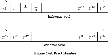 Figure 1–A Fract Number
In the 128K ROM, all fixed-point functions (that is, functions with Fixed or Fract arguments or results) handle boundary cases uniformly. Results are rounded by adding half a unit in magnitude in the last place of the stored precision and then chopping toward zero. Overflows are set to the maximum representable value with the correct sign (typically $80000000 for negative results and $7FFFFFFF for positive results). Division by zero in any of the four divide routines results in $80000000 if the numerator is negative and $7FFFFFFF otherwise; thus the special case 0/0 yields $7FFFFFFF.
Warning: Some applications may depend on spurious values returned by the
64K ROM: FixRatio and FixMul overflowed unpredictably, FixRatio
returned $80000001 when a negative number was divided by 0, and
FixRound malfunctioned with negative arguments.
Depending on which Toolbox Utilities you’re interested in using, you may need to be familiar with:
• resources, as described in the Resource Manager chapter
• the basic concepts and structures behind QuickDraw
_______________________________________________________________________________
»TOOLBOX UTILITY ROUTINES
_______________________________________________________________________________
The 128K ROM version of the Toolbox Utilities supports fifteen new fixed-point functions. Pascal typing will allow any of the operand combinations suggested here without redefinition of the function.
_______________________________________________________________________________
»Arithmetic Operations
Fixed-point numbers are described in the Macintosh Memory Management: An Introduction chapter. Note that fixed-point values can be added and subtracted as long integers.
In addition to the following routines, the HiWord and LoWord functions
(described under “Other Operations on Long Integers” below) are useful when
you’re working with fixed-point numbers.
FUNCTION FixRatio (numer,denom: INTEGER) : Fixed;
FixRatio returns the fixed-point quotient of numer and denom. Numer or denom may be any signed integer. The result is truncated. If denom is 0, FixRatio returns $7FFFFFFF if numer is positive or $80000001 if numer is negative.
FUNCTION FixMul (a,b: Fixed) : Fixed;
FixMul returns the signed fixed-point product of a and b. The result is computed MOD 65536, truncated, and signed according to the signs of a and b.
FUNCTION FixRound (x: Fixed) : INTEGER;
Given a positive fixed-point number, FixRound rounds it to the nearest integer and returns the result. If the value is halfway between two integers (.5), it’s rounded up.
Note: To round a negative fixed-point number, negate it, round,
then negate it again.
FUNCTION FracMul (x,y: Fract) : Fract;
FracMul returns x * y. Note that FracMul effects “type * Fract --> type”:
Fract * Fract --> Fract
LONGINT * Fract --> LONGINT
Fract * LONGINT --> LONGINT
Fixed * Fract --> Fixed
Fract * Fixed --> Fixed
FUNCTION FixDiv (x,y: Fixed) : Fixed;
FixDiv returns x / y. Note that FixDiv effects “type / type --> Fixed” and
“type / Fixed --> type”:
Fixed / Fixed --> Fixed
LONGINT / LONGINT --> Fixed
Fract / Fract --> Fixed
LONGINT / Fixed --> LONGINT
Fract / Fixed --> Fract
FUNCTION FracDiv (x,y: Fract) : Fract;
FracDiv returns x / y. Note that FracDiv effects “type / type --> Fract” and
“type / Fract --> type”:
Fract / Fract --> Fract
LONGINT / LONGINT --> Fract
Fixed / Fixed --> Fract
LONGINT / Fract --> LONGINT
Fixed / Fract --> Fixed
FUNCTION FracSqrt (x: Fract) : Fract;
FracSqrt returns the square root of x, with x interpreted as unsigned in the range 0 through 4–(2–30), inclusive: That is, bit 15 in Figure 1 has weight 2 rather than –2. The result, too, is unsigned in the range 0 through 2, inclusive.
FUNCTION FracCos (x: Fixed) : Fract;
FUNCTION FracSin (x: Fixed) : Fract;
FracCos and FracSin return the cosine and sine of their radian arguments, respectively. The hexadecimal value 0.C910 (which is FixATan2(1,1)) is the approximation to π/4 used for argument reduction. Thus, FracCos and FracSin are nearly periodic, but with period 2*P instead of 2*π, where P=3.1416015625 and π, of course, is 3.14159265....
FUNCTION FixATan2 (x,y: LONGINT) : Fixed;
FixATan2 returns the arctangent of y / x in radians. Note that FixATan2 effects “arctan(type / type) --> Fixed”:
arctan(LONGINT / LONGINT) --> Fixed
arctan(Fixed / Fixed) --> Fixed
arctan(Fract / Fract) --> Fixed
_______________________________________________________________________________
»Conversion Functions
FUNCTION Long2Fix (x: LONGINT) : Fixed;
FUNCTION Fix2Long (x: Fixed) : LONGINT;
FUNCTION Fix2Frac (x: Fixed) : Fract;
FUNCTION Frac2Fix (x: Fract) : Fixed;
Long2Fix, Fix2Long, Fix2Frac, and Frac2Fix convert between fixed-point types.
FUNCTION Fix2X (x: Fixed) : Extended;
FUNCTION X2Fix (x: Extended) : Fixed;
FUNCTION Frac2X (x: Fract) : Extended;
FUNCTION X2Frac (x: Extended) : Fract;
Fix2X, X2Fix, Frac2X, and X2Frac convert between Fixed and Fract and the Extended floating-point type. These functions do not set floating-point exception flags.
Examples
Examples of the use of these fixed-point functions are provided below; all numbers are decimal unless otherwise noted.
Function Result Comment
FixDiv (X2Fix(1.95), X2Fix(1.30)) $00018000 1.5 = 01.10 bin
FracDiv (X2Frac(1.95), X2Frac(1.30)) $60000000 1.5 = 01.10 bin
FracMul (X2Frac(1.50), X2Frac(1.30)) $7CCCCCCD 1.95 rounded
FracSqrt (X2Frac(1.96)) $5999999A 1.4 rounded
FracSin (X2Fix(3.1416015625)) $00000000 0
FracCos (X2Fix(3.1416015625)) $C0000000 -1
Fix2Long (X2Fix(1.75)) $00000002 2
Fix2Frac (X2Fix(1.75)) $70000000 1.75 = 01.11 bin
Frac2Fix (X2Frac(1.75)) $0001C000 1.75 = 01.11 bin
FixATan2 (X2Fix(1.00), X2Fix(1.00)) $0000C910 0.C910 hex = X2Fix (π/4)
FixDiv (X2Fix(-1.95), X2Fix(1.30)) $FFFE8000 -1.5
FracDiv (X2Frac(-1.95), X2Frac(1.30)) $A0000000 -1.5
FracMul (X2Frac(-1.50), X2Frac(1.30)) $83333333 -1.95 rounded
FracSin (X2Fix(-3.1416015625)) $00000000 0
FracCos (X2Fix(-3.1416015625)) $C0000000 -1
Fix2Long (X2Fix(-1.75)) $FFFFFFFE -2
Fix2Frac (X2Fix(-1.75)) $90000000 -1.75
Frac2Fix (X2Frac(-1.75)) $FFFE4000 -1.75
FixATan2 (X2Fix(-1.00), X2Fix(-1.00)) $FFFDA4D0 -3*X2Fix(π/4)=3*0.C910 hex
_______________________________________________________________________________
»String Manipulation
FUNCTION NewString (theString: Str255) : StringHandle;
NewString allocates the specified string as a relocatable object in the heap and returns a handle to it.
Note: NewString returns a handle to a string whose size is based on its
actual length (not necessarily 255); if you’re going to use Pascal
string functions that could change the length of the string, you may
want to call SetString or the Memory Manager procedure SetHandleSize
first to set the string to the maximum size.
PROCEDURE SetString (h: StringHandle; theString: Str255);
SetString sets the string whose handle is passed in h to the string specified by theString.
FUNCTION GetString (stringID: INTEGER) : StringHandle;
GetString returns a handle to the string having the given resource ID, reading it from the resource file if necessary. It calls the Resource Manager function GetResource('STR ',stringID). If the resource can’t be read, GetString returns NIL.
Note: Like NewString, GetString returns a handle to a string whose size is
based on its actual length.
Note: If your application uses a large number of strings, storing them in
a string list in the resource file will be more efficient. You can
access strings in a string list with GetIndString, as described below.
PROCEDURE GetIndString (VAR theString: Str255; strListID: INTEGER;
index: INTEGER); [Not in ROM]
GetIndString returns in theString a string in the string list that has the resource ID strListID. It reads the string list from the resource file if necessary, by calling the Resource Manager function GetResource('STR#',strListID). It returns the string specified by the index parameter, which can range from 1 to the number of strings in the list. If the resource can’t be read or the index is out of range, the empty string is returned.
_______________________________________________________________________________
»Byte Manipulation
FUNCTION Munger (h: Handle; offset: LONGINT; ptr1: Ptr; len1: LONGINT;
ptr2: Ptr; len2: LONGINT) : LONGINT;
Munger (which rhymes with “plunger”) lets you manipulate bytes in the string of bytes (the “destination string”) to which h is a handle. The operation starts at the specified byte offset in the destination string.
Note: Although the term “string” is used here, Munger does not assume it’s
manipulating a Pascal string; if you pass it a handle to a Pascal
string, you must take into account the length byte.
The exact nature of the operation done by Munger depends on the values you pass it in two pointer/length parameter pairs. In general, (ptr1,len1) defines a target string to be replaced by the second string (ptr2,len2). If these four parameters are all positive and nonzero, Munger looks for the target string in the destination string, starting from the given offset and ending at the end of the string; it replaces the first occurrence it finds with the replacement string and returns the offset of the first byte past where the replacement occurred. Figure 2 illustrates this; the bytes represent ASCII characters as shown.
Figure 1–A Fract Number
In the 128K ROM, all fixed-point functions (that is, functions with Fixed or Fract arguments or results) handle boundary cases uniformly. Results are rounded by adding half a unit in magnitude in the last place of the stored precision and then chopping toward zero. Overflows are set to the maximum representable value with the correct sign (typically $80000000 for negative results and $7FFFFFFF for positive results). Division by zero in any of the four divide routines results in $80000000 if the numerator is negative and $7FFFFFFF otherwise; thus the special case 0/0 yields $7FFFFFFF.
Warning: Some applications may depend on spurious values returned by the
64K ROM: FixRatio and FixMul overflowed unpredictably, FixRatio
returned $80000001 when a negative number was divided by 0, and
FixRound malfunctioned with negative arguments.
Depending on which Toolbox Utilities you’re interested in using, you may need to be familiar with:
• resources, as described in the Resource Manager chapter
• the basic concepts and structures behind QuickDraw
_______________________________________________________________________________
»TOOLBOX UTILITY ROUTINES
_______________________________________________________________________________
The 128K ROM version of the Toolbox Utilities supports fifteen new fixed-point functions. Pascal typing will allow any of the operand combinations suggested here without redefinition of the function.
_______________________________________________________________________________
»Arithmetic Operations
Fixed-point numbers are described in the Macintosh Memory Management: An Introduction chapter. Note that fixed-point values can be added and subtracted as long integers.
In addition to the following routines, the HiWord and LoWord functions
(described under “Other Operations on Long Integers” below) are useful when
you’re working with fixed-point numbers.
FUNCTION FixRatio (numer,denom: INTEGER) : Fixed;
FixRatio returns the fixed-point quotient of numer and denom. Numer or denom may be any signed integer. The result is truncated. If denom is 0, FixRatio returns $7FFFFFFF if numer is positive or $80000001 if numer is negative.
FUNCTION FixMul (a,b: Fixed) : Fixed;
FixMul returns the signed fixed-point product of a and b. The result is computed MOD 65536, truncated, and signed according to the signs of a and b.
FUNCTION FixRound (x: Fixed) : INTEGER;
Given a positive fixed-point number, FixRound rounds it to the nearest integer and returns the result. If the value is halfway between two integers (.5), it’s rounded up.
Note: To round a negative fixed-point number, negate it, round,
then negate it again.
FUNCTION FracMul (x,y: Fract) : Fract;
FracMul returns x * y. Note that FracMul effects “type * Fract --> type”:
Fract * Fract --> Fract
LONGINT * Fract --> LONGINT
Fract * LONGINT --> LONGINT
Fixed * Fract --> Fixed
Fract * Fixed --> Fixed
FUNCTION FixDiv (x,y: Fixed) : Fixed;
FixDiv returns x / y. Note that FixDiv effects “type / type --> Fixed” and
“type / Fixed --> type”:
Fixed / Fixed --> Fixed
LONGINT / LONGINT --> Fixed
Fract / Fract --> Fixed
LONGINT / Fixed --> LONGINT
Fract / Fixed --> Fract
FUNCTION FracDiv (x,y: Fract) : Fract;
FracDiv returns x / y. Note that FracDiv effects “type / type --> Fract” and
“type / Fract --> type”:
Fract / Fract --> Fract
LONGINT / LONGINT --> Fract
Fixed / Fixed --> Fract
LONGINT / Fract --> LONGINT
Fixed / Fract --> Fixed
FUNCTION FracSqrt (x: Fract) : Fract;
FracSqrt returns the square root of x, with x interpreted as unsigned in the range 0 through 4–(2–30), inclusive: That is, bit 15 in Figure 1 has weight 2 rather than –2. The result, too, is unsigned in the range 0 through 2, inclusive.
FUNCTION FracCos (x: Fixed) : Fract;
FUNCTION FracSin (x: Fixed) : Fract;
FracCos and FracSin return the cosine and sine of their radian arguments, respectively. The hexadecimal value 0.C910 (which is FixATan2(1,1)) is the approximation to π/4 used for argument reduction. Thus, FracCos and FracSin are nearly periodic, but with period 2*P instead of 2*π, where P=3.1416015625 and π, of course, is 3.14159265....
FUNCTION FixATan2 (x,y: LONGINT) : Fixed;
FixATan2 returns the arctangent of y / x in radians. Note that FixATan2 effects “arctan(type / type) --> Fixed”:
arctan(LONGINT / LONGINT) --> Fixed
arctan(Fixed / Fixed) --> Fixed
arctan(Fract / Fract) --> Fixed
_______________________________________________________________________________
»Conversion Functions
FUNCTION Long2Fix (x: LONGINT) : Fixed;
FUNCTION Fix2Long (x: Fixed) : LONGINT;
FUNCTION Fix2Frac (x: Fixed) : Fract;
FUNCTION Frac2Fix (x: Fract) : Fixed;
Long2Fix, Fix2Long, Fix2Frac, and Frac2Fix convert between fixed-point types.
FUNCTION Fix2X (x: Fixed) : Extended;
FUNCTION X2Fix (x: Extended) : Fixed;
FUNCTION Frac2X (x: Fract) : Extended;
FUNCTION X2Frac (x: Extended) : Fract;
Fix2X, X2Fix, Frac2X, and X2Frac convert between Fixed and Fract and the Extended floating-point type. These functions do not set floating-point exception flags.
Examples
Examples of the use of these fixed-point functions are provided below; all numbers are decimal unless otherwise noted.
Function Result Comment
FixDiv (X2Fix(1.95), X2Fix(1.30)) $00018000 1.5 = 01.10 bin
FracDiv (X2Frac(1.95), X2Frac(1.30)) $60000000 1.5 = 01.10 bin
FracMul (X2Frac(1.50), X2Frac(1.30)) $7CCCCCCD 1.95 rounded
FracSqrt (X2Frac(1.96)) $5999999A 1.4 rounded
FracSin (X2Fix(3.1416015625)) $00000000 0
FracCos (X2Fix(3.1416015625)) $C0000000 -1
Fix2Long (X2Fix(1.75)) $00000002 2
Fix2Frac (X2Fix(1.75)) $70000000 1.75 = 01.11 bin
Frac2Fix (X2Frac(1.75)) $0001C000 1.75 = 01.11 bin
FixATan2 (X2Fix(1.00), X2Fix(1.00)) $0000C910 0.C910 hex = X2Fix (π/4)
FixDiv (X2Fix(-1.95), X2Fix(1.30)) $FFFE8000 -1.5
FracDiv (X2Frac(-1.95), X2Frac(1.30)) $A0000000 -1.5
FracMul (X2Frac(-1.50), X2Frac(1.30)) $83333333 -1.95 rounded
FracSin (X2Fix(-3.1416015625)) $00000000 0
FracCos (X2Fix(-3.1416015625)) $C0000000 -1
Fix2Long (X2Fix(-1.75)) $FFFFFFFE -2
Fix2Frac (X2Fix(-1.75)) $90000000 -1.75
Frac2Fix (X2Frac(-1.75)) $FFFE4000 -1.75
FixATan2 (X2Fix(-1.00), X2Fix(-1.00)) $FFFDA4D0 -3*X2Fix(π/4)=3*0.C910 hex
_______________________________________________________________________________
»String Manipulation
FUNCTION NewString (theString: Str255) : StringHandle;
NewString allocates the specified string as a relocatable object in the heap and returns a handle to it.
Note: NewString returns a handle to a string whose size is based on its
actual length (not necessarily 255); if you’re going to use Pascal
string functions that could change the length of the string, you may
want to call SetString or the Memory Manager procedure SetHandleSize
first to set the string to the maximum size.
PROCEDURE SetString (h: StringHandle; theString: Str255);
SetString sets the string whose handle is passed in h to the string specified by theString.
FUNCTION GetString (stringID: INTEGER) : StringHandle;
GetString returns a handle to the string having the given resource ID, reading it from the resource file if necessary. It calls the Resource Manager function GetResource('STR ',stringID). If the resource can’t be read, GetString returns NIL.
Note: Like NewString, GetString returns a handle to a string whose size is
based on its actual length.
Note: If your application uses a large number of strings, storing them in
a string list in the resource file will be more efficient. You can
access strings in a string list with GetIndString, as described below.
PROCEDURE GetIndString (VAR theString: Str255; strListID: INTEGER;
index: INTEGER); [Not in ROM]
GetIndString returns in theString a string in the string list that has the resource ID strListID. It reads the string list from the resource file if necessary, by calling the Resource Manager function GetResource('STR#',strListID). It returns the string specified by the index parameter, which can range from 1 to the number of strings in the list. If the resource can’t be read or the index is out of range, the empty string is returned.
_______________________________________________________________________________
»Byte Manipulation
FUNCTION Munger (h: Handle; offset: LONGINT; ptr1: Ptr; len1: LONGINT;
ptr2: Ptr; len2: LONGINT) : LONGINT;
Munger (which rhymes with “plunger”) lets you manipulate bytes in the string of bytes (the “destination string”) to which h is a handle. The operation starts at the specified byte offset in the destination string.
Note: Although the term “string” is used here, Munger does not assume it’s
manipulating a Pascal string; if you pass it a handle to a Pascal
string, you must take into account the length byte.
The exact nature of the operation done by Munger depends on the values you pass it in two pointer/length parameter pairs. In general, (ptr1,len1) defines a target string to be replaced by the second string (ptr2,len2). If these four parameters are all positive and nonzero, Munger looks for the target string in the destination string, starting from the given offset and ending at the end of the string; it replaces the first occurrence it finds with the replacement string and returns the offset of the first byte past where the replacement occurred. Figure 2 illustrates this; the bytes represent ASCII characters as shown.
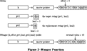 Figure 2–Munger Function
Different operations occur if either pointer is NIL or either length is 0:
• If ptr1 is NIL, the substring of length len1 starting at the given
offset is replaced by the replacement string. If len1 is negative, the
substring from the given offset to the end of the destination string is
replaced by the replacement string. In either case, Munger returns the
offset of the first byte past where the replacement occurred.
• If len1 is 0, (ptr2,len2) is simply inserted at the given offset; no
text is replaced. Munger returns the offset of the first byte past where
the insertion occurred.
• If ptr2 is NIL, Munger returns the offset at which the target string
was found. The destination string isn’t changed.
• If len2 is 0 (and ptr2 is not NIL), the target string is deleted rather
than replaced (since the replacement string is empty). Munger returns
the offset at which the deletion occurred.
If it can’t find the target string in the destination string, Munger returns a negative value.
There’s one case in which Munger performs a replacement even if it doesn’t find all of the target string. If the substring from the offset to the end of the destination string matches the beginning of the target string, the portion found is replaced with the replacement string.
Warning: Be careful not to specify an offset that’s greater than the length
of the destination string, or unpredictable results may occur.
Note: The destination string must be in a relocatable block that was
allocated by the Memory Manager. Munger accesses the string’s length
by calling the Memory Manager routines GetHandleSize and SetHandleSize.
PROCEDURE PackBits (VAR srcPtr,dstPtr: Ptr; srcBytes: INTEGER);
PackBits compresses srcBytes bytes of data starting at srcPtr and stores the compressed data at dstPtr. The value of srcBytes should not be greater than 127. Bytes are compressed when there are three or more consecutive equal bytes. After the data is compressed, srcPtr is incremented by srcBytes and dstPtr is incremented by the number of bytes that the data was compressed to. In the worst case, the compressed data can be one byte longer than the original data.
PackBits is usually used to compress QuickDraw bit images; in this case, you should call it for one row at a time. (Because of the repeating patterns in QuickDraw images, there are more likely to be consecutive equal bytes there than in other data.) Use UnpackBits (below) to expand data compressed by PackBits.
PROCEDURE UnpackBits (VAR srcPtr,dstPtr: Ptr; dstBytes: INTEGER);
Given in srcPtr a pointer to data that was compressed by PackBits, UnpackBits expands the data and stores the result at dstPtr. DstBytes is the length that the expanded data will be; it should be the value that was passed to PackBits in the srcBytes parameter. After the data is expanded, srcPtr is incremented by the number of bytes that were expanded and dstPtr is incremented by dstBytes.
_______________________________________________________________________________
»Bit Manipulation
Given a pointer and an offset, these routines can manipulate any specific bit. The pointer can point to an even or odd byte; the offset can be any positive long integer, starting at 0 for the high-order bit of the specified byte (see Figure 3).
Figure 2–Munger Function
Different operations occur if either pointer is NIL or either length is 0:
• If ptr1 is NIL, the substring of length len1 starting at the given
offset is replaced by the replacement string. If len1 is negative, the
substring from the given offset to the end of the destination string is
replaced by the replacement string. In either case, Munger returns the
offset of the first byte past where the replacement occurred.
• If len1 is 0, (ptr2,len2) is simply inserted at the given offset; no
text is replaced. Munger returns the offset of the first byte past where
the insertion occurred.
• If ptr2 is NIL, Munger returns the offset at which the target string
was found. The destination string isn’t changed.
• If len2 is 0 (and ptr2 is not NIL), the target string is deleted rather
than replaced (since the replacement string is empty). Munger returns
the offset at which the deletion occurred.
If it can’t find the target string in the destination string, Munger returns a negative value.
There’s one case in which Munger performs a replacement even if it doesn’t find all of the target string. If the substring from the offset to the end of the destination string matches the beginning of the target string, the portion found is replaced with the replacement string.
Warning: Be careful not to specify an offset that’s greater than the length
of the destination string, or unpredictable results may occur.
Note: The destination string must be in a relocatable block that was
allocated by the Memory Manager. Munger accesses the string’s length
by calling the Memory Manager routines GetHandleSize and SetHandleSize.
PROCEDURE PackBits (VAR srcPtr,dstPtr: Ptr; srcBytes: INTEGER);
PackBits compresses srcBytes bytes of data starting at srcPtr and stores the compressed data at dstPtr. The value of srcBytes should not be greater than 127. Bytes are compressed when there are three or more consecutive equal bytes. After the data is compressed, srcPtr is incremented by srcBytes and dstPtr is incremented by the number of bytes that the data was compressed to. In the worst case, the compressed data can be one byte longer than the original data.
PackBits is usually used to compress QuickDraw bit images; in this case, you should call it for one row at a time. (Because of the repeating patterns in QuickDraw images, there are more likely to be consecutive equal bytes there than in other data.) Use UnpackBits (below) to expand data compressed by PackBits.
PROCEDURE UnpackBits (VAR srcPtr,dstPtr: Ptr; dstBytes: INTEGER);
Given in srcPtr a pointer to data that was compressed by PackBits, UnpackBits expands the data and stores the result at dstPtr. DstBytes is the length that the expanded data will be; it should be the value that was passed to PackBits in the srcBytes parameter. After the data is expanded, srcPtr is incremented by the number of bytes that were expanded and dstPtr is incremented by dstBytes.
_______________________________________________________________________________
»Bit Manipulation
Given a pointer and an offset, these routines can manipulate any specific bit. The pointer can point to an even or odd byte; the offset can be any positive long integer, starting at 0 for the high-order bit of the specified byte (see Figure 3).
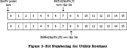 Figure 3–Bit Numbering for Utility Routines
Note: This bit numbering is the opposite of the MC68000 bit numbering to
allow for greater generality. For example, you can directly access
bit 1000 of a bit image given a pointer to the beginning of the bit
image.
FUNCTION BitTst (bytePtr: Ptr; bitNum: LONGINT) : BOOLEAN;
BitTst tests whether a given bit is set and returns TRUE if so or FALSE if not. The bit is specified by bitNum, an offset from the high-order bit of the byte pointed to by bytePtr.
PROCEDURE BitSet (bytePtr: Ptr; bitNum: LONGINT);
BitSet sets the bit specified by bitNum, an offset from the high-order bit of the byte pointed to by bytePtr.
PROCEDURE BitClr (bytePtr: Ptr; bitNum: LONGINT);
BitSet clears the bit specified by bitNum, an offset from the high-order bit of the byte pointed to by bytePtr.
_______________________________________________________________________________
»Logical Operations
FUNCTION BitAnd (value1,value2: LONGINT) : LONGINT;
BitAnd returns the result of the AND logical operation on the bits comprising the given long integers (value1 AND value2).
FUNCTION BitOr (value1,value2: LONGINT) : LONGINT;
BitOr returns the result of the OR logical operation on the bits comprising given long integers (value1 OR value2).
FUNCTION BitXor (value1,value2: LONGINT) : LONGINT;
BitXor returns the result of the XOR logical operation on the bits comprising the given long integers (value1 XOR value2).
FUNCTION BitNot (value: LONGINT) : LONGINT;
BitNot returns the result of the NOT logical operation on the bits comprising the given long integer (NOT value).
FUNCTION BitShift (value: LONGINT; count: INTEGER) : LONGINT;
BitShift logically shifts the bits of the given long integer. The count parameter specifies the direction and extent of the shift, and is taken MOD 32. If count is positive, BitShift shifts that many positions to the left; if count is negative, it shifts to the right. Zeroes are shifted into empty positions at either end.
_______________________________________________________________________________
»Other Operations on Long Integers
FUNCTION HiWord (x: LONGINT) : INTEGER;
HiWord returns the high-order word of the given long integer. One use of this function is to extract the integer part of a fixed-point number.
FUNCTION LoWord (x: LONGINT) : INTEGER;
LoWord returns the low-order word of the given long integer. One use of this function is to extract the fractional part of a fixed-point number.
Note: If you’re dealing with a long integer that contains two separate
integer values, you can define a variant record instead of using
HiWord and LoWord. For example, for fixed-point numbers, you could
define the following type:
TYPE FixedAndInt = RECORD CASE INTEGER OF
1: (fixedView: Fixed);
2: (intView: RECORD
whole: INTEGER;
part: INTEGER
END;
END;
If you declare x to be of type FixedAndInt, you can access it as a fixed-point value with x.fixedView, or access the integer part with x.intView.whole and the fractional part with x.intView.part.
PROCEDURE LongMul (a,b: LONGINT; VAR dest: Int64Bit);
LongMul multiplies the given long integers and returns the signed result in dest, which has the following data type:
TYPE Int64Bit = RECORD
hiLong: LONGINT;
loLong: LONGINT
END;
_______________________________________________________________________________
»Graphics Utilities
PROCEDURE ScreenRes (VAR scrnHRes,scrnVRes: INTEGER); [Not in ROM]
ScreenRes returns the resolution of the screen of the Macintosh being used. ScrnHRes and scrnVRes are the number of pixels per inch horizontally and vertically, respectively.
Assembly-language note: The number of pixels per inch horizontally is stored
in the global variable ScrHRes, and the number of
pixels per inch vertically is stored in ScrVRes.
FUNCTION GetIcon (iconID: INTEGER) : Handle;
GetIcon returns a handle to the icon having the given resource ID, reading it from the resource file if necessary. It calls the Resource Manager function GetResource('ICON',iconID). If the resource can’t be read, GetIcon returns NIL.
PROCEDURE PlotIcon (theRect: Rect; theIcon: Handle);
PlotIcon draws the icon whose handle is theIcon in the rectangle theRect, which is in the local coordinates of the current grafPort. It calls the QuickDraw procedure CopyBits and uses the srcCopy transfer mode.
FUNCTION GetPattern (patID: INTEGER) : PatHandle;
GetPattern returns a handle to the pattern having the given resource ID, reading it from the resource file if necessary. It calls the Resource Manager function GetResource('PAT ',patID). If the resource can’t be read, GetPattern returns NIL. The PatHandle data type is defined in the Toolbox Utilities as follows:
TYPE PatPtr = ^Pattern;
PatHandle = ^PatPtr;
PROCEDURE GetIndPattern (VAR thePattern: Pattern; patListID: INTEGER;
index: INTEGER); [Not in ROM]
GetIndPattern returns in thePattern a pattern in the pattern list that has the resource ID patListID. It reads the pattern list from the resource file if necessary, by calling the Resource Manager function GetResource('PAT#',patListID). It returns the pattern specified by the index parameter, which can range from 1 to the number of patterns in the pattern list.
There’s a pattern list in the system resource file that contains the standard Macintosh patterns used by MacPaint (see Figure 4). Its resource ID is:
CONST sysPatListID = 0;
Figure 3–Bit Numbering for Utility Routines
Note: This bit numbering is the opposite of the MC68000 bit numbering to
allow for greater generality. For example, you can directly access
bit 1000 of a bit image given a pointer to the beginning of the bit
image.
FUNCTION BitTst (bytePtr: Ptr; bitNum: LONGINT) : BOOLEAN;
BitTst tests whether a given bit is set and returns TRUE if so or FALSE if not. The bit is specified by bitNum, an offset from the high-order bit of the byte pointed to by bytePtr.
PROCEDURE BitSet (bytePtr: Ptr; bitNum: LONGINT);
BitSet sets the bit specified by bitNum, an offset from the high-order bit of the byte pointed to by bytePtr.
PROCEDURE BitClr (bytePtr: Ptr; bitNum: LONGINT);
BitSet clears the bit specified by bitNum, an offset from the high-order bit of the byte pointed to by bytePtr.
_______________________________________________________________________________
»Logical Operations
FUNCTION BitAnd (value1,value2: LONGINT) : LONGINT;
BitAnd returns the result of the AND logical operation on the bits comprising the given long integers (value1 AND value2).
FUNCTION BitOr (value1,value2: LONGINT) : LONGINT;
BitOr returns the result of the OR logical operation on the bits comprising given long integers (value1 OR value2).
FUNCTION BitXor (value1,value2: LONGINT) : LONGINT;
BitXor returns the result of the XOR logical operation on the bits comprising the given long integers (value1 XOR value2).
FUNCTION BitNot (value: LONGINT) : LONGINT;
BitNot returns the result of the NOT logical operation on the bits comprising the given long integer (NOT value).
FUNCTION BitShift (value: LONGINT; count: INTEGER) : LONGINT;
BitShift logically shifts the bits of the given long integer. The count parameter specifies the direction and extent of the shift, and is taken MOD 32. If count is positive, BitShift shifts that many positions to the left; if count is negative, it shifts to the right. Zeroes are shifted into empty positions at either end.
_______________________________________________________________________________
»Other Operations on Long Integers
FUNCTION HiWord (x: LONGINT) : INTEGER;
HiWord returns the high-order word of the given long integer. One use of this function is to extract the integer part of a fixed-point number.
FUNCTION LoWord (x: LONGINT) : INTEGER;
LoWord returns the low-order word of the given long integer. One use of this function is to extract the fractional part of a fixed-point number.
Note: If you’re dealing with a long integer that contains two separate
integer values, you can define a variant record instead of using
HiWord and LoWord. For example, for fixed-point numbers, you could
define the following type:
TYPE FixedAndInt = RECORD CASE INTEGER OF
1: (fixedView: Fixed);
2: (intView: RECORD
whole: INTEGER;
part: INTEGER
END;
END;
If you declare x to be of type FixedAndInt, you can access it as a fixed-point value with x.fixedView, or access the integer part with x.intView.whole and the fractional part with x.intView.part.
PROCEDURE LongMul (a,b: LONGINT; VAR dest: Int64Bit);
LongMul multiplies the given long integers and returns the signed result in dest, which has the following data type:
TYPE Int64Bit = RECORD
hiLong: LONGINT;
loLong: LONGINT
END;
_______________________________________________________________________________
»Graphics Utilities
PROCEDURE ScreenRes (VAR scrnHRes,scrnVRes: INTEGER); [Not in ROM]
ScreenRes returns the resolution of the screen of the Macintosh being used. ScrnHRes and scrnVRes are the number of pixels per inch horizontally and vertically, respectively.
Assembly-language note: The number of pixels per inch horizontally is stored
in the global variable ScrHRes, and the number of
pixels per inch vertically is stored in ScrVRes.
FUNCTION GetIcon (iconID: INTEGER) : Handle;
GetIcon returns a handle to the icon having the given resource ID, reading it from the resource file if necessary. It calls the Resource Manager function GetResource('ICON',iconID). If the resource can’t be read, GetIcon returns NIL.
PROCEDURE PlotIcon (theRect: Rect; theIcon: Handle);
PlotIcon draws the icon whose handle is theIcon in the rectangle theRect, which is in the local coordinates of the current grafPort. It calls the QuickDraw procedure CopyBits and uses the srcCopy transfer mode.
FUNCTION GetPattern (patID: INTEGER) : PatHandle;
GetPattern returns a handle to the pattern having the given resource ID, reading it from the resource file if necessary. It calls the Resource Manager function GetResource('PAT ',patID). If the resource can’t be read, GetPattern returns NIL. The PatHandle data type is defined in the Toolbox Utilities as follows:
TYPE PatPtr = ^Pattern;
PatHandle = ^PatPtr;
PROCEDURE GetIndPattern (VAR thePattern: Pattern; patListID: INTEGER;
index: INTEGER); [Not in ROM]
GetIndPattern returns in thePattern a pattern in the pattern list that has the resource ID patListID. It reads the pattern list from the resource file if necessary, by calling the Resource Manager function GetResource('PAT#',patListID). It returns the pattern specified by the index parameter, which can range from 1 to the number of patterns in the pattern list.
There’s a pattern list in the system resource file that contains the standard Macintosh patterns used by MacPaint (see Figure 4). Its resource ID is:
CONST sysPatListID = 0;
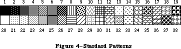 Figure 4–Standard Patterns
FUNCTION GetCursor (cursorID: INTEGER) : CursHandle;
GetCursor returns a handle to the cursor having the given resource ID, reading it from the resource file if necessary. It calls the Resource Manager function GetResource('CURS',cursorID). If the resource can’t be read, GetCursor returns NIL.
The CursHandle data type is defined in the Toolbox Utilities as follows:
TYPE CursPtr = ^Cursor;
CursHandle = ^CursPtr;
The standard cursors shown in Figure 5 are defined in the system resource file. Their resource IDs are:
CONST iBeamCursor = 1; {to select text}
crossCursor = 2; {to draw graphics}
plusCursor = 3; {to select cells in structured documents}
watchCursor = 4; {to indicate a long wait}
Figure 4–Standard Patterns
FUNCTION GetCursor (cursorID: INTEGER) : CursHandle;
GetCursor returns a handle to the cursor having the given resource ID, reading it from the resource file if necessary. It calls the Resource Manager function GetResource('CURS',cursorID). If the resource can’t be read, GetCursor returns NIL.
The CursHandle data type is defined in the Toolbox Utilities as follows:
TYPE CursPtr = ^Cursor;
CursHandle = ^CursPtr;
The standard cursors shown in Figure 5 are defined in the system resource file. Their resource IDs are:
CONST iBeamCursor = 1; {to select text}
crossCursor = 2; {to draw graphics}
plusCursor = 3; {to select cells in structured documents}
watchCursor = 4; {to indicate a long wait}
 Figure 5–Standard Cursors
Note: You can set the cursor with the QuickDraw procedure SetCursor. The
arrow cursor is defined in QuickDraw as a global variable named arrow.
PROCEDURE ShieldCursor (shieldRect: Rect; offsetPt: Point);
If the cursor and the given rectangle intersect, ShieldCursor hides the cursor. If they don’t intersect, the cursor remains visible while the mouse isn’t moving, but is hidden when the mouse moves.
Like the QuickDraw procedure HideCursor, ShieldCursor decrements the cursor level, and should be balanced by a call to ShowCursor.
The rectangle may be given in global or local coordinates:
• If they’re global coordinates, pass (0,0) in offsetPt. If they’re a
grafPort’s local coordinates, pass the top left corner of the grafPort’s
boundary rectangle in offsetPt. (Like the QuickDraw procedure
LocalToGlobal, ShieldCursor will offset the coordinates of the rectangle
by the coordinates of this point.)
FUNCTION GetPicture (picID: INTEGER) : PicHandle;
GetPicture returns a handle to the picture having the given resource ID, reading it from the resource file if necessary. It calls the Resource Manager function GetResource('PICT',picID). If the resource can’t be read, GetPicture returns NIL. The PicHandle data type is defined in QuickDraw.
_______________________________________________________________________________
»Miscellaneous Utilities
FUNCTION DeltaPoint (ptA,ptB: Point) : LONGINT;
DeltaPoint subtracts the coordinates of ptB from the coordinates of ptA. The high-order word of the result is the difference of the vertical coordinates and the low-order word is the difference of the horizontal coordinates.
Note: The QuickDraw procedure SubPt also subtracts the coordinates of one
point from another, but returns the result in a VAR parameter of type
Point.
FUNCTION SlopeFromAngle (angle: INTEGER) : Fixed;
Given an angle, SlopeFromAngle returns the slope dh/dv of the line forming that angle with the y-axis (dh/dv is the horizontal change divided by the vertical change between any two points on the line). Figure 6 illustrates SlopeFromAngle (and AngleFromSlope, described below, which does the reverse). The angle is treated MOD 180, and is in degrees measured from 12 o’clock; positive degrees are measured clockwise, negative degrees are measured counterclockwise (for example, 90 degrees is at 3 o’clock and –90 degrees is at 9 o’clock). Positive y is down; positive x is to the right.
Figure 5–Standard Cursors
Note: You can set the cursor with the QuickDraw procedure SetCursor. The
arrow cursor is defined in QuickDraw as a global variable named arrow.
PROCEDURE ShieldCursor (shieldRect: Rect; offsetPt: Point);
If the cursor and the given rectangle intersect, ShieldCursor hides the cursor. If they don’t intersect, the cursor remains visible while the mouse isn’t moving, but is hidden when the mouse moves.
Like the QuickDraw procedure HideCursor, ShieldCursor decrements the cursor level, and should be balanced by a call to ShowCursor.
The rectangle may be given in global or local coordinates:
• If they’re global coordinates, pass (0,0) in offsetPt. If they’re a
grafPort’s local coordinates, pass the top left corner of the grafPort’s
boundary rectangle in offsetPt. (Like the QuickDraw procedure
LocalToGlobal, ShieldCursor will offset the coordinates of the rectangle
by the coordinates of this point.)
FUNCTION GetPicture (picID: INTEGER) : PicHandle;
GetPicture returns a handle to the picture having the given resource ID, reading it from the resource file if necessary. It calls the Resource Manager function GetResource('PICT',picID). If the resource can’t be read, GetPicture returns NIL. The PicHandle data type is defined in QuickDraw.
_______________________________________________________________________________
»Miscellaneous Utilities
FUNCTION DeltaPoint (ptA,ptB: Point) : LONGINT;
DeltaPoint subtracts the coordinates of ptB from the coordinates of ptA. The high-order word of the result is the difference of the vertical coordinates and the low-order word is the difference of the horizontal coordinates.
Note: The QuickDraw procedure SubPt also subtracts the coordinates of one
point from another, but returns the result in a VAR parameter of type
Point.
FUNCTION SlopeFromAngle (angle: INTEGER) : Fixed;
Given an angle, SlopeFromAngle returns the slope dh/dv of the line forming that angle with the y-axis (dh/dv is the horizontal change divided by the vertical change between any two points on the line). Figure 6 illustrates SlopeFromAngle (and AngleFromSlope, described below, which does the reverse). The angle is treated MOD 180, and is in degrees measured from 12 o’clock; positive degrees are measured clockwise, negative degrees are measured counterclockwise (for example, 90 degrees is at 3 o’clock and –90 degrees is at 9 o’clock). Positive y is down; positive x is to the right.
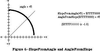 Figure 6–SlopeFromAngle and AngleFromSlope
FUNCTION AngleFromSlope (slope: Fixed) : INTEGER;
Given the slope dh/dv of a line (see SlopeFromAngle above), AngleFromSlope returns the angle formed by that line and the y-axis. The angle returned is between 1 and 180 (inclusive), in degrees measured clockwise from 12 o’clock.
AngleFromSlope is meant for use when speed is much more important than accuracy—its integer result is guaranteed to be within one degree of the correct answer, but not necessarily within half a degree. However, the equation
AngleFromSlope(SlopeFromAngle(x)) = x
is true for all x except 0 (although its reverse is not).
Note: SlopeFromAngle(0) is 0, and AngleFromSlope(0) is 180.
_______________________________________________________________________________
»FORMATS OF MISCELLANEOUS RESOURCES
_______________________________________________________________________________
The following table shows the exact format of various resources. For more information about the contents of the graphics-related resources, see the QuickDraw chapter.
Resource Resource type Number of bytes Contents
Icon 'ICON' 128 bytes The icon
Icon list 'ICN#' n * 128 bytes n icons
Pattern 'PAT ' 8 bytes The pattern
Pattern list 'PAT#' 2 bytes Number of patterns
n * 8 bytes n patterns
Cursor 'CURS' 32 bytes The data
32 bytes The mask
4 bytes The hotSpot
Picture 'PICT' 2 bytes Picture length (m+10)
8 bytes Picture frame
m bytes Picture definition data
String 'STR ' m bytes The string (1-byte length
followed by the characters)
String list 'STR#' 2 bytes Number of strings
m bytes The strings
Note: Unlike a pattern list or a string list, an icon list doesn’t start
with the number of items in the list.
_______________________________________________________________________________
»SUMMARY OF THE TOOLBOX UTILITIES
_______________________________________________________________________________
Constants
CONST
{ Resource ID of standard pattern list }
sysPatListID = 0;
{ Resource IDs of standard cursors }
iBeamCursor = 1; {to select text}
crossCursor = 2; {to draw graphics}
plusCursor = 3; {to select cells in structured documents}
watchCursor = 4; {to indicate a long wait}
_______________________________________________________________________________
Data Types
TYPE
Int64Bit = RECORD
hiLong: LONGINT;
loLong: LONGINT
END;
CursPtr = ^Cursor;
CursHandle = ^CursPtr;
PatPtr = ^Pattern;
PatHandle = ^PatPtr;
_______________________________________________________________________________
Routines
Arithmetic Operations
FUNCTION FixRatio (numer,denom: INTEGER) : Fixed;
FUNCTION FixMul (a,b: Fixed) : Fixed;
FUNCTION FixRound (x: Fixed) : INTEGER;
FUNCTION FracMul (x,y : Fract) : Fract;
FUNCTION FixDiv (x,y: Fixed) : Fixed;
FUNCTION FracDiv (x,y: Fract) : Fract;
FUNCTION FracSqrt (x: Fract) : Fract;
FUNCTION FracCos (x: Fixed) : Fract;
FUNCTION FracSin (x: Fixed) : Fract;
FUNCTION FixATan2 (x,y: LONGINT) : Fixed;
Conversion Functions
FUNCTION Long2Fix (x: LONGINT) : Fixed;
FUNCTION Fix2Long (x: Fixed) : LONGINT;
FUNCTION Fix2Frac (x: Fixed) : Fract;
FUNCTION Frac2Fix (x: Fract) : Fixed;
FUNCTION Fix2X (x: Fixed) : Extended;
FUNCTION X2Fix (x: Extended) : Fixed;
FUNCTION Frac2X (x: Fract) : Extended;
FUNCTION X2Frac (x: Extended) : Fract;
String Manipulation
FUNCTION NewString (theString: Str255) : StringHandle;
PROCEDURE SetString (h: StringHandle; theString: Str255);
FUNCTION GetString (stringID: INTEGER) : StringHandle;
PROCEDURE GetIndString (VAR theString: Str255; strListID: INTEGER;
index: INTEGER); [Not in ROM]
Byte Manipulation
FUNCTION Munger (h: Handle; offset: LONGINT; ptr1: Ptr; len1: LONGINT;
ptr2: Ptr; len2: LONGINT) : LONGINT;
PROCEDURE PackBits (VAR srcPtr,dstPtr: Ptr; srcBytes: INTEGER);
PROCEDURE UnpackBits (VAR srcPtr,dstPtr: Ptr; dstBytes: INTEGER);
Bit Manipulation
FUNCTION BitTst (bytePtr: Ptr; bitNum: LONGINT) : BOOLEAN;
PROCEDURE BitSet (bytePtr: Ptr; bitNum: LONGINT);
PROCEDURE BitClr (bytePtr: Ptr; bitNum: LONGINT);
Logical Operations
FUNCTION BitAnd (value1,value2: LONGINT) : LONGINT;
FUNCTION BitOr (value1,value2: LONGINT) : LONGINT;
FUNCTION BitXor (value1,value2: LONGINT) : LONGINT;
FUNCTION BitNot (value: LONGINT) : LONGINT;
FUNCTION BitShift (value: LONGINT; count: INTEGER) : LONGINT;
Other Operations on Long Integers
FUNCTION HiWord (x: LONGINT) : INTEGER;
FUNCTION LoWord (x: LONGINT) : INTEGER;
PROCEDURE LongMul (a,b: LONGINT; VAR dest: Int64Bit);
Graphics Utilities
PROCEDURE ScreenRes (VAR scrnHRes,scrnVRes: INTEGER); [Not in ROM]
FUNCTION GetIcon (iconID: INTEGER) : Handle;
PROCEDURE PlotIcon (theRect: Rect; theIcon: Handle);
FUNCTION GetPattern (patID: INTEGER) : PatHandle;
PROCEDURE GetIndPattern (VAR thePattern: Pattern; patListID: INTEGER;
index: INTEGER); [Not in ROM]
FUNCTION GetCursor (cursorID: INTEGER) : CursHandle;
PROCEDURE ShieldCursor (shieldRect: Rect; offsetPt: Point);
FUNCTION GetPicture (picID: INTEGER) : PicHandle;
Miscellaneous Utilities
FUNCTION DeltaPoint (ptA,ptB: Point) : LONGINT;
FUNCTION SlopeFromAngle (angle: INTEGER) : Fixed;
FUNCTION AngleFromSlope (slope: Fixed) : INTEGER;
_______________________________________________________________________________
Assembly-Language Information
Constants
; Resource ID of standard pattern list
sysPatListID .EQU 0
; Resource IDs of standard cursors
iBeamCursor .EQU 1 ;to select text
crossCursor .EQU 2 ;to draw graphics
plusCursor .EQU 3 ;to select cells in structured documents
watchCursor .EQU 4 ;to indicate a long wait
Variables
ScrVRes Pixels per inch vertically (word)
ScrHRes Pixels per inch horizontally (word)
Further Reference:
_______________________________________________________________________________
Resource Manager
QuickDraw
Technical Note #55, Drawing Icons
Technical Note #86, MacPaint Document Format
Technical Note #171, _PackBits Data Format
Technical Note #252, Plotting Small Icons
Figure 6–SlopeFromAngle and AngleFromSlope
FUNCTION AngleFromSlope (slope: Fixed) : INTEGER;
Given the slope dh/dv of a line (see SlopeFromAngle above), AngleFromSlope returns the angle formed by that line and the y-axis. The angle returned is between 1 and 180 (inclusive), in degrees measured clockwise from 12 o’clock.
AngleFromSlope is meant for use when speed is much more important than accuracy—its integer result is guaranteed to be within one degree of the correct answer, but not necessarily within half a degree. However, the equation
AngleFromSlope(SlopeFromAngle(x)) = x
is true for all x except 0 (although its reverse is not).
Note: SlopeFromAngle(0) is 0, and AngleFromSlope(0) is 180.
_______________________________________________________________________________
»FORMATS OF MISCELLANEOUS RESOURCES
_______________________________________________________________________________
The following table shows the exact format of various resources. For more information about the contents of the graphics-related resources, see the QuickDraw chapter.
Resource Resource type Number of bytes Contents
Icon 'ICON' 128 bytes The icon
Icon list 'ICN#' n * 128 bytes n icons
Pattern 'PAT ' 8 bytes The pattern
Pattern list 'PAT#' 2 bytes Number of patterns
n * 8 bytes n patterns
Cursor 'CURS' 32 bytes The data
32 bytes The mask
4 bytes The hotSpot
Picture 'PICT' 2 bytes Picture length (m+10)
8 bytes Picture frame
m bytes Picture definition data
String 'STR ' m bytes The string (1-byte length
followed by the characters)
String list 'STR#' 2 bytes Number of strings
m bytes The strings
Note: Unlike a pattern list or a string list, an icon list doesn’t start
with the number of items in the list.
_______________________________________________________________________________
»SUMMARY OF THE TOOLBOX UTILITIES
_______________________________________________________________________________
Constants
CONST
{ Resource ID of standard pattern list }
sysPatListID = 0;
{ Resource IDs of standard cursors }
iBeamCursor = 1; {to select text}
crossCursor = 2; {to draw graphics}
plusCursor = 3; {to select cells in structured documents}
watchCursor = 4; {to indicate a long wait}
_______________________________________________________________________________
Data Types
TYPE
Int64Bit = RECORD
hiLong: LONGINT;
loLong: LONGINT
END;
CursPtr = ^Cursor;
CursHandle = ^CursPtr;
PatPtr = ^Pattern;
PatHandle = ^PatPtr;
_______________________________________________________________________________
Routines
Arithmetic Operations
FUNCTION FixRatio (numer,denom: INTEGER) : Fixed;
FUNCTION FixMul (a,b: Fixed) : Fixed;
FUNCTION FixRound (x: Fixed) : INTEGER;
FUNCTION FracMul (x,y : Fract) : Fract;
FUNCTION FixDiv (x,y: Fixed) : Fixed;
FUNCTION FracDiv (x,y: Fract) : Fract;
FUNCTION FracSqrt (x: Fract) : Fract;
FUNCTION FracCos (x: Fixed) : Fract;
FUNCTION FracSin (x: Fixed) : Fract;
FUNCTION FixATan2 (x,y: LONGINT) : Fixed;
Conversion Functions
FUNCTION Long2Fix (x: LONGINT) : Fixed;
FUNCTION Fix2Long (x: Fixed) : LONGINT;
FUNCTION Fix2Frac (x: Fixed) : Fract;
FUNCTION Frac2Fix (x: Fract) : Fixed;
FUNCTION Fix2X (x: Fixed) : Extended;
FUNCTION X2Fix (x: Extended) : Fixed;
FUNCTION Frac2X (x: Fract) : Extended;
FUNCTION X2Frac (x: Extended) : Fract;
String Manipulation
FUNCTION NewString (theString: Str255) : StringHandle;
PROCEDURE SetString (h: StringHandle; theString: Str255);
FUNCTION GetString (stringID: INTEGER) : StringHandle;
PROCEDURE GetIndString (VAR theString: Str255; strListID: INTEGER;
index: INTEGER); [Not in ROM]
Byte Manipulation
FUNCTION Munger (h: Handle; offset: LONGINT; ptr1: Ptr; len1: LONGINT;
ptr2: Ptr; len2: LONGINT) : LONGINT;
PROCEDURE PackBits (VAR srcPtr,dstPtr: Ptr; srcBytes: INTEGER);
PROCEDURE UnpackBits (VAR srcPtr,dstPtr: Ptr; dstBytes: INTEGER);
Bit Manipulation
FUNCTION BitTst (bytePtr: Ptr; bitNum: LONGINT) : BOOLEAN;
PROCEDURE BitSet (bytePtr: Ptr; bitNum: LONGINT);
PROCEDURE BitClr (bytePtr: Ptr; bitNum: LONGINT);
Logical Operations
FUNCTION BitAnd (value1,value2: LONGINT) : LONGINT;
FUNCTION BitOr (value1,value2: LONGINT) : LONGINT;
FUNCTION BitXor (value1,value2: LONGINT) : LONGINT;
FUNCTION BitNot (value: LONGINT) : LONGINT;
FUNCTION BitShift (value: LONGINT; count: INTEGER) : LONGINT;
Other Operations on Long Integers
FUNCTION HiWord (x: LONGINT) : INTEGER;
FUNCTION LoWord (x: LONGINT) : INTEGER;
PROCEDURE LongMul (a,b: LONGINT; VAR dest: Int64Bit);
Graphics Utilities
PROCEDURE ScreenRes (VAR scrnHRes,scrnVRes: INTEGER); [Not in ROM]
FUNCTION GetIcon (iconID: INTEGER) : Handle;
PROCEDURE PlotIcon (theRect: Rect; theIcon: Handle);
FUNCTION GetPattern (patID: INTEGER) : PatHandle;
PROCEDURE GetIndPattern (VAR thePattern: Pattern; patListID: INTEGER;
index: INTEGER); [Not in ROM]
FUNCTION GetCursor (cursorID: INTEGER) : CursHandle;
PROCEDURE ShieldCursor (shieldRect: Rect; offsetPt: Point);
FUNCTION GetPicture (picID: INTEGER) : PicHandle;
Miscellaneous Utilities
FUNCTION DeltaPoint (ptA,ptB: Point) : LONGINT;
FUNCTION SlopeFromAngle (angle: INTEGER) : Fixed;
FUNCTION AngleFromSlope (slope: Fixed) : INTEGER;
_______________________________________________________________________________
Assembly-Language Information
Constants
; Resource ID of standard pattern list
sysPatListID .EQU 0
; Resource IDs of standard cursors
iBeamCursor .EQU 1 ;to select text
crossCursor .EQU 2 ;to draw graphics
plusCursor .EQU 3 ;to select cells in structured documents
watchCursor .EQU 4 ;to indicate a long wait
Variables
ScrVRes Pixels per inch vertically (word)
ScrHRes Pixels per inch horizontally (word)
Further Reference:
_______________________________________________________________________________
Resource Manager
QuickDraw
Technical Note #55, Drawing Icons
Technical Note #86, MacPaint Document Format
Technical Note #171, _PackBits Data Format
Technical Note #252, Plotting Small Icons
Appendix A - Result Codes
_______________________________________________________________________________
APPENDIX A: RESULT CODES
_______________________________________________________________________________
This appendix lists all the result codes returned by the Macintosh system software. They’re ordered by value, for convenience when debugging; the names you should actually use in your program are also listed.
The result codes are grouped roughly according to the lowest level at which the error may occur. This doesn’t mean that only routines at that level may cause those errors; higher-level software may yield the same result codes. For example, an Operating System Utility routine that calls the Memory Manager may return one of the Memory Manager result codes. Where a different or more specific meaning is appropriate in a different context, that meaning is also listed.
_______________________________________________________________________________
Value Name Meaning
_______________________________________________________________________________
0 noErr No error
Operating System Event Manager Error
1 evtNotEnb Event type not designated in system event mask
SCSI Manager Errors
2 scCommErr Communications error (operations timeout)
3 scArbNBErr Arbitration failed during SCSIGet; bus busy
4 scBadparmsErr Bad parameter or TIB opcode
5 scPhaseErr SCSI bus not in correct phase for attempted
operation
6 scCompareErr SCSI Manager busy with another operation when
SCSIGet was called
7 scMgrBusyErr SCSI Manager busy with another operation when
SCSIGet was called
8 scSequenceErr Attempted operation is out of sequence; e.g.,
calling SCSISelect before doing SCSIGet
9 scBusTOErr Bus timeout before data ready on SCSIRBlind
and SCSIWBlind
10 scComplPhaseErr SCSIComplete failed; bus not in Status phase
System Error Handler Errors
31 dsNotThe1 Not the requested disk
33 negZcbFreeErr ZcbFree is negative
84 menuPrgErr Happens when a menu is purged
Printing Manager Errors
128 iPrAbort Application or user requested abort
–1 iPrSavPFil Saving spool file
Queuing Errors
–1 qErr Entry not in queue
–2 vTypErr QType field of entry in vertical retrace queue
isn’t vType (in Pascal, ORD(vType))
Device Manager Errors
–17 controlErr Driver can’t respond to this Control call
Unimplemented control instruction (Printing Manager)
–18 statusErr Driver can’t respond to this Status call
–19 readErr Driver can’t respond to Read calls
–20 writErr Driver can’t respond to Write calls
–21 badUnitErr Driver reference number doesn’t match unit table
–22 unitEmptyErr Driver reference number specifies NIL handle
in unit table
–23 openErr Requested read/write permission doesn’t match
driver’s open permission Attempt to open RAM
Serial Driver failed
–25 dRemovErr Attempt to remove an open driver
–26 dInstErr Couldn’t find driver in resource file
–27 abortErr I/O request aborted by KillIO
iIOAbort I/O abort error (Printing Manager)
–28 notOpenErr Driver isn’t open
File Manager Errors
–33 dirFulErr File directory full
–34 dskFulErr All allocation blocks on the volume are full
–35 nsvErr Specified volume doesn’t exist
–36 ioErr I/O error
–37 bdNamErr Bad file name or volume name (perhaps zero-length)
–38 fnOpnErr File not open
–39 eofErr Logical end-of-file reached during read operation
–40 posErr Attempt to position before start of file
–42 tmfoErr Too many files open
–43 fnfErr File not found
–44 wPrErr Volume is locked by a hardware setting
–45 fLckdErr File is locked
–46 vLckdErr Volume is locked by a software flag
–47 fBsyErr File is busy; one or more files are open
–48 dupFNErr File with specified name and version number
already exists
–49 opWrErr The read/write permission of only one access
path to a file can allow writing
–50 paramErr Error in parameter list Parameters don’t specify an
existing volume, and there’s no default volume
(File Manager) Bad positioning information (Disk
Driver) Bad drive number (Disk Initialization
Package)
–51 rfNumErr Path reference number specifies nonexistent
access path
–52 gfpErr Error during GetFPos
–53 volOffLinErr Volume not on-line
–54 permErr Attempt to open locked file for writing
–55 volOnLinErr Specified volume is already mounted and on-line
–56 nsDrvErr No such drive; specified drive number doesn’t match
any number in the drive queue
–57 noMacDskErr Not a Macintosh disk; volume lacks
Macintosh-format directory
–58 extFSErr External file system; file-system identifier
is nonzero, or path reference number is greater
than 1024
–59 fsRnErr Problem during rename
–60 badMDBErr Bad master directory block;
must reinitialize volume
–61 wrPermErr Read/write permission doesn’t allow writing
Low-Level Disk Errors
–64 noDriveErr Drive isn’t connected
–65 offLinErr No disk in drive
–66 noNybErr Disk is probably blank
–67 noAdrMkErr Can’t find an address mark
–68 dataVerErr Read-verify failed
–69 badCksmErr Bad address mark
–70 badBtSlpErr Bad address mark
–71 noDtaMkErr Can’t find a data mark
–72 badDCksum Bad data mark
–73 badDBtSlp Bad data mark
–74 wrUnderrun Write underrun occurred
–75 cantStepErr Drive error
–76 tk0BadErr Can’t find track 0
–77 initIWMErr Can’t initialize disk controller chip
–78 twoSideErr Tried to read side 2 of a disk in a
single-sided drive
–79 spdAdjErr Can’t correctly adjust disk speed
–80 seekErr Drive error
–81 sectNFErr Can’t find sector
Also, to check for any low-level disk error:
–84 firstDskErr First of the range of low-level disk errors
–64 lastDskErr Last of the range of low-level disk errors
Clock Chip Errors
–85 clkRdErr Unable to read clock
–86 clkWrErr Time written did not verify
–87 prWrErr Parameter RAM written did not verify
–88 prInitErr Validity status is not $A8
AppleTalk Manager Errors
–91 ddpSktErr DDP socket error: socket already active;
not a well-known socket; socket table full;
all dynamic socket numbers in use
–92 ddpLenErr DDP datagram or ALAP data length too big
–93 noBridgeErr No bridge found
–94 lapProtErr ALAP error attaching/detaching ALAP protocol type:
attach error when ALAP protocol type is negative,
not in range, or already in table, or when table
is full; detach error when ALAP protocol type isn’t
in table
–95 excessCollsns ALAP no CTS received after 32 RTS’s, or line
sensed in use 32 times (not necessarily caused
by collisions)
–97 portInUse Driver Open error, port already in use
–98 portNotCf Driver Open error, port not configured for
this connection
Scrap Manager Errors
–100 noScrapErr Desk scrap isn’t initialized
–102 noTypeErr No data of the requested type
Memory Manager Errors
–108 memFullErr Not enough room in heap zone
iMemFullErr Not enough room in heap zone (Printing Manager)
–109 nilHandleErr NIL master pointer
–111 memWZErr Attempt to operate on a free block
–112 memPurErr Attempt to purge a locked block
–117 memLockedErr Block is locked
Resource Manager Errors
–192 resNotFound Resource not found
–193 resFNotFound Resource file not found
–194 addResFailed AddResource failed
–196 rmvResFailed RmveResource failed
Sound Manager Errors
–200 noHardware No hardware support for the specified synthesizer
–201 notEnoughHardware No more channels for the specified synthesizer
–203 queueFull No room in the queue
–204 resProblem Problem loading resource
–205 badChannel Invalid channel queue length
–206 badFormat Handle to 'snd ' resource was invalid
Slot Manager Errors (fatal)
–300 smEmptySlot No card in this slot
–301 smCRCFail CRC check failed
–302 smFormatErr The format of the declaration ROM is wrong
–303 smRevisionErr The revision of the declaration ROM is wrong
–304 smNoDir There is no directory
–305 smLWTstBad The long word test failed
–306 smNosInfoArray The SDM was unable to allocate memory for
the sInfo array
–307 smResrvErr A reserved field of the declaration ROM
was used (fatal)
–308 smUnExBusErr An unexpected Bus Error occurred
–309 smBLFieldBad A valid ByteLanes field was not found
–310 smFHBlockRdErr The F–Header block could not be read
–311 smFHBlkDispErr The F–Header block could not be disposed of
–312 smDisposePErr An error occured during execution of _DisposPointer
–313 smNoBoardsRsrc There is no board sResource
–314 smGetPRErr An error occured during execution of _sGetPRAMRec
–315 smNoBoardId There is no board ID
–316 smInitStatVErr The InitStatus_V field was negative
after Primary Init
–317 smInitTblErr An error occured while trying to initialize
the Slot Resource Table
–318 smNoJmpTbl Slot Manager jump table could not be created
–319 smBadBoardID Board ID was wrong; reinit the PRAM record
Slot Manager Errors (non-fatal)
–330 smBadRefId Reference ID was not found in the given list
–331 smBadsList The IDs in the given sList are not in ascending
order
–332 smReservedErr A reserved field was not zero
–333 smCodeRevErr The revision of the code to be executed
by sExec was wrong
–334 smCPUErr The CPU field of the code to be executed
by sExec was wrong
–335 smsPointerNil The sPointer is nil: no list is specified
–336 smNilsBlockErr The physical block size (of an sBlock) was zero
–337 smSlotOOBErr The given slot was out of bounds (or does not exist)
–338 smSelOOBErr Selector is out of bounds
–339 smNewPErr An error occured during execution of _NewPointer
–341 smCkStatusErr Status of slot is bad (InitStatus_A,V)
–342 smGetDrvrNamErr An error occured during execution of _sGetDrvrName
–344 smNoMoresRsrcs No more sResources
–345 smGetDrvrErr An error occured during execution of _sGetDrvr
–346 smBadsPtrErr A bad sPointer was presented to a SDM call
–347 smByteLanesErr Bad ByteLanes value was passed to an SDM call
–349 smNoGoodOpens No opens were successful in the loop
–350 smSRTOvrFlErr Slot Resource Table overflow
–351 smRecNotFnd Record not found in the Slot Resource Table
Additional Device Manager Errors
–360 slotNumErr Invalid slot number
Additional AppleTalk Manager Errors
–1024 nbpBuffOvr NBP buffer overflow
–1025 nbpNoConfirm NBP name not confirmed
–1026 nbpConfDiff NBP name confirmed for different socket
–1027 nbpDuplicate NBP duplicate name already exists
–1028 nbpNotFound NBP name not found
–1029 nbpNISErr NBP names information socket error
–1066 aspBadVersNum Server cannot support this ASP version
–1067 aspBufTooSmall Buffer too small
–1068 aspNoMoreSess No more sessions on server
–1069 aspNoServers No servers at that address
–1070 aspParamErr Parameter error
–1071 aspServerBusy Server cannot open another session
–1072 aspSessClosed Session closed
–1073 aspSizeErr Command block too big
–1074 aspTooMany Too many clients
–1075 aspNoAck No ACK on attention request
–1096 reqFailed ATPSndRequest failed: retry count exceeded
–1097 tooManyReqs ATP too many concurrent requests
–1098 tooManySkts ATP too many responding sockets
–1099 badATPSkt ATP bad responding socket
–1100 badBuffNum ATP bad sequence number
–1101 noRelErr ATP no release received
–1102 cbNotFound ATP control block not found
–1103 noSendResp ATPAddRsp issued before ATPSndRsp
–1104 noDataArea Too many outstanding ATP calls
–1105 reqAborted Request aborted
–3101 buf2SmallErr ALAP frame too large for buffer DDP datagram
too large for buffer
–3102 noMPPError MPP driver not installed
–3103 cksumErr DDP bad checksum
–3104 extractErr NBP can’t find tuple in buffer
–3105 readQErr Socket or protocol type invalid or
not found in table
–3106 atpLenErr ATP response message too large
–3107 atpBadRsp Bad response from ATPRequest
–3108 recNotFnd ABRecord not found
–3109 sktClosedErr Asynchronous call aborted because socket
was closed before call was completed
Returned by the Printing Manager when used with a LaserWriter
–4101 Printer not found, or closed
–4100 Connection just closed
–4099 Write request too big
–4098 Request already active
–4097 Bad connection reference number
–4096 No free Connect Control Blocks available
Returned by SysEnvirons call
–5500 envNotPresent SysEnvirons trap not present (System file
earlier than version 4.1); glue returns values
for all fields except systemVersion
–5501 envBadVers A nonpositive version number was passed—no
information is returned
–5502 envVersTooBig Requested version of SysEnvirons call was
not available
Appendix B - Routines That May Move or Purge Memory
_______________________________________________________________________________
APPENDIX B: ROUTINES THAT MAY MOVE OR PURGE MEMORY
_______________________________________________________________________________
This appendix lists all the routines that may move or purge blocks in the heap. As described in the Memory Manager chapter, calling these routines may cause problems if a handle has been dereferenced. None of these routines may be called from within an interrupt, such as in a completion routine or a VBL task.
The Pascal name of each routine is shown, except for a few cases where there’s no Pascal interface corresponding to a particular trap; in those cases, the trap macro name is shown instead (without its initial underscore character).
ActivatePalette
ADBReInit
AddComp
AddResMenu
AddSearch
Alert
AllocCrsr
AppendMenu
ATPAddRsp
ATPCloseSocket
ATPGetRequest
ATPLoad
ATPOpenSocket
ATPReqCancel
ATPRequest
ATPResponse
ATPRspCancel
ATPSndRequest
ATPSndRsp
ATPUnload
BackColor
BackPat
BackPixPat
BeginUpdate
BringToFront
Button
CalcMenuSize
CalcVis
CalcVisBehind
CautionAlert
Chain
ChangedResource
Char2Pixel
CharWidth
CharWidth
CheckItem
CheckUpdate
ClipAbove
ClipRect
ClipRect
CloseCPort
CloseDialog
ClosePicture
ClosePicture
ClosePoly
ClosePoly
ClosePort
ClosePort
CloseResFile
CloseRgn
CloseRgn
CloseWindow
CMY2RGB
Color2Index
CompactMem
Control
CopyBits
CopyBits
CopyMask
CopyPalette
CopyRgn
CopyRgn
CouldAlert
CouldDialog
CreateResFile
CStr2Dec
CTab2Palette
DDPCloseSocket
DDPOpenSocket
DDPRdCancel
DDPRead
DDPWrite
Dec2Str
DelComp
DelMCEntries
DelMenuItem
DelSearch
DialogSelect
DIBadMount
DiffRgn
DiffRgn
DIFormat
DILoad
DiskEject
DispMCInfo
DisposCIcon
DisposCTable
DisposDialog
DisposeControl
DisposeMenu
DisposePalette
DisposeRgn
DisposeRgn
DisposeWindow
DisposGDevice
DisposHandle
DisposPixMap
DisposPixPat
DisposPtr
DIUnload
DIVerify
DIZero
DlgCopy
DlgCut
DlgDelete
DlgPaste
DragControl
DragGrayRgn
DragWindow
Draw1Control
DrawChar
DrawChar
DrawDialog
DrawGrowIcon
DrawJust
DrawMenuBar
DrawNew
DrawPicture
DrawPicture
DrawString
DrawString
DrawText
DrawText
DriveStatus
DrvrInstall
DrvrRemove
Eject
EmptyHandle
EndUpdate
EraseArc
EraseArc
EraseOval
EraseOval
ErasePalette
ErasePoly
ErasePoly
EraseRect
EraseRect
EraseRgn
EraseRgn
EraseRoundRect
EraseRoundRect
EventAvail
ExitToShell
FillArc
FillArc
FillCArc
FillCOval
FillCPoly
FillCRect
FillCRgn
FillCRoundRect
FillOval
FillOval
FillPoly
FillPoly
FillRect
FillRect
FillRgn
FillRgn
FillRoundRect
FillRoundRect
FindControl
FindDItem
FindWord
Fix2SmallFract
FlashMenuBar
FlushVol
FMSwapFont
FMSwapFont
Font2Script
FontMetrics
FontScript
ForeColor
FrameArc
FrameArc
FrameOval
FrameOval
FramePoly
FramePoly
FrameRect
FrameRect
FrameRgn
FrameRgn
FrameRoundRect
FrameRoundRect
FreeAlert
FreeDialog
FreeMem
Get1IndResource
Get1IndType
Get1NamedResource
Get1Resource
GetAuxCtl
GetCCursor
GetCIcon
GetClip
GetColor
GetCTable
GetCursor
GetDCtlEntry
GetDItem
GetFNum
GetFontInfo
GetFontInfo
GetFontName
GetGrayRgn
GetIcon
GetIndPattern
GetIndResource
GetIndString
GetKeys
GetMCInfo
GetMenu
GetMenuBar
GetMouse
GetNamedResource
GetNewControl
GetNewCWindow
GetNewDialog
GetNewMBar
GetNewPalette
GetNewWindow
GetNextEvent
GetPattern
GetPicture
GetPixPat
GetResource
GetScrap
GetString
GetStylHandle
GetStylScrap
GetSubTable
GrowWindow
HandAndHand
HandToHand
HideControl
HideDItem
HideWindow
HiliteControl
HiliteMenu
HiliteText
HiliteWindow
HSL2RGB
HSV2RGB
InitAllPacks
InitApplZone
InitCPort
InitFonts
InitGDevice
InitGraf
InitMenus
InitPack
InitPalettes
InitPort
InitPort
InitPRAMRecs
InitProcMenu
InitResources
InitSDeclMgr
InitsRsrcTable
InitWindows
InitZone
InsertMenu
InsertResMenu
InsetRgn
InsetRgn
InsMenuItem
IntlScript
InvalRect
InvalRgn
InvertArc
InvertArc
InvertOval
InvertOval
InvertPoly
InvertPoly
InvertRect
InvertRect
InvertRgn
InvertRgn
InvertRoundRect
InvertRoundRect
IUCompString
IUDatePString
IUDateString
IUEqualString
IUGetIntl
IUMagIDString
IUMagString
IUMetric
IUSetIntl
IUTimePString
IUTimeString
KeyScript
KillControls
KillPicture
KillPicture
KillPoly
KillPoly
LAPCloseProtocol
LAPOpenProtocol
LAPRdCancel
LAPRead
LAPWrite
Launch
Line
Line
LineTo
LineTo
LoadResource
LoadScrap
LoadSeg
MakeITable
MapRgn
MapRgn
MeasureJust
MeasureText
MeasureText
MenuKey
MenuSelect
ModalDialog
MoreMasters
MoveControl
MoveHHi
MoveHHi
MoveWindow
MPPClose
MPPOpen
Munger
NBPConfirm
NBPExtract
NBPLoad
NBPLookup
NBPRegister
NBPRemove
NBPUnload
NewCDialog
NewControl
NewCWindow
NewDialog
NewEmptyHandle
NewGDevice
NewHandle
NewMenu
NewPalette
NewPixMap
NewPixPat
NewPort
NewPtr
NewRgn
NewRgn
NewString
NewWindow
NoteAlert
NumToString
OpenCPicture
OpenCPort
OpenDeskAcc
OpenPicture
OpenPicture
OpenPixMap
OpenPoly
OpenPoly
OpenPort
OpenPort
OpenPort
OpenResFile
OpenRFPerm
OpenRgn
OpenRgn
PaintArc
PaintArc
PaintBehind
PaintOne
PaintOval
PaintOval
PaintPoly
PaintPoly
PaintRect
PaintRect
PaintRgn
PaintRgn
PaintRoundRect
PaintRoundRect
Palette2CTab
ParamText
PBControl
PBEject
PBFlushVol
PBMountVol
PBOffLine
PBOpen
PBOpenRF
PBStatus
PenNormal
PenPat
PenPixPat
PicComment
Pixel2Char
PlotCIcon
PlotIcon
PMBackColor
PMForeColor
PopUpMenuSelect
PrClose
PrClose
PrCloseDoc
PrCloseDoc
PrClosePage
PrClosePage
PrCtlCall
PrCtlCall
PrDrvrClose
PrDrvrDCE
PrDrvrDCE
PrDrvrOpen
PrDrvrVers
PrDrvrVers
PrError
PrGeneral
PrintDefault
PrintDefault
PrJobDialog
PrJobDialog
PrJobMerge
PrJobMerge
PrOpen
PrOpen
PrOpenDoc
PrOpenDoc
PrOpenPage
PrOpenPage
PrPicFile
PrPicFile
PrSetError
PrStlDialog
PrStlDialog
PrValidate
PrValidate
PStr2Dec
PtrAndHand
PtrToHand
PtrToXHand
PurgeMem
PutScrap
RAMSDClose
RAMSDOpen
RealColor
RealFont
ReallocHandle
RecoverHandle
RectRgn
ReleaseResource
ResrvMem
Restart
RGB2CMY
RGB2HSL
RGB2HSV
RGBBackColor
RGBForeColor
RGetResource
RmveResource
RsrcZoneInit
SaveOld
ScrollRect
ScrollRect
SectRgn
SectRgn
SelectWindow
SelIText
SendBehind
SerClrBrk
SerGetBrk
SerHShake
SerReset
SerSetBrk
SerSetBuf
SerStatus
SetApplBase
SetCCursor
SetClip
SetCPixel
SetCTitle
SetCtlColor
SetCtlMax
SetCtlMin
SetCtlValue
SetDeskCPat
SetDItem
SetEmptyRgn
SetEmptyRgn
SetFontLock
SetHandleSize
SetItem
SetItemIcon
SetItemMark
SetItemStyle
SetIText
SetMCEntries
SetMCInfo
SetPtrSize
SetRectRgn
SetRectRgn
SetResInfo
SetString
SetStylHandle
SetTagBuffer
SetWinColor
SetWTitle
sExec
SFGetFile
SFPGetFile
SFPPutFile
SFPutFile
sGetBlock
sGetcString
sGetDriver
ShowControl
ShowDItem
ShowHide
ShowWindow
ShutDwnInstall
ShutDwnRemove
SizeControl
SizeWindow
SmallFract2Fix
SndAddModifier
SndDisposeChannel
SndNewChannel
sPrimaryInit
StartSound
Status
StdArc
StdArc
StdBits
StdBits
StdComment
StdComment
StdLine
StdLine
StdOval
StdOval
StdPoly
StdPoly
StdPutPic
StdPutPic
StdRect
StdRect
StdRgn
StdRgn
StdRRect
StdRRect
StdText
StdText
StdTxMeas
StdTxMeas
StillDown
StopAlert
StopSound
StringToNum
StringWidth
StringWidth
SysBeep
SysError
SystemClick
SystemEdit
SystemMenu
TEActivate
TEAutoView
TECalText
TEClick
TECopy
TECut
TEDeactivate
TEDelete
TEDispose
TEFromScrap
TEGetHeight
TEGetOffset
TEGetPoint
TEGetStyle
TEGetText
TEIdle
TEInit
TEInsert
TEKey
TENew
TEPaste
TEPinScroll
TEReplaceStyle
TEScroll
TESelView
TESetJust
TESetSelect
TESetStyle
TESetText
TestControl
TEStylInsert
TEStylNew
TEStylPaste
TEToScrap
TEUpdate
TextBox
TextWidth
TextWidth
TickCount
TrackBox
TrackControl
TrackGoAway
Transliterate
UnionRgn
UnionRgn
UnloadScrap
UnloadSeg
UpdtControl
UpdtDialog
ValidRect
ValidRgn
WaitMouseUp
XorRgn
XorRgn
ZeroScrap
ZoomWindow
Appendix C - System Traps
_______________________________________________________________________________
APPENDIX C: SYSTEM TRAPS
_______________________________________________________________________________
System Traps
This appendix lists the trap macros for the Toolbox and Operating System routines and their corresponding trap word values in hexadecimal. The “Name” column gives the trap macro name (without its initial underscore character). In those cases where the name of the equivalent Pascal call is different, the Pascal name appears indented under the main entry. The routines in Macintosh packages are listed under the macros they invoke after pushing a routine selector onto the stack; the routine selector follows the Pascal routine name in parentheses.
There are two tables: The first is ordered alphabetically by name; the second is ordered numerically by trap number, for use when debugging. (The trap number is the last two digits of the trap word unless the trap word begins with A9, in which case the trap number is 1 followed by the last two digits of the trap word.)
Note: The Operating System Utility routines GetTrapAddress and SetTrapAddress
take a trap number as a parameter, not a trap word.
Warning: Traps that aren’t currently used by the system are reserved
for future use.
_______________________________________________________________________________
NAME TRAP WORD
_______________________________________________________________________________
ADBOp A07C
ADBReInit A07B
ActivatePalette AA94
AddComp AA3B
AddDrive A04E
(internal use only)
AddPt A87E
AddResMenu A94D
AddResource A9AB
AddSearch AA3A
Alert A985
AllocCursor AA1D
Allocate A010
PBAllocate
AngleFromSlope A8C4
AnimateEntry AA99
AnimatePalette AA9A
AppendMenu A933
AttachVBL A071
BackColor A863
BackPat A87C
BackPixPat AA0B
BeginUpdate A922
BitAnd A858
BitClr A85F
BitNot A85A
BitOr A85B
BitSet A85E
BitShift A85C
BitTst A85D
BitXor A859
BlockMove A02E
BringToFront A920
Button A974
CTab2Palette AA9F
CalcCMask AA4F
CalcMask A838
CalcMenuSize A948
CalcVBehind A90A
CalcVisBehind
CalcVis A909
CautionAlert A988
Chain A9F3
ChangedResource A9AA
CharExtra AA23
CharWidth A88D
CheckItem A945
CheckUpdate A911
ClearMenuBar A934
ClipAbove A90B
ClipRect A87B
Close A001
PBClose
CloseCPort A87D
CloseDeskAcc A9B7
CloseDialog A982
ClosePgon A8CC
ClosePoly
ClosePicture A8F4
ClosePort A87D
CloseResFile A99A
CloseRgn A8DB
CloseWindow A92D
CmpString A03C
EqualString
Color2Index AA33
ColorBit A864
CompactMem A04C
Control A004
PBControl
CopyBits A8EC
CopyMask A817
CopyPixMap AA05
CopyPixPat AA09
CopyRgn A8DC
CouldAlert A989
CouldDialog A979
Count1Resources A80D
Count1Types A81C
CountADBs A077
CountMItems A950
CountResources A99C
CountTypes A99E
Create A008
PBCreate
CreateResFile A9B1
CurResFile A994
DTInstall A082
Date2Secs A9C7
DelComp AA4D
DelMCEntries AA60
DelMenuItem A952
DelSearch AA4C
Delay A03B
Delete A009
PBDelete
DeleteMenu A936
DeltaPoint A94F
Dequeue A96E
DetachResource A992
DialogSelect A980
DiffRgn A8E6
DisableItem A93A
DispMCInfo AA63
DisposCCursor AA26
DisposCIcon AA25
DisposCTable AA24
DisposControl A955
DisposeControl
DisposDialog A983
DisposGDevice AA30
DisposHandle A023
DisposMenu A932
DisposeMenu
DisposPixMap AA04
DisposPixPat AA08
DisposPtr A01F
DisposRgn A8D9
DisposeRgn
DisposWindow A914
DisposeWindow
DisposePalette AA93
DoVBLTask A072
DragControl A967
DragGrayRgn A905
DragTheRgn A926
DragWindow A925
Draw1Control A96D
DrawChar A883
DrawControls A969
DrawDialog A981
DrawGrowIcon A904
DrawMenuBar A937
DrawNew A90F
DrawPicture A8F6
DrawString A884
DrawText A885
DrvrInstall A03D
(internal use only)
DrvrRemove A03E
(internal use only)
Eject A017
PBEject
Elems68K A9EC
EmptyHandle A02B
EmptyRect A8AE
EmptyRgn A8E2
EnableItem A939
EndUpdate A923
Enqueue A96F
EqualPt A881
EqualRect A8A6
EqualRgn A8E3
EraseArc A8C0
EraseOval A8B9
ErasePoly A8C8
EraseRect A8A3
EraseRgn A8D4
EraseRoundRect A8B2
ErrorSound A98C
EventAvail A971
ExitToShell A9F4
FMSwapFont A901
FP68K A9EB
FillArc A8C2
FillCArc AA11
FillCOval AA0F
FillCPoly AA13
FillCRect AA0E
FillCRgn AA12
FillCRoundRect AA10
FillOval A8BB
FillPoly A8CA
FillRect A8A5
FillRgn A8D6
FillRoundRect A8B4
FindControl A96C
FindDItem A984
FindWindow A92C
Fix2Frac A841
Fix2Long A840
Fix2X A843
FixAtan2 A818
FixDiv A84D
FixMul A868
FixRatio A869
FixRound A86C
FlashMenuBar A94C
FlushEvents A032
FlushFile A045
PBFlushFile
FlushVol A013
PBFlushVol
FontMetrics A835
ForeColor A862
Frac2Fix A842
Frac2X A845
FracCos A847
FracDiv A84B
FracMul A84A
FracSin A848
FracSqrt A849
FrameArc A8BE
FrameOval A8B7
FramePoly A8C6
FrameRect A8A1
FrameRgn A8D2
FrameRoundRect A8B0
FreeAlert A98A
FreeDialog A97A
FreeMem A01C
FrontWindow A924
Get1IxResource A80E
Get1IndResource
Get1IxType A80F
Get1IndType
Get1NamedResource
Get1Resource A81F
GetADBInfo A079
GetAppParms A9F5
GetAuxCtl AA44
GetAuxWin AA42
GetBackColor AA1A
GetCCursor AA1B
GetCIcon AA1E
GetCPixel AA17
GetCRefCon A95A
GetCTable AA18
GetCTitle A95E
GetCVariant A809
GetCWMgrPort AA48
GetClip A87A
GetCtlAction A96A
GetCtlValue A960
GetCTSeed AA28
GetCursor A9B9
GetDefaultStartup A07D
GetDeviceList AA29
GetDItem A98D
GetEOF A011
PBGetEOF
GetEntryColor AA9B
GetEntryUsage AA9D
GetFName A8FF
GetFontName
GetFNum A900
GetFPos A018
PBGetFPos
GetFileInfo A00C
PBGetFInfo
GetFontInfo A88B
GetForeColor AA19
GetGDevice AA32
GetHandleSize A025
GetIText A990
GetIcon A9BB
GetIndADB A078
GetIndResource A99D
GetIndType A99F
GetItem A946
GetItemCmd A84E
GetItmIcon A93F
GetItemIcon
GetItmMark A943
GetItemMark
GetItmStyle A941
GetItemStyle
GetKeys A976
GetMCEntry AA64
GetMCInfo AA61
GetMHandle A949
GetMainDevice AA2A
GetMaxCtl A962
GetCtlMax
GetMaxDevice AA27
GetMenuBar A93B
GetMinCtl A961
GetCtlMin
GetMouse A972
GetNamedResource A9A1
GetNewCWindow AA46
GetNewControl A9BE
GetNewDialog A97C
GetNewMBar A9C0
GetNewPalette AA92
GetNewWindow A9BD
GetNextDevice AA2B
GetNextEvent A970
GetOSDefault A084
GetOSEvent A031
GetPalette AA96
GetPattern A9B8
GetPen A89A
GetPenState A898
GetPicture A9BC
GetPixPat AA0C
GetPixel A865
GetPort A874
GetPtrSize A021
GetRMenu A9BF
GetMenu
GetResAttrs A9A6
GetResFileAttrs A9F6
GetResInfo A9A8
GetResource A9A0
GetScrap A9FD
GetString A9BA
GetSubTable AA37
GetTrapAddress A146
GetVideoDefault A080
GetVol A014
PBGetVol
GetVolInfo A007
PBGetVInfo
GetWMgrPort A910
GetWRefCon A917
GetWTitle A919
GetWVariant A80A
GetWindowPic A92F
GetZone A11A
GlobalToLocal A871
GrafDevice A872
GrowWindow A92B
HClrRBit A068
HFSDispatch A260
OpenWD (1)
CloseWD (2)
CatMove (5)
DirCreate (6)
GetWDInfo (7)
GetFCBInfo (8)
GetCatInfo (9)
SetCatInfo (10)
SetVolInfo (11)
LockRng (16)
UnlockRng (17)
HGetState A069
HLock A029
HNoPurge A04A
HPurge A049
HSetRBit A067
HSetState A06A
HUnlock A02A
HandAndHand A9E4
HandToHand A9E1
HandleZone A126
HiWord A86A
HideControl A958
HideCursor A852
HideDItem A827
HidePen A896
HideWindow A916
HiliteColor AA22
HiliteControl A95D
HiliteMenu A938
HiliteWindow A91C
HomeResFile A9A4
Index2Color AA34
InfoScrap A9F9
InitAllPacks A9E6
InitApplZone A02C
InitCport AA01
InitCursor A850
InitDialogs A97B
InitFonts A8FE
InitGDevice AA2E
InitGraf A86E
InitMenus A930
InitPack A9E5
InitPalettes AA90
InitPort A86D
InitProcMenu A808
InitQueue A016
FInitQueue
InitResources A995
InitUtil A03F
InitWindows A912
InitZone A019
InsMenuItem A826
InsertMenu A935
InsertResMenu A951
InsetRect A8A9
InsetRgn A8E1
InternalWait A07F
SetTimeout (0)
GetTimeout (1)
InvalRect A928
InvalRgn A927
InverRect A8A4
InvertRect
InverRgn A8D5
InvertRgn
InverRoundRect A8B3
InvertRoundRect
InvertArc A8C1
InvertColor AA35
InvertOval A8BA
InvertPoly A8C9
IsDialogEvent A97F
KeyTrans A9C3
KillControls A956
KillIO A006
PBKillIO
KillPicture A8F5
KillPoly A8CD
Launch A9F2
Line A892
LineTo A891
LoWord A86B
LoadResource A9A2
LoadSeg A9F0
LocalToGlobal A870
LodeScrap A9FB
LoadScrap
Long2Fix A83F
LongMul A867
MakeITable AA39
MakeRGBPat AA0D
MapPoly A8FC
MapPt A8F9
MapRect A8FA
MapRgn A8FB
MaxApplZone A063
MaxBlock A061
MaxMem A11D
MaxSizeRsrc A821
MeasureText A837
MenuChoice AA66
MenuKey A93E
MenuSelect A93D
ModalDialog A991
MoreMasters A036
MountVol A00F
PBMountVol
Move A894
MoveControl A959
MoveHHi A064
MovePortTo A877
MoveTo A893
MoveWindow A91B
Munger A9E0
NewCDialog AA4B
NewCWindow AA45
NewControl A954
NewDialog A97D
NewEmptyHandle A066
NewGDevice AA2F
NewHandle A122
NewMenu A931
NewPalette AA91
NewPixMap AA03
NewPixPat AA07
NewPtr A11E
NewRgn A8D8
NewString A906
NewWindow A913
NoteAlert A987
OSEventAvail A030
ObscureCursor A856
Offline A035
PBOffline
OffsetPoly A8CE
OffsetRect A8A8
OfsetRgn A8E0
OffsetRgn
OpColor AA21
Open A000
PBOpen
OpenCport AA00
OpenDeskAcc A9B6
OpenPicture A8F3
OpenPoly A8CB
OpenPort A86F
OpenRF A00A
PBOpenRF
OpenRFPerm A9C4
OpenResFile A997
OpenRgn A8DA
PPostEvent A12F
Pack0 A9E7
LActivate (0)
LAddColumn (4)
LAddRow (8)
LAddToCell (12)
LAutoScroll (16)
LCellSize (20)
LClick (24)
LClrCell (28)
LDelColumn (32)
LDelRow (36)
LDispose (40)
LDoDraw (44)
LDraw (48)
LFind (52)
LGetCell (56)
LGetSelect (60)
LLastClick (64)
LNew (68)
LNextCell (72)
LRect (76)
LScroll (80)
LSearch (84)
LSetCell (88)
LSetSelect (92)
LSize (96)
LUpdate (100)
Pack1 A9E8
(reserved for future use)
Pack2 A9E9
DIBadMount (0)
DIFormat (6)
DILoad (2)
DIUnload (4)
DIVerify (8)
DIZero (10)
Pack3 A9EA
SFGetFile (2)
SFPGetFile (4)
SFPPutFile (3)
SFPutFile (1)
Pack4 A9EB
Pack5 A9EC
Pack6 A9ED
IUDatePString (14)
IUDateString (0)
IUGetIntl (6)
IUMagIDString (12)
IUMagString (10)
IUMetric (4)
IUSetIntl (8)
IUTimePString (16)
IUTimeString (2)
Pack7 A9EE
CStr2Dec (4)
Dec2Str (3)
NumToString (0)
PStr2Dec (2)
StringToNum (1)
Pack8 A816
Pack9 A82B
Pack10 A82C
Pack11 A82D
(Pack 8–11 reserved for future use)
Pack12 A82E
Fix2SmallFract (1)
SmallFract2Fix (2)
CMY2RGB (3)
RGB2CMY (4)
HSL2RGB (5)
RGB2HSL (6)
HSV2RGB (7)
RGB2HSV (8)
GetColor (9)
Pack13 A82F
Pack14 A830
Pack15 A831
(Pack 13-15 reserved for future use)
PackBits A8CF
PaintArc A8BF
PaintBehind A90D
PaintOne A90C
PaintOval A8B8
PaintPoly A8C7
PaintRect A8A2
PaintRgn A8D3
PaintRoundRect A8B1
Palette2CTab AAA0
ParamText A98B
PenMode A89C
PenNormal A89E
PenPat A89D
PenPixPat AA0A
PenSize A89B
PicComment A8F2
PinRect A94E
PlotCIcon AA1F
PlotIcon A94B
PmBackColor AA98
PmForeColor AA97
PopUpMenuSelect A80B
PortSize A876
PostEvent A02F
PrGlue A8FD
ProtectEntry AA3D
Pt2Rect A8AC
PtInRect A8AD
PtInRgn A8E8
PtToAngle A8C3
PtrAndHand A9EF
PtrToHand A9E3
PtrToXHand A9E2
PtrZone A148
PurgeMem A04D
PurgeSpace A062
PutScrap A9FE
QDError AA40
RDrvrInstall A04F
(internal use only)
RGBBackColor AA15
RGBForeColor AA14
RGetResource A80C
Random A861
Read A002
PBRead
ReadDateTime A039
RealColor AA36
RealFont A902
ReallocHandle A027
RecoverHandle A128
RectInRgn A8E9
RectRgn A8DF
RelString A050
ReleaseResource A9A3
Rename A00B
PBRename
ResError A9AF
ReserveEntry AA3E
ResrvMem A040
RestoreEntries AA4A
RmveResource A9AD
RsrcMapEntry A9C5
RsrcZoneInit A996
RstFilLock A042
PBRstFLock
SCSIDispatch A815
SCSIReset (0)
SCSIGet (1)
SCSISelect (2)
SCSICmd (3)
SCSIComplete (4)
SCSIRead (5)
SCSIWrite (6)
SCSIInstall (7)
SCSIRBlind (8)
SCSIWBlind (9)
SCSIStat (10)
SCSISelAtn (11)
SCSIMsgIn (12)
SCSIMsgOut (13)
SIntInstall A075
SIntRemove A076
SaveEntries AA49
SaveOld A90E
ScalePt A8F8
ScriptUtil A8B5
smFontScript (0)
smIntlScript (2)
smKybdScript (4)
smFont2Script (6)
smGetEnvirons (8)
smSetEnvirons (10)
smGetScript (12)
smSetScript (14)
smCharByte (16)
smCharType (18)
smPixel2Char (20)
smChar2Pixel (22)
smTranslit (24)
smFindWord (26)
smHiliteText (28)
smDrawJust (30)
smMeasureJust (32)
ScrollRect A8EF
Secs2Date A9C6
SectRect A8AA
SectRgn A8E4
SeedCFill AA50
SeedFill A839
SelIText A97E
SelectWindow A91F
SendBehind A921
SetADBInfo A07A
SetAppBase A057
SetApplBase
SetApplLimit A02D
SetCCursor AA1C
SetCPixel AA16
SetCPortPix AA06
SetCRefCon A95B
SetCTitle A95F
SetClientID AA3C
SetClip A879
SetCtlAction A96B
SetCtlColor AA43
SetCtlValue A963
SetCursor A851
SetDItem A98E
SetDateTime A03A
SetDefaultStartup A07E
SetDeskCPat AA47
SetDeviceAttribute AA2D
SetEOF A012
PBSetEOF
SetEmptyRgn A8DD
SetEntries AA3F
SetEntryColor AA9C
SetEntryUsage AA9E
SetFPos A044
PBSetFPos
SetFScaleDisable A834
SetFilLock A041
PBSetFLock
SetFilType A043
PBSetFVers
SetFileInfo A00D
PBSetFInfo
SetFontLock A903
SetGDevice AA31
SetGrowZone A04B
SetHandleSize A024
SetIText A98F
SetItem A947
SetItemCmd A84F
SetItmIcon A940
SetItemIcon
SetItmMark A944
SetItemMark
SetItmStyle A942
SetItemStyle
SetMCEntries AA65
SetMCInfo AA62
SetMFlash A94A
SetMenuFlash
SetMaxCtl A965
SetCtlMax
SetMenuBar A93C
SetMinCtl A964
SetCtlMin
SetOSDefault A083
SetOrigin A878
SetPBits A875
SetPortBits
SetPalette AA95
SetPenState A899
SetPort A873
SetPt A880
SetPtrSize A020
SetRecRgn A8DE
SetRectRgn
SetRect A8A7
SetResAttrs A9A7
SetResFileAttrs A9F7
SetResInfo A9A9
SetResLoad A99B
SetResPurge A993
SetStdCProcs AA4E
SetStdProcs A8EA
SetString A907
SetTrapAddress A047
SetVideoDefault A081
SetVol A015
PBSetVol
SetWRefCon A918
SetWTitle A91A
SetWinColor AA41
SetWindowPic A92E
SetZone A01B
ShieldCursor A855
ShowControl A957
ShowCursor A853
ShowDItem A828
ShowHide A908
ShowPen A897
ShowWindow A915
Shutdown A895
ShutDwnPower (1)
ShutDwnStart (2)
ShutDwnInstall (3)
ShutDwnRemove (4)
SizeControl A95C
SizeRsrc A9A5
SizeResource
SizeWindow A91D
SlopeFromAngle A8BC
SlotManager A06E
sReadByte (0)
sReadWord (1)
sReadLong (2)
sGetcString (3)
sGetBlock (5)
sFindStruct (6)
sReadStruct (7)
sReadInfo (16)
sReadPRAMRec (17)
sPutPRAMRec (18)
sReadFHeader (19)
sNextRsrc (20)
sNextTypesRsrc (21)
sRsrcInfo (22)
sDisposePtr (23)
sCkCardStatus (24)
sReadDrvrName (25)
sFindDevBase (27)
InitSDeclMgr (32)
sPrimaryInit (33)
sCardChanged (34)
sExec (35)
sOffsetData (36)
InitPRAMRecs (37)
sReadPBSize (38)
sCalcStep (40)
InitsRsrcTable (41)
sSearchSRT (42)
sUpdateSRT (43)
sCalcsPointer (44)
sGetDriver (45)
sPtrToSlot (46)
sFindsInfoRecPtr (47)
sFindsRsrcPtr (48)
sdeleteSRTRec (49)
SlotVInstall A06F
SlotVRemove A070
SndAddModifier A802
SndControl A806
SndDisposeChannel A801
SndDoCommand A803
SndDoImmediate A804
SndNewChannel A807
SndPlay A805
SpaceExtra A88E
StackSpace A065
Status A005
PBStatus
StdArc A8BD
StdBits A8EB
StdComment A8F1
StdGetPic A8EE
StdLine A890
StdOval A8B6
StdPoly A8C5
StdPutPic A8F0
StdRRect A8AF
StdRect A8A0
StdRgn A8D1
StdText A882
StdTxMeas A8ED
StillDown A973
StopAlert A986
StringWidth A88C
StripAddress A055
StuffHex A866
SubPt A87F
SwapMMUMode A05D
SysBeep A9C8
SysEdit A9C2
SystemEdit
SysEnvirons A090
SysError A9C9
SystemClick A9B3
SystemEvent A9B2
SystemMenu A9B5
SystemTask A9B4
TEActivate A9D8
TEAutoView A813
TECalText A9D0
TEClick A9D4
TECopy A9D5
TECut A9D6
TEDeactivate A9D9
TEDelete A9D7
TEDispatch A83D
TEStylePaste (0)
TESetStyle (1)
TEReplaceStyle (2)
TEGetStyle (3)
GetStyleHandle (4)
SetStyleHandle (5)
GetStyleScrap (6)
TEStyleInsert (7)
TEGetPoint (8)
TEGetHeight (9)
TEDispose A9CD
TEGetOffset A83C
TEGetText A9CB
TEIdle A9DA
TEInit A9CC
TEInsert A9DE
TEKey A9DC
TENew A9D2
TEPaste A9DB
TEPinScroll A812
TEScroll A9DD
TESelView A811
TESetJust A9DF
TESetSelect A9D1
TESetText A9CF
TEStyleNew A83E
TEUpdate A9D3
TestControl A966
TestDeviceAttribute AA2C
TextBox A9CE
TextFace A888
TextFont A887
TextMode A889
TextSize A88A
TextWidth A886
TickCount A975
TrackBox A83B
TrackControl A968
TrackGoAway A91E
UnionRect A8AB
UnionRgn A8E5
Unique1ID A810
UniqueID A9C1
UnloadSeg A9F1
UnlodeScrap A9FA
UnloadScrap
UnmountVol A00E
PBUnmountVol
UnpackBits A8D0
UpdateResFile A999
UpdtControl A953
UpdtDialog A978
UprString A054
UseResFile A998
VInstall A033
VRemove A034
ValidRect A92A
ValidRgn A929
WaitMouseUp A977
Write A003
PBWrite
WriteParam A038
WriteResource A9B0
X2Fix A844
X2Frac A846
XorRgn A8E7
ZeroScrap A9FC
ZoomWindow A83A
_______________________________________________________________________________
_______________________________________________________________________________
TRAP WORD NAME
_______________________________________________________________________________
A000 Open
PBOpen
A001 Close
PBClose
A002 Read
PBRead
A003 Write
PBWrite
A004 Control
PBControl
A005 Status
PBStatus
A006 KillIO
PBKillIO
A007 GetVolInfo
PBGetVInfo
A008 Create
PBCreate
A009 Delete
PBDelete
A00A OpenRF
PBOpenRF
A00B Rename
PBRename
A00C GetFileInfo
PBGetInfo
A00D SetFileInfo
PBSetFInfo
A00E UnmountVol
PBUnmountVol
A00F MountVol
PBMountVol
A010 Allocate
PBAllocate
A011 GetEOF
PBGetEOF
A012 SetEOF
PBSetEOF
A013 FlushVol
PBFlushVol
A014 GetVol
PBGetVol
A015 SetVol
PBSetVol
A016 InitQueue
A017 Eject
PBEject
A018 GetFPos
PBGetFPos
A019 InitZone
A01B SetZone
A01C FreeMem
A01F DisposPtr
A020 SetPtrSize
A021 GetPtrSize
A023 DisposHandle
A024 SetHandleSize
A025 GetHandleSize
A027 ReallocHandle
A029 HLock
A02A HUnlock
A02B EmptyHandle
A02C InitApplZone
A02D SetApplLimit
A02E BlockMove
A02F PostEvent
A030 OSEventAvail
A031 GetOSEvent
A032 FlushEvents
A033 VInstall
A034 VRemove
A035 Offline
PBOffline
A036 MoreMasters
A038 WriteParam
A039 ReadDateTime
A03A SetDateTime
A03B Delay
A03C CmpString
EqualString
A03D DrvrInstall
(internal use only)
A03E DrvrRemove
(internal use only)
A03F InitUtil
A040 ResrvMem
A041 SetFilLock
PBSetFLock
A042 RstFilLock
PBRstFLock
A043 SetFilType
PBSetFVers
A044 SetFPos
PBSetFPos
A045 FlushFile
PBFlushFile
A047 SetTrapAddress
A049 HPurge
A04A HNoPurge
A04B SetGrowZone
A04C CompactMem
A04D PurgeMem
A04E AddDrive
(internal use only)
A04F RDrvrInstall
(internal use only)
A050 RelString
A054 UprString
A055 StripAddress
A057 SetAppBase
SetApplBase
A05D SwapMMUMode
A061 MaxBlock
A062 PurgeSpace
A063 MaxApplZone
A064 MoveHHi
A065 StackSpace
A066 NewEmptyHandle
A067 HSetRBit
A068 HClrRBit
A069 HGetState
A06A HSetState
A06E SlotManager
sReadBytE (0)
sReadWorD (1)
sReadLong (2)
sGetcString (3)
sGetBlock (5)
sFindStruct (6)
sReadStruct (7)
sReadInfo (16)
sReadPRAMReC (17)
sPutPRAMReC (18)
sReadFHeader (19)
sNextRsrC (20)
sNextTypesRsrC (21)
sRsrcInfo (22)
sDisposePtr (23)
sCkCardStatus (24)
sReadDrvrNamE (25)
sFindDevBasE (27)
InitSDeclMgr (32)
sPrimaryInit (33)
sCardChangeD (34)
sExeC (35)
sOffsetDatA (36)
InitPRAMRecs (37)
sReadPBSizE (38)
sCalcStep (40)
InitsRsrcTablE (41)
sSearchSRT (42)
sUpdateSRT (43)
sCalcsPointer (44)
sGetDriver (45)
sPtrToSlot (46)
sFindsInfoRecPtr (47)
sFindsRsrcPtr (48)
sdeleteSRTReC (49)
A06F SlotVInstall
A070 SlotVRemove
A071 AttachVBL
A072 DoVBLTask
A075 DTInstall
A076 SIntRemove
A077 CountADBs
A078 GetIndADB
A079 GetADBInfo
A07A SetADBInfo
A07B ADBReInit
A07C ADBOp
A07D GetDefaultStartup
A07E SetDefaultStartup
A07F InternalWait
SetTimeout (0)
GetTimeout (1)
A080 GetVideoDefault
A081 SetVideoDefault
A082 SIntInstall
A083 SetOSDefault
A084 GetOSDefault
A090 SysEnvirons
A11A GetZone
A11D MaxMem
A11E NewPtr
A122 NewHandle
A126 HandleZone
A128 RecoverHandle
A12F PPostEvent
A146 GetTrapAddress
A148 PtrZone
A260 HFSDispatch
OpenWD (1)
CloseWD (2)
CatMovE (5)
DirCreatE (6)
GetWDInfo (7)
GetFCBInfo (8)
GetCatInfo (9)
SetCatInfo (10)
SetVolInfo (11)
LockRng (16)
UnlockRng (17)
A801 SndDisposeChannel
A802 SndAddModifier
A803 SndDoCommand
A804 SndDoImmediate
A805 SndPlay
A806 SndControl
A807 SndNewChannel
A808 InitProcMenu
A809 GetCVariant
A80A GetWVariant
A80B PopUpMenuSelect
A80C RGetResource
A80D Count1Resources
A80E Get1IxResource
Get1IndResource
A80F Get1IxType
Get1IndType
A810 Unique1ID
A811 TESelView
A812 TEPinScroll
A813 TEAutoView
A815 SCSIDispatch
SCSIReset (0)
SCSIGet (1)
SCSISelect (2)
SCSICmd (3)
SCSIComplete (4)
SCSIRead (5)
SCSIWrite (6)
SCSIInstall (7)
SCSIRBlind (8)
SCSIWBlind (9)
SCSIStat (10)
SCSISelAtn (11)
SCSIMsgIn (12)
SCSIMsgOut (13)
A816 Pack8
A817 CopyMask
A818 FixAtan2
A81C Count1Types
A81F Get1Resource
A820 Get1NamedResource
A821 MaxSizeRsrc
A826 InsMenuItem
A827 HideDItem
A828 ShowDItem
A82B Pack9
A82C Pack10
A82D Pack11
A82E Pack12
Fix2SmallFract (1)
SmallFract2Fix (2)
CMY2RGB (3)
RGB2CMY (4)
HSL2RGB (5)
RGB2HSL (6)
HSV2RGB (7)
RGB2HSV (8)
GetColor (9)
A82F Pack13
A830 Pack14
A831 Pack15
A834 SetFScaleDisable
A835 FontMetrics
A836 GetMaskTable
A837 MeasureText
A838 CalcMask
A839 SeedFill
A83A ZoomWindow
A83B TrackBox
A83C TEGetOffset
A83D TEDispatch
TEStylePaste (0)
TESetStyle (1)
TEReplaceStyle (2)
TEGetStyle (3)
GetStyleHandle (4)
SetStyleHandle (5)
GetStyleScrap (6)
TEStyleInsert (7)
TEGetPoint (8)
TEGetHeight (9)
A83E TEStyleNew
A83F Long2Fix
A840 Fix2Long
A841 Fix2Frac
A842 Frac2Fix
A843 Fix2X
A844 X2Fix
A845 Frac2X
A846 X2Frac
A847 FracCos
A848 FracSin
A849 FracSqrt
A84A FracMul
A84B FracDiv
A84D FixDiv
A84E GetItemCmd
A84F SetItemCmd
A850 InitCursor
A851 SetCursor
A852 HideCursor
A853 ShowCursor
A855 ShieldCursor
A856 ObscureCursor
A858 BitAnd
A859 BitXor
A85A BitNot
A85B BitOr
A85C BitShift
A85D BitTst
A85E BitSet
A85F BitClr
A861 Random
A862 ForeColor
A863 BackColor
A864 ColorBit
A865 GetPixel
A866 StuffHex
A867 LongMul
A868 FixMul
A869 FixRatio
A86A HiWord
A86B LoWord
A86C FixRound
A86D InitPort
A86E InitGraf
A86F OpenPort
A870 LocalToGlobal
A871 GlobalToLocal
A872 GrafDevice
A873 SetPort
A874 GetPort
A875 SetPBits
SetPortBits
A876 PortSize
A877 MovePortTo
A878 SetOrigin
A879 SetClip
A87A GetClip
A87B ClipRect
A87C BackPat
A87D CloseCPort
A87D ClosePort
A87E AddPt
A87F SubPt
A880 SetPt
A881 EqualPt
A882 StdText
A883 DrawChar
A884 DrawString
A885 DrawText
A886 TextWidth
A887 TextFont
A888 TextFace
A889 TextMode
A88A TextSize
A88B GetFontInfo
A88C StringWidth
A88D CharWidth
A88E SpaceExtra
A890 StdLine
A891 LineTo
A892 Line
A893 MoveTo
A894 Move
A895 Shutdown
ShutDwnPower (1)
ShutDwnStart (2)
ShutDwnInstall (3)
ShutDwnRemove (4)
A896 HidePen
A897 ShowPen
A898 GetPenState
A899 SetPenState
A89A GetPen
A89B PenSize
A89C PenMode
A89D PenPat
A89E PenNormal
A8A0 StdRect
A8A1 FrameRect
A8A2 PaintRect
A8A3 EraseRect
A8A4 InverRect
InvertRect
A8A5 FillRect
A8A6 EqualRect
A8A7 SetRect
A8A8 OffsetRect
A8A9 InsetRect
A8AA SectRect
A8AB UnionRect
A8AC Pt2Rect
A8AD PtInRect
A8AE EmptyRect
A8AF StdRRect
A8B0 FrameRoundRect
A8B1 PaintRoundRect
A8B2 EraseRoundRect
A8B3 InverRoundRect
InvertRoundRect
A8B4 FillRoundRect
A8B5 ScriptUtil
smFontScript (0)
smIntlScript (2)
smKybdScript (4)
smFont2Script (6)
smGetEnvirons (8)
smSetEnvirons (10)
smGetScript (12)
smSetScript (14)
smCharByte (16)
smCharType (18)
smPixel2Char (20)
smChar2Pixel (22)
smTranslit (24)
smFindWord (26)
smHiliteText (28)
smDrawJust (30)
smMeasureJust (32)
A8B6 StdOval
A8B7 FrameOval
A8B8 PaintOval
A8B9 EraseOval
A8BA InvertOval
A8BB FillOval
A8BC SlopeFromAngle
A8BD StdArc
A8BE FrameArc
A8BF PaintArc
A8C0 EraseArc
A8C1 InvertArc
A8C2 FillArc
A8C3 PtToAngle
A8C4 AngleFromSlope
A8C5 StdPoly
A8C6 FramePoly
A8C7 PaintPoly
A8C8 ErasePoly
A8C9 InvertPoly
A8CA FillPoly
A8CB OpenPoly
A8CC ClosePgon
ClosePoly
A8CD KillPoly
A8CE OffsetPoly
A8CF PackBits
A8D0 UnpackBits
A8D1 StdRgn
A8D2 FrameRgn
A8D3 PaintRgn
A8D4 EraseRgn
A8D5 InverRgn
InvertRgn
A8D6 FillRgn
A8D8 NewRgn
A8D9 DisposRgn
DisposeRgn
A8DA OpenRgn
A8DB CloseRgn
A8DC CopyRgn
A8DD SetEmptyRgn
A8DE SetRecRgn
A8DF SetRectRgn
RectRgn
A8E0 OfsetRgn
OffsetRgn
A8E1 InsetRgn
A8E2 EmptyRgn
A8E3 EqualRgn
A8E4 SectRgn
A8E5 UnionRgn
A8E6 DiffRgn
A8E7 XorRgn
A8E8 PtInRgn
A8E9 RectInRgn
A8EA SetStdProcs
A8EB StdBits
A8EC CopyBits
A8ED StdTxMeas
A8EE StdGetPic
A8EF ScrollRect
A8F0 StdPutPic
A8F1 StdComment
A8F2 PicComment
A8F3 OpenPicture
A8F4 ClosePicture
A8F5 KillPicture
A8F6 DrawPicture
A8F8 ScalePt
A8F9 MapPt
A8FA MapRect
A8FB MapRgn
A8FC MapPoly
A8FD PrGlue
A8FE InitFonts
A8FF GetFName
GetFontName
A900 GetFNum
A901 FMSwapFont
A902 RealFont
A903 SetFontLock
A904 DrawGrowIcon
A905 DragGrayRgn
A906 NewString
A907 SetString
A908 ShowHide
A909 CalcVis
A90A CalcVBehind
CalcVisBehind
A90B ClipAbove
A90C PaintOne
A90D PaintBehind
A90E SaveOld
A90F DrawNew
A910 GetWMgrPort
A911 CheckUpdate
A912 InitWindows
A913 NewWindow
A914 DisposWindow
DisposeWindow
A915 ShowWindow
A916 HideWindow
A917 GetWRefCon
A918 SetWRefCon
A919 GetWTitle
A91A SetWTitle
A91B MoveWindow
A91C HiliteWindow
A91D SizeWindow
A91E TrackGoAway
A91F SelectWindow
A920 BringToFront
A921 SendBehind
A922 BeginUpdate
A923 EndUpdate
A924 FrontWindow
A925 DragWindow
A926 DragTheRgn
A927 InvalRgn
A928 InvalRect
A929 ValidRgn
A92A ValidRect
A92B GrowWindow
A92C FindWindow
A92D CloseWindow
A92E SetWindowPic
A92F GetWindowPic
A930 InitMenus
A931 NewMenu
A932 DisposMenu
DisposeMenu
A933 AppendMenu
A934 ClearMenuBar
A935 InsertMenu
A936 DeleteMenu
A937 DrawMenuBar
A938 HiliteMenu
A939 EnableItem
A93A DisableItem
A93B GetMenuBar
A93C SetMenuBar
A93D MenuSelect
A93E MenuKey
A93F GetItmIcon
GetItemIcon
A940 SetItmIcon
SetItemIcon
A941 GetItmStyle
GetItemStyle
A942 SetItmStyle
SetItemStyle
A943 GetItmMark
GetItemMark
A944 SetItmMark
SetItemMark
A945 CheckItem
A946 GetItem
A947 SetItem
A948 CalcMenuSize
A949 GetMHandle
A94A SetMFlash
SetMenuFlash
A94B PlotIcon
A94C FlashMenuBar
A94D AddResMenu
A94E PinRect
A94F DeltaPoint
A950 CountMItems
A951 InsertResMenu
A952 DelMenuItem
A953 UpdtControl
A954 NewControl
A955 DisposControl
DisposeControl
A956 KillControls
A957 ShowControl
A958 HideControl
A959 MoveControl
A95A GetCRefCon
A95B SetCRefCon
A95C SizeControl
A95D HiliteControl
A95E GetCTitle
A95F SetCTitle
A960 GetCtlValue
A961 GetMinCtl
GetCtlMin
A962 GetMaxCtl
GetCtlMax
A963 SetCtlValue
A964 SetMinCtl
SetCtlMin
A965 SetMaxCtl
SetCtlMax
A966 TestControl
A967 DragControl
A968 TrackControl
A969 DrawControls
A96A GetCtlAction
A96B SetCtlAction
A96C FindControl
A96D Draw1Control
A96E Dequeue
A96F Enqueue
A970 GetNextEvent
A971 EventAvail
A972 GetMouse
A973 StillDown
A974 Button
A975 TickCount
A976 GetKeys
A977 WaitMouseUp
A978 UpdtDialog
A979 CouldDialog
A97A FreeDialog
A97B InitDialogs
A97C GetNewDialog
A97D NewDialog
A97E SelIText
A97F IsDialogEvent
A980 DialogSelect
A981 DrawDialog
A982 CloseDialog
A983 DisposDialog
A984 FindDItem
A985 Alert
A986 StopAlert
A987 NoteAlert
A988 CautionAlert
A989 CouldAlert
A98A FreeAlert
A98B ParamText
A98C ErrorSound
A98D GetDItem
A98E SetDItem
A98F SetIText
A990 GetIText
A991 ModalDialog
A992 DetachResource
A993 SetResPurge
A994 CurResFile
A995 InitResources
A996 RsrcZoneInit
A997 OpenResFile
A998 UseResFile
A999 UpdateResFile
A99A CloseResFile
A99B SetResLoad
A99C CountResources
A99D GetIndResource
A99E CountTypes
A99F GetIndType
A9A0 GetResource
A9A1 GetNamedResource
A9A2 LoadResource
A9A3 ReleaseResource
A9A4 HomeResFile
A9A5 SizeRsrc
SizeResource
A9A6 GetResAttrs
A9A7 SetResAttrs
A9A8 GetResInfo
A9A9 SetResInfo
A9AA ChangedResource
A9AB AddResource
A9AD RmveResource
A9AF ResError
A9B0 WriteResource
A9B1 CreateResFile
A9B2 SystemEvent
A9B3 SystemClick
A9B4 SystemTask
A9B5 SystemMenu
A9B6 OpenDeskAcc
A9B7 CloseDeskAcc
A9B8 GetPattern
A9B9 GetCursor
A9BA GetString
A9BB GetIcon
A9BC GetPicture
A9BD GetNewWindow
A9BE GetNewControl
A9BF GetRMenu
GetMenu
A9C0 GetNewMBar
A9C1 UniqueID
A9C2 SysEdit
SystemEdit
A9C3 KeyTrans
A9C4 OpenRFPerm
A9C5 RsrcMapEntry
A9C6 Secs2Date
A9C7 Date2Secs
A9C8 SysBeep
A9C9 SysError
A9CB TEGetText
A9CC TEInit
A9CD TEDispose
A9CE TextBox
A9CF TESetText
A9D0 TECalText
A9D1 TESetSelect
A9D2 TENew
A9D3 TEUpdate
A9D4 TEClick
A9D5 TECopy
A9D6 TECut
A9D7 TEDelete
A9D8 TEActivate
A9D9 TEDeactivate
A9DA TEIdle
A9DB TEPaste
A9DC TEKey
A9DD TEScroll
A9DE TEInsert
A9DF TESetJust
A9E0 Munger
A9E1 HandToHand
A9E2 PtrToXHand
A9E3 PtrToHand
A9E4 HandAndHand
A9E5 InitPack
A9E6 InitAllPacks
A9E7 Pack0
(reserved for future use)
A9E7 Pack0
LActivate (0)
LAddColumn (4)
LAddRow (8)
LAddToCell (12)
LAutoScroll (16)
LCellSize (20)
LClick (24)
LClrCell (28)
LDelColumn (32)
LDelRow (36)
LDispose (40)
LDoDraw (44)
LDraw (48)
LFind (52)
LGetCell (56)
LGetSelect (60)
LLastClick (64)
LNew (68)
LNextCell (72)
LRect (76)
LScroll (80)
LSearch (84)
LSetCell (88)
LSetSelect (92)
LSize (96)
LUpdate (100)
A9E8 Pack1
(reserved for future use)
A9E9 Pack2
DIBadMount (0)
DILoad (2)
DIUnload (4)
DIFormat (6)
DIVerify (8)
DIZero (10)
A9EA Pack3
SFPutFile (1)
SFGetFile (2)
SFPPutFile (3)
SFPGetFile (4)
A9EB Pack4
(synonym: FP68K)
A9EC Pack5
(synonym: Elems68K)
A9ED Pack6
IUDateString (0)
IUTimeString (2)
IUMetric (4)
IUDGetIntl (6)
IUSetIntl (8)
IUMagString (10)
IUMagIDString (12)
IUDatePString (14)
IUTimePString (16)
A9EE Pack7
NumToString (0)
StringToNum (1)
A9EE Pack7
PStr2Dec (2)
Dec2Str (3)
CStr2Dec (4)
A9EF PtrAndHand
A9F0 LoadSeg
A9F1 UnloadSeg
A9F2 Launch
A9F3 Chain
A9F4 ExitToShell
A9F5 GetAppParms
A9F6 GetResFileAttrs
A9F7 SetResFileAttrs
A9F9 InfoScrap
A9FA UnlodeScrap
UnloadScrap
A9FB LodeScrap
LoadScrap
A9FC ZeroScrap
A9FD GetScrap
A9FE PutScrap
AA00 OpenCport
AA01 InitCport
AA03 NewPixMap
AA04 DisposPixMap
AA05 CopyPixMap
AA06 SetCPortPix
AA07 NewPixPat
AA08 DisposPixPat
AA09 CopyPixPat
AA0A PenPixPat
AA0B BackPixPat
AA0C GetPixPat
AA0D MakeRGBPat
AA0E FillCRect
AA0F FillCOval
AA10 FillCRoundRect
AA11 FillCArc
AA12 FillCRgn
AA13 FillCPoly
AA14 RGBForeColor
AA15 RGBBackColor
AA16 SetCPixel
AA17 GetCPixel
AA18 GetCTable
AA19 GetForeColor
AA1A GetBackColor
AA1B GetCCursor
AA1C SetCCursor
AA1D AllocCursor
AA1E GetCIcon
AA1F PlotCIcon
AA21 OpColor
AA22 HiliteColor
AA23 CharExtra
AA24 DisposCTable
AA25 DisposCIcon
AA26 DisposCCursor
AA27 GetMaxDevice
AA28 GetCTSeed
AA29 GetDeviceList
AA2A GetMainDevice
AA2B GetNextDevice
AA2C TestDeviceAttribute
AA2D SetDeviceAttribute
AA2E InitGDevice
AA2F NewGDevice
AA30 DisposGDevice
AA31 SetGDevice
AA32 GetGDevice
AA33 Color2Index
AA34 Index2Color
AA35 InvertColor
AA36 RealColor
AA37 GetSubTable
AA39 MakeITable
AA3A AddSearch
AA3B AddComp
AA3C SetClientID
AA3D ProtectEntry
AA3E ReserveEntry
AA3F SetEntries
AA40 QDError
AA41 SetWinColor
AA42 GetAuxWin
AA43 SetCtlColor
AA44 GetAuxCtl
AA45 NewCWindow
AA46 GetNewCWindow
AA47 SetDeskCPat
AA48 GetCWMgrPort
AA49 SaveEntries
AA4A RestoreEntries
AA4B NewCDialog
AA4C DelSearch
AA4D DelComp
AA4E SetStdCProcs
AA4F CalcCMask
AA50 SeedCFill
AA60 DelMCEntries
AA61 GetMCInfo
AA62 SetMCInfo
AA63 DispMCInfo
AA64 GetMCEntry
AA65 SetMCEntries
AA66 MenuChoice
AA90 InitPalettes
AA91 NewPalette
AA92 GetNewPalette
AA93 DisposePalette
AA94 ActivatePalette
AA95 SetPalette
AA96 GetPalette
AA97 PmForeColor
AA98 PmBackColor
AA99 AnimateEntry
AA9A AnimatePalette
AA9B GetEntryColor
AA9C SetEntryColor
AA9D GetEntryUsage
AA9E SetEntryUsage
AA9F CTab2Palette
AAA0 Palette2CTab
_______________________________________________________________________________
Appendix D - Global Variables
_______________________________________________________________________________
APPENDIX D: GLOBAL VARIABLES
_______________________________________________________________________________
This appendix gives an alphabetical list of all system global variables described in Inside Macintosh, along with their locations in memory.
_______________________________________________________________________________
NAME LOCATION CONTENTS
_______________________________________________________________________________
ABusVars $2D8 Pointer to AppleTalk variables
ACount $A9A Stage number (0 through 3) of last alert (word)
ANumber $A98 Resource ID of last alert (word)
ApFontID $984 Font number of application font (word)
ApplLimit $130 Application heap limit
ApplScratch $A78 12-byte scratch area reserved for use by
applications
ApplZone $2AA Address of application heap zone
AppParmHandle $AEC Handle to Finder information
AtMenuBottom $A0C Flag for menu scrolling (word)
AuxWinHead $CD0 Auxiliary window list header (long)
BootDrive $210 Working directory reference number for system
startup volume (word)
BufPtr $10C Address of end of jump table
BufTgDate $304 File tags buffer: date and time of last
modification (long)
BufTgFBkNum $302 File tags buffer: logical block number (word)
BufTgFFlg $300 File tags buffer: flags (word: bit 1=1 if
resource fork)
BufTgFNum $2FC File tags buffer: file number (long)
CaretTime $2F4 Caret-blink interval in ticks (long)
CPUFlag $12F Microprocessor in use (word)
CrsrThresh $8EC Mouse-scaling threshold (word)
CurActivate $A64 Pointer to window to receive activate event
CurApName $910 Name of current application (length byte
followed by up to 31 characters)
CurApRefNum $900 Reference number of current application’s
resource file (word)
CurDeactive $A68 Pointer to window to receive deactivate event
CurDirStore $398 Directory ID of directory last opened (long)
CurJTOffset $934 Offset to jump table from location pointed
to by A5 (word)
CurMap $A5A Reference number of current resource file (word)
CurPageOption $936 Sound/screen buffer configuration passed to
Chain or Launch (word)
CurPitch $280 Value of count in square-wave synthesizer
buffer (word)
CurrentA5 $904 Address of boundary between application
globals and application parameters
CurStackBase $908 Address of base of stack; start of
application globals
DABeeper $A9C Address of current sound procedure
DAStrings $AA0 Handles to ParamText strings (16 bytes)
DefltStack $322 Default space allotment for stack (long)
DefVCBPtr $352 Pointer to default volume control block
DeskHook $A6C Address of procedure for painting desktop
or responding to clicks on desktop
DeskPattern $A3C Pattern with which desktop is painted (8 bytes)
DeviceList $8A8 Handle to the first element in the device list
DlgFont $AFA Font number for dialogs and alerts (word)
DoubleTime $2F0 Double-click interval in ticks (long)
DragHook $9F6 Address of procedure to execute during
TrackGoAway, DragWindow, GrowWindow, DragGrayRgn,
TrackControl, and DragControl
DragPattern $A34 Pattern of dragged region’s outline (8 bytes)
DrvQHdr $308 Drive queue header (10 bytes)
DSAlertRect $3F8 Rectangle enclosing system error alert (8 bytes)
DSAlertTab $2BA Pointer to system error alert table in use
DSErrCode $AF0 Current system error ID (word)
DTQueue $D92 Deferred task queue header (10 bytes)
EventQueue $14A Event queue header (10 bytes)
ExtStsDT $2BE External/status interrupt vector table (16 bytes)
FCBSPtr $34E Pointer to file-control-block buffer
FinderName $2E0 Name of the Finder (length byte followed by
up to 15 characters)
FractEnable $BF4 Nonzero to enable fractional widths (byte)
FScaleDisable $A63 Nonzero to disable font scaling (byte)
FSFCBLen $3F6 Size of a file control block; on 64K ROM,
it contains –1 (word)
FSQHdr $360 File I/O queue header (10 bytes)
GhostWindow $A84 Pointer to window never to be considered
frontmost
GrayRgn $9EE Handle to region drawn as desktop
GZRootHnd $328 Handle to relocatable block not to be moved
by grow zone function
HeapEnd $114 Address of end of application heap zone
HiliteMode $938 Set if highlighting is on
HiliteRGB $DA0 Default highlight color for the system
IntlSpec $BA0 International software installed if
not equal to –1 (long)
JADBProc 06B8 Pointer to ADBReInit
preprocessing/ postprocessing routine
JDTInstall $D9C Jump vector for DTInstall routine
JFetch $8F4 Jump vector for Fetch function
JIODone $8FC Jump vector for IODone function
JournalFlag $8DE Journaling mode (word)
JournalRef $8E8 Reference number of journaling device
driver (word)
JStash $8F8 Jump vector for Stash function
JVBLTask $D28 Jump vector for DoVBLTask routine
KbdLast $218 ADB address of the keyboard last used (byte)
KbdType $21E Keyboard type of the keyboard last used (byte)
KeyRepThresh $190 Auto-key rate (word)
KeyThresh $18E Auto-key threshold (word)
LastFOND $BC2 Handle to last family record used
Lo3Bytes $31A $00FFFFFF
Lvl1DT $192 Level-1 secondary interrupt vector
table (32 bytes)
Lvl2DT $1B2 Level-2 secondary interrupt vector
table (32 bytes)
MainDevice $8A4 Handle to the current main device
MBarEnable $A20 Unique menu ID for active desk accessory,
when menu bar belongs to the accessory (word)
MBarHeight $BAA Height of menu bar (word)
MBarHook $A2C Address of routine called by MenuSelect
before menu is drawn
MemErr $220 Current value of MemError (word)
MemTop $108 Address of end of RAM (on Macintosh XL,
end of RAM available to applications)
MenuCInfo $D50 Header for menu color information table
MenuDisable $B54 Menu ID and item for selected disabled item
MenuFlash $A24 Count for duration of menu item blinking (word)
MenuHook $A30 Address of routine called during MenuSelect
MenuList $A1C Handle to current menu list
MinStack $31E Minimum space allotment for stack (long)
MinusOne $A06 $FFFFFFFF
MMU32Bit $CB2 Current address mode (byte)
OldContent $9EA Handle to saved content region
OldStructure $9E6 Handle to saved structure region
OneOne $A02 $00010001
PaintWhite $9DC Flag for whether to paint window white
before update event (word)
PortBUse $291 Current availability of serial port B (byte)
PrintErr $944 Result code from last Printing Manager
routine (word)
QDColors $8B0 Default QuickDraw colors
RAMBase $2B2 Trap dispatch table’s base address for
routines in RAM
ResErr $A60 Current value of ResError (word)
ResErrProc $AF2 Address of resource error procedure
ResLoad $A5E Current SetResLoad state (word)
ResumeProc $A8C Address of resume procedure
RndSeed $156 Random number seed (long)
ROM85 $28E Version number of ROM (word)
ROMBase $2AE Base address of ROM
ROMFont0 $980 Handle to font record for system font
RomMapInsert $B9E Flag for whether to insert map to the
ROM resources (byte)
SaveUpdate $9DA Flag for whether to generate update events (word)
SaveVisRgn $9F2 Handle to saved visRgn
SCCRd $1D8 SCC read base address
SCCWr $1DC SCC write base address
ScrapCount $968 Count changed by ZeroScrap (word)
ScrapHandle $964 Handle to desk scrap in memory
ScrapName $96C Pointer to scrap file name (preceded
by length byte)
ScrapSize $960 Size in bytes of desk scrap (long)
ScrapState $96A Tells where desk scrap is (word)
Scratch8 $9FA 8-byte scratch area
Scratch20 $1E4 20-byte scratch area
ScrDmpEnb $2F8 0 if GetNextEvent shouldn’t process
Command-Shift-number combinations (byte)
ScrHRes $104 Pixels per inch horizontally (word)
ScrnBase $824 Address of main screen buffer
ScrVRes $102 Pixels per inch vertically (word)
SdVolume $260 Current speaker volume (byte: low-order
three bits only)
SEvtEnb $15C 0 if SystemEvent should return FALSE (byte)
SFSaveDisk $214 Negative of volume reference number,
used by Standard File Package (word)
SoundBase $266 Pointer to free-form synthesizer buffer
SoundLevel $27F Amplitude in 740-byte buffer (byte)
SoundPtr $262 Pointer to four-tone record
SPAlarm $200 Alarm setting (long)
SPATalkA $1F9 AppleTalk node ID hint for modem port (byte)
SPATalkB $1FA AppleTalk node ID hint for printer port (byte)
SPClikCaret $209 Double-click and caret-blink times (byte)
SPConfig $1FB Use types for serial ports (byte)
SPFont $204 Application font number minus 1 (word)
SPKbd $206 Auto-key threshold and rate (byte)
SPMisc2 $20B Mouse scaling, system startup disk,
menu blink (byte)
SPPortA $1FC Modem port configuration (word)
SPPortB $1FE Printer port configuration (word)
SPPrint $207 Printer connection (byte)
SPValid $1F8 Validity status (byte)
SPVolCtl $208 Speaker volume setting in parameter RAM (byte)
SynListHandle $D32 Handle to synthetic font list
SysEvtMask $144 System event mask (word)
SysFontFam $BA6 If nonzero, the font number to use for
system font (word)
SysFontSize $BA8 If nonzero, the size of the system font (word)
SysMap $A58 Reference number of system resource file (word)
SysMapHndl $A54 Handle to map of system resource file
SysParam $1F8 Low-memory copy of parameter RAM (20 bytes)
SysResName $AD8 Name of system resource file
(length byte followed by up to 19 characters)
SysZone $2A6 Address of system heap zone
TEDoText $A70 Address of TextEdit multi-purpose routine
TERecal $A74 Address of routine to recalculate line
starts for TextEdit
TEScrpHandle $AB4 Handle to TextEdit scrap
TEScrpLength $AB0 Size in bytes of TextEdit scrap (long)
TheGDevice $CC8 Handle to current active device (long)
TheMenu $A26 Menu ID of currently highlighted menu (word)
TheZone $118 Address of current heap zone
Ticks $16A Current number of ticks since system
startup (long)
Time $20C Seconds since midnight, January 1, 1904 (long)
TimeDBRA $D00 Number of times the DBRA instruction can
be executed per millisecond (word)
TimeSCCDB $D02 Number of times the SCC can be accessed
per millisecond (word)
TimeSCSIDB $DA6 Number of times the SCSI can be accessed
per millisecond (word)
TmpResLoad $B9F Temporary SetResLoad state for calls using
ROMMapInsert (byte)
ToExtFS $3F2 Pointer to external file system
ToolScratch $9CE 8-byte scratch area
TopMapHndl $A50 Handle to resource map of most recently
opened resource file
TopMenuItem $A0A Pixel value of top of scrollable menu
UTableBase $11C Base address of unit table
VBLQueue $160 Vertical retrace queue header (10 bytes)
VCBQHdr $356 Volume-control-block queue header (10 bytes)
VIA $1DA VIA base address
WidthListHand $8E4 Handle to a list of handles to recently-used
width tables
WidthPtr $B10 Pointer to global width table
WidthTabHandle $B2A Handle to global width table
WindowList $9D6 Pointer to first window in window list;
0 if using events but not windows
WMgrPort $9DE Pointer to Window Manager port
_______________________________________________________________________________
Glossary
_______________________________________________________________________________
GLOSSARY
_______________________________________________________________________________
access path: A description of the route that the File Manager follows to access a file; created when a file is opened.
access path buffer: Memory used by the File Manager to transfer data between an application and a file.
acknowledge cycle: For the NuBus: Last period of a transaction during which
/ACK is asserted by a slave responding to a master. Often shortened to ack cycle.
action procedure: A procedure, used by the Control Manager function TrackControl, that defines an action to be performed repeatedly for as long as the mouse button is held down.
activate event: An event generated by the Window Manager when a window changes from active to inactive or vice versa.
active control: A control that will respond to the user's actions with the mouse.
active end: In a selection, the location to which the insertion point moves to complete the selection.
active window: The frontmost window on the desktop.
ADB device table: A structure in the system heap that lists all devices connected to the Apple DeskTop Bus.
address: A number used to identify a location in the computer's address space. Some locations are allocated to memory, others to I/O devices.
address mark: In a sector, information that's used internally by the Disk Driver, including information it uses to determine the position of the sector on the disk.
ALAP: See AppleTalk Link Access Protocol.
ALAP frame: A packet of data transmitted and received by ALAP.
ALAP protocol type: An identifier used to match particular kinds of packets with a particular protocol handler.
alert: A warning or report of an error, in the form of an alert box, sound from the Macintosh's speaker, or both.
alert box: A box that appears on the screen to give a warning or report an error during a Macintosh application.
alert template: A resource that contains information from which the Dialog Manager can create an alert.
alert window: The window in which an alert box is displayed.
alias: A different name for the same entity.
allocate: To reserve an area of memory for use.
allocation block: Volume space composed of an integral number of logical blocks.
amplitude: The maximum vertical distance of a periodic wave from the horizontal line about which the wave oscillates.
AMU (Address Mapping Unit): For the Macintosh II: A custom integrated circuit that allows an operating system to quickly reconfigure the arrangement of memory without physically moving data. Different tasks can be "swapped" within the same space.
anchor point: In a selection, the location of the insertion point when the selection was started.
AppleTalk address: A socket's number and its node ID number.
AppleTalk Link Access Protocol (ALAP): The lowest-level protocol in the AppleTalk architecture, managing node-to-node delivery of frames on a single AppleTalk network.
AppleTalk Manager: An interface to a pair of RAM device drivers that enable programs to send and receive information via an AppleTalk network.
AppleTalk Transaction Protocol (ATP): An AppleTalk protocol that's a DDP client. It allows one ATP client to request another ATP client to perform some activity and report the activity's result as a response to the requesting socket with guaranteed delivery.
application font: The font your application will use unless you specify otherwise—Geneva, by default.
application heap: The portion of the heap available to the running application program and the Toolbox.
application heap limit: The boundary between the space available for the application heap and the space available for the stack.
application heap zone: The heap zone initially provided by the Memory Manager for use by the application program and the Toolbox; initially equivalent to the application heap, but may be subdivided into two or more independent heap zones.
application list: A data structure, kept in the Desktop file, for launching applications from their documents in the hierarchical file system. For each application in the list, an entry is maintained that includes the name and signature of the application, as well as the directory ID of the folder containing it.
application parameters: Thirty-two bytes of memory, located above the application globals, reserved for system use. The first application parameter is the address of the first QuickDraw global variable.
application space: Memory that's available for dynamic allocation by applications.
application window: A window created as the result of something done by the application, either directly or indirectly (as through the Dialog Manager).
arbitration phase: The phase in which an initiator attempts to gain control of the bus.
ascent: The vertical distance from a font's base line to its ascent line.
ascent line: A horizontal line that coincides with the tops of the tallest characters in a font.
asynchronous communication: A method of data transmission where the receiving and sending devices don't share a common timer, and no timing data is transmitted.
asynchronous execution: After calling a routine asynchronously, an application is free to perform other tasks until the routine is completed.
at-least-once transaction: An ATP transaction in which the requested operation is performed at least once, and possibly several times.
ATP: See AppleTalk Transaction Protocol.
auto-key event: An event generated repeatedly when the user presses and holds down a character key on the keyboard or keypad.
auto-key rate: The rate at which a character key repeats after it's begun to do so.
auto-key threshold: The length of time a character key must be held down before it begins to repeat.
auxiliary control record: A Control Manager data structure containing the information needed for drawing controls in color.
auxiliary window record: A Window Manager data structure that stores the color information needed for each color window.
background activity: A program or process that runs while the user is engaged with another application.
background procedure: A procedure passed to the Printing Manager to be run during idle times in the printing process.
base line: A horizontal line that coincides with the bottom of each character in a font, excluding descenders (such as the tail of a "p").
baud rate: The measure of the total number of bits sent over a transmission line per second.
Binary-Decimal Conversion Package: A Macintosh package for converting integers to decimal strings and vice versa.
bit image: A collection of bits in memory that have a rectilinear representation. The screen is a visible bit image.
bit map: A set of bits that represent the position and state of a corresponding set of items; in QuickDraw, a pointer to a bit image, the row width of that image, and its boundary rectangle.
BIU (bus interface unit): For the Macintosh II: The electronics connecting the MC68020 bus to the NuBus.
block: A group regarded as a unit; usually refers to data or memory in which data is stored. See allocation block and memory block.
block contents: The area that's available for use in a memory block.
block device: A device that reads and writes blocks of bytes at a time. It can read or write any accessible block on demand.
block header: The internal "housekeeping" information maintained by the Memory Manager at the beginning of each block in a heap zone.
block map: Same as volume allocation block map.
board sResource list: A standard Apple sResource list that must be present in every NuBus slot card that communicates with the Paris.
boundary rectangle: A rectangle, defined as part of a QuickDraw bit map, that encloses the active area of the bit image and imposes a coordinate system on it. Its top left corner is always aligned around the first bit in the bit image.
break table: A list of templates that determine the general rules for making word divisions in a particular script.
break: The condition resulting when a device maintains its transmission line in the space state for at least one frame.
bridge: An intelligent link between two or more AppleTalk networks.
broadcast service: An ALAP service in which a frame is sent to all nodes on an AppleTalk network.
bundle: A resource that maps local IDs of resources to their actual resource IDs; used to provide mappings for file references and icon lists needed by the Finder.
bus free phase: The phase in which no SCSI device is actively using the bus.
button: A standard Macintosh control that causes some immediate or continuous action when clicked or pressed with the mouse. See also radio button.
byte lane: Any of the four bytes that make up the NuBus data width. NuBus slot cards may use any or all of the byte lanes to communicate with each other or with the Paris.
byte swapping: The process by which the order of bytes in each 4-byte NuBus word is changed to conform to the byte order of certain processors.
card-generic driver: A driver that is designed to work with a variety of plug-in cards.
card-specific driver: A driver that is designed to work with a single model of plug-in card.
caret-blink time: The interval between blinks of the caret that marks an insertion point.
caret: A generic term meaning a symbol that indicates where something should be inserted in text. The specific symbol used is a vertical bar ( | ).
catalog tree file: A file that maintains the relationships between the files and directories on a hierarchical directory volume. It corresponds to the file directory on a flat directory volume.
cdev: A resource file containing device information, used by the Control Panel.
cell: The basic component of a list from a structural point of view; a cell is a box in which a list element is displayed.
cGrafPort: The drawing environment in Color QuickDraw, including elements such as a pixel map, pixel patterns, transfer modes, and arithmetic drawing modes.
channel: A queue that's used by an application to send commands to the Sound Manager.
character code: An integer representing the character that a key or combination of keys on the keyboard or keypad stands for.
character device: A device that reads or writes a stream of characters, one at a time. It can neither skip characters nor go back to a previous character.
character image: An arrangement of bits that defines a character in a font.
character key: A key that generates a keyboard event when pressed; any key except Shift, Caps Lock, Command, or Option.
character offset: The horizontal separation between a character rectangle and a font rectangle.
character origin: The point on a base line used as a reference location for drawing a character.
character position: An index into an array containing text, starting at 0 for the first character.
character rectangle: A rectangle enclosing an entire character image. Its sides are defined by the image width and the font height.
character style: A set of stylistic variations, such as bold, italic, and underline. The empty set indicates plain text (no stylistic variations).
character width: The distance to move the pen from one character's origin to the next character's origin.
check box: A standard Macintosh control that displays a setting, either checked (on) or unchecked (off). Clicking inside a check box reverses its setting.
Chooser: A desk accessory that provides a standard interface for device drivers to solicit and accept specific choices from the user.
chunky: A pixel image in which all of a pixel's bits are stored consecutively in memory, all of a row's pixels are stored consecutively, and rowBytes indicates the offset from one row to the next.
clipping: Limiting drawing to within the bounds of a particular area.
clipping region: Same as clipRgn.
clipRgn: The region to which an application limits drawing in a grafPort.
clock chip: A special chip in which are stored parameter RAM and the current setting for the date and time. This chip is powered by a battery when the system is off, thus preserving the information.
close routine: The part of a device driver's code that implements Device Manager Close calls.
closed driver: A device driver that cannot be read from or written to.
closed file: A file without an access path. Closed files cannot be read from or written to.
clump: A group of contiguous allocation blocks. Space is allocated to a new file in clumps to promote file contiguity and avoid fragmentation.
clump size: The number of allocation blocks to be allocated to a new file.
Color Look-Up Table (CLUT): A data structure that maps color indices, specified using QuickDraw, into actual color values. Color Look-Up Tables are internal to certain types of video cards.
Color Look-Up Table device: This kind of video device contains hardware that converts an arbitrary pixel value stored in the frame buffer to some actual RGB video value, which is changeable.
Color Manager: The part of the Toolbox that supplies color-selection support for Color QuickDraw on the Macintosh II.
Color QuickDraw: The part of the Toolbox that performs color graphics operations on the Macintosh II.
color table animation: Color table animation involves changing the index entries in the video device's color table to achieve a change in color, as opposed to changing the pixel values themselves. All pixel values corresponding to the altered index entries suddenly appear on the display device in the new color.
color table: A set of colors is grouped into a QuickDraw data structure called a color table. Applications can pass a handle to this color table in order to use color entries.
command phase: The phase in which the SCSI initiator tells the target what operation to perform.
compaction: The process of moving allocated blocks within a heap zone in order to collect the free space into a single block.
complement: The numerical amount that must be added to a number to give the least number containing one more digit.
completion routine: Any application-defined code to be executed when an asynchronous call to a routine is completed.
content region: The area of a window that the application draws in.
control: An object in a window on the Macintosh screen with which the user, using the mouse, can cause instant action with visible results or change settings to modify a future action.
Control Manager: The part of the Toolbox that provides routines for creating and manipulating controls (such as buttons, check boxes, and scroll bars).
control definition function: A function called by the Control Manager when it needs to perform type-dependent operations on a particular type of control, such as drawing the control.
control definition ID: A number passed to control-creation routines to indicate the type of control. It consists of the control definition function's resource ID and a variation code.
control information: Information transmitted by an application to a device driver. It may select modes of operation, start or stop processes, enable buffers, choose protocols, and so on.
control list: A list of all the controls associated with a given window.
control record: The internal representation of a control, where the Control Manager stores all the information it needs for its operations on that control.
control routine: The part of a device driver's code that implements Device Manager Control and KillIO calls.
control template: A resource that contains information from which the Control Manager can create a control.
coordinate plane: A two-dimensional grid. In QuickDraw, the grid coordinates are integers ranging from –32767 to 32767, and all grid lines are infinitely thin.
current heap zone: The heap zone currently under attention, to which most Memory Manager operations implicitly apply.
current resource file: The last resource file opened, unless you specify otherwise with a Resource Manager routine.
cursor: A 16-by-16 bit image that appears on the screen and is controlled by the mouse; called the "pointer" in Macintosh user manuals.
cursor level: A value, initialized by InitCursor, that keeps track of the number of times the cursor has been hidden.
data bits: Data communications bits that encode transmitted characters.
data buffer: Heap space containing information to be written to a file or device driver from an application, or read from a file or device driver to an application.
data fork: The part of a file that contains data accessed via the File Manager.
data mark: In a sector, information that primarily contains data from an application.
data phase: The phase in which the actual transfer of data between an SCSI initiator and target takes place.
Datagram Delivery Protocol (DDP): An AppleTalk protocol that's an ALAP client, managing socket-to-socket delivery of datagrams over AppleTalk internets.
datagram: A packet of data transmitted by DDP.
date/time record: An alternate representation of the date and time (which is stored on the clock chip in seconds since midnight, January 1, 1904).
DDP: See Datagram Delivery Protocol.
declaration ROM: A ROM on a NuBus slot card that contains information about the card and may also contain code or other data.
default button: In an alert box or modal dialog, the button whose effect will occur if the user presses Return or Enter. In an alert box, it's boldly outlined; in a modal dialog, it's boldly outlined or the OK button.
default directory: A directory that will be used in File Manager routines whenever no other directory is specified. It may be the root directory, in which case the default directory is equivalent to the default volume.
default volume: A volume that will receive I/O during a File Manager routine call, whenever no other volume is specified.
deny modes: File access modes that include both the access rights of that path and denial of access to others.
dereference: To refer to a block by its master pointer instead of its handle.
descent: The vertical distance from a font's base line to its descent line.
descent line: A horizontal line that coincides with the bottoms of the characters in a font that extend furthest below the base line.
Desk Manager: The part of the Toolbox that supports the use of desk accessories from an application.
desk accessory: A "mini-application", implemented as a device driver, that can be run at the same time as a Macintosh application.
desk scrap: The place where data is stored when it's cut (or copied) and pasted among applications and desk accessories.
desktop: The screen as a surface for doing work on the Macintosh.
Desktop file: A resource file in which the Finder stores the version data, bundle, icons, and file references for each application on the volume.
destination rectangle: In TextEdit, the rectangle in which the text is drawn.
device: A part of the Macintosh, or a piece of external equipment, that can transfer information into or out of the Macintosh.
device address: A value in the range $00–$0F assigned to each device connected to the Apple DeskTop Bus.
device control entry: A 40-byte relocatable block of heap space that tells the Device Manager the location of a driver's routines, the location of a driver's I/O queue, and other information.
device driver event: An event generated by one of the Macintosh's device drivers.
device driver: A program that controls the exchange of information between an application and a device.
device handler ID: A value that identifies the kind of device connected to the Apple DeskTop Bus.
DeviceList: A linked list containing the gDevice records for a system. One handle to a gDevice record is allocated and initialized for each video card found by the system.
Device Manager: The part of the Operating System that supports device I/O.
device partition map: A data structure that must be placed at the start of physical block 1 of an SCSI device to enable it to perform Macintosh system startup. It describes the allocation of blocks on the device.
device resource file: An extension of the printer resource file, this file contains all the resources needed by the Chooser for operating a particular device (including the device driver code).
dial: A control with a moving indicator that displays a quantitative setting or value. Depending on the type of dial, the user may be able to change the setting by dragging the indicator with the mouse.
dialog: Same as dialog box.
dialog box: A box that a Macintosh application displays to request information it needs to complete a command, or to report that it's waiting for a process to complete.
Dialog Manager: The part of the Toolbox that provides routines for implementing dialogs and alerts.
dialog record: The internal representation of a dialog, where the Dialog Manager stores all the information it needs for its operations on that dialog.
dialog template: A resource that contains information from which the Dialog Manager can create a dialog.
dialog window: The window in which a dialog box is displayed.
dimmed: Drawn in gray rather than black
direct device: A video device that has a direct correlation between the value placed in the video card and the color you see on the screen.
directory ID: A unique number assigned to a directory, which the File Manager uses to distinguish it from other directories on the volume. (It's functionally equivalent to the file number assigned to a file; in fact, both directory IDs and file numbers are assigned from the same set of numbers.)
directory: A subdivision of a volume that can contain files as well as other directories; equivalent to a folder.
disabled: A disabled menu item or menu is one that cannot be chosen; the menu item or menu title appears dimmed. A disabled item in a dialog or alert box has no effect when clicked.
Disk Driver: The device driver that controls data storage and retrieval on
3 1/2-inch disks.
Disk Initialization Package: A Macintosh package for initializing and naming new disks; called by the Standard File Package.
disk-inserted event: An event generated when the user inserts a disk in a disk drive or takes any other action that requires a volume to be mounted.
display rectangle: A rectangle that determines where an item is displayed within a dialog or alert box.
dithering: A technique for mixing existing colors together to create the illusion of a third color that may be unavailable on a particular device.
document window: The standard Macintosh window for presenting a document.
double-click time: The greatest interval between a mouse-up and mouse-down event that would qualify two mouse clicks as a double-click.
draft printing: Printing a document immediately as it's drawn in the printing grafPort.
drag delay: A length of time that allows a user to drag diagonally across a main menu, moving from a submenu title into the submenu itself without the submenu disappearing.
drag region: A region in a window frame. Dragging inside this region moves the window to a new location and makes it the active window unless the Command key was down.
drive number: A number used to identify a disk drive. The internal drive is number 1, the external drive is number 2, and any additional drives will have larger numbers.
drive queue: A list of disk drives connected to the Macintosh.
drive queue: A list of disk drives connected to the Macintosh.
driver descriptor map: A data structure that must be placed at the start of physical block 0 of an SCSI device to enable it to perform Macintosh system startup. It identifies the various device drivers on the device.
driver I/O queue: A queue containing the parameter blocks of all I/O requests for one device driver.
driver name: A sequence of up to 255 printing characters used to refer to an open device driver. Driver names always begin with a period (.).
driver reference number: A number from –1 to –32 that uniquely identifies an individual device driver.
Echo Protocol: An echoing service provided on static socket number 4 (the echoer socket) by which any correctly-formed packet will be echoed back to its sender.
edit record: A complete editing environment in TextEdit, which includes the text to be edited, the grafPort and rectangle in which to display the text, the arrangement of the text within the rectangle, and other editing and display information.
empty handle: A handle that points to a NIL master pointer, signifying that the underlying relocatable block has been purged.
empty shape: A shape that contains no bits, such as one defined by only a single point.
end-of-file: See logical end-of-file or physical end-of-file.
entity name: An identifier for an entity, of the form object:type@zone.
event: A notification to an application of some occurrence that the application may want to respond to.
event code: An integer representing a particular type of event.
Event Manager: See Toolbox Event Manager or Operating System Event Manager.
event mask: A parameter passed to an Event Manager routine to specify which types of events the routine should apply to.
event message: A field of an event record containing information specific to the particular type of event.
event queue: The Operating System Event Manager's list of pending events.
event record: The internal representation of an event, through which your program learns all pertinent information about that event.
exactly-once transaction: An ATP transaction in which the requested operation is performed only once.
exception: An error or abnormal condition detected by the processor in the course of program execution; includes interrupts and traps.
exception vector: One of 64 vectors in low memory that point to the routines that are to get control in the event of an exception.
extent: A series of contiguous allocation blocks.
extent descriptor: A description of an extent, consisting of the number of the first allocation block of the extent followed by the length of the extent in blocks.
extent record: A data record, stored in the leaf nodes of the extents tree file, that contains three extent descriptors and a key identifying the record.
extents tree file: A file that contains the locations of the files on a volume.
external reference: A reference to a routine or variable defined in a separate compilation or assembly.
family record: A data structure, derived from a family resource, that contains all the information describing a font family.
file: A named, ordered sequence of bytes; a principal means by which data is stored and transmitted on the Macintosh.
file catalog: A hierarchical file directory.
file control block: A fixed-length data structure, contained in the file-control-block buffer, where information about an access path is stored.
file directory: The part of a volume that contains descriptions and locations of all the files and directories on the volume. There are two types of file directories: hierarchical file directories and flat file directories.
file I/O queue: A queue containing parameter blocks for all I/O requests to the File Manager.
File Manager: The part of the Operating System that supports file I/O.
file name: A sequence of up to 255 printing characters, excluding colons (:), that identifies a file.
file number: A unique number assigned to a file, which the File Manager uses to distinguish it from other files on the volume. A file number specifies the file's entry in a file directory.
file reference: A resource that provides the Finder with file and icon information about an application.
file tags: Information associated with each logical block, designed to allow reconstruction of files on a volume whose directory or other file-access information has been destroyed.
file tags buffer: A location in memory where file tags are read from and written to.
file type: A four-character sequence, specified when a file is created, that identifies the type of file.
file-control-block buffer: A nonrelocatable block in the system heap that contains one file control block for each access path.
Finder information: Information that the Finder provides to an application upon starting it up, telling it which documents to open or print.
fixed device: A video device that converts a pixel value to some actual RGB video value, but the hardware colors can't be changed.
fixed-point number: A signed 32-bit quantity containing an integer part in the high-order word and a fractional part in the low-order word.
fixed-width font: A font whose characters all have the same width.
Floating-Point Arithmetic Package: A Macintosh package that supports extended-precision arithmetic according to IEEE Standard 754.
font: A complete set of characters of one typeface, which may be restricted to a particular size and style, or may comprise multiple sizes, or multiple sizes and styles, as in the context of menus.
font characterization table: A table of parameters in a device driver that specifies how best to adapt fonts to that device.
font family: A group of fonts of one basic design but with variations like weight and slant.
font height: The vertical distance from a font's ascent line to its descent line.
Font Manager: The part of the Toolbox that supports the use of various character fonts for QuickDraw when it draws text.
font number: The number by which you identify a font to QuickDraw or the Font Manager.
font record: A data structure, derived from a font resource, that contains all the information describing a font.
font rectangle: The smallest rectangle enclosing all the character images in a font, if the images were all superimposed over the same character origin.
font script: The script used by the font currently designated by thePort; hence the system that determines in what form text characters are displayed to the user.
font size: The size of a font in points; equivalent to the distance between the ascent line of one line of text and the ascent line of the next line of single-spaced text.
fork: One of the two parts of a file; see data fork and resource fork.
format block: A structure in a declaration ROM that provides a standard entry point for other structures in the ROM.
four-tone record: A data structure describing the tones produced by a four-tone synthesizer.
four-tone synthesizer: The part of the Sound Driver used to make simple harmonic tones, with up to four "voices" producing sound simultaneously.
frame: The time elapsed from the start bit to the last stop bit during serial communication.
frame buffer: A buffer memory in which is stored all the picture elements
(pixels) of a frame of video information.
Frame Buffer Controller (FBC): A register-controlled CMOS gate array used to generate and control video data and timing signals.
frame check sequence: A 16-bit value generated by the AppleTalk hardware, used by the receiving node to detect transmission errors.
frame header: Information at the beginning of a packet.
frame pointer: A pointer to the end of the local variables within a routine's stack frame, held in an address register and manipulated with the LINK and UNLK instructions.
frame trailer: Information at the end of an ALAP frame.
framed shape: A shape that's drawn outlined and hollow.
framing error: The condition resulting when a device doesn't receive a stop bit when expected.
free block: A memory block containing space available for allocation.
free-form synthesizer: The part of the Sound Driver used to make complex music and speech.
frequency: The number of cycles per second (also called hertz) at which a wave oscillates.
full pathname: A pathname beginning from the root directory.
full-duplex communication: A method of data transmission where two devices transmit data simultaneously.
gamma table: A table that compensates for nonlinearities in a monitor's color response.
gDevice: A QuickDraw data structure that allows an application to access a given device. A gDevice is a logical device, which the software treats the same whether it is a video card, a display device, or an offscreen pixel map.
global coordinate system: The coordinate system based on the top left corner of the bit image being at (0,0).
global width table: A data structure in the system heap used by the Font Manager to communicate fractional character widths to QuickDraw.
go-away region: A region in a window frame. Clicking inside this region of the active window makes the window close or disappear.
grafPort: A complete drawing environment, including such elements as a bit map, a subset of it in which to draw, a character font, patterns for drawing and erasing, and other pen characteristics.
graphics device: A video card, a printer, a display device, or an offscreen pixel map. Any of these device types may be used with Color QuickDraw.
GrayRgn: The global variable that in the multiple screen desktop describes and defines the desktop, the area on which windows can be dragged.
grow image: The image pulled around when the user drags inside the grow region; whatever is appropriate to show that the window's size will change.
grow region: A window region, usually within the content region, where dragging changes the size of an active window.
grow zone function: A function supplied by the application program to help the Memory Manager create free space within a heap zone.
handle: A pointer to a master pointer, which designates a relocatable block in the heap by double indirection.
hardware overrun error: The condition that occurs when the SCC's buffer becomes full.
heap: The area of memory in which space is dynamically allocated and released on demand, using the Memory Manager.
heap zone: An area of memory initialized by the Memory Manager for heap allocation.
hierarchical menu: A menu that includes, among its various menu choices, the ability to display a submenu. In most cases the submenu appears to the right of the menu item used to select it, and is marked with a filled triangle indicator.
highlight: To display an object on the screen in a distinctive visual way, such as inverting it.
horizontal blanking interval: The time between the display of the rightmost pixel on one line and the leftmost pixel on the next line.
hotSpot: The point in a cursor that's aligned with the mouse location.
I/O queue: See driver I/O queue or file I/O queue.
I/O request: A request for input from or output to a file or device driver; caused by calling a File Manager or Device Manager routine asynchronously.
icon: A 32-by-32 bit image that graphically represents an object, concept, or message.
icon list: A resource consisting of a list of icons.
icon number: A digit from 1 to 255 to which the Menu Manager adds 256 to get the resource ID of an icon associated with a menu item.
image width: The width of a character image.
inactive control: A control that won't respond to the user's actions with the mouse. An inactive control is highlighted in some special way, such as dimmed.
inactive window: Any window that isn't the frontmost window on the desktop.
indicator: The moving part of a dial that displays its current setting.
initiator device: An SCSI device that initiates a communication by asking another device (known as the target device) to perform a certain operation.
input driver: A device driver that receives serial data via a serial port and transfers it to an application.
insertion point: An empty selection range; the character position where text will be inserted (usually marked with a blinking caret).
interface routine: A routine called from Pascal whose purpose is to trap to a certain Toolbox or Operating System routine.
International Utilities Package: A Macintosh package that gives you access to country-dependent information such as the formats for numbers, currency, dates, and times.
internet: An interconnected group of AppleTalk networks.
internet address: The AppleTalk address and network number of a socket.
interrupt: An exception that's signaled to the processor by a device, to notify the processor of a change in condition of the device, such as the completion of an I/O request.
interrupt handler: A routine that services interrupts.
interrupt priority level: A number identifying the importance of the interrupt. It indicates which device is interrupting, and which interrupt handler should be executed.
interrupt vector: A pointer to an interrupt handler.
invalidation: When a color table is modified, its inverse table must be rebuilt, and the screen should be redrawn to take advantage of this new information. Rather than being reconstructed when the color table is changed, the inverse table is marked invalid, and is automatically rebuilt when next accessed.
inverse table: A special Color Manager data structure arranged in such a manner that, given an arbitrary RGB color, the pixel value can be very rapidly looked up.
invert: To highlight by changing white pixels to black and vice versa.
invisible control: A control that's not drawn in its window.
invisible window: A window that's not drawn in its plane on the desktop.
item: In dialog and alert boxes, a control, icon, picture, or piece of text, each displayed inside its own display rectangle. See also menu item.
item list: A list of information about all the items in a dialog or alert box.
item number: The index, starting from 1, of an item in an item list.
IWM: "Integrated Woz Machine"; the custom chip that controls the 3 1/2-inch disk drives.
job dialog: A dialog that sets information about one printing job; associated with the Print command.
journal code: A code passed by a Toolbox Event Manager routine in its Control call to the journaling device driver, to designate which routine is making the Control call.
journaling mechanism: A mechanism that allows you to feed the Toolbox Event Manager events from some source other than the user.
jump table: A table that contains one entry for every routine in an application and is the means by which the loading and unloading of segments is implemented.
justification: The horizontal placement of lines of text relative to the edges of the rectangle in which the text is drawn.
justification gap: The number of pixels that must be added to a line of text to make it exactly fill a given measure. Also called slop.
kern: To draw part of a character so that it overlaps an adjacent character.
key code: An integer representing a key on the keyboard or keypad, without reference to the character that the key stands for.
key script: The system that determines the keyboard layout and input method for the user interface. It may be different from the font script, which determines how text is displayed.
key-down event: An event generated when the user presses a character key on the keyboard or keypad.
key-up event: An event generated when the user releases a character key on the keyboard or keypad.
keyboard configuration: A resource that defines a particular keyboard layout by associating a character code with each key or combination of keys on the keyboard or keypad.
keyboard equivalent: The combination of the Command key and another key, used to invoke a menu item from the keyboard.
keyboard event: An event generated when the user presses, releases, or holds down a character key on the keyboard or keypad; any key-down, key-up, or auto-key event.
leading: The amount of blank vertical space between the descent line of one line of text and the ascent line of the next line of single-spaced text.
ligature: A character that combines two letters.
line-height table: A TextEdit data structure that holds vertical spacing information for an edit record's text.
List Manager: The part of the Operating System that provides routines for creating, displaying, and manipulating lists.
list definition procedure: A procedure called by the List Manager that determines the appearance and behavior of a list.
list element: The basic component of a list from a logical point of view, a list element is simply bytes of data. In a list of names, for instance, the name Melvin might be a list element.
list record: The internal representation of a list, where the List Manager stores all the information it requires for its operations on that list.
list separator: The character that separates numbers, as when a list of numbers is entered by the user.
local coordinate system: The coordinate system local to a grafPort, imposed by the boundary rectangle defined in its bit map.
local ID: A number that refers to an icon list or file reference in an application's resource file and is mapped to an actual resource ID by a bundle.
localization: The process of adapting an application to different languages, including converting its user interface to a different script.
location table: An array of words (one for each character in a font) that specifies the location of each character's image in the font's bit image.
lock: To temporarily prevent a relocatable block from being moved during heap compaction.
lock bit: A bit in the master pointer to a relocatable block that indicates whether the block is currently locked.
locked file: A file whose data cannot be changed.
locked volume: A volume whose data cannot be changed. Volumes can be locked by either a software flag or a mechanical setting.
logical block: Volume space composed of 512 consecutive bytes of standard information and an additional number of bytes of information specific to the Disk Driver.
logical end-of-file: The position of one byte past the last byte in a file; equal to the actual number of bytes in the file.
logical size: The number of bytes in a memory block's contents.
luminance: The intensity of light. Two colors with different luminances will be displayed at different intensities.
M.I.D.I. synthesizer: This synthesizer interfaces with external synthesizers via a Musical Instrument Data Interface (M.I.D.I.) adaptor connected to the serial ports.
magnitude: The vertical distance between any given point on a wave and the horizontal line about which the wave oscillates.
main event loop: In a standard Macintosh application program, a loop that repeatedly calls the Toolbox Event Manager to get events and then responds to them as appropriate.
main screen: On a system with multiple display devices, the screen with the menu bar is called the main screen.
main segment: The segment containing the main program.
mark state: The state of a transmission line indicating a binary l.
mark: A marker used by the File Manager to keep track of where it is during a read or write operation. It is the position of the next byte in a file that will be read or written.
master directory block: Part of the data structure of a flat directory volume; contains the volume information and the volume allocation block map.
master pointer: A single pointer to a relocatable block, maintained by the Memory Manager and updated whenever the block is moved, purged, or reallocated. All handles to a relocatable block refer to it by double indirection through the master pointer.
Memory Manager: The part of the Operating System that dynamically allocates and releases memory space in the heap.
memory block: An area of contiguous memory within a heap zone.
menu: A list of menu items that appears when the user points to a menu title in the menu bar and presses the mouse button. Dragging through the menu and releasing over an enabled menu item chooses that item.
menu bar: The horizontal strip at the top of the Macintosh screen that contains the menu titles of all menus in the menu list.
menu definition procedure: A procedure called by the Menu Manager when it needs to perform type-dependent operations on a particular type of menu, such as drawing the menu.
menu entry: An entry in a menu color table that defines color values for the menu's title, bar, and items.
menu ID: A number in the menu record that identifies the menu.
menu item: A choice in a menu, usually a command to the current application.
menu item number: The index, starting from 1, of a menu item in a menu.
menu list: A list containing menu handles for all menus in the menu bar, along with information on the position of each menu.
Menu Manager: The part of the Toolbox that deals with setting up menus and letting the user choose from them.
menu record: The internal representation of a menu, where the Menu Manager stores all the information it needs for its operations on that menu.
menu title: A word or phrase in the menu bar that designates one menu.
message phase: The phase in which the target sends one byte of message information back to the initiator.
missing symbol: A character to be drawn in case of a request to draw a character that's missing from a particular font.
modal dialog: A dialog that requires the user to respond before doing any other work on the desktop.
modeless dialog: A dialog that allows the user to work elsewhere on the desktop before responding.
modifier: A program that interprets and processes Sound Manager commands as they pass through a channel.
modifier key: A key (Shift, Caps Lock, Option, or Command) that generates no keyboard events of its own, but changes the meaning of other keys or mouse actions.
mounted volume: A volume that previously was inserted into a disk drive and had descriptive information read from it by the File Manager.
mouse-down event: An event generated when the user presses the mouse button.
mouse scaling: A feature that causes the cursor to move twice as far during a mouse stroke than it would have otherwise, provided the change in the cursor's position exceeds the mouse-scaling threshold within one tick after the mouse is moved.
mouse-scaling threshold: A number of pixels which, if exceeded by the sum of the horizontal and vertical changes in the cursor position during one tick of mouse movement, causes mouse scaling to occur (if that feature is turned on); normally six pixels.
mouse-up event: An event generated when the user releases the mouse button.
Name-Binding Protocol (NBP): An AppleTalk protocol that's a DDP client, used to convert entity names to their internet socket addresses.
name lookup: An NBP operation that allows clients to obtain the internet addresses of entities from their names.
names directory: The union of all name tables in an internet.
names information socket: The socket in a node used to implement NBP (always socket number 2).
names table: A list of each entity's name and internet address in a node.
NBP tuple: An entity name and an internet address.
NBP: See Name-Binding Protocol.
network event: An event generated by the AppleTalk Manager.
network number: An identifier for an AppleTalk network.
network-visible entity: A named socket client on an internet.
newline character: Any character, but usually Return (ASCII code $0D), that indicates the end of a sequence of bytes.
newline mode: A mode of reading data where the end of the data is indicated by a newline character (and not by a specific byte count).
node ID: A number, dynamically assigned, that identifies a node.
node: A device that's attached to and communicates via an AppleTalk network.
nonbreaking space: The character with ASCII code $CA; drawn as a space the same width as a digit, but interpreted as a nonblank character for the purposes of word wraparound and selection.
nonrelocatable block: A block whose location in the heap is fixed and can't be moved during heap compaction.
note synthesizer: Functionally equivalent to the old square-wave synthesizer, the note sysntesizer lets you generate simple melodies and informative sounds such as error warnings.
null event: An event reported when there are no other events to report.
null-style record: A TextEdit data structure used to store the style information for a null selection.
off-line volume: A mounted volume with all but the volume control block released.
offset/width table: An array of words that specifies the character offsets and character widths of all characters in a font.
offspring: For a given directory, the set of files and directories for which it is the parent.
on-line volume: A mounted volume with its volume buffer and descriptive information contained in memory.
open driver: A driver that can be read from and written to.
open file: A file with an access path. Open files can be read from and written to.
open permission: Information about a file that indicates whether the file can be read from, written to, or both.
open routine: The part of a device driver's code that implements Device Manager Open calls.
Operating System: The lowest-level software in the Macintosh. It does basic tasks such as I/O, memory management, and interrupt handling.
Operating System Event Manager: The part of the Operating System that reports hardware-related events such as mouse-button presses and keystrokes.
Operating System Utilities: Operating System routines that perform miscellaneous tasks such as getting the date and time, finding out the user's preferred speaker volume and other preferences, and doing simple string comparison.
output driver: A device driver that receives data via a serial port and transfers it to an application.
overrun error: See hardware overrun error and software overrun error.
Package Manager: The part of the Toolbox that lets you access Macintosh RAM-based packages.
package: A set of routines and data types that's stored as a resource and brought into memory only when needed.
page rectangle: The rectangle marking the boundaries of a printed page image. The boundary rectangle, portRect, and clipRgn of the printing grafPort are set to this rectangle.
palette: A collection of small symbols, usually enclosed in rectangles, that represent operations that can be selected by the user. Also, a collection of colors provided and used by your application according to your needs.
Palette Manager: The part of the Toolbox that establishes and monitors the color environment of the Macintosh II. It gives preference to the color needs of the front window, making the assumption that the front window is of greatest interest to the user.
pane: An independently scrollable area of a window, for showing a different part of the same document.
panel: An area of a window that shows a different interpretation of the same part of a document.
paper rectangle: The rectangle marking the boundaries of the physical sheet of paper on which a page is printed.
parameter block: A data structure used to transfer information between applications and certain Operating System routines.
parameter RAM: In the clock chip, 20 bytes where settings such as those made with the Control Panel desk accessory are preserved.
parent: For a given file or directory, the directory immediately above it in the tree.
parent ID: The directory ID of the directory containing a file or directory.
parity bit: A data communications bit used to verify that data bits received by a device match the data bits transmitted by another device.
parity error: The condition resulting when the parity bit received by a device isn't what was expected.
part code: An integer between 1 and 253 that stands for a particular part of a control (possibly the entire control).
partial pathname: A pathname beginning from any directory other than the root directory.
path reference number: A number that uniquely identifies an individual access path; assigned when the access path is created.
pathname: A series of concatenated directory and file names that identifies a given file or directory. See also partial pathname and full pathname.
pattern: An 8-by-8 bit image, used to define a repeating design (such as stripes) or tone (such as gray).
pattern transfer mode: One of eight transfer modes for drawing lines or shapes with a pattern.
period: The time elapsed during one complete cycle of a wave.
phase: Some fraction of a wave cycle (measured from a fixed point on the wave).
physical end-of-file: The position of one byte past the last allocation block of a file; equal to 1 more than the maximum number of bytes the file can contain.
physical size: The actual number of bytes a memory block occupies within its heap zone.
picture: A saved sequence of QuickDraw drawing commands (and, optionally, picture comments) that you can play back later with a single procedure call; also, the image resulting from these commands.
picture comments: Data stored in the definition of a picture that doesn't affect the picture's appearance but may be used to provide additional information about the picture when it's played back.
picture frame: A rectangle, defined as part of a picture, that surrounds the picture and gives a frame of reference for scaling when the picture is played back.
PIO (programmed input/output): An interfacing technique where the processor directly accesses registers assigned to I/O devices by executing processor instructions. Memory mapped I/O port registers are addressed as memory locations.
pixel: A dot on a display screen. Pixel is short for picture element.
pixel map: Color QuickDraw's extended data structure, containing the dimensions and content of a pixel image, plus information on the image's storage format, depth, resolution, and color usage.
pixel pattern: The pattern structure used by Color QuickDraw, one of three types: old-style pattern, full color pixel pattern, or RGB pattern.
pixel value: The bits in a pixel, taken together, form a number known as the pixel value. Color QuickDraw represents each pixel on the screen using one, two, four, or eight bits in memory.
plane: The front-to-back position of a window on the desktop.
point: The intersection of a horizontal grid line and a vertical grid line on the coordinate plane, defined by a horizontal and a vertical coordinate; also, a typographical term meaning approximately 1/72 inch.
polygon: A sequence of connected lines, defined by QuickDraw line-drawing commands.
pop-up menu: A menu not located in the menu bar, which appears when the user presses the mouse button in a particular place.
port: See grafPort.
portBits: The bit map of a grafPort.
portRect: A rectangle, defined as part of a grafPort, that encloses a subset of the bit map for use by the grafPort.
post: To place an event in the event queue for later processing.
prime routine: The part of a device driver's code that implements Device Manager Read and Write calls.
print record: A record containing all the information needed by the Printing Manager to perform a particular printing job.
Printer Driver: The device driver for the currently installed printer.
printer resource file: A file containing all the resources needed to run the Printing Manager with a particular printer.
Printing Manager: The routines and data types that enable applications to communicate with the Printer Driver to print on any variety of printer via the same interface.
printing grafPort: A special grafPort customized for printing instead of drawing on the screen.
processor priority: Bits 8-10 of the MC68000's status register, indicating which interrupts will be processed and which will be ignored.
proportional font: A font whose characters all have character widths that are proportional to their image width.
protocol: A well-defined set of communications rules.
protocol handler table: A list of the protocol handlers for a node.
protocol handler: A software process in a node that recognizes different kinds of frames by their ALAP type and services them.
purge: To remove a relocatable block from the heap, leaving its master pointer allocated but set to NIL.
purge bit: A bit in the master pointer to a relocatable block that indicates whether the block is currently purgeable.
purge warning procedure: A procedure associated with a particular heap zone that's called whenever a block is purged from that zone.
purgeable block: A relocatable block that can be purged from the heap.
queue: A list of identically structured entries linked together by pointers.
QuickDraw: The part of the Toolbox that performs all graphic operations on the Macintosh screen.
radio button: A standard Macintosh control that displays a setting, either on or off, and is part of a group in which only one button can be on at a time.
RAM: The Macintosh's random access memory, which contains exception vectors, buffers used by hardware devices, the system and application heaps, the stack, and other information used by applications.
range locking: Locking a range of bytes in a file so that other users can't read from or write to that range, but allowing the rest of the file to be accessed.
raw key codes: Hardware-produced key codes on the Macintosh II and Apple Extended Keyboard, which are translated into virtual key codes by the 'KMAP' resource.
read/write permission: Information associated with an access path that indicates whether the file can be read from, written to, both read from and written to, or whatever the file's open permission allows.
reallocate: To allocate new space in the heap for a purged block, updating its master pointer to point to its new location.
reference number: A number greater than 0, returned by the Resource Manager when a resource file is opened, by which you can refer to that file. In Resource Manager routines that expect a reference number, 0 represents the system resource file.
reference value: In a window record or control record, a 32-bit field that an application program may store into and access for any purpose.
region: An arbitrary area or set of areas on the QuickDraw coordinate plane. The outline of a region should be one or more closed loops.
register-based routine: A Toolbox or Operating System routine that receives its parameters and returns its results, if any, in registers.
relative handle: A handle to a relocatable block expressed as the offset of its master pointer within the heap zone, rather than as the absolute memory address of the master pointer.
release: To free an allocated area of memory, making it available for reuse.
release timer: A timer for determining when an exactly-once response buffer can be released.
relocatable block: A block that can be moved within the heap during compaction.
reselection phase: An optional phase in which the SCSI initiator allows a target device to reconnect itself to the initiator.
resource: Data or code stored in a resource file and managed by the Resource Manager.
resource attribute: One of several characteristics, specified by bits in a resource reference, that determine how the resource should be dealt with.
resource data: In a resource file, the data that comprises a resource.
resource file: The resource fork of a file.
resource fork: The part of a file that contains data used by an application
(such as menus, fonts, and icons). The resource fork of an application file also contains the application code itself.
resource header: At the beginning of a resource file, data that gives the offsets to and lengths of the resource data and resource map.
resource ID: A number that, together with the resource type, identifies a resource in a resource file. Every resource has an ID number.
Resource Manager: The part of the Toolbox that reads and writes resources.
resource map: In a resource file, data that is read into memory when the file is opened and that, given a resource specification, leads to the corresponding resource data.
resource name: A string that, together with the resource type, identifies a resource in a resource file. A resource may or may not have a name.
resource reference: In a resource map, an entry that identifies a resource and contains either an offset to its resource data in the resource file or a handle to the data if it's already been read into memory.
resource specification: A resource type and either a resource ID or a resource name.
resource type: The type of a resource in a resource file, designated by a sequence of four characters (such as 'MENU' for a menu).
response BDS: A data structure used to pass response information to the ATP module.
result code: An integer indicating whether a routine completed its task successfully or was prevented by some error condition (or other special condition, such as reaching the end of a file).
resume procedure: A procedure within an application that allows the application to recover from system errors.
retry count: The maximum number of retransmissions for an NBP or ATP packet.
retry interval: The time between retransmissions of a packet by NBP or ATP.
RGB space: How Color QuickDraw represents colors. Each color has a red, a green, and a blue component, hence the name RGB.
RGB value: Color QuickDraw represents color using the RGBColor record type, which specifies the red, green, and blue components of the color. The RGBColor record is used by an application specifies the colors it needs. The translation from the RGB value to the pixel value is performed at the time the color is drawn.
ROM: The Macintosh's permanent read-only memory, which contains the routines for the Toolbox and Operating System, and the various system traps.
root directory: The directory at the base of a file catalog.
routine selector: A value pushed on the stack to select a particular routine from a group of routines called by a single trap macro.
Routing Table Maintenance Protocol (RTMP): An AppleTalk protocol that's used internally by AppleTalk to maintain tables for routing datagrams through an internet.
routing table: A table in a bridge that contains routing information.
row width: The number of bytes in each row of a bit image.
RTMP: See Routing Table Maintenance Protocol.
RTMP socket: The socket in a node used to implement RTMP.
RTMP stub: The RTMP code in a nonbridge node.
sampled sound synthesizer: Functionally equivalent to the old free-form synthesizer, the sample sound synthesizer lets you play pre-recorded sounds or sounds generated by your application.
scaling factor: A value, given as a fraction, that specifies the amount a character should be stretched or shrunk before it's drawn.
SCC: See Serial Communications Controller.
Scrap Manager: The part of the Toolbox that enables cutting and pasting between applications, desk accessories, or an application and a desk accessory.
scrap: A place where cut or copied data is stored.
scrap file: The file containing the desk scrap (usually named "Clipboard
File").
screen buffer: A block of memory from which the video display reads the information to be displayed.
script: A writing system, such as Cyrillic or Arabic. This book is printed in Roman script.
script interface system: Special software that supports the display and manipulation of a particular script.
SCSI: See Small Computer Standard Interface.
SCSI Manager: The part of the Operating System that controls the exchange of information between a Macintosh and peripheral devices connected through the Small Computer Standard Interface (SCSI).
sector: Disk space composed of 512 consecutive bytes of standard information and 12 bytes of file tags.
segment: One of several parts into which the code of an application may be divided. Not all segments need to be in memory at the same time.
Segment Loader: The part of the Operating System that loads the code of an application into memory, either as a single unit or divided into dynamically loaded segments.
selection phase: The phase in which the initiator selects the target device that will be asked to perform a certain operation.
selection range: The series of characters (inversely highlighted), or the character position (marked with a blinking caret), at which the next editing operation will occur.
sequence number: A number from 0 to 7, assigned to an ATP response datagram to indicate its ordering within the response.
Serial Communications Controller (SCC): The chip that handles serial I/O through the modem and printer ports.
Serial Driver: A device driver that controls communication, via serial ports, between applications and serial peripheral devices.
serial data: Data communicated over a single-path communication line, one bit at a time.
server: A node that manages access to a peripheral device.
service request enable: A bit set by a device connected to the Apple DeskTop Bus to tell the system that it needs servicing.
session: A session consists of a series of transactions between two sockets, characterized by the orderly sequencing of requests and responses.
signature: A four-character sequence that uniquely identifies an application to the Finder.
slop: See justification gap.
slot exec parameter block: A data structure that provides communication with the Slot Manager routines sMacBoot and sPrimaryInit.
Slot Manager: A set of Macintosh II ROM routines that let applications access declaration ROMs on slot cards.
slot parameter block: A data structure that provides communication with all Slot Manager routines except sMacBoot and sPrimaryInit.
slot resource: A software structure in the declaration ROM of a slot card.
slot space: The upper one sixteenth of the total address space. These addresses are in the form $Fsxx xxxx where F, s, and x are hex digits of 4 bits each. This address space is geographically divided among the NuBus slots according to slot ID number.
Small Computer Standard Interface (SCSI): A specification of mechanical, electrical, and functional standards for connecting small computers with intelligent peripherals such as hard disks, printers, and optical disks.
socket: A logical entity within the node of a network.
socket client: A software process in a node that owns a socket.
socket listener: The portion of a socket client that receives and services datagrams addressed to that socket.
socket number: An identifier for a socket.
socket table: A listing of all the socket listeners for each active socket in a node.
software overrun error: The condition that occurs when an input driver's buffer becomes full.
solid shape: A shape that's filled in with any pattern.
Sound Driver: The device driver that controls sound generation in an application.
sound buffer: A block of memory from which the sound generator reads the information to create an audio waveform.
sound procedure: A procedure associated with an alert that will emit one of up to four sounds from the Macintosh's speaker. Its integer parameter ranges from 0 to 3 and specifies which sound.
source transfer mode: One of eight transfer modes for drawing text or transferring any bit image between two bit maps.
space state: The state of a transmission line indicating a binary 0.
spool printing: Writing a representation of a document's printed image to disk or to memory, and then printing it (as opposed to immediate draft printing).
square-wave synthesizer: The part of the Sound Driver used to produce less harmonic sounds than the four-tone synthesizer, such as beeps.
sResource: See slot resource.
sResource directory: The structure in a declaration ROM that provides access to its sResource lists.
sResource list: A list of offsets to sResources.
stack: The area of memory in which space is allocated and released in LIFO
(last-in-first-out) order.
stack frame: The area of the stack used by a routine for its parameters, return address, local variables, and temporary storage.
stack-based routine: A Toolbox or Operating System routine that receives its parameters and returns its results, if any, on the stack.
stage: Every alert has four stages, corresponding to consecutive occurrences of the alert, and a different response may be specified for each stage.
Standard File Package: A Macintosh package for presenting the standard user interface when a file is to be saved or opened.
start bit: A serial data communications bit that signals that the next bits transmitted are data bits.
startup screen: When the system is started up, one of the display devices is selected as the startup screen, the screen on which the "happy Macintosh" icon appears.
status information: Information transmitted to an application by a device driver. It may indicate the current mode of operation, the readiness of the device, the occurrence of errors, and so on.
status phase: The phase in which the SCSI target sends one byte of status information back to the initiator.
status routine: The part of a device driver's code that implements Device Manager Status calls.
stop bit: A serial data communications bit that signals the end of data bits.
structure region: An entire window; its complete "structure".
style: See character style.
style dialog: A dialog that sets options affecting the page dimensions; associated with the Page Setup command.
style record: A TextEdit data structure that specifies the styles for the edit record's text.
style scrap: A new TextEdit scrap type, 'styl', is used for storing style information in the desk scrap along with the old 'TEXT' scrap.
style table: A TextEdit data structure that contains one entry for each distinct style used in an edit record's text.
subdirectory: Any directory other than the root directory.
submenu delay: The length of time before a submenu appears as a user drags through a hierarchical main menu; it prevents rapid flashing of submenus.
super slot space: The large portion of memory in the range $9000 0000 through $EFFF FFFF. NuBus addresses of the form $sxxx xxxx (that is, $s000 0000 through $sFFF FFFF) reference the super slot space that belongs to the card in slot s, where s is an ID digit in the range $9 through $E.
synchronous execution: After calling a routine synchronously, an application cannot continue execution until the routine is completed.
synthesizer: A program which, like a device driver, interprets Sound Manager commands and produces sound. See free-form, four-tone, or square-wave synthesizer.
synthesizer buffer: A description of the sound to be generated by a synthesizer.
System Error Handler: The part of the Operating System that assumes control when a fatal system error occurs.
system error alert table: A resource that determines the appearance and function of system error alerts.
system error alert: An alert box displayed by the System Error Handler.
system error ID: An ID number that appears in a system error alert to identify the error.
system event mask: A global event mask that controls which types of events get posted into the event queue.
system font: The font that the system uses (in menus, for example). Its name is Chicago.
system font size: The size of text drawn by the system in the system font; 12 points.
system heap: The portion of the heap reserved for use by the Operating System.
system heap zone: The heap zone provided by the Memory Manager for use by the Operating System; equivalent to the system heap.
system resource: A resource in the system resource file.
system resource file: A resource file containing standard resources, accessed if a requested resource wasn't found in any of the other resource files that were searched.
system startup information: Certain configurable system parameters that are stored in the first two logical blocks of a volume and read in at system startup.
system window: A window in which a desk accessory is displayed.
target device: An SCSI device (typically an intelligent peripheral) that receives a request from an initiator device to perform a certain operation.
text styles: TextEdit records used for communicating style information between the application program and the TextEdit routines.
TextEdit: The part of the Toolbox that supports the basic text entry and editing capabilities of a standard Macintosh application.
TextEdit scrap: The place where certain TextEdit routines store the characters most recently cut or copied from text.
theGDevice: When drawing is being performed on a device, a handle to that device is stored as a global variable theGDevice.
thousands separator: The character that separates every three digits to the left of the decimal point.
thumb: The Control Manager's term for the scroll box (the indicator of a scroll bar).
tick: A sixtieth of a second.
Time Manager: The part of the Operating System that lets you schedule a routine to be executed after a given number of milliseconds have elapsed.
Toolbox: Same as User Interface Toolbox.
Toolbox Event Manager: The part of the Toolbox that allows your application program to monitor the user's actions with the mouse, keyboard, and keypad.
Toolbox Utilities: The part of the Toolbox that performs generally useful operations such as fixed-point arithmetic, string manipulation, and logical operations on bits.
track: Disk space composed of 8 to 12 consecutive sectors. A track corresponds to one ring of constant radius around the disk.
transaction: A request-response communication between two ATP clients. See transaction request and transaction response.
transaction ID: An identifier assigned to a transaction.
transaction request: The initial part of a transaction in which one socket client asks another to perform an operation and return a response.
transaction response: The concluding part of a transaction in which one socket client returns requested information or simply confirms that a requested operation was performed.
Transcendental Functions Package: A Macintosh package that contains trigonometric, logarithmic, exponential, and financial functions, as well as a random number generator.
transfer mode: A specification of which Boolean operation QuickDraw should perform when drawing or when transferring a bit image from one bit map to another.
trap dispatch table: A table in RAM containing the addresses of all Toolbox and Operating System routines in encoded form.
trap dispatcher: The part of the Operating System that examines a trap word to determine what operation it stands for, looks up the address of the corresponding routine in the trap dispatch table, and jumps to the routine.
trap macro: A macro that assembles into a trap word, used for calling a Toolbox or Operating System routine from assembly language.
trap number: The identifying number of a Toolbox or Operating System routine; an index into the trap dispatch table.
trap word: An unimplemented instruction representing a call to a Toolbox or Operating System routine.
type coercion: Many compilers feature type coercion (also known as typecasting), which allows a data structure of one type to be converted to another type. In many cases, this conversion is simply a relaxation of type-checking in the compiler, allowing the substitution of a differently-typed but equivalent data structure.
unimplemented instruction: An instruction word that doesn't correspond to any valid machine-language instruction but instead causes a trap.
unit number: The number of each device driver's entry in the unit table.
unit table: A 128-byte nonrelocatable block containing a handle to the device control entry for each device driver.
unlock: To allow a relocatable block to be moved during heap compaction.
unmounted volume: A volume that hasn't been inserted into a disk drive and had descriptive information read from it, or a volume that previously was mounted and has since had the memory used by it released.
unpurgeable block: A relocatable block that can't be purged from the heap.
update event: An event generated by the Window Manager when a window's contents need to be redrawn.
update region: A window region consisting of all areas of the content region that have to be redrawn.
User Interface Toolbox: The software in the Macintosh ROM that helps you implement the standard Macintosh user interface in your application.
user bytes: Four bytes in an ATP header provided for use by ATP's clients.
valence: The number of offspring for a given directory.
validity status: A number stored in parameter RAM designating whether the last attempt to write there was successful. (The number is $A8 if so.)
variation code: The part of a window or control definition ID that distinguishes closely related types of windows or controls.
VBL task: A task performed during the vertical retrace interrupt.
vector table: A table of interrupt vectors in low memory.
Versatile Interface Adapter (VIA): The chip that handles most of the Macintosh's I/O and interrupts.
version data: In an application's resource file, a resource that has the application's signature as its resource type; typically a string that gives the name, version number, and date of the application.
version number: A number from 0 to 255 used to distinguish between files with the same name.
Vertical Retrace Manager: The part of the Operating System that schedules and executes tasks during the vertical retrace interrupt.
vertical blanking interrupt: See vertical retrace interrupt.
vertical blanking interval: The time between the display of the last pixel on the bottom line of the screen and the first one on the top line.
vertical retrace interrupt: An interrupt generated 60 times a second by the Macintosh video circuitry while the beam of the display tube returns from the bottom of the screen to the top; also known as vertical blanking interrupt.
vertical retrace queue: A list of the tasks to be executed during the vertical retrace interrupt.
VIA: See Versatile Interface Adapter.
view rectangle: In TextEdit, the rectangle in which the text is visible.
virtual key codes: The key codes that appear in keyboard events. (See also raw key codes.)
visible control: A control that's drawn in its window (but may be completely overlapped by another window or other object on the screen).
visible window: A window that's drawn in its plane on the desktop (but may be completely overlapped by another window or object on the screen).
visRgn: The region of a grafPort, manipulated by the Window Manager, that's actually visible on the screen.
volume: A piece of storage medium formatted to contain files; usually a disk or part of a disk. A 3.5-inch Macintosh disk is one volume.
volume allocation block map: A list of 12-bit entries, one for each allocation block, that indicate whether the block is currently allocated to a file, whether it's free for use, or which block is next in the file. Block maps exist both on flat directory volumes and in memory.
volume attributes: Information contained on volumes and in memory indicating whether the volume is locked, whether it's busy (in memory only), and whether the volume control block matches the volume information (in memory only).
volume bit map: A data structure containing a sequence of bits, one bit for each allocation block, that indicate whether the block is allocated or free for use. Volume bit maps exist both on hierarchical directory volumes and in memory.
volume buffer: Memory used initially to load the master directory block, and used thereafter for reading from files that are opened without an access path buffer.
volume control block: A nonrelocatable block that contains volume-specific information, including the volume information from the master directory block.
volume index: A number identifying a mounted volume listed in the volume-control-block queue. The first volume in the queue has an index of 1, and so on.
volume information block: Part of the data structure of a hierarchical directory volume; it contains the volume information.
volume information: Volume-specific information contained on a volume, including the volume name and the number of files on the volume.
volume name: A sequence of up to 27 printing characters that identifies a volume; followed by a colon (:) in File Manager routine calls, to distinguish it from a file name.
volume reference number: A unique number assigned to a volume as it's mounted, used to refer to the volume.
volume-control-block queue: A list of the volume control blocks for all mounted volumes.
wave table synthesizer: Similar to the old four-tone synthesizer, the wave table synthesizer produces complex sounds and multi-part music.
waveform description: A sequence of bytes describing a waveform.
waveform: The physical shape of a wave.
wavelength: The horizontal extent of one complete cycle of a wave.
window: An object on the desktop that presents information, such as a document or a message.
window class: In a window record, an indication of whether a window is a system window, a dialog or alert window, or a window created directly by the application.
window definition function: A function called by the Window Manager when it needs to perform certain type-dependent operations on a particular type of window, such as drawing the window frame.
window definition ID: A number passed to window-creation routines to indicate the type of window. It consists of the window definition function's resource ID and a variation code.
window frame: The structure region of a window minus its content region.
window list: A list of all windows ordered by their front-to-back positions on the desktop.
Window Manager: The part of the Toolbox that provides routines for creating and manipulating windows.
Window Manager port: A grafPort that has the entire screen as its portRect and is used by the Window Manager to draw window frames.
window record: The internal representation of a window, where the Window Manager stores all the information it needs for its operations on that window.
window template: A resource from which the Window Manager can create a window.
word wraparound: Keeping words from being split between lines when text is drawn.
word-selection break table: A break table that is used to find word boundaries for word selection, spelling checking, and so on.
word-wrapping break table: A break table that is used to find word boundaries for screen wrapping of text.
working directory: An alternative way of referring to a directory. When opened as a working directory, a directory is given a working directory reference number that's used to refer to it in File Manager calls.
working directory control block: A data structure that contains the directory ID of a working directory, as well as the volume reference number of the volume on which the directory is located.
working directory reference number: A temporary reference number used to identify a working directory. It can be used in place of the volume reference number in all File Manager calls; the File Manager uses it to get the directory ID and volume reference number from the working directory control block.
workstation: A node through which a user can access a server or other nodes.
write data structure: A data structure used to pass information to the ALAP or DDP modules.
X-Ref: An abbreviation for cross-reference.
zone: An arbitrary subset of AppleTalk networks in an internet. See also heap zone.
zone header: The internal "housekeeping" information maintained by the Memory Manager at the beginning of each heap zone.
zone pointer: A pointer to a zone record.
zone record: A data structure representing a heap zone.
zone trailer: A minimum-size free block marking the end of a heap zone.